Intermec Technologies RC12BGN WLAN board User Manual RC12 users manual by Jessie KM Printer PCB

Intermec Technologies Corporation WLAN board RC12 users manual by Jessie KM Printer PCB

Contents

UserMan (Operation)_EHA-RC12BGN_rev. 1
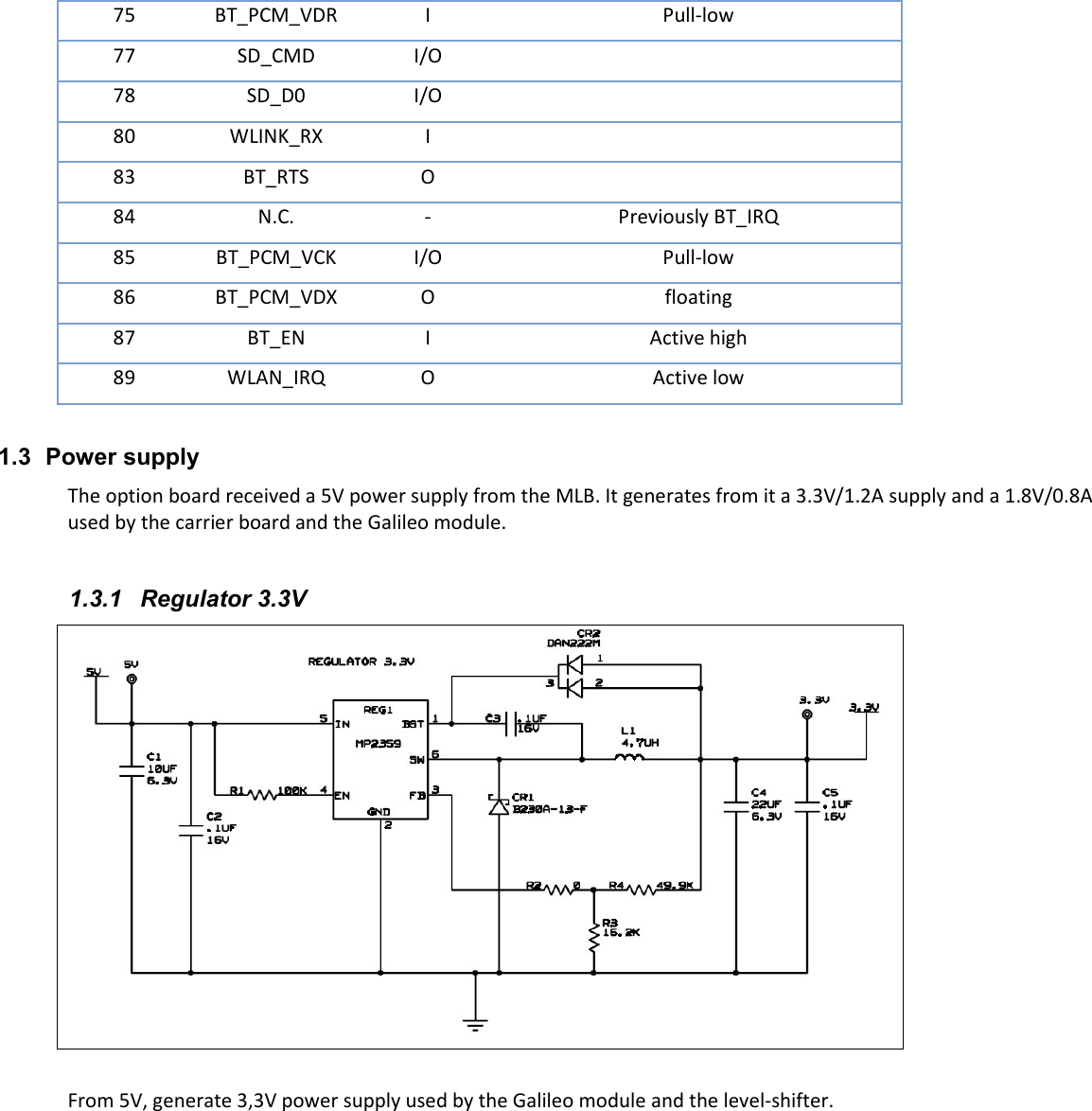
    Document Number: XXXXX  Communications  SystemsCommunications  SystemsCommunications  SystemsCommunications  Systems     Statement Statement Statement Statement of Work:of Work:of Work:of Work:    Specifications  for  a  SDIO Specifications  for  a  SDIO Specifications  for  a  SDIO Specifications  for  a  SDIO  802.11 802.11 802.11 802.11 b/gb/gb/gb/g/n/n/n/n     Wireless  LANWireless  LANWireless  LANWireless  LAN     and  Bluetooth and  Bluetooth and  Bluetooth and  Bluetooth 2.1  Network  I2.1  Network  I2.1  Network  I2.1  Network  Interface  Land  Grid nterface  Land  Grid nterface  Land  Grid nterface  Land  Grid Array ModuleArray ModuleArray ModuleArray Module    Revision:  A 10/7/2011  Intermec Engineering
1  PURPOSE  This document describes the hardware design specifications of the Wireless abgn + Bluetooth option board for the Phoenix program.  1.1  System Block Diagram   1.2  Interfaces 1.2.1  Connector to Main Board Through a 30pin connector, right angle, 2mm pitch Input/Output direction is referenced from the view of the option board: • Input: from the MLB to the option board • Output: from option board to MLB Pin # Description I/O Pin # Description I/O 1 5V  2 5V  3 GND  4 GND  5 GND  6 SD_CMD IO 7 GND  8 SD_D0 IO 9 GND  10 SD_D1 IO 11 GND  12 SD_D2 IO 13 GND  14 SD_D3 IO 15 GND  16 SD_CLK I 17 GND  18 GND  19 WIFI_PWR I 20 BT_PWR I 21 WLAN_IRQ O 22 BT_RX I 23 SCL I 24 BT_TX O
25 SDA IO 26 BT_RTS  27 BT_IRQ O 28 BT_CTS  29 GND  30 GND   1.2.2  RF Coaxial connector RP-TNC Connector, Right Angle, Jack Bulkhead from DynaHz. MPN: 26-800x-11040. Current MPN is 26-8003-11040. IPN: 351-486-001  1.2.3  Interface to Galileo module Refer to [1] “Galileo abgn System Specifications.doc”, referred as CDC doc# “636425” for the complete description of the interface to Galileo module.  Below is an extract of the important signals to communicate to the Galileo module. Input/Output direction is referenced from the view of the Galileo module: • Input: from the carrier board to Galileo • Output: from Galileo to carrier board Pin # Description I/O Remark 7 Vbat I  8 Vbat I  16 32kHz_CLK I  20 VDDIO I  32 VDDIO I  39 BATTERY_OK I  43 BT+PWR_EN I Active high 45 802.11_PWR_EN I  52 2.4_5GHz_RF I/O 50 Ohm RF I/O 61 BT_RX I  62 BT_TX O  63 BT_PCM_VFS I/O Pull-low 64 SD_D3 I/O  65 SD_D1 I/O  66 SD_CLK I  67 SD_D2 I/O  68 WLINK_TX O  74 BT_CTS I
75 BT_PCM_VDR I Pull-low 77 SD_CMD I/O  78 SD_D0 I/O  80 WLINK_RX I  83 BT_RTS O  84 N.C. - Previously BT_IRQ 85 BT_PCM_VCK I/O Pull-low 86 BT_PCM_VDX O floating 87 BT_EN I Active high 89 WLAN_IRQ O Active low  1.3  Power supply The option board received a 5V power supply from the MLB. It generates from it a 3.3V/1.2A supply and a 1.8V/0.8A used by the carrier board and the Galileo module.  1.3.1  Regulator 3.3V   From 5V, generate 3,3V power supply used by the Galileo module and the level-shifter.
1.3.2  Regulator 1.8V   From 3.3V, generate 1.8V power supply used by the Galileo module, the slow clock and the level-shifter.  1.4  Level shifter   The level shifter is used to change the 1.8V signals coming from the Galileo module to a 3.3V signals compliant with the MLB signal requirements, and vice-versa.
The signals converted from 3.3V to 1.8V and 1.8V to 3.3V are as followed: • WIFI_PWR • WLAN_IRQ • BT_PWR • BT_RX • BT_TX • BT_RTS • BT_CTS Notes:   (1) The  CPU on the MLB is configured  to  work  with  1.8V  signals. In this case the SDIO signals out of the Galileo module do not need to be modified. (2) Provision  is  made  to  convert  the  CLK_32kHz  and  all  SDIO  signals  via  the  level  shifter  through  uncounted resistors.  1.5  Clock 1.5.1  32kHz   Slow clock for the Galileo module  1.5.2  26MHz Internal fast clock of the Galileo module  This document is intended for Intermec Development Engineering and System Test Engineering. This document contains information regarding the design, development and testing of a SDIO based IEEE 802.11 bgn and High  Speed  UART  Bluetooth  network  interface  MODULE  based  on  a  newly  developed  Intermec  Wireless  platform  name Galileo.    This variant is named Galileo Galileo Galileo Galileo bgbgbgbgnnnn
2  RC12 Overview  RRRRC12 C12 C12 C12 is an embedded wireless device platform that uses a 90 PAD Land Grid Array (LGA) form factor to allow for a low cost  solution  to  mount  highly  integrated  chipsets  or  OEM/ODM  MODULESMODULESMODULESMODULES  onto  Intermec  products.    Galileo  uses solder-down re-flow mounting only to a host MLB – there are no screws, digital or RF connectors.    Test jigs are required to operate Galileo outside of a product.                                        Figure Figure Figure Figure 1111: RC12 platform: RC12 platform: RC12 platform: RC12 platform     The  RC12The  RC12The  RC12The  RC12  is  an  Intermec  designed  radio  platform  incorporating  the  MuRata  WLAN/Bluetooth  radio  module LBEH1Z9PFC-TEMP.     Please  see  reference  section  for  data  sheet.    This  device  is  a  dual  function  IEEE  802.11  bgn transceiver,  a  Bluetooth  2.1  compliant  radio  transceiver.    The  module  contains  independent  transceivers  for  each  radio technology; IEEE 802.11 and Bluetooth.    This variants system is capable of operating at the 2.4 GHz for the IEEE 802.11 transceiver, or 2.4 GHz band for the Bluetooth transceiver.     The MuRata MODULE is based on the following 802.11 and Bluetooth chipsets from Texas Instruments;  WL1273    Single-Chip MAC baseband processor and RF transceiver supporting 802.11 b/g/n standard  The RC12The RC12The RC12The RC12 and subsequent variants will be manufactured by Contract manufacturer.    Intermec is responsible for ensuring proper manufacturing test of the current and future designs. 2.1  IEEE802.11 transceiver description The IEEE 802.11 transceiver is based on the Texas Instruments WL1273 single-chip IEEE 802.11bgn MAC, Baseband, and Direct  Conversion  transceiver.    This  system  functions to  provide  wireless  LAN  connectivity  supporting  data  rates  from  1 Mbps to 54 Mbps and MCS0 to MCS7 in the 2.4-GHz band.    The Triquint TQP6M9002 provides RF frontend capabilities for the 2.4 GHz.    This variant only allows the 2.4 GHz transceiver to be in operation.      The Texas Instruments WL1273 employs a 4-Wire SDIO system bus interface to the HOST.  The PLATFORM uses a single antenna port for the 2.4 GHz of the IEEE transceivers.  The system provides a typical power output in the 2.4 GHz band of 17.5 dBm.  The 2.4 GHz transceiver supports data rates of 1, 2, 5.5 and 11 Mbps using CCK/DSSS and 6, 9, 12, 18, 24, 36, 48 and 54 Mbps using OFDM as per IEEE802.11-2007.    Data rates MCS0 to MCS7 conform to amendment IEEE802.11n-2009.
The system is designed to only use the 20 MHz occupied BW capacity. Data rates MCS0 to MCS7 conform to amendment IEEE802.11n-2009.  Data transmission from the IEEE transceiver is initiated by the IEEE 802.11 compliant MAC software.    The source of data to  transmit  can  either  be  user  supplied  data  (from  the  host  systems)  or  network  control  packets  (ACK’s  CTS,  PSPoll, ProbeRequest etc).    The transmitter is only active during the transmission of one of the packets previously mentioned.     2.2  Bluetooth transceiver description The  Bluetooth  subsystem  is  built  on  the  Texas  Instruments  BRF6450  ;  a  single-chip  CMOS,  Bluetooth®  2.1-compliant, Enhanced Data Rate (EDR) capable, stand-alone baseband processor with an integrated 2.4-GHz transceiver. The BRF6450 transceiver uses the Bluetooth SIG standard Host Controller Interface (HCI) via 4-Wire HighSpeed UART and PCM audio interfaces.    The  BRF6450  incorporates  all  Bluetooth  2.1  features  including  eSCO,  AFH,  and  support  for  collaborative coexistence with WLAN devices.    The Bluetooth transceiver uses a single independent antenna that is common with the IEEE Transceiver.  The Bluetooth transceiver is built with a Bluetooth Class 1.5 specification RF output power (approx +6 dBm, for an approx 50meter range).  The Bluetooth transceiver uses Bluetooth compliant frequency hopping spread spectrum to cover 79 channels 1 MHz wide from 2.402 GHz to 2.481 GHz.  The Bluetooth transceiver supports Bluetooth Basic data rates of 1 Mbps (GFSK) as well as Enhanced Data Rates of 2 Mbps (π/4-DQPSK) and 3 Mbps (8-DPSK)  Data transmission from the Bluetooth transceiver is controlled by software in the baseband processor. 2.3  Simultaneous operation Simultaneous operation of the WL1273 and BRF6450 transmitters is not possible when WiFi is operating on 802.11bgn (2.4 GHz).  While  in  operation,  coexistence  is  always  enabled.  This  arbitrates  packets  so  that  WiFi  and  Bluetooth  packets are alternately transmitted.    That is the transmissions are time division multiplexed.  The test tool does not allow simultaneous transmitter operation of 802.11bgn or 802.11an and Bluetooth.
3  System Level Requirements  The following is a summary list of MODULE baseline requirements that are detailed in subsequent clauses.    This reflects the current 802.11 bgn implementation and will change to reflect any future updates such as 802.11n. Table Table Table Table 3333----1111.    Summ.    Summ.    Summ.    Summary System Level Requirementsary System Level Requirementsary System Level Requirementsary System Level Requirements     Radio  Feature  Description WiFi 802.11bgn Physical Layer   Single Stream Transceiver with HT Preamble support Data rates 1, 2, 5.5,11,    6, 9, 12, 18, 24, 36, 48, 54, MCS0-7 2.4 GHz band Conducted b rates RF Power 17.0 dBm +/-1.0 dB for DSSS/CCK 2.4 GHz band Conducted g rates 6 – 36 Mbps RF Power 13 dBm +/-1.0 dB OFDM 48 – 54 Mbps RF Power 11.5 dBm +/- 1.0 dB OFDM MCS0 – MCS5 RF Power 13 dBm +/- 1.0 dB OFDM MCS6 – MCS7 RF Power 11.5 dBm +/- 1.0 OFDM Sensitivity -95dBm@1 Mbps / -70 dBm@54 Mbps OFDM Normal (800us) and Short Guard (400us) interval  RX STBC, RIFS, and 20/40 MHz Coexitence support RF/Antenna Interface  RF port for WiFi 2.4 GHz band Share RF port with Bluetooth Host Interface Driver SDIO 4 wire interface to Host Windows Mobile 6.X, Linux (Kernel 2.6)    Compliant SW architecture    Low Host Burden FullMAC SW architecture  A-MPDU (TX/RX), A-MSDU (RX), Block ACK support  Security  802.11 MAC contained on device Capable of WPA/WPA2/802.11i WEP/TKIP/AES encryption Cisco Compliance Coexistence Capable of CCXv4 minimum with path to CCXv5 802.15.2 Coexistence with co-located Bluetooth Supply Requirement  Low Power Operation 3.3 Vcc     Device IO I/F at 1.8Vdc  Bluetooth Bluetooth 2.1 Class 1.5   Conducted GFSK 100% Duty Cycle    RF Output Power = 6.5 dBm +/- 1 dB 2-EDR 100% Duty Cycle RF Output Power = 5.5 dBm +/- 1 dB 3-EDR 100 % Duty Cycle RF Output Power = 5.5 dBm +/- 1 dB 1 Mbps GFSK, 2 Mbps π/4-PSK, 3 Mbps 8-PSK Sensitivity better than -80 dBm all data rates World-Wide Regulatory Support    2.4 to 2.4835 GHz Band,   RF/Antenna Interface  Shares antenna with WiFi Host Interface  UART 4 wire interface to Host (RX,TX,CTS,RTS) HCI Data rates approx 4 Mbps Driver  Windows Mobile 6.0 BT Stack Compliant SW architecture    Autonomous Flash based design Coexistence  802.15.2 Coexistence with co-located WiFi Supply Requirement  Low Power Operation 3.3 VDC PCM Interface  Slave or Master mode 4 – Wire (IN,OUT,CLK,SYNC) Power Management  BT_WAKE and HOST_WAKE

Navigation menu