Intermec Technologies RM91501X04 RF Tag Reader User Manual 91501 Rdr QkSt

Intermec Technologies Corporation RF Tag Reader 91501 Rdr QkSt

Contents

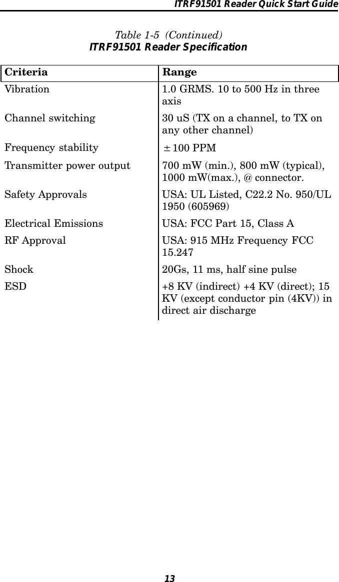
ITRM91501 Quick Start Guide

ITRF91501ReaderQuick Start GuidePRELIMINARYEDITION 20 June 02
ITRF91501 Reader Quick Start Guide2Packing ListWARNING: This is a Class A product. In a domesticenvironment this product may cause radiointerference in which case the user may berequired to take adequate measures.Check to ensure that you receive these items:IntermecRITRF91501 MHz ReaderModel Number ITRF91501(part number country dependent)Product Warranty CardCompliance StatementRF ID 915 MHz 33 x 105 Container Sample Tagsp/n ITTP9151002
ITRF91501 Reader Quick Start Guide3Host CommunicationHost communication comes through the 9-pin female D-subconnector. Both RS-232 and RS-422 standards are supported asordered from the factory or service centerTable 1-1RS-232 ConnectionsPin Number Definition2 Serial Data from the Fixed Reader to the host3 Serial Data to the Fixed Reader from the host5 Ground7 CTS (Clear to Send) to the Fixed Reader from thehost8 RTS (Request to Send) from the Fixed Reader to thehostTable 1-2RS-422 ConnectionsPin Number Definition1 Serial Data Out + from the Fixed Reader to the host4 Serial Data Out -- from the Fixed Reader to the host5 Ground6 Serial Data In + to the Fixed Reader from the host9 Serial Data In -- to the Fixed Reader from the hostThe default baud rate is 115.2 kbps with 8 data bits, no parity,and 1 stop bit.
ITRF91501 Reader Quick Start Guide4Power RequirementsPower comes in from 8 to 10 volts DC. The Fixed Reader usesless than 2 amps. Intermec supplies 9 volts DC at 2.4 ampsfrom Intermec power supply, p/n: 351-066-001.User I/OA general purpose I/O (Input/Output) connector provides signallines in and out of the reader allowing monitoring and/or con-trol of external devices or functions.The connector for this is a 13-pin female circular DIN. Themating male connector you need for mating with this is an In-termec p/nL 351-184-001.Table 1-3I/O Pin-outsPin Number Definition1GPIOIN02GPIOIN13GPIOIN24GPIOIN35GPIOOUT06GPIOOUT17GPIOOUT28GPIOOUT39, 10, 11, 12, 13 GROUND though individual 10 ohm resistorsOutputs and inputs have 12 volt transient suppression devicesto ground at the connector. Output signals are driven by2N3904 NPN transistors (low level) with a 100 kohm pull--upto +5 volts through a silicon diode, giving about a 4.3 volt highlevel. An output can be pulled high from an external source ashigh as 40 volts. This will however tend to pull the other out-puts higher (through two 100k resistors). The low level will beabout 0.1 volt up to about 30 mA. The output low voltage will
ITRF91501 Reader Quick Start Guide5climb higher as the sink current increases. There is no protec-tion on this. You need to ensure that their load won’t requirethereadertosinkmorethan50mA.Input signals should be 0 to +1.5 volt for a low input and +3.5to +5 volts for a high input. Each input has a 1.1 kohm resistorin series with clamping diodes, but only about 1µA is used untilthe input exceeds the 0 to +5 volt input range. There is also aweak (100 kohm) pull--up to +5 volt on each input.Connecting and Getting StartedWARNING: FCC regulations limit exposure toradiofrequency (RF) radiation. To comply withthese regulations, operators of this device mustmaintain a distance of at least 23 cm. (9.1inches) from the cover on the antenna assembly(The cover on the antenna is the dome shapedsurface). While the device is on, the operator’sbody and parts of the body such as eyes, hands,or head, must be 23 cm. (9.1 inches) or fartherfrom the cover of the antenna assembly.FCC regulations also require that the antennaassembly of this device be installed inaccordance with the installation procedures toallow the operator to comply with the limit.Antenna InstallationEnsure that you read the above warning before installing theantennas and using your Reader product.
ITRF91501 Reader Quick Start Guide6Front view of the antenna1. Review the locations where the Reader products need in-tegrated. Ensure that you have careful considered thesafe distances for product placement for workers and anyother personnel that may get in the RF path.2 . Place t he radio and antennas w ith c abling are easily ac -cessible for installation and troubleshooting.3. Use the mounting bracket to attach the antenna to afixed surface.4. Attach the antenna to one of the four antenna ports onthe back of the Reader.5. Do not transmit simultaneously with multiple antennas.
ITRF91501 Reader Quick Start Guide7The following illustrations are a couple of examples for Readerinstallations.EXAMPLE 1: Shipping Dock Door, showing two antennas at eachshipping door. Two antennas in a crossing patternprovide angular diversity to improve read capabilitywhen tag orientation is unknown.WARNING: While the device is on, the operator’s body andparts of the body such as eyes, hands, or head,must be 23 cm. (9.1 inches) or farther from thecover of the antenna assembly.Shipping Door #1 Shipping Door #2100” Max.distanceto tagA singular antenna in a portal may be sufficientin applications where there is a known tag orientation.
ITRF91501 Reader Quick Start Guide8EXAMPLE 2: Two Product Line Conveyers, showing two antennason each line. Two antennas in a crossing patternprovide angular diversity to improve read capabilitywhen tag orientation is unknown.The frames for these stations are PVC tubing with RF reflec-tive Mylar liner X2. Ensure that an 9.1 inch (23 cm) distancefrom the antenna assembly is maintained to limit people’s ex-posure to radiofrequency (RF) radiation.WARNING: While the device is on, the operator’s body andparts of the body such as eyes, hands, or head,must be 23 cm. (9.1 inches) or farther from thecover of the antenna assembly.Conveyer Belt #1Conveyer Belt #2A singular antenna in a portal may be sufficientin applications where there is a known tag orientation.100” Max.distanceto tag
ITRF91501 Reader Quick Start Guide9Connecting the Antenna to the Reader1. Connect antenna cable to a port.2. Connect a reverse-sex SMA terminator (Intermec p/n345-004-001) to any port that does not have an antennaattached."NOTE: Each port must have either an antenna or a termina-tor connected.1234Antenna portsBack panel Antenna cableSMA terminator3. Connect the Reader to a power source using power supplyp/n 351-066-001 and country dependent AC power cord.4. Turn on your Reader.Power supplyPower cord
ITRF91501 Reader Quick Start Guide105. Review the front panel LEDs to become familiar with thestatus indications you will receive from your Reader.RS-232 orRS-422 portI (ON) O (OFF) switchAuxilary I/O connectorPower supply jackLEDs position(lefttoright)0,1,2,30123LED MeaningLED 0 Reader has power is initialized and ready.LED 1 Reader is communicating with the host, it flashesas data transfer occurs.LED 2 Reader RF is ON and searching for TAGs.LED 3 Reader is communicating with a TAG, it flashes astransfer occurs.
ITRF91501 Reader Quick Start Guide11TroubleshootingTable 1-4TroubleshootingProblem SolutionDoesn’t recognize tag 1. Check to ensure antenna is con-nected to jack on Reader.2. Ensure Reader is connected toyour computer.3. Ensure computer is plugged intoac outlet and computer is turned on.4. Ensure tag is within range of an-tenna.5. Access the Intermec web sitehttp://www.intermec.com orhttp://NorBBS.Norand.com to down-load and run the diagnostic test util-ity PENNRFID.EXE.6. Call Intermec Technical Support800--755--5505 (US or Canada)425--356--1799 (elsewhere).Diagnostic PENNRFID.EXE UtilityShould your Reader fail to read tags, download the test utilityfrom the Intermec web site (http://www.intermec.com). Thisutility PENNRFID.EXE is a self-extracting zip file thatincludes installation instructions and a test utility to check theoperation of the Reader on a laptop or desktop computer. Referto the README.TXT file included in the zip file forinstructions on using the test utility.Should the reader fail after running this utility, contact Inter-mec Technical Support and give them the error codes you ob-serve. They will step you through further diagnostic trouble-shooting.
ITRF91501 Reader Quick Start Guide12Performance SpecificationsDependent upon operating conditions and demands expected. Ifused in a normal office environment with good read conditions,you could expect to read up to six tags per second. Tags locatedtoo far away or in poor locations with respect to interferingobjects provides poor results. The Reader gets very warmduring continued use. In high ambient temperature (or hightemperature within host computer) conditions, the reader couldoverheat.Table 1-5ITRF91501 Reader SpecificationCriteria RangeOperating Temperature --20dto +55dC(--4dto +131dF)Storage Temperature --40dto +85dC(--40dto +185dF)Humidity 10--95% relative humidity, non-con-densing processFrequency 902--928 MHzTag data rates 32K bits per secondOperating Voltage 8--10 volts DCRipple 200 mV maximum Peak to PeakModulation AM, On/Off keyCoding Manchester: From reader to tagRF Output Impedance 50Ωw/better than 10 dB returnlossBus Interface Serial, RS-232 or RS-422Read Range 100 inches maximumWrite Range Typically 70% of Read RangeTag identification Up to 30 tags per secondWrite Rate 20 ms per byte per tagRead current 1.3 AmpsProtocol ANSI NCTIS T6 256-2001 stan-dard.
ITRF91501 Reader Quick Start Guide13Table 1-5 (Continued)ITRF91501 Reader SpecificationCriteria RangeVibration 1.0 GRMS. 10 to 500 Hz in threeaxisChannel switching 30 uS (TX on a channel, to TX onany other channel)Frequency stability ±100 PPMTransmitter power output 700 mW (min.), 800 mW (typical),1000 mW(max.), @ connector.Safety Approvals USA: UL Listed, C22.2 No. 950/UL1950 (605969)Electrical Emissions USA: FCC Part 15, Class ARF Approval USA: 915 MHz Frequency FCC15.247Shock 20Gs, 11 ms, half sine pulseESD +8 KV (indirect) +4 KV (direct); 15KV (except conductor pin (4KV)) indirect air discharge
ITRF91501 Reader Quick Start Guide14IITRF91501 Reader, Quick Start Guide-March, 2002*962054052*962054052 REV Awww.intermec.com

Navigation menu