Intermec 700 Color Users Manual Legal
700 Color - User's Manual 700_Series_Color Free User Guide for Intermec Mobile Phone, Manual
2015-07-27
: Intermec Intermec-700-Color-Users-Manual-775605 intermec-700-color-users-manual-775605 intermec pdf
Open the PDF directly: View PDF ![]() .
.
Page Count: 298 [warning: Documents this large are best viewed by clicking the View PDF Link!]
- Legal Information
- Document Change Record
- Contents
- Before You Begin
- Chapter 1 - Introduction
- Chapter 2 - Windows Mobile 2003
- Software Builds
- Where to Find Information
- Basic Skills
- Microsoft ActiveSync
- Microsoft Pocket Outlook
- Calendar: Scheduling Appointments and Meetings
- Synchronizing Calendar
- Why Use Categories in the Calendar?
- What’s an All Day Event?
- What’s a Recurrence Pattern?
- Viewing Appointments
- Creating or Changing an Appointment
- Creating an All Day Event
- Setting a Reminder for an Appointment
- Adding a Note to an Appointment
- Making an Appointment Recurring
- Assigning an Appointment to a Category
- Sending a Meeting Request
- Finding an Appointment
- Deleting an Appointment
- Changing Calendar Options
- Contacts: Tracking Friends and Colleagues
- Tasks: Keeping a To Do List
- Notes: Capturing Thoughts and Ideas
- Inbox: Sending and Receiving E-mail Messages
- Calendar: Scheduling Appointments and Meetings
- Companion Programs
- Pocket Internet Explorer
- Chapter 3 - Installing Applications
- Chapter 4 - Network Support
- Understanding Your 700 Color Computer
- Antennas (760/761 Computers)
- Personal Area Networks
- Local Area Networks
- Wide Area Networks
- Phone Applications
- Microsoft Phone Application (761 Computers with CDMA Radios)
- Microsoft Phone Application (761 Computers with GSM Radios)
- SB555 Watcher (760 Computers with CDMA Radios)
- Copying CDMA Radio Module CAB Files fromIntermec Web Site
- ViaMicrosoft ActiveSync
- Via a CompactFlash or Secure Digital Storage Card
- Finishing the Installation
- Activation
- Verizon Automated Activation Process
- Sprint Automated Activation Process
- Telus and Bell Mobility Activation
- AT Command Interface (760 Computers)
- Remote Access (Modems)
- Management
- Chapter 5 - Printer Support
- Chapter 6 - Scanner Support
- Chapter 7 - Programming
- Appendix A - Configurable Settings
- Appendix B - Troubleshooting
- Index
700 Series Color
Mobile Computer
User's Manual
ii 700 Series Color Mobile Computer User’s Manual
Intermec Technologies Corporation
Worldwide Headquarters Cedar Rapids Technical Communications
6001 36th Ave. W. 550 Second Street SE
Everett, WA 98203 Cedar Rapids, IA 52401
U.S.A. U.S.A.
www.intermec.com
The information contained herein is provided solely for the purpose of allowing customers to operate and
service Intermec-manufactured equipment and is not to be released, reproduced, or used for any other
purpose without written permission of Intermec Technologies Corporation.
Information and specifications contained in this document are subject to change without prior notice and do
not represent a commitment on the part of Intermec Technologies Corporation.
E2002-2006 by Intermec Technologies Corporation. All rights reserved.
The word Intermec, the Intermec logo, Norand, ArciTech, Beverage Routebook, CrossBar, dcBrowser,
Duratherm, EasyADC, EasyCoder, EasySet, Fingerprint, i-gistics, INCA (under license), Intellitag, Intellitag
Gen2, JANUS, LabelShop, MobileLAN, Picolink, Ready-to-Work, RoutePower, Sabre, ScanPlus, ShopScan,
Smart Mobile Computing, TE 2000, Trakker Antares, and Vista Powered are either trademarks or registered
trademarks of Intermec Technologies Corporation.
There are U.S. and foreign patents as well as U.S. and foreign patent applications pending.
Wi-Fi is a registered certification mark of the Wi-Fi Alliance.
Microsoft, Windows, and the Windows logo are registered trademarks of Microsoft Corporation in the
United States and/or other countries.
Bluetooth is a trademark of Bluetooth SIG, Inc., U.S.A.
This product includes software developed by the OpenSSL Project for use in the Open SSL Toolkit.
(www.openssl.org)
This product includes cryptographic software written by Eric Young (EAY@cryptsoft.com).
This product uses Regex++, Index software during its operational phases. The owner of Regex++ has granted
use of the software to anyone provided such use is accompanied by the following copyright and permission
notice:
Regex++, Index. (Version 3.31, 16th Dec 2001)
Copyright E1998-2001 Dr John Maddock
Permission to use, copy, modify, distribute and sell this software and its documentation for any purpose is
hereby granted without fee, provided that the above copyright notice appear in all copies and that both that
copyright notice and this permission notice appear in supporting documentation. Dr John Maddock makes
no representation about the suitability of this software for any purpose. It is provided “as is” without express
or implied warranty.

iii700 Series Color Mobile Computer User’s Manual
Document Change Record
This page records changes to this document. The document was originally
released as Revision A.
Revision
Letter Date Description of Change
B11/2002 Added information about the Siemens MC45 radio mod-
ule, the tethered scanner, CAB extraction, FTP Server pa-
rameters, and Data Collection control panel applet imager
options.
C04/2003 Added information about the ambient light sensor, the
beeper, keypad sequences, the alphanumeric keypad, the
vibrator, an accessories list, programming notifications, the
MaxiCode symbology, the Utilities control panel applet,
and the Wireless Network control panel applet.
D08/2003 Upgraded Pocket PC 2002 information to Windows Mo-
bile 2003, upgraded all illustrations to gray-scale, added
new Imager functions, moved the Automatic Data Collec-
tion COM Interface material to the SDK User’s Manual.
E01/2004 Added 730 Computer information, revised CDMA Setup
information, and revised Wireless Area Network Printing
information.
F04/2004 Updated 802.11 security supplicant information. Added
new network selection APIs. Incorporated information
about the Intermec Settings control panel applet for PSM
Builds 3.00 or newer. Added information about the Pho-
neUtility application. Revised Chapter 4, “Network Sup-
port.” Added tethered scanner and internal scanner config-
uration and troubleshooting information to Chapter 6,
“Scanner Support.”
G01/2005 Added information about resetting the 700 Series Comput-
er. Updated the Profile Wizard information in Appendix
A, “Configurable Settings.” Revised information about
using Sprint Watcher and added information about a
Phone application for units with CDMA or GSM radios in
Chapter 4, “Network Support.” Added information about
the 741, 751, and 761 Computers and the MC46 Radio.
H07/2005 Added information on performing a warm-boot, LED sta-
tus, replicating settings using the registry, troubleshooting,
and specifications.
J06/2006 Updated to include RoHS model numbers, removed infor-
mation for operating systems builds older than 3.0, added
information about EL10 Laser Scanners, scan engine read-
ing distances, PB42 Portable Printers, pull tabs on storage
cards, RFID support, and the MC75 Radio.
iv 700 Series Color Mobile Computer User’s Manual
Contents
v700 Series Color Mobile Computer User’s Manual
Contents
Before You Begin xv.............................................................
Safety Information xv.....................................................
Global Services and Support xv..............................................
Warranty Information xv............................................
Web Support xv...................................................
Telephone Support xvi...............................................
WhoShouldReadThisManual xvi...........................................
Related Documents xvi.....................................................
Patent Information xvii....................................................
Introduction 1...............................................................
AB10 Battery 2.................................................................
Ambient Light Sensor 4..........................................................
Audio System 4.................................................................
Speaker 5...............................................................
Microphone 5...........................................................
External Headset Jack 6....................................................
Beeper 7......................................................................
Enable the Beeper 7.......................................................
Disable the Scanner Mute 7.................................................
Select a Beeper Volume 8...................................................
Disable the Beeper 9......................................................
Intermec Settings Applet 9........................................................
Keypads 10....................................................................
700 Color Keypads 10.....................................................
Backlight for Keypad 10....................................................
Key Sequences 11.........................................................
[Gold] or [Gold/White] Plane Keys 11..................................
Alpha (Blue) Plane Keys 12...........................................
LEDs 14......................................................................
Modem Support 15..............................................................
PSM Build Version 15...........................................................
1
Contents
vi 700 Series Color Mobile Computer User’s Manual
Resetting Your 700 Color Computer 16..............................................
Performing a Warm-Boot 16................................................
Performing a Cold-Boot 16.................................................
Software Build Version 17.........................................................
Software Tools 17...............................................................
SmartSystemst Foundation Console (www.intermec.com/SmartSystems) 17............
Intermec Resource Kits (www.intermec.com/IDL) 17.............................
Storage Media 18...............................................................
Storage Cards Available 18..................................................
CompactFlash Cards 18.............................................
Secure Digital Cards 18..............................................
SIM Cards 18.....................................................
700 Color Computers 18...................................................
730 Computers 18........................................................
Internal Card Slots 19.....................................................
Inserting the Storage Card 19................................................
Vibrator 20....................................................................
Wireless Network Support 21......................................................
Accessories 21..................................................................
Physical and Environmental Specifications 21..........................................
Windows Mobile 2003 25....................................................
Software Builds 26..............................................................
Where to Find Information 26.....................................................
Basic Skills 26..................................................................
Today Screen 26..........................................................
Programs 27.............................................................
Navigation Bar and Command Bar 28.........................................
Pop-up Menus 28........................................................
Notifications 29..........................................................
Entering Information 29...................................................
Typing With the Onscreen Keyboard 30................................
Using Block Recognizer 31...........................................
Using Letter Recognizer 32...........................................
Using Transcriber 32................................................
Selecting Typed Text 32.............................................
2
Contents
vii700 Series Color Mobile Computer User’s Manual
Writing on the Screen 32...................................................
Selecting the Writing 33.............................................
Converting Writing to Text 33........................................
Drawing on the Screen 35..................................................
Creating a Drawing 35..............................................
Selecting a Drawing 35..............................................
Recording a Message 36....................................................
Using My Text 36........................................................
Finding and Organizing Information 37.......................................
Customizing Your 700 Color Computer 38.....................................
Adjusting Settings 38...............................................
Adding or Removing Programs 38.....................................
Microsoft ActiveSync 41..........................................................
Microsoft Pocket Outlook 42......................................................
Calendar: Scheduling Appointments and Meetings 42.............................
Synchronizing Calendar 43...........................................
Why Use Categories in the Calendar? 43................................
What’s an All Day Event? 44.........................................
What’s a Recurrence Pattern? 45.......................................
Viewing Appointments 46............................................
Creating or Changing an Appointment 47...............................
Creating an All Day Event 48.........................................
Setting a Reminder for an Appointment 48...............................
Adding a Note to an Appointment 49...................................
Making an Appointment Recurring 50..................................
Assigning an Appointment to a Category 50..............................
Sending a Meeting Request 51........................................
Finding an Appointment 52..........................................
Deleting an Appointment 53..........................................
Changing Calendar Options 53.......................................
Contacts: Tracking Friends and Colleagues 53...................................
Creating a Contact 54...............................................
Synchronizing Contacts 55...........................................
Viewing Contacts 55................................................
Creating or Changing a Contact 56....................................
Adding a Note to a Contact 56........................................
Assigning a Contact to a Category 57...................................
Copying a Contact 57...............................................
Sending a Message to a Contact 58.....................................
Finding a Contact 58...............................................
Deleting a Contact 59...............................................
Adding a Contact to Speed Dial 59.....................................
Changing Contacts Options 59........................................
Tasks: Keeping a To Do List 60..............................................
Creating a Task 61.................................................
Synchronizing Tasks 61..............................................
Notes: Capturing Thoughts and Ideas 62......................................
Creating a Note 62.................................................
Synchronizing Notes 63.............................................
Contents
viii 700 Series Color Mobile Computer User’s Manual
Inbox: Sending and Receiving E-mail Messages 63...............................
Synchronizing E-mail Messages 64.....................................
Managing E-mail Messages and Folders 64...............................
Connecting to a Mail Server 65........................................
Composing and Sending Messages 66...................................
Companion Programs 67.........................................................
Pocket Word 68..........................................................
Creating a Document 68.............................................
Typing Mode 69...................................................
Writing Mode 70..................................................
Recording Mode 70................................................
Drawing Mode 70..................................................
Synchronizing Pocket Word Documents 71..............................
Pocket Excel 71..........................................................
Creating a Workbook 72.............................................
Tips for Working in Pocket Excel 72...................................
MSN Messenger 73.......................................................
Setting Up an Account 74............................................
Signing In and Out 74..............................................
Working with Contacts 75...........................................
Managing Contacts 75..............................................
Sending a Message 76...............................................
Windows Media Player for Windows Mobile 76.................................
Microsoft Reader 77.......................................................
Getting Books on Your 700 Color Computer 77..........................
Using the Library 78................................................
Reading a Book 78.................................................
Using Reader Features 79............................................
Removing a Book 79................................................
Pocket Internet Explorer 79........................................................
Mobile Favorites Folder 80.................................................
Favorite Links 80.........................................................
Mobile Favorites 80.......................................................
Using AvantGo Channels 81................................................
Using Pocket Internet Explorer 82............................................
Viewing Mobile Favorites and Channels 82..............................
Browsing the Internet 83.............................................
Installing Applications 85...................................................
Packaging an Application 86.......................................................
Installing Applications 87.........................................................
Using Microsoft ActiveSync 87..............................................
Using the FTP Server 88...................................................
Using a Storage Card 88...................................................
3
Contents
ix700 Series Color Mobile Computer User’s Manual
Replicating 700 Color Settings Using the Registry 88.............................
Deleting the Old Registry File 89......................................
Downloading the RegFlush CAB File 89................................
Loading the Registry Save Application 90................................
Confirming the New Registry File 90...................................
Updating Other Computers in Your Network 91..........................
Updating the System Software 92...................................................
Using a Storage Card to Upgrade the 700 Color Computer 93......................
Using the SmartSystems Console to Upgrade the 700 Color Computer 94.............
Migrating from a 700 Monochrome Computer 95......................................
Installing Cabinet Files 95.........................................................
Network Support 97.........................................................
Understanding Your 700 Color Computer 98..........................................
Antennas (760/761 Computers) 98..................................................
Personal Area Networks 99........................................................
About the Application 100..................................................
Mode 100........................................................
Wireless Printing 100...............................................
File Transfer 102...................................................
Connecting with Bluetooth 103..............................................
Local Area Networks 107.........................................................
Configuring USB Communications 107.......................................
Configuring 802.11 Radio Communications 108................................
Configuring the Network Parameters for a TCP/IP Network 108..............
Configuring the Network Parameters for a UDP Plus Network 108............
Network Adapters 108.....................................................
Ethernet Communications (740, 741, 750, 751, 760, 761 Computers) 109......
Wireless 802.11 Communications 110..................................
No Networking 110................................................
Network Selection APIs 110.................................................
Network Connections 111..................................................
Creating a Wireless Network Connection 111...................................
AutoIP/DHCP 116.......................................................
Wide Area Networks 116.........................................................
4
Contents
x 700 Series Color Mobile Computer User’s Manual
Phone Applications 116..........................................................
Microsoft Phone Application (761 Computers with CDMA Radios) 117..............
Data Provisioning (Sprint) 117........................................
Data Provisioning (Verizon) 119.......................................
Phone Application 120..............................................
Microsoft Phone Application (761 Computers with GSM Radios) 125................
Activation 126.....................................................
Phone Application 126..............................................
Phone Information 130..............................................
SB555 Watcher (760 Computers with CDMA Radios) 130........................
Copying CDMA Radio Module CAB Files from Intermec Web Site 131........
Via Microsoft ActiveSync 131.........................................
Via a CompactFlash or Secure Digital Storage Card 131.....................
Finishing the Installation 132.........................................
Activation 133.....................................................
Verizon Automated Activation Process 135...............................
Sprint Automated Activation Process 137................................
Telus and Bell Mobility Activation 143..................................
AT Command Interface (760 Computers) 143............................
Remote Access (Modems) 148.....................................................
Connecting to an Internet Service Provider (ISP) 148.............................
Connecting to Work 151...................................................
Creating a VPN Server Connection to Work 154................................
Ending a Connection 156..................................................
Management 156...............................................................
SmartSystemst Foundation Console (www.intermec.com/SmartSystems) 156...........
SNMP Configuration on the Mobile Computer 157..............................
Management Information Base 157....................................
Object Identifiers 158...............................................
Configuring with SNMP 159.........................................
Printer Support 161..........................................................
Printing ASCII 162..............................................................
Directly to a Port 162.....................................................
Directly to a Generic Serial Port 162..........................................
IrDA Printer Driver 162..........................................................
NPCP Printer Driver 163.........................................................
About NPCP 163........................................................
NPCP Driver Installation and Removal 163....................................
Opening the NPCP Driver 164..............................................
Closing the NPCP Driver 164...............................................
Reading from the NPCP Driver 164..........................................
Writing to the NPCP Driver 164.............................................
NPCP Driver I/O Controls 164..............................................
5
Contents
xi700 Series Color Mobile Computer User’s Manual
NPCP Printer Communications 165..........................................
Sample Code 166.........................................................
NPCP Error Codes 166....................................................
O’Neil Printer Driver 167.........................................................
DTR Driver Installation and Removal 167.....................................
Opening the DTR Driver 167...............................................
Closing the DTR Driver 168................................................
Writing to the DTR Driver 168..............................................
DTR Printer Communications 168...........................................
Configuring PB42 Printers Via Intermec Settings 168.............................
Scanner Support 169.........................................................
Scanner Control and Data Transfer 170..............................................
Data Collection Configuration 170..................................................
Internal Scanners 171............................................................
Scanner and Imager Settings 172.............................................
Internal Scanner Supported Symbologies 172....................................
Reading Distances 173.....................................................
Tethered Scanners 177...........................................................
Configuring the Tethered Scanner 177........................................
1551E or 1553 Selected for Scanner Model 178...........................
ASCII Selected for Scanner Model 179..................................
Troubleshooting the 1551E/1553 Tethered Scanner 179...........................
Reset Factory Defaults 180..................................................
Tethered Scanner Supported Symbologies 180...................................
Attached RFID Readers 181.......................................................
Reading RFID Tags with the Virtual Wedge 181................................
Disable Power to Bluetooth 183..............................................
Configure the Reader Using Intermec Settings 184...............................
Programming 187............................................................
Creating CAB Files 188..........................................................
Creating Device-Specific CAB Files 188.......................................
Creating an .INF File 188............................................
Sample .INF File 195...............................................
Using Installation Functions in SETUP.DLL 197................................
After the CAB File Extraction 198............................................
Creating CAB Files with CAB Wizard 201.....................................
Troubleshooting the CAB Wizard 201.........................................
6
7
Contents
xii 700 Series Color Mobile Computer User’s Manual
Customization and Lockdown 202..................................................
FTP Server 203.................................................................
Configurable Parameters Via the Registry Editor 204.............................
BlockSize 204.....................................................
DeviceName 204..................................................
DeviceURL 204...................................................
IDNATarget 204..................................................
ManifestName 205.................................................
PauseAtStartup 205.................................................
Root 205.........................................................
Transferring Files Over TCP/IP Networks 205..................................
Stopping the FTP Server from Your Application 208..............................
Autostart FTP 209........................................................
Kernel I/O Controls 210..........................................................
IOCTL_HAL_GET_DEVICE_INFO 210.....................................
IOCTL_HAL_ITC_READ_PARM 211.......................................
IOCTL_HAL_ITC_WRITE_SYSPARM 214...................................
IOCTL_HAL_GET_DEVICEID 215........................................
IOCTL_HAL_GET_OAL_VERINFO 216....................................
IOCTL_HAL_GET_BOOTLOADER_VERINFO 216..........................
IOCTL_HAL_WARMBOOT 217...........................................
IOCTL_HAL_COLDBOOT 217............................................
IOCTL_HAL_GET_RESET_INFO 218......................................
IOCTL_HAL_GET_BOOT_DEVICE 219....................................
IOCTL_HAL_REBOOT 219...............................................
IOCTL_PROCESSOR_INFORMATION 220.................................
IOCTL_GET_CPU_ID 220................................................
Network Selection APIs 221.......................................................
Notifications 221...............................................................
NLEDGetDeviceInfo 221..................................................
NLEDSetDevice 222......................................................
Reboot Functions 222............................................................
Remapping the Keypad 223.......................................................
Unshifted Plane 223.......................................................
Gold Plane 223..........................................................
Alpha (Blue) Plane 224....................................................
Key Values 224..........................................................
Numeric Keypad 224...............................................
Alphanumeric Keypad 224...........................................
How Key Values Are Stored in Registry 224....................................
Change Notification 225...................................................
Advanced Keypad Remapping 225............................................
Contents
xiii700 Series Color Mobile Computer User’s Manual
Scan Codes 226..........................................................
Sample View of Registry Keys 228............................................
Configurable Settings 229...................................................
Configuration Parameters 230......................................................
Intermec Settings Applet 231......................................................
Utilities Applet 231..............................................................
Dock Switch 232.........................................................
Registry Save 232.........................................................
Wakeup Mask 233........................................................
App Launch 234.........................................................
Wireless Network Applet 235......................................................
About the Wireless Network 235.............................................
Terminology 235.........................................................
Configuring Your Wireless Network 236.......................................
Basic 237.........................................................
Security 238......................................................
Advanced 252.....................................................
Other Configurable Parameters 253.................................................
Using Reader Commands 254......................................................
Change Configuration 254.................................................
Set Time and Date 255....................................................
Configuration Bar Codes 255......................................................
Audio Volume 255........................................................
Automatic Shutoff 256.....................................................
Backlight Timeout 256....................................................
Key Clicks 257...........................................................
Virtual Wedge Grid, Preamble, Postamble 257..................................
Grid 257.........................................................
Preamble 258.....................................................
Postamble 258.....................................................
Troubleshooting 259.........................................................
A
B
Contents
xiv 700 Series Color Mobile Computer User’s Manual
Index
Classes and Functions 262........................................................
General Index 267...............................................................
Files Index 278.................................................................
I

Before You Begin
xv700 Series Color Mobile Computer User’s Manual
Before You Begin
This section provides you with safety information, technical support
information, and sources for additional product information.
Safety Information
Your safety is extremely important. Read and follow all warnings and
cautions in this document before handling and operating Intermec
equipment. You can be seriously injured, and equipment and data can be
damaged if you do not follow the safety warnings and cautions.
This section explains how to identify and understand warnings and notes
that are in this document.
A warning alerts you of an operating procedure, practice, condition,
or statement that must be strictly observed to avoid death or serious
injury to the persons working on the equipment.
Note: Notes either provide extra information about a topic or contain
special instructions for handling a particular condition or set of
circumstances.
Global Services and Support
Warranty Information
To understand the warranty for your Intermec product, visit the Intermec
web site at www.intermec.com and click Service & Support.TheIntermec
Global Sales & Service page appears. From the Service & Support menu,
move your pointer over Support, and then click Warranty.
Disclaimer of warranties: The sample code included in this document is
presented for reference only. The code does not necessarily represent
complete, tested programs. The code is provided “as is with all faults.” All
warranties are expressly disclaimed, including the implied warranties of
merchantability and fitness for a particular purpose.
Web Support
Visit the Intermec web site at www.intermec.com to download our current
documents (in PDF). To order printed versions of the Intermec manuals,
contact your local Intermec representative or distributor.
Visit the Intermec technical knowledge base (Knowledge Central) at
intermec.custhelp.com to review technical information or to request
technical support for your Intermec product.

Before You Begin
xvi 700 Series Color Mobile Computer User’s Manual
Telephone Support
These services are available from Intermec Technologies Corporation.
Service Description
In the U.S.A. and Canada
call 1-800-755-5505
and choose this option
Order Intermec
products
SPlace an order.
SAsk about an existing order.
1 and then choose 2
Order Intermec
media
Order printer labels and ribbons. 1 and then choose 1
Order spare parts Order spare parts. 1 or 2 and then choose 4
Technical Support Talk to technical support about
your Intermec product.
2 and then choose 2
Service SGet a return authorization
number for authorized service
center repair.
SRequest an on-site repair
technician.
2 and then choose 1
Service contracts SAsk about an existing contract.
SRenew a contract.
SInquire about repair billing or
other service invoicing questions.
1 or 2 and then choose 3
Outside the U.S.A. and Canada, contact your local Intermec
representative. To search for your local representative, from the Intermec
web site, click Contact.
Who Should Read This Manual
This document is written for the person who is responsible for installing,
configuring, and maintaining the 700 Series Color Mobile Computer.
This document provides you with information about the features of the
700 Color and how to install, configure, operate, maintain, and
troubleshoot it.
Before you work with the 700 Color, you should be familiar with your
network and general networking terms, such as IP address.
Related Documents
This table contains a list of related Intermec documents and their part
numbers.
Document Title Part Number
700 Color with Windows Mobile 2003 Quick Start Guide 962-054-069
730 Mobile Computer Quick Start Guide 962-054-068
Intermec Computer Command Reference Manual 073529
700C Recovery CD Windows Mobile 2003 Edition English 235-110-001 (Kit)
Before You Begin
xvii700 Series Color Mobile Computer User’s Manual
The Intermec web site at www.intermec.com contains our documents (as
PDF files) that you can download for free.
To download documents
1Visit the Intermec web site at www.intermec.com.
2Click Service & Support >Manuals.
3In the Select a Product field, choose the product whose documentation
you want to download.
To order printed versions of the Intermec manuals, contact your local
Intermec representative or distributor.
Patent Information
Product is covered by one or more of the following patents: 4,882,476;
4,894,523; 4,953,113; 4,961,043; 4,970,379; 4,988,852; 5,019,699;
5,021,642; 5,038,024; 5,081,343; 5,095,197; 5,144,119; 5,144,121;
5,182,441; 5,187,355; 5,187,356; 5,195,183; 5,195,183; 5,195,183;
5,216,233; 5,216,550; 5,218,191; 5,227,614; 5,233,172; 5,241,488;
5,243,602; 5,258,606; 5,278,487; 5,288,985; 5,308,966; 5,322,991;
5,331,136; 5,331,580; 5,342,210; 5,349,678; 5,359,185; 5,371,858;
5,373,478; 5,389,770; 5,397,885; 5,410,141; 5,414,251; 5,416,463;
5,442,167; 5,464,972; 5,468,947; 5,468,950; 5,477,044; 5,486,689;
5,488,575; 5,500,516; 5,502,297; 5,504,367; 5,508,599; 5,514,858;
5,530,619; 5,534,684; 5,536,924; 5,539,191; 5,541,419; 5,548,108;
5,550,362; 5,550,364; 5,565,669; 5,567,925; 5,568,645; 5,572,007;
5,576,529; 5,592,512; 5,594,230; 5,598,007; 5,608,578; 5,616,909;
5,619,027; 5,627,360; 5,640,001; 5,657,317; 5,659,431; 5,671,436;
5,672,860; 5,684,290; 5,719,678; 5,729,003; 5,793,604; 5,742,041;
5,761,219; 5,764,798; 5,777,308; 5,777,309; 5,777,310; 5,786,583;
5,798,509; 5,798,513; 5,804,805; 5,805,807; 5,811,776; 5,811,777;
5,818,027; 5,821,523; 5,828,052; 5,831,819; 5,834,749; 5,834,753;
5,837,987; 5,841,121; 5,842,070; 5,844,222; 5,854,478; 5,862,267;
5,869,840; 5,873,070; 5,877,486; 5,878,395; 5,883,492; 5,883,493;
5,886,338; 5,889,386; 5,895,906; 5,898,162; 5,902,987; 5,902,988;
5,912,452; 5,923,022; 5,936,224; 5,949,056; 5,969,321; 5,969,326;
5,969,328; 5,979,768; 5,986,435; 5,987,192; 5,992,750; 6,003,775;
6,012,640; 6,016,960; 6,018,597; 6,024,289; 6,034,379; 6,036,093;
6,039,252; 6,064,763; 6,075,340; 6,095,422; 6,097,839; 6,102,289;
6,102,295; 6,109,528; 6,119,941; 6,128,414; 6,138,915; 6,149,061;
6,149,063; 6,152,370; 6,155,490; 6,158,661; 6,164,542; 6,164,545;
6,173,893; 6,195,053; 6,234,393; 6,234,395; 6,244,512; 6,249,008;
6,328,214; 6,330,975; 6,345,765; 6,356,949; 6,367,699; 6,375,075;
6,375,076; 6,431,451; 6,435,411; 6,484,944; 6,488,209; 6,497,368;
6,532,152; 6,538,413; 6,539,422; 6,621,942; 6,641,046; 6,681,994;
6,687,403; 6,688,523; 6,732,930; Des. 417445
Docking Station/Device: 5,052,943; 5,195,183; 5,317,691; 5,331,580;
5,544,010; 5,644,471
There may be other U.S. and foreign patents pending.
Before You Begin
xviii 700 Series Color Mobile Computer User’s Manual

1700 Series Color Mobile Computer User’s Manual
Introduction
1
This chapter introduces the 700 Series Color Mobile Computer, devel-
oped by Intermec to enhance wireless connectivity needs. This chapter
contains hardware and software configuration information to assist you in
making the most out of your 700 Color Computer.
Note: Desktop icons and applet icons are shown to the left.
IntroductionChapter —1
2 700 Series Color Mobile Computer User’s Manual
AB10 Battery
The 700 Color Computer comes with a 14.4 Watt-hour, 7.2V,
replaceable Lithium-Ion (LiIon) battery.
The 730 Computer comes with an 8.8 Watt-hour, 3.7V, replaceable LiIon
battery.
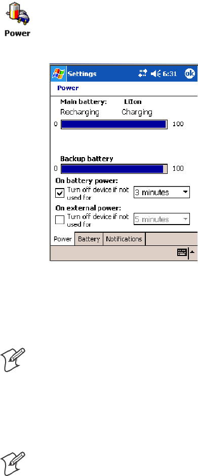
To view the status of the battery, tap Start >Settings >theSystem tab >
the Power icon > the Power tab to view the current status of both the
main AB10 battery and the backup battery. Tap ok to exit this
information.
If your computer shuts down because of low battery conditions, your com-
puter does not operate. This is done to ensure that data is protected. Al-
though the battery does protect the data against loss for several hours, you
should connect your computer to a power source when you first detect a
low battery condition.
Note: The 700 Color Computer has an internal backup super capacitor
which retains data for an average of ten minutes after the battery is re-
moved. It also shuts down the 700 Color Computer if the main battery
suddenly goes away (removed from the computer). Depending upon the
processes running, it may not have adequate power for a graceful shut
down. If so, the 700 Color performs a cold-boot the next time power is
applied.
Note: The 730 I-Safe Computer performs a cold-boot every time its main
battery is removed if it was not put in suspend mode prior to the removal.
In short, put the 700 Color Computer into a suspend (sleep) mode be-
fore you remove the main battery.
Introduction—Chapter 1
3700 Series Color Mobile Computer User’s Manual
If you have at least one device in your 700 Color Computer (radio, scan-
ner, imager, or Ethernet), the battery power fail level is set so that after the
system shuts down in a low battery condition, there is still sufficient charge
to allow the unit to remain configured, keep proper time, and maintain
DRAM (Dynamic Random Access Memory) for at least 23 to 32 hours at
room temperature if the main battery remains in the mobile computer.
The configuration and time are lost if:
SThe battery discharges beyond this level.
SThe battery is removed when the computer is not in suspend mode.
SA cold-boot (reset) is performed on the computer.
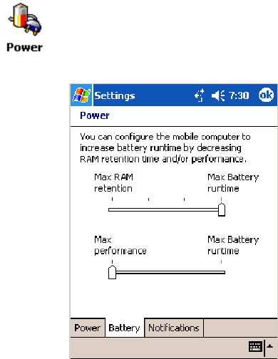
You can modify RAM maintenance in a limited way. On the 700 Color
Computer, tap Start >Settings >theSystem tab>thePower icon > the
Battery tab. Drag the top slider bar to the right to change the suspend
voltage to favor suspend time over rundown time, then click ok to exit.

IntroductionChapter —1
4 700 Series Color Mobile Computer User’s Manual
Ambient Light Sensor
Note: This information does not apply to the 730 Computer.
The ambient light sensor turns on the display lighting when conditions
warrant but automatically turns if off again as surrounding light increases.
This conserves your 700 Color battery power.
Ambient Light
Sensor Ambient Light
Sensor
This illustration shows the 700 Color Computer with a numeric keypad (left) and an alphanumeric
keypad (right).
To adjust the ambient light sensor, tap Start >Settings >theSystem tab >
the Backlight icon > the Both Power tab. Make your selections, then tap
ok to exit this applet.
Audio System
The audio system consists of the speaker, internal microphone, and the
external headset jack.
Introduction—Chapter 1
5700 Series Color Mobile Computer User’s Manual
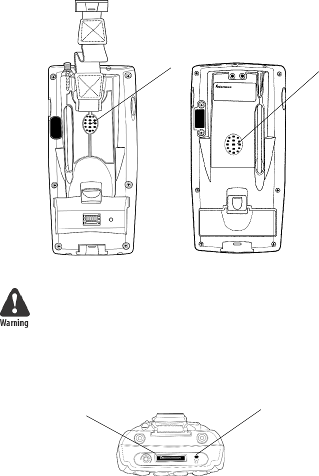
Speaker
A speaker capable of variable volume levels is located on the back of the
computer. This speaker has a transducer volume of 85 dB min at 10 CM
and a frequency range of 1–8 KHz.
Speaker Speaker
700 Color Computer 730 Computer
Warning: Do not place the speaker next to your ear when the speaker
volume is set to “Loud” (maximum), or you may damage your hearing.
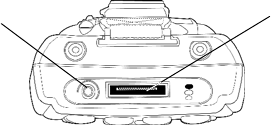
Microphone
The built-in microphone is located on the bottom of the unit next to the
Hirose docking connector.
Charging/Docking
connector Microphone
This is the bottom of the 700 Color Computer. Note that the keypad is to the bottom in this
illustration.
IntroductionChapter —1
6 700 Series Color Mobile Computer User’s Manual
External Headset Jack
The external headset jack connects a mobile phone style headset to your
mobile computer for use in noisy environments. The jack is a 2.5 mm,
three-conductor jack, with autosensing of the headset jack insertion which
disables the internal speaker and microphone. The external headset jack is
located on the bottom of the mobile computer next to the Hirose docking
connector.
Charging/Docking
connector
Headset jack
This is the bottom of the 700 Color Computer. Note that the keypad is to the bottom in this
illustration.
Introduction—Chapter 1
7700 Series Color Mobile Computer User’s Manual
Beeper
Note: Each time the 700 Color Computer is cold-booted, all default set-
tings are restored unless registry storage is enabled. See page 232 for infor-
mation on enabling the registry storage.
To learn about setting volume levels for screen taps, ActiveSync alert
noises, etc., tap Start >Help >Pocket PC Basics, then select Notifications.
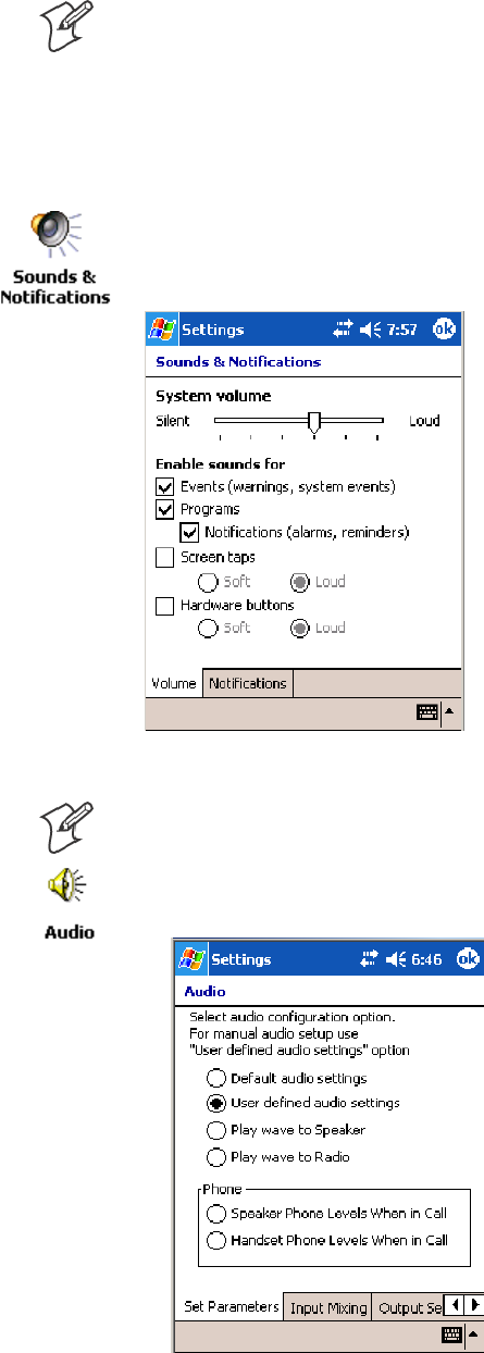
Enable the Beeper
To enable the beeper, tap Start >Settings >thePersonal tab > Sounds &
Notifications >theVolume tab. Drag the System volume slider bar to the
right of the “Silent” position. Tap ok to exit this applet.
Disable the Scanner Mute
Note: This information does not apply to the 730 Computer.
1Tap Start >Settings >theSystem tab>theAudio icon, then select
User defined audio settings.
IntroductionChapter —1
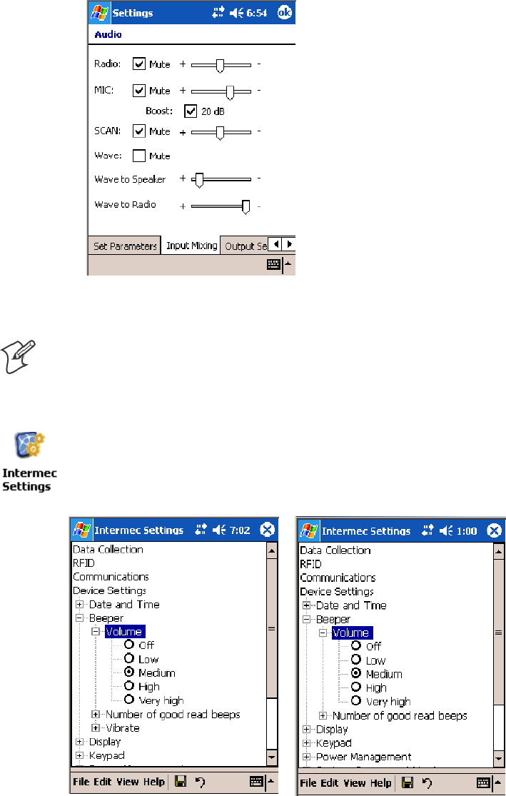
8 700 Series Color Mobile Computer User’s Manual
2Tap the Input Mixing tab, then clear the SCAN Mute box.
3Drag its slider bar to the appropriate level of loudness, with the left side
being the most loud and the right side being the most quiet. Tap ok to
exit this applet.
Select a Beeper Volume
Note: The 730 Computer does not support the laser scanner.
To determine your PSM Build version, tap Start >Programs >File Ex-
plorer >theFlash File Store folder > the PSMinfo text file.
To select a beeper volume for the 700 Color Computer, tap Start >Set-
tings >theSystem tab>theIntermec Settings icon. Tap the Device Set-
tings option, tap (+) to expand Beeper, then tap (+) to expand Volume.
Select an item, then close this option.
700 Color Screen 730 Screen
Introduction—Chapter 1
9700 Series Color Mobile Computer User’s Manual
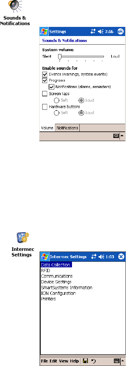
Disable the Beeper
To disable the beeper, tap Start >Settings >thePersonal tab > Sounds &
Notification >theVolume tab. Drag the System volume slider completely
to the left to “Silent,” then tap ok to exit this applet.
Intermec Settings Applet
Use the Intermec Settings applet to gather, view, and update device config-
uration settings. Information about the settings you can configure with the
Intermec Settings applet is in the Intermec Computer Command Reference
Manual (P/N: 073529) available online at www.intermec.com.
See the Data Collection Resource Kit in the Intermec Developer Library
(IDL) for information about data collection functions. The IDL is avail-
able as a download from the Intermec web site at www.intermec.com/idl.
Contact your Intermec representative for more information.
Tap Start >Settings >theSystem tab>theIntermec Settings icon to ac-
cess the applet.
IntroductionChapter —1
10 700 Series Color Mobile Computer User’s Manual
Keypads
Instructions for the keypad include the following:
700 Color Keypads
The following keypads are available for the 700 Color Computer.
Numeric keypad Alphanumeric keypad
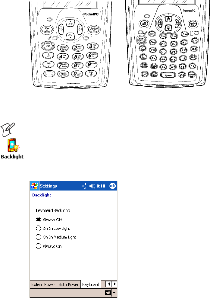
Backlight for Keypad
Note: This information does not apply to the 730 Computer.
You can configure your keypad to turn on a backlight to assist you when
you are working in low lighting. To adjust the backlight for the keypad,
tap Start >Settings >theSystem tab > Backlight. Use the left/right scroll
arrows to move to and tap the Keyboard tab. Make your selection, then
tap ok to exit this applet.

Introduction—Chapter 1
11700 Series Color Mobile Computer User’s Manual
Key Sequences
Use the following key sequences to enter characters into your 700 Color
Computer using either a numeric keypad or an alphanumeric keypad.
[Gold] or [Gold/White] Plane Keys
The [Gold] bplane key (numeric keypad) or the [Gold/White] cplane
key (alphanumeric keypad) provides you access to display controls, special
characters, and Pocket PC options.
Press the [Gold] bkey or the [Gold/White] ckey for each gold plane
key stroke you wish to make. For example to turn on the front light, press
andholdthe[Gold] bkey plus the 3key on the numeric keypad or
press and hold the [Gold/White] ckey plus the Ikey on the alphanu-
meric keypad. To turn the front light off, press the appropriate keys again.
On the next few pages are the key sequences.
Numeric Keypad
The following table lists sequences that use the [Gold] bplane key. See
Chapter 2, “Windows Mobile 2003,” for information about the Pocket PC
applications.
Press the Keys To Do This
[Gold] b3 Toggle the backlight on or off (also goes through backlight power
levels if held down)
[Gold] ba Access the Pocket PC Record application (see Note).
[Gold] b4 Access the Pocket PC Calendar application (see Note).
[Gold] b5 Access the Pocket PC Contacts application (see Note).
[Gold] b6 Access the Pocket PC Tasks application (see Note).
[Gold] b7 Move up one page.
[Gold] b8 Enter an asterisk (*).
[Gold] b9 Move down one page.
[Gold] b0 Access the Pocket PC Start menu.
[Gold] be Enter an at symbol (@).
[Gold] bK Enter a backslash (/).
[Gold] bE Enter a minus sign (–).
[Gold] bA Enter a plus sign (+).
[Gold] b→Tab to the right.
[Gold] b←Tab to the left.
[Gold] bU Increase volume
[Gold] bD Decrease volume
Note: Pocket PC applications are accessible only if configured to do so in the App Launch
portion of the Utilities applet. See page 231 for more information.

IntroductionChapter —1
12 700 Series Color Mobile Computer User’s Manual
Alphanumeric Keypad
Note: This information does not apply to the 730 Computer.
The following table lists sequences that use the [Gold/White] cplane
key. See Chapter 2, “Windows Mobile 2003,” for information about the
Pocket PC applications.
Press the Keys To Do This
[Gold/White] cI Toggle the backlight on or off (also goes through backlight
power levels if held down)
[Gold/White] cA Access the Pocket PC Record application (see Note).
[Gold/White] cB Access the Pocket PC Calendar application (see Note).
[Gold/White] cC Access the Pocket PC Contacts application (see Note).
[Gold/White] cD Access the Pocket PC Tasks application (see Note).
[Gold/White] cJ Move up one page.
[Gold/White] cG Enter an asterisk (*).
[Gold/White] cP Move down one page.
[Gold/White] cE Access the Pocket PC Start menu.
[Gold/White] cK Enter an at symbol (@).
[Gold/White] cH Enter a backslash (/).
[Gold/White] cL Enter a minus sign (–).
[Gold/White] cR Enter a plus sign (+).
[Gold/White] cl Tab to the right.
[Gold/White] cj Tab to the left.
[Gold/White] ck Increase volume
[Gold/White] cm Decrease volume
Note: Pocket PC applications are accessible only if configured to do so in the App Launch
portion of the Utilities applet. See page 231 for more information.
Alpha (Blue) Plane Keys
The alphabet can be entered with either the numeric keypad or the alpha-
numeric keypad. Below and on the next page are the key sequences.
Numeric Keypad
When you press F, the Scanning/Alpha LED (C) shows ‘red’ for
the Alpha mode. The keypad stays in Alpha mode until you press F.
To type a lowercase ‘c,’ press F222(the [2] key three
times). To type a letter on the same key as the last letter entered, wait two
seconds, then enter the correct series of keystrokes to create the next letter.
WhileyouareintheAlphamodeandyoupress1to initiate the CAPS
mode, you will render a CAPS LOCK until you press 1again. Once
you are in CAPS mode, you stay in CAPS until it is pressed again.
Press 0to enter a space.

Introduction—Chapter 1
13700 Series Color Mobile Computer User’s Manual
To Enter Press the Keys To Enter Press the Keys
aF2 AF12
bF22 BF122
cF222 CF1222
dF3 DF13
eF33 EF133
fF333 FF1333
gF4 GF14
hF44 HF144
iF444 IF1444
jF5 JF15
kF55 KF155
lF555 LF1555
mF6 MF16
nF66 NF166
oF666 OF1666
pF7 PF17
qF77 QF177
rF777 RF1777
sF7777 SF17777
tF8 TF18
uF88 UF188
vF888 VF1888
wF9 WF19
xF99 XF199
yF999 YF1999
zF9999 ZF19999
Alphanumeric Keypad
When you press d, the Scanning/Alpha LED (C) is ‘red’ to indicate
Alpha mode. The keypad stays in Alpha mode until you press dagain.
If you want to type a lowercase ‘c,’ press dC.Ifyouwantanuppercase
“C,” press and hold the gkey, then press C.
Press bto enter a space.
To Enter Press the Keys To Enter Press the Keys
adA AdgA
bdB BdgB
cdC CdgC
ddD DdgD

IntroductionChapter —1
14 700 Series Color Mobile Computer User’s Manual
Press the KeysTo EnterPress the KeysTo Enter
edE EdgE
fdF FdgF
gdG GdgG
hdH HdgH
idI IdgI
jdJ JdgJ
kdK KdgK
ldL LdgL
mdM MdgM
ndN NdgN
odO OdgO
pdP PdgP
qdQ QdgQ
rdR RdgR
sdS SdgS
tdT TdgT
udU UdgU
vdV VdgV
wdW WdgW
xdX XdgX
ydY YdgY
zdZ ZdgZ
LEDs
The battery status LED Band the scanning/keypad shift and notifica-
tion LED Cturn red, green, or yellow.
Battery Status LED
LED Color and Action Description
Steady Green Battery is more than 95% charged and unit is on charger.
Blinking Red Battery is low. The blinking speed increases as the battery’s power gets increasingly lower.
Red Main battery is low; or if charging, remains red until your 700 Color Computer reaches
95% charge status.
Yellow The700ColorComputerisonachargingsource and there is no battery pack installed.
The mobile computer may also be out of the charging range of 32° to 122° F (0° to 50°
C). When back in range, charging resumes and the LED changes to red or green.
Alternating Red/Yellow Replace the battery pack.
Introduction—Chapter 1
15700 Series Color Mobile Computer User’s Manual
Scanning/Keypad Shift and Notification LED
LED Color and Action Description
Momentary Green Indicates a good scan.
Blinking Green Indicates the scanner is initializing.
Steady Red Indicates the keypad is shifted to Alpha (Blue) and the 700 Color Computer is turned on.
Blinking Red Indicates the WAN (GPRS or CDMA) radio is on when the 700 Color Computer is in
suspend mode. Also indicates when the WAN radio is initialized on 761 Computers.
Yellow When the keypad is in alpha mode, the LED temporarily switches from red to yellow to
indicate a good scan. This also indicates a Calendar or Task activity occurred.
Modem Support
The 700 Color Computer has the following modem options:
SAD16 modem dock that provides charging and includes a built-in mo-
dem and a serial port between which an application can switch.
SAA8 snap-on modem, a stand-alone product, that attaches to the bot-
tom of your 700 Color Computer. Note that you cannot place this mo-
dem in a dock, printer, or other devices. Contact your Intermec repre-
sentative for more information.
PSM Build Version
The Persistent Storage Manager (PSM) is an area of storage which is em-
bedded in a section of the system’s FLASH memory. This storage area is
not erased during a cold-boot. It may, however, be erased during the re-
flashing process. In addition to storing applications and data files, you do
have the option to store a persistent registry to the PSM region.
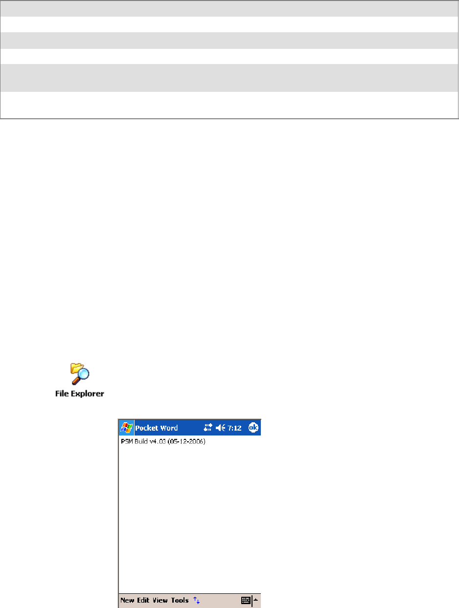
To determine what PSM Build is on your 700 Color Computer, tap Start
>Programs >File Explorer. Access the Flash File Store folder from the
My Device root directory, then tap the PSMinfo text file. Take note of
your information, then tap ok to exit.
IntroductionChapter —1
16 700 Series Color Mobile Computer User’s Manual
Resetting Your 700 Color Computer
Performing a Warm-Boot
Performing a warm-boot may be necessary to correct conditions where an
application stops responding to the system. It does, however, unload all
running programs.
Press and hold the I/O key for about ten seconds, then the 700 Color
Computer continues from the screen you were at before you performed
the warm-boot.
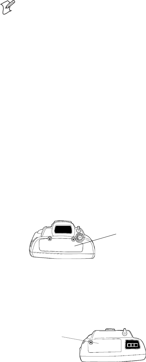
Performing a Cold-Boot
In some cases where the 700 Color Computer completely stops respond-
ing, it may be necessary to perform a cold-boot. Because this may result in
data loss, this procedure is not recommended unless all other recovery
methods have failed.
Note: This deletes all programs and data stored in RAM including the Ob-
ject Store. Make sure data is backed up to your host computer or a storage
card before performing a cold-boot.
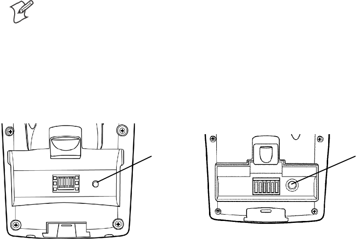
1Release the lower clip of the hand strap.
2Remove the battery pack.
3Press the Reset button.
4Reinstall the battery pack.
Reset button Reset button
This illustration shows the back of the 700 Color Computer on the left and of the 730 Computer on the right.
Introduction—Chapter 1
17700 Series Color Mobile Computer User’s Manual
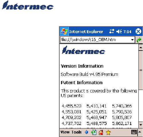
Software Build Version
To check to see if your 700 Color Computer has the latest software build,
select Start >Internet Explorer >theIntermec logo. The latest software
build version is displayed beneath the Version Information title.
Software Tools
The following Intermec software tools are available as free downloads:
SmartSystemstFoundation Console (www.intermec.com/SmartSystems)
This tool includes a management console that provides a default method
to configure and manage Intermec devices “out-of-the-box,” without the
purchase of additional software licenses. This is for anyone who must con-
figure and deploy multiple devices or manage multiple licenses.
Intermec Resource Kits (www.intermec.com/IDL)
Resource Kits provide tools that build applications using the features of
Intermec devices. Resource kits include: Bluetooth, Communications,
Data Collection, Device Settings, Mobile Gadgets, Printing, and RFID.
This is for anyone who develops software for the 700 Color Computer.
IntroductionChapter —1
18 700 Series Color Mobile Computer User’s Manual
Storage Media
Note: MultiMediaCards (MMCs) are not supported.
Storage Cards Available
CompactFlash Cards
On 700 Color Computers, the CompactFlash card slot accepts either a
storage card or the 802.11b or 802.11b/g radio, which is factory-installed
and cannot be removed. The 730 Computer does not support Compact-
Flash storage cards.
Secure Digital Cards
The Secure Digital card slot accepts storage cards only.
SIM Cards
Subscriber Identification Module (SIM) cards are used on all 700 Color
Computers shipped with WAN GPS/GPRS radios. The model number
calls out which of the 700 Color Computers are GPRS/GPS devices in the
seventh or eighth place, such as “G2” for European GPRS and “G4” for
US GPRS. Contact your Intermec representative for more information on
SIM cards.
700 Color Computers
The 700 Color Computer supports CompactFlash, Secure Digital, and
SIM storage cards. To access either card slot, locate the access door at the
top of the 700 Color Computer, remove its two screws, then remove the
door.
Storage Media
Access Door
Note that the keypad is to the bottom for this 700 Color Computer.
730 Computers
The 730 Computer only supports the Secure Digital storage card. The
CompactFlash card slot is embedded in the 730 Computer and cannot be
removed. To access the Secure Digital card slot, locate the access door at
the top of the 730 Computer, remove its screws, then remove the door.
Storage Media
Access Door
Note that the keypad is to the bottom for this 730 Computer.
Introduction—Chapter 1
19700 Series Color Mobile Computer User’s Manual
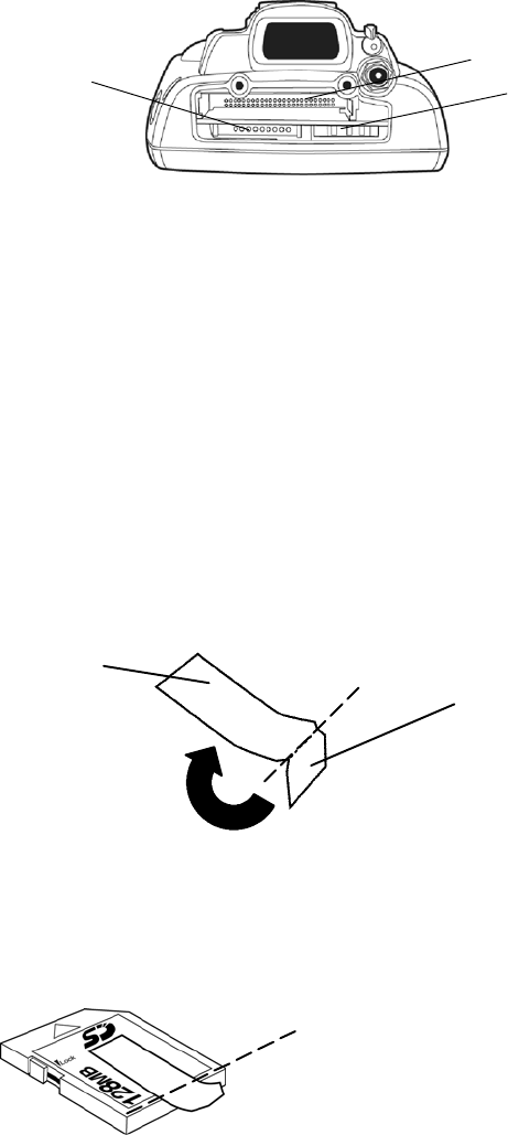
Internal Card Slots
Below is a view of the various card slots within your 700 Color Computer.
Note that the 730 Computer only allows access to the Secure Digital and
SIM card slots.
SThe CompactFlash card goes into the top card clot.
SThe Secure Digital card would go into the bottom left card slot.
SThe SIM card goes into the bottom right card slot.
CompactFlash card slot
Secure Digital
card slot SIM card slot
This illustration is of the 700 Color Computer with the keypad on the bottom.
Inserting the Storage Card
The Secure Digital storage card, as ordered from Intermec Technologies,
come with acrylic adhesive pull tabs. If you are using a storage card that
you plan to remove from the 700 Color Computer, this tab can make its
removal easier.
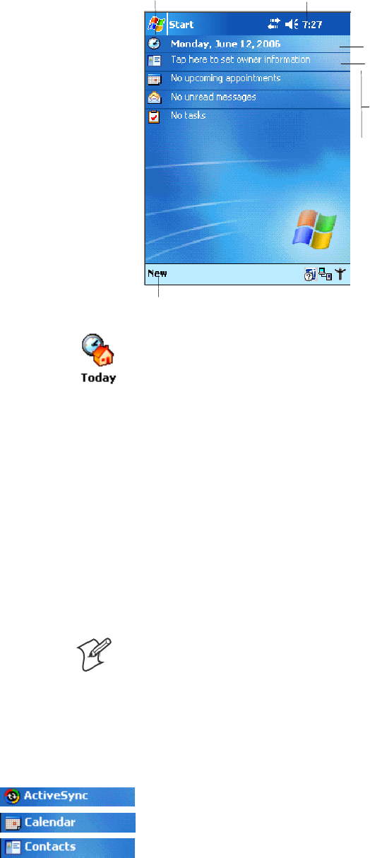
Do the following to attach the tab to your storage card. Note that the pull
tab has divots cut into either side, towards the shorter end. Use these div-
otsasaguide.
1Completely peel the paper off the short end of the tab. Partially pull the
paper off the long end of the tab away from the divots. Fold the short
end under, at the divots, to stick to itself.
Short end
of pull tab
Long end
of pull tab
Fold line
at divots
2Align the folded edge of the pull tab where there is no adhesive with the
bottom end of the storage card. Peel away the rest of the paper from the
long end, then firmly press down the remaining adhesive area of the tab
onto the storage card.
Align the folded end with this
edge of the storage card

IntroductionChapter —1
20 700 Series Color Mobile Computer User’s Manual
3Insert the storage card, with the contacts facing the keypad, into your
700 Color Computer to ensure that no adhesive is exposed once the tab
is placed.
Keypad facing down
Vibrator
Note: This information does not apply to the 730 Computer.
If your 700 Color Computer is built with an imager or scanner and the
vibrator is disabled, do the following instructions to enable the vibrator. If
you are not able to enable the vibrator, then contact Customer Support.
For information about setting volume levels for screen taps, ActiveSync
alert noises, etc., tap Start >Help >Pocket PC Basics, then select
Notifications.
Note: Each time the 700 Color Computer is cold-booted, all default set-
tings are restored.
Do the following to enable the vibrator for the 700 Color Computer. Tap
Start >Settings >theSystem tab>theIntermec Settings icon. Tap the
Device Settings option, tap (+) to expand Beeper, then tap (+) to expand
Vibrate. Select an item, then close this option.
Note: Information about the settings you can configure with the Intermec
Settings applet is described in the Intermec Computer Command Reference
Manual. The online manual is available from the Intermec web site at
www.intermec.com

Introduction—Chapter 1
21700 Series Color Mobile Computer User’s Manual
Wireless Network Support
Radios are installed at the factory and cannot be installed by a user. The
700 Color Computer must be serviced to install or replace radios. Contact
your Intermec representative for more information. See Chapter 4, “Net-
work Support” for information about supported radios.
Note: Changes or modifications not expressly approved by Intermec could
void the user’s authority to operate the equipment.
Accessories
The following accessories are available for the 700 Color Computer. Note
that this is not a complete list. Contact your Intermec representative for in-
formation about these and other accessories that are not in this list.
Accessory Descriptions 700 Color 730 Computer
AA8 Snap-On Modem X
AA9 DEX Adapter X
AA10 Long Range Tethered Scanning Adapter (3.3v to 5v) X
AC15 Single Battery Charger X
AC16 Quad Battery Charger XX
AD15 Single Dock Charger with USB and Ethernet XX**
AD16 Modem Dock XX
AD17 Multidock — Charge Only (holds four 700 Computers) X X
AD18 Multidock Charging with Ethernet support (holds four units) X
AH5 Standard Scan Handle Option X X
AV7 Vehicle Dock XX
** No Ethernet Support
Physical and Environmental Specifications
Use this section to locate technical information about the 700 Color Com-
puter and its available features and options.
Cisco Compatible Extensions: 730 740, 741, 750, 751, 760, 761
Version 1 LEAP, CKIP, VLAN X
Version 2 future
Display: 730 740, 741, 750, 751, 760, 761
Transflective TFT all-light readable color display
with LED backlight
Transflective
Pixels 240x320 240x320

IntroductionChapter —1
22 700 Series Color Mobile Computer User’s Manual
740, 741, 750, 751, 760, 761730Display:
Diagonal 89mm (3.5 in) 97mm (3.8 in)
Colors 64 K 256 K
Environmental: 730 740, 741, 750, 751, 760, 761
Operating Temperature -10° to 55°C (14° to 131°F) -20° to 60°C (-4° to 140°F)
Storage Temperature -20° to 60°C (-4° to 140°F) -20° to 60°C (-4° to 140°F)
Relative Humidity 5% to 95% noncondensing 5% to 95% noncondensing
Rain and Dust Resistance IP54 compliant IP64 compliant
Drop Specifications 1.2m(4’)drop,26timesonconcrete 5’ drop, 26 times onto concrete
Expansion Slots: 730 740, 741, 750, 751, 760, 761
Secure Digital (SD) XX
CompactFlash (CF) Type II X
Integrated Scanner Options: 730 740, 741, 750, 751, 760, 761
Area Imager X
Linear Imager X X
1D Laser X
PDF 417 Laser X
Integrated Wireless: 730 740, 741, 750, 751, 760, 761
802.11b (Wi-Fi® certified) WLAN (802.11b) LAN (802.11b/g)
WAN: GSM/GPRS, CDMA/1xRTT
Bluetoothtcompatible module X X
Keypad Options: 730 740, 741, 750, 751, 760, 761
Numeric XX
Full Alphanumeric X
Memory and Storage: 730 740, 741, 750, 751, 760, 761
RAM Memory 64 MB 64 MB (128 MB optional)
Flash ROM 64 MB, includes ROM folder for
application storage
64 MB, includes ROM folder for
application storage
Microprocessor: 730 740, 741, 750, 751, 760, 761
Intel® XScaletPXA255 Application
Processor, 400 MHz Intel® XScaletProcessor, 400 MHz
AA8 Modem: 730 740, 741, 750, 751, 760, 761
Optional V.90 modem snaps on
V.92 docking options
X

Introduction—Chapter 1
23700 Series Color Mobile Computer User’s Manual
Operating System: 730 740, 741, 750, 751, 760, 761
Microsoft® Windows® Mobile soft-
ware for Pocket PC
X X
Physical Dimensions: 730 740, 741, 750, 751, 760, 761
Length 178 mm (7.0 in) 191 mm (7.53 in)
Width 89 mm (3.5 in) 90 mm (3.5 in)
Height 38 mm (1.5 in) 50 mm (1.97 in)
Weight 420 g (15 oz) 483-568 g (17-20 oz)
depending on options
Power: 730 740, 741, 750, 751, 760, 761
Battery Type AB10 Lithium-Ion (LiIon), 3.6V, (1 x
2400 mAh cells), customer-replaceable
LiIon, 7.2V, (2 x 2000 mAh cells),
customer-replaceable
Battery Capacity 8.64 Watt-hours 14.4 Watt-hours
Battery Life 6-10 hours, application dependent 8-12 hours, application dependent
Recharging Time 4hours 4hours
Regulatory Approvals: 730 740, 741, 750, 751, 760, 761
FCC Part 15 Class B XX
UL Listing X X
CE Mark XX
CB Report X
Standard Communications: 730 740, 741, 750, 751, 760, 761
RS232 XX
USB XClient
IrDA 1.1 (115 kbps) XX
10 Base-T Ethernet X
IntroductionChapter —1
24 700 Series Color Mobile Computer User’s Manual

25700 Series Color Mobile Computer User’s Manual
Windows Mobile 2003
2
This chapter introduces Microsoft Windows Mobile 2003 for Pocket PC.
While using your 700 Color Computer, keep these key points in mind:
STap Start on the navigation bar, located at the top of the screen, to
quickly move to programs, files, and settings. Use the command bar at
the bottom of the screen to perform tasks in programs. The command
bar includes menus, icons, and the onscreen keyboard.
STap and hold an item to see a pop-up menu containing a list of actions
you can perform. Pop-up menus give you quick and easy access to the
most common actions.
Note: “700 Color” pertains to 740, 741, 750, 751, 760, and 761 Com-
puters unless otherwise noted.
Below is a list of Windows Mobile 2003 components described in this
chapter. Tap Start >Help on your 700 Color Computer to find additional
information on Windows Mobile components.
Windows Mobile 2003 Components
Microsoft ActiveSync Client (page 41)
Microsoft Pocket Outlook (page 42)
Pocket Word (page 68)
Pocket Excel (page 71)
MSN Messenger (page 73)
Windows Media Player for Pocket PC (page 76)
Microsoft Reader (page 77)
Pocket Internet Explorer (page 79)

Windows Mobile 2003Chapter —2
26 700 Series Color Mobile Computer User’s Manual
Software Builds
Go to “Software Build Version” on page 17 to determine which Intermec
build of Windows Mobile 2003 is on your unit.
Where to Find Information
This chapter describes your 700 Color Computer hardware, provides an
overview of the programs on your 700 Color Computer, and explains how
to connect your 700 Color Computer to a desktop, a network, or the In-
ternet. For instructions on setting up your 700 Color Computer and
installing ActiveSync, see the Quick Start Guide. The following is a guide
to more information to assist you use your 700 Color Computer.
For information on: See this source:
Programs on your mobile computer. This chapter and mobile computer Help. To view Help,
tap Start >Help.
Additional programs that can be installed on the mobile
computer.
The Windows Mobile Companion CD.
Connecting to and synchronizing with a desktop. The Quick Start Guide or AutoSync Help on your desk-
top. To view Help, click Help >Microsoft ActiveSync
Help.
Last-minute updates and detailed technical information. The Read Me files, located in the Microsoft ActiveSync
folder on the desktop and on the Windows Mobile Com-
panion CD.
Up-to-date information on your Windows Mobile. www.microsoft.com/windowsmobile/resources/commu-
nities/default.mspx
Windows Mobile and many of the technologies supported by the 700 Col-
or Computer are not from Intermec. Many of the utilities and features on
a Windows Mobile device come directly from Microsoft without any mod-
ification from Intermec. There may be certain Microsoft-specific issues
that Intermec would not be able to support, so contact our front-line sup-
port personnel to determine the best source of assistance.
Use these URLs for additional information about Microsoft Windows
Mobile (Pocket PC):
Smsdn.microsoft.com/support/
Ssupport.microsoft.com/
Snews://news.microsoft.com (a free support option)
Basic Skills
Learning to use your 700 Color Computer is easy. This section describes
the basic concepts of using and customizing your 700 Color Computer.
Today Screen
When you turn on your 700 Color Computer for the first time each day
(or after four hours of inactivity),youseetheToday screen. You can also
Windows Mobile 2003—Chapter 2
27700 Series Color Mobile Computer User’s Manual
display it by tapping the Start flag (shown left) and then Today.Onthe
Today screen, you can see important information for the day.
Tap to create a new item.
Your day at a glance. Tap
to open the associated
program.
Tap to change owner information.
Tap to change date and time.
Tap and hold to change time format.Tap to start a program.
To customize what is displayed on the Today screen, including the back-
ground image, tap Start >Settings >thePersonal tab > Today.
Status icons display information such as low batteries or when the 700
Color Computer is connected to a desktop or to the Internet. You can tap
an icon to open the associated setting or program.
Programs
You can switch from one program to another by selecting it from the Start
menu. (You can customize which programs you see on this menu. For
information, see “Adjusting Settings” on page 38.) To access some
programs, tap Start >Programs, and then the program name.
You can also switch to some programs by pressing a program icon. Your
700 Color Computer has one or more program icons located on the front
or side of the computer. The icons on the icons identify the programs to
which they switch.
Note: Some programs have abbreviated labels for check boxes and drop-
down menus. To see the full spelling of an abbreviated label, tap and hold
the stylus on the label. Drag the stylus off the label so that the command is
not carried out.
The following is a partial list of programs that are on your 700 Color
Computer. Look on the Windows Mobile Companion CD for additional
programs that you can install onto your 700 Color Computer.
Synchronize information between your 700 Color Computer and desktop.
Keep track of your appointments and create meeting requests.
Keep track of your friends and colleagues.
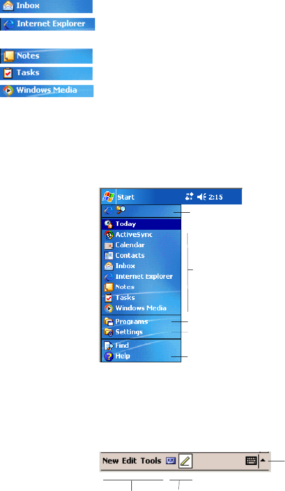
Windows Mobile 2003Chapter —2
28 700 Series Color Mobile Computer User’s Manual
Send and receive e-mail messages.
Browse Web and WAP (Wireless Application Protocol) sites, and down-
load new programs and files from the Internet.
Create handwritten or typed notes, drawings, and recordings.
Keep track of your tasks.
Play digital audio and video files that are stored on your 700 Series Com-
puter or on a network.
Navigation Bar and Command Bar
The navigation bar is located at the top of the screen. It displays the active
program and current time, and allows you to switch to programs and close
screens.
Taptoswitchtoaprogram.
Tap to see more programs.
Taptoswitchtoaprogram
that you recently used.
Tap to change device settings.
Tap to see a Help topic
for the current screen.
Use the command bar at the bottom of the screen to perform tasks in pro-
grams. The command bar includes menu names, icons, and the Input
Panel icon. To create a new item in the current program, tap New.Tosee
the name of an icon, tap and hold the stylus on the icon. Drag the stylus
off the icon so that the command is not carried out.
Taptoselect
menu commands.
Tap to display the input panel.
Taptoselect
icon commands.
Pop-up Menus
Use pop-up menus to quickly perform an action on an item. For example,
you can use a pop-up menu to delete or make a copy of an item. To access
a pop-up menu, tap and hold the item on which you want to perform the
action. When the menu appears, tap the action you want to perform, or
tap anywhere outside the menu to close the menu without performing the
action.
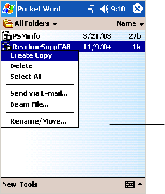
Windows Mobile 2003—Chapter 2
29700 Series Color Mobile Computer User’s Manual
Tap and hold to display the
pop-up menu.
Lift the stylus and tap the action
you want.
Tap outside the menu to
close it without performing
an action.
Notifications
When you have something to do, your device notifies you in a variety of
ways. For example, if you have set up an appointment in Calendar, an e-
mail message arrives, or a friend sends you an instant message, you are no-
tified in any of the following ways:
SA message box appears on the screen.
SA sound, which you can specify, is played.
SA light flashes on your 700 Color Computer.
SThe 700 Color Computer vibrates.
You can choose the notification types.
Entering Information
You can enter information on your 700 Color Computer in several ways,
depending on the type of device you have and the program you are using:
SSynchronizing
Using Microsoft ActiveSync, synchronize or copy information between
your desktop and 700 Color Computer. For more information on Acti-
veSync, see ActiveSync Help on your desktop.
STyping
Using the input panel, enter typed text into the 700 Color Computer.
You can do this by tapping keys on the onscreen keyboard or by using
handwriting recognition software.
SWriting
Using the stylus, write directly on the screen.
SDrawing
Using the stylus, draw directly on the screen.
SRecording
Create a stand-alone recording or embed a recording into a document or
note.

Windows Mobile 2003Chapter —2
30 700 Series Color Mobile Computer User’s Manual
Use the input panel to enter information in any program on your 700
Color Computer. You can either type using the onscreen keyboard or
write using Block Recognizer,Letter Recognizer,orTranscriber.Ineither
case, the characters appear as typed text on the screen.
To show or hide the input panel, tap the Input Panel icon. Tap the arrow
next to the Input Panel icon to see your choices.
Tap to see your choices.
Input Panel icon.
Select an input method.
When you use the input panel, your 700 Color Computer anticipates the
word you are typing or writing and displays it above the input panel.
When you tap the displayed word, it is inserted into your text at the inser-
tion point. The more you use your 700 Color Computer, the more words
it learns to anticipate.
To change word suggestion options, such as the number of words sug-
gested at one time, tap Start >Settings >thePersonal tab > Input >the
Word Completion tab.
Tap a text box to display
the currently selected
input panel.
To enter characters, tap
them on the onscreen
keyboard.
Tap to insert anticipated
word.
Typing With the Onscreen Keyboard
Tap the input panel arrow, then tap Keyboard.Onthesoftkeyboardthat
is displayed, tap the keys with your stylus.
STo type lowercase letters, tap the keys with the stylus.
STo type a single uppercase letter or symbol, tap the Shift key. To tap
multiple uppercase letters or symbols, tap the CAP key.
STo convert a letter to uppercase, tap and hold the stylus on the letter
and drag up.
STo add a space, drag the stylus to the right across at least two keys.
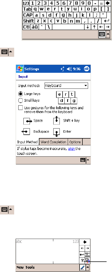
Windows Mobile 2003—Chapter 2
31700 Series Color Mobile Computer User’s Manual
STo backspace one character, drag the stylus to the left across at least two
keys.
STo insert a carriage return, tap and hold the stylus anywhere on the key-
board and drag down.
To use larger keys, tap the input panel arrow, tap Options, select “Key-
board” from the Input method drop-down list, then select Large keys.
Using Block Recognizer
Character recognition software gives you a fast and easy method for enter-
ing information in any program on your 700 Color Computer. Letters,
numbers, and punctuation you write are translated into typed text.
Tap the input panel arrow, then tap Block Recognizer. Write a letter in
the box. When you write a letter, it is converted to typed text onscreen.
For specific instructions on using Block Recognizer, with Block Recogniz-
er open, tap the question mark next to the writing area.
Tap for assistance.
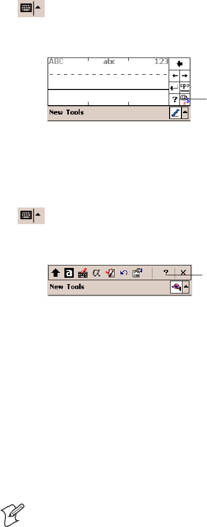
Windows Mobile 2003Chapter —2
32 700 Series Color Mobile Computer User’s Manual
Using Letter Recognizer
With Letter Recognizer, you can write letters using the stylus just as you
would on paper.
Tap the input panel arrow, then tap Letter Recognizer. Write a letter in
the box. When you write a letter, it is converted to typed text that appears
on the screen. For specific instructions on using Letter Recognizer, with
Letter Recognizer open, tap the question mark next to the writing area.
Tap for assistance.
Using Transcriber
With Transcriber, you can write anywhere on the screen using the stylus
just as you would on paper. Unlike Letter Recognizer and Block Recogniz-
er, you can write a sentence or more of information. Then, pause and let
Transcriber change the written characters to typed characters.
Tap the input panel arrow, then tap Transcriber.Tapok,thenwriteany-
where on the screen. For specific instructions on using Transcriber, with
Transcriber open, tap the question mark in the lower, right-hand corner of
the screen.
Tap for assistance.
Selecting Typed Text
If you want to edit or format typed text, you must select it first. Drag the
stylus across the text you want to select. You can cut, copy, and paste text
by tapping and holding the selected words, then tapping an editing com-
mand on the pop-up menu, or tapping the command on the Edit menu.
Writing on the Screen
In any writing program, such as the Notes program, and in the Notes tab
in Calendar, Contacts, and Tasks, you can use your stylus to write directly
on the screen. Write the way you do on paper. You can edit and format
what you have written and convert the information to text at a later time.
STap the Pen icon to switch to writing mode. This action displays lines
on the screen to help you write.
Note: Some programs that accept writing may not have the Pen icon. See
the documentation for that program to find out how to switch to writing
mode.
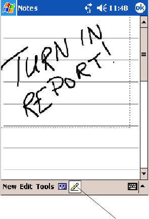
Windows Mobile 2003—Chapter 2
33700 Series Color Mobile Computer User’s Manual
Tap to use your stylus like a pen.
Selecting the Writing
If you want to edit or format writing, you must select it first.
1Tap and hold the stylus next to the text you want to select until the in-
sertion point appears.
2Without lifting, drag the stylus across the text you want to select.
If you accidentally write on the screen, tap Tools >Undo and try again.
You can also select text by tapping the Pen icon to deselect it and then
dragging the stylus across the screen.
You can cut, copy, and paste written text in the same way you work with
typed text: tap and hold the selected words and then tap an editing com-
mand on the pop-up menu, or tap the command on the Edit menu.
Converting Writing to Text
You can convert words you write in print or cursive to text by tapping
Tools >Recognize. If a word is not recognized, it keeps its original form.
If you want to convert only certain words, tap Pen to disable the writing
function, tap twice over the word or phrase to highlight, then tap Tools >
Recognize.
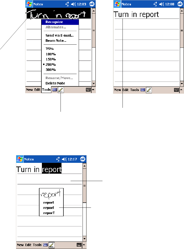
Windows Mobile 2003Chapter —2
34 700 Series Color Mobile Computer User’s Manual
Tap to disable the pen function.
Select the text you want to
convert and tap Recognize
on the pop-up menu.
The writing is turned
into text.
If the conversion is incorrect, you can choose different words from a list of
alternates or return to the original writing. To do so, tap and hold the
incorrect word (tap one word at a time). On the pop-up menu, tap
Alternates. Tap the word use from the menu with a list of alternate words,
or tap the writing at the top of the menu to return to the original writing.
Tap to return to your
original writing.
Or, tap the word you
want to use.
Tips for getting good recognition:
SWrite neatly.
SWrite on the lines and draw descenders below the line. Write the cross
of the “t” and apostrophes below the top line so they are not confused
with the word above. Write periods and commas above the baseline.
SFor better recognition, try increasing the zoom level to 300% by using
the Tools menu. Recognition does not work well below a 150% zoom
level.
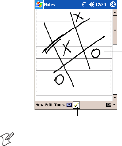
Windows Mobile 2003—Chapter 2
35700 Series Color Mobile Computer User’s Manual
SWrite the letters of a word closely and leave big gaps between words so
that the 700 Color Computer can easily tell where words begin and end.
SHyphenated words, foreign words that use special characters such as ac-
cents, and some punctuation cannot be converted.
SIf you add writing to a word to change it (such as changing a “3” to an
“8”) after you attempt to recognize the word, the writing you add is not
included if you attempt to recognize the writing again.
Drawing on the Screen
You can draw on the screen in the same way that you write on the screen.
The difference between writing and drawing on the screen is how you se-
lect items and how they are edited. For example, you can resize selected
drawings, while you cannot resize writing.
Creating a Drawing
SCross three ruled lines on your first stroke. A drawing box appears. Sub-
sequent strokes in or touching the drawing box become part of the dra-
wing. Drawings that do not cross three ruled lines are treated as writing.
The drawing box indicates
the boundaries of the
drawing.
Pen icon.
Note: You may want to change the zoom level so that you can more easily
work on or view your drawing. Tap Tools and then a zoom level.
Selecting a Drawing
Ifyouwanttoeditorformatadrawing,youmustselectitfirst.
STap and hold the stylus on the drawing until the selection handle ap-
pears. To select multiple drawings, deselect the Pen icon and then drag
to select the drawings you want.
You can cut, copy, and paste selected drawings by tapping and holding the
selected drawing and then tapping an editing command on the pop-up
menu, or by tapping the command on the Edit menu. To resize a drawing,
make sure the Pen icon is not selected, and drag a selection handle.
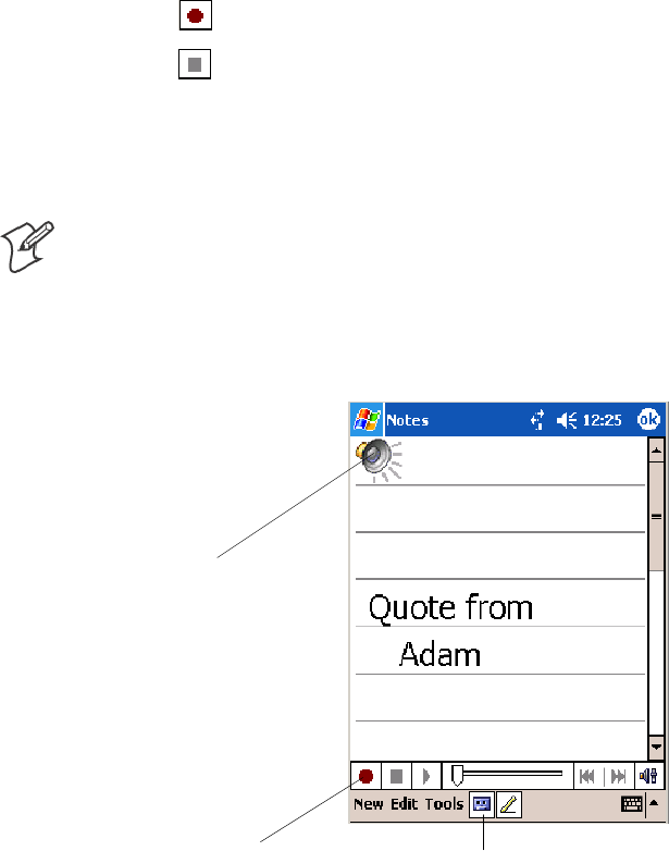
Windows Mobile 2003Chapter —2
36 700 Series Color Mobile Computer User’s Manual
Recording a Message
In any program where you can write or draw onscreen, you can also cap-
ture thoughts, reminders, and phone numbers by recording a message.
In the Inbox program, you can add a recording to an e-mail message. In
Calendar, Tasks, and Contacts, you can include a recording in the Notes
tab. In the Notes program, you can create a stand-alone recording or add a
recording to an open note.
1Hold the 700 Color Computer’s microphone near your mouth or
source of sound.
2Tap and make your recording.
3Tap when finished. If you are recording in an open note, an icon
appears in the note. If you are creating a stand-alone recording, it ap-
pears in the note list.
4To play a recording, tap the recording icon in the open note or tap the
recording in the note list.
Note: To quickly create a recording, hold down the Record hardware
icon. When you hear the beep, begin your recording. Release the icon
when you are finished. The new recording is stored in the open note or as
a stand-alone recording if no note is open.
To play a recording, tap it in the list or tap its icon in the note.
Indicates an embedded
recording.
Tap to begin recording. Tap to show or hide the Recording toolbar.
Using My Text
When using Inbox or MSN Messenger, use My Text to quickly insert pre-
set or frequently used messages into the text entry area. To insert a mes-
sage, tap My Text and tap a message.
STo add common messages, tap My Text, then a desired message.
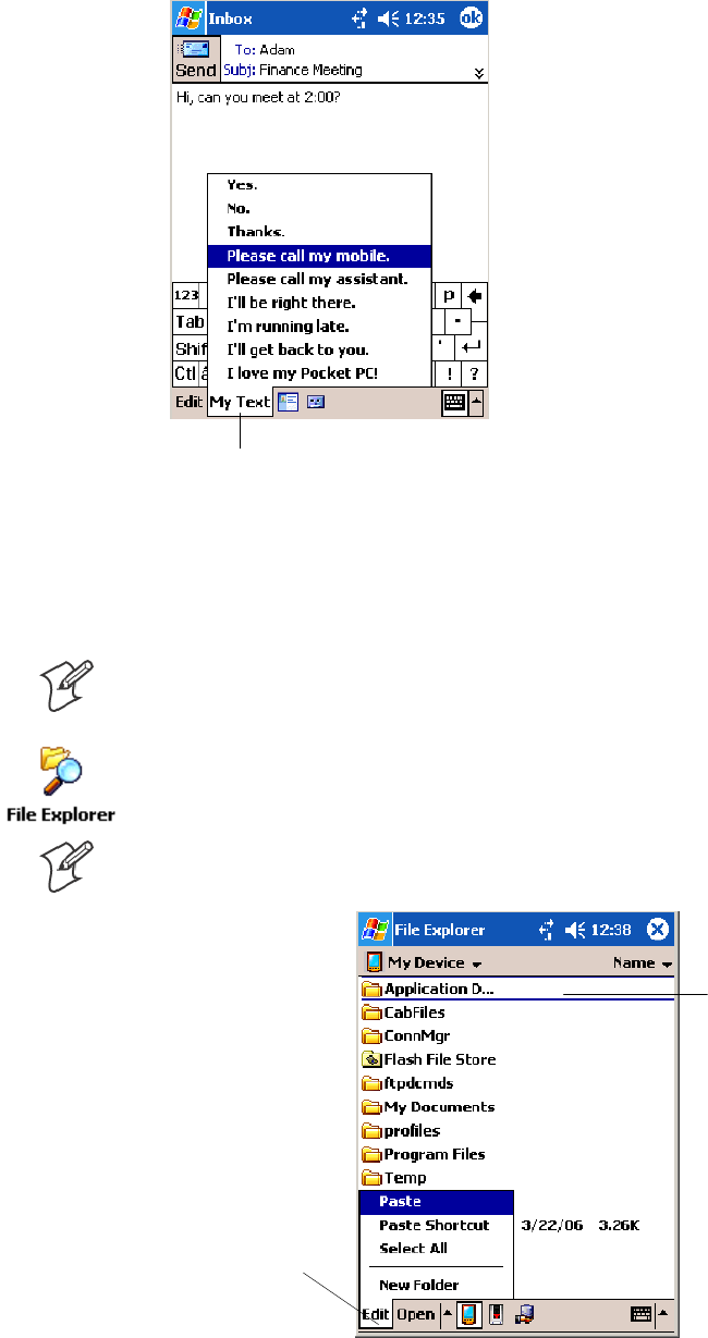
Windows Mobile 2003—Chapter 2
37700 Series Color Mobile Computer User’s Manual
STo edit a My Text message, tap Tools >Edit My Text Messages.Tap
the message to edit and enter new text at the bottom of the screen.
Tap to select a prewritten message.
Finding and Organizing Information
The Find feature helps you to quickly locate information.
Tap Start >Find. Enter the text you want to find, select a data type, and
then tap Go to initiate the search.
Note: To quickly find information that is taking up storage space on your
700 Color Computer, select Larger than 64 KB in Type.
Use the File Explorer to find files on your 700 Color Computer and to
organize these files into folders. Tap Start >Programs >File Explorer.
Note: You can move files in File Explorer by tapping and holding the item
you want to move, and then tapping Cut or Copy and Paste on the menu.
Tap the folder name
to open it.
Tap New Folder to
create a new folder.
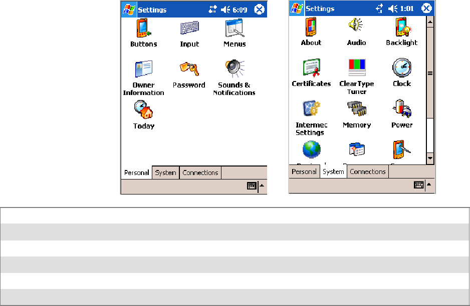
Windows Mobile 2003Chapter —2
38 700 Series Color Mobile Computer User’s Manual
Customizing Your 700 Color Computer
You can customize your 700 Color Computer by adjusting settings and
installing additional software.
Adjusting Settings
You can adjust settings to suit the way you work. To see available options,
tap Start >Settings > either the Personal tab or the System tab located at
the bottom of the screen. You might want to adjust the following:
Menus:To customize the Start menu, and to enable a pop-up menu from the New icon.
Owner Information:Toenteryourcontactinformation.
Password:To limit access to your 700 Color Computer.
Today:To customize the look and information displayed on the Today screen.
Clock:To change the time or to set alarms.
Power:To maximize battery life.
Adding or Removing Programs
Programs added to your 700 Color Computer at the factory are stored in
ROM (Read Only Memory). You cannot remove this software, and you
cannot accidentally lose ROM contents. ROM programs can be updated
using special installation programs with a *.XIP extension. All other pro-
grams and data files added to your 700 Color Computer after factory
installation are stored in RAM (Random Access Memory).
You can install any program created for your 700 Color Computer, as long
as your 700 Color Computer has enough memory. The most popular
place to find software for your 700 Color Computer is on the Windows
Mobile Web site (www.microsoft.com/windowsmobile/resources/commu-
nities/default.mspx).
Adding Programs Using ActiveSync
Install the appropriate software for your 700 Color Computer on your
desktop before installing it on your 700 Color Computer.

Windows Mobile 2003—Chapter 2
39700 Series Color Mobile Computer User’s Manual
1Determine your 700 Color Computer and processor type so that you
know which version of the software to install. Tap Start >Settings >the
System tab > About >theVersion tab, then make a note of the
information in Processor.
2Download the program to your desktop (or insert the CD or disk that
contains the program into your desktop). You may see a single *.XIP,
*.EXE, or *.ZIP file, a SETUP.EXE file, or several versions of files for
different 700 Color Computer types and processors. Be sure to select
the program designed for the Windows Mobile and your 700 Color
Computer processor type.
3Read any installation instructions, Read Me files, or documentation that
comes with the program. Many programs provide special installation
instructions.
4Connect your 700 Color Computer and desktop.
5Double-click the *.EXE file.
SIf the file is an installer, the installation wizard begins. Follow the di-
rections on the screen. Once the software is installed, the installer au-
tomatically transfers the software to your 700 Color Computer.
SIf the file is not an installer, an error message stating that the program
is valid but it is designed for a different type of computer is displayed.
Move this file to your 700 Color Computer. If you cannot find any
installation instructions for the program in the Read Me file or docu-
mentation, use ActiveSync Explore to copy the program file to the
Program Files folder on your 700 Color Computer. For more infor-
mation on copying files using ActiveSync, see ActiveSync Help.
Once installation is complete, tap Start >Programs, and then the program
icon to switch to it.

Windows Mobile 2003Chapter —2
40 700 Series Color Mobile Computer User’s Manual
Adding a Program Directly from the Internet
1Determine your 700 Color Computer and processor type so that you
know which version of the software to install. Tap Start >Settings >the
System tab > About >theVersion tab, then make a note of the
information in Processor.See a sample on the previous page.
2Download the program to your 700 Color Computer straight from the
Internet using Pocket Internet Explorer. You may see a single *.XIP,
*.EXE, or *.ZIP file, a SETUP.EXE file, or several versions of files for
different 700 Color Computer types and processors. Be sure to select
the program designed for the Windows Mobile and your 700 Color
Computer processor type.
3Read program installation instructions, Read Me files, or other docu-
mentation. Many programs provide installation instructions.
4Tap the file, such as a *.XIP or *.EXE file to start the installation wi-
zard. Follow the directions on the screen.
Adding a Program to the Start Menu
Tap Start >Settings >Menus >theStart Menu tab, and then the check
box for the program. If you do not see the program listed, you can either
use File Explorer on the 700 Color Computer to move the program to the
Start Menu folder, or use ActiveSync on the desktop to create a shortcut
to the program and place the shortcut in the Start Menu folder.
Using File Explorer on the 700 Color Computer
Tap Start >Programs >File Explorer, and locate the program (tap the
folder list, labeled My Documents by default, and then My Device to see a
list of all folders on the 700 Color Computer). Tap and hold the program
and tap Cut on the pop-up menu. Open the Start Menu folder located in
the Windows folder, tap and hold a blank area of the window, and tap
Paste on the pop-up menu. The program now appears on the Start menu.
For more information on using File Explorer, see “Finding and Organizing
Information” on page 37.
Using ActiveSync on the desktop
Use the Explorer in ActiveSync to explore your 700 Color Computer files
and locate the program. Right-click the program, and then click Create
Shortcut. Move the shortcut to the Start Menu folder in the Windows
folder. The shortcut now appears on the Start menu. For more informa-
tion, see ActiveSync Help.
Removing Programs
Tap Start >Settings >theSystem tab > Remove Programs.
If the program does not appear in the list of installed programs, use File
Explorer on your 700 Color Computer to locate the program, tap and
hold the program, and then tap Delete on the pop-up menu.

Windows Mobile 2003—Chapter 2
41700 Series Color Mobile Computer User’s Manual
Microsoft ActiveSync
Visit the following Microsoft Web site for the latest in updates, technical
information, and samples:
www.microsoft.com/windowsmobile/resources/communities/default.mspx
Using Microsoft ActiveSync, you can synchronize the information on the
desktop with information on your 700 Color Computer. Synchronization
compares the data on your 700 Color Computer with your desktop and
updates both computers with the most recent information. For example:
SKeep Pocket Outlook data up-to-date by synchronizing your 700 Color
Computer with Microsoft Outlook data on your desktop.
SSynchronize Microsoft Word and Microsoft Excel files between your
700 Color Computer and desktop. Your files are automatically con-
verted to the correct format.
Note: By default, ActiveSync does not automatically synchronize all types
of information. Use ActiveSync options to turn synchronization on and off
for specific information types.
With ActiveSync, you can also:
SBack up and restore your 700 Color Computer data.
SCopy files between your 700 Color Computer and desktop.
SControl when synchronization occurs by selecting a synchronization
mode. For example, you can synchronize continually while connected to
your desktop or only when you choose the synchronize command.
SSelect which information types are synchronized and control how much
data is synchronized. For example, you can choose how many weeks of
past appointments you want synchronized.
Before you begin synchronization, install ActiveSync on your desktop from
the Windows Mobile Companion CD. For more information on installing
ActiveSync, see your Quick Start card. ActiveSync is already installed on
your 700 Color Computer.
After installation is complete, the ActiveSync Setup Wizard helps you con-
nect your 700 Color Computer to your desktop, set up a partnership so
you can synchronize information between your 700 Color Computer and
your desktop, and customize your synchronization settings. Your first syn-
chronization process automatically begins when finished using the wizard.
After your first synchronization, look at Calendar, Contacts, and Tasks on
your 700 Color Computer. Notice that information you have stored in
Microsoft Outlook on your desktop was copied to your 700 Color Com-
puter, and you did not have to type a word. Disconnect the 700 Color
Computer from your computer and you are ready to go!
Once you have set up ActiveSync and completed the first synchronization
process, you can initiate synchronization from your 700 Color Computer.
To switch to ActiveSync on your 700 Color Computer, tap Start >
ActiveSync.NotethatifyouhaveawirelessLANcard,youcan
synchronize remotely from your 700 Color Computer.
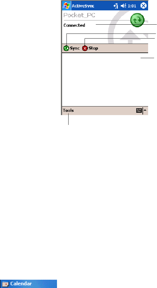
Windows Mobile 2003Chapter —2
42 700 Series Color Mobile Computer User’s Manual
For information about using ActiveSync on your desktop, start ActiveSync
on your desktop, and then see ActiveSync Help.
Tap to synchronize via IR or change synchronization settings.
View connection status.
Tap to connect and synchronize.
Taptostopsynchronization.
View synchronization status.
For more information about ActiveSync on your 700 Color Computer,
switch to ActiveSync, then tap Start >Help.
Microsoft Pocket Outlook
Microsoft Pocket Outlook includes Calendar, Contacts, Tasks, Inbox, and
Notes. Use these programs individually or together, such as, you can use
e-mailaddressesstoredinContactstoaddresse-mailmessagesinInbox.
Using ActiveSync, you can synchronize information in Microsoft Outlook
or Microsoft Exchange on your desktop with your 700 Color Computer.
You can also synchronize this information directly with a Microsoft Ex-
change server. Each time you synchronize, ActiveSync compares the
changes you made on your 700 Color Computer and desktop or server
and updates both computers with the latest information. See ActiveSync
Help on the desktop for information. You can switch to any program by
tapping it on the Start menu.
Calendar: Scheduling Appointments and Meetings
To switch to Calendar on the 700 Color Computer, tap Start >Calendar.
Use Calendar to schedule appointments, including meetings and other
events. You can check your appointments in one of several views (Day,
Week, Month, Year, and Agenda) and set Calendar to remind you of ap-
pointments with a sound or other method. Appointments for the day can
display on the Today screen.
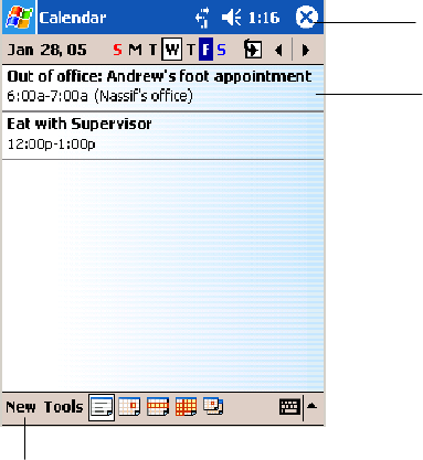
Windows Mobile 2003—Chapter 2
43700 Series Color Mobile Computer User’s Manual
If you use Outlook on your desktop, you can synchronize appointments
between your device and desktop.
Tap to create a new appointment
TaptogotoToday
Tap to display or edit
the appointment details.
Synchronizing Calendar
Calendar items stored on your device can be synchronized with calendar
items on your desktop or Microsoft Exchange Server. (Note that you can
only synchronize information directly with an Exchange Server if your
company is running Microsoft Mobile Information Server 2002 or later.)
Calendar synchronization is automatically selected in ActiveSync.
Calendar items entered on one computer are copied to the other during
synchronization. Handwritten notes and drawings are saved as metafiles
(pictures).
For more information on synchronization, see ActiveSync Help on the
desktop.
Why Use Categories in the Calendar?
Use categories to group related tasks, contacts, and appointments. Then,
use these groupings to display the information you want. For example, you
can easily share your device with another by assigning your appointments
to a category with a special project’s name. You can then use this category
to filter Calendar and only display appointments for that project.

Windows Mobile 2003Chapter —2
44 700 Series Color Mobile Computer User’s Manual
Note: In Month View, the day of an appointment assigned to the Holiday
category appears in red.
TaptoaccesstheMonthview
This day was assigned
the Holiday category.
What’s an All Day Event?
An appointment can either be a normal appointment or an all day event,
which lasts the full day or spans many days. Examples include a trade
show, a vacation, or a seminar. You can also use all day events to schedule
an annual event, such as a birthday or anniversary. In this case, change the
Status box to Free (you may need to scroll to see it) so that it does not
show time as busy in your calendar. All day events do not occupy blocks of
time in Calendar; they appear in banners at the top of the calendar.
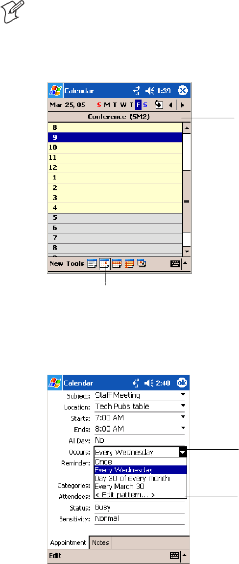
Windows Mobile 2003—Chapter 2
45700 Series Color Mobile Computer User’s Manual
Note: You cannot modify or create all-day events with attendees on the
device. If you create all day events with attendees on your desktop, use Ac-
tiveSync to copy such events to the device. Then, view them in Calendar.
For more information on copying files, see ActiveSync Help.Tousethe
device to schedule an appointment with attendees lasting all day, set type
to “Normal,” then adjust the date and time appropriately.
Tap to access the Day view
This describes the all
day event.
What’s a Recurrence Pattern?
If you have an appointment or task that you do on a regular basis, such as
a weekly team meeting or a monthly status report, enter the item once and
set a recurrence pattern for it. If the default patterns in the list are not
what you need, you can create your own pattern using the wizard.
Select your recurrence
pattern from this drop-
down list.
Select <Edit pattern...>
to access the wizard
with which to custom-
ize your recurrence.
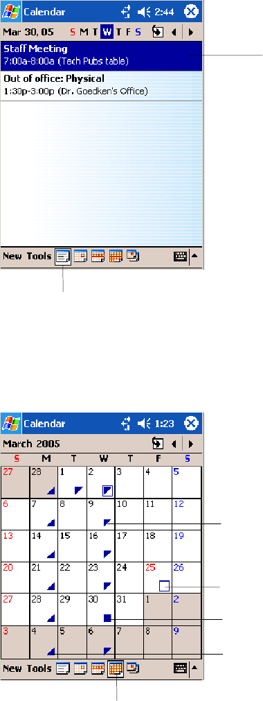
Windows Mobile 2003Chapter —2
46 700 Series Color Mobile Computer User’s Manual
Viewing Appointments
You can view appointments in one of several views (Agenda, Day, Week,
and Month). In Agenda view, upcoming appointments are displayed in
bold. To see detailed appointment information in any view, tap the ap-
pointment. To see a list of available actions for an appointment, tap and
hold the appointment. Tap Start >Today to quickly see your appoint-
ments for the day.
Tap to access the Agenda view
This displays the ap-
pointment in bold.
Month view displays symbols to indicate the types of appointments you
have on a given day. An upward triangle indicates a morning appointment;
a downward triangle indicates an afternoon appointment. If you have ap-
pointments in the morning and afternoon, a solid square is displayed. If
you have an all day event not marked Free, a hollow square is displayed.
TaptoaccesstheMonthview
This displays an all day event
not marked Free.
This displays a morning appointment.
This displays appointments in both
morning and afternoon.
This displays an afternoon appointment.
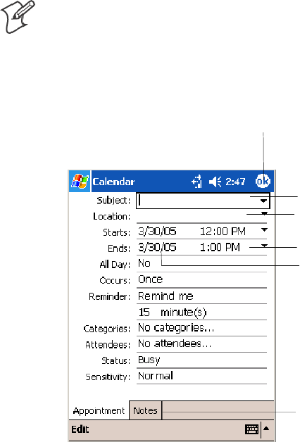
Windows Mobile 2003—Chapter 2
47700 Series Color Mobile Computer User’s Manual
Creating or Changing an Appointment
To create an appointment, tap New. To select a new date from a pop-up
calendar, tap the display date. To enter or select a new time, tap the dis-
play time. Enter the appointment details, and when finished, tap OK to
return to the calendar.
If you are working in Day view, tap the time slot for the new appointment
and then tap New to have the time automatically entered for you.
To change an appointment, tap it in the calendar, then tap Edit.Change
any appointment detail by tapping it and entering the new information.
Note: Tap the arrows to the right of the description and location boxes to
choose from previous entries.
When entering a time, you can type military and abbreviated time forms,
such as 2300 (becomes 11:00 PM), 913pm (becomes 9:13 PM), 911 (be-
comes 9:11 AM), and 9p (becomes 9:00 PM).
Tap to return to the calendar
(the appointment is saved
automatically).
Tap to choose from
predefined text.
Tap to choose from previously
entered locations.
Taptoselectatime.
Tap to select a date.
Notes is a good place for
maps and directions.
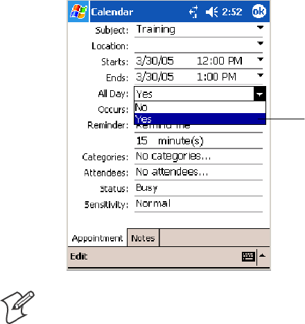
Windows Mobile 2003Chapter —2
48 700 Series Color Mobile Computer User’s Manual
Creating an All Day Event
To create an all day event, tap New,thentapAll Day, then select Yes.
Tap to select either
Yes or No whether
this is an all day
event.
Note: To change an all day event, switch to Day or Agenda view, tap the
event listed at the top of the calendar, and then tap Edit. Change any ap-
pointment detail by tapping it and entering the new information.
You cannot modify or create all day events with attendees. If you create all
day events with attendees on your desktop, use ActiveSync to copy such
events to the 700 Color Computer, then view them in Calendar. For more
information on copying files, see ActiveSync Help.
To use the device to schedule an appointment with attendees lasting all
day, set type to Normal, then adjust date and time accordingly.
Setting a Reminder for an Appointment
Do the following to set a reminder for an appointment in the calendar:
1Tap the appointment, then tap Edit to change the appointment.
2Tap Reminder and select Remind me.
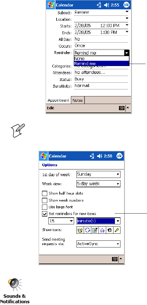
Windows Mobile 2003—Chapter 2
49700 Series Color Mobile Computer User’s Manual
3To change how many minutes before the appointment you are re-
minded, tap the minutes displayed, then select the new minutes from a
drop-down or enter the new minutes. Tap minutes to change hours,
days, or weeks.
TaptoselectRemind me
to enable the reminder
feature.
Note: To automatically set a reminder for all new appointments, in the
calendar, tap Tools >Options, select Set reminders for new items,then
tap the number and timeframe options to change the information given.
Tap this to set reminders
for new appointments
automatically.
To choose how you are reminded, for example by a sound, tap Start >Set-
tings >thePersonal tab>theSounds & Notifications icon.
Adding a Note to an Appointment
You can add written or typed notes and even recordings (if your device
supports recordings) to an appointment. This is a good place for maps,
drawings, and other detailed information.
1In the calendar, tap the appointment, then tap Edit.
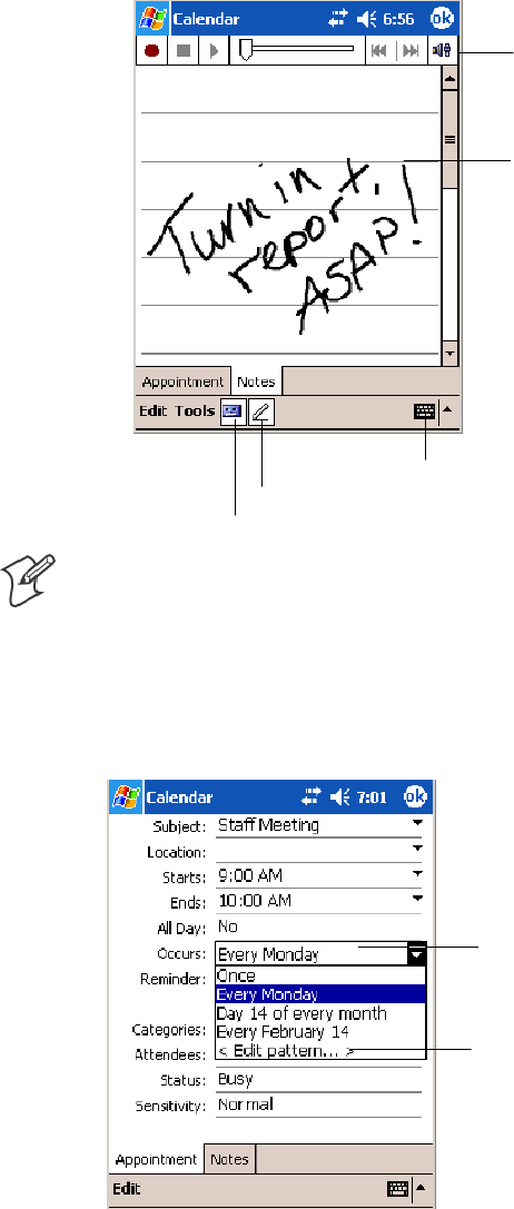
Windows Mobile 2003Chapter —2
50 700 Series Color Mobile Computer User’s Manual
2Tap the Notes tab to enter notes. For specific instructions, tap Start >
Help >Notes to see Notes Help.
Tap to activate the writing pad.
These are controls for
the recorder.
Use your stylus to write
or draw your informa-
tion here.
Tap to activate the recorder.
Tap to activate the keyboard.
Note: To edit an existing note, tap the appointment in the calendar, tap
Edit,thentaptheNotes tab.
Making an Appointment Recurring
To make a recurring appointment, in the calendar, tap the appointment,
then tap Edit.TapOccurs and select a pattern from the list. Or, to create
a new pattern, tap <Edit pattern...>, and follow the steps in the wizard.
Select your recurrence
pattern from this drop-
down list.
Select <Edit pattern...>
to access the wizard
with which to custom-
ize your recurrence.
Assigning an Appointment to a Category
1In the calendar, tap the appointment, then tap Edit.
2Tap Categories.
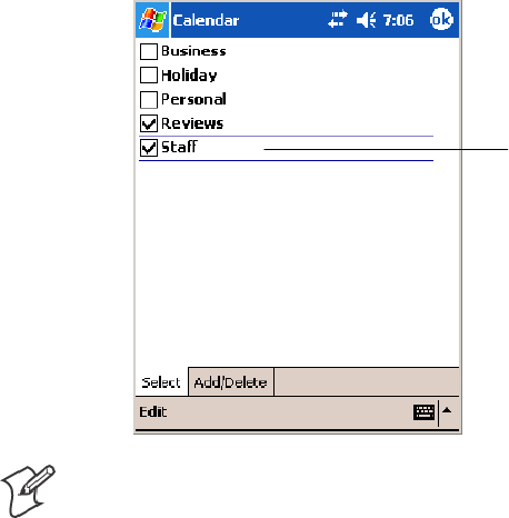
Windows Mobile 2003—Chapter 2
51700 Series Color Mobile Computer User’s Manual
3On the Select tab, select the categories to which you want to assign the
appointment.
4To create a new category, tap the Add/Delete tab, enter the category
name, then tap Add. The new category is automatically selected in the
Select tab.
5Tap ok to return to the appointment.
A check mark indicates
a selected category.
Note: To find an appointment assigned to a category, tap Tools >Catego-
ries and select the type of appointment that you want displayed. To show
all appointments again, tap Tools >Categories and clear all categories.
Sending a Meeting Request
Use Calendar to schedule meetings with people who use Outlook or Pock-
et Outlook. When attendees receive a meeting request, they can accept or
decline the meeting. If they accept, the meeting is automatically added to
their schedule. In addition, their response is sent back to you, and your
calendar is updated.
Before you can send a request, you must enter e-mail addresses in Contacts
Help and set up Inbox to send and receive messages. For more information
on sending and receiving meeting requests, tap Start >Help >Calendar to
see Calendar Help,andtapStart >Help >Inbox to see Inbox Help.
1Tap New, then enter the meeting information.
2Hide the onscreen keyboard, if needed, then tap Attendees.Onlythose
contacts with e-mail addresses are displayed. Select the contacts you
want to invite, then tap ok to return to the appointment.
3Select other desired options and then tap ok.
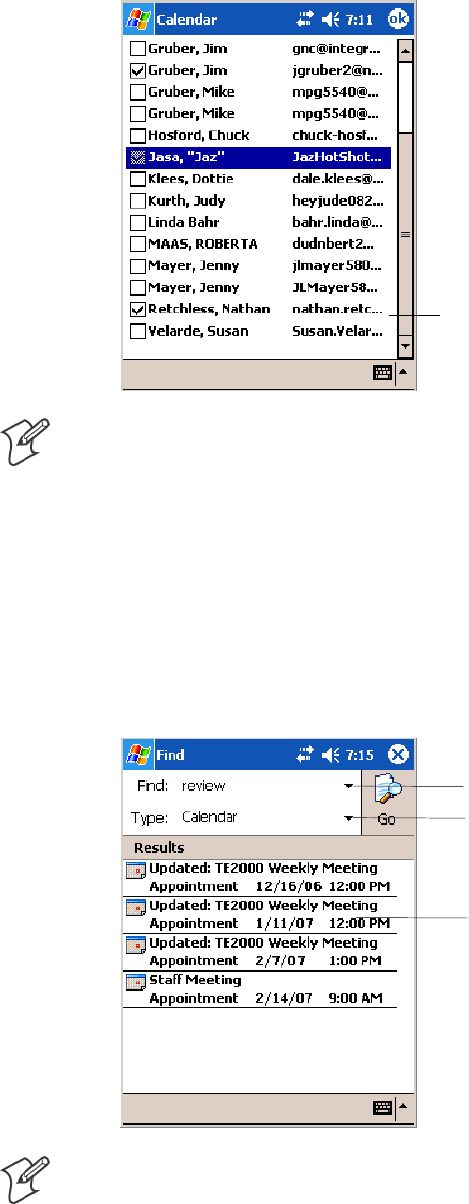
Windows Mobile 2003Chapter —2
52 700 Series Color Mobile Computer User’s Manual
4Inbox automatically creates a meeting request and sends it to the atten-
dees the next time you synchronize with your desktop. Textual notes
entered in the Notes tab (excluding writing or recordings) are sent also.
A check mark indicates
a selected attendee.
Note: If you are sending the meeting request through a connection to an
ISP or the network, rather than through synchronization with your desk-
top, tap Tools >Options.FromtheSend meeting requests via drop-down
list, tap the service to use to send the meeting request.
Finding an Appointment
There are two ways to find an appointment:
STap Start >Find, enter the appointment name, tap the Type arrow and
select Calendar from the drop-down list, and then tap Go.
SIn the calendar, tap Tools >Categories and select the type to display.
To show all appointments, tap Tools >Categories, clear all categories.
Tap this to select from a drop-down
list or enter a phrase.
Tap this for a drop-down list of
areas where to search this phrase.
Tap these to see details.
Note: In Find, you can tap the Find arrow to select from a list of items of
previously searched items or phrases.

Windows Mobile 2003—Chapter 2
53700 Series Color Mobile Computer User’s Manual
Deleting an Appointment
In the calendar, tap and hold the appointment, then tap Delete Appoint-
ment. When you synchronize next, this is also deleted from the desktop.
Changing Calendar Options
In the calendar, tap Tools >Options.
STo see appointment indicators, select icons to display in Show icons.
You can display indicators for recurring appointments, appointments
with notes, appointments with reminders, etc.
SIf you are having trouble reading the calendar, select Use large font.
Tap this to view larger text.
Tap to indicate reminders. Tap to indicate recurrences.
Tap to indicate notes.
Tap to indicate locations.
Tap to indicate attendees.
Tap to indicate private.
Contacts: Tracking Friends and Colleagues
To switch to Contacts on the 700 Color Computer, tap Start >Contacts.
Contacts maintains a list of your friends and colleagues so that you can
easily find the information you are looking for, whether you are at home
or on the road. You can enter both personal and business information.
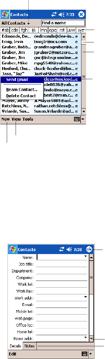
Windows Mobile 2003Chapter —2
54 700 Series Color Mobile Computer User’s Manual
If you use Microsoft Outlook on your desktop, you can synchronize
contacts between your 700 Color Computer and your desktop.
Tap and enter part of a name
to quickly find it in the list.
Tap to create a new contact.
Select the category of contacts you
want displayed in the list.
Tap to see additional phone
numbers and e-mail addresses.
Tap to display or edit the
contact details.
Tap and hold to display a
pop-up menu of actions.
Tap to toggle to By Company (note the Name view)
Creating a Contact
1Tap New, then use the input panel to enter a name and other contact
information. Scroll down to see all available fields.
2To assign the contact to a category, scroll to and tap Categories and se-
lect a category from the list. In the contact list, you can display contacts
by category.
3To add notes, tap the Notes tab. You can enter text, draw, or create a
recording. For more information on creating notes, see “Notes: Captur-
ing Thoughts and Ideas” on page 62.
4When finished, tap OK to return to the contact list.
Tap to return to the contact list (the
contact is saved automatically).
Scroll to see more fields.
Notes is a good place for
maps and directions.
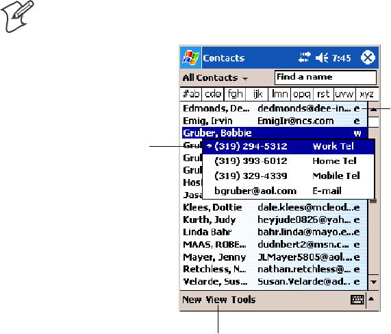
Windows Mobile 2003—Chapter 2
55700 Series Color Mobile Computer User’s Manual
Synchronizing Contacts
Contacts stored on your device can be synchronized with Outlook contacts
stored on your desktop or with Mobile Information Server 2002 or later.
New items entered in one location are copied to the other during synchro-
nization. Handwritten notes and drawings are saved as pictures when syn-
chronizing with a desktop, but removed when synchronizing with a server.
For information on synchronization, see ActiveSync Help on the desktop.
Viewing Contacts
The contact list displays the contact name and the first primary phone
number or e-mail address specified for that contact. Contacts are ordered
by name of contact or company.
STapthedefaultletter(home, work, mobile, or e-mail) to the right of
the contact to see additional phone numbers and e-mail addresses.
SUse your up/down controls on your keypad to select a contact, then
press the left/right controls on your keypad to change the default num-
ber, displayed as a letter to the right of the contact name.
STo see more contact information, tap the contact.
STo see a list of available actions for a contact via a pop-up menu, tap
andholdthecontact.
STo see a list of contacts employed by a specific company, tap View >By
Company. Then, tap the desired company name.
Note: You can change the appearance of the contact list by tapping Tools
>Options.
Tap for a list of phone
numbers and e-mail
addresses.
Tap to toggle By Name and By Company views.
Indicates the
default number.
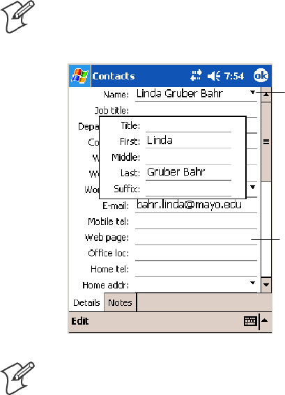
Windows Mobile 2003Chapter —2
56 700 Series Color Mobile Computer User’s Manual
Creating or Changing a Contact
STo create a contact, tap New. To enter notes, tap the Notes tab. When
finished, tap ok to return to the contact list.
STo change a contact, tap it in the contact list, and then tap Edit.To
cancel edits, tap Edit >Undo. When finished making changes, tap ok to
return to the contact list.
Note: Ifyouenteranamewithmorethantwowords,themiddleword
is recorded as a middle name. If your contact has a double first or last
name, tap the Name arrow and enter the names in the proper box.
Tap to access the Name
fields.
Tap anywhere outside the box
to close and return to details.
Note: New contacts are added to the displayed category.
Adding a Note to a Contact
You can add written or typed notes and even recordings (if your device
supports recordings) to a contact. Notes are handy for maps and drawings.
In the contact list, tap the contact, then tap the Notes tab. For specific in-
structions, tap Start >Help >Notes to see Notes Help.
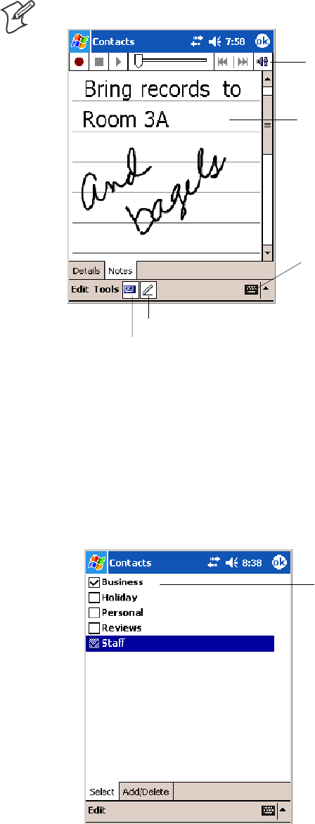
Windows Mobile 2003—Chapter 2
57700 Series Color Mobile Computer User’s Manual
Note: To edit an existing note, tap the contact, tap Edit >theNotes tab.
Tap to activate the writing pad.
These are controls for
the recorder.
Use your stylus to write
or draw your informa-
tion here.
Tap to activate the recorder.
Tap to activate the keyboard.
Assigning a Contact to a Category
1In the contact list, tap the contact, and then tap Edit.
2Scroll to and tap Categories.
3On the Select tab, check the categories to assign to the contact.
4To create a new category, tap the Add/Delete tab, enter the category
name, tap Add. The new category is then checked in the Select tab.
5Tap ok to return to the contacts.
A check mark indicates
a selected category.
Copying a Contact
In the contact list, select the contact. To select multiple contacts, tap and
drag. Tap Tools, and then select Copy Contacts.
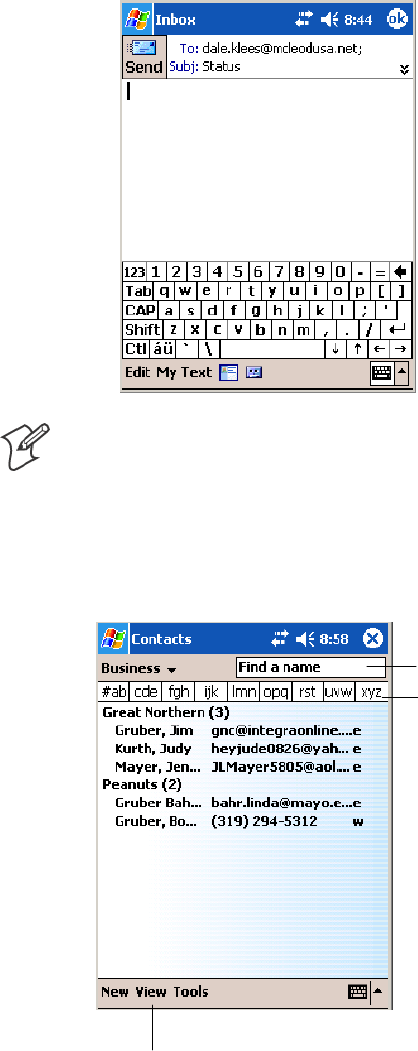
Windows Mobile 2003Chapter —2
58 700 Series Color Mobile Computer User’s Manual
Sending a Message to a Contact
1In the contact list, tap and hold the contact. To select multiple contacts,
tap and drag. Then, tap and hold the selected contacts.
2On the pop-up menu, select Send Email or Send SMS, depending upon
the type of message to send.
Note: To send an e-mail message, you must have an e-mail address config-
ured for the contact. To send an SMS (Short Messaging Service) message,
you must have an SMS number for the contact, which is usually the mo-
bile phone number.
Finding a Contact
There are four ways to find a contact:
Taptojumptothatpor-
tion of the contacts list.
Enter the first few letters of
the contact in question here.
Tap to toggle to By Name (note the Company view)
STap Start >Find, enter the contact name (first, last, or middle), phone
number, or address, select Contacts for the type, then tap Go.

Windows Mobile 2003—Chapter 2
59700 Series Color Mobile Computer User’s Manual
SFrom Contacts, start typing a contact name until you see it displayed on
the screen. To show all contacts again, tap the text box at the top of the
screen and clear the text, or tap the arrow to the right of the text box.
SIn the contact list, tap the category list (labeled All Contacts by default)
and tap the category to which you have assigned a contact. To show all
contacts again, select All Contacts.
STo view the names of companies for which your contacts work, in the
contact list, tap View >By Company. The number of contacts that
work for that company is displayed to the right of the company name.
Note: To quickly move through a long list of contacts, tap one of the sets
of letters displayed at the top of the contact list. This takes you to the con-
tact names beginning with those letters.
Deleting a Contact
1In the contact list, tap and hold the contact. To select multiple contacts,
tap and drag. Then, tap and hold the selected contacts.
2On the pop-up menu, tap Delete Contact. The next time you synchro-
nize, the contact is deleted from the desktop also.
Adding a Contact to Speed Dial
You can create speed dials to call frequently-called numbers with a single
tap. Before you can create a speed dial entry for a phone number, that
number must already exist in Contacts.
1From the Phone keypad, tap Speed Dial >New.
2Tap the desired contact name and number.
3In the Location field, tap the Up/Down arrows to select an available
location to assign as the new speed dial entry. The first speed dial loca-
tion is reserved for your voice mail.
To delete a speed dial entry, go to the Speed Dial list, tap and hold the
contact name in the box to the right of the assigned speed dial number,
then tap Delete.
Changing Contacts Options
In the contact list, tap Tools >Options.
SThe area code and country/region for new contacts are automatically
entered based on the information in Country/Region settings.
SIf you are having trouble reading the contacts in the contact list, select
Use large font.
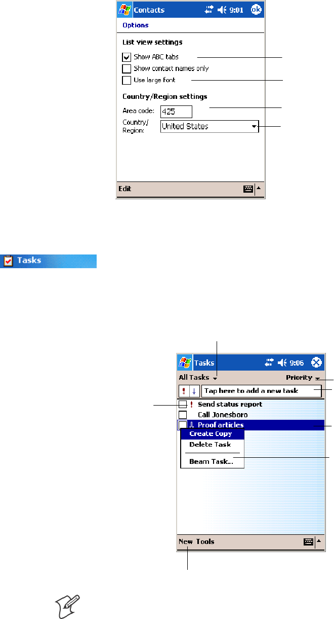
Windows Mobile 2003Chapter —2
60 700 Series Color Mobile Computer User’s Manual
STo increase the available space for displaying contacts in the list, clear
Show ABC tabs.
Enter the three-digit area code.
Select from a drop-down list.
Tap this to view larger text.
Clear this to view more
contacts per screen.
Tasks: Keeping a To Do List
To switch to Tasks on your 700 Color Computer, tap Start >Tasks.
Use Tasks to keep track of what you have to do. A variety of task informa-
tion can display on the Today screen. If you use Microsoft Outlook on
your desktop, you can synchronize tasks between your device and desktop.
Select the sort order
of the list.
Taptocreateanewtask.
Use this entry bar to
assign a task quickly.
Tap to display or edit the
task details.
Tap and hold to display a
pop-up menu of actions.
Select the category of tasks you want displayed in the list.
Indicates a
high priority.
Note: To change the way information is displayed in the list, tap Tools >
Options.
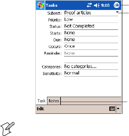
Windows Mobile 2003—Chapter 2
61700 Series Color Mobile Computer User’s Manual
Creating a Task
STo quickly create a task, enter text in the Tap here to add a new task
boxatthetopofthescreen.Ifyoudonotseethisbox,tapTools >
Entry Bar.
STo create a task with detailed information, such as start and due dates,
tap New. To enter notes, tap the Notes tab.
You can enter a start date and due date or enter other information by
first tapping the field. If the input panel is open, you need to hide it to
see all available fields.
Youcanentertext,draw,orcreatearecording.Formoreinformation
on creating notes, see “Notes: Capturing Thoughts and Ideas” on page
62.
STo change a task, tap it in the task list, and then tap Edit.
SUsing the onscreen keyboard, enter a description.
STo assign the task to a category, tap Categories and select a category
from the list. In the task list, you can display tasks by category.
SWhen finished, tap ok to return to the task list.
Taptoreturntothetasklist(the
task is saved automatically).
Tap to choose from predefined
subjects.
Notes is a good place for
maps and drawings.
Note: To quickly create a task with only a subject, tap Entry Bar on the
Tools menu. Then, tap Tap here to add a new task and enter your task
information.
Synchronizing Tasks
Tasks stored on your 700 Color Computer can synchronize with Micro-
soft Outlook on your desktop. Task synchronization is automatically se-
lected in ActiveSync.
New items entered on one computer are copied to the other during syn-
chronization. Handwritten notes and drawings are saved as metafiles (pic-
tures). For more information on synchronization, see ActiveSync Help on
the desktop.
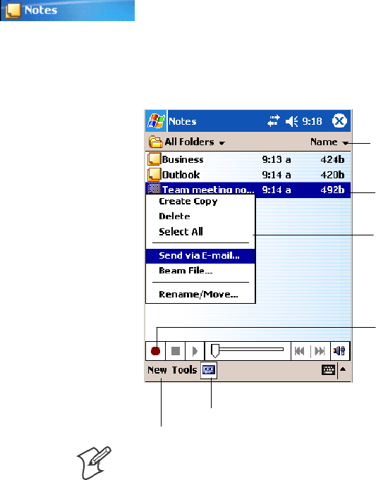
Windows Mobile 2003Chapter —2
62 700 Series Color Mobile Computer User’s Manual
Notes: Capturing Thoughts and Ideas
To switch to Notes on your 700 Color Computer, tap Start >Notes.
Notes helps you quickly capture your ideas, notes, and thoughts. You can
create a note using written and typed text, drawings, and recordings. You
can also share your notes with others through e-mail, infrared, and syn-
chronization with your desktop.
Tap to change the sort
order of the list.
Tap to create a new item.
Taptoopenanoteor
play a recording.
Tap and hold to display a
pop-up menu of actions.
Tap to record.
Tap to show or hide the Recording toolbar.
Note: To create documents with advanced formatting or templates, such
as bulleted lists and tabs, use word processing software developed for your
device, such as Pocket Word.
Creating a Note
To create your note, tap New, then write, draw, type, or record your in-
formation. For information about using the input panel, writing and dra-
wing, and creating recordings, see “Basic Skills” on page 26.
SWriting
Using the stylus, write directly on the screen.
SDrawing
Using the stylus, draw directly on the screen.
STyping
Using the input panel, enter typed text into the 700 Color Computer.
Do this by tapping keys on the onscreen keyboard or by using hand-
writing recognition software.
SRecording
Create a stand-alone recording or embed a recording into a note.

Windows Mobile 2003—Chapter 2
63700 Series Color Mobile Computer User’s Manual
Synchronizing Notes
Notes can be synchronized between your desktop and device either
through notes synchronization or file synchronization. Notes synchroniza-
tion synchronizes the notes on your 700 Color Computer with Outlook
Notes on your desktop. File synchronization synchronizes all notes on
your 700 Color Computer with the My Documents folder for the 700
Color Computer on your desktop.
To synchronize your notes through notes synchronization, first select the
Notes information type for synchronization in ActiveSync. The next time
you synchronize, all notes in My Documents and its subfolder on your
device appear in Outlook Notes on your desktop. Notes that contain only
text appear as regular notes in Outlook on your desktop, while notes con-
taining written text or drawings appear in the device format. In addition,
all notes in the Notes group in Outlook on the desktop appear in Notes on
the device.
To synchronize your notes as files, in ActiveSync, select the Files informa-
tion type for synchronization and clear the Notes information type. When
you select Files, the My Documents folder for the 700 Color Computer is
created on your desktop. All .PWI files placed in the My Documents fold-
er on your device and all .DOC files placed in the My Documents folder
forthe700ColorComputeronyourdesktoparesynchronized.Password-
protected files cannot be synchronized.
ActiveSync converts documents during synchronization. For information
on synchronization or file conversion, see ActiveSync Help on the desktop.
Note: Whenyoudeleteorchangeanitemoneitheryourdesktopor700
Color Computer, the item is changed or deleted in the other location the
next time you synchronize.
Note: If you synchronize your notes using file synchronization and then
later decide to use notes synchronization, all of your notes are synchro-
nized with Outlook on your desktop and no longer store in the My Docu-
ments folder for the 700 Color Computer.
Inbox: Sending and Receiving E-mail Messages
To switch to Inbox on your 700 Color Computer, tap Start >Inbox.
You can receive Internet e-mail messages and SMS messages in Inbox. In-
ternet e-mail messages are sent by using an address you receive from your
Internet service provider (ISP) or your employer. SMS messages are sent
and received through your wireless phone service provider by using a
phone number as the message address.
You can send and receive e-mail by synchronizing with your desktop, or
by connecting to a Post Office Protocol 3 (POP3) or Internet Message Ac-
cess Protocol 4 (IMAP4) mail server. You need to set up an e-mail account
for each method that you use except for Microsoft ActiveSync, which is set
up by default. The ActiveSync folder on your 700 Color Computer stores
messages that you send and receive through synchronization with a desk-
top. Account names appear as folders in the folder list (located on the left,
under the navigation bar) in the Inbox message list.
Windows Mobile 2003Chapter —2
64 700 Series Color Mobile Computer User’s Manual
With synchronization, messages are synchronized between the device In-
box and the PC Inbox by using ActiveSync and Microsoft Exchange or
Microsoft Outlook. For more information, see “Synchronizing E-mail
Messages” below.
When connecting to a POP3 or IMAP4 server, you use a modem to con-
nect to your Internet service provider (ISP), or a modem or Ethernet card
to connect to the local area network to which your e-mail server is connec-
ted. You can also use your phone to connect by using a cellular line con-
nection. For information, see “Connecting to a Mail Server” on page 65.
Synchronizing E-mail Messages
After selecting Inbox for synchronization in ActiveSync, e-mail messages
are synchronized as part of the general synchronization process. During
synchronization:
SMessages are copied from the Inbox folder on your desktop or the
Microsoft Exchange server to the Inbox folder on your 700 Color Com-
puter. (Note that you can only synchronize information directly with an
Exchange Server if your company is running Microsoft Mobile Infor-
mation Server 2002 or later.) By default, you receive messages from the
last three days only, the first 100 lines of each new message, and file at-
tachments of less than 100 KB in size.
SMessages in the Outbox folder on your device are transferred to Ex-
change or Outlook and then sent from those programs.
SThe messages on the two computers are linked. When you delete a mes-
sage on your 700 Color Computer, it is deleted from your desktop the
next time you synchronize.
SMessages in subfolders in other e-mail folders in Outlook are synchro-
nized only if they were selected for synchronization in ActiveSync.
For information on initiating Inbox synchronization or changing synchro-
nization settings, see ActiveSync Help on your desktop or select Start >
Help >Connections to see Connections Help.
Managing E-mail Messages and Folders
Each e-mail account and SMS account has its own folder hierarchy with
five default folders: Inbox, Outbox, Deleted Items, Drafts, and Sent Items.
The messages you receive and send through the mail account are stored in
these folders. You can also create additional folders within each hierarchy.
The Deleted Items folder contains messages that were deleted on the de-
vice. The behavior of the Deleted Items and Sent Items folders depends on
the Inbox options you have chosen.
The behavior of the folders you create depends on whether you are using
ActiveSync, SMS, POP3, or IMAP4.
SIf you use ActiveSync,
e-mail messages in the Inbox folder in Outlook automatically synchro-
nize with your device. You can select to synchronize additional folders
by designating them for ActiveSync. The folders you create and the
messages you move are then mirrored on the server. For example, if you
Windows Mobile 2003—Chapter 2
65700 Series Color Mobile Computer User’s Manual
move two messages from the Inbox folder to a folder named Family,
and you have designated Family for synchronization, the server creates a
copy of the Family folder and copies the messages into that folder. You
can then read the messages while away from your desktop.
SIf you use SMS,
messages are stored in the Inbox folder.
SIf you use POP3
and you move e-mail messages to a folder you created, the link is broken
between the messages on the device and their copies on the mail server.
The next time you connect, the mail server sees that the messages are
missing from the device Inbox and deletes them from the server. This
prevents you from having duplicate copies of a message, but it also
means that you no longer have access to messages that you move to fold-
ers created from anywhere except the 700 Color Computer.
SIf you use IMAP4,
the folders you create and the e-mail messages you move are mirrored
on the server. Therefore, messages are available to you anytime you con-
nect to your mail server, whether it is from your 700 Color Computer
or desktop. This synchronization of folders occurs whenever you con-
nect to your mail server, create new folders, or rename or delete folders
when connected.
For all accounts except ActiveSync, you can access folder options by tap-
ping Tools >Manage Folders.
Connecting to a Mail Server
In addition to synchronizing e-mail messages with your desktop, you can
send and receive e-mail messages by connecting to an e-mail server using a
modem or network card connected to your 700 Color Computer. You
need to set up a remote connection to a network or an ISP, and a connec-
tion to your e-mail server.
When you connect to the e-mail server, new messages are downloaded to
the 700 Color Computer Inbox folder, messages in the 700 Color Com-
puter Outbox folder are sent, and messages that were deleted on the e-mail
server are removed from the 700 Color Computer Inbox folder.
Messages that you receive directly from an e-mail server are linked to your
e-mail server rather than your desktop. When you delete a message on
your 700 Color Computer, it is also deleted from the e-mail server the
next time you connect based on the settings selected in ActiveSync.
You can work online or offline. When working online, you read and re-
spond to messages while connected to the e-mail server. Messages are sent
as soon as you tap Send, which saves space on your 700 Color Computer.
When working offline, once you have downloaded new message headers or
partial messages, you can disconnect from the e-mail server and then de-
cide which messages to download completely. The next time you connect,
Inbox downloads the complete messages you have marked for retrieval and
sends the messages you have composed.

Windows Mobile 2003Chapter —2
66 700 Series Color Mobile Computer User’s Manual
Setting Up or Changing an Account
STo set up a POP3 or IMAP4 e-mail account, tap Accounts >New Ac-
count. Follow the instructions in the New Account Wizard.
STo set up an SMS account, tap Accounts >Accounts, and then tap
SMS. Follow the instructions on the screen.
To change options for an account,tapAccounts >Accounts,thentapthe
name of the account, and follow the instructions on the screen.
To delete an account,tapAccounts >Accounts, then tap and hold the name
of the account, and then tap Delete.
Note: You can set up several e-mail accounts including your ActiveSync
account, but you can set up only one SMS account.
Note: You cannot add a new account while connected. Tap Accounts >
Disconnect to disconnect.
Note: You cannot delete your SMS account.
Downloading Messages from the Server
In Inbox, tap Accounts >Connect to open a connection to the Internet or
your corporate network, depending on the account. For more information,
tap Start >Help >Connections to see Connections Help.
1Tap Accounts and ensure that the account you want to use is selected
(marked by a bullet.)
2Tap Connect. The messages on your 700 Color Computer and e-mail
server are synchronized: new messages are downloaded to the 700 Color
Inboxfolder,messagesinthe700ColorOutboxfolderaresent,and
messages that were deleted from the server are removed from the 700
Color Inbox. Tap a message in the message list to open it.
3If you read a message and decide that you need the full copy, tap Edit >
Mark for Download while in the message window. If you are in the
message list, tap and hold the message, and then tap Mark for Down-
load. This also downloads message attachments if you selected those op-
tions when you set up the e-mail account. You can also choose to down-
load full copies of messages by default.
4When finished, tap Accounts >Disconnect.
Note: Receiving entire messages consumes storage memory.
Note: The size column in the message list displays the local size and server
size of a message. Even when a message has downloaded fully, these num-
bers may differ because the size of a message can vary between the server
and the device.
Composing and Sending Messages
To compose a message:
1In the message list, tap New.
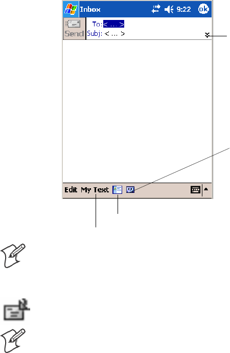
Windows Mobile 2003—Chapter 2
67700 Series Color Mobile Computer User’s Manual
2To select an account, tap the From list and select “ActiveSync,” “SMS,”
or the desired e-mail account.
3Enter the e-mail address or SMS address of one or more recipients, sepa-
rating them with semicolons. To access addresses and phone numbers
from Contacts, tap To.
4Enter your message. To quickly add common messages, tap My Text
and tap a desired message.
5To check spelling, tap Edit >Spell Check.
6Tap Send. If you are working offline, the message is moved to the Out-
box folder and is sent the next time you connect.
Tap to show or hide the
complete header.
Tap to show or hide
the recording tool bar.
Tap to display the Address Book.
Tap to insert common (preset) messages.
Note: If you are sending an SMS message and want to know if it was re-
ceived, before sending the message, tap Edit >Options >Request SMS
text message delivery notification.
You can directly call the sender of an SMS message by tapping the icon
shown to the left, then Call.
Note: Depending on the e-mail address options that you select, you can
use a directory service in addition to your contact list to verify names.
Companion Programs
The companion programs consist of Microsoft Pocket Word, Microsoft
Pocket Excel, Windows Media Player, and Microsoft Reader. To switch to
a companion program on your 700 Color Computer, tap Start >
Programs, then tap the program name.

Windows Mobile 2003Chapter —2
68 700 Series Color Mobile Computer User’s Manual
Pocket Word
Pocket Word works with Microsoft Word on your desktop to access copies
of your documents. You can create new documents on your 700 Color
Computer, or you can copy documents from your desktop to your 700
Color Computer. Synchronize documents between your desktop and your
700 Color Computer to have up-to-date content in both locations.
Creating a Document
Use Pocket Word to create documents, such as letters or meeting minutes.
To create a new file, tap Start >Programs >Pocket Word >New. You get
either a blank document or a template, depending on what you have se-
lected in the Tools >Options dialog box. Select an input mode from the
View menu.
You can open only one document at a time; when you open a second doc-
ument, you have to save the first. You can save a document you create or
edit in formats such as Word (.DOC), Pocket Word (.PSW), Rich Text
Format (.RTF), and Plain Text (.TXT).
Pocket Word contains a list of files stored on your 700 Color Computer.
Tap a file in the list to open it. To delete, make copies of, and send files,
tap and hold a file in the list, then, select the action on the pop-up menu.
Tap to change the sort
order of the list.
Tap to create a new document.
Tap to open a document.
Tap and hold an item to
see a pop-up menu of
actions.
You can enter information in Pocket Word in one of four modes (typing,
writing, recording, and drawing), which are displayed on the View menu.
Each mode has its own toolbar, which you can show and hide by tapping
the Show/Hide Toolbar icon on the command bar.
You can change the zoom magnification by tapping View >Zoom,then
select the percentage you want. Select a higher percentage to enter text and
a lower one to see more of your document.
If you are opening a Word document created on a desktop, you may select
View >Wrap to Window so that you can see the entire document.
To check spelling, select text, then tap Tools >Spell Check.Touseyour
new document as a template, move the document to the Templates folder.

Windows Mobile 2003—Chapter 2
69700 Series Color Mobile Computer User’s Manual
You can insert the data in a document. First, make sure that no drawings
are selected, tap and hold anywhere on the document, then tap Insert
Date from the pop-up menu.
Typing Mode
Using the input panel, enter typed text into the document. For more in-
formation on entering typed text, see “Basic Skills” on page 26.
To format existing text and to edit text, first select the text. You can select
text as you do in a Word document, using your stylus instead of the mouse
to drag through the text you want to select. You can search a document to
find text by tapping Edit >Find/Replace.
Tap to show or hide the toolbar.
Tap to change
format options.
Taptoformattext.
Taptoreturntothe
document list (changes
are saved automatically).
Tap and hold to see a pop-up menu of actions.

Windows Mobile 2003Chapter —2
70 700 Series Color Mobile Computer User’s Manual
Writing Mode
In writing mode, use your stylus to write directly on the screen. Ruled
lines are displayed as a guide, and the zoom magnification is greater than
in typing mode to allow you to write more easily. For more information
on writing and selecting writing, see “Basic Skills” on page 26.
Tap to select formatting options, such as
pen weight and line color.
With Space icon selected,
drag to insert space. An arrow
appears showing the space
direction and size.
Tap to highlight selected text.
Space
icon.
Pen
icon.
Note: If you cross three ruled lines in a single stylus stroke, the writing
becomes a drawing, and can be edited and manipulated as described in
“Drawing Mode” on the next page.
Note: Written words are converted to graphics (metafiles) when a Pocket
Word document is converted to a Word document on your desktop.
Recording Mode
In recording mode, embed a recording into your document. Recordings
are saved as .WAV files. For more information on recording, see “Basic
Skills” on page 26.
For more information on using Pocket Word, tap Start >Help >Pocket
Word to see Pocket Word Help.
Drawing Mode
In drawing mode, use your stylus to draw on the screen. Grid lines appear
as a guide. When you lift your stylus off the screen after the first stroke, a
drawing box indicating the boundaries of the drawing appears. Every sub-
sequent stroke within or touching the drawing box becomes part of the
drawing. For more information on drawing and selecting drawings, see
“Basic Skills” on page 26.
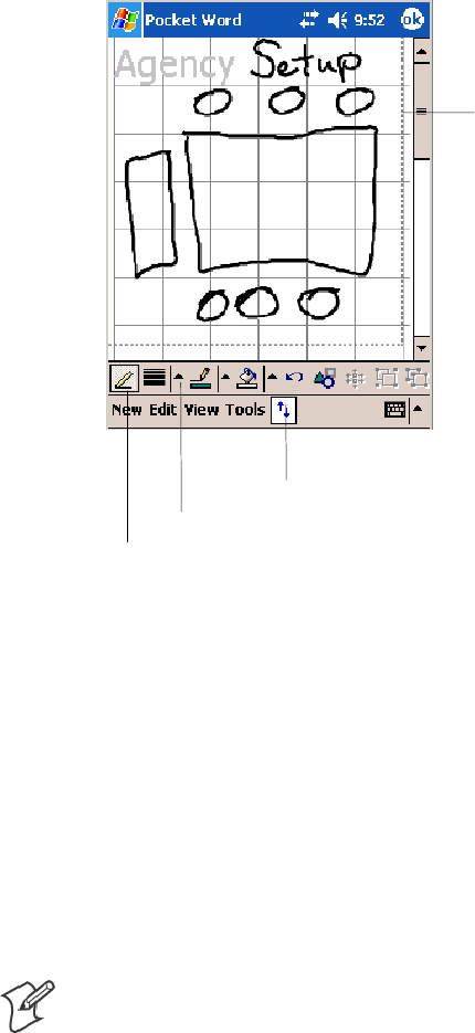
Windows Mobile 2003—Chapter 2
71700 Series Color Mobile Computer User’s Manual
Tap to select formatting options, such as
line weight, fill color, and line color.
Resize an object by dragging
the selection handles.
Tap an arrow to see your choices.
Pen icon.
Synchronizing Pocket Word Documents
Pocket Word documents can be synchronized with Word documents on
your desktop. To synchronize files, first select the Files information type
for synchronization in ActiveSync. When you select Files, the My Docu-
ments folder for the 700 Color Computer is created on your desktop.
Place all files you want to synchronize with the device in this folder. Pass-
word-protected files cannot be synchronized.
All Pocket Word files stored in My Documents and its subfolders are syn-
chronized with the desktop. ActiveSync converts documents during syn-
chronization.
For more information on synchronization or file conversion, see ActiveSync
Help on the desktop.
Note: When you delete a file on either your desktop or your 700 Color
Computer, the file is deleted in the other location when you synchronize.
Pocket Excel
You can create and edit workbooks and templates in Microsoft Pocket Ex-
cel as you do in Microsoft Excel on your desktop. Pocket Excel workbooks
are usually saved as .PXL files, but you can also save them in .XLS format.
When you close a workbook, it is automatically named and placed in the
Pocket Excel workbook list. You can attach a password to a workbook to
help ensure privacy.
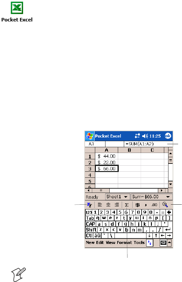
Windows Mobile 2003Chapter —2
72 700 Series Color Mobile Computer User’s Manual
Creating a Workbook
Use Pocket Excel to create workbooks, such as expense reports and mileage
logs. To create a new file, tap Start >Programs >Pocket Excel >New.A
blank workbook appears. Or, if you have selected a template for new
workbooks in the Tools >Options dialog box, that template appears with
appropriate text and formatting already provided. You can open only one
workbook at a time; when you open a second workbook, save the first.
You can save a workbook you create or edit in a variety of formats,
including Pocket Excel (.PXL) and Excel (.XLS). You can also save a
workbook as a template by moving the workbook to the Templates folder.
Pocket Excel contains a list of the files stored on your 700 Color Comput-
er. Tap a file in the list to open it. To delete, make copies of, and send
files, tap and hold a file in the list, then select the action from the menu.
Pocket Excel provides fundamental spreadsheet tools, such as formulas,
functions, sorting, and filtering. To display the toolbar, tap View >
Toolbar.
Zoom icon.
Format icon.
AutoSum icon.
Cell contents appear
here as you enter them.
Note: If your workbook contains sensitive information, you can protect it
with a password. To do so, open the workbook, tap Edit >Password.Ev-
ery time you open the workbook, enter a password, preferably one that is
easy for you to remember but hard for others to guess.
Tips for Working in Pocket Excel
Note the following when working in large worksheets in Pocket Excel:
SView in full-screen mode to see as much of your worksheet as possible.
Tap View >Full Screen. To exit full-screen mode, tap Restore.
STap View >Zoom and select a percentage so that you can easily read
the worksheet.
SShow and hide window elements. Tap View and then tap the elements
youwanttoshoworhide.

Windows Mobile 2003—Chapter 2
73700 Series Color Mobile Computer User’s Manual
SFreeze panes on a worksheet. First select the cell where you want to
freeze panes. Tap View >Freeze Panes. You might want to freeze the
top and leftmost panes in a worksheet to keep row and column labels
visible as you scroll through a sheet. Tap View >Unfreeze Panes to
undo this process.
SSplit panes to view different areas of a large worksheet. Tap View >
Split. Then drag the split bar to where you want it. To remove the split,
tap View >Remove Split.
SShow and hide rows. To hide a row, select a cell in the row you want to
hide. Then tap Format >Row >Hide. To show a hidden row, tap
Tools >Go To, and then type a reference that is in the hidden row.
Then tap Format >Row >Unhide.
SDo the same to show and hide columns. To hide a column, select a cell
in the column you want to hide. Then tap Format >Column >Hide.
To show a hidden column, tap Tools >Go To, type a reference that is
in the hidden column, then tap Format >Column >Unhide.
For more information on using Pocket Excel, tap Start >Help >Pocket
Excel to see Pocket Excel Help.
MSN Messenger
MSN Messenger on your 700 Color Computer provides the same chat
environment as MSN Messenger on your desktop. These features include:
SSeeing who is online
SSending and receiving instant messages
SHaving an instant message conversation with a group of contacts
STelling contacts that you are unavailable
SBlocking contacts from seeing your status or sending you messages
To use MSN Messenger, you need a Microsoft Passport account, or a
Microsoft Exchange e-mail account that your employer provides. Once
you have one of these accounts, do the following:
1Set up a connection on your 700 Color Computer, such as a modem or
wireless connection, that enables you to connect to the Internet.
2SetupanaccountinMSNMessenger.
3Sign in to MSN Messenger.
Note: To set up a free Hotmail account, go to www.hotmail.com.
To set up a Microsoft Passport account, go to www.passport.com.
To set up an Exchange account, see your network administrator.
For more information on using MSN Messenger, tap Start >Help >MSN
Messenger to see MSN Messenger Help.
To switch to MSN Messenger, tap Start >Programs >MSN Messenger.
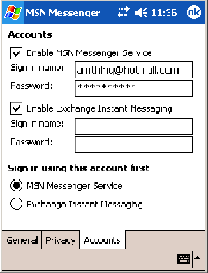
Windows Mobile 2003Chapter —2
74 700 Series Color Mobile Computer User’s Manual
Setting Up an Account
Before you can use MSN Messenger, you must set up the instant messag-
ing accounts to use. For MSN Messenger Service, you must have a Micro-
soft Passport or Hotmail account. For Exchange Instant Messaging, you
must have an Exchange account.
1Create a connection for your device. To use MSN Messenger Service,
set up a connection to the Internet; to use Exchange Instant Messaging,
set up a connection to your corporate network.
2In MSN Messenger, tap Tools >Options >theAccounts tab.
3Select either Enable MSN Messenger Service,orEnable Exchange In-
stant Messaging,orboth.
4Enter your sign-in name and password for the selected accounts. Your
sign-in name is usually in the username@domain.com form.
5If you selected both accounts, under Sign in using this account first,
select which account to sign in to first.
Signing In and Out
STo sign in, tap anywhere on the screen, follow directions on the screen.
STo sign out, tap Tools >Sign Out.
STo sign in upon connecting, tap Tools >Options >General and select
the Run this program upon connection box.
SSigning in to an Exchange account may take several minutes depending
upon your connection speed. Reducing the number of Exchange con-
tacts decreases your sign-in time.
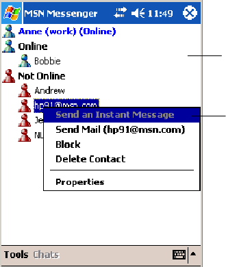
Windows Mobile 2003—Chapter 2
75700 Series Color Mobile Computer User’s Manual
Working with Contacts
The MSN Messenger window shows all of your messenger contacts at a
glance, divided into Online and Not Online categories. From this view,
while connected, you can chat, send e-mail, block the contact from chat-
ting with you, or delete contacts from your list using the pop-up menu.
Tap a contact to start a
chat.
Tap and hold to display a
pop-up menu of actions.
To add a contact, tap Tools >Add a Contact and follow the directions on
the screen. To delete a contact, tap and hold the contact’s name, then tap
Delete Contact from the pop-up menu. To see others online without be-
ing seen, tap Tools >My Status >Appear Offline.
Managing Contacts
For alerts each time you are added to a contact list, tap Tools >Options >
the Privacy tab.
STo block a contact from your status and sending you messages, tap the
contact, then tap the right arrow to move the contact to My Block List.
STo unblock a contact, tap the contact and tap the left arrow. This
moves the contact to My Allow List.
STo receive an alert when someone adds you to their contacts list, select
Alert me when I am added to a Passport contact list.

Windows Mobile 2003Chapter —2
76 700 Series Color Mobile Computer User’s Manual
STo see who has you listed as a contact, tap View.
Sending a Message
STap a contact to whom you want to send a message. Enter your message
in the text entry area at the bottom of the screen and tap Send.To
quickly add common messages, tap My Text and tap a desired message.
STo invite another contact to an ongoing chat, tap Tools >Invite and
tap a contact.
STo see who is already chatting or to switch between chats, tap Chats.
Enter a message.
Tap to send message.
Windows Media Player for Windows Mobile
Use Microsoft Windows Media Player for Windows Mobile to play digital
audio and video files stored on the 700 Series Computer or on a network.
To switch to Windows Media Player on your 700 Color Computer, tap
Start >Windows Media.
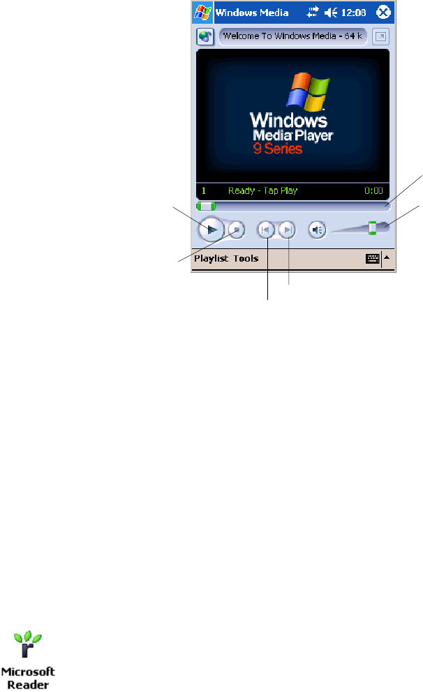
Windows Mobile 2003—Chapter 2
77700 Series Color Mobile Computer User’s Manual
Use Microsoft Windows Media Player on your desktop to copy digital au-
dio and video files to your 700 Color Computer. You can play Windows
Media and MP3 files on your Windows Mobile.
For information about using Windows Media Player for Windows Mobile,
tap Start >Help >Windows Media Player.
Progress of the
current track.
Tap to adjust
volume.
Tap to skip to the next song.
Tap to play a previous song.
Taptostop.
Tap to play or pause.
Microsoft Reader
Use Microsoft Reader to read eBooks on your 700 Color Computer.
Download books to your desktop from your favorite eBook Web site.
Then, use ActiveSync to copy the book files to your activated 700 Color
Computer. The books appear in the Reader Library, where you can tap
them in the list to open them. Each book consists of a cover page, an op-
tional table of contents, and the pages of the book. You can:
SPage through the book by using the Up/Down control on your 700
Color Computer or by tapping the page number on each page.
SAnnotate the book with highlighting, bookmarks, notes, and drawings.
SSearch for text and look up definitions for words.
The Guidebook contains all the information needed to use the software.
To open the Guidebook, tap Help on the Reader command bar. Or, on a
book page, tap and hold on the book title, and then tap Help.
To switch to Microsoft Reader, tap Start >Programs >Microsoft Reader.
Getting Books on Your 700 Color Computer
You can download book files from the Web. Just visit your favorite eBook
retailer and follow the instructions to download the book files. Sample
books and a dictionary are also included in the MSReader folder in the
Extras folder on the Windows Mobile Companion CD. Use ActiveSync to
download the files from your desktop to your activated mobile computer
as described in the Read Me file in the MSReader folder.
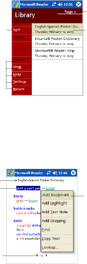
Windows Mobile 2003Chapter —2
78 700 Series Color Mobile Computer User’s Manual
Using the Library
The Library is your Reader home page with a list of the books stored on
your 700 Color Computer or storage card. To open the Library:
SOn the Reader command bar, tap Library.
SOn a book page, tap the book title, then tap Library.
STo open a book, tap its title in the Library list.
Taptoscroll
through the
Library list.
Tap to open
a book.
Tap here to navi-
gate to other parts
of the Reader.
Taptoselecta
sort order.
Reading a Book
Each book consists of a cover page, an optional table of contents, and book
pages. Navigation options are listed in the bottom of the cover page.
The first time you open a book, go to the first page or to the table of con-
tents, if there is one. Subsequently, whenever you open the book, you are
automatically taken to the last page read.
With the text, each book page includes a page number and book title. You
can also page through a book by using the Up/Down/Left/Right controls.
Taptoselecta
navigation option.
Select an option
after dragging to
select a text.
Drag to select text.
Tap arrows to turn
the page, or tap
and hold page
number to bring up
page riffle.

Windows Mobile 2003—Chapter 2
79700 Series Color Mobile Computer User’s Manual
Using Reader Features
Reading a book electronically gives you several options not available with
paper books. These options are available from any book page.
Select text by dragging across the text on the page. Then, tap an option on
the pop-up menu, as described here:
Searching for Text Find text in a book by tapping Find on the pop-up menu. Enter the word you want to
search for, and tap the desired Find option. Reader highlights found text on the page. To
close Find, tap outside the box. To return to your original page, tap the title and then tap
Return on the pop-up menu.
Copying Text You can copy text from books that support this feature into any program that accepts
text. On a book page, select the text you want to copy. Then, tap Copy Text on the pop-
up menu. The text can be pasted into the program of your choice.
Adding Bookmarks When you add a bookmark to a book, a color-coded bookmark icon appears in the right
margin. You can add multiple bookmarks to a book. Then, from anywhere in the book,
tap the bookmark icon to go to the bookmarked page.
Highlighting Text When you highlight text, it appears with a colored background.
Attaching Notes to Text When you attach a note to text, you enter the text in a notepad that appears on top of the
book page. A Note icon displays in the left margin. To show or hide the note, tap the
icon.
Adding Drawings When you add a drawing, a Drawing icon appears in the bottom-left corner of the page,
and drawing tools appear across the bottom of the page. Draw by dragging your stylus.
Annotations Index To see a list of a book’s annotations, including bookmarks, highlights, text notes, and
drawings, tap Annotations Index on the book’s cover page. You can tap an entry in the
list to go to the annotated page.
Removing a Book
When you finish reading a book, you can delete it to conserve space on
your 700 Color Computer. If a copy of the book is stored on your desk-
top, you can download it again at any time.
To remove a book from your 700 Color Computer, tap and hold the title
in the Library list, and then tap Delete on the pop-up menu.
Pocket Internet Explorer
Use Microsoft Pocket Internet Explorer to view Web or WAP pages in
either of these ways:
SDuring synchronization with your desktop, download your favorite
links and mobile favorites that are stored in the Mobile Favorites sub-
folder in Internet Explorer on the desktop.
SConnect to an ISP or network and browse the Web.
When connected to an ISP or network, you can also download files and
programs from the Internet or intranet.
To switch to Pocket Internet Explorer on your 700 Color Computer, tap
Start >Internet Explorer.
Windows Mobile 2003Chapter —2
80 700 Series Color Mobile Computer User’s Manual
Mobile Favorites Folder
Only items stored in the Mobile Favorites subfolder in the Favorites folder
in Internet Explorer on your desktop are synchronized with your 700 Col-
or Computer. This folder was created automatically when you installed
ActiveSync.
Favorite Links
During synchronization, the list of favorite links in the Mobile Favorites
folder on your desktop is synchronized with Pocket Internet Explorer on
your 700 Color Computer. Both computers are updated with changes
made to either list each time you synchronize. Unless you mark the favor-
ite link as a mobile favorite, only the link is downloaded to your 700 Color
Computer. Connect to your ISP or network to view the content.
1In ActiveSync on your desktop, click Tools >Options, and select “Fa-
vorites” from the Mobile Device list. For more information on using
ActiveSync, see ActiveSync Help on the desktop.
2In Internet Explorer on your desktop, save or move favorite links to the
Mobile Favorites subfolder in the Favorites list via Favorites >Organize
Favorites. For more information on using Internet Explorer, see Internet
Explorer Help on the desktop.
3Connect your 700 Color Computer to your desktop. If synchronization
does not start automatically, in ActiveSync on your desktop, click Sync.
Mobile Favorites
If you are using Microsoft Internet Explorer 5.0 or later on your desktop,
you can download mobile favorites to your 700 Color Computer. Syn-
chronizing mobile favorites downloads Web content to your 700 Color
Computer so that you can view pages while you are disconnected from
your ISP and desktop.
Use the Internet Explorer plug-in installed with ActiveSync to create mo-
bile favorites quickly. To create a mobile favorite:
1In ActiveSync on your desktop, click Tools >Options,andselect
“Favorites” from the Mobile Device list. For more information on using
ActiveSync, see ActiveSync Help on the desktop.
2In Internet Explorer 5.0 or greater on your desktop, browse to the page
you want to view offline, then click Tools >Create Mobile Favorite.
3To change the link name, enter a new name in the Name box.
4In the Update box, select a desired update schedule to keep the page in
the Mobile Favorites folder up to date. You can also update content by
clicking Tools >Synchronize in Internet Explorer.
5To save the link in a subfolder of Mobile Favorites, click Create In and
select the desired subfolder.
6Click OK. Internet Explorer downloads the latest version of the page to
your desktop.

Windows Mobile 2003—Chapter 2
81700 Series Color Mobile Computer User’s Manual
7To download the pages that are linked to the mobile favorite you just
created, in Internet Explorer on the desktop, right-click the mobile
favorite, then click Properties.OntheDownload tab, specify the
number of links deep you want to download. To conserve 700 Color
Computer memory, go only one level deep.
8Connect your 700 Color Computer to your desktop. If synchronization
between your 700 Color Computer and desktop does not start, in Acti-
veSync on your desktop, click Sync.
Mobile favorites take up storage memory on your 700 Color Computer.
To minimize the amount of memory used:
SIn the settings for the Favorites information, type in ActiveSync op-
tions, turn off pictures and sounds, or stop some mobile favorites from
being downloaded to the 700 Color Computer. For more information,
see ActiveSync Help.
SLimit the number of downloaded linked pages. In Internet Explorer on
the desktop, right-click the mobile favorite you want to change and then
Properties.IntheDownload tab, specify “0” or “1” for the number of
linked pages you want to download.
Using AvantGo Channels
AvantGo is a free interactive service that gives you access to personalized
content and thousands of popular Web sites. You subscribe to AvantGo
channels directly from your 700 Color Computer. Then, you synchronize
your 700 Color Computer and desktop, or connect to the Internet to
download the content. For more information, visit the AvantGo Web site.
To synchronize an AvantGo channel:
1In Pocket Internet Explorer on your 700 Color Computer, tap to
display your list of favorites.
2Tap the AvantGo Channels link.
3Tap Activate.
4Follow the directions on the screen. Synchronize your 700 Series Com-
puter with your desktop, then tap My Channels to complete the Avant-
Go setup.
5When synchronization is complete, tap the AvantGo Channels link in
your list of favorites to see a few of the most popular channels.
To add or remove channels, tap the Add or Remove link.
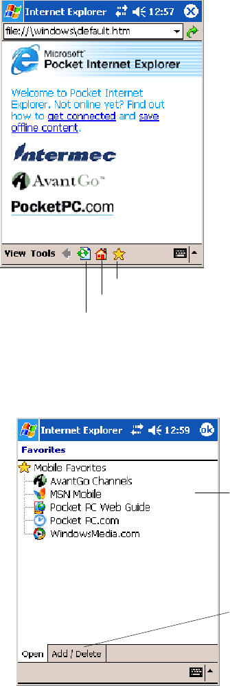
Windows Mobile 2003Chapter —2
82 700 Series Color Mobile Computer User’s Manual
Using Pocket Internet Explorer
You can use Pocket Internet Explorer to browse mobile favorites and chan-
nels that were downloaded to your 700 Color Computer without connect-
ing to the Internet. You can also connect to the Internet through an ISP or
a network connection and browse the Web.
Favorites icon
Home icon
Refresh icon
Viewing Mobile Favorites and Channels
1Tap the Favorites icon to display your list of favorites.
2Tapthepageyouwanttoview.
Tap the favorite you want
to view.
Tap to add or delete a
folder or favorite link.
The page that was downloaded the last time you synchronized with your
desktop opens. If the page is not on your 700 Color Computer, the favor-
ite is dimmed. Synchronize with your desktop again to download the page
to your 700 Color Computer, or connect to the Internet to view the page.

Windows Mobile 2003—Chapter 2
83700 Series Color Mobile Computer User’s Manual
Browsing the Internet
1Set up a connection to your ISP or corporate network.
2To connect and start browsing, do one of the following:
STap the Favorites icon, and then tap the favorite you want to view.
STap View >Address Bar. In the address bar that appears at the top of
the screen, enter the Web address you want to visit and then tap Go.
Tap the arrow to choose from previously entered addresses.
Note: To add a favorite link while using the 700 Color Computer, go to
the page you want to add, tap and hold on the page, and tap Add to
Favorites.
Windows Mobile 2003Chapter —2
84 700 Series Color Mobile Computer User’s Manual

85700 Series Color Mobile Computer User’s Manual
Installing Applications
3
There are multiple ways to get an application to your 700 Series Color
Mobile Computer; just as there are multiple ways to package the applica-
tion for delivery.
Note: “700 Color” pertains to 730, 740, 741, 750, 751, 760, and 761
Computers unless otherwise noted.

Installing ApplicationsChapter —3
86 700 Series Color Mobile Computer User’s Manual
Packaging an Application
Use any of these methods to package an application for installation:
SFor very simple applications, the application itself might be the only file
that needs to be delivered.
SIt could be a directory structure that contains the application, support-
ing files like ActiveX controls, DLLs, images, sound files, and data files.
SOr, you could package an application via a CAB file.
Consider any of the following when choosing a location into which to
store your application:
SIn the basic 700 Color Computer, there are two built-in storage op-
tions: the Object Store and the Persistent Storage Manager (PSM). The
Object Store is RAM that looks like a disk. Anything copied here is de-
leted when a cold-boot is performed on the 700 Color Computer. The
PSM is an area of storage which is embedded in a section of the system’s
FLASH memory. This storage area is not erased during a cold-boot. It
may, however, be erased during the reflashing process. In addition to
storing applications and data files, you do have the option to store a per-
sistent registry to the PSM region.
SIf the optional Secure Digital or CompactFlash storage card is in the
system, then consider this card the primary location for placing an ap-
plications install files. The following folders represent either card:
SThe Secure Digital storage card creates the “\SDMMC Disk” folder.
SThe CompactFlash storage card creates the “\Storage Card” folder.
Note: 730 Computers do not support Compact Flash storage cards.
Instead, the “\Storage Card” folder is created for the Secure Digital
storage card.
SUse the small non-volatile Flash File Store region to hold CAB files that
rebuild the system at cold-boot or install applications from a CAB file
into the Flash File Store so they are “ready-to-run” when a cold-boot is
performed. Since the FLASH in the system has a limited number of
write cycles, do not use the Flash File Store for excessive writing pur-
poses; however, reading is okay.
Files copied to any of these locations are safe when a cold-boot is
performed on a 700 Color Computer — providing the AutoRun system is
installed in the appropriate location Find this system in the 700 Color
Management Tools portion.Copying a CAB file to the “\CabFiles” folder
on one of these cards automatically extracts that CAB file on every
cold-boot to ensure that your system is properly set up (see page 95).
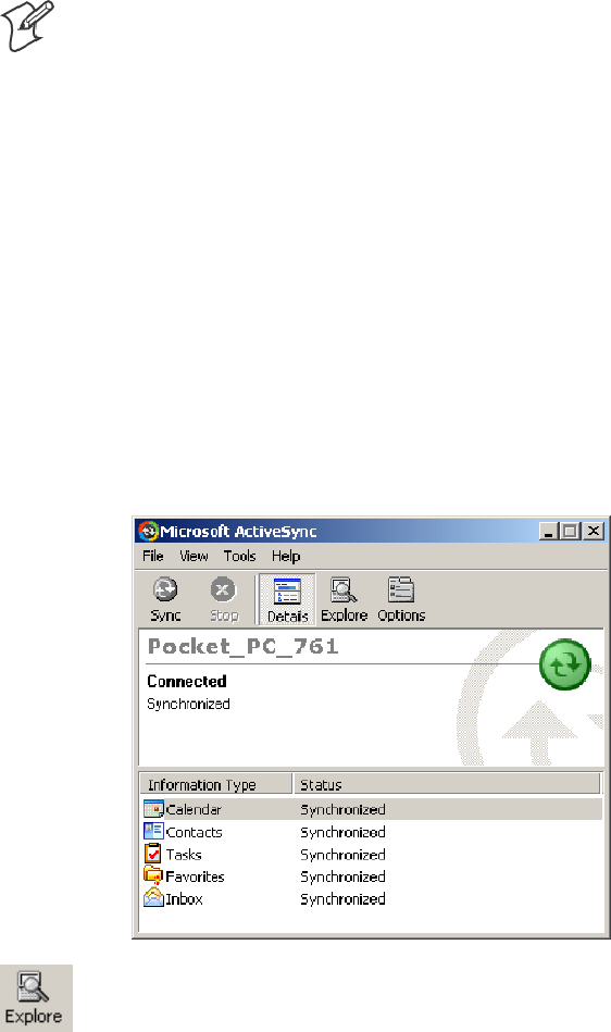
Installing Applications—Chapter 3
87700 Series Color Mobile Computer User’s Manual
Installing Applications
Consider any of these options to get the package to the preferred location:
SMicrosoft ActiveSync (next page)
SStorage cards (page 88)
SFTP Server (page 88)
SRegistry (page 88)
Using Microsoft ActiveSync
Note: These instructions assume the 700 Color Management Tools were
installed on your desktop.
The Microsoft ActiveSync tool is located on the 700 Color Companion CD.
See Chapter 2, “Windows Mobile 2003,” for information about this tool
as provided by Microsoft Corporation.
This can be a serial or USB ActiveSync connection. Files can be copied
using File Explorer on a desktop or a laptop computer. This is usually
good when updating few 700 Color Computers.
These instructions assume that Microsoft ActiveSync was installed onto
your desktop and is up and running. If not, go to Chapter 2, “Windows
Mobile 2003,” for an URL from which to download the latest application.
1Connect your 700 Color Computer to your desktop computer via an
ActiveSync cable.
2Wait for a “Connected” message to appear in the Microsoft ActiveSync
application to signal a connection to the 700 Series Computer. If neces-
sary, select File >Get Connected to initiate a connection.
3Click Explore toaccesstheMobileDevicefolderonyourunit.
4From your desktop, select Start >Windows Explorer, then browse the
“C:\Intermec\700C Mgmt Tools\CabFiles” path for any CAB files
needed for your 700 Color Computer. Select the appropriate file, right-
click the file for a pop-up menu, then select Copy.

Installing ApplicationsChapter —3
88 700 Series Color Mobile Computer User’s Manual
5Within the Mobile Device directory, go to the directory where you
want the files located on the 700 Color Computer, do a right-click for a
pop-up menu, then select Paste.
6When all of the files are pasted, perform a warm-boot on the 700 Color
Computer. When the computer reboots, wait for the LED on the top
left of your keypad to stop blinking. Tap Start >Programs >File
Explorer to locate the newly copied executable files, then tap these files
to activate their utilities.
Using the FTP Server
The 700 Color Computer has a built-in FTP Server that connects to a net-
work via Ethernet, 802.11b, or WAN (Wireless Access Network). This
allows connections to the 700 Color Computer to perform file transfers or
computer management functions. Another benefit is you can create FTP
scripts to automate the process of copying files to the 700 Color Comput-
er. This option is good for when a large number of 700 Color Computers
need updating. See Chapter 7, “Programming,” for more information.
Using a Storage Card
Note: The 730 Computer does not use the CompactFlash storage card,
only Secure Digital storage cards. Use these instructions only if you are
using either a 740 or a 741 Computer that does not have an 802.11 radio
installed. 730, 750, 751, 760, 761 Computers only use Secure Digital
storage cards.
Use the following steps to install an application using either a Compact-
Flash or a Secure Digital storage card:
1Suspend the 700 Color Computer and remove the storage card.
2Insert the storage card into the storage card reader connected to your
desktop PC.
3Create a “\CabFiles” directory on the storage card, then copy (build into
cabfiles) your application, data files, and all required DLLs and drivers
into this directory.
4See “Creating CAB Files” on page 188 to build a “\2577” directory to
control the autolaunching of these CAB files.
5Remove the storage card from your card reader and reinstall it into the
700 Color Computer.
6Warm-boot the 700 Color Computer to install these files.
Replicating 700 Color Settings Using the Registry
This information updates the registry on your 700 Color Computer, con-
firms the registry update, then copies the information onto other 700 Col-
or Computers in your network. If using DHCP, no changes are necessary.
If you are using Static IP, the new 700 Color Computer will have the IP
address of the original 700 Color Computer because the copied registry
includes this information.

Installing Applications—Chapter 3
89700 Series Color Mobile Computer User’s Manual
When you change the IP address using the Intermec Settings applet, the
information is lost when you perform a warm-boot, and the original IP
address is used.
You must load the REGFLUSH.CAB file before running the Registry Save
application. Once you do, perform a warm-boot to keep the IP address.
To install the Registry Save application after a cold-boot is performed,
change the properties of the REGFLUSH.CAB file to that of read-only.
Using ActiveSync, copy the CAB file to the “Flash File Store\Persistent
Copy\CabFiles” folder on the 700 Color Computer, then perform a cold-
boot to load this CAB file.
Deleting the Old Registry File
1On the original 700 Color Computer, select Start >Programs >theFile
Explorer icon, then tap My Device >Flash File Store. Scroll down to
the bottom of the list of files and folders, press and hold your stylus in
the white area beneath for a pop-up menu, then select View All Files.
2Look for a “registry” file. If one exists, select to highlight that file, press
and hold for a pop-up menu, select Delete,thenYes to remove this file.
Downloading the RegFlush CAB File
1Using your web browser, go to the Intermec web site at
www.intermec.com/developersupport. Note that this is subject to change.
2Select Pen Notepads >700 Color Series >Downloads >Tools.
3Scroll down for the “Registry Save Utility (regflush.CAB)” header.
4Click Download next to this header to download the CAB file to a loca-
tion on your desktop.
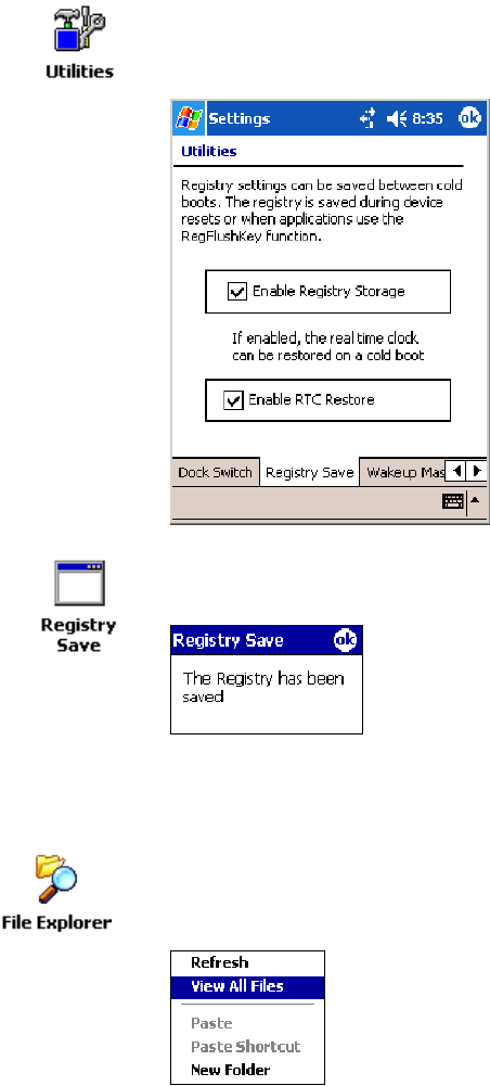
Installing ApplicationsChapter —3
90 700 Series Color Mobile Computer User’s Manual
Loading the Registry Save Application
1On the 700 Color Computer, double-click the REGFLUSH.CAB file
to load the “Registry Save” application.
2Set up the 700 Color Computer to your specifications using the Inter-
mec Settings and other applets.
3Select Start >Settings >theSystem tab>theUtilities icon > the Regis-
try Save tab, then check both Enable Registry Storage and Enable RTC
Restore .Tapok to close, then close Settings.
4Select Start >Programs >theRegistry Save icon to run the Registry
Save application, then tap ok when told the registry was saved.
Confirming the New Registry File
To confirm whether the new registry file exists, do the following:
1On the 700 Color Computer, select Start >Programs >theFile Explor-
er icon, then tap My Device >Flash File Store.Pressandholdyoursty-
lus in the white area for a pop-up menu, then select View All Files.

Installing Applications—Chapter 3
91700 Series Color Mobile Computer User’s Manual
2The new registry file should be on the root of the Flash File Store folder
with today’s date.
Updating Other Computers in Your Network
These instructions assume you have Windows XP on your desktop.
1Connect your 700 Color Computer to your desktop using Microsoft
ActiveSync and a cradle. Make sure the ActiveSync application on your
desktop is up and running and connected to your 700 Color Computer.
2On your desktop, select Start >Settings >Control Panel, double-click
the Folder Options icon, then click the View tab. Beneath “Hidden
files and folders,” check Show hidden files and folders,thenclickOK.
3Using the Microsoft ActiveSync application on your desktop, click Ex-
plore to access the Flash File Store folder on your 700 Color Computer
and locate the “registry” file. Copy this file, then paste it in a temporary
location on your desktop.
4Remove the 700 Color Computer from the cradle, and put another 700
Color Computer in its place. The ActiveSync application on your desk-
top should connect to the new unit.
5Follow the instructions for “Deleting the Old Registry File” starting on
page 89, put the new registry file in the root of the Flash File Store
folder on the new 700 Color Computer, enable the registry save flag via
the Utilities applet, perform a warm-boot. and make sure these settings
are saved.
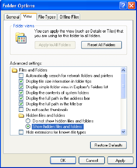
Installing ApplicationsChapter —3
92 700 Series Color Mobile Computer User’s Manual
Updating the System Software
When you upgrade your 700 Color Computer, you are updating the oper-
ating system (OS) and the Persistent Storage Manager (PSM) files.
The PSM files are stored in the Flash File Store region, and deliver Inter-
mec value-added functionality such as data collection, unit configuration
and diagnostics, the Intermec wireless security suite, and the SmartSys-
temstFoundation.
You need to download the latest upgrade files from the Intermec web site
to your desktop PC.
1Start your web browser and go to the Intermec web site at www.inter-
mec.com/wm2003.
2Click the PPC 2003 OS link, fill out the appropriate information, then
click Submit Information.ClickOK to continue.
3Click the link and download the .zip file to your PC.
4Follow the steps in one of the next sections:
SIf you are using a storage card to upgrade the 700 Color Computer,
see next page.
SIf using the SmartSystems Console to upgrade the 700 Color Com-
puter, see “Using the SmartSystems Console to Upgrade the 700 Col-
or Computer“ on page 94.

Installing Applications—Chapter 3
93700 Series Color Mobile Computer User’s Manual
Using a Storage Card to Upgrade the 700 Color Computer
To use a Secure Digital card to upgrade the 700 Color Computer, you
need a Secure Digital card reader and a Secure Digital card formatted as
FAT.
Note: The 700 Color Computer currently supports Delkin Secure Digital
cards only. Intermec cannot guarantee that other Secure Digital cards will
work with the 700 Color Computer.
1Locate the storage card access door at the top of the 700 Color Comput-
er, remove its two screws, remove the door, then remove the storage
card. See the 700 Color with Windows Mobile 2003 Quick Start Guide
(P/N: 962-054-069) for more information.
Storage Media
Access Door
700 Color Computer 730 Computer
This illustration shows the top of the 700 Color Computer on the left and of the 730 Computer
on the right. Note that the keypad is to the bottom.
2Place the storage card in your desktop PC card reader, then copy all re-
quired upgrade files to the storage card.
3Remove the storage card from your card reader, reinstall it into the 700
Color Computer.
4Press the Reset button inside the battery compartment to perform a
cold-boot. Do not use force or a sharp object when pressing the Reset
button, or you may damage the Reset button.
Reset button
This illustration shows the back of the 700 Color Computer on the left and of the 730 Computer
on the right.
5Return the 700 Color Computer to DC power, such as installing it into
a dock connected to external power.
6When the Bootloader Menu shows “complete,“ remove the storage card,
then press the Reset button again to load the new operating system.
Note: The upgrade will fail if the 700 Color Computer is not connected
to external power. For help, see “Accessories” on page 21.

Installing ApplicationsChapter —3
94 700 Series Color Mobile Computer User’s Manual
7When the 700 Color Computer finishes booting, insert the AB10 bat-
tery, then close the battery door.
You may use the 700 Color Computer. You have reset the 700 Color
Computer to its default configuration. You need to set the date and time
and to set its network communications parameters to reestablish commu-
nications with the other devices in the wireless network.
Using the SmartSystems Console to Upgrade the 700 Color Computer
You can use the SmartSystems Console to upgrade the operating system on
your 700 Color Computer. The console is part of SmartSystems Founda-
tion and is available from the Intermec web site via the Intermec Develop-
er Library (IDL). Before you can upgrade your computer, you need:
Sthe SmartSystems Foundation. To download SmartSystems Foundation,
go to www.intermec.com/idl and open the Device Management page.
Sthe device upgrade .exe file. This file is available from the Intermec web
site at www.intermec.com. Go to Service & Support >Downloads.
Make sure the file you select is for your language.
1Install SmartSystems Foundation on your PC and open the console.
2Make sure the console and 700 Color Computers are on the same sub-
net.
3Make sure your 700 Color Computers are either in a communications
dock or charging dock, such as the AD14 dock charger, or that power
management is disabled.
4Download the device upgrade .exe file to your desktop PC.
5Double-click the .exe file on your desktop PC. An InstallShield applica-
tion starts and walks you through the process of extracting the upgrade
files in the default location.
Note: Do not change the default location where InstallShield extracts
the files. The SmartSystems Console requires that the files be in this
location.
6From the SmartSystems Console, locate the device upgrade to install.
7Drag-and-drop the device upgrade onto each 700 Color Computer you
want to upgrade. The SmartSystems Console will tell you that it is
installing the upgrade on your 700 Color Computer.
Once the upgrade is done downloading to your 700 Color Computer,
your 700 Color Computer replaces the operating system and then auto-
matically performs a cold-boot. Progress messages do appear on the 700
Color screen.
The SmartSystems Console will show your 700 Color Computer as offline
(note the red stop sign) until the 700 Color Computer reboots and recon-
nects to the system.
Installing Applications—Chapter 3
95700 Series Color Mobile Computer User’s Manual
Migrating from a 700 Monochrome Computer
As you migrate from a 700 Monochrome Computer to a 700 Color Com-
puter, you need to consider the following: When converting a 700 Mono-
chrome Computer application to run on the 700 Color Computer, most
APIs should work without changes. Below are a few exceptions:
SThe 700 Monochrome Computer uses the “\Storage Card” folder for
nonvolatile storage. You may need to change the application to store
data onto the “SDMMC Disk” folder instead of the “\Storage Card”
folder if a Secure Digital storage card is present in the system.
SIf the application uses the RegFlushKey() API, it must first verify that
the proper media is available in the system and call this API.
SIf the application is using the 700 Color switchable dock, use the
IOCTL_DOCK_SWITCH value from the
IOCTL_HAL_ITC_WRITE_SYSPARM function to set the proper
port on the dock before communications. See more information about
this KernelIOControl function in Chapter 7, “Programming.”
SSome WAN radio options have changed. Review the WAN radio infor-
mation in Chapter 4, “Network Support,“to determine if any changes
are required in your application.
SArrow and tab keys are reversed from the 700 Monochrome Computer.
Keyboard remapping is available on the 700 Color Computer should
you need to map these keys like that of the 700 Monochrome Comput-
er (see page 92).
STargeting the ARM (SA1110) processor which creates applications that
run on the 700 Color Computer requires the Windows Mobile 2003
SDK.
Installing Cabinet Files
CAB files (short form of “cabinet” files) are compressed folders as defined by
Microsoft. A “cabinet” file is a single file, usually suffixed with .CAB, that
stores compressed files in a file library. A compressed file can be spread
over several cabinet files. During installation, the setup application decom-
presses the files stored in a cabinet and copies them to the user’s system.
For the 700 Series Computer, CAB files register DLLs, create shortcuts,
modify registry entries, and run custom setup programs. Tap a CAB file to
extract that file or place the CAB file on one of the approved storage de-
vices in the “\CabFiles” folder, then perform a warm-boot on the 700 Se-
ries Computer. There are two methods available to extract a CAB file:
STap a CAB file to extract it. With this method, the CAB file is automat-
ically deleted when the extraction process is successful, unless the CAB
file is set with the read-only attribute.
SUse AUTOCAB to extract all files when a cold-boot is performed on
the 700 Series Computer. See the Software Tools User’s Manual for in-
formation.
Installing ApplicationsChapter —3
96 700 Series Color Mobile Computer User’s Manual

97700 Series Color Mobile Computer User’s Manual
Network Support
4
This chapter includes information about the different networks supported
by the 700 Series Color Mobile Computer, and ways to configure and
manage those networks. Note that the 700 Color automatically installs the
appropriate software for radio or phone use when the unit is turned on.
Note: “700 Color” pertains to 730, 740, 741, 750, 751, 760, 761, and
761B Computers unless otherwise noted.

Network SupportChapter —4
98 700 Series Color Mobile Computer User’s Manual
Understanding Your 700 Color Computer
Due to the number of 700 Color Computers now available, and to the
number of applications, drivers, and modules that may or may not be
available, use these tables to determine what is on your computer.
Hardware Features
730 Computers 802.11b radio, Bluetooth
740 Computers Ethernet, Bluetooth
741 Computers Ethernet, Bluetooth
750 Computers Ethernet, 802.11b radios, Bluetooth
751 Computers Ethernet, 802.11b/g radios, Bluetooth
760 Computers Ethernet, 802.11b, CDMA/1xRTT WAN (data only*), GSM/GPRS WAN (data and voice)
radios, Bluetooth
761 Computers Ethernet, 802.11b/g, CDMA/1xRTT WAN (data and voice), GSM/GPRS EDGE WAN (data
and voice) radios, Bluetooth
* This is for units sold in the United States.
Software Applications
Computers: 730 740 741 750 751 760 761
Microsoft Phone for CDMA Radios (page 117) X
Microsoft Phone for GSM Radios (page 125) X
On-board Wired Ethernet (page 109) XXXXXX
SB555 Watcher (page 130) X
Wireless Local Area Network (page 108) X XXXX
Wireless Personal Area Network (page 99) XXXXXXX
Wireless Wide Area Network XX
WWAN Communicator** X X
WWAN Toolkit XX
* Does not apply to WAN radios
** See the “WWAN Communicator User’s Guide” P/N: 074250.
Antennas (760/761 Computers)
760 Computers have color-coded tips to identify the WWAN radio type
within. Below and on the next page are the colors and their types. 761
Computers in the United States and Canada use the external antenna with
no color in its tip. See your Intermec representative for more information.
SRed (760 Computers)
CDMA (non-Sprint networks) and GSM/GPRS US/Canada
SWhite (760 Computers)
GSM/GPRS US/Canada and CDMA Sprint networks
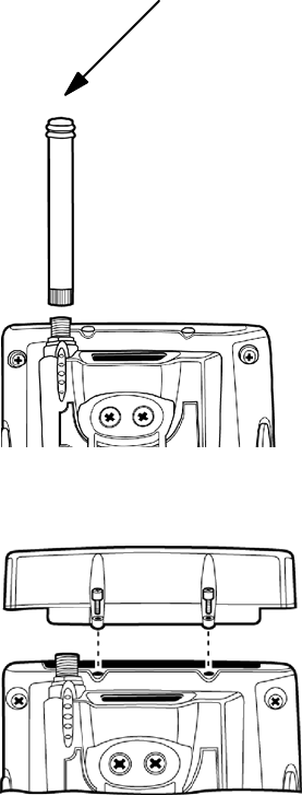
Network Support—Chapter 4
99700 Series Color Mobile Computer User’s Manual
SBlue (760/761 Computers)
GSM/GPRS International (MC45 WAN radios)
SNo Color (761 Computers)
CDMA and GSM/GPRS US/Canada (MC46 WAN radios)
SRadome (761B Computers)
GPRS EDGE only (MC75 radios)
Personal Area Networks
“Bluetooth” is the name given to a technology standard using short-range
radio links, intended to replace cables connecting portable and fixed elec-
tronic devices. The standard defines a uniform structure for a range of de-
vices to communicate with each other with minimal user effort. Its key
features are robustness, low complexity, low power, and low cost. The
technology offers wireless access to LANs, the mobile phone network, and
the internet for a host of home appliances and mobile computer interfaces.
Wireless Printing can also be done with Microsoft APIs, including Blue-
tooth extensions for Winsock, and Bluetooth virtual COM ports. Infor-
mation about other Bluetooth software is in the Bluetooth Resource Kit
and the Bluetooth Resource Kit User’s Guide via the Intermec Developer Li-
brary (IDL), which is available as a download from the Intermec web via
www.intermec.com/idl. See your Intermec representative for information.

Network SupportChapter —4
100 700 Series Color Mobile Computer User’s Manual
About the Application
Bluetooth is not started automatically by default after a cold-boot is per-
formed. To run Bluetooth, tap Start >Settings >theConnections tab >
the Bluetooth icon. The 700 Color Computer retains the Bluetooth state
when warm-boots are performed, for example:
SIf Bluetooth is active, and a warm-boot was performed, the 700 Color
Computer boots up with the Bluetooth state activated and Bluetooth
virtual COM ports (such as printing) registered. However, you must
reactivate connections, as the system does not do these automatically.
SIf Bluetooth is inactive, and a warm-boot was performed, the 700 Color
Computer boots up with Bluetooth deactivated.
Mode
The default tab activates or deactivates Bluetooth. When Bluetooth is acti-
vated, the 700 Color Computer discovers and connects to remote devices.
700 Color Screen 730 Screen
Wireless Printing
Use this tab to print via Bluetooth devices. Tap Device Discovery to dis-
cover (or scan) for remote Bluetooth devices. When the 700 Color Com-
puter is finished scanning, any newly discovered devices appear in the up-
per Devices box.
Tap Clear Devices to remove the list from the Devices box.
To print to a Bluetooth device, select any of the devices listed in the
Devices box, then tap Connect. Once connected, the selected device
moves to the lower Connected box.
To view connection information or register a COM port for a device,
from the lower Connected box, select a device, then tap Properties.See
“Properties” on the next page for information.
When done printing to a device, select that device in the Connected box,
then tap Disconnect. This moves the device in question back to the upper
Devices box.
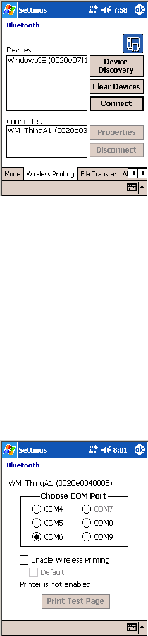
Network Support—Chapter 4
101700 Series Color Mobile Computer User’s Manual
Properties
Select a COM Port from the Choose COM Port boxtoregisterforthis
device, then check Enable Wireless Printing to complete the COM port
registration. To change your COM port selection, clear (uncheck) the En-
able Wireless Printing box, select a new COM port, then check Enable
Wireless Printing again. Choose COM Port items already in use are
grayed out.
When you enable Wireless Printing, a status message is shown near the
bottom of the screen to confirm your action. To print a test page to your
printer, tap Print Test Page.
Check Default to set this printer to identify the assigned COM Port as the
WPPort in the registry. See the Bluetooth Resource Kit User’s Guide for
more details on WPPort.
Tap ok to return to the Wireless Printing page.
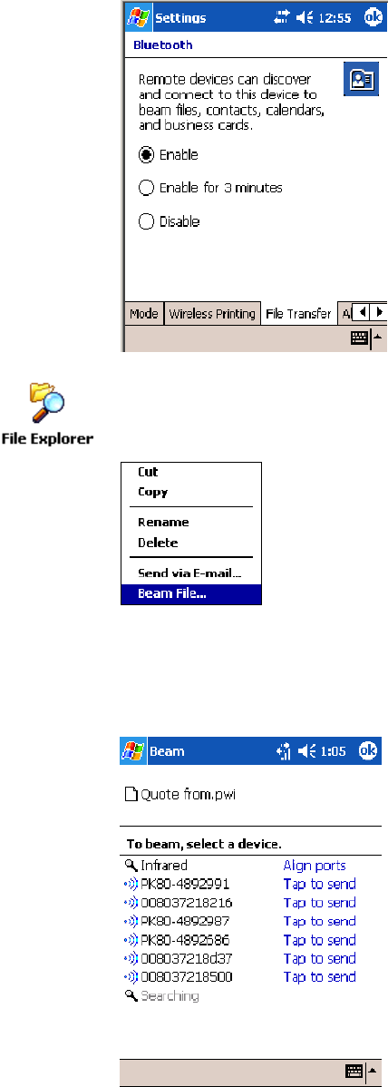
Network SupportChapter —4
102 700 Series Color Mobile Computer User’s Manual
File Transfer
Use this page to enable your unit to receive files from another Bluetooth
device, or from any device that supports this function.
This does not apply to the 730 Computer. From this point, this transfer is
similar to an IrDA file transfer. Tap Start >Programs >File Explorer,tap
to hold the file to transfer, then select Beam File from its pop-up menu.
The system searches for a list of Bluetooth devices that will accept a con-
nection from your unit. When the list is complete, tap on a device to
which to send the file. Note: in some cases, the user of the target device has to
“accept” the file before it is transmitted.
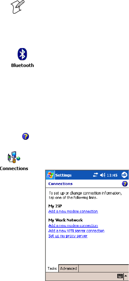
Network Support—Chapter 4
103700 Series Color Mobile Computer User’s Manual
Connecting with Bluetooth
Note: While these instructions apply to many Bluetooth devices, these in-
structions use the Nokia 3650 for example purposes.
Before you connect to the network, make sure Bluetooth is enabled on
your 700 Color Computer before discovering and connecting to remote
devices.
Tap Start >Settings >theConnections tab>theBluetooth icon. Tap On
to activate Bluetooth, then tap ok to exit the applet.
Also make sure Bluetooth is enabled on your mobile phone. For example,
with the Nokia 3650, go to its menu, select Connect >Bluetooth,thenset
My phone’s visibility to “Shown to all.”
Do the following to establish a Bluetooth connection between your 700
Color Computer and your mobile phone, then establishing a dial-up net-
working session with your wireless network. Once connected, you should
be able to browse Internet websites and use other online resources from
your 700 Color Computer.
To view additional information for any screen in the wizard or while
changing settings, tap the Help icon.
1Tap Start >Settings >theConnections tab>theConnections icon. In
My ISP,tapAdd a new modem connection.

Network SupportChapter —4
104 700 Series Color Mobile Computer User’s Manual
2Enter a name for the connection, such as “Nokia.” In the Select a mo-
dem list, select “Bluetooth,” then tap Next to continue.
3Tap New... if the phone is not listed in the known devices. Make sure
your Bluetooth device is turned on before you start the search.
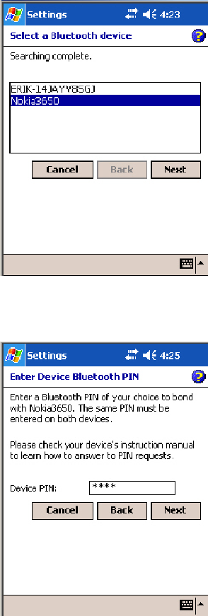
Network Support—Chapter 4
105700 Series Color Mobile Computer User’s Manual
4When the discovery of devices is complete, select your Bluetooth device,
then tap Next to continue.
5Enter the correct Device PIN on both the Bluetooth device and the 700
Color Computer, then tap Next to continue.

Network SupportChapter —4
106 700 Series Color Mobile Computer User’s Manual
6Enter a name for the device if needed, then tap Finish.
7After bonding completes, select your Bluetooth device from the list of
bonded devices, then tap Next.
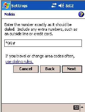
Network Support—Chapter 4
107700 Series Color Mobile Computer User’s Manual
8Enter the appropriate number as it should be dialed for your Bluetooth
connection, then tap Next to continue. Enter the user name, password,
and domain required for your Bluetooth device, then tap Finish.
Now you can establish a connection to your network via the Internet Ex-
plorer application. To disconnect, tap the Connectivity icon in the top
menu bar, then select Disconnect.
Local Area Networks
See the Developer’s Support web site for the latest information on network
adapters for your unit.
The 700 Color Computer is a versatile mobile computer that easily adds to
your wired or wireless data collection network. You can connect your 700
Color Computer to your network using either USB communications or
802.11b or 802.11b/g radio communications.
Configuring USB Communications
You can place the 700 Color Computer in a single dock, multidock, mo-
dem dock, or vehicle dock to transfer data to and receive data from anoth-
er device using USB communications. The USB cable, single dock, multi-
dock, modem dock, and vehicle dock are sold separately. For information
on accessories and how to order them, see “Accessories” on page 21.
To use USB communications with your 700 Color Computer
1Connect the dock to the USB port of the other device using an ap-
propriate USB cable.
2Make sure your USB device is configured for USB communications.
3Insert the 700 Color Computer into the dock.
4Turn on the 700 Color Computer.

Network SupportChapter —4
108 700 Series Color Mobile Computer User’s Manual
Configuring 802.11 Radio Communications
Caution: Make sure all components with antennas are at least 30 cm (1
ft) apart when power is applied. Failure to comply could result in
equipment damage.
The wireless 700 Color Computer has an internal 802.11b or 802.11b/g
radio to transfer data using wireless communications. This manual assumes
you already have set up your wireless communications network, including
your access points. If you are using a UDP Plus network, have your
Intermec Application Server communicate with a host computer. Your
700 Color Computer supports TCP/IP and UDP Plus.
Configuring the Network Parameters for a TCP/IP Network
In a TCP/IP network, the 700 Color Computer communicates with a host
computer directly using TCP/IP. The access point acts as a bridge to allow
communications between the wired and wireless networks.
1Configure the infrastructure mode, network name (SSID), host IP ad-
dress, and IP settings (if not using DHCP) on each 700 Color Comput-
er in the network.
2Configure security. Tap Start >Settings >theSystem tab>theWire-
less Network icon to access the Profile Wizard for the 802.11b or
802.11b/g radio module. Go to Appendix A, “Configurable Settings,”
for information.
Configuring the Network Parameters for a UDP Plus Network
In a UDP Plus network, the 700 Color Computer communicates with a
host computer through the Intermec Application Server. The Intermec
Application Server translates UDP Plus packets on the wireless network
into TCP/IP packets on the wired network and vice versa. The access
point acts as a bridge to allow communications between the wired and
wireless networks.
1Configure the network name (SSID), controller IP address, and IP set-
tings (if not using DHCP), and controller port (set to 5555) on each
700 Color Computer in the network.
2Configure security. Tap Start >Settings >theSystem tab>theWire-
less Network icon to access the Profile Wizard for the 802.11b or
802.11b/g radio module. Go to Appendix A, “Configurable Settings,”
for information.
The easiest way to configure the network parameters on the 700 Color
Computer is to use the Intermec Settings applet. Go to Appendix A,
“Configurable Settings.” for information.
Network Adapters
The 700 Color Computer can have up to three radios installed. The de-
fault network adapter or radio is dependent on what radios are installed in
your unit. The 700 Color Computer is capable of supporting 802.11i se-
curity requirements.

Network Support—Chapter 4
109700 Series Color Mobile Computer User’s Manual
With the NDISTRAY pop-up menu (the Network Driver Interface Speci-
fication tray application) from the System Tray, you can specify “802.11,”
“Ethernet,” or “No Networking” to load onto your 700 Color Computer
when a cold-boot is performed. When a warm boot is performed, the 700
Color Computer loads the network set just prior to the warm boot.
The 730 Computer only has the 802.11b radio and Bluetooth. It does not
have an external antenna. Other radios are not supported.
Ethernet Communications (740, 741, 750, 751, 760, 761 Computers)
Follow the steps below to start Ethernet communications on the 700 Color
Computer. If your system does not contain an 802.11b or 802.11b/g
radio, then Ethernet networking using DHCP is selected as the default.
When “Built-in Ethernet” is selected from the NDISTRAY pop-up menu,
then the Ethernet icon shown to the left appears in the System Tray as
circled in the following illustration.
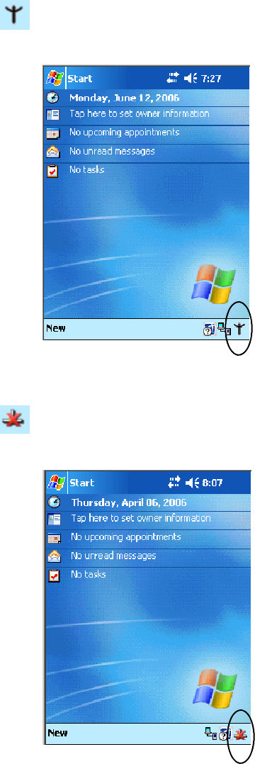
Network SupportChapter —4
110 700 Series Color Mobile Computer User’s Manual
Wireless 802.11 Communications
When “Wireless 802.11” is selected via the NDISTRAY pop-up menu,
the Wireless 802.11 antenna icon shown to the left appears in the system
tray as circled in the following illustration.
No Networking
When “No networking” is selected from the NDISTRAY pop-up menu,
the disconnected icon shown to the left appears in the system tray as
circled in the following illustration.
Network Selection APIs
The Network Selection APIs change the network adapter configuration
programmatically. Both drivers support the same IOCTL function num-
bers for loading and unloading the drivers. Go to Chapter 7, “Program-
ming,” to see the APIs.
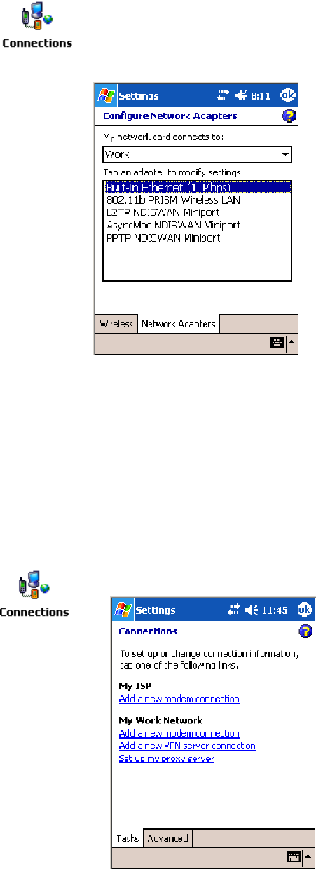
Network Support—Chapter 4
111700 Series Color Mobile Computer User’s Manual
Network Connections
From the 700 Color Computer, tap Start >Settings >theConnections
tab>theConnections icon > the Advanced tab > Network Card or the
Network Adapters tab to access the network connections for this unit.
Make the changes necessary for your network, then tap ok when finished.
Creating a Wireless Network Connection
Use the Wireless Network applet for more security choices and better
roaming behavior. See Appendix A for information.
Networks already configured are preferred networks and are listed in
Wireless networks. You can connect to only preferred networks or search
for and connect to any available network.
A wireless network can be added either when the network is detected, or
manually by entering settings information. To determine if authentication
information is needed, see your network administrator.
1Tap Start >Settings >theConnections tab>theConnections icon.
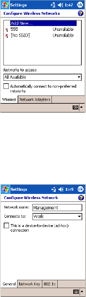
Network SupportChapter —4
112 700 Series Color Mobile Computer User’s Manual
2Tap the Advanced tab > Network Card >theWireless tab > Add New .
3Tap the General tab, then enter a network name. If the network was
detected, the network name is entered and cannot be changed.
From Connects to, select to what your network is to connect. If you
select “Work,” you can do a vpn connection or use proxy servers. If you
select “The Internet,” you can connect directly to the internet.
To connect to an ad-hoc connection, select This is a device-to-device
(ad-hoc) connection.
4Tap the Network Key tab, then do the following:
To Disable Authentication
aSet Authentication to either “Open” if WEP keys are not required;
or “Shared” when WEP keys are required for association.
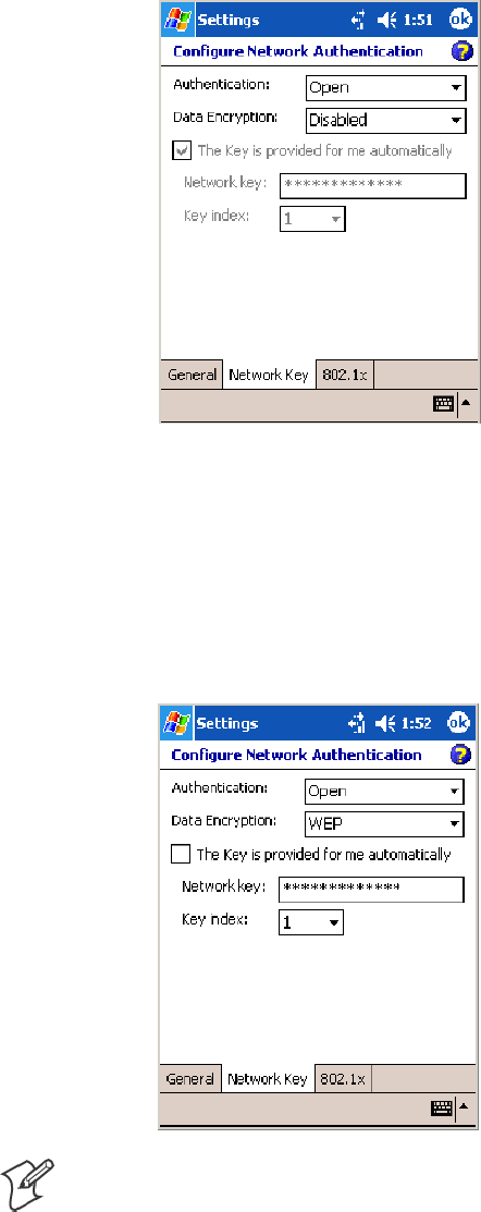
Network Support—Chapter 4
113700 Series Color Mobile Computer User’s Manual
bSet Data Encryption to “Disabled.”
To Enable WEP Encryption
aSet Authentication to either “Open” if WEP keys are not required;
or “Shared” when WEP keys are required for association.
bSet Data Encryption to “WEP.”
cTo change the network key, clear The Key is provided for me auto-
matically box, then enter the new Network key and select the ap-
propriate Key index.
Note: The following information applies when you have Enable Micro-
soft’s Wireless Zero Config checked via the Wireless Network applet (see
Appendix A, “Configurable Settings”).
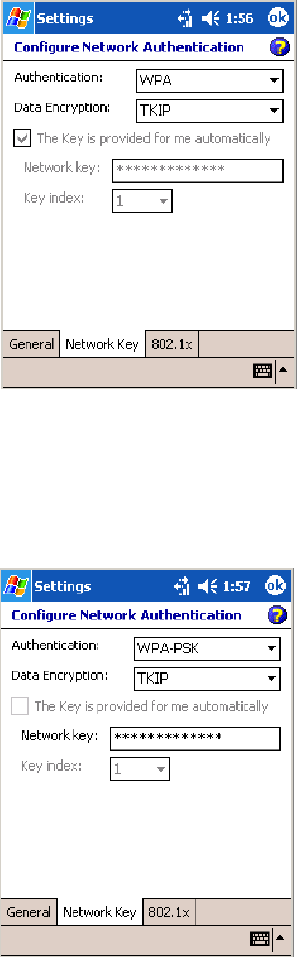
Network SupportChapter —4
114 700 Series Color Mobile Computer User’s Manual
To Enable WPA Authentication (730, 751, 751, 761 Computers)
aSet Authentication to “WPA” (see page 236).
bSet Data Encryption to either “WEP” or “TKIP” (see page 236).
To Enable WPA Authentication Using a Preshared Key (730, 741, 751, 761 Computers)
aSet Authentication to “WPA-PSK” (see page 236).
bSet Data Encryption to either “WEP” or “TKIP” (see page 236).
cEnter the new Network key.
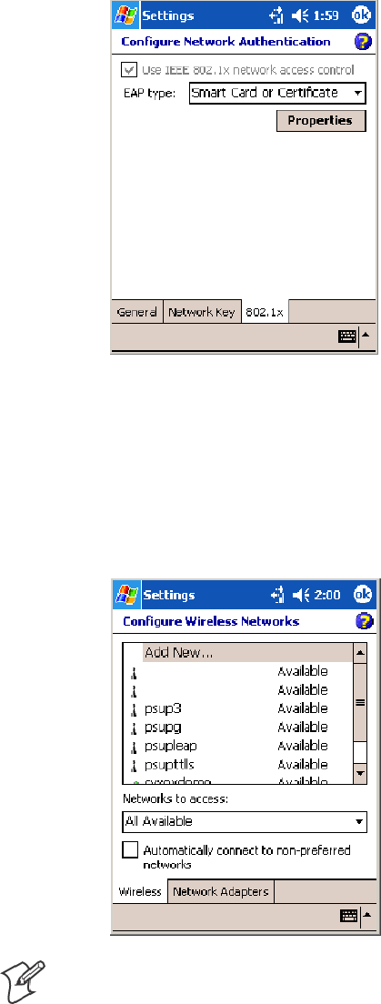
Network Support—Chapter 4
115700 Series Color Mobile Computer User’s Manual
5Tap the 802.1x tab, select either “PEAP” or “Smart Card or Certificate”
for the EAP type,thentapProperties to adjust its settings.
6Tap ok to return to the Configure Wireless Network screen.
7From the Networks to access drop-down list, select “All Available,”
“Only access points,” or “Only computer-to-computer” depending on
the type of networks to which you connect.
To connect only to networks you have already configured, clear Auto-
matically connect to non-preferred networks.Tapok to close this
screen.
Note: If you select to automatically connect to non-preferred networks,
your device detects any new networks and provide you the opportunity to
configure them.

Network SupportChapter —4
116 700 Series Color Mobile Computer User’s Manual
AutoIP/DHCP
Automatic Private IP Addressing (AutoIP) is enabled by default in
Windows Mobile 2003. To remain compatible with other versions of
Pocket PC, this setting needs to be enabled. You can configure the registry
settings in the following to set the required AutoIP/DHCP behavior:
SFor Ethernet: HKEY_LOCAL_MACHINE\Comm\LAN9001\TcpIp
SFot 802.11: HKEY_LOCAL_MACHINE\Comm\NETWLAN1\TcpIp
Other registry keys that can modify the behavior of AutoIP are as follows.
You can find the appropriate settings and behavior of each of these keys in
Microsoft Help.
SAutoInterval
SAutoMask
SAutoSubnet
SAutoIP
SAutoSeed
When a TCP/IP client cannot find a DHCP server, it generates an AutoIP
address from the 169.254.xxx.xxx block. The client then tries to check for
a DHCP server every 15 seconds and if a DHCP server is found, the client
drops the AutoIP address and uses the address from the DHCP server.
In the MSDN Windows CE documentation available out on the Micro-
soft Developer Network web site (www.msdn.com), see “Automatic Client
Configuration” for more information on AutoIP.
To disable AutoIP, set the AutoCfg registry entry to “0.” If a DHCP serv-
er cannot be found, instead of using AutoIP, the system will display the
“Unable to obtain a server assigned IP address” message.
Note: If you try to disable AutoIP using a CAB file to set the registry value
for AutoIP, remember to set the EnableDHCP value to “1” to keep
DHCP enabled
Note: To extend the number of attempts that a DHCP client makes to get
a DHCP address, use the DhcpRetryDialogue and DhcpMaxRetry registry
settings.
Note: Change the AutoInterval registry key value to make the client retry
more often to obtain a DHCP address.
Wide Area Networks
The 700 Color Computer does not support wide area networks.
Phone Applications
The following phone applications apply to certain configurations. See the
chart on page 98 to learn which applies to your 700 Color Computer.
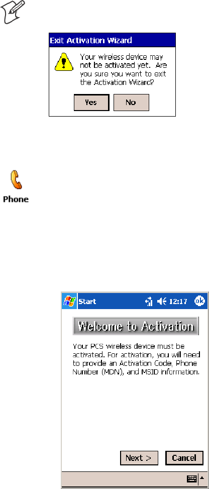
Network Support—Chapter 4
117700 Series Color Mobile Computer User’s Manual
Microsoft Phone Application (761 Computers with CDMA Radios)
With the WAN radio module installed in your 761 Computer, you can
send and receive telephone calls. Use the speaker on the back of the com-
puter as your earpiece and use the connector on the bottom of the com-
puter for your mouthpiece.
Data Provisioning (Sprint)
Note: If you wish to do this activation another time, tap Cancel to close
this wizard, then tap Yes.
It is necessary to initiate activation before using your Microsoft Phone ap-
plication. Below are the instructions:
1Tap Start >Programs >thePhone desktop icon or tap Start >Phone
from the Today screen to access the application which processes your
phone calls. Tap the Close button in the upper right corner of this ap-
plication to close.
2From the Phone application, tap Tools >Activation Wizard.
3Have your activation code, phone number (MDN), and MSID infor-
mation ready before you tap Next to continue. You can get this infor-
mation from your network provider.
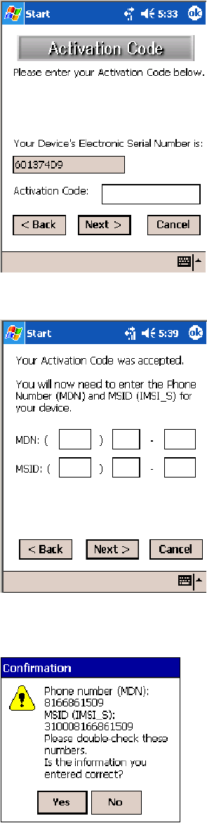
Network SupportChapter —4
118 700 Series Color Mobile Computer User’s Manual
4Enter your 6-digit activation code, then tap Next to continue.
5Enter the phone number and MSID from Sprint, tap Next to continue.
6The application prompts whether the information entered is correct. If
so, tap Yes to continue, else tap No to return to the previous screen.

Network Support—Chapter 4
119700 Series Color Mobile Computer User’s Manual
7Note that voice service is available immediately. Data service take a
minimum of four hours of activation before you can use the service. If
after four hours, a data connection is not established, see “Data Provi-
sioning” on page 117 to manually launch data provisioning.
The application acknowledges that your phone will be in service in four
hours. Tap Finish to close the wizard.
Data Provisioning (Verizon)
Note: If you wish to do this activation another time, tap Cancel to close
this wizard, then tap Yes.
It is necessary to initiate activation before using your Microsoft Phone ap-
plication. Below are the instructions:
1Tap Start >Programs >thePhone desktop icon or tap Start >Phone
from the Today screen to access the application which processes your
phone calls. Tap the Close button in the upper right corner of this ap-
plication to close.
2From the Phone application, tap Tools >Activation Wizard.
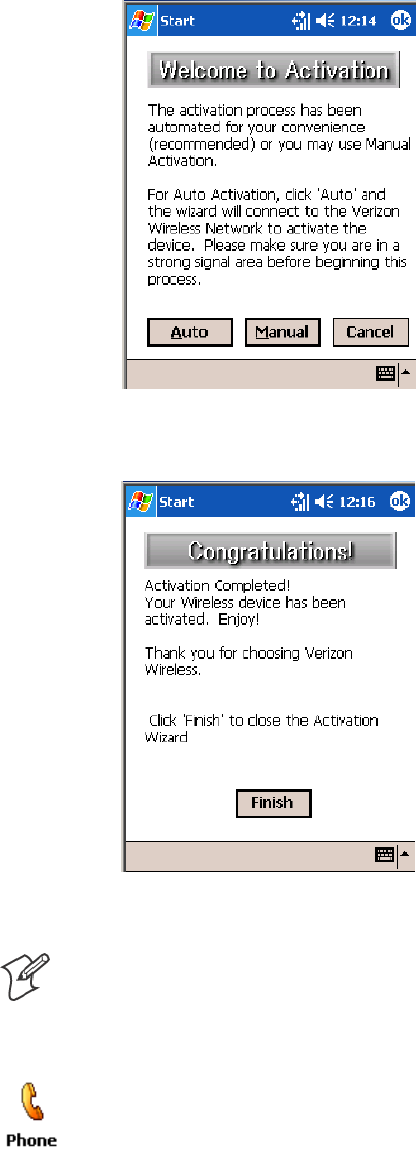
Network SupportChapter —4
120 700 Series Color Mobile Computer User’s Manual
3Tap Auto to initiate the activation.
4The application acknowledges that your phone is now in service. Tap
Finish to close the wizard.
Phone Application
Note: Wait at least four hours after Sprint activation is complete before
using this application. Data provisioning should occur automatically. Net-
work information about your 761 Computer needs to propagate through
the Sprint Network after the activation is complete.
If data provisioning does not occur automatically, tap Start >Settings >
the Personal tab>thePhone icon. Tap the Data tab, then tap Provision
to initiate a session.
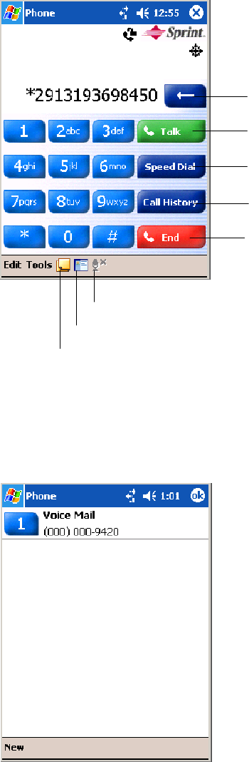
Network Support—Chapter 4
121700 Series Color Mobile Computer User’s Manual
Tap the appropriate keys to enter a telephone number, then tap Talk to
dial the number. Tap End to “hang up” the phone.
Tap this to dial the phone number
shown above the keypad.
Tap this to backspace one digit.
Tap this to select a previously
dialed number.
Tap this to view your previous calls.
Tap this to “hang up” your current
call.
Tap this to access the Contacts application.
Tap this toggle the mute option.
Tap this to access the Notes application.
Speed Dial
Tap Speed Dial to select a telephone number with which the 761 Com-
puter is to dial automatically. To add to this list, use the Contacts applica-
tion. See Chapter 2, “Windows Mobile 2003,” for more information
about the Contacts application.

Network SupportChapter —4
122 700 Series Color Mobile Computer User’s Manual
Call History
Tap Call History to note the telephone numbers that were previously
dialed from this 761 Computer.
Tools
Use the Tools menu to send a voice mail, access the Activation Wizard,
send an SMS email message, or configure phone settings.
STap Tools >Voice Mail to call and leave a voice message.
STap Tools >Activation Wizard to access the wizard with which to acti-
vate your 761 Computer. Be sure to have an activation code, a phone
number, and MSID information ready. See page 117 for instructions on
using this wizard.
Sprint Networks Verizon Networks
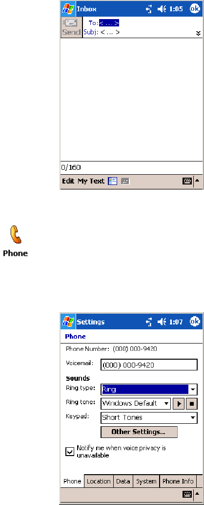
Network Support—Chapter 4
123700 Series Color Mobile Computer User’s Manual
STap Tools >Send SMS tab to access the Inbox application and send an
SMS (Short Messaging Service) message. Be sure to have an SMS num-
ber ready to send the message — this is usually the mobile phone num-
ber. See Chapter 2, “Windows Mobile 2003,” for Inbox information.
Phone Settings
Either select Tools >Options from the Phone application or select Start >
Settings >thePersonal tab>thePhone icon to access the applet.
STap the Phone tab to customize your phone settings such as the ring
type and ring tone to use for incoming calls, and the keypad tone to use
when entering phone numbers. Tap Other Settings to go to the Sounds
& Notifications applet. Select Start >Help for more information.
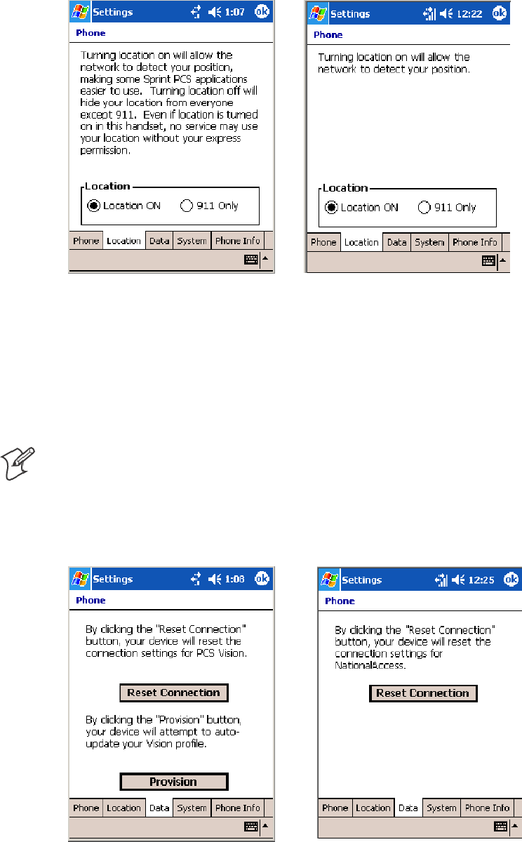
Network SupportChapter —4
124 700 Series Color Mobile Computer User’s Manual
STap the Location tab to toggle between your location being visible for
everyone to detect and hiding your location from everyone except 911.
Sprint Networks Verizon Networks
STap the Data tab to either reset your connection settings for PCS Vi-
sion or update your PCS Vision profile.
For Sprint Networks, if your 761 Computer is unable to make a data
connection and it has been more than four hours since activation, you
can launch data provisioning from this screen. Tap Provision,thenfol-
low the prompts. It takes a few minutes to set up the data connections.
Note: The data provisioning process can be automatically initiated by
the Sprint network, by attempting to make a cellular line connection to
the WAN before the 761 Computer is data provisioned, or by manually
starting the connections through this screen. Intermec recommends that
Sprint Network “push” the data provisioning to your unit. This should oc-
cur shortly after the voice activation is complete.
Sprint Networks Verizon Networks
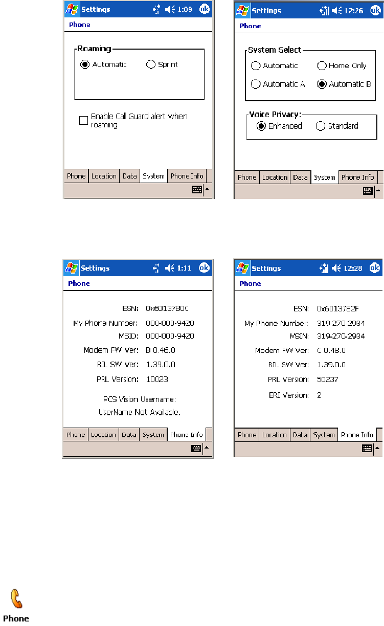
Network Support—Chapter 4
125700 Series Color Mobile Computer User’s Manual
STap the System tab to select the applicable function.
Sprint Networks Verizon Networks
STap the Phone Info tab to view the phone settings.
Sprint Networks Verizon Networks
Microsoft Phone Application (761 Computers with GSM Radios)
With the WAN radio module installed in your 761 Computer, you can
send and receive telephone calls. Use the speaker on the back of the com-
puter as your earpiece and use the connector on the bottom of the com-
puter for your mouthpiece.
Tap Start >Settings >thePhone desktopiconfromthePersonal tab or
tap Start >Phone from the Today screen to access the application which
processes your phone calls. Tap the Close button in the upper right corner
of this application to close.
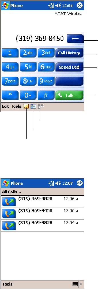
Network SupportChapter —4
126 700 Series Color Mobile Computer User’s Manual
Activation
The GSM phone is activated via a SIM card that you can purchase from
your network provider.
Phone Application
Tap the appropriate keys to enter a telephone number, then tap Talk to
dial the number.
Tap this to dial the phone number
shown above the keypad.
Tap this to backspace one digit.
Tap this to select a previously
dialed number.
Tap this to view your previous calls.
Tap this to access the Contacts application.
Tap this toggle the mute option.
Tap this to access the Notes application.
Call History
Tap Call History to note the telephone numbers that were previously
dialed from this 761 Computer.
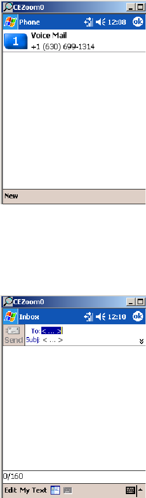
Network Support—Chapter 4
127700 Series Color Mobile Computer User’s Manual
Speed Dial
Tap Speed Dial to select a telephone number with which the 761 Com-
puter is to dial automatically. To add to this list, use the Contacts applica-
tion. See Chapter 2, “Windows Mobile 2003,” for more information
about the Contacts application.
Tools
Tap Tools >Send SMS tab to access the Inbox application and send an
SMS (Short Messaging Service) message. Be sure to have an SMS number
ready to send the message — this is usually the mobile phone number. See
Chapter 2, “Windows Mobile 2003,” for information about Inbox.
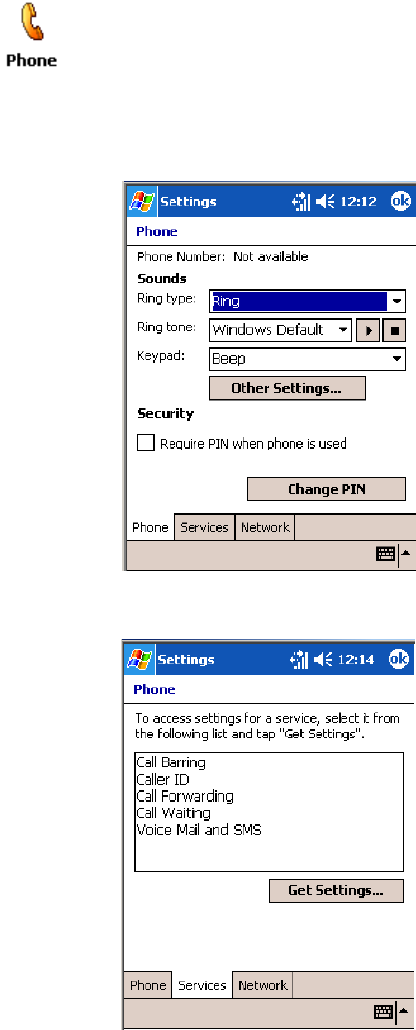
Network SupportChapter —4
128 700 Series Color Mobile Computer User’s Manual
Phone Settings
Either select Tools >Options from the Phone application or select Start >
Settings >thePersonal tab>thePhone icon to access the applet.
STap the Phone tab to customize your phone settings such as the ring
type and ring tone to use for incoming calls, and the keypad tone to use
when entering phone numbers. Tap Other Settings to go to the Sounds
& Notifications applet.
STap the Services tab to access settings for any of the provided services.
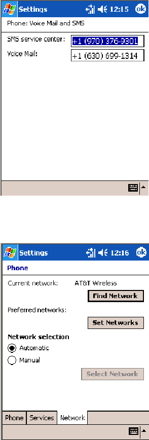
Network Support—Chapter 4
129700 Series Color Mobile Computer User’s Manual
Tap any of the settings, then tap Get Settings.Makeyourchanges,then
tap ok to return to the Settings screen. Below is a sample Settings
screen.
STap the Network tab to find, set, or select the type of network on
which this phone is to communicate.
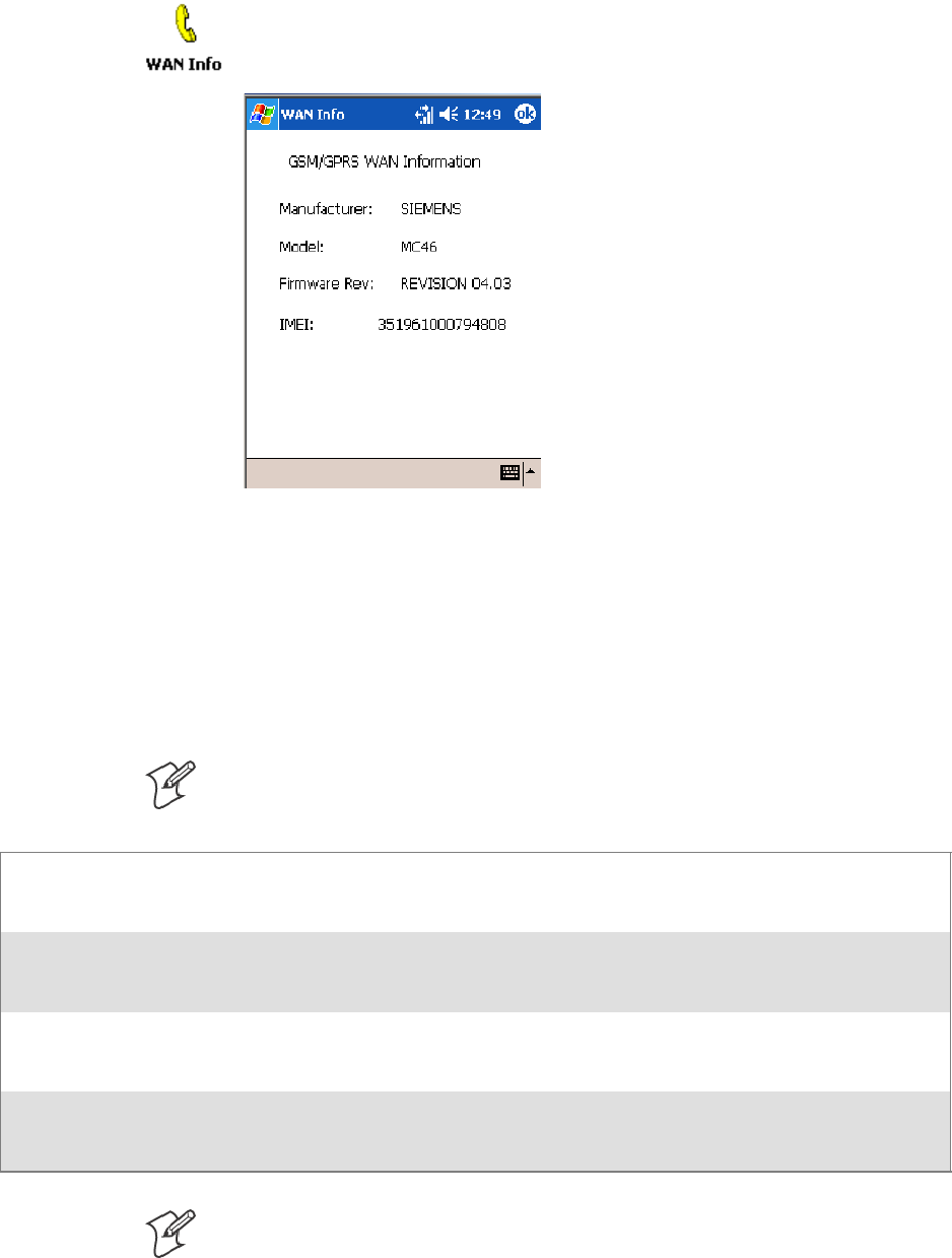
Network SupportChapter —4
130 700 Series Color Mobile Computer User’s Manual
Phone Information
To learn the latest phone settings, including the manufacturer, model,
firmware rev, and IMEI, select Start >Settings >theSystem tab, then tap
the WAN Info desktop icon. Tap ok when finished.
SB555 Watcher (760 Computers with CDMA Radios)
The SB555 Watcher program is used on the 760 Computer with CDMA
radios only. Use this primarily to activate the WAN radio. Once the WAN
radio is activated, you can remove the SB555 Watcher program from the
760 Computer.
This tells you how to set up your CDMA radio in your 760 Computer.
Below are terms to familiarize you with CDMA radio technology:
Note: Set up and provision information is also available in the 700 Color
CDMA Radio Setup Quick Start Guide P/N: 962-054-063.
Activation The process of programming the radio with the lock code (MSL) and phone number (MIN) to
allow it to communicate on the provider’s network. Once activation is complete you can make
voice calls (if enabled by the carrier) with the mobile computer.
Data Provisioning The process of activating the ability for the CDMA radio to establish data connections, such as
connecting to the Internet. The CDMA radio makes data connection only after it is activated
and data provisioned.
NID (Network ID) A numeric value programmed into the CDMA radio at the factory or during the activation
process. Your carrier may or may not use this value, but your carrier may provide this for ac-
tivation purposes.
SID (System ID) A numeric value programmed into the CDMA radio at the factory or during the activation
process. This number is used by your carrier to determine if the radio belongs to its CDMA
network. Your carrier may provide this number for activation purposes.
Note: Descriptions in this chapter are for Sprint PCS, Bell Mobility, Te-
lus, and Verizon Networks versions of the SB555 Watcher program. Oth-
er carriers may be added pending regulatory and carrier approval.
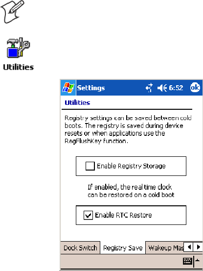
Network Support—Chapter 4
131700 Series Color Mobile Computer User’s Manual
Copying CDMA Radio Module CAB Files from Intermec Web Site
Copy CAB files from the Intermec web site at www.intermec.com onto
your desktop. Intermec recommends one of two methods with which to
load these CAB files onto your 760 Computer:
Svia the Microsoft ActiveSync application
Svia a CompactFlash or Secure Digital storage card. See Chapter 3,
“Installing Applications,” for information about these methods.
Via Microsoft ActiveSync
You can transfer files from your desktop to your 760 Computer via Micro-
soft ActiveSync. See Chapter 2,“Windows Mobile 2003” for more infor-
mation about ActiveSync.
1Obtain software from the Intermec web site as described earlier. Down-
load the software to any location on your 760 Computer, such as the
Temp folder via the My Device root location.
2Tap the carrier CAB file to install the application.
3Go to “Finishing the Installation” on page 132.
Via a CompactFlash or Secure Digital Storage Card
Note: These instructions are based on default locations. You can change
the location to which to copy your CAB files.
1Make sure the Registry Restore feature on your 760 Computer is dis-
abled. Select Start >Settings >theSystem tab. Tap the Utilities desk-
top icon, the Registry Save tab, then clear the Enable Registry Save box.
2Copy the CAB files for your carrier to your CompactFlash or Secure
Digital storage card after downloading it from the web site.
3Cold-boot your 760 Computer. Remove the AB10 battery pack and
press the reset button in the bottom of the battery compartment.
4Go through the normal getting started steps detailed in your 700 Color
CDMA Radio Setup Quick Start Guide.
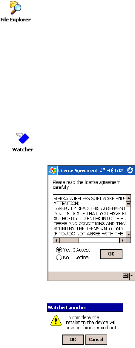
Network SupportChapter —4
132 700 Series Color Mobile Computer User’s Manual
5Install the CompactFlash or Secure Digital memory card into the card
slot in your 760 Computer. Note that if you do not want the CAB files
erased after installation, set the CAB file attributes to “read-only” after copy-
ing them to the storage card.
6Tap Start >Programs >theFile Explorer icon on the 760 Computer.
7Tap the pull-down menu for My Documents and tap the My Device
root location.
8If you are using a CompactFlash storage card,
tap Storage Card.
If you are using an Secure Digital storage card,
tap SDMMC Disk.
9Scroll down, tap the Sprint Watcher CAB file to install the application.
Finishing the Installation
Do the following to run the SB555 Watcher application. Be sure to do
step 1 as it is important to perform a warm-boot on your 760 Computer.
Upon restart, the Watcher application sets up on the 760 Computer for
activation.
1Tap Start >Programs >theWatcher icon.
2Tap Yes, I accept to accept the license agreement, tap OK to continue.
Note this license agreement does not appear again after this installation.
3Tap OK for the 760 Computer to perform a warm-boot.

Network Support—Chapter 4
133700 Series Color Mobile Computer User’s Manual
Activation
Note: Set the date and time before doing this activation.
SB555 Watcher is for activation and data provisioning. Once you enable
voice capability, data capability, or both depending on the carrier, remove
this program from the system by cold-booting your computer.
Do not use the SB555 Watcher to make data/voice calls on a daily basis:
SThe SB555 Watcher application is a third-party application unaware of
certain power management methods used in your 760 Computer. Therefore,
the application consumes more power than necessary.
SThe application size consumes memory better used for application data.
The process of setting up the account with your carrier and enabling the
CDMA WAN radio in your 760 Computer is called activation. To proper-
ly function, program the CDMA device with the necessary information
and set up the network carrier account. If either piece has errors, the de-
vice does not function on the CDMA network.
The CDMA radio is pre-programmed for a specific carrier, such as Sprint,
Telus, Bell Mobility, Verizon, etc.). Therefore, information about your
radio should already be in your carrier’s database.
You need to notify the carrier and set up mobile accounts for each unit
you are activating. The Electronic Serial Number (ESN hex 63xxxxxx)
that you need to supply to your carrier is located in two places:
SOn the outside of the 760 Computer shipping box.
SOn the inside of the 760 Computer battery compartment. The label
includes the term “ESN” and a bar code along with the serial number.
The ESN comes in both decimal and hexadecimal formats. Most carriers
accept either format, but with a preference for the decimal format. You
only need to provide one number to your carrier.
SThe decimal format consists of 11 digits, beginning with “099.”
SThe hexadecimal format is an 8-digit number, beginning with “63.”
Accounts for Verizon and Sprint carriers can be set up for data only. Cana-
dian carriers (Telus and Bell Mobility) can be set for data only, voice only,
or both voice and data. This is determined by your application and the
services your carrier offers.
After the all ESNs are provided to the carrier and the carrier has estab-
lished the accounts, you will be provided with the lock codes and tele-
phone numbers needed to complete the activation process. You use the
SB555 Watcher program to accomplish this task. Note this for future use.
Note: Ensure that you receive a spreadsheet with your order that calls out
all ESNs in both decimal and hexadecimal formats.
Note: Keep the activation information for your devices in a safe, accessible
place should you have any future issues.
Note: Not all of the elements listed are required by all service providers.
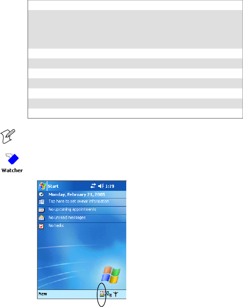
Network SupportChapter —4
134 700 Series Color Mobile Computer User’s Manual
ESN of the modem
Lock/ActivationCode(maybetermedoneofthefollowing):
SMSL — Master Subsidy Lock
SOTSL — OneTime Subsidy Lock
SSPC — Service Provisioning Code
SOTKSL — One Time Key Subsidy Lock
SID (System ID)
NID (Network ID)
User Name
Password
MIN
MSD
MDN
Note: The activation process for your Watcher version may vary from the
following steps. Thus, you may not have to do all of them.
1Tap Start >Programs >theWatcher icon or tap the Watcher icon from
the NDISTRAY via the Today screen (circled in the following illustra-
tion) to launch the SB555 Watcher program.
2The Activation Wizard should start automatically. If not, then tap
Admin >Activation Wizard from the bottom of the screen.
3Tap Next to move from one screen prompt to the next.
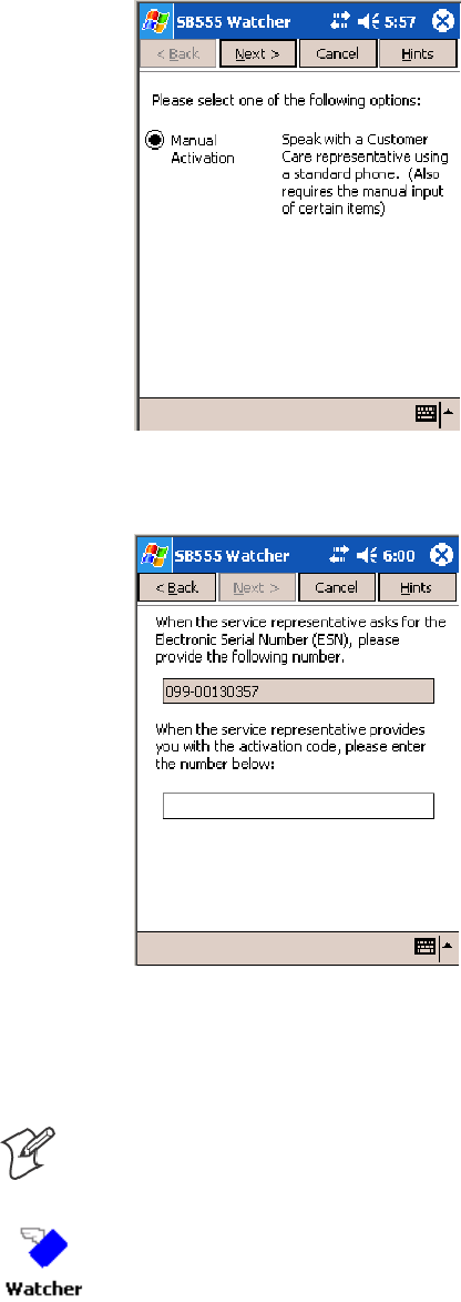
Network Support—Chapter 4
135700 Series Color Mobile Computer User’s Manual
4When you reach the Activation screen, select Manual Activation.
5At the appropriate screen, enter the Activation Code (OTSL, MSL,
OTKSL, or SPC) provided by your carrier and tap Next.
6Enter the phone number provided when your 760 Computer was acti-
vated and tap Next.
Verizon Automated Activation Process
Note: This process takes approximately 60 seconds.
Do the following to activate Verizon on your 760 Computer:
1Tap Start >Programs >theWatcher icon.

Network SupportChapter —4
136 700 Series Color Mobile Computer User’s Manual
2Tap Yes, I accept to accept the license agreement, tap OK to continue.
Note this license agreement does not appear again after this installation.
3Select OK to initiate the warm-boot, then after the warm-boot, start the
Watcher program again, select Automated Activation,thenclickNext.
Note: YoumustbeintheVerizoncoverageareatoactivateyour760
Computer and only in the location of intended use.
4Click Next,clickNext again to dial the number displayed on the screen.
5The activation process starts automatically.
6You will see a series of unlock codes on your screen.
7Click the Connect button to connect to the carrier’s network.
8Select Start >Internet Explorer, then choose a web site. Your unit is
now successfully activated.
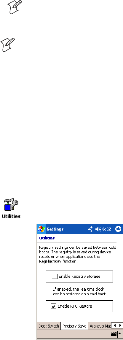
Network Support—Chapter 4
137700 Series Color Mobile Computer User’s Manual
9Perform a cold-boot on your 760 Computer to uninstall the Watcher
application, which is intended for activation purposes only. Use the fol-
lowing for establishing and maintaining connection to the WAN radio:
SCustom application using Intermec WWAN Toolkit API
SCustom customer application using Connection Manager Interface
Note: When connecting to the WAN radio via Pocket PC Connection
Manager, use the 10-digit phone number@vzw3g.com for the user
name (such as 1234567890@vzw3g.com) and “vzw” for the password.
Sprint Automated Activation Process
Note: Sprint PCS uses a data provisioning method termed IOTA (Internet
Over The Air) to complete its activation and data enablement. These steps
detail how to properly activate and data provision your 760 Computer.
1Give Sprint your ESN (either on the box or on a label inside the battery
compartment), rate plan, and account information. The label would in-
clude the term “ESN” and a bar code along with the serial number.
2Sprint provides you with the following for each ESN:
SMDN, such as 214-555-5555
SMSID, such as 214-555-5555
SMSL/OTKSL (Activation Code), such as 945614
SNAI (Network Access Identifier), such as the following:
CustomerName103@sprintpcs.com
Use a Secure Digital storage card with only the Sprint_Watcher_PPC_
2002-03xxx.CAB file in the “\SDMMC\Cabfiles” folder. Other CAB files
in the “\SDMMC\Cabfiles” folder may cause problems with testing, re-
move or uninstall these before proceeding. At least 80% (4 of 5 bars)
CDMA signal strength for a successful over-the-air activation.
Download and Activate Sprint Watcher
1Make sure the Registry Restore feature on your 760 Computer is dis-
abled. Select Start >Settings >theSystem tab. Tap the Utilities desk-
top icon, then the Registry Save tab. Clear Enable Registry Save.
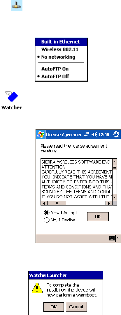
Network SupportChapter —4
138 700 Series Color Mobile Computer User’s Manual
2Perform a cold-boot on your 760 Computer, then go through the nor-
mal Pocket PC set-up (i.e. Align Screen etc.).
3Important! Set the Date and Time.
4Tap the Sprint_Watcher_PPC_2002-03xxx.CAB file to perform the
installation.
5Perform a warm-boot on your 760 Computer to load the CAB file.
6From the Today screen, tap the LAN Network icon in the System Tray.
7In the NDISTRAY pop-up menu (the Network Driver Interface Speci-
fication tray application), select No Networking and Auto FTP Off.
Tap anywhere on the screen to close the menu.
8Tap Start >Programs >theWatcher icon to launch the SB555 Watch-
er program.
9Tap Yes, I accept to accept the license agreement, then tap OK to con-
tinue. This license agreement does not appear again after this installation.
Tap OK for the 760 Computer to perform a warm-boot and complete the
installation.
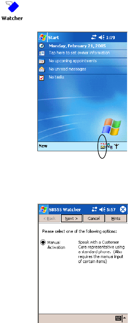
Network Support—Chapter 4
139700 Series Color Mobile Computer User’s Manual
Using Sprint Watcher
Before you start using the Sprint Watcher application, make sure you
match the correct ESN with each 760 Computer and that you have at least
80% CDMA signal strength.
TheESNthatyougivetoyourprovideriseitherontheboxoronalabel
inside the battery compartment. The label would include the “ESN” term
and a bar code along with the serial number.
1Tap Start >Programs >theWatcher icon or tap the Watcher icon from
the NDISTRAY via the Today screen (circled in the following illustra-
tion) to launch the SB555 Watcher program.
2If your 760 Computer was not previously activated, Watcher automati-
cally starts the Activation Wizard. Otherwise, select Manual Activation
to continue.
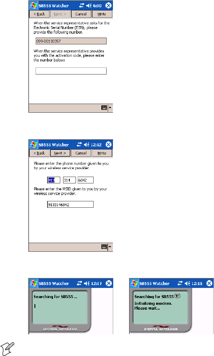
Network SupportChapter —4
140 700 Series Color Mobile Computer User’s Manual
3Enter the MSL or lock code received from Sprint.
4Enter the phone number (MIN) and MSID received from Sprint.
These numbers may be the same.
5After entering the phone number and MSID, the modem then resets
and the Watcher application displays the screens shown here:
Note: If the “searching for SB555” screen does not proceed to the next
screen after 30-40 seconds, perform a warm-boot on your 760 Comput-
er, then restart the Watcher program.
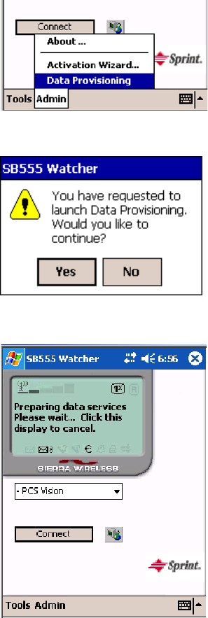
Network Support—Chapter 4
141700 Series Color Mobile Computer User’s Manual
Data Provisioning
At this point, the activation on the Sprint network is complete. It is rec-
ommended by Sprint to wait before you launch data provisioning to allow
time for the activation to propagate through your Sprint network.
Before you manually launch data provisioning, wait at least 30 minutes. In
some cases, you may have to wait up to two hours.
1If Data Provisioning does not start automatically, select Admin >Data
Provisioning from the bottom menu bar.
2Tap Yes to proceed with data provisioning.
3Activation over the air typically takes 1–20 minutes.
If data provisioning fails, do the following:
SIf Data Provisioning fails and the message “could not prepare data ser-
vices, please contact Sprint” displays, retry the Data Provisioning step by
tapping the “Admin” menu icon at the bottom of the Watcher screen.
Select “Data Provisioning...” and answer “yes” to the request.

Network SupportChapter —4
142 700 Series Color Mobile Computer User’s Manual
SIf after several attempts to complete the Data Provisioning over the air,
it may be necessary to manually enter the data activation method.
SGo to Intermec Knowledge Central www.intermec.com, then select Ser-
vice & Support >Knowledge Central) to learn about manual activa-
tion. The article (number 5749) is titled How to Manually Activate a
Sprint CDMA WAN Radio in the 760 Device.
4The following screen appears once data provisioning is complete:
5Test the data connection by tapping on the “connect” button to make a
data connection to the network. Watcher progresses through the follow-
ing two screens. Once you see the second screen you know that your
mobile computer has successfully connected to the 1XRTT network.
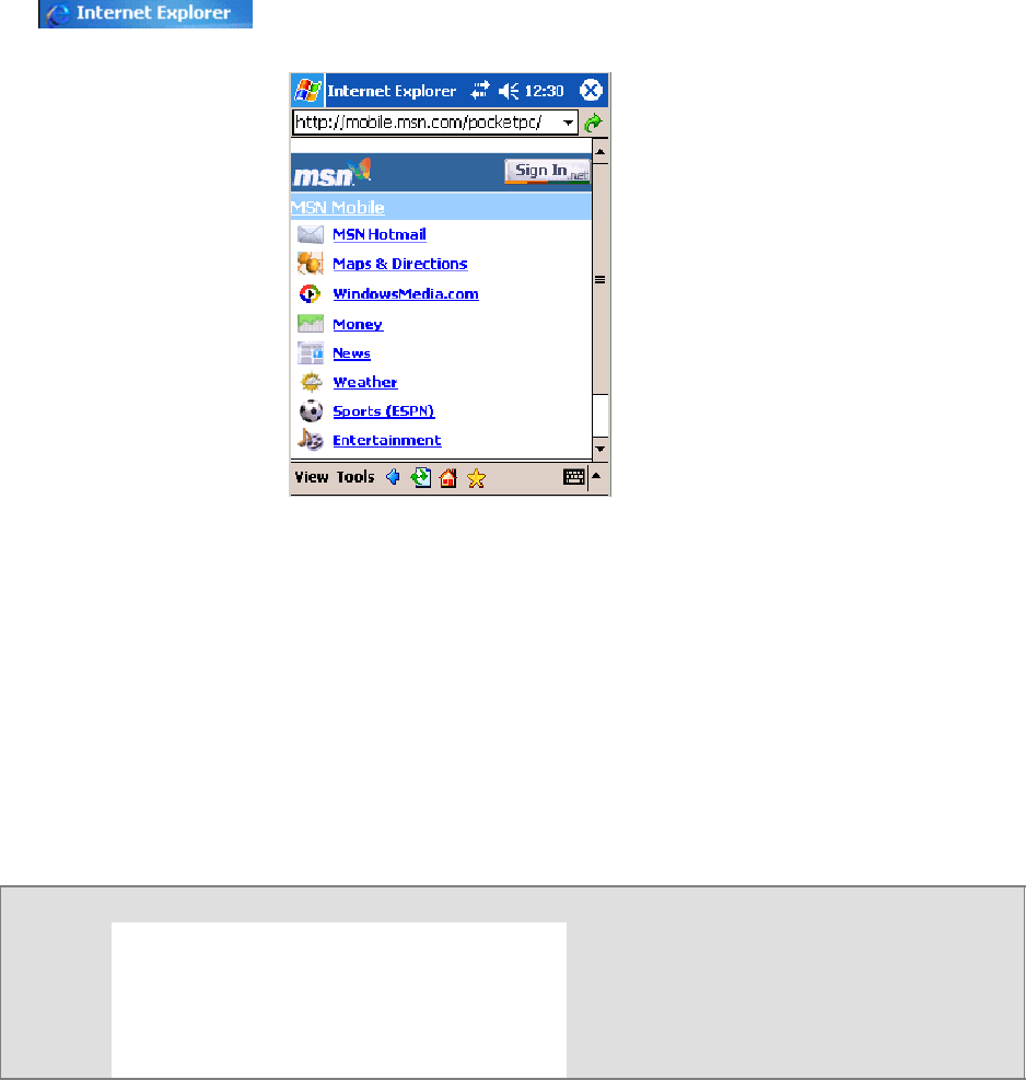
Network Support—Chapter 4
143700 Series Color Mobile Computer User’s Manual
6Select Start >Internet Explorer,thentapPocket Internet Explorer to
choose a web site. Your unit is now successfully activated.
Perform a cold-boot on your 760 Computer to uninstall the Watcher ap-
plication. Watcher is intended for activation purposes only. Use the fol-
lowing to establish and maintain connection to the WAN radio:
SCustom application using Intermec WWAN Toolkit API
SCustom customer application using Connection Manager Interface
Telus and Bell Mobility Activation
Activation of Bell Mobility and Telus are similar to the first portion of the
Sprint activation process. Follow the instructions for manual activation
using the Bell Mobility Watcher.CAB or Telus Watcher.CAB file to install
the applicable application. Enter the activation lock codes and phone num-
bers as requested.
Bell Mobility Telus
Username 10 digit phone
number@1xbell.ca
10-digit phone
number@1x.telusmobility.com
Password Original Voice Mail system password (usually a 4
digit #) available from activating organizations.
The 11-digit ESN printed inside the 760 Comput-
er battery compartment, begins with 099.
SID 16420 16422
AT Command Interface (760 Computers)
This interface specification is based on the following recommendation:
SETSI GSM 07.05:
European Digital Cellular Telecommunication System (phase 2)
Use of DTE-DCE interface for Short message and cell broadcast service.
SETSI GSM 07.07:
European Digital Cellular Telecommunication System (phase 2)
AT command set for GSM Mobile Equipment.
SITU-T Recommendation V.25 ter
Serial asynchronous automatic dialing and control.
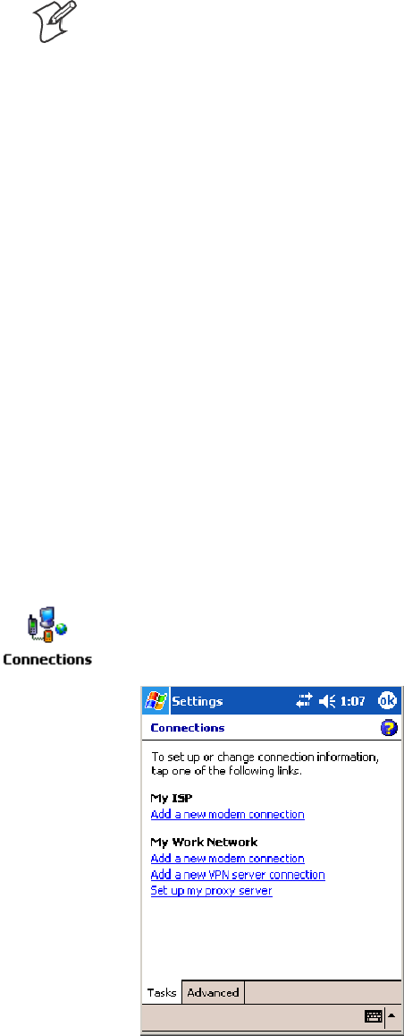
Network SupportChapter —4
144 700 Series Color Mobile Computer User’s Manual
Note: You need the Adobe Acrobat Reader application to view a PDF doc-
ument. Go to www.adobe.com/prodindex/acrobat/readstep.html to install
or download the latest Adobe Acrobat Reader.
Command Set for Sierra Wireless SB555
Use the AT command interface from Sierra Wireless to program the
CDMA/1xRTT SB555 radio module. Documentation for this interface is
available via the following URL. Click the “General AT command refer-
ence” link for a PDF document, which is 680 KB in size.
Command Set for Siemens MC45, MC46, or MC75
Use the MC45, MC46, or MC75 AT command interface from Siemens
AG to program the GPRS/GSM MC45, MC46, or MC75 radio module.
The following documentation is available either from Intermec or from
Siemens AG. Contact either your Intermec representative or the Siemens
AG support personnel for information.
SMC45 Siemens Cellular Engine AT Command Set
SMC46 Siemens Cellular Engine AT Command Set
SMC75 Siemens Cellular Engine AT Command Set
Testing the AT Commands (760, 761, 761B)
These commands can be sent to either WAN radio by setting up a dial-up
networking connection. Do the following to initiate this connection and
test these commands to your radio. These screens are from a 760 Computer.
1From the 760, 761, or 761B Computer, select Start >Settings >the
Connections tab > Connections.UnderMy ISP,tapAdd a new mo-
dem connection.

Network Support—Chapter 4
145700 Series Color Mobile Computer User’s Manual
2Enter a name for the connection, select the appropriate modem (as
listed here) from the Select a modem drop-down list, then tap Next to
continue.
S760 Computers “WANA on COM4”
S761 Computers “WANB on COM5”
S761B Computers “Virtual WANB”
3Enter a phone number as it should be dialed, then tap Next to continue.
Select Start >Help for more information or tap use dialing rules to
make modifications. Note that this screen may vary based on dialing rules.
Note that when you make a manual dial-up connection, a number is
not required. You may type in any number with at least one digit.

Network SupportChapter —4
146 700 Series Color Mobile Computer User’s Manual
4Tap Advanced to adjust the baud rate.
5Select the appropriate baud rate (as listed here) from the Baud rate
drop-down list.
S760 Computers 115200
S761 Computers 57600
S761B Computers 110

Network Support—Chapter 4
147700 Series Color Mobile Computer User’s Manual
6Tap the Port Settings tab, check Enter dialing commands manually,
tap ok,thentapFinish to return to the Connections screen.
7Tap Manage existing connections from the Connections page, press
and hold the new connection for a pop-up menu, then tap Connect to
initiate the connection.
8Wait about ten seconds for the Network Log On screen, then tap OK.
You do not need to enter information within the Network Log On screen.
Use either the onscreen keyboard, or press the keys to type any of the AT
commands provided. Press or tap Enter to send each command. The re-
sults of each command sent will print onscreen. Note that each “AT” com-
mand must start with the “at” characters.
STo see what you typed onscreen, type “ate1” to initiate the AT Echo
command, then press Enter.
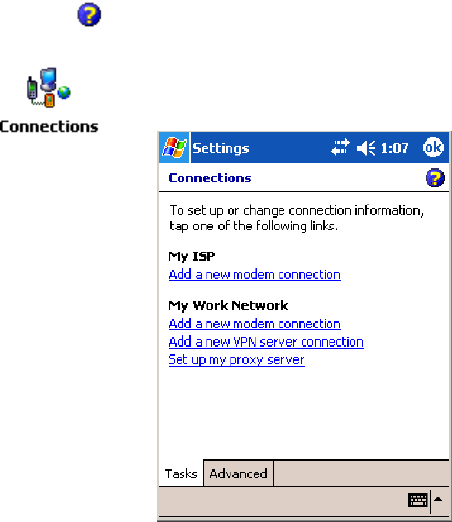
Network SupportChapter —4
148 700 Series Color Mobile Computer User’s Manual
Remote Access (Modems)
You can set up connections to the Internet and corporate network at work
to do such activities as browsing the Internet or intranet, sending and re-
ceiving e-mail and instant messages, and synchronizing information using
ActiveSync. Connections can be made using a wireless network.
Your 700 Series Computer has two groups of connection settings: My ISP
and My Work Network. Use My ISP settings to connect to the Internet.
Use My Work Network settings to connect to any private network.
SMy ISP: Once connected, you can send and receive e-mail messages by
using Inbox and view Web or WAP pages by using Pocket Internet Ex-
plorer. The communication software for creating an ISP connection is
already installed on your 700 Series Computer. Your service provider
provides the software needed to install other services, such as paging and
fax services. If this is the method you want to use, see “Connecting to
an Internet Service Provider” below.
SMy Work Network: Connect to the network at your company or orga-
nization where you work. Once connected, you can send and receive
e-mail messages by using Inbox, view Web or WAP pages by using
Pocket Internet Explorer, and synchronize with your desktop. If this is
the method you want to use, see “Connecting to Work” on page 151.
Connecting to an Internet Service Provider (ISP)
You can use your ISP connection to do e-mail and Web or WAP pages.
Get your dial-up access telephone number, user name, and password from
your ISP. Note some require additional information, such as MSN/username.
To see more information regarding any screen in the wizard or while
changing settings, tap the Help icon.
1Tap Start >Settings >theConnections tab>theConnections icon. In
My ISP,tapAdd a new modem connection.

Network Support—Chapter 4
149700 Series Color Mobile Computer User’s Manual
2Enter a name for the connection, such as “ISP Connection.” If using an
external modem with a cable, select “Hayes Compatible on COM1”
from the Select a modem list. Tap Next to continue.
3Enter the access phone number, then tap Next.
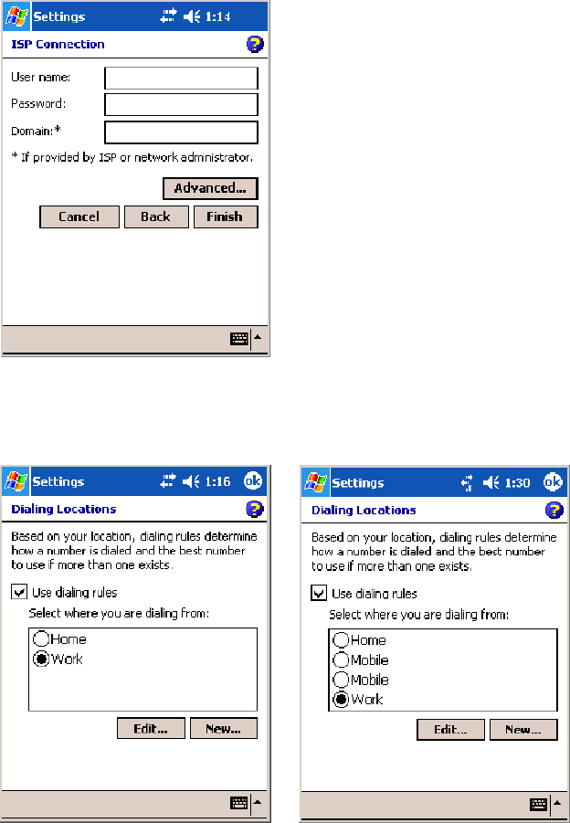
Network SupportChapter —4
150 700 Series Color Mobile Computer User’s Manual
4Enter the user name, password, and domain (if provided by an ISP or
your network administrator), then tap Finish.
5Tap the Advanced tab from the Connections screen, then tap Select
Location to specify your current location. These settings apply to all
connections. Tap Use dialing rules,tapOK,then tap Edit to continue.
730, 740, 750, 760 Screens 741, 751, 761 Screens
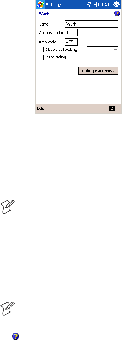
Network Support—Chapter 4
151700 Series Color Mobile Computer User’s Manual
6Specify your current phone type. If your phone type is pulse dialing,
check the Pulse dialing box. If your type is tone dialing (as most phone
lines are), then clear the Pulse dialing box. Continue to tap ok to close
each page and return to the Settings page.
To start the connection, use one of the following programs:
SSend and receive e-mail messages by using Inbox. Before you can use
Inbox, you need to provide the information it needs to communicate
with the e-mail server.
SVisit Web and WAP pages by using Pocket Internet Explorer. For more
information, see “Pocket Internet Explorer” on page 79.
SSend and receive instant messages with MSN Messenger. For more in-
formation, see “MSN Messenger” on page 73.
Note: To change modem connection settings in My ISP, tap Manage
existing connections. Select the desired modem connection, tap Settings,
and follow the instructions on the screen.
Connecting to Work
If you have access to a network at work, you can send e-mail messages,
view intranet pages, synchronize your 700 Color Computer, and possibly
access the Internet. You can connect to work by creating a modem connec-
tion via a RAS (Remote Access Server) account. Before you can create this
modem connection, your network administrator needs to set up a RAS
account for you. Your network administrator may also give you Virtual
Private Network (VPN) settings.
Note: To change modem connection settings in My Work Network, tap
Manage existing connections. Select the desired modem connection, tap
Edit, and follow the instructions on the screen.
To view additional information for any screen in the wizard or while
changing settings, tap the Help icon.
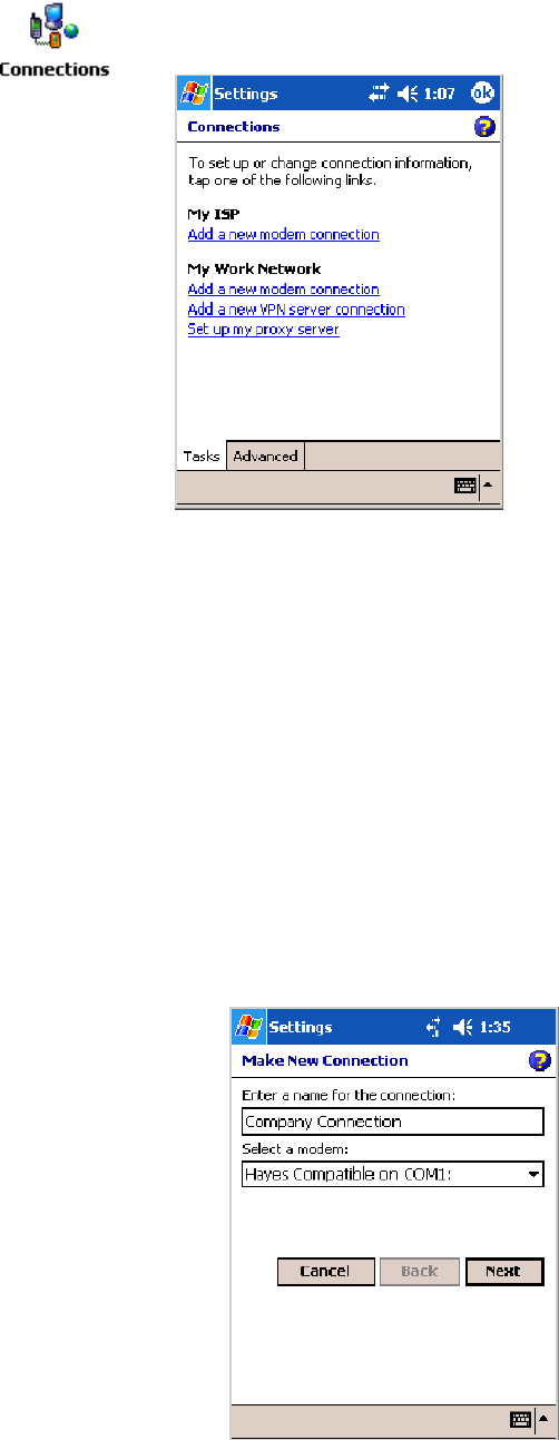
Network SupportChapter —4
152 700 Series Color Mobile Computer User’s Manual
1Tap Start >Settings >theConnections tab>theConnections icon. In
My ISP, tap Add a new modem connection.
2Enter a name for the connection, such as “Company Connection.” In
the Select a modem list, select your modem type, then tap Next to con-
tinue. If your modem type does not appear, try reinserting your 700
Color Computer into your modem dock.
SIf using an external modem connected to your 700 Computer with a
cable, select “Hayes Compatible on COM1.”
SIf using any type of external modem, select the modem by name. If a
listing does not exist for your external modem, select “Hayes Com-
patible on COM1.”
SWireless connections can be made via a mobile phone network:
SIf making a circuit-switched data connection, select “Cellular
Line.”
SIf using GPRS/EDGE, tap “Cellular Line (GPRS).”
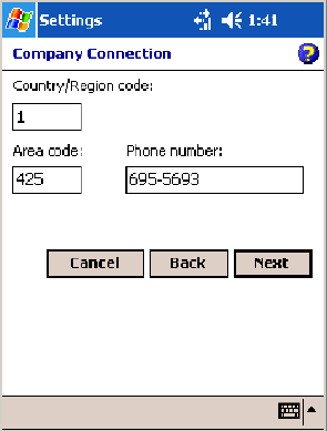
Network Support—Chapter 4
153700 Series Color Mobile Computer User’s Manual
3Enter the access phone number, using some of the following guidelines.
If you know part of the phone number changes frequently as you travel,
create dialing rules to avoid creating numerous modem connections for
the same phone number. For more information, tap Use Dialing Rules.
SEnter the phone number exactly as you want it dialed. For example,
if you call from a business complex or hotel that requires a nine be-
fore dialing out, enter “9” in front of the phone number.
SEnter the APN provided by your mobile phone service provider.
SWhen using dialing rules, phone numbers are entered differently. To
use additional numbers, such as a “9” to dial from an office complex
or hotel, you must use additional dialing rules or change dialing pat-
terns. See “Create Dialing Rules” via your online help for information.
aIn the Country/Region box, enter the appropriate code when dial-
ing internationally. For more information, contact an operator at
your local phone company.
bIn the Area code box, enter the area code. Area codes are not need-
ed in all countries.
cEnter the main phone number, then tap Next to continue.

Network SupportChapter —4
154 700 Series Color Mobile Computer User’s Manual
4If necessary, enter the user name, password, and domain (provided by
an ISP or network administrator). If a domain name was not provided,
try the connection without entering a domain name, then tap Finish.
Creating a VPN Server Connection to Work
A VPN connection connects securely to servers via the Internet. Ask your
network administrator for the user name, password, domain name,
TCP/IP settings, and host name or IP address of the VPN server. The fol-
lowing information applies when you have “Wireless 802.11” selected via
the NDISTRAY pop-up menu (see page 108).
To view additional information for any screen in the wizard or while
changing settings, tap the Help icon.
Note: To change existing settings in My Work Network, tap Manage
existing connections >theVPN tab. Select the desired VPN connection,
tap Settings, and follow the instructions on the screen.
1Tap Start >Settings >theConnections tab>theConnections icon.
Tap Add a new VPN server connection beneath My Work Network.
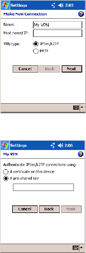
Network Support—Chapter 4
155700 Series Color Mobile Computer User’s Manual
2In Name, enter a name for the connection, such as a company’s name.
In Host name/ IP, enter the VPN server name or IP address.
Next to VPN type, select the type of authentication to use with your
device: “IPSec/L2TP” or “PPTP.” If you are not sure which option to
choose, ask your network administrator. Tap Next to continue.
3Select the type of authentication. If you select A pre-shared key,enter
the key provided by your network administrator.
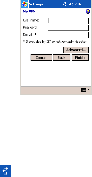
Network SupportChapter —4
156 700 Series Color Mobile Computer User’s Manual
4Enter your user name, password, and domain name as provided by your
ISP or network administrator. If a domain name was not provided, try
the connection without entering a domain name.
5You should not need to change any Advanced settings. Instances where
to change advanced settings include the server to which you are con-
necting does not use dynamically-assigned addresses, and you need to
enter your TCP/IP settings; or to change server DNS or WINS settings.
To change advanced settings, tap Advanced.Otherwise,tapFinish.In-
sert necessary equipment, such as a network (Ethernet) card, into the
device, and use a desired program to automatically begin connecting.
Ending a Connection
When connected via modem or VPN, tap the Connectivity icon on the
navigation bar, and then select Disconnect. When connected via cable or
cradle, detach your device. When connected via Infrared, move the device
away from the other computer or device. When connected via a wireless
network, switch off the connection.
Management
Use the following tool and information to configure and manage your net-
work. You can also contact your Intermec representative for support.
SmartSystemstFoundation Console (www.intermec.com/SmartSystems)
This tool, available as a free download from Intermec, includes a manage-
ment console that provides a default method to configure and manage In-
termec devices “out-of-the-box,” without the purchase of additional soft-
ware licenses. This is for anyone who must configure and deploy multiple
devices or manage multiple licenses.
Use the Intermec Settings applet to gather, view, and update device config-
uration settings within the SmartSystems Foundation. Information about

Network Support—Chapter 4
157700 Series Color Mobile Computer User’s Manual
the settings you can configure with the Intermec Settings applet is in the
Intermec Computer Command Reference Manual (P/N: 073529) available
online at www.intermec.com.
Information about the SmartSystems Foundation is available as an online
help within the SmartSystems Console application. Select SmartSystems >
Help in the console to access the manual.
See the Data Collection Resource Kit in the IDL for information about
data collection functions. The IDL is available as a download from the In-
termec web site at www.intermec.com/idl. Contact your Intermec repre-
sentative for more information.
Tap Start >Settings >theSystem tab>theIntermec Settings icon to ac-
cess the applet, then tap to expand the SmartSystems Information option.
SNMP Configuration on the Mobile Computer
In short, SNMP is an application-layer protocol that facilitates the ex-
change of management information between network devices. The 700
Color Computer is such an SNMP-enabled device. Use SNMP to control
and configure the 700 Color anywhere on an SNMP-enabled network.
The 700 Color supports four proprietary Management Information Bases
(MIBs) and Intermec provides SNMP support for MIB-II through seven
read-only MIB-II (RFC1213-MIB) Object Identifiers (OIDs).
Note: You can only query these seven OIDs through an SNMP manage-
ment station.
Management Information Base
The Management Information Base is a database that contains information
about the elements to be managed. The information identifies the manage-
ment element and specifies its type and access mode (Read-Only, Read-
Write). MIBs are written in ASN.1 (Abstract Syntax Notation.1) — a ma-
chine independent data definition language. Note: Elements to be managed
are represented by objects. The MIB is a structured collection of such objects.

Network SupportChapter —4
158 700 Series Color Mobile Computer User’s Manual
You will find the following MIB files either in the 700 Color Management
Tools or on the web via www.intermec.com:
SINTERMEC.MIB
Defines the root of the Intermec MIB tree.
SITCADC.MIB
Defines objects for Automated Data Collection (ADC), such as bar
code symbologies.
SITCSNMP.MIB
Defines objects for Intermec SNMP parameters and security methods,
such as an SNMP security IP address.
SITCTERMINAL.MIB
Defines objects for 700 Color parameters, such as key clicks.
Object Identifiers
Each object has a unique identifier called an OID, which consist of a se-
quence of integer values represented in dot notation. Objects are stored in
a tree structure and OIDs are assigned based on the position of the object
in the tree. For example, the internet OID is equal to 1.3.6.1. Seven MIB
OIDs are shown in the following table:
MIB-II Item OID Group or Table Description
ifNumber 1.3.6.1.2.1.2.1.0 Interfaces Group Indicates the number of adapters
present in the system. For the 700
Color Computer, if one adapter is
present in the system, then ifNum-
ber =1andifIndex=1.
ifIndex 1.3.6.1.2.1.2.2.1.1.ifIndex Interfaces Table (ifTable) A unique value for each interface.
The value ranges between 1 and the
value of ifNumber.
ifDescr 1.3.6.1.2.1.2.2.1.2.ifIndex Interfaces Table (ifTable) A textual string containing informa-
tion about the interface.
ifType 1.3.6.1.2.1.2.2.1.3.ifIndex Interfaces Table (ifTable) An integer containing information
about the type of the interface. It is
equal to 1 for Other.
ipAdEntAddr 1.3.6.1.2.1.4.20.1.1.IpAddress IP address Table
(ipAddrTable)
The IP address to which this entry’s
addressing information pertains
(same as 700 IP address), where IP
Address is the valid non-zero IP ad-
dress of the 700 Color Computer.
ipAdEntIfIndex 1.3.6.1.2.1.4.20.1.2.IpAddress IP address Table
(ipAddrTable)
The index value that uniquely iden-
tifies the interface to which this
entry is applicable (same as ifIndex).
ipAdEntNetMask 1.3.6.1.2.1.4.20.1.3.IpAddress IP address Table
(ipAddrTable)
Subnet mask associated with the IP
address of this entry (Subnet Mask).
Network Support—Chapter 4
159700 Series Color Mobile Computer User’s Manual
Configuring with SNMP
The community string allows an SNMP manager to manage the 700 Col-
or Computer with a specified privilege level. The default read-only com-
munity string is “public” and “private” is the default read/write communi-
ty string. See the specific configuration parameter to find its OID.
To configure using SNMP, configure 700 Color Computers for RF or
Ethernet communications. Determine the OID (Object Identifier) for the
parameter to be changed. The Intermec base OID is 1.3.6.1.4.1.1963.
Use your SNMP management station to get and set variables that are de-
fined in the Intermec MIBs. You can set the traps, identification, or secu-
rity configuration parameters for SNMP.
Network SupportChapter —4
160 700 Series Color Mobile Computer User’s Manual

161700 Series Color Mobile Computer User’s Manual
Printer Support
5
The 700 Series Color Mobile Computer works with the following printers
from Intermec. Contact an Intermec representative for information about
these printers.
S6808
A 4-inch belt-mount printer.
S6820
A full-page, 80-column printer.
S782T
A 2-inch workboard printer.
SPB20
A 2-inch belt-mount printer with a Bluetooth compatible module from
Socket Communications.
SPB42
A 4-inch wireless portable receipt printer with a Bluetooth compatible
module from Socket Communications.
Note: “700 Color” pertains to 740, 741, 750, 751, 760, and 761 Com-
puters unless otherwise noted.
Printer SupportChapter —5
162 700 Series Color Mobile Computer User’s Manual
Printing ASCII
These methods for printing using Pocket PC at this time is as follows:
SAdd port drivers to print ASCII directly to the port.
SUse LinePrinter ActiveX Control from the Printing Resource Kit via the
Intermec Developer Library (IDL) available as a download from the In-
termec webs site at www.intermec.com/idl.Contact your Intermec rep-
resentative for more information.
SVia wireless printing - see the Bluetooth Resource Kit User’s Guide for more
information.
Directly to a Port
Printing directly to the port sends RAW data to the printer. The format of
this data depends upon your application and the printer capabilities.
You must understand the printer commands available for your specific
printer. Generally, applications just send raw ASCII text to the printer.
Since you are sending data to the printer from your application directly to
the port you are in complete control of the printers operations. This allows
youtodolineprinting(print one line at a time) rather than the page for-
mat printing offered by the GDI approach. It is also much faster since data
does not have to be converted from one graphics format to the other (dis-
play to printer). Most Intermec®printers use Epson Escape Sequences to
control print format operations.
These commands are available in documentation you receive with your
printers or from technical support. Win32 APIs are required to print di-
rectly to the port.
Directly to a Generic Serial Port
To print directly to a generic serial port printer (non-Intermec printers):
SUse CreateFile() to open ports — COM1 can open on most devices.
SUse WriteFile() to send data directly to the printer.
SUse CloseHandle() when you are finished printing to close the port.
IrDA Printer Driver
IrDA printing is only available on the certain devices and is supported di-
rectly by the Windows CE load via the IrSock API provided by the Micro-
soft Win32 API without need for additional drivers. Intermec 6804, 6805,
6806, 6808 and 6820 and other IrDA printers are supported.
Printer Support—Chapter 5
163700 Series Color Mobile Computer User’s Manual
NPCP Printer Driver
The NPCP printer communications driver (NPCPPORT.DLL) is a
Stream Device Driver built into the operating system. The driver supports
only NPCP communications to and from the 6820 and 4820 printers over
a selected serial port.
All applications use WIN32 API functions to access drivers. Applications
easily implement basic operations through the CreateFile(), WriteFile(),
ReadFile(), DeviceIOControl(), and CloseHandle() Win32 APIs.
DeviceIOControl() functions are used to do most upgrade printer mod-
ules, printer diagnostics, and get printer configurations.
About NPCP
NPCP (Norand®Portable Communications Protocol) is a proprietary
protocol that provides session, network, and datalink services for Intermec
mobile computers in the Intermec LAN environment used with printers
and data communications.
NPCP Driver Installation and Removal
Use LPT9: for the NPCP printer device and COM1 for the last parame-
ter. COM1 is the connection available via the 700 Color Computer.
Applications use the RegisterDevice() function to install the driver.
DeregisterDevice() uninstalls the device driver and frees memory space
when the driver is not required. Use the HANDLE returned by
RegisterDevice() as the parameter to DeregisterDevice().
Use the RegisterDevice() function call as demonstrated below. Specify the
full path name to the driver starting at the root for the RegisterDevice()
function to work properly. The last parameter to RegisterDevice() is a
DWORD that represents the name of the port for the NPCP stream
driver to use. Build this parameter on the stack if it is not to be paged out
during the call. The first parameter “LPT” (Device Name) and the second
parameter “9’ (index), indicate the name of the registered device, such as
LPT9. This is used in the CreateFile() function call.
Install()
{HANDLE hDevice;
TCHAR port[6];
port[0] = TCHAR(‘C’);
port[1] = TCHAR(‘O’);
port[2] = TCHAR(‘M’);
port[3] = TCHAR(‘1’);
port[4] = TCHAR(‘:’);
port[5] = TCHAR(0);
hDevice = RegisterDevice ( (TEXT(”LPT”), 9,
TEXT(“\\STORAGE CARD\\WINDOWS\\NPCPPORT.dll”), (DWORD)port);
}
Printer SupportChapter —5
164 700 Series Color Mobile Computer User’s Manual
Opening the NPCP Driver
The application opens the NPCP driver by using the CreateFile()
function. The call can be implemented as follows. The first parameter
“LPT9:”mustreflectthedevicenameandindexusedinthe
RegisterDevice() function call and will fail for any of the following reasons:
hFile = CreateFile(_T(”LPT9:”), GENERIC_WRITE |
GENERIC_READ, 0, NULL, OPEN_ALWAYS, FILE_ATTRIBUTE_NORMAL,
NULL);
SThe port associated with the device during RegisterDevice() is in use.
SThe NPCP device is already open.
SThe share mode is not set to zero. The device cannot be shared.
SAccess permissions are not set to GENERIC_WRITE |
GENERIC_READ. Both modes must be specified.
Closing the NPCP Driver
Using the CloseHandle() (hFile) function closes the NPCP driver. Where
hFile is the handle returned by the CreateFile() function call.
STRUE = the device is successfully closed.
SFALSE = an attempt to close NULL HANDLE or already closed device.
Reading from the NPCP Driver
Reading of the NPCP printers is not supported since all responses from
the printer are the result of commands sent to the printer.
DeviceIoControl() functions are provided where data is to be received
from the printer.
Writing to the NPCP Driver
All Print data can be sent to the printer using the WriteFile() function.
The print data written to the driver must contain the proper printer
commands for formatting. If the function returns FALSE, the NPCP error
may be retrieved using IOCTL_NPCP_ERROR. See the description on
the next page.
NPCP Driver I/O Controls
An application uses the DeviceIoControl() function to specify an printer
operation to be performed. Certain I/O controls are required to bind and
close communication sessions with the printer, and must be completed
before any other commands to the driver can execute properly.
The function returns TRUE to indicate the device successfully completed
its specified I/O control operation, otherwise it returns FALSE. The
following I/O control codes are defined:
Printer Support—Chapter 5
165700 Series Color Mobile Computer User’s Manual
#define IOCTL_NPCP_CANCEL
CTL_CODE(FILE_DEVICE_SERIAL_PORT,0x400,METHOD_BUFFERED,FILE_ANY_ACCESS)
#define IOCTL_NPCP_BIND
CTL_CODE(FILE_DEVICE_SERIAL_PORT,0x401,METHOD_BUFFERED,FILE_ANY_ACCESS)
#define IOCTL_NPCP_CLOSE
CTL_CODE(FILE_DEVICE_SERIAL_PORT,0x402,METHOD_BUFFERED,FILE_ANY_ACCESS)
#define IOCTL_NPCP_ERROR
CTL_CODE(FILE_DEVICE_SERIAL_PORT,0x403,METHOD_BUFFERED,FILE_ANY_ACCESS)
#define IOCTL_NPCP_FLUSH
CTL_CODE(FILE_DEVICE_SERIAL_PORT,0x404,METHOD_BUFFERED,FILE_ANY_ACCESS)
#define IOCTL_NPCP_IOCTL
CTL_CODE(FILE_DEVICE_SERIAL_PORT,0x405,METHOD_BUFFERED,FILE_ANY_ACCESS)
#define IOCTL_NPCP_PRTVER
CTL_CODE(FILE_DEVICE_SERIAL_PORT,0x406,METHOD_BUFFERED,FILE_ANY_ACCESS)
SIOCTL_NPCP_CANCEL
This cancels all printing at the printer. It flushes the printer buffers and
reinitializes the printer to its default state. No parameters are required.
SIOCTL_NPCP_BIND
This command is required before any data is sent or received by the
printer. Once the driver is opened, the application must bind the com-
munications session with the printer before any data can be sent or re-
ceived by the printer. If an error occurs during the bind, the application
may use IOCTL_NPCP_ERROR to get the current extended error
code. No parameters are required.
SIOCTL_NPCP_CLOSE
This command closes the current session with the printer. This function
always returns TRUE. No parameters are required.
SIOCTL_NPCP_ERROR
This command returns the extended NPCP error code in PL/N format.
The word returned will contain the PL/N compatible error code in the
low byte and completion flags in the high byte. If the frame that re-
turned an error was not received correctly by the printer the
FRAME_NOT_ACKED bit will be set in the high byte. This operation
always returns TRUE. An output buffer of at least 2 bytes is required.
See “NPCP Error Codes” on page 166.
SIOCTL_NPCP_FLUSH
This command allows the application to poll the printer for errors while
the report is completing the print process at the printer. If an error oc-
curs during the polling process, the operation will return FALSE and
the application can get the extended error code by using
IOCTL_NPCP_ERROR. No parameters are required.
NPCP Printer Communications
All NPCP printer communications should be based on the following flow:
1Use CreateFile(); to open the printer driver.
2Use IOCTL_NPCP_BIND to bind a session with the printer;
IOCTL_NPCP_ERROR to check for errors on the bind to ensure suc-
cess; and IOCTL_NPCP_CANCEL to cancel outstanding print jobs.
Printer SupportChapter —5
166 700 Series Color Mobile Computer User’s Manual
3Use IOCTL_NPCP_FLUSH to poll the printer to free up printer buff-
er resources. Use IOCTL_NPCP_FLUSH to poll the printer’s status. If
an error is reported by the IOCTL, then use IOCTL_NPCP_ERROR
to get the error and determine the correct recovery procedure.
4Use WriteFile(); to write data to the printer. Check for errors and that
alldatawerewritten.UseIOCTL_NPCP_ERRORtogettheextended
error. If the error is critical in nature, use IOCTL_NPCP_CLOSE, fol-
lowed by CloseFile(), to end the communications session. Start a new
session, beginning with step 1 to ensure proper printing. For noncritical
errors display the error and retry the operation.
5After all data is sent to the printer, ensure that the printer continues to
print the report properly by polling the printer’s status. Use
IOCTL_NPCP_FLUSH to poll the printer’s status. If an error is re-
ported by the IOCTL, then use IOCTL_NPCP_ERROR to get the
error and determine the correct recovery procedure.
Sample Code
See sample code in the “\700C Dev Tools\Installable Drivers\Port
Drivers\Npcp\NPCPPrint\” directory for more details on printing, printer
communications and error code handling.
NPCP Error Codes
Call the IOCTL_NPCP_ERROR I/O control to receive PL/N compatible
error codes. Applications must decide how to act on the data returned.
// Definition of NPCP communications Errors and Printer Errors
#define PNRDY (BYTE)102 // link not ready error
#define RXTMO (BYTE)104 // link no receive error
#define TXTMO (BYTE)106 // link no transmit error
#define BADADR (BYTE)111 // frame address error
#define GAPERR (BYTE)112 // link gap error (timeout) in receive data
#define LSRPE (BYTE)113 // frame parity error on length field
#define IFTS (BYTE)120 // session layer - invalid frame this state
#define NS_NE_VR (BYTE)121 // session layer sequence error
#define NR_NE_VS (BYTE)122 // session layer sequence error
#define MAC_CRCERR (BYTE)124 // MAC CRC error
#define RLENERR (BYTE)123 // MAC too much data received
#define FRMERR (BYTE)200 // Frame Reject
#define FRMERR_IF (BYTE)201 // Frame Reject - Invalid Frame
#define FRMERR_NR (BYTE)202 // Frame Reject - NR Mismatch
#define FRMERR_NS (BYTE)203 // Frame Reject - NS Mismatch
#define NDMERR (BYTE)204 // Normal Disconnect mode error
#define BINDERR (BYTE)210 // bind error
#define IPLDUR (BYTE)221 // invalid presentation layer response
#define HEADJAM (BYTE)222 // printer head jam
#define PAPEROUT (BYTE)223 // printer paper out
#define LOWVOLTS (BYTE)224 // printer low voltage
#define HIVOLTS (BYTE)225 // printer over voltage
#define LOWBAT (BYTE)226 // printer low battery
#define COVEROFF (BYTE)227 // printer cover off error
#define HEADFAULT (BYTE)228 // printer head short or driver short error
#define PFFAULT (BYTE)229 // paper feed motor fault.
#define FRAME_NOT_ACKED 0x8000 // frame was not received by printer and need
to be resent.
Printer Support—Chapter 5
167700 Series Color Mobile Computer User’s Manual
O’Neil Printer Driver
The DTR printer communications driver is a Stream Device Driver
named ONEIL.DLL.
All applications use WIN32 API functions to access drivers. Applications
easily implement basic operations using the CreateFile(), WriteFile(),
DeviceIOControl() and CloseHandle() Win32 APIs.
The driver supports communications to 6804DM, 6804T, 6805A, 6806,
6808, 681T, PB20, and PB42 printers over a selected serial port.
DTR Driver Installation and Removal
Your application must use the RegisterDevice() function to install the
ONEIL.DDL device driver. Use “DTR” for the Device Name parameter,
“1” for the Device Driver index parameter, and any of these strings for the
last parameter:
SNULL (==0) Defaults to COM1 @ 9600
S“COM1” only COM port specified defaults to 9600
S“COM1:9600” sets to COM port and specified bit rate
S“COM1:19200” sets to COM port and specified bit rate
Use the HANDLE returned by RegisterDevice() as the parameter to
DeregisterDevice(). The correct usage of the RegisterDevice() function call
is shown below. You may use DeregisterDevice() to uninstall the driver.
Install()
{
HANDLE hDevice;
TCHAR port[6];
port[0] = TCHAR(‘C’);
port[1] = TCHAR(‘O’);
port[2] = TCHAR(‘M’);
port[3] = TCHAR(‘1’);
port[4] = TCHAR(‘:’);
port[5] = TCHAR(0);
hDevice = RegisterDevice ( (TEXT(”DTR”), 1, TEXT(”\\WINDOWS\\ONEIL.DLL”),
(DWORD)port);
}
Opening the DTR Driver
The application opens the DTR driver by using the CreateFile() function.
The call can be implemented as follows:
hFile = CreateFile(_T(”DTR1:”), GENERIC_WRITE, 0, NULL,
OPEN_ALWAYS, FILE_ATTRIBUTE_NORMAL, NULL);
The first parameter “DTR1:” must reflect the device name and index used
in the RegisterDevice() function call.
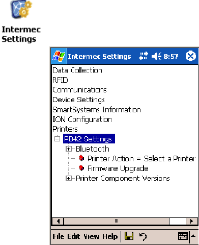
Printer SupportChapter —5
168 700 Series Color Mobile Computer User’s Manual
The function call will fail for any of the following reasons:
SPort associated with device during RegisterDevice() is currently in use.
SThe DTR device is already open.
SThe share mode is not set to zero. The device cannot be shared.
SAccess permissions are not set to GENERIC_WRITE.
Closing the DTR Driver
Using the CloseHandle() (hFile) function closes the DTR driver. Where
hFile is the handle returned by the CreateFile() function call.
STRUE indicates the device is successfully closed.
SFALSE indicates an attempt to close a NULL HANDLE or an already
closed device.
Writing to the DTR Driver
Use the WriteFile() function to send all print data to the printer. The data
must contain the proper formatting printer commands.
DTR Printer Communications
All DTR printer communications should be based on the following flow:
1Use CreateFile() to open the printer driver.
2Use WriteFile() to write your data to the printer. Check for errors and
that all data were written.
3Use CloseHandle() to close the driver.
Configuring PB42 Printers Via Intermec Settings
Tap Start >Settings >theSystem tab>theIntermec Settings icon to ac-
cess the applet. Tap (+) to expand the Printers option, then tap (+) to ex-
pand the PB42 Settings option and make your adjustments.

169700 Series Color Mobile Computer User’s Manual
Scanner Support
6
The 700 Series Color Mobile Computer is available with imaging or laser
scanning technologies, including the following:
APS Linear Imager:(standard for 730 Computers)
— includes the EV10 Scan Engine
Reads 1D symbologies and PDF417 bar codes. Linear imag-
ing using Vista Scanning technology reads low-contrast bar
codes, laminated bar codes, and bar codes displayed on CRT
or TRT displays. This imaging uses harmless LEDs for illu-
mination and does not require any warning labels. Vista Scan-
ning is more reliable than lasers as it is a completely solid state
with no moving parts or oscillating mirrors.
2D Imager:(not supported on 730 Computers)
— includes the IT4000 Scan Engine
This decodes several stacked 1D and 2D symbologies, includ-
ing PDF417, Data Matrix, and MaxiCode without “paint-
ing.” It can also read 1D codes from any orientation, for ex-
ample the scan beam does not need to align perpendicular to
the symbol to read it. Photography is a secondary application;
the lens in the device favors bar code reading. Photos are
640x480, 256 gray-scale.
1D Laser Scanner:(not supported on 730 Computers)
— includes the SE900, SE900HS, SE900-S6, and
SE900HS-S6 scan engines
Traditional laser scanner that decodes 1D bar codes.
PDF417 Laser Scanner:(not supported on
730 Computers)
Higher speed laser scanner that can read PDF417 labels by
“painting” the label.
EL10 Laser Scanner An EXCELeratetbar code laser scan engine, based on the
Micro Electro Mechanical System (MEMS) technology, that
is significantly faster, lighter, and more efficient than tradi-
tional laser scanners.

Scanner SupportChapter —6
170 700 Series Color Mobile Computer User’s Manual
A 700 Color ImageDemo application demonstrates the more common fea-
tures of the 700 Color Computer imager. See the ImageDemo User’s Guide
for information.
Note: “700 Color” pertains to 740, 741, 750, 751, 760, and 761 Com-
puters unless otherwise noted.
Scanner Control and Data Transfer
Note: To use the methods described below, enable Data Collection func-
tionality on the 700 Computer using the bootloader configuration menu.
The Data Server and associated software provide several ways to manipu-
late scanner control and data transfer between the scanner subsystem and
user applications:
SAutomatic Data Collection COM Interfaces:
These COM interfaces allow user applications to receive bar code data,
and configure and control the bar code reader engine.
SITCAxBarCodeReaderControl functions:
These ActiveX controls allow user applications to collect bar code data
from the scanner, to configure the scanner, and to configure audio and
visual notification when data arrives.
SITCAxReaderCommand functions:
Use these ActiveX controls to modify and retrieve configuration infor-
mation using the reader interface commands.
SScanning EasySet bar code labels:
You can use the EasySetRbar code creation software from Intermec to
print configuration labels. Scan the labels to change the scanner configu-
ration and data transfer settings.
Use the Intermec EasySet software to print configuration labels you can
scan to change your configuration settings. For more information, see
the EasySet online help. EasySet is available from the Intermec Data
Capture web site.
For more information, see the Data Collection Resource Kit in the Inter-
mec Developer Library (IDL), which is available as a download from the
Intermec web site at www.intermec.com/idl. Contact your Intermec repre-
sentative for more information.
Data Collection Configuration
You can configure scanner and reader settings for the 700 Color Comput-
er via the Intermec Settings applet. From the 700 Color Computer, tap
Start >Settings >theSystem tab>theIntermec Settings icon. See the
Intermec Computer Command Reference Manual (P/N: 073529) for infor-
mation about the settings you can configure with this applet. This online
manual is available from the Intermec web site at www.intermec.com.

6 Scanner Support—Chapter
171700 Series Color Mobile Computer User’s Manual
Internal Scanners
The Intermec Internal Scanner feature allows Automatic Data Collection
(ADC) by accepting data from the COM1 port and wedging it into the
keyboard interface. You can enable or disable this feature from the Today
screen on the 700 Color Computer.
Before you configure your internal scanner, adjust its settings using the
Intermec Settings applet. Information about the settings you can configure
with this applet is described in the Intermec Computer Command Reference
Manual. The online manual is available from the Intermec web site at
www.intermec.com.
1From the 700 Color Computer, tap Start >Settings >theSystem tab >
the Intermec Settings icon.
2Tap the Data Collection option, then tap (+) to expand Internal
Scanner.This sample screen is for the IT4000 scan engine.

Scanner SupportChapter —6
172 700 Series Color Mobile Computer User’s Manual
Scanner and Imager Settings
Depending on what is selected as the scanner model, image settings, de-
code security, scanner settings, and virtual wedge are configured from the
Intermec Settings applet. See the the Intermec Computer Command Refer-
ence Manual, available from the Intermec web site at www.intermec.com,
for more information about each enabled option.
Internal Scanner Supported Symbologies
Symbologies EL10 EV10 IT4000 SE900 SE900HS SE900-S6 SE900HS-S6
Code39 XXXXX X X
UPC/EAN XXXXX X X
Code 128 XXXXX X X
Interleaved 2 of 5 XXXXX X X
Code 93 XXXXX X X
Codabar XXXXX X X
Code 2 of 5 XXXXX X X
MSI XXXXX X X
Plessey XXXXX X X
Code 11 XXXXX X X
Matrix 2 of 5 XXXXX X X
Telepen XXXXX X X
PDF417 XXXXX X X
Micro PDF417 XXXXX X X
MaxiCode X
Data Matrix X
QR Code X
RSS 14 XXXXXAvailable in
f/w Sxxp304
Available in
f/w Sxxp304
RSS Limited XXXXXAvailablein
f/w Sxxp304
Available in
f/w Sxxp304
RSS Expanded XXXXXAvailable in
f/w Sxxp304
Available in
f/w Sxxp304
Codablock A XXXXX X X
Codablock F XXXXX X X
UCC Composite X
TLC 39 XXXXX X X

6 Scanner Support—Chapter
173700 Series Color Mobile Computer User’s Manual
Reading Distances
Typical reading distances are done in an office environment using office
lights (4 lux). Minimum distances are measured in the dark (0 lux). Both
reading distances are provided in respective scan engine integration guides.
Contact your Intermec representative for more information.
Below are minimum standard reading distances for 700 Color Computers
built with integrated scan engines. When correctly mounted, an exit win-
dow reduces reading distances by about 4% for all scan engines, with the
exception of the EL10 with its reading distances reduced by about 25%.
EA10 Minimum Reading Distances with 0.04” Setbacks
Symbology Density Minimum Distance Maximum Distance
Code 39 0.125 mm/ 5 mil
0.15 mm/ 6 mil
0.20 mm/ 8 mil
0.25 mm/ 10 mil
0.30 mm/ 12 mil
0.5 mm/ 20 mil
1.0 mm/ 40 mil
8.03 cm/ 3.16”
7.39 cm/ 2.91”
5.49 cm/ 2.16”
3.96 cm/ 1.56”
3.71 cm/ 1.46”
4.98 cm/ 1.96”
3.71 cm/ 1.46”
11.84 cm/ 4.66”
14.38 cm/ 5.66”
19.46 cm/ 7.66”
24.03 cm/ 9.46”
25.81 cm/ 10.16”
35.97 cm/ 14.26”
50.95 cm/ 20.06”
UPC/EAN 4.98 cm/ 1.96” 29.87 cm/ 11.76”
PDF417 0.168 mm/ 6.6 mil
0.254 mm/ 10 mil
0.381 mm/ 15 mil
7.26 cm/ 2.86”
4.47 cm/ 1.76”
10.06 cm/ 3.96”
12.85 cm/ 5.06”
20.98 cm/ 8.26”
28.35 cm/ 11.16”
Data Matrix 0.254 mm/ 10 mil
0.381 mm/ 15 mil
0.508 mm/ 20 mil
6.50 cm/ 2.56”
5.99 cm/ 2.36”
4.98 cm/ 1.96”
17.93 cm/ 7.06”
27.84 cm/ 10.96”
32.92 cm/ 12.96”
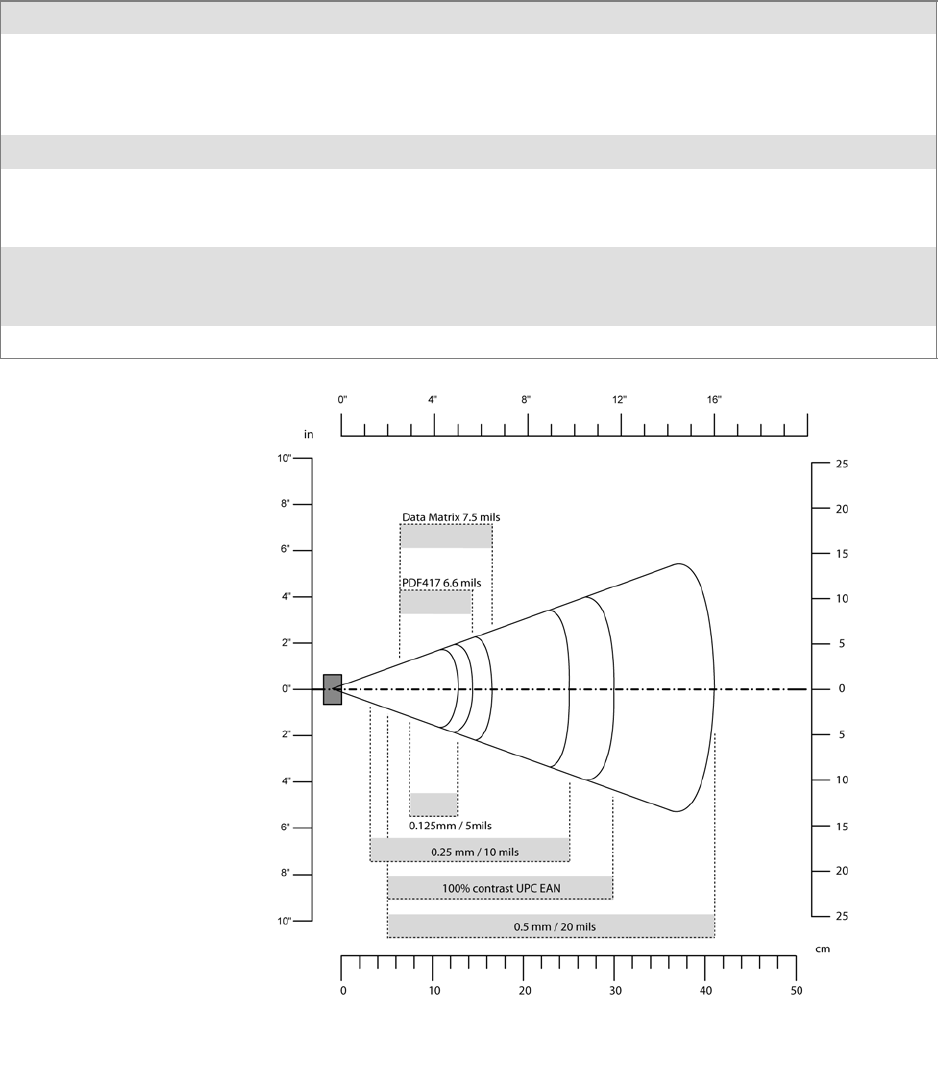
Scanner SupportChapter —6
174 700 Series Color Mobile Computer User’s Manual
EA11 Standard Minimum Reading Distances with 0.04” Setbacks
Symbology Density Minimum Distance Maximum Distance
Code 39 0.125 mm/ 5 mil
0.20 mm/ 8 mil
0.25 mm/ 10 mil
0.5 mm/ 20 mil
7.26 cm/ 2.86”
3.96 cm/ 1.56”
3.45 cm/ 1.36”
4.98 cm/ 1.96”
12.09 cm/ 4.76”
20.98 cm/ 8.26”
25.04 cm/ 9.86”
40.28 cm/ 15.86”
UPC/EAN 0.33 mm/ 13 mil 4.98 cm/ 1.96” 29.62 cm/ 11.66”
Data Matrix 0.191 mm/ 7.5 mil
0.254 mm/ 10 mil
0.381 mm/ 15 mil
3.71 cm/ 2.46”
5.98 cm/ 1.96”
*
16.41 cm/ 6.46”
20.73 cm/ 8.16”
27.58 cm/ 10.86”
PDF417 0.168 mm/ 6.6 mil
0.254 mm/ 10 mil
0.381 mm/ 15 mil
6.25 cm/ 2.46”
4.47 cm/ 1.76”
4.98 cm/ 1.96”
13.87 cm/ 5.46”
21.74 cm/ 8.56”
33.43 cm/ 13.16”
* Minimum distance depends on symbology length and scan angle.
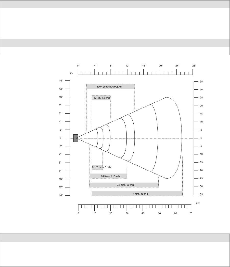
6 Scanner Support—Chapter
175700 Series Color Mobile Computer User’s Manual
EL10 Minimum Guaranteed Reading Distances with 0.25” Setbacks
Symbology Density Minimum Distance Maximum Distance
Code 39 0.1 mm/ 4 mil
0.125 mm/ 5 mil
0.25 mm/ 10 mil
0.5 mm/ 20 mil
1 mm/ 40 mil
8.51 cm/ 3.35”
7.75 cm/ 3.05”
6.99 cm/ 2.75”
6.48 cm/ 2.55”
7.75 cm/ 3.05”
12.30 cm/ 4.45”
14.35 cm/ 5.65”
29.34 cm/ 11.55”
50.17 cm/ 19.75”
63.37 cm/ 24.95”
UPC/EAN 0.33 mm/ 13 mil 5.46 cm/ 2.15” 34.42 cm/ 13.55”
PDF417 0.17 mm/ 6.6 mil 7.75 cm/ 3.05” 19.43 cm/ 7.65”
EL11 Minimum Reading Distances with 0.04” Setbacks
Symbology Density Minimum Distance Maximum Distance
0.1 mm/ 4 mil
0.125 mm/ 5 mil
0.33 mm/ 13 mil (EAN)
1 mm/ 40 mil
8.79 cm/ 3.46”
8.28 cm/ 3.26”
5.49 cm/ 2.16”
9.55 cm/ 3.86”
11.84 cm/ 4.66”
14.48 cm/ 5.86”
34.95 cm/ 13.76”
63.91 cm/ 25.16”

Scanner SupportChapter —6
176 700 Series Color Mobile Computer User’s Manual
EV10 Minimum Reading Distances with 0.04” Setbacks
Symbology Bar Code Content Density Minimum Distance Maximum Distance
Code 39 RESO 0.100 MM
R 0.125 MM
0.25
0.5
R1MM
0.1 mm/ 4 mil
0.125 mm/ 5 mil
0.25 mm/ 10 mil
0.5 mm/ 20 mil
1 mm/ 40 mil
10.8 cm/ 4.26”
9.80 cm/ 3.86”
5.99 cm/ 2.36”
3.96 cm/ 1.56”
7.53 cm/ 2.96”
13.87 cm/ 5.46”
16.92 cm/ 6.66”
23.77 cm/ 9.36”
30.89 cm/ 12.16”
39.78 cm/ 15.66”
UPC/EAN 120010010100 0.33 mm/ 13 mil 4.98 cm/ 1.96” 25.81 cm/ 10.16”
PDF417 10 mil
15 mil
0.254 mm/ 10 mil
0.381 mm/ 15 mil
9.80 cm/ 3.86”
7.77 cm/ 3.06”
16.92 cm/ 6.66”
18.95 cm/ 7.46”
2D Area Imager Reading Distances with 0.04” Setbacks
Symbology Density Near Distance Far Distance
MaxiCode 35 mil 4.98 cm/ 1.96” 33.92 cm/ 12.96”
Data Matrix 15 mil 9.30 cm/ 3.66” 16.41 cm/ 6.46”
PDF417 10 mil
8mil
6.6 mil
7.77 cm/ 3.06”
8.28 cm/ 3.26”
11.33 cm/ 4.46”
22.76 cm/ 8.96”
20.22 cm/ 7.96”
15.77 cm/ 6.21”
Code 39 15 mil
10 mil
8mil
5.23 cm/ 2.06”
8.03 cm/ 3.16”
8.79 cm/ 3.46”
29.87 cm/ 11.76”
23.27 cm/ 9.16”
19.20 cm/ 7.56”
UPC 13 mil 6.25 cm/ 2.46” 31.65 cm/ 12.46”
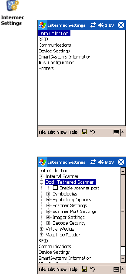
6 Scanner Support—Chapter
177700 Series Color Mobile Computer User’s Manual
Tethered Scanners
The Intermec Tethered Scanner feature allows Automatic Data Collection
(ADC) by accepting data from the COM1 port and wedging it into the
keyboard interface. You can enable or disable this feature from the Today
screen on the 700 Color Computer.
Configuring the Tethered Scanner
Before you configure your tethered scanner, adjust its settings using the
Intermec Settings applet. Information about the settings you can configure
with this applet is described in the Intermec Computer Command Reference
Manual. The online manual is available from the Intermec web site at
www.intermec.com.
1Connect your tethered scanner to the tethered scanner port.
2From the 700 Color Computer, tap Start >Settings >theSystem tab >
the Intermec Settings icon.
3Tap Data Collection, then tap (+) to expand Dock Tethered Scanner.

Scanner SupportChapter —6
178 700 Series Color Mobile Computer User’s Manual
4Tap (+) to expand Scanner Settings,tapScanner model,thenenterthe
applicable scanner, such as “1551E” or “1553.”
5Make sure a scanner is properly connected to your 700 Computer, tap
to check Enable scanner port,thentapFile >Save Settings from the
bottom of the screen. These changes take several moments to reset.
1551E or 1553 Selected for Scanner Model
When “1551E” or “1553” is selected from the Scanner model option (see
step 4 above), and the port state is already enabled (see step 5),theprocess
will take several moments to reset. When 1551E or 1553 is successfully
connected during this step, the unit will emit some beeps. Here, the termi-
nal is initializing the scanner at 9600 for the baud rate, 7 data bits, even
parity, and 2 stop bits and synchronizing the terminal’s configuration with
the attached scanner.
With “1551E” or “1553” selected, Symbologies, Symbology Options,
Hardware Trigger, and Scanner Port settings are configured from the In-
termec Settings applet. See the the Intermec Computer Command Reference

6 Scanner Support—Chapter
179700 Series Color Mobile Computer User’s Manual
Manual, available from the Intermec web site at www.intermec.com, for
more information about each enabled option.
ASCII Selected for Scanner Model
To send data coming into the 700 Color Computer through the COM1
port from an external input device, as keyboard data to an application on
the desktop, do the following:
1Enter “ASCII” as the Scanner model option.
2Tap to check Enable scanner port.
3Tap File >Save Settings from the bottom of the screen, or tap Yes
when prompted to refresh the scanner settings.
With “ASCII” selected, Symbology Options, Hardware Trigger, and Scan-
ner Port settings are configured from the Intermec Settings applet. See the
the Intermec Computer Command Reference Manual, available from the In-
termec web site at www.intermec.com, for more information about each
enabled option.
Note: When selecting either the 1551E or the 1553 Scanner or enabling
the scanner port for these scanners, the 700 Computer tries to communi-
cate with the attached scanner. If the scanner is not powered, if the cable is
not connected properly, the wrong cable is used, or if the scanner firmware
is older than 2.0, and the “Failed to save one or more settings” message
appears, then this step failed.
This process can take time as the terminal is going through a group of
RS-232 settings to communicate with the scanner. After successful com-
municated with the scanner (about eight beeps are generated), it initializes
the scanner with the 700 Computer’s current settings. This process might
generate a series of beeps pending on the firmware version installed in the
scanner. These beeps are suppressed in firmware versions 2.08 or greater.
Troubleshooting the 1551E/1553 Tethered Scanner
Do the following to troubleshoot your 1551E/1553 Tethered Scanner:
1Ensure the correct cable is used for the scanner on the tethered scanner
port. Note the 700 Computer cannot supply power to the scanner.
2Perform a quick test to determine whether the connection is good.
Temporary select the scanner model as “ASCII,” then enable the scan-
ner port state. Go to a command prompt or a notepad and scan a data
label. If a label is wedged into the command prompt or notepad, then
the connection is good.
3If step 2 passes, reset the scanner configurations to their defaults (scan
the Reset Factory Defaults label on the next page) to prevent miscom-
munication, then reenable the scanner port state.
4If step 2 fails, then the firmware installed in the tethered scanner may be
older than version 2.0. Upgrade your scanner firmware.

Scanner SupportChapter —6
180 700 Series Color Mobile Computer User’s Manual
Reset Factory Defaults
Scan the EasySet software bar code label “Reset Factory Default” to restore
all of your scanner’s configurations to their factory defaults. When this
command label is scanned, reinitialize the tethered scanner (such as disable
the scanner port state, then enable it) on the 700 Computer. Otherwise,
the online configuration and scanning on the 700 Computer are not func-
tional. In general, scan this label only to initially reset the scanner.
Do not scan EasySet command labels to change the following settings:
SSymbologies code mark SCode 128, EAN29 Identifier
SPreamble and Postamble SEnable/Disable symbologies
SSymbology ID transmit option
In some cases, scanning EasySet Command labels cause the current setting
on the user interface to be out of sync with the scanner settings. However,
in some cases, scanning these labels does corrupt scanned data.
The “Open COMx error: 0x00000037” message appears if the COM port
cannot open due to another application using the port. Disable that ap-
plication to free up the COM1 port before you can enable the scanner. “x”
is the COM port number, such as 1, 2, or 3.
Tethered Scanner Supported Symbologies
The user interface may allow configuration of PDF417, Micro PDF417,
RSS, and Codablock bar code symbologies. However, these symbologies
are dependant on what scanner models and firmware versions are in use.
See the following table for a guideline on each supported symbology:
You can use a generic ASCII scanner with the 700 Color Computer.
Pending on the scanner, linear symbologies such as Code39, should de-
code correctly. However, 2D symbologies such as PDF417 may not de-
code correctly.
Symbologies 1551E 1553
Code39 XX
UPC/EAN X X
Code 128 XX
Interleaved 2 of 5 X X
Code 93 XX
Codabar X X
Code 2 of 5 XX
MSI X X
Plessey XX
Code 11 X X
Matrix 2 of 5 XX
Telepen X X

6 Scanner Support—Chapter
181700 Series Color Mobile Computer User’s Manual
15531551ESymbologies
PDF417 Available in 1551 0808 PDF
Micro PDF417 Available in 1551 0808 PDF, Sxxp217_ or later
MaxiCode
Data Matrix
QR Code
RSS 14 F/w version 2.15 or later F/w version 2.15 or later
RSS Limited F/w version 2.15 or later F/w version 2.15 or later
RSS Expanded F/w version 2.15 or later F/w version 2.15 or later
Codablock A Available in 1551 0808 PDF
Codablock F Available in 1551 0808 PDF
UCC Composite
Attached RFID Readers
Note: The 700 Color Computer currently supports only the IP4 Intellitag
Portable RFID Reader, a trigger handle accessory that lets you hold your
700 Color Computer like a reader or scanner. Contact your Intermec rep-
resentative for more information.
Radio frequency identification (RFID) systems evolved as a way to provide
all the benefits of visual scanning systems, while overcoming many of their
limitations. Radio frequency (RF) describes electromagnetic waves in the
10 kHz to 10 GHz range. Electronic identification (ID) systems transfer
data messages from an object to be identified to a data management sys-
tem. RFID systems use radio frequency to transfer data between an item
being tracked and a reader/writer. It is a fast, automatic identification
technology.
More information about RFID and the IP4 Reader are in the following
Intermec publications. PDFs of these publications are available from the
Intermec web site at www.intermec.com.
SBasic Reader Interface Programmer’s Reference Manual
(P/N: 937-000-001)
SIntermec RFID System Manual (P/N: 936-000-001)
SIP4 Handheld Reader Instructions (P/N: 943-002-002)
SIP4 Handheld Reader Manual Supplement (P/N: 933-000-001)
Reading RFID Tags with the Virtual Wedge
The virtual wedge is a Data Collection services feature that enters bar code
and RFID tag data into a software application as if it were typed at the
keypad. This section explains how to configure the 700 Color Computer
to read RFID tags through the virtual wedge. Contact your Intermec rep-
resentative for more information about the virtual wedge.
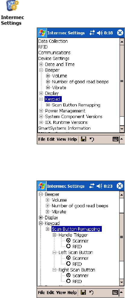
Scanner SupportChapter —6
182 700 Series Color Mobile Computer User’s Manual
Do the following to configure your virtual wedge to do RFID tags.
SConfigure at least one scan button on the 700 Color Computer to trig-
ger RFID (gotothenextparagraph).
SDisable power to Bluetooth (go to page 183 for instructions).
SEnable the IP4 Reader (go to page 184 for instructions).
Use the Intermec Settings applet to configure at least one scan button. In-
formation about the settings you can configure with this applet is de-
scribed in the Intermec Computer Command Reference Manual.Theonline
manual is available from the Intermec web site at www.intermec.com.
1From the 700 Color Computer, tap Start >Settings >theSystem tab >
the Intermec Settings icon > the Device Settings option, then tap (+) to
expand the Keypad option.
2Tap (+) to expand Scan Button Remapping, then tap (+) to expand any
of the Handle Trigger,theLeft Scan Button,ortheRight Scan Button
options. Note that the Handle Trigger option is for the IP4 Reader.

6 Scanner Support—Chapter
183700 Series Color Mobile Computer User’s Manual
3Select RFID to change the trigger from the scanner to RFID, then select
File >Save Settings.
4Go to the next paragraph to disable power to Bluetooth.
5Go to page 184 to enable the IP4 Reader.
Disable Power to Bluetooth
Note: Before you configure your attached IP4 Reader, make sure Blue-
tooth is disabled on your 700 Color Computer.
1Tap Start >Settings >theConnections tab>theBluetooth icon.
2Check whether Off isselected.Ifnot,thencheckOff.Waitmomentari-
ly for Bluetooth to turn off, then click ok to close the Bluetooth applet.
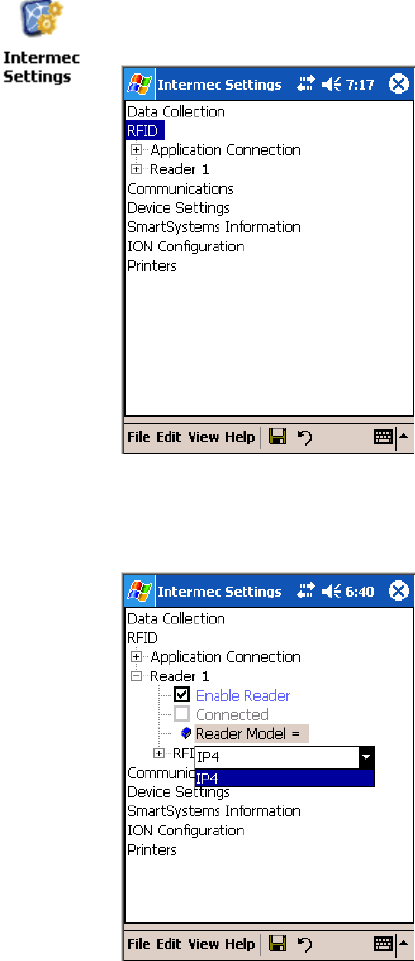
Scanner SupportChapter —6
184 700 Series Color Mobile Computer User’s Manual
Configure the Reader Using Intermec Settings
You should also adjust its settings using the Intermec Settings applet. In-
formation about the settings you can configure with this applet is de-
scribed in the Intermec Computer Command Reference Manual.Theonline
manual is available from the Intermec web site at www.intermec.com.
1Connect your reader to the reader port.
1From the 700 Color Computer, tap Start >Settings >theSystem tab >
the Intermec Settings icon > the RFID option.
2Tap (+) to expand Reader 1 and ensure Reader Model shows “IP4” as
the model of choice. If not, then tap Reader Model, tap its drop-down,
then select “IP4.”

6 Scanner Support—Chapter
185700 Series Color Mobile Computer User’s Manual
3Under the Reader option, check Enable Reader to enable the attached
reader.
Once the IP4 reader is configured using the Intermec Settings applet, ap-
plications can access the IP4 Reader using the Basic Reader Interface (BRI)
protocol on the 700 Color TCP port “2189.”
Scanner SupportChapter —6
186 700 Series Color Mobile Computer User’s Manual

187700 Series Color Mobile Computer User’s Manual
Programming
7
The following programming information pertains to the 700 Series Color
Mobile Computer:
SCreating CAB Files (page 188)
SCustomization and Lockdown (page 202)
SFTP Server (page 203)
SKernel I/O Control Functions (page 210)
SNetwork Selection APIs (page 221)
SNotifications (page 221)
SReboot Functions (page 222)
SRemapping the Keypad (page 223)
Note: “700 Color” pertains to 730, 740, 741, 750, 751, 760, and 761
Computers unless otherwise noted.
ProgrammingChapter —7
188 700 Series Color Mobile Computer User’s Manual
Creating CAB Files
The Windows CE operating system uses a .CAB file to install an applica-
tion on a Windows CE-based device. A .CAB file is composed of multiple
files that are compressed into one file. Compressing multiple files into one
file provides the following benefits:
SAll application files are present.
SA partial installation is prevented.
SThe application can be installed from several sources, such as a desktop
computer or a Web site.
Use the CAB Wizard application (CABWIZ.EXE) to generate a .CAB file
for your application.
Creating Device-Specific CAB Files
Do the following to create a device-specific .CAB file for an application, in
the order provided:
1Create an .INF file with Windows CE-specific modifications (page
188).
2Optional Create a SETUP.DLL file to provide custom control of the
installation process (page 197).
3Use the CAB Wizard to create the .CAB file, using the .INF file, the
optional SETUP.DLL file, and the device-specific application files as
parameters (page 201).
Creating an .INF File
An .INF file specifies information about an application for the CAB Wi-
zard. Below are the sections of an .INF file:
[Version]
This specifies the creator of the file, version, and other relevant informa-
tion.
Required? Yes
SSignature:“signature_name”
“$Windows NT$”
SProvider:“INF_creator”
The company name of the application, such as “Microsoft.”
SCESignature
“$Windows CE$”
Example
[Version]
Signature = “$Windows NT$”
Provider = “Intermec”
CESignature = “$Windows CE$”
Programming—Chapter 7
189700 Series Color Mobile Computer User’s Manual
[CEStrings]
This specifies string substitutions for the application name and the default
installation directory.
Required? Yes
SAppName:app_name
Name of the application. Other instances of %AppName% in the .INF
file are replaced with this string value, such as RP32.
SInstallDir:default_install_dir
Default installation directory on the device. Other instances of %Install-
Dir% in the .INF file are replaced with this string value. Example:
\SDMMC_Disk\%AppName%
Example
[CEStrings]
AppName=“Game Pack”
InstallDir=%CE1%\%AppName%
[Strings]
This section is optional and defines one or more string keys. A string key
represents a string of printable characters.
Required? No
Sstring_key:value
String consisting of letters, digits, or other printable characters. Enclose
value in double quotation marks ““”” if corresponding string key is used
in an item requiring double quotation marks. No string_keys is okay.
Example
[Strings]
reg_path = Software\Intermec\My Test App
[CEDevice]
Describes the platform for the targeted application. All keys are optional.
If a key is nonexistent or has no data, Windows CE does not perform any
checking except the UnsupportedPlatforms.IftheUnsupportedPlatforms key
exists but no data, the previous value is not overridden.
Required? Yes
SProcessorType :processor_type
The value that is returned by SYSTEMINFO.dwProcessorType.For
example, the value for the ARM CPU is 2577
SUnsupportedPlatforms:platform_family_name
This lists known unsupported platform family names. If the name
specified in the [CEDevice.xxx] section is different from that in the
[CEDevice] section, both platform_family_name values are unsupported
for the microprocessor specified by xxx. That is, the list of unsupported
platform family names is appended to the previous list of unsupported
names. Application Manager will not display the application for an
unsupported platform. Also, a user will be warned during the setup
process if the .CAB file is copied to an unsupported device.

ProgrammingChapter —7
190 700 Series Color Mobile Computer User’s Manual
Example
[CEDevice]
UnsupportedPlatforms = pltfrm1 ; pltfrm1 is unsupported
[CEDevice.SH3]
UnsupportedPlatforms = ; pltfrm1 is still unsupported
SVersionMin:minor_version
Numeric value returned by OSVERSIONINFO.dwVersionMinor. The
.CAB file is valid for the currently connected device if the version of
this device is greater than or equal to VersionMin.
SVersionMax:major_version
Numeric value returned by OSVERSIONINFO.dwVersionMajor. The
.CAB file is valid for the currently connected device if the version of
this device is less than or equal to VersionMax.
SBuildMin:build_number
Numeric value returned by OSVERSIONINFO.dwBuildNumber. The
.CAB file is valid for the currently connected device if the version of
this device is greater than or equal to BuildMin.
SBuildMax:build_number
Numeric value returned by OSVERSIONINFO.dwBuildNumber. The
.CAB file is valid for the currently connected device if the version of
this device is less than or equal to BuildMax.
Example
The following code example shows three [CEDevice] sections: one that
gives basic information for any CPU and two that are specific to the SH3
and the MIPS microprocessors.
[CEDevice] ; A “template” for all platforms
UnsupportedPlatforms = pltfrm1 ; Does not support pltfrm1
; The following specifies version 1.0 devices only.
VersionMin = 1.0
VersionMax = 1.0
[CEDevice.ARM] ; Inherits all [CEDevice] settings
; This will create a .CAB file specific to ARM devices.
ProcessorType = 2577 ; ARM .cab file is valid for ARM microprocessors.
UnsupportedPlatforms = ; pltfrm1 is still unsupported
; The following overrides the version settings so that no version checking is
performed.
VersionMin =
VersionMax =
[CEDevice.MIPS] ; Inherits all [CEDevice] settings
; This will create a .CAB file specific to “MIPS” devices.
ProcessorType = 4000 ; MIPS .CAB file is valid for MIPS
microprocessor.
UnsupportedPlatforms =pltfrm2 ; pltfrm1,pltfrm2 unsupported for MIPs .CAB
file.
Note: To create the two CPU-specific .CAB files for the SETUP.INF file
in the previous example, run the CAB Wizard with the “/cpu arm mips”
parameter.
Programming—Chapter 7
191700 Series Color Mobile Computer User’s Manual
[DefaultInstall]
This describes the default installation of your application. Note that under
this section, you will list items expanded upon later in this description.
Required? Yes
SCopyfiles:copyfile_list_section
Maps to files defined later in the .INF file, such as Files.App, Files.Font,
and Files.Bitmaps.
SAddReg:add_registry_section
Example: RegSettings.All
SCEShortcuts:shortcut_list_section
String that identifies one more section that defines shortcuts to a file, as
defined in the [CEShortcuts] section.
SCESetupDLL:setup_DLL
Optimal string that specifies a SETUP.DLL file. It is written by the In-
dependent Software Vendor (ISV) and contains customized functions
for operations during installation and removal of the application. The
file must be specified in the [SourceDisksFiles] section.
SCESelfRegister:self_reg_DLL_filename
String that identifies files that self-register by exporting the DllRegister-
Server and DllUnregisterServer Component Object Model (COM)
functions. Specify these files in the [SourceDiskFiles] section. During
installation, if installation on the device fails to call the file’s exported
DllRegisterServer function, the file’s exported DllUnregisterServer
function will not be called during removal.
Example
[DefaultInstall]
AddReg = RegSettings.All
CEShortcuts = Shortcuts.All
[SourceDiskNames]
This section describes the name and path of the disk on which your ap-
plication resides.
Required? Yes
Sdisk_ordinal:disk_label,,path
1=,“App files” , C:\Appsoft\RP32\...
2=,“Font files”,,C:\RpTools\...
3=,“CE Tools” ,,C:\windows ce tools...
SCESignature: “$Windows CE$”
Example
[SourceDisksNames] ; Required section
1 = ,“Common files”,,C:\app\common ; Using an absolute path
[SourceDisksNames.SH3]
2 = ,“SH3 files”,,sh3 ; Using a relative path
[SourceDisksNames.MIPS]
2 = ,“MIPS files”,,mips ; Using a relative path

ProgrammingChapter —7
192 700 Series Color Mobile Computer User’s Manual
[SourceDiskFiles]
This describes the name and path of the files in which your application
resides.
Required? Yes
Sfilename:disk_number[,subdir]
RPM.EXE = 1,c:\appsoft\...
WCESTART.INI = 1
RPMCE212.INI = 1
TAHOMA.TTF = 2
Note:[,subdir] is relative to the location of the INF file.
Example
[SourceDisksFiles] ; Required section
begin.wav = 1
end.wav = 1
sample.hlp = 1
[SourceDisksFiles.SH3]
sample.exe = 2 ; Uses the SourceDisksNames.SH3 identification of 2.
[SourceDisksFiles.MIPS]
sample.exe = 2 ; Uses the SourceDisksNames.MIPS identification of 2.
[DestinationDirs]
This describes the names and paths of the destination directories for the
application on the target device. Note Windows CE does not support directo-
ry identifiers.
Required? Yes
Sfile_list_section:0,subdir
String that identifies the destination directory. The following list shows
the string substitutions supported by Windows CE. Use these only for
the beginning of the path. \
%CE1% \Program Files
%CE2% \Windows
%CE3% \My Documents
%CE4% \Windows\Startup
%CE5% \My Documents
%CE6% \Program Files\Accessories
%CE7% \Program Files\Communication
%CE8% \Program Files\Games
%CE9% \Program Files\Pocket Outlook
%CE10% \Program Files\Office
%CE11% \Windows\Start Menu\Programs
%CE12% \Windows\Start Menu\Programs\Accessories
%CE13% \Windows\Start Menu\Programs\Communications
%CE14% \Windows\Start Menu\Programs\Games
%CE15% \Windows\Fonts
%CE16% \Windows\Recent
%CE17% \Windows\Start Menu
%InstallDir%

Programming—Chapter 7
193700 Series Color Mobile Computer User’s Manual
Contains the path to the target directory selected during installation. It
is declared in the [CEStrings] section
%AppName%
Contains the application name defined in the [CEStrings] section.
Example
[DestinationDirs]
Files.Common = 0,%CE1%\My Subdir ; \Program Files\My Subdir
Files.Shared = 0,%CE2% ; \Windows
[CopyFiles]
This section, under the [DefaultInstall] section, describes the default files
to copy to the target device. Within the [DefaultInstall] section, files were
listed that must be defined elsewhere in the INF file. This section identi-
fies that mapping and may contain flags.
Required? Yes
Scopyfile_list_section:destination_filename,[source_filename]
The source_filename parameter is optional if it is the same as destina-
tion_filename.
Scopyfile_list_section:flags
The numeric value that specifies an action to be done while copying fi-
les. The following table shows values supported by Windows CE.
Flag Value Description
COPYFLG_WARN_IF_SKIP 0x00000001 Warn user if skipping a file is attempted after error.
COPYFLG_NOSKIP 0x00000002 Do not allow a user to skip copying a file.
COPYFLG_NO_OVERWRITE 0x00000010 Do not overwrite files in destination directory.
COPYFLG_REPLACEONLY 0x00000400 Copy the source file to the destination directory only if the
file is already in the destination directory.
CE_COPYFLG_NO_DATE_DIALOG 0x20000000 Do not copy files if the target file is newer.
CE_COPYFLG_NODATECHECK 0x40000000 Ignore date while overwriting the target file.
CE_COPYFLG_SHARED 0x80000000 Create a reference when a shared DLL is counted.
Example
[DefaultInstall.SH3]
CopyFiles = Files.Common, Files.SH3
[DefaultInstall.MIPS]
CopyFiles = Files.Common, Files.MIPS
[AddReg]
This section, under the [DefaultInstall] section, is optional and describes
the keys and values that the .CAB file adds to the device registry. Within
the [DefaultInstall] section, a reference may have been made to this
section, such as “AddReg=RegSettings.All”. This section defines the
options for that setting.
Required? No

ProgrammingChapter —7
194 700 Series Color Mobile Computer User’s Manual
Sadd_registry_section:registry_root_string
String that specifies the registry root location. The following list shows
the values supported by Windows CE.
SHKCR Same as HKEY_CLASSES_ROOT
SHKCU Same as HKEY_CURRENT_USER
SHKLM Same as HKEY_LOCAL_MACHINE
Sadd_registry_section:value_name
Registry value name. If empty, the “default” registry value name is used.
Sadd_registry_section:flags
Numeric value that specifies information about the registry key. The
following table shows the values that are supported by Window CE.
Flag Value Description
FLG_ADDREG_NOCLOBBER 0x00000002 If the registry key exists, do not overwrite it. Can be used
with any of the other flags in this table.
FLG_ADDREG_TYPE_SZ 0x00000000 REG_SZ registry data type.
FLG_ADDREG_TYPE_MULTI_SZ 0x00010000 REG_MULTI_SZ registry data type. Value field that follows
can be a list of strings separated by commas.
FLG_ADDREG_TYPE_BINARY 0x00000001 REG_BINARY registry data type. Value field that follows
must be a list of numeric values separated by commas, one
byte per field, and must not use the 0x hexadecimal prefix.
FLG_ADDREG_TYPE_DWORD 0x00010001 REG_DWORD data type. The noncompatible format in the
Win32 Setup .INF documentation is supported.
Example
AddReg = RegSettings.All
[RegSettings.All]
HKLM,%reg_path%,,0x00000000,alpha ; <default> = “alpha”
HKLM,%reg_path%,test,0x00010001,3 ; Test = 3
HKLM,%reg_path%\new,another,0x00010001,6 ; New\another = 6
[CEShortCuts]
This section, a Windows CE-specific section under the [DefaultInstall]
section, is optional and describes the shortcuts that the installation applica-
tion creates on the device. Within the [DefaultInstall] section, a reference
may have been made to this section, such as “ShortCuts.All”. This section
defines the options for that setting.
Required? No
Sshortcut_list_section:shortcut_filename
String that identifies the shortcut name. It does not require the .LNK
extension.
Sshortcut_list_section:shortcut_type_flag
Numeric value. Zero or empty represents a shortcut to a file; any non-
zero numeric value represents a shortcut to a folder.
Programming—Chapter 7
195700 Series Color Mobile Computer User’s Manual
Sshortcut_list_section:target_file_path
String value that specifies the destination location. Use the target file
name for a file, such as MyApp.exe, that must be defined in a file copy
list. For a path, use a file_list_section name defined in the [Destination-
Dirs] section, such as DefaultDestDir,orthe%InstallDir% string.
Sshortcut_list_section:standard_destination_path
Optional string value. A standard %CEx% path or %InstallDir%.Ifno
value is specified, the shortcut_list_section name of the current section or
the DefaultDestDir value from the [DestinationDirs] section is used.
Example
CEShortcuts = Shortcuts.All
[Shortcuts.All]
Sample App,0,sample.exe ; Uses the path in DestinationDirs. Sample
App,0,sample.exe,%InstallDir% ; The path is explicitly specified.
Sample .INF File
[Version] ; Required section
Signature = “$Windows NT$”
Provider = “Intermec Technologies Corporation”
CESignature = “$Windows CE$”
;[CEDevice]
;ProcessorType =
[DefaultInstall] ; Required section
CopyFiles = Files.App, Files.Fonts, Files.BitMaps, Files.Intl,
Files.TelecomNcsCE, Files.Windows, Files.Import, Files.Export, Files.Work,
Files.Database, Files.WinCE AddReg = RegSettings.All ;CEShortcuts =
Shortcuts.All
[SourceDisksNames] ; Required section
1 = ,“App files” ,,c:\appsoft\...
2 = ,”Font files” ,,c:\WinNT\Fonts
3 = ,”CE Tools” ,,c:\windows ce tools\wce400\700ie\mfc\lib\x86
[SourceDisksFiles] ; Required section
rpm.exe = 1,C:\Appsoft\program\wce400\WCEX86Rel700
wcestart.ini = 1
rpmce212.ini = 1
intermec.bmp = 1
rpmlogo.bmp = 1
rpmname.bmp = 1
import.bmp = 1
export.bmp = 1
clock.bmp = 1
printer.bmp = 1
filecopy.bmp = 1
readme.txt = 1
lang_eng.bin = 1
rpmdata.dbd = 1,database\wce1
tahoma.ttf = 2
mfcce212.dll = 3
olece212.dll = 3
olece211.dll = 1,c:\windows ce tools\wce400\NMSD61102.11\mfc\lib\x86
rdm45wce.dll = 1,c:\rptools\rdm45wce\4_50\lib\wce400\wcex86rel
picfmt.dll = 1,c:\rptools\picfmt\1_00\wce400\wcex86rel6110
ProgrammingChapter —7
196 700 Series Color Mobile Computer User’s Manual
fmtctrl.dll = 1,c:\rptools\fmtctrl\1_00\wce400\wcex86rel6110
ugrid.dll = 1,c:\rptools\ugrid\1_00\wce400\wcex86rel6110
simple.dll = 1,c:\rptools\pspbm0c\1_00\wce400\wcex86rel
psink.dll = 1,c:\rptools\psink\1_00\wce400\WCEX86RelMinDependency
pslpwce.dll =1,c:\rptools\pslpm0c\1_00\wce400\WCEX86RelMinDependency
npcpport.dll = 1,c:\rptools\cedk\212_03\installable drivers\printer\npcp
;dexcom.dll = 1,c:\rptools\psdxm0c\1_00\x86
ncsce.exe = 1,c:\rptools\ncsce\1_04
nrinet.dll = 1,c:\rptools\ncsce\1_04
[DestinationDirs] ; Required section
;Shortcuts.All = 0,%CE3% ; \Windows\Desktop
Files.App = 0,%InstallDir%
Files.DataBase = 0,%InstallDir%\DataBase
Files.BitMaps = 0,%InstallDir%\Bitmaps
Files.Fonts = 0,%InstallDir%\Fonts
Files.Intl = 0,%InstallDir%\Intl
Files.TelecomNcsCE = 0,%InstallDir%\Telecom\NcsCE
Files.Windows = 0,%InstallDir%\Windows
Files.Import = 0,%InstallDir%\Import
Files.Export = 0,%InstallDir%\Export
Files.Work = 0,%InstallDir%\Work
Files.WinCE = 0,\storage_card\wince
[CEStrings] ; Required section
AppName = Rp32
InstallDir = \storage_card\%AppName%
[Strings] ; Optional section
;[Shortcuts.All]
;Sample App,0,sample.exe ; Uses the path in DestinationDirs.
;Sample App,0,sample.exe,%InstallDir% ; The path is explicitly specified.
[Files.App]
rpm.exe,,,0
rpm.ini,rpmce212.ini,,0
mfcce212.dll,,,0
olece212.dll,,,0
olece211.dll,,,0
rdm45wce.dll,,,0
picfmt.dll,,,0
fmtctrl.dll,,,0
ugrid.dll,,,0
simple.dll,,,0
psink.dll,,,0
pslpwce.dll,,,0
npcpport.dll,,,0
;dexcom.dll,,,0
[Files.DataBase]
rpmdata.dbd,,,0
[Files.Fonts]
tahoma.ttf,,,0
[Files.BitMaps]
intermec.bmp,,,0
rpmlogo.bmp,,,0
rpmname.bmp,,,0

Programming—Chapter 7
197700 Series Color Mobile Computer User’s Manual
import.bmp,,,0
export.bmp,,,0
clock.bmp,,,0
printer.bmp,,,0
filecopy.bmp,,,0
[Files.Intl]
lang_eng.bin,,,0
[Files.TelecomNcsCE]
ncsce.exe,,,0
nrinet.dll,,,0
[Files.Windows]
readme.txt,,,0
[Files.Import]
readme.txt,,,0
[Files.Export]
readme.txt,,,0
[Files.Work]
readme.txt,,,0
[Files.WinCE]
wcestart.ini,,,0
[RegSettings.All]
HKLM,”SOFTWARE\Microsoft\Shell\AutoHide”,,0x00010001,1
; Autohide the taskbar HKLM,”SOFTWARE\Microsoft\Shell\OnTop”,,0x00010001,0
; Shell is not on top
HKLM,”SOFTWARE\Microsoft\Clock”,SHOW_CLOCK,0x00010001,0
; Clock is not on taskbar
Using Installation Functions in SETUP.DLL
SETUP.DLL is an optional file that enables you to perform custom opera-
tions during installation and removal of your application. The following
list shows the functions that are exported by SETUP.DLL.
Install_Init Called before installation begins. Use this function to check the application version when reinstal-
ling an application and to determine if a dependent application is present.
Install_Exit Called after installation is complete. Use this function to handle errors that occur during applica-
tion installation.
Uninstall_Init Called before the removal process begins. Use this function to close the application, if the applica-
tion is running.
Uninstall_Exit Called after the removal process is complete. Use this function to save database information to a
file and delete the database and to tell the user where the user data files are stored and how to rein-
stall the application.
Note;Use[DefaultInstall] >CESelfRegister (page 191) in the .INF file to
point to SETUP.DLL.
ProgrammingChapter —7
198 700 Series Color Mobile Computer User’s Manual
After the CAB File Extraction
Cab files that need to cause a warm reset after cab extraction will need to
create the __RESETMEPLEASE__.TXT file in the “\Windows” directory.
The preferred method to create this file is within the DllMain portion of
the SETUP.DLL file. It looks like this:
#include <windows.h>
#include <Tlhelp32.h>
#include <winioctl.h>
#include <ce_setup.h> // in the public SDK dir
#define IOCTL_TERMINAL_RESET CTL_CODE (FILE_DEVICE_UNKNOWN,FILE_ANY_ACCESS,
2050, METHOD_NEITHER)
BOOL APIENTRY DllMain( HANDLE h, DWORD reason, LPVOID lpReserved )
{
return TRUE;
} // DllMain
//************************************************************************
// $DOCBEGIN$
// BOOL IsProcessRunning( TCHAR * pname );
//
// Description: Get process table snapshot, look for pname running.
//
// Arguments: pname - pointer to name of program to look for.
// for example, app.exe.
//
// Returns: TRUE - process is running.
// FALSE - process is not running.
// $DOCEND$
//************************************************************************
BOOL IsProcessRunning( TCHAR * pname )
{
HANDLE hProcList;
PROCESSENTRY32 peProcess;
DWORD thDeviceProcessID;
TCHAR lpname[MAX_PATH];
if ( !pname || !*pname ) return FALSE;
_tcscpy( lpname, pname );
_tcslwr( lpname );
hProcList = CreateToolhelp32Snapshot( TH32CS_SNAPPROCESS, 0 );
if ( hProcList == INVALID_HANDLE_VALUE ) {
return FALSE;
} // end if
memset( &peProcess, 0, sizeof(peProcess) );
peProcess.dwSize = sizeof(peProcess);
if ( !Process32First( hProcList, &peProcess)){
CloseToolhelp32Snapshot( hProcList );
return FALSE;
} // end if
Programming—Chapter 7
199700 Series Color Mobile Computer User’s Manual
thDeviceProcessID = 0;
do {
_tcslwr( peProcess.szExeFile );
if ( _tcsstr( peProcess.szExeFile, lpname)){
thDeviceProcessID = peProcess.th32ProcessID;
break;
} // end if
} while ( Process32Next( hProcList, &peProcess ) );
if ( ( GetLastError() == ERROR_NO_MORE_FILES ) && ( thDeviceProcessID == 0
)){
CloseToolhelp32Snapshot( hProcList );
return FALSE;
} // end if
CloseToolhelp32Snapshot( hProcList );
return TRUE;
} // IsProcessRunning
codeINSTALL_INIT Install_Init(
HWND hwndParent,
BOOL fFirstCall,
BOOL fPreviouslyInstalled,
LPCTSTR pszInstallDir )
{return codeINSTALL_INIT_CONTINUE;
}
codeINSTALL_EXIT Install_Exit (
HWND hwndParent,
LPCTSTR pszInstallDir,
WORD cFailedDirs,
WORD cFailedFiles,
WORD cFailedRegKeys,
WORD cFailedRegVals,
WORD cFailedShortcuts )
{
HANDLE h;
TCHAR srcfile[MAX_PATH];
TCHAR dstfile[MAX_PATH];
if (cFailedDirs || cFailedFiles || cFailedRegKeys ||
cFailedRegVals || cFailedShortcuts)
return codeINSTALL_EXIT_UNINSTALL;
if ( IsProcessRunning( L”autocab.exe” ) )
{
h = CreateFile( L”\\Windows\\__resetmeplease__.txt”,
(GENERIC_READ | GENERIC_WRITE), 0, NULL, CREATE_ALWAYS,
FILE_ATTRIBUTE_HIDDEN, NULL );
if(h!=INVALID_HANDLE_VALUE )
CloseHandle( h );
else
{
// Couldn’t create the file. If it failed because the file already
ProgrammingChapter —7
200 700 Series Color Mobile Computer User’s Manual
exists, it is not fatal.
// Otherwise, notify user of the inability to reset the device and they
will have to
// perform it manually after all of the installations are complete.
} // end if
}
else
{
DWORD dret;
h = CreateFile( L”SYI1:”,
(GENERIC_WRITE | GENERIC_READ), 0, NULL, OPEN_EXISTING,
FILE_ATTRIBUTE_NORMAL, NULL );
// Force a warm start NOW.
if(h!=INVALID_HANDLE_VALUE )
{
DeviceIoControl( h, IOCTL_TERMINAL_RESET, NULL, 0, NULL, 0, &dret,
NULL);
// Won’t return, but we’ll show clean up anyway
CloseHandle( h );
}
else
{// Couldn’t access SYSIO. Notify user.
} // end if
} // end if
return codeINSTALL_EXIT_DONE;
}
codeUNINSTALL_INIT
Uninstall_Init(
HWND hwndParent,
LPCTSTR pszInstallDir ) {
// TODO: Perform the reverse of INSTALL_INIT here
return codeUNINSTALL_INIT_CONTINUE;
}
codeUNINSTALL_EXIT
Uninstall_Exit(HWND hwndParent) {
// TODO: Perform the reverse of INSTALL_EXIT here
return codeUNINSTALL_EXIT_DONE;
}
The system software looks for the following directory structure and files on
the installed media card whether it be a Secure Digital storage card or
CompactFlash storage card or embedded flash file system. No other folders
need exist.
\2577\autorun.exe
\2577\autorun.dat
\2577\autocab.exe
\2577\autocab.dat
\cabfiles\*.cab

Programming—Chapter 7
201700 Series Color Mobile Computer User’s Manual
Creating CAB Files with CAB Wizard
After you create the .INF file and the optional SETUP.DLL file, use the
CAB Wizard to create the .CAB file. Below is the command-line syntax:
cabwiz.exe “inf_file” [/dest dest_directory] [/err error_file] [/cpu cpu_type
[cpu_type]]
A batch file in <program> directory, with these commands, works well:
cabwiz.exe c:\appsoft\<program>\<inf_file_name>
cd \appsoft\<program>
“inf_file” The SETUP.INF file path.
dest_directory The destination directory for the .CAB files. If no directory is specified, the .CAB files are created
in the “inf_file” directory.
error_file File name for a log file that contains all warnings and errors that are encountered when the .CAB
files are compiled. If no file name is specified, errors are displayed in message boxes. If a file name
is used, the CAB Wizard runs without the user interface (UI); this is useful for automated builds.
cpu_type Creates a .CAB file for each specified microprocessor tag, which is a label used in the Win32 SE-
TUP.INF file to differentiate between different microprocessor types. The /cpu parameter, fol-
lowed by multiple cpu_type values, must be the last qualifier in the command line.
Example
This example creates .CAB files for the ARM and MIPS microprocessors,
assuming the Win32 SETUP.INF file contains the ARM and MIPS tags:
cabwiz.exe “c:\myfile.inf” /err myfile.err /cpu arm mips
Note: CABWIZ.EXE, MAKECAB.EXE, and CABWIZ.DDF (Windows
CE files available on the Windows CE Toolkit) must be installed in the
same directory on the desktop computer. Call CABWIZ.EXE using its full
path for the CAB Wizard application to run correctly.
Troubleshooting the CAB Wizard
To identify and avoid problems that might occur when using the CAB
Wizard, follow these guidelines:
SUse %% for a percent sign (%) character when using this character in
an .INF file string, as specified in Win32 documentation. This will not
work under the [Strings] section.
SDo not use .INF or .CAB files created for Windows CE to install ap-
plications on Windows-based desktop platforms.
SEnsure the MAKECAB.EXE and CABWIZ.DDF files, included with
Windows CE, are in the same directory as CABWIZ.EXE.
SUse the full path to call CABWIZ.EXE.
SDo not create a .CAB file with the MAKECAB.EXE file included with
Windows CE. You must use CABWIZ.EXE, which uses
MAKECAB.EXE to generate the .CAB files for Windows CE.
SDo not set the read-only attribute for .CAB files.

ProgrammingChapter —7
202 700 Series Color Mobile Computer User’s Manual
Customization and Lockdown
Pocket PC (Windows Mobile) is a hardware specification created by
Microsoft Corporation. Devices that wish to carry the Pocket PC logo
must meet the minimum hardware requirements set in the Pocket PC spe-
cification. Manufacturers are free to add extra hardware functionality.
Pocket PC devices also use a specialized version of the CE operating sys-
tem. This operating system is built from Windows CE 4.2 but contains
customizations, most notably the lack of a desktop and the addition of the
Today Screen.
To carry the Pocket PC logo, all devices must be tested at an Independent
Test Laboratory. The ITL testing is done based on Microsoft require-
ments. The test lab then reports the findings back to Microsoft Corpora-
tion and Intermec. If the 700 Color Computer passed all tests, Intermec is
allowed to ship the device with the Pocket PC logo. Each time the operat-
ing system is modified, Intermec must resubmit to ITL testing.
This means we cannot change the operating system much and still be a
Pocket PC device. For example, if we remove Word from the Start menu,
thedevicewouldfailITLtestingandwewouldnotbeabletoshipdevices
with the Pocket PC logo.
Although many customers want a Pocket PC device, some customers
would prefer that their users not have access to all of the Pocket PC featu-
res. Intermec cannot customize the operating system in any way but a cus-
tom application can:
Delete items from the Start menu, and Programs folder. These items are just shortcuts in the file system so the ap-
plication is not really being deleted. Cold booting the device will bring these items back so the application will need
toberunoneverycoldboot.
Use the RegFlushKey() API to save a copy of the registry to a storage device. See the 700 Color Management Tools
portion for more information on how to do this. Saving a copy of the registry restores most system settings in a cold
boot situation.
Use the SHFullScreen() API in conjunction with other APIs to make the application take up the entire display and
prevent the start menu from being available.
Remap keys and disable keys on the keypad.
Create a custom SIP.
Make changes to the registry to configure the device.
Should you want your 700 Color Computer to display a full screen, keep
in mind that your computer is Pocket-PC certified by Microsoft Corpora-
tion. Check out resources on programming for the Pocket PC, using the
following links. These give full instructions on how to display full screen.
SInstructions on how to create a full screen application for eVC++ ap-
plications using an SHFullScreen() API:
support.microsoft.com/support/kb/articles/Q266/2/44.ASP
SInstructions on how to create a full screen application for eVB applica-
tions also using the SHFullScreen() API:
support.microsoft.com/support/kb/articles/Q265/4/51.ASP

Programming—Chapter 7
203700 Series Color Mobile Computer User’s Manual
FTP Server
FTP support is provided through the FTP Server application
FTPDCE.EXE (MS Windows CE Versions) which is provided as part the
base system.
FTPDCE is the Internet File Transfer Protocol (FTP) server process. The
server can be invoked from an application or command line. Besides ser-
vicing FTP client requests the FTP Server also send a “network announce-
ment” to notify prospective clients of server availability.
Note: You should consult the RFC959 specification for proper use of
some of these commands at the following URL:
Swww.ietf.org/rfc/rfc959.txt for the text version, or
Swww.w3.org/Protocols/rfc959/ for an html version
Do the following to send commands:
1Start an FTP client and connect to the device FTP server.
2Log in with “intermec” as the user name and “cr52401” - the password.
3From the FTP client, send the command.
4Wait for a response.
Synopsis
ftpdce [options ]
Options
–Aaddr (where addr is in the form of a.b.c.d) Sets the single target address to which to send the network an-
nouncement. Default is broadcast.
–Bbyte Sets the FTP data block size. Smaller sizes may be useful over slower links. Default is 65536.
–Cname Sets the device name. Used by Intermec management software.
–Fvalue Disables the default Intermec account. A value of “0” disables the account. Default is “1”.
Note that disabling the default account without providing a working access control list on the server
will result in a device that will not accept any FTP connections.
–Hsec Sets the interval between network announcements in seconds.A value of “0” turns the network an-
nouncement off. Default is 30 seconds.
–Iaddr (where addr is in the form of a.b.c.d) Sets the preferred 6920 Communications Server (optional).
–Llog (where log is either “0” or “1”) Sets the state of logging. Default is 0 (disabled).
–Nsec Specifies the number of seconds to wait before initially starting FTP server services.
–Pport Sets the UDP port on which the network announcement will be sent. Default port is 52401.
–Qport Sets the port on which the FTP Server will listen for connections. Defaultportis21.
–Rdir Sets the FTP mount point to this directory. Default is the root folder of the object store.
–Tscrip Sets the script name for the 6920 Communications Server to process.
–Uurl Sets the default URL for this device.
–Z“parms” Sets extended parameters to be included in the network announcement.

ProgrammingChapter —7
204 700 Series Color Mobile Computer User’s Manual
Configurable Parameters Via the Registry Editor
These parameters receive default values during the Intermec FTP Server
component installation. Few of the parameters are visible in the registry by
default, but most must be created to modify the FTP server behavior.
BlockSize
Setting this parameter configures the Intermec FTP Server to transmit and
receive Ethernet packets using the specified data block size. By default, the
FTP server transmits and receives data using a 64K data block size. Adjust-
ing this value may be useful in certain wireless TCP/IP installations.
Key HKLM\Software\Intermec\IFTP
Value Type REG_DWORD - data block size, in bytes.
Valid Range 0x100-0x10000 (256-65536 decimal).
Default 65536
DeviceName
This configures the Intermec FTP Server to include the specified device
name in the Intermec Device Network Announcement (IDNA). Adjusting
this value may assign a symbolic name to this device for asset tracking.
Key HKLM\Software\Intermec\IFTP
Value Type REG_SZ
Valid Range None.
Default None.
DeviceURL
This parameter configures the Intermec FTP Server to transmit the speci-
fied URL in the IDNA. This can be used by Intermec management soft-
ware for asset management.
Key HKLM\Software\Intermec\IFTP
Value Type REG_SZ
Valid Range None.
Default None.
IDNATarget
This parameter configures the Intermec FTP Server to transmit the IDNA
to a specific destination instead of a general UDP broadcast. This parame-
ter is useful on networks that do not allow UDP broadcasts to be routed
between subnets. The use of this parameter restricts the reception of the
IDNA to the target destination only.
Key HKLM\Software\Intermec\IFTP
Value Type REG_SZ
Valid Range None.
Default None.

Programming—Chapter 7
205700 Series Color Mobile Computer User’s Manual
ManifestName
This parameter configures the Intermec FTP Server to transmit the speci-
fied manifest name in the IDNA. This parameter is used by the Intermec
6920 Communications Server for communication transactions. See the
6920 Server documentation for proper use of this parameter.
Key HKLM\Software\Intermec\IFTP
Value Type REG_SZ
Valid Range None.
Default iftp.ini
PauseAtStartup
This configures the Intermec FTP Server to sleep for the specified number
of seconds before making the FTP service available on the device.
Key HKLM\Software\Intermec\IFTP
Value Type REG_DWORD - stored in seconds.
Valid Range None.
Default 0
Root
This parameter configures the Intermec FTP Server to set the root of the
FTP mount point to the specified value. Note that this must map to an ex-
isting directory or you will not be able to log into the FTP Server.
Key HKLM\Software\Intermec\IFTP
Value Type REG_SZ
Valid Range None.
Default \
Transferring Files Over TCP/IP Networks
The File Transfer Protocol (FTP) server transfers files over TCP/IP net-
works. The FTPDCE.EXE program is a version that does not display a
window, but can run in the background.
FTPDCE is the Internet File Transfer Protocol (FTP) server process. The
server can be invoked from an application or command line. Besides ser-
vicing FTP client requests, the FTP Server also sends a “network an-
nouncement” to notify prospective clients of server availability.
Remarks
The FTP Server currently supports the following FTP requests:
CDUP Changes to the parent directory of the current working directory.
CWD Changes working directory.

ProgrammingChapter —7
206 700 Series Color Mobile Computer User’s Manual
DELE Deletes a file.
HELP Gives help information.
LIST (This FTP request is the same as the ls -lgA command). Gives list files in a directory.
MKD Makes a directory.
MODE (AlwaysUsesBinary).Specifies data transfer mode.
NLST (Not supported) Givesanamelistoffilesindirectory(thisFTPrequestisthesameasthels command).
NOOP Does nothing.
PASS Specifies a password.
PWD Prints the current working directory.
QUIT Terminates session.
RETR Retrieves a file.
RMD Removes a directory.
RNFR Specifies rename-from file name.
RNTO Specifies rename-to file name.
STOR Stores a file.
SYST Shows the operating system type of server system.
TYPE (Binary transfers only.) Specifies the data transfer type with the Type parameter.
USER Specifies user name.
XCUP (Not Normally Used) Changes the parent directory of the current working directory.
XCWD (Not Normally Used) Changes the current directory.
XMKD (Not Normally Used) Creates a directory.
XPWD (Not Normally Used) Prints the current working directory.
XRMD (Not Normally Used) Removes a directory.
SITE The following extended OEM commands are supported by the SITE request. For Microsoft FTP cli-
ents, you can send site commands by preceding the command with “quote” such as “quote site status.”
ATTRIB Gets or sets the attributes of a given file. (SITE ATTRIB)
Usage QUOTE SITE ATTRIB [+R |-R][+A |-A ][+S |-S][+H |-H][[path]
filename]
+Sets an attribute.
–Clears an attribute.
RRead-only file attribute.
AArchive file attribute.
SSystem file attribute.
HHidden file attribute.
To retrieve the attributes of a file, only specify the file. The server response will be:
200-AD SHRCEIX filename

Programming—Chapter 7
207700 Series Color Mobile Computer User’s Manual
If the flag exists in its position shown previously, it is set. Also, in addition to the
values defined above, there is also defined:
CCompressed file attribute.
EEncrypted file attribute.
IINROM file attribute.
XXIPfileattribute(executeinROM,notshadowedinRAM).
BOOT Reboots the server OS. This will cause the system on which the server is executing to
reboot. The FTP Server will shut down cleanly before reboot. All client connections
will be terminated. Cold boot is default except for the PocketPC build in which the
default is warm boot. (SITE BOOT)
Usage: QUOTE SITE BOOT [WARM |COLD]
COPY Copies a file from one location to another. (SITE COPY)
Usage: QUOTE SITE COPY [source][destination]
Example: QUOTE SITE COPY ‘\Storage Card\one.dat’ ‘\Stor-
age Card\two.dat’
EXIT Exits the FTP Server. This command will shut down the FTP Server thus termina-
ting all client connections. (SITE EXIT)
Usage: QUOTE SITE EXIT
HELP Gives site command help information. (SITE HELP)
Usage: QUOTE SITE HELP [command]
KILL Terminates a running program. (SITE KILL)
Usage: QUOTE SITE KILL [program |pid]
LOG Opens or closes the program log. (SITE LOG)
Usage: QUOTE SITE LOG [open [filename]| close]
PLIST Lists the running processes (SITE PLIST)
Usage: QUOTE SITE PLIST
RUN Starts a program running. If the program to run has spaces in path or filename,
wrappingthenamewithsinglequotesisrequired.
Usage: QUOTE SITE RUN [program]
Example: QUOTE SITE RUN ‘\Storage Card\app.exe’
STATUS Returns the current settings of the FTP Server. MAC, serial number, model, IP ad-
dress, network announcement information as well as OS memory usage are returned.
(SITE STATUS)
Usage: QUOTE SITE STATUS
TIMEOUT Toggles idle timeout between 120 to 1200 seconds (2 to 20 minutes). If this timer
expires with no activity between the client and the server, the client connection will
be disconnected. If the optional seconds argument is supplied, the server will set the
connection timeout to the number of seconds specified. Default is 120 seconds or 2
minutes. (SITE TIMEOUT)
Usage: QUOTE SITE TIMEOUT [seconds]
EKEY Gives site command electronic key information. (SITE HELP)
Usage: QUOTE SITE EKEY [command]
EVAL Gives site command electronic value information. (SITE HELP)
Usage: QUOTE SITE EVAL [command]

ProgrammingChapter —7
208 700 Series Color Mobile Computer User’s Manual
GVAL Gives site command general value information. (SITE HELP)
Usage: QUOTE SITE GVAL [command]
PVAL Gives site command value information. (SITE HELP)
Usage: QUOTE SITE PVAL [command]
The remaining FTP requests specified in RFC 959 are recognized, but not
implemented.
The banner returned in the parenthetical portion of its greeting shows the
version number of the FTP Server as well as the MAC address, serial num-
ber and operating system of the machine hosting the server.
The FTP Server supports browsing from the latest Netscape and Microsoft
web browsers. Drag-and-drop capability is available using this environ-
ment.
The FTPDCMDS subdirectory contains commands to use from the web
browser.
SClick EXITME.BIN to execute a SITE EXIT command.
SClick REBOOTME.BIN to execute SITE BOOT command.
SUse the GET command on these files to have the FTP Server execute
these commands.
SSecurity:
A customer configurable access control list may be installed on the
700 Color Computer. This list will allow customers to restrict access
via the FTP Server to users they wish and is in addition to default
Intermec accounts that are disabled using the -F0 option at runtime.
The access control list is named FTPDCE.TXT and is placed in the
same directory on the 700 Color Computer as the FTPDCE.EXE
server. The FTP Server encrypts this file to keep the information safe
from unauthorized users. This file is encrypted when the FTP Server
is started so a file that is placed onto the 700 Color Computer after
the FTP Server starts will require a restart of the FTP Server to take
effect.
The format of the FTPDCE.TXT is as follows:
FTPDCE:user1!passwd1<cr><lf>user2!passwd2<cr><lf>user3
!passwd3<cr><lf>...
Note: The user accounts and passwords are case sensitive.
Once the access control list is encrypted on the 700 Color Computer,
the FTP Server hides this file from users. Once an access control list
is installed on the 700 Color Computer, a new one is not accepted by
the FTP Server until the previous one is removed. Encrypted access
control lists are not portable between 700 Color Computers.
Stopping the FTP Server from Your Application
To allow application programmers the ability to programmatically shut
down the FTP Server, the FTP Server periodically tests to see if a named
event is signaled. ITC_IFTP_STOP is the name of this event.
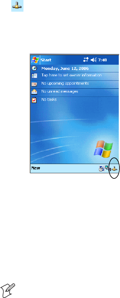
Programming—Chapter 7
209700 Series Color Mobile Computer User’s Manual
For examples on how to use events, consult the Microsoft Developer Net-
work Library at www.msdn.com. The MSDN Library is an essential re-
source for developers using Microsoft tools, products, and technologies. It
contains a bounty of technical programming information, including sam-
ple code, documentation, technical articles, and reference guides.
Autostart FTP
This automatically starts the FTP Server (FTPDCE.EXE) when the 700
Color Computer is powered on. This is provided with the NDISTRAY
program (the Network Driver Interface Specification tray application),
which displays the popup menu that currently allows you to load and un-
load the network drivers. Tap the antenna icon in the System Tray of the
Today screen (a sample antenna icon is circled below) for this pop-up menu.
The default is to start the FTP Server at boot time, unless the following
registry entry is defined and set to “0” which disables AutoFTP. “1” en-
ables the AutoFTP. The entry can be set from the NDISTRAY pop-up
menu by selecting either AutoFTP On or AutoFTP Off.
HKEY_LOCAL_MACHINE\Software\Intermec\Ndistray\StartupIFTP
These new entries are located below the selections to load the network
drivers. If the StartupIFTP registry key is not defined, the FTP Server is
loaded by default, to provide “out-of-the-box” capability for customers
who want to begin loading files to the 700 Color Computer without any
prior configuration.
Note: If a network driver is unloaded using the NDISTRAY popup menu,
and the FTP Server is running, the FTP Server is stopped.
On a resume, if AutoFTP is enabled and the FTP Server is running, it is
stopped and restarted. NDISTRAY uses a helper application named
RESETIFTP to implement the restart on resume feature.
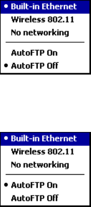
ProgrammingChapter —7
210 700 Series Color Mobile Computer User’s Manual
To do an AutoFTP Installation Check:
1Ensure the FTP Server is running “out-of-the-box” the first time.
2Tap Start >Today to access the Today screen, then tap the antenna
icon in the System Tray to bring up the NDISTRAY pop-up menu.
Select AutoFTP Off to disable AutoFTP. Do a warm boot and confirm
the FTP Server is not running.
3Tap Start >Today to access the Today screen, then tap the antenna
icon in the System Tray to bring up the NDISTRAY pop-up menu.
Select AutoFTP On to enable AutoFTP, reboot, confirm it is running.
4Unload the network driver when the FTP Server is running and con-
firm that it is not running any more.
5Load the FTP Server, establish a connection, then suspend and resume.
The server should still run, but the FTP connection to the client should
be dropped.
Kernel I/O Controls
This describes the KernelIoControl() functions available to application
programmers. Most C++ applications will need to prototype the function
as the following to avoid link and compile errors.
extern “C” BOOL KernelIoControl(DWORD dwIoControlCode, LPVOID lpInBuf, DWORD
nInBufSize, LPVOID lpOutBuf, DWORD nOutBufSize, LPDWORD lpBytesReturned);
You can also see the Device Resource Kit in the Intermec Developer Li-
brary (IDL) for information about these functions. The IDL is available as
a download from the Intermec web site at www.intermec.com/idl. Contact
your Intermec representative for more information.
IOCTL_HAL_GET_DEVICE_INFO
This IOCTL returns either the platform type or the OEMPLATFORM
namebasedonaninputvalue.
Syntax
BOOL KernelIoControl( IOCTL_HAL_GET_DEVICE_INFO, LPVOID lpInBuf, DWORD
nInBufSize, LPVOID lpOutBuf, DWORD nOutBufSize, LPDWORD lpBytesReturned );

Programming—Chapter 7
211700 Series Color Mobile Computer User’s Manual
Parameters
lpInBuf Points to a DWORD containing either the
SPI_GETPLATFORMTYPE or SPI_GETOEMINFO value.
lpInBufSize Must be set to sizeof(DWORD).
lpOutBuf Must point to a buffer large enough to hold the return data of the
function. If SPI_GETPLATFORMTYPE is specified in lpInBuf,
then the “PocketPC\0” Unicode string is returned. If SPI_GE-
TOEMINFO is specified in lpInBuf, then the “Intermec 700\0”
Unicode string is returned.
nOutBufSize ThesizeoflpOutBuf in bytes. Must be large enough to hold the
string returned.
lpBytesReturned The actual number of bytes returned by the function for the data
requested.
Return Values
Returns TRUE if function succeeds. Returns FALSE if the function fails.
GetLastError() may be used to get the extended error value.
IOCTL_HAL_ITC_READ_PARM
Usage
#include “oemioctl.h”
Syntax
BOOL KernelIoControl( IOCTL_HAL_ITC_READ_PARM,LPVOID lpInBuf,DWORD
nInBufSize,LPVOID lpOutBuf,DWORD nOutBufSize,LPDWORD lpBytesReturned );
Parameters
lpInBuf Points to this structure. See “ID Field Values”below.
struct PARMS {
BYTE id;
BYTE ClassId;
};
nInBufSize Must be set to the size of the PARMS structure.
lpOutBuf Must point to a buffer large enough to hold the return data of the
function. If this field is set to NULL and nOutBufSize is set to zero
when the function is called the function will return the number
bytes required by the buffer.
nOutBufSize ThesizeoflpOutBuf in bytes.
lpBytesReturned Number of bytes returned by the function for the data requested.
Return Values
Returns TRUE if function succeeds. Returns FALSE if the function fails.
GetLastError() may be used to get the error value. Either
ERROR_INVALID_PARAMETER or
ERROR_INSUFFICIENT_BUFFER may be returned when this function
is used to get the error.

ProgrammingChapter —7
212 700 Series Color Mobile Computer User’s Manual
ID Field Values
The id field of the PARMS structure may be one of the following values:
ID Field Values
ITC_NVPARM_ETHERNET_ID
Returns Ethernet 802.11b or 802.11b/g MAC Address. Six bytes returned in buffer pointed to by lpOutBuffer
ITC_NVPARM_SERIAL_NUM
Returns serial number of device in BCD format. Six bytes returned in buffer pointed to by lpOutBuffer
ITC_NVPARM_MANF_DATE
Returns device manufacture date in BCD YYYY/MM/DD format. 4 bytes sent in buffer pointed to by lpOutBuffer
ITC_NVPARM_SERVICE_DATE
Returns last device service date in BCD YYYY/MM/DD format. Four bytes sent in buffer pointed to by lpOutBuffer
ITC_NVPARM_DISPLAY_TYPE
Returns device display type. One byte returned in buffer pointed to by lpOutBuffer
ITC_NVPARM_EDG_IP
Returns device Ethernet debug IP address. Four bytes returned in buffer pointed to by lpOutBuffer
ITC_NVPARM_EDBG_SUBNET
Returns device Ethernet debug subnet mask. Four bytes returned in buffer pointed to by lpOutBuffer
ITC_NVPARM_ECN
Returns ECNs applied to device in bit array format. Four bytes returned in buffer pointed to by lpOutBuffer
ITC_NVPARM_CONTRAST
Returns device default contrast setting. Two bytes returned in buffer pointed to by lpOutBuffer
ITC_NVPARM_MCODE
Returns manufacturing configuration code for device. Sixteen bytes returned in buffer pointed to by lpOutBuffer
ITC_NVPARM_VERSION_NUMBER
Returns firmware version for various system components. These values for ClassId field of PARMS structure are
allowed when ITC_NVPARM_VERSION_NUMBER used in id field:
SVN_CLASS_KBD Returns five-byte string, including null terminator, with ASCII value representing keypad
microprocessor version in system. String format is x.xx with terminating null character.
SVN_CLASS_ASIC Returns five-byte string, including null terminator, with ASCII value representing version of
FPGA firmware in system. String format is x.xx with terminating null character.
SVN_CLASS_BOOTSTRAP Returns five-byte string, including null terminator, with ASCII value representing
version of Bootstrap Loader firmware in system. String format is x.xx with terminating null character.
ITC_NVPARM_INTERMEC_SOFTWARE_CONTENT
Reads manufacturing flag bits from non-volatile data store dictating certain software parameters. BOOLEAN
DWORD returned in buffer pointed to by lpOutBuffer indicating whether Intermec Content enabled in XIP
regions. TRUE indicates enabled. FALSE is not enabled.
ITC_NVPARM_ANTENNA_DIVERSITY
Reads state of antenna diversity flag. BOOLEAN DWORD returned in buffer pointed to by lpOutBuffer indicating
whether diversity antenna is installed. TRUE indicates installed. FALSE is not installed.
ITC_NVPARM_WAN_RI
Reads state of WAN ring indicator flag. BOOLEAN DWORD returned in buffer pointed to by lpOutBuffer
indicating polarity of WAN RI signal. TRUE indicates active high. FALSE is active low.
ITC_NVPARM_RTC_RESTORE
Reads state of real-time clock restore flag. BOOLEAN DWORD returned in buffer pointed to by lpOutBuffer.
TRUE indicates RTC is restored on cold-boot. FALSE is RTC is not restored.
ITC_NVPARM_INTERMEC_DATACOLLECTION_SW
Reads state of data collection software enabled flag. BOOLEAN DWORD returned in buffer pointed to by
lpOutBuffer indicating data collection software installs at boot time. FALSE is do not install data collection software

Programming—Chapter 7
213700 Series Color Mobile Computer User’s Manual
ID Field Values (continued)
ITC_NVPARM_INTERMEC_DATACOLLECTION_HW
Reads data collection hardware flags. BYTE returned in buffer pointer to by lpOutBuffer indicating type of data
collection hardware installed. Maximum value returned is ITC_DEVID_SCANHW_MAX:
SITC_DEVID_SCANHW_NONE No scanner hardware installed.
SITC_DEVID_OEM2D_IMAGER OEM 2D imager installed.
SITC_DEVID_INTERMEC2D_IMAGER Intermec 2D imager installed.
SITC_DEVID_SE900_LASER SE900 laser installed.
SITC_DEVID_SE900HS_LASER SE900HS laser installed.
SITC_DEVID_INTERMEC_EVIO EVIO linear imager installed.
High bit non-zero value indicates S6 scanning engine is installed. Bit mask is ITC_DEVID_S6ENGINE_MASK.
ITC_NVPARM_WAN_INSTALLED
Reads state of WAN radio installed flag. BOOLEAN DWORD is returned in buffer: TRUE = WAN radio installed.
ITC_NVPARM_WAN_FREQUENCY
Reads state of WAN radio frequency flag. BOOLEAN DWORD is returned in buffer: TRUE indicates WAN radio
frequency is United States. FALSE is a European WAN radio frequency.
ITC_NVPARM_WAN_RADIOTYPE
Reads WAN radio ID installed by manufacturing. BYTE returned in buffer pointer to by lpOutBuffer indicating type
of WAN radio hardware installed. Maximum value returned is ITC_DEVID_WANRADIO_MAX:
SITC_DEVID_WANRADIO_NONE No WAN radio installed
SITC_DEVID_WANRADIO_SIERRA_SB555 CDMA Sierra Wireless radio
SITC_DEVID_WANRADIO_XIRCOM_GEM3503 GSM/GPRS Intel (Xircom) radio
SITC_DEVID_WANRADIO_SIEMENS_MC45 GSM/GPRS Siemens radio
SITC_DEVID_WANRADIO_SIEMENS_MC46 GSM/GPRS Siemens radio
ITC_NVPARM_80211_INSTALLED
Reads state of 802.11b or b/g radio installed flag. BOOLEAN DWORD returned in buffer: TRUE = radio installed.
ITC_NVPARM_80211_RADIOTYPE
Reads 802.11b or b/g radio ID installed by manufacturing. BYTE returned in buffer pointer to by lpOutBuffer
indicates type of radio hardware installed. ITC_DEVID_80211RADIO_MAX is maximum value returned:
SITC_DEVID_80211RADIO_NONE No 802.11b or 802.11b/g radio installed.
SITC_DEVID_80211RADIO_INTEL_2011B Intel 2011B radio installed.
ITC_NVPARM_BLUETOOTH_INSTALLED
Reads state of Bluetooth radio installed flag. BOOLEAN DWORD returned in buffer pointed to by lpOutBuffer.
TRUE indicates Bluetooth radio installed. FALSE is no Bluetooth radio installed.
ITC_NVPARM_SERIAL2_INSTALLED
Reads state of serial 2 (COM2) device installed flag. BOOLEAN DWORD returned in buffer pointed to by
lpOutBuffer. TRUE indicates serial 2 device is installed. FALSE is no serial 2 device is installed.
ITC_NVPARM_VIBRATE_INSTALLED
Reads state of vibrate device installed flag. BOOLEAN DWORD is returned in buffer pointed to by lpOutBuffer.
TRUE indicates vibrate device is installed. FALSE is no vibrate device is installed.
ITC_NVPARM_LAN9000_INSTALLED
Reads state of Ethernet device installed flag. BOOLEAN DWORD is returned in buffer pointed to by lpOutBuffer.
TRUE indicates Ethernet device is installed. FALSE is no Ethernet device is installed.
ITC_NVPARM_SIM_PROTECT_HW_INSTALLED
Reads state of SIM card protection hardware installed flag. BOOLEAN DWORD returned in buffer pointed to by
lpOutBuffer. TRUE indicates SIM card protection hardware installed. FALSE is no such hardware installed.
ITC_NVPARM_SIM_PROTECT_SW_INSTALLED
Reads state of SIM card protection software installed flag. BOOLEAN DWORD returned in buffer pointed to by
lpOutBuffer. TRUE indicates SIM card protection software is installed. FALSE is no such software installed.

ProgrammingChapter —7
214 700 Series Color Mobile Computer User’s Manual
IOCTL_HAL_ITC_WRITE_SYSPARM
Describes and enables the registry save location.
Usage
#include “oemioctl.h”
Syntax
BOOL KernelIoControl( IOCTL_HAL_ITC_WRITE_SYSPARM,LPVOID lpInBuf,DWORD
nInBufSize, LPVOID lpOutBuf, DWORD nOutBufSize, LPDWORD lpBytesReturned );
Parameters
lpInBuf Asinglebytethatmaybeoneoftheid values. See “ID Field Values”
on the next page.
nInBufSize Must be set to the size of the lpInBuf in bytes.
lpOutBuf Must point to a buffer large enough to hold the data to be written
to the non-volatile data store.
nOutBufSize ThesizeoflpOutBuf in bytes.
lpBytesReturned The number of bytes returned by the function.
Return Values
Returns TRUE if function succeeds. Returns FALSE if the function fails.
GetLastError() may be used to get the error value. Either
ERROR_INVALID_PARAMETER or
ERROR_INSUFFICIENT_BUFFER may be returned when this function
is used to get the error.
ID Field Values
The id field of lpInBuf may be one of the following values:
ID Field Values
ITC_REGISTRY_SAVE_ENABLE
Enables or disables the save registry to non-volatile media feature of the RegFlushKey() function. lpOutBuf must be
set to zero (FALSE) if the feature is to be disabled or one (TRUE) if the feature is to be enabled.
ITC_ DOCK_SWITCH
This IOCTL sets a position of the dock switch. The dock switch may be set to either “modem” or “serial” positions.
lpOutBuf must point to a buffer that contains a byte value of either DOCK_MODEM or DOCK_SERIAL as
defined in OEMIOCTL.H; the value specifies the position the switch is to be set. The call appears as follows:
// port = DOCK_MODEM or DOCK_SERIAL as defined in oemioctl.h
BOOL SetDockSwitch( BYTE port)
{
DWORD cmd = ITC_DOCK_SWITCH;
DWORD cbRet;
return KernelIoControl(IOCTL_HAL_ITC_WRITE_SYSPARM,&cmd, sizeof(cmd),
&port,sizeof(port),&cbRet)
}

Programming—Chapter 7
215700 Series Color Mobile Computer User’s Manual
ID Field Values (continued)
ITC_ WAKEUP_MASK
This IOCTL sets a bit mask that represents the mask for the five programmable wakeup keys. The I/O key is not a
programmable wakeup key. By default it is always the system resume key and all other keys are set to disable key
wakeup. A zero in a bit position masks the wakeup for that key. A one in a bit position enables wakeup for that key.
lpOutBuf must point to a buffer that contains a byte value of a wakeup mask consisting of the OR’ed constants as
definedinOEMIOCTL.H.Onlythefollowingkeysareprogrammableaswakeupevents.
#define SCANNER_TRIGGER 1
#define SCANNER_LEFT 2
#define SCANNER_RIGHT 4
#define GOLD_A1 8
#define GOLD_A2 0x10
ITC_AMBIENT_KEYBOARD (does not apply to the 730 Computer)
This IOCTL sets the threshold for the keypad ambient sensor. This can be a value from 0 (always off) to 255 (always
on). lpOutBuf must point to a buffer that contains a byte value of the desired setting.
ITC_AMBIENT_FRONTLIGHT (does not apply to the 730 Computer)
This IOCTL sets the threshold for the frontlight ambient sensor. This can be a value from 0 (always off) to 255.
lpOutBuf must point to a buffer that contains a byte value of the desired setting.
IOCTL_HAL_GET_DEVICEID
This returns the device ID. There are two types of device IDs supported,
which are differentiated based on the size of the output buffer. The UUID
is returned if the buffer size is set to sizeof(UNIQUE_DEVICEID),other-
wisetheoldstyledeviceIDisreturned.
Usage
#include “pkfuncs.h”
#include “deviceid.h”
Syntax
BOOL KernelIoControl( IOCTL_HAL_GET_DEVICEID,LPVOID lpInBuf,DWORD
nInBufSize,LPVOID lpOutBuf,DWORD nOutBufSize,LPDWORD lpBytesReturned );
Parameters
lpInBuf Should be set to NULL. STRICT_ID settings are not supported.
lpInBufSize Should be set to zero.
lpOutBuf Must point to a UNIQUE_DEVICEID structure as defined by
DEVICEID.H if the UUID is to be returned
nOutBufSize The size of the UNIQUE_DEVICEID in bytes if the UUID is to
be returned. A DEVICE_ID as defined by PKFUNCS.H is re-
turned if the size in bytes is greater than or equal to sizeof(DE-
VICE_ID).
lpBytesReturned The number of bytes returned by the function.
Return Values
Returns TRUE if function succeeds. Returns FALSE if the function fails.
GetLastError() may be used to get the extended error value.

ProgrammingChapter —7
216 700 Series Color Mobile Computer User’s Manual
IOCTL_HAL_GET_OAL_VERINFO
Returns the HAL version information of the Pocket PC image.
Usage
#include “oemioctl.h”
Syntax
BOOL KernelIoControl( IOCTL_HAL_GET_OAL_VERINFO,LPVOID lpInBuf,DWORD
nInBufSize,LPVOID lpOutBuf,DWORD nOutBufSize,LPDWORD lpBytesReturned );
Parameters
lpInBuf Should be set to NULL.
lpInBufSize Should be set to zero.
lpOutBuf Must point to a VERSIONINFO structure as defined by
OEMIOCTL.H. The fields should have these values:
Scboemverinfo sizeof (tagOemVerInfo);
Sverinfover 1
Ssig; “ITC\0”
Sid; ‘N’
Stgtcustomer “”
Stgtplat SeaRay
Stgtplatversion Current build version number
Stgtcputype[8]; “Intel\0”
Stgtcpu “PXA255\0”;
Stgtcoreversion “”
Sdate Build time
Stime Build date
nOutBufSize ThesizeofVERSIONINFOinbytes.
lpBytesReturned Returns sizeof(PVERSIONINFO).
Return Values
Returns TRUE if function succeeds. Returns FALSE if the function fails.
GetLastError() may be used to get the extended error value.
IOCTL_HAL_GET_BOOTLOADER_VERINFO
Returns the HAL version information of the Pocket PC image.
Usage
#include “oemioctl.h”
Syntax
BOOL KernelIoControl( IOCTL_HAL_GET_OAL_VERINFO,LPVOID lpInBuf, DWORD
nInBufSize,LPVOID lpOutBuf,DWORD nOutBufSize,LPDWORD lpBytesReturned );
Parameters
lpInBuf Should be set to NULL.
nInBufSize Should be set to zero.

Programming—Chapter 7
217700 Series Color Mobile Computer User’s Manual
lpOutBuf Must point to a VERSIONINFO structure as defined by
OEMIOCTL.H. The fields should have these values:
Scboemverinfo Sizeof (tagOemVerInfo);
Sverinfover 1
Ssig; “ITC\0”
Sid; ‘B’
Stgtcustomer “”
Stgtplat SeaRay
Stgtplatversion Current build version number of the
bootstrap loader
Stgtcputype[8]; “Intel\0”;
Stgtcpu “PXA255\0”
Stgtcoreversion “”
Sdate Build time
Stime Build date
nOutBufSize ThesizeofVERSIONINFOinbytes.
lpBytesReturned The number of bytes returned to lpOutBuf.
Return Values
Returns TRUE if function succeeds. Returns FALSE if the function fails.
GetLastError() may be used to get the extended error value.
IOCTL_HAL_WARMBOOT
Causes the system to perform a warm-boot. The object store is retained.
Usage
#include “oemioctl.h”
Syntax
BOOL KernelIoControl( IOCTL_HAL_WARMBOOT,LPVOID lpInBuf,DWORD
nInBufSize,LPVOID lpOutBuf,DWORD nOutBufSize,LPDWORD lpBytesReturned );
Parameters
lpInBuf Should be set to NULL.
lpInBufSize Should be set to zero.
lpOutBuf Should be NULL.
nOutBufSize Should be zero.
Return Values
None.
IOCTL_HAL_COLDBOOT
Causes the system to perform a cold-boot. The object store is cleared.
Usage
#include “oemioctl.h”
Syntax
BOOL KernelIoControl( IOCTL_HAL_COLDBOOT,LPVOID lpInBuf,DWORD
nInBufSize,LPVOID lpOutBuf,DWORD nOutBufSize,LPDWORD lpBytesReturned );

ProgrammingChapter —7
218 700 Series Color Mobile Computer User’s Manual
Parameters
lpInBuf Should be set to NULL.
lpInBufSize Should be set to zero.
lpOutBuf Should be NULL.
nOutBufSize Should be zero.
Return Values
None.
IOCTL_HAL_GET_RESET_INFO
This code allows software to check the type of the most recent reset.
Usage
#include “oemioctl.h”
Syntax
BOOL KernelIoControl( IOCTL_HAL_GET_RESET_INFO,LPVOID lpInBuf,DWORD
nInBufSize,LPVOID lpOutBuf,DWORD nOutBufSize,LPDWORD lpBytesReturned );
Parameters
lpInBuf Should be set to NULL.
lpInBufSize Should be set to zero.
lpOutBuf Must point to a HAL_RESET_INFO structure. See sample below.
nOutBufSize The size of HAL_RESET_INFO in bytes.
lpBytesReturned The number of bytes returned by the function.
Return Values
Returns TRUE if function succeeds. Returns FALSE if the function fails.
GetLastError() may be used to get the extended error value.
Sample
typedef struct {
DWORD ResetReason; // most recent reset type
DWORD ObjectStoreState; // state of object store
} HAL_RESET_INFO, * PHAL_RESET_INFO;
// Reset reason types
#define HAL_RESET_TYPE_UNKNOWN 0
#define HAL_RESET_REASON_HARDWARE 1 // cold
#define HAL_RESET_REASON_SOFTWARE 2 // suspend
#define HAL_RESET_REASON_WATCHDOG 4
#define HAL_RESET_BATT_FAULT 8 // power fail
#define HAL_RESET_VDD_FAULT 16 // warm boot
// Object store state flags
#define HAL_OBJECT_STORE_STATE_UNKNOWN 0
#define HAL_OBJECT_STORE_STATE_CLEAR 1

Programming—Chapter 7
219700 Series Color Mobile Computer User’s Manual
IOCTL_HAL_GET_BOOT_DEVICE
This IOCTL code allows software to check which device CE booted from.
Usage
#include “oemioctl.h”
Syntax
BOOL KernelIoControl( IOCTL_HAL_GET_BOOT_DEVICE,LPVOID lpInBuf,DWORD
nInBufSize,LPVOID lpOutBuf,DWORD nOutBufSize,LPDWORD lpBytesReturned );
Parameters
lpInBuf Should be set to NULL.
lpInBufSize Should be set to zero.
lpOutBuf Must point to a buffer large enough to hold a DWORD (4 bytes)
with the boot device. The following boot devices are supported:
#define HAL_BOOT_DEVICE_UNKNOWN 0
#define HAL_BOOT_DEVICE_ROM_XIP 1
#define HAL_BOOT_DEVICE_ROM 2
#define HAL_BOOT_DEVICE_PCMCIA_ATA 3
#define HAL_BOOT_DEVICE_PCMCIA_LINEAR 4
#define HAL_BOOT_DEVICE_IDE_ATA 5
#define HAL_BOOT_DEVICE_IDE_ATAPI 6
nOutBufSize ThesizeoflpOutBuf in bytes (4).
lpBytesReturned The number of bytes returned by the function.
Return Values
Returns TRUE if function succeeds. Returns FALSE if the function fails.
GetLastError() may be used to get the extended error value.
IOCTL_HAL_REBOOT
Note: Using this is no longer recommended, use IOCTL_HAL_WARM-
BOOT (page 217) or IOCTL_HAL_COLDBOOT (page 217). This is
supported for backward-compatibility but its use can lead to difficulties.
Causes the system to perform a warm-boot. The object store is retained.
Usage
#include “oemioctl.h”
Syntax
BOOL KernelIoControl( IOCTL_HAL_REBOOT,LPVOID lpInBuf,DWORD nInBufSize,LPVOID
lpOutBuf,DWORD nOutBufSize,LPDWORD lpBytesReturned );
Parameters
lpInBuf Should be set to NULL. lpOutBuf Should be NULL.
lpInBufSize Should be set to zero. nOutBufSize Should be zero.
Return Values
None.

ProgrammingChapter —7
220 700 Series Color Mobile Computer User’s Manual
IOCTL_PROCESSOR_INFORMATION
Returns processor information.
Usage
#include “pkfuncs.h”
Syntax
BOOL KernelIoControl( IOCTL_PROCESSOR_INFORMATION,LPVOID lpInBuf,DWORD
nInBufSize,LPVOID lpOutBuf,DWORD nOutBufSize,LPDWORD lpBytesReturned );
Parameters
lpInBuf Should be set to NULL.
nInBufSize Should be set to zero.
lpOutBuf Should be a pointer to the PROCESSOR_INFO structure. Its
structure stores information describing the CPU more descriptively.
typedef __PROCESSOR_INFO {
WORD wVersion; // Set to value 1
WCHAR szProcessorCore[40]; // “ARM\0”
WORD wCoreRevision; // 4
WCHAR szProcessorName[40]; // “PXA255\0”
WORD wProcessorRevision; // 0
WCHAR szCatalogNumber[100]; // 0
WCHAR szVendor[100]; // “Intel Corporation\0”
DWORD dwInstructionSet; // 0
DWORD dwClockSpeed; // 400
}
nOutBufSize Should be set to sizeof(PROCESSOR_INFO) in bytes.
lpBytesReturned Returns sizeof(PROCESSOR_INFO);
Return Values
Returns TRUE if function succeeds. Returns FALSE if the function fails.
GetLastError() may be used to get the extended error value.
IOCTL_GET_CPU_ID
Returns Xscale processor ID.
Usage
#include “oemioctl.h”
Syntax
BOOL KernelIoControl( IOCTL_GET_CPU_ID,LPVOID lpInBuf, DWORD nInBufSize,LPVOID
lpOutBuf,DWORD nOutBufSize,LPDWORD lpBytesReturned );
Parameters
lpInBuf ShouldpointtoaCPUIdInfostructuredefinedinOEMIOCTL.H.
lpInBufSize Should be sizeof(CPUIdInfo).

Programming—Chapter 7
221700 Series Color Mobile Computer User’s Manual
lpOutBuf Should be NULL.
nOutBufSize Should be set to 0.
lpBytesReturned Returns sizeof(PROCESSOR_INFO);
Return Values
Returns TRUE if function succeeds. Returns FALSE if the function fails.
GetLastError() may be used to get the extended error value.
Network Selection APIs
Network Selection APIs change the network adapter configuration pro-
grammatically. See the Communications Resource Kit in the IDL for in-
formation about these APIs. The IDL is available as a download from the
Intermec web site at www.intermec.com/idl. Contact your Intermec repre-
sentative for more information.
Notifications
Use the following information to programmatically control the vibrator, to
write an application to turn on the vibrator when a message is received via
the WLAN radio link, and turn it off when the user hits a key.
Vibrator support is in the NLED driver as a false LED. The vibrator is
LED 5 and identified with an CycleAdjust of –1. The vibrate option is
available in the notifications panel when the vibrator is in the system.
Regarding an applications interface to NLED.DLL, LEDs must be avail-
able for applications to use through the COREDLL.DLL file. To use the
LED functions, declare these as extern ”C” as follows:
extern ”C” BOOL WINAPI NLEDGetDeviceInfo(UINT nInfoId, void *pOutput);
extern ”C” BOOL WINAPI NLEDSetDevice( UINT nDeviceId, void *pInput);
The LEDs are enumerated for access through the data structures associated
with these APIs:
SNotification LED 0
SRadio On LED 1 (does not apply to the 730 Computer)
SAlpha Lock LED 2
SScanner LED 3
SLow Battery 4
SVibrator 5 (does not apply to the 730 Computer)
NLEDGetDeviceInfo
Usage
#include “nled.h”
Syntax
BOOL NLEDGetDeviceInfo ( UINT nInfoId, void *pOutput );

ProgrammingChapter —7
222 700 Series Color Mobile Computer User’s Manual
Parameters
nInfoId Integer specifying the information to return. These values are defined:
NLED_COUNT_INFO pOutput buffer specifies the number of LEDs on the device.
NLED_SUPPORTS_INFO_ID pOutput buffer specifies information about the capabilities
supported by the LED.
NLED_SETTINGS_INFO_ID pOutput buffer has information about LED current settings.
pOutput Pointer to the buffer to which the information is returned. The buffer points to various structure
types defined in “nled.h”, depending on the value of nId, as detailed in the following table:
Value of nID Structure in pOutput
LED_COUNT_INFO NLED_COUNT_INFO
NLED_SUPPORTS_INFO NLED_SUPPORTS_INFO
NLED_SETTINGS_INFO NLED_SETTINGS_INFO
NLEDSetDevice
Usage
#include “nled.h”
Syntax
BOOL NLEDSetDevice ( UINT nDeviceId, void *pInput );
Parameters
nDeviceId Integer specifying the device identification. The following is defined:
NLED_SETTINGS_INFO_ID Contains information about the desired LED settings.
pInput Pointer to the buffer that contains the NLED_SETTINGS_INFO structure.
Reboot Functions
There are several methods, via Kernel I/O Control functions, that an ap-
plication program can use to force the 700 Color Computer to reboot.
You can also see the Device Resource Kit in the IDL for information
about these functions. The IDL is available as a download from the Inter-
mec web site at www.intermec.com/idl. Contact your Intermec representa-
tive for information.
SIOCTL_HAL_REBOOT
This performs a warm-boot (page 219). See note below.
SIOCTL_HAL_COLDBOOT
Forces a cold reboot. This resets the 700 Color Computer, reloads Win-
dows CE as if a power-up was performed, and discards the contents of
the Windows CE RAM-based object store (page 217).
SIOCTL_HAL_WARMBOOT
Performs a system warm-boot, preserving the object store (page 217).
Note: Using IOCTL_HAL_REBOOT is no longer recommended, use
either IOCTL_HAL_WARMBOOT or IOCTL_HAL_COLDBOOT.
IOCTL_HAL_REBOOT is still supported for backward-compatibility
but its use can lead to difficulties.

Programming—Chapter 7
223700 Series Color Mobile Computer User’s Manual
Remapping the Keypad
Note: Use caution when remapping the keypad. Improper remapping may
render the keypad unusable. Data within the 700 Color Computer could
also be lost, should any problems occur.
Applications have the ability to remap keys on the 700 Color Numeric
Keypad and 700 Color Alphanumeric Keypad. This will allow applications
to enable keys that would otherwise not be available, such as the [F1]
function key. Also, to disable keys that should not be available, such as the
alpha key because no alpha entry is required. Care should be exercised
when attempting to remap the keypad because improper remapping may
cause the keypad to become unusable. This can be corrected by cold boot-
ing the device which loads the default keymap again.
Note that remapping the keys in this way affects the key mapping for the
entire system, not just for the application that does the remapping.
There are three “planes” supported for the 700 Color Numeric Keypad
and Alphanumeric Keypad. Keys that are to be used in more than one shift
plane must be described in each plane.
Unshifted Plane
The unshifted plane contains values from the keypad when not pressed
with other keys, such as the following:
Press the Keys
Numeric Keypad Alphanumeric Keypad To Enter This
1M1
5T5
9Y9
Gold Plane
The gold plane contains values from the keypad when a key is simulta-
neously pressed with the [Gold] bkey on the numeric keypad or the
[Gold/White] ckey on the alphanumeric keypad, such as the following:
Press the Keys
Numeric Keypad Alphanumeric Keypad To Enter This
[Gold] b1[Gold/White] ce Send
[Gold] b5[Gold/White] cC A3
[Gold] b9[Gold/White] cP PgDn

ProgrammingChapter —7
224 700 Series Color Mobile Computer User’s Manual
Alpha (Blue) Plane
The alpha plane contains values from the keypad when the keypad has
been placed in alpha mode by pressing the blue alpha key, such as:
Press the Keys
Numeric Keypad Alphanumeric Keypad To Enter This
[Alpha] F1[Alpha] dg Caps
[Alpha] F5[Alpha] dJ j
[Alpha] F9[Alpha] dW w
Key Values
Key values are stored in the registry. All units ship with a default key
mapping in its registry. Applications to change the default mapping need
to read the appropriate key from the registry into an array of Words,
modify the values required and then write the updated values back into the
registry. The registry access can be done with standard Microsoft API calls,
such as RegOpenKeyEx(), RegQueryValueEx(), and RegSetValueEx().
Numeric Keypad
The following registry keys contain the plane mappings:
SThe unshifted plane mapping can be found in the registry at:
HKEY_LOCAL_MACHINE\HARDWARE\DEVICEMAP\KEYBD\Vkey
SThe gold plane mapping can be found in the registry at:
HKEY_LOCAL_MACHINE\HARDWARE\DEVICEMAP\KEYBD\VkeyGold
SThe alpha plane mapping can be found in the registry at:
HKEY_LOCAL_MACHINE\HARDWARE\DEVICEMAP\KEYBD\VkeyAlpha
Alphanumeric Keypad
The following registry keys contain the plane mappings:
SThe unshifted plane mapping can be found in the registry at:
HKEY_LOCAL_MACHINE\HARDWARE\DEVICEMAP\KEYBD\ALPHA\Vkey
SThe gold plane mapping can be found in the registry at:
HKEY_LOCAL_MACHINE\HARDWARE\DEVICEMAP\KEYBD\ALPHA\VkeyGold
SThe alpha plane mapping can be found in the registry at:
HKEY_LOCAL_MACHINE\HARDWARE\DEVICEMAP\KEYBD\ALPHA\VkeyAlpha
How Key Values Are Stored in Registry
To know which fields to update in the registry, you must know what Scan
Codes are assigned to each physical key (see the “Keypad Scan Codes and
Meanings” table on the next page). The Scan Code is used at the lowest
level of the system to let the keypad driver know which physical key has
been pressed. The keypad driver takes that scan code and looks it up in a
table (a copy of the one stored in the registry) to determine which values
to pass on to the operating system.

Programming—Chapter 7
225700 Series Color Mobile Computer User’s Manual
Each registry key is just an array that describes to the keypad driver what
value needs to be passed for each physical key. The key values are indexed
by the scan code, this is a zero-based index. For example in the unshifted
plane, the [4] key has a scan code of 0x06. This means that the seventh
word under the “Vkey” registry key will have the value for the [4] key.
Taking a sample of the “Vkey” registry key shows the following values:
00,00,0B,05,02,03,C1,07,04,03,BE,00,34,00,00,00,. . .
The value is 34,00. The values are in reverse byte order as that is the way
the processor handles data. When writing an application, nothing needs to
be done to swap the bytes, as this will happen automatically when the data
is read into a byte value. This is something you just need to be aware of
when looking at the registry. Knowing this, we can see that the value that
the keypad driver will pass to the system is a hex 34. Looking that up on
an UNICODE character chart, we see that it maps to a “4”. If you wanted
the key, labeled “4”, to output the letter “A” instead, you would need to
change the seventh word to “41” (the hexadecimal representation of “A”
from the UNICODE chart), then put the key back into the registry.
If you wish to disable a certain key, remap its scan code to 0x00.
Note: Do not remap scan codes 0x01, 0x41, 0x42, 0x43, 0x44. Doing so
could make your 700 Color Computer unusable until you do a cold-boot.
Change Notification
Changing registry keys does not immediately change key mappings. To
notify the keypad driver the registry is updated, use the CreateEvent() API
to signal the “ITC_KEYBOARD_CHANGE” named event.
Advanced Keypad Remapping
It is also possible to map multiple key presses to one button and to map
named system events to a button. The multiple key press option could be
useful to cut down on the number of keys needed to press in a given situa-
tion or to remap which key behaves like the action key. Mapping events to
a button could be useful to change which buttons will fire the scanner,
control volume, and allow for suspending and resuming the device. Con-
tact Intermec Technical Support for more information.

ProgrammingChapter —7
226 700 Series Color Mobile Computer User’s Manual
Scan Codes
At the lowest driver level, the 700 Color Numeric and Alphanumeric Key-
pads identify keys as scan codes. The keypad microcontroller sends the
codes and only the keypad firmware changes the codes.
Numeric Keypad Scan Codes and Meanings
Press
this Key Meaning ScanCode
Press
this Key Meaning ScanCode
Reserved 0x00 Scanner Left 0x03
II/O button 0x01 Scanner Right 0x04
Scanner Handle Trigger 0x02
44/GHI/A2 0x06 RRight arrow/Tab 0x14
None 0x07 2 2/ABC/End 0x15
LLeft arrow/Back Tab 0x08 88/TUV/* (asterisk) 0x16
None 0x09 0 0/Win 0x17
KBkSp// (forward slash) 0x0A 55/JKL/A3 0x18
b[Gold] key 0x0B None 0x19
None 0x0C AAction/+ (plus symbol) 0x1A
EEsc/– (minus sign) 0x0D 3 3/DEF/backlight 0x1B
DDown arrow/Volume decrease 0x0E 99/WXYZ/PgDn 0x1C
11/Caps/Send 0x0F e Enter/@ (at symbol) 0x1D
77/PQRS/PgUp 0x10 66/MNO/A4 0x1E
F[Alpha] key 0x11 None 0x1F-0x40
None 0x12 BCharge Detect 0x41
UUp arrow/Volume increase 0x13
CLCD frontlight 0x42 Threshold crossed 0x42
bAmbient light 0x42
Headset detected 0x43
Keypad Backlight 0x44 Threshold Crossed 0x44
bAmbient Light 0x44

Programming—Chapter 7
227700 Series Color Mobile Computer User’s Manual
Alphanumeric Keypad Scan Codes and Meanings
Press
this Key Meaning ScanCode
Press
this Key Meaning ScanCode
Reserved 0x00 N N/2 0x17
iI/O button 0x01 II/backlight 0x18
Scanner Handle Trigger 0x02 P P/PgDn 0x19
Scanner Left 0x03 QQ/, (comma) 0x1A
Scanner Right 0x04 R R/+ (plus sign) 0x1B
AA/A1 key 0x05 SS/4 0x1C
BB/A2 key 0x06 T T/5 0x1D
eEscape/Send 0x07 OO/3 0x1E
jLeft arrow/Back Tab 0x08 g Caps/Lock 0x1F
kUp arrow/Volume increase 0x09 hBkSp 0x20
mDown arrow/Volume decrease 0x0A V V/. (period) 0x21
lRight arrow/Tab 0x0B WW/7 0x22
aAction/End 0x0C X X/8 0x23
EE/Win 0x0D UU/6 0x24
FF/= (equal sign) 0x0E c Gold/White 0x25
GG/* (asterisk) 0x0F bNumLock 0x26
CC/A3 0x10 Space 0x27
HH// (forward slash) 0x11 ZZ/0 0x28
DD/A4 0x12 f Enter 0x29
JJ/PgUp 0x13 YY/9 0x2A
KK/@ (as symbol) 0x14 None 0x2B–0x40
LL/– (minus sign) 0x15 BCharge Detect 0x41
MM/1 0x16
CLCD frontlight 0x42 Threshold Crossed 0x42
bAmbient light 0x42
Headset detected 0x43
Keypad Backlight 0x44 Threshold Crossed 0x44
bAmbient Light 0x44
ProgrammingChapter —7
228 700 Series Color Mobile Computer User’s Manual
Sample View of Registry Keys
Below is a sample of the current default key mapping for the 700 Color
Numeric Keypad. See your device registry for the latest key mappings.
[HKEY_LOCAL_MACHINE\HARDWARE\DEVICEMAP\KEYBD]
”ResumeMask”=dword:7
”Vkey”=hex: 00,00,0B,05,02,03,C1,07,04,03,BE,00,34,00,00,00,\
25,00,00,00,08,00,03,02,00,00,1B,00,28,00,31,00,\
37,00,01,02,00,00,26,00,27,00,32,00,38,00,30,00,\
35,00,00,00,01,03,33,00,39,00,0D,00,36,00,00,00,\
00,00,00,00,00,00,00,00,00,00,00,00,00,00,00,00,\
00,00,00,00,00,00,00,00,00,00,00,00,00,00,00,00,\
00,00,00,00,00,00,00,00,00,00,00,00,00,00,00,00,\
00,00,00,00,00,00,00,00,00,00,00,00,00,00,00,00,\
00,00,07,05,01,05,03,05,02,05
”VkeyGold”=hex: 00,00,0B,05,02,03,C1,07,04,03,BE,00,34,00,00,00,\
09,01,00,00,BF,00,03,02,00,00,BD,00,75,00,72,00,\
21,00,01,02,00,00,76,00,09,00,73,00,38,01,5B,00,\
35,00,00,00,BB,01,09,05,22,00,32,01,36,00,00,00,\
00,00,00,00,00,00,00,00,00,00,00,00,00,00,00,00,\
00,00,00,00,00,00,00,00,00,00,00,00,00,00,00,00,\
00,00,00,00,00,00,00,00,00,00,00,00,00,00,00,00,\
00,00,00,00,00,00,00,00,00,00,00,00,00,00,00,00,\
00,00,07,05,01,05,03,05,02,05
”VkeyAlpha”=hex: 00,00,0B,05,02,03,C1,07,04,03,BE,00,47,00,00,00,\
25,00,00,00,08,00,03,02,00,00,1B,00,28,00,02,02,\
50,00,01,02,00,00,26,00,27,00,41,00,54,00,20,00,\
4A,00,00,00,01,03,44,00,57,00,0D,00,4D,00,00,00,\
00,00,00,00,00,00,00,00,00,00,00,00,00,00,00,00,\
00,00,00,00,00,00,00,00,00,00,00,00,00,00,00,00,\
00,00,00,00,00,00,00,00,00,00,00,00,00,00,00,00,\
00,00,00,00,00,00,00,00,00,00,00,00,00,00,00,00,\
00,00,07,05,01,05,03,05,02,05

229700 Series Color Mobile Computer User’s Manual
Configurable Settings
A
This appendix contains information about the Intermec Settings, Utilities,
and Wireless Network applets on the 700 Color Mobile Computer.
Note: “700 Color” pertains to 740, 741, 750, 751, 760, and 761 Com-
puters unless otherwise noted.
The contents of the Intermec Settings applet are dependent on what hard-
ware configuration is done for each 700 Color Computer at the time of
shipment. These settings currently only appear if a scanner or an imager
option is present.
Likewise, other applets that are specifically related to the 802.11b or
802.11b/g radio module appear when a 802.11b or 802.11b/g radio mod-
ule is installed in a 700 Color Computer. Applets that are specific for
Bluetooth, CDMA/1xRTT, and GSM/GPRS radio modules only appear
when each respective hardware configuration is done on the 700 Color
Computer. See Chapter 4, “Network Support,” for more information about
the radio modules or Bluetooth.
Information about using reader commands and configuration bar codes to
configure some of your settings is also in this appendix.
Note: Information about the settings you can configure with the Intermec
Settings applet is described in the Intermec Computer Command Reference
Manual (P/N: 073529). The online manual is available from the Intermec
web site at www.intermec.com.
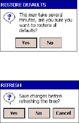
Configurable SettingsAppendix —A
230 700 Series Color Mobile Computer User’s Manual
Configuration Parameters
A configuration parameter changes the way the 700 Color Computer op-
erates, such as configuring a parameter to have the 700 Color Computer
emit a very loud beep in a noisy environment.
To execute configuration parameters, scan EasySet bar codes. You can use
the EasySet bar code creation software from Intermec to print configura-
tion labels. Scan the labels to change the scanner configuration and data
transfer settings.
For more information, see the EasySet online help. EasySet is available
from the Intermec Data Capture web site.
Menus of available parameters for each group are listed. Use the scroll bars
to go through the list. Expand each menu (+) to view its parameter set-
tings. Tap a parameter to select, or expand a parameter (+) to view its sub-
parameters.
Note that each parameter or subparameter is shown with its default setting
or current setting in (< >) brackets. Tap a parameter or subparameter to
select that parameter, then do any of the following to change its setting:
STyping a new value in an entry field.
SChoosing a new value from the drop-down list.
SSelecting a different option. The selected option contains a bullet.
STap Edit >Restore Item Defaults to restore factory-default settings.
Tap Yes when you are prompted to verify this action.
STap View >Refresh to discard changes and start again. Tap Yes to save
changes when you are prompted to verify this action.
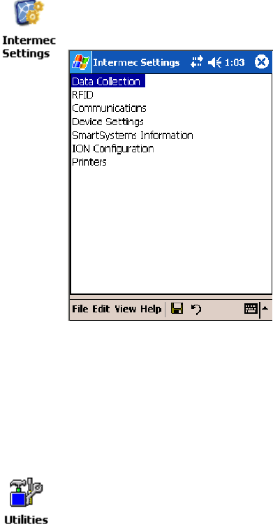
Configurable SettingsAppendix —A
231700 Series Color Mobile Computer User’s Manual
Intermec Settings Applet
Information about the settings you can configure with this applet is
described in the Intermec Computer Command Reference Manual.The
online manual is available from the Intermec web site at
www.intermec.com.
See the Data Collection Resource Kit in the Intermec Developer Library
(IDL) for information about data collection functions. The IDL is avail-
able as a download from the Intermec web site at www.intermec.com/idl.
Contact your Intermec representative for more information.
To access the settings from the 700 Color Computer, tap Start >Settings
>theSystem tab > Intermec Settings to access its applet.
Utilities Applet
The Utilities applet examines and modifies settings and operational modes
of specific hardware and software on the 700 Color Computer: the dock
switch, registry storage, wakeup mask, and application launch keys.
To access the settings from the 700 Color Computer, tap Start >Settings
>theSystem tab > Utilities to access its applet.
Use the left and right arrows to scroll through the tabs along the bottom of
the applet, then tap a tab to access its menus. These tabs represent the fol-
lowing groups of settings or parameters:
SDock Switch (next page)
SRegistry Save (page 232)
SWakeup Mask (page 233)
SApp Launch (page 234)
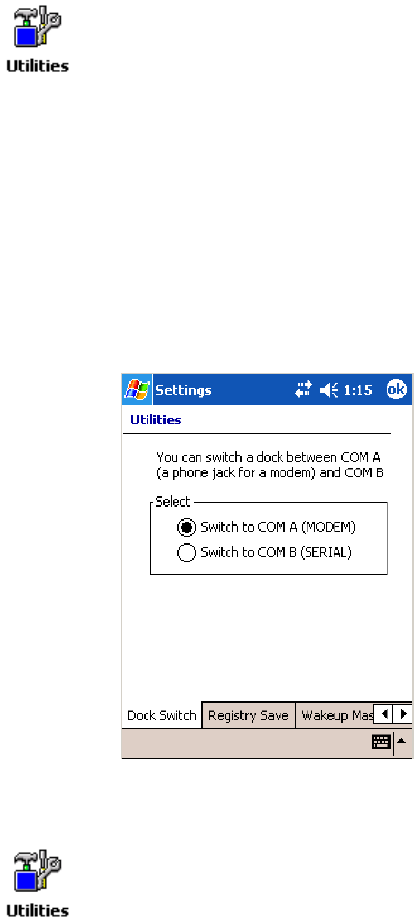
Configurable SettingsAppendix —A
232 700 Series Color Mobile Computer User’s Manual
Dock Switch
From the 700 Color Computer, tap Start >Settings >theSystem tab >
Utilities >theDock Switch tab to access the Dock Switch applet.
Use this applet to control the position of the dock switch. This can be set
either to a COM A (phone jack for a modem) position or to a COM B
(serial) position.
If switched to COM B and suspended, the terminal has the following be-
havior:
SIf the 700 Color Computer is on charge, the dock switch remains
switched to COM B.
SIf the 700 Color Computer is off charge, the dock switch switches to
COM A and remain in this position until the 700 Color Computer re-
sumes charge.
Registry Save
From the 700 Color Computer, tap Start >Settings >theSystem tab >
Utilities >theRegistry Save tab to access the Registry Save applet.
For Windows Mobile 2003, the only medium available for saving the reg-
istry is the Flash File System (PSM). Registry data is stored in the
“\Flash_File_Store\Registry” path. Check Enable Registry Storage to en-
able this function.
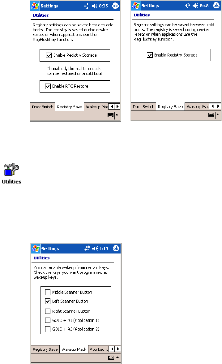
Configurable SettingsAppendix —A
233700 Series Color Mobile Computer User’s Manual
To ensure that the 700 Color Computer restores the real-time clock after a
cold-boot, check the Enable RTC Restore option. Note that this does not
apply to the 730 Computer.
700 Color Screen 730 Screen
Wakeup Mask
From the 700 Color Computer, tap Start >Settings >theSystem tab >
Utilities >theWakeup Mask tab to access the Wakeup Mask applet.
This applet programs three scanner buttons and the A1 and A2 application
keys to be “wakeup” or resume keys. That is, to prompt the 700 Color
Computer to “wake up” or resume activity after going to “sleep” as a result
of being inactive after a length of time. This information will remain be-
tween warm and cold boots.
Check the appropriate box, then tap ok to apply your settings.
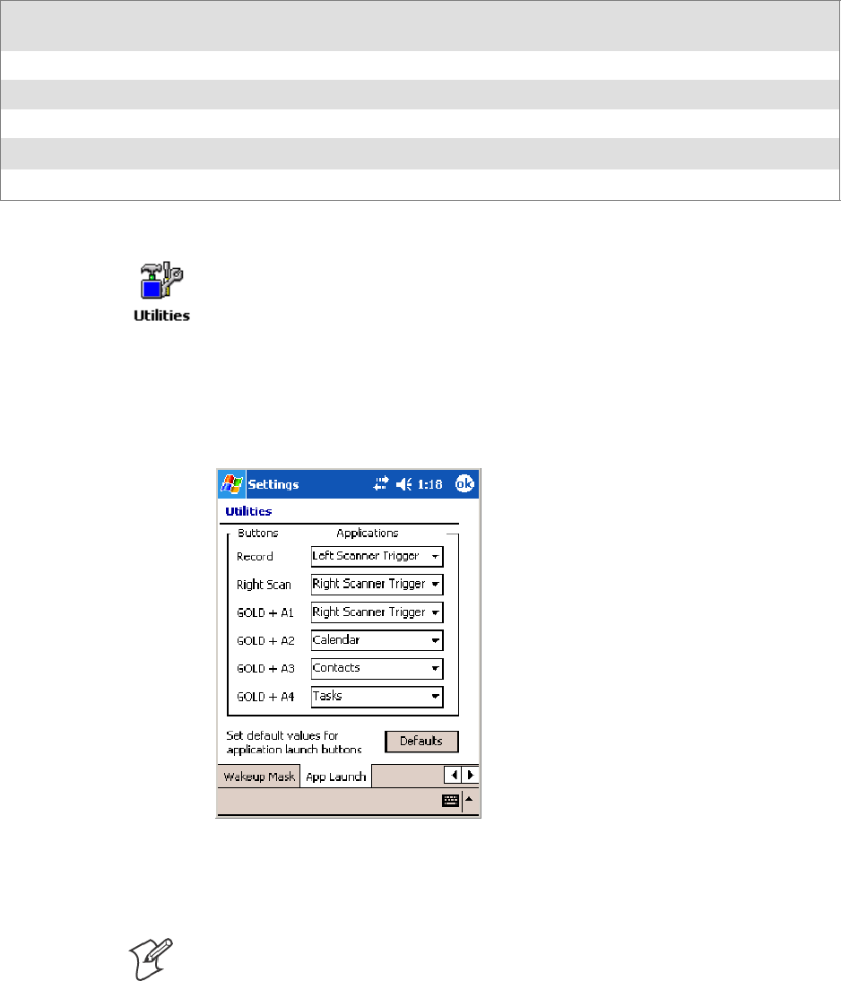
Configurable SettingsAppendix —A
234 700 Series Color Mobile Computer User’s Manual
Based on your setting, do the following to “wake up” the 700 Computer:
If you select:
Then do this on
Numeric Keyboard
Then do this on
Alphanumeric Keyboard
Middle Scanner Button Squeeze the button on the Scan Handle Squeeze the button on the Scan Handle
Left Scanner Button Squeeze the left scanner button Squeeze the left scanner button
Right Scanner Button Squeeze the right scanner button Squeeze the right scanner button
GOLD+A1(Application1) Press [Gold] ba Press [Gold/White] cA
GOLD+A2(Application2) Press [Gold] b4 Press [Gold/White] cB
App Launch
From the 700 Color Computer, tap Start >Settings >theSystem tab >
Utilities , then scroll to the right to tap the App Launch tab to access the
Application Launch applet.
This applet programs or maps two scanner buttons and four application
keys to start up to six applications. Note the left scanner button also acts as
the record button.
For 700 Color Computers with either a laser scanner or an imager,
default mappings are shown in the following illustration.
For 700 Color Computers without either a laser scanner or an imager,
the default maps the Record, Calendar, Contacts, and Tasks applications
the top four and the A3 and A4 buttons are “unassigned” or available for
two more applications.
Note: Record, Calendar, Contacts, and Tasks are Pocket PC applications.
See Chapter 2, “Windows Mobile 2003,” for more information.
STo assign an application to a button, select an application from the ap-
plicable drop-down list box.
STo assign a new application, select the “Add new application” option,
which brings up an Open File dialog and browse Secure Digital or
CompactFlash storage cards for new applications.

Configurable SettingsAppendix —A
235700 Series Color Mobile Computer User’s Manual
STo disable or unmap a currently mapped application from a correspon-
ding button, select “unassigned” from the applicable drop-down list.
STo restore these buttons to their defaults, tap Defaults in the lower
right corner.
Note; You cannot map an application to more than one button. Should
you assign the same application to two buttons, a verification prompt will
appear after the second button to confirm whether you want to remap the
application. If you tap Yes, the applet changes the first button to “unas-
signed” and map the application to the second button.
Note: All changes are activated immediately upon selection.
Wireless Network Applet
Note: See Chapter 4, “Network Support,” for information about the
802.11b or 802.11b/g radio module.
About the Wireless Network
Your wireless adapter (network interface card) connects to wireless net-
works of two types: infrastructure networks and ad-hoc networks.
SInfrastructure networks get you onto your corporate network and the
internet. Your 700 Color Computer establishes a wireless connection to
an access point, which links you to the rest of the network. When you
connect to a network via an access point, you are using the 802.11b or
802.11b/g infrastructure mode.
SAd-hoc networks are private networks shared between two or more cli-
ents, even with no access point.
Each wireless network is assigned a name (or Service Set Identifier —
SSID) to allow multiple networks to coexist in the same area without in-
fringement.
Intermec recommends using security measures with wireless networks to
prevent unauthorized access to your network and to ensure your privacy of
transmitted data. The following are required elements for secure networks:
SAuthentication by both the network and the user
SAuthentication is cryptographically protected
STransmitted data
There are many schemes available for implementing these features.
Terminology
Below and on the next page are terms you may encounter as you configure
your wireless network:
SCKIP (Cisco Key Integrity Protocol)
This is Cisco’s version of the TKIP protocol, compatible with Cisco
Airnet products.

Configurable SettingsAppendix —A
236 700 Series Color Mobile Computer User’s Manual
SEAP (Extensible Authentication Protocol)
802.11b or 802.11b/g uses this protocol to perform authentication.
This is not necessarily an authentication mechanism, but is a common
framework for transporting actual authentication protocols. Intermec
provides a number of EAP protocols to choose for your network.
STKIP (Temporal Key Integrity Protocol)
This protocol is part of the IEEE 802.11i encryption standard for wire-
less LANs., which provides per-packet key mixing, a message integrity
check and a re-keying mechanism, thus overcoming most of the weak
points of WEP. This encryption is more difficult to crack than the stan-
dard WEP. Weak points of WEP include:
SNo Installation Vector (IV) reuse protection
SWeak keys
SNo protection against message replay
SNo detection of message tampering
SNo key updates
SWEP (Wired Equivalent Privacy) encryption
With preconfigured WEP, both the client 700 Color Computer and
access point are assigned the same key, which can encrypt all data be-
tween the two devices. WEP keys also authenticate the 700 Color Com-
puter to the access point — unless the 700 Color Computer can prove
it knows the WEP key, it is not allowed onto the network.
WEP keys are only needed if they are expected by your clients. There
are two types available: 64-bit (5-character strings, 12345) (default) and
128-bit (13-character strings, 1234567890123). Enter these as either
ASCII (12345) or Hex (0x3132333435).
SWPA (Wi-Fi Protected Access)
This is an enhanced version of WEP that does not rely on a static,
shared key. It encompasses a number of security enhancements over
WEP, including improved data encryption via TKIP and 802.11b or
802.11b/g authentication with EAP.
WiFi Alliance security standard is designed to work with existing
802.11 products and to offer forward compatibility with 802.11i.
Configuring Your Wireless Network
To start 802.11b or 802.11b/g communications on the 700 Color
Computer, tap Start >Settings >theSystem tab > Wireless Network to
access the Profile Wizard for the 802.11b or 802.11b/g radio module.
A profile contains all the information necessary to authenticate you to the
network, such as login name, password or certificate, and protocols by
which you are authenticated.
You can have up to four profiles for different networks. For example, you
may have different login names or passwords on different networks, or you
may use a password on one network, and a certificate on another.
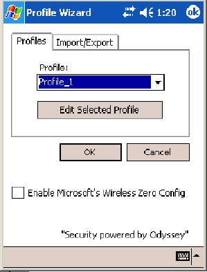
Configurable SettingsAppendix —A
237700 Series Color Mobile Computer User’s Manual
Use the Profiles page to select and configure between the networking envi-
ronments assigned to this 802.11b or 802.11b/g radio.
SProfile:
Tap the drop-down list to choose between four different profiles as-
signed to this unit, then tap Edit Select Profile, make the changes need-
ed for this profile (starting on the next page),thentapOK to return to
the Profiles page.
SEnable Microsoft’s Wireless Zero Config
Check this box to enable Microsoft’s Wireless Zero Config application.
This effectively disables the Intermec software solution for 802.11b or
802.11b/g, including configuration via the Wireless Network applet.
Basic
Use the Basic page to set the network type, name, and manage battery
power for this profile. Tap ok to return to the Profiles page.
SProfile Label:
Enter a unique name for your profile.
SNetwork type:
Tap the drop-down list to select either “Infrastructure” if your network
uses access points to provide connectivity to the corporate network or
internet; or “Ad-Hoc” to set up a private network with one or more par-
ticipants.
SChannel:
If you selected “Ad-Hoc” for the network type, select the channel on
which you are communicating with others in your network. There are
up to 11 channels available.
SSSID (Network Name):
This assumes the profile name unless another name is entered in this field.
If you want to connect to the next available network or are not familiar
with the network name, enter “ANY” in this field. Consult your LAN
administrator for network names.
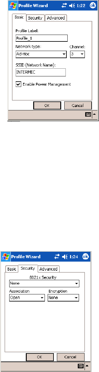
Configurable SettingsAppendix —A
238 700 Series Color Mobile Computer User’s Manual
SEnable Power Management:
Check this box to conserve battery power (default), or clear this box to
disable this feature.
Security
The following are available from the 8021x Security drop-down list. Note
the last four methods are available if you have purchased the security package.
Contact your Intermec representative for information.
SNone (below) STTLS (page 244)
SPEAP (page 240) SLEAP (page 247)
STLS (page 242) SEAP-FAST (page 249)
None
Use “None” to disable 802.11b or 802.11b/g Security and enable either
WEP or WPA-PSK encryption.
To Disable 802.1x Security
Set 8021x Security and Encryption as “None” and Association to “Open.”
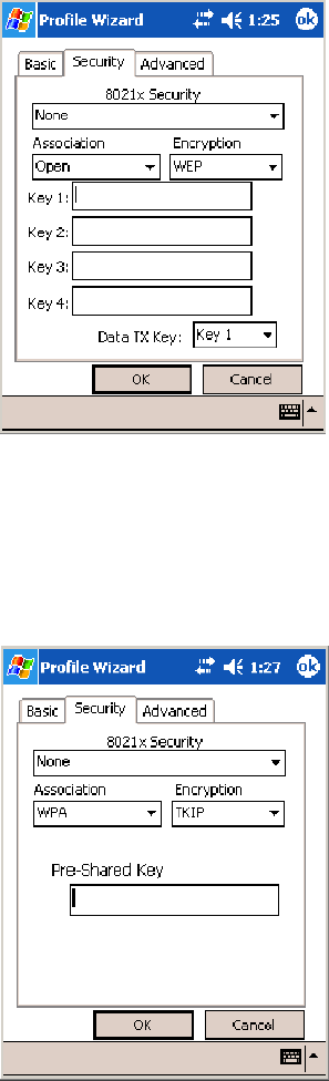
Configurable SettingsAppendix —A
239700 Series Color Mobile Computer User’s Manual
To Enable WEP Encryption
1Set 8021x Security as “None.”
2Set Association to either “Open” if WEP keys are not required; or
“Shared” when WEP keys are required for association.
3Set Encryption to “WEP” (see page 236).
4If you had set Association to “Shared,” then select a data transmission
key from the Data TX Key drop-down list near the bottom of this
screen, then enter the encryption key for that data transmission in the
appropriate Key # field.
To Enable WPA Encryption Using a Preshared Key
1Set 8021x Security as “None.”
2Set Association to “WPA” (see page 236).
3Enter the temporal key as ASCII (12345) in the Pre-Shared Key field.
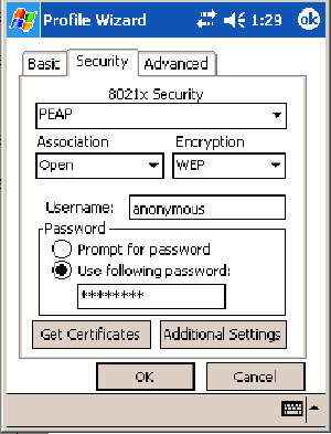
Configurable SettingsAppendix —A
240 700 Series Color Mobile Computer User’s Manual
PEAP (Protected EAP)
This protocol is suitable for performing secure authentication against Win-
dows domains and directory services. It is comparable to EAP-TTLS (see
page 244), both in its method of operation and its security, though not as
flexible. This does not support the range of inside-the-tunnel authentica-
tion methods supported by EAP-TTLS. Microsoft and Cisco both support
this protocol.
Use “PEAP” to configure the use of PEAP as an authentication protocol
and to select “Open,” “WPA,” or “Network EAP” as an association mode.
To Enable PEAP with an Open Association
1Set 8021x Security as “PEAP.”
2Set Association to “Open.”
3Enter your unique user name and password to use this protocol. Select
Prompt for password to have the user enter this password each time to
access the protocol; or leave Use following password as selected to auto-
matically use the protocol without entering a password.
4Tap Get Certificates to obtain or import server certificates (page 247).
5Tap Additional Settings to assign an inner PEAP authentication and set
options for server certificate validation and trust (see page 242).
To Enable PEAP with WPA Encryption
1Set 8021x Security as “PEAP.”
2Set Association to “WPA” (see page 236).
3Enter your unique user name and password to use this protocol. Select
Prompt for password to have the user enter this password each time to
access the protocol, or leave Use following password as selected to auto-
matically use the protocol without entering a password.
4Tap Get Certificates to obtain or import server certificates (page 247).
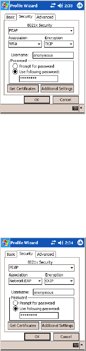
Configurable SettingsAppendix —A
241700 Series Color Mobile Computer User’s Manual
5Tap Additional Settings to assign an inner PEAP authentication and set
options for server certificate validation and trust (see page 242).
To Enable PEAP with Network EAP
1Set 8021x Security as “PEAP.”
2Set Association to “Network EAP” (see page 236).
3Set Encryption to either “WEP” (page 236) or “CKIP” (page 235).
4Enter your unique user name and password to use this protocol. Select
Prompt for password to have the user enter this password each time to
access the protocol, or leave Use following password as selected to auto-
matically use the protocol without entering a password.
5Tap Get Certificates to obtain or import server certificates (page 247).
6Tap Additional Settings to assign an inner PEAP authentication and set
options for server certificate validation (see page 242).
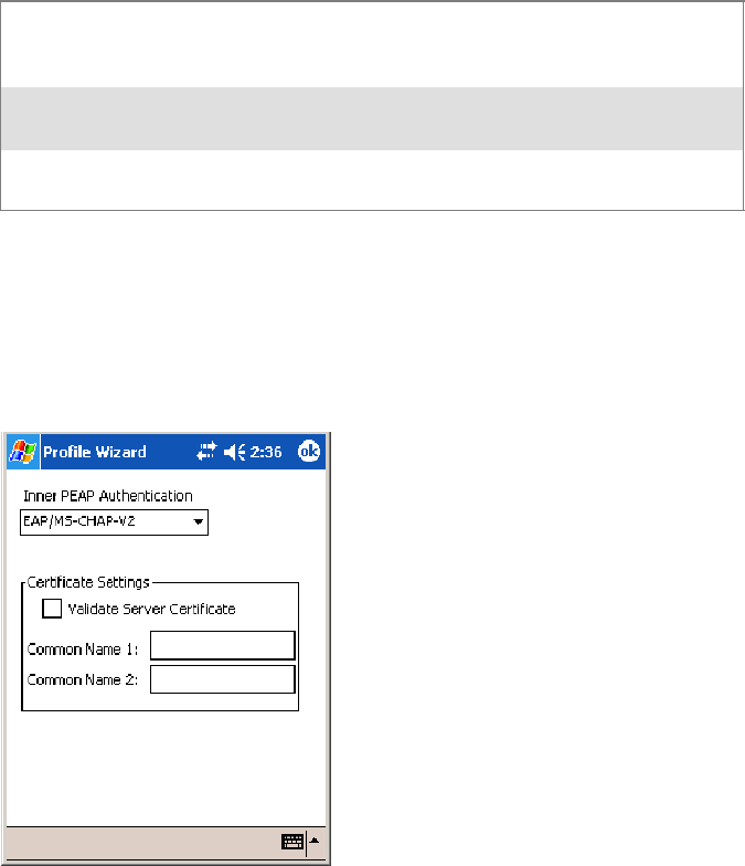
Configurable SettingsAppendix —A
242 700 Series Color Mobile Computer User’s Manual
Additional Settings
1Select an authentication method from the Inner PEAP Authentication
drop-down list.
EAP/MS-CHAP-V2 Authenticates against a Windows Domain Controller and
other non-Windows user databases. This is Microsoft’s
implementation of PEAP.
EAP/Token Card Use with token cards. The password value entered is never
cached. This is Cisco’s implementation of PEAP.
EAP/MD5-Challenge Message Digest 5. A secure hashing authentication algo-
rithm.
2Check Validate Server Certificate to verify the identity of the authenti-
cation server based on its certificate when using TTLS or PEAP.
3Enter the Common Names of trusted servers. Note if these fields are left
blank, the server certificate trust validation is not performed or required.
4Click ok to return to the Security page.
TLS (EAP-TLS)
EAP-TLS is a protocol that is based on the TLS (Transport Layer Security)
protocol widely used to secure web sites. This requires both the user and
authentication server have certificates for mutual authentication. While
cryptically strong, this requires corporations that deploy this to maintain a
certificate infrastructure for all their users.
Use “TLS” to configure the use of EAP-TLS as an authentication protocol,
and select either “Open” or “WPA” as an association mode.
ToEnableTLSwithanOpenAssociation
1Set 8021x Security as “TLS.”
2Set Association to “Open.”
3EnteryouruniqueSubject Name and User Name to use this protocol.
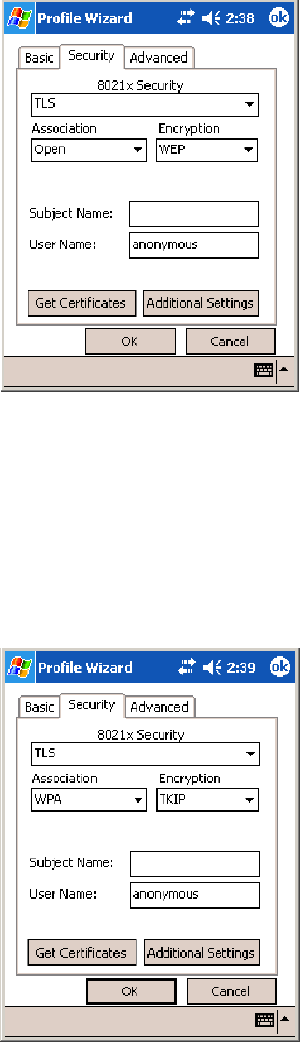
Configurable SettingsAppendix —A
243700 Series Color Mobile Computer User’s Manual
4Tap Get Certificates to obtain or import server certificates (page 247).
5Tap Additional Settings to set server certificate validation (page 244).
To Enable TLS with WPA Encryption
1Set 8021x Security as “TLS.”
2Set Association to “WPA” (see page 236).
3Enter unique Subject Name and User Name credentials for this profile.
4Tap Get Certificates to obtain or import server certificates (page 247).
5Tap Additional Settings to set server certificate validation (page 244).

Configurable SettingsAppendix —A
244 700 Series Color Mobile Computer User’s Manual
Additional Settings
1Check Validate Server Certificate to verify the identity of the authenti-
cation server based on its certificate when using PEAP or TLS.
2Enter the Common Names of trusted servers. Note that if these fields are
left blank, the server certificate trust validation is not performed or required.
3Click ok to return to the Security page.
TTLS (EAP-Tunneled TLS)
This protocol provides authentication like EAP-TLS (see page 242) but
does not require certificates for every user. Instead, authentication servers
are issued certificates. User authentication is done using a password or oth-
er credentials that are transported in a securely encrypted “tunnel” estab-
lished using server certificates.
EAP-TTLS works by creating a secure, encrypted tunnel through which
you present your credentials to the authentication server. Thus, inside
EAP-TTLS there is another inner authentication protocol that you must
configure via Additional Settings.
Use “TTLS” to configure the use of EAP-TTLS as an authentication pro-
tocol, and select either “Open” or “WPA” as an association mode.
ToEnableTTLSwithanOpenAssociation(default configuration)
1Set 8021x Security as “TTLS.”
2Set Association to “Open.”
3Enter your unique user name and password to use this protocol. Select
Prompt for password to have the user enter this password each time to
access the protocol, or leave Use following password as selected to auto-
matically use the protocol without entering a password.
4Tap Get Certificates to obtain or import server certificates (page 247).
5Tap Additional Settings to assign an inner TTLS authentication and an
inner EAP, and set server certificate validation and trust (page 246).
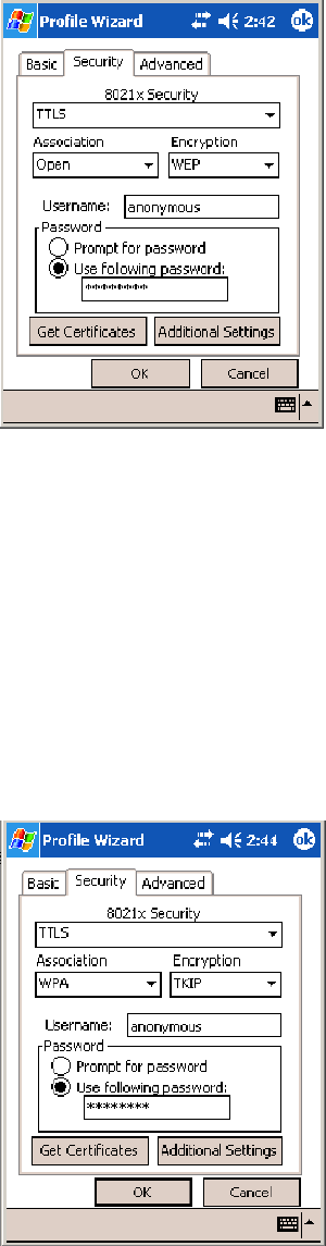
Configurable SettingsAppendix —A
245700 Series Color Mobile Computer User’s Manual
To Enable TTLS with WPA Encryption
1Set 8021x Security as “TTLS.”
2Set Association to “WPA” (see page 236).
3Enter your unique user name and password to use this protocol. Select
Prompt for password to have the user enter this password each time to
access the protocol, or leave Use following password as selected to auto-
matically use the protocol without entering a password.
4Tap Get Certificates to obtain or import server certificates (page 247).
5Tap Additional Settings to assign an inner TTLS authentication and an
inner EAP, and set server certificate validation and trust (see page 246).
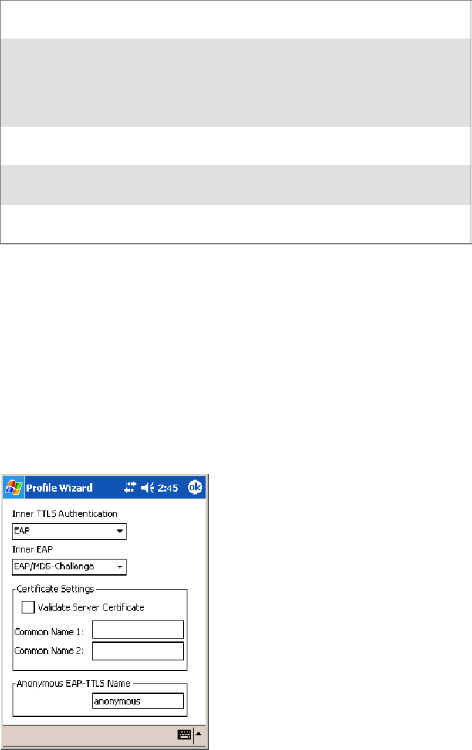
Configurable SettingsAppendix —A
246 700 Series Color Mobile Computer User’s Manual
Additional Settings
1Select an authentication protocol from the Inner TTLS Authentication
drop-down list:
PAP Password Authentication Protocol. A simple authentication
protocol that sends security information in the clear.
CHAP Challenge Handshake Authentication Protocol. Use of Radius
to authenticate a terminal without sending security data in the
clear. Authenticates against non-Windows user databases. You
cannot use this if authenticating against a Windows NT Domain
or Active Directory.
MS-CHAP;
MS-CHAP-V2
Authenticates against a Windows Domain Controller and other
non-Windows user databases.
PAP/Token Card Use with token cards. The password value entered is never
cached.
EAP Extensible Authentication Protocol. See page 236 for informa-
tion about EAP.
2If you select “EAP” for the inner authentication protocol, then select an
inner EAP protocol from the Inner EAP drop-down list.
3Enter the Common Names of trusted servers. Note that if these fields are
left blank, the server certificate trust validation is not performed or required.
4Check Validate Server Certificate to verify the identity of the authenti-
cation server based on its certificate when using TTLS, PEAP, and TLS.
5Enter the Anonymous EAP-TTLS Name as assigned for public usage.
Use of this outer identity protects your login name or identity.
6Click ok to return to the Security page.

Configurable SettingsAppendix —A
247700 Series Color Mobile Computer User’s Manual
To Get Certificates
Certificates are pieces of cryptographic data that guarantee a public key is
associated with a private key. They contain a public key and the entity
name that owns the key. Each certificate is issued by a certificate authority.
Use this page to import a certificate onto the 700 Color Computer.
Root Certificates
1Tap the <<< button next to the Import Root Certificate field to select
the root certificate (DER-encoded .CER file) to import.
2Click Import Root Cert to install the selected certificate.
User Certificate
1Tap the <<< button next to the Certificate Path field to select the user
certificate (DER-encoded .CER file without the private key) to import.
2Tap the <<< button next to the Key Path field to select the private key
(.PVK file) which corresponds to the user certificate chosen in step 1.
3Tap Import User Cert to install the selected certificate.
Web Enrollment
Tap Web Enrollment to obtain a user certificate over the network from an
IAS Server. Tap ok to return to the Security page.
LEAP (Cisco Lightweight EAP)
LEAP is the Cisco Lightweight version of EAP. See page 236 for informa-
tion about EAP.
Use “LEAP” to configure the use of LEAP as an authentication protocol,
select “Open,” “WPA,” or “Network EAP” as an association mode. Note
this defaults to the Network EAP.
To Enable LEAP with an Open Association
1Set 8021x Security as “LEAP” and Association to “Open.”
2EnteryouruniqueUser Name to use this protocol.
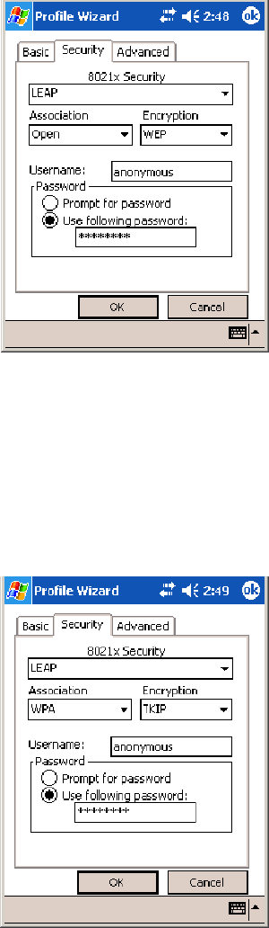
Configurable SettingsAppendix —A
248 700 Series Color Mobile Computer User’s Manual
3Select Prompt for password to have the user enter this password each
time to access the protocol, or leave Use following password as selected
to automatically use the protocol without entering a password.
To Enable LEAP with WPA Encryption
1Set 8021x Security as “LEAP” and Association to “WPA” (see page
236).
2EnteryouruniqueUser Name to use this protocol.
3Select Prompt for password to have the user enter this password each
time to access the protocol, or leave Use following password as selected
to automatically use the protocol without entering a password.
To Enable LEAP with Network EAP
1Set 8021x Security as “LEAP,” Association to “Network EAP” (see page
236), and Encryption to either “WEP” (page 236) or “CKIP” (page
235).
2EnteryouruniqueUser Name to use this protocol.

Configurable SettingsAppendix —A
249700 Series Color Mobile Computer User’s Manual
3Select Prompt for password to have the user enter this password each
time to access the protocol, or leave Use following password as selected
to automatically use the protocol without entering a password.
EAP-FAST (EAP -Flexible Authentication via Secured Tunnel)
The EAP-FAST protocol is a client-server security architecture that en-
crypts EAP transactions with a TLS tunnel. While similar to PEAP, it dif-
fers significantly as EAP-FAST tunnel establishment is based on strong se-
crets unique to users. These secrets are called Protected Access Credentials
(PACs), which CiscoSecure ACS generates using a master key known only
to CiscoSecure ACS. Because handshakes based upon shared secrets are
intrinsically faster than handshakes based upon PKI, EAP-FAST is the sig-
nificantly faster of the two solutions that provide encrypted EAP transac-
tions. No certificate management is required to implement EAP-FAST.
Use “EAP-FAST” to configure the use of EAP-FAST as an authentication
protocol, select “Open,” “WPA,” or “Network EAP” as an association
mode. Note this defaults to the Network EAP.
To Enable EAP-FAST with an Open Association
1Set 8021x Security as “EAP-FAST” and Association to “Open.”
2EnteryouruniqueUsername to use this protocol.
3Select Prompt for password to have the user enter this password each
time to access the protocol, or leave Use following password as selected
to automatically use the protocol without entering a password.
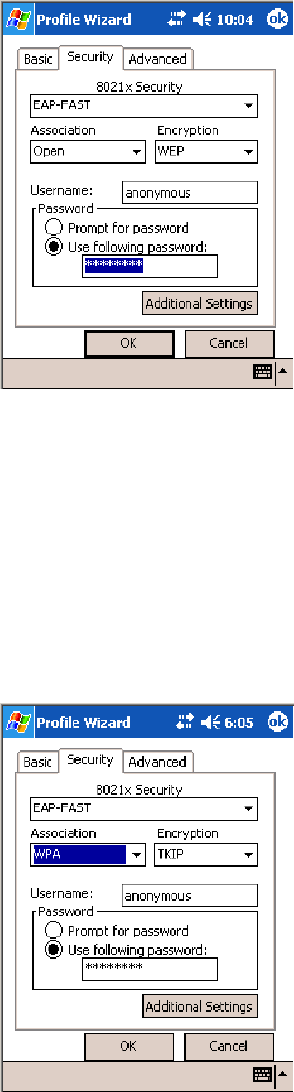
Configurable SettingsAppendix —A
250 700 Series Color Mobile Computer User’s Manual
4Tap Additional Settings to set options for PAC management and assign
an anonymous EAP-FAST name (see page 251).
To Enable EAP-FAST with WPA Encryption
1Set 8021x Security as “EAP-FAST” and Association to “WPA” (see
page 236).
2EnteryouruniqueUsername to use this protocol.
3Select Prompt for password to have the user enter this password each
time to access the protocol, or leave Use following password as selected
to automatically use the protocol without entering a password.
4Tap Additional Settings to set options for PAC management and assign
an anonymous EAP-FAST name (see page 251).
To Enable EAP-FAST with Network EAP
1Set 8021x Security as “EAP-FAST,” Association to “Network EAP”
(page 236), and Encryption to either “WEP”(page 236) or “CKIP”
(page 235).
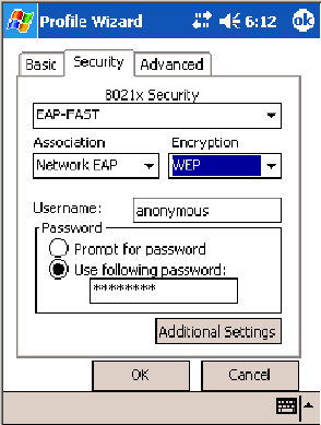
Configurable SettingsAppendix —A
251700 Series Color Mobile Computer User’s Manual
2EnteryouruniqueUsername to use this protocol.
3Select Prompt for password to have the user enter this password each
time to access the protocol, or leave Use following password as selected
to automatically use the protocol without entering a password.
4Tap Additional Settings to set options for PAC management and assign
an anonymous EAP-FAST name. See below for more information.
Additional Settings
1Tap PAC Manager to view the PAC files currently installed on your
700 Color Computer. Tap ok to return to the Additional Settings
screen.
2If you already have a PAC on your 700 Color Computer, clear Allow
Automatic PAC provisioning to avoid receiving additional PACs from
the server.
3If Allow Automatic PAC provisioning is checked, you can check:
SPrompt before acquiring a new PAC for notification of any incom-
ing PACs.
SPrompt before replacing a PAC for notification whether to replace a
current PAC with an incoming PAC.
4Enter the Anonymous EAP-FAST Name as assigned for public usage.
This outer identity protects your login name or identity.
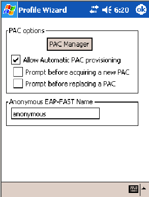
Configurable SettingsAppendix —A
252 700 Series Color Mobile Computer User’s Manual
5Check ok to return to the Security page.
Advanced
Use this page to configure additional settings for this profile. Tap ok or
OK to return to the Profiles page.
SDetect Rogue APs:
Wireless NICs and APs associate based on the SSID configured for the
NIC. Given an SSID, the BSSID with the strongest signal is often cho-
sen for association. After association, 802.1x authentication may occur
and during authentication credentials to uniquely identify a user —
these are passed between the NIC and the AP.
The base 802.1x technology does not protect the network from “rogue
APs.” These can mimic a legitimate AP to authentication protocols and
user credentials. This provides illegal users ways to mimic legitimate us-
ers and steal network resources and compromise security.
Check this box to detect and report client behavior suspected of being
rogue APs. Once a rouge AP is detected, your 700 Series Computer no
longer associates with that AP until you perform a warm boot.
Clear this box to solve AP connection problems that result when an AP
gets put on the rogue AP list due to inadvertent failed authentications
and not because it is a real rouge.
SEnable mixed cell:
Mixed cell is a profile-dependent setting. If enabled, you can connect to
mixed cell without using WEP, then you can query the cell to deter-
mine whether you can use encryption.
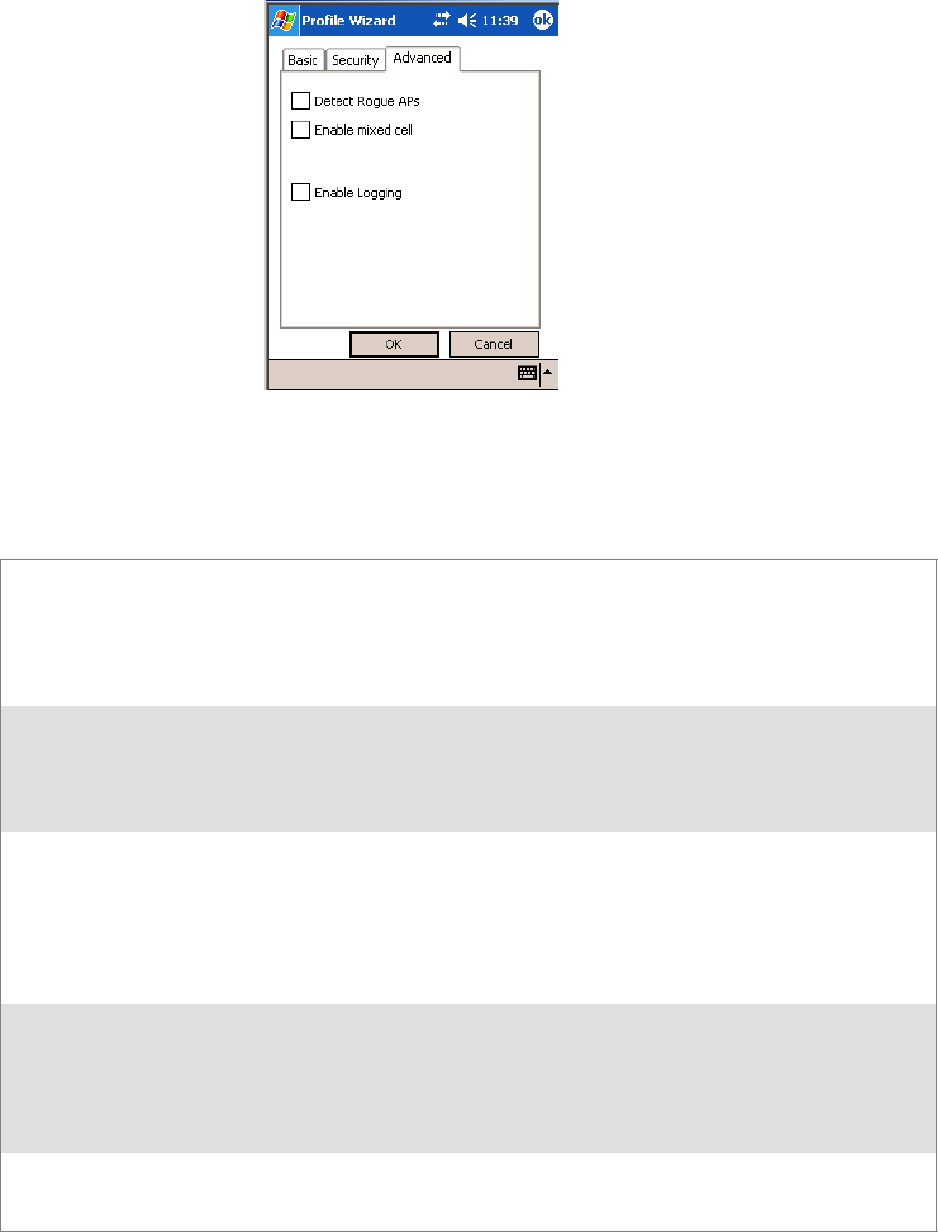
Configurable SettingsAppendix —A
253700 Series Color Mobile Computer User’s Manual
SEnable Logging:
Check this box to log what activity incurs for this profile.
Other Configurable Parameters
These can be configured by sending reader commands (next page) through
the network or from an application.
Audio Volume Changes the volume of all audio signals. 0Off
1 Very quiet
2Quiet
3Normal(default)
4Loud
5Veryloud
Automatic Shutoff Setsthelengthoftimethe700ColorComputerre-
mains on when there is no activity. When you turn on
the 700 Color Computer, it either resumes exactly
where it was when you turned it off or boots and restarts
your application.
11minute
22minutes
3 3 minutes (default)
44minutes
55minutes
Backlight Timeout Sets the length of time that the display backlight re-
mains on. If you set a longer timeout value, you use the
battery power at a faster rate.
10 10 seconds
30 30 seconds
60 1 minute (default)
120 2 minutes
180 3 minutes
240 4 minutes
300 5 minutes
Date/Time Sets the current date and time. Date Year 0000–9999 (1999)
Month 1–12 (6)
Day 1–31 (1)
Time Hour 0–23 (0)
Minute 0–59 (00)
Second 0–59 (00)
Key Clicks Enables or disables the keypad clicks. The 700 Color
Computer emits a click each time you press a key or
decode a row of a two-dimensional symbology.
0 Disable clicks
1Enablesoftkeyclicks
2 Enable loud key clicks (default)

Configurable SettingsAppendix —A
254 700 Series Color Mobile Computer User’s Manual
Using Reader Commands
After the 700 Color Computer is connected to your network, you can
send the 700 Color Computer a reader command from an application to
perform a task, such as changing the time and date. Some reader com-
mands temporarily override the configuration settings and some change
the configuration settings.
Change Configuration
The Change Configuration command must precede any configuration
command. If you enter a valid string, the 700 Color Computer configura-
tion is modified and the computer emits a high beep. To send the Change
Configuration command through the network, use the $+ [command]
syntax where command is the two-letter command syntax for the configu-
ration command followed by the value to be set for that command.
You can also make changes to several different commands by using the
$+ [command]...[command n] syntax. There are seven configuration
command settings that can be changed in this way. See each command for
information on respective acceptable “data” values.
Command Syntax
Audio Volume BVdata
Automatic Shutoff EZdata
Backlight Timeout DFdata
Key Clicks KCdata
Virtual Wedge Grid AFdata
Virtual Wedge Postamble AEdata
Virtual Wedge Preamble ADdata
Example 1
To change the Beep Volume to Off, you can send this string to the 700
Color Computer through the network: $+BV0
where:
$+ Indicates Change Configuration.
BV Specifies the Audio Volume parameter.
0Specifies a value of Off.
Example 2
To change the Beep Volume to Very Quiet and the Virtual Wedge Grid
to 123: $+BV1AF123
where:
$+ Indicates Change Configuration
BV1 Specifies Audio Volume, set to Very Quiet (1)
AF123 Specifies Virtual Wedge Grid, set to a value of 123.
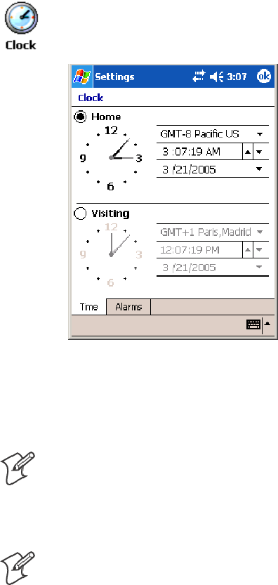
Configurable SettingsAppendix —A
255700 Series Color Mobile Computer User’s Manual
Set Time and Date
This command sets the date and time on the 700 Color Computer. The
default date and time is June 1, 1999 at 12:00 AM.
From the network, send the following:
/+ yyyymmddhhmmss
whereacceptablevaluesforthedateare:
yyyy 0000–9999 Year
mm 01–12 Month of the year
dd 01–31 Day of the month
hh 00–23 Hour
mm 00–59 Minutes
ss 00–59 Seconds
You can also set the time and date by using Configuration Management in
Unit Manager, or by using the Clock applet in the Settings menu. To
access this applet, tap Start >Settings >theSystem tab>theClock icon.
Configuration Bar Codes
You can change some settings on your 700 Color Computer by scanning
the following Code 39 bar code labels.
Note: When you use a bar code creation utility to make a scannable bar
code label, the utility probably adds opening and closing asterisks automat-
ically. Asterisks are included here for translation purposes.
Audio Volume
Note: The Audio Volume parameter information is on page 253.
Turn Audio Off
*$+BV0*
*$+BV0*

Configurable SettingsAppendix —A
256 700 Series Color Mobile Computer User’s Manual
Set Audio Volume to very quiet
*$+BV1*
*$+VB1*
Set Audio Volume to quiet
*$+BV2*
*$+BV2*
Set Audio Volume to normal (default)
*$+BV3*
*$+BV3*
Set Audio Volume to loud
*$+BV4*
*$+BV4*
Set Audio Volume to very loud
*$+BV5*
*$+BV5*
Automatic Shutoff
Note: The Automatic Shutoff parameter information is on page 253.
Set Automatic Shutoff to 1 minute
*$+EZ1*
*$+EZ1*
Set Automatic Shutoff to 2 minutes
*$+EZ2*
*$+EZ2*
Set Automatic Shutoff to 3 minutes (default)
*$+EZ3*
*$+EZ3*
Set Automatic Shutoff to 4 minutes
*$+EZ4*
*$+EZ4*
Set Automatic Shutoff to 5 minutes
*$+EZ5*
*$+EZ5*
Backlight Timeout
Note: The Backlight Timeout parameter information is on page 253.
Backlight Timeout 10 seconds
*$+DF10*
*$+DF10*

Configurable SettingsAppendix —A
257700 Series Color Mobile Computer User’s Manual
Backlight Timeout 30 seconds
*$+DF30*
*$+DF30*
Backlight Timeout 1 minute (default)
*$+DF60*
*$+DF60*
Backlight Timeout 2 minutes
*$+DF120*
*$+DF120*
Backlight Timeout 3 minutes
*$+DF180*
*$+DF180*
Backlight Timeout 4 minutes
*$+DF240*
*$+DF240*
Backlight Timeout 5 minutes
*$+DF300*
*$+DF300*
Key Clicks
Note: The Key Clicks parameter information is on page 253.
Disable key clicks
*$+KC0*
*$+KC0*
Enable soft key clicks
*$+KC1*
*$+KC1*
Enable loud key clicks (default)
*$+KC2*
*$+KC2*
Virtual Wedge Grid, Preamble, Postamble
The following parameters are user-configurable strings. Refer to a full
ASCII chart for more information.
Grid
For Virtual Wedge Grid, the first part of the bar code is the following,
which can include a string of up to 240 characters.
*$+AF
*$+AF
Configurable SettingsAppendix —A
258 700 Series Color Mobile Computer User’s Manual
Preamble
For Virtual Wedge Preamble, the first part of the bar code is below, fol-
lowed by a string of up to 31 characters (no <NUL>) and an asterisk. De-
fault is no characters.
*$+AD
*$+AD
Postamble
For Virtual Wedge Postamble, the first part of the bar code is below, fol-
lowed by a string of up to 31 characters (no <NUL>) and an asterisk. De-
fault is no characters.
*$+AE
*$+AE

259700 Series Color Mobile Computer User’s Manual
Troubleshooting
B
This appendix contains a brief explanation of what you can do to trouble-
shoot your 700 Color Mobile Computer.

TroubleshootingAppendix —B
260 700 Series Color Mobile Computer User’s Manual
Problem Solutions
The 700 Color Computer does not respond when con-
nected to a power supply.
Make sure your ac adapter or dock is plugged in and is
making good contact with your mobile computer.
The 700 Color Computer will not turn on when the I/O
key is pressed.
The AB10 battery may be low and need recharging.
The Power status LED starts blinking. The Power status LED provides the status of your bat-
tery pack when it is connected to a charging device. See
Chapter 1, “Introduction,” for LED descriptions.
The 700 Color Computer will not turn on and the
screen is blank.
The battery may be critically low. Put your mobile com-
puterinanAD15orAD18chargerforatleastfivemin-
utes, remove it from the dock, then press the I/O button.
The screen should turn on.
Put your mobile computer back in the charger and con-
tinue to charge your mobile computer for at least four
hours to make sure the battery is fully charged.
The 700 Color Computer will not turn on when placed
in a dock.
Make sure the dock is plugged in and your mobile com-
puter is securely seated in the dock.
The700ColorComputershutsdownduringoperation. You may have a very low battery. Put the battery in an
AC15 or AC16 charger.
The 700 Color Computer does not turn off. The 700 Color Computer does not turn off while it is
processing data. If this situation continues for a long
period of time, it does run down the battery unless you
have it connected to an external power, or in a charging
dock.
Should the 700 Color Computer lock up, perform a
warm-boot. If the mobile computer stays locked up, then
perform a cold-boot. See Chapter 1, “Introduction,” for
information on performing warm-boots and cold-boots.
The 700 Color Computer takes a long time to boot up
after a warm- or cold-boot is performed.
Normal recovery time is 30 to 45 seconds. If the recovery
takes longer, then contact support personnel.

261700 Series Color Mobile Computer User’s Manual
Index
I
The Classes and Functions Index covers 700 Color classes and functions.
The General Index covers all topics. Those in italics are figures, those in bold are
tables.
The Files Index is to assist you in locating descriptions for device drivers, applica-
tions, utilities, batch files, or other files within this publication.
Index
262 700 Series Color Mobile Computer User’s Manual
Classes and Functions
A
add_registry_section, [AddReg]
flags, 194
registry_root_string, 194
value_name, 194
AddReg, [DefaultInstall], 191
[AddReg], add_registry_section
flags, 194
registry_root_string, 194
value_name, 194
AppName, [CEStrings], 189
Asset management, DeviceURL parameter, 204
B
BlockSize, FTP Server, 204
BuildMax, [CEDevice], 190
BuildMin, [CEDevice], 190
C
[CEDevice]
BuildMax, 190
BuildMin, 190
ProcessorType, 189
UnsupportedPlatforms, 189
VersionMax, 190
VersionMin, 190
CESelfRegister, [DefaultInstall], 191
CESetupDLL, [DefaultInstall], 191
CEShortcuts, [DefaultInstall], 191
[CEShortcuts], shortcut_list_section
shortcut_filename, 194
shortcut_type_flag, 194
target_file/path, 195
target_file_path, 195
CESignature
[SourceDiskNames], 191
[Version], 188
[CEStrings]
AppName, 189
InstallDir, 189
ClassID field values
VN_CLASS_ASIC, 212
VN_CLASS_BOOTSTRAP, 212
VN_CLASS_KBD, 212
CloseHandle()
DTR printing, 167, 168
IrDA printing, 162
NPCP printing, 163, 164
Cold boot, IOCTL_HAL_COLDBOOT, 217
Copyfiles, [DefaultInstall], 191
[CopyFiles], file_list_section
destination_filename, 193
flags, 193
source_filename, 193
CreateEvent(), 225
CreateFile()
DTR printing, 167
IrDA printing, 162
NPCP printing, 163, 164
D
[DefaultInstall]
AddReg, 191
CESelfRegister, 191
CESetupDLL, 191
CEShortcuts, 191
Copyfiles, 191
DeregisterDevice(), 163
DTR printing, 167
[DestinationDirs], file_list_section, 192
DeviceIOControl()
DTR printing, 167
NPCP printing, 163
DeviceIoControl(), NPCP printing, 164
DeviceName,FTPServer,204
DeviceURL, FTP Server, 204
disk_ordinal, [SourceDiskNames], 191
DllRegisterServer, 191
DllUnregisterServer, 191
E
ERROR_INSUFFICIENT_BUFFER
IOCTL_HAL_ITC_READ_PARM, 211
IOCTL_HAL_ITC_WRITE_SYSPARM, 214
ERROR_INVALID_PARAMETER
IOCTL_HAL_ITC_READ_PARM, 211
IOCTL_HAL_ITC_WRITE_SYSPARM, 214
F
File Transfer Protocol. See FTP
file_list_section
[CopyFiles]
destination_filename, 193
flags, 193
source_filename, 193
[DestinationDirs], 192
filename, [SourceDiskFiles], 192
FTP
client, 205
configurable parameters, 204
BlockSize, 204
DeviceName, 204
DeviceURL, 204
PauseAtStartup, 205
FTPDCMDS subdirectory, 208
RTC 959, 208
server, 205
server requests
CDUP, 205
CWD, 205
DELE, 206
HELP, 206
LIST, 206
MKD, 206
MODE, 206
NLST, 206
NOOP, 206
PASS, 206
PWD, 206
Index
263700 Series Color Mobile Computer User’s Manual
QUIT, 206
RETR, 206
RMD, 206
RNFR, 206
RNTO, 206
SITE, 206
SITE ATTRIB, 206
SITE BOOT, 207
SITE COPY, 207
SITE EKEY, 207
SITE EVAL, 207
SITE EXIT, 207
SITE GVAL, 208
SITE HELP, 207
SITE KILL, 207
SITE LOG, 207
SITE PLIST, 207
SITE PVAL, 208
SITE RUN, 207
SITE STATUS, 207
SITE TIMEOUT, 207
STOR, 206
SYST, 206
TYPE, 206
USER, 206
XCUP, 206
XCWD, 206
XMKD, 206
XPWD, 206
XRMD, 206
stopping server from application, 208
support, 205
web browsers, 208
H
HAL, verion of Pocket PC
IOCTL_HAL_GET_BOOTLOADER_VERINFO,
216
IOCTL_HAL_GET_OAL_VERINFO, 216
I
ID field values
IOCTL_HAL_ITC_READ_PARM
ITC_NVPARM_80211_INSTALLED, 213
ITC_NVPARM_80211_RADIOTYPE, 213
ITC_NVPARM_ANTENNA_DIVERSITY, 212
ITC_NVPARM_BLUETOOTH_INSTALLED,
213
ITC_NVPARM_CONTRAST, 212
ITC_NVPARM_DISPLAY_TYPE, 212
ITC_NVPARM_ECN, 212
ITC_NVPARM_EDBG_SUBNET, 212
ITC_NVPARM_EDG_IP, 212
ITC_NVPARM_ETHERNET_ID, 212
ITC_NVPARM_INTERMEC_DATACOLLEC-
TION_HW, 213
ITC_NVPARM_INTERMEC_DATACOLLEC-
TION_SW, 212
ITC_NVPARM_INTERMEC_SOFT-
WARE_CONTENT, 212
ITC_NVPARM_LAN9000_INSTALLED, 213
ITC_NVPARM_MANF_DATE, 212
ITC_NVPARM_MCODE, 212
ITC_NVPARM_RTC_RESTORE, 212
ITC_NVPARM_SERIAL_NUM, 212
ITC_NVPARM_SERIAL2_INSTALLED, 213
ITC_NVPARM_SERVICE_DATE, 212
ITC_NVPARM_SIM_PRO-
TECT_HW_INSTALLED, 213
ITC_NVPARM_SIM_PRO-
TECT_SW_INSTALLED, 213
ITC_NVPARM_VERSION_NUMBER, 212
ITC_NVPARM_VIBRATE_INSTALLED, 213
ITC_NVPARM_WAN_FREQUENCY, 213
ITC_NVPARM_WAN_INSTALLED, 213
ITC_NVPARM_WAN_RADIOTYPE, 213
ITC_NVPARM_WAN_RI, 212
IOCTL_HAL_ITC_WRITE_SYSPARM
ITC_ DOCK_SWITCH, 214
ITC_ WAKEUP_MASK, 215
ITC_AMBIENT_FRONTLIGHT, 215
ITC_AMBIENT_KEYBOARD, 215
ITC_REGISTRY_SAVE_ENABLE, 214
IDNA
DeviceName, 204
DeviceURL, 204
IDNATarget, FTP Server, 204
InstallDir, [CEStrings], 189
Intermec Device Network Announcement. See IDNA
IOCTL_GET_CPU_ID, 220
IOCTL_HAL_COLDBOOT, 217, 222
IOCTL_HAL_GET_BOOT_DEVICE, 219
IOCTL_HAL_GET_BOOTLOADER_VERINFO, 216
IOCTL_HAL_GET_DEVICE_INFO, 210
IOCTL_HAL_GET_DEVICEID, 215
IOCTL_HAL_GET_OAL_VERINFO, 216
IOCTL_HAL_GET_RESET_INFO, 218
IOCTL_HAL_ITC_READ_PARM, 211
IOCTL_HAL_ITC_WRITE_SYSPARM, 214
IOCTL_HAL_REBOOT, 219, 222
IOCTL_HAL_WARMBOOT, 217, 222
IOCTL_PROCESSOR_INFORMATION, 220
ITC_ DOCK_SWITCH, 214
ITC_ WAKEUP_MASK, 215
ITC_AMBIENT_FRONTLIGHT, 215
ITC_AMBIENT_KEYBOARD, 215
ITC_DEVID_80211RADIO_INTEL_2011B, 213
ITC_DEVID_80211RADIO_MAX values
ITC_DEVID_80211RADIO_INTEL_2011B, 213
ITC_DEVID_80211RADIO_NONE, 213
ITC_DEVID_80211RADIO_NONE, 213
ITC_DEVID_INTERMEC_EVIO, 213
ITC_DEVID_INTERMEC2D_IMAGER, 213
ITC_DEVID_OEM2D_IMAGER, 213
Index
264 700 Series Color Mobile Computer User’s Manual
ITC_DEVID_SCANHW_MAX values
ITC_DEVID_INTERMEC_EVIO, 213
ITC_DEVID_INTERMEC2D_IMAGER, 213
ITC_DEVID_OEM2D_IMAGER, 213
ITC_DEVID_SCANHW_NONE, 213
ITC_DEVID_SE900_LASER, 213
ITC_DEVID_SE900HS_LASER, 213
ITC_DEVID_SCANHW_NONE, 213
ITC_DEVID_SE900_LASER, 213
ITC_DEVID_SE900HS_LASER, 213
ITC_DEVID_WANRADIO_NONE, 213
ITC_DEVID_WANRADIO_SIEMENS_MC45, 213
ITC_DEVID_WANRADIO_SIEMENS_MC46, 213
ITC_DEVID_WANRADIO_SIERRA_SB555, 213
ITC_DEVID_WANRADIO_XIRCOM_GEM3503, 213
ITC_IFTP_STOP, 208
ITC_NVPARM_80211_INSTALLED, 213
ITC_NVPARM_80211_RADIOTYPE, 213
ITC_NVPARM_ANTENNA_DIVERSITY, 212
ITC_NVPARM_BLUETOOTH_INSTALLED, 213
ITC_NVPARM_CONTRAST, 212
ITC_NVPARM_DISPLAY_TYPE, 212
ITC_NVPARM_ECN, 212
ITC_NVPARM_EDBG_SUBNET, 212
ITC_NVPARM_EDG_IP, 212
ITC_NVPARM_ETHERNET_ID, 212
ITC_NVPARM_INTERMEC_DATACOLLEC-
TION_HW, 213
ITC_NVPARM_INTERMEC_DATACOLLEC-
TION_SW, 212
ITC_NVPARM_INTERMEC_SOFTWARE_CON-
TENT, 212
ITC_NVPARM_LAN9000_INSTALLED, 213
ITC_NVPARM_MANF_DATE, 212
ITC_NVPARM_MCODE, 212
ITC_NVPARM_RTC_RESTORE, 212
ITC_NVPARM_SERIAL_NUM, 212
ITC_NVPARM_SERIAL2_INSTALLED, 213
ITC_NVPARM_SERVICE_DATE, 212
ITC_NVPARM_SIM_PROTECT_HW_INSTALLED,
213
ITC_NVPARM_SIM_PROTECT_SW_INSTALLED,
213
ITC_NVPARM_VERSION_NUMBER, 212
ITC_NVPARM_VIBRATE_INSTALLED, 213
ITC_NVPARM_WAN_FREQUENCY, 213
ITC_NVPARM_WAN_INSTALLED, 213
ITC_NVPARM_WAN_RADIOTYPE, 213
ITC_NVPARM_WAN_RI, 212
ITC_REGISTRY_SAVE_ENABLE, 214
K
KernelIoControl
IOCTL_GET_CPU_ID, 220
IOCTL_HAL_COLDBOOT, 217, 222
IOCTL_HAL_GET_BOOT_DEVICE, 219
IOCTL_HAL_GET_BOOTLOADER_VERINFO,
216
IOCTL_HAL_GET_DEVICE_INFO, 210
IOCTL_HAL_GET_DEVICEID, 215
IOCTL_HAL_GET_OAL_VERINFO, 216
IOCTL_HAL_GET_RESET_INFO, 218
IOCTL_HAL_ITC_READ_PARM, 211
IOCTL_HAL_ITC_WRITE_SYSPARM, 214
IOCTL_HAL_REBOOT, 219, 222
IOCTL_HAL_WARMBOOT, 217, 222
IOCTL_PROCESSOR_INFORMATION, 220
KernelIoControl(), 210
L
lpBytesReturned
IOCTL_GET_CPU_ID, 221
IOCTL_HAL_GET_BOOT_DEVICE, 219
IOCTL_HAL_GET_BOOTLOADER_VERINFO,
217
IOCTL_HAL_GET_DEVICE_INFO, 211
IOCTL_HAL_GET_DEVICEID, 215
IOCTL_HAL_GET_OAL_VERINFO, 216
IOCTL_HAL_GET_RESET_INFO, 218
IOCTL_HAL_ITC_READ_PARM, 211
IOCTL_HAL_ITC_WRITE_SYSPARM, 214
IOCTL_PROCESSOR_INFORMATION, 220
lpInBuf
IOCTL_GET_CPU_ID, 220
IOCTL_HAL_COLDBOOT, 218
IOCTL_HAL_GET_BOOT_DEVICE, 219
IOCTL_HAL_GET_BOOTLOADER_VERINFO,
216
IOCTL_HAL_GET_DEVICE_INFO, 211
IOCTL_HAL_GET_DEVICEID, 215
IOCTL_HAL_GET_OAL_VERINFO, 216
IOCTL_HAL_GET_RESET_INFO, 218
IOCTL_HAL_ITC_READ_PARM, 211
IOCTL_HAL_ITC_WRITE_SYSPARM, 214
IOCTL_HAL_REBOOT, 219
IOCTL_HAL_WARMBOOT, 217
IOCTL_PROCESSOR_INFORMATION, 220
lpInBufSize
IOCTL_GET_CPU_ID, 220
IOCTL_HAL_COLDBOOT, 218
IOCTL_HAL_GET_BOOT_DEVICE, 219
IOCTL_HAL_GET_DEVICE_INFO, 211
IOCTL_HAL_GET_DEVICEID, 215
IOCTL_HAL_GET_OAL_VERINFO, 216
IOCTL_HAL_GET_RESET_INFO, 218
IOCTL_HAL_REBOOT, 219
IOCTL_HAL_WARMBOOT, 217
lpOutBuf
IOCTL_GET_CPU_ID, 221
IOCTL_HAL_COLDBOOT, 218
IOCTL_HAL_GET_BOOT_DEVICE, 219
IOCTL_HAL_GET_BOOTLOADER_VERINFO,
217
IOCTL_HAL_GET_DEVICE_INFO, 211
IOCTL_HAL_GET_DEVICEID, 215
IOCTL_HAL_GET_OAL_VERINFO, 216
IOCTL_HAL_GET_RESET_INFO, 218
IOCTL_HAL_ITC_READ_PARM, 211
IOCTL_HAL_ITC_WRITE_SYSPARM, 214
IOCTL_HAL_REBOOT, 219
Index
265700 Series Color Mobile Computer User’s Manual
IOCTL_HAL_WARMBOOT, 217
IOCTL_PROCESSOR_INFORMATION, 220
M
ManifestName,FTPServer,205
N
nDeviceId, NLEDGetDeviceInfo, 222
nInBufSize
IOCTL_HAL_GET_BOOTLOADER_VERINFO,
216
IOCTL_HAL_ITC_READ_PARM, 211
IOCTL_HAL_ITC_WRITE_SYSPARM, 214
IOCTL_PROCESSOR_INFORMATION, 220
nInfoId, NLEDGetDeviceInfo, 222
NLED_COUNT_INFO, NLEDGetDeviceInfo, 222
NLED_SETTINGS_INFO_ID, NLEDGetDeviceInfo,
222
NLED_SUPPORTS_INFO_ID, NLEDGetDeviceInfo,
222
NLEDGetDeviceInfo, 221
NLEDSetDevice, 222
nOutBufSize
IOCTL_GET_CPU_ID, 221
IOCTL_HAL_COLDBOOT, 218
IOCTL_HAL_GET_BOOT_DEVICE, 219
IOCTL_HAL_GET_BOOTLOADER_VERINFO,
217
IOCTL_HAL_GET_DEVICE_INFO, 211
IOCTL_HAL_GET_DEVICEID, 215
IOCTL_HAL_GET_OAL_VERINFO, 216
IOCTL_HAL_GET_RESET_INFO, 218
IOCTL_HAL_ITC_READ_PARM, 211
IOCTL_HAL_ITC_WRITE_SYSPARM, 214
IOCTL_HAL_REBOOT, 219
IOCTL_HAL_WARMBOOT, 217
IOCTL_PROCESSOR_INFORMATION, 220
O
Object store
IOCTL_HAL_COLDBOOT, 217
IOCTL_HAL_REBOOT, 219
IOCTL_HAL_WARMBOOT, 217
Oldstyle device ID, 215
OSVERSIONINFO.dwBuildNumber, 190
OSVERSIONINFO.dwVersionMajor, 190
OSVERSIONINFO.dwVersionMinor, 190
P
PauseAtStartup, FTP Server, 205
pInput, NLEDSetDevice, 222
Pocket PC
IOCTL_HAL_GET_BOOTLOADER_VERINFO,
216
IOCTL_HAL_GET_OAL_VERINFO, 216
pOutput, NLEDGetDeviceInfo, 222
Processor information, IOCTL_PROCESSOR_IN-
FORMATION, 220
ProcessorType, [CEDevice], 189
Provider, [Version], 188
R
ReadFile(), NPCP printing, 163
Reboot methods
IOCTL_HAL_COLDBOOT, 222
IOCTL_HAL_REBOOT, 222
IOCTL_HAL_WARMBOOT, 222
RegFlushKey(), 202
RegisterDevice(), 163
DTR printing, 167
Registry
FTP Server parameters, 204
save location, IOCTL_HAL_ITC_WRITE_SYSPARM,
214
RegOpenKeyEx(), 224
RegQueryValueEx(), 224
RegSetValueEx(), 224
RFC 959, 208
Root, FTP Server, 205
S
SHFullScreen(), 202
shortcut_list_section, [CEShortcuts]
shortcut_filename, 194
shortcut_type_flag, 194
target_file/path, 195
target_file_path, 195
Signature, [Version], 188
SIM cards
protection hardware, 213
software installed, 213
[SourceDiskFiles], filename, 192
[SourceDiskNames]
CESignature, 191
disk_ordinal, 191
SourceDisksNames.MIPS, 192
SourceDisksNames.SH3, 192
string_key, [Strings], 189
[Strings], string_key, 189
SYSTEMINFO.dwProcessorType, 189
U
UDP, FTPDCE, 205
UDP broadcasts, IDNATarget parameter, 204
UnsupportedPlatforms, [CEDevice], 189
UUID, 215
V
[Version]
CESignature, 188
Provider, 188
Signature, 188
VersionMax, [CEDevice], 190
VersionMin, [CEDevice], 190
VN_CLASS_ASIC, 212
VN_CLASS_BOOTSTRAP, 212
VN_CLASS_KBD, 212
Index
266 700 Series Color Mobile Computer User’s Manual
W
WAN radio IDs
ITC_DEVID_WANRADIO_NONE, 213
ITC_DEVID_WANRADIO_SIEMENS_MC45, 213
ITC_DEVID_WANRADIO_SIEMENS_MC46, 213
ITC_DEVID_WANRADIO_SIERRA_SB555, 213
Warm boot
IOCTL_HAL_REBOOT, 219
IOCTL_HAL_WARMBOOT, 217
Wireless TCP/IP installations, BlockSize parameter, 204
WriteFile()
DTR printing, 167, 168
IrDA printing, 162
NPCP printing, 163, 164
X
Xscale processor ID, IOCTL_GET_CPU_ID, 220
Index
267700 Series Color Mobile Computer User’s Manual
General Index
Numbers
1551/1553 Tethered Scanner
configuring, 177
intermec settings, 177
reset to factory defaults, 180
troubleshooting, 179
1D area imager reading distances, 173
1D laser scanner, about, 169
2D area imager reading distances, 176
2D Imager, about, 169
4820 printer, NPCP driver, 163
6804DM printer, IrDA driver, 162
6804T printer, IrDA driver, 162
6805A printer, IrDA driver, 162
6806 printer, IrDA driver, 162
6808 printer
IrDA driver, 162
printer support, 161
6820 printer
IrDA driver, 162
NPCP driver, 163
printer support, 161
6920 Communications Server, ManifestName parameter,
205
740 Color Computer, 223
782T printer, printer support, 161
802.11
antenna color code, 98
channel, 237
communications setup, 108, 236
EAP-FAST
network EAP, 250
WPA encryption, 250
LEAP
network EAP, 248
WPA encryption, 248
network type, 237
PEAP
network EAP, 241
WPA encryption, 240
profile label, 237
profile security information, WEP encryption, 239
profiles, 237
advanced settings, 252
basic information, 237
security information, 238
SSID (network name), 237
TTLS, WPA encryption, 245
WPA authentication, Zero Configuration, 114
WPA authentication with pre-shared key, Zero Config-
uration, 114
WPA encryption, 239
zero configuration, WEP encryption, 113
A
AB10 battery
low battery conditions, 2
RAM maintenance, 3
status, 2
Abstract Syntax Notation.1. See ASN.1
Accessory list, 21
Accounts, via Inbox, 66
Activation wizard
Phone application, CDMA radios, 122
phone application, CDMA radios, 117, 119
ActiveSync
ActiveSync Help, 42
adding programs, 38
adding programs to Start menu, 40
Folder behavior connected to e-mail server, 64
installing applications, 87
Microsoft Reader, 77
Pocket Internet Explorer
favorite links, 80
mobile favorites, 80
Mobile Favorites folder, 80
replicating registry settings, 89
Start menu icon, 27
URL, 41
Windows Mobile, 41
Adding bookmarks, Microsoft Reader, 79
Adding drawings to text, Microsoft Reader, 79
Adding programs
ActiveSync, 38
Pocket Internet Explorer, 40
to the Start menu, 40
via ActiveSync, 40
via File Explorer, 40
Windows Mobile, 38
Adjusting settings, Windows Mobile, 38
Adobe Acrobat Reader, URL, 144
All-Day events, Calendar, 44
creating, 48
Alpha plane on keypad, 224
Alphanumeric keypad
alpha (blue) key sequences, 13
[gold/white] key sequences, 12
registry settings
alpha plane, 224
gold plane, 224
unshifted plane, 224
scan codes, 227
Ambient lighting, 4
Annotations index, Microsoft Reader, 79
Antenna, radio type, 98
APIs
AT command interface, 143
IrSock, 162
network selection, 221
App launch, utilities applet, 234
Index
268 700 Series Color Mobile Computer User’s Manual
Applets
Audio, 7
backlight, 4, 10
clock, 255
intermec settings, 9, 231
beeper volume, 8
internal scanners, 171
RFID, 184
scan buttons, 182
tethered scanners, 177
vibrator, 20
phone settings
CDMA radios, 123
GSM radios, 128
power
battery status, 2
RAM maintenance, 3
system, wireless network, 108, 236
utilities, 231
app launch, 234
dock switch, 232
registry save, 232
wakeup mask, 233
wireless network, 235
Application keys, utilities applet
app launch, 234
wakeup mask, 233
Appointments
Calendar
adding a note, 49
assigning to a category, 50
changing, 47
creating, 47
deleting, 53
finding, 52
making recurring, 50
setting a reminder, 48
viewing, 46
via Calendar, 42
APS linear imager, about, 169
ASCII
printing, 162
printing to a port, port print method, 162
raw text to printer, 162
ASN.1, 157
AT command interface, 143
testing, 144
Attaching notes to text, Microsoft Reader, 79
Audio applet, input mixing, 7
Audio files, Windows Media Player, 76
Audio system
external headset jack, 6
microphone, 5
speaker, 5
AutoCab, command line syntax, 95
AutoFTP, 209
AutoIP, 116
Automatic Private IP. See AutoIP
Automatic shutoff
bar code configuration, 253, 256
configuration parameter, 253
Autostart FTP, 209
AvantGo channels, Pocket Internet Explorer, 81
B
Backlight applet
ambient light sensor, 4
keypad, 10
Backlight timeout
bar code configuration, 253, 256
configuration parameter, 253
Bar code configuration
audio volume, 253
automatic shutoff, 253
backlight timeout, 253
key clicks, 253
Bar codes
configuration
audio volume, 255
automatic shutoff, 256
backlight timeout, 256
Code 39, 255
key clicks, 257
internal scanner supported symbologies, 172
scanning labels, 255
tethered scanner supported symbologies, 180
Battery
ambient lighting, 4
low battery conditions, 2
RAM maintenance, 3
specifications, 23
status, 2
Beeper
silencing the volume, 9
volume, turning it on, 7
Bell Mobility activation process, 143
Block recognizer, Windows Mobile input panel, 31
Bluetooth
accessing, 100, 103
activating, 100, 103
disable power, 183
WPport, 101
Bluetooth compatibility, network support, 99
Books, Microsoft Reader
adding bookmarks, 79
adding drawings, 79
annotations index, 79
attaching notes, 79
copying, 79
downloading, 77
highlighting, 79
reading, 78
removing, 79
searching, 79
Browsing the Internet, Pocket Internet Explorer, 83
Build information, software, 17
Index
269700 Series Color Mobile Computer User’s Manual
C
CAB files
after the extraction, 198
creating, 188
INF files, 188
with CAB Wizard, 201
installation functions, SETUP.DLL, 197
Cabinet Wizard
creating CAB files, 201
troubleshooting, 201
using the application, 188
Calendar
all day events, 44
creating, 48
appointments
adding a note, 49
assigning to a category, 50
changing, 47
creating, 47
deleting, 53
finding, 52
making recurring, 50
setting a reminder, 48
viewing, 46
categories, 43
meetings, sending a request, 51
options, changing, 53
Pocket Outlook, 42
recurrence pattern, 45
Start menu icon, 27
synchronizing, 43
Call Guard alert, enable while roaming, Phone application,
CDMA radios, 125
Call history, Phone application
CDMA radios, 122
GSM radios, 126
Capacitor, internal super, 2
Capturing thoughts and ideas, via Notes, 62
Card support
CompactFlash cards, 18
card slots, 19
MultiMediaCards, 18
radios, 21
Secure Digital cards, 18
card slots, 19
pull tabs, 19
SIM cards, 18
card slots, 19
Carrier, location of ESN, 133
Categories
calendar, 43
contacts, assigning to, 57
CDMA/1xRTT
activation with SB555 Watcher, 133
Bell Mobility, 143
Sprint, 137
Telus, 143
Verizon, 135
antenna color code, 98
AT command set, 144
copying files from web site, 131
via Microsoft ActiveSync, 131
via storage cards, 131
location of ESC, 133
phone activation, 117, 119
phone application, 117
setting up, 130
terminology, 130
Channel, 802.11 radio module, 237
Cisco compatible extension specifications, 21
Clock
restore real-time after cold-boot, 233
setting date and time, 255
Windows Mobile settings, 38
Closing drivers, NPCP, 164
Cold boot, performing, 16
COM A, modem position, 232
COM B, serial position, 232
COM1, NPCP parameter, 163
COM1 port, 162
Command line syntax, AutoCab, 95
Communications
DTR, 168
NPCP, 165
CompactFlash cards
card slots, 19
card support, 18
installing applications, 88
packaging an application, 86
specifications, 22
Computer shutdown, 2
Configuration parameters
automatic shutoff, 253
backlight timeout, 253
date/time, 253
key clicks, 253
volume, 253
Configuring service settings, Phone application, GSM ra-
dios, 128
Connecting to
an ISP, 148
work, 151
Connecting to a mail server, via Inbox, 65
Connections
See also Getting connected
ending, 156
to an ISP, 148
via modem, 148
to work, 151
via modem, 152
via VPN server, 154
via modem
to an ISP, 148
to work, 152
via VPN server, to work, 154
via wireless network, 111
Conserving battery power, 4
Index
270 700 Series Color Mobile Computer User’s Manual
Contacts
adding a note, 56
adding a telephone number
CDMA radios, 121
GSM radios, 127
adding to speed dial, 59
assigning to a category, 57
changing, 56
changing options, 59
copying, 57
creating, 54, 56
deleting, 59
finding, 58
MSN Messenger
managing, 75
sending messages, 76
working with, 75
Pocket Outlook, 53
sending a message, 58
Start menu icon, 27
synchronizing, 55
viewing, 55
Converting writing to text, 33
Copying, contacts, 57
Copying text, Microsoft Reader, 79
Creating
a modem connection
to an ISP, 148
to work, 152
a VPN server connection, to work, 154
a wireless network connection, 111
CAB files, 188
with CAB Wizard, 201
contacts via Contacts, 54
document via Pocket Word, 68
drawing via Notes, 35
INF files, 188
note via Notes, 62
task via Tasks, 61
workbook via Pocket Excel, 72
D
Data, Phone application, CDMA radios, 124
Date, setting, 255
Date/Time, configuration parameter, 253
DHCP, 116
replicating registry settings, 88
Display full screen, 202
Display specifications, 21
Dock switch, utilities applet, 232
Docks, modem support, 15
DRAM
low battery shutdown, 3
maintenance, 3
Drawing mode, Pocket Word, 70
Drawing on the screen
See also Notes
Pocket Word, 70
Drivers
DTR
communications, 168
installing, 167
opening, 167
removing, 167
writing to, 168
NPCP
closing, 164
communications, 165
I/O controls, 164
installing, 163
opening, 164
reading from, 164
removing, 163
writing to, 164
O’Neil. See DTR printing
DTR printing, 167
closing driver, 168
communications, 168
opening driver, 167
removing driver, 167
writing to driver, 168
E
EAP-FAST
802.11 radio module
network EAP, 250
WPA encryption, 250
profile security information, 249
WEP encryption, 249
Editing a profile, 237
EL10, about the laser scanner, 169
Emails, SMS messages via Phone application
CDMA radios, 123
GSM radios, 127
Ending a connection, 156
Environmental specifications, 22
Epson Escape Sequences, 162
ESN, location on computer, 133
Ethernet, communications setup, 109
ETSI GSM 07.05 interface specifications, 143
ETSI GSM 07.07 interface specifications, 143
Expansion slot specifications, 22
F
Favorite links, Pocket Internet Explorer, 80
File Explorer
adding programs to Start menu, 40
removing programs, 40
Windows Mobile, 37
Find feature, Windows Mobile, 37
Flash File Store, packaging an application, 86
Flash file system, utilities applet, registry save, 232
Folder behavior connected to e-mail server
ActiveSync, 64
IMAP4, 65
POP3, 65
SMS, 65
Index
271700 Series Color Mobile Computer User’s Manual
FRAME_NOT_ACKED, 165
FTP
configurable parameters
IDNATarget, 204
ManifestName, 205
Root, 205
heartbeat, 205
server, installing applications, 88
FTPDCMDS subdirectory, FTP support, 208
Full screen display, 202
G
GDI approach, 162
Getting connected
ISP, 148
to an ISP, 148
creating a modem connection, 148
to work, 151
creating a modem connection, 152
creating a VPN server connection, 154
creating a wireless network connection, 111
Windows Mobile, 103, 148
Gold plane on keypad, 223
GSM/GPRS
antenna color code, 98
AT command set
MC45, 144
MC46, 144
MC75, 144
phone application, 125
H
Headset jack, external, 6
Hex values, 236
Hiding your location from everyone except 911, CDMA
radios, 124
Highlighting text, Microsoft Reader, 79
I
I/O controls, NPCP driver, 164
IDLs
Bluetooth, 99
data collection, 9, 157, 170, 231
device, 210, 222
network selection APIs, 221
printing, 162
smartsystems foundation, 94
URL, 17
IDNA
IDNATarget, 204
ManifestName, 205
Imager, vibrator, enabling, 20
IMAP4, Folder behavior connected to e-mail server, 65
Inbox
accounts, 66
composing/sending messages, 66
connecting to a mail server, 65
downloading messages from server, 66
getting connected, 148
managing e-mail messages and folders, 64
Pocket Outlook, 63
Start menu icon, 28
synchronizing e-mail messages, 64
using My Text, 36
INF files, creating, 188
Input Mixing, audio applet, 7
Input panel
block recognizer, 31
keyboard, 30
letter recognizer, 32
Pocket Word, 69
selecting typed text, 32
transcriber, 32
Windows Mobile, 28
word suggestions, 30
Installation functions, SETUP.DLL, 197
Installing applications
using a storage card, 88
using storage cards, 88
with ActiveSync, 87
with FTP Server, 88
Installing drivers
DTR, 167
NPCP, 163
Instant messaging, 73
Integrated scanners. See Internal scanners
Interface specifications, ETSI GSM 07.0x, 143
Intermec Developer Library. See IDLs
Intermec part numbers, 21
Intermec Settings applet, 9, 231
beeper volume, 8
data collection
internal scanners, 171
tethered scanners, 177
device settings, scan buttons, 182
PB42 printers, 168
RFID, 184
vibrator, 20
Internal scanners
configuring, 171
intermec settings, 171
reading distances
2D area imager, 176
EA10, 173
EA11, 174
EL10, 175
EL11, 175
EV10, 176
specifications, 22
supported symbologies, 172
Internet Explorer, software build version, 17
Internet Service Provider. See ISP
IOCTL_NPCP_BIND, 165
IOCTL_NPCP_CANCEL, 165
IOCTL_NPCP_CLOSE, 165
IOCTL_NPCP_ERROR, 165
IOCTL_NPCP_FLUSH, 165
IP address, replicating registry settings, 89
IP4 readers, 181
configuring, 184
Index
272 700 Series Color Mobile Computer User’s Manual
IrDA printing, 162
ISP
connecting to via Windows Mobile, 148
creating, a modem connection, 148
Pocket Internet Explorer, 79
Windows Mobile, 148
ITC_KEYBOARD_CHANGE, CreateEvent(), 225
ITU-T interface specifications, 143
K
Keeping a to-do list, via Tasks, 60
Key clicks
bar code configuration, 253, 257
configuration parameter, 253
Key sequences
alpha (blue) keys
alphanumeric, 13
numeric, 12
[gold]keys,numeric,11
[gold/white] keys, alphanumeric, 12
Keyboard
See also Keypad
Windows Mobile input panel, 30
Keypad
advanced remapping, 225
alphanumeric
alpha (blue) key sequences, 13
[gold/white] key sequences, 12
scan codes, 227
backlight applet, 10
change notification, 225
driver registry settings, 224
numeric
alpha (blue) key sequences, 12
[gold] key sequences, 11
scan codes, 226
planes, 223
remapping, 223
sample registry keys, 228
specifications, 22
L
Laser scanner, configuration parameters, 230
LEAP
802.11 radio module
network EAP, 248
WPA encryption, 248
profile security information, 247
WEP encryption, 247
LED status, 14
battery, 14
scanning keypad/shift and notification, 15
Letter recognizer, Windows Mobile input panel, 32
Letting your location be visible, CDMA radios, 124
Library, Microsoft Reader, 78
Line printing, 162
Location, Phone application, CDMA radios, 124
LPT9 printer device, 163
M
Managing e-mail messages and folders, via Inbox, 64
MC75 radio radome, 99
Meetings
Calendar, sending a request, 51
via Calendar, 42
Memory and storage, specifications, 22
Menus, Windows Mobile settings, 38
Messages
sending to, contacts, 58
via Inbox
composing/sending, 66
downloading from server, 66
MIBs
ASN.1, 157
files, 157
object identifier, 158
Micro Electro Mechanical System (MEMS), 169
Microphone, 5
Microprocessor, specifications, 22
Microsoft Developer Network Library. See MSDN library
Microsoft Exchange e-mail account, 73
Microsoft Passport account, 73
Microsoft Reader
books
downloading, 77
reading, 78
removing, 79
features, 79
adding bookmarks, 79
adding drawings, 79
annotations index, 79
attaching notes, 79
copying text, 79
highlighting text, 79
searching for text, 79
using the library, 78
Windows Mobile, 77
Microsoft’s Wireless Zero Config, 237
Migrating to a 700 Color Computer, 95
Mobile Favorites, Pocket Internet Explorer, 80
Mobile Favorites folder, Pocket Internet Explorer, 80
Modem position, COM A, 232
Modems
creating a connection
to an ISP, 148
to work, 152
specifications, 22
MP3 files, Windows Media Player, 77
MSDN library, 209
MSDN Windows CE documentation, 116
Index
273700 Series Color Mobile Computer User’s Manual
MSN Messenger
accounts
Microsoft Exchange e-mail, 73
Microsoft Passport, 73
contacts
managing, 75
sending messages, 76
working with, 75
setting up an account, 74
using My Text, 36
MultiMediaCards, card support, 18
N
Network adapters
antenna color code, 98
Ethernet communications, 109
no networking, 110
wireless 802.11, 110
wireless printing, 99
Network EAP
EAP-FAST security method, 250
LEAP security method, 248
PEAP security method, 241
Network selection APIs, 221
Network settings, Phone application, GSM radios, 129
Network type, 802.11 radio module, 237
NLED driver, vibrator, 221
NLED_SETTINGS_INFO_ID, NLEDSetDevice, 222
Notes
adding to
appointments, 49
contacts, 56
creating a note, 62
drawing on the screen, 35
creating a drawing, 35
selecting a drawing, 35
Pocket Outlook, 62
recording a message, 36
Start menu icon, 28
synchronizing notes, 63
writing on the screen, 32
alternate writing, 34
converting writing to text, 33
selecting the writing, 33
tips for good recognition, 34
NPCP printing, 163
about, 163
closing driver, 164
COM1 parameters, 163
communications, 165
driver I/O controls, 164
installation, 163
LPT9, 163
opening driver, 164
reading from driver, 164
removal, 163
sample code, 166
writing to driver, 164
Numeric keypad
alpha (blue) key sequences, 12
[gold] key sequences, 11
registry settings
alpha plane, 224
gold plane, 224
unshifted plane, 224
scan codes, 226
O
O’Neil printing
See also DTR printer
installing driver, 167
Object Store, packaging an application, 86
Opening drivers
DTR, 167
NPCP, 164
Operating system, specifications, 23
Owner information, Windows Mobile settings, 38
P
Packaging an application
CompactFlash storage cards, 86
FlashFileStore,86
Object Store, 86
Persistent Storage Manager, 86
Secure Digital storage cards, 86
Page format printing, 162
Password
Pocket Excel, 72
Windows Mobile settings, 38
Patent information, xvii
PB20 printers, printer support, 161
PB42 printers
intermec settings applet, 168
printer support, 161
PDF417, about the laser scanner, 169
PEAP
802.11 radio module
network EAP, 241
WPA encryption, 240
profile security information, 240
WEP encryption, 240
Performing a cold boot, 16
Performing a warm boot, 16
Persistent Storage Manager. See PSM
Phone application
CDMA radios, 117
activation wizard, 117, 119, 122
adding contact to speed dial, 59, 121
call history, 122
customizing phone settings, 123
enable Call Guard alert while roaming, 125
hiding your location except from 911, 124
letting your location be visible for everyone, 124
reset connection settings for PCS Vision, 124
sending SMS messages, 123
toggle between automatic or Sprint roaming, 125
update your PCS Vision profile, 124
view current phone settings, 125
voice mail, 122
Index
274 700 Series Color Mobile Computer User’s Manual
GSM radios, 125
adding contact to speed dial, 127
call history, 126
customizing phone settings, 128
finding, setting, selecting networks, 129
sending SMS messages, 127
service settings, 128
view current phone settings, 130
Phone Info
Phone application, CDMA radios, 125
WAN info, GSM radios, 130
Phone jack position, utilities applet, dock switch, 232
Phone Settings applet
CDMA radios, 123
customizing via Phone application
CDMA radios, 123
GSM radios, 128
GSM radios, 128
network settings, GSM radios, 129
view current settings via Phone application, CDMA
radios, 125
view current settings via WAN info, GSM radios, 130
Physical dimensions, specifications, 23
Planes, keypad, 223
Pocket Excel
about, 71
creating a workbook, 72
Pocket Internet Explorer
about, 79
adding programs, 40
AvantGo channels, 81
browsing the Internet, 83
favorite links, 80
getting connected, 148
mobile favorites, 80
Mobile Favorites folder, 80
software build, 17
Start menu icon, 28
viewing mobile favorites and channels, 82
Pocket Outlook, Calendar, 42
Pocket Word
about, 68
creating a document, 68
drawing mode, 70
recording mode, 70
synchronizing, 71
tips, 72
typing mode, 69
writing mode, 70
POP3, Folder behavior connected to e-mail server, 65
Power, Windows Mobile settings, 38
Power applet
battery status, 2
RAM maintenance, 3
specifications, 23
Printer support, 162
IrDA printer driver, 162
NPCP printer driver, 163
O’Neil printer driver, 167
Profile label, 802.11 radio module, 237
Profiles
802.11 radio module, 237
advanced settings, 252
basic information, 237
security information, 238
editing, 237
Programs,addingorremoving,WindowsMobile,38
PSM
determining build version, 15
packaging an application, 86
R
Radios
See also Network adapters
card support, 21
Radome (761B computers), 99
Reader commands, 254
configuration change, 254
date and time settings, 255
Reading distances
2D area imager, 176
EA10, 173
EA11, 174
EL10, 175
EL11, 175
EV10, 176
Reading from drivers, NPCP, 164
Real-Time Clock, restore after cold-boot, 233
Record button, recording a message, 36
Recording, via Notes, 36
Recording a message, Pocket Word, 70
Recording mode, Pocket Word, 70
Recovery CD
AutoCab method, 95
RegFlushKey() API, 202
updating the system software, 92
Recurrence pattern, Calendar, 45
Registry
confirm the new regisry file, 90
copy the REGFLUSH.CAB file, 89
delete the old registry save, 89
keypad remapping, 224
load the application, 90
replicating settings, 88
sample view of key mapping, 228
update other computers, 91
Registry Save, utilities applet, 232
Registry settings
AutoCfg, 116
AutoFTP, 209
AutoInterval, 116
AutoIP/DHCP, 116
DhcpMaxRetry, 116
DhcpRetryDialogue, 116
EnableDHCP, 116
keypad driver, 224
keypad planes
alpha, 224
gold, 224
unshifted, 224
Index
275700 Series Color Mobile Computer User’s Manual
Regulatory approvals, specifications, 23
Removing drivers
DTR, 167
NPCP, 163
Removing programs, Windows Mobile, 38, 40
Replicating registry settings, 88
Reset button, 16
Reset connection settings for PCS Vision, Phone applica-
tion, CDMA radios, 124
Resource kits
Bluetooth, 99
data collection, 9, 157, 170, 231
device, 210, 222
printing, 162
smartsystems foundation, 94
URL, 17
RFID readers, 181
configuring, 184
intermec settings, 184
Roaming, toggle between automatic or Sprint, Phone ap-
plication, CDMA radios, 125
RTC. See Real-Time Clock
S
Sample code, NPCP printing, 166
SB555 Watcher
activation, 133
Bell Mobility, 143
Sprint, 137
Telus, 143
Verizon, 135
copying files to computer, 131
via Microsoft ActiveSync, 131
via storage cards, 131
location of ESN, 133
Scan codes
alphanumeric keypad, 227
numeric keypad, 226
SCANMute,audioapplet,7
Scanner
beeper volume
turning it off, 9
turning it on, 7
mute feature, turning it off, 7
specifications, 22
unit configuration parameters
automatic shutoff, 253
backlight timeout, 253
date/time, 253
key clicks, 253
volume, 253
utilities configuration, button wakeup mask, 233
Scheduling appointments and meetings, via Calendar, 42
Searching for text, Microsoft Reader, 79
Secure Digital cards
card slots, 19
card support, 18
installing applications, 88
packaging an application, 86
pull tabs, 19
specifications, 22
upgrading computer, 93
Selecting, drawing via Notes, 35
Sending and receiving messages, via Inbox, 63
Serial port, modem support, 15
Serial position, COM B, 232
Services, Phone application, GSM radios, 128
Setting date and time, 255
SETUP.DLL, installation functions, 197
SIM cards
card slots, 19
card support, 18
Simple Network Management Protocol. See SNMP
SmartSystems, upgrading computer, 94
SMS, Folder behavior connected to e-mail server, 65
SMS messages, Phone application
CDMA radios, 123
GSM radios, 127
Snap-on modems, 15
SNMP, 157
Software versions, 700 Series Computer, 17
Speaker, 5
Specifications, 21
Cisco compatible extensions, 21
display, 21
environmental, 22
expansion slots, 22
integrated scanner options, 22
integrated wireless, 22
keypad options, 22
memory and storage, 22
microprocessor, 22
modems, 22
operating system, 23
physical dimensions, 23
power, 23
regulatory approvals, 23
standard communications, 23
Speed dial, Phone application
CDMA radios, 121
GSM radios, 127
Sprint activation process, 137
SSID (network name), 802.11 radio module, 237
Standard communications, specifications, 23
Start Menu, adding programs, 40
via ActiveSync, 40
via File Explorer, 40
Static IP, replicating registry settings, 88
Status icons, Windows Mobile, 27
Storage media, 18
specifications, 22
Stream device driver
NPCPPORT.DLL, 163
ONEIL.DLL, 167
Symbologies
internal scanner supported symbologies, 172
scanning labels, 255
tethered scanner supported symbologies, 180
Index
276 700 Series Color Mobile Computer User’s Manual
Synchronizing
AvantGo channels, 81
Calendar, 43
contacts, 55
e-mail messages, 64
favorite links, 80
mobile favorites, 80
notes, 63
Pocket Word, 71
Tasks, 61
System, Phone application, CDMA radios, 125
T
Tasks
creating a task, 61
Pocket Outlook, 60
Start menu icon, 28
synchronizing, 61
TCP/IP client, DHCP server, 116
Telus activation process, 143
Testing AT commands, 144
Tethered scanner, supported symbologies, 180
Text messages, Windows Mobile, 36
Time, setting, 255
Tips for working, Pocket Excel, 72
TLS
802.11 profile
certificates, 247
WPA encryption, 243
profile security information
WEP encryption, 242
WPA encryption, 243
Today, Windows Mobile settings, 38
Today screen, Windows Mobile, 26
Tools CD
CAB files, 87
management tools installed on desktop, 87
MIB files, 158
sample NPCP code, 166
Tracking people, via Contacts, 53
Transcriber, Windows Mobile input panel, 32
Troubleshooting
1551/1553 Tethered Scanners, 179
CAB Wizard, 201
does not turn off, 260
I/O key, 260
power status LED, 260
power supply, 260
shuts down during operation, 260
slow recovery after a boot, 260
unit does not turn on, 260
unitdoesnotturnonindock,260
TTLS
802.11 radio module, WPA encryption, 245
profile security information, WEP encryption, 244
Typing mode, Pocket Word, 69
Typing on the screen, Pocket Word, 69
U
Unit, configuration parameters
automatic shutoff, 253
backlight timeout, 253
date/time, 253
key clicks, 253
volume, 253
Unit Manager, date/time, 253
Unshifted plane on keypad, regular keypad, 223
Update your PCS Vision profile, Phone application,
CDMA radios, 124
Updating,bootloader,87
URLs
ActiveSync, 41
Adobe Acrobat Reader, 144
AT command interface
CDMA/1xRTT SB555, 144
GPRS/GSM MC45, 144
GPRS/GSM MC46, 144
GPRS/GSM MC75, 144
full screen display, 202
MIBs, 158
Microsoft Exchange e-mail account, 73
Microsoft Passport account, 73
Microsoft support, 26
MSDN library, 209
MSDN Windows CE documentation, 116
Windows Mobile, 26
Windows Mobile support, 26
Utilities applet
app launch, 234
dock switch, 232
registry save, 232
wakeup mask, 233
V
Verizon activation process, 135
Vibrator
enabling, 20
programming, 221
Video files, Windows Media Player, 76
Viewing mobile favorites and channels, Pocket Internet
Explorer, 82
Virtual wedge
bar code configuration
grid, 257
postamble, 258
preamble, 258
intermec settings, 182
Voice mail, Phone application, CDMA radios, 122
Volume
bar code configuration, 253, 255
configuration parameter, 253
VPN server, creating a connection, to work, 154
W
Wakeup mask, utilities applet, 233
Index
277700 Series Color Mobile Computer User’s Manual
WAP pages, 79
connecting to an ISP, 148
Warm boot, performing, 16
Watcher applications
activating, Sprint, 137
downloading, Sprint, 137
using
Sprint, 139
Verizon, 135
Web browsers, FTP support, 208
Web pages, 79
connecting to an ISP, 148
WEP encryption
EAP-FAST security method, 249
LEAP security method, 247
PEAP security method, 240
profile security information, 238, 239
TLS security method, 242
TTLS security method, 244
zero configuration, 112, 113
WEP keys, hex values, 236
Wi-Fi Protected Access, 236
Windows CE documentation (MSDN), 116
Windows Media files, Windows Media Player, 77
Windows Media Player
Start menu icon, 28
Windows Mobile, 76
Windows Mobile
ActiveSync, 41
basic skills, 26
Calendar, 42
command bar, 28
Contacts, 53
getting connected, 103, 148
Inbox, 63
MSN Messenger, 73
navigation bar, 28
Notes, 62
notifications, 29
Pocket Excel, 71
Pocket Word, 68
pop-up menus, 28
programs, 27
status icons, 27
support URLs, 26
Tasks, 60
Today screen, 26
where to find information, 26
Windows Media Player, 76
writing on the screen, 32
Wired Equivalent Privacy, 236
Wireless network, 108, 236
creating a connection, 111
specifications, 22
Wireless printing, Bluetooth compatible module, 99
Wireless WAN
AT command interface
CDMA/1xRTT SB555, 144
GPRS/GSM MC45, 144
GPRS/GSM MC46, 144
GPRS/GSM MC75, 144
testing AT commands, 144
Work
creating
a modem connection, 152
a VPN server connection, 154
getting connected, 151
WPA, 236
WPA authentication
802.11 radio module, Zero Configuration, 114
with pre-shared key, Zero Configuration, 114
WPA encryption
802.11 radio module, 239
EAP-FAST security method, 250
LEAP security method, 248
PEAP security method, 240
TLS security method, 243
TTLS security method, 245
WPport, 101
Writing mode, Pocket Word, 70
Writing on the screen
See also Notes
Pocket Word, 70
Writing to drivers
DTR, 168
NPCP, 164
Index
278 700 Series Color Mobile Computer User’s Manual
Files Index
C
CABWIZ.DDF, 201
CABWIZ.EXE, 188, 201
COREDLL.DLL, 221
D
DEVICEID.H, 215
E
EXITME.BIN, 208
F
FTPDCE.EXE, 205, 208
AutoFTP, 210
FTP Server, 203
FTPDCE.TXT, 208
I
INTERMEC.MIB, 158
ITCADC.MIB, 158
ITCSNMP.MIB, 158
ITCTERMINAL.MIB, 158
M
MAKECAB.EXE, 201
N
NLED.H, 221, 222
NLEDGetDeviceInfo, 221
NLEDSetDevice, 222
NPCPPORT.DLL, 163
O
OEMIOCTL.H
IOCTL_GET_CPU_ID, 220
IOCTL_HAL_COLDBOOT, 217
IOCTL_HAL_GET_BOOT_DEVICE, 219
IOCTL_HAL_GET_BOOTLOADER_VERINFO,
216
IOCTL_HAL_GET_OAL_VERINFO, 216
IOCTL_HAL_GET_RESET_INFO, 218
IOCTL_HAL_ITC_READ_PARM, 211
IOCTL_HAL_ITC_WRITE_SYSPARM, 214
IOCTL_HAL_REBOOT, 219
IOCTL_HAL_WARMBOOT, 217
ONEIL.DLL, 167
P
PKFUNCS.H
IOCTL_HAL_GET_DEVICEID, 215
IOCTL_PROCESSOR_INFORMATION, 220
R
REBOOTME.BIN, 208
REGFLUSH.CAB, 89
__RESETMEPLEASE__.TXT, 198
RPM.EXE, 192
RPMCE212.INI, 192
S
SETUP.DLL, 191, 197
DllMain, 198
Sprint_Watcher_PPC_2002-03xxx.CAB, 138
T
TAHOMA.TTF, 192
W
WCESTART.INI, 192

Worldwide Headquarters
6001 36th Avenue West
Everett, Washington 98203
U.S.A.
tel 425.348.2600
fax 425.355.9551
www.intermec.com
700 Series Color Mobile Computer User's Manual
*961-054-031J*
P/N 961-054-031J
