Internatrix TW-1000 Two way motorcycle alarm system User Manual
Internatrix, LLC Two way motorcycle alarm system
User manual

Specifications:
Operating Voltage 9VDC to 15VDC LCD Transceiver Battery: 1..5V AAA
Frequency 433.92 MHZ Static Current Control Unit: <6ma.
Modulation FSK Static Current Remote: <100ua
This equipment has been tested and found to comply with the limits for a Class B digital
device, pursuant to part 15 of the FCC Rules. These limits are designed to provide
reasonable protection against harmful interference in a residential installation. This
equipment generates uses and can radiate radio frequency energy and, if not installed and
used in accordance with the instructions, may cause harmful interference to radio
communications. However, there is no guarantee that interference will not occur in a
particular installation. If this equipment does cause harmful interference to radio or
television reception, which can be determined by turning the equipment off and on, the user
is encouraged to try to correct the interference by one or more of the following measures:
—Reorient or relocate the receiving antenna.
—Increase the separation between the equipment and receiver.
—Connect the equipment into an outlet on a circuit different from that to which the receiver
is connected.
—Consult the dealer or an experienced radio/TV technician for help.
Internatrix, LLC www.internatrix.com
(14)
InterNatrix
Motorcycle Security System
Model TW-1000
Installation Guide and
Owners Manual
http://www.internatrix.com
Copyright© InterNatrix
Internatrix Motorcycle Security System
TW-1000
FCC ID : WW6TW-1000
This device complies with part 15 of the FCC
Rules. Operation is subject to the following
two conditions: (1) This device may not cause
harmful interference, and (2) this device must
accept any interference received,including
interference that may cause undesired
operation.
Freq. 433.92 MHz
Country of Origin: China
Dear Customer,
Thank you for purchasing the InterNatrix Model TW-1000 Motorcycle Security
System. The TW-1000 is the second generation Internatrix Alarm* and is one of the
best , if not the best price/performance alarm on the market today.
Installation of the alarm is not difficult, but it does require a few basic skills and some
knowledge about your motorcycle. If you have any doubts about your skill, you may
prefer to have a professional do the installation, or consider the minimal installation
(see manual), and let the professional install the final wires for the ignition disable
and directional flashing.
Internatrix has provided you with a quality product, the TW-1000 has gone through a
burn in and has been final tested and programed before shipping. Please remember that
you are installing the TW-1000 on a motorcycle and extra care should be taken in the
installation. If you plan on riding in extreme conditions you may want to use
conductive grease on the connector pins and seal all the connections with RTV after
the installation and initial test.
Providing our customers with a quality product at a fair price is one our goals,
another goal is customer satisfaction. Each TW-1000 receives a final test as a
complete unit before shipment .
Please take the time to read the following Installation guide lines. We also have a
complete FAQ on our web site, along with some photos of actual installations.
We are always interested in hearing from our customers, if you have any comments,
or suggestions please let us know.
Thank you for buying our product and Safe Riding.
InterNatrix
* First generation was the TW-400
TW-1000 Security System
ONE-YEAR LIMITED WARRANTY
This product is warranted to the original consumer purchaser for a period of
one(1) year from the original purchase date. This product is warranted against
defective materials or workmanship. This warranty is void if the product has been
damaged by accident, unreasonable use, misuse, neglect, improper installation,
improper use, repairs by unauthorized personnel or other causes not arising out of
defects in materials or workmanship.This warranty is in lieu of all warranties
expressed or implied and no representative or person is authorized to assume for
Internatrix, LLC any other liability in connection with the sale of this product. There
shall be no claims for defects or failure of performance or product failure under any
theory of tort, contract or commercial law including, but not limited to, negligence,
gross negligence,strict liability, breach of warranty and breach of contract.
Internatrix, LLC is not responsible or liable for indirect, special or
consequential damages arising out of or in connections with the use or
performance of the product or other damages with respect to loss of property,
or loss of revenues or profit. During the one year period, a product with a defect will
be either repaired or replaced with a reconditioned comparable model ( at
Internatrix, LLC option) when the product is returned to Internatrix, LLC.
Some states do not allow the exclusion or limitation of incidental or
consequential damages, or allow limitations on how long an implied
warranty lasts, so the above limitations or exclusions may not apply to
you. This warranty gives you specific legal rights and you may have other
rights that vary from state to state. Proof of purchase in the form of a bill of sale or
receipted invoice that is evident that the unit is within the warranty period must be
supplied to obtain warranty service.
*************************************************************
Any changes or modifications not expressly approved by the
party responsible for compliance could void the user's
authority to operate the equipment.
*************************************************************
(13)
Emergency Disarm – If the alarm is armed and you loose or damage the remote control,
the TW-1000 will allow you to disarm the alarm without the remote, however you must
have the key for your motorcycle. When using this technique the alarm will go into the
Panic mode until the procedure is completed. Turn the ignition switch from off to on 10
times repeatedly, on the 10th time leave the ignition switch on for 2 seconds until the alarm
is disarmed. Once disarmed the alarm can not be re-armed until the unlock button on an
already programed remote is pressed or a new remote is programed to the alarm.
Anti-Hijacking – To activate the anti hijacking mode, press and hold the lock key on
the front of the remote for 2 seconds. The lights on the motorcycle will blink on and
off and the siren will go into panic mode. In 20 seconds the ignition disable will
activate. The alarm will remain in this state until the unlock button is pressed.
Additional Information
Using the Posi-Taps
Posi-taps have been provided to make your installation easier.
Unscrew the base of the posi-tap and slip it on the wire you wish to splice into such as
the directional signal wires. Screw the body back on the base and the pin in the body
will penetrate the wire insulation. Remove the top, strip ¼” of insulation from the wire
you wish to connect, insert in the the top and screw into the body of the Posi-Tap.
The connection is made without cutting splicing or soldering the wires.
(12)
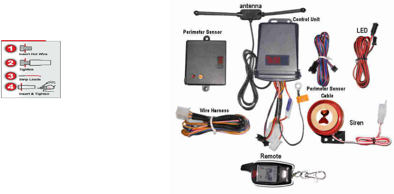
List of Components
Control Unit – 4” x 2 7/8” x 1 1/4”
LCD Transceiver/Pager - 2 7/8” x 1 3/8” x 5/8”
Siren – 2 ” Diameter x 1 7/8” High
LED – High Intensity Blue
Antenna – 5/8” x 1/1/2” x 3/8” with 2 2 1/2” antennas
Perimeter Sensor – 2 5/8” x 2 1/4” x 1/2”
Wiring Harness
Battery – 1.5V “AAA”
(1)
Getting Familiar with the TW-1000
All our systems are tested and programmed before shipping. However, you might
want to familiarize yourself with the alarm before you start the actual installation.
You can check the basic functions of the alarm by connecting 2 wires. Connect the red
wire to Battery Positive (12VDC) and the black wires (the one in the harness) to
the Battery Negative (ground). Plug in the siren, LED, and perimeter sensor (be
careful plugging and unplugging the perimeter sensor .)
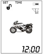
On the remote slide the battery cover down to remove, and insert the AAA battery in
the remote, with the (+) to the left looking at the back of the remote. When the battery
is inserted the remote will play a cascading tune and the icons on the LCD will be
displayed.
Pressing the lock button once will arm the alarm and cause the alarm to shriek once
and the remote to play two notes and display the speaker icon. Pressing the lock button
a second time will put the alarm in to silent mode and speaker icon will now have a
diagonal line through it Pressing the unlock button disengages the alarm.
The brown wire will be connected to a point on the motorcycle that receives +12VDC
when the ignition switch is in the On position (such as the ACC), and receives no
voltage when the ignition switch is in the Off position. The brown wire performs 2
functions:
1) To activate the reminder function. With the alarm in an unarmed condition, touch
the brown wire to the (+) on the battery and then remove it, this simulates the ignition
going from the On position to the Off position and will activate the reminder. The
alarm will give 3 short chirps and then the remote will vibrate play a tune and blink the
display indicating the alarm is not set.
2) When the alarm is armed turning the ignition to the On position will place the alarm
in panic mode, this can be simulated by pressing the lock button to arm the alarm and
then touching the brown wire to (+) 12VDC simulating the key being turned on the
motorcycle, the alarm will panic and remote will vibrate and light display danger icons
and an audible tone. For further information on other features such a the perimeter
sensor see the rest of the manual.
(2)
- The remote will make a twinkling sound and the screen will turn green and go out. Adjust
the sensitivity by pressing the Lock button on the front of the remote and releasing. The
sensitivity is changed each time you press the lock button is the alarm acknowledges by the
number of shrieks that come from the siren ranging from 1 to 5. When the desired level is
archived hold the unlock button until the alarm gives double shriek and the remote screen
turns green and goes out, the sensitivity is now set.
Activating the Perimeter Sensor, setting the Time and Alarm – The time, alarm and
activation and deactivation of the perimeter sensor are all set with this procedure. Press the
lock and unlock button simultaneously for about 1 second, this will put the remote in the
program mode for these 3 functions. The screen will turn green and “set time will be
displayed in the upper left of the LCD screen and the minutes display will start blinking.
Pressing the unlock button changes the setting within the function, for example when the
minutes are blinking pressing the unlock button will increment the minutes. Pressing the
Lock key changes the function. TIME SET – Minutes -> TIME SET –Hour -> ALARM
ON/OFF -> ALARM SET -Minutes -> ALARM SET- hour -> PERIMETER SENSOR
ON/OFF -> SAVE/EXIT. The Perimeter sensor is on when the Perimeter icons [ ] are
blinking, when they are solid the perimeter sensor is off. To exit the setup mode, press the
lock button to toggle through the functions until the top of the screen displays SET on one
side and EXIT on the other side. Press the lock and unlock together the siren will chirp and
the remote will return to stand by mode. See following Diagram.
Power Off Memory- If the battery is removed an replaced the TW-1000 will return to it's
prior status, when power is re-applied.
Auto-rearm – If the alarm is armed and the unlock button is pressed the alarm will disarm,
if the motorcycle is not started in 25 seconds it will assume that it was a false disarm signal
and re-arm the alarm and signal the remote it re-armed.
(11)

Motion Sensor (perimeter sensor) – if the alarm is set so the perimeter sensor is on
and the microwave detector detects any movement for 5 seconds the alarm will shriek
5 times ( unless in the silent mode ), flash the lights on the motorcycle, disable the
ignition and turn the display green on the remote, display the perimeter icon [ ] and
flash the headlight icon. If the microwave detector detects movement for 15 seconds
the lights will flash the alarm will sound to 30 seconds in various tones (unless in silent
mode), disable the ignition and the remote will turn yellow display the perimeter icon
[ ] and blink the headlight icon and display the hammer icon. Note: see section on
setting the Perimeter sensor, time and alarm. See Diagram
Motorcycle Locater – Pressing the bell button the side of the remote causes
the siren to sound and go through it's various tones to aid in locating the motorcycle.
Pressing the bell button again will silence the siren and return to it's original status
LED – The LED blinks twice every 2 seconds when the system is armed. If the alarm
was tripped the LED will blink 4 times every 2 seconds until the alarm is reset
(ignition switch turned on then off) .
Back Light – press any button and the remote will light 2 seconds.
Battery Indicator – The LCD transceiver also has a battery icon that
indicates the state of the battery. Note: when inserting the battery, the
LCD/remote will play a tune and display each of the icons on the display,
as it does a self check.
Antenna Icon – The LCD also has an antenna icon with power bars to indicate the
remote in contact with the motorcycle.
Setting The Shock Sensor Sensitivity – The shock sensor has 5 levels of sensitivity
that can be set from the remote. 1 is the most sensitive and 5 is the least sensitive. The
alarm is set to 3 when you receive it. To change the sensitivity:
- Make sure the alarm is not armed.
- Press and hold the unlock button until the siren shrieks once.
(10)
Instructions
All the basic components required including connectors and wire ties have been shipped
with the TW-1000.
However, before beginning the installation of your alarm there are a couple of items
that you may want to consider purchasing for the installation. If you will be riding in
extreme conditions, you may want to purchase some conductive grease for the pins on
the connectors and a tube of RTV silicone to seal the final connections on the
connectors.
The next thing is to determine what features you want to install on your
motorcycle. For the sake of simplicity there are three different levels of
wiring the alarm.
The first requires no skill and consists of connecting 3 wires, one to the battery
positive(+), one to the battery negative(-) and on to the motorcycle frame.
Of course you will have to plug in the siren, LED and perimeter sensor. With these 3
wires connected the alarm has all the features, with the exception of the ignition
switch protection, reminding, ignition disable and flashing directionals.
Second, to add the reminding and ignition switch protection, one
additional wire (Brown) has to be wired to the ACC terminal on your ignition
switch or to any point that receives +12VDC when the ignition switch is on and
no power when the ignition switch is off.
Third, two wires (yellow) can be wired to the directional signal wires to cause the
directional signals to blink when the alarm is alarming or changing functions.
Finally, two wires (pink & Gray) can be added to disable the ignition.
(Note: wiring to your directionals and the ignition disable require some
knowledge of your motorcycle and some basic wiring ability)
The Installation
Determine where to place the components – Most motorcycles have a limited
amount of space, it is recommended that you place all the components where
you would like to install them before doing any wiring. Our WEB page
http://www.internatrix.com has some examples. This is one of the most
important parts of the installation, so take your time and plan your
installation well. The dimensions of the various parts are on the previous
page. On some bikes it may take some real ingenuity.
(3)

Control Unit – Generally the control unit can be mounted under the seat, in the
toolbox, tail section, or select a location best for your motorcycle that will have
minimal exposure to water and excessive heat. If mounting under the seat, make sure
the seat can be replaced without damaging the control unit.
Antenna – The Antenna can be mounted in any location with minimal exposure to
water and heat, such as under the seat or any location that is best for your motorcycle
that will have minimal exposure to water or excessive heat. Do not secure the antenna
until you have tested the alarm, in case it is necessary to re-position, for greater
range.
Siren - The siren can also be mounted in any location using the double sided tape.
Where ever you feel is best for your bike ,see our WEB page for examples. When
mounting the Siren try and place it in a location that is somewhat hidden from plain
sight, but will not block the sound.
LED – The LED can be mounted in any convenient place but we recommend that
it be attach to the frame using tie wraps and double sided tape. Or drilling a whole in
your license plate and mounting where there will be no permanent hole in the
motorcycle. Note: this is a high intensity LED.
Perimeter Sensor – The perimeter sensor is a microwave detector, it will
detect any movement by transmitting a very low power microwave signal.
The signal will transmit thru the seat, so it is recommended to mount under
the seat, or on any horizontal surface that will have a minimal exposure to
water and excessive heat. Since the signal is balloon shaped it is best that the sensor
is mounted horizontal to allow the signal to surround the sensor. After installing and
testing the alarm it may be necessary to adjust the sensitivity. The sensitivity can be
adjusted by watching the red LED on the motion sensor and adjusting the
potentiometer on the sensor. After adjusting, place a small piece of electrical tape over
the adjustment hole.
Note: The Perimeter sensor range is limited by design, to prevent the alarm from
alarming when an automobile parks next to the motorcycle or a person walks past the
motorcycle.
(4)
If triggered by shock again within 10 seconds after being triggered the first time the
siren will sound for 30 seconds with several different sounds, the ignition will be
disengaged and the remote will be yellow showing the shock and headlight icons and
will vibrate 8 times after alarming. When the alarm has been tripped the LED will
continue to blink at a rapid rate indicating the alarm was tripped. The alarm also will
return to the armed standby level.
Silent mode – If the lock button on the front of the alarm is pressed a second time the
alarm will go into the silent mode. In the silent mode the remote will display a diagonal
line through the speaker to indicate the alarm is in the silent mode.
The remote will display the same as in the normal mode, the lights will flash on the
motorcycle but the siren will be silent.
Panic Mode – If the alarm is armed, and an attempt is made to start the motorcycle the
alarm will panic. The remote will flash green to red and display the headlight icon the
shock icon and the exhaust icon, disengage the ignition and shriek the siren in various
modes for 30 seconds. In the panic mode the silent mode of the alarm is over ridden.
Siren Pause – When the alarm is alarming, pressing the lock button on the remote will
pause the alarm .
Arm reminder – After turning off the ignition, if the system is not armed in 8 seconds
the alarm will give 3 short chirps of the siren flash the lights and vibrate the remote as
a reminder to arm the system.
Disarming the Alarm – Press the unlock button on the side of the remote to
disarm the alarm system.. The LCD Remote will display the following:
If the engine is not started within 25 seconds, the alarm will consider it a false disarm
and re-arm the system. To override the false disarm, press the unlock button, wait 5
seconds and press it a second time.
(9)
Operating Instructions
Encoding the LCD Remote/s –The alarm is shipped with the remote/s already
programed, programing should not be required unless you purchased a replacement
remote.
With the alarm not armed!
Press the button on the back of the control unit and hold until the LED comes on,
press any button on the remote and the LED will flash twice and the siren shriek twice
and the remote will play a tune indicating the code was learned. If programing a
second remote, while the button is still pushed, press any button on the second remote,
the LED will flash 4 times and the alarm will shriek 4 times and the remote will play a
tune indicating the code was learned.
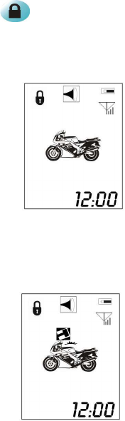
Arming the Alarm – Press the lock button the front of the remote once, the
siren will sound once, and the lights will flash once. In three seconds the system
will arm and the LED will blink twice every two seconds. The remote will display
the lock icon and the speaker icon as shown in the diagram.
When triggered by shock for the first time, the siren will sound 5 times, the lights
will flash 5 times and the ignition will be disengaged. The LCD transceiver will turn
green display the shock and headlight icons as shown in the diagram.
(8)
Wiring the Alarm
The alarm is supplied with several plugs and connectors and a wiring harness
to make the installation simple. However, if you are not comfortable installing
your own alarm you may prefer to have a professional do the installation. You may
also elect to do a minimal installation yourself and have the final 4 wires installed by a
professional. In a minimal installation, you would not connect the two yellow wires to
your turn signals or the gray wire and pink wire used for the ignition
disable function. In a minimal installation, the lights would not blink and the ignition
would not be disabled when in alarm condition, all other functions would work.
1) Plug the LED connector into the matching connector on the Control Unit.
2) Plug the Siren Connector into the matching connector on the Control Unit.
3) Plug the cable with the connector from the control box into the matching
connector on the Perimeter sensor cable and the other end into the Perimeter sensor.
Be careful when unplugging, do not pull off by the wire.
4) Connect the Black wire coming out of the control unit to frame ground, with the
supplied connector. (This is not the black wire in the wiring harness).
The alarm is supplied with a wiring harness that plugs into a connector on the Control
Unit. Wire the harness before plugging into the control unit. We recommend that
you remove the fuse.
1) Black Wire – To the battery Ground (-). Use the supplied crimp lug.
2) Red Wire (with fuse) – To Battery Positive (+). Use the supplied Crimp lug.
3) Brown wire to ACC on the key switch. Use the small crimp lug. This can be
determined by the Motorcycle manual wiring diagram or using a meter to determine
what contact gets +12VDC when the key switch is in ACC position. If you do not
have an ACC on your motorcycle, connect this wire to any circuit that gets +12VDC
when the ignition switch is in the on position, and no voltage when in the off position.
4) Yellow Wires (2) – Using the supplied Posi-Taps, One wire goes to the right
directional and one to the left directional, this can be determined by the Motorcycle
manual wiring diagram, or by tracing the wires from the rear directional. This
connection is optional, and causes the directional lights to flash when in alarm
condition. If you are doing a minimal configuration, do not connect these wires.
Caution!! If these wires are not connected make sure they
are insulated from ground.
(5)
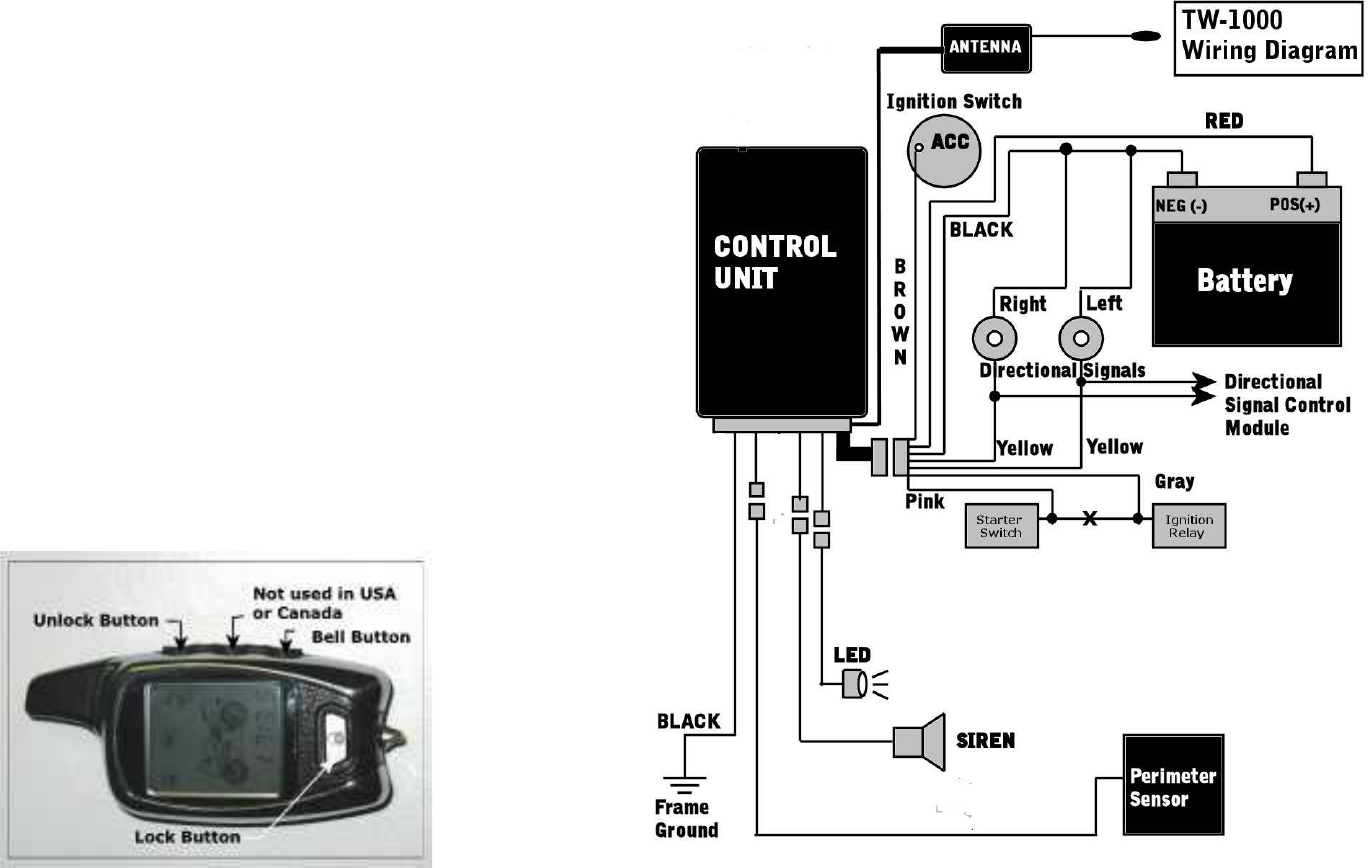
5) Gray Wire and Pink Wire are for the ignition disable feature.
The pink and gray wires are connected to the contacts on a Normally Closed relay in
the control unit. When the alarm is off or in the arm mode the connection acts as
closed switch, between the pink and gray wires. When the system alarms the relay
opens and breaks the circuit and acts as an opened switch, between the pink and gray
wires. Since the connection is normally closed, and only opened in alarm condition,
if the alarm became non functional for some reason the motorcycle would still run as
usual. Refer to the wiring diagram on page 7.The best way to wire in the ignition
disable can vary from motorcycle to motorcycle and personal preferences. We
recommend connecting the ignition disable between the starter switch and starter
relay, this prevents the bike from being started when the alarm is an alarming
condition.
Caution: When connecting the ignition disable, use the
suggested method between the Starter switch and starter
relay, other methods could cause the bike to loose power if
the lock button is accidentally pressed.
Installing the Battery in the LCD Remote – Slide the battery cover down and
insert the supplied AAA battery into the LCD remote, with positive (+) terminal to the
left side when looking at the back (non spring side). The LCD transceiver will play a
tune, while displaying the various icons on the LCD.
(6) (7)