Internatrix TW-1000 Two way motorcycle alarm system User Manual
Internatrix, LLC Two way motorcycle alarm system
UserManual.wiki
>
Internatrix
>
TW 1000 User Manual
User manual
Navigation menu
Upload a User Manual
Namespaces
Wiki Guide
HTML
PDF
Info
Views
User Manual
Discussion / Help
Navigation

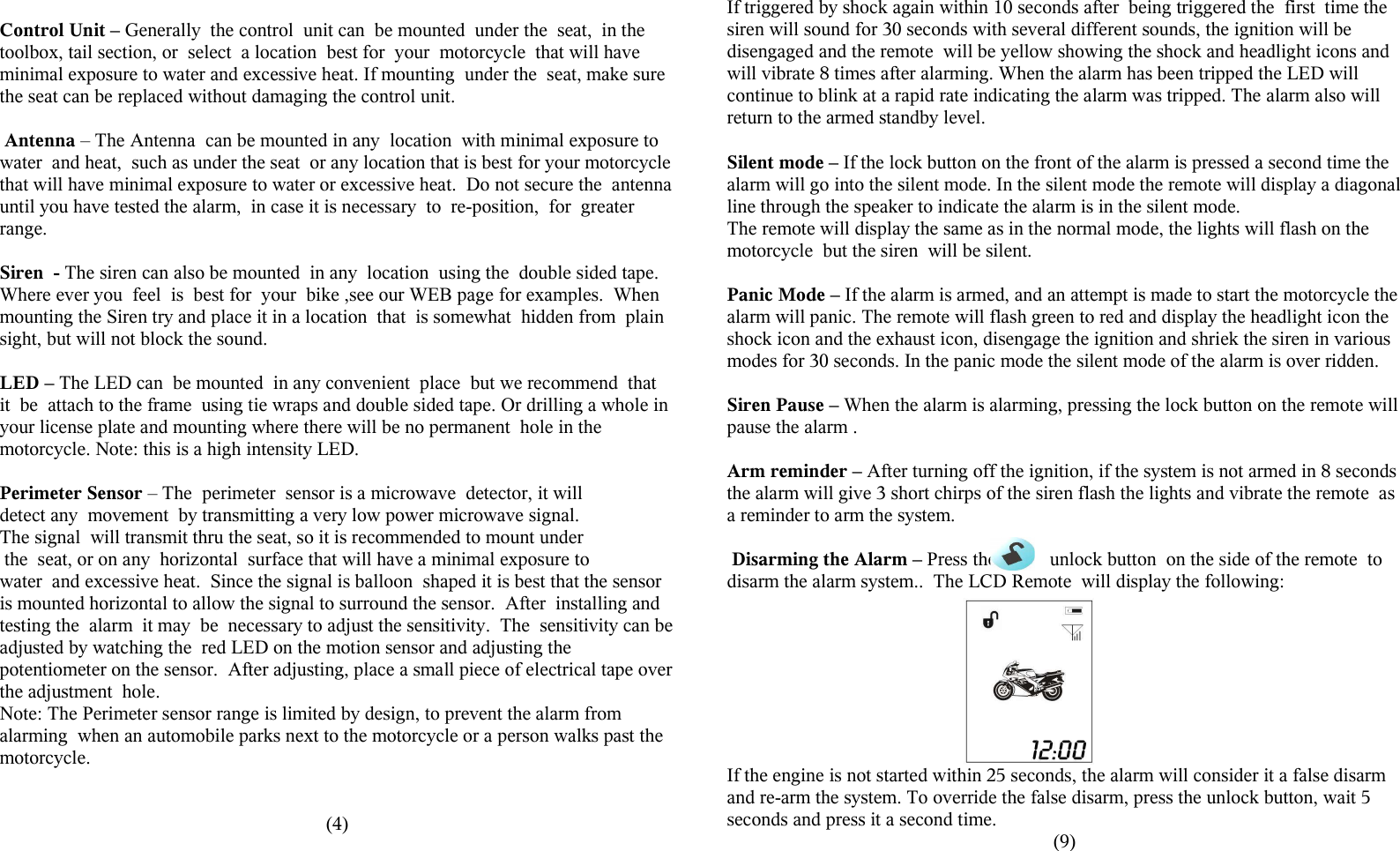
![Getting Familiar with the TW-1000All our systems are tested and programmed before shipping. However, you might want to familiarize yourself with the alarm before you start the actual installation. You can check the basic functions of the alarm by connecting 2 wires. Connect the red wire to Battery Positive (12VDC) and the black wires (the one in the harness) to the Battery Negative (ground). Plug in the siren, LED, and perimeter sensor (be careful plugging and unplugging the perimeter sensor .) On the remote slide the battery cover down to remove, and insert the AAA battery in the remote, with the (+) to the left looking at the back of the remote. When the battery is inserted the remote will play a cascading tune and the icons on the LCD will be displayed.Pressing the lock button once will arm the alarm and cause the alarm to shriek once and the remote to play two notes and display the speaker icon. Pressing the lock button a second time will put the alarm in to silent mode and speaker icon will now have a diagonal line through it Pressing the unlock button disengages the alarm. The brown wire will be connected to a point on the motorcycle that receives +12VDC when the ignition switch is in the On position (such as the ACC), and receives no voltage when the ignition switch is in the Off position. The brown wire performs 2 functions:1) To activate the reminder function. With the alarm in an unarmed condition, touch the brown wire to the (+) on the battery and then remove it, this simulates the ignition going from the On position to the Off position and will activate the reminder. The alarm will give 3 short chirps and then the remote will vibrate play a tune and blink the display indicating the alarm is not set.2) When the alarm is armed turning the ignition to the On position will place the alarm in panic mode, this can be simulated by pressing the lock button to arm the alarm and then touching the brown wire to (+) 12VDC simulating the key being turned on the motorcycle, the alarm will panic and remote will vibrate and light display danger icons and an audible tone. For further information on other features such a the perimeter sensor see the rest of the manual.(2)- The remote will make a twinkling sound and the screen will turn green and go out. Adjust the sensitivity by pressing the Lock button on the front of the remote and releasing. The sensitivity is changed each time you press the lock button is the alarm acknowledges by the number of shrieks that come from the siren ranging from 1 to 5. When the desired level is archived hold the unlock button until the alarm gives double shriek and the remote screen turns green and goes out, the sensitivity is now set.Activating the Perimeter Sensor, setting the Time and Alarm – The time, alarm and activation and deactivation of the perimeter sensor are all set with this procedure. Press the lock and unlock button simultaneously for about 1 second, this will put the remote in the program mode for these 3 functions. The screen will turn green and “set time will be displayed in the upper left of the LCD screen and the minutes display will start blinking. Pressing the unlock button changes the setting within the function, for example when the minutes are blinking pressing the unlock button will increment the minutes. Pressing the Lock key changes the function. TIME SET – Minutes -> TIME SET –Hour -> ALARM ON/OFF -> ALARM SET -Minutes -> ALARM SET- hour -> PERIMETER SENSOR ON/OFF -> SAVE/EXIT. The Perimeter sensor is on when the Perimeter icons [ ] are blinking, when they are solid the perimeter sensor is off. To exit the setup mode, press the lock button to toggle through the functions until the top of the screen displays SET on one side and EXIT on the other side. Press the lock and unlock together the siren will chirp and the remote will return to stand by mode. See following Diagram.Power Off Memory- If the battery is removed an replaced the TW-1000 will return to it's prior status, when power is re-applied.Auto-rearm – If the alarm is armed and the unlock button is pressed the alarm will disarm, if the motorcycle is not started in 25 seconds it will assume that it was a false disarm signal and re-arm the alarm and signal the remote it re-armed.(11)](https://usermanual.wiki/Internatrix/TW-1000/User-Guide-1066264-Page-4.png)
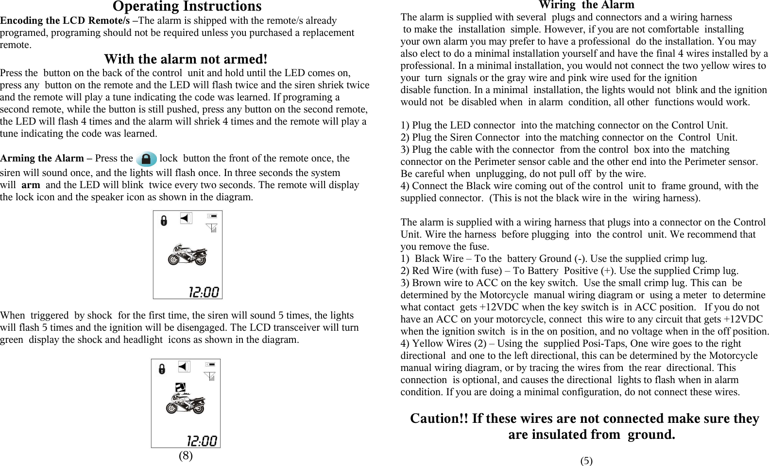
![Motion Sensor (perimeter sensor) – if the alarm is set so the perimeter sensor is on and the microwave detector detects any movement for 5 seconds the alarm will shriek 5 times ( unless in the silent mode ), flash the lights on the motorcycle, disable the ignition and turn the display green on the remote, display the perimeter icon [ ] and flash the headlight icon. If the microwave detector detects movement for 15 seconds the lights will flash the alarm will sound to 30 seconds in various tones (unless in silent mode), disable the ignition and the remote will turn yellow display the perimeter icon [ ] and blink the headlight icon and display the hammer icon. Note: see section on setting the Perimeter sensor, time and alarm. See DiagramMotorcycle Locater – Pressing the bell button the side of the remote causes the siren to sound and go through it's various tones to aid in locating the motorcycle. Pressing the bell button again will silence the siren and return to it's original statusLED – The LED blinks twice every 2 seconds when the system is armed. If the alarm was tripped the LED will blink 4 times every 2 seconds until the alarm is reset (ignition switch turned on then off) . Back Light – press any button and the remote will light 2 seconds.Battery Indicator – The LCD transceiver also has a battery icon that indicates the state of the battery. Note: when inserting the battery, the LCD/remote will play a tune and display each of the icons on the display, as it does a self check.Antenna Icon – The LCD also has an antenna icon with power bars to indicate the remote in contact with the motorcycle.Setting The Shock Sensor Sensitivity – The shock sensor has 5 levels of sensitivity that can be set from the remote. 1 is the most sensitive and 5 is the least sensitive. The alarm is set to 3 when you receive it. To change the sensitivity:- Make sure the alarm is not armed.- Press and hold the unlock button until the siren shrieks once.(10)InstructionsAll the basic components required including connectors and wire ties have been shipped with the TW-1000. However, before beginning the installation of your alarm there are a couple of items that you may want to consider purchasing for the installation. If you will be riding in extreme conditions, you may want to purchase some conductive grease for the pins on the connectors and a tube of RTV silicone to seal the final connections on the connectors. The next thing is to determine what features you want to install on your motorcycle. For the sake of simplicity there are three different levels ofwiring the alarm. The first requires no skill and consists of connecting 3 wires, one to the battery positive(+), one to the battery negative(-) and on to the motorcycle frame. Of course you will have to plug in the siren, LED and perimeter sensor. With these 3 wires connected the alarm has all the features, with the exception of the ignition switch protection, reminding, ignition disable and flashing directionals. Second, to add the reminding and ignition switch protection, one additional wire (Brown) has to be wired to the ACC terminal on your ignition switch or to any point that receives +12VDC when the ignition switch is on andno power when the ignition switch is off. Third, two wires (yellow) can be wired to the directional signal wires to cause the directional signals to blink when the alarm is alarming or changing functions. Finally, two wires (pink & Gray) can be added to disable the ignition. (Note: wiring to your directionals and the ignition disable require some knowledge of your motorcycle and some basic wiring ability) The InstallationDetermine where to place the components – Most motorcycles have a limited amount of space, it is recommended that you place all the components where you would like to install them before doing any wiring. Our WEB page http://www.internatrix.com has some examples. This is one of the most important parts of the installation, so take your time and plan your installation well. The dimensions of the various parts are on the previous page. On some bikes it may take some real ingenuity.(3)](https://usermanual.wiki/Internatrix/TW-1000/User-Guide-1066264-Page-5.png)