Invacare Personal Lift 1200 Users Manual 1150696A
Invacare Personal Lift 1300 1150696A__011409
1600 to the manual afd9e188-271a-4480-aaaa-3b87f91a95fa
2015-02-02
: Invacare Invacare-Invacare-Personal-Lift-1200-Users-Manual-433557 invacare-invacare-personal-lift-1200-users-manual-433557 invacare pdf
Open the PDF directly: View PDF ![]() .
.
Page Count: 36
Owner’s Operator and Maintenance Manual
DEALER: This manual MUST be given to
the user of the patient lift.
USER: BEFORE using this patient lift, read
this manual and save for future reference.
For more information regarding
Invacare Continuing Care, Inc. (ICCI) products,
parts, and services, please visit www.invacare-ccg.com
or call 800-668-2337
Invacare Continuing Care, Inc.
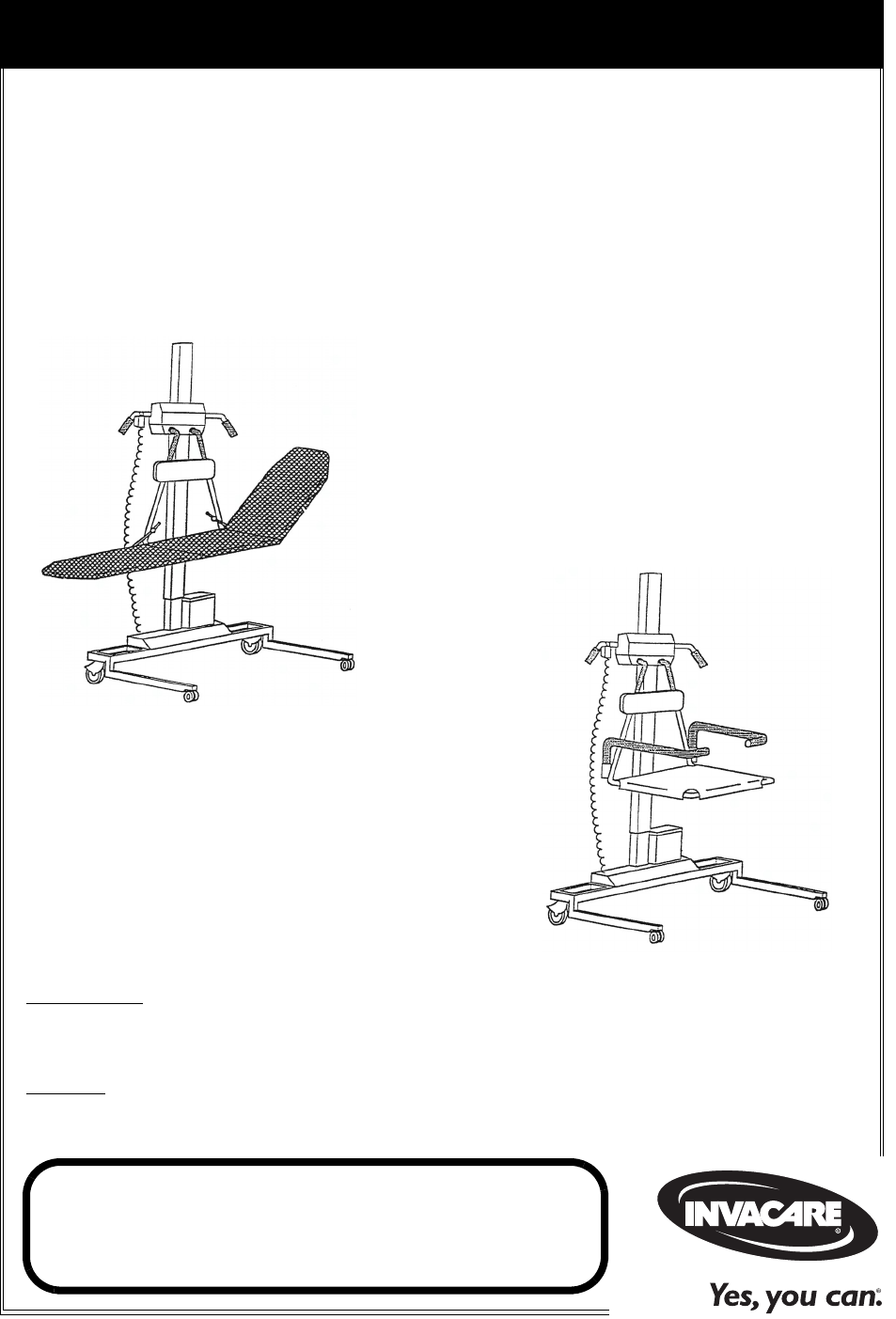
Traverse Lift/Transporter
1200 Series
and
1500 Series
1300 Series
and
1600 Series

Traverse Lift/Transporter 2Part No. 1150696
WARNING
DO NOT USE THIS PRODUCT OR ANY AVAILABLE OPTIONAL
EQUIPMENT WITHOUT FIRST COMPLETELY READING AND
UNDERSTANDING THESE INSTRUCTIONS AND ANY
ADDITIONAL INSTRUCTIONAL MATERIAL SUCH AS OWNER’S
MANUALS, SERVICE MANUALS OR INSTRUCTION SHEETS
SUPPLIED WITH THIS PRODUCT OR OPTIONAL EQUIPMENT. IF
YOU ARE UNABLE TO UNDERSTAND THE WARNINGS,
CAUTIONS OR INSTRUCTIONS, CONTACT A HEALTHCARE
PROFESSIONAL, DEALER OR TECHNICAL PERSONNEL BEFORE
ATTEMPTING TO USE THIS EQUIPMENT - OTHERWISE, INJURY
OR DAMAGE MAY OCCUR.
ACCESSORIES WARNING
ICCI products are specifically designed and manufactured for use in conjunction
with ICCI accessories. Accessories designed by other manufacturers have not been
tested by ICCI and are not recommended for use with ICCI products.
Forfurtherinformationonthisproduct,pleasecallthefollowing:
CustomerService‐1‐800‐668‐2337
TechnicalSupport‐1‐800‐668‐2337

TABLE OF CONTENTS
Part No. 1150696 3Traverse Lift/Transporter
TABLE OF CONTENTS
SPECIAL NOTES ................................................................................ 5
LABEL LOCATION ............................................................................ 6
TYPICAL PRODUCT PARAMETERS .................................................... 7
Traverse Lifts...............................................................................................................................................7
Scale...............................................................................................................................................................7
SECTION 1—GENERAL GUIDELINES ................................................... 8
Operating the Lift .......................................................................................................................................8
Lifting/Transferring .....................................................................................................................................8
Performing Maintenance ...........................................................................................................................9
Electrical - Grounding Instructions ........................................................................................................9
Pinch Points..................................................................................................................................................9
SECTION 2—OPERATING THE BATH LIFT ........................................ 10
Locking and Unlocking the Casters......................................................................................................10
Transferring into/out of the Lift............................................................................................................11
Using the Stretcher..............................................................................................................................11
Using the Seat .......................................................................................................................................11
Transferring into/out of the Tub...........................................................................................................12
Raising/Lowering the Bath Lift...............................................................................................................13
Disinfecting the Lift ..................................................................................................................................14
Mounting the Battery Charger ..............................................................................................................15
Charging the Battery................................................................................................................................16
Using the Wall-Mounted Battery Charger.....................................................................................16
Using the On-Board Battery Charger.............................................................................................18
SECTION 3—USING THE SCALE ....................................................... 19
Removing/Installing the Bath Scale .......................................................................................................19
Functions ....................................................................................................................................................21
Replacing the Battery...............................................................................................................................22
Calibrating the 1100 Bath Scale.............................................................................................................23
SECTION 4—ADJUSTMENTS ............................................................ 24
Adjusting the Frame Column Height ...................................................................................................24
Adjusting the Lift Column.......................................................................................................................25

TABLE OF CONTENTS
Traverse Lift/Transporter 4Part No. 1150696
TABLE OF CONTENTS
SECTION 5— MAINTENANCE AND TROUBLESHOOTING .................. 26
Safety Inspection Checklists...................................................................................................................26
Inspect/Adjust Initially and Monthly.................................................................................................26
Adjust Every 6 Months .......................................................................................................................26
Care and Maintenance of Bath Lift.......................................................................................................27
Detecting Wear and Damage ................................................................................................................27
Cleaning the Lift........................................................................................................................................27
Troubleshooting........................................................................................................................................28
Lifts..........................................................................................................................................................28
Scale ........................................................................................................................................................28
SECTION 6—ACCESSORIES .............................................................. 29
Installing the Stretcher Cover ...............................................................................................................29
Installing the Short Stretcher Padded Cover .....................................................................................30
LIMITED WARRANTY ..................................................................... 35

SPECIAL NOTES
Part No. 1150696 5Traverse Lift/Transporter
SPECIAL NOTES
Signalwordsareusedinthismanualandapplytohazardsorunsafepracticeswhich
couldresultinpersonalinjuryorpropertydamage.Refertothetablebelowfor
definitionsofthesignalwords.
NOTICE
THE INFORMATION CONTAINED IN THIS DOCUMENT IS SUBJECT TO
CHANGE WITHOUT NOTICE.
WARNING
MAINTENANCE
Maintenance MUST be performed ONLY by qualified personnel.
SIGNAL WORD MEANING
DANGER Danger indicates an imminently hazardous situation which, if not avoided, will
result in death or serious injury.
WARNING Warning indicates a potentially hazardous situation which, if not avoided, could
result in death or serious injury.
CAUTION Caution indicates a potentially hazardous situation which, if not avoided, may
result in property damage or minor injury or both.

TYPICAL PRODUCT PARAMETERS
Part No. 1150696 7Traverse Lift/Transporter
TYPICAL PRODUCT PARAMETERS
Traverse Lifts
Scale
1200 SERIES 1300 SERIES 1500 SERIES 1600 SERIES
FRAME: Powder coated tubular steel
SUPPORT ARMS AND
RELATED ACCESSORIES:
Stainless steel
LIFT DRIVE MECHANISM: Battery powered ball screw actuator
CASTERS
FRONT:
REAR:
Locking and steering hospital grade casters
3 in
5 in
ELECTRICAL
MOTOR:
BATTERY:
BATTERY CHARGER:
INPUT:
12V DC
12V DC, 15 amp/hr, sealed gel-cell
Wall-mounted automatic rapid charging with a rate of 2 amps per hr
115AC, 60Hz, 1.2 amp
STRETCHER
STANDARD:
N MODELS:
80.5 in x 18 in
70 in x 16 in
n/a
n/a
80.5 in x 18 in
70 in x 16 in
n/a
n/a
SEAT
WIDTH:
DEPTH:
n/a
n/a
16.5 in
16.5 in
n/a
n/a
16.5 in
16.5 in
BASE
HEIGHT (CLEARANCE):
WIDTH (OUTER/INNER):
DEPTH (MIN/MAX):
5 in
34.5 in/28.5 in
29.5 in/33 in
5 in
34.5 in/28.5 in
29.5 in/33 in
5 in
34.5 in/28.5 in
32.5 in/36 in
5 in
34.5 in/28.5 in
32.5 in/36 in
PERFORMANCE
VERTICAL TRAVEL:
COLUMN POSITIONS:
30 in
7
SHIPPING WEIGHT: 236 lbs (107 Kg)
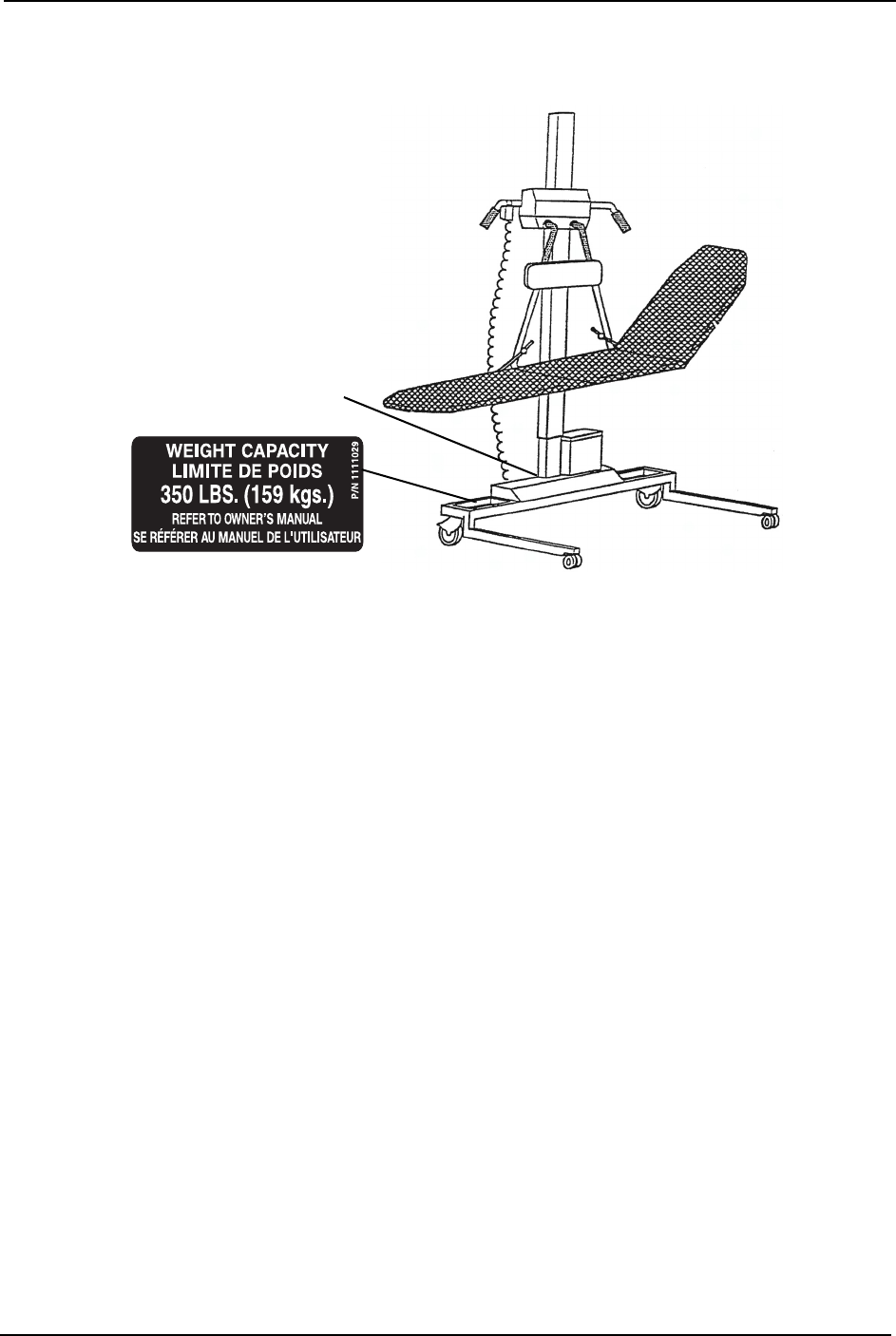
WEIGHT LIMITATION: 350 lbs (159 Kg)
COLORS: White White Grey Grey
WEIGHT RANGE: Up to 350 lbs (158.7 Kg)
RESOLUTION: +/- 1 lbs (0.4 Kg)
DISPLAY: Liquid Crystal Digital
AUTOMATIC POWER DOWN: One minute after processor displays weight data
SIZE: 6” H x 8” W x 7” D
WEIGHT: 25 lbs
POWER: 9-Volt Alkaline battery (included)
BATTERY LIFE: Approximately 3000 readings

GENERAL GUIDELINES
Traverse Lift/Transporter 8Part No. 1150696
SECTION 1—GENERAL GUIDELINES
WARNING
SECTION 1 - GENERAL GUIDELINES contains important information for the safe
operation and use of this product.
Operating the Lift
Checkallpartsforshippingdamagebeforeusing.Incaseofdamage,DONOTusethe
equipment.Contactthedealerorcustomerserviceforfurtherinstructions.
DONOTattemptanytransferwithoutapprovaloftheresident’sphysician,nurseor
medicalassistant.Thoroughlyreadtheinstructionsinthisowner’smanual,observea
trainedteamofexpertsperformtheliftingproceduresandthenperformtheentirelift
procedureseveraltimeswithpropersupervisionandacapableindividualactingasa
resident.
Usecommonsenseinalllifts.Specialcaremustbetakenwithpeoplewithdisabilities
whocannotfullycooperatewhilebeingtransferred.
AlthoughICCIrecommendsthattwoassistantsbeusedforallliftingandtransferring
procedures,ourequipmentwillpermitproperoperationbyoneassistant.Theuseofone
assistantisbasedontheevaluationofthehealthcareprofessionalforeachindividualcase.
DONOTexceedmaximumweightlimitationofthelift.Theweightlimitationforthelift
is350lbs.
ALWAYSkeephandsandfingersclearofmovingpartstoavoidinjury.
Lifting/Transferring
ICCIrecommendstheuseofthesafetystrapandshoulderharnesswhenusingthebath
lift.Alwaysadjustthesafetystrapandshoulderharnessforsafetyandcomfortbefore
transport.
Duringtransfer,raisetheseatsotheresident’sfeetaresuspendedfromthefloor.DONOT
rollcasterbaseoverobjectssuchascarpet,raisedcarpetbindings,doorframes,orany
unevensurfacesorobstaclesthatwouldcreateanimbalanceoftheliftandcouldcause
thelifttotipover.
Locktherearcastersofthebathliftwhentransferringanindividualontotheseator
stretcher.Lockingtherearcasterswillstabilizetheliftandhelppreventitfromshifting
duringtransfer.

GENERAL GUIDELINES
Part No. 1150696 9Traverse Lift/Transporter
Performing Maintenance
RefertoMAINTENANCEANDTROUBLESHOOTINGonpage 26foramaintenance
scheduleandprocedures.
Regularmaintenanceofliftsandaccessoriesisnecessarytoassureproperoperation.
Castersandaxleboltsrequireinspectionseverysixmonthstocheckfortightness,wear,
debris(suchashairanddirt)andthattheyrollfree.
Afterthefirsttwelvemonthsofoperation,inspectallglides,rollers,andfastenersfor
wear.Makethisinspectioneverysixmonthsthereafter.Ifthemetalisworn,theparts
MUSTbereplaced.
BearingscrewsontheliftcolumnMUSTbeadjustedregularly.Otherwise,theliftcolumn
mayseizeandbecomeinoperable.RefertoTroubleshootingonpage 28.
DONOTattempttoopenthemotororobtainlocalserviceasthiswillVOIDthewarranty
andmayresultindamageandacostlyrepair.ConsultyourdealerorICCIforfurther
information.
Electrical - Grounding Instructions
DONOT,underanycircumstances,cutorremovetheroundgroundingprongfromany
plug.Somedevicesareequippedwiththree‐prong(grounding)plugsforprotection
againstpossibleshockhazards.Whereatwo‐prongwallreceptacleisencountered,itis
thepersonalresponsibilityandobligationofthecustomertocontactaqualified
electricianandhavethetwo‐prongreceptaclereplacedwithaproperlygroundedthree‐
prongwallreceptacleinaccordancewiththeNationalElectricalCode.Ifyoumustusean
extensioncord,useonlyathree‐wireextensioncordhavingthesameorhigherelectrical
ratingasthedevicebeingconnected.Inaddition,ICCIhasplacedRED/ORANGE
WARNINGTAGSonsomeequipment.DONOTremovethesetags.Carefullyread
battery/batterychargerinformationpriortoinstalling,servicingoroperatingyourlift.
Pinch Points
WARNING
Pinch points exist at base of lift. Be careful, injury could occur.

OPERATING THE BATH LIFT
Traverse Lift/Transporter 10 Part No. 1150696
SECTION 2—OPERATING THE
BATH LIFT
WARNING
DO NOT attempt any transfer of a resident without approval of the resident's
physician, nurse, or medical assistant. Thoroughly read the instructions in this
owner's manual, observe a trained team of experts performing the lifting
procedures and then perform the entire lift procedure several times with proper
supervision and a capable individual acting as a resident.
ICCI recommends the use of the safety strap and shoulder harness when using the
bath lift. Always adjust the safety strap and shoulder harness for safety and comfort
before transferring the resident onto the chair.
The safety strap should be used when lifting or transferring. Otherwise, the resident
may fall from the seat.
Adjustments for safety and comfort should be made before moving the resident.
Lock the rear casters of the bath lift when transferring an individual onto the seat or
stretcher. Locking the rear casters will stabilize the lift and help prevent it from
shifting during transfer.
Each facility and each resident will require a unique set of instructions and
procedures to follow for each bath. Check with your supervisor and the resident’s
chart for the proper procedures to follow.
Review and practice the operation with an able bodied assistant before attempting
with a resident.
NOTE:ICCIrecommendsthattwoassistantsbeusedforallliftingpreparationandtransferringto/
fromprocedures;however,thebathliftcanbeoperatedwithoneassistant.
Locking and Unlocking the Casters
NOTE:Forthisprocedure,referto
FIGURE 2.1.
1. Lockthetworearlockingcastersonthe
liftbypressingdownonthelocking
pedalwithyourfoot.
2. Unlockthelockingcastersontheliftby
liftinguponthelockingpedalwith
yourfoot.
FIGURE 2.1 Locking and Unlocking the
Casters
Lock
Unlock
Locking Pedal
Locking
Pedal
OPERATING THE BATH LIFT
Part No. 1150696 11 Traverse Lift/Transporter
Transferring into/out of the Lift
Using the Stretcher
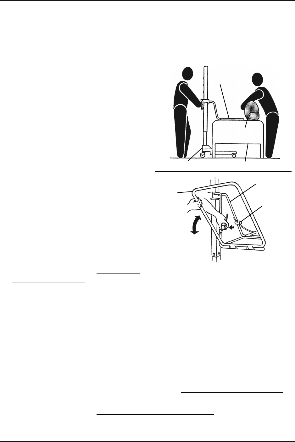
NOTE:Forthisprocedure,refertoFIGURE 2.2.
NOTE:Totransferoutofthelift,reversethis
procedure.
1. Positiontheliftnexttothebedwiththe
stretcherparalleltothebed.
2. Ifnecessary,unfoldthestretcherby
performingthefollowingsteps
(Detail“A”):
A. Pressandholdthebuttononthe
stretcherframe.
B. Lowerthewingarmdowntothe
desiredposition.
C. RepeatstepsAandBforthe
oppositewingarm.
3. Lowerthestretchertothebedheight.
RefertoRaising/LoweringtheBathLift
onpage 13.
4. Rolltheresidenttothesideawayfrom
thestretcher.
5. Pushthelifttowardtheresident.
6. Lockthecasters.RefertoLockingand
UnlockingtheCastersonpage 10.
FIGURE 2.2 Transferring into/out of the
Lift - Using the Stretcher
7. Rolltheresidentontothestretcher.
8. Installthesideguardandstraps(notshown).
NOTE:Theresidentpositioncanbeadjustedbyraisingorloweringthestretcherends.
Using the Seat
NOTE:Forthisprocedure,refertoFIGURE 2.3onpage 12.
NOTE:Totransferoutofthelift,reversethisprocedure.
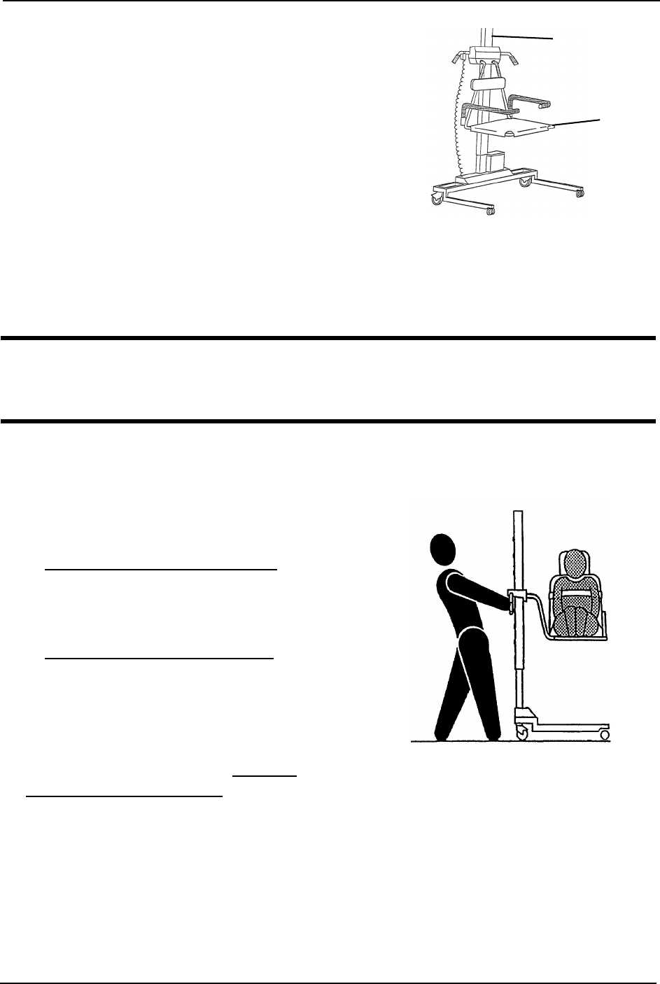
1. Positiontheliftnexttotheseatedresident.
2. Lowertheseattotheresident’sseatheight.RefertoRaising/LoweringtheBathLifton
page 13.
3. Lockthecasters.RefertoLockingandUnlockingtheCastersonpage 10.
4. Swingoneorbotharmrestsoutoftheway.
Bed
Resident
Stretcher
Lift
Button
Wing
Arm
Stretcher
Frame
DETAIL “A”
NOTE:Stretcher
covernotshown
forclarity.
OPERATING THE BATH LIFT
Traverse Lift/Transporter 12 Part No. 1150696
5. Transfertheresidentontotheseat.
NOTE:Usethetransfermethodsprescribedby
thefacilityandtheneedsoftheresident.
6. Securetheresidentintheseatusingthe
straps(notshown).
7. Swingthearmrestsbackintoposition.
FIGURE 2.3 Transferring into/out of the
Lift - Using the Seat
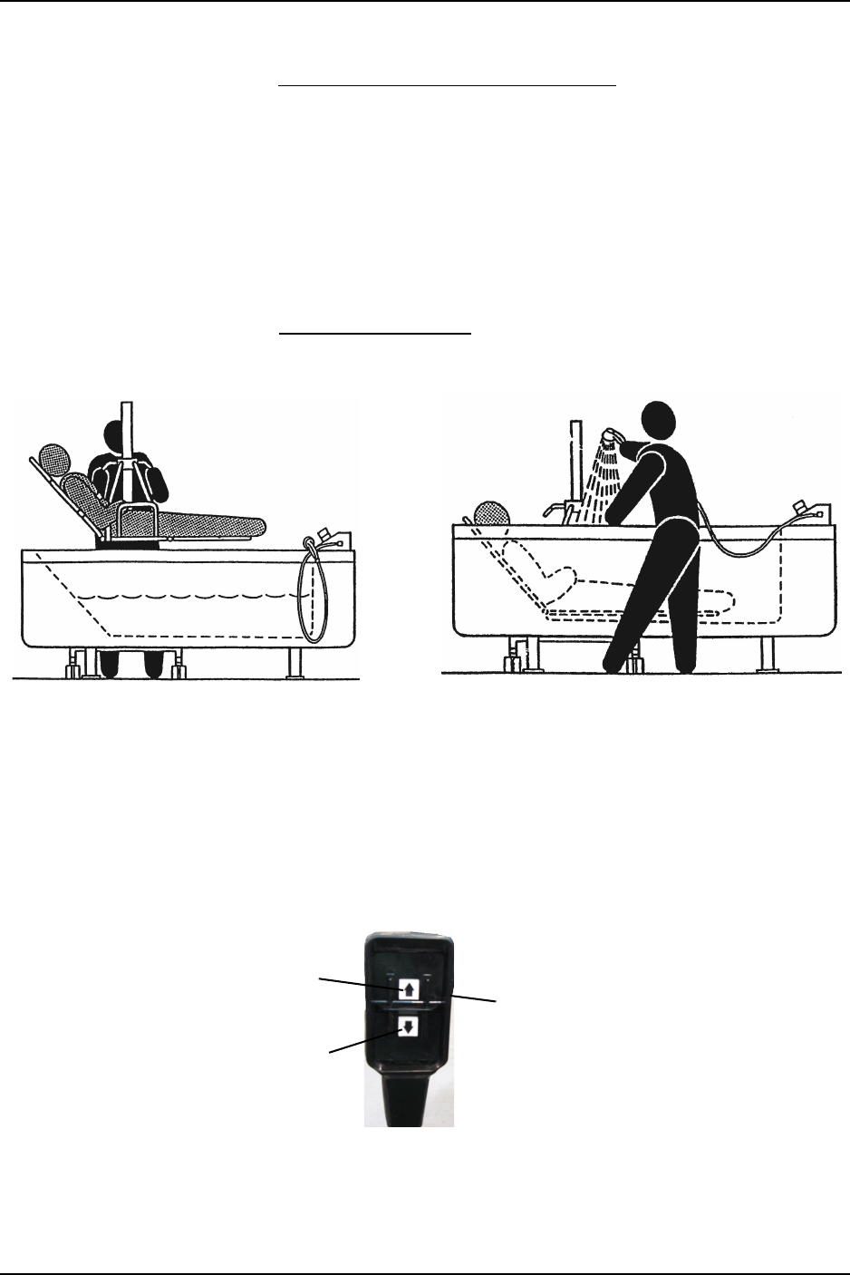
Transferring into/out of the Tub
CAUTION
The bath lift is designed for use with Sit and Supine Tubs only. The seat does not fit
into Side Entry tubs.
NOTE:Forthisprocedure,refertoFIGURE 2.4andFIGURE 2.5onpage 13.
NOTE:Totransferoutofthetub,reversethisprocedure.
1. Preparethetubforbathing.Refertothe
tubowner’smanual.
2. Transfertheresidentintothelift.Refer
toTransferringinto/outoftheLifton
page 11.
3. Positiontheliftseatsothatthe
resident’sfeetareoffofthefloor.Refer
toRaising/LoweringtheBathLifton
page 13.
NOTE:Positiontheliftseatatacomfortable
lowheightsothatthecaregivercanmaintain
eyecontactwiththeresident.
4. Unlockthecasters.RefertoLocking
andUnlockingtheCastersonpage 10.
5. Movetheresidenttothebathingunit
usingthelift.
FIGURE 2.4 Transferring into/out of the
Tub
6. HeightAdjustableBathingUnits‐Adjusttheheightofthetubtothelowestposition.
7. Adjusttheheightoftheseatorstretchersoitisslightlyhigherthanthesideofthetub.
8. Slowlybegintobringtheresidentoverthetub.
NOTE:Ifusingtheseat,theresident’slegsmayneedtobeplacedoverthesideofthetub.
Seat
Lift
NOTE:Stretchershown.
OPERATING THE BATH LIFT
Part No. 1150696 13 Traverse Lift/Transporter
9. Centertheresidentoverthetub.
10. Lockthecasters.RefertoLockingandUnlockingtheCastersonpage 10.
11. Performoneorbothofthefollowing:
•Lowertheresidentintothetub,makingsureallpartsofthestretcherorseatclear
thetubedges.
•Raisetheheightoftheheightadjustabletub.
12. Bathetheresident.
13. ReverseSTEPS2thru11totransfertheresidentoutofthetub.
14. Disinfectthelift.RefertoDisinfectingtheLiftonpage 14
FIGURE 2.5 Transferring into/out of the Tub
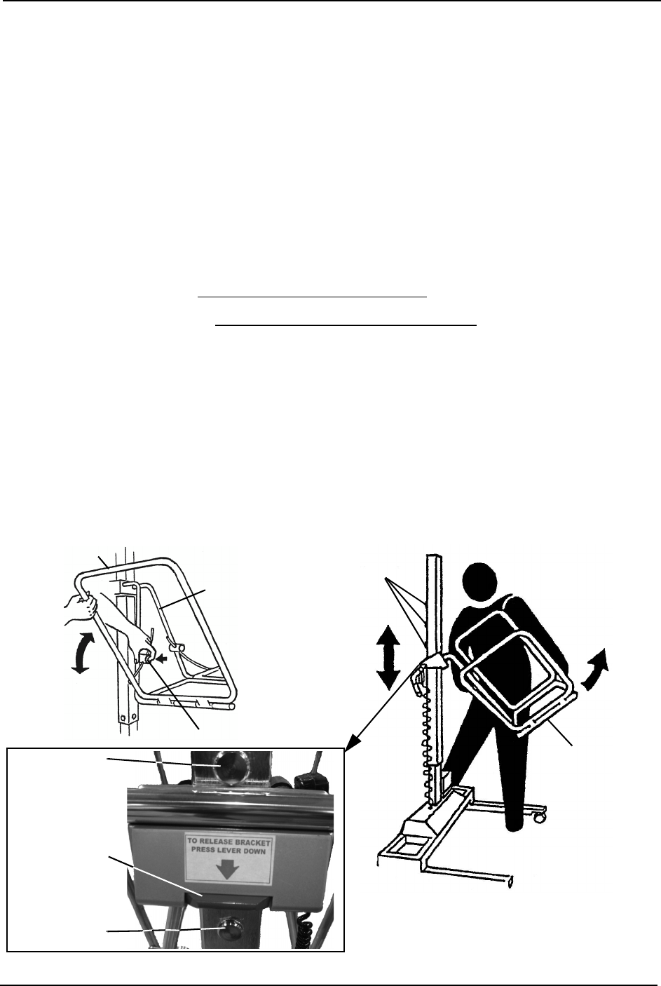
Raising/Lowering the Bath Lift
NOTE:Forthisprocedure,refertoFIGURE 2.6.
•Toraisethebathlift,presstheuparrowbuttononthehandpendant.
•Tolowerthebathlift,pressthedownarrowbuttononthehandpendant.
FIGURE 2.6 Raising/Lowering the Bath Lift
Centering the Resident Over the Tub Bathing the Resident
Up
Arrow
Down
Arrow
Hand
Pendant

OPERATING THE BATH LIFT
Traverse Lift/Transporter 14 Part No. 1150696
Disinfecting the Lift
NOTE:Forthisprocedure,refertoFIGURE 2.7onpage 15.
WARNING
The stretcher or seat and arms of the lift must be disinfected after each use with a
bath.
ALWAYS wear protective gloves and eye protection when working concentrated
chemical disinfectants.
1. PrepareaworkingsolutionofICCIdisinfectantbydoingthefollowing:
A. Mixconcentrateddisinfectantwithwatertoadilutionrationofhalf‐an‐ounceof
disinfectantperonegallonofwater.Preparethedisinfectantinaccordancewith
theinstructionsonthedisinfectantpackaging.
B. Transferthediluteddisinfectantintoalabeledspraybottle.
NOTE:ThedilutionlabelandbottlesizeMUSTbeaccurateandmatch.
NOTE:Theclosedloopdisinfectantsysteminthetubcanalsobeusedtoobtaindisinfectantfrom
theburpfittingand/ordisinfectantwand.Refertothetubowner’smanualformoreinformation.
NOTE:Thestretchercovermayalsobelaunderedusingthewashingmachine.Refertothe
launderinginstructionstagformachinewashinginstructions.DONOTdryusingaclothesdryer.
2. Positionthebathliftintothetub.RefertoSTEPS6to11inTransferringinto/outofthe
Tubonpage 12.
3. Spraybothsidesoftheseatorstretchersurface,thesafetystrap,theshoulderstrap,
andthearmrestsofthelift.RefertoDetail“A ” ofFIGURE 2.7.
CAUTION
DO NOT spray the push handles, scale, or hand pendant with water or disinfectant.
Directly spraying water or disinfectant on these components may damage the elec-
tronic components.
4. Gentlywipethepushhandles,scale,handpendant,andanyothersurfacesthatwere
handledduringthetransportandbathingoftheresidentwithawashclothcontaining
thediluteddisinfectant.RefertoDetail“B”ofFIGURE 2.7.
5. Letthedisinfectantsitfortenminutes.
6. Aftertenminutes,rinsetheseatsurface,safetystrap,shoulderstrap,armrests,and
anyothernon‐electronicsurfacewiththeshowerwandofthebath.Refertothe
individualbathingunit’sowner’smanualforusingtheshowerwand.
7. Lightlywipethepushhandles,scale,andhandpendantwithadampcloth.
8. Dryallsurfaceswithacleantowel.
9. Removethebathliftfromthetub.ReverseSTEPS13to16inLockingandUnlocking
theCastersonpage 10.
OPERATING THE BATH LIFT
Part No. 1150696 15 Traverse Lift/Transporter
FIGURE 2.7 Disinfecting the Lift
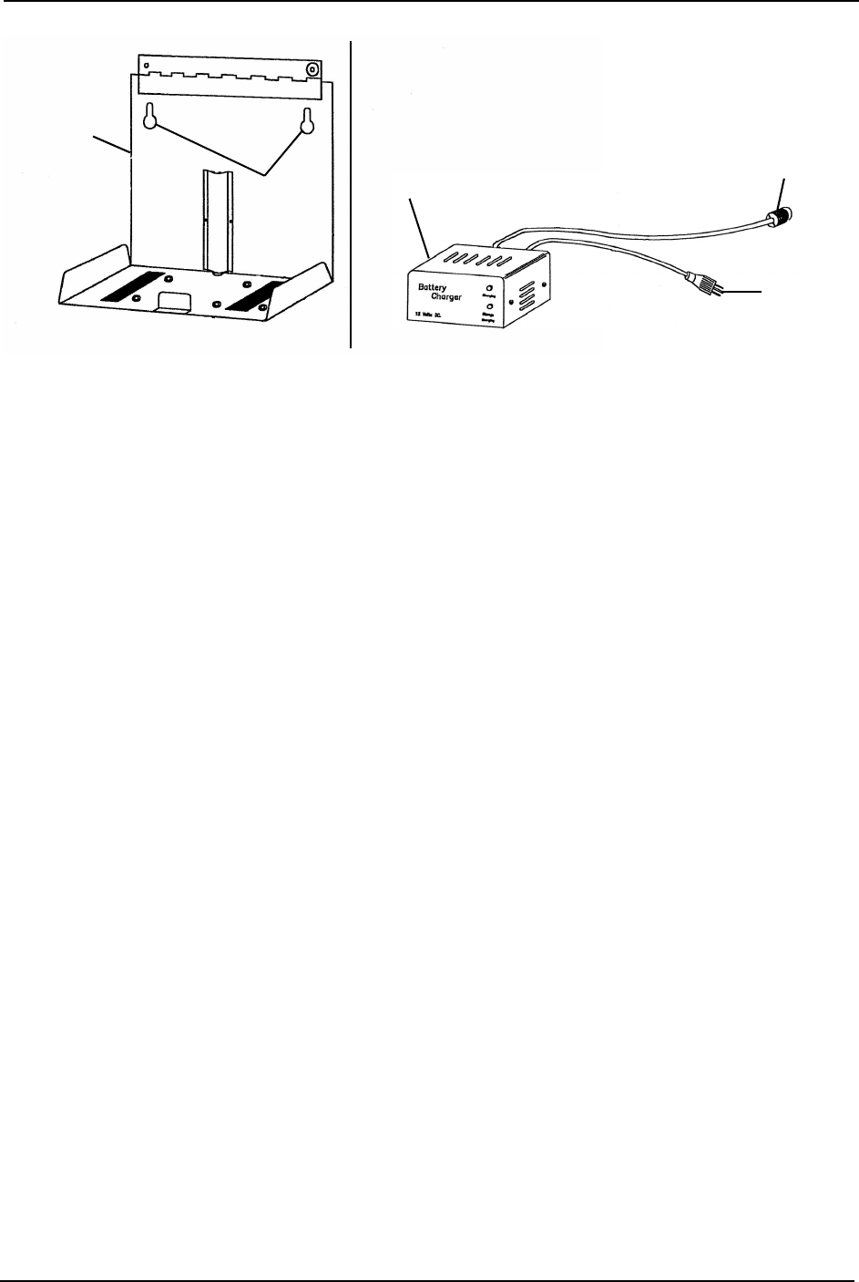
Mounting the Battery Charger
NOTE:Forthisprocedure,refertoFIGURE 2.8.
NOTE:Refertostateandlocalregulationsconcerningpropermountingprocedures.
1. Placethebatterychargermountingbracketonthewallatthedesiredposition.
2. Withapencil,markthemountingholepositions.
3. Installthemountingscrews(notshown)untilthereisanapproximate1/8‐inchgap
betweenthescrewheadandthewall.
4. Installthebatterychargerwithmountingbracketontothemountingscrews.
5. Tightenthemountingscrews(notshown)securely.
6. Plugthebatterychargerpowercordintothewallelectricaloutlet.
NOTE:TheREDandGREENLEDswillilluminate.TheilluminationoftheLEDsindicatesthat
thechargerisoperable.
DETAIL “A” - NON ELECTRONIC SURFACES
Stretcher
Surface
Base
DETAIL “B” - ELECTRONIC SURFACES
Push
Handle
Hand
Pendant
NOTE:Safetystrapsnotshown.
Scale
Arm Rests
Seat
Surface
Base
Push
Handle
Hand
Pendant
Scale
OPERATING THE BATH LIFT
Traverse Lift/Transporter 16 Part No. 1150696
FIGURE 2.8 Mounting the Battery Charger
Charging the Battery
NOTE:Forthisprocedure,refertoFIGURE 2.9onpage17.
Using the Wall-Mounted Battery Charger
1. Liftthebatterylid(Detail“A”).
2. Disconnectthebatteryconnectors.
3. Removethebatteryfromthelift.
4. Liftthelidonthebatterycharger.
5. Positionthebatteryintothebatterycharger.
6. Connectthechargerconnectortothebatteryconnector.
7. Plugthebatterychargerintoapoweroutlet.
8. Chargethebattery.
9. Liftthebatterychargerlid(Detail“A”).
10. Disconnectthechargerconnectorfromthebatteryconnector.
11. Removethebatteryfromthebatterycharger.
12. Installthebatteryintothelift.
13. Connectthebatteryconnectors.
14. Closethebatterylid.
Mounting
Holes
Battery
Charger
Mounting
Bracket
NOTE:Batterychargernotshown.
Battery
Charger
Power
Cord
Charger
Cord
DETAIL “A” -
BATTERY
CHARGER
OPERATING THE BATH LIFT
Traverse Lift/Transporter 18 Part No. 1150696
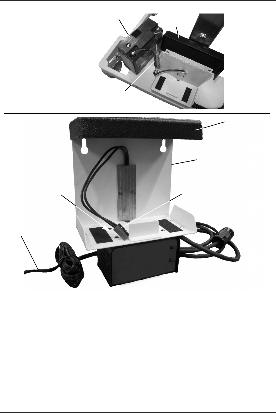
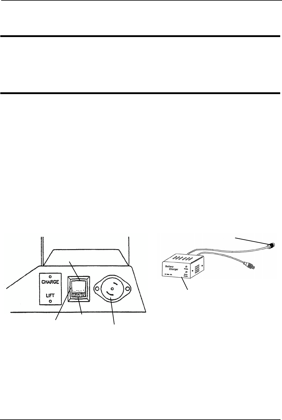
Using the On-Board Battery Charger
NOTE:Forthisprocedure,refertoFIGURE 2.10.
CAUTION
If the charging cord is not locked into the battery charge port the battery will not
charge fully.
Always unplug the charging cord from the battery charge port before wheeling the
lift away. Otherwise, damage to the charging cord will occur.
1. Plugthechargingcordintothebatterychargeportbyperformingthefollowingsteps:
A. Insertthechargingcordintothebatterychargeport.
B. Rotatethechargingcordtolockitintothebatterychargeport.
2. PresstheswitchtotheChargeposition.
3. Plugthebatterychargerintoapoweroutlet.
4. Chargethebattery.
5. Performthefollowingstepstodisconnectthechargingcordfromthebatterycharge
port:
A. Rotatethechargingcordtounlockitfromthebatterychargeport.
B. Removethechargingcordfromthebatterychargeport.
6. PresstheswitchtotheLiftposition.
FIGURE 2.10 Using the On-Board Battery Charger
Battery
Charge Port
Switch LIFT
Position
(Down)
CHARGE Position (Up)
Battery
Charger
Charging Cord

USING THE SCALE
Part No. 1150696 19 Traverse Lift/Transporter
SECTION 3—USING THE SCALE
WARNING
DO NOT attempt any transfer of a resident without approval of the resident's
physician, nurse, or medical assistant. Thoroughly read the instructions in this
owner's manual, observe a trained team of experts performing the lifting
procedures and then perform the entire lift procedure several times with proper
supervision and a capable individual acting as a resident.
ICCI recommends the use of the safety strap and shoulder harness when using the
bath lift. Always adjust the safety strap and shoulder harness for safety and comfort
before transferring the resident onto the chair.
The safety strap should be used when lifting or transferring. Otherwise, the resident
may fall from the seat.
Make adjustments for safety and comfort before moving the resident.
Lock the rear casters of the bath lift when transferring an individual onto the seat or
stretcher. Locking the rear casters will stabilize the lift and help prevent it from
shifting during transfer.
Each facility and each resident will require a unique set of instructions and
procedures to follow for each bath. Check with your supervisor and the resident’s
chart for the proper procedures to follow.
Review and practice the operation with an able bodied assistant before attempting
with a resident.
NOTE:ICCIrecommendsthattwoassistantsbeusedforallliftingpreparationandtransferringto/
fromprocedures;however,thebathliftcanbeoperatedwithoneassistant.Theuseofoneassistant
isbasedontheevaluationofthehealthcareprofessionalforeachindividualcase.
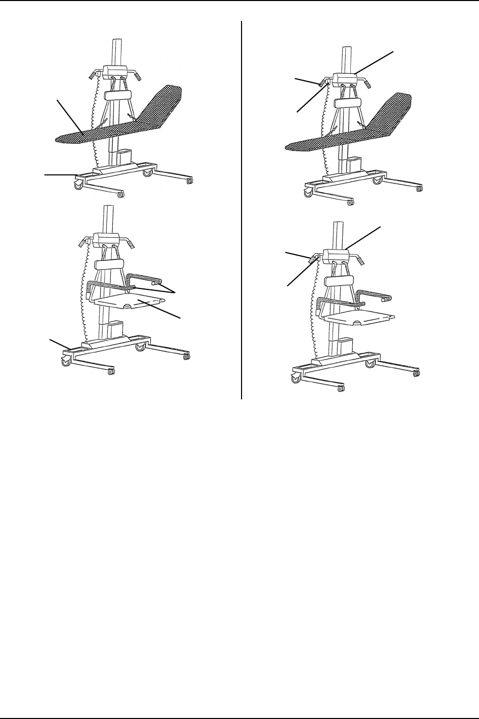
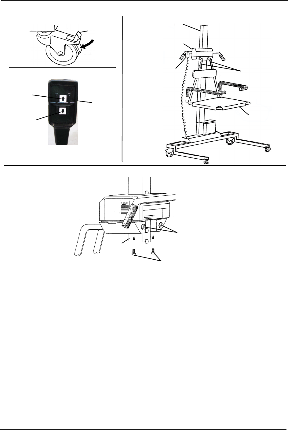
Removing/Installing the Bath Scale
NOTE:Forthisprocedure,refertoFIGURE 3.1onpage20.
NOTE:Toinstallthebathscale,reversethisprocedure.
1. Lockthetworearlockingcastersonthebathliftbypressingdownonthelocking
pedalwithyourfoot(Detail“A”).
2. Pressonthedownarrowonthehandpendanttolowerthebathlift.
3. Removethethreeboltsthatsecurethehangerrodstothebathscale(Detail“D”).
4. Pullthehangerrodsawayfromthepatientscaletoremovetheseatorstretcherfrom
thebathlift.
NOTE:Ifthehandpendantishangingonthesteeringhandle(asshowninDetail“C”,removeit
fromthesteeringhandlebeforeliftingthebathscaleoffoftheliftcolumn.
5. Liftthebathscaleoffoftheliftcolumn.
USING THE SCALE
Traverse Lift/Transporter 20 Part No. 1150696
FIGURE 3.1 Removing/Installing the Bath Scale
Hanger rods
NOTE:Model1300
BathLiftshown.
Lift Column
1100 Bath Scale
(shown in place)
Seat
Hanger Rods
DETAIL “A”
Locking
Pedal
DETAIL “B”
Bolts
DETAIL “C”
Lift
Column
Hand Pendant
Up
Arrow
Down
Arrow
Hand
Pendant
DETAIL “D”
USING THE SCALE
Part No. 1150696 21 Traverse Lift/Transporter
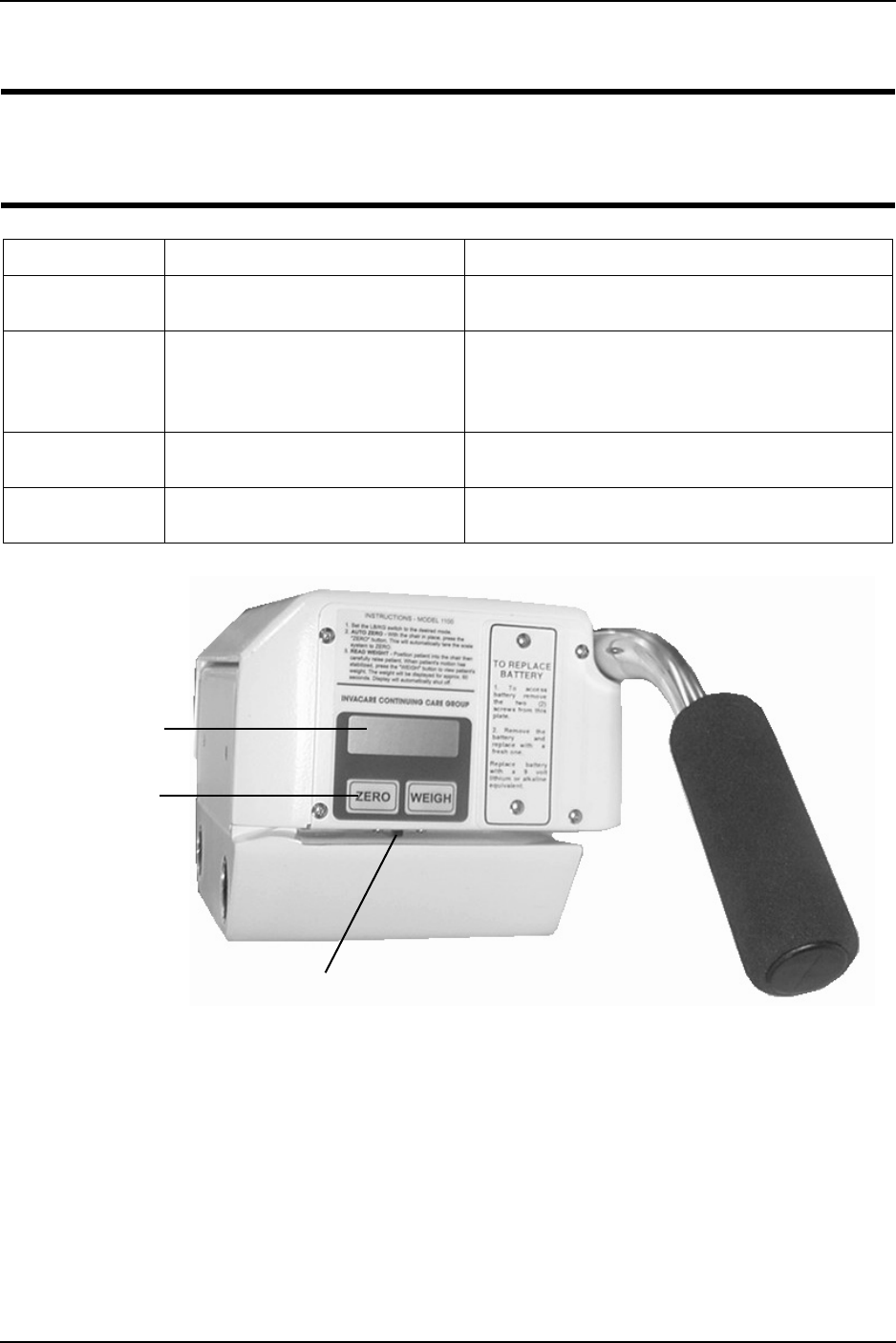
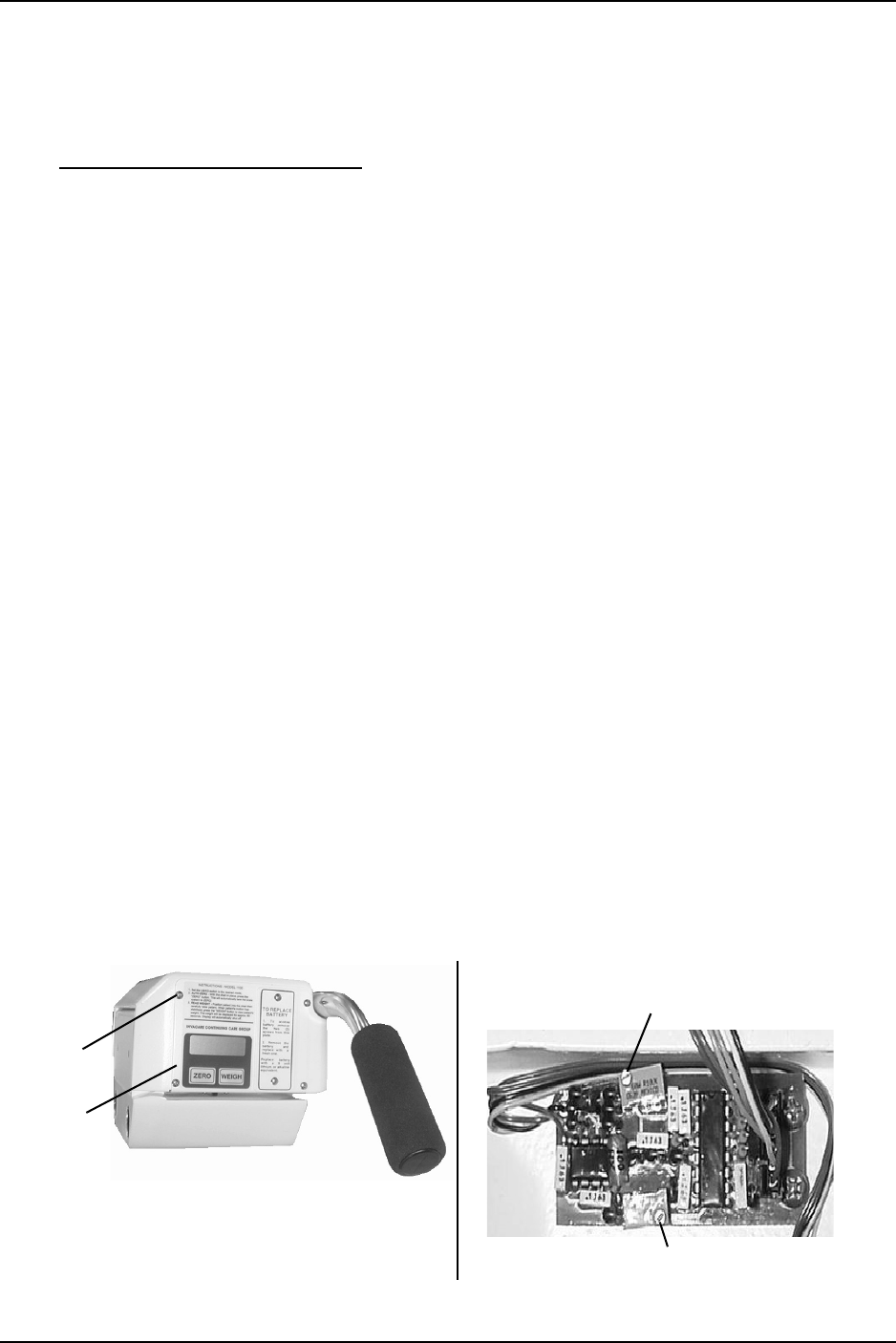
Functions
CAUTION
DO NOT operate keypad with pointed objects (i.e. pencils, pens, fingernails, etc.) -
otherwise damage to the key pad will result.
FIGURE 3.2 1100 Bath Scale
DESCRIPTION LOCATION DEFINITION
ZERO Lower Left below the Display Window Pressing this key when the scale is on will reset the
weight shown in the display window to zero.
WEIGH
Lower Right below the Display Window This key is used to display the patient’s weight value
in the display window.
Note: The patient’s weight will be displayed for approxi-
mately 60 seconds.
LB/KG SWITCH Underneath Display Window Use the LB/KG switch to switch between Pounds and
Kilograms
LOW BATT
INDICATOR
Upper Left Corner of Display
window
“B” will show in the display window to notify when
battery is low.
Display
Window
Keypad
LB/KG Switch
USING THE SCALE
Traverse Lift/Transporter 22 Part No. 1150696
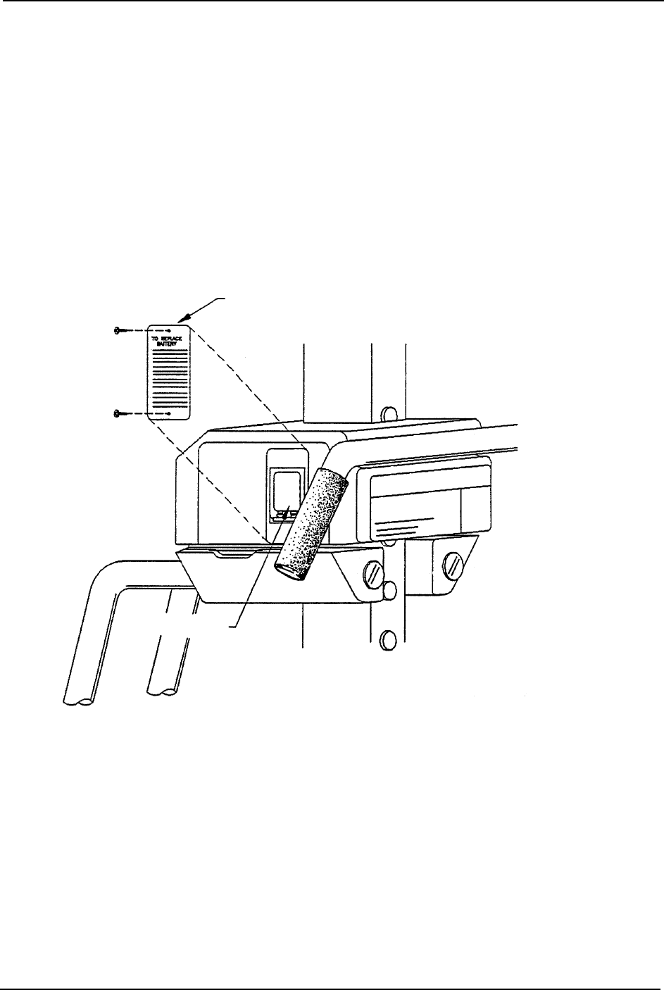
Replacing the Battery
NOTE:Forthisprocedure,refertoFIGURE 3.3.
NOTE:Thescaleispoweredbyaninevoltalkalinebatterythatshouldprovideapproximately3,000
readingsbeforeneedingreplacement.
NOTE:Whenbatteryreplacementisneeded,a“B”willappearintheupperlefthandcornerofthe
displaywindow.
1. Removethetwoscrewsthatattachthebatterycovertothebathscale.
2. Removeandreplacethe9Voltbattery.
3. Attachthebatterycovertothebathscalewithtwoscrews.
FIGURE 3.3 Replacing the Battery
Battery Cover
9 Volt Battery
USING THE SCALE
Part No. 1150696 23 Traverse Lift/Transporter
Calibrating the 1100 Bath Scale
NOTE:Forthisprocedure,refertoFIGURE 3.1onpage20andFIGURE 3.4.
1. ThepatientMUSTberemovedfromthebathlifttoproperlycalibratethebathscale.Refer
toTransferringinto/outoftheLiftoftheBathLiftOwner’sManualforinstructions.
2. Removetheseat/stretcherfromthebathlift.
•Lockthetworearlockingcasters.
•Pressonthedownarrowonthehandpendanttolowerthebathlift.
•Removethethreeboltsthatsecurethehangerrodstothebathscale.
•Pullthehangerrodsawayfromthepatientscaletoremovetheseatorstretcherfrom
thebathlift.
3. Removethefourscrewsthatattachthecovertothebathscale.
NOTE:TheRUN/CALswitchislocatednexttothedisplaywindowandisvisibleafterthecoveris
removed.
4. SlidetheswitchmarkedRUN/CALtotheCALposition.
5. AdjustR9sothedisplayindicates+15poundoffset.RefertoDetail“A ” ofFIGURE3.4.
6. ReverseSTEP2toattachtheseatorstretchertothebathlift.
7. Makenoteoftheweightoftheseatorstretcheronthedisplay.
8. Put200poundsofcalibratedweightontheseatorstretcher.Checkfortheproperweight
increaserelativetotheweightoftheseatorstretchernotedinSTEP7.
9. AdjustR18untiltheweightonthedisplayisaccurateofthecombinedweightofthe
calibratedweightandtheweightoftheseatorstretcher.RefertoDetail“A ” ofFIGURE3.4.
10. Removethecalibratedweightfromthebathscale.RepeatSTEPS5‐9asnecessary.
11. SlidetheRUN/CALswitchtotheRUNposition.PresstheZERObutton.
12. Whenthedisplaywindowreads0.0,placethecalibratedweightontheseatorstretcher
andmakesuretheweightonthedisplayiscorrect.
13. Removethecalibratedweightfromthebathscale.
NOTE:Thebathscaleisreadyforuse.
FIGURE 3.4 Calibrating the 1100 Bath Scale
Screw
(1 of 4)
Cover
R9 Adjustment Screw
R18 Adjustment Screw
DETAIL “A” - 1100 BATH SCALE CIRCUIT BOARD
ADJUSTMENTS
Traverse Lift/Transporter 24 Part No. 1150696
SECTION 4—ADJUSTMENTS
Adjusting the Frame Column Height
NOTE:Forthisprocedure,refertoFIGURE 4.1.
Iftheliftseatorstretchertouchthebottomofthebathingsystemoraretoohighforthe
bathingsystem,usethisproceduretoensuretheframecolumnhasbeenadjustedtothe
properheight.
NOTE:Thebottomoftheseatorthestretchershouldbeapproximatelytwoinchesabovethebottom
ofthebathingsystem.
1. Lowerthelift.RefertoRaising/LoweringtheBathLiftonpage 13.
2. Lockthecasters.RefertoLockingandUnlockingtheCastersonpage 10.
3. StretchersOnly‐Performthefollowingtofoldupbothendsofthestretcher:
A. Pressandholdthebuttononthestretcherframe.
B. Folduptheendofthestretcher.
C. RepeatSTEPSAandBfortheotherendofthestretcher.
4. Pressandholdthereleaselever.
5. Swingthebottomofthestretcherorseatoutandup.
6. Raiseorlowerthestretcherorseatontooneofthesixcolumnstops.
FIGURE 4.1 Adjusting the Frame Column Height
Button
Stretcher Frame
Stretcher End
Stretcher
Column
Stops
Release Lever
Column Stop
Column Stop
ADJUSTMENTS
Part No. 1150696 25 Traverse Lift/Transporter
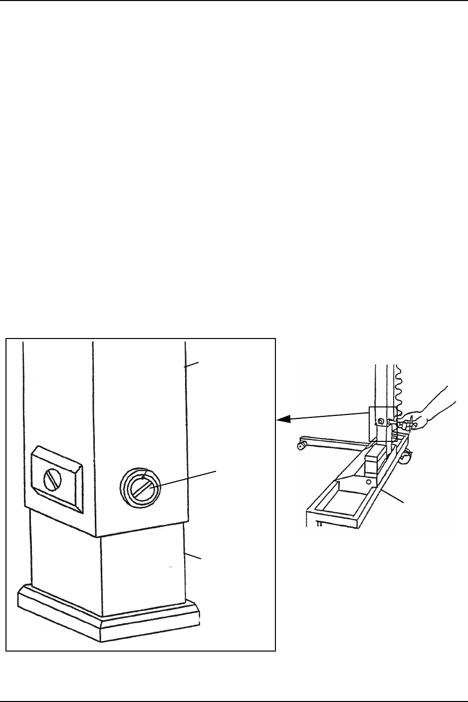
Adjusting the Lift Column
NOTE:Forthisprocedure,refertoFIGURE 4.2.
NOTE:Thenylonbearingscrewsinstalledintheoutercolumnhavebeenadjustedatthefactory
beforeshipping.Theykeeptheoutercolumncenteredaroundtheinnercolumnandprovidea
smoothglideupanddown.Theendsofthenylonbearingscrewscanwearwithuseandshouldbe
checkedperiodically.Approximatelyeverysixmonths,checktheadjustmentofthenylonbearing
screws.
1. Lowerthelifttothefulldownposition.
2. Turnoneofthenylonbearingscrewsuntilthescrewbottomsontheinnercolumn.
3. Backoffthescrew1/8turn.
4. Repeatfortheremaining3nylonbearingscrews.
5. Ensuretheoutercolumnlookscenteredontheinnercolumn.Ifitisnotcentered,
performthefollowingsteps:
A. Loosenonenylonbearingscrew.
B. TightenthenylonbearingscrewdirectlyoppositethescrewloosenedinSTEPA.
C. RepeatStepsAandBuntiltheoutercolumniscenteredontheinnercolumn.
6. Ifthecolumnbindsorchatters,repeatSTEPS1‐5.
FIGURE 4.2 Adjusting the Lift Column
Lift Base
Outer Column
Inner Column
Nylon
Bearing
Screw

MAINTENANCE AND TROUBLESHOOTING
Traverse Lift/Transporter 26 Part No. 1150696
SECTION 5— MAINTENANCE AND
TROUBLESHOOTING
Safety Inspection Checklists
Inspect/Adjust Initially and Monthly
❑Inspectcasterbaseformissinghardware.
❑Ensurethatthecasterbaseislevelandnotrockingoncasters.
❑Inspectthecastersandaxleboltsfortightness.
❑Inspectcastersforsmoothswivelandroll.
❑Ensurethatcastersarefreeofdebris.
❑Inspecttheinnermastforbendsorscrapes.
❑Inspectthearms,hardwareandattachmentpoints.
❑Ensuretheseatarmsliftouttothesides.
❑Ensurethebuttonpositionsstretcherarmsproperly.
❑Ensurethattheseatarmsareleveland/oreven.
❑Ensurethattheelectricactuatorassemblyoperatessmoothlyandquietly.
❑Cleantheliftwhenevernecessary.Regularcleaningwillreveallooseorwornparts,
enhancesmoothoperationandextendthelifeexpectancyofthelift.
❑Inspectallsafetystrapattachmentstoensureproperconnectionandoccupantsafety.
❑Inspectthesafetystrapforsignsofwear.Replaceifwornordamaged.
❑Checkthatalllabelsarepresentandlegible.Replaceifnecessary.
❑Inspectelectricalcomponentsforsignsofcorrosion.Replaceifcorrodedordamaged.
Adjust Every 6 Months
❑Adjusttheframecolumn.RefertoAdjustingtheLiftColumnonpage 25.

MAINTENANCE AND TROUBLESHOOTING
Part No. 1150696 27 Traverse Lift/Transporter
Care and Maintenance of Bath Lift
Theliftsaredesignedtoprovideamaximumofsafe,efficientandsatisfactoryservice
withminimumcareandmaintenance.
Allpartsoftheliftsaremadeofthebestgradesofsteel,butmetal‐to‐metalcontactwill
wearafterconsiderableuse.
Thereisnoadjustmentormaintenanceofeitherthecastersorwheellocks,otherthan
cleaning,lubricationandcheckingaxleandswivelboltsfortightness.Removealldebris,
etc.fromthewheelandswivelbearings.Ifanypartsareworn,replacetheseparts
immediately.
Ifyouquestionthesafetyofanypartofthelift,contactICCIimmediately.
Detecting Wear and Damage
Itisimportanttoinspectallstressedparts.Replaceanydamagedorwornparts
immediatelyandensurethattheliftisnotuseduntilrepairsaremade.
Cleaning the Lift
WARNING
The arms and seat of the lift must be cleaned and disinfected after each use with a
bath. Refer to Disinfecting the Lift on page 14.
1. Asoftcloth,dampenedwithwaterandasmallamountofmilddetergent,wipedown
allpartsoftheliftthataresubmergedinwaterfromthebath.
NOTE:Theliftcanbecleanedwithnon‐abrasivecleanersordisinfectants.
CAUTION
DO NOT use the dryer when laundering the stretcher cover, button cover and
safety straps. Line dry only. Otherwise damage may occur.
2. Removethestretchercover,buttoncoverandsafetystrapsandwashinwarmsoapy
water.Disinfectasnecessary.

MAINTENANCE AND TROUBLESHOOTING
Traverse Lift/Transporter 28 Part No. 1150696
Troubleshooting
NOTE:Ifproblemsarenotremediedbythesuggestedmeans,pleasecontactICCI.
Lift
Scale
SYMPTOMS PROBABLE CAUSE SOLUTIONS
Seat and/or upper column feels loose. Nylon bushing is loose. Refer to Troubleshooting on
page 28.
Casters/brakes noisy or stiff. Fluff or debris in bearings. Clean the or replace the casters.
Electric actuator fails to lift when
button is pressed.
Hand-control or actuator
connector loose.
Battery is low.
Battery not connected properly
to control box.
The connecting terminals are
damaged.
Electric actuator in need of
service or load is too high.
Check connections.
Charge batteries. Refer to Charging
the Battery on page 16.
Reconnect the battery to the
control box. Refer to Charging the
Battery on page 16.
Replace the battery pack. Refer to
Charging the Battery on page 16.
Contact ICCI.
Unusual noise from actuator. Actuator is worn or damaged or
spindle is bent.
Contact ICCI.
SYMPTOMS PROBABLE CAUSE SOLUTIONS
Scale does NOT work properly. Battery failure. Check battery. Replace if necessary.
Battery has been replaced and
scale still does NOT work properly.
Contact ICCI.
ACCESSORIES
Part No. 1150696 29 Traverse Lift/Transporter
SECTION 6—ACCESSORIES
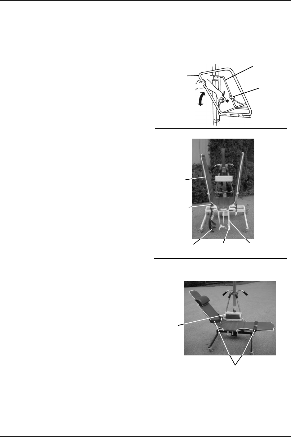
Installing the Stretcher Cover
NOTE:Forthisprocedure,referto
FIGURE 6.1.
NOTE:Thisprocedureappliestothe
IHTRV1210MeshStretcherCover.
1. Pressandholdthebuttonsonthe
stretcherframe(Detail“A”).
2. Raisetherightandleftwingarmsofthe
stretchertoanuprightposition.
3. Alignthestretchercoverwiththe
stretcherframe.
4. Slidethestretchercoverdownoverthe
frame(Detail“B”).
NOTE:Ensurethelongwhitestrapswiththe
maleendsofthebucklesareinthefrontofthe
stretcher.
5. Tuckthecoverdownunderthebutton
knobs.
6. Fastenthethreewhitebucklestosecure
thestretchercovertothestretcher
frame.
7. Fastenthe2‐inchbluestrapsaround
thebottomofthestretcherframe.DO
NOTovertightenthestraps,otherwise
thewingarmswillnotlowersmoothly
totheflatposition.
8. Attachthebuttoncoversecurelyonto
thestretcherframeusingthehookand
loopfasteners(Detail“C”).
9. Attachthesafetystrapsthroughthe
slotsonthebackofthestretchercover
(Detail“C”).
FIGURE 6.1 Attaching the Stretcher Cover
Stretcher
Cover
White Strap
Buckle
Blue Strap
Stretcher
Frame
Button
Wing Arm
Stretcher
Frame
DETAIL “A” - WING ARM
Button
Cover
DETAIL “B” - STRETCHER COVER
DETAIL “C” - BUTTON COVER AND
SAFETY STRAPS
Safety Straps
ACCESSORIES
Traverse Lift/Transporter 30 Part No. 1150696
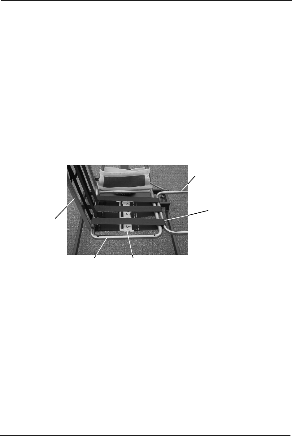
Installing the Short Stretcher Padded Cover
NOTE:Forthisprocedure,referto3.onpage 29,FIGURE 6.2,FIGURE 6.3onpage31,
FIGURE 6.4onpage 31andFIGURE 6.5onpage 32.
NOTE:ThisprocedureappliestothePaddedMeshStretcherCover.
1. Pressandholdthebuttonsonthestretcherframe(Detail“A ” ofFIGURE6.1).
2. Raisetherightandleftendsofthestretchertoanuprightposition.
3. Positionthethreeseatstrapshorizontallyacrosstheseatframe(FIGURE 6.2).
NOTE:Theseatstrapsarelabeledwithan“S”onthebuckle.
4. Attachthethreeseatstrapstotheseatframe.
5. Ensurethebucklesareonthebottomoftheseat.
6. Tightentheseatstrapsuntiltheyaresnug.DONOTovertightenthestraps,otherwise
thewingarmswillnotlowersmoothlytotheflatposition.
FIGURE 6.2 Seat Straps
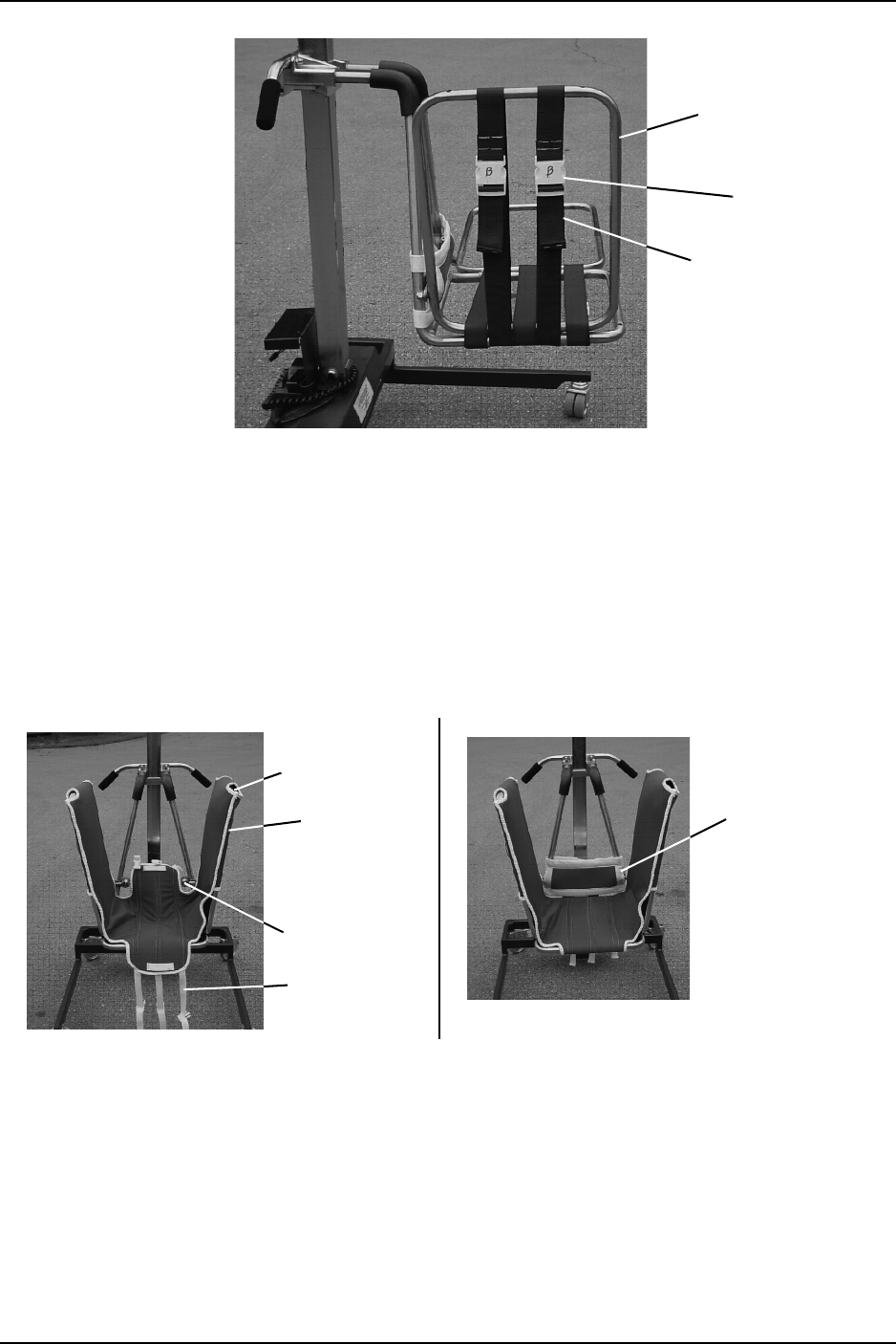
7. Ifnecessary,raisetherightorleftwingarmofthestretchertopreparetheheadend
(FIGURE 6.3).
8. Positionthetwobackstrapsverticallyontotheheadendofthestretcher.
NOTE:Thebackstrapsarelabeledwitha“B”onthebuckle.
9. Attachthetwobackstrapstotheheadendofthestretcher.
10. Ensurethebucklesareontheoutsideofthestretcher.
11. Ensurethetwobackstrapsaretight.
Seat Strap
Seat Frame Buckle
Wing Arm
Wing Arm
ACCESSORIES
Part No. 1150696 31 Traverse Lift/Transporter
FIGURE 6.3 Back Straps
12. Ensurebothstretcherwingarmsareraised(Detail“A ” ofFIGURE 6.4).
13. Positionthestretchercoversothewhitebeltstrapsareinthefrontoftheseat.
14. Slidethestretchercoveroverthestretcherframe.
15. Tuckthestretchercoverdownunderthebuttonsonthestretcherframe.
16. Fastenthethreewhitebucklesundertheseat.
17. Attachthebackbuttoncoveroverthebuttonsusingthestraps.
FIGURE 6.4 Positioning the Cover/Button Cover
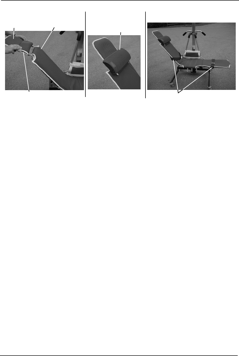
18. Locatetheheadendofthestretcher(Detail“A ” ofFIGURE 6.5).
19. Slidethepaddedmeshcoverovertheheadsupportandattachtotheheadendofthe
stretcher.
20. Attachthemeshcoveredpillowtotheheadsupport(Detail“B”ofFIGURE6.5).
21. Attachthesafetystrapsthroughtheslotsonthebackofthestretchercover(Detail“C”
ofFIGURE6.5).
Head End of the
Stretcher
Buckle
Back Strap
Wing Arm
Stretcher
Cover
White Strap
Button
DETAIL “A” DETAIL “B”
Button Cover


LIMITED WARRANTY
Part No. 1150696 35 Traverse Lift/Transporter
LIMITED WARRANTY
PLEASE NOTE: THE WARRANTY BELOW HAS BEEN DRAFTED TO COMPLY WITH FEDERAL
LAW APPLICABLE TO PRODUCTS MANUFACTURED AFTER JULY 4, 1975.
This warranty is extended only to the original purchaser/user of our products.
This warranty gives you specific legal rights and you may also have other legal rights which vary from
state to state.
Invacare Continuing Care, Inc. (ICCI) warrants this product to be free from defects in materials and
workmanship on the lift and the electric components for a period of one year from the date of
purchase. If within such warranty period any such component shall be proven to be defective, such
component shall be repaired or replaced, at ICCI’s option. This warranty does not include any labor
or shipping charges incurred in replacement part installation or repair of any such product. ICCI’s
sole obligation and your exclusive remedy under this warranty shall be limited to such repair and/or
replacement.
For warranty service, please contact the dealer from whom you purchased your ICCI product. In the
event you do not receive satisfactory warranty service, please write directly to ICCI at the address
on the back cover, provide dealer’s name, address, date of purchase, indicate nature of the defect.
ICCI will issue a serialized return authorization. The defective unit or parts MUST be returned for
warranty inspection using the serial number, when applicable as identification within 30 days of
return authorization date. DO NOT return products to our factory without our prior consent.
C.O.D. shipments will be refused; please prepay shipping charges.
LIMITATIONS AND EXCLUSIONS: THE FOREGOING WARRANTY SHALL NOT APPLY TO
SERIAL NUMBERED PRODUCTS IF THE SERIAL NUMBER HAS BEEN REMOVED OR DEFACED,
PRODUCTS SUBJECTED TO NEGLIGENCE, ACCIDENT, IMPROPER OPERATION,
MAINTENANCE OR STORAGE, PRODUCTS MODIFIED WITHOUT ICCI’S EXPRESS WRITTEN
CONSENT (INCLUDING, BUT NOT LIMITED TO, MODIFICATION THROUGH THE USE OF
UNAUTHORIZED PARTS OR ATTACHMENTS; PRODUCTS DAMAGED BY REASON OF
REPAIRS MADE TO ANY COMPONENT WITHOUT THE SPECIFIC CONSENT OF ICCI, OR TO
A PRODUCT DAMAGED BY CIRCUMSTANCES BEYOND ICCI’S CONTROL, AND SUCH
EVALUATION WILL BE SOLELY DETERMINED BY ICCI. THE WARRANTY SHALL NOT APPLY
TO PROBLEMS ARISING FROM NORMAL WEAR OR FAILURE TO ADHERE TO THE
INSTRUCTIONS IN THIS MANUAL.
THE FOREGOING WARRANTY IS EXCLUSIVE AND IN LIEU OF ANY OTHER EXPRESS
WARRANTIES. IMPLIED WARRANTIES, IF ANY, INCLUDING THE IMPLIED WARRANTIES OF
MERCHANTABILITY AND FITNESS FOR A PARTICULAR PURPOSE, SHALL NOT EXTEND
BEYOND THE DURATION OF THE EXPRESSED WARRANTY PROVIDED HEREIN AND THE
REMEDY FOR VIOLATIONS OF ANY IMPLIED WARRANTY SHALL BE LIMITED TO REPAIR OR
REPLACEMENT OF THE DEFECTIVE PRODUCT PURSUANT TO THE TERMS CONTAINED
HEREIN. ICCI SHALL NOT BE LIABLE FOR ANY CONSEQUENTIAL OR INCIDENTAL
DAMAGES WHATSOEVER.
SOME STATES DO NOT ALLOW EXCLUSION OR LIMITATION OF INCIDENTAL OR
CONSEQUENTIAL DAMAGE, OR LIMITATION ON HOW LONG AN IMPLIED WARRANTY
LASTS, SO THE ABOVE EXCLUSIONS AND LIMITATIONS MAY NOT APPLY TO YOU.
THIS WARRANTY SHALL BE EXTENDED TO COMPLY WITH STATE OR PROVINCIAL LAWS
AND REQUIREMENTS.

www.invacare-ccg.com
USA and Canada
One Invacare Way
Elyria, Ohio USA
44036-2125
800-333-6900
Manufacturing Location
899 Cleveland Street
Elyria, Ohio USA
44036-2125
All rights reserved. Trademarks are identified
by the symbols ™ and ®. All trademarks are
owned by or licensed to Invacare
Corporation or its subsidiaries unless
otherwise noted.
©2009 Invacare Corporation
Invacare Continuing Care, Inc.
A subsidiary of Invacare Corporation.
Part No. 1150696 Rev A - 01/09
For customer service, call 800-668-2337.
