Invacare Wheelchair Arrow Users Manual
Arrow to the manual c03ff111-b32a-4c70-af51-704344e66270
2015-02-02
: Invacare Invacare-Invacare-Wheelchair-Arrow-Users-Manual-433639 invacare-invacare-wheelchair-arrow-users-manual-433639 invacare pdf
Open the PDF directly: View PDF ![]() .
.
Page Count: 108 [warning: Documents this large are best viewed by clicking the View PDF Link!]

Service Manual
STORM SERIES®
WHEELCHAIRS
(RWD/MWD/FWD)
Arrow®
Torque SP
Ranger X
DEALER: KEEP THIS MANUAL. THE PROCEDURES
IN THIS MANUAL MUST BE PERFORMED BY AN
AUTHORIZED DEALER ONLY

2
WARNING
W
A
R
N
I
N
G
SAVE THESE INSTRUCTIONS
WARNING
THE PROCEDURES IN THIS MANUAL SHOULD ONLY BE PERFORMED BY
QUALIFIED TECHNICIAN.
DO NOT SERVICE OR OPERATE THIS EQUIPMENT WITHOUT FIRST
READING AND UNDERSTANDING THIS MANUAL AND THE OWNERS
MANUAL SUPPLIED WITH THE WHEELCHAIR. IF YOU ARE UNABLE TO
UNDERSTAND THE WARNINGS, CAUTIONS, AND INSTRUCTIONS,
CONTACT INVACARE TECHNICAL SUPPORT BEFORE ATTEMPTING TO
SERVICE OR OPERATE THIS EQUIPMENT - OTHERWISE INJURY OR
DAMAGE MAY RESULT.
SPECIAL NOTES
WARNING/CAUTION notices as used in this manual apply to hazards or unsafe practices
which could result in personal injury or property damage.
NOTICE
THE INFORMATION CONTAINED IN THIS DOCUMENT IS SUBJECT TO CHANGE WITHOUT
NOTICE.
WHEELCHAIR USER
As a manufacturer of wheelchairs, Invacare endeavors to supply a wide variety of
Action wheelchairs to meet many needs of the end user. However, final selection of
the type of wheelchair to be used by an individual rests solely with the user and his/her
healthcare professional capable of making such a selection.
WHEELCHAIR TIE-DOWN RESTRAINTS AND SEAT POSITIONING STRAPS
Invacare recommends that wheelchair users NOT be transported in vehicles of any
kind while in wheelchairs. As of this date, the Department of Transportation has not
approved any tie-down systems for transportation of a user while in a wheelchair, in a
moving vehicle of any type.
It is Invacare’s position that users of wheelchairs should be transferred into appropri-
ate seating in vehicles for transportation and use be made of the restraints made
available by the auto industry. Invacare cannot and does not recommend any wheel-
chair transportation systems.
AS REGARDS RESTRAINTS - SEAT POSITIONING STRAPS - IT IS THE OBLIGATION OF THE DME
DEALER, THERAPISTS AND OTHER HEALTHCARE PROFESSIONALS TO DETERMINE IF A SEAT-
ING POSITIONING STRAP IS REQUIRED TO ENSURE THE SAFE OPERATION OF THIS EQUIP-
MENT BY THE USER. SERIOUS INJURY CAN OCCUR IN THE EVENT OF A FALL FROM A WHEEL-
CHAIR.
S
P
E
C
I
A
L
N
O
T
E
S

3
TABLE OF CONTENTS
T
A
B
L
E
O
F
C
O
N
T
E
N
T
S
NOTE: The information in this owner's manual applies to the STORM ARROW, ** STORM TORQUE, STORM
X, JUNIOR MODELS and the RECLINER Wheelchairs except where specified.
NOTE: Procedures 1- 14 apply to rear wheel drive, mid wheel drive and front wheel drive wheelchairs EXCEPT
where specified.
SPECIAL NOTES ...................................................................................................................................................... 2
SPECIFICATIONS ..................................................................................................................................................... 6
PROCEDURE 1 - GENERAL GUIDELINES .................................................................................................................... 8
REPAIR OR SERVICE INFORMATION .................................................................................................................. 8
OPERATING INFORMATION ................................................................................................................................8
WARNING/CAUTION LABEL LOCATION ............................................................................................................. 9
PROCEDURE 2 - TROUBLESHOOTING ..................................................................................................................... 11
FIELD LOAD TEST ........................................................................................................................................... 11
USING HYDROMETER TO CHECK BATTERY CELLS (LEAD ACID) ....................................................................... 11
MOTOR TESTING ............................................................................................................................................ 12
MOTOR BRUSH INSPECTION ........................................................................................................................... 13
ELECTRO-MECHANICAL PARKING BRAKE TESTING ......................................................................................... 13
PROCEDURE 3 - HARDWARE TORQUE SPECIFICATIONS ......................................................................................... 14
STANDARD SEAT FRAME ................................................................................................................................14
CAPTAINS VAN SEAT ...................................................................................................................................... 15
ADJUSTABLE SEAT FRAME ............................................................................................................................. 15
REAR WHEEL DRIVE BASE FRAME HARDWARE TORQUE SPECIFICATIONS ..................................................... 16
MID-WHEEL DRIVE BASE FRAME HARDWARE TORQUE SPECIFICATIONS ........................................................ 17
FRONT WHEEL DRIVE BASE FRAME HARDWARE TORQUE SPECIFICATIONS ............................................... 18
PROCEDURE 4 - ARMS ........................................................................................................................................... 19
REPLACING ARMREST PADS - CAPTAINS VAN SEAT ........................................................................................ 19
REPLACING CAPTAINS VAN SEAT ARMREST PLATE ......................................................................................... 19
PROCEDURE 5 - UPHOLSTERY/POSITIONING STRAP .............................................................................................. 20
REPLACING SEAT POSITIONING STRAP - CAPTAINS VAN SEATS ....................................................................... 20
REPLACING BACK UPHOLSTERY .................................................................................................................... 20
PROCEDURE 6 - SEAT FRAME ................................................................................................................................22
PREPARATIONS FOR REMOVING/INSTALLING SEAT FRAME (STANDARD FRAME, ADJUSTABLE FRAME AND
CAPTAINS VAN SEAT ...................................................................................................................................... 22
REPLACING EXACT SAME SIZE STANDARD SEAT FRAME ................................................................................ 23
REMOVING/INSTALLING STANDARD SEAT FRAME SUB-ASSEMBLY .................................................................. 23
CHANGING SEAT DEPTH ................................................................................................................................. 24
CHANGING SEAT WIDTH (STANDARD AND ADJUSTABLE SEAT FRAME) ............................................................. 26
INSTALLING/REMOVING ADJUSTABLE SEAT FRAME SUBASSEMBLY AND/OR COMPONENT REPLACEMENT ..... 27
INSTALLING/REMOVING CAPTAINS VAN SEAT ASSEMBLY ............................................................................. 29
REPLACING CAPTAINS VAN SEAT AND/OR CAPTAINS VAN SEAT FRAME ...................................................... 29
CONVERTING FROM STANDARD SEAT FRAME TO ADJUSTABLE SEAT FRAME OR VICE VERSA ................... 30
CONVERTING FROM ADJUSTABLE SEAT FRAME TO CAPTAINS VAN SEAT OR VICE VERSA .......................... 30
CONVERTING FROM STANDARD SEAT FRAME TO CAPTAINS VAN SEAT OR VICE VERSA ............................. 31
REMOVING/INSTALLING SEAT PAN ................................................................................................................. 31
MOUNTING PLATE - SEAT ANGLE ADJUSTMENT AND INSTALLATION ORIENTATION ........................................ 32
PROCEDURE 7 - BASE FRAME ................................................................................................................................33
REPLACING SEAT MOUNTING PLATES ............................................................................................................. 33
REPLACING SEAT SUPPORT BRACKETS ......................................................................................................... 33
REPLACING SEAT SUPPORT BRACKET T-NUTS ............................................................................................... 34
REPLACING BATTERY CHARGER BRACKET AND T-NUT .................................................................................... 35
REMOVING/INSTALLING SEAT STOP SCREWS ................................................................................................. 36
PROCEDURE 8 - BACK FRAME ................................................................................................................................37
REPLACING CJ BACK BRACKETS .................................................................................................................... 37
CHANGING BACK HEIGHT ............................................................................................................................... 38
BACK ANGLE ADJUSTMENT ............................................................................................................................ 40
TABLE OF CONTENTS
** The Storm Torque model wheelchair is available in rear wheel drive ONLY.

4
TABLE OF CONTENTS
TABLE OF CONTENTS (Continued)
PROCEDURE 9 - BATTERIES ................................................................................................................................. 41
INSTALLING/REMOVING BATTERIES INTO/FROM BATTERY BOX(ES) ............................................................... 41
CONNECTING BATTERY CABLES ................................................................................................................... 42
WHEN TO CHARGE BATTERIES ..................................................................................................................... 46
CHARGING BATTERIES .................................................................................................................................. 46
REPLACING BATTERIES ................................................................................................................................. 48
INSTALLING/REMOVING GROUP 24 BATTERY BOXES .................................................................................... 48
INSTALLING/REMOVING GROUP 22 BATTERY BOX ......................................................................................... 49
PROCEDURE 10 - WIRING HARNESS ...................................................................................................................... 50
REMOVING/INSTALLING THE WIRING HARNESS .............................................................................................. 50
ADJUSTING LIMIT SWITCH .............................................................................................................................. 52
PROCEDURE 11 - RETENTION STRAP/RETAINER ................................................................................................. 53
REPLACING BATTERY BOX RETAINER/RETAINER CLIP - GROUP 24 BATTERY BASE FRAMES ........................... 53
PROCEDURE 12 - WHEELS/MOTORS ................................................................................................................... 54
REPLACING PNEUMATIC TIRES/TUBES - DRIVE WHEELS/CASTERS ................................................................. 55
REMOVING/INSTALLING DRIVE WHEELS ........................................................................................................... 55
REMOVING/INSTALLING DRIVE WHEEL HUB ..................................................................................................... 56
INSTALLING WHEEL LOCK BRACKET ONTO WHEEL CHAIR ............................................................................... 56
REMOVING/INSTALLING CASTERS .................................................................................................................... 57
REPLACING FORKS .......................................................................................................................................... 57
REMOVING/INSTALLING THE MOTOR (CONVENTIONAL MOTOR WITH GEARBOX) .............................................. 57
REMOVING/INSTALLING THE MOTOR (GEARLESS BRUSHLESS MOTOR) .......................................................... 59
PROCEDURE 13 - ELECTRONICS ......................................................................................................................... 61
REPOSITIONING MKIV JOYSTICK - VAN SEAT MODELS ..................................................................................... 61
REMOVING/INSTALLING MKIV CONTROLLER ..................................................................................................... 61
PROCEDURE 14 - RECLINER ................................................................................................................................63
POSITIONING LIMIT SWITCH ............................................................................................................................... 63
ADJUSTING LIMIT SWITCH ................................................................................................................................. 63
REPLACING RECLINER CABLE ASSEMBLIES .................................................................................................... 64
REPLACING/ADJUSTING GAS CYLINDERS ......................................................................................................... 65
CHANGING BACK HEIGHT ................................................................................................................................. 66
CHANGING SEAT DEPTH ................................................................................................................................... 67
CHANGING SEAT WIDTH ................................................................................................................................... 67
EQUIPMENT OPTION INSTALLING/REPLACING ADJUSTABLE 16 TO 19-INCH DEEP RECLINER SEAT FRAME ONTO
ARROW OR X BASE FRAME .......................................................................................................................... 68
PROCEDURE 15 - MWD WHEELCHAIRS ............................................................................................................... 69
REMOVING/INSTALLING GROUP 24 BATTERY BOX SUB-FRAME ........................................................................ 69
REMOVING/INSTALLING GROUP 22 BATTERY BOX TRAY ................................................................................... 69
EQUIPMENT OPTION CONVERTING GROUP 22 BATTERY BOX TRAY TO GROUP 24 BATTERY BOX SUB FRAME ..... 70
SHOCK REPLACEMENT .................................................................................................................................... 71
SHOCK SPRING REPLACEMENT ....................................................................................................................... 73
REPLACING STABILIZER FORK ASSEMBLY ....................................................................................................... 74
REPLACING STABILIZER WHEELS ..................................................................................................................... 74
REPLACING STABILIZER CYLINDER SPRING ...................................................................................................... 75
ADJUSTING WEIGHT DISTRIBUTION ................................................................................................................... 75
ADJUSTING STABILIZERS .................................................................................................................................. 76
REMOVING/INSTALLING GEARBOX .................................................................................................................... 77
REPLACING SUSPENSION ARM ........................................................................................................................ 77
T
A
B
L
E
O
F
C
O
N
T
E
N
T
S

5
PROCEDURE 16 - RWD WHEELCHAIRS ............................................................................................................... 79
REMOVING/INSTALLING GROUP 24 BATTERY BOX SUB-FRAME ........................................................................ 79
REMOVING/INSTALLING GROUP 22 BATTERY BOX TRAY ................................................................................... 79
EQUIPMENT OPTION CONVERTING GROUP 22 BATTERY BOX TRAY TO GROUP 24 BATTERY BOX SUB FRAME .... 80
SHOCK REPLACEMENT .................................................................................................................................... 81
SHOCK SPRING REPLACEMENT ....................................................................................................................... 83
RUBBER ELEMENT REPLACEMENT - TORQUE AND X BASE FRAMES .............................................................. 84
EQUIPMENT OPTION CONVERTING TORQUE AND X RUBBER ELEMENTS TO SHOCKS .................................... 84
REMOVING/INSTALLING GEARBOX .................................................................................................................... 85
ADJUSTING WEIGHT DISTRIBUTION ................................................................................................................... 85
REPOSITIONING MOTOR/GEARBOX .................................................................................................................. 86
REPOSITIONING THE GEARLESS/BRUSHLESS MOTOR .................................................................................... 87
REPLACING SUSPENSION ARM FOR WHEELCHAIRS WITH MOTOR/GEARBOX ASSEMBLY .............................. 88
REPLACING THE SUSPENSION ARM FOR WHEELCHAIRS WITH GEARLESS/BRUSHLESS MOTOR ................... 89
ANTI-TIPPER WHEEL REPLACEMENT ................................................................................................................ 89
REMOVING INSTALLING THE ANTI-TIP ASSEMBLY ............................................................................................. 90
PROCEDURE 17 - FWD WHEELCHAIRS ...................................................................................................................... 91
REMOVING/INSTALLING REAR SHROUD .................................................................................................................. 91
REMOVING/INSTALLING FRONT SHROUD ................................................................................................................ 91
REMOVING/INSTALLING SIDE SHROUD ASSEMBLY ................................................................................................ 91
REMOVING/INSTALLING COUNTERWEIGHT ............................................................................................................. 92
REPLACING GROUP 24 BATTERY BOX SUB-FRAME ............................................................................................... 93
REMOVING/INSTALLING SHOCKS ............................................................................................................................. 94
SHOCK SPRING REPLACEMENT .............................................................................................................................. 95
TIE ROD REPLACEMENT .......................................................................................................................................... 95
REMOVING/INSTALLING GEARBOX .......................................................................................................................... 96
SENSOR CABLE ASSEMBLY REPLACEMENT ......................................................................................................... 97
REPLACING SUSPENSION ARM ............................................................................................................................... 98
REMOVING/INSTALLING WIRING HARNESS ............................................................................................................. 99
ADJUSTING WEIGHT DISTRIBUTION ....................................................................................................................... 101
INSTALLING 90O FOOTBOARD ................................................................................................................................. 101
FOOTBOARD ADJUSTMENTS - DEPTH/HEIGHT/ANGLE ......................................................................................... 102
FOOTREST ANGLE ADJUSTMENTS ........................................................................................................................ 103
LIMITED WARRANTY ................................................................................................................................................. 107
TABLE OF CONTENTS (Continued)
TABLE OF CONTENTS
T
A
B
L
E
O
F
C
O
N
T
E
N
T
S

6
S
P
E
C
I
F
I
C
A
T
I
O
N
S
SPECIFICATIONS
SPECIFICATIONS
* in 1-inch increments
** Storm Torque/Torque SP model wheelchairs are available in rear wheel drive ONLY. Gearless Brushless Motor Option is
available on Storm Torque ONLY.
✪With MKIV RII Controller. ● With MKIV Rx or A Controller. u Non-Recliners ONLY.
vArrow specifications refer to RWD, MWD and FWD wheelchairs except where specified.
vARROW ** TORQUE **TORQUE SP X JUNIOR
Seat Width Range:
250 lbs Rating ✪ 16 to 20-in. *12 to 16-in.
MWD/RWD
300 lbs. Rating *16 to 22-in. 16 and 18-in. ● 16 to 20-in *16 to 22-in.
MWD/RWD FWD
400 lbs. Rating *19 to 24-in. *16 to 24-in.
Seat Depth Range: *16 to 22-in. 16 and 18-in. *16 to 18-in. *16 to 22-in. *12 to 15-in. w/CJ Back
Expandable to - *16 to 17-in.
Back Height Range: *16 to 24-in. 16, 18, 20,22-in. *16 to 22-in. *16 to 24-in. *12 to 18-in.
Seat-to-Floor
(approximate) MWD/RWD FWD Storm Base X Base
Standard: 17-1/2-in. 18-1/4-in. 17-1/2-in. 17-1/2-in. 17-1/2-in. 17-1/2-in. 17-1/2-in.
Optional: 19-3/4-in. 20-1/2-in. 19-3/4-in. 19-3/4-in. 19-3/4-in. 19-3/4-in. 19-3/4-in.
21-in. 21-3/4-in. N/A N/A 21-in.
Overall Width
of Base: 24-5/8-in. 25-1/4-in. 24-5/8-in. 24-5/8-in. 24-5/8-in.
(w/o joystick)
Overall Height MWD/RWD FWD Storm Base X Base
Standard: 34-1/4-in. 35-1/2-in 34-1/4-in. 34-1/4-in. 34-1/4-in. 34-1/4-in. 34-1/4-in.
Minimum: 34-1/4-in. 35-1/2-in N/A N/A 34-1/4-in. 32-1/4-in. 32-1/4-in.
Maximum: 44-1/4-in. 45-1/2-in N/A N/A 44-1/4-in. 40-1/2-in. 40-1/2-in.
Recliner - (Std.)
Low Seat Frame: 51-1/2-in. 52-3/4-in. N/A N/A 51-1/2-in. N/A
Med. Seat Frame: 53-3/4-in. 55-in. N/A N/A 53-1/4-in. N/A
High Seat Frame: 55-1/2 in. 58-1/2-in. N/A N/A 55-1/2-in. N/A
Overall Length
(without front
riggings) MWD/RWD FWD
Standard: 32-1/4-in. 35-1/4-in 32-1/4-in. 32-1/4-in. 32-1/4-in. 32-1/4-in.
Long Frame: 35-1/4-in. N/A N/A N/A 35-1/4-in. 35-1/4-in.
Weight
Standard Motor MWD/RWD FWD Storm Base X Base
W/O Batteries: 146 lbs. 199 lbs. 149 lbs. 149 lbs. 149 lbs. 146 lbs. 149 lbs.
W/Batteries:
Standard 248 lbs. 310 lbs. 224 lbs. 224 lbs. 224 lbs. 246 lbs. 224 lbs.
Optional N/A N/A 249 lbs. N/A 249 lbs. N/A 249 lbs.
Shipping (approx.): 176 lbs. 229 lbs. 176 lbs. 176 lbs. 176 lbs. 176 lbs. 176 lbs.
Gearless/Brushless
Motor
W/O Batteries: 166 lbs. N/A 169 lbs. N/A 169 lbs. 166 lbs. 169 lbs.
W/ Batteries:
Standard 243 lbs. N/A 243 lbs. N/A 243 lbs. 266 lbs. 243 lbs.
Optional 268 lbs. N/A 268 lbs. N/A 268 lbs. N/A 268 lbs.
Shipping (approx.): 196 lbs. N/A 196 lbs. N/A 196 lbs. 196 lbs. 196 lbs.
Drive Axle: *◆Adjustable (MWD/RWD only) *◆Adjustable *◆Adjustable *◆Adjustable *Adjustable
Drive Wheels/Tires:
(Foam Filled or
Pneumatic)
Standard: 14 X 3-in. 14 X 3-in. 14 X 3-in. 14 X 3-in. 14 X 3-in. 14 X 3-in.
Optional: 14 X 4-in. 14 X 4-in. 14 X 4-in. 14 X 4-in. 14 X 4-in. 14 X 4-in.
PHYSICAL
DIMENSIONS

7
SPECIFICATIONS
S
P
E
C
I
F
I
C
A
T
I
O
N
S
PHYSICAL DIMENSIONS vARROW ** TORQUE **TORQUE SP X JUNIOR
Casters w/Precision Sealed Bearings
Semi-Pneumatic 300 lbs. Rating
Standard: 8 X 1-3/4-in. 8 X 1-3/4-in. 8 X 1-3/4-in. 8 X 1-3/4-in. 8 X 1-3/4-in.
Option: 6 X 2-in. 6 X 2-in. 6 X 2-in. 6 X 2-in. 6 X 2-in.
Pneumatic or Foam Filled
Standard: 8 X 2-in. 8 X 2-in. 8 X 2-in. 8 X 2-in. 8 X 2-in.
Option: 9 X 2-3/4-in. 9 X 2-3/4-in. 9 X 2-3/4-in.
Pneumatic or Foam Filled 400 lbs. Rating
(RWD,MWD only)
Standard: 9 X 2-3/4-in.
Option: 8 X 2-in.
SPECIFICATIONS (Continued)
PERFORMANCE ARROW **TORQUE **TORQUESP X JUNIOR
Speed 0 to 5-3/4 (300 lbs. rating) RWD,MWD 0 to 6-1/2 0 to 4-1/4 0 to 6-1/2 Arrow Base X Base
(M.P.H.): 0 to 4-1/4 (400 lbs. rating) RWD,MWD 0 to 6-1/2 0 to 6-1/2
*0 to 7-1/4 (300 lbs. rating)RWD,MWD *0 to 7-1/4 *0 to 7-1/4 *0 to 7-1/4 *0 to 7-1/4
0 to 4 (400 lbs. rating) FWD
***Range(miles): up to 19 - RWD,MWD up to 16 (Std) Up to 16 up to 16 (Std) up to 19 up to 23 (Std)
(uGel Batteries) *up to 29 (Std) - RWD,MWD up to 19 (Opt) up to 19 (Opt) *up to 29 (Std) up to 19 (Opt)
*up to 29 (Opt) - RWD,MWD *up to 29 (Std) *up to 29 (Std) *up to 35 (Opt) *up to 29 (Std)
up to 16 - FWD *up to 35 (Std) *up to 35 (Opt) up to 35 (Opt)
Weight 300 lbs. (Standard Unit); 400 lbs. (FWD) 300 lbs. ✪ 250 lbs. 300 lbs. 250 lbs. 250lbs.
Limitation: *300 lbs. (Standard Unit)RWD,MWD *300 lbs. ● 300 lbs.
400 lbs. (Heavy Duty Unit) RWD,MWD *300 lbs.
vARROW, ** TORQUE, **TORQUE SP, X and JUNIOR
Anti-Tippers (3-inch wheels): Standard (N/A on FWD)
Caster Forks: Standard, Shock Fork (Optional)
Footrest: Telescoping Front Rigging Supports, Swing-Away (Standard),
Heavy Duty (Optional), 4-inch Longer Pivot Slide Tube (Optional)
Armrests: Flip Back, Fixed or Adjustable Height (Desk and Full Length)
Seat Angle Adjustment: Adjustable (0o to 10o)
Back Angle Adjustment: Adjustable (80o to 100o in 5o increments)
Seat Cushion: Cushion (Optional)
Chair Upholstery Options: Naugahyde and Nylon
Battery/Size (Not Supplied): BASE FRAMES uSTD BATTERIES uOPT BATTERIES
Two (2) Required Arrow w/ Standard motor Group 24 N/A
(uGel Batteries) - w/ **Gearless/Brushless motor Group 22 Group 24
Torque w/ Standard Motor Group 22 Group 24
- w/ Gearless/Brushless motor Group 22 Group 24
**Torque SP w/ Standard Motor Group 22 N/A
Ranger X w/Standard Motor Group 22 Group 24
- w/ Gearless/Brushless motor Group 22 Group 24
NOTE: Information below is unique to the Recliner. Refer to Arrow, X , Torque, and Torque SP for complete specifications.
RECLINER Widths Depths Back Heights Weight Limits (LBS.) Back Angle Range
14 to 24-in. 16 to 22-in. 18-1/2 to 26-in. Arrow Base -300 Std./400 Optional 90o to 170o
✪ Torque SP Base - 250
X, Torque,● Torque SP Base - 300
Arrow, X, Torque Base W/ Gearless/
Brushless Motor - 300 lbs.
* With gearless/brushless motor option.
** Storm Torque/Torque SP wheelchairs are available in rear
wheel drive ONLY. Gearless Brushless Motor Option is avail-
able on Storm Torque ONLY.
***Range will vary with battery conditions,
surface, terrain and operators weight.
✪ With MKIV RII Controller.
● With MKIV Rx or A Controller.
v Arrow specifications refer to RWD, MWD and FWD wheel-
chairs except where specified.
Arrow FWD has a 400 lb. rating.

8
GENERAL GUIDELINESPROCEDURE 1
G
E
N
E
R
A
L
G
U
I
D
E
L
I
N
E
S
REPAIR OR SERVICE INFORMATION
Set-up of the Electronic Control Unit is to be performed ONLY by individuals certified by
Invacare. The final tuning adjustments of the controller may affect other activities of
the wheelchair. Damage to the equipment could occur under these circumstances. If
non-certified individuals perform any work on these units, the warranty is void.
OPERATING INFORMATION GENERAL WARNINGS
Performance adjustments should only be made by professionals of the healthcare field
or persons fully conversant with this process and the driver's capabilities. Incorrect set-
tings could cause injury to the driver, bystanders, damage to the chair and to surrounding
property.
After the wheelchair has been set-up, check to make sure that the wheelchair performs
to the specifications entered during the set-up procedure. If the wheelchair does NOT
perform to specifications, turn the wheelchair OFF immediately and reenter set-up speci-
fications. Repeat this procedure until the wheelchair performs to specifications.
DO NOT use parts, accessories, or adapters other than those authorized by Invacare.
TIRE PRESSURE
DO NOT use your wheelchair unless it has the proper tire pressure (P.S.I.). DO NOT overin-
flate the tires. Failure to follow these suggestions may cause the tire to explode and
cause bodily harm. The recommended tire pressure is listed on the side wall of the tire.
ELECTRICAL
Grounding Instructions:
DO NOT, under any circumstances, cut or remove the round grounding prong from any
plug used with or for Invacare products. Some devices are equipped with three-prong
(grounding) plugs for protection against possible shock hazards. Where a two-prong wall
receptacle is encountered, it is the personal responsibility and obligation of the customer
to contact a qualified electrician and have the two-prong receptacle replaced with a
properly grounded three-prong wall receptacle in accordance with the National Elec-
trical Code. If you must use an extension cord, use ONLY a three-wire extension cord
having the same or higher electrical rating as the device being connected. In addition,
Invacare has placed RED/ORANGE WARNING TAGS on some equipment. DO NOT re-
move these tags. Carefully read battery/battery charger information prior to installing,
servicing or operating your wheelchair.
BATTERIES
The warranty and performance specifications contained in this manual are based on
the use of deep cycle gel cell or sealed lead acid batteries. Invacare strongly
recommends their use as the power source for this unit.
Battery connecting cables are NOT interchangeable. Battery connecting cables with
single fuse setup MUST only be used on wheelchairs with conventional motor/gearbox
assembly. Otherwise, damage may result. Refer to INSTALLING/REMOVING BATTERIES
INTO/FROM BATTERY BOX(ES) in PROCEDURE 9 of this manual.
This Procedure Includes the Following:
Repair or Service Information
Operating Information
9
GENERAL GUIDELINES PROCEDURE 1
G
E
N
E
R
A
L
G
U
I
D
E
L
I
N
E
S
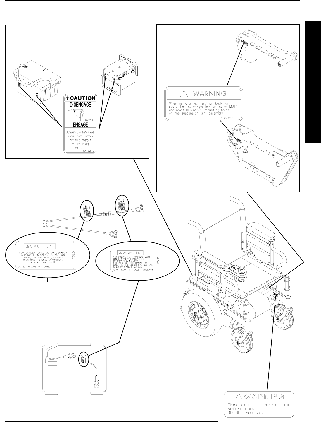
WARNING/CAUTION LABEL LOCATION - RWD MODELS
SUSPENSION ARM USED
WITH GEARLESS/BRUSHLESS
MOTOR
NOTE: WARNING LABEL also
found on side frame near the rear
of the chair.
SUSPENSION ARM
USED
WITH CONVENTIONAL
MOTOR/GEARBOX
ASSEMBLY
NOTE: These caution labels are only found on bat-
tery boxes used with the gearless/brushless motor
GROUP 24 BATTERIES GROUP 22 BATTERIES
NOTE: This caution label is only
found on wiring harnesses used
with the conventional motor/gear-
box application.
ONE (1) CONNECTOR BATTERY
BOX WIRING HARNESS
NOTE: For models with the gearless/brushless motor, read the
manufacturers CAUTION LABEL located on side of the motor.
(Drive wheel must be removed to view caution label.)
NOTE: This wiring harness is found on wheel-
chair models built BEFORE 11/15/99.
NOTE: This wiring harness is found on
wheelchair models built AFTER 11/15/99.
1070497
MUST
10
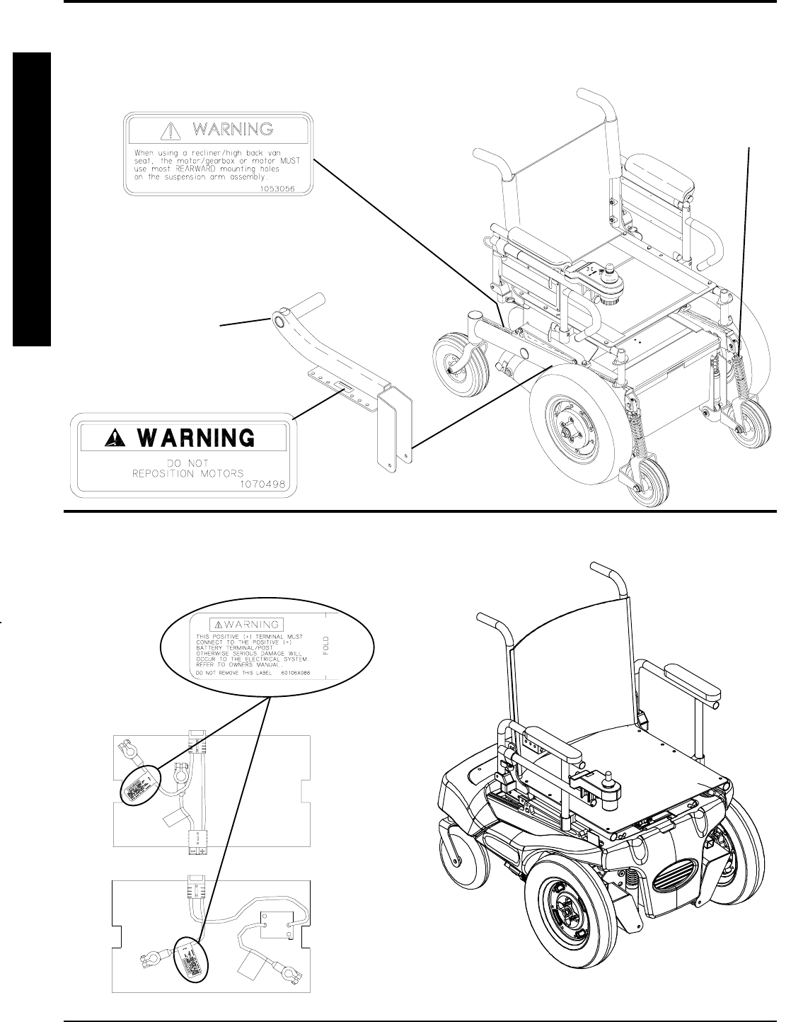
MWD MODELS
Suspension Arm
(located on inside of
drive wheel)
NOTE: CAUTION LABEL also
found on side frame near the front
of the chair.
GENERAL GUIDELINESPROCEDURE 1
G
E
N
E
R
A
L
G
U
I
D
E
L
I
N
E
S
WARNING/CAUTION LABEL LOCATION
BATTERY BOX WIRING HARNESS
FWD MODELS
NOTE: Stablilizer springs
are found on models built
BEFORE 7/11/99 ONLY.
11
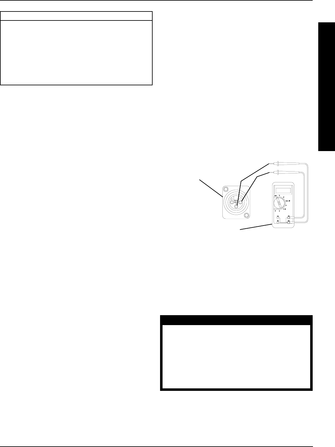
(+)
(-)
FIGURE 1 - FIELD LOAD TEST
Battery Charger
Connector
Digital Voltmeter
FIELD LOAD TEST (FIGURE 1)
NOTE: The following test can also be performed through
the controller of the wheelchair along with a remote pro-
grammer. Refer to the individual CONTROLLER
MANUAL supplied with each wheelchair.
Old batteries lose their ability to store and release power, due
to increased internal resistance. This means that as you try
to take power from the battery, some of that power is used up
in the process of passing through the battery, resulting in less
voltage at the posts. The more power drawn, the lower the
voltage available. When this lost voltage drops the output 1.0
volts under load (2.0 for a pair), replace the batteries.
Testing under load is the only way to spot this problem.
While special battery load testing equipment is available,
it is costly and difficult to transport.
Use a digital voltmeter to check battery charge level at the charger
connector. It is located on the base of the wheelchair frame.
NOTE: READ the instructions CAREFULLY before us-
ing the digital voltmeter.
NOTE: Invacare recommends that ONLY qualified ser-
vice personnel perform this test.
1. Ensure that power is OFF.
2. Make sure battery is fully charged. An extremely dis-
charged battery will exhibit the same symptoms as a
bad one.
3. Remove the footrests from the wheelchair and per-
form one (1) of the following:
A. RWD MODELS - place the CASTERS of the
wheelchair against a wall, workbench or other
stationary object.
B. MWD MODELS - place the STABILIZER
wheels of the wheelchair against a wall, work-
bench or other stationary object.
C. FWD MODELS -place the DRIVE wheels of
the wheelchair against a wall, workbench or
other stationary object.
USING HYDROMETER TO CHECK
BATTERY CELLS (LEAD ACID)
(FIGURE 2)
NOTE: Perform this procedure when a digital voltmeter is
not available.
WARNING
NEVER smoke or strike a match near the
batteries. If the caps of the battery cells
are removed, NEVER look directly into
them when charging the battery.
The use of rubber gloves and chemical
goggles or face shields is recommended
when working with batteries.
TROUBLESHOOTING PROCEDURE 2
This Procedure Includes the Following:
Field Load Test
Using Hydrometer To Check Battery Cells (Lead
Acid)
Motor Testing
Motor Brush Inspection
Electro-Mechanical Parking Brake Testing
4. Place the voltmeter leads into the charger plug on the
wheelchair. Most digital voltmeters are not affected by
polarity, however, analog meters (meters with swing-
ing needles) can be and should be used carefully. A
good meter reading should be 25.5 to 26 VDC.
5. Have two (2) individuals (one [1] on each arm) apply
as much downward pressure as possible on the arms
of the wheelchair.
6. Turn the wheelchair ON and push the joystick for-
ward, trying to drive the wheelchair through the sta-
tionary object. This puts a heavy load on the batteries
as they try to push through the stationary object. Read
the meter while the motors are straining to determine
the voltage under load.
NOTE: If the voltage drops to less than 23.5 volts from a
pair of fully charged batteries while under load, they should
be replaced regardless of the unloaded voltages.
T
R
O
U
B
L
E
S
H
O
O
T
I
N
G

12
TROUBLESHOOTING
PROCEDURE 2
T
R
O
U
B
L
E
S
H
O
O
T
I
N
G
WARNING
When reading a hydrometer, DO NOT al-
low any liquid to come in contact with
your eyes or skin. It is a form of acid and
can cause serious burns, and in some
cases, blindness. If you do get battery acid
on you, flush the exposed areas with cool
water IMMEDIATELY. If the acid comes into
contact with eyes or causes serious burns,
get medical help IMMEDIATELY.
The battery acid can damage your wheel-
chair, clothing, and household items.
Therefore, take readings cautiously and
only in designated areas.
ONLY use distilled water when topping off
the battery cells.
Most batteries are not sold with instructions.
However, warnings are frequently noted
on the cell caps. Read them carefully.
1. Remove the battery box(es). Refer to INSTALLING/
REMOVING BATTERY BOXES - GROUP 24 BAT-
TERY BASE FRAMES or INSTALLING/REMOVING
BATTERY BOX - GROUP 22 BATTERY BASE
FRAMES in PROCEDURE 9 of this manual.
2. Remove the battery caps from the battery.
3. Squeeze the air from the hydrometer.
4. Place the hydrometer into a battery cell.
NOTE: DO NOT fill hydrometer more than 3/4 full.
5. Draw up sufficient acid to cover float balls.
6. Tap lightly to remove air bubbles.
7. Number of floating balls indicates charge.
Number of Floating Balls
0 Discharged
1 25% Charged
2 50% Charged
3 75% Charged
4 100% Charged
* 5 Overcharged
* Check charging system.
8. Flush the liquid back into the same cell after reading
the float. Repeat this step until all cells have been prop-
erly read. A shorted or dead cell can be detected when
it is the only cell that does not charge.
FIGURE 2 - USING HYDROMETER TO CHECK
BATTERY CELLS (LEAD ACID)
Number of Floating
Balls Will Vary
According to Charge
9. Flush hydrometer in cold running water by allowing
the water to rise into hydrometer as far as possible.
Do this several times to guard against burn damage.
10. Replace the battery caps.
11. Reinstall battery boxes. Refer to INSTALLING/RE-
MOVING BATTERY BOXES - GROUP 24 BATTERY
BASE FRAMES or INSTALLING/REMOVING BAT-
TERY BOX - GROUP 22 BATTERY BASE FRAMES
in PROCEDURE 9 of this manual.
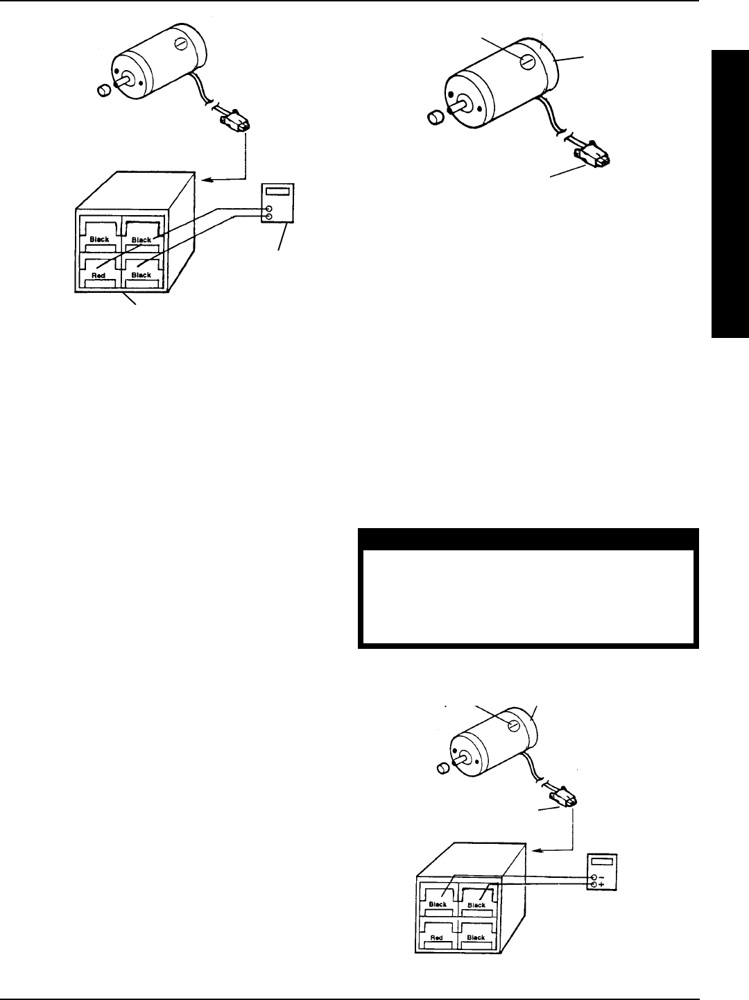
MOTOR TESTING (FIGURE 3)
NOTE: This procedure should only be performed on
wheelchairs with the conventional motor/gearbox assem-
bly. For gearless/brushless motors, there are no service-
able parts. Return motor to manufacturer for testing.
1. On the 4-pin motor connector, locate the two (2) con-
tacts in the red and black housings.
2. Set the digital multimeter to measure ohms (Ω).
3. Measure the resistance between the two (2) motor
contacts.
NOTE: A normal reading is between 1 and 5 ohms
(Ω). A reading of 0 ohms (Ω) or in excess of 15 ohms
(Ω) indicates a problem. High readings are generally
caused by bad connections and/or damaged brushes.
Contact authorized dealer or Invacare.
TROUBLESHOOTING
13
ELECTRO-MECHANICAL PARKING
BRAKE TESTING (FIGURE 5)
NOTE: This procedure should only be performed on
wheelchairs with conventional motor/gearbox assembly.
1. On the four-pin motor connector, locate the side by
side connectors in the black housings.
2. Set the digital multimeter to read ohms (Ω).
3. Measure the resistance between the two (2) brake con-
tacts. A normal reading is 100 ohms (Ω). A reading of 0
ohms (Ω) or a very high reading; i.e., MEG ohms or O.L.
(out of limit) indicates a shorted brake or an open connec-
tion respectively. If either condition exists, send the motor
to Invacare Technical Service for inspection/repair.
CAUTION
A shorted electro-mechanical brake will
damage the brake output section in the con-
troller. DO NOT connect a shorted electro-
mechanical brake to a good controller mod-
ule. A shorted brake MUST be replaced.
NOTE: A bad motor can damage the controller module
but a bad controller will NOT damage a motor.
4 Pin Motor Connector
Ohmmeter
Cap Motor
Cap
4 Pin Motor Connector
Motor
FIGURE 5 - ELECTRO-MECHANICAL
PARKING BRAKE TESTING
MOTOR BRUSH INSPECTION
(FIGURE 4)
NOTE: This procedure should only be performed on wheel-
chairs with conventional motor/gearbox assembly.
There are two (2) contact brushes on ACTION STORM mo-
tors located under the brush caps on the motor housing. If
these caps are hard to remove they are either overtightened or
the motor has become very hot. Let motors cool. If caps still
cannot be removed, it is recommended that the motor be sent
to Invacare Technical Services for inspection/repair.
NOTE: It is very important to note which way the brush
comes out of the motor. The brush MUST be placed into
the motor exactly the same way to ensure good contact
with the commutator.
1. Once the motor brush caps have been removed, pull
the brushes out of the motor. The end of the brushes
should be smooth and shiny and the spring should
not be damaged or discolored. If one or both of the
brushes are damaged, only the damaged or worn
brushes need be replaced. It is very important that
any time a brush is replaced, it must be burned in.
This is accomplished by running the motor for one
hour in each direction with a half hour break in-be-
tween. This should also be done with little or no load
on the motor, i.e., put the wheelchair up on blocks so
the drive (large) wheels do not contact the ground
and run the wheelchair. A motor with only one brush
replaced will only carry a small percentage of its rated
load capacity until the NEW brush is burned in.
FIGURE 4 - MOTOR BRUSH INSPECTION
T
R
O
U
B
L
E
S
H
O
O
T
I
N
G
TROUBLESHOOTING PROCEDURE 2
FIGURE 3 - MOTOR TESTING
Motor Connector
Ohmmeter
Motor Connector
Ohmmeter
14
PROCEDURE 3 HARDWARE TORQUE SPECIFICATIONS
T
O
R
Q
U
E
S
P
E
C
I
F
I
C
A
T
I
O
N
S
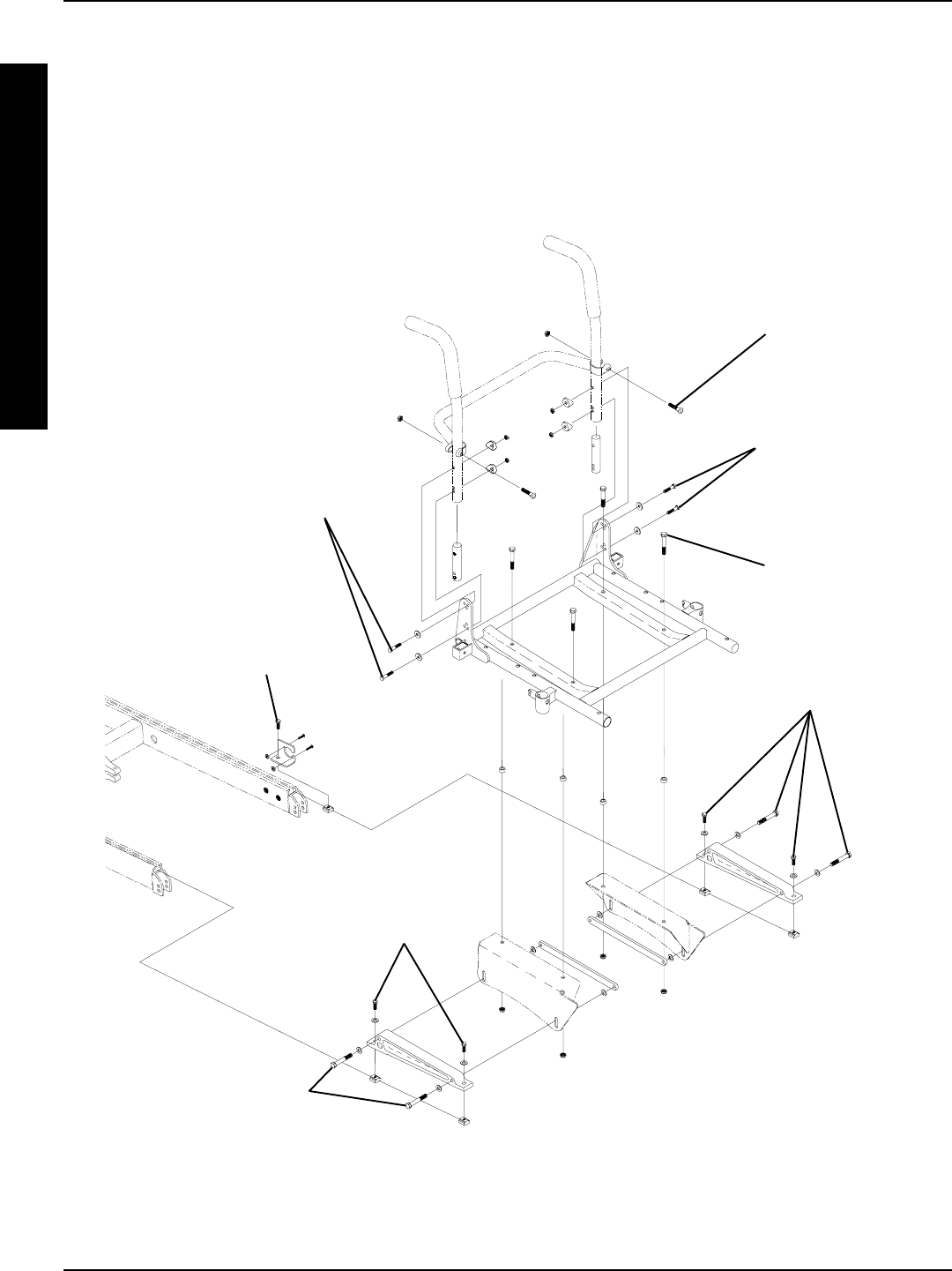
HARDWARE TORQUE SPECIFICATIONS
*Torque to
60 in/lbs
**Torque
to
156 in/lbs
Torque to
156 in/lbs
**Torque to
156 in/lbs
**Torque to
156 in/lbs
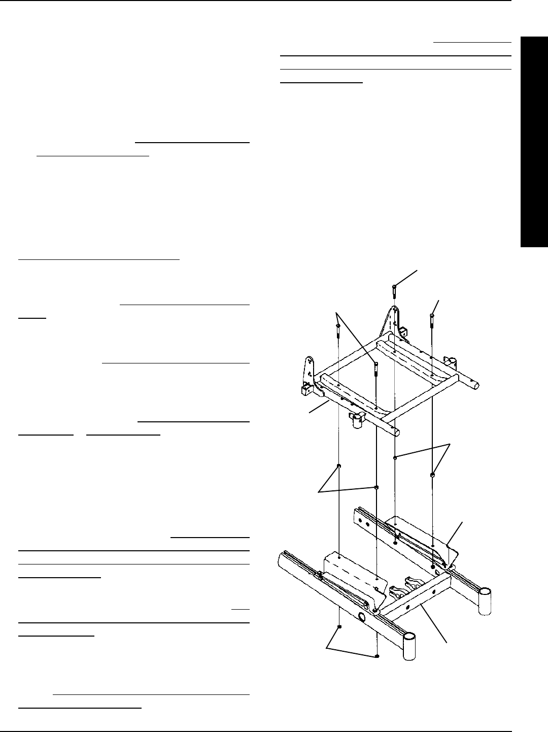
STANDARD SEAT FRAME
*Loctite® and
Torque to
75 in/lbs
*Loctite and
Torque to
75 in/lbs
**Torque to
156 in/lbs
NOTE:
* These torque specifications also apply to the adjustable seat frame assembly.
** These torque specifications also apply to the captains van seat and adjustable seat frame assemblies.

15
T
O
R
Q
U
E
S
P
E
C
I
F
I
C
A
T
I
O
N
S
PROCEDURE 3HARDWARE TORQUE SPECIFICATIONS
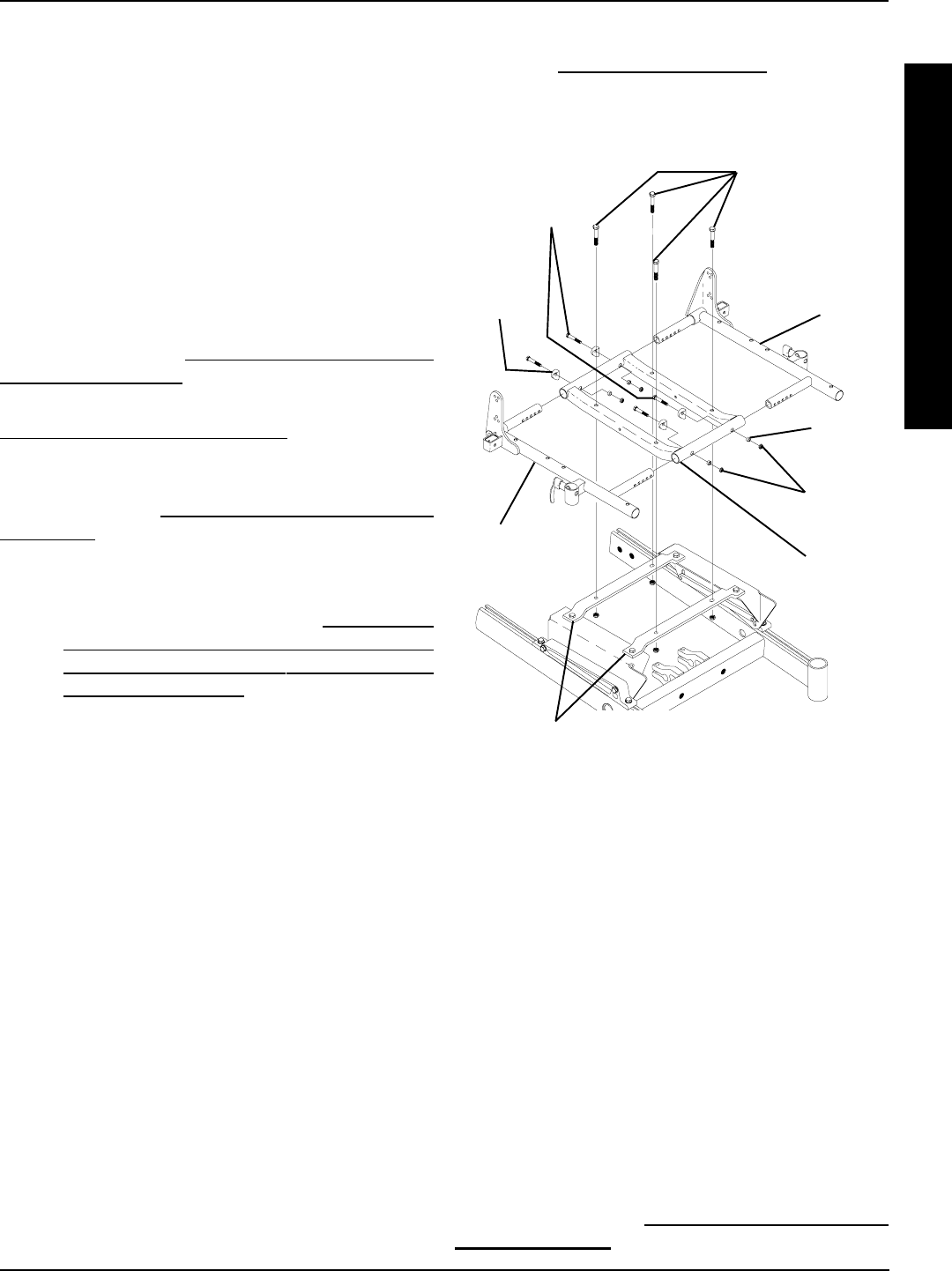
Torque to
75-in/lbs
HARDWARE TORQUE SPECIFICATIONS
*CAPTAINS VAN SEAT
Loctite and Torque to
75 in/lbs
Torque to
156 in/lbs
*ADJUSTABLE SEAT FRAME
Torque to
156 in/lbs
Torque to
156-in/lbs Torque to
156-in/lbs
Torque to
156-in/lbs
Torque to
156-in/lbs
* NOTE: For additional torque specifications, refer to the torque specifications drawing for the standard
seat frame assembly.
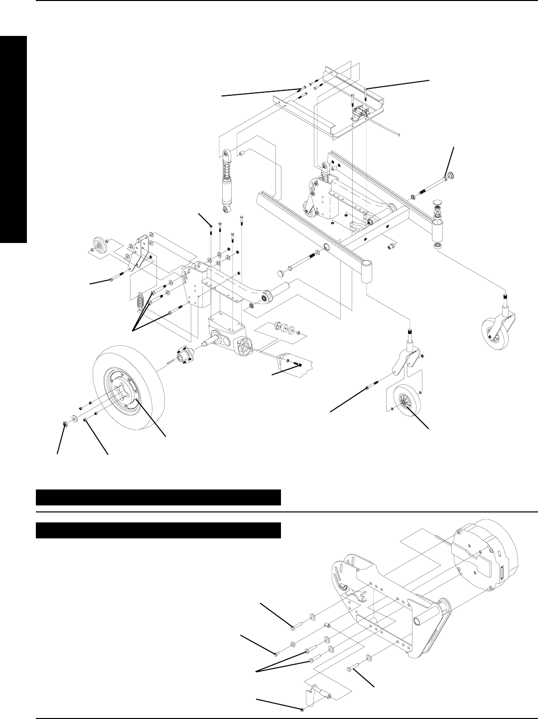
16
Torque to
160 in/lbs
Loctite and torque to
160 in/lbs
Torque to
1020 in/lbs
8 - inch Wheels -
Torque to 120 in/lbs
9 - inch Wheels -
Torque to 160 in/lbs
Torque to
160 in/lbs
Loctite and
torque to
75 in/lbs
Tighten until snug
Pneumatic with Flat-Free
Wheel Halves - Torque to
160 in/lbs
Pneumatic Wheel Halves -
8 - inch - Torque to 18 in/lbs
9 - inch - Torque to 160 in/lbs
Loctite and
Torque to
75 in/lbs
Torque to
160 in/lbs
Torque to
160 in/lbs
Wheel Halves -
Torque to 75 in/lbs
FRONT OF
WHEELCHAIR
REAR OF
WHEELCHAIR
PROCEDURE 3 HARDWARE TORQUE SPECIFICATIONS
T
O
R
Q
U
E
S
P
E
C
I
F
I
C
A
T
I
O
N
S
REAR WHEEL DRIVE BASE FRAME HARDWARE
TORQUE SPECIFICATIONS
GEARLESS/BRUSHLESS MOTOR
Torque to 13 ft/lbs.
Torque to 13 ft/lbs.
Torque to 13 ft/lbs.
Torque to 25 in/lbs.
Torque to 75 in/lbs.
CONVENTIONAL MOTOR/GEARBOX
NOTE: All torque specifications called out for the con-
ventional motor/gearbox assembly are applicable to
the gearless/brushless motor except for the following:
17
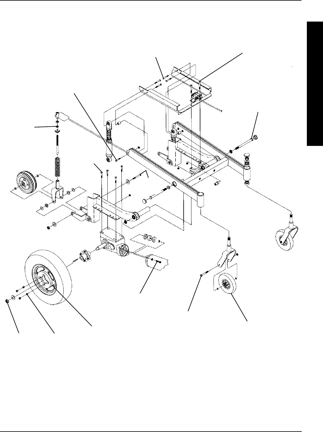
MID-WHEEL DRIVE BASE FRAME HARDWARE
TORQUE SPECIFICATIONS
Torque to
160 in/lbs
Torque to
1020 in/lbs
Loctite and
Torque to
75 in/lbs
Torque to
160 in/lbs
Torque to
160 in/lbs
Torque to
160 in/lbs
Loctite and
torque to
75 in/lbs
Tighten
until snug
Torque to
40 in/lbs
Loctite and torque to
160 in/lbs
FRONT OF
WHEELCHAIR
REAR OF
WHEELCHAIR
8 - inch Wheels -
Torque to 120 in/lbs
9 - inch Wheels -
Torque to 160 in/lbs
Pneumatic with Flat-Free
Wheel Halves - Torque to 160
in/lbs
Pneumatic Wheel Halves -
8 - inch - Torque to 18 in/lbs 9 -
inch - Torque to 160 in/lbs
Wheel Halves -
Torque to 75 in/lbs
T
O
R
Q
U
E
S
P
E
C
I
F
I
C
A
T
I
O
N
S
PROCEDURE 3HARDWARE TORQUE SPECIFICATIONS
18
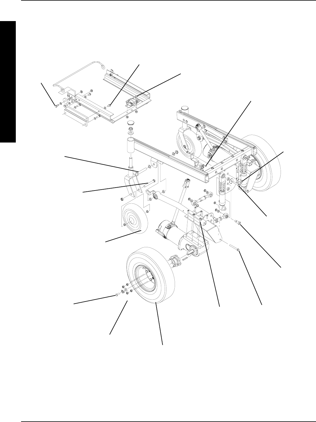
FRONT-WHEEL DRIVE BASE FRAME HARDWARE
TORQUE SPECIFICATIONS
T
O
R
Q
U
E
S
P
E
C
I
F
I
C
A
T
I
O
N
S
Torque to
1020 in/lbs
Torque to
156 in/lbs
Torque to
156 in/lbs
Torque to
156 in/lbs
Torque to
15 in/lbs
Torque to
360 in/lbs
Torque to
156 in/lbs
Torque to
360 in/lbs
Torque to
156 in/lbs
Loctite and
Torque to
75 in/lbs FRONT OF
WHEELCHAIR
REAR OF
WHEELCHAIR
Torque to
160 in/lbs
8 - inch Wheels -
Torque to 120 in/lbs
9 - inch Wheels -
Torque to 160 in/lbs
Pneumatic with Flat-Free
Wheel Halves - Torque to 160
in/lbs
Pneumatic Wheel Halves -
8 - inch - Torque to 18 in/lbs
9 - inch - Torque to 160 in/lbs
Wheel Halves -
Torque to 75 in/lbs
PROCEDURE 3 HARDWARE TORQUE SPECIFICATIONS
Torque to
160 in/lbs
19
A
R
M
S
ARMS PROCEDURE 4
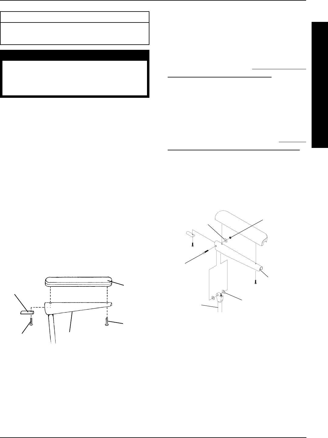
REPLACING ARMREST PADS -
CAPTAINS VAN SEATS (FIGURE 1)
1. Remove the mounting screws that secures the front
of the armrest pad to the armrest plate.
2. Remove the mounting screw that secures the rear of
the armrest pad and armrest insert to the armrest
plate.
3. Remove the existing armrest pad and position the
NEW armrest pad on the armrest plate.
4. Line up the mounting holes in the armrest insert, arm-
rest plate and NEW armrest pad.
5. Reinstall the rear mounting screw through the arm-
rest insert, armrest plate and armrest pad and tighten
securely.
6. Reinstall the front mounting screw into the armrest
plate and NEW armrest pad and tighten securely.
Armrest
Insert
Mounting
Screw
Armrest
Pad
Armrest Plate
FIGURE 1 - REPLACING ARMREST PADS -
CAPTAINS VAN SEATS
Mounting
Screw
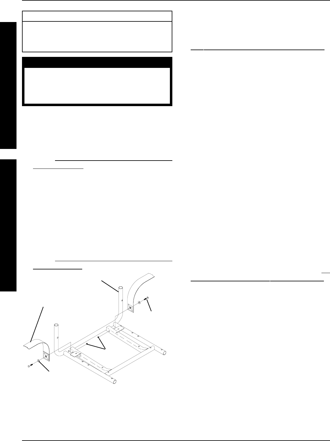
REPLACING CAPTAINS VAN SEAT
ARMREST PLATE (FIGURE 2)
1. If necessary, remove the three (3) mounting screws,
spacers and locknuts that secure the joystick mount-
ing bracket to the armrest plate.
2. Remove armrest pad. Refer to REPLACING ARM-
REST PADS - CAPTAINS VAN SEATS in this proce-
dure of the manual.
3. Remove the mounting screw, washers and locknut that
secure the existing armrest plate to the arm weldment.
4. Position the NEW armrest plate on the armrest weldment
and secure with the mounting screw, washers, and lock-
nut. Refer to FIGURE 2 for correct hardware orientation.
5. Reinstall van style armrest pad. Refer to REPLAC-
ING ARMREST PADS - CAPTAINS VAN SEATS in
this procedure of the manual.
6. If necessary, reinstall the three (3) mounting screws,
spacers and locknuts that secure the joystick mount-
ing bracket to the armrest plate.
7. Repeat STEPS 1-6 for the opposite armrest plate, if
necessary.
Mounting
Screw
Washer Locknut
Washer
FIGURE 2 - REPLACING CAPTAINS VAN SEAT
ARMREST PLATE
Arm Weldment
Armrest
Plate
FRONTREAR
This Procedure Includes the Following:
Replacing Armrest Pads - Captains Van Seats
Replacing Captains Van Seat Armrest Plate
WARNING
After ANY adjustments, repair or service
and BEFORE use, make sure that all attach-
ing hardware is tightened securely - oth-
erwise injury or damage may result.
20
UPHOLSTERY/POSITIONING STRAPPROCEDURE 5
U
P
H
O
L
S
T
E
R
Y
P
O
S
I
T
I
O
N
I
N
G
S
T
R
A
P
This Procedure Includes the Following:
Replacing Seat Positioning Strap - Captains Van
Seats
Replacing Back Upholstery
WARNING
After ANY adjustments, repair or service and BE-
FORE use, make sure that all attaching hardware
is tightened securely - otherwise injury or damage
may result.
FIGURE 1 - REPLACING SEAT POSITIONING STRAP -
CAPTAINS VAN SEATS
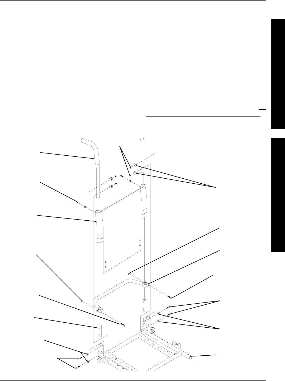
REPLACING BACK UPHOLSTERY
(FIGURE 2)
1. Remove one (1) armrest from the wheelchair. Refer to
INSTALLING/REMOVING FLIP BACK ARMRESTS in
PROCEDURE 4 of the owners manual, 1081227.
2. If applicable, remove the two (2) mounting screws
and locknuts that secure the spreader bar to the back
canes.
3. Remove the two (2) mounting screws and washers
that secure the existing back upholstery to the back
canes.
4. Cut the tie-wraps that secure the bottom of the exist-
ing back upholstery to the back canes.
NOTE: Note the back angle before disassembly for proper
reinstallation.
5. On the side of the wheelchair that the armrest was
removed, remove one (1) of the mounting screws,
washer, spacer, and locknut that secures the back
cane to the seat frame.
NOTE: To avoid losing the insert in each back cane, thread
the mounting screw just removed through the cane from
the inside of the wheelchair to hold the insert in place.
6. Remove the other mounting screw, washer, spacer,
and locknut that secures the back cane to the seat
frame.
7. Slide the back cane out of the spreader bar (If appli-
cable) and the existing back upholstery.
8. Remove other armrest from the chair. Refer to IN-
STALLING/REMOVING FLIP BACK ARMRESTS in
PROCEDURE 4 of the owners manual, 1081227.
9. Repeat STEPS 5-7 for the opposite side of the wheel-
chair.
10. Slide the other back cane out of the spreader bar (if
applicable) and the existing back upholstery.
11. Slide one(1) back cane into NEW back upholstery
and through spreader bar (if applicable).
12. Secure back cane to the seat frame from the outside
of the wheelchair with the existing two (2) mounting
screws, washers, spacers, and locknuts. Use Loctite
242 and torque to 75-in/lbs.
13. Repeat STEPS 11-12 for opposite back cane.
14. Secure the top of the NEW back upholstery to the
back canes with the two (2) existing mounting screws.
Van Seat Frame
Seat Positioning
Strap
Locknuts
Washer FRONT OF SEAT
FRAME
REAR OF SEAT
FRAME Mounting
Screw
REPLACING SEAT POSITIONING
STRAP - CAPTAINS VAN SEATS
(FIGURE 1)
1. Remove the van style seat from the van seat frame.
Refer to INSTALLING/REMOVING CAPTAINS VAN
SEAT ASSEMBLY in PROCEDURE 6 of this manual.
2. Remove the two (2) rear mounting screws, washers,
and locknuts that secure the seat positioning straps
to the van seat frame.
NOTE: The washer is positioned between the seat posi-
tioning strap and the mounting screw.
3. Secure the NEW seat positioning strap halves with
the mounting screws, washers and locknuts to the
van seat frame and torque to 75-inch pounds.
4. Reinstall the van style seat to the van seat frame.
Refer to INSTALLING/REMOVING CAPTAINS VAN
SEAT ASSEMBLY in PROCEDURE 6 of this manual.
21
FIGURE 2 - REPLACING BACK UPHOLSTERY
Locknut
(STEP 2)
Mounting
Screw
(STEP 2)
Locknut
(STEP 2)
Mounting Screw
Torque to 60 in/lbs
(STEP 2)
Spreader Bar
(STEPS 2, 7, 16)
Mounting
Screw
(STEPS 3, 14)
Washer
(STEPS 3, 14)
Back
Upholstery
(STEPS 3, 7)
Back Cane
(STEPS 3, 12)
Insert
Seat Frame
Mounting Screws
Torque to 75 in/lbs
(STEPS 5, 6)
Washers
(STEPS 5, 6)
Mounting
Screws
(STEPS 5, 6)
Washers
(STEPS 5, 6)
Spacers
(STEPS 5, 6)
Locknuts
(STEPS 5, 6)
HEAVY DUTY MODELS
NOTE: Spreader bar required on all back heights.
BACK HEIGHT u SPREADER BAR
HEIGHT
16-17-inches 5-inches
18-24-inches 7-inches
uHeight of Spreader Bar from Bottom of Back
Canes to Top of Spreader Bar Clamp.
15. If applicable, reposition the spreader bar at the correct
height for the corresponding back height and torque
the mounting hardware to 60-in/lbs.
16. Reinstall the armrest onto the wheelchair. Refer to IN-
STALLING/REMOVING FLIP BACK ARMRESTS in
PROCEDURE 4 of the owners manual, 1081227.
NOTE: When replacing the back upholstery, back as-
sembly or changing back height, follow these guidelines
for spreader bar height:
STANDARD MODELS
BACK HEIGHT u SPREADER BAR
HEIGHT
16-inches* 5-inches
17-inches* 5-inches
18-19-inches* 7-inches
20-24-inches 7-inches
NOTE: Spreader Bar required on ALL back heights be-
tween 20-24-inches. *Spreader bar required on back
heights 16,17,18, or 19 ONLY if the width or depth of the
chair exceeds 19-inches.
uHeight of Spreader Bar from Bottom of Back
Canes to Top of Spreader Bar Clamp.
UPHOLSTERY/POSITIONING STRAP PROCEDURE 5
U
P
H
O
L
S
T
E
R
Y
P
O
S
I
T
I
O
N
I
N
G
S
T
R
A
P
22
PROCEDURE 6 SEAT FRAME
S
E
A
T
F
R
A
M
E
This Procedure includes the following:
Preparation for Removing/Installing Seat Frame
(Standard Frame, Adjustable Frame,
and Captains Van Seat) ............................Page 21
Replacing Exact Same Size Standard
Seat Frame .............................................. Page 22
Removing/Installing Standard Seat Frame
Sub-Assembly .........................................Page 22
Changing Seat Depth ............................... Page 23
Changing Seat Width (Standard and Adjustable
Seat Frame) .............................................Page 25
Installing/Removing Adjustable Seat Frame
Sub-Assembly and/or Component
Replacement ...........................................Page 26
Installing/Removing Captains Van Seat
Assembly ................................................Page 28
Replacing Captains Van Seat and/or Captains
Van Seat Frame ....................................... Page 28
Converting From Standard Seat Frame to
Adjustable Seat Frame or Vice Versa .......Page 29
Converting From Adjustable Seat Frame to
Captains Van Seat or Vice Versa ............... Page 29
Converting From Standard Seat Frame to
Captains Van Seat or Vice Versa ............... Page 30
Removing/Installing Seat Pan .................. Page 30
Mounting Plate - Seat Angle Adjustment and
Installation Orientation .............................Page 31
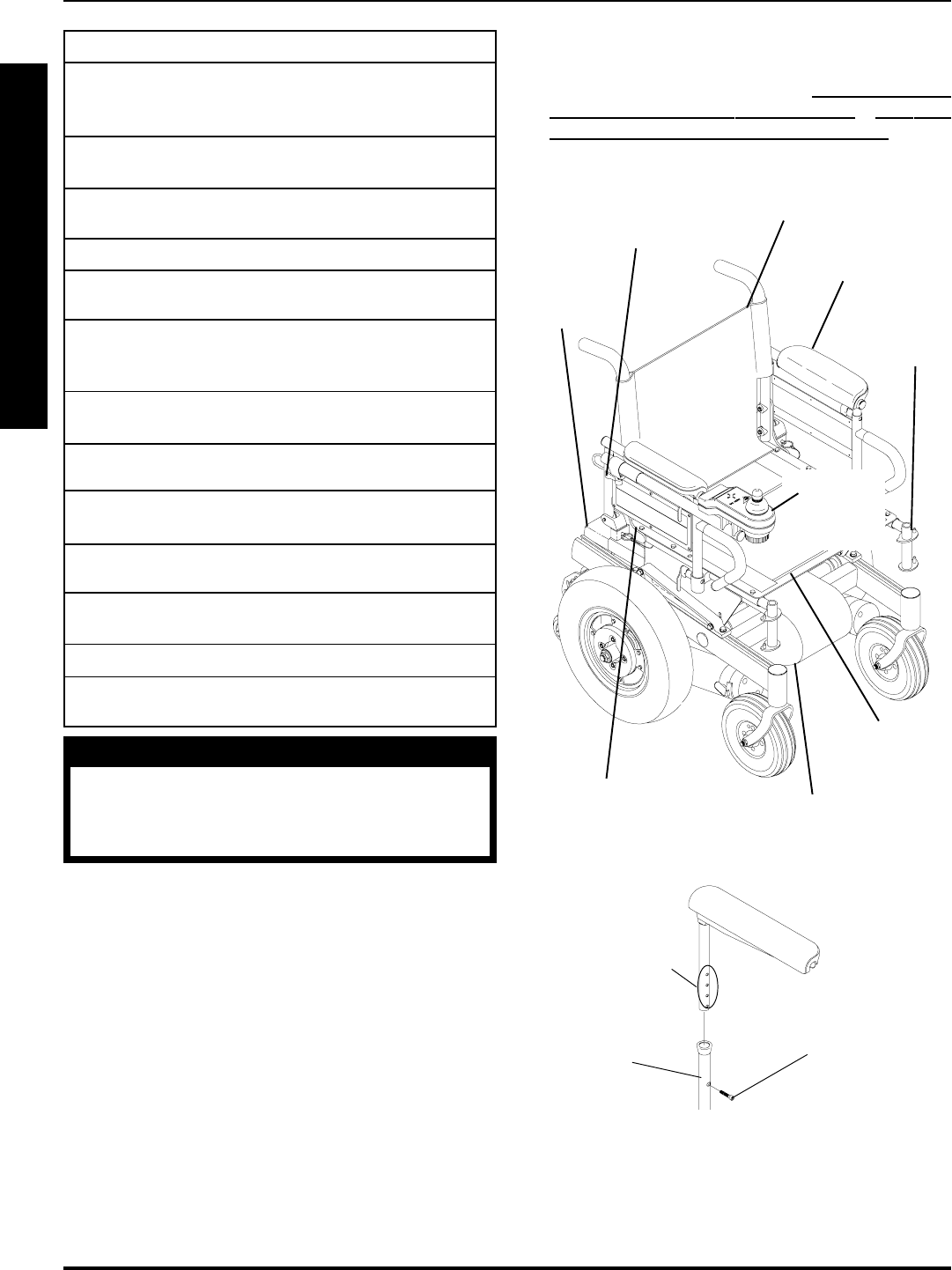
PREPARATIONS FOR REMOVING/
INSTALLING SEAT FRAME
(STANDARD FRAME, ADJUSTABLE
FRAME, AND CAPTAINS VAN SEAT)
(FIGURE 1)
NOTE: When installing/replacing components of the wheel-
chair, refer to the individual procedure for correct use of
LOCTITE 242 and torque specifications or PROCEDURE
3 of this manual.
NOTE: To reinstall these components, reverse the follow-
ing steps.
FIGURE 1 - PREPARATIONS FOR REMOVING/
INSTALLING SEAT FRAME (STANDARD FRAME,
ADJUSTABLE FRAME, AND CAPTAINS VAN SEAT)
Footrest
Location
(STEP 1)
Battery
Box(es)
(STEP 2)
Adjustment Lock
Lever for Joystick
(STEP 4)
Joystick
(STEPS
3,5)
Flip Back
Armrests
(STEP 6A)
Seat Pan
(STEP 7)
Controller, Left/Right Motor
Connectors (STEPS 8,9)
Back Upholstery
(STEP 10)
Seat Positioning
Strap (STEP 7)
NOTE: Illustration depicts tubular seat frame only. Prepa-
ration steps for the captains van seat apply in the same
manner.
Socket
Screw
Captains
Van Seat
Base
Height
Adjustment
Holes
STEP 6B
1. Remove footrest assemblies. Refer to PROCEDURE
4 in of the owners manual, 1081227.
2. Remove battery box(es). Refer to INSTALLING/RE-
MOVING GROUP 24 BATTERY BOXES or INSTALL-
ING/REMOVING GROUP 22 BATTERY BOX in PRO-
CEDURE 9 of this manual.
WARNING
After ANY adjustments, repair or service
and BEFORE use, make sure that all at-
taching hardware is tightened securely -
otherwise injury or damage may result.
NOTE: The procedures in this section of the manual refer
to NON-RECLINER seat frames only, EXCEPT Seat
Angle Adjustment. For recliner seat frames, refer to PRO-
CEDURE 14 of this manual.
23
3. Cut tie wraps and disconnect joystick from controller.
4. Turn the lever on the adjustment lock to release the
adjustment lock from the joystick mounting tube.
5. Remove the joystick from the wheelchair.
6. Perform one (1) of the following:
A. STANDARD OR ADJUSTABLE SEAT
FRAMES - Remove the flip-back armrests from
the wheelchair. Refer to INSTALLING/REMOVING
FLIP BACK ARMRESTS in PROCEDURE 4 of
the owners manual, 1081227.
B. CAPTAINS VAN SEAT - Remove the mounting
screw that secures the armrest to the van seat
frame. Repeat for opposite side.
7. For standard and adjustable seat frames, remove the
seat pan (including seat positioning straps). Refer to
REMOVING/INSTALLING SEAT PAN in this procedure
of the manual.
8. Disconnect battery and left/right motor connectors from
the controller. Refer to REPLACING WIRING HAR-
NESS in PROCEDURE 10 of this manual.
9. Remove tie-wraps that secures the wiring harness to
the seat frame and the charger cable from its mount-
ing bracket. Refer to REPLACING WIRING HARNESS
in PROCEDURE 10 of this manual.
10. For standard and adjustable seat frames, remove the
back upholstery (including back canes and spreader
bar, if applicable). Refer to REPLACING BACK UP-
HOLSTERY in PROCEDURE 5 of the manual.
11. Refer back to the starting procedure to complete the
desired change.
REPLACING EXACT SAME SIZE
STANDARD SEAT FRAME
1. Perform the instructions outlined in PREPARATIONS
FOR REMOVING/INSTALLING SEAT FRAME (STAN-
DARD FRAME, ADJUSTABLE FRAME, AND CAP-
TAINS VAN SEAT) in this procedure of the manual.
2. Remove the existing standard seat frame subassem-
bly and install the NEW standard frame. Refer to RE-
MOVING/INSTALLING STANDARD SEAT FRAME
SUBASSEMBLY in this procedure of the manual.
3. FOR 12-15-INCH SEAT DEPTHS ONLY: Remove
the CJ back brackets from the existing standard seat
frame and install onto the NEW standard seat frame.
Refer to REMOVING/INSTALLING CJ BACK BRACK-
ETS FROM SEAT FRAME in this procedure of the
manual.
4. Reinstall the components previously removed in STEP
1. Perform the instructions outlined in PREPARATIONS
FOR REMOVING/INSTALLING SEAT FRAME (STAN-
DARD FRAME, ADJUSTABLE FRAME, AND CAP-
TAINS VAN SEAT) in this procedure of the manual.
REMOVING/INSTALLING
STANDARD SEAT FRAME
SUBASSEMBLY (FIGURE 2)
NOTE: Perform steps required from starting procedure.
Removing
1. Remove the four (4) mounting screws, locknuts and
spacers, if applicable, that secure the standard seat
frame subassembly to the seat mounting plates.
2. Remove the existing standard seat frame.
FIGURE 2 - REMOVING/INSTALLING STANDARD
SEAT FRAME SUB-ASSEMBLY
Mounting Screws
(Torque to 156-
inch pounds)
Standard
Seat
Assembly
Locknuts Base Frame
Spacer
(16-inch
Wide Only)
Seat
Mounting
Plate
Spacer
(16-inch Wide
Only)
Mounting Screws
(Torque to 156-
inch pounds)
NOTE: For 16-inch wide seat frames, there will be spac-
ers positioned between the seat frame and the seat mount-
ing plates.
S
E
A
T
F
R
A
M
E
PROCEDURE 6SEAT FRAME

24
3. Refer back to the starting procedure to complete the
desired change.
Installing
1. Position NEW standard seat frame subassembly on
seat mount plates.
2. Secure NEW standard seat frame subassembly onto
seat mounting plates with the existing four (4) mount-
ing screws, locknuts and spacers, if applicable. Torque
to 156-inch pounds.
3. Refer back to the starting procedure to complete the
desired change.
CHANGING SEAT DEPTH
Standard Seat Frame
NOTE: Review the chart below. This will determine the
components needed to obtain the desired seat depth.
B. If the desired change only requires a NEW seat
pan, refer to
REMOVING/INSTALLING SEAT PAN
in this procedure of the manual.
C. For all other seat depth changes, perform the fol-
lowing:
lPREPARATIONS FOR REMOVING/IN-
STALLING SEAT FRAME (STANDARD
FRAME, ADJUSTABLE FRAME, AND CAP-
TAINS VAN SEAT) in this procedure of the
manual.
Perform one (1), two (2), or all three (3) of the pro-
cedures listed below depending on the compo-
nents required for the desired seat depth deter-
mined from STEPS 1-5:
lREMOVING/INSTALLING CJ BACK BRACK-
ETS in this procedure of the manual.
lREMOVING/INSTALLING STANDARD SEAT
SUBASSEMBLY in this procedure of the
manual.
lREMOVING/INSTALLING SEAT PAN in this
procedure of the manual.
After completing the procedure(s) listed above, per-
form the steps outlined in PREPARATIONS FOR
REMOVING/INSTALLING SEAT FRAME (STAN-
DARD FRAME, ADJUSTABLE FRAME, AND
CAPTAINS VAN SEAT) to complete the desired
seat depth change.
Adjustable Seat Frame (FIGURE 3)
NOTE: Review the chart below. This will determine the com-
ponents needed to obtain your desired seat depth.
SEAT FRAME COMPONENTS
CJ BACK SEAT
SEAT BRACKETS SEAT FRAME
DEPTH REQUIRED PAN DEPTH
12-inches
to YES 17-inch 16-inch deep
15-inches
16-inches NO 16-inch 16-inch deep
17-inches NO 17-inch 16-inch deep
18-inches NO 18-inch 18-inch deep
19-inches NO 19-inch 18-inch deep
20-inches NO 20-inch 20-inch deep
21-inches NO 21-inch 20-inch deep
22-inches NO 22-inch 22-inch deep
COMPONENT IDENTIFICATION TABLE
FOR STANDARD SEAT FRAME
1. Find current seat depth in left hand column in the chart.
2. Follow that row to right under seat frame components.
3. Verify and note the components of the current seat depth.
4. Repeat STEPS 1-3 for your desired seat depth.
5. Compare existing components of the current seat depth
and the required components for the desired seat depth.
6. Perform one (1) of the following:
A. If the current seat depth and the desired seat depth
is within the 12-15-inch seat depth range, this change
can be accomplished by repositioning the back
canes on the CJ back brackets. Refer to CHANG-
ING SEAT DEPTH BETWEEN 12-15-INCHES in
this procedure of the manual.
NOTE: Note the four (4) different lengths of side frames
short, medium, long, and X-long, as well as the two differ-
ent center frames, short and long. These components are
interchanged to obtain the various different seat depths.
SEAT FRAME COMPONENTS
CJ BACK
SEAT BRACKETS SEAT SIDE CENTER
DEPTH REQUIRED PAN FRAME FRAME
12-inches
to YES 17-inch Short Short
15-inches
16-inches NO 16-inch Short Short
17-inches NO 17-inch Short Short
18-inches NO 18-inch Medium Short
19-inches NO 19-inch Medium Short
20-inches NO 20-inch Long Long
21-inches NO 21-inch Long Long
22-inches NO 22-inch X-Long Long
COMPONENT IDENTIFICATION TABLE
FOR STANDARD SEAT FRAME
PROCEDURE 6 SEAT FRAME
S
E
A
T
F
R
A
M
E
25
1. Find current seat depth in left hand column in the chart.
2. Follow that row to right under seat frame components.
3. Verify and note the components of the current seat depth.
4. Repeat STEPS 1-3 for the desired seat depth.
5. Compare existing components of the current seat depth
and the required components for the desired seat depth.
To adjust the depth of the seat on the wheelchair, use
the following guidelines:
If the current seat depth is and the desired seat depth are
within the 12-15-inch seat depth range, this change can be
accomplished by repositioning the back canes on the CJ
back brackets. Refer to CHANGING SEAT DEPTH BE-
TWEEN 12-15-INCHES in this procedure of the manual.
If the desired change only requires a NEW seat pan, refer to
REMOVING/INSTALLING SEAT PAN in this procedure of
the manual.
If the desired change requires the removal/installation of CJ
back brackets, refer to REMOVING/INSTALLING CJ BACK
BRACKETS in PROCEDURE 8 of this manual.
If the desired change requires a new side frame, and/or new
center frame, perform the following steps:
A. Perform the instructions outlined in SEAT FRAME
REMOVING/INSTALLING PREPARATIONS FOR
STANDARD FRAME, ADJUSTABLE FRAME, AND
CAPTAINS VAN SEAT in this procedure of the
manual.
NOTE: Note the mounting hole position of the side
frame for proper installation of the NEW side frame.
B. Remove the two (2) mounting screws, coved wash-
ers, spacers, and locknuts that secure the side frame
to the center frame.
C. Remove the side frame from the center frame.
D. Repeat STEPS A and B for opposite side frame.
If the desired seat depth requires a new center
frame, determined in STEPS 1-5 perform STEPS
E - G, otherwise proceed to STEP H.
E. Remove the four (4) mounting screws that secure
the EXISTING center frame to support brackets.
F. Remove existing center frame from seat mount
plates.
G. Secure NEW center frame to support brackets with
the existing four (4) mounting screws and locknuts.
Torque to 156-inch pounds.
H. Secure NEW side frame to the center frame at the
position noted previously. Torque to 75-inch pounds.
NOTE: If seat width adjustment is also desired, re-
fer to CHANGING SEAT WIDTH in this procedure
of the manual for mounting hole locations and allow-
able seat width/seat depth combinations.
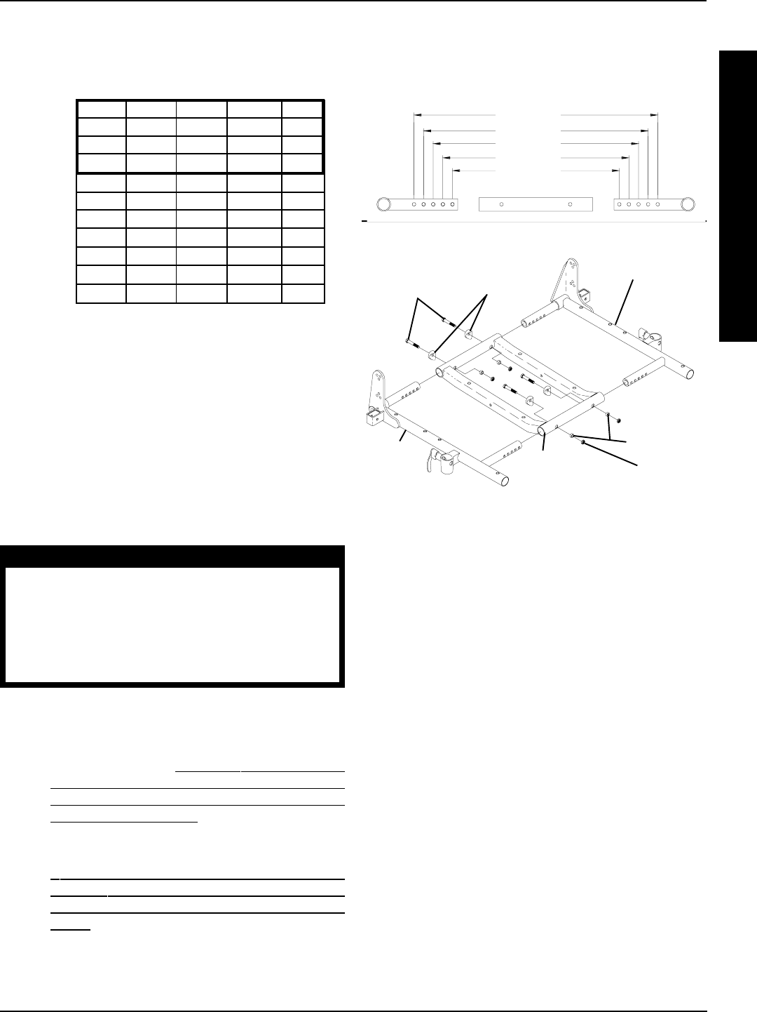
FIGURE 3- CHANGING SEAT DEPTH - ADJUSTABLE
SEAT FRAME
Side Frame
Side
Frame
Center
Frame
Mounting
Screws
(Torque to 75-
inch pounds)
Coved
Washers
Spacers
Locknuts
Mounting Screws
(Torque to 156-
inch pounds)
Support Brackets
Changing Seat Depth Between 12 and 15-
Inches (FIGURE 4)
NOTE: There are two (2) sizes of CJ back brackets. Refer
to the following chart to determine if the seat depth required
is obtainable by repositioning the back canes only, or if the
CJ back brackets must be replaced.
CJ BACK BRACKET (SEAT DEPTH) RANGES
12 and 13-inches OR 14 and 15-inches
If seat depth required is within seat depth range of
the original CJ back brackets, only the back canes
need to be repositioned. Refer to the following pro-
cedure.
If the seat depth required is NOT within the seat depth
range of the original CJ back brackets, the CJ back
brackets must be replaced before repositioning the
back canes. Refer to REMOVING/INSTALLING CJ
BACK BRACKETS in PROCEDURE 8 of this manual.
S
E
A
T
F
R
A
M
E
PROCEDURE 6SEAT FRAME

26
FIGURE 4 - ADJUSTING SEAT DEPTH - CHANGING
SEAT DEPTH BETWEEN 12 AND 15-INCHES
CJ Back
Bracket
Seat
Frame
Threaded
Insert
Washers
Back Cane
Coved
Washers
Mounting Screws (Torque to 75-inch pounds)
1. Remove the armrests from the wheelchair. Refer to IN-
STALLING/REMOVING FLIP BACK ARMRESTS in
PROCEDURE 4 of the owners manual, 1081227.
2. Cut the tie wraps that secure the back upholstery to the
CJ back brackets.
3. Pull the bottom of the back upholstery away from the
rear of the seat pan.
4. Remove mounting screw, washer and coved washer
from the top mounting hole of the CJ back bracket and
back cane.
NOTE: Before removing the back canes from the CJ back
brackets, note the BACK ANGLE for reinstallation.
NOTE: To avoid losing the insert in each back cane, line up
the holes in the insert with the holes in the back cane and
start one of the screws through the cane from the inside of
the wheelchair to hold the insert in place.
5. Remove the mounting screw, washer and coved
washer from the bottom mounting hole of the CJ back
bracket and the back cane.
6. Reposition the back cane to the desired seat depth
and angle. If changing the back angle as well, refer to
BACK ANGLE ADJUSTMENT in PROCEDURE 8 of
this manual.
7. Secure bottom of the back upholstery to the seat pan.
8. Secure the bottom of the back upholstery to the CJ
back brackets with new tie wraps.
9. Use Loctite 242 and torque the mounting screws to
75-inch pounds.
10. Repeat the STEPS 1-9 for the opposite back cane.
11. Reinstall the armrests onto the wheelchair. Refer to IN-
STALLING/REMOVING FLIP BACK ARMRESTS in
PROCEDURE 4 of the owners manual, 1081227.
CHANGING SEAT WIDTH
(STANDARD AND ADJUSTABLE
SEAT FRAME)
Standard Seat Frame
NOTE: If changing seat width below 16-inches wide, you must
convert to an adjustable seat frame. Refer to CONVERT-
ING FROM STANDARD TO ADJUSTABLE SEAT
FRAME OR VICE VERSA in this procedure of the manual.
For all changes above 16-inches wide, perform the outlined
steps.
1. Perform the instructions outlined in PREPARATIONS
FOR REMOVING/INSTALLING SEAT FRAME (STAN-
DARD FRAME, ADJUSTABLE FRAME, AND CAP-
TAINS VAN SEAT) in this procedure of the manual.
2. Remove the existing standard seat frame subassem-
bly and install the NEW standard frame. Refer to RE-
MOVING/INSTALLING STANDARD SEAT FRAME
SUBASSEMBLY in this procedure of the manual.
3. FOR 12-15-INCH SEAT DEPTHS ONLY: Remove
the CJ back brackets from the existing standard seat
frame and install onto the NEW standard seat frame.
Refer to REMOVING/INSTALLING CJ BACK BRACK-
ETS in PROCEDURE 8 of this manual.
4. Reinstall the components previously removed in STEP
1. Perform the instructions outlined in
PREPARATIONS
FOR REMOVING/INSTALLING SEAT FRAME (STAN-
DARD FRAME, ADJUSTABLE FRAME, AND CAP-
TAINS VAN SEAT) in this procedure of the manual.
Adjustable Seat Frame (FIGURE 5)
NOTE: If changing seat width above 16-inches wide, you
must convert to a standard seat frame. Refer to CONVERT-
ING FROM STANDARD TO ADJUSTABLE SEAT
FRAME OR VICE VERSA in this procedure of the manual.
For all changes below 16-inches wide, perform the outlined
steps.
1. Perform the instructions outlined in PREPARATIONS
FOR REMOVING/INSTALLING SEAT FRAME (STAN-
DARD FRAME, ADJUSTABLE FRAME, AND CAP-
TAINS VAN SEAT) in this procedure of the manual.
2. Review the following chart for the allowable seat width
and seat depth combinations for the adjustable seat
frame.
PROCEDURE 6 SEAT FRAME
S
E
A
T
F
R
A
M
E
27
ALLOWABLE SEAT WIDTH AND DEPTH
COMBINATIONS FOR ADJUSTABLE SEAT FRAME
NOTE: The seat widths and seat depths enclosed in the
outlined box will require the use of CJ back brackets and a
17-inch deep seat pan.
3. Remove the two (2) mounting screws, coved washers,
spacers, and locknuts that secure the side frame to the
center frame.
4. Adjust side frame to desired width determined from
STEP 2. See DETAIL A for proper mounting hole
position.
5. Secure side frame to center frame with existing mount-
ing screws, coved washers, spacers, and locknuts.
Torque mounting screws to 75-inch pounds.
WARNING
Both side frames MUST be adjusted to the
same mounting hole position to maintain
proper weight balance of user and seat
frame. If weight is not balanced, injury to
the assistant and/or user and damage to
the wheelchair may result.
6. Repeat STEPS 3-5 for opposite side frame.
7. Perform one (1) of the following:
A. For adjusting the seat width only, perform the in-
structions outlined in PREPARATIONS FOR RE-
MOVING/INSTALLING SEAT FRAME (STAN-
DARD FRAME, ADJUSTABLE FRAME, AND
CAPTAINS VAN SEAT) in this procedure of the
manual.
NOTE: When performing the steps outlined in
PREPARATIONS FOR REMOVING/INSTALL-
ING SEAT FRAME (STANDARD FRAME, AD-
JUSTABLE FRAME, AND CAPTAINS VAN
SEAT) the seat pan, seat cushion, back uphol-
stery and spreader bar (if applicable), will need to
be replaced. Spreader bars are only required on
seat depths greater than 19-inches.
FIGURE 5 -CHANGING SEAT WIDTH - ADJUSTABLE
SEAT FRAME
Side
Frame
STEPS 3-6
Side Frame
Center
Frame
Mounting
Screws
Coved
Washers
Spacers
Locknut
INSTALLING/REMOVING
ADJUSTABLE SEAT FRAME
SUBASSEMBLY AND/OR
COMPONENT REPLACEMENT
(FIGURE 6)
Converting from Adjustable Seat Frame to
Standard Seat Frame or Captains Van Seat
NOTE: This section must be performed in conjunction with
a starting procedure.
1. Remove the four (4) mounting screws that secure the
two (2) support brackets of the adjustable seat frame
subassembly to the seat mounting plates.
2. To complete conversion, refer back to the starting pro-
cedure to complete the desired change.
Converting from Standard Seat Frame or
Captains Van Seat To Adjustable Seat Frame
NOTE: This section must be performed in conjunction with
a starting procedure.
NOTE: When converting the seat frame, you will need a
seat pan, seat cushion, back upholstery and spreader bar (if
applicable). Spreader bars are only required on seat depths
of greater than 19-inches.
S
E
A
T
F
R
A
M
E
PROCEDURE 6SEAT FRAME
12 13 14 15 16
12 ✓✓✓✓✓
13 ✓✓✓✓✓
14 ✓✓✓✓✓
15 ✓✓✓✓✓
16 ✓✓✓✓✓
17 N/A N/A ✓✓✓
18 N/A N/A ✓✓✓
19 N/A N/A ✓✓✓
20 N/A N/A ✓✓✓
21 N/A N/A ✓✓✓
22 N/A N/A ✓✓✓
S
E
A
T
D
E
P
T
H
SEAT WIDTH
B. For all other changes regarding seat frame changes,
refer back to the starting procedure to complete the
desired change.
DETAIL “A”
12-inches
13-inches
14-inches
15-inches
16-inches

28
FIGURE 6 - INSTALLING/REMOVING ADJUSTABLE SEAT FRAME SUBASSEMBLY AND/OR COMPONENT
REPLACEMENT
Mounting Screws
(Torque to 156-inch pounds)
Side Frame
Side Frame
Center Frame
Spacer
Locknuts
Support
Bracket
Base
Frame
Coved Washer
Locknuts
Locknuts
Support
Bracket
Mounting Screws
(Torque to 156-inch
pounds)
Mounting Screws
(Torque to 156-inch
pounds)
Mounting
Plate
Mounting Screws
(Torque to 75-inch
pounds)
1. Secure both support brackets to the seat mounting plates
with four (4) mounting screws and locknuts as shown in
FIGURE 6. Torque mounting screws to 156-inch pounds.
2. Secure the center frame to the support brackets with
four (4) mounting screws, locknuts, and spacers. Torque
to 156-inch pounds.
3. Insert the side frame into the center frame and secure
with mounting screw, coved spacer, spacer, and lock-
nut. Torque to 75-inch pounds. Repeat for opposite side
frame.
4. To complete conversion, refer back to the starting proce-
dure to complete the desired change.
Component Replacement
1. Perform the instructions outlined in PREPARATIONS
FOR REMOVING/INSTALLING SEAT FRAME (STAN-
DARD FRAME, ADJUSTABLE FRAME, AND CAP-
TAINS VAN SEAT) in this procedure of the manual.
NOTE: Note the mounting hole position of the current side
frame(s) for proper installation of the NEW side frame(s).
2. Remove the two (2) mounting screws, coved spacers,
spacers, and locknuts that secure the side frame to the
center frame.
Mounting Screws
(Torque to 156-inch pounds)
PROCEDURE 6 SEAT FRAME
S
E
A
T
F
R
A
M
E
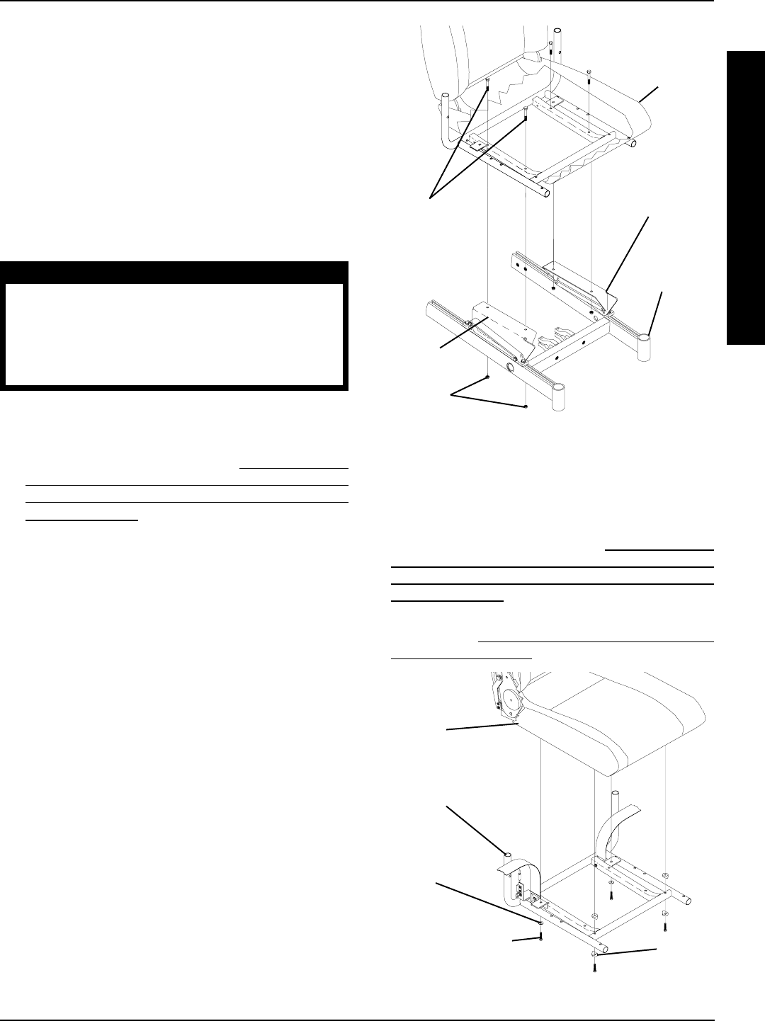
29
3. Perform one (1) of the following:
A. If center frame needs replaced, repeat STEP 2 for
opposite side frame and proceed to STEP 4.
B. If opposite side frame needs replaced, repeat STEP
2, then proceed to STEP 6. Otherwise proceed to
STEP 6.
4. Remove the four (4) mounting screws and locknuts that
secure the center frame to the support brackets.
5. Secure NEW center frame to support brackets with ex-
isting four (4) mounting screws and locknuts. Torque to
156-inch pounds.
WARNING
Both side frames MUST be adjusted to the
same mounting hole position to maintain
proper weight balance of user and seat
frame. If weight is not balanced, injury to
the assistant and/or user and damage to
the wheelchair may result.
6. Install new/existing side frame(s) into new/existing cen-
ter frame at the mounting position previously noted. Torque
to 75-inch pounds.
7. Perform the instructions outlined in PREPARATIONS
FOR REMOVING/INSTALLING SEAT FRAME (STAN-
DARD FRAME, ADJUSTABLE FRAME, AND CAP-
TAINS VAN SEAT) in this procedure of the manual.
INSTALLING/REMOVING CAPTAINS
VAN SEAT ASSEMBLY (FIGURE 7)
NOTE: This procedure is to be performed in conjunction with
a starting procedure. Proceed to the section that reflects the
desired change.
Installing Captains Van Seat
1. Position the captains van seat on the seat mounting plates
at the position shown in FIGURE 7.
2. Line up mounting holes in the captains van seat frame
and the mounting holes in the seat mounting plates.
3. Secure the captains van seat to the seat mounting plates
with four (4) mounting screws, and locknuts. Torque to
156-inch pounds.
4. Refer back to the starting procedure to complete the
desired change.
Removing Captains Van Seat
1. Remove the four (4) mounting screws and locknuts that
secure the captains van seat to the seat mounting plates.
2. Remove captains van seat from seat mounting plates.
3. Refer back to the starting procedure to complete the
desired change.
FIGURE 7 - REMOVING/INSTALLING CAPTAINS VAN
SEAT ASSEMBLY
Mounting
Screws
(Torque to 156-
inch pounds)
Locknuts
Seat
Mounting
Plate
Base Frame
Seat Mounting
Plate
Captains Van
Seat
REPLACING CAPTAINS VAN SEAT
AND/OR CAPTAINS VAN SEAT
FRAME (FIGURE 8)
1. Perform the instructions outlined in PREPARATIONS
FOR REMOVING/INSTALLING SEAT FRAME (STAN-
DARD FRAME, ADJUSTABLE FRAME, AND CAP-
TAINS VAN SEAT) in this procedure of the manual.
2. Remove the captains van seat assembly from the wheel-
chair. Refer to INSTALLING /REMOVING CAPTAINS
VAN SEAT ASSEMBLY in this procedure of the manual.
Mounting Screw
(Torque to 75-inch
pounds)
FIGURE 8 - REPLACING CAPTAINS VAN SEAT AND/
OR CAPTAINS VAN SEAT FRAME
Captains
Van Seat
Frame
Captains
Van Seat
Washer
Spacer
S
E
A
T
F
R
A
M
E
PROCEDURE 6SEAT FRAME

30
6. Perform the instructions outlined in PREPARATIONS
FOR REMOVING/INSTALLING SEAT FRAME (STAN-
DARD FRAME, ADJUSTABLE FRAME, AND CAP-
TAINS VAN SEAT) in this procedure of the manual.
CONVERTING FROM ADJUSTABLE
SEAT FRAME TO CAPTAINS VAN
SEAT OR VICE VERSA
1. Perform the instructions outlined in PREPARATIONS
FOR REMOVING/INSTALLING SEAT FRAME (STAN-
DARD FRAME, ADJUSTABLE FRAME, AND CAP-
TAINS VAN SEAT) in this procedure of the manual.
2. Perform one (1) of the following:
A. Remove the adjustable seat frame subassembly.
Refer to REMOVING/INSTALLING STANDARD
SEAT FRAME SUBASSEMBLY in this procedure
of the manual.
B. Remove the captains van seat Assembly. Refer to
INSTALLING/REMOVING CAPTAINS VAN SEAT
ASSEMBLY in this procedure of the manual.
3. Perform one (1) of the following sections:
Adjustable Frames
A. Install the adjustable seat frame subassembly. Re-
fer to INSTALLING/REMOVING ADJUSTABLE
SEAT FRAME SUBASSEMBLY AND/OR COM-
PONENT REPLACEMENT in this procedure of
the manual.
B. Adjust side frames to desired seat width. Refer to
CHANGING SEAT WIDTH in this procedure of the
manual for mounting hole locations and allowable
seat width/seat depth combinations.
C. 12-15-INCH SEAT DEPTHS ONLY: Install the CJ
back brackets, seat positioning strap, and quick re-
lease pin from the onto the adjustable seat frame.
Refer to REMOVING/INSTALLING CJ BACK
BRACKETS in PROCEDURE 8 of this manual.
D. Perform the instructions outlined in PREPARA-
TIONS FOR REMOVING/INSTALLING SEAT
FRAME (STANDARD FRAME, ADJUSTABLE
FRAME, AND CAPTAINS VAN SEAT) in this proce-
dure of the manual.
Captains Van Seat
A. Install the captains van seat. Refer to INSTALLING/
REMOVING CAPTAINS VAN SEAT ASSEMBLY in
this procedure of the manual.
B. Adjust the captains van seat to the desired position.
Refer to ADJUSTING CAPTAINS VAN SEAT in this
procedure of the manual.
3. Remove the four (4) mounting screws, two (2) wash-
ers, and two (2) spacers that secure the captains van
seat to the seat frame.
4. Replace the captains van seat or the seat frame.
5. Secure new/existing captains van seat to the new/exist-
ing captains van seat frame with existing four (4) mount-
ing screws and spacers. Torque to 75- inch pounds.
6. Install new captains van seat assembly onto the wheel-
chair. Refer to INSTALLING/REMOVING CAPTAINS VAN
SEAT ASSEMBLY in this procedure of the manual.
7. Perform the instructions outlined in PREPARATIONS
FOR REMOVING/INSTALLING SEAT FRAME (STAN-
DARD FRAME, ADJUSTABLE FRAME, AND CAP-
TAINS VAN SEAT) in this procedure of the manual.
CONVERTING FROM STANDARD
SEAT FRAME TO ADJUSTABLE
SEAT FRAME OR VICE VERSA
1. Perform the instructions outlined in PREPARATIONS
FOR REMOVING/INSTALLING SEAT FRAME (STAN-
DARD FRAME, ADJUSTABLE FRAME, AND CAP-
TAINS VAN SEAT) in this procedure of the manual.
2. Perform one (1) of the following:
A. Remove the existing standard seat frame subas-
sembly. Refer to REMOVING/INSTALLING STAN-
DARD SEAT FRAME SUBASSEMBLY in this pro-
cedure of the manual.
B. Remove the adjustable seat frame subassembly.
Refer to REMOVING/INSTALLING ADJUSTABLE
SEAT FRAME SUBASSEMBLY AND/OR COM-
PONENT REPLACEMENT in this procedure of the
manual.
3. Perform one (1) of the following:
A. Install the standard frame subassembly. Refer to
INSTALLING/REMOVING STANDARD SEAT
FRAME SUBASSEMBLY in this procedure of the
manual.
B. Install the adjustable seat frame subassembly. Re-
fer to INSTALLING/REMOVING ADJUSTABLE
SEAT FRAME SUBASSEMBLY AND/OR COM-
PONENT REPLACEMENT in this procedure of
the manual.
4. ADJUSTABLE FRAMES ONLY: Adjust side frame to
desired seat width. Refer to CHANGING SEAT WIDTH
in this procedure of the manual for mounting hole loca-
tions and allowable seat width/seat depth combinations.
5. STANDARD AND ADJUSTABLE FRAME WITH 12-
15-INCH SEAT DEPTHS ONLY: Remove the CJ back
brackets from the existing standard seat frame and in-
stall onto the NEW standard seat frame. Refer to RE-
MOVING/INSTALLING CJ BACK BRACKETS in PRO-
CEDURE 8 of this manual.
PROCEDURE 6 SEAT FRAME
S
E
A
T
F
R
A
M
E
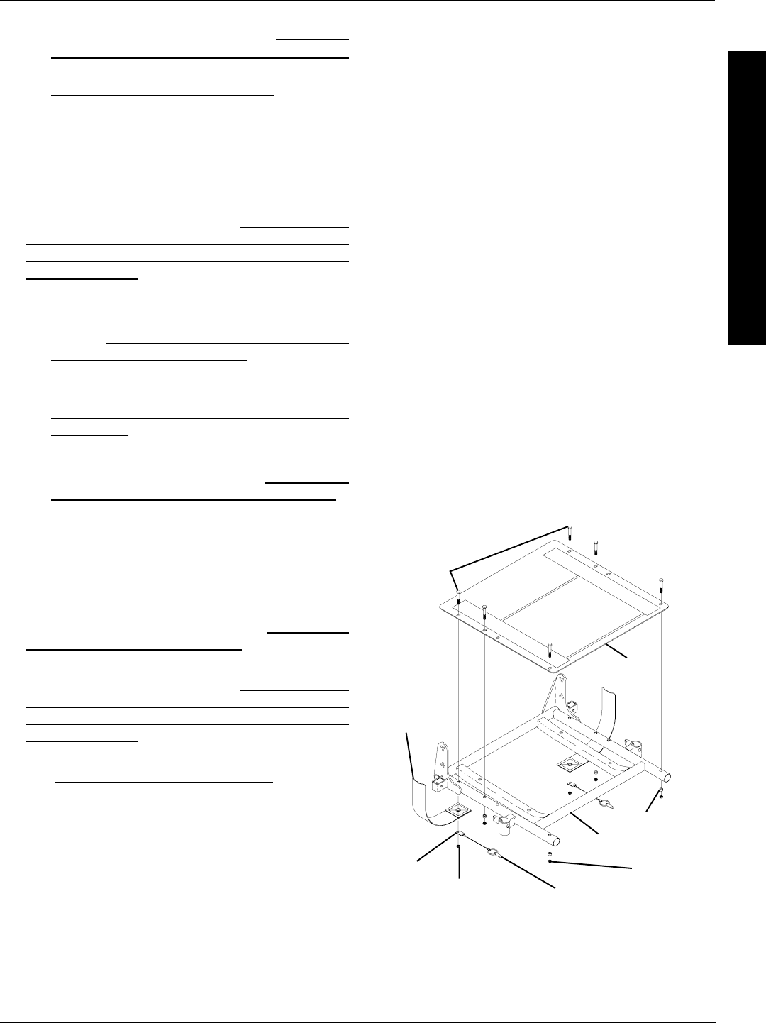
31
3. Remove the six (6) mounting screws, locknuts, and spac-
ers that secure the seat pan, seat positioning strap, and
quick release pin to the seat frame.
NOTE: When removing seat pan, note tab position of quick
release pin to the seat positioning strap.
Installing
1. Position the NEW seat pan on the seat frame, aligning
the mounting holes of the seat pan and the mounting
holes of the seat frame.
2. Position the seat positioning strap and quick release pin
tab onto the seat frame and secure with mounting screw
and locknut. See FIGURE 9 for proper orientation. Re-
peat for other seat positioning strap.
NOTE: Check seat positioning strap for proper length. The
width range for the four (4) seat positioning straps are: 12-16-
inches wide (Junior), 16-19-inches wide, 20-22-inches wide,
and 23-24-inches wide.
3. Reinstall the remaining mounting screws, locknuts, and
spacers. Torque all mounting screws to 75-inch pounds.
4. Remove the protective strips from new seat pan and
reinstall the seat cushion onto the seat pan.
5. Perform one (1) of the following:
A. When changing the seat width or depth, refer back
to that procedure to complete the desired change.
FIGURE 9 - REMOVING/INSTALLING SEAT PAN
Seat
Pan
Seat Frame
Seat
Positioning
Strap
Locknut Quick Release Pin
NOTE: Illustration shows standard frame only for clarity.
The seat pan removes/installs onto the adjustable seat
frame the way.
Mounting
Screws
Tab Locknut
Spacer
C. Perform the instructions outlined in PREPARA-
TIONS FOR REMOVING/INSTALLING SEAT
FRAME (STANDARD FRAME, ADJUSTABLE
FRAME, AND CAPTAINS VAN SEAT) in this proce-
dure of the manual.
CONVERTING FROM STANDARD
SEAT FRAME TO CAPTAINS VAN
SEAT OR VICE VERSA
1. Perform the instructions outlined in PREPARATIONS
FOR REMOVING/INSTALLING SEAT FRAME (STAN-
DARD FRAME, ADJUSTABLE FRAME, AND CAP-
TAINS VAN SEAT) in this procedure of the manual.
2. Perform one (1) of the following:
A. Remove the standard seat frame subassembly.
Refer to REMOVING/INSTALLING STANDARD
SEAT FRAME SUBASSEMBLY in this procedure
of the manual.
B. Remove the captains van seat Assembly. Refer to
INSTALLING/REMOVING CAPTAINS VAN SEAT
ASSEMBLY in this procedure of the manual.
3. Perform one (1) of the following:
A. Install the captains van seat. Refer to INSTALLING/
REMOVING CAPTAINS VAN SEAT ASSEMBLY in
this procedure of the manual.
B. Install the standard seat frame. Refer to REMOV-
ING/INSTALLING STANDARD SEAT FRAME SUB-
ASSEMBLY in this procedure of the manual.
4. STANDARD FRAMES ONLY ON 12-15-INCH SEAT
DEPTHS ONLY: Install the CJ back brackets from the
onto the adjustable seat frame. Refer to REMOVING/
INSTALLING CJ BACK BRACKETS in PROCEDURE
8 of this manual.
5. Perform the instructions outlined in PREPARATIONS
FOR REMOVING/INSTALLING SEAT FRAME (STAN-
DARD FRAME, ADJUSTABLE FRAME, AND CAP-
TAINS VAN SEAT) in this procedure of the manual.
6. Adjust the captains van seat to the desired position. Re-
fer to ADJUSTING CAPTAINS VAN SEAT in this proce-
dure of the manual.
REMOVING/INSTALLING SEAT PAN
(FIGURE 9)
Removing
1. Remove the seat cushion from the seat pan.
2. Remove the flip-back armrests from the wheelchair. Refer
to INSTALLING/REMOVING FLIP BACK ARMRESTS
in PROCEDURE 4 of the owners manual, 1081227.
S
E
A
T
F
R
A
M
E
PROCEDURE 6SEAT FRAME
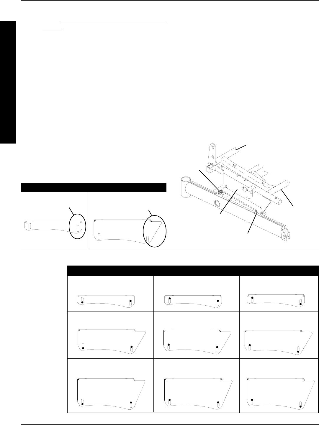
32
B. Reinstall the flip-back armrests from the wheelchair.
Refer to INSTALLING/REMOVING FLIP BACK ARM-
RESTS in PROCEDURE 4 of the owners manual,
1081227.
MOUNTING PLATE - SEAT ANGLE
ADJUSTMENT AND INSTALLATION
ORIENTATION (FIGURE 10)
Seat Angle Adjustment
NOTE: The angle of the seat is factory set providing the user
with a 5o seat dump. This angle can changed by adjusting
either the front or back of the seat mount plate to obtain any
angle between 0o or 10o seat dump.
NOTE: There are three (3) heights of seat mounting plates;
low, medium, and high. See chart below for proper settings.
1. To obtain a 0o seat dump (DETAIL A):
A. Loosen the two (2) mounting screws that secure
the rear of the seat frame to the seat mount plate.
B. Position the mounting screws at the bottom of the
rear slot.
C. Securely tighten both mounting screws. Torque to
15-in/lbs.
2. To obtain a 10o seat dump (DETAIL A):
A. Loosen the two (2) mounting screws that secure
the front of the seat frame to the seat mount plate.
B. Position the mounting screws at the bottom of the
front slot.
C. Securely tighten both mounting screws. Torque to
15-in/lbs.
Installation Orientation
1. Medium and High Seat Mounting Plates: Install with
the angled end toward the front of the wheelchair.
2. Low Seat Mounting Plates: Install with the thicker
end toward the front of the wheelchair.
Mounting Screw
Mounting
Screw
Rear of Seat Frame
Medium Height
Seat Mount Plate
Angled End of Seat
Mounting Plate
LOW MEDIUM AND HIGH
Thicker End
DETAIL A
FIGURE 10 - MOUNTING PLATE - SEAT ANGLE ADJUSTMENT AND INSTALLATION ORIENTATION
MEDIUM
HEIGHT
HIGH
HEIGHT
LOW
HEIGHT
0o5o10o
SEAT DUMP
SEAT
MOUNT
PLATE
FRONT OF
CHAIR
REAR OF
CHAIR
FRONT OF
CHAIR
REAR OF
CHAIR
FRONT OF
CHAIR
REAR OF
CHAIR
FRONT OF
CHAIR
REAR OF
CHAIR
FRONT OF
CHAIR
REAR OF
CHAIR
FRONT OF
CHAIR
REAR OF
CHAIR
FRONT
OF CHAIR
REAR OF
CHAIR
FRONT OF
CHAIR
REAR OF
CHAIR
FRONT OF
CHAIR
REAR OF
CHAIR
S
E
A
T
F
R
A
M
E
PROCEDURE 6 SEAT FRAME
Front of Seat
Frame
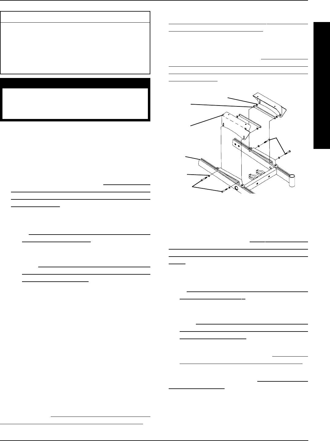
33
This Procedure Includes the Following:
Replacing Seat Mounting Plates
Replacing Seat Support Brackets
Replacing Seat Support Bracket T-Nuts
Replacing Battery Charger Bracket and T-Nut
Removing/Installing Seat Stop Screws
WARNING
After ANY adjustments, repair or service and BE-
FORE use, make sure that all attaching hardware
is tightened securely - otherwise injury or dam-
age may result.
REPLACING SEAT MOUNTING
PLATES (FIGURE 1)
NOTE: When replacing components of the wheelchair, refer
to the individual procedure for correct use of LOCTITE 242
and torque specifications or PROCEDURE 3 of this Manual.
1. Perform the instructions outlined in PREPARATIONS
FOR REMOVING/INSTALLING SEAT FRAME (STAN-
DARD FRAME, ADJUSTABLE FRAME, AND CAP-
TAINS VAN SEAT) in PROCEDURE 6 of this manual.
2. Perform one (1) of the following:
A. Remove standard seat frame subassembly. Refer
to REMOVING/INSTALLING STANDARD SEAT
FRAME SUBASSEMBLY in PROCEDURE 6 of
this manual.
B. Remove adjustable seat frame subassembly. Re-
fer to INSTALLING/REMOVING ADJUSTABLE
SEAT FRAME ASSEMBLY AND OR COMPO-
NENT REPLACEMENT in PROCEDURE 6 of
this manual.
C. Remove captains van seat. Refer to INSTALLING/
REMOVING CAPTAINS VAN SEAT ASSEMBLY in
PROCEDURE 6 of this manual.
NOTE: Before removing seat mounting plates, note the po-
sition of the washers.
3. Remove the two (2) mounting screws, washers and
bolt strap bracket that secure the seat mounting plate to
the seat support bracket.
4. Secure NEW seat mounting plate with existing two (2)
mounting screws, washers, and bolt straps to seat sup-
port bracket using Loctite 242 and torque to 156-inch
pounds.
5. Repeat STEPS 1-2 for opposite side, if necessary.
NOTE: For illustrations of the three (3) different seat mount-
ing plates, refer to MOUNTING PLATE - SEAT ANGLE
ADJUSTMENT AND INSTALLATION ORIENTATION in
PROCEDURE 6 of this manual.
Washer
Washer
Mounting
Screws
Seat
Mounting
Plate
Bolt Strap
FIGURE 1 - REPLACING SEAT MOUNTING PLATES
6. Adjust seat mounting plates to desired angle. Refer to
MOUNTING PLATE - SEAT ANGLE ADJUSTMENT
AND INSTALLATION ORIENTATION in PROCEDURE
6 of this manual.
7. Reverse STEP 2A, 2B or 2C.
8. Perform the instructions outlined in PREPARATIONS
FOR REMOVING/INSTALLING SEAT FRAME (STAN-
DARD FRAME, ADJUSTABLE FRAME, AND CAP-
TAINS VAN SEAT) in PROCEDURE 6 of this manual.
Seat
Support
Bracket
Mounting
Screws
REPLACING SEAT SUPPORT
BRACKETS (FIGURE 2)
1. Perform the instructions outlined in PREPARATIONS FOR
REMOVING/INSTALLING SEAT FRAME (STANDARD
FRAME, ADJUSTABLE FRAME, AND CAPTAINS VAN
SEAT) in PROCEDURE 6 of this manual.
2. Perform one (1) of the following:
A. Remove standard seat frame subassembly. Refer
to REMOVING/INSTALLING STANDARD SEAT
FRAME SUBASSEMBLY in PROCEDURE 6 of this
manual.
B. Remove adjustable seat frame subassembly. Re-
fer to INSTALLING/REMOVING ADJUSTABLE
SEAT FRAME ASSEMBLY AND OR COMPO-
NENT REPLACEMENT in PROCEDURE 6 of
this manual.
C. Remove captains van seat. Refer to INSTALLING/
REMOVING CAPTAINS VAN SEAT ASSEMBLY in
PROCEDURE 6 of this manual.
3. Remove seat mount plates. Refer to REPLACING SEAT
MOUNTING PLATES in this procedure of the manual.
NOTE: Note the position of the seat support brackets before
removing to ensure proper reinstallation.
BASE FRAME PROCEDURE 7
B
A
S
E
F
R
A
M
E
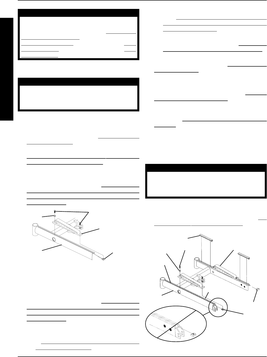
34
BASE FRAMEPROCEDURE 7
B
A
S
E
F
R
A
M
E
B. Remove adjustable seat frame subassembly. Re-
fer to INSTALLING/REMOVING ADJUSTABLE
SEAT FRAME ASSEMBLY AND OR COMPO-
NENT REPLACEMENT in PROCEDURE 6 of
this manual.
C. Remove captains van seat. Refer to INSTALLING/
REMOVING CAPTAINS VAN SEAT ASSEMBLY in
PROCEDURE 6 of this manual.
3. Remove the seat mount plates. Refer to REPLACING SEAT
MOUNTING PLATES in this procedure of the manual.
NOTE: Before removing seat mounting plates, note the po-
sition of the washers.
4. Remove the seat support brackets. Refer to REPLAC-
ING SEAT SUPPORT BRACKETS in this procedure of
the manual.
5. Remove the seat stop screw that is closest to the end
cap. Refer to REMOVING/INSTALLING SEAT STOP
SCREWS in this procedure of the manual.
6. Remove the end cap and channel cover.
7. Slide existing T-Nut(s) out of channel.
8. Insert NEW T-Nut(s) into channel in correct orientation.
9. Replace channel cover and end cap.
WARNING
The seat stop screws must be in place be-
fore operation of your power wheelchair.
Ensure the T-Nut(s) are positioned between
both seat stop screws.
10. Use Loctite 242 and reinstall seat stop screw into base
frame.
11. Reinstall the seat seat support brackets. Refer to RE-
PLACING SEAT SUPPORT BRACKETS in this pro-
cedure of the manual.
FIGURE 2 - REPLACING SEAT SUPPORT BRACKETS
Washer
Seat Support
Bracket
Base
Frame
Mounting Screws
T-Nut
WARNING
Do not adjust the position of the seat sup-
port bracket in this procedure. If an ad-
justment is desired, refer to ADJUSTING
WEIGHT DISTRIBUTION in PROCEDURE 15 -
MWD WHEELCHAIRS, PROCEDURE 16 - RWD
WHEELCHAIRS, or PROCEDURE 17 - FWD
WHEELCHAIRS of this manual.
4. Remove the two (2) mounting screws and washers that
secure the seat support bracket to the base frame.
WARNING
When installing seat support bracket, en-
sure the mounting screws are threaded
into the T-Nuts located inside the channel
of the base frame.
5. Secure the NEW seat support bracket to base frame
with the existing two (2) mounting screws and washers.
Torque to 156-inch pounds.
6. Reinstall seat mount plates. Refer to REPLACING SEAT
MOUNTING PLATES in this procedure of the manual.
7. Adjust seat mount plates to desired angle. Refer to
MOUNTING PLATE - SEAT ANGLE ADJUSTMENT
AND INSTALLATION ORIENTATION in PROCEDURE
6 of this manual.
8. Reverse STEP 2A, 2B or 2C.
9. Perform the instructions outlined in PREPARATIONS
FOR REMOVING/INSTALLING SEAT FRAME (STAN-
DARD FRAME, ADJUSTABLE FRAME, AND CAP-
TAINS VAN SEAT) in PROCEDURE 6 of this manual.
REPLACING SEAT SUPPORT
BRACKET T-NUTS (FIGURE 3)
1. Perform the instructions outlined in PREPARATIONS
FOR REMOVING/INSTALLING SEAT FRAME (STAN-
DARD FRAME, ADJUSTABLE FRAME, AND CAP-
TAINS VAN SEAT) in PROCEDURE 6 of this manual.
2. Perform one (1) of the following:
A. Remove standard seat frame subassembly. Refer
to REMOVING/INSTALLING STANDARD SEAT
FRAME SUBASSEMBLY in PROCEDURE 6 of
this manual.
FIGURE 3 - REPLACING SEAT SUPPORT BRACKET
T-NUTS
Channel Cover
Mounting Screw
T-Nut
End Cap
Seat Support
Bracket
Base
Frame
Channel
Stop
Screw
Washer

35
8. Secure the battery charger connector to the mount
bracket with the EXISTING two (2) mounting screws.
Tighten securely.
9. Reverse STEP 2A, 2B or 2C.
10. Perform the instructions outlined in PREPARATIONS
FOR REMOVING/INSTALLING SEAT FRAME (STAN-
DARD FRAME, ADJUSTABLE FRAME, AND CAP-
TAINS VAN SEAT) in PROCEDURE 6 of this manual.
12. Reinstall the seat mount plates. Refer to REPLACING
SEAT MOUNTING PLATES in this procedure of the
manual.
13. Adjust seat mounting plates to desired angle. Refer to
MOUNTING PLATE - SEAT ANGLE ADJUSTMENT
AND INSTALLATION ORIENTATION in PROCEDURE
6 of this manual.
14. Reverse STEP 2A, 2B or 2C.
15. Perform the instructions outlined in PREPARATIONS
FOR REMOVING/INSTALLING SEAT FRAME (STAN-
DARD FRAME, ADJUSTABLE FRAME, AND CAP-
TAINS VAN SEAT) in PROCEDURE 6 of this manual.
REPLACING BATTERY CHARGER
BRACKET AND T-NUT
NOTE: There is no T-nut on the FWD models.
RWD and MWD Models (FIGURE 4)
1. Perform the instructions outlined in PREPARATIONS
FOR REMOVING/INSTALLING THE SEAT FRAME
(STANDARD FRAME, ADJUSTABLE FRAME, AND
CAPTAINS VAN SEAT) in PROCEDURE 6 of this
manual.
2. Perform one (1) of the following:
A. Remove standard seat frame subassembly. Refer
to REMOVING/INSTALLING STANDARD SEAT
FRAME SUBASSEMBLY in PROCEDURE 6 of
this manual.
B. Remove adjustable seat frame subassembly. Re-
fer to INSTALLING/REMOVING ADJUSTABLE
SEAT FRAME ASSEMBLY AND OR COMPO-
NENT REPLACEMENT in PROCEDURE 6 of
this manual.
C. Remove captains van seat. Refer to INSTALLING/
REMOVING CAPTAINS VAN SEAT ASSEMBLY in
PROCEDURE 6 of this manual.
3. Remove the seat support brackets. Refer to RE-
PLACING SEAT SUPPORT BRACKETS in this
procedure of this manual.
4. Remove the two (2) mounting screws that secure the
battery charger connector to the mount bracket.
5. Remove battery charger connector from mount bracket.
6. Remove the mounting screw which secures the battery
charger mount bracket to the T-nut located in the chan-
nel of the base frame.
7. Replace battery charger mount bracket and secure to
base frame with existing mounting screw.
NOTE: To replace the Battery Charger Bracket T-Nut, per-
form STEPS 3-13 in REPLACING SEAT SUPPORT
BRACKET T-NUTS in this procedure of the manual.
FIGURE 4 - RWD AND MWD MODELS
Battery
Charger
Connector
Battery
Charger
Mount
Bracket
Base
Frame
T-nut
Mounting Screw
BASE FRAME PROCEDURE 7
B
A
S
E
F
R
A
M
E
Arrow FWD Model (FIGURE 5)
1. Perform one (1) of the following:
A. For LOW MOUNT BRACKETS, perform
STEPS 1-11.
B. For MEDIUM/HIGH MOUNT BRACKETS per-
form STEPS 4-9 ONLY.
2. Perform the instructions outlined in PREPARATIONS
FOR REMOVING/INSTALLING THE SEAT FRAME
(STANDARD FRAME, ADJUSTABLE FRAME, AND
CAPTAINS VAN SEAT) in PROCEDURE 6 of this
manual.
3. Perform one (1) of the following:
A. Remove standard seat frame subassembly. Refer
to REMOVING/INSTALLING STANDARD SEAT
FRAME SUBASSEMBLY in PROCEDURE 6 of
this manual.
B. Remove adjustable seat frame subassembly. Re-
fer to INSTALLING/REMOVING ADJUSTABLE
SEAT FRAME ASSEMBLY AND OR COMPO-
NENT REPLACEMENT in PROCEDURE 6 of
this manual.
C. Remove captains van seat. Refer to INSTALLING/
REMOVING CAPTAINS VAN SEAT ASSEMBLY in
PROCEDURE 6 of this manual.
4. Remove the front shroud. Refer to REMOVING/IN-
STALLING FRONT SHROUD in PROCEDURE 17
of the manual.
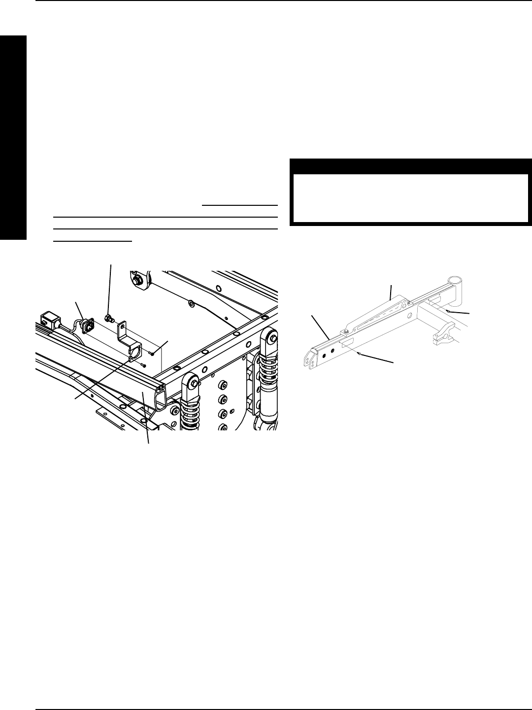
36
FIGURE 6 - REMOVING/INSTALLING SEAT
STOP SCREWS
Base
Frame
Front Seat Stop Screw
Rear Seat
Stop Screw
Seat Support Bracket
REMOVING/INSTALLING SEAT
STOP SCREWS (FIGURE 6)
NOTE: This procedure is for RWD and MWD wheel-
chairs ONLY.
NOTE: The front seat stop screw should only be removed
if replacing a T-nut for either the seat support bracket or
the battery charger mount bracket. The rear seat stop
screw should never be removed.
1. Unthread seat stop screw from base frame.
WARNING
The seat stop screws must be in place be-
fore operation of your power wheelchair.
Ensure the seat support bracket is posi
tioned between both seat stop screws.
2. When reinstalling the front seat stop screw, ensure
the seat support bracket is located in-between both
seat stop screws. Use loctite 242 and tighten securely.
5. Remove the two (2) mounting screws that secure the
battery charger connector to the mount bracket.
6. Remove battery charger connector from mount bracket.
7. Remove the mounting screw which secures the battery
charger mount bracket to the base frame.
8. Replace the battery charger mount bracket and se-
cure it to the base frame with the EXISTING mounting
screw. Securely tighten.
9. Secure the battery charger connector to the mount
bracket with the EXISTING two (2) mounting screws.
Tighten securely.
10. Reverse STEP 3A, 3B or 3C.
11. Perform the instructions outlined in PREPARATIONS
FOR REMOVING/INSTALLING SEAT FRAME (STAN-
DARD FRAME, ADJUSTABLE FRAME, AND CAP-
TAINS VAN SEAT) in PROCEDURE 6 of this manual.
FIGURE 5 - ARROW FWD MODEL
Mounting
Screw
Mounting Screw
Base Frame
Battery
Charger
Mount
Bracket
Battery
Charger
Connector
BASE FRAMEPROCEDURE 7
B
A
S
E
F
R
A
M
E
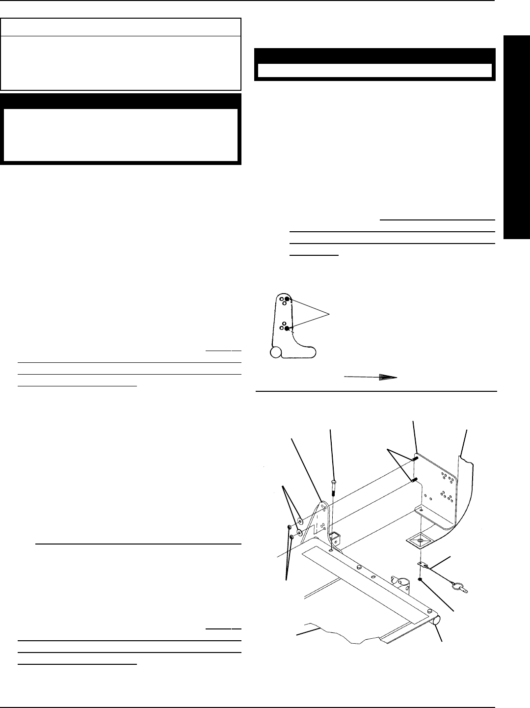
37
PROCEDURE 8
B
A
C
K
F
R
A
M
E
This Procedure includes the following:
Removing/Installing CJ Back Brackets
Changing Back Height
Back Angle Adjustment
WARNING
After ANY adjustments, repair or service
and BEFORE use, make sure that all attach-
ing hardware is tightened securely - oth-
erwise injury or damage may result.
NOTE: The procedures in this section of the manual refer
to NON-RECLINER seat frames only. For recliner seat
frames, refer to PROCEDURE 14 of this manual.
REMOVING/INSTALLING CJ BACK
BRACKETS (FIGURE 1)
NOTE: The following procedure is for Jr. wheelchairs only.
NOTE: This procedure is to be performed in conjunction with
a starting procedure except when replacement of CJ back
brackets is desired.
Removing CJ Back Brackets
1. If necessary, perform the instructions outlined in PREPA-
RATIONS FOR REMOVING/INSTALLING SEAT
FRAME (STANDARD FRAME, ADJUSTABLE FRAME,
AND CAPTAINS VAN SEAT) in PROCEDURE 6 of this
manual.
2. Remove the locknuts and washers that secure the CJ
back bracket to the back angle plate.
3. Remove the mounting screw and locknut that secures
the quick release pin and CJ back bracket and seat po-
sitioning strap to the seat frame.
4. Remove the existing CJ back bracket.
5. Repeat STEPS 2-4 for the opposite CJ back bracket.
6. Perform one (1) of the following:
A. For replacement of CJ back brackets, proceed to
REMOVING/INSTALLING CJ BACK BRACKETS
in this procedure of the manual.
B. For all other seat frame changes, refer back to the
starting procedure to complete the desired change.
Installing CJ Back Brackets
1. If necessary, perform the instructions outlined in PREPA-
RATIONS FOR REMOVING/INSTALLING SEAT
FRAME (STANDARD FRAME, ADJUSTABLE FRAME,
AND CAPTAINS VAN SEAT) in PROCEDURE 6 of this
manual.
2. Install the threaded studs of the CJ back bracket through
the back angle plates as shown in FIGURE 1.
BACK FRAME
NOTE: Ensure the CJ back bracket is mounted in the front
holes of the back angle plates as shown in DETAIL A.
WARNING
Always wear your seat positioning strap.
3. Position the seat positioning strap and quick release pin
under the CJ back bracket.
4. Secure the quick release pin, seat positioning strap, and
CJ back bracket to the seat frame. Torque to 75-inch
pounds.
5. Install washers and locknuts onto the threaded studs of
the CJ back bracket. Torque to 75-inch pounds.
6. Perform one (1) of the following:
A. For replacing CJ back brackets only, perform the
instructions outlined in PREPARATIONS FOR RE-
MOVING/INSTALLING SEAT FRAME (STANDARD
FRAME, ADJUSTABLE FRAME, AND CAPTAINS
VAN SEAT) in PROCEDURE 6 of this manual.
B. For all other seat frame changes, refer back to the
starting procedure to complete the desired change.
Mounting
Screw
Locknut
Quick
Release
Pin
Back
Angle
Plate
Seat Frame
Washers
Locknuts
CJ Back
Bracket
Seat
Positioning
Strap
FIGURE 1 - REMOVING/INSTALLING CJ BACK
BRACKETS
Toward Front of
Wheelchair
CJ Bracket
mounts in
Front Holes on
Back Angle
Plates.
DETAIL “A”
Threaded
Studs
Seat
Pan

38
NOTE: If needing a reference for proper mounting holes
for the back angle required, or if changing the original back
angle, refer to BACK ANGLE ADJUSTMENT in this pro-
cedure of the manual.
WARNING
The back canes MUST be fastened se-
curely to the seat frame BEFORE using the
wheelchair. Torque to 75-inch pounds.
13. Secure the two (2) NEW back canes to the seat frame
with the existing four (4) mounting screws, washers,
spacers, and locknuts. Use Loctite 242 and torque to
75-inch pounds.
14. Secure the top of the existing/new back upholstery to
the back canes with the two (2) existing mounting
screws and washers.
15. Secure bottom of the existing/NEW back upholstery
to rear of the seat pan.
16. Secure the bottom of the existing/NEW back uphol-
stery to the back canes with new tie-wraps.
NOTE: Clean upholstery with warm DAMP cloth and mild
detergent to remove superficial soil.
WARNING
Laundering or moisture will reduce flame
retardancy of the upholstery.
NOTE: When replacing the back upholstery, back as-
sembly or changing back height, follow these guidelines
for spreader bar height (where applicable):
BACK HEIGHT u SPREADER BAR
HEIGHT
16-inches* 5-inches
17-inches* 5-inches
18-19-inches* 7-inches
20-24inches 7-inches
NOTE: Spreader Bar required on back heights 20-24-
inches. *Spreader bar ONLY required on these back
heights if the width or depth of the chair exceeds 19-inches.
u Height of Spreader Bar from Bottom of Back Canes
to Top of Spreader Bar Clamp.
HEAVY DUTY MODELS
NOTE: Spreader bar required on all Heavy Duty models.
BACK HEIGHT u SPREADER BAR
HEIGHT
16-17-inches 5-inches
18-24-inches 7-inches
uHeight of Spreader Bar from Bottom of Back
Canes to Top of Spreader Bar Clamp.
CHANGING BACK HEIGHT
(FIGURE 2)
NOTE: If changing the back height, new back upholstery
may be needed as well. Refer to the following chart to deter-
mine if new back upholstery is needed:
BACK UPHOLSTERY HEIGHT RANGES
16-17-INCHES
18-19-INCHES
20-INCHES
21-22-INCHES
23-24-INCHES
If back height required is within the range of the origi-
nal back height, only new back canes will be needed.
If the back height required is NOT within the range of
the original back height, new back upholstery, as well
as new back canes will be needed.
NOTE: Existing hardware and inserts will be reused.
1. Remove the armrests from the wheelchair. Refer to IN-
STALLING/REMOVING FLIP BACK ARMRESTS in
PROCEDURE 4 of the owners manual, 1081227.
NOTE: Note the correct mounting screw mounting positions
to ensure the proper back angle for reinstallation.
2. Remove the two (2) mounting screws and washers that
secure the existing back upholstery to the back canes.
3. Remove the four (4) mounting screws, washers, spac-
ers, and locknuts that secure the existing back canes to
the seat frame.
4. Remove the inserts from the existing back canes.
5. Remove the back assembly from the wheelchair.
6. If applicable, loosen, but do not remove the mounting
screws and locknuts that secure the spreader bar to the
existing back canes.
7. Remove existing back canes from the back assembly.
8. Slide the inserts into the bottom of the NEW back canes.
9. Line up the mounting holes of the inserts with the mount-
ing holes in the back canes.
NOTE: To keep the inserts lined up for reinstallation onto the
wheelchair, start one (1) of the mounting screws through the
back cane from inside of the wheelchair to hold the insert in
place.
10. Slide the NEW back canes through the existing/NEW
back upholstery and spreader bar.
11. If applicable, loosely tighten the mounting screws that
secure the spreader bar to the NEW back canes.
12. Line up the mounting holes in the back canes with the
mounting holes in the seat frame.
BACK FRAMEPROCEDURE 8
B
A
C
K
F
R
A
M
E
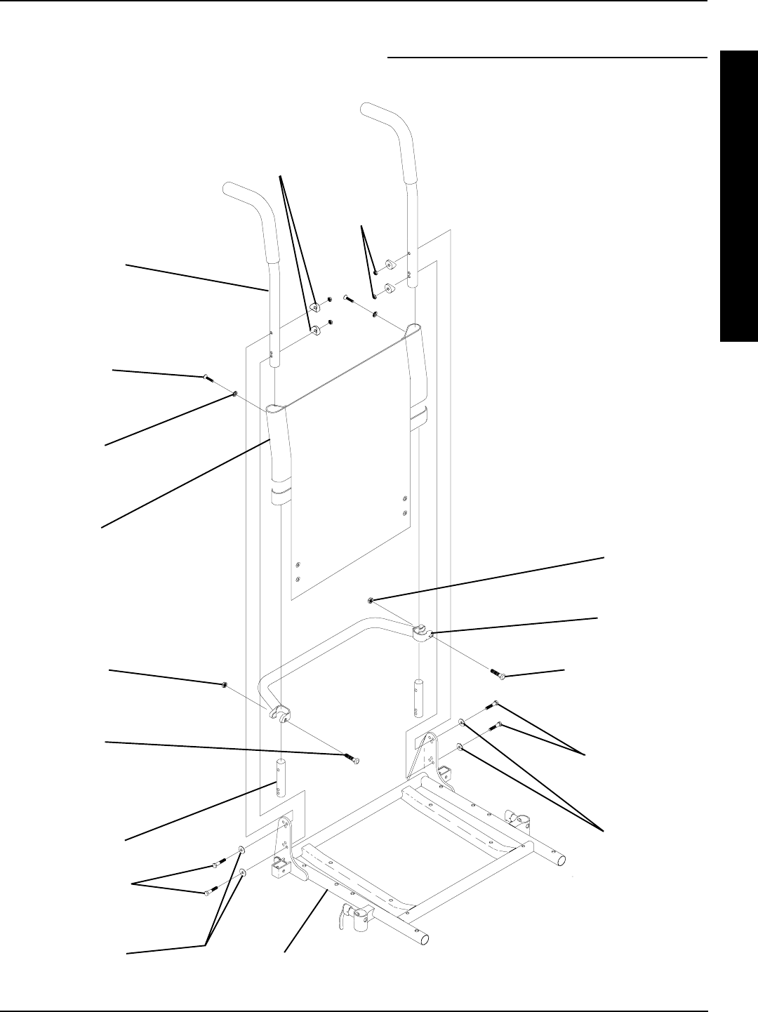
39
FIGURE 2 - CHANGING BACK HEIGHT
Locknut
(STEPS 6,11)
Mounting Screw
Torque to 60 in/lbs
(STEPS 6,11)
Spreader Bar
(STEPS 6,17)
Mounting
Screw
(STEPS 2, 14)
Washer
(STEPS 2, 14)
Back
Upholstery
Back Cane
(STEPS 3, 10)
Insert
(STEPS 4,8)
Seat Frame
Mounting Screws
Torque to 75 in/lbs
(STEPS 3, 13)
Washers
(STEPS 3, 13)
Mounting Screws
(STEPS 3, 13)
Washers
(STEPS 3, 13)
Spacers
(STEPS 3, 13)
Locknuts
(STEPS 3, 13)
Locknut
(STEPS 6,11)
Mounting
Screw
(STEPS 6,11)
17. If necessary, reposition the spreader bar at the cor-
rect height for the corresponding back height and
torque the mounting hardware to 60-inch pounds.
18. Reinstall the armrest onto the wheelchair. Refer to
INSTALLING/REMOVING FLIP BACK ARMRESTS
in PROCEDURE 4 of the owners manual, 1081227.
BACK FRAME PROCEDURE 8
B
A
C
K
F
R
A
M
E

40
BACK ANGLE ADJUSTMENT
(FIGURE 3)
1. Remove armrests from the wheelchair. Refer to IN-
STALLING/REMOVING FLIP BACK ARMRESTS in
PROCEDURE 4 of the owners manual, 1081227.
2. Remove the mounting screw and washer from the top
mounting hole of back angle plate and back cane.
NOTE: To avoid losing the insert in each back cane, thread
the mounting screw through the cane from the inside of
wheelchair to hold the insert in place.
TO ACHIEVE A BACK ANGLE OF:
ANGLE BACK CANE MOUNTING HOLE BACK ANGLE PLATE HOLE
80OTop TOP Front
Bottom BOTTOM Rear
85OTop TOP Front
2nd from Bottom BOTTOM Center
90OTop TOP Front
Bottom BOTTOM Front
95OTop TOP Center
2nd from Bottom BOTTOM Front
100OTop TOP Rear
Bottom BOTTOM Front
FIGURE 3 - BACK ANGLE ADJUSTMENT
3. Remove the mounting screw and washer from the
bottom mounting hole of the back angle plate and
back cane.
4. Reposition the back canes into the correct mount-
ing holes of the back angle plate to obtain a back
angle between 80o and 100o in 5o increments.
5. Torque mounting screws to 75-inch pounds.
6. Reinstall the armrests onto the wheelchair. Refer
to INSTALLING/REMOVING FLIP BACK ARM-
RESTS in PROCEDURE 4 of the owners manual,
1081227.
BACK FRAMEPROCEDURE 8
B
A
C
K
F
R
A
M
E
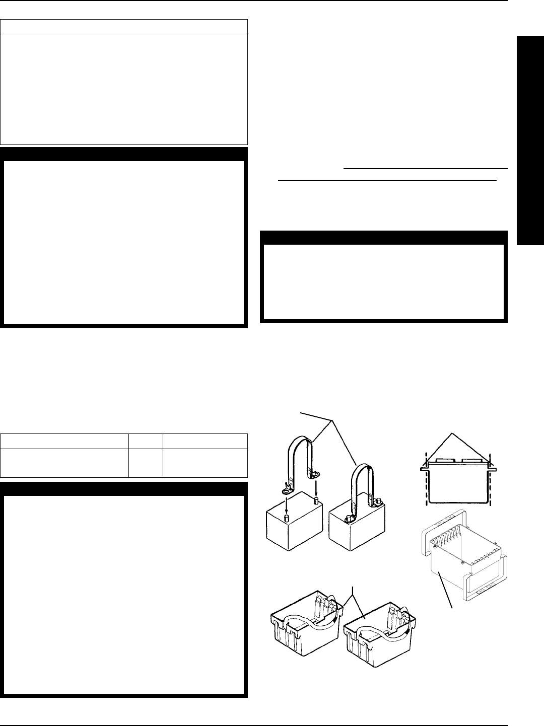
41
NOTE: If there is battery acid in the bottom or on the sides of
the battery box(es) or battery(ies), apply baking soda to these
areas to neutralize the battery acid. Before reinstalling the
NEW or existing battery(ies), clean the baking soda from the
battery box(es) or battery(ies).
NOTE: When securing battery lifting strap to battery, ob-
serve polarity markings located on the ends of the battery
lifting strap, (+) side to POSITIVE (+) battery post and (-) side
to NEGATIVE (-) battery post.
1. If necessary, remove the battery boxes from the wheel-
chair. Refer to INSTALLING/REMOVING BATTERY
BOXES - GROUP 24 BATTERY BASE FRAMES in
this procedure of the manual.
2. Secure battery lifting strap to battery terminal(s)/post(s)
(FIGURE 1).
CAUTION
Some battery manufacturers mold a carrying strap
and/or hold down flanges directly into the bat-
tery case. Batteries which interfere with the bat-
tery box cannot be used for these applications.
Attempting to “wedge” a battery into a battery
box may damage the box and/or the battery.
3. Place batteries into battery box bottom.
PROCEDURE 9BATTERIES
B
A
T
T
E
R
I
E
S
This Procedure Includes the Following:
Installing/Removing Batteries Into/From Battery
Box(es)
Connecting Battery Cables
When to Charge Batteries
Charging Batteries
Replacing Batteries
Installing/Removing Group 24 Battery Boxes
Installing/Removing Group 22NF Battery Boxes
WARNING
Make sure power to the wheelchair is OFF before
performing this procedure.
The use of rubber gloves and chemical
goggles or face shields is recommended
when working with batteries.
Invacare strongly recommends that battery instal-
lation and battery replacement ALWAYS be done
by a qualified technician.
After ANY adjustments, repair or service and BE-
FORE use, make sure all attaching hardware is
tightened securely - otherwise injury or damage
may result.
INSTALLING/REMOVING
BATTERIES INTO/FROM BATTERY
BOXES (FIGURE 1)
NOTE: To remove the battery(ies) from the battery box(es),
reverse the following procedure.
NOTE: Have the following tools available:
TOOL QTY COMMENTS
Battery Lifting Strap 1 Supplied
1/2-inch (6 pt) Box Wrench 1 Not Supplied
WARNING
ALWAYS use a battery lifting strap when lifting a bat-
tery. It is the most convenient method and assures
that the battery acid will not spill. It also helps to
prolong the life of the battery.
DO NOT tip the batteries. Keep the batteries in an
upright position.
Place the wheelchair in a well ventilated area
where work can be performed without risking
damage to carpeting or floor covering.
The warranty and performance specifications con-
tained in this manual are based on the use of deep
cycle gel cell or sealed lead acid batteries.
Invacare strongly recommends their use as the
power source for this unit.
Battery
Lifting
Strap
Group 22NF
Battery Box
Bottom
Group 24
Battery Box Bottom
Molded Carrying Straps (Must be
removed before installation)
FIGURE 1 - INSTALLING/REMOVING BATTERIES
INTO/FROM BATTERY BOXES

42
PROCEDURE 9 BATTERIES
B
A
T
T
E
R
I
E
S
CONNECTING BATTERY CABLES
(FIGURE 2)
WARNING
NEVER allow any of your tools and/or battery
cable(s) to contact BOTH battery post(s) at the
same time. An electrical short may occur and se-
rious personal injury or damage may occur.
The use of rubber gloves and chemical
goggles or face shields is recommended
when working with batteries.
When tightening the clamps, always use a
box wrench. Pliers will “round off” the nuts.
NEVER wiggle the battery terminal(s)/post(s)
when tightening. The battery may become
damaged.
The POSITIVE (+) RED battery cable MUST con-
nect to the POSITIVE (+) battery terminal(s)/
post(s), otherwise serious damage will occur
to the electrical system.
Group 24 Batteries
NOTE: Perform this procedure on one (1) battery and bat-
tery box at a time. Repeat procedure for other battery box.
1. Position battery box top next to battery box bottom as
shown in FIGURE 2.
2. Peel back battery clamp covers to expose battery clamp
on each battery cable as follows:
A. RED battery clamp cover from RED battery cable.
B. BLACK battery clamp cover from BLACK battery
cable.
3. Connect NEGATIVE N battery cable clamp to NEGA-
TIVE(-) battery post and connect POSITIVE P battery
cable clamp to POSITIVE (+) battery post (DETAIL A).
4. Secure the battery cable clamp(s) to the battery post(s)
with provided hex screws and nuts. Securely tighten.
5. Verify battery cable clamps(s) are correctly installed
and securely tightened.
6. Reposition battery clamp covers over battery post(s).
7. Install the battery box top(s).
9. Install the battery box(es) into the wheelchair. Refer to
INSTALLING/REMOVING BATTERY BOX(ES) in this
procedure of this manual.
NOTE: New Battery(ies) MUST be fully charged BEFORE
using, otherwise the life of the battery(ies) will be reduced.
10. If necessary, charge the battery(ies). Refer to CHARG-
ING BATTERIES in this procedure of the manual.
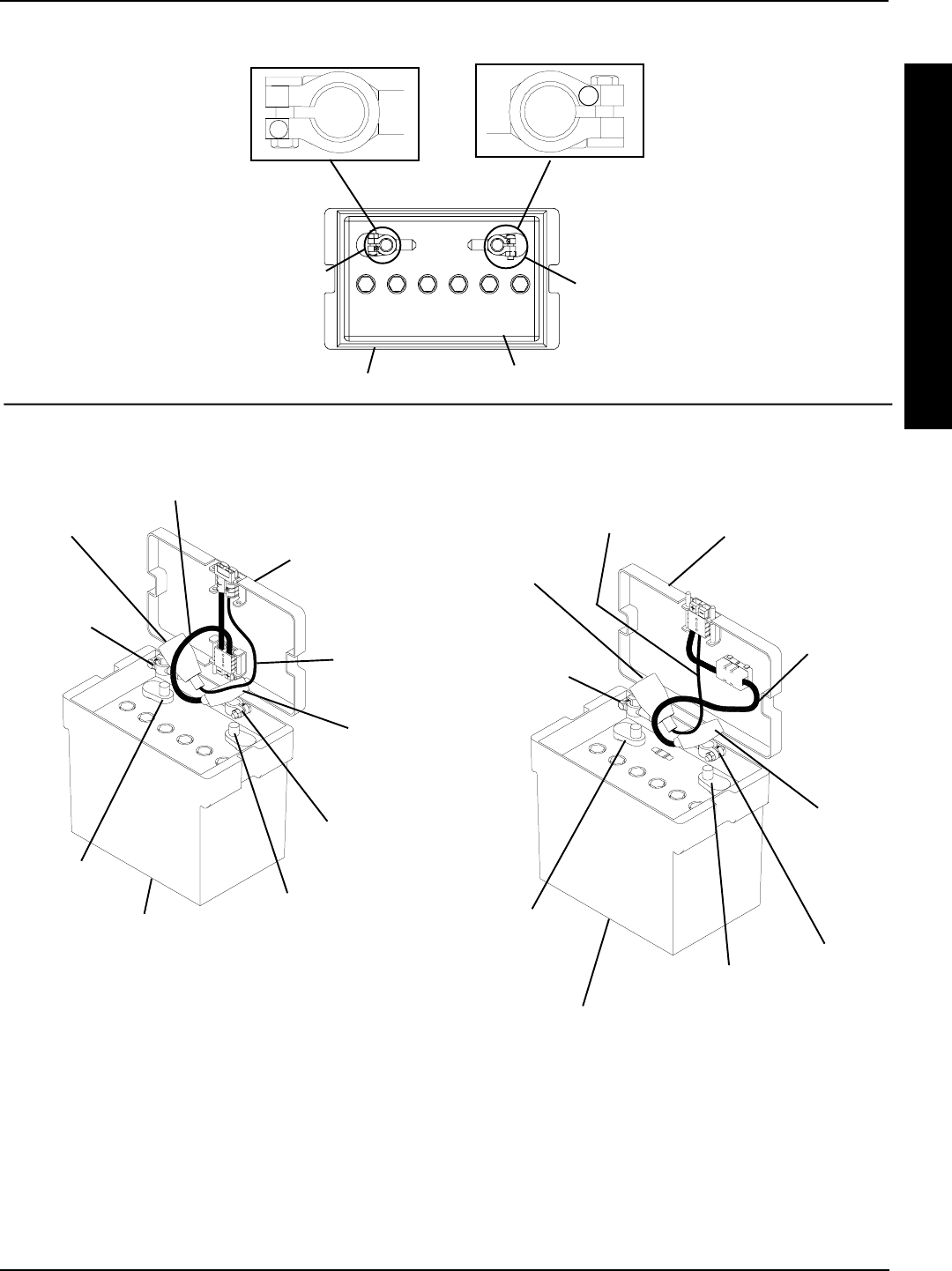
43
PROCEDURE 9BATTERIES
B
A
T
T
E
R
I
E
S
P
N
FIGURE 2 - CONNECTING BATTERY CABLE(S) - GROUP 24 BATTERIES
Battery Box Bottom
POSITIVE
(+)
Battery
Terminal/
Post
NEGATIVE
(-)
Battery
Terminal/
Post
Battery
ONE (1) CONNECTOR BATTERY BOXTWO (2) CONNECTOR BATTERY BOX
BLACK
Battery
Clamp
Cover
RED
Battery
Clamp
Cover
Red POSI-
TIVE (+)
Battery Cable
Clamp
Black NEGA-
TIVE (-)
Battery Cable
Clamp
Black NEGA-
TIVE (-)
Battery Cable
RED POSI-
TIVE (+)
Battery
Cable
One (1) Connector
Battery Box Top
Battery Box
Bottom
RED
Battery
Clamp
Cover
RED
POSITIVE (+)
Battery
Cable Clamp
Black
NEGATIVE (-)
Battery
Cable
Clamp
RED POSITIVE (+)
Battery Cable
BLACK
NEGATIVE (-)
Battery
Cable
Two (2) Connector
Battery Box Top
Battery Box
Bottom
DETAIL “A”
NEGATIVE (-)
Battery
Terminal/Post
POSITIVE (+)
Battery
Terminal/Post
NEGATIVE (-)
Battery Termi-
nal/Post POSITIVE (+)
Battery Terminal/Post

44
B
A
T
T
E
R
I
E
S
Group 22 Battery Base Frames (FIGURE 3)
NOTE: Refer to WARNINGSand CAUTIONS in the front
of this procedure.
NOTE: Note polarity of white battery cable (jumper)
battery terminal ends.
1. Remove battery terminal cap(s) from battery
terminal(s) ends. Refer to DETAIL A in FIGURE
3.
2. Connect WHITE battery cable (jumper) NEGATIVE
N terminal end to NEGATIVE (-) battery terminal/
post of front battery and connect POSITIVE P ter-
minal end to POSITIVE (+) battery terminal/post of
rear battery.
3. Place battery top upside down on top of rear bat-
tery.
4. Connect NEGATIVE (-) BLACK battery cable of
the battery box top to NEGATIVE (-) battery termi-
nal/post of rear battery.
5. Position battery box top right side up and rotate
outward toward right to expose POSITIVE (+) bat-
tery terminal/post of front battery.
6. Connect POSITIVE (+) RED battery cable on battery
box top to POSITIVE (+) battery terminal/post of front
battery.
7. Replace battery terminal cap(s) onto battery cable
terminal end(s).
8. Rotate top toward left into position. Secure in place.
9. Install the battery box into the wheelchair. Refer to
INSTALLING/REMOVING 22NF BATTERY BOX in
the Owners Manual supplied with the chair.
NOTE: New Battery(ies) MUST be fully charged BE-
FORE using, otherwise the life of the battery(ies) will
be reduced.
10. If necessary, charge the battery(ies). Refer to
CHARGING BATTERIES in the Owners Manual
supplied with the wheelchair.
PROCEDURE 9 BATTERIES

45
PROCEDURE 9 BATTERIES
STEPS 3 AND 4
Battery
Box Top
(Under Side
shown)
NEGATIVE (-)
BLACK Battery
Cable
Front
Battery
Rear
Battery
STEPS 5 AND 6
Battery
Box Top
Front
Battery
Battery
Box Bottom
FRONT
POSITIVE (+)
RED Battery
Cable
Fuse
Block
POSITIVE (+) RED Battery Cable
Battery Box Bottom
Rear
Battery
NEGATIVE (-)
Battery
Terminal/Post
POSITIVE (+)
Battery
Terminal/Post
NOTE: Battery box top cut away for clarification pur-
poses only.
FIGURE 3 - CONNECTING BATTERY CABLES - SINGLE 22NF BATTERY BOX
STEP 2
Single
Battery
Box
Bottom
WHITE Bat-
tery Cable
(Jumper)
Front
Battery
Rear
Battery
FRONT
REAR
N
P
DETAIL “A”
Terminal Cap
Terminal End
B
A
T
T
E
R
I
E
S
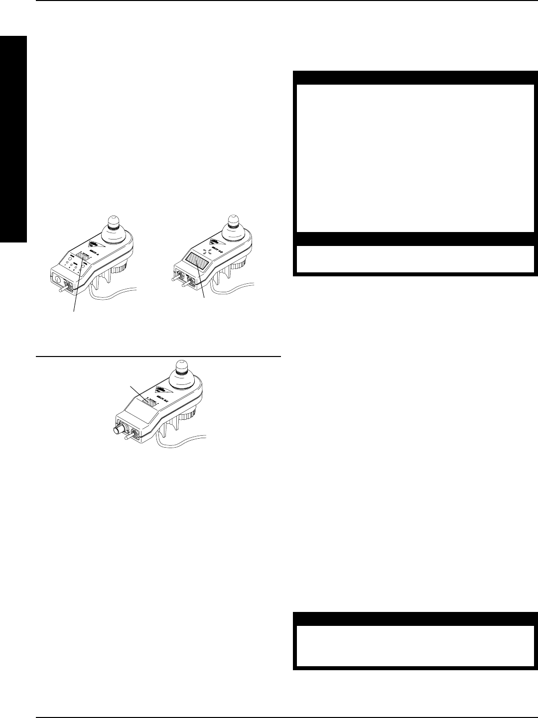
46
PROCEDURE 9 BATTERIES
FIGURE 6 - WHEN TO CHARGE BATTERIES
MKIV- A JOYSTICK MKIV- A+ JOYSTICK
Battery Discharge
Indicator (BDI) (in LCD
Readout)
MKIV- X JOYSTICK
Battery Discharge
Indicator (BDI)
Battery Discharge
Indicator (BDI)
CHARGING BATTERIES (FIGURE 7)
NOTE: New batteries MUST be fully charged prior to initial
use of the wheelchair.
WARNING
Never attempt to recharge the batteries
by attaching cables directly to the bat-
tery terminals or clamps. Always use the
recharging plug located on the side of the
wheelchair frame.
DO NOT attempt to recharge the batter-
ies and operate the power wheelchair at
the same time.
During use and charging, unsealed bat-
teries will vent hydrogen gas which is ex-
plosive in the right concentration with air.
CAUTION
Always charge new batteries before ini-
tial use or battery life will be reduced.
NOTE: As a general rule, batteries should be recharged
daily to assure the longest possible life and minimize
the required charging time. Plan to recharge the bat-
teries when it is anticipated the wheelchair will not be
used for a long period of time.
The range per battery charge using recommended batter-
ies should be approximately 5 to 9 hours of typical opera-
tion. Extensive use on inclines may substantially reduce
per charge mileage.
B
A
T
T
E
R
I
E
S
WHEN TO CHARGE BATTERIES
(FIGURE 6)
The Battery Discharge Indicator (BDI) is a bar graph dis-
play located on the MKIV joystick. It will keep you informed
as to power availability. A visual warning is given before the
power becomes too low to operate the wheelchair. At full
charge the two (2) LEFT segments and the farthest RIGHT
segment of the bar graph will be illuminated. As the battery
becomes discharged, the farthest RIGHT segment will pro-
gressively move to the LEFT until only the last two (2) bars
(LEFT) are illuminated. At this level the last two (2) bars
(LEFT) will start to Flash ON and OFF to indicate that the
end user should charge the batteries as soon as possible.
Description and Use of Battery Chargers
The charger automatically reduces the charge from an ini-
tially high rate to a zero reading at a fully charged condition.
If left unattended, the charger should automatically shut-off
when full charge is obtained.
There are some basic concepts which will help you
understand this automatic process. They are:
The amount of electrical current drawn within a given time
to charge a battery is called the charge rate. If, due to
usage, the charge stored in the battery is low, the charge
rate is high, as indicated by the green light on the charger.
Initially, the green light will stay illuminated for a short period
of time followed by a longer period of off time. As a charge
builds up, the charge rate is reduced, and the green light will
stay illuminated for a longer period of time followed by a
shorter off time.
WARNING
If the charger circuit breaker is tripping ON
and OFF, unplug the charger and contact
Invacare Technical Services, 1-800-832-4707.
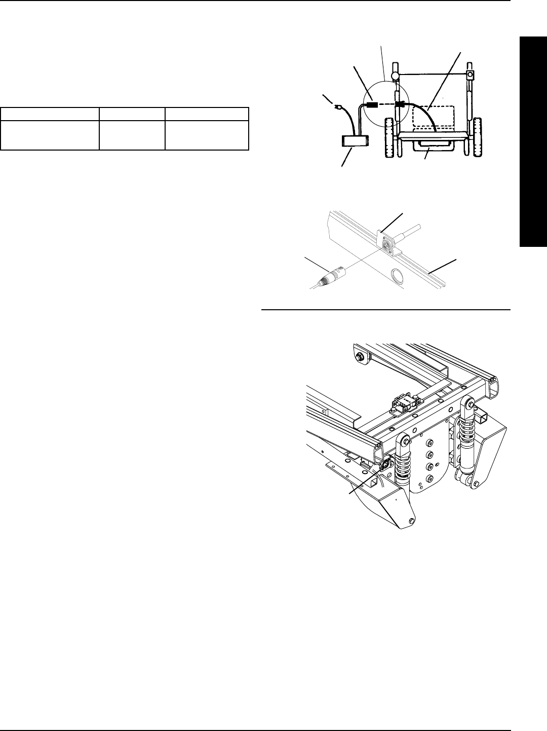
47
NOTE: If performing the charging procedures independently,
READ and CAREFULLY follow the individual instructions
for each charger (supplied or purchased).
NOTE: If charging instructions are not supplied, consult a
qualified service technician for proper procedures.
Required Items:
TOOL QUANTITY COMMENTS
Battery Charger 1 Supplied
uExtension Cord 1 Not Supplied
u(3-prong plug, 15 ampere current rating; industrial type)
1. Attach the battery charger connector to the charger cable/
battery harness.
NOTE: The battery charger connector is factory installed on
the RIGHT side of the wheelchair. It can be positioned on
either side of the wheelchair for user convenience.
NOTE FOR RECLINERS ONLY: If the wheelchair is a re-
cliner, the battery charger connector as well as the limit switch,
are factory set on the RIGHT side of the wheelchair. How-
ever, they can be positioned on either side for user conve-
nience. The limit switch MUST BE positioned on the same
side as the battery charger connector.
2. Plug the chargers AC power cord, or extension, into the
grounded 120 VAC wall outlet.
3. Wait until charging is complete.
B
A
T
T
E
R
I
E
S
FIGURE 7 - CHARGING BATTERIES
Charger Cable
Base Frame
Battery Charger Mount Bracket
RWD/MWD MODELS
ARROW FWD MODEL
NOTE: Shrouds and drive wheels not shown for
clarification purposes only.
From
Battery
Charger
Battery Charger Connector
From Battery Charger
Three (3)
Pronged Plug
Battery Charger Battery Boxes
Top View
of Wheelchair
Battery Charger
Mount Bracket
and Connector
REAR OF
WHEELCHAIR
NOTE: Allow eight (8) hours for normal charging. Larger
batteries (greater than 55 ampere-hours) or severely dis-
charged batteries may require up to sixteen (16) hours to
be properly charged and equalized. If charger operates
for sixteen (16) hours and is unable to fully charge the
batteries, an internal timer turns the charger off and be-
gins to fast blink the green light.
PROCEDURE 9BATTERIES

48
PROCEDURE 9 BATTERIES
B
A
T
T
E
R
I
E
S
It is advantageous to recharge frequently rather than only
when necessary. In fact, a batterys life is extended if the charge
level is maintained well above a low condition.
REPLACING BATTERIES
NOTE: Invacare recommends that both batteries be replaced
if one (1) battery is defective.
Recommended Battery Types
WARNING
The warranty and performance specifi-
cations contained in this manual are
based on the use of deep cycle gel cell
or sealed lead acid batteries. Invacare
strongly recommends their use as the
power source for this unit.
Failure to use the correct battery size and/
or voltage may cause damage to your
wheelchair and give you unsatisfactory
performance.
BATTERY SIZE
POWER CHAIR QTY VOLTS Standard Optional
Arrow
w/ motor/gearbox 2 12 Group 24 Group 22
w/ G/B motor 2 12 Group 22 Group 24
Torque
with motor/gearbox 2 12 Group 22 Group 24
with G/B motor 2 12 Group 22 Group 24
Torque SP
with motor/gearbox 2 12 Group 22 N/A
with G/B motor N/A N/A N/A N/A
Storm X
with motor/gearbox 2 12 Group 22 Group 24
with G/B motor 2 12 Group 22 Group 24
NOTE: G/B denotes gearless/brushless.
NOTE: Both battery sizes are deep cycle batteries.
NOTE: Charge batteries daily. It is critical not to let them run
low at any time.
1. Remove the battery box(es) from the wheelchair. Re-
fer to INSTALLING/REMOVING GROUP 24 BATTERY
BOXES or INSTALLING/REMOVING GROUP 22 BAT-
TERY BOX in this procedure of the manual.
2. Remove the existing batteries from the battery box(es).
Refer to INSTALLING/REMOVING BATTERIES INTO/
FROM BATTERY BOX(ES) in this procedure of the
manual.
3. Clean the new battery terminals. Refer to CLEANING
BATTERY TERMINALS in this procedure of the manual.
4. Install the new batteries into the battery box(es). Refer
to INSTALLING/REMOVING BATTERIES INTO/FROM
BATTERY BOX(ES) in this procedure of the manual.
Cleaning Battery Terminals
WARNING
Most batteries are not sold with instructions.
However, warnings are frequently noted
on the cell caps. Read them carefully.
DO NOT allow the liquid in the battery to
come in contact with skin, clothes or other
possessions. It is a form of acid and harmful
or damaging burns may result. Should the
liquid touch your skin, wash the area IM-
MEDIATELY and thoroughly with cool wa-
ter. In serious cases or if eye contact is
made, seek medical attention IMMEDIATELY.
1. Examine the battery clamps and terminals for corrosion.
2. Verify plastic caps are in place over the battery cell holes.
3. Clean the terminals and inside the battery clamps by
using a battery cleaning tool, wire brush, or medium grade
sand paper.
NOTE: Upon completion, these areas should be shiny,
not dull.
4. Carefully dust off all metal particles.
INSTALLING/REMOVING GROUP
24 BATTERY BOXES (FIGURE 8)
NOTE: To remove the battery boxes from the wheelchair,
reverse the following procedure.
Installing
NOTE: FWD wheelchairs only - Remove the counter-
weight before performing this procedure. Refer to REMOV-
ING/INSTALLING COUNTERWEIGHT in PROCE-
DURE 16 of this manual.
1. Verify that the ON/OFF switch on the joystick is in the
OFF position.
2. Place two (2) connector battery box onto the battery sub-
frame assembly with guide pins facing the inside of the
wheelchair.
3. Slide the two (2) connector battery box along the sub-
frame until its guide pins are engaged in the sub-frame
connector.
4. Secure the battery box carrying strap to the lid of the two
(2) connector battery box.
NOTE: Visually inspect to ensure the connection is prop-
erly made. Connectors MUST be fully engaged.
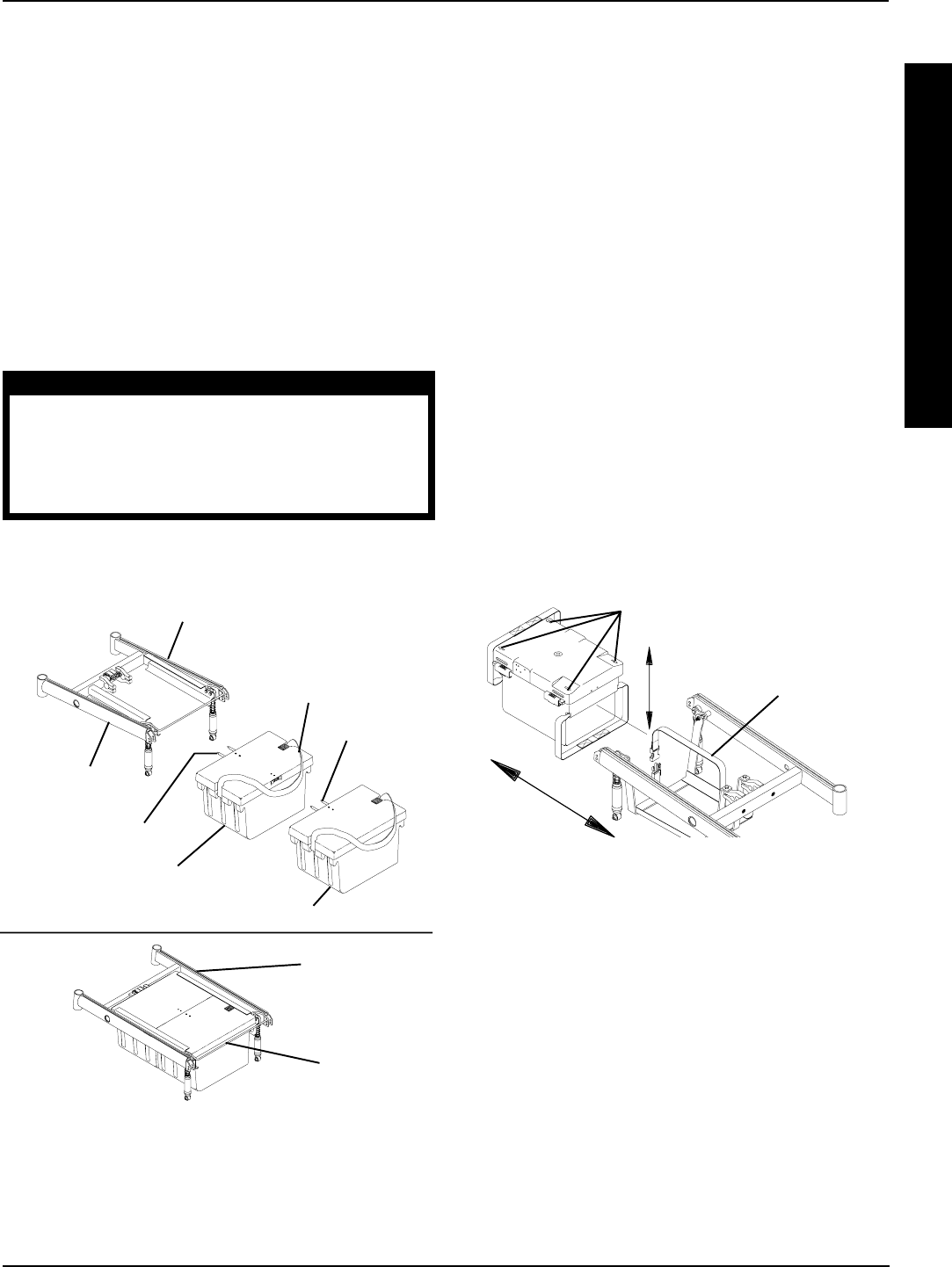
49
B
A
T
T
E
R
I
E
S
FIGURE 9 - INSTALLING/REMOVING GROUP
22 BATTERY BOX
Battery Box
Retention Strap
Arrows
FIGURE 8 - INSTALLING/REMOVING GROUP
24 BATTERY BOXES
Battery Box
Sub-Frame
Two (2) Connector
Battery Box
One (1) Connector Battery Box
NOTE: Position
carrying strap on top
of battery box
Guide Pins
Guide Pins
Battery Box
Retainer Bar
INSTALLING/REMOVING GROUP
22 BATTERY BOX (FIGURE 9)
NOTE: This procedure is for MWD/RWD chairs ONLY.
NOTE: To install the battery box onto the wheelchair, re-
verse the following procedure.
1. Place the wheelchair in a well ventilated area where
work can be performed without risking damage to car-
peting or floor covering.
2. Verify that the ON/OFF switch on the joystick is in the
OFF position.
3. Disconnect the battery cable from the outside of the
battery box.
4. Disconnect the battery box retention strap.
5. Remove the battery box.
6. Slide the four (4) clips that secure the battery box cover
to the battery box to the OPEN position.
NOTE: Arrows on the battery box cover point to the open
position.
7. Remove battery box cover from the battery box.
*NOTE: Illustration depicts base frame for RWD and
MWD models. Batteries remove/Install for the Arrow
FWD in the same manner.
*Base Frame
*Base Frame
NOTE: Make certain that the carrying strap of the first
battery box installed is positioned on top of the battery box
and will not interfere with the second battery box guide
pins during installation.
5. Place one (1) connector battery box onto battery sub-
frame.
6. Slide one (1) connector battery box along the sub-
frame until its guide pins are engaged in the connec-
tor of the two (2) connector battery box.
7. Secure the battery box carrying strap to the lid of the one
(1) connector battery box.
NOTE: Visually inspect to ensure the connection is
properly made. Connectors MUST be fully engaged.
CAUTION
The battery box retainer MUST be locked
(clipped) securely to hold the battery
boxes firmly in place or battery box con-
nectors may be damaged causing er-
ratic chair operation.
8. Pull the battery box retainer down over the end of
front battery box until it is securely clipped (locked)
into place.
PROCEDURE 9BATTERIES

50
PROCEDURE 10 WIRING HARNESS
REMOVING/INSTALLING THE
WIRING HARNESS (FIGURE 1)
NOTE: This procedure is for the FWD and MWD
models ONLY. For the removing and installing the wir-
ing harness on the Arrow FWD refer to REMOVING/
INSTALLING WIRING HARNESS in PROCEDURE
17 of this manual.
Removing
1. Remove the battery box(es). Refer to INSTALLING/RE-
MOVING GROUP 24 BATTERY BOXES or INSTALL-
ING/REMOVING GROUP 24 BATTERY BOX in PRO-
CEDURE 9 of this manual.
2. Perform one (1) of the following:
For Group 24 Batteries - remove the two mounting
screws and locknuts that secure the wiring harness
bracket to the base frame (DETAIL A).
For Group 22 Batteries - cut the tie wrap that se-
cures the rear portion of the wiring harness and joy-
stick cable to the rear of the seat frame (DETAIL B).
3. Perform one (1) of the following sections:
SECOND GENERATION WHEELCHAIRS
WITH MOTOR/GEARBOX ASSEMBLY
A. Cut tie-wraps A and B that secure the two (2)
motor/controller connections and the controller/
wiring harness connection (BLUE connectors)
together (DETAIL C).
B. Cut tie-wrap C that secures the battery charger
cable, motor connector cable, controller connec-
tor cable, and wiring harness cable to the base
frame (DETAIL C).
SECOND GENERATION WHEELCHAIRS
WITH GEARLESS/BRUSHLESS MOTOR
A. Cut tie-wrap A that secures the battery charger
cable to the base frame (DETAIL B).
NOTE: For STEPS 4-6 refer to Detail C or D.
This Procedure includes the following:
Removing/Installing the Wiring Harness
Adjusting Limit Switch
WARNING
After ANY adjustments, repair or service and BE-
FORE use, make sure that all attaching hardware
is tightened securely - otherwise injury or dam-
age may result.
W
I
R
I
N
G
H
A
R
N
E
S
S
4. Disconnect the battery harness/charger cable (BLUE)
from the controller connector (BLUE).
5. Remove the two mounting screws that secure the
charger cable to the mounting bracket.
6. Remove the wiring harness.
Installing
1. For Group 24 Batteries Only - Install NEW wir-
ing harness w/bracket to the rear of the sub-frame
and torque mounting screws to 160-inch pounds
(DETAIL A).
2. For Group 22 and Group 24 Batteries - Secure
the charger cable to the mounting bracket with the
two (2) mounting screws. Securely tighten (DE-
TAIL C OR D).
3. For Group 22 and Group 24 Batteries - Con-
nect the battery harness/charger cable (BLUE) to
the controller connector (BLUE) (DETAIL C or
D).
4. Perform one (1) of the following sections:
SECOND GENERATION WHEELCHAIRS
WITH MOTOR/GEARBOX ASSEMBLY
A. For Group 22 and Group 24 Batteries -
Group the two (2) motor/controller connections
together along with the controller/wiring har-
ness connection (BLUE) and secure with TIE-
WRAPS A and B (DETAIL C).
B. For Group 22 and Group 24 Batteries - Se-
cure the Wiring Harness Cable, Battery Charger
Cable, Controller Connector Cable, and Motor
Connector Cable to the suspension arm with
TIE-WRAP C (DETAIL C).
SECOND GENERATION WHEELCHAIRS
WITH GEARLESS/BRUSHLESS MOTOR
OPTION:
A. For Group 22 and Group 24 Batteries - Se-
cures the battery charger cable to the base
frame with TIE-WRAP A (DETAIL D).
5. For Group 22 Batteries Only - Tie-wrap NEW wir-
ing harness and joystick cable to the rear of the seat
frame (DETAIL B).
6. Reinstall the battery box(es). Refer to INSTALLING/
REMOVING GROUP 24 BATTERY BOXES or IN-
STALLING/REMOVING GROUP 22 BATTERY BOX
in PROCEDURE 9 of this manual.
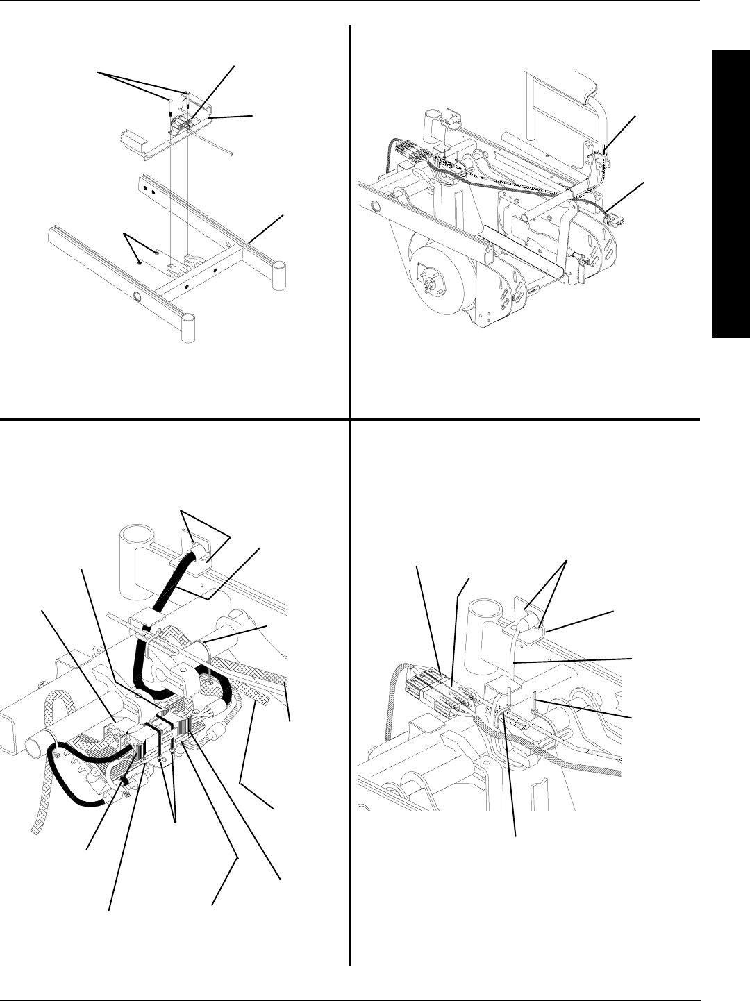
51
FRONT OF
CHAIR
REAR OF
CHAIR
Wiring Harness
Bracket
Mounting
Screws
Battery Box
Sub-Frame
Base
Frame
Locknuts
DETAIL A - GROUP 24 BATTERIES DETAIL B - GROUP 22 BATTERIES
DETAIL “C” -SECOND GENERATION
WHEELCHAIRS
Tie-Wraps
A and B
Wiring Harness
Connector
(BLUE)
Tie-Wrap
C
Controller
Connector
(BLUE)
Charger
Mount
Bracket
Wiring
Harness
Connector
(BLUE)
Controller
Connector
(BLUE)
DETAIL “D” - SECOND GENERATION
WHEELCHAIRS WITH GEARLESS /BRUSHLESS
MOTOR
Tie-Wrap
A
NOTE: There is no
need to cut this
tie-wrap.
NOTE: Illustration depicts gearless/brushless motor.
Wiring harness is secured to the rear of the seat frame
in the same manner for wheelchairs with conventional
motor/gearbox assembly.
NOTE: Battery box sub-frame exploded away for clari-
fication purposes only.
FIGURE 1 - REMOVING/INSTALLING THE WIRING HARNESS
W
I
R
I
N
G
H
A
R
N
E
S
S
Joystick
Cable
Wiring
Harness
Motor
Connector
Controller
Connector
Mounting
Screws
Battery
Charger
Cable
Motor
Connector
Cable
Wiring
Harness
Cable
Motor
Connector
Controller
Connector
Mounting
Screws
Charger
Cable
PROCEDURE 10WIRING HARNESS
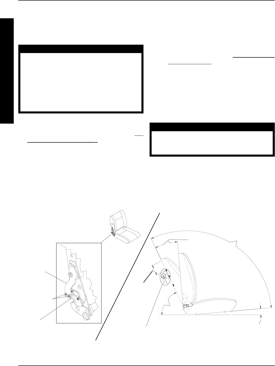
52
ADJUSTING LIMIT SWITCH
(FIGURE 2)
NOTE: The following procedure is for high back captains
van seat model wheelchairs only.
WARNING
NEVER operate the wheelchair while in any
recline position over 114o RELATIVE TO THE SEAT
FRAME. If the limit switch does not stop the
wheelchair from operating in a recline posi-
tion greater than 114o RELATIVE TO THE SEAT
FRAME, DO NOT operate the wheelchair. Ad-
just the limit switch BEFORE using the wheel-
chair, otherwise injury or damage can occur.
1. Place the wheelchair on a level surface.
2. Recline the captains van seat back to a 24o to achieve
the 114o angle relative to the seat frame. Refer to AD-
JUSTING CAPTAINS VAN SEAT in PROCEDURE 4 of
the owners manual, 1081227.
NOTE: The captains van seat frame is at a 5o angle relative
to the ground. When the back angle is adjusted to 114o rela-
tive to the seat, it will measure 61o relative to the ground.
NOTE: To determine 114o back angle relative to the seat
frame, place a magnetic protractor (available at any hard-
ware store) on the back as shown in FIGURE 2 and adjust
the back until the magnetic protractor reads 61o.
3. Turn the wheelchair power switch on the joystick to the
ON position.
NOTE: The wheelchair should not operate.
4. IF wheelchair operates, proceed to the following steps
to adjust the actuator on the upper limit switch bracket:
A. Fully recline the back. Refer to ADJUSTING CAP-
TAINS VAN SEAT in PROCEDURE 4 of the
Owners Manual, 1081227.
NOTE: This will make access to the limit switch easier.
B. Loosen, but do not remove, the two (2) phillips
screws, washers and locknuts that secure the ac-
tuator to the upper limit switch bracket.
C. Slide the actuator UP (towards the top of the wheel-
chair).
CAUTION
DO NOT over tighten the phillips screws that
secure the actuator to the upper limit switch
bracket. Damage to the actuator can occur.
D. Only tighten the two (2) phillips screws, washers
and locknuts that secure the actuator to the upper
limit switch bracket until the actuator does not move.
E. Repeat STEPS 1-3 until the wheelchair does not
operate when the captains van seat back is at a 24o
angle.
FIGURE 2 - ADJUSTING LIMIT SWITCH
24o Back
Recline Angle
61o
Magnetic Protractor - (Will read 61o when back
recline angle is at 114o relative to the seat frame)
Upper Limit
Switch
Bracket
Phillips
Screws,
Washers and
Locknuts
Actuator
5-3/4 inches
5o Seat Angle
114o
PROCEDURE 10 WIRING HARNESS
W
I
R
I
N
G
H
A
R
N
E
S
S

53
REPLACING BATTERY BOX
RETAINER BAR/RETAINER CLIP -
GROUP 24 BATTERY BASE FRAMES
(FIGURE 1)
1. Remove the battery box. Refer to INSTALLING/RE-
MOVING GROUP 24 BATTERY BOXES in PROCE-
DURE 9 of this manual.
Replacing Retainer Clip
1. Perform one (1) the following:
A. RWD AND MWD MODELS - Remove the
mounting screw that secures the retainer clip and
shock (or rubber element) to the base frame.
B. FWD MODEL - Remove the mounting screw,
washer, spacer, and locknut that secure the re-
tainer clip to the battery box sub-frame.
2. Remove the existing retainer clip.
3. Perform one (1) the following:
A. RWD AND MWD MODELS - Position the NEW
retainer clip between the shock (or rubber ele-
ment) and the battery box sub-frame as shown
in FIGURE 1. Make sure the angled end of the
retainer clip is facing up.
B. FWD MODEL - Position the NEW retainer clip
between the spacer and the battery box sub-
frame as shown in FIGURE 1. Make sure the
angled end of the retainer clip is facing upwards.
WARNING
The Battery Box Retainer Bar/Retainer Clip MUST
be fastened securely in place before using the
wheelchair. Use Loctite 242 and torque to 160-
inch pounds.
4. Perform one (1) the following:
A. RWD AND MWD MODELS -Reinstall the mount-
ing screw that secures the retainer clip and shock
(or rubber element) to the base frame. Use Loctite
242 and torque to 160-inch pounds.
RETENTION STRAP/RETAINER PROCEDURE 11
This Procedure Includes the Following:
Replacing Battery Box Retainer Bar/ Retainer Clip
-Group 24 Battery Base Frames
WARNING
After ANY adjustments, repair or service and BE-
FORE use, make sure that all attaching hardware
is tightened securely - otherwise injury or dam-
age may result.
R
E
T
E
N
T
I
O
N
S
T
R
A
P
R
E
T
A
I
N
E
R
B. FWD MODEL - Reinstall the mounting screw,
washer, spacer, and locknut that secure the retainer
clip to the battery box sub-frame. Use Loctite 242
and torque to 160-inch pounds.
5. Reinstall the battery boxes. Refer to INSTALLING/RE-
MOVING BATTERY BOXES - GROUP 24 BATTERY
BASE FRAMES in PROCEDURE 9 of this manual.
Replacing Retainer Bar
1. Perform one (1) the following:
A. RWD AND MWD MODELS -Remove the two (2)
mounting screws and spacers that secure the bat-
tery box retainer bar to the base frame.
B. FWD MODELS - Remove the two (2) mounting
screws, spacers, washers, and locknuts that se-
cure the retainer bar to the battery box sub-frame.
2. Pull up on the battery box retainer bar to remove it from
the base frame.
3. Install the two (2) existing spacers through the mounting
holes in the NEW battery box retainer bar.
WARNING
The Battery Box Retainer Bar/Retainer Clip MUST be
fastened securely in place before using the wheel-
chair. Use Loctite 242 and torque to 160-inch
pounds.
4. Perform one (1) the following:
A. RWD AND MWD MODELS - Line up the NEW
battery box retainer bar and spacers with the mount-
ing holes in the battery box sub frame and the base
frame.
B. FWD MODELS - Line up the NEW battery box
retainer bar and spacers with the mounting holes in
the battery box sub frame.
5. Perform one (1) the following:
A. RWD AND MWD MODELS - Reinstall the mount-
ing screws that secure the battery box retainer bar
between battery box sub frame and the base frame.
Use Loctite 242 and torque to 160-inch pounds.
B. FWD MODELS - Reinstall the mounting screws
that secure the battery box retainer bar onto battery
box sub frame. Use Loctite 242 and torque to 160-
inch pounds.
6. Reinstall the both battery boxes. Refer to INSTALLING/
REMOVING GROUP 24 BATTERY BOXES in PRO-
CEDURE 9 of this manual.
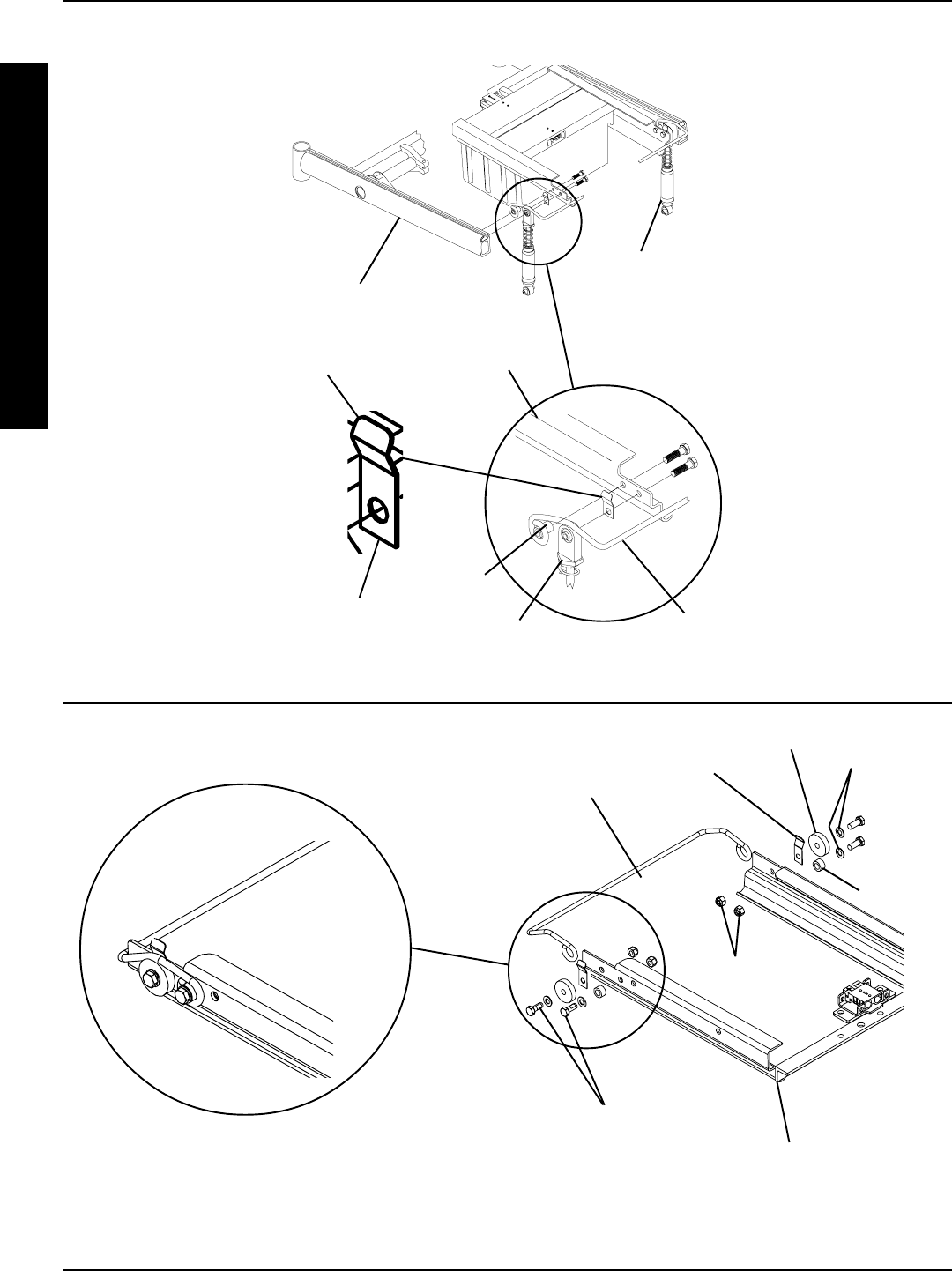
54
PROCEDURE 12 WHEELS/MOTORS
Retainer
Clip
Mounting
Screws
Battery Box
Sub-frame
Base Frame
Angled End
(Facing Upward)
Retainer
Bar
Shock
Assembly
Top of Shock
Assembly
Spacer
RWD AND MWD MODELS
FWD MODELS
Retainer Bar
Mounting Screws
Washers
Spacer
Retainer
Clip
Spacer
Locknuts
Battery Box
Sub-Frame
ASSEMBLED VIEW
W
H
E
E
L
S
/
M
O
T
O
R
S
FIGURE 1 - REPLACING BATTERY BOX RETAINER BAR/RETAINER CLIP - GROUP 24 BATTERY BASE FRAMES
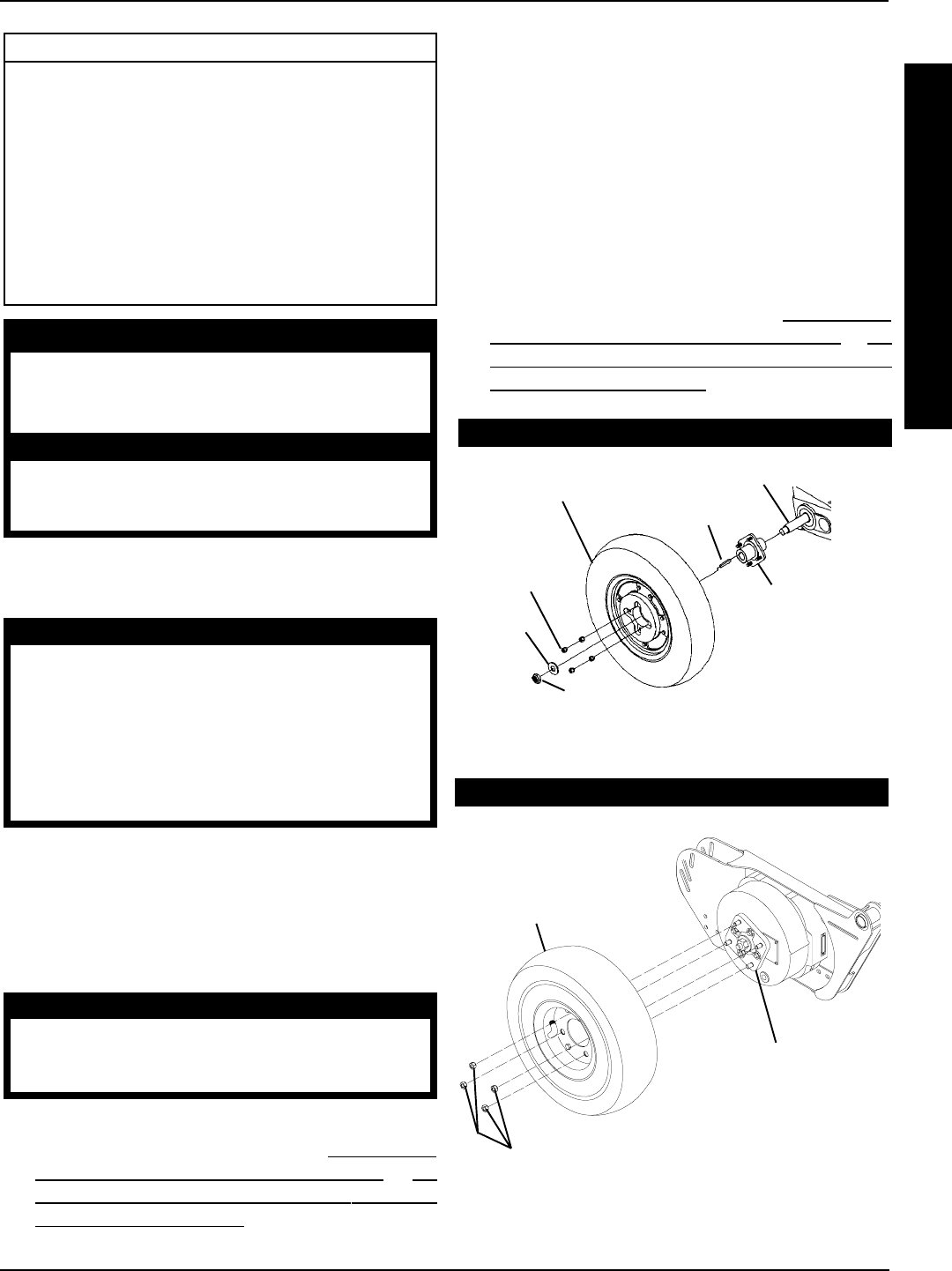
55
W
H
E
E
L
S
/
M
O
T
O
R
S
This Procedure includes the following:
Replacing Pneumatic Tires/Tubes - Drive Wheels/
Casters
Removing/Installing Drive Wheels
Removing/Installing Drive Wheel Hub
Installing Wheel Lock Bracket onto Wheelchair
Removing/Installing Casters
Replacing Forks
Motor Replacement
WARNING
After ANY adjustments, repair or service and BEFORE
use, make sure all attaching hardware is tightened
securely - otherwise injury or damage may result.
CAUTION
As with any vehicle, the wheels and tires should
be checked periodically for cracks and wear
and should be replaced. Keystock
*Locknut
*Washer
Four (4)
Beveled
Hex Nuts
Drive Wheel Assembly
Wheel Hub
Assembly
Gearbox Drive Shaft
FIGURE 1 - REMOVING/INSTALLING DRIVE WHEELS
2. Remove the four (4) beveled hex nuts that secure the
drive wheel assembly to the wheel hub assembly.
3. Remove existing drive wheel assembly from wheel hub.
Installing
1. Reinstall new/existing drive wheel assembly to the
wheel hub assembly and torque the four (4) beveled
hex nuts to 160-inch pounds.
2. Repeat procedure for opposite side of wheelchair, if
necessary.
3. Reinstall the battery box(es). Refer to INSTALLING/
REMOVING GROUP 24 BATTERY BOXES or IN-
STALLING/REMOVING GROUP 22 BATTERY
BOXES in PROCEDURE 9 of this manual.
CONVENTIONAL MOTOR WITH GEARBOX
GEARLESS/BRUSHLESS MOTOR
REPLACING PNEUMATIC TIRES/
TUBES - DRIVE WHEELS/CASTERS
WARNING
DO NOT use your wheelchair unless it has the
proper tire pressure (p.s.i.). DO NOT overinflate the
tires. Failure to follow these suggestions may cause
the tire to explode and cause bodily harm.
If tires are pneumatic, replacement of tire or tube
MUST be performed by an authorized Invacare
dealer or qualified technician.
NOTE: If drive wheels or casters are pneumatic, under-in-
flation causes excessive wear which results in poor perfor-
mance of the tires.
REMOVING/INSTALLING DRIVE
WHEELS (FIGURE 1)
CAUTION
Perform the following procedure in a designated
work area to prevent damage to flooring (car-
peting, tile, etc.).
Removing
1. Remove the battery box(es). Refer to INSTALLING/
REMOVING GROUP 24 BATTERY BOXES or IN-
STALLING/REMOVING GROUP 22 BATTERY
BOXES in PROCEDURE 9 of this manual.
Four (4) Beveled Hex Nuts
Drive Wheel
Assembly
Wheel Hub
Assembly
*NOTE: It is not required to remove the locknut and
washer to remove the drive wheel.
PROCEDURE 12WHEELS/ MOTORS
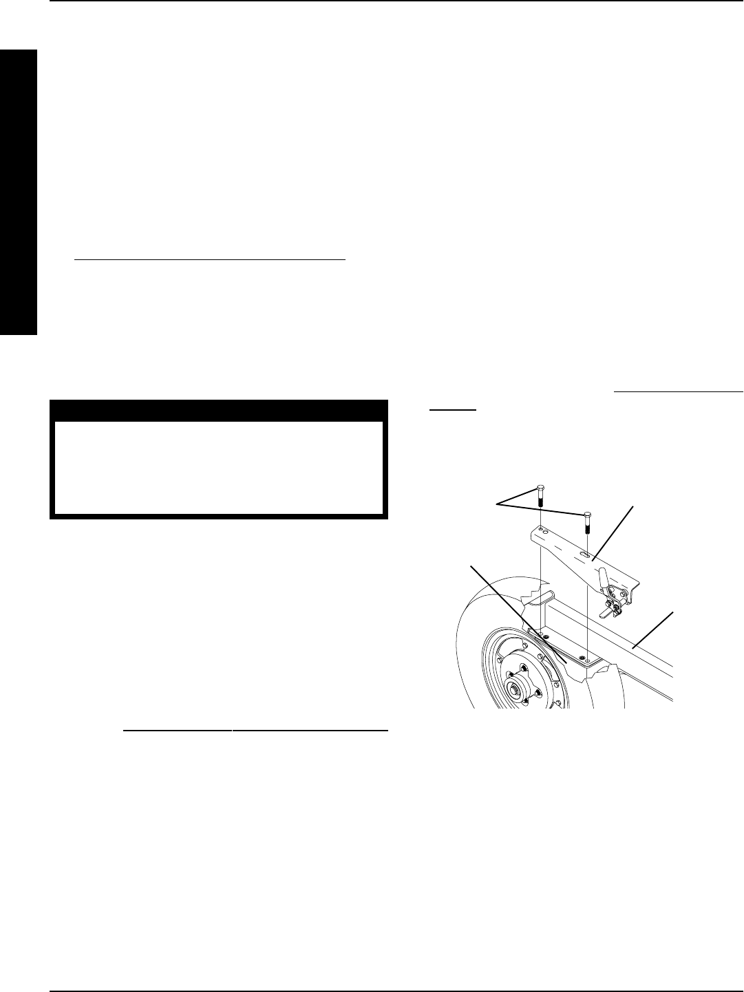
56
PROCEDURE 12 WHEELS/MOTORS
REMOVING/INSTALLING DRIVE
WHEEL HUB (FIGURE 1)
NOTE: This procedure can only be performed on sec-
ond generation storm wheelchairs with the conven-
tional motor/gearbox assembly. On second genera-
tion storm wheelchairs with the gearless/brushless
motor, the drive wheel hub CANNOT be removed.
Return motor to manufacturer for service.
Removing
1. Remove the drive wheel from the wheelchair. Refer to
REMOVING/INSTALLING DRIVE WHEELS in this
procedure of the manual.
2. Remove the locknut, washer, keystock and existing
drive wheel hub from the drive shaft of the gearbox.
Installing
1. Position the keystock on the gearbox drive shaft.
CAUTION
DO NOT apply more than a one (1)-inch (in length)
thin film of anti-seize compound to the drive shaft.
Applying more than one (1)-inch (in length) can
cause the anti-seize compound to leak resulting
in damage to flooring (carpet, tile, etc.).
2. Apply a thin film of anti-seize compound one (1) inch in
length to the end of the drive shaft.
3. Reinstall drive wheel hub onto the gearbox drive shaft.
NOTE: While installing the drive wheel hub onto the drive
shaft, spin the drive wheel hub to evenly distribute the anti-
seize compound over the entire drive shaft.
4. Reinstall the washer and locknut and torque locknut to
45 foot pounds (540-inch pounds).
5. Reinstall the drive wheel assembly to the wheelchair.
Refer to REMOVING/INSTALLING DRIVE WHEELS
in this procedure of the manual.
6. Repeat procedure for the opposite side of the wheel-
chair, if necessary.
Gearbox
Wheel Lock
Mounting
Bracket
Mounting
Screws
FIGURE 2 - INSTALLING WHEEL LOCK BRACKET
ONTO WHEELCHAIR
Suspension
Arm
INSTALLING WHEEL LOCK BRACKET
ONTO WHEELCHAIR (FIGURE 2)
NOTE: This procedure only pertains to second gen-
eration storm wheelchairs with the conventional mo-
tor and gearbox. On second generation storm wheel-
chairs with the gearless/brushless motor, the wheel
lock bracket is not required.
1. Remove the two (2) mounting screws closest to the large
wheel that secure the gearbox to the suspension arm.
2. Line up mounting holes in the wheel lock mounting bracket
with the gearbox mounting holes in the suspension arm.
3. Apply Loctite 242 to the two (2) mounting screws.
4. Reinstall the two (2) mounting screws into the mounting
holes of the wheel lock mounting bracket and gear box
and torque to 75-inch pounds.
5. Repeat STEPS 1-4 for opposite wheel lock bracket.
6. Adjust the wheel locks. Refer to ADJUSTING WHEEL
LOCKS in PROCEDURE 9 of the owners manual,
1081227.
W
H
E
E
L
S
/
M
O
T
O
R
S
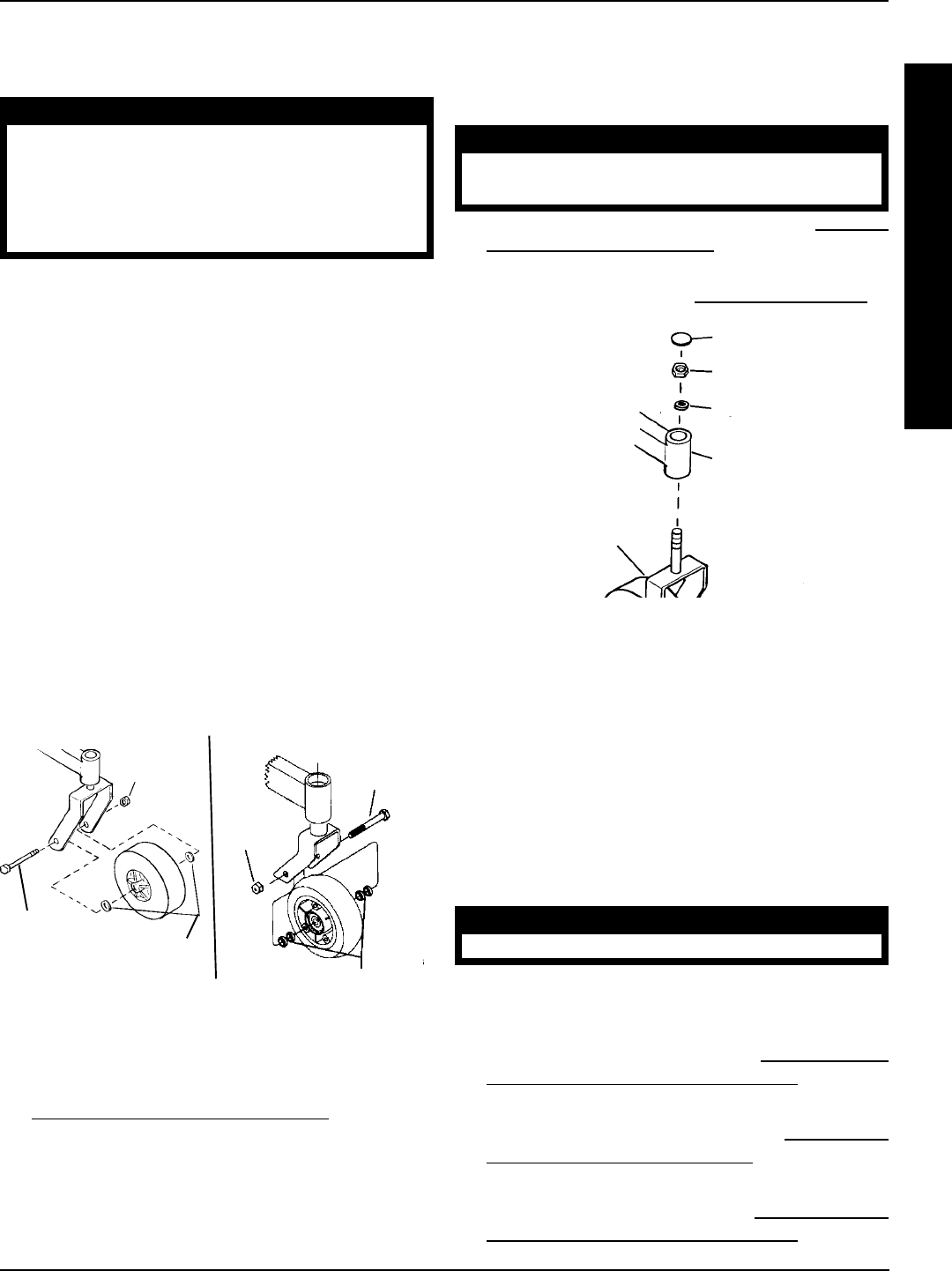
57
REMOVING/INSTALLING THE
MOTOR (CONVENTIONAL MOTOR
WITH GEARBOX) (FIGURE 5)
Removing
RWD AND MWD MODELS.
1. Disconnect the right and/or left motor connector from
the controller.
2. Remove the two (2) allen screws and washers that
secure the motor to the gearbox.
CAUTION
DO NOT damage the motor/gearbox coupling.
3. Carefully pull the motor away from the gearbox.
ARROW FWD MODEL.
1. Remove the front shroud. Refer to REMOVING/IN-
STALLING SIDE SHROUD ASSEMBLY in PROCE-
DURE 17 of this manual.
2. Remove the counterweight. Refer to REMOVING/
INSTALLING COUNTERWEIGHT in PROCEDURE
17 of this manual.
3. Remove the battery box(es). Refer to INSTALLING/RE-
MOVING GROUP 24 BATTERY BOXES in PROCE-
DURE 9 of this manual.
REMOVING/INSTALLING CASTERS
(FIGURE 3)
WARNING
DO NOT use your power wheelchair unless it has
the proper tire pressure (p.s.i.). DO NOT over-inflate
the tires. Failure to follow these suggestions may
cause the tire to explode and cause bodily harm.
The recommended tire pressure is listed on the side
wall of the tire.
Periodically, the tires will need to be replaced due to wear or
puncture.
Removing Casters
1. Remove the mounting screw, spacers and locknut that
secure the existing caster to the fork.
2. Remove the existing caster from the fork.
Installing Casters
1. Position the new/existing caster into the fork.
2. Reinstall the mounting screw, spacers and locknut that
secure the caster to the fork.
3. Torque locknut to 10-foot pounds (120-inch) pounds.
4. Loosen the locknut 1/8 of a turn.
5. Move the caster side to side.
NOTE: If the caster moves side to side, tighten the locknut
slightly. Repeat STEP 4 until there is no side to side move-
ment of the caster.
Mounting
Screw
Locknut
Mounting
Screw
Locknut
6-INCH 8-INCH
Spacers
FIGURE 3 - REMOVING/INSTALLING CASTERS
Spacers
REPLACING FORKS (FIGURE 4)
1. Remove the caster from the existing fork. Refer to
REMOVING/INSTALLING CASTERS in this proce-
dure of the manual.
2. Remove the head tube cap.
3. Remove the locknut and nylon washer.
4. Drop the existing fork out of the caster head tube.
5. Slide the new fork into the caster head tube.
NOTE: Check bearing assemblies. Replace if necessary.
6. Ensure new fork slides completely into caster headtube.
7. Install nylon washer and secure with locknut.
WARNING
Improper positioning of the washer will prohibit the
free movement of the forks.
8. Install the caster onto the new fork. Refer to REMOV-
ING/INSTALLING CASTERS in this procedure of the
manual.
9. Adjust the forks. Refer to ADJUSTING FORKS in
PROCEDURE 9 of the owners manual, 1081227
FIGURE 4 - REPLACING FORKS
Dust Cover
Locknut
Nylon Washer
Caster Headtube
Fork
W
H
E
E
L
S
/
M
O
T
O
R
S
WHEELS/MOTORS PROCEDURE 12
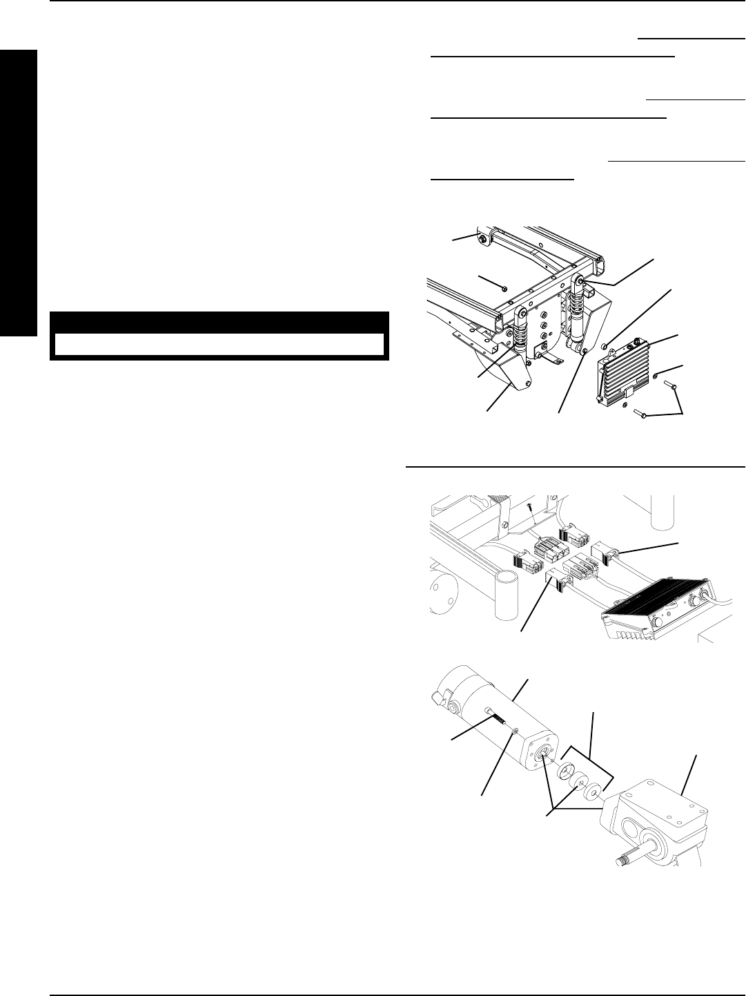
58
PROCEDURE 12 WHEELS/MOTORS
W
H
E
E
L
S
/
M
O
T
O
R
S
4. Remove the two (2) mounting screws, spacers, and
washers that secure the MKIV controller to the base
frame. Set MKIV controller onto ground/floor.
NOTE: STEPS 5, 6, and 7 are necessary to obtain
easier access to the motor/controller connection.
5. Remove the mounting screw and spacer that secure
the top of the shock to the base frame.
6. Loosen, DO NOT remove, the mounting screw that se-
cures the bottom of the shock to the suspension arm.
7. Rotate top of shock toward the inside of the wheelchair.
]
8. Disconnect the motor connector from controller.
9. Remove the two (2) allen screws and washers that
secure the motor to the gearbox.
CAUTION
DO NOT damage the motor/gearbox coupling.
10. Carefully pull the motor away from the gearbox.
Installing
1. Perform one (1) of the following:
A. For RWD and MWD perform STEPS 2-3.
B. For FWD ONLY perform STEPS 2-10.
2. Perform the following:
A. Inspect the coupling for wear and damage. If dam-
age is evident, replace coupling.
B. Install coupling onto gearbox input shaft inserting cou-
pling drive plate onto slot on shaft.
C. Carefully align motor and coupling and place motor
against gearbox.
D. With motor against gearbox, turn gearbox drive shaft
until the coupler seats into gearbox.
NOTE: When properly aligned, motor will be seated into
gearbox.
E. Install two (2) allen screws. Use Loctite 242, tighten
allen screws evenly and then torque to 75-inch lbs.
3. Reconnect right and/or left motor connector to controller.
4. Rotate the top of the shock of the shock toward the inside
of the wheelchair.
5. Install the mounting screw and spacer that secure the top
of the shock to the base frame. Torque to 156 - inch
pounds.
6. Tighten the mounting screw that secures the bottom of
the shock to the suspension arm. Torque to 156 - inch
pounds.
7. Install the two mounting screws that secure the MKIV
controller to the base frame. Torque to 156 - inch pounds.
FIGURE 5 - REMOVING/INSTALLING THE MOTOR -
CONVENTIONAL MOTOR/GEARBOX FOR RWD,
MWD AND FWD MODELS
Slots*
*NOTE: The following slot locations must line up for proper
installation: Slots on coupling of motor, the slots on the
coupling and the slots on the gearbox.
Gearbox
Motor
Allen
Screw
Washer
Coupling
Motor Connector
Motor
Connector
8. Install the battery box(es). Refer to INSTALLING/RE-
MOVING GROUP 24 BATTERY BOXES in PROCE-
DURE 9 of this manual.
9. Install the counterweight. Refer to REMOVING/IN-
STALLING THE COUNTERWEIGHT in PROCE-
DURE 17 of this manual.
10. Install the front shroud. Refer to REMOVING/INSTALL-
ING FRONT SHROUD in PROCEDURE 17 of this
manual. ARROW FWD MODEL ONLY
RWD, MWD, AND ARROW FWD MODELS
Base
Frame
MKIV
Controller
Mounting
Screws
Washer
Shock
Suspension
Arm
Mounting Screw
(REMOVE)
Mounting Screw
(Loosen, DO NOT
REMOVE)
Locknut Spacer

59
3. Secure motor to the suspension arm with existing
four (4) mounting screws. Torque to 13 foot/pounds.
4. Slide the motor lock lever along brake release shaft
until the end is flush with the bushing guide.
5. Slide alignment pin, located inside of bushing guide,
into the end of the motor lock lever and secure in
place with existing mounting screw and washer. Se-
curely tighten.
6. Secure motor lock lever in place on the brake re-
lease shaft with existing mounting screw.
7. Install the drive wheel from the wheelchair. Refer to
REMOVING/INSTALLING DRIVE WHEELS in this
procedure of the manual.
8. If necessary, install the group 22 battery box tray. Re-
fer to REMOVING/INSTALLING GROUP 22 BAT-
TERY BOX TRAY in PROCEDURE 16 of this
manual.
9. Plug the wiring harness connector into the motor.
10. Secure the wiring harness connector to the motor
with the existing two (2) mounting screws.
11. Remove the battery box(es). Refer to INSTALLING/
REMOVING GROUP 24 BATTERY BOXES or IN-
STALLING/REMOVING GROUP 22 BATTERY
BOXES in PROCEDURE 9 of this manual.
REMOVING/INSTALLING THE
MOTOR (GEARLESS/BRUSHLESS
MOTOR) (FIGURE 6)
Removing
1. Remove the battery box(es). Refer to INSTALLING/
REMOVING GROUP 24 BATTERY BOXES or IN-
STALLING/REMOVING GROUP 22 BATTERY
BOXES in PROCEDURE 9 of this manual.
2. Unthread the mounting screws that secure the wiring
harness connector to the motor (DETAIL A).
3. Unplug the wiring harness connector from the motor.
4. If necessary, remove the group 22 battery box tray.
Refer to REMOVING/INSTALLING GROUP 22 BAT-
TERY BOX TRAY in PROCEDURE 16 of this
manual.
5. Remove the drive wheel from the wheelchair. Refer to
REMOVING/INSTALLING DRIVE WHEELS in this
procedure of the manual.
6. Note the mounting position of the motor on the sus-
pension arm before removing the motor.
7. Loosen adjustment screw that secures the motor lock
lever in place on the brake release shaft.
NOTE: Alignment pin is located inside of bushing guide
on the suspension arm.
8. Remove the mounting screw and washer that se-
cure the alignment pin in place.
9. Slide the alignment pin back out of the end of the
motor lock lever.
10. Remove the four (4) mounting screws and washers
that secure the motor to the suspension arm.
11. Remove motor with motor lock lever from suspen-
sion arm.
12. If replacing motor, remove the motor lock lever from
the brake release shaft of the existing motor.
Installing
NOTE: Do not tighten adjustment screw of motor lock le-
ver until motor is secured in place on the suspension arm.
1. If necessary, install motor lock lever onto new brake
release shaft of motor.
2. Position the new/existing motor with motor lock lever
onto the suspension arm in the mounting position
noted from STEP 4 of REMOVING THE GEARLESS/
BRUSHLESS MOTOR in this procedure of the
manual.
W
H
E
E
L
S
/
M
O
T
O
R
S
PROCEDURE 12WHEELS/MOTORS

60
Mounting Screw
Washer
Mounting
Screws
Mounting Screws
Washer
Motor
Suspension
Arm
Motor Lock
Lever
Adjustment
Screw
Mounting
Screw
Washer
*Alignment Pin
*NOTE: Alignment pin exploded away suspension arm for clarification purposes only.
Brake Release Shaft
Guide
Bushing
PROCEDURE 12 WHEELS/MOTORS
W
H
E
E
L
S
/
M
O
T
O
R
S
Mounting
Screws
DETAIL “A”
Wiring Harness
Connector
Motor
FIGURE 2 - REMOVING/INSTALLING MOTOR - GEARLESS/BRUSHLESS
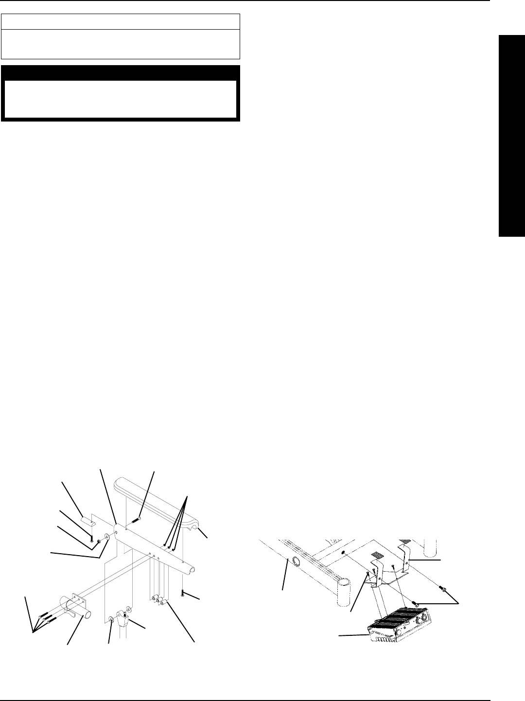
61
FIGURE 2 - REMOVING/INSTALLING MKIV
CONTROLLER
Mounting
Plate
Mounting Screws
Hex
Bolts
MKIV Controller
Base Frame
NOTE: Controller for gearless/brushless motor re-
moves in the same manner.
FIGURE 1 - REPOSITIONING MKIV JOYSTICK -
VAN SEAT MODELS
Locknuts
(STEPS 3,16)
Phillips
Screws
(STEPS 4,
14)
Lug Bolt (STEPS 7, 9)
Joystick Mounting
Bracket (STEPS 3, 16)
Hex Bolts
(STEPS 3, 16)
Spacers
(STEPS 3, 16)
Armrest Insert
Phillips Screw
(STEPS 5, 13)
Armrest
Pad
Armrest Plate
Washer
(STEPS 7, 9)
Locknut
(STEPS 7, 9)
Washers
(STEPS 7, 9)
11. Position the armrest pad on the armrest plate.
12. Line up the mounting holes in the armrest insert, arm-
rest plate and armrest pad.
13. Reinstall rear phillips screw through the armrest insert,
armrest plate and armrest pad and tighten securely.
14. Reinstall the front phillips screw into the armrest plate
and new armrest pad and tighten securely.
15. Repeat STEPS 11-14 for opposite side of wheelchair.
16. Install the three (3) hex bolts, spacers and locknuts
that secure the joystick mounting bracket to the arm-
rest plate.
17. Slide the joystick mounting tube through the joystick
mounting bracket to the desired position.
18. Secure the adjustment lock to the joystick mounting
tube by turning the lever on the adjustment lock.
REMOVING/INSTALLING MKIV
CONTROLLER (FIGURE 2)
RWD and MWD Models
REMOVING.
1. Remove the shroud that covers the MKIV controller.
2. Disconnect the left/right motor leads and battery leads.
3. Remove the two (2) hex bolts that secure the existing
MKIV controller to the wheelchair.
4. Remove existing MKIV controller from the wheelchair.
5. Remove the three (3) mounting screws that secure
the mounting plate to the MKIV controller.
INSTALLING.
1. Install the three (3) mounting screws into the mounting
plate and secure to the MKIV controller.
2. Secure the new/existing MKIV controller to the wheel-
chair with two (2) hex bolts.
3. Connect the left/right motor leads and battery leads
4. Install shroud over the MKIV controller.
Armrest
Weldment
E
L
E
C
T
R
O
N
I
C
S
PROCEDURE 13ELECTRONICS
This Procedure Includes the Following:
Repositioning MKIV Joystick - Van Seat Models
Removing/Installing MKIV Controller
WARNING
After ANY adjustments, repair or service and BEFORE
use, make sure that all attaching hardware is tightened
securely - otherwise injury or damage may result.
REPOSITIONING MKIV JOYSTICK -
VAN SEAT MODELS (FIGURE 1)
1. Turn the lever on the adjustment lock to release the
adjustment lock from joystick mounting tube.
2. Remove the joystick mounting tube from wheelchair.
3. Remove the three (3) hex bolts, spacers and locknuts
that secure joystick mounting bracket to armrest plate.
4. Remove the phillips screws that secures the front of the
armrest pad to the armrest plate.
5. Remove the phillips screw that secures the rear of the
armrest pad and armrest insert to the armrest plate.
6. Remove the armrest pad from the armrest plate.
7. Remove the lug bolt, washers and locknut that secure
the existing armrest plate to the armrest weldment.
8. Repeat STEPS 4-7 for opposite side of the wheelchair.
9. Position armrest plate with joystick mounting holes on
desired side of armrest weldment and secure with lug
bolt, washers and locknut. Refer to FIGURE 1 for cor-
rect hardware orientation.
10. Position armrest plate without joystick mounting holes
on opposite side of the armrest weldment and secure
with lug bolt, washers and locknut. Refer to FIGURE
1 for correct hardware orientation.
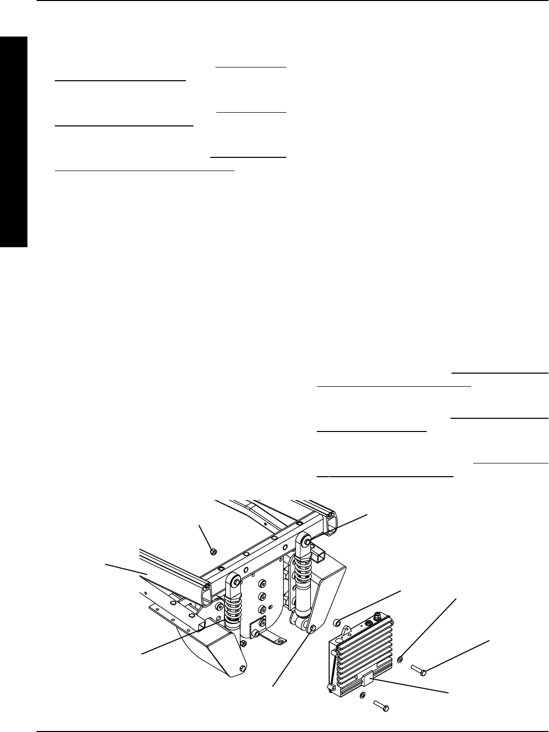
62
Arrow Fwd Model
REMOVING.
1. Remove the front shroud. Refer to REMOVING/IN-
STALLING FRONT SHROUD in PROCEDURE 17 of
this manual.
2. Remove the counterweight. Refer to REMOVING/IN-
STALLING COUNTERWEIGHT in PROCEDURE 17
of this manual.
3. Remove the battery box(es). Refer to INSTALLING/RE-
MOVING GROUP 24 BATTERY BOXES in PROCE-
DURE 9 of this manual.
4. Disconnect the joystick cable from the top of the control-
ler.
5. Disconnect the battery wiring harness and controller con-
nection.
6. Remove the two (2) mounting screws, spacers, wash-
ers, and locknuts that secure the MKIV controller to the
base frame. Set MKIV controller onto ground/floor.
7. Remove the mounting screw and spacer that secure the
top of right shock to the base frame.
8. Loosen, DO NOT remove, the mounting screw that se-
cure the bottom of the right shock to the suspension arm.
9. Rotate top of right shock toward inside of the wheelchair.
10. Disconnect right hand motor/controller connection.
11. Rotate top of right shock back into position.
12. Loosely install mounting screw through top of shock and
into base frame. DO NOT tighten at this point.
13. To disconnect left hand motor/controller connection, per-
form STEPS 5-8 for opposite side of controller.
INSTALLING.
1. Connect left hand motor/controller connection of NEW
controller.
2. Rotate top of left shock into position.
3. Secure top of left shock to base frame with washer and
mounting screw. Torque to 360 - inch pounds.
4. Remove mounting screw and washer that secure the top
of the right shock to the base frame.
5. Rotate shock toward inside of wheelchair.
6. Connect right hand motor/controller connection.
7. Rotate shock back into position.
8. Secure top of right shock to base frame with washer and
mounting screw. Torque to 156 - inch pounds.
9. Torque the bottom mounting screw of each shock to 160
- inch pounds.
10. Secure the MKIV controller to the base frame with the
two (2) existing mounting screws, spacers, washers, and
locknuts.
11. Connect the joystick cable to the top of the controller.
12. Connect the battery wiring harness and controller con-
nection.
13. Install the battery box(es). Refer to INSTALLING/REMOV-
ING GROUP 24 BATTERY BOXES in PROCEDURE
9 of this manual.
14. Install the counterweight. Refer to REMOVING/INSTALL-
ING COUNTERWEIGHT in PROCEDURE 17 of this
manual.
15. Install the front shroud. Refer to REMOVING/IN-
STALLING FRONT SHROUD in PROCEDURE 17
of this manual.
FIGURE 2 - REMOVING/INSTALLING MKIV CONTROLLER - ARROW FWD MODEL
Mounting
Screw
Washer
Controller
Spacer
Locknut
Base Frame
Shock
Top Mounting
Screw and
Washer
Bottom Mounting
Screw
PROCEDURE 13 ELECTRONICS
E
L
E
C
T
R
O
N
I
C
S
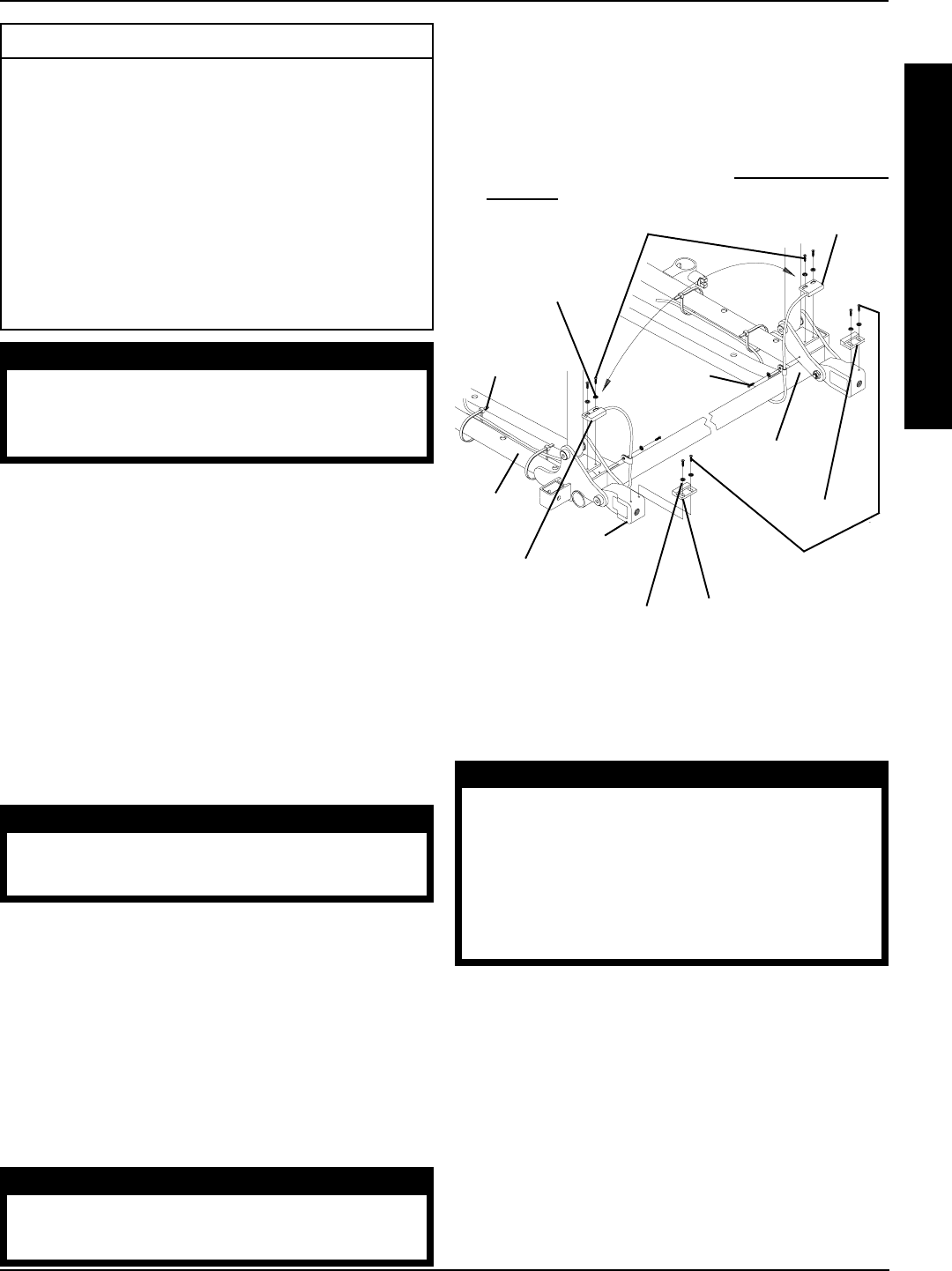
63
Mounting
Screws
Mounting Screws
(DO NOT
Overtighten)
Actuator
Tie
Wraps
Wire
Retainer
Limit
Switch
Sensor
Seat
Frame
Mounting Screws (DO
NOT Over Tighten)
Washers
Limit Switch Sensor
FIGURE 1 - POSITIONING LIMIT SWITCH
Gas Cylinder
Pivot Block
Actuator
Washers
POSITIONING LIMIT SWITCH
(FIGURE 1)
NOTE: The battery charger connector, as well as, the limit
switch are factory set on the RIGHT side of the wheelchair.
However, they can be positioned on either side for user
convenience. The limit switch MUST BE positioned on the
same side as the battery charger connector.
1. Cut the two (2) tie wraps that secure the limit switch
wire to the seat frame.
2. Remove the two (2) mounting screws and washers
that secure the actuator to the gas cylinder pivot block.
3. Position actuator on opposite gas cylinder pivot block.
CAUTION
DO NOT over tighten the mounting screws that se-
cure the actuator to the pivot block. Damage to
actuator will occur.
4. Secure the actuator to the pivot block with the two (2)
mounting screws and washers. DO NOT overtighten.
5. Remove the mounting screw that secures the wire
retainer to the inside of the seat frame.
6. Remove the two (2) mounting screws and washers
that secure the limit switch sensor to the seat frame.
7. Turn limit switch sensor over so opposite side is facing
up and the wire is on the INSIDE of the seat frame.
8. Position the limit switch sensor onto the opposite side
of the seat frame.
CAUTION
DO NOT over tighten the mounting screws that
secure the limit switch sensor to the seat frame.
Damage to the limit switch sensor will occur.
This Procedure Includes the Following:
Positioning Limit Switch
Adjusting Limit Switch
Replacing Recliner Cable Assemblies
Replacing/Adjusting Gas Cylinders
Changing Back Height
Changing Seat Depth
Changing Seat Width
Installing/Replacing Adjustable 16 to 19-inch Deep
Recliner Seat Frame onto Arrow or X Base
WARNING
After ANY adjustments, repair or service and BEFORE
use, make sure that all attaching hardware is tight-
ened securely - otherwise injury or damage may
result.
PROCEDURE 14RECLINER
9. Secure limit switch sensor to the seat frame with the
two (2) mounting screws and washers.
10. Secure the wire retainer onto the INSIDE of the seat
frame with the mounting screw.
11. Tie wrap the limit switch wire to the seat frame.
12. Adjust the limit switch. Refer to ADJUSTING LIMIT
SWITCH in this procedure of the manual.
ADJUSTING LIMIT SWITCH
(FIGURE 2)
WARNING
NEVER operate the wheelchair while in any re-
cline position over 105o RELATIVE TO THE SEAT
FRAME. If the limit switch does not stop the wheel-
chair from operating in a recline position greater
than 105o RELATIVE TO THE SEAT FRAME, do not
operate the wheelchair. Adjust the limit switch
BEFORE using the wheelchair, otherwise injury
or damage can occur.
1. Recline the back of the wheelchair until the gas cylin-
der rod measures 3-21/32 of an inch.
2. Turn the power of the joystick to the ON position.
NOTE: ALL segments of the bar graph on the joystick should
start to flash on and off and the wheelchair should not op-
erate.
3. IF the wheelchair operates, proceed to the following
steps to adjust the actuator on the gas cylinder pivot
block:
A. Loosen, but do not remove, the two (2) mounting
screws and washers that secure the actuator to
the gas cylinder pivot block.
R
E
C
L
I
N
E
R
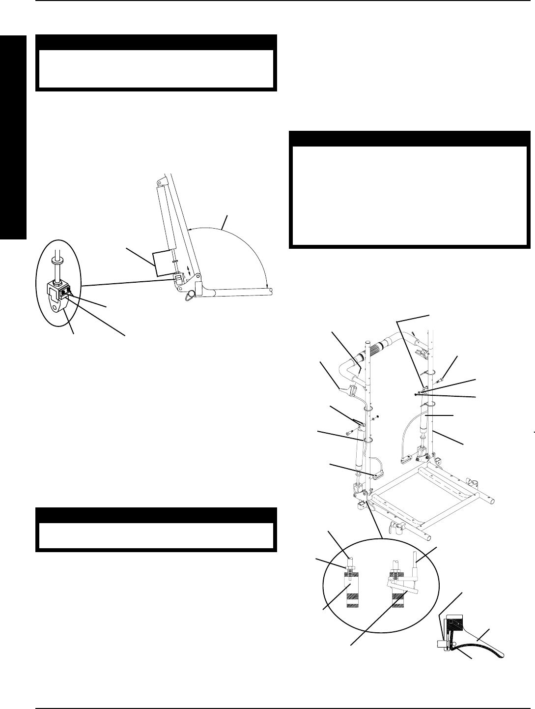
64
PROCEDURE 14 RECLINER
FIGURE 2 - ADJUSTING LIMIT SWITCH
R
E
C
L
I
N
E
R
Mounting Screws and Washers
(DO NOT Over-Tighten)
Actuator
Gas Cylinder
Rod Measures
3-21/32-inches
POSITION OVER
105O RELATIVE TO
THE SEAT FRAME
Gas Cylinder
Pivot Block
6. Remove the operator of the existing recliner cable
assembly from the pivot block.
7. Make sure the threads of the gas cylinder rod are
flush with the inside of the pivot block.
8. With the operator of the NEW recliner cable assem-
bly on the inside of the recliner seat frame, line up the
mounting hole in the operator of the new recliner cable
assembly with the gas cylinder rod.
CAUTION
DO NOT force the gas cylinder rod into the op-
erator of the recliner cable assembly.
DO NOT cross thread the operator of the recliner
cable assembly with the gas cylinder.
If slack in the recliner cable or movement in the
operator of the cable assembly can not be elimi-
nated, DO NOT use the recliner cable assembly.
9. Screw the NEW gas cylinder into the operator of the
cable assembly until the jam nut sits on the pivot block,
there is no slack in the recliner cable and there is no
movement in the operator of the recliner cable as-
sembly.
B. Slide actuator UP (towards top of the wheelchair).
CAUTION
DO NOT over tighten the mounting screws that
secure the actuator to the pivot block. Damage
to the actuator will occur.
C. Only tighten the two (2) mounting screws and
washers that secure the actuator to the gas cylin-
der pivot block until the actuator does not move.
D. Repeat STEPS 1 and 2 until the wheelchair does
not operate when the gas cylinder rod is 3-21/32-
inch long.
REPLACING RECLINER CABLE
ASSEMBLIES (FIGURE 3)
NOTE: There are three (3) different cable lengths de-
pending on back height:
CABLE LENGTH BACK HEIGHT
Short 18-1/2 and 20-inches
Medium 22 and 24-inches
Long 26-inches
WARNING
Replace ONE (1) recliner cable assembly at a
time to avoid injury.
1. Cut the tie wraps that secure the existing recliner cable
assembly to the back cane.
2. Remove the pan screw that secures the handle of
the existing recliner cable assembly to the back cane.
3. Loosen the jam nut on the gas cylinder rod.
4. Remove the mounting screw, washer, nylon wash-
ers and locknut that secure the TOP of the gas cylin-
der to the mounting bracket on the back cane.
5. Unscrew the gas cylinder from the operator of the
existing recliner cable assembly but do not remove
the gas cylinder from the pivot block. FIGURE 3 - REPLACING RECLINER CABLE ASSEMBLIES
Jam
Nut
Washer
Handle
Nylon
Washers
Pivot
Block
Locknut
Back Cane
Gas Cylinder
Gas Cylinder
Rod
Mounting Screw
Pan Screw
No Slack
in Cable
NO Movement in Operator
of the Recliner Cable
Assembly
Cable Fitting
Seated Properly
Handle
Cable
Snapped
into Slot
Cable
Operator
Tie
Wraps
Mounting Bracket
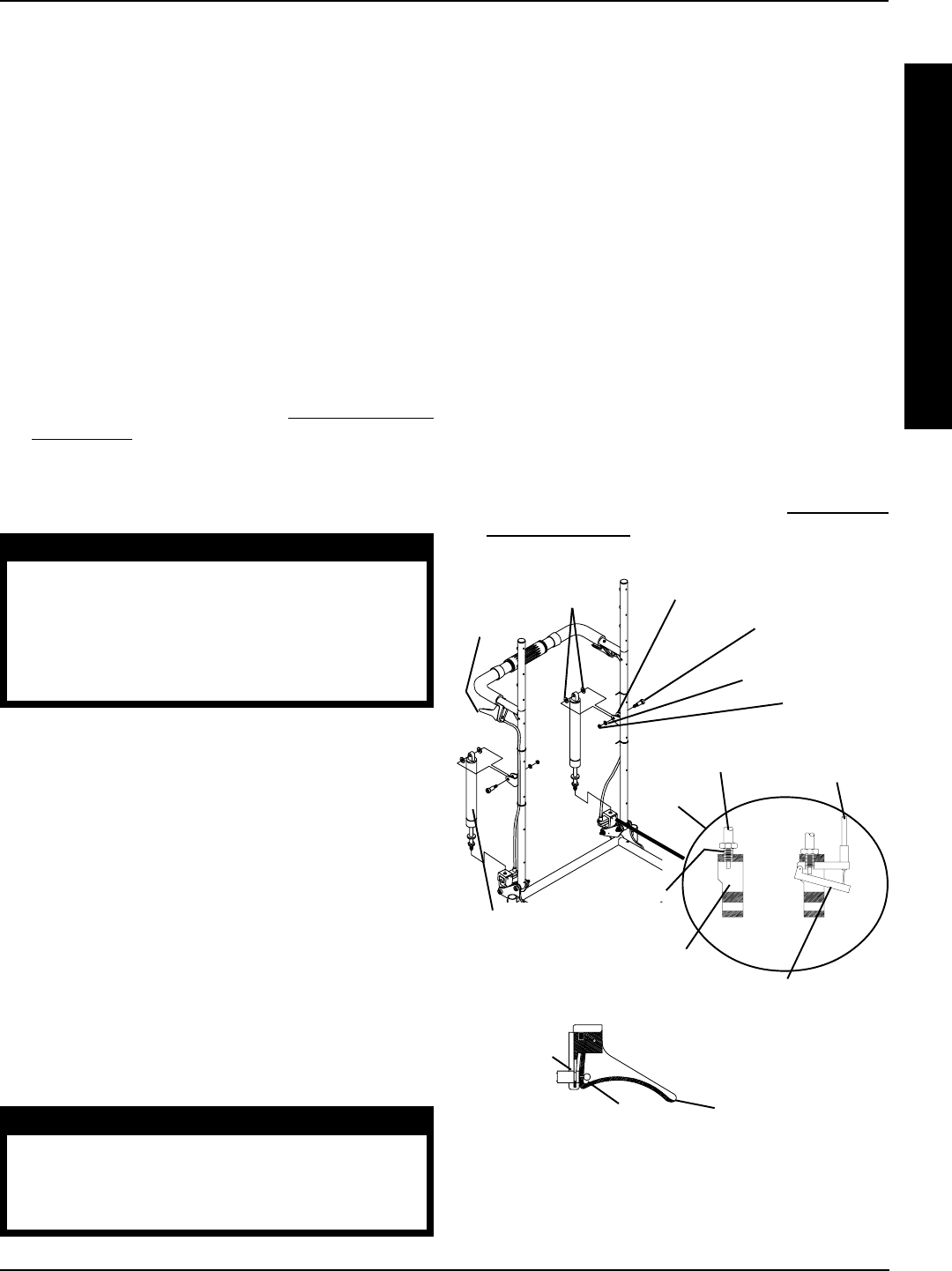
65
Gas Cylinder
Rod
Jam Nut
Gas
Cylinder
NO Movement in Operator
of the Recliner Cable
Assembly
Gas Cylinder
Rod Threads
Handle
No Slack
in Cable
FIGURE 4 - REPLACING/ADJUSTING GAS CYLINDERS
Handle
Cable Fitting
Seated Properly
Pivot Block
Cable
Snapped
into Slot
Nylon Washer
Locknut
Washer
Mounting
Screw
Mounting Bracket
If slack in the recliner cable or movement in the operator of
the cable assembly can not be eliminated, DO NOT use
the recliner cable assembly.
6. Screw the NEW gas cylinder into the operator of the
cable assembly until the jam nut sits on the pivot block,
there is no slack in recliner cable and there is no move-
ment in the operator of the recliner cable assembly.
7. Visually inspect the handle to make sure that the cable
is snapped completely into slot in handle and cable
fitting is seat properly in the handle.
8. Press the operator of the recliner cable assembly to
extend the NEW gas cylinder.
9. Line up the mounting holes of the NEW gas cylinder
and the bracket of the back cane.
10. Reinstall the mounting screw through the mounting
bracket of the back cane, nylon washer, NEW gas
cylinder, nylon washer, mounting bracket and washer
and securely tighten with the existing locknut. Torque
to 75-inch pounds.
11. Adjust the NEW gas cylinders. Refer to ADJUSTING
GAS CYLINDERS in this procedure of the manual.
R
E
C
L
I
N
E
R
10. Visually inspect the handle to make sure that the cable
is snapped completely into slot in handle and cable fit-
ting is seat properly in the handle.
11. Reinstall the mounting screw through the mounting
bracket of the back cane, nylon washer, gas cylinder,
nylon washer, mounting bracket and washer and se-
curely tighten with the existing locknut. Torque to 75-
inch pounds.
12. Line up the mounting hole in the handle of the recliner
cable assembly with the mounting hole in the back cane.
13. Insert the pan screw through the handle of the recliner
cable assembly and the back cane and torque to 9-inch
pounds.
14. Tie wrap the recliner cable assembly to the recliner back
cane.
15. Adjust the gas cylinder. Refer to ADJUSTING GAS
CYLINDERS in this procedure of the manual.
REPLACING/ADJUSTING GAS
CYLINDERS (FIGURE 4)
WARNING
Replace ONE (1) gas cylinder at a time to avoid
injury.
Both gas cylinders MUST be operational and ad-
justed properly BEFORE using the recliner. DO NOT
operate the recliner if only one (1) of the gas cylin-
ders is operational or adjusted properly.
Replacing Gas Cylinder
1. Remove the mounting screw, washer, nylon washers
and locknut that secure the TOP of the gas cylinder to
mounting bracket on back cane.
2. Loosen the jam nut on existing gas cylinder rod.
3. Unscrew the existing gas cylinder from the operator of
the recliner cable assembly and the pivot block and
remove the existing gas cylinder from the wheelchair.
4. Screw cylinder rod of the NEW gas cylinder into the
pivot block until the threads of the cylinder rod are flush
with inside of pivot block (FIGURE 4).
5. With the operator of the recliner cable assembly on
the inside of the recliner seat frame, line up the mount-
ing hole in the operator of the recliner cable assembly
with the new gas cylinder rod.
CAUTION
DO NOT force the gas cylinder rod into the opera-
tor of the recliner cable assembly.
DO NOT cross thread the operator of the recliner
cable assembly with the gas cylinder.
PROCEDURE 14RECLINER
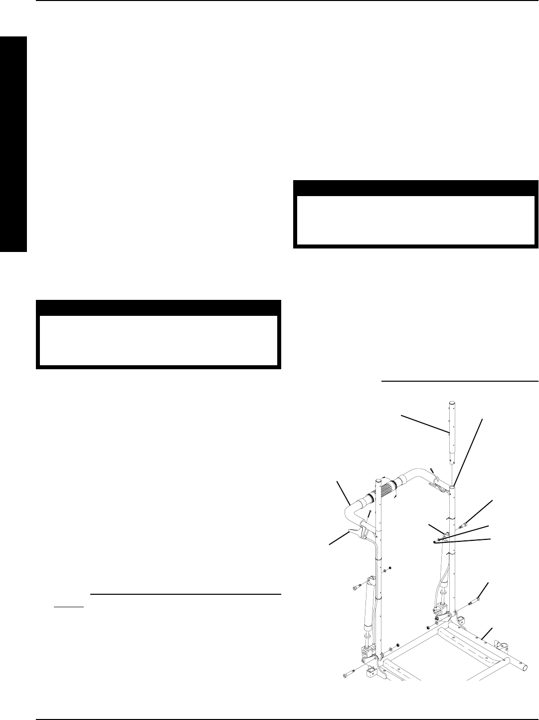
66
R
E
C
L
I
N
E
R
Adjusting Gas Cylinder
1. To adjust the LEFT gas cylinder: Squeeze the handle
of the RIGHT recliner cable assembly and try to re-
cline the back. The back should not recline.
2. If the LEFT side of the back releases without
squeezing the handle of the LEFT recliner cable
assembly, perform the following steps:
A. Finger tighten the jam nut on the rod of the gas
cylinder until it bottoms out on the rod of the
cylinder (FIGURE 4).
B. Turn the jam nut on the LEFT gas cylinder
COUNTERCLOCKWISE approximately one-
half (1/2) revolution.
NOTE: The gas cylinder rod will turn.
C. Repeat STEP 1.
D. Repeat STEP B until the LEFT side of the back
DOES NOT recline.
3. To adjust the RIGHT gas cylinder: Repeat STEPS
1 and 2 for the LEFT handle of the cable assembly.
CAUTION
Damage to the gas cylinder rod WILL oc-
cur if the following steps are NOT followed
when the jam nut is torqued against the
pivot block.
4. Using NO LARGER than 1/4-inch wide, fine toothed
pliers, wrap masking tape around the teeth of the
pliers two (2) or (3) revolutions.
5. Using NO excessive force, hold the gas cylinder
rod just above the jam nut.
6. While holding the gas cylinder rod and using a 17mm
wrench, turn the jam nut CLOCKWISE and torque
the RIGHT and LEFT jam nuts against the RIGHT
and LEFT pivot blocks to 156-inch pounds.
CHANGING BACK HEIGHT
(FIGURE 5)
1. Press the push pins on the headrest extension tubes
in and remove headrest extension from back canes.
2. Remove the recliner cables from the back canes.
Refer to REPLACING RECLINER CABLE ASSEM-
BLIES in this procedure of the manual.
3. Remove the mounting screws, washers and lock-
nuts that secure the TOP of the gas cylinders to the
mounting bracket on the back canes.
4. Remove the mounting screws, washers and lock-
nuts that secure the back canes to the seat frame.
5. Remove the existing recliner back assembly from
the wheelchair. FIGURE 5 - CHANGING BACK HEIGHT
Mounting
Screw
Washers
Locknut
Mounting
Screw
Back Cane
Spreader
Bar
NOTE: Upholstery not shown for clarity.
Headrest
Extension
Tube
Push
Pin
Seat Frame
Mounting
Bracket
PROCEDURE 14 RECLINER
6. Turn the spreader bar on the existing back canes
CLOCKWISE (toward back upholstery) and remove
the spreader bar from the existing back canes.
7. Loosely install the spreader bar onto the NEW back
cane handles by rotating the spreader bar COUN-
TERCLOCKWISE (away from the back canes).
NOTE: If the spreader bar does not thread onto the back
canes, do not force. Turn the spreader bar around and
repeat STEP 7.
8. Line up two (2) bottom mounting holes of back canes
with the two (2) mounting holes in the seat frame.
WARNING
The back canes MUST be fastened se-
curely to the seat frame BEFORE using the
wheelchair. Torque mounting screws to
156-inch pounds.
9. Reinstall the mounting screw, washer and locknut
through the back cane and seat frame mounting holes
and torque to 156-inch pounds.
10. Reinstall the mounting screw through the mounting
bracket of the back cane, nylon washer, mounting
hole in the TOP of the gas cylinder, nylon washer,
mounting bracket and washer and securely tighten
with the existing locknut. Torque to 75-inch pounds.
11. Reinstall the recliner cable assemblies onto the back
canes. Refer to REPLACING RECLINER CABLES
in this procedure of the manual.
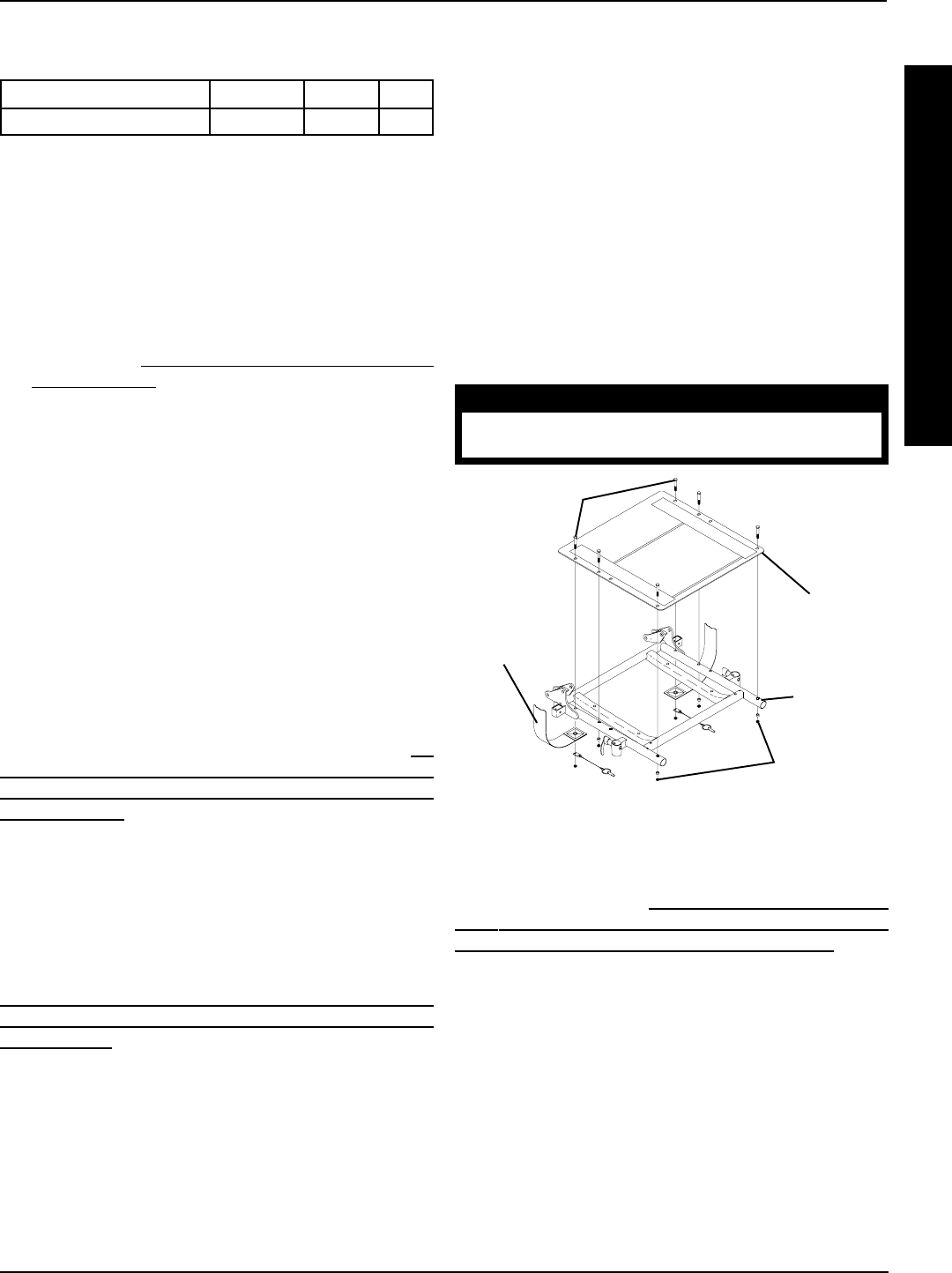
67
PROCEDURE 14RECLINER
Hex Screws
Seat Pan
Seat
Frame
FIGURE 6 - CHANGING SEAT DEPTH
Locknuts
Seat
Positioning
Strap
CHANGING SEAT WIDTH
To change seat width, the seat frame must be changed to
the desired width. Refer to INSTALLING/REPLACING AD-
JUSTABLE 16 TO 19-INCH DEEP RECLINER SEAT
FRAME ONTO ARROW OR X BASE FRAME in this
procedure of the manual.
NOTE: If changing the seat width of the wheelchair, the
back and headrest upholstery, seat pan and cushion also
need to be changed.
NOTE: If changing the seat width of the wheelchair, the back
canes, spreader bar and headrest pillow may also need to
be changed. Refer to the following charts:
BACK CANES AND SPREADER BAR SEAT WIDTH
RANGES
14-17-INCHES OR 18-24-INCHES
HEADREST PILLOWS SEAT WIDTH RANGES (IN
INCHES)
14-15, 16-18, 19-20 OR 21-24
R
E
C
L
I
N
E
R
NOTE: There are three (3) different cable lengths depending
on back height:
BACK HEIGHT (in inches) 18-1/2, 20 22, 24 26
CABLE LENGTH Short Medium Long
NOTE: New recliner cables will be needed if back height is
changed to a height not within the length of the original cable.
12. Install the NEW back upholstery onto the back canes.
13. Install the ten (10) or twelve (12) mounting screws
(depending on back height) that secure the back up-
holstery to the recliner back canes.
14. Reinstall headrest extension onto recliner back canes.
15. Adjust the tautness of the back and headrest uphol-
stery. Refer to ADJUSTING BACK OR HEADREST
UPHOLSTERY in this procedure of the manual.
CHANGING SEAT DEPTH (FIGURE 6)
NOTE: 16-inch, 17-inch, 18-inch or 19-inch seat depths CAN
NOT be increased to 20-inches or deeper. If needing to in-
crease to a seat depth of 20-inches or deeper, the base frame
MUST be converted from a STANDARD base frame to a
LONG base frame as well.
NOTE: 20-inch, 21-inch or 22-inch seat depths CAN NOT
be decreased to 19-inches or less. If needing to decrease to
a seat depth of 19-inches or less, the base frame MUST be
converted from a LONG base frame to a STANDARD base
frame.
To adjust seat depth of wheelchair, use following guidelines:
If the current seat depth is an ODD number, i.e., 17-inches,
19-inches or 21-inches, the seat depth CANNOT be IN-
CREASED without changing the seat frame. Refer to IN-
STALLING/REPLACING ADJUSTABLE 16 TO 19-INCH
DEEP RECLINER SEAT FRAME ONTO ARROW OR X
BASE FRAMES in this procedure of the manual.
If the current seat depth is an ODD number, i.e., 17-inches,
19-inches or 21-inches, the seat depth can be DECREASED
by 1-inch by installing a 1-inch shorter seat pan. Refer to the
following procedures:
If the current seat depth is an EVEN number, i.e., *16-inches,
18-inches, 20-inches or 22-inches, the seat depth CANNOT
be DECREASED without changing the seat frame. Refer to
INSTALLING/REPLACING ADJUSTABLE 16 TO 19-INCH
DEEP RECLINER SEAT FRAME ONTO ARROW OR X
BASE FRAME in this procedure of the manual.
*NOTE: 16-inch seat depth is the smallest seat depth avail-
able on recliner seat frames.
If the current seat depth is an EVEN number, i.e., 16-inches,
18-inches, 20-inches or *22-inches, the seat depth can be
INCREASED by 1-inch by installing a 1-inch deeper seat
pan. Refer to the following procedures:
*NOTE: 22-inch seat depth is the deepest seat depth avail-
able on recliner seat frames.
Seat Pan Removal/Replacement Procedures:
1. Remove the seat cushion from the wheelchair.
2. Remove the six (6) mounting screws and locknuts
that secure seat pan, seat positioning strap to the
seat frame.
3. Install new 1-inch deeper/shorter seat pan onto seat
frame.
4. Reinstall the mounting screws, spacers and lock-
nuts and torque to 75-inch pounds.
5. Remove the protective strips on the seat pan and
reinstall the seat cushion onto the seat pan.
NOTE: Clean upholstery with a warm damp cloth and mild
detergent to remove superficial soil.
WARNING
Laundering or moisture will reduce the flame
retardation of the upholstery.
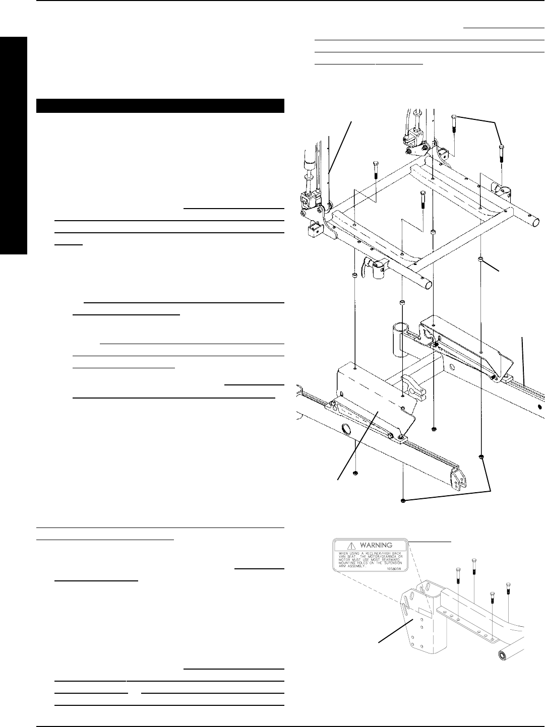
68
R
E
C
L
I
N
E
R
PROCEDURE 14 RECLINER
FIGURE 7 - INSTALLING/REPLACING ADJUSTABLE 16
TO 19-INCH DEEP RECLINER SEAT FRAME ONTO
ARROW OR X BASE
Mounting
Screws
Base
Frame
Spacer
Recliner
Seat Assembly
Seat Mount
Plate
Locknuts
If the seat width required is within the range of the original
back canes, spreader bar and headrest pillow, the original
components can still be used.
If the seat width required is NOT within the range of the origi-
nal back canes, spreader bar and headrest pillow, the origi-
nal components can not be used.
EQUIPMENT OPTION
INSTALLING/REPLACING
ADJUSTABLE 16 TO 19-INCH DEEP
RECLINER SEAT FRAME ONTO
ARROW OR X BASE FRAME
(FIGURE 7)
1. Perform instructions outlined in PREPARATIONS FOR
REMOVING/INSTALLING SEAT FRAME (STANDARD
FRAME, ADJUSTABLE FRAME, AND CAPTAINS VAN
SEAT) in PROCEDURE 6 of this manual:
2. Perform one (1) of the following in PROCEDURE 7 of
this manual:
A. Remove standard seat frame subassembly. Refer
to REMOVING/INSTALLING STANDARD SEAT
FRAME SUBASSEMBLY.
B. Remove adjustable seat frame subassembly. Re-
fer to INSTALLING/REMOVING ADJUSTABLE
SEAT FRAME ASSEMBLY AND OR COMPO-
NENT REPLACEMENT.
C. Remove captains van seat. Refer to INSTALLING/
REMOVING CAPTAINS VAN SEAT ASSEMBLY.
3. Remove seat pan on recliner.
4. Install new recliner seat assembly onto seat mount plates.
5. Secure recliner seat assembly to seat mount plates with
the mounting screws, spacers and locknuts. Torque the
mounting screws to 156-inch pounds.
NOTE: There are three (3) types of seat mount plates; low,
medium, and high heights. The seat mount plate shown in
this illustration represents the medium height. Refer to
MOUNTING PLATE - SEAT ANGLE ADJUSTMENT AND
INSTALLATION ORIENTATION in PROCEDURE 6 of this
manual for illustrations of the low and high heights.
6. Position limit switch onto wheelchair. Refer to POSITION-
ING LIMIT SWITCH in this procedure of the manual.
7. Reinstall recliner seat pan with existing six (6) mount-
ing screws.
8. Install the two (2) warnings labels onto the two (2)
suspension arm assemblies. Refer to FIGURE 7 for
correct label placement.
9. Install battery box(es). Refer to INSTALLING/REMOV-
ING BATTERY BOXES- GROUP 24 BATTERY
BASE FRAMES or INSTALLING/REMOVING BAT-
TERY BOX - GROUP 22 BATTERY BASE FRAMES
in PROCEDURE 9 of this manual.
10. Perform instructions outlined in PREPARATIONS
FOR REMOVING/INSTALLING SEAT FRAME
(STANDARD FRAME, ADJUSTABLE FRAME, AND
CAPTAINS VAN SEAT) in PROCEDURE 6 of this
manual:
Warning Label
Inside of
Suspension Arm
Assembly

69
PROCEDURE 15MWD WHEELCHAIRS
M
W
D
W
H
E
E
L
C
H
A
I
R
S
This Procedure includes the following:
Removing/Installing Group 24 Battery Box Sub-Frame
Removing/Installing Group 22 Battery Box Tray
Converting Group 22 Batteries To Group 24 Batteries
Shock Replacement
Shock Spring Replacement
Replacing Stabilizer Fork Assembly
Replacing Stabilizer Wheels
Replacing Stabilizer Cylinder Springs
Adjusting Weight Distribution
Adjusting Stabilizers
Installing/Removing Gearbox
Replacing Suspension Arm
Spacer
Battery Box
Retainer
Bar
Retainer Clip
FIGURE 1 - REMOVING/INSTALLING GROUP 24 BATTERY
BOX SUB-FRAME
Battery Box Sub-frame
REMOVING/INSTALLING GROUP 24
BATTERY BOX SUB-FRAME (FIGURE 1)
Removing
1. Remove the battery boxes. Refer to INSTALLING/RE-
MOVING GROUP 24 BATTERY BOXES in PROCE-
DURE 9 of this manual.
2. Remove the two (2) mounting screws and locknuts
that secure the wiring harness w/bracket and the rear
of the existing sub-frame to the base frame. Refer to
REMOVING/INSTALLING WIRING HARNESS in
PROCEDURE 10 of this manual.
3. Remove the four (4) mounting screws that secure the
shocks, retainer bar, spacers and retainer clips to the
base frame. Refer to REPLACING BATTERY BOX
RETAINER/RETAINER CLIP - GROUP 24 BATTERY
BASE FRAMES in PROCEDURE 11 of this manual.
4. Remove the existing sub-frame assembly.
Installing
1. Install the two (2) mounting screws and locknuts that
secure the wiring harness w/bracket and the back of
the NEW sub-frame to the base frame. Refer to RE-
MOVING/INSTALLING THE WIRING HARNESS in
PROCEDURE 10 of this manual. Use Loctite 242 and
torque mounting screws to 160-inch pounds.
Mounting
Screws
Wiring Harness
w/Bracket
Sub-Frame
Locknuts
REAR OF CHAIR
REAR OF
CHAIR
FRONT OF CHAIR
Mounting
Screws
FRONT OF
CHAIR
2. Reinstall the four (4) mounting screws that secure the
shocks, retainer bar, spacers and retainer clips to the
base frame. Refer to REPLACING BATTERY BOX
RETAINER/RETAINER CLIP - GROUP 24 BATTERY
BASE FRAMES in PROCEDURE 11 of this manual.
Use Loctite 242 and torque mounting screws to 160-
inch pounds.
3. Reinstall the battery boxes. Refer to INSTALLING/RE-
MOVING GROUP 24 BATTERY BOXES in PRO-
CEDURE 9 of this manual. Use Loctite 242 and torque
mounting screws to 160-inch pounds.
WARNING
After ANY adjustments, repair or service and BE-
FORE use, make sure that all attaching hardware
is tightened securely - otherwise injury or dam-
age may result.
REMOVING/INSTALLING GROUP
22 BATTERY BOX TRAY (FIGURE 2)
Removing
1. Remove battery box. Refer to INSTALLING/REMOV-
ING GROUP 22 BATTERY BOX in PROCEDURE 9
of this manual.
2. Remove the two (2) mounting screws and locknuts
that secure rear of battery box tray to the base frame.
3. Remove the two (2) front locknuts that secure the bat-
tery box tray to battery mount brackets.
4. Remove the battery box tray.
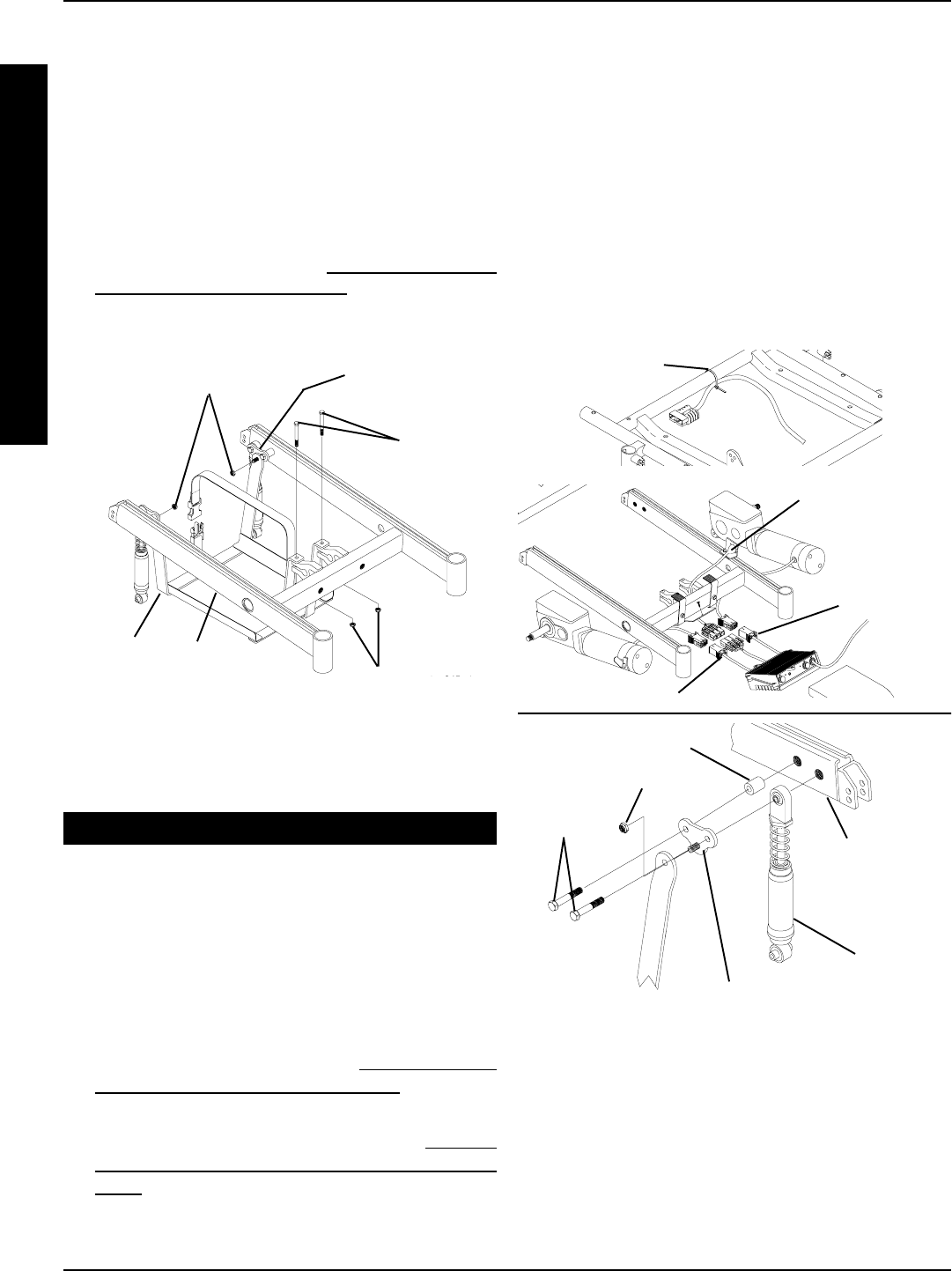
70
PROCEDURE 15 MWD WHEELCHAIRS
Battery
Box Tray
Base
Frame
Front Locknuts
Mounting
Screws
FIGURE 2 - REMOVING/INSTALLING GROUP 22
BATTERY BOX TRAY
REAR OF
CHAIR
FRONT OF
CHAIR
Rear Locknuts
Battery Mount
Bracket
EQUIPMENT OPTION
CONVERTING GROUP 22 BATTERY
BOX TRAY TO GROUP 24 BATTERY
BOX SUB FRAME
NOTE: The battery box tray and battery mount brackets will
not be used with this option. Keep for future use.
Removing Group 22 Components (FIGURE 3)
1. Remove the battery box. Refer to INSTALLING/RE-
MOVING GROUP 22 BATTERY BOX in PROCE-
DURE 9 of this manual.
2. Remove the existing battery box tray. Refer to REMOV-
ING/INSTALLING THE GROUP 22 BATTERY BOX
TRAY in this procedure of the manual.
FIGURE 3 - REMOVING GROUP 22 COMPONENTS
Battery Mount Bracket
Mounting
Screws
Spacer
Base Frame
Locknut
Shock
Tie Wrap
Motor Connector
Charger Cable/
Bracket
Motor
Connector
3. Disconnect the right and left motor connectors from
the controller connectors.
4. Remove the two (2) mounting screws that secure
the charger cable to the mount bracket.
5. Remove the charger cable from the mount bracket.
5. Cut the tie-wrap that secures the wiring harness to
the seat frame.
6. Remove the wiring harness.
7. Remove the four (4) mounting screws that secure
the battery mount brackets to the base frame and
remove the battery mount brackets.
Installing Group 24 Components (FIGURE 4)
1. Align the mounting holes of the NEW wiring harness
w/bracket, the NEW battery box sub-frame and the
mounting holes in the base frame.
2. Install the two (2) mounting screws through all three (3)
parts and secure with locknuts. Torque to 160-inch
pounds.
M
W
D
W
H
E
E
L
C
H
A
I
R
S
Installing
1. Install battery box tray onto base frame.
2. Secure the front of the battery box tray to battery
mount brackets with existing locknuts. Torque to
160-inch pounds.
3. Secure the rear of the battery box tray to the base
frame with existing mounting screws and locknuts.
Torque to 160-inch pounds.
4. Reinstall the battery box. Refer to INSTALLING/REMOV-
ING GROUP 22 BATTERY BOX in PROCEDURE 9
of this manual.
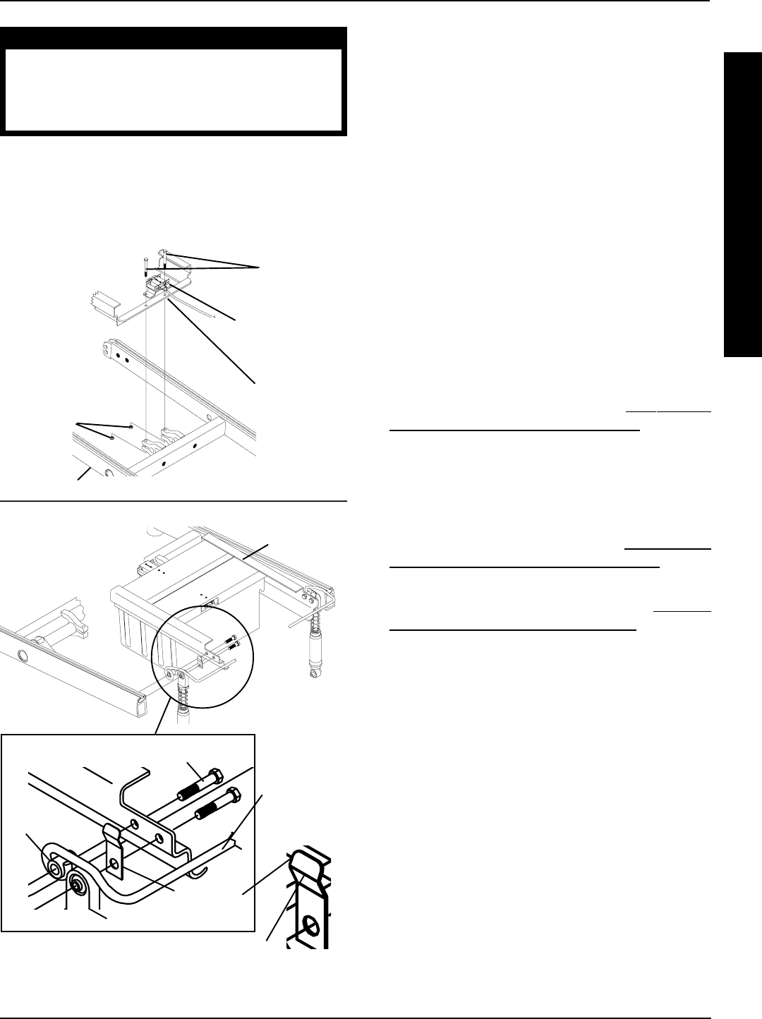
71
FIGURE 4 - INSTALLING GROUP 24 COMPONENTS
Mounting
Screws
Wiring Harness
w/Bracket
Battery Box
Sub-Frame
Locknuts
REAR OF CHAIR
FRONT OF
CHAIR
Spacer
Battery Box
Retainer
Bar
Battery Box
Sub-frame
REAR OF
CHAIR
Mounting Screws
Base Frame
Shock
Closed End
Retainer
Clip
STEPS 1-2
STEPS 3-6
FRONT OF
CHAIR
WARNING
The Battery Box Retainer/Retainer Clip
MUST be fastened securely in place be-
fore using the wheelchair. Use Loctite 242
and torque to 160-inch pounds.
3. Position the NEW retainer clip between the NEW bat-
tery box sub-frame and shock making sure the retainer
clip mounting hole is towards the bottom and the closed
end of the clip is against the battery box retainer bar.
4. Install the mounting screw that secures the retainer
clip to the battery box sub-frame. Use Loctite 242 and
torque to 160-inch pounds.
5. Align the NEW battery box retainer and spacers with
the mounting holes in the base frame making sure the
closed end of the battery box retainer is pointing up.
6. Reinstall the mounting screws that secure the battery
box retainer to the base frame. Use Loctite 242 and
torque to 160-inch pounds.
7. Install charger cable to existing mounting bracket se-
cure with existing two (2) mounting screws.
8. Tie-wrap NEW wiring harness to the seat frame.
9. Connect the following cables:
a. The right and left motor connectors to the control-
ler connectors.
b. The battery harness/charger cable (BLUE) to the
controller connector (BLUE).
10. Install the NEW battery boxes. Refer to INSTALLING/
REMOVING GROUP 22 BATTERY BOX in PROCE-
DURE 9 of this manual.
SHOCK REPLACEMENT
Group 24 Battery Base Frames (FIGURE 5)
1. Remove the front battery box. Refer to INSTALLING/
REMOVING GROUP 24 BATTERY BOXES in PRO-
CEDURE 9 of this manual.
2. Remove the drive wheel assembly. Refer to REMOV-
ING/INSTALLING THE DRIVE WHEEL in PROCE-
DURE 12 of this manual.
3. Loosen the mounting screw that secures the battery
box retainer between the battery box sub frame as-
sembly and the base frame.
4. Remove the mounting screw that secures the top of
the shock and retainer clip between the battery box
sub frame assembly and the base frame.
NOTE: Remove and hold onto the retainer clip for instal-
lation of the NEW shock.
5. Remove the mounting screw, two (2) flat washers,
two (2) spring washers, two (2) inner link spacers,
and locknut that secures the bottom of the shock,
suspension arm, and stabilizer bracket together.
6. Remove the existing shock.
7. Install the NEW shock.
M
W
D
W
H
E
E
L
C
H
A
I
R
S
MWD WHEELCHAIRS PROCEDURE 15
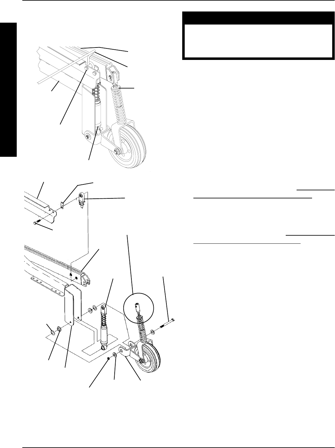
72
PROCEDURE 15 MWD WHEELCHAIRS
8. Secure the bottom of the NEW shock, suspension arm,
and stabilizer bracket together with the mounting screw,
two (2) flat washers, two (2) spring washers, two (2) inner
link spacers, and locknut. Torque to 160-inch pounds.
WARNING
The Battery Box Retainer/Retainer Clip
MUST be fastened securely in place be-
fore using the wheelchair. Use Loctite 242
and torque to 160-inch pounds.
9. Position retainer clip between shock and battery box
sub-frame making sure the retainer clip mounting hole
is towards the bottom and the closed end of clip is
against battery box retainer.
10. Secure top of shock and retainer clip between battery
box sub frame and base frame. Apply Loctite 242 and
torque to 160-inch pounds.
11. Apply Loctite 242 and torque the mounting screw that
secures the battery box retainer between the battery box
sub frame and base frame. Torque to 160-inch pounds.
12. Reassemble large wheel to hub assembly and Torque
to 160-inch pounds.
13. Repeat this procedure for the opposite shock.
14. Reinstall the front battery box. Refer to INSTALLING/
REMOVING GROUP 24 BATTERY BOXES in PRO-
CEDURE 9 of this manual.
Group 22 Battery Base Frames (FIGURE 6)
1. Remove the battery box. Refer to INSTALLING/RE-
MOVING GROUP 22 BATTERY BOX in PROCE-
DURE 9 of this manual.
2. Remove the four (4) nuts that secure the large wheel
assembly to the to the hub assembly and remove the
large wheel assembly.
3. Loosen the mounting screw that secures the spacer
between battery mount bracket and the base frame.
4. Remove mounting screw that secures top of the shock
between battery mount bracket and base frame.
5. Remove the mounting screw, two (2) flat washers,
two (2) spring washers, two (2) inner link spacers,
and locknut that secures the bottom of the shock,
suspension arm, and stabilizer bracket together.
6. Remove the existing shock.
7. Install the NEW shock.
8. Secure the bottom of the NEW shock, suspension arm,
and stabilizer bracket together with the mounting screw,
two (2) flat washers, two (2) spring washers, two (2) inner
link spacers, and locknut. Torque to 160-inch pounds.
9. Secure the top of shock between battery mount
bracket and base frame. Apply Loctite 242 and torque
to 160-inch pounds.
Mounting Screw
Loosen, DO NOT
REMOVE (STEPS
3,11)
Battery Box
Retainer Bar
Battery Box
Sub- Frame
Base Frame
FIGURE 5 - SHOCK REPLACEMENT - GROUP 24
BATTERY BASE FRAMES
Stabilizer
Assembly*
Shock
Battery Box Sub-Frame
Inner Link
Spacer
Spring
Washer
Mounting
Screw
Retainer Clip
Top of Shock
Mounting
Screw
Base
Frame
Flat Washer
Locknut
NOTE: Top of stabilizer*
exploded away for clarity only.
Suspension
Arm Stabilizer
Bracket
Shock
M
W
D
W
H
E
E
L
C
H
A
I
R
S
NOTE: The spacer and retainer are not shown for clarity.
*NOTE: The spring shown on the stabilizer is for wheel-
chair models built before 7/1/1999
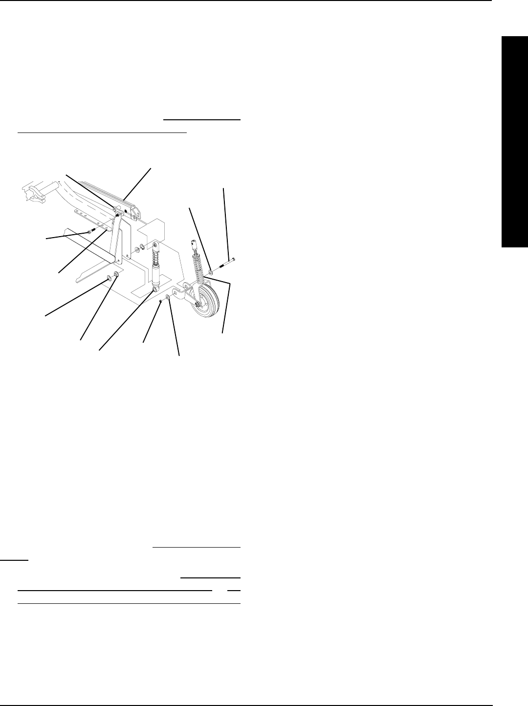
73
10. Apply Loctite 242 and torque the mounting screw that
secures the spacer between the battery mount bracket
and base frame. Torque to 160-inch pounds.
11. Reassemble large wheel to hub assembly and Torque
to 160-inch pounds.
12. Repeat this procedure for the opposite shock.
13. Reinstall the battery box. Refer to INSTALLING/RE-
MOVING GROUP 22 BATTERY BOX in PROCE-
DURE 9 of this manual.
FIGURE 6 - SHOCK REPLACEMENT - GROUP 22
BATTERY BASE FRAMES
Shock
Base Frame
Flat Washer
Locknut
Spring
Washer
NOTE: Top of stabilizer exploded away for clarity only.
*NOTE: The spring shown on the stabilizer is for wheel-
chair models built before 7/1/1999
Inner Link Spacer
Mounting
Screw
Stabilizer*
Mounting
Screw
Stabilizer Bracket
Suspension
Arm
Battery Mount Bracket
B. (Group 22 Battery Base Frames) Loosen the
mounting screw that secures the battery box
spacer between the battery box tray mount bracket
and the base frame.
3. Remove the mounting screw that secures the top of
the stabilizer cylinder to the base frame.
4. Perform one (1) of the following:
A. (Group 24 Battery Base Frames) Remove the
mounting screw that secures the top of the shock
between the battery box sub-frame and the base
frame.
B. (Group 22 Battery Base Frames) Remove the
mounting screw that secures the top of the shock
between retainer clip and the battery box tray
mount bracket and the base frame.
NOTE: (Group 24 Battery Base Frames Only) Remove
and hold onto the retainer clip for reinstallation of shock.
5. Swing the top of both the stabilizer cylinder and the
shock forward.
6. Hold the spring retainer and turn the shock eyelet as-
sembly COUNTERCLOCKWISE to unthread it from
the shock.
7. Remove the spring retainer and spring.
8. Place the NEW spring onto the shock.
9. Reinstall the shock eyelet assembly and the spring
retainer onto the NEW spring.
10. While holding the spring retainer, torque the shock
eyelet assembly to 245-inch pounds.
11. (Group 24 Battery Base Frames) Position the re-
tainer clip between the shock and the battery box sub-
frame making sure the retainer clip mounting hole is
towards the bottom and the closed end of the clip is
against the battery box retainer.
12. Perform one (1) of the following:
A. (Group 24 Battery Base Frames) Apply Loctite
242 and torque the mounting screw that secures
the battery box retainer to the base frame to 160-
inch pounds.
B. (Group 22 Battery Base Frames) Apply Loctite
242 and torque the mounting screw that secures
the battery mount bracket to the base frame to
160-inch pounds.
13. Secure the top of the shock and retainer clip (Group
24) to base frame. Apply Loctite 242 and torque to
160-inch pounds.
SHOCK SPRING REPLACEMENT
(FIGURE 7)
NOTE: Heavy Duty Models Only. Shock springs on stan-
dard models cannot be individually replaced. A new shock
assembly must be installed. Refer to SHOCK REPLACE-
MENT in this procedure of the manual.
1. Remove the front battery box. Refer to INSTALLING/
REMOVING GROUP 24 BATTERY BOXES or IN-
STALLING/REMOVING GROUP 22 BATTERY BOX
in PROCEDURE 9 of this manual.
2. Perform one (1) of the following:
A. (Group 24 Battery Base Frames) Loosen the
mounting screw that secures the battery box re-
tainer between the battery box sub frame assem-
bly and the base frame.
M
W
D
W
H
E
E
L
C
H
A
I
R
S
MWD WHEELCHAIRS PROCEDURE 15
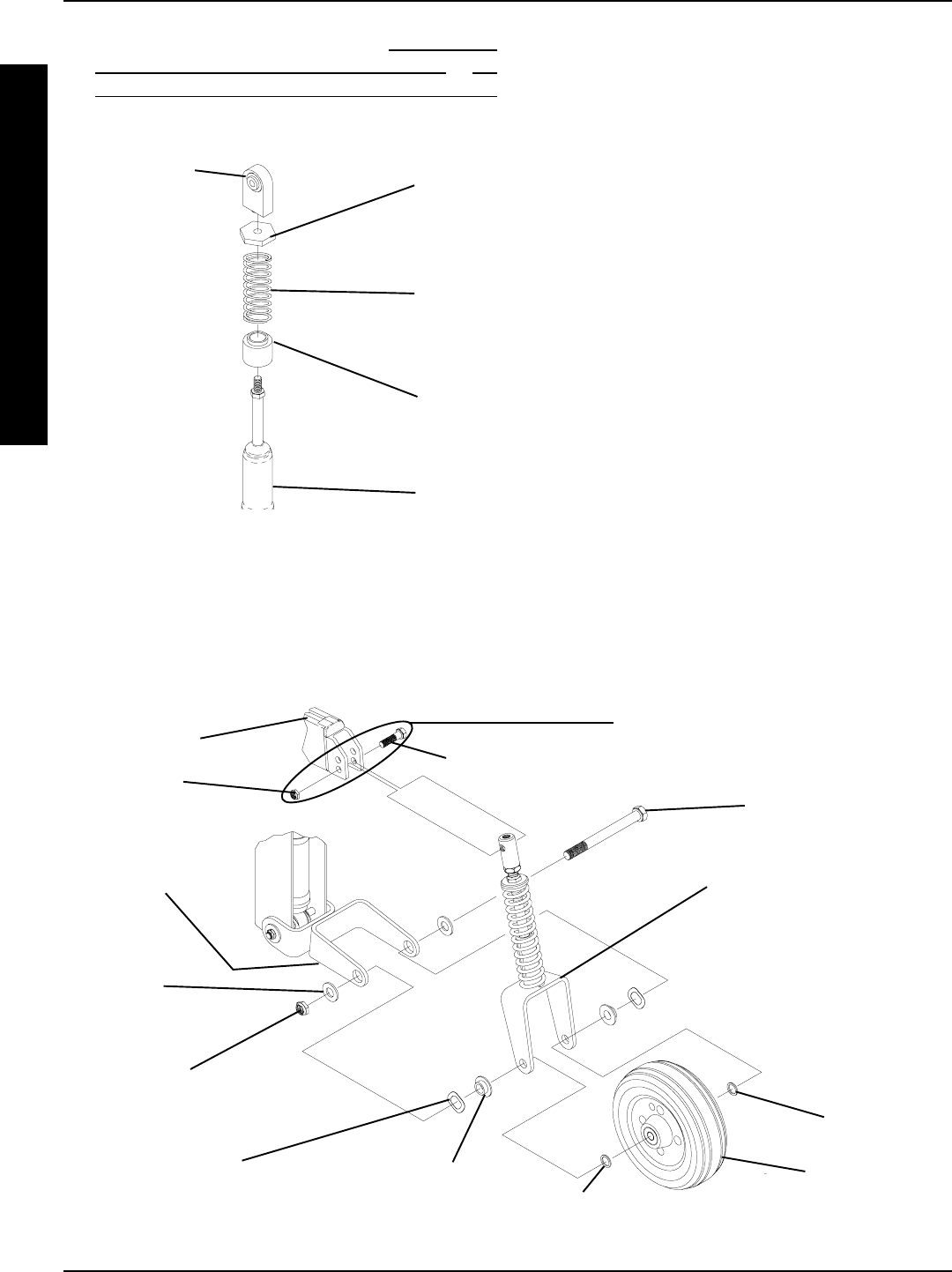
74
PROCEDURE 15 MWD WHEELCHAIRS
FIGURE 8 - REPLACING STABILIZER FORK ASSEMBLY/REPLACING STABILIZER WHEELS
Base Frame
Stabilizer
Fork
Assembly*
Mounting Screw
Flat
Washer
Washer
Spring Washer Outer Link Spacers
Locknut
NOTE: Remove this mounting screw and
locknut only when replacing the stabilizer
fork assembly.
Stabilizer
Bracket
Locknut Mounting Screw
Stabilizer Wheel
Washer
FIGURE 7 - SHOCK SPRING REPLACEMENT
Shock Eyelet
Assembly Spring
Retainer
Shock
Spring
Spring
Base
Shock
14. Reinstall the front battery box. Refer to INSTALLING/
REMOVING GROUP 24 BATTERY BOXES or IN-
STALLING/REMOVING GROUP 22 BATTERY BOX
in PROCEDURE 9 of this manual.
2. Remove the mounting screw, two (2) washers, two
(2) spring washers, two (2) outer link spacers, two
(2) flat washers, and locknut that secure the stabi-
lizer fork assembly, stabilizer bracket, and stabi-
lizer wheel together.
3. Secure NEW stabilizer fork assembly to stabilizer
bracket and stabilizer wheel with existing mount-
ing screw, two (2) washers, two (2) spring wash-
ers, two (2) outer link spacers, two (2) flat wash-
ers, and locknut. Securely tighten.
4. Secure top of stabilizer fork assembly to base frame
with existing mounting screw and locknut. Torque to
40 in/lbs.
REPLACING STABILIZER WHEELS
(FIGURE 8)
1. Remove the mounting screw, two (2) washers, two
(2) spring washers, two (2) outer link spacers, two
(2) flat washers, and locknut that secure the stabi-
lizer wheel, stabilizer bracket, and stabilizer fork
assembly together.
2. Secure NEW stabilizer wheel to stabilizer bracket
and stabilizer fork assembly with existing mount-
ing screw, two (2) washers, two (2) spring wash-
ers, two (2) outer link spacers, two (2) flat wash-
ers, and locknut. Securely tighten.
REPLACING STABILIZER FORK
ASSEMBLY (FIGURE 8)
1. Remove the mounting screw and locknut that secures
the top of the stabilizer fork assembly to the base frame.
M
W
D
W
H
E
E
L
C
H
A
I
R
S
*NOTE: The spring shown on the stabilizer fork assembly is for wheelchair models built before 7/1/1999
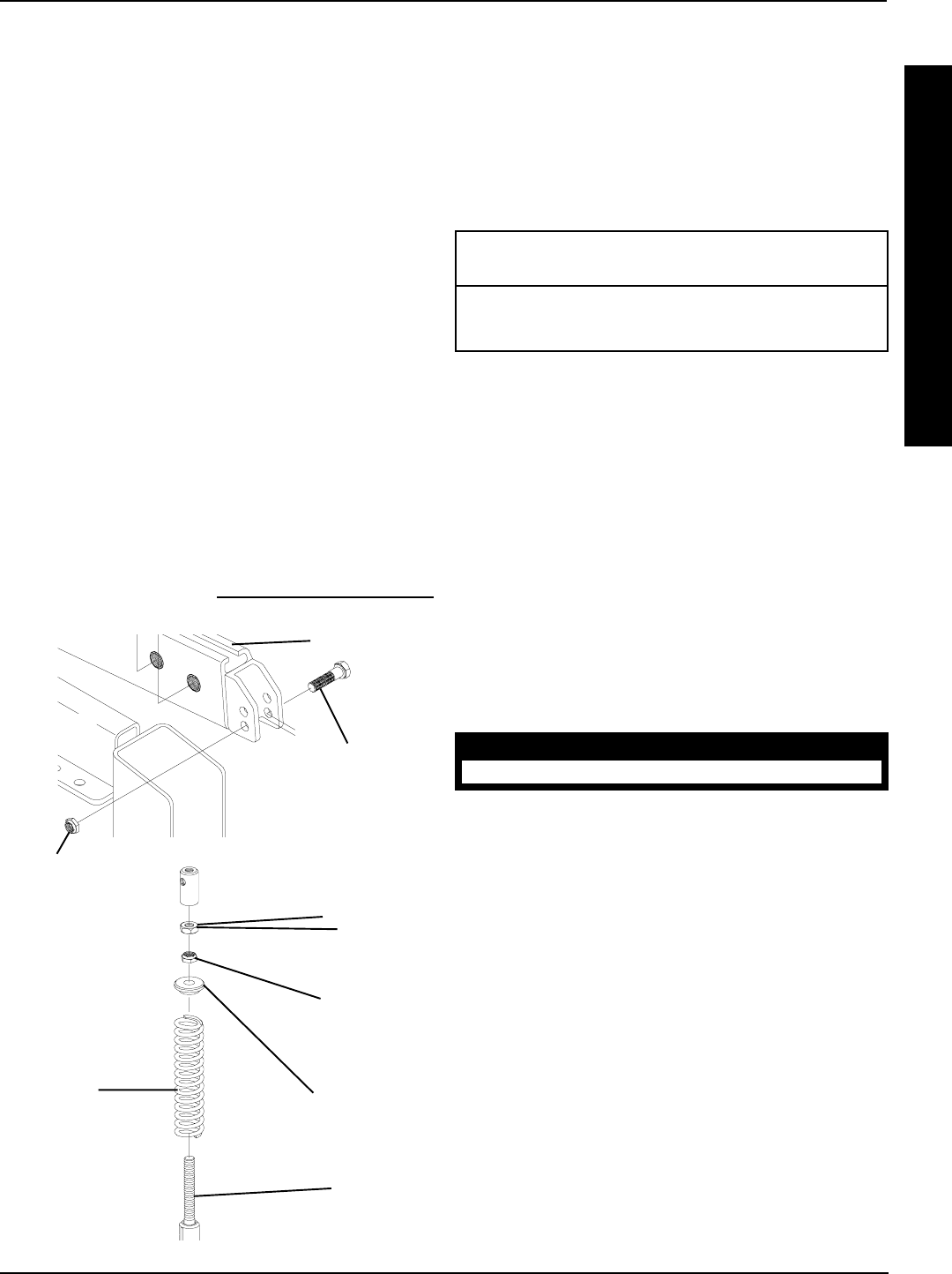
75
FIGURE 9 - REPLACING STABILIZER CYLINDER SPRING
Base Frame
Adjustment
Barrel
Stabilizer
Rod
Jam Nut
Adjustment
Nut
Spring
Retainer
Stabilizer
Spring
REPLACING STABILIZER
CYLINDER SPRING (FIGURE 9)
NOTE: Stabilizer springs are only on wheelchair mod-
els built before 7/1/1999.
1. Remove mounting screw and locknut that secures
top of the stabilizer fork assembly to the base frame.
2. Unthread adjustment barrel and remove from stabi-
lizer rod.
3. Unthread jam nut and remove from stabilizer rod.
4. Unthread adjustment nut and remove from stabilizer
rod.
5. Remove spring retainer from stabilizer rod.
6. Remove existing stabilizer spring.
7. Install NEW stabilizer spring.
8. Reinstall spring retainer.
9. Reinstall adjustment nut.
10. Reinstall jam nut.
11. Reinstall adjustment barrel.
12. Adjust stabilizer. Refer to ADJUSTING STABILIZERS
in this procedure of the manual.
Locknut
Mounting
Screw
ADJUSTING WEIGHT DISTRIBUTION
(FIGURE 10)
NOTE: The seat mount plates and seat support brackets
allow seat frame to be repositioned along the base frame.
NOTE: The position of the seat support brackets is factory
set at 5-1/2-inches from the front end of the base frame.
Use the following chart as a starting point.
Weight of Distance of Seat
User Support Bracket*
under 200-lbs 5-7-inches
over 200-lbs 6-8-inches
* Distance measured from the front of the base frame to
the front of the seat support bracket.
NOTE: Following the above chart will put 85-90% of the
total weight of the chair and user over the large wheels.
However, these settings may not be the most desirable in
terms of maneuverability and comfort for the user.
Adjustment for Optimum Performance
1. Loosen the four (4) mounting screws that secure the
seat support brackets to the base frame.
2. Adjust seat back until one (1) of the following occurs:
A. The clearance of the front riggings and the stabi-
lizers is at a minimum or
B. The rear stop is contacted.
WARNING
DO NOT adjust seat beyond limit stops.
3. Retighten mounting screws securing the seat support
brackets to the base frame.
4. Test wheelchair for handling.
5. If handling of the power wheelchair is drifting, repeat
this procedure moving seat up in small increments until
the chair handles properly.
6. Once the seat is adjusted to the point of proper han-
dling, comfort adjustments can be made
7. Check distance the stabilizer wheels are off the floor.
A. If distance is between 3/8 and 1/2-inches off of the
floor the user will experience a normal amount of
rocking when stopping or negotiating steeper in-
clines, depending on the amount of braking.
B. If distance is greater than 1/2-inches off of floor
the amount of rocking the user experiences when
stopping or negotiating steeper inclines will in-
crease.
M
W
D
W
H
E
E
L
C
H
A
I
R
S
MWD WHEELCHAIRS PROCEDURE 15
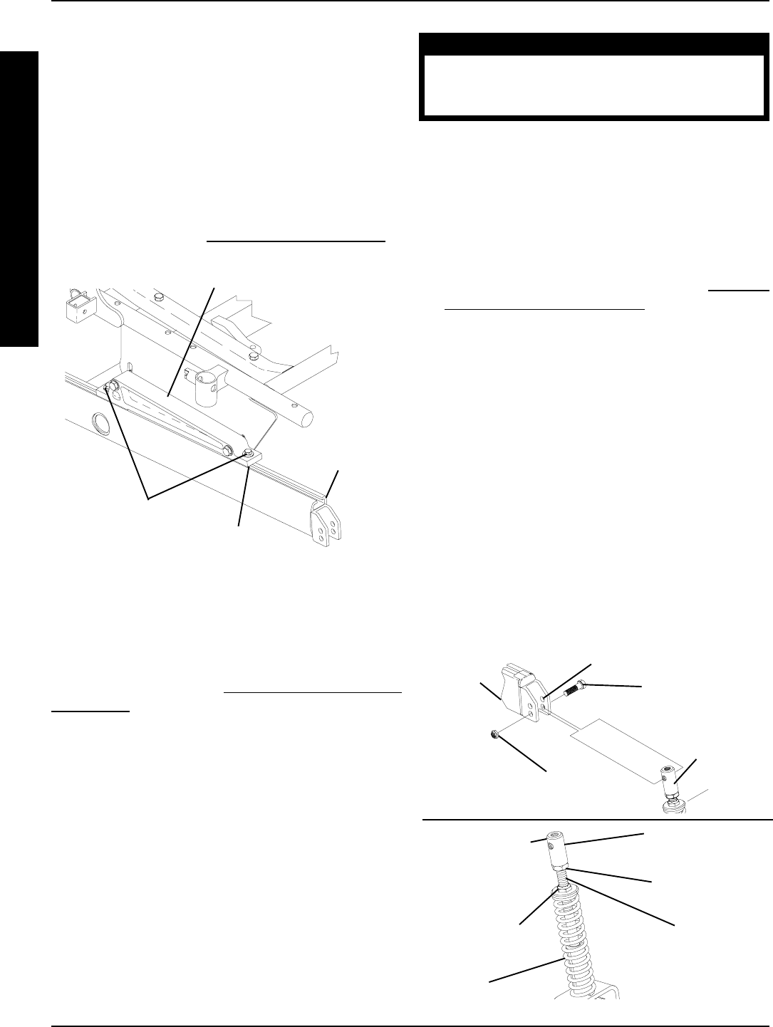
76
WARNING
The threaded rod must be engaged in the
adjustment barrel at least eight (8) full threads.
Otherwise, injury or damage may occur.
5. Realign the top of stabilizer fork assembly with the
mounting hole in the base frame noted earlier.
NOTE: Further height adjustment can be accomplished
by using the alternate mounting hole in the base frame.
See DETAIL A.
6. Secure stabilizer to base frame with existing mount-
ing screw and locknut.
7. To increase spring compression, refer to ADJUST-
ING SPRING COMPRESSION in this procedure of
the manual.
NOTE: Adjust both stabilizers equally to maintain proper
handling.
8. Repeat for opposite stabilizer.
9. Test wheelchair for handling/maneuverability.
10. Repeat STEPS 1-7 until desired comfort and ma-
neuverability is achieved
Adjusting Spring Compression
1. Perform one (1) of the following
A. To increase spring compression, turn adjustment
nut CLOCKWISE two (2) to four (4) revolutions.
B. To decrease spring compression, turn adjustment
nut COUNTERCLOCKWISE two (2) to four (4)
revolutions.
FIGURE 11 - ADJUSTING STABILIZERS
Adjustment
Barrel
Spring
Mounting Screw
Top of
Stabilizer Fork
Assembly
Base
Frame
Locknut
Jam Nut
Alternate Mounting Hole
DETAIL A
Adjustment Nut Threaded
Rod
Top of Stabilizer
Fork Assembly
NOTE: This setting would allow the wheelchair to
roll better on thicker carpeting and minimize scuff-
ing.
C. If distance is between 0 and 3/8-inch, along with
an increase in spring compression, the amount
of rocking the user experiences will decrease. Al-
though, this setting would minimize rocking, ob-
stacles protruding from the ground as well as ne-
gotiating steeper inclines will be more difficult.
8. Adjust the stabilizers to the desired setting determined
in STEP 7. Refer to ADJUSTING STABILIZERS in
this procedure of the manual.
Mounting Screws
(Two (2) on each
bracket)
Seat Support Bracket
Front of
Base Frame
Front of Seat
Support Bracket
FIGURE 10 -ADJUSTING WEIGHT DISTRIBUTION
ADJUSTING STABILIZERS
(FIGURE 11)
NOTE: Adjust the stabilizers to the desired handling/ma-
neuverability determined in ADJUSTING WEIGHT DIS-
TRIBUTION in this procedure of the manual.
NOTE: Note the mounting position of the stabilizer to the
base frame for proper reinstallation.
Height Adjustment
1. Remove the mounting screw and locknut that secures
the top of the stabilizer fork assembly to the base
frame.
2. Swing top end of stabilizer fork assembly forward.
3. Loosen jam nut, located below adjustment barrel.
4. Perform one (1) of the following:
Turn the adjustment barrel CLOCKWISE to raise the
stabilizer wheel.
Turn the adjustment barrel COUNTERCLOCKWISE
to lower the stabilizer wheel.
M
W
D
W
H
E
E
L
C
H
A
I
R
S
MWD WHEELCHAIRSPROCEDURE 15
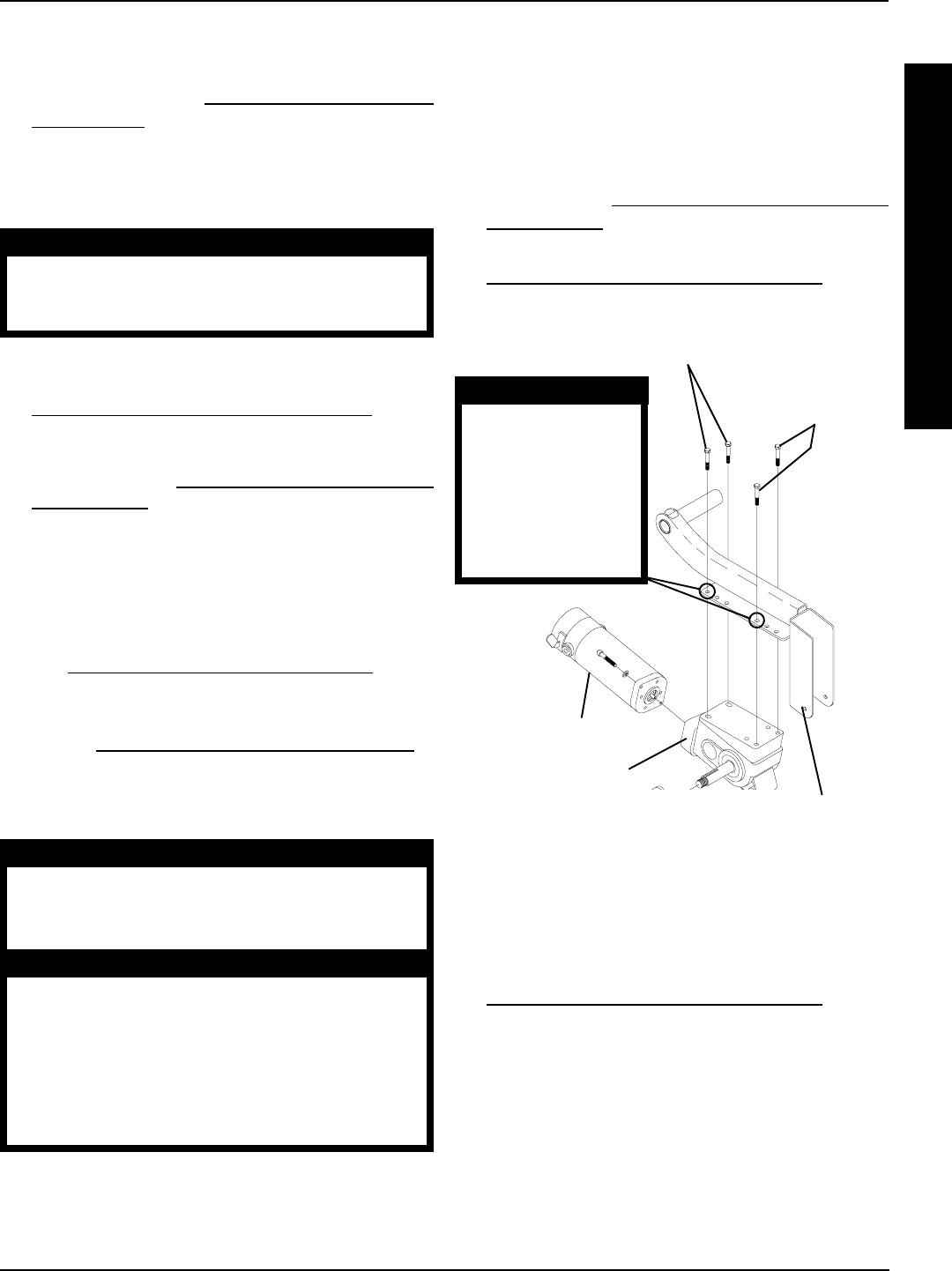
77
2. Count the number of exposed threads and repeat this
procedure for the opposite shock.
3. Proceed to STEP 9 in HEIGHT ADJUSTMENT OF
STABILIZERS in this procedure of the manual.
REMOVING/INSTALLING GEARBOX
(FIGURE 12)
CAUTION
Perform the following procedure in a des-
ignated work area to prevent damage to
flooring (carpeting, tile, etc.).
Removing
1. Remove the drive wheels from the wheelchair. Refer to
REMOVING/INSTALLING DRIVE WHEELS in PRO-
CEDURE 12 of this manual.
2. Remove the drive wheel hub from the existing gearbox
drive shaft. Refer to REMOVING/INSTALLING DRIVE
WHEEL HUBS in PROCEDURE 12 of this manual.
NOTE: Note the mounting position of gearbox to the sus-
pension arm before gearbox disassembly.
3. Remove the four (4) mounting screws that secure the
motor/gearbox to the suspension arm.
4. If necessary, remove existing motor from gearbox. Re-
fer to REMOVING/INSTALLING THE MOTOR in PRO-
CEDURE 12 of this manual.
5. If necessary, install existing motor onto NEW gearbox.
Refer to REMOVING/INSTALLING THE MOTOR in
PROCEDURE 12 of this manual.
Installing
WARNING
When reinstalling the gearbox ALWAYS use
the mounting holes furthest back on the sus-
pension arm. DO NOT reposition the motors.
CAUTION
The FRONT mounting screws that secure the
gearbox to the suspension arm MUST be 5/
16-18 x 2-1/2-inches long and the REAR hex
screws that secure the gearbox to the sus-
pension arm MUST be 5/16-18 x 1-1/4-inches
long. Otherwise damage to the gearbox
casting can result.
1. Position the NEW gearbox with the mounting holes fur-
thest back on the suspension arm.
2. When reassembling the gearbox to the suspension arm,
use Loctite 242 and torque mounting screws to 160-
inch pounds.
NOTE: Replace any parts that show signs of wear or dam-
age.
3. Reinstall the drive wheel hub to the new gearbox drive
shaft. Refer to REMOVING/INSTALLING DRIVE
WHEEL HUBS in PROCEDURE 12 of this manual.
4. Reinstall the drive wheels onto the wheelchair. Refer to
REMOVING/INSTALLING DRIVE WHEELS in PRO-
CEDURE 12 of this manual.
FIGURE 12 - REMOVING/INSTALLING GEARBOX
5/16-18 x 2-1/2-inch
Mounting Screws
5/16-18 x 1-1/4-inch
Mounting Screws
Gearbox
Suspension Arm
Motor
WARNING
When reinstalling the
gearbox ALWAYS
use the mounting
holes furthest back
on the suspension
arm. DO NOT reposi-
tion the motors.
REPLACING SUSPENSION ARM
(FIGURE 13)
1. Remove the drive wheels from the wheelchair. Refer to
REMOVING/INSTALLING DRIVE WHEELS in PRO-
CEDURE 12 of this manual.
2. Perform one (1) of the following:
A. (GROUP 24) - Loosen the mounting screws that
secures the wiring harness and the battery sub-
frame to the base frame assembly.
B. (GROUP 22) - Loosen the two (2) mounting
screws that secures the rear of the battery tray to
the sub-frame assembly.
PROCEDURE 15MWD WHEELCHAIRS
M
W
D
W
H
E
E
L
C
H
A
I
R
S
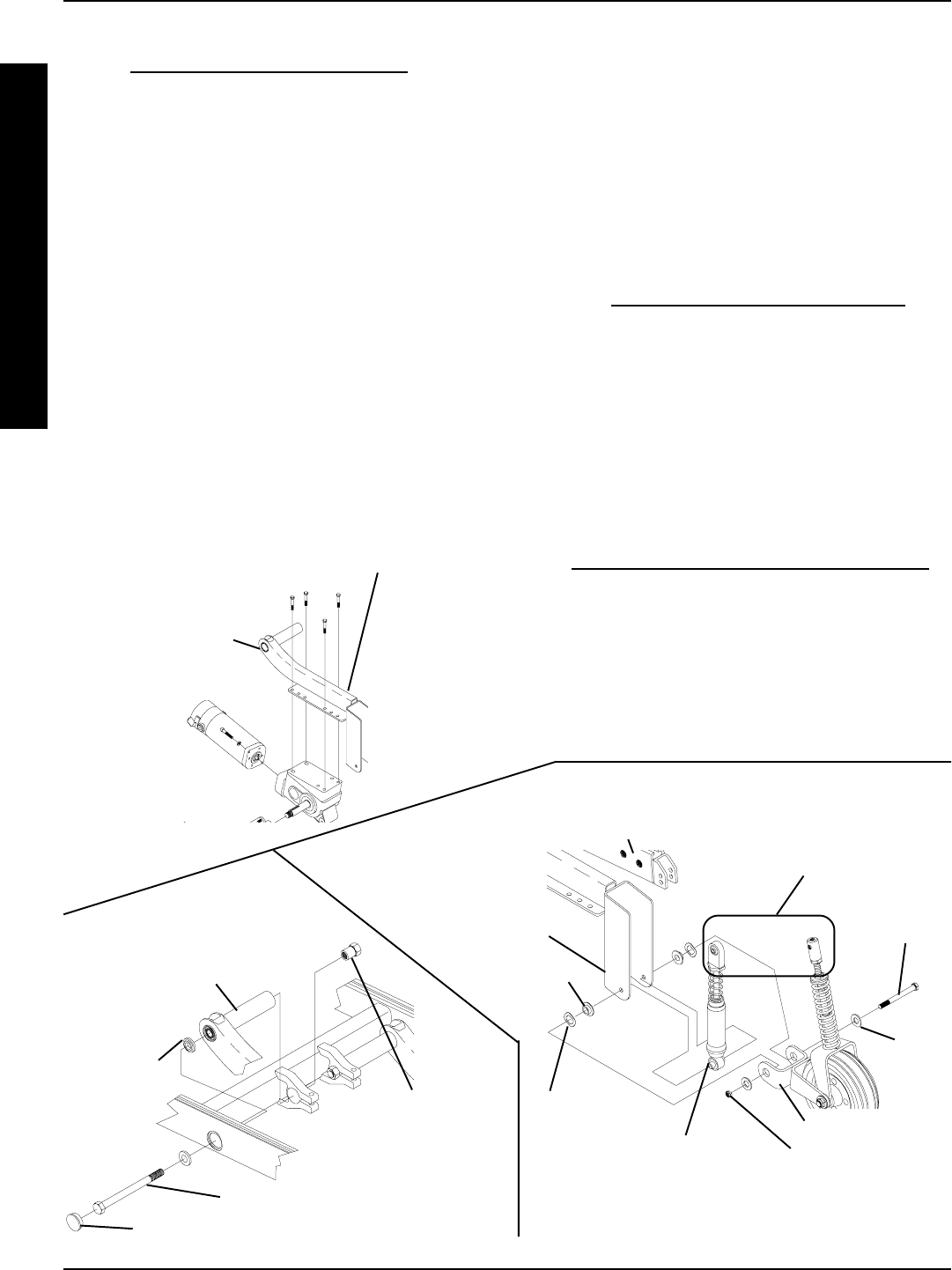
78
NOTE: When installing the tubular end of the NEW sus-
pension arm, the beveled washer MUST be placed on
the inside and outside of the base frame, with the bevels
facing each other.
10. Secure tubular end of the NEW suspension arm as-
sembly to base frame with existing mounting screw.
11. Torque suspension arm mounting screw (1/2 x 7-
inches) to 85 FOOT pounds (approximately 1,020-
inch pounds) and replace plug buttons.
12. Reinstall the gearbox onto the existing suspension arm.
Refer to REMOVING/INSTALLING GEARBOX in this
procedure of the manual.
13. Perform one (1) of the following:
A. (GROUP 24) - Tighten the mounting screws that
secures the wiring harness and the battery sub-
frame to the base frame assembly.
B. (GROUP 22) - tighten the two (2) mounting
screws that secures the rear of the battery tray to
the sub-frame assembly.
14. Reinstall the drive wheel onto the wheelchair. Refer
to REMOVING/INSTALLING DRIVE WHEELS in
PROCEDURE 12 of this manual.
15. Repeat STEPS 1-14 for the opposite side of the
wheelchair, if necessary.
FIGURE 13 - REPLACING SUSPENSION ARM
STEPS 4,8, AND 9
Plug Button (STEP 5)
Mounting Screw (STEPS 6,10)
Beveled
Washer
(STEPS
6,10)
Hex Nut
(STEPS 6,11)
Mounting
Screw
Base Frame
NOTE: Top of shock and stabi-
lizer exploded away for clarifica-
tion purposes only. Removal from
base frame is not required.
Flat
Washer
Locknut
Inner Link
Spacer
Spring Washer
Tubular End of
Suspension Arm
Bracket End of
Suspension Arm
Bracket End of Suspension Arm
Stabilizer Bracket
Bottom of Shock
Tubular End of
Suspension Arm
(STEPS 6,10)
3. Remove gearbox from the existing suspension arm. Re-
fer to REMOVING/INSTALLING GEARBOX in this proce-
dure of the manual.
4. Remove the mounting screw, two (2) flat washers,
two (2) spring washers, two (2) inner link spacers,
and locknut that secures the bracket end of the sus-
pension arm, the bottom of the shock, and stabilizer
bracket together.
5. Remove plug button from the middle of base frame.
6. Remove the mounting screw and the beveled wash-
ers that secures the tubular end of the suspension
arm assembly to the base frame.
7. Remove the suspension arm from the wheelchair.
8. Position bracket end of NEW suspension arm around
shock.
9. Thread existing mounting screw through stabilizer
bracket, bracket end of suspension arm, and bottom
of shock with mounting screw, two (2) flat washers,
two (2) spring washers, two (2) inner link spacers,
and locknut. See DETAIL A for proper hardware ori-
entation.
M
W
D
W
H
E
E
L
C
H
A
I
R
S
MWD WHEELCHAIRSPROCEDURE 15
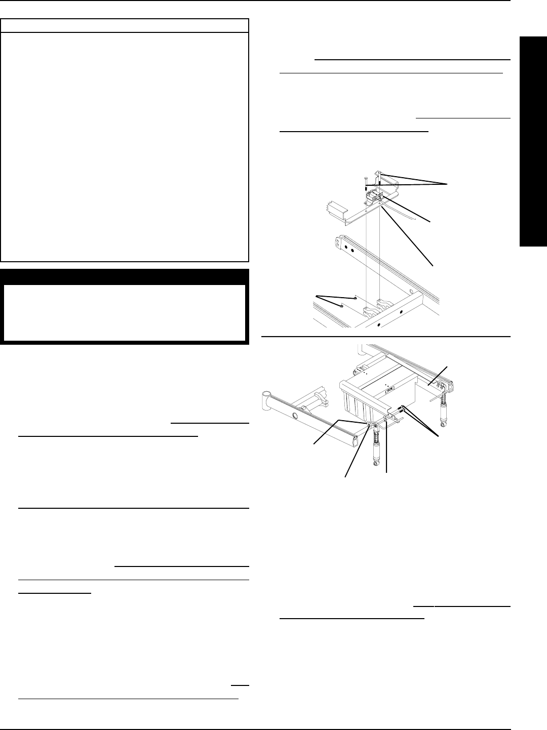
79
RWD WHEELCHAIRS PROCEDURE 16
R
W
D
W
H
E
E
L
C
H
A
I
R
S
This Procedure includes the following:
Removing/Installing Group 24 Battery Box Sub-Frame
Removing/Installing Group 22 Battery Box Tray
Converting Group 22 Batteries to Group 24 Batteries
Shock Replacement
Shock Spring Replacement
Rubber Element Replacement
Converting Torque and X Rubber Elements to Shocks
Anti-Tipper Wheel Replacement
Removing/Installing Gearbox
Adjusting Weight Distribution
Repositioning Motor/Gearbox Assembly
Repositioning Gearless/Brushless Motor
Replacing Suspension Arm for Wheelchairs with
Motor/Gearbox assembly
Replacing Suspension Arm for Wheelchairs with
Gearless/Brushless Motor
Removing/Installing the Anti-tip Assembly
FIGURE 1 - REMOVING/INSTALLING GROUP 24 BATTERY
BOX SUB-FRAME
Spacer
Battery Box
Retainer
Bar Retainer Clip
Battery Box
Sub-frame
Mounting
Screws
Wiring Harness
w/Bracket
Sub-Frame
Locknuts
REAR OF
CHAIR
REAR OF CHAIR
FRONT OF
CHAIR
Mounting
Screws
FRONT OF CHAIR
REMOVING/INSTALLING GROUP
22 BATTERY BOX TRAY (FIGURE 2)
Removing
1. Remove the battery box. Refer to INSTALLING/REMOV-
ING GROUP 24 BATTERY BOX in PROCEDURE 9
of this manual.
2. Remove the two (2) rear locknuts that secure the battery
box tray to battery mount brackets.
3. Remove the two (2) front bolts and locknuts that secure
the battery box tray to the base frame.
4. Remove the battery tray from the base frame.
REMOVING/INSTALLING GROUP 24
BATTERY BOX SUB-FRAME (FIGURE 1)
Removing
1. Remove the battery boxes. Refer to INSTALLING/RE-
MOVING GROUP 24 BATTERY BOXES in PROCE-
DURE 9 of this manual.
2. Remove the two (2) mounting screws and locknuts
that secure the wiring harness w/bracket and the rear
of the existing sub-frame to the base frame. Refer to
REMOVING/INSTALLING THE WIRING HARNESS
in PROCEDURE 10 of this manual.
3. Remove the four (4) mounting screws that secure the
shocks, retainer bar, spacers and retainer clips to the
base frame. Refer to REPLACING BATTERY BOX
RETAINER/RETAINER CLIP - GROUP 24 BATTERY
BASE FRAMES in PROCEDURE 11 of this manual.
4. Remove the existing sub-frame assembly.
Installing
1. Install the two (2) mounting screws and locknuts that
secure the wiring harness w/bracket and the back of
the NEW sub-frame to the base frame. Refer to RE-
MOVING/INSTALLING THE WIRING HARNESS in
PROCEDURE 10 of this manual. Use Loctite 242 and
torque mounting screws to 160-inch pounds.
2. Reinstall the four (4) mounting screws that secure the shocks,
retainer bar, spacers and retainer clips to the base frame.
Refer to REPLACING BATTERY BOX RETAINER/RE-
TAINER CLIP - GROUP 24 BATTERY BASE FRAMES in
PROCEDURE 11 of this manual. Use Loctite 242 and
torque mounting screws to 160-inch pounds.
3. Reinstall the battery boxes. Refer to INSTALLING/REMOV-
ING GROUP 24 BATTERY BOXES in PROCEDURE 9
of this manual. Use Loctite 242 and torque mounting screws
to 160-inch pounds.
WARNING
After ANY adjustments, repair or service and BE-
FORE use, make sure that all attaching hardware
is tightened securely - otherwise injury or dam-
age may result.
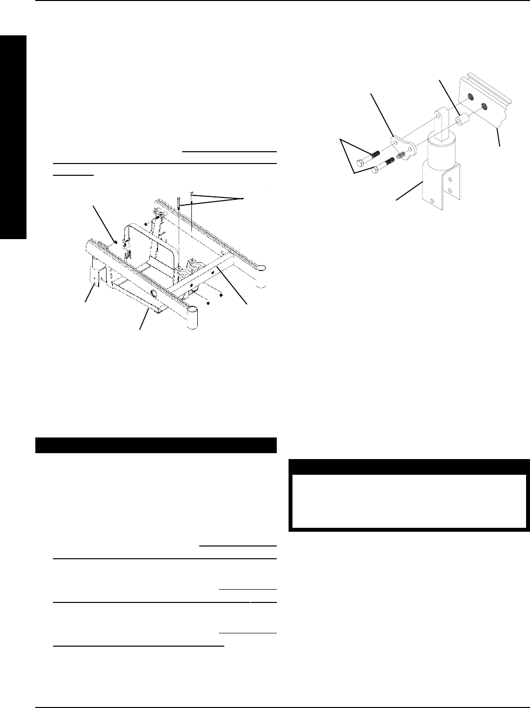
80
RWD WHEELCHAIRSPROCEDURE 16
R
W
D
W
H
E
E
L
C
H
A
I
R
S
Battery Tray
Locknuts Bolts
FIGURE 2 - REMOVING/INSTALLING GROUP 22
BATTERY BOX TRAY
*NOTE: Illustration depicts the rubber element. Battery Box
Tray removes in the same manner for shock assembly.
*Rubber
Element
4. Remove the four (4) mounting screws that secure
the battery mount brackets to the base frame.
5. Remove the battery mount brackets.
Spacer
Battery Mount
Bracket
*Rubber Element
(or Shock Assembly)
Mounting
Screws Base
Frame
FIGURE 3 - REMOVING GROUP 22 COMPONENTS
*NOTE: Illustration depicts rubber element. Battery
Mount Brackets remove in the same manner for the
shock assembly.
EQUIPMENT OPTION
CONVERTING GROUP 22 BATTERY
BOX TRAY TO GROUP 24 BATTERY
BOX SUB FRAMA ASSEMBLY
Removing Group 22 Components (FIGURE 3)
1. Remove the battery box. Refer to INSTALLING/RE-
MOVING GROUP 22 BATTERY BOX/BATTERIES
in PROCEDURE 9 of this manual.
2. Remove the battery box tray. Refer to REMOVING/
INSTALLING THE GROUP 22 BATTERY BOX TRAY
in this procedure of the manual.
3. Remove the wiring harness. Refer to REMOVING/
INSTALLING THE WIRING HARNESS in PROCE-
DURE 10 of this manual.
NOTE: The battery box tray and the battery mount brackets will
not be reused. Mounting screws and spacers will be reused.
Installing Group 24 Components (FIGURE 4)
1. Line up the mounting holes in the front of the NEW
battery box sub-frame and the NEW wiring harness
w/bracket with the mounting holes in the base frame
(FIGURE 5).
2. Install the two (2) mounting screws through the wiring
harness w/bracket, battery box sub-frame, and base
frame (FIGURE 5).
3. Install the locknuts onto mounting screws. Torque to
160-inch pounds (FIGURE 5).
WARNING
The Battery Box Retainer/Retainer Clip
MUST be fastened securely in place be-
fore using the wheelchair. Use Loctite 242
and torque to 160-inch pounds.
4. Position the retainer clip between the NEW battery box
sub-frame and the top of the rubber element or shock
assembly making sure the retainer clip mounting hole is
towards the bottom and the closed end of the clip is
against the battery box retainer bar (FIGURE 5).
NOTE: Make sure the closed end of the battery box re-
tainer clip is pointing up.
5. Install the mounting screw that secures the retainer
clip to the battery box sub-frame. Use Loctite® 242
and torque to 160-inch pounds (FIGURE 5).
6. Line up the NEW battery box retainer bar and spacers
with mounting holes in the base frame (FIGURE 5).
Base
Frame
Installing
1. Install battery tray onto base frame.
2. Secure the rear of the battery tray to battery mount
brackets with existing locknuts. Torque to 160-inch
pounds.
3. Secure the front of the battery tray to the base frame
with existing mounting screws and locknuts. Torque
to 160-inch pounds.
4. Reinstall the battery box. Refer to INSTALLING/REMOV-
ING BATTERY BOX - GROUP 22 BATTERY BASE
FRAMES in PROCEDURE 9 of this manual.
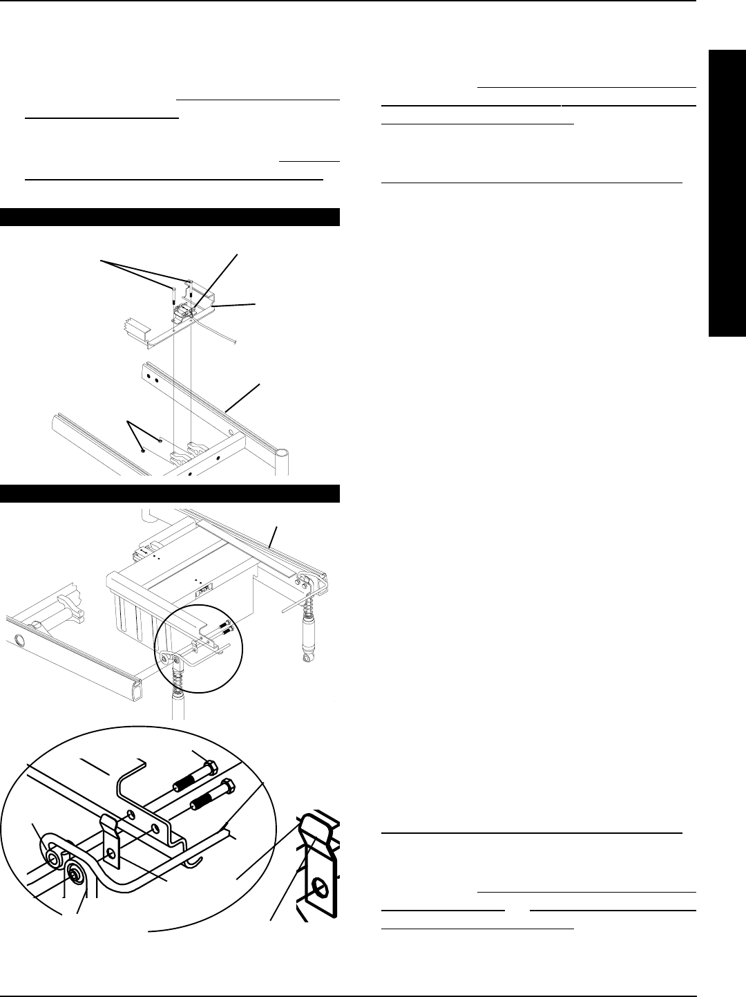
81
SHOCK REPLACEMENT (FIGURE 5)
1. Remove the group 22 battery box or group 24 battery
boxes. Refer to INSTALLING/REMOVING GROUP
22 BATTERY BOX or INSTALLING/REMOVING
GROUP 24 BATTERY BOXES in PROCEDURE 9
of this manual.
2. Remove the drive wheel from the wheel hub. Refer to
REMOVING/INSTALLING THE DRIVE WHEELS in
PROCEDURE 12 of this manual.
3. GROUP 24 BATTERIES ONLY - Loosen the hex
screw that secures the battery box retainer bar to the
base frame.
4. Remove the mounting screw that secures the top of
the shock to the base frame.
5. Remove the mounting screw and locknut from the bot-
tom of the suspension arm.
6. Remove the shock from the base frame.
7. Install the NEW shock.
8. Perform one (1) of the following sections:
A. GROUP 24 BATTERIES -
●Position retainer clip between shock and bat-
tery box sub-frame making sure the retainer clip
mounting hole is towards the bottom and the
closed end of clip is against battery box retainer
bar.
●Secure the top of shock and retainer clip
to base frame. Apply Loctite 242 and torque
to 160-inch pounds.
●Apply Loctite 242 and torque the hex screw
that secures the battery box retainer bar to
the base frame to 160-inch pounds.
B. GROUP 22 BATTERIES - Secure the top of
shock to base frame. Apply Loctite 242 and
torque to 160-inch pounds.
9. Secure the bottom of the new shock to the sus-
pension arm with the existing mounting screw and
locknut. Apply Loctite 242 and torque to 160-inch
pounds.
10. Install the drive wheel from the wheel hub. Refer to
REMOVING/INSTALLING THE DRIVE WHEELS in
PROCEDURE 12 of this manual.
11. Remove the group 22 battery box or group 24 battery
boxes. Refer to INSTALLING/REMOVING GROUP
22 BATTERY BOX or INSTALLING/REMOVING
GROUP 24 BATTERY BOXES in PROCEDURE 9
of this manual.
STEPS 1 - 3
STEPS 4 - 7
Spacer
Battery Box
Retainer
Bar
Mounting Screws
Retainer
Clip
REAR OF
CHAIR
FRONT OF
CHAIR
Battery Box
FRONT OF
CHAIR
REAR OF
CHAIR
Wiring Harness
w/Bracket
Mounting
Screws
Battery Box
Sub-Frame
Base
Frame
Locknuts
7. Reinstall the mounting screws that secure the bat-
tery box retainer bar to the base frame. Use Loctite
242 and torque to 160-inch pounds (FIGURE 5).
8. Perform STEPS 2-7 of REMOVING/INSTALLING
THE WIRING HARNESS in PROCEDURE 10 of this
manual to complete the wiring harness installation.
9. Install the group 24 battery boxes. Refer to INSTALL-
ING/REMOVING GROUP 24 BATTERY BOXES in
PROCEDURE 9 of this manual.
Closed End
RWD WHEELCHAIRS PROCEDURE 16
R
W
D
W
H
E
E
L
C
H
A
I
R
S
Shock Assembly
(or Rubber Element)
FIGURE 4 -INSTALLING GROUP 24 COMPONENTS
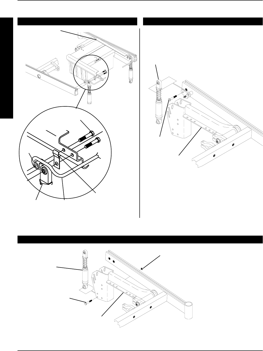
82
Battery Box
Sub-frame
REAR OF
CHAIR
FRONT OF
CHAIR
Spacer
Mounting Screw
(LOOSEN)
Retainer Clip
(Closed End)
GROUP 24 BATTERIES GROUP 22 BATTERIES
Mounting
Screw
Shock
Mounting
Screw
Locknut
Suspension
Arm
FIGURE 5 - SHOCK REPLACEMENT
Top of
Shock
Battery Box
Retainer
Bar
TOP OF SHOCK
BOTTOM OF SHOCK
GROUP 22 AND GROUP 24 BATTERIES
NOTE: Suspension arm for conventional motor shown.
Shock removes in the same manner for gearless/
brushless motor.
NOTE: Suspension arm shown is for conventional motors. Shock removes in the same manner for gearless/
brushless motor.
Shock
Suspension
Arm
RWD WHEELCHAIRSPROCEDURE 16
R
W
D
W
H
E
E
L
C
H
A
I
R
S
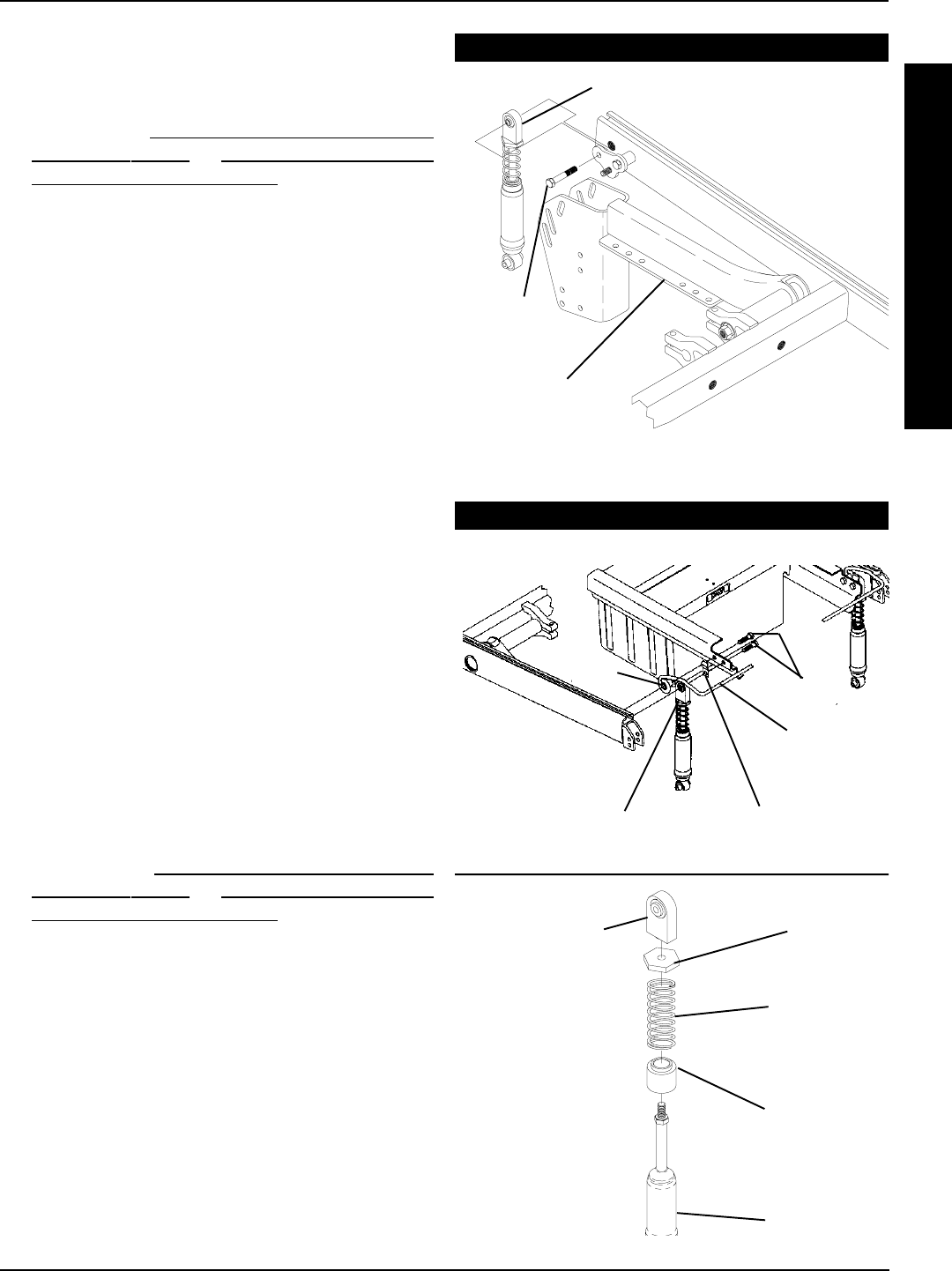
83
SHOCK SPRING REPLACEMENT
(FIGURE 6)
1. Remove the group 22 battery box or group 24 battery
boxes. Refer to INSTALLING/REMOVING GROUP
22 BATTERY BOX or INSTALLING/REMOVING
GROUP 24 BATTERY BOXES in PROCEDURE 9
of this manual.
2. GROUP 24 BATTERIES ONLY - Loosen the mount-
ing screw that secures the battery box retainer bar to the
base frame.
3. Remove the mounting screw that secures the top of
the shock to the suspension arm.
4. Swing the top of the shock rearward.
5. Hold the spring retainer and turn the shock eyelet as-
sembly counterclockwise to unthread it from the shock.
6. Remove the spring retainer and spring.
7. Place the NEW spring onto the shock.
8. Reinstall the shock eyelet assembly and the spring re-
tainer onto the NEW spring.
9. While holding the spring retainer, torque the shock eyelet
assembly to 245-inch pounds.
10. Position the retainer clip between the shock and the bat-
tery box sub-frame making sure the retainer clip mount-
ing hole is towards the bottom and the closed end of the
clip is against the battery box retainer.
11. Secure top of shock and retainer clip to base frame.
Apply Loctite 242 and torque to 160-inch pounds.
12. GROUP 24 BATTERIES ONLY - Apply Loctite 242
and torque the hex screw that secures the battery box
retainer bar to the base frame to 160-inch pounds.
13. Reinstall the group 22 battery box or group 24 battery
boxes. Refer to INSTALLING/REMOVING GROUP
22 BATTERY BOX or INSTALLING/REMOVING
GROUP 24 BATTERY BOXES in PROCEDURE 9
of this manual.
Battery Box
Retainer
Bar
Hex
Screws
Spacer
FIGURE 6 - SHOCK SPRING REPLACEMENT
Shock Eyelet
Assembly
Retainer Clip
Shock Eyelet
Assembly
Spring
Retainer
Shock
Spring
Spring
Base
Shock
RWD WHEELCHAIRS PROCEDURE 16
R
W
D
W
H
E
E
L
C
H
A
I
R
S
GROUP 22 BATTERIES
NOTE: Shock exploded away for clarity. There is no
need to remove shock from suspension arm.
Suspension
Arm
Mounting
Screw
Shock
GROUP 24 BATTERIES
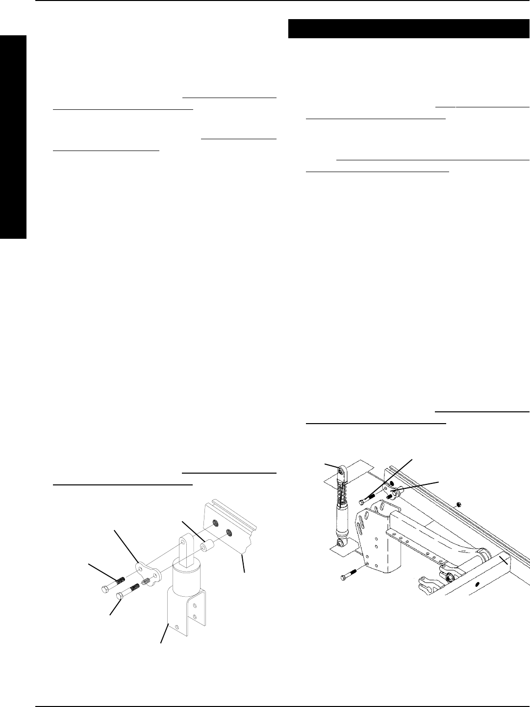
84
Spacer
Battery Mount
Bracket
Rubber Element
Mounting
Screw
Base
Frame
FIGURE 7 - RUBBER ELEMENT REPLACEMENT
Mounting Screw
(LOOSEN)
EQUIPMENT OPTION
CONVERTING TORQUE AND X
RUBBER ELEMENTS TO ARROW
SHOCKS (FIGURE 8)
1. Remove the battery box. Refer to INSTALLING/REMOV-
ING GROUP 22 BATTERY BOX in PROCEDURE 9
of this manual.
2. Remove the existing Torque and X rubber element. Re-
fer to RUBBER ELEMENT REPLACEMENT -
TORQUE AND X BASE FRAMES in this procedure of
the manual.
3. Line up the bottom of the new Storm Arrow shock with
the BOTTOM hole in the rubber element mount plate.
4. Install the new hex screw and locknut through the bot-
tom hole of the mount bracket and shock. Torque to
160-inch pounds.
NOTE: The original hardware that secured the BOTTOM of
the Torque and X rubber element to the shock mount bracket
will not be used with this option. Keep for future use.
5. Reinstall the hex screw that secures the top of the shock
assembly and battery mount bracket to the base frame.
Use Loctite 242 and torque to 160-inch pounds.
6. Torque the hex screw that secures the battery mount
bracket to the base frame to 160-inch pounds.
7. Reinstall the battery box tray onto the battery mount
bracket and torque the locknut to 160-inch pounds.
8. Reinstall the battery box. Refer to INSTALLING/REMOV-
ING GROUP 22 BATTERY BOX in PROCEDURE 9
of this manual.
Battery Mount
Bracket
Shock Hex Screw
FIGURE 8 - CONVERTING TORQUE AND X RUBBER
ELEMENTS TO ARROW SHOCKS
RWD WHEELCHAIRSPROCEDURE 16
R
W
D
W
H
E
E
L
C
H
A
I
R
S
RUBBER ELEMENT REPLACEMENT
(FIGURE 7)
NOTE: Rubber elements are only found on Storm
Torque and Storm X wheelchairs.
1. Remove the battery box. Refer to INSTALLING/REMOV-
ING GROUP 22 BATTERY BOX in PROCEDURE 9
of this manual.
2. Remove the battery box tray. Refer to REMOVING THE
BATTERY BOX TRAY in this procedure of the
manual.
3. Loosen the mounting screw that secures the battery
mount bracket to the base frame, but do not remove.
4. Remove the mounting screw that secures the top of
the rubber element and battery mount bracket to the
base frame.
6. Remove the three (3) mounting screws and locknuts
that secure the bottom of the rubber element to the rub-
ber element mount bracket.
7. Remove the existing rubber element and install the new
rubber element.
8. Resecure the bottom of the rubber element to the rub-
ber element mount bracket with the existing three (3)
mounting screws. Use Loctite 242 and torque to 160-
inch pounds.
9. Reinstall the hex screw that secures the top of the rub-
ber element and battery mount bracket to the base frame.
Use Loctite 242 and torque to 160-inch pounds.
10. Torque the hex screw that secures the battery mount
bracket to the base frame to 160-inch pounds.
11. Reinstall the battery box tray onto the hanger bracket
and torque the locknut to 160-inch pounds.
12. Reinstall the battery box. Refer to INSTALLING/REMOV-
ING GROUP 22 BATTERY BOX in PROCEDURE 9
of this manual.
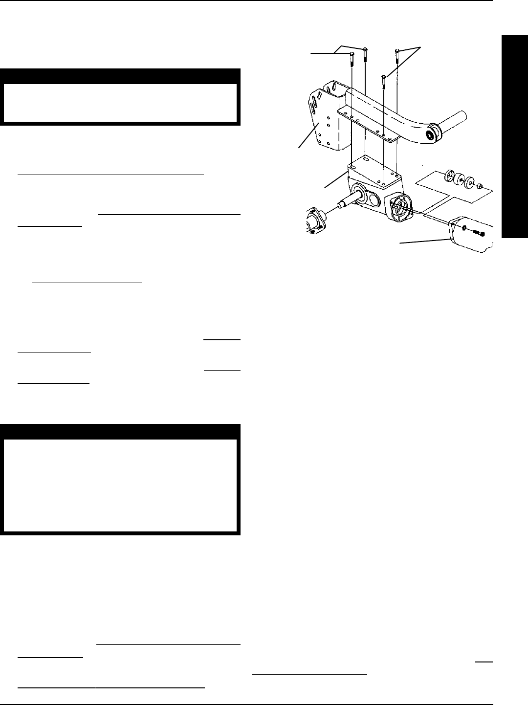
85
REMOVING/INSTALLING
GEARBOX
(FIGURE 10)
CAUTION
Perform the following procedure in a des-
ignated work area to prevent damage to
flooring (carpeting, tile, etc.).
Removing
1. Remove the drive wheels from the wheelchair. Refer to
REMOVING/INSTALLING DRIVE WHEELS in PRO-
CEDURE 12 of this manual.
2. Remove the drive wheel hub from the existing gearbox
drive shaft. Refer to REMOVING/INSTALLING DRIVE
WHEEL HUBS in PROCEDURE 12 of this manual.
NOTE: Note mounting position of gearbox to suspension
arm before disassembly.
NOTE: To reposition the gearbox on the suspension arm,
refer to WEIGHT DISTRIBUTION in this procedure of the
manual.
3. Remove the four (4) hex screws that secure the existing
motor/gearbox to the suspension arm.
4. Remove existing motor from gearbox. Refer to MOTOR
REPLACEMENT in PROCEDURE 12 of this manual.
5. Install existing motor onto new gearbox. Refer to MOTOR
REPLACEMENT in PROCEDURE 12 of this manual.
Installing
CAUTION
The REAR hex screws that secure the gear-
box to the suspension arm MUST be 5/16-
18 x 2-1/2-inches long and the FRONT hex
screws that secure the gearbox to the sus-
pension arm MUST be 5/16-18 x 1-1/4-inches
long. Otherwise damage to the gearbox
casting can result.
1. Position NEW gearbox with noted mounting holes.
2. When reassembling gearbox to suspension arm, use
Loctite 242 and torque hex screws to 160-inch pounds.
NOTE: Replace any parts that show signs of wear or dam-
age.
3. Reinstall the drive wheel hub to the new gearbox
driveshaft. Refer to REMOVING/INSTALLING DRIVE
WHEEL HUBS in PROCEDURE 12 of this manual.
4. Reinstall the drive wheels onto the wheelchair. Refer to
REMOVING/INSTALLING DRIVE WHEELS in PRO-
CEDURE 12 of this manual.
5/16-18 x
1-1/4-inch
Hex
Screws
Gearbox
Suspension
Arm
FIGURE 10 - REMOVING/INSTALLING GEARBOX
Motor
5/16-18 x
2-1/2-inch
Hex
Screws
RWD WHEELCHAIRS PROCEDURE 16
R
W
D
W
H
E
E
L
C
H
A
I
R
S
ADJUSTING WEIGHT
DISTRIBUTION (FIGURE 11)
NOTE: Seat mount plates and seat support brackets al-
low the seat frame to be repositioned along the base frame.
The range is determined by position of the seat stop
screws. The front seat stop screw is positioned at 4-inches
and the rear seat stop screw is positioned at 10-inches.
Both seat stop screw positions are measured from the
front of the base frame.
NOTE: The position of the seat support brackets is factory
set at 7-inches, this measured from the front of the base
frame to the front of the seat support bracket. This will put
about 70% of the total weight of the chair and user over the
large wheels. However, this setting may not be the most de-
sirable in terms of maneuverability, front rigging clearance
and comfort for the user.
Adjustment Options
NOTE: This section will provide the user with some knowl-
edge of what to expect if the following adjustments are made.
1. Moving the seat forward.
Advantage: This adjustment allows more clear-
ance for front riggings and a more stable
feel for the user.
Disadvantage: More weight is put on front casters and
makes turning more difficult.
NOTE: This option can also be accomplished by moving
the motor backward on the suspension arm. Refer to RE-
POSITIONING GEARBOX in this procedure of the manual.
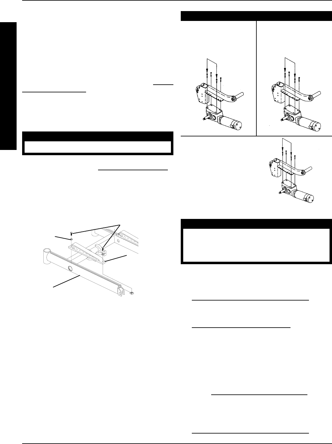
86
Washer
Base
Frame
FIGURE 11 - ADJUSTING WEIGHT DISTRIBUTION
Seat Support
Bracket
REPOSITIONING THE MOTOR/
GEARBOX (FIGURE 12)
NOTE: The motor/gearbox assembly can be repositioned to
lengthen or shorten the wheelbase by 2-inches in 1-inch in-
crements.
STANDARD POSITION - LENGTHENS the wheelbase and
gives you the most stability and standard maneuverability.
1 - INCH FORWARD - CENTERS the wheelbase and gives
you standard stability and maneuverability.
2 - INCH FORWARD - SHORTENS the wheelbase and in-
creases maneuverability and distributes additional weight on
rear wheels.
FIGURE 12 - REPOSITIONING MOTOR/GEARBOX
Standard -
Approximately 65% of
weight over rear
wheels
1 - Inch Forward -
Approximately 70% of
weight over rear
wheels
2 - Inch Forward -
Approximately 75% of
weight over rear
wheels
Mounting Screws
MOTOR/GEARBOX ASSEMBLY
2. Moving the seat rearward.
Advantage: Makes turning easier and provide bet-
ter traction for the large wheels.
Disadvantage: This adjustment, however, allows less
clearance for front riggings and the user
will experience more engagement of
the anti-tippers.
NOTE: This option can also be accomplished by moving
the motor forward on the suspension arm. Refer to REPO-
SITIONING GEARBOX in this procedure of the manual.
Adjusting Weight Distribution Procedure
1. Loosen the four (4) mounting screws that secure the
seat support brackets to the base frame.
WARNING
DO NOT adjust seat beyond limit stops.
2. Adjust seat forward or back to the position determined
from the previous section ADJUSTMENT OPTIONS.
3. Retighten the four (4) mounting screws securing the
seat support brackets to the base frame.
4. Test wheelchair maneuverability, comfort, and handling.
5. Repeat STEPS 1-4 for further adjustment, if necessary.
RWD WHEELCHAIRSPROCEDURE 16
R
W
D
W
H
E
E
L
C
H
A
I
R
S
WARNING
When using a recliner/high back van seat,
the motor/gearbox or motor MUST use most
REARWARD mounting holes on the suspen-
sion arm assembly.
1. Determine the desired position for the gearbox on the
wheelchair.
2. Remove the drive wheels from the wheelchair. Refer to
REMOVING/INSTALLING DRIVE WHEELS in PRO-
CEDURE 12 of this manual.
3. Remove gearbox from the suspension arm. Refer to
REMOVING/INSTALLING GEARBOX in this procedure
of the manual.
4. Move gearbox to the position determine in STEP 1.
NOTE: If the wheelchair is equipped with 9-inch casters on a
standard or heavy duty base, the 2-inch forward position CAN
NOT be utilized.
5. Reinstall the gearbox onto the existing suspension arm.
Refer to REMOVING/INSTALLING GEARBOX in this pro-
cedure of the manual.
6. Repeat STEPS 3-5 for opposite side of the wheelchair.
7. Reinstall the drive wheel onto the wheelchair. Refer to
REMOVING/INSTALLING DRIVE WHEELS in PRO-
CEDURE 12 of this manual.
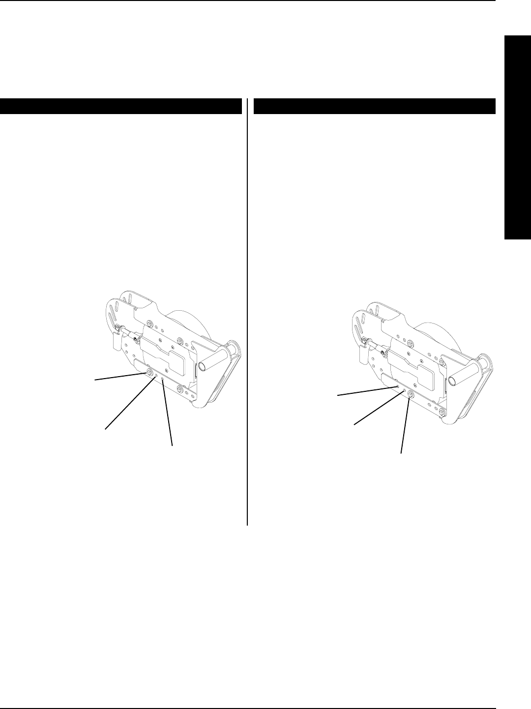
87
RWD WHEELCHAIRS PROCEDURE 16
R
W
D
W
H
E
E
L
C
H
A
I
R
S
Standard -
Approximately 65%
of weight over
rear wheels
1 - Inch Forward -
Approximately 70%
of weight over
rear wheels
2 - Inch Forward -
Approximately 75%
of weight over
rear wheels
REPOSITIONING THE GEARLESS/BRUSHLESS MOTOR (FIGURE 13,14)
Acceptable mounting positions for the gearless/brushless motor.
NOTE: The motor/gearbox assembly or gearless/brushless motor can be repositioned to lengthen or shorten the wheel-
base by 2-inches in 1-inch increments.
ARROW AND STORM X
NOTE: These mounting positions apply to the Arrow
and Storm X with fixed back or recliner and torque
with manual recline option
STANDARD POSITION - LENGTHENS the wheel-
base and gives you the most stability and standard
maneuverability.
1-INCH FORWARD - CENTERS the wheelbase and
gives you standard stability and maneuverability.
2-INCH FORWARD - SHORTENS the wheelbase and
increases maneuverability and distributes additional
weight on rear wheels.
TORQUE
NOTE:These mounting positions apply to the Torque
with fixed back.
STANDARD POSITION - SHORTENS the wheelbase and
increases maneuverability and distributes additional weight
on rear wheels.
1-INCH REARWARD - CENTERS the wheelbase and
gives you standard stability and maneuverability.
2-INCH REARWARD - LENGTHENS the wheelbase
and gives you the most stability and standard maneu-
verability.
1 - Inch Rearward -
Approximately 70%
of weight over
rear wheels
2 - Inch Rearward -
Approximately 65%
of weight over
rear wheels
Standard -
Approximately 75%
of weight over
rear wheels
FIGURE 13 - REPOSITIONING THE GEARLESS/BRUSHLESS MOTOR
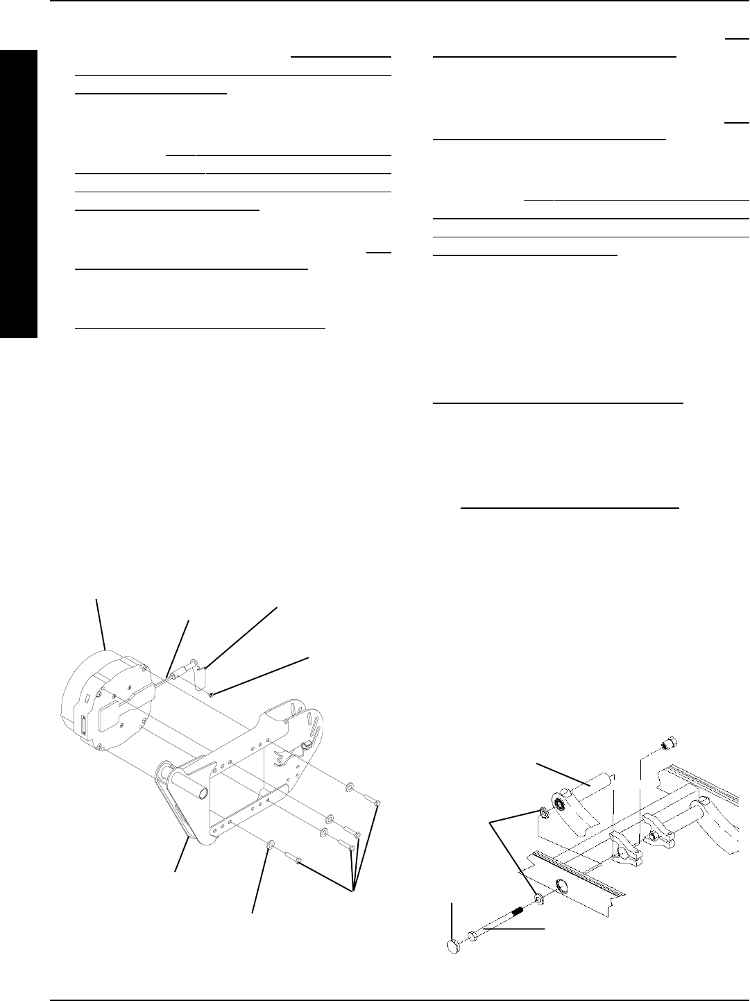
88
Suspension Arm Hex Screw
(1/2 x 7-inches)
FIGURE 15 - REPLACING SUSPENSION ARM FOR
WHEELCHAIRS WITH MOTOR/GEARBOX ASSEMBLY
Suspension Arm
Plug
Button
Beveled
Washers
REPLACING SUSPENSION ARM FOR
WHEELCHAIRS WITH MOTOR/
GEARBOX ASSEMBLY (FIGURE 15)
1. Remove the drive wheels from the wheelchair. Refer to
REMOVING/INSTALLING DRIVE WHEELS in PROCE-
DURE 12 of this manual.
2. Loosen the hex screws that secure wiring harness to
sub-frame assembly.
3. Remove gearbox from the existing suspension arm. Re-
fer to REMOVING/INSTALLING GEARBOX in this proce-
dure of the manual.
4. Remove plug buttons from the middle of the base frame.
5. Remove the hex screws and the beveled washers that
secure the suspension arm assembly to the base frame.
6. Remove existing suspension arm from the wheelchair.
NOTE: When installing the NEW suspension arm, the
beveled washers MUST be placed on the inside and out-
side of the base frame, with the bevels facing each other.
7. Install the NEW suspension arm assembly onto the
base frame.
1. Determine the desired mounting position of the gear-
less/brushless motor. Refer to ACCEPTABLE
MOUNTING POSITIONS FOR THE GEARLESS/
BRUSHLESS MOTOR in this procedure of the
manual.
2. Remove the group 22 battery box or group 24 battery
boxes. Refer to INSTALLING/REMOVING BATTERY
BOX - GROUP 22 BATTERY BASE FRAMES or IN-
STALLING/REMOVING BATTERY BOXES - GROUP
24 BATTERY BASE FRAMES in PROCEDURE 9 of
this manual.
3. If necessary, remove the battery box tray. Refer to RE-
MOVING THE BATTERY BOX TRAY in this proce-
dure of the manual.
4. Remove the drive wheel from the wheelchair. Refer to
REMOVING/INSTALLING DRIVE WHEELS in PROCE-
DURE 12 of this manual.
5. Loosen the adjustment screw that secures the motor
release handle to the brake release shaft.
6. Remove the four (4) mounting screws and washers
that secure the motor to the suspension arm.
7. Slide the motor forward or backward to the desired
mounting position.
8. Secure the motor to the mounting position determined
in STEP 1 and secure with the four (4) existing mount-
ing screws and washers. Torque to 13 foot/pounds.
9. Securely tighten adjustment screw.
FIGURE 14 - REPOSITIONING THE GEARLESS/
BRUSHLESS MOTOR
10. Reinstall the drive wheel to the wheelchair. Refer to RE-
MOVING/INSTALLING DRIVE WHEELS in PROCE-
DURE 12 of this manual.
11. Repeat STEPS 1-9 for opposite side of wheelchair.
12. If necessary, reinstall the battery box tray. Refer to RE-
MOVING THE BATTERY BOX TRAY in this proce-
dure of the manual.
13. Remove the group 22 battery box or group 24 battery
boxes. Refer to INSTALLING/REMOVING BATTERY
BOX - GROUP 22 BATTERY BASE FRAMES or IN-
STALLING/REMOVING BATTERY BOXES - GROUP
24 BATTERY BASE FRAMES in PROCEDURE 9 of
this manual.
Motor Release
Lever
Brake Release
Shaft
Adjustment
Screw
Mounting
Screws
Washer
Suspension Arm
Motor
RWD WHEELCHAIRSPROCEDURE 16
R
W
D
W
H
E
E
L
C
H
A
I
R
S
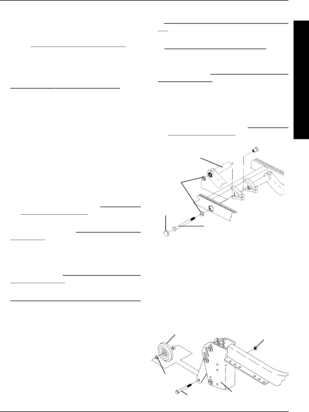
89
12. Install the shock onto the new suspension arm. Refer
to REMOVING/INSTALLING THE SHOCK ASSEM-
BLY in this procedure of the manual.
13. Install the motor onto the new suspension arm. Refer
to REMOVING/INSTALLING THE MOTOR in PRO-
CEDURE 12 of this manual.
14. Install anti-tip assembly onto the rear of the new sus-
pension arm. Refer to REMOVING/INSTALLING THE
ANTI-TIP ASSEMBLY in this procedure of the manual.
15. Perform one (1) of the following:
A. Remove the seating system. Refer to the seating
systems owners manual for removal/installation
instructions.
B. Remove the seat pan. Refer to REMOVING/IN-
STALLING THE SEAT PAN in PROCEDURE 6 of
this manual.
RWD WHEELCHAIRS PROCEDURE 16
R
W
D
W
H
E
E
L
C
H
A
I
R
S
8. Torque suspension arm hex screws (1/2 x 7-inches) to
85 FOOT pounds (approximately 1,020-inch pounds)
and replace plug buttons.
9. Reinstall the gearbox onto the existing suspension arm.
Refer to REMOVING/INSTALLING GEARBOX in this
procedure of the manual.
10. Tighten the hex screws that secure wiring harness to
sub-frame assembly securely.
11. Reinstall the drive wheel onto the wheelchair. Refer to
REMOVING/INSTALLING DRIVE WHEELS in PRO-
CEDURE 12 of this manual.
12. Repeat STEPS 1-12 for the opposite side of the wheel-
chair, if necessary.
REPLACING SUSPENSION ARM
FOR WHEELCHAIRS WITH
GEARLESS/BRUSHLESS MOTORS
(FIGURE 16)
1. Perform one (1) of the following:
A. Remove the seating system. Refer to the seating
systems owners manual for removal/installation
instructions.
B. Remove the seat pan. Refer to REMOVING/IN-
STALLING THE SEAT PAN in PROCEDURE 6 of
this manual.
2. Remove the motor. Refer to REMOVING/INSTALLING
THE MOTOR in PROCEDURE 12 of this manual.
3. Cut the tie-wrap(s) that secure the wiring harness/
charger cable to the suspension arm.
4. Remove the anti-tip assembly from the rear of the sus-
pension arm. Refer to REMOVING/INSTALLING THE
ANTI-TIP ASSEMBLY in this procedure of the manual.
5. Remove the shock from the suspension arm. Refer to
REMOVING/INSTALLING THE SHOCK ASSEMBLY
in this procedure of the manual.
6. Remove the plug buttons from the side of the base
frame.
7. Remove the mounting screw and beveled washers
that secure the front of the suspension arm to the base
frame.
8. Remove the existing suspension arm from the base
frame.
9. Install the new suspension arm onto the base frame.
10. Install mounting screw and beveled washers that se-
cure the front of the suspension arm to the base frame.
11. Install the plug buttons into the side of the base frame
Suspension Arm Hex Screw
(1/2 x 7-inches)
FIGURE 16 - REPLACING SUSPENSION ARM FOR
WHEELCHAIRS WITH GEARLESS/BRUSHLESS MOTOR
Suspension Arm
Plug
Button
Beveled
Washers
Anti-Tipper Wheel Locknut
ANTI-TIPPER WHEEL
REPLACEMENT (FIGURE 9)
1. Remove the locknuts, hex screws and spacers that
secure the anti-tipper wheels to the shock mount plates.
2. Replace anti-tipper wheel(s) and torque existing hard-
ware to 30-35-inch pounds. DO NOT overtighten.
Spacer
FIGURE 9 - ANTI-TIPPER WHEEL REPLACEMENT
Hex Screw Shock Mount Plates

90
REMOVING/INSTALLING THE
ANTI-TIP ASSEMBLY
Removing
1. Remove the mounting screw, washers, and spacers
that secure the top of the anti-tip bracket to the suspen-
sion arm.
2. Remove the mounting screw and locknut that secure
the extension spring in place.
3. Remove the mounting screw, washers, and spacers
that secure the bottom of the anti-tip bracket to the sus-
pension arm.
Installing
1. Align top mounting hole of anti-tip bracket with top mount-
ing slot in rear of suspension arm.
RWD WHEELCHAIRSPROCEDURE 16
R
W
D
W
H
E
E
L
C
H
A
I
R
S
Suspension
Arm
Anti-Tip
Bracket Spacers
Extension
Spring
Mounting
Screw
Locknut
Mounting
Screws
DO NOT use this mounting hole. This
mounting hole is used to secure the
shock assembly.
FIGURE 17 - REMOVING/INSTALLING THE ANTI-TIP ASSEMBLY
NOTE: Suspension arm shown is for gearless/brushless motor. The Anti-tip assembly removes/installs in the
same manner on the suspension arm used with the conventional motor/gearbox assembly.
Locknuts
Washers
Lower
Mounting
Hole
DO NOT
USE THIS
MOUNTING
HOLE
DO NOT
USE THIS
MOUNTING
SLOT
DO NOT
USE THIS
MOUNTING
HOLE
Lower
Mounting
Hole
2. Secure top of anti-tip bracket to suspension arm with
existing mounting screw, washers, spacers, and lock-
nut. Securely tighten.
3. Align lower mounting hole of the anti-tip mounting bracket
with the lower slot of the suspension arm.
4. Secure the anti-tip bracket to the suspension arm
with the existing mounting screw, washers, spac-
ers, and locknuts. Securely tighten.
5. Hook one end of the extension spring around
mounting screw.
6. Install mounting screw through lower mounting
hole in suspension arm, other end of extension
spring and opposite side of suspension arm. Se-
curely tighten with locknut.
Top
Mounting
Hole
Lower
Mounting
Slot
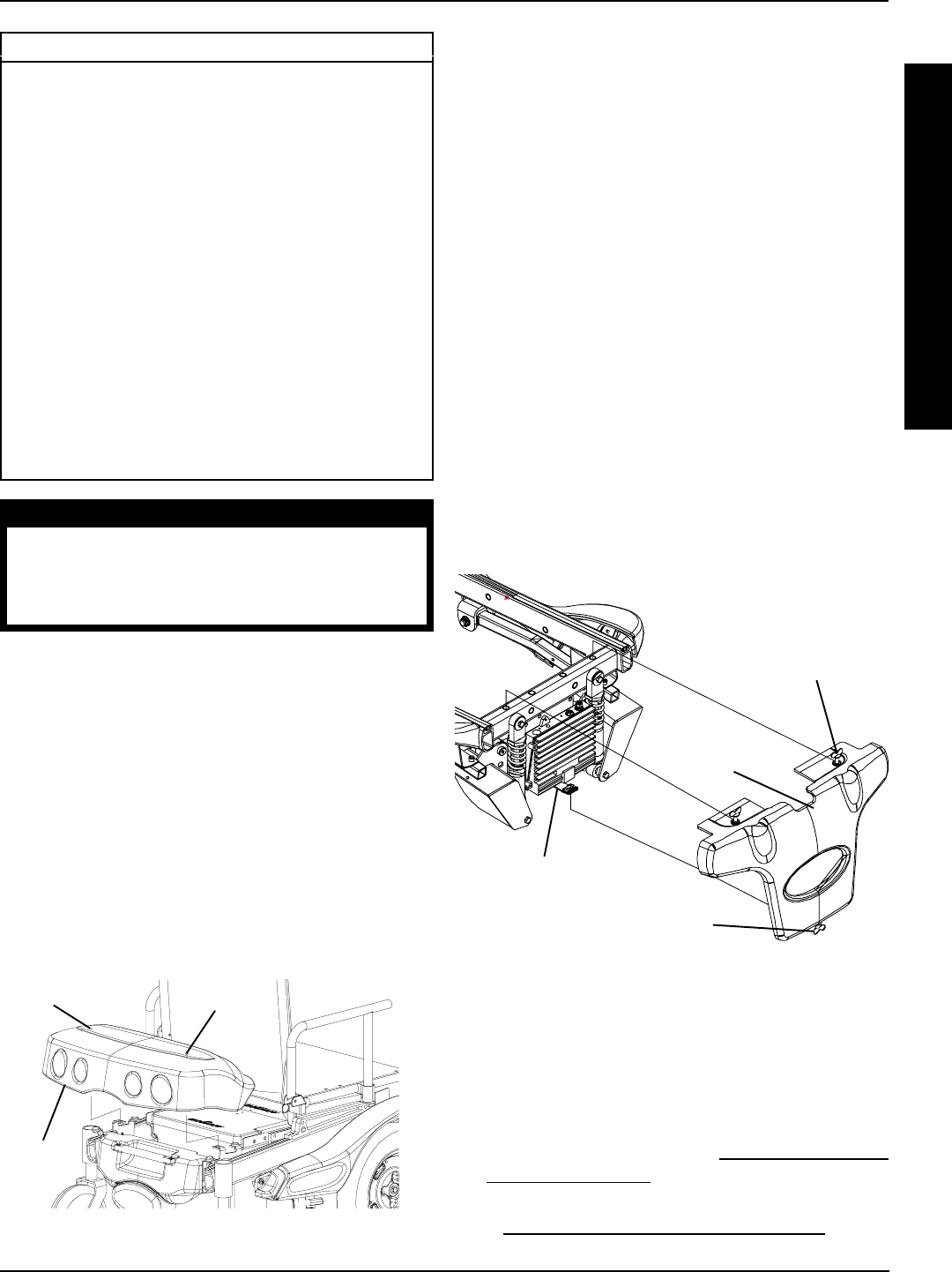
91
FWD WHEELCHAIRS PROCEDURE 17
F
W
D
W
H
E
E
L
C
H
A
I
R
S
This Procedure includes the following:
Removing/Installing Rear Shroud
Removing/Installing Front Shroud
Removing/Installing Side Shroud Assembly
Removing/Installing Counterweight
Replacing Group 24 Battery Box Sub-Frame
Removing/Installing Shocks
Shock Spring Replacement
Tie Rod Replacement
Removing/Installing Gearbox
Sensor Cable Assembly Replacement
Replacing Suspension Arm
Removing/Installing The Wiring Harness
Adjusting Weight Distribution
FIGURE 2 - REMOVING/INSTALLING FRONT
SHROUD
Front
Shroud
Wing Nut
Wing Nut
Mounting
Bracket
REMOVING/INSTALLING REAR
SHROUD (FIGURE 1)
Removing
1. Turn the two (2) wing nuts COUNTERCLOCKWISE
and lift up on the rear shroud.
Installing
1. Position the rear shroud on the wheelchair frame align-
ing the two (2) wing nuts with the mounting brackets.
2. Turn the two (2) wing nuts CLOCKWISE to secure
rear shroud in place.
Wing
Nut
Rear
Shroud
Wing
Nut
FIGURE 1 - REMOVING/INSTALLING REAR
SHROUD
REMOVING/INSTALLING FRONT
SHROUD (FIGURE 2)
Removing
1. Turn the two (2) wing nuts on the TOP of the front
shroud COUNTERCLOCKWISE.
2. Turn the wing nut on the BOTTOM of the front shroud
COUNTERCLOCKWISE and lift up on the front
shroud.
Installing
1. Position the front shroud on the wheelchair frame.
2. Align the wing nut on the BOTTOM of the front shroud
with the mounting bracket on the wheelchair frame.
3. Align the two (2) wing nuts on the TOP of the front
shroud with the mounting holes in the wheelchair frame.
4. Turn the wing nut on the BOTTOM of the front shroud
CLOCKWISE to secure front shroud in place.
5. Turn the two (2) wing nuts on the TOP of the front
shroud CLOCKWISE to secure front shroud in place.
WARNING
After ANY adjustments, repair or service
and BEFORE use, make sure that all at-
taching hardware is tightened securely -
otherwise injury or damage may result.
REMOVING/INSTALLING SIDE
SHROUD ASSEMBLY (FIGURE 3)
Removing
1. Remove the rear shroud. Refer to REMOVING/INSTALL-
ING REAR SHROUD in this procedure of the manual.
2. Remove the drive wheel from the wheelchair. Refer
to REMOVING/INSTALLING DRIVE WHEEL in PRO-
CEDURE 12 of this manual.
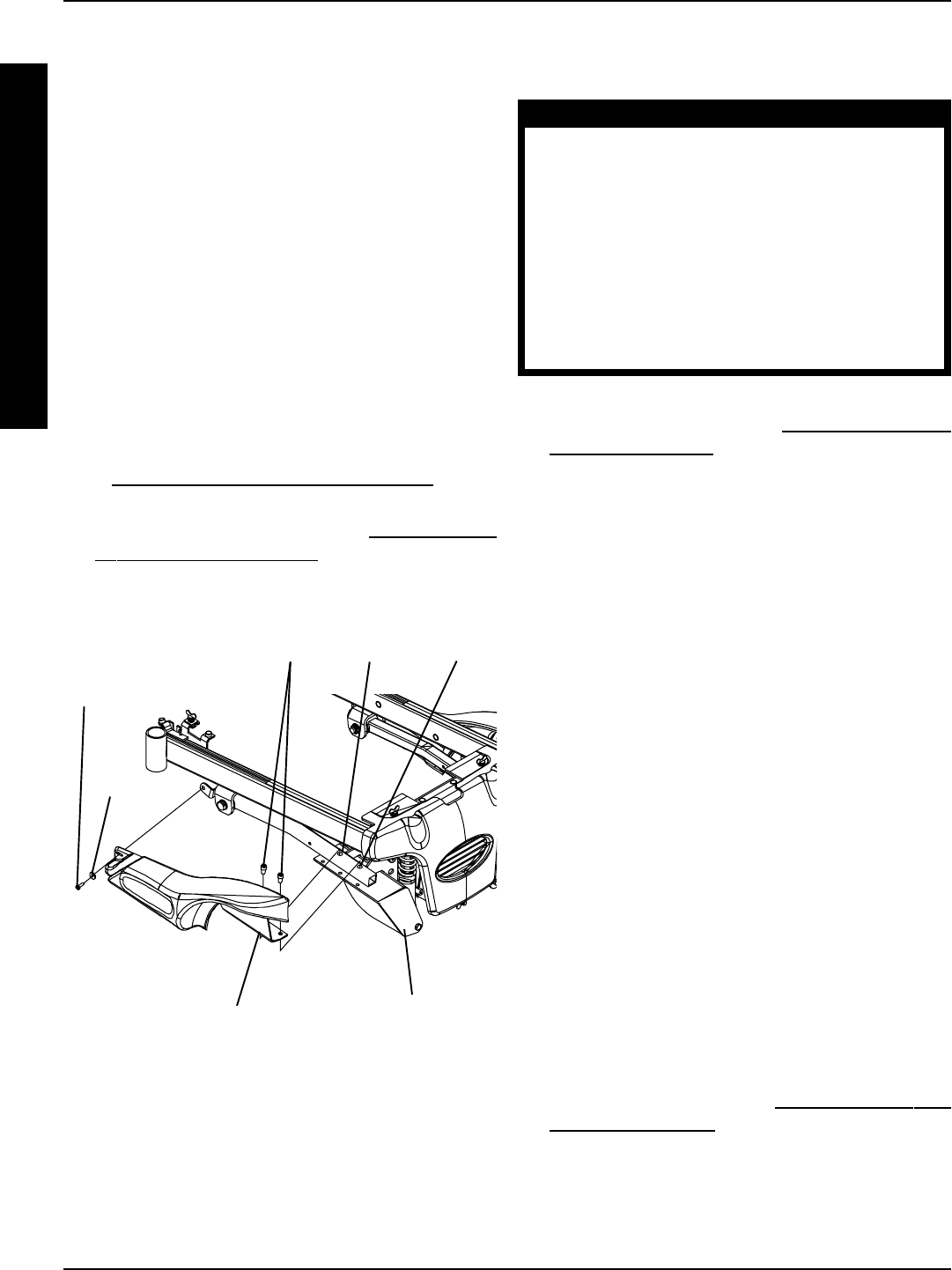
92
FWD WHEELCHAIRSPROCEDURE 17
F
W
D
W
H
E
E
L
C
H
A
I
R
S
3. Remove the two (2) socket screws that secure the
side shroud bracket to the suspension arm.
4. Remove the mounting screw and washer that se-
cures the REAR of the side shroud to the suspension
arm.
5. Remove the side shroud assembly.
Installing
1. Position the side shroud on the wheelchair frame.
2. Install the two (2) socket screws that secure the side
shroud bracket into the mounting holes of the sus-
pension arm. Securely tighten.
3. Install the mounting screw and washer that secures
the REAR of the side shroud to the suspension arm.
4. Repeat STEPS 1-3 for the opposite side shroud as-
sembly, if necessary.
5. Reinstall the drive wheel from the wheelchair. Refer
to REMOVING/INSTALLING DRIVE WHEEL in PRO-
CEDURE 12 of this manual.
6. Reinstall the rear shroud. Refer to REMOVING/IN-
STALLING REAR SHROUD in this procedure of the
manual.
FIGURE 3 - REMOVING/INSTALLING SIDE
SHROUD ASSEMBLY
Socket
Screws
Side Shroud Bracket
Mounting
Screw
Washer
Suspension Arm
REMOVING/INSTALLING
COUNTERWEIGHT (FIGURE 4)
WARNING
The sensor on the wheelchair should pre-
vent the wheelchair from operating with-
out the counterweight secured to the rear
of the wheelchair. If the wheelchair oper-
ates without the counterweight, DO NOT op-
erate the wheelchair. Have the wheelchair
serviced by a dealer or qualified technician.
The counterweight weighs 42 pounds. Use
proper lifting techniques (lift with your legs)
to avoid injury.
Removing
1. Remove the rear shroud. Refer to REMOVING/INSTALL-
ING REAR SHROUD in this procedure of the manual.
2. While using proper lifting techniques, use ONE hand
to firmly grasp the handle and the OTHER hand to
firmly grasp the OUTSIDE LOWER EDGE of the
counterweight.
3. Pull the outside lower edge toward you, releasing the
bottom shoulder screws on the counterweight from the
bottom slots in the mounting brackets.
4. Lift the counterweight up and remove the top shoulder
screws from the top slots in the mounting brackets.
Installing
1. While using proper lifting techniques, use ONE hand
to firmly grasp the handle and the OTHER hand to
firmly grasp the OUTSIDE LOWER EDGE of the
counterweight.
2. Hold the counterweight at an angle (DETAIL C) and
position the top shoulder screws into the top slots on the
mounting brackets.
3. Lower the counterweight down until the bottom shoulder
screws engage in the bottom slots on the mounting brack-
ets.
4. Push in the bottom rear of the counterweight to se-
cure the counterweight to the wheelchair until it locks
into place (DETAIL A).
5. Install the rear shroud. Refer to REMOVING/INSTALL-
ING REAR SHROUD in this procedure of the manual.
Front
Mounting
Hole
Rear
Mounting
Hole
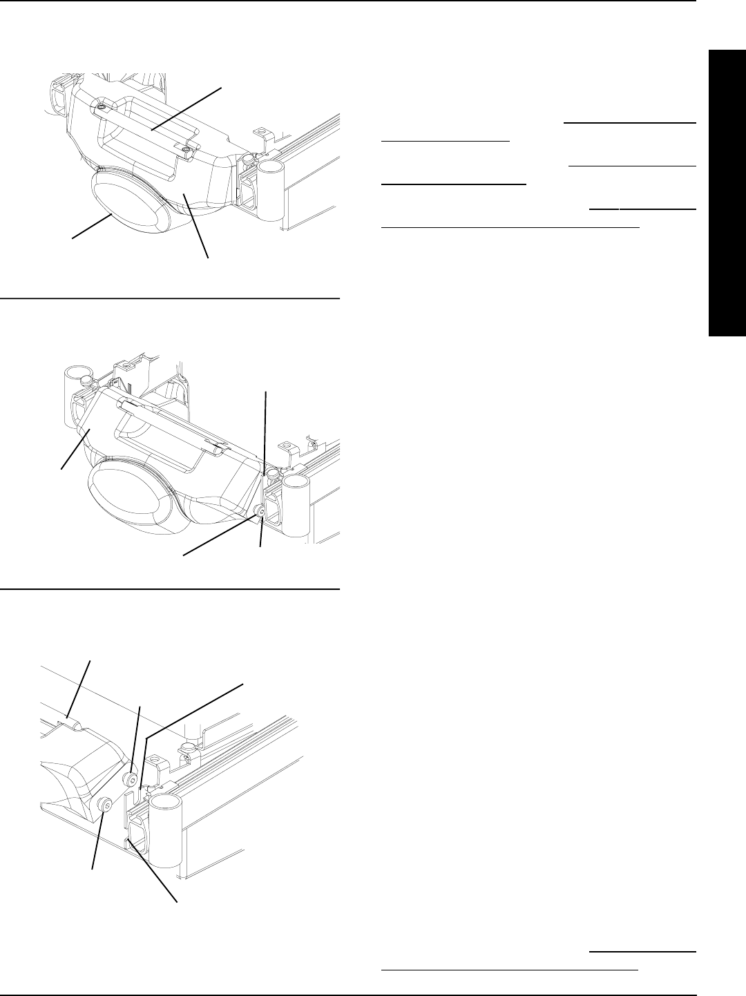
93
FWD WHEELCHAIRS PROCEDURE 17
F
W
D
W
H
E
E
L
C
H
A
I
R
S
FIGURE 4 - REMOVING/INSTALLING
COUNTERWEIGHT
Bottom Shoulder Screw
Bottom Slot in Mounting Bracket
Top Shoulder
Screw
Counterweight
DETAIL “C” - REMOVING - STEP 4;
INSTALLING - STEP 2
DETAIL “B” - REMOVING - STEP 3;
INSTALLING - STEPS 3, 4
DETAIL “A” - REMOVING - STEP 2;
INSTALLING - STEP 5
Outside
Lower Edge
Handle
Bottom Shoulder Screw
Mounting Bracket
Top Slot in
Mounting
Bracket
REPLACING GROUP 24 BATTERY
BOX SUB-FRAME (FIGURE 5)
Removing
1. Remove the rear shroud. Refer to REMOVING/INSTALL-
ING REAR SHROUD in this procedure of the manual.
2. Remove the counterweight. Refer to REMOVING/INSTALL-
ING COUNTERWEIGHT in this procedure of the manual.
3. Remove the battery boxes. Refer to INSTALLING/RE-
MOVING GROUP 24 BATTERY BOXES in PRO-
CEDURE 9 of this manual.
4. Cut tie wrap A, which secures the sensor cable AND
the LEFT motor cable to the battery box sub-frame.
5. Cut tie-wrap B, which secures the battery charger cable
AND the RIGHT motor cable to the battery box sub-frame.
6. Remove the two (2) mounting screws and locknuts
that secure the wiring harness w/bracket to the bat-
tery box sub-frame.
7. Remove the wiring harness w/bracket from the bat-
tery box sub-frame.
8. Remove the four (4) mounting screws and washers
that secure the battery box sub-frame to the mount-
ing brackets.
9. Remove the EXISTING sub-frame assembly.
10. Remove the four (4) mounting screws and wash-
ers that secure the two (2) mounting brackets to
the sub-frame.
11. Install the four (4) mounting screws and washers
that secure the two (2) NEW mounting brackets
to the sub-frame.
12. Install the four (4) mounting screws that secure the
NEW battery box sub-frame to the mounting brack-
ets. Use Loctite 242 and torque mounting screws to
156-inch pounds.
13. Install the two (2) mounting screws and locknuts that
secure the wiring harness w/bracket to the NEW bat-
tery box sub-frame. Use Loctite 242 and torque mount-
ing screws to 160-inch pounds.
14. Secure the sensor cable AND the LEFT motor cable
to the NEW battery box sub-frame using tie wrap A.
Refer to FIGURE 5 for tie wrap positioning.
15. Secure the battery charger cable AND the RIGHT
motor cable to the NEW battery box sub-frame using
tie wrap B. Refer to FIGURE 5 for tie wrap positioning.
16. Reinstall the battery boxes. Refer to INSTALLING/RE-
MOVING GROUP 24 BATTERY BOXES in PRO-
CEDURE 9 of this manual.
Counterweight
Counterweight
Bottom
Slot
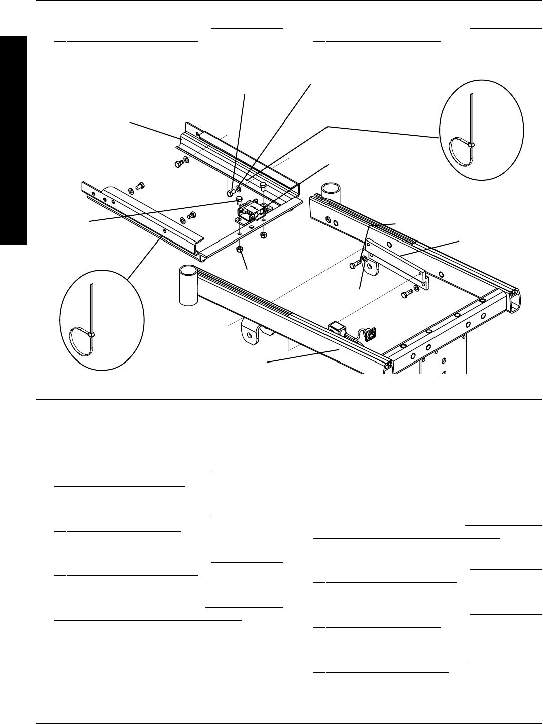
94
FWD WHEELCHAIRSPROCEDURE 17
F
W
D
W
H
E
E
L
C
H
A
I
R
S
FIGURE 5 - REMOVING/INSTALLING GROUP 24 BATTERY BOX SUB-FRAME
REAR OF
CHAIR
FRONT OF
CHAIR
Mounting
Screw
(STEPS 6
and 13)
Locknut
Wiring Harness
W/ Bracket
Battery Box
Sub-frame
Sub-Frame
Mounting Screw
(STEPS 8 and 12) Washer (STEP 8 and 12)
Position
Tie Wrap
A Here
REMOVING/INSTALLING SHOCKS
(FIGURE 6)
Removing
1. Remove the front shroud. Refer to REMOVING/IN-
STALLING FRONT SHROUD in this procedure of the
manual.
2. Remove the rear shroud. Refer to REMOVING/IN-
STALLING REAR SHROUD in this procedure of the
manual.
3. Remove the counterweight. Refer to REMOVING/IN-
STALLING COUNTERWEIGHT in this procedure of
the manual.
4. Remove the battery boxes. Refer to INSTALLING/RE-
MOVING GROUP 24 BATTERY BOXES in PRO-
CEDURE 9 of this manual.
5. Remove the mounting screw and washer that se-
cures the top of the EXISTING shock to the base frame.
6. Remove the mounting screw and locknut that secures
the bottom of the EXISTING shock to the suspension
arm.
7. Remove the EXISTING shock.
Position
Tie Wrap
B Here
Mounting
Bracket (Only
One (1) Shown
For Clarity)
17. Reinstall the counterweight. Refer to REMOVING/IN-
STALLING COUNTERWEIGHT in this procedure of
the manual.
18. Reinstall the rear shroud. Refer to REMOVING/IN-
STALLING REAR SHROUD in this procedure of the
manual.
Installing
1. Secure the top of the NEW shock to base frame us-
ing the existing washer and mounting screw. Apply
Loctite 242 and torque to 156-inch pounds.
2. Secure the bottom of the NEW shock to the suspen-
sion arm with the existing mounting screw and lock-
nut. Apply Loctite 242 and torque to 160-inch pounds.
3. Reinstall the battery boxes. Refer to INSTALLING/RE-
MOVING GROUP 24 BATTERY BOXES in PRO-
CEDURE 9 of this manual.
4. Reinstall the counterweight. Refer to REMOVING/IN-
STALLING COUNTERWEIGHT in this procedure of
the manual.
5. Reinstall the rear shroud. Refer to REMOVING/IN-
STALLING REAR SHROUD in this procedure of the
manual.
6. Reinstall the front shroud. Refer to REMOVING/IN-
STALLING FRONT SHROUD in this procedure of
the manual.
Mounting
Screw
(STEPS 10
and 11)
Washer
(STEP 10
and 11)

95
FWD WHEELCHAIRS PROCEDURE 17
F
W
D
W
H
E
E
L
C
H
A
I
R
S
SHOCK SPRING REPLACEMENT
(FIGURE 7)
1. Remove the shock. Refer to REMOVING/INSTALL-
ING SHOCKS in this procedure of this manual.
2. Hold the spring retainer and turn the shock eyelet as-
sembly counterclockwise to unthread it from the shock.
3. Remove the spring retainer and spring.
4. Place the NEW spring onto the shock.
5. Reinstall the shock eyelet assembly and the spring
retainer onto the NEW spring.
6. While holding the spring retainer, torque the shock
eyelet assembly to 245-inch pounds.
FIGURE 7 - SHOCK SPRING REPLACEMENT
Shock Eyelet
Assembly
Spring
Spring
Base
Shock
7. Secure top of shock and spring retainer to base frame.
Apply Loctite 242 and torque to 160-inch pounds.
8. Reinstall the shock. Refer to REMOVING/INSTALL-
ING SHOCKS in this procedure of this manual.
TIE ROD REPLACEMENT (FIGURE 8)
Removing
1. Remove the front shroud. Refer to REMOVING/INSTALL-
ING FRONT SHROUD in this procedure of the manual.
2. Remove the rear shroud. Refer to REMOVING/INSTALL-
ING REAR SHROUD in this procedure of the manual.
3. Remove the counterweight. Refer to REMOVING/IN-
STALLING COUNTERWEIGHT in this procedure of
the manual.
4. Remove the battery boxes. Refer to INSTALLING/RE-
MOVING GROUP 24 BATTERY BOXES in PRO-
CEDURE 9 of this manual.
5. Remove the shocks. Refer to REMOVING/INSTALL-
ING SHOCKS in this procedure of this manual.
6. Remove the MKIV controller. Refer to REMOVING/
INSTALLING MKIV CONTROLLER in PROCEDURE
13 of this manual.
7. Remove the locknut, small washer, larger washer and
mounting screw that secures the tie rod to the sus-
pension arm.
8. Remove the locknut, small washer, large washer and
mounting screw that secures the tie rod to the base frame.
9. Remove the tie rod from the wheelchair.
NOTE: In order to ensure that the replacement tie rod(s)
are adjusted properly, it is necessary to remove ALL
of the tie rods from the wheelchair and install both the
NEW and the EXISTING tie rods as described in the
section below.
10. Repeat STEPS 7-9 to remove the three (3) remain-
ing tie rods.
Adjusting/Installing
1. Before installing, adjust the collar on one (1) tie rod
until the length of the tie rod is approximately five (5)
inches (DETAIL A).
NOTE: The length of the tie-rod is measured from the
center of one eyelet to the center of the opposite eyelet.
NOTE: Turn the collar CLOCKWISE to shorten the tie
rod and COUNTER-CLOCKWISE to lengthen the tie rod.
2. Lock the collar on the tie rod into place by turning
the nut on the tie rod until it is FLUSH against the
collar (DETAIL A).
Locknut
Mounting Screw
Washer
Mounting Screw
FIGURE 6 - REMOVING/INSTALLING SHOCKS
Base Frame
Suspension Arm
Shock
Spring
Retainer
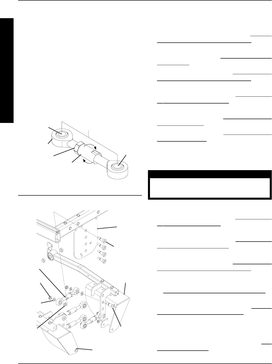
96
FWD WHEELCHAIRSPROCEDURE 17
F
W
D
W
H
E
E
L
C
H
A
I
R
S
REMOVING/INSTALLING
GEARBOX (FIGURE 9)
CAUTION
Perform the following procedure in a des-
ignated work area to prevent damage to
flooring (carpeting, tile, etc.).
Removing
1. Remove the rear shroud. Refer to REMOVING/IN-
STALLING REAR SHROUD in this procedure of the
manual.
2. Remove the counterweight. Refer to REMOVING/IN-
STALLING COUNTERWEIGHT in this procedure of
the manual.
3. Remove the battery boxes. Refer to INSTALLING/RE-
MOVING GROUP 24 BATTERY BOXES in PRO-
CEDURE 9 of this manual.
4. Remove the drive wheel from the wheelchair. Refer
to REMOVING/INSTALLING DRIVE WHEELS in
PROCEDURE 12 of this manual.
5. Remove the side shroud assembly. Refer to REMOV-
ING/INSTALLING THE SIDE SHROUD in this proce-
dure of the manual.
6. Remove the six (6) socket screws that secure the
existing motor/gearbox to the suspension arm.
7. Remove existing motor from gearbox. Refer to MO-
TOR REPLACEMENT in PROCEDURE 12 of this
manual.
Mounting
Screw
Base
Frame
Locknut
FIGURE 8 - TIE ROD ASSEMBLIES
Small
Washer
Large
Washer
Suspension
Arm
Tie Rod
Suspension Arm
DETAIL “A”
Tie Rod
Collar
(Turn CLOCKWISE To
Shorten And COUNTER-
CLOCKWISE To Lengthen)
Nut
5 inches
Center
Center
8. Securely tighten the tie rods to the base frame AND to
the suspension arm. Apply Loctite 242 and torque to
360-inch pounds.
9. Reinstall the MKIV controller. Refer to REMOV-
ING/INSTALLING MKIV CONTROLLER in PRO-
CEDURE 13 of this manual.
10. Reinstall the shocks. Refer to REMOVING/INSTALL-
ING SHOCKS in this procedure of this manual.
11. Reinstall the battery boxes. Refer to INSTALLING/RE-
MOVING GROUP 24 BATTERY BOXES in PRO-
CEDURE 9 of this manual.
12. Reinstall the counterweight. Refer to REMOVING/IN-
STALLING COUNTERWEIGHT in this procedure of
the manual.
13. Reinstall the rear shroud. Refer to REMOVING/INSTALL-
ING REAR SHROUD in this procedure of the manual.
14. Reinstall the front shroud. Refer to REMOVING/INSTALL-
ING FRONT SHROUD in this procedure of the manual.
3. Install the tie rod onto the base frame using the mount-
ing screw, large washer, small washer and locknut.
HAND TIGHTEN ONLY.
4. Install the tie rod in the suspension arm using the
mounting screw, large washer, small washer and lock-
nut. HAND TIGHTEN ONLY.
5. Repeat STEPS 1-4 to install the three (3) remain-
ing tie rods.
NOTE: To complete proper tie rod adjustment, Per-
form STEPS 6-7 on the TOP TWO (2) tie rods ONLY.
6. Turn the collar COUNTER-CLOCKWISE for one (1)
complete revolution on the TOP TWO (2) tie rods.
7. Lock the collar on the TOP TWO (2) tie rods into
place by turning the nuts on the TOP TWO (2) tie
rods until they are FLUSH against the collars.
Mounting
Screw
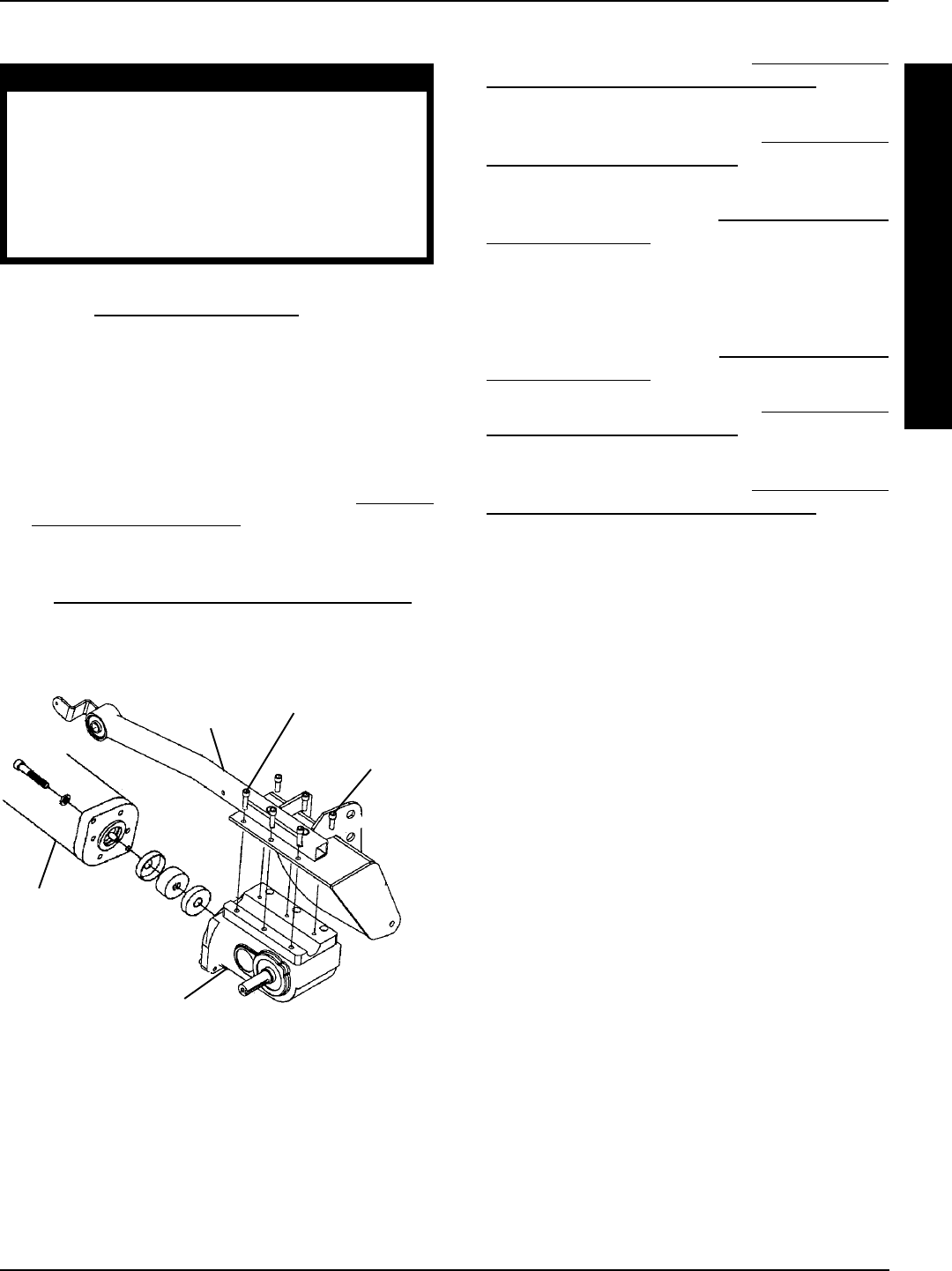
97
PROCEDURE 17
F
W
D
W
H
E
E
L
C
H
A
I
R
S
Installing
CAUTION
The longer socket screws MUST be posi-
tioned in the mounting holes on the OUT-
SIDE of the suspension arm, and the SHORTER
socket screws MUST be positioned in the
mounting holes on the INSIDE of the sus-
pension arm. Otherwise, damage to the
gearbox may result.
1. Install the EXISTING motor onto the NEW gearbox.
Refer to MOTOR REPLACEMENT in PROCEDURE
12 of this manual.
2. Secure the gearbox to the suspension arm using the
six (6) socket screws. Use Loctite 242 and torque
the socket screws to 75-inch pounds.
NOTE: Replace any parts that show signs of wear or dam-
age.
3. Reinstall the side shroud assembly. Refer to REPLAC-
ING THE SIDE SHROUD in this procedure of the
manual.
4. Reinstall the drive wheels onto the wheelchair. Refer
to REMOVING/INSTALLING DRIVE WHEELS in
PROCEDURE 12 of this manual.
SHORT
Socket
Screw
FIGURE 9 - REMOVING/INSTALLING
GEARBOX
SENSOR CABLE ASSEMBLY
REPLACEMENT (FIGURE 10)
1. Remove the rear shroud. Refer to REMOVING/INSTALL-
ING REAR SHROUD in this procedure of the manual.
2. Remove the counterweight. Refer to REMOVING/IN-
STALLING COUNTERWEIGHT in this procedure of
the manual.
3. Remove the battery boxes. Refer to INSTALLING/RE-
MOVING GROUP 24 BATTERY BOXES in PRO-
CEDURE 9 of this manual.
4. Cut tie-wrap A, which secures the EXISTING sensor
cable to the sensor bracket (DETAIL A).
5. Cut tie-wrap B, which secures the EXISTING sensor
cable AND the LEFT motor cable to the battery box
sub-frame (DETAILB).
6. Cut tie-wrap C, which secures the EXISTING Lego
block connector of the sensor cable and the Lego
block connector of the battery wiring harness to the
base frame.
7. Disconnect the EXISTING Lego block connector of
the sensor cable from the Lego block connector of
the battery wiring harness (DETAIL C).
]
8. Remove the two (2) mounting screws, washers and
locknuts that secure the EXISTING sensor to the sen-
sor bracket (DETAIL D).
9. Remove the EXISTING sensor cable assembly.
10. Install the two (2) mounting screws, washers and lock-
nuts to secure the NEW sensor to the sensor bracket
(DETAIL D). Securely tighten.
11. Connect the NEW Lego block connector of the sen-
sor cable assembly to the Lego block connector of
the wiring harness (DETAIL C).
12. Secure the two (2) Lego block connectors to the
base frame with a NEW tie wrap (DETAIL C).
13. Secure the NEW sensor cable AND the LEFT motor
cable to the battery box sub-frame with a NEW tie
wrap (DETAILB).
5. Reinstall the battery boxes. Refer to INSTALLING/RE-
MOVING GROUP 24 BATTERY BOXES in PRO-
CEDURE 9 of this manual.
6. Reinstall the counterweight. Refer to REMOVING/IN-
STALLING COUNTERWEIGHT in this procedure of
the manual.
7. Reinstall the rear shroud. Refer to REMOVING/INSTALL-
ING REAR SHROUD in this procedure of the manual.
Gearbox
Suspension
Arm
Motor
LONG
Socket
Screw
FWD WHEELCHAIRS
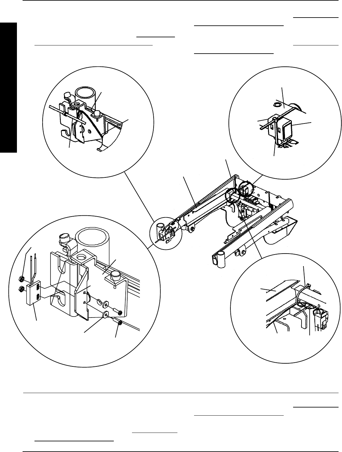
98
FWD WHEELCHAIRSPROCEDURE 17
F
W
D
W
H
E
E
L
C
H
A
I
R
S
Tie Wrap A
Sensor
Cable
Sensor
Bracket
LEFT Motor
Cable Sensor
Cable
Tie Wrap B
Battery
Box Sub-
Frame
Lego
Block
Connector
Of The
Battery
Wiring
Harness
Base Frame
Mounting
Screw
Washer
Locknut
Sensor
Sensor
Bracket
FIGURE 10 - SENSOR CABLE ASSEMBLY REPLACEMENT
Tie Wrap C
Battery Box
Sub-Frame
Base
Frame
DETAIL A
DETAIL B
DETAIL C
DETAIL D
Lego
Block
Connector
Of The
Sensor
Cable
REPLACING SUSPENSION ARM
(FIGURE 11)
1. Remove the rear shroud. Refer to REMOVING/IN-
STALLING REAR SHROUD in this procedure of the
manual.
NOTE: Seat frame and drive wheels removed for clarification purposes ONLY.
REAR OF
CHAIR
FRONT OF
CHAIR
2. Remove the counterweight. Refer to REMOVING/IN-
STALLING COUNTERWEIGHT in this procedure of
the manual.
16. Reinstall the counterweight. Refer to REMOVING/IN-
STALLING COUNTERWEIGHT in this procedure of
the manual.
17. Reinstall the rear shroud. Refer to REMOVING/IN-
STALLING REAR SHROUD in this procedure of the
manual.
14. Secure the NEW sensor cable to the sensor bracket
with a NEW tie wrap (DETAIL A).
15. Reinstall the battery boxes. Refer to INSTALLING/
REMOVING GROUP 24 BATTERY BOXES in PRO-
CEDURE 9 of this manual.
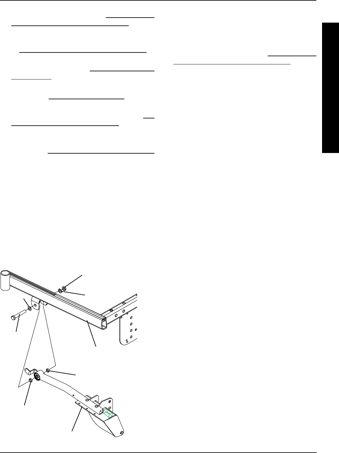
99
F
W
D
W
H
E
E
L
C
H
A
I
R
S
REMOVING/INSTALLING WIRING
HARNESS (FIGURE 12)
Removing
1. Remove the battery boxes. Refer to INSTALLING/RE-
MOVING GROUP 24 BATTERY BOXES in PRO-
CEDURE 9 of this manual.
2. Remove the two (2) mounting screws that secure
the battery charger port to the mounting bracket and
remove the battery charger port (DETAIL A).
3. Remove the two (2) mounting screws and locknuts
that secure the wiring harness w/bracket to the battery
box sub-frame (DETAIL B).
4. Cut tie-wrap A, which secures the Lego block
connectors to the base frame (DETAIL C).
5. Disconnect the Lego block connector of the bat-
tery wiring harness from the Lego block connec-
tor of the sensor cable assembly (DETAIL C).
6. Cut tie-wrap B, which secures the battery charger
cable and the RIGHT motor cable to the battery
box sub-frame (DETAIL D).
7. Disconnect the battery harness/charger cable
(BLUE) from the controller connector (BLUE)
(DETAILE).
8. Remove the wiring harness.
Installing
1. Connect the battery harness/charger cable (BLUE)
to the controller connector (BLUE) (DETAILE).
2. Connect the Lego block connector of the battery wir-
ing harness to the Lego block connector of the sen-
sor cable assembly (DETAIL C).
3. Secure the Lego block connectors to the base frame
with a NEW tie wrap (DETAIL C).
4. Install the two (2) mounting screws and locknuts that
secure the wiring harness w/bracket to the battery
box sub-frame. Use Loctite 242 and torque mounting
screws to 160-inch pounds (DETAIL B).
5. Secure the battery charger cable and the RIGHT mo-
tor cable to the battery box sub-frame with a NEW tie
wrap (DETAIL D).
Base
Frame
FIGURE 11 - REPLACING THE SUSPENSION ARM
Locknut
Suspension Arm
Spacer
Mounting
Screw
Spacer
WasherWasher
FWD WHEELCHAIRS PROCEDURE 17
3. Remove the battery boxes. Refer to INSTALLING/RE-
MOVING GROUP 24 BATTERY BOXES in PRO-
CEDURE 9 of this manual.
4. Remove the drive wheel from the wheelchair. Refer
to REMOVING/INSTALLING DRIVE WHEELS in
PROCEDURE 12 of this manual.
5. Remove the shock. Refer to REMOVING/INSTALL-
ING SHOCKS in this procedure of this manual.
6. Remove the tie rods from the EXISTING suspension
arm. Refer to TIE ROD REPLACEMENT in this pro-
cedure of the manual.
7. Remove the side shroud assembly. Refer to RE-
PLACING SIDE SHROUD ASSEMBLY in this proce-
dure of the manual.
8. Remove the gearbox from the EXISTING suspension
arm. Refer to REMOVING/INSTALLING GEARBOX
in this procedure of the manual.
9. Remove the locknut, two (2) spacers, two (2) wash-
ers and the mounting screw that secures the EXIST-
ING suspension arm to the base frame.
10. Remove EXISTING suspension arm from the base
frame.
11. Secure the NEW suspension arm to the base frame
using the mounting screw, two (2) washers, two (2)
spacers and the locknut. Torque the locknuts to 85
-inch pounds.
12. Reassemble the wheelchair by reversing STEPS 1-8.
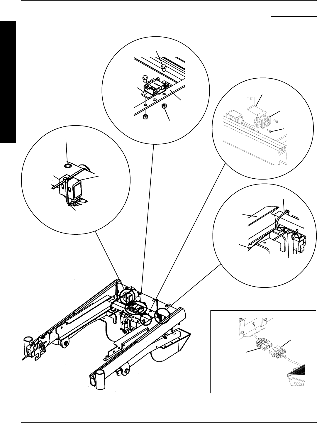
100
Lego Block
Connector
Of The
Battery
Wiring
Harness
Base Frame
Tie Wrap A
RIGHT
Motor
Cable Battery Charger
Cable
Tie Wrap B
Battery
Box Sub-
Frame
FIGURE 12 - REMOVING/INSTALLING WIRING HARNESS
DETAIL B
DETAIL C
DETAIL D
Mounting Screws
Locknuts
Wiring
Harness W/
Bracket Battery
Box Sub-
Frame
DETAIL E
Battery
Harness/
Charger
Cable (Blue)
Controller
Connector
(Blue)
FWD WHEELCHAIRSPROCEDURE 17
F
W
D
W
H
E
E
L
C
H
A
I
R
S
Lego
Block
Connector
Of The
Sensor
Cable
Mounting
Screw
Mounting
Bracket
Battery
Charger
Port
DETAIL A
6. Reinstall the mounting screw that secures the battery
charger port to the mounting bracket (DETAILA). Se-
curely Tighten.
7. Reinstall the battery boxes. Refer to INSTALLING/RE-
MOVING GROUP 24 BATTERY BOXES in PRO-
CEDURE 9 of this manual.
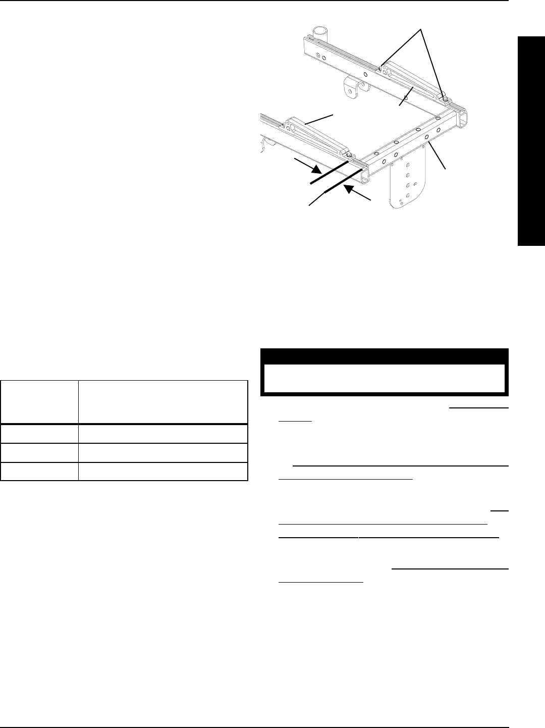
101
PROCEDURE 17FWD WHEELCHAIRS
ADJUSTING WEIGHT
DISTRIBUTION (FIGURE 13)
NOTE: Depending on the seat depth ordered, the position
of the seat support brackets is factory set between 2.25 and
6 inches (measured from the front of the base frame to the
front of the seat support brackets). This will put approximately
65% of the total weight of the chair and user over the drive
wheels (large wheels), allowing for the best performance of
the chair.
In order to achieve maximum comfort and maneuverability
for the end user, it may be necessary to adjust the seat
support brackets slightly forward or backward. It is recom-
mended that the seat support brackets be set as close to
2.25 - 6 inch mark (depending on seat depth) as possible,
while allowing maximum comfort and maneuverability to
the end user.
Adjusting Weight Distribution For New Seat
Depth
NOTE: When changing the seat depth of the chair, it is
necessary to adjust the seat support brackets in order to
achieve optimum weight distribution (65%). Perform the
following procedure to adjust the seat brackets:
1. Refer to the following chart to determine the correct
position of the two (2) seat support brackets to achieve
optimum weight distribution (65%).
2. Loosen the four (4) mounting screws that secure the
two (2) seat support brackets to the base frame.
3. Adjust the two (2) seat support brackets forward or
backward until the position determined in STEP 1 is
achieved.
NOTE: When the front of the seat aligns with the controller,
approximately 65% of the total weight of the chair and user is
over the drive wheels (large wheels).
4. Adjust the two (2) seat brackets slightly forward or
backward, until maximum comfort and maneuver-
ability for the end user is acheived.
5. Retighten the four (4) mounting screws securing the
two (2) seat support brackets to the base frame.
Seat Support
Brackets
Mounting Screws
Seat
Depth
(Inches)
Position Of The Seat Support
Brackets (Inches) To Achieve
Optimum Weight Distribution (65%)
14 to 16 inches 2.25-inches
17 to 18 inches 4.25-inches
19 to 20 inches 6-inches
INSTALLING 90o FOOTBOARD
(FIGURE 14)
WARNING
DO NOT remove detent pin from footrest
assembly. Otherwise, injury may result.
1. Remove the existing footrests. Refer to FRONT RIG-
GINGS in PROCEDURE 3 of the Owners manual,
part number 1081227.
2. Remove the telescoping front rigging supports. Refer
to ADJUSTING/REPLACING TELESCOPING
FRONT RIGGING SUPPORT in PROCEDURE 3 of
the Owners Manual, part number 1081227.
3. Remove existing front and rear shrouds. Refer to RE-
MOVING/INSTALLING THE REAR SHROUD and
REMOVING/INSTALLING THE FRONT SHROUD in
this procedure of the Manual.
4. Remove the seat. Refer to REMOVING/INSTALLING
THE SEAT FRAME in PROCEDURE 6 of this Manual.
5. Position the 90o footboard on the base frame as shown
in FIGURE 14.
6. Loosely install one (1) mounting screw into the back
of the footboard and into the base frame.
7. Loosely install two (2) mounting screws and washers
through the top of the footboard and into the base frame.
8. Torque all three (3) mounting screw between 15 and
19-foot pounds.
Front Of
Base
Frame
FIGURE 13 - ADJUSTING WEIGHT
DISTRIBUTION
2.25 Inches (For a
seat depth of 14 to
16 inches)
NOTE: Seat/seat frame not shown for clarity.
F
W
D
W
H
E
E
L
C
H
A
I
R
S
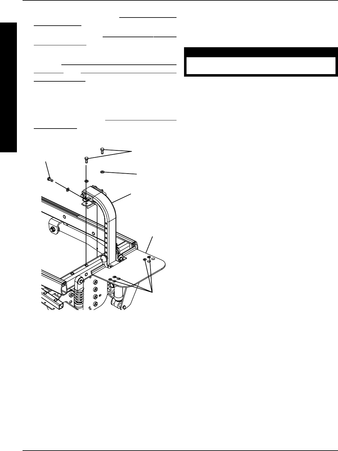
102
PROCEDURE 17
F
W
D
W
H
E
E
L
C
H
A
I
R
S
FIGURE 14 - INSTALLING 90o FOOTBOARD
Flat Screws
Washers
Locknuts
90o Footrest
Support
Mounting
Screws
(STEP 7)
Washer
90o
Footboard
Mounting
Screw (STEP 6)
FOOTBOARD ADJUSTMENTS-
DEPTH/HEIGHT/ANGLE
(FIGURE 15)
WARNING
DO NOT remove detent pin from footrest
assembly. Otherwise, injury may result.
Depth
1. Remove the four (4) flat screws, washers and locknuts
that secure 90o footboard to the two (2) half clamps.
NOTE: Observe the angle of the footboard for reinstallation.
2. Move
footboard to one (1) of two (2) mounting positions.
3. Secure the footboard to the half clamps with the four
(4) flat screws, washers and locknuts. Securely tighten.
Angle
1. Loosen, but do not remove the four (4) flat screws,
washers and locknuts that secure the footplate to the
half clamps.
2. Position the 90o footboard to the desired angle.
3. Retighten four (4) flat screws, washers and locknuts.
Height
1. Remove the two (2) hub caps.
2. Remove the mounting screw, washers, caplug
washers, and locknut that secure the footboard to
the footrest support.
3. Adjust footboard to desired height.
4. Secure the footboard with the mounting screw,
washers, caplug washers, and locknut. Tighten
mounting screw and locknut to 12 foot pounds. See
FIGURE 15 for hardware orientation.
9. Adjust angle of footrest. Refer to FOOTREST ANGLE
ADJUSTMENTS in this procedure of the Manual.
10. Install the seat. Refer to REMOVING/INSTALLING
THE SEAT FRAME in PROCEDURE 6 of this manual.
11. Install NEW front shroud and existing rear shroud.
Refer to REMOVING/INSTALLING THE REAR
SHROUD and REMOVING/INSTALLING THE
FRONT SHROUD in this procedure of the Manual.
12. Install the two (2) end caps provided into the ends of
the seat frame where the telescoping front rigging sup-
ports were mounted.
13. Adjust footboard. Refer to DEPTH/HEIGHT/ANGLE
ADJUSTMENT in this procedure of the manual.
FWD WHEELCHAIRS
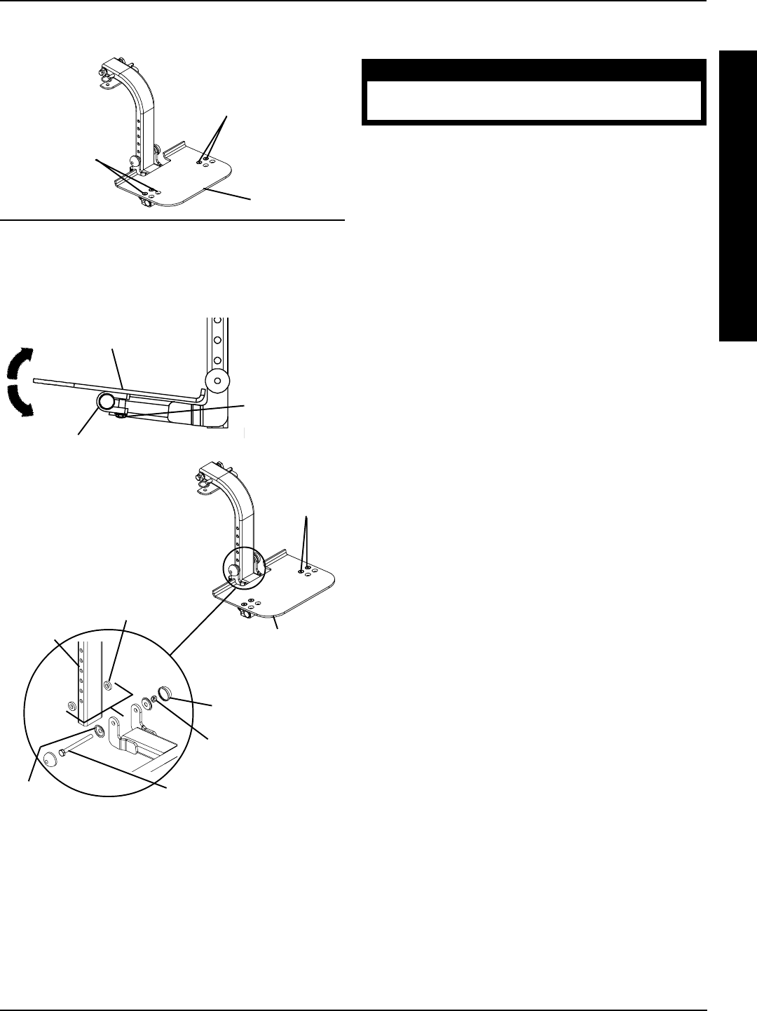
103
F
W
D
W
H
E
E
L
C
H
A
I
R
S
FWD WHEELCHAIRS PROCEDURE 17
FOOTREST ANGLE ADJUSTMENTS
WARNING
DO NOT remove detent pin from footrest
assembly. Otherwise, injury may result.
Footrest Angle Adjustment Relative to the
Vertical Position of the Front Shroud
(FIGURE 16)
NOTE: The angle of the footrest relative to the vertical
position of the front shroud can be increased or decreased
by adjusting both cams located at the top of the footrest
support.
1. Loosen the mounting screw and locknut that secure
the cams to the upper mounting bracket. Refer to
DETAIL A.
NOTE: Both cams MUST be rotated to the same posi-
tion to keep the footrest square to the base.
2. Rotate both cams either direction until footrest is at
desired angle. Refer to DETAIL B and C
3. Tighten mounting screw and locknut to 12 foot pounds.
Footrest Angle Adjustment Relative to the
Horizontal Position of the Front Shroud
(FIGURE 16)
NOTE: The footrest is factory set to be square to the base
when installed. The footrest can be positioned to be out of
square by adjusting only one (1) of the cams located at the
top of the footrest support.
1. Loosen the mounting screw and locknut that secure the
cams to the upper mounting bracket. Refer to DETAIL
A.
2. Perform one (1) of the following:
NOTE: Right and Left are determined by sitting in the
wheelchair.
A. Turning the right cam will rotate the footrest counter-
clockwise. Refer to DETAIL D.
B. Turning the left cam will rotate the footrest clock-
wise. Refer to DETAIL D.
3. When footrest is at desired position, tighten mounting
screw and locknut to 12 foot pounds.
FIGURE 15 - DEPTH/HEIGHT/ANGLE
ADJUSTMENT
Half Clamp
Side View Of 90o Footboard
Flat Screws
(Loosen
Here)
Flat Screws
Washers
Locknuts
Footboard
Caplug Mounting Screw
Washer
Hub Cap
Locknut
Footrest
Support
DEPTH
ANGLE/HEIGHT
Two (2)
Mounting
Positions
Flat Screws
Washers
Locknuts
Footboard
Washer/
Locknut
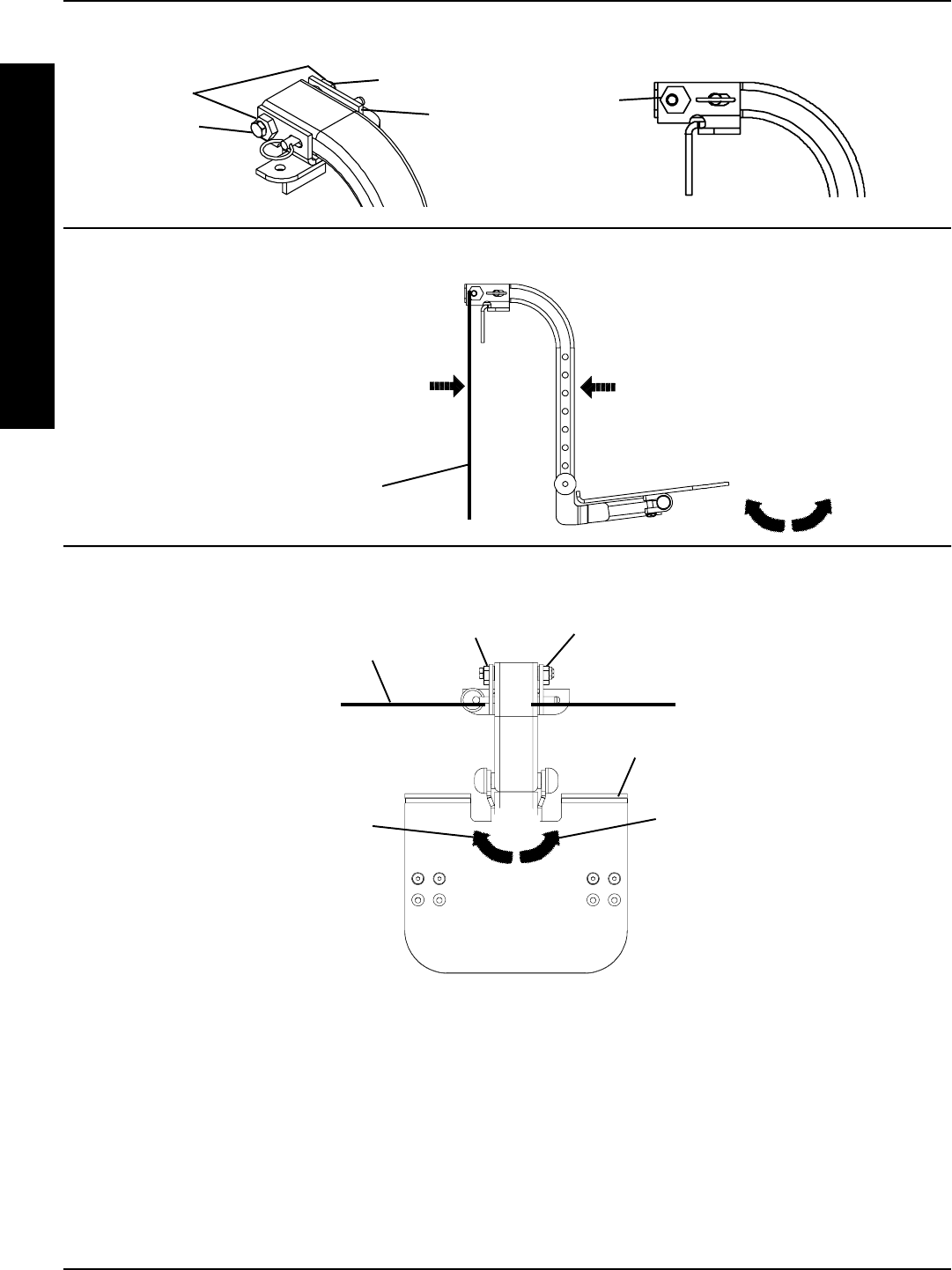
104
FIGURE 16 - FOOTREST ANGLE ADJUSTMENTS
Mounting
Screw
Locknut
Cams Cam
Upper
Mounting
Bracket
DETAIL “A”DETAIL “B”
DETAIL “C” - SIDE VIEW OF FOOTREST
DETAIL “D” - TOP VIEW OF FOOTREST
Vertical Position
of Front Shroud
NOTE: Angle is
increased or
decreased depending
on direction of footrest
rotation
Right
Cam
Left
Cam
Footrest
COUNTER-
CLOCKWISE
Direction of
Footrest Rotation
Horizontal Position
of Front Shroud
CLOCKWISE
Direction of
Footrest
Rotation
PROCEDURE 17
F
W
D
W
H
E
E
L
C
H
A
I
R
S
FWD WHEELCHAIRS

105
NOTES
NOTES
N
O
T
E
S

106
NOTES
NOTES
N
O
T
E
S

107
LIMTIED WARRANTY
L
I
M
I
T
E
D
W
A
R
R
A
N
T
Y
LIMITED WARRANTY
PLEASE NOTE: THE WARRANTY BELOW HAS BEEN DRAFTED TO COMPLY WITH FEDERAL LAW
APPLICABLE TO PRODUCTS MANUFACTURED AFTER JULY 4, 1975.
This warranty is extended only to the original purchaser/user of our products.
This warranty gives you specific legal rights and you may also have other legal rights
which vary from state to state.
Invacare warrants seat frame to be free from defects in materials and workmanship
for a period of three (3) years from date of purchase; that electrical components are
warranted for a period of one (1) year; gearbox/motors for a period of 18 months; and
gearless/brushless motors for five (5) years from the date of purchase; and the base
frame for the life of the product; all remaining components (including gas cylinders and
motor lock pads) for one (1) year from the date of purchase except upholstered mate-
rials, padded materials and tires/wheels. If within such warranty period any such prod-
uct shall be proven to be defective, such product shall be repaired or replaced, at
Invacare's option. This warranty does not include any labor or shipping charges in-
curred in replacement part installation or repair of any such product. Invacare's sole
obligation and your exclusive remedy under this warranty shall be limited to such repair
and/or replacement.
This warranty pertains to Arrow Series, Ranger X Series and Torque Series Only!
For warranty service, please contact the dealer from whom you purchased your In-
vacare product. In the event you do not receive satisfactory warranty service, please
write directly to Invacare at the address at the bottom of the back cover. Provide
dealer’s name, address, date of purchase, indicate nature of the defect and, if the
product is serialized, indicate the serial number. Do not return products to our factory
without our prior consent.
LIMITATIONS AND EXCLUSIONS: THE FOREGOING WARRANTY SHALL NOT APPLY TO SERIAL
NUMBERED PRODUCTS IF THE SERIAL NUMBER HAS BEEN REMOVED OR DEFACED, PROD-
UCTS SUBJECTED TO NEGLIGENCE, ACCIDENT, IMPROPER OPERATION, MAINTENANCE OR
STORAGE, COMMERCIAL OR INSTITUTIONAL USE, PRODUCTS MODIFIED WITHOUT
INVACARE'S EXPRESS WRITTEN CONSENT INCLUDING, BUT NOT LIMITED TO, MODIFICA-
TION THROUGH THE USE OF UNAUTHORIZED PARTS OR ATTACHMENTS; PRODUCTS DAM-
AGED BY REASON OF REPAIRS MADE TO ANY COMPONENT WITHOUT THE SPECIFIC CON-
SENT OF INVACARE, OR TO A PRODUCT DAMAGED BY CIRCUMSTANCES BEYOND
INVACARE'S CONTROL, AND SUCH EVALUATION WILL BE SOLELY DETERMINED BY INVAC-
ARE. THE WARRANTY SHALL NOT APPLY TO PROBLEMS ARISING FROM NORMAL WEAR OR
FAILURE TO ADHERE TO THESE INSTRUCTIONS.
THE FOREGOING WARRANTY IS EXCLUSIVE AND IN LIEU OF ALL OTHER EXPRESS WARRAN-
TIES. IMPLIED WARRANTIES, IF ANY, INCLUDING THE IMPLIED WARRANTIES OF MERCHANT-
ABILITY AND FITNESS FOR A PARTICULAR PURPOSE, SHALL NOT EXTEND BEYOND THE DURA-
TION OF THE EXPRESS WARRANTY PROVIDED HEREIN AND THE REMEDY FOR VIOLATIONS OF
ANY IMPLIED WARRANTY SHALL BE LIMITED TO REPAIR OR REPLACEMENT OF THE DEFEC-
TIVE PRODUCT PURSUANT TO THE TERMS CONTAINED HEREIN. INVACARE SHALL NOT BE
LIABLE FOR ANY CONSEQUENTIAL OR INCIDENTAL DAMAGES WHATSOEVER.
THIS WARRANTY SHALL BE EXTENDED TO COMPLY WITH STATE/PROVINCIAL LAWS AND RE-
QUIREMENTS.

Invacare Corporation www.invacare.com
U S A Canada Invacare, Storm Series, and Arrow are registered trademarks of
One Invacare Way 5970 Chedworth Way Invacare Corporation.
Elyria, Ohio USA Mississauga, Ontario Yes, You can., Ranger X, and Torque are trademarks of
44036-2125 L5R 3T9, Canada Invacare Corporation.
800-333-6900 905-890-8838 Loctite is a registered trademark of Loctite Corporation.
© 2001 Invacare Corporation
Form No. 98-266 Part No. 1081229 Rev C (1)-4/01
