Invacare Tdx Sp Users Manual 1143190C
SP to the manual 00b12b43-af36-46f3-a1af-442d5e39ce43
2015-02-02
: Invacare Invacare-Tdx-Sp-Users-Manual-433555 invacare-tdx-sp-users-manual-433555 invacare pdf
Open the PDF directly: View PDF ![]() .
.
Page Count: 72

Owner’s Operator and Maintenance Manual
DEALER: This manual MUST be given to
the user of the wheelchair.
USER: BEFORE using this wheelchair, read
this manual and save for future reference.
For more information regarding
Invacare products, parts, and services,
please visit www.invacare.com
TDX™ SP
Power Wheelchair Base

REFERENCE DOCUMENTS
TDX™ SP 2Part No 1143190
WARNING
A QUALIFIED TECHNICIAN MUST PERFORM THE INITIAL SET UP
OF THIS WHEELCHAIR. ALSO, A QUALIFIED TECHNICIAN MUST
PERFORM ALL PROCEDURES IN THE SERVICE MANUAL.
WHEELCHAIR USERS: DO NOT SERVICE OR OPERATE THIS
EQUIPMENT WITHOUT FIRST READING AND UNDERSTANDING
(1) THE OWNER’S OPERATOR AND MAINTENANCE MANUAL
AND (2) THE SEATING SYSTEM’S MANUAL (IF APPLICABLE). IF
YOU ARE UNABLE TO UNDERSTAND THE WARNINGS,
CAUTIONS, AND INSTRUCTIONS, CONTACT INVACARE
TECHNICAL SUPPORT BEFORE ATTEMPTING TO SERVICE OR
OPERATE THIS EQUIPMENT - OTHERWISE INJURY OR DAMAGE
MAY RESULT.
DEALERS AND QUALIFIED TECHNICIANS: DO NOT SERVICE OR
OPERATE THIS EQUIPMENT WITHOUT FIRST READING AND
UNDERSTANDING (1) THE OWNER’S OPERATOR AND
MAINTENANCE MANUAL, (2) THE SERVICE MANUAL (IF
APPLICABLE) AND (3) THE SEATING SYSTEM’S MANUAL (IF
APPLICABLE). IF YOU ARE UNABLE TO UNDERSTAND THE
WARNINGS, CAUTIONS AND INSTRUCTIONS, CONTACT
INVACARE TECHNICAL SUPPORT BEFORE ATTEMPTING TO
SERVICE OR OPERATE THIS EQUIPMENT - OTHERWISE, INJURY
OR DAMAGE MAY RESULT.
REFERENCE DOCUMENTS
Refertothetablebelowforpartnumbersofadditionaldocumentswhicharereferenced
inthismanual.
MANUAL PART NUMBER
MK6i™ Electronics Programming Guide 1141471
MK6i™ Electronics Service Manual 1143203
Adjustable ASBA Owner’s Manual 1143196
Van Seat Owner’s Manual 1143195
Formula™ CG Seating System 1143155
TDX SP Service Manual 1143209
Adjustable ASBA Service Manual 1143238
NOTE:Updatedversionsofthismanualareavailableonwww.invacare.com.

TABLE OF CONTENTS
Part No 1143190 3TDX™ SP
TABLE OF CONTENTS
REFERENCE DOCUMENTS ................................................................. 2
REGISTER YOUR PRODUCT................................................................ 6
SPECIAL NOTES ................................................................................ 9
LABEL LOCATIONS ......................................................................... 11
All Wheelchairs.........................................................................................................................................11
Wheelchairs with TRRO ........................................................................................................................13
Wheelchairs without TRRO..................................................................................................................13
TYPICAL PRODUCT PARAMETERS .................................................. 14
SECTION 1—GENERAL GUIDELINES ................................................. 15
Repair or Service Information ...............................................................................................................15
Operation Information............................................................................................................................16
Wheelchairs with TRRO or TRBKTS Only...................................................................................17
Tire Pressure.............................................................................................................................................17
Electrical .....................................................................................................................................................18
Grounding Instructions.......................................................................................................................18
Batteries......................................................................................................................................................18
Charging Batteries ...............................................................................................................................18
Rain Test.....................................................................................................................................................19
Weight Training ........................................................................................................................................19
Weight Limitation.....................................................................................................................................19
SECTION 2—EMI INFORMATION ..................................................... 20
SECTION 3—SAFETY/HANDLING OF WHEELCHAIRS ......................... 22
Stability and Balance.................................................................................................................................22
Coping with Everyday Obstacles ..........................................................................................................23
A Note to Wheelchair Assistants ........................................................................................................24
Reaching, Leaning and Bending - Forward..........................................................................................24
Reaching, Bending - Backward...............................................................................................................25
Pinch Points................................................................................................................................................25
Stairways.....................................................................................................................................................26
Transferring To and From Other Seats ..............................................................................................27

TABLE OF CONTENTS
TDX™ SP 4Part No 1143190
TABLE OF CONTENTS
SECTION 4—SAFETY INSPECTION/TROUBLESHOOTING .................... 28
Safety Inspection Checklists...................................................................................................................28
Inspect/Adjust Initially .........................................................................................................................28
Inspect/Adjust Weekly........................................................................................................................29
Inspect/Adjust Monthly.......................................................................................................................29
Inspect/Adjust Periodically.................................................................................................................30
Inspect/Adjust Every 18 Months.......................................................................................................30
Inspect/Adjust Every 2 Years ............................................................................................................30
Troubleshooting - Mechanical ..............................................................................................................30
Troubleshooting - Electrical...................................................................................................................31
SPJ™+, SPJ+ w/PSS or SPJ+ w/ACC Joysticks ..............................................................................31
MPJ™+, PSR+, PSF+ Joysticks or Displays.....................................................................................32
Checking Battery Charge Level.............................................................................................................34
SECTION 5—WHEELCHAIR OPERATION ........................................... 35
Operating the Wheelchair......................................................................................................................35
Turning the Power On/Off................................................................................................................35
Using the Joystick to Drive the Wheelchair..................................................................................35
SPJ+, MK6i™ SPJ+ w/PSS and MK6i SPJ+ w/ACC Joystick Switches and Indicators ...............37
On/Off Button ......................................................................................................................................37
Speedometer.........................................................................................................................................37
Speed Control Buttons.......................................................................................................................38
Joystick....................................................................................................................................................38
Charger/Programming Input..............................................................................................................38
Service Indicator...................................................................................................................................38
Information Gauge Display ................................................................................................................39
MPJ+ Joystick Switches and Indicators ................................................................................................39
Drive Select Toggle Switch................................................................................................................39
Speed Control ......................................................................................................................................40
Joystick....................................................................................................................................................40
Charger/Programming Input..............................................................................................................40
LCD Display Screens...........................................................................................................................40
Programmable Mono Port 1/2 or External Mode Switch...........................................................43
Remote On/Off Switch.......................................................................................................................44
Mode Switch..........................................................................................................................................44
Memory Card Slot...............................................................................................................................44
Repositioning Joystick..............................................................................................................................45
Van Seats................................................................................................................................................45
Adjustable ASBA Seats........................................................................................................................46
Disconnecting/Connecting the Joysticks.............................................................................................46
SPJ+ Joysticks ........................................................................................................................................46
MPJ+ Joysticks.......................................................................................................................................47

TABLE OF CONTENTS
Part No 1143190 5TDX™ SP
TABLE OF CONTENTS
SECTION 6—MOTOR LOCKS ............................................................ 48
Disengaging/Engaging Motor Lock Levers...........................................................................................48
SECTION 7—WHEEL LOCKS ............................................................. 49
Disengaging/Engaging the Wheel locks................................................................................................49
Engaging..................................................................................................................................................49
Disengaging............................................................................................................................................49
SECTION 8—FOOTBOARD ASSEMBLY .............................................. 50
Removing/Installing the Footboard.......................................................................................................50
Removing ...............................................................................................................................................50
Installing..................................................................................................................................................50
Adjusting the Footboard Angle .............................................................................................................51
SECTION 9—FORKS ........................................................................ 52
Adjusting Forks .........................................................................................................................................52
SECTION 10—BATTERIES ................................................................ 53
Using the Proper Batteries.....................................................................................................................54
Replacing Batteries...................................................................................................................................55
Cleaning Battery Terminals....................................................................................................................57
Removing/Installing the Batteries From/Into the Wheelchair........................................................57
Removing the Front Shroud/Battery Retention Bracket and Rear Shroud............................57
Removing the Batteries from Wheelchair .....................................................................................59
Installing Batteries into Wheelchair.................................................................................................59
Installing the Front Shroud/Battery Retention Bracket and Rear Shroud ..............................60
When to Charge Batteries.....................................................................................................................61
SPJ+, SPJ+ w/PSS and SPJ+ w/ACC Joysticks.................................................................................61
MPJ+ Joystick.........................................................................................................................................61
Charging Batteries....................................................................................................................................62
Description and Use of Battery Chargers......................................................................................62

TDX™ SP 6Part No 1143190
SECTION 11—TRANSPORT READY PACKAGE (TRRO) ...................... 64
About Transport Ready Packages.........................................................................................................65
Compliance Information .........................................................................................................................65
Specifications.........................................................................................................................................66
Securing the Wheelchair to the Vehicle .............................................................................................66
Positioning the Wheelchair in the Vehicle.....................................................................................66
Securement Points...............................................................................................................................67
Securing the Wheelchair ....................................................................................................................67
Securing the Occupant............................................................................................................................68
Wheelchair-Anchored Belts..............................................................................................................68
Vehicle-Anchored Belts......................................................................................................................70
Seating System ......................................................................................................................................70
Positioning Belts ...................................................................................................................................71
LIMITED WARRANTY ..................................................................... 72
REGISTER YOUR PRODUCT
The benefits of registering:
1. Safeguard your investment.
2. Ensure long term maintenance and servicing of your purchase.
3. Receive updates with product information, maintenance tips, and industry news.
4. Invacare can contact you or your provider, if servicing is needed on your product.
5. It will enable Invacare to improve product designs based on your input and needs.
Register ONLINE at www.invacare.com
- or -
Complete and mail the form on the next page
Any registration information you submit will be used by Invacare Corporation only, and
protected as required by applicable laws and regulations.

Part No 1143190 7TDX™ SP
Name _______________________________________________________________
Address _____________________________________________________________
City ___________________ State/Province __________
Zip/Postal Code ________
Email ___________________________________ Phone No. _________________
Invacare Model No. ______________________ Serial No. __________________
Purchased From _________________________Date of Purchase:___________
1. Method of purchase: (check all that apply)
❏ Medicare ❏ Insurance ❏ Medicaid ❏ Other __________________________
2. This product was purchased for use by: (check one)
❏ Self ❏ Parent ❏ Spouse ❏ Other
3. Product was purchased for use at:
❏ Home ❏ Facility ❏ Other
4. I purchased an Invacare product because:
❏ Price ❏ Features (list features) _________________________________________
5. Who referred you to Invacare products? (check all that apply)
❏ Doctor ❏ Therapist ❏ Friend ❏ Relative ❏ Dealer/Provider ❏ Other_________
❏ Advertisement (circle one): TV, Radio, Magazine, Newspaper ❏ No Referral_____
6. What additional features, if any, would you like to see on this product?
__________________________________________________________________________
7. Would you like information sent to you about Invacare products that may be available for a
particular medical condition? ❏ Yes ❏ No
If yes, please list any condition(s) here and we will send you information by email and/or mail about
any available Invacare products that may help treat, care for or manage such condition(s):
__________________________________________________________________________
8. Would you like to receive updated information via email or regular mail about the Invacare
home medical products sold by Invacare's dealers? ❏ Yes ❏ No
9. What would you like to see on the Invacare website?
__________________________________________________________________________
10. Would you like to be part of future online surveys for Invacare products? ❏ Yes ❏ No
11. User's Year of birth: ______________________________________________________
If at any time you wish not to receive future mailings from us, please contact us at Invacare Corporation,
CRM Department, 39400 Taylor Parkway, Elyria, OH 44035, or fax to 877-619-7996 and we will remove
you from our mailing list.
To find more information about our products, visit www.invacare.com.
PRODUCT REGISTRATION FORM
Register ONLINE at www.invacare.com - or -
Complete and mail this form
Cut Along Line
Fold
here
Fold
here

SPECIAL NOTES
Part No 1143190 9TDX™ SP
SPECIAL NOTES
Signalwordsareusedinthismanualandapplytohazardsorunsafepracticeswhich
couldresultinpersonalinjuryorpropertydamage.Refertothetablebelowfor
definitionsofthesignalwords.
NOTICE
THE INFORMATION CONTAINED IN THIS DOCUMENT IS SUBJECT TO
CHANGE WITHOUT NOTICE.
WHEELCHAIR USER
As a manufacturer of wheelchairs, Invacare endeavors to supply a wide variety of
wheelchairs to meet many needs of the end user. However, final selection of the
type of wheelchair to be used by an individual rests solely with the user and his/her
healthcare professional capable of making such a selection. Invacare highly
recommends working with a certified rehab technology supplier and/or a member
of NRRTS or RESNA.
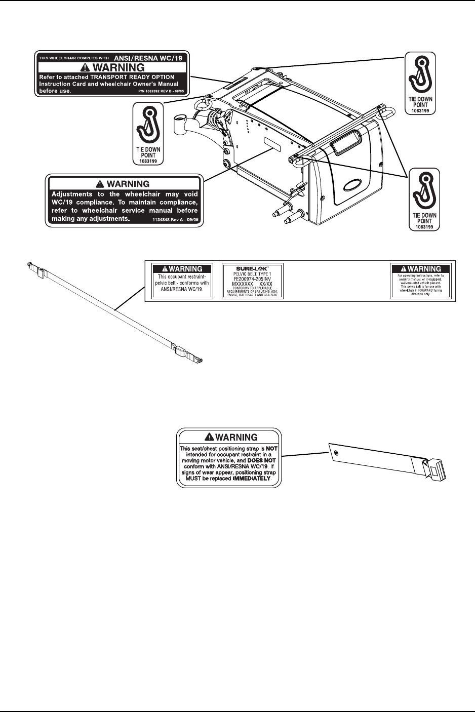
WHEELCHAIR TIE-DOWN RESTRAINTS AND SEAT RESTRAINTS (TRRO OR
TRBKTS)
TRRO includes four factory-installed transport brackets and a wheelchair anchored
pelvic belt. TRRO has been crash-tested in accordance with ANSI/RESNA WC Vol 1
Section 19 Frontal Impact Test requirements for wheelchairs with a 168 lb crash
dummy, which corresponds to a person with a weight of 114 to 209 lbs.
TRBKTS includes four factory-installed wheelchair transport brackets. TRBKTS has
not been crash-tested in accordance with WC 19. Use these transport brackets only
to secure an unoccupied wheelchair during transport.
As of this date, the Department of Transportation has not approved any tie-down
systems for transportation of a user while in a wheelchair, in a moving vehicle of any
type. It is Invacare’s position that users of wheelchairs should be transferred into
appropriate seating in vehicles for transportation and use be made of the restraints
made available by the auto industry. Invacare cannot and does not recommend any
wheelchair transportation systems.
Refer to Transport Ready Package (TRRO) on page 64 for more information about
transporting the wheelchair.
SIGNAL WORD MEANING
DANGER
Danger indicates an imminently hazardous situation which, if not avoided,
will result in death or serious injury.
WARNING
Warning indicates a potentially hazardous situation which, if not avoided,
could result in death or serious injury.
CAUTION
Caution indicates a potentially hazardous situation which, if not avoided,
may result in property damage.

SPECIAL NOTES
TDX™ SP 10 Part No 1143190
TRRO AND TRBKTS WARNINGS
Only use the transport brackets included with TRRO and TRBKTS for the purposes
described in this manual.
Battery support brackets MUST be installed at all times. Otherwise, the wheelchair
will not be WC/19 compliant. Refer to Removing/Installing the Batteries From/Into
the Wheelchair on page 57.
WARNING
Invacare products are specifically designed and manufactured for use in conjunction
with Invacare accessories. Accessories designed by other manufacturers have not
been tested by Invacare and are not recommended for use with Invacare products.
The seat positioning strap is a positioning belt ONLY. It is not designed for use as a
safety device withstanding high stress loads such as auto or aircraft safety belts. If
signs of wear appear, belt MUST be replaced IMMEDIATELY.
The drive behavior initially experienced by the user may be different from other
wheelchairs previously used. This power wheelchair has Invacare’s SureStep®
technology, a feature that provides the wheelchair with optimum traction and
stability when driving forward over transitions and thresholds of up to 3-inches. The
following warnings apply specifically to the SureStep feature:
• DO NOT use on inclines greater than 9°.
• DO NOT use on inclines with wet, slippery, icy or oily surfaces. This may include
certain painted or otherwise treated wood surfaces.
• DO NOT traverse down ramps at high speed. Doing so will reduce traction and
increase stopping distance.
• The end user’s weight can materially affect traction on sloped surfaces. Great
care should be taken when traversing such slopes.
To determine and establish your particular safety limits, practice use of this product
on various sloping surfaces in the presence of a qualified healthcare provider before
attempting active use of this wheelchair. Other general warnings listed within this
document also apply.
Wheelchairs should be examined during maintenance for signs of corrosion (water
exposure, incontinence, etc.). Electrical components damaged by corrosion should
be replaced IMMEDIATELY.
Wheelchairs that are used by incontinent users and/or are frequently exposed to
water may require replacement of electrical components more frequently.
LABEL LOCATIONS
Part No 1143190 11 TDX™ SP
LABEL LOCATIONS
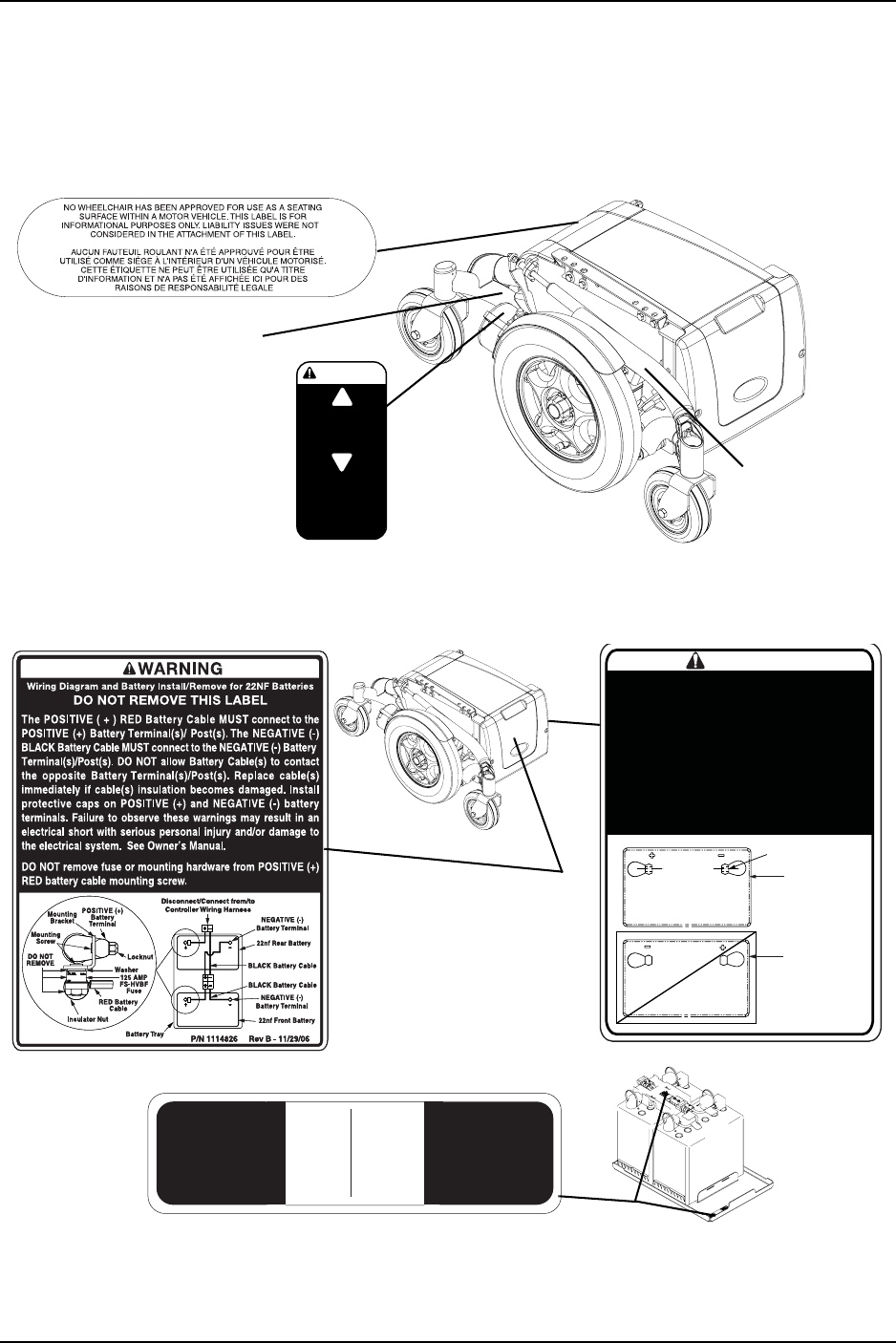
All Wheelchairs
Wheelchairs with 22NF Batteries
Serial Number Label is
located on the right
side rear swingarm.
Weight Capacity
Label located
here
P/N 1118367
Rev A - 3/03
DRIVE
PUSH
CAUTION
Ensure both clutches
are fully engaged
before driving chair
Located on each
4-pole motor
P/N 1118356
P/N 1118356
Use 22NF
Batteries Only.
See Owner's
Manual.
REV B - 8/04
Utiliser les
batteries 22NF
seulement. Se
référer au manuel
de l'utilisateur.
WARNING
USE this
battery
terminal
configuration
Positive
Terminal
Negative
Terminal
Positive
Terminal
Negative
Terminal
P/N 1114847 Rev B - 2/04
Cross Hole
DO NOT use
this battery
terminal
configuration
22NF batteries with terminal configuration
(positive on the left and negative on the right)
as shown MUST be used. 22NF batteries that
have the reverse terminal configuration MUST
not be used. Terminals MUST have a cross
hole located as shown for proper battery
connection. See Owner's Manual. These
recommendations MUST be followed
otherwise injury and/or damage may occur.
LABEL LOCATIONS
TDX™ SP 12 Part No 1143190
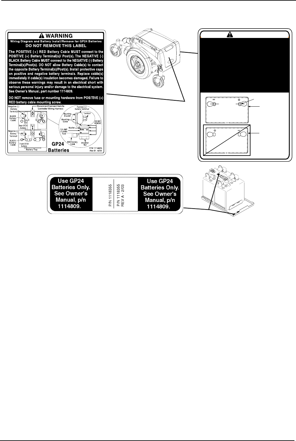
Wheelchairs with GP24 Batteries
WARNING
USE this
battery
terminal
configuration
Positive
Terminal
Negative
Terminal
Positive
Terminal
Negative
Terminal
P/N 1114848 Rev A - 2/03
Cross Hole
DO NOT use
this battery
terminal
configuration
GP24 batteries with terminal configuration
(negative on the left and positive on the right)
as shown MUST be used. GP24 batteries that
have the reverse terminal configuration MUST
not be used. Terminals MUST have a cross
hole located as shown for proper battery
connection. See Owner's Manual, part number
1114809. These recommendations MUST be
followed otherwise injury and damage may
occur.

TYPICAL PRODUCT PARAMETERS
TDX™ SP 14 Part No 1143190
TYPICAL PRODUCT PARAMETERS
BASE LENGTH: 35.25 inches
OVERALL WIDTH OF BASE:
TDS SP WITH TWO 22NF BATTERIES:
TDX SP WITH TWO GP24 BATTERIES OR
WITH THREE 22NF BATTERIES:
24 inches without joystick
25.5 inches without joystick
OVERALL HEIGHT
WITH ASBA SEAT:
WITH VAN SEAT:
WITH FORMULA CG TILT ONLY:
WITH ELEVATING ASBA SEAT:
35.5 to 39.5 inches
38 inches (with head rest), 45 inches (with head rest)
36.5 to 40.5 inches
35.5 to 41.5 inches
OVERALL LENGTH
WITH CENTER MOUNT FRONT RIGGING:
WITHOUT FRONT RIGGINGS:
42.9 inches @ 0°
35.25 inches
WEIGHT (BASE ONLY)
WITHOUT 22NF BATTERIES:
WITH TWO 22NF BATTERIES:
WITHOUT GP24 BATTERIES:
WITH TWO GP24 BATTERIES:
WITH TRANSPORT READY OPTION:
123 lbs
221 lbs
158 lbs
260 lbs
Add 10 lbs
MOTOR: 4 Pole, HD 4 Pole
DRIVE AXLE: Non-adjustable
DRIVE WHEELS/TIRES: 14 x 3-inch Foam Filled or Pneumatic (Standard)
CASTERS: 6 x 2-inch, Semi-pneumatic with Precision Sealed Bearings
CASTER FORKS: Two side fork (Standard), One sided fork (Optional)
BATTERY REQUIREMENTS: Use MK p/n M24SLDG or p/n M22NFSLDG batteries only.
FOOTRESTS: Telescoping Front Rigging Supports,
2-inch and 4-inch long Pivot Slide Tube
SEAT TILT ANGLE ADJUSTMENT: Adjustable (0° to 10°)
*WEIGHT LIMITATION
WITH ASBA SEAT:
WITH ASBA JR. SEAT
WITH VAN SEAT:
WITH FORMULA™ CG POWERED SEATING:
WITH ELEVATING ASBA SEAT:
4 POLE
Up to 300 lbs
Up to 150 lbs
Up to 300 lbs
Up to 300 lbs
Up to 300 lbs
HD 4 POLE
Up to 400 lbs
N/A
Up to 400 lbs
Up to 400 lbs
N/A
NOTE:Alldimensionsare±.50inchesunlessotherwiseindicated.
*NOTE:Weightlimitationistotalweight(userweightplusanyadditionalitemsthattheuser
mayrequire[backpack,etc.]).Example:Ifweightlimitationofthewheelchairis300lbsand
additionalitemsequal25lbs,subtract25lbsfrom300lbs.Thismeansthemaximumweight
limitationoftheuseris275lbs.

SECTION 1—GENERAL GUIDELINES
Part No 1143190 15 TDX™ SP
SECTION 1—GENERAL GUIDELINES
WARNING
SECTION 1 - GENERAL GUIDELINES contains important information for the safe
operation and use of this product. DO NOT use this product or any available
optional equipment without first completely reading and understanding these
instructions and any additional instructional material such as Owner’s Manuals,
Service Manuals or Instruction Sheets supplied with this product or optional
equipment. If you are unable to understand the Warnings, Cautions or Instructions,
contact a healthcare professional, dealer or technical personnel before attempting
to use this equipment - otherwise, injury or damage may occur.
Repair or Service Information
Set‐upoftheElectronicsControlUnitistobeperformedonlybyaqualifiedtechnician.
Thefinaladjustmentsofthecontrollermayaffectotheractivitiesofthewheelchair.
Damagetotheequipmentcouldoccurifimproperlyset‐uporadjusted.
Exceptforprogramming,DONOTserviceoradjustthewheelchairwhileoccupied,
unlessotherwisenoted.
Apinchpointexistsbetweenheadtubecapandwalkingbeam.
Apinchpointexistsbetweenwalkingbeam/headtubecapandtelescopingtubewhen
TDXisatthelowestseattofloorheight.
Beforeadjusting,repairingorservicingthewheelchair,ALWAYSturnthewheelchair
powerOff,otherwise,injuryordamagemayoccur.
Invacareproductsarespecificallydesignedandmanufacturedforuseinconjunctionwith
Invacareaccessories.Accessoriesdesignedbyothermanufacturershavenotbeentested
byInvacareandarenotrecommendedforusewithInvacareproducts.
Transportreadypackagesarenotretrofittabletoexistingmodelsandarenotfield
serviceable.
BatteryretentionbracketsMUSTbeinstalledatalltimes.Otherwise,thewheelchairwill
notbeWC/19compliant.RefertoRemoving/InstallingtheBatteriesFrom/Intothe
Wheelchaironpage 57.
Wheelchairsshouldbeexaminedduringmaintenanceforsignsofcorrosion(water
exposure,incontinence,etc.).Electricalcomponentsdamagedbycorrosionshouldbe
replacedIMMEDIATELY.
Wheelchairsthatareusedbyincontinentusersand/orarefrequentlyexposedtowater
mayrequirereplacementofelectricalcomponentsmorefrequently.
Foroptimumperformance,replacegas‐lockingcylindersevery2years.

SECTION 1—GENERAL GUIDELINES
TDX™ SP 16 Part No 1143190
Operation Information
Performanceadjustmentsshouldonlybemadebyprofessionalsofthehealthcarefieldor
personsfullyconversantwiththisprocessandthedriverʹscapabilities.Incorrectsettings
couldcauseinjurytothedriver,bystanders,damagetothewheelchairandto
surroundingproperty.
Afterthewheelchairhasbeenset‐up/adjusted,checktomakesurethatthewheelchair
performstothespecificationsenteredduringtheset‐upprocedure.Ifthewheelchairdoes
NOTperformtospecifications,turnthewheelchairOffimmediatelyandreenterset‐up
specifications.Repeatthisprocedureuntilthewheelchairperformstospecifications.
DONOTleavethepowerbuttonOnwhenenteringorexitingyourwheelchair.
DONOTattempttodriveovercurbsorobstaclesgreaterthan3inches.Doingsomay
causeyourwheelchairtoturnoverandcausebodilyharmordamagetothewheelchair.
ALWAYSstopbeforeclimbinganobstacle.Approachslowlyuntilcasterscontactthe
obstacle.ApplypowerandtheactionoftheSureStepfeaturewillliftthecastersoverthe
obstacle.Weightistransferredtothedrivewheelsprovidingtractionandmotorstrength
topowerthewheelchairovertheobstacle.
DONOToperateonroads,streetsorhighways.
DONOTclimb,goupordownrampsortraverseslopesgreaterthan9°.
DONOTattempttomoveupordownaninclinewithwater,iceoroilfilm.
DONOTstandontheframeofthewheelchair.
DOdetermineandestablishyourparticularsafetylimitsbypracticingbending,reaching
andtransferringactivitiesinthepresenceofaqualifiedhealthcareprofessionalbefore
attemptingactiveuseofthewheelchair.
DONOTattempttoreachobjectsifyouhavetomoveforwardinyourseat.
DONOTattempttoreachobjectsifyouhavetopickthemupfromthefloorbyreaching
betweenyourknees.
DONOTleanoverthetopofthebackupholsterytoreachobjectsbehindyou,asthismay
causethewheelchairtotipover.
ALWAYSshiftyourweightinthedirectionyouareturning.DONOTshiftyourweight
intheoppositedirectionoftheturn.Shiftingyourweightintheoppositedirectionofthe
turnmaycausetheinsidedrivewheeltolosetractionandthewheelchairtotipover.
DONOTshiftyourweightorsittingpositiontowardthedirectionyouarereachingasthe
wheelchairand/orseatingsystem(ifany)maytipover.
DONOTuseanescalatortomoveawheelchairbetweenfloors.Seriousbodilyinjurymay
occur.
DONOTusethefootplatesasaplatform.Whengettinginoroutofthewheelchair,make
surethatthefootplatesareintheupwardpositionorswingfootreststowardstheoutside
ofthewheelchair.
NEVERleaveanunoccupiedwheelchairunattendedonanincline.

SECTION 1—GENERAL GUIDELINES
Part No 1143190 17 TDX™ SP
DONOTattempttostopamovingwheelchairwiththewheellocks.Wheellocksarenot
brakes.
DONOTattempttoliftthewheelchairbyanyremovable(detachable)parts.Liftingby
meansofanyremovable(detachable)partsofthewheelchairmayresultininjurytothe
userordamagetothewheelchair.
DONOTovertightenhardwareattachingtotheframe.Thiscouldcausedamagetothe
frametubing.
ALWAYSkeephandsandfingersclearofmovingpartstoavoidinjury.
ALWAYSwearyourseatpositioningstrap.Theseatpositioningstrapisapositioningbelt
ONLY.Itisnotdesignedforuseasasafetydevicewithstandinghighstressloadssuchas
autooraircraftsafetybelts.Ifsignsofwearappear,beltMUSTbereplacedimmediately.
ALWAYSturnthewheelchairpoweroffandengagethemotorlocks/clutchestoprevent
thewheelsfrommovingbeforeattemptingtotransferinoroutofthewheelchair.Also
makesureeveryprecautionistakentoreducethegapdistance.Alignbothcastersparallel
withtheobjectyouaretransferringonto.
DONOTusewithabrokenormissingjoystickknob.
DONOTuseifjoystickdoesnotspringbacktotheneutralpositionorbecomesstickyor
sluggish.
DONOTuseifjoystickbootistornordamaged.
ALWAYScheckfoamgripsforloosenessbeforeusingthewheelchair.Ifloose,contacta
qualifiedtechnicianforinstructions.
ALWAYSengagebothwheellocksandreducethegapdistancebeforetransferringtoand
fromthewheelchair.Turnallcastersparalleltotheobjectyouaretransferringonto.
Avoidstoringorusingthewheelchairnearopenflameorcombustibleproducts.Serious
injuryordamagetopropertymayresult.
DONOTengageordisengagethemotorlocksuntilthepowerisintheoffposition.
Wheelchairs with TRRO or TRBKTS Only
OnlyusethetransportbracketsincludedwithTRROandTRBKTSforthepurposes
describedinthismanual.
Tire Pressure
DONOTuseyourwheelchairunlessithasthepropertirepressure(P.S.I.).DONOT
overinflatethetires.Failuretofollowtheserecommendationsmaycausethetireto
explodeandcausebodilyharm.Therecommendedtirepressureislistedonthesidewall
ofthetire.

SECTION 1—GENERAL GUIDELINES
TDX™ SP 18 Part No 1143190
Electrical
Grounding Instructions
DONOT,underanycircumstances,cutorremovetheroundgroundingprongfromany
plugusedwithorforInvacareproducts.Somedevicesareequippedwiththree‐prong
(grounding)plugsforprotectionagainstpossibleshockhazards.Whereatwo‐prongwall
receptacleisencountered,itisthepersonalresponsibilityandobligationofthecustomer
tocontactaqualifiedelectricianandhavethetwo‐prongreceptaclereplacedwitha
properlygroundedthree‐prongwallreceptacleinaccordancewiththeNationalElectrical
Code.Ifyoumustuseanextensioncord,useonlyathree‐wireextensioncordhavingthe
sameorhigherelectricalratingasthedevicebeingconnected.Inaddition,Invacarehas
placedRED/ORANGEwarningtagsonsomeequipment.DONOTremovethesetags.
Batteries
Thewarrantyandperformancespecificationscontainedinthismanualarebasedonthe
useofdeepcyclegelcellbatteries.Invacarestronglyrecommendstheiruseasthepower
sourceforthisunit.
Carefullyreadbattery/batterychargerinformationpriortoinstalling,servicingor
operatingyourwheelchair.
Charging Batteries
DANGER
When using an extension cord, use only a three wire extension cord having at least
16 AWG (American Wire Gauge) wire and the same or higher electrical rating as
the device being connected. Use of improper extension cord could result in risk of
fire and electric shock. Three prong to two prong adapters should not be used. Use
of three prong adapters can result in improper grounding and present a shock haz-
ard to the user.
NEVERattempttorechargethebatteriesbyattachingcablesdirectlytothebattery
terminals.
DONOTattempttorechargethebatteriesandoperatethewheelchairatthesametime.
DONOToperatewheelchairwithextensioncordattachedtotheACcable.
DONOTattempttorechargethebatterieswhenthewheelchairhasbeenexposedtoany
typeofmoisture.
DONOTattempttorechargethebatterieswhenthewheelchairisoutside.
DONOTsitinthewheelchairwhilechargingthebatteries.
READandCAREFULLYfollowthemanufacturer’sinstructionsforeachcharger
(suppliedorpurchased).Ifcharginginstructionsarenotsupplied,consultaqualified
technicianforproperprocedures.
Ensurethepinsoftheextensioncordplugarethesamenumber,size,andshapeasthose
onthecharger.

SECTION 1—GENERAL GUIDELINES
Part No 1143190 19 TDX™ SP
DONOTunderanycircumstancescutorremovetheroundgroundingplugfromthe
chargerACcableplugortheextensioncordplug.
Rain Test
InvacarehastesteditspowerwheelchairsinaccordancewithISO7176“RainTest”.This
providestheenduserorhis/herattendantsufficienttimetoremovehis/herpower
wheelchairfromarainstormandretainwheelchairoperation.
DONOTleavepowerwheelchairinarainstormofanykind.
DONOTusepowerwheelchairinashower.
DONOTleavepowerwheelchairinadampareaforanylengthoftime.
Directexposuretorainordampnesswillcausethewheelchairtomalfunctionelectrically
andmechanically;maycausethewheelchairtoprematurelyrustormaydamagethe
upholstery.
Checktoensurethatthebatterycoversaresecuredinplace,joystickbootisNOTtornor
crackedwherewatercanenterandthatallelectricalconnectionsaresecureatalltimes.
DONOTuseifthejoystickbootistornorcracked.Ifthejoystickbootbecomestornor
cracked,replaceIMMEDIATELY.
Weight Training
InvacareDOESNOTrecommendtheuseofitswheelchairsasaweighttraining
apparatus.InvacarewheelchairshaveNOTbeendesignedortestedasaseatforanykind
ofweighttraining.Ifoccupantusessaidwheelchairasaweighttrainingapparatus,
INVACARESHALLNOTBELIABLEFORBODILYINJURYANDTHEWARRANTYIS
VOID.
Weight Limitation
RefertoTypicalProductParametersforTypicalProductParametersonpage 14to
determinetheweightlimit(totalcombinedweightofuserandanyattachments)ofyour
wheelchairmodel.DONOTexceedthelimit‐otherwise,injuryordamagemayresult.

SECTION 2—EMI INFORMATION
TDX™ SP 20 Part No 1143190
SECTION 2—EMI INFORMATION
WARNING
CAUTION: IT IS VERY IMPORTANT THAT YOU READ THIS INFORMATION
REGARDING THE POSSIBLE EFFECTS OF ELECTROMAGNETIC
INTERFERENCE ON YOUR POWERED WHEELCHAIR.
Electromagnetic Interference (EMI) From Radio Wave Sources
Powered wheelchairs and motorized scooters (in this text, both will be referred to
as powered wheelchairs) may be susceptible to electromagnetic interference (EMI),
which is interfering electromagnetic energy (EM) emitted from sources such as
radio stations, TV stations, amateur radio (HAM) transmitters, two way radios, and
cellular phones. The interference (from radio wave sources) can cause the powered
wheelchair to release its brakes, move by itself, or move in unintended directions. It
can also permanently damage the powered wheelchair's control system. The
intensity of the interfering EM energy can be measured in volts per metre (V/m).
Each powered wheelchair can resist EMI up to a certain intensity. This is called its
"immunity level." The higher the immunity level, the greater the protection. At this
time, current technology is capable of achieving at least a 20 V/m immunity level,
which would provide useful protection from the more common sources of radiated
EMI.
There are a number of sources of relatively intense electromagnetic fields in the
everyday environment. Some of these sources are obvious and easy to avoid.
Others are not apparent and exposure is unavoidable. However, we believe that by
following the warnings listed below, your risk to EMI will be minimized.
The sources of radiated EMI can be broadly classified into three types:
1) Hand-held Portable transceivers (transmitters-receivers with the antenna
mounted directly on the transmitting unit. Examples include: citizens band (CB)
radios, "walkie talkie", security, fire and police transceivers, cellular telephones,
and other personal communication devices).
NOTE: Some cellular telephones and similar devices transmit signals while they are ON,
even when not being used.
2) Medium-range mobile transceivers, such as those used in police cars, fire trucks,
ambulances and taxis. These usually have the antenna mounted on the outside of
the vehicle; and
3) Long-range transmitters and transceivers, such as commercial broadcast
transmitters (radio and TV broadcast antenna towers) and amateur (HAM)
radios.
NOTE: Other types of hand-held devices, such as cordless phones, laptop computers,
AM/FM radios, TV sets, CD players, cassette players, and small appliances, such as elec-
tric shavers and hair dryers, so far as we know, are not likely to cause EMI problems to
your powered wheelchair.

SECTION 2—EMI INFORMATION
Part No 1143190 21 TDX™ SP
WARNING
Powered Wheelchair Electromagnetic Interference (EMI)
Because EM energy rapidly becomes more intense as one moves closer to the
transmitting antenna (source), the EM fields from hand-held radio wave sources
(transceivers) are of special concern. It is possible to unintentionally bring high
levels of EM energy very close to the powered wheelchair's control system while
using these devices. This can affect powered wheelchair movement and braking.
Therefore, the warnings listed below are recommended to prevent possible
interference with the control system of the powered wheelchair.
Electromagnetic interference (EMI) from sources such as radio and TV stations,
amateur radio (HAM) transmitters, two-way radios, and cellular phones can affect
powered wheelchairs and motorized scooters. Also, the electronics used in our
powered wheelchair can generate a low level of electromagnetic interference,
which however will remain within the tolerances permitted by law.
FOLLOWING THE WARNINGS LISTED BELOW SHOULD REDUCE THE
CHANCE OF UNINTENDED BRAKE RELEASE OR POWERED WHEELCHAIR
MOVEMENT WHICH COULD RESULT IN SERIOUS INJURY.
1) Do not operate hand-held transceivers (transmitters receivers), such as citizens
band (CB) radios, or turn ON personal communication devices, such as cellular
phones, while the powered wheelchair is turned ON;
2) Be aware of nearby transmitters, such as radio or TV stations, and try to avoid
coming close to them;
3) If unintended movement or brake release occurs, turn the powered wheelchair
OFF as soon as it is safe;
4) Be aware that adding accessories or components, or modifying the powered
wheelchair, may make it more susceptible to EMI (NOTE: There is no easy way
to evaluate their effect on the overall immunity of the powered wheelchair); and
5) Report all incidents of unintended movement or brake release to the powered
wheelchair manufacturer, and note whether there is a source of EMI nearby.
Important Information
1) 20 volts per metre (V/m) is a generally achievable and useful immunity level
against EMI (as of May 1994) (the higher the level, the greater the protection);
2) This device has been tested to a radiated immunity level of 20 volts per meter.
3) The immunity level of the product is unknown.
Modification of any kind to the electronics of this wheelchair as manufactured by
Invacare may adversely affect the EMI immunity levels.

SECTION 3—SAFETY/HANDLING OF WHEELCHAIRS
TDX™ SP 22 Part No 1143190
SECTION 3—SAFETY/HANDLING OF
WHEELCHAIRS
“SafetyandHandling”ofthewheelchairrequiresthecloseattentionofthewheelchair
useraswellastheassistant.Thismanualpointsoutthemostcommonproceduresand
techniquesinvolvedinthesafeoperationandmaintenanceofthewheelchair.Itis
importanttopracticeandmasterthesesafetechniquesuntilyouarecomfortablein
maneuveringaroundthefrequentlyencounteredarchitecturalbarriers.
Usethisinformationonlyasa“basic”guide.Thetechniquesthatarediscussedonthe
followingpageshavebeenusedsuccessfullybymany.
Individualwheelchairusersoftendevelopskillstodealwithdailylivingactivitiesthat
maydifferfromthosedescribedinthismanual.Invacarerecognizesandencourageseach
individualtotrywhatworksbestforhim/herinovercomingarchitecturalobstaclesthat
theymayencounter,howeverallwarningsandcautionsgiveninthismanualMUSTbe
followed.Techniquesinthismanualareastartingpointforthenewwheelchairuserand
assistantwith“safety”asthemostimportantconsiderationforall.
Stability and Balance
WARNING
ALWAYS wear your seat positioning strap. The seat positioning strap is a
positioning belt ONLY. It is not designed for use as a safety device withstanding high
stress loads such as auto or aircraft safety belts. If signs of wear appear, belt MUST
be replaced immediately.
DO NOT climb, go UP or DOWN ramps or traverse slopes greater than 9°.
Invacare strongly recommends proceeding down ramps or slopes slowly to avoid
hard braking or sudden stops.
DO NOT leave elevating legrests in the fully extended position when proceeding
down ramps or slopes.
Be aware that carrying heavy objects on your lap while occupying the wheelchair
may adversely affect the stability of the wheelchair, resulting in serious bodily injury
to the user, damage to the wheelchair and surrounding property.
This wheelchair has been designed to accommodate one individual. If more than
one individual occupies the wheelchair this may adversely affect the stability of the
wheelchair, resulting in serious bodily injury to the user and passenger and damage
to the wheelchair and surrounding property.

SECTION 3—SAFETY/HANDLING OF WHEELCHAIRS
Part No 1143190 23 TDX™ SP
WARNING
DO NOT attempt to reach objects if you have to move forward in the seat or pick
them up from the floor by reaching down between your knees.
Many activities require the wheelchair user to reach, bend and transfer in and out of
the wheelchair. These movements will cause a change to the normal balance,
center of gravity, and weight distribution of the wheelchair. To determine and
establish your particular safety limits, practice bending, reaching and transferring
activities in several combinations in the presence of a qualified healthcare
professional before attempting active use of the wheelchair.
Proper positioning is essential for your safety. When reaching, leaning, bending or
bending forward, it is important to use the casters as a tool to maintain stability and
balance.
Toassurestabilityandproperoperationofyourwheelchair,youmustatalltimes
maintainproperbalance.Yourwheelchairhasbeendesignedtoremainuprightand
stableduringnormaldailyactivitiesaslongasyouDONOTmovebeyondthecenterof
gravity.DONOTleanforwardoutofthewheelchairanyfurtherthanthelengthofthe
armrests.Makesurethecastersarepointingintheforwardpositionwheneveryoulean
forward.Thiscanbeachievedbyadvancingthewheelchairandthenreversingitina
straightline.
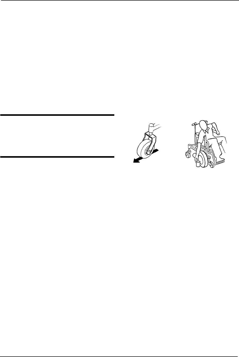
Coping with Everyday Obstacles
NOTE:Forthisprocedure,refertoFIGURE 3.1
Copingwiththeirritationofeverydayobstaclescanbesomewhatalleviatedbylearning
howtomanageyourwheelchair.Keepinmindyourcenterofgravitytomaintainstability
andbalance.
Whilethewalkingbeamallowsyoutotraverseuptoa3‐inchbumporthreshold,
stoppingafterthewheelscrossthebumpposesaproblem.Thewheelchaircannotreverse
overthebumpatthispoint.Continueforwardandthenturnaround.
WhiletheTDXisdesignedforuseprimarilyinandaroundthehome,theprovidershould
determinewhetherthiswheelchairissuitablefortheactualenvironmentinwhichthe
wheelchairwillbeused.
NOTE:DONOTgodownarampatfullspeed.
Someseat/backpositionswillcausethe
wheelchairtofeelunstable.
CAUTION
Be aware of the condition of the ramp.
Traction will be diminished/nonexistent
on a slippery surface. Proceed with
caution. FIGURE 3.1 Coping with Everyday
Obstacles
Bump/Threshold
SECTION 3—SAFETY/HANDLING OF WHEELCHAIRS
TDX™ SP 24 Part No 1143190
A Note to Wheelchair Assistants
Whenassistancetothewheelchairuserisrequired,remembertousegoodbody
mechanics.Keepyourbackstraightandbendyourkneeswhenevertiltingwheelchairor
traversingcurbsorotherimpediments.
Also,beawareofdetachablepartssuchasarmsorlegrests.ThesemustNEVERbeused
tomovethewheelchairorasliftingsupports,astheymaybeinadvertentlyreleased,
resultinginpossibleinjurytotheuserand/orassistant(s).
Whenlearninganewassistancetechnique,haveanexperiencedassistanthelpyoubefore
attemptingitalone.
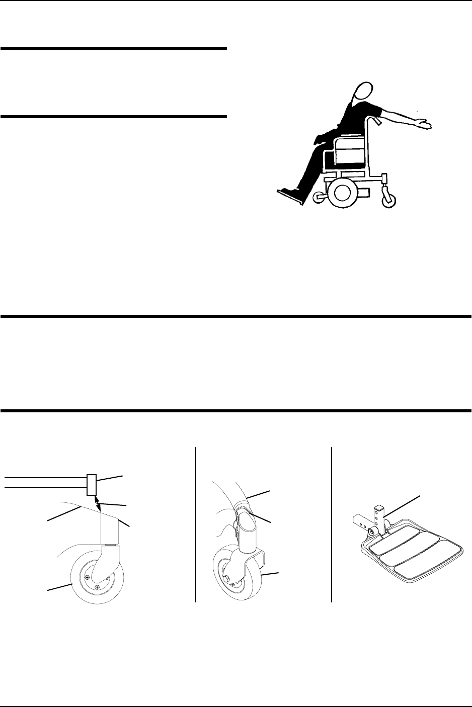
Reaching, Leaning andBending - Forward
WARNING
DO NOT attempt to reach objects if
you have to move forward in the seat or
pick them up from the floor by reaching
down between your knees.
NOTE:Forthisprocedure,referto
FIGURE 3.2.
Positionthecasterssothattheyare
extendedawayfromthedrivewheelsand
engagewheellocks/motorlocks/clutches.
FIGURE 3.2 Reaching, Leaning and Bending
- Forward
SECTION 3—SAFETY/HANDLING OF WHEELCHAIRS
Part No 1143190 25 TDX™ SP
Reaching, Bending - Backward
WARNING
DO NOT lean over the top of the back
upholstery. This will change your center
of gravity and may cause you to tip over.
NOTE:Forthisprocedure,referto
FIGURE 3.3.
Positionwheelchairascloseaspossibleto
thedesiredobject.Positionthecastersso
thattheyareextendedawayfromthedrive
wheelstocreatethelongestpossible
wheelbase.Reachbackonlyasfarasyour
armwillextendwithoutchangingyour
sittingposition.
FIGURE 3.3 Reaching, Bending - Backward
Pinch Points
WARNING
A pinch point exists between head tube cap and walking beam (Detail “A”).
A pinch point exists between walking beam/head tube cap and telescoping tube
when TDX SP is at the lowest seat to floor height (Detail “B”).
Pinch point may occur when rotating the footboard assembly (Detail “C”).
NOTE:Forthisprocedure,refertoFIGURE 3.4.
FIGURE 3.4 Pinch Points
Pinch Point
Headtube
Cap
Front
Caster
Telescoping
Tube
Walking
Beam
Walking
Beam
Headtube
Cap
Front
Caster
Pinch
Point
DETAIL “A” DETAIL “B” DETAIL “C”

SECTION 3—SAFETY/HANDLING OF WHEELCHAIRS
TDX™ SP 26 Part No 1143190
Stairways
WARNING
DO NOT attempt to move an occupied power wheelchair between floors using a
stairway. Use an elevator to move an occupied power wheelchair between floors. If
moving a power wheelchair between floors by means of a stairway, the occupant
MUST be removed and transported independently of the power wheelchair.
Extreme caution is advised when it is necessary to move an unoccupied power
wheelchair up or down the stairs. Invacare recommends using two assistants and
making thorough preparations. Make sure to use ONLY secure, non-detachable
parts for hand-hold supports.
DO NOT attempt to lift the wheelchair by any removable (detachable) parts.
Lifting by means of any removable (detachable) parts of a wheelchair may result in
injury to the user or damage to the wheelchair.
The weight of the wheelchair without the user and without batteries is between 166
and 322 lbs. Use proper lifting techniques (lift with your legs) to avoid injury.
Followthisprocedureformovingthewheelchairbetweenfloorswhenanelevatoris
NOTavailable:
NOTE:Whenusingastairwaytomovethewheelchairandanyaccessories,moveallwheelchair
componentsawayfromthestairwaypriortoreassembly.
1. Removetheoccupantfromthewheelchair.
2. Removethebatteriesfromwheelchair.RefertoBatteriesonpage 53.
3. Bendyourkneesandkeepyourbackstraight.
4. Usingnon‐removable(non‐detachable)partsofthewheelchair,liftthewheelchairoff
ofthegroundandtransferthewheelchairupordownthestairs.
5. Thewheelchairshouldnotbelowereduntilthelaststairhasbeennegotiatedandthe
wheelchairhasbeencarriedawayfromthestairway.
WARNING: ESCALATORS
DO NOT use an escalator to move a wheelchair between floors. Serious bodily
injury may occur.
SECTION 3—SAFETY/HANDLING OF WHEELCHAIRS
Part No 1143190 27 TDX™ SP
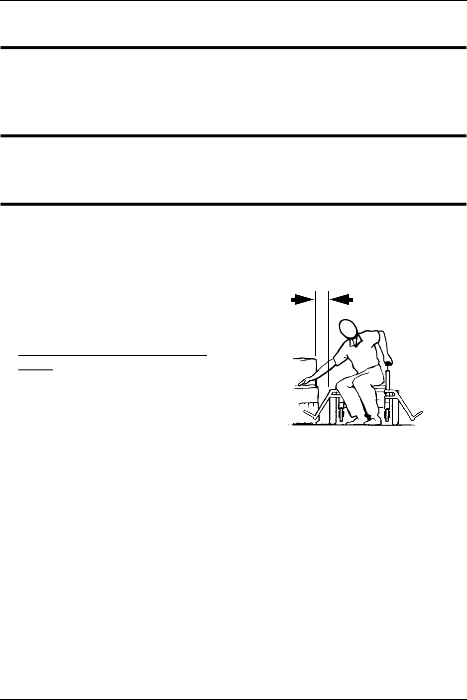
Transferring To and From Other Seats
WARNING
ALWAYS turn the wheelchair power OFF and engage the motor locks/clutches to
prevent the wheels from moving before attempting to transfer in or out of the
wheelchair. Also make sure every precaution is taken to reduce the gap distance.
Align both casters parallel with the object you are transferring onto.
CAUTION
When transferring, position yourself as far back as possible in the seat. This will
prevent broken screws, damaged upholstery and the possibility of the wheelchair
tipping forward.
NOTE:Forthisprocedure,refertoFIGURE 3.5.
NOTE:Adequatemobilityandupperbodystrengthisrequiredtoperformthisactivity
independently.
1. Positionthewheelchairascloseas
possiblealongsidetheseattowhich
youaretransferring,withthecasters
alignedparallelwiththeobject.
2. Engagemotorlocks.Referto
Disengaging/EngagingMotorLock
Leversonpage 48.
3. Shiftbodyweightintoseatwith
transfer.
NOTE:Duringindependenttransfer,littleor
noseatplatformwillbebeneathyou.Usea
transferboardifatallpossible. FIGURE 3.5 Transferring To and From
Other Seats
Minimize Gap Distance

SECTION 4—SAFETY INSPECTION/TROUBLESHOOTING
TDX™ SP 28 Part No 1143190
SECTION 4—SAFETY INSPECTION/
TROUBLESHOOTING
NOTE:Everysixmonthstakeyourwheelchairtoaqualifiedtechnicianforathoroughinspection
andservicing.Regularcleaningwillreveallooseorwornpartsandenhancethesmoothoperation
ofyourwheelchair.Tooperateproperlyandsafely,yourwheelchairmustbecaredforjustlikeany
othervehicle.Routinemaintenancewillextendthelifeandefficiencyofyourwheelchair.
Initialadjustmentsshouldbemadetosuityourpersonalbodystructureneedsand
preference.Thereafterfollowthesemaintenanceprocedures:
Safety Inspection Checklists
Inspect/Adjust Initially
CAUTION
As with any vehicle, the wheels and tires should be checked periodically for cracks
and wear, and should be replaced.
❑Ensurewheelchairrollsstraight(noexcessivedragorpulltooneside).
❑Inspectallfasteners.
❑InspectTRRO/TRBKTSfastenersandhardware.
❑Ensureclothingguardsaresecure.
❑Armsaresecurebuteasytoreleaseandadjustmentleversengageproperly.
❑Adjustableheightarmsoperateandlocksecurely.
❑Upholsteryhasnorips.
❑Armrestpadsitsflushagainstarmtube.
❑Axlenutandwheelmountingnutsaresecureondrivewheels.
❑Noexcessivesidemovementorbindingwhendrivewheelsareliftedandspunwhen
disengaged(free‐wheeling).
❑Ensurethatcastersarefreeofdebris.
❑Wheels/castershavepropertensionwhenwheels/castersarespun(whenfree‐
wheeling).Wheels/castersshouldcometoagradualstop.
❑Loosen/tightencasterlocknutifwheelwobblesnoticeablyorbindstoastop.
❑Ensureallcaster/wheel/fork/headtubefastenersaresecureandnotdamaged/missing.
❑WheellocksDONOTinterferewithtireswhenrolling.
❑Wheellockpivotpointarefreeofwearandlooseness.
❑Wheellocksareeasytoengage.
❑Inspecttiresforflatspotsandwear.

SECTION 4—SAFETY INSPECTION/TROUBLESHOOTING
Part No 1143190 29 TDX™ SP
❑Checkpneumatictiresforproperinflation.
❑Checkcentermountfrontriggingsforworn/frayedbeltsand/orloosefasteners.If
found,replacetheseitems.
❑Checkthatalllabelsarepresentandlegible.Replaceifnecessary.
❑Inspectlockinggascylinders.
❑CheckthatcablesareroutedandsecuredproperlytoensurethatcablesDONOT
becomeentangledanddamagedduringnormaloperationofseatingsystem.
Inspect/Adjust Weekly
CAUTION
As with any vehicle, the wheels and tires should be checked periodically for cracks
and wear, and should be replaced.
❑Wheels/castershavepropertensionwhenwheels/castersarespun(whenfree‐
wheeling).Wheels/castersshouldcometoagradualstop.
❑Ensurethatcastersarefreeofdebris.
❑Ensureallcaster/wheel/fork/headtubefastenersaresecureandnotdamaged/missing.
❑Loosen/tightencasterlocknutifwheelwobblesnoticeablyorbindstoastop.
❑Inspecttiresforflatspotsandwear.
❑WheellocksDONOTinterferewithtireswhenrolling.
❑Wheellockpivotpointarefreeofwearandlooseness.
❑Wheellocksareeasytoengage.
❑Checkpneumatictiresforproperinflation.
❑Inspectallfasteners.
❑InspectTRRO/TRBKTSfastenersandhardware.
❑CheckthatcablesareroutedandsecuredproperlytoensurethatcablesDONOT
becomeentangledanddamagedduringnormaloperationofseatingsystem.
Inspect/Adjust Monthly
❑Axlenutandwheelmountingnutsaresecureondrivewheels.
❑Cleanupholsteryandarmrests.
❑Cleandirtandlintfromaxles.
❑Cleandirtandlintfrombearings.
❑Ensurethatcastersarefreeofdebris.
❑Inspectlockinggascylinders.
❑Inspectmechanicalanti‐diveforfunction.
❑Inspectseatpositioningstrapforanysignsofwear.Ensurebucklelatches.Verify
hardwarethatattachesstraptoframeissecureandundamaged.Replaceifnecessary.

SECTION 4—SAFETY INSPECTION/TROUBLESHOOTING
TDX™ SP 30 Part No 1143190
Inspect/Adjust Periodically
❑Ensurewheelchairrollsstraight(noexcessivedragorpulltooneside).
❑Inspectallfasteners.
❑InspectTRRO/TRBKTSfastenersandhardware.
❑Ensureclothingguardsaresecure.
❑Armsaresecurebuteasytoreleaseandadjustmentleversengageproperly.
❑Adjustableheightarmsoperateandlocksecurely.
❑Upholsteryhasnorips.
❑Armrestpadsitsflushagainstarmtube.
❑Axlenutandwheelmountingnutsaresecureondrivewheels.
❑Wheels/castershavepropertensionwhenwheels/castersarespun(whenfree‐
wheeling).Wheels/castersshouldcometoagradualstop.
❑Ensurethatcastersarefreeofdebris.
❑Inspectfoamhandgripsfordamage.Ifdamaged,havethemreplacedbyaqualified
technician.
❑Inspectmotorbrushesandgearboxcoupling(4pole).
❑Checkcentermountfrontriggingsforworn/frayedbeltsand/orloosefasteners.If
found,replacetheseitems.
❑Checkthatalllabelsarepresentandlegible.Replaceifnecessary.
❑Inspectelectricalcomponentsforsignsofcorrosion.Replaceifcorrodedordamaged.
Inspect/Adjust Every 18 Months
❑Replacemotorbrushesandgearboxcoupling(4pole).
Inspect/Adjust Every 2 Years
❑Foroptimumperformance,replacegas‐lockingcylinders.
Troubleshooting - Mechanical
WHEELCHAIR
VEERS
LEFT/RIGHT
SLUGGISH
TURN/
PERFORMANCE
CASTERS
FLUTTER
SQUEAKS AND
RATTLES
LOOSENESS IN
WHEELCHAIR
WHEELCHAIR 3
WHEELS
SOLUTIONS
X X X If pneumatic, check tires for correct and equal pressure.
X X X X Check for loose stem nuts/bolts.
X X Check that casters contact ground at the same time.
X X If pneumatic, check tires for correct and equal pressure.
SECTION 4—SAFETY INSPECTION/TROUBLESHOOTING
Part No 1143190 31 TDX™ SP
Troubleshooting - Electrical
NOTE:Foradditionaltroubleshootinginformationandexplanationoferrorcodes,refertothe
individualElectronicsManualsuppliedwitheachwheelchair.
SPJ™+, SPJ+ w/PSS or SPJ+ w/ACC Joysticks
Thejoystickinformationgaugeandtheserviceindicatorgiveindicationsofthetypeof
faultorerrordetectedbythecontrolmodule.Whenafaultisdetected,thewheelchair
maystopandnotdrive.TheLEDsontheinformationgaugemayflashinaparticular
patternortheserviceindicatorlightwillflash.Thenumberortypeofflashesindicatesthe
natureoftheerror.Ifmultipleerrorsarefound,onlythefirsterrorencounteredbythe
controlmodulewillbedisplayed.
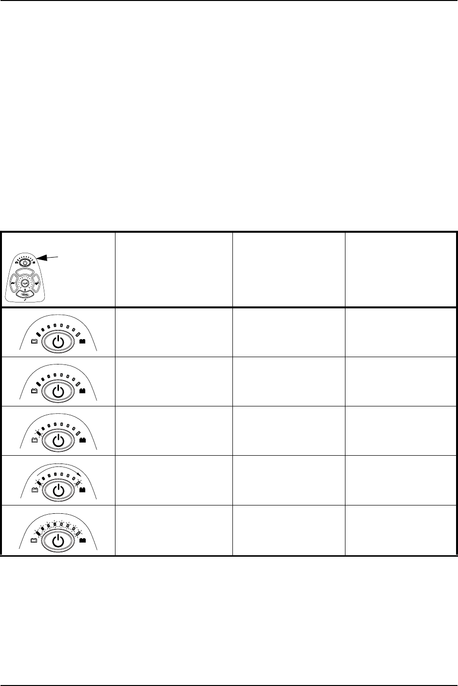
Information Gauge Display Diagnostics
DISPLAY DESCRIPTION DEFINITION COMMENTS
All LEDs are off. Power is off.
All LEDs are on. Power is on. Fewer than three LEDs on
implies reduced battery
charge.
Left RED LED is flashing. Battery charge is low. The batteries should be
charged as soon as possi-
ble.
Left to Right “chase”
alternating with steady
display.
Joystick is in
programming, inhibit and/
or charging mode.
The steady LEDs indicate
the current state of the
battery charge.
All LEDs are flashing slowly. Joystick has detected Out-
of-Neutral-at-Power-Up
mode.
Release the joystick back
to Neutral.
Information
Gauge
Display

SECTION 4—SAFETY INSPECTION/TROUBLESHOOTING
TDX™ SP 32 Part No 1143190
Service Indicator Light Diagnostics
MPJ™+, PSR+, PSF+ Joysticks or Displays
NUMBER
OF
FLASHES
ERROR CODE
DESCRIPTION POSSIBLE SOLUTION
1 User Fault Release joystick to neutral and try again.
2 Battery Fault Charge the batteries. Refer to Charging Batteries on page 62.
Check that battery cables are connected properly. If necessary,
replace batteries. Refer to Replacing Batteries on page 55.
3 Left Motor Fault Contact Invacare/Dealer for service.
4 Right Motor Fault Contact Invacare/Dealer for service.
5 Left Park Brake Fault Contact Invacare/Dealer for service.
6 Right Park Brake Fault Contact Invacare/Dealer for service.
7 Remote Fault Check to make sure joystick is connected properly.
Contact Invacare/Dealer for service.
8 Controller Fault Contact Invacare/Dealer for service.
9 Communications Fault Contact Invacare/Dealer for service.
10 General Fault Contact Invacare/Dealer for service.
11 Incompatible or incorrect
Remote
Wrong type of remote connected. Contact Invacare/Dealer
for service.
SYMPTOM PROBABLE CAUSE SOLUTIONS
SPM L Park Brake Fault or
SPM R Park Brake Fault displays
and wheelchair does not drive.
Motor lock levers disengaged
(Error code E9 or E10).
Engage motor lock levers. Refer to
Disengaging/Engaging Motor Lock
Levers on page 48.
CHARGER PLUGGED IN displays. Battery charger connected
(Error code E28).
Unplug battery charger from the
wheelchair. Refer to Charging Batteries
on page 62.
SPM Battery Fault displays and the
wheelchair does not drive.
Batteries need to be charged
(Error code E14).
Charge batteries. Refer to Charging
Batteries on page 62. If batteries fail to
charge properly, check battery charger
or replace batteries. Refer to Replacing
Batteries on page 55.
JOYSTICK TIMEOUT displays and
the wheelchair does not drive.
Joystick or input device is
disconnected (Error code 32).
Turn off power, reconnect the joystick
of input device and turn power on.
JS REV TOO LARGE
JS FWD TOO LARGE
JS LFT TOO LARGE or
JS RGT TOO LARGE
displays and the wheelchair does not
drive.
The joystick or input device is
sending a value outside of the
reverse, forward, left or right
limits (Error codes E01, E02,
E03 or E04).
Replace joystick or input device.

SECTION 4—SAFETY INSPECTION/TROUBLESHOOTING
Part No 1143190 33 TDX™ SP
NEUTRAL TESTING displays. The joystick neutral test has
failed (Error code E18).
Release the joystick and try to get the
joystick back into the center-most
position.
BAD JOYSTICK CAL VALUES
displays and the wheelchair does not
drive.
The joystick calibration values
are outside of the expected
range (Error code E19).
Recalibrate the joystick (joystick throw
procedure).
SPM NOT CONNECTED The MPJ or Display module is
not communicating with the
control module (Error code
E200).
Check the connections between the
joystick or display and the controller.
Turn the power off and then back on.
Replace the controller if necessary.
SPM Communications Fault
displays and the wheelchair drives
slowly.
The controller has determined a
fault during a previous turn-off
process (Error code E41).
Turn the wheelchair off and back on.
ATTENDANT ACTIVE and
displays.
The Proportional or Digital
Attendant control is active and
can be used to drive the chair
(Error code W05).
This is normal behavior.
Batteries draw excessive current
when charging.
Battery failure.
Electrical malfunction.
Have batteries checked for shorted cell.
Replace if necessary.
Contact Dealer/Invacare for service.
Battery indicator flashes the charge
level is low - immediately after
recharge.
Battery failure.
Malfunctioning battery charger.
Electrical malfunction.
Check batteries for shorted cell.
Replace if necessary.
Contact Dealer/Invacare for Service.
Contact Dealer/Invacare for Service.
Battery indicator flashes the charge
level is low - too soon after being
recharged.
Batteries not charged.
Weak batteries.
Have charger checked.
Replace batteries if necessary. Refer to
Replacing Batteries on page 55.
Motor “chatters” or runs irregular. Electrical malfunction. Contact Dealer/Invacare for Service.
Joystick erratic or does not respond
as desired.
Damaged motor coupling.
Electrical malfunction.
Controller programmed
improperly.
Contact Dealer/Invacare for Service.
Contact Dealer/Invacare for Service.
Contact Dealer/Invacare to have
controller reprogrammed.
Wheelchair does not respond to
commands.
Poor battery terminal
connection.
Have terminals cleaned.
Power indicator off - even after
recharging.
Electrical malfunction. Contact Dealer/Invacare for Service.
SYMPTOM PROBABLE CAUSE SOLUTIONS

SECTION 4—SAFETY INSPECTION/TROUBLESHOOTING
TDX™ SP 34 Part No 1143190
Checking Battery Charge Level
Thefollowing“Do’s”and“Don’ts”areprovidedforyourconvenienceandsafety.
DON’T DO
Don’t perform any installation or maintenance
without first reading this manual.
Read and understand this manual and any service
information that accompanies a battery and charger before
operating the wheelchair.
Don’t perform installation or maintenance of
batteries in an area that could be damaged by
battery spills.
Move the wheelchair to a work area before cleaning
terminals, or opening battery box.
Don’t make it a habit to discharge batteries to
the lowest level.
Recharge as frequently as possible to maintain a high charge
level and extend battery life.
Don’t use randomly chosen batteries or chargers. Follow recommendations in this manual when selecting a
battery or charger.
Don’t put new batteries into service before
charging.
Fully charge a new battery before using.
Don’t tip or tilt batteries. Use a carrying strap to remove, move or install a battery.
Don’t tap on clamps and terminals with tools. Push battery clamps on the terminals. Spread clamps wider if
necessary.
Don’t mismatch your battery and chargers. Use ONLY a GEL charger for a GEL battery.
SECTION 5—WHEELCHAIR OPERATION
Part No 1143190 35 TDX™ SP
SECTION 5—WHEELCHAIR
OPERATION
WARNING
After ANY adjustments, repair or service and before use, make sure that all
attaching hardware is tightened securely - otherwise injury or damage may result.
Set-up of the Electronic Control Unit is to be performed only by a qualified techni-
cian. The final adjustments of the controller may affect other activities of the wheel-
chair. Damage to the equipment could occur under these circumstances.
Operating the Wheelchair
Turning the Power On/Off
NOTE:Forthisprocedure,refertoFIGURE 5.1.
1. ToturnthepowerOn,performoneofthefollowingsteps:
2. TurningthepowerOffcanbeachievedbyperformingoneofthefollowingsteps:
FIGURE 5.1 Turning the Power On/Off
Using the Joystick to Drive the Wheelchair
NOTE:Forthisprocedure,refertoFIGURE 5.2onpage 36.
Thejoystickislocatedonthejoystickhousingandprovidessmoothcontrolofspeedand
direction.Itisequippedwith360degreesofmobilityforeaseofoperation.Thejoystickis
spring‐loaded,andautomaticallyreturnstotheupright(neutral)positionwhenreleased.
Pushingthejoystickinagivendirectioncausesthewheelchairtomoveinthatdirection.
JOYSTICK ACTION
MPJ+ Move the On/Off switch Forward to the On position.
SPJ+ Press the On/Off button.
JOYSTICK ACTION
MPJ+ Move the On/Off switch Back to the Off position.
SPJ+ Press the On/Off button.
MPJ+ Joystick
On/Off
Switch
SPJ+ Joysticks
On/Off
Button

SECTION 5—WHEELCHAIR OPERATION
TDX™ SP 36 Part No 1143190
Thejoystickhasproportionaldrivecontrol,meaningthatthefurtheritispushedfromthe
upright(neutral)position,thefasterthewheelchairmoves.Themaximumspeed,
however,islimitedbythesettingofthespeed‐controlknob.
Toslowthewheelchairtoastop,simplyreleasethejoystick.Thewheelchairhas
automaticspeedanddirectioncompensationtominimizecorrections.
Whenfirstlearningtodrive,selectaslowspeedandtrytodrivethewheelchairasslowly
aspossiblebypushingthejoystickslightlyforward.Thisexercisewillhelpyoulearnto
utilizethefullpotentialoftheproportionalcontrolandallowyoutostartandstop
smoothly.
Todrivethewheelchair,performthefollowing:
1. Adjustspeedcontrolknobtotheappropriatesetting.
2. TurnthepowerOn.RefertoTurningthePowerOn/Offonpage 35.
3. Maneuverthejoystickinthefollowingmanner:
FIGURE 5.2 Using the Joystick to Drive the
Wheelchair
NOTE:Forspecificinformationaboutthejoystickinstalledonthewheelchair,refertooneofthese
procedures:
•SPJ+,MK6i™SPJ+w/PSSandMK6iSPJ+w/ACCJoystickSwitchesandIndicatorson
page 37.
•MPJ+JoystickSwitchesandIndicatorsonpage 39.
MOVEMENT ACTION
FORWARD Push joystick forward, towards
the front of the wheelchair.
REVERSE Pull joystick back, towards the
rear of the wheelchair.
Turn RIGHT Move joystick toward the right
side of the wheelchair.
Turn LEFT Move joystick toward the left side
of the wheelchair.
STOP Release the joystick and the
wheelchair will slow to a stop.
To Move
Right
To Move
Forward
To Move
Left
To Move
Backward
Joystick
Front of
Wheelchair
Rear of
Wheelchair
SECTION 5—WHEELCHAIR OPERATION
Part No 1143190 37 TDX™ SP
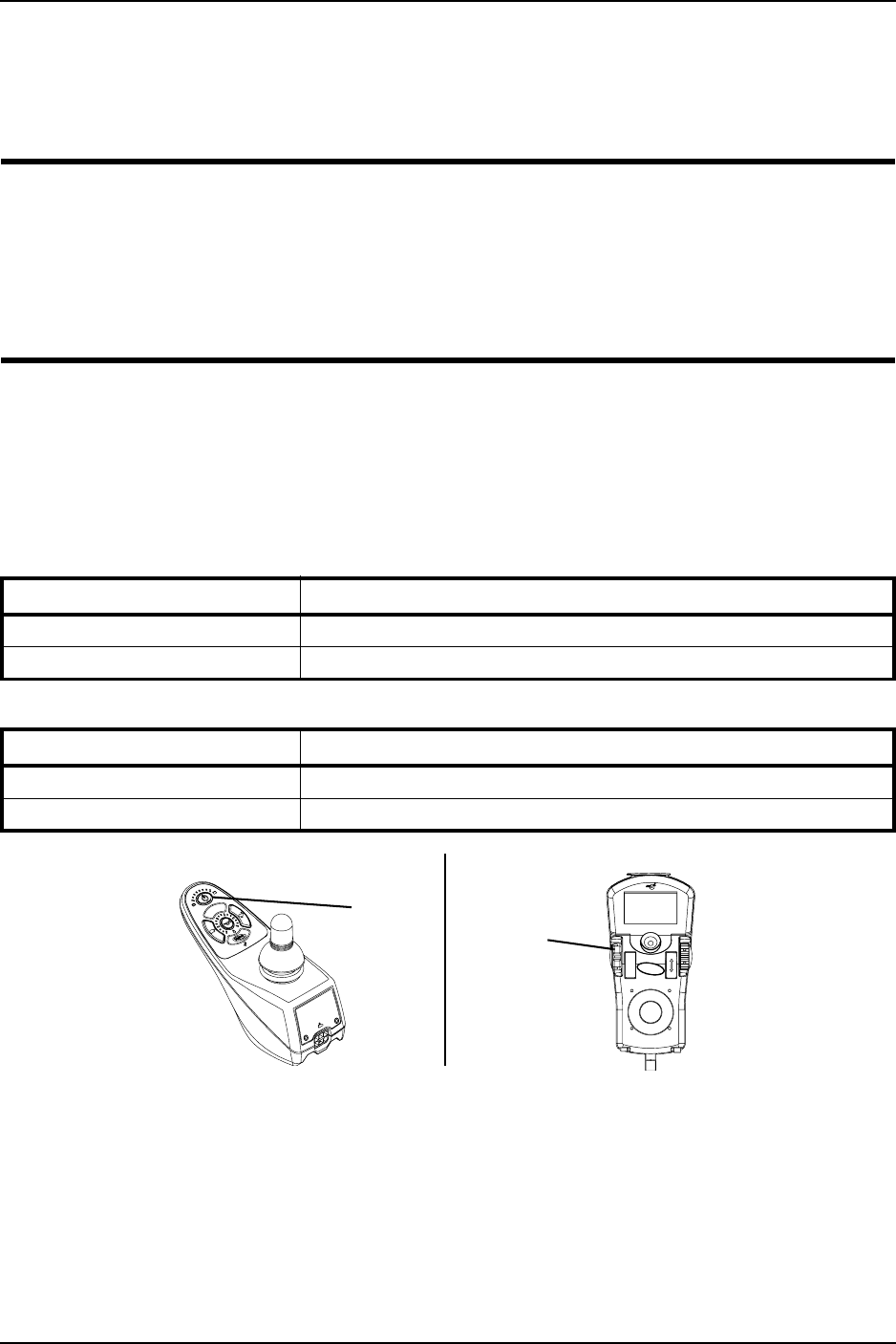
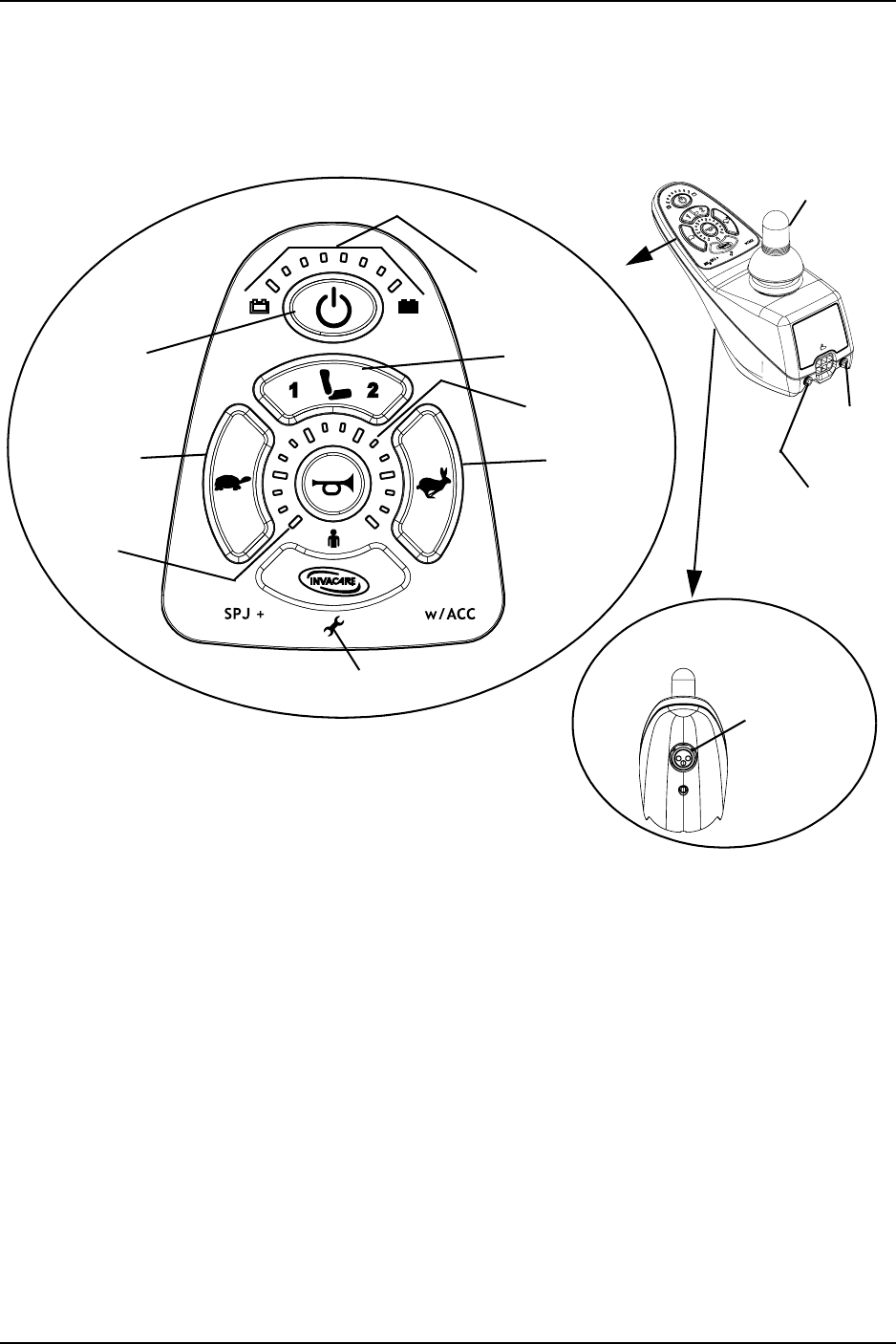
SPJ+, MK6i™ SPJ+ w/PSS and MK6i SPJ+ w/ACC
Joystick Switches and Indicators
NOTE:Forthefollowinginformation,refertoFIGURE 5.3.
FIGURE 5.3 SPJ+, MK6i™ SPJ+ w/PSS and MK6i SPJ+ w/ACC Joystick Switches and Indicators
On/Off Button
Thisbuttonislocatedatthefrontofthejoystickhousing.Itisusedtoturnthewheelchair
OnandOff,toremovethejoystickfromsleepmode(ifprogrammed)andtolockor
unlockthejoystick(ifprogrammed).
Speedometer
Thespeedometerisusedtoshowthemaximumspeed.Theright‐mostLEDindicates
currentmaximumspeedsetting.ThebottomleftGREENLEDflashestoindicatethatthe
joystickisinspeedlimitmode.Speedlimitmodelimitsthedrivespeedtoapre‐
programmedvalue,typicallywhentheseathasbeenelevatedandthewheelchairis
requiredtodriveat20%speed.
On/Off
Button
DETAIL “A” -
FRONT VIEW
Charger/
Programming
Input
Speedometer
Joystick
GREEN
LED
Information
Gauge Display
Service Indicator
Decrease
Speed Button
(Tortoise) Increase
Speed Button
(Hare)
Mode Button*
Additional Input
for Powered
Seating Switch
*NOTE:Themodebuttonisonly
presentonSPJ+w/ACCjoystick.
Not
Active

SECTION 5—WHEELCHAIR OPERATION
TDX™ SP 38 Part No 1143190
Speed Control Buttons
Thespeedcontrolbuttons(tortoisebutton()andharebutton())areusedtosetand
adjustthemaximumspeed.
1. Toadjustthespeed,performoneofthefollowing:
•AdjustSpeedin20%Increments(5SpeedMode)‐Pressthetortoisebutton()
orharebutton()todecrease/increasethespeedin20%increments.Thelarger
barsinthespeedometerwilllight.
•AdjustSpeedinSmallerIncrements(VSPMode)‐Performthefollowingsteps:
i. Pressandholdboththetortoisebutton()andharebutton()untilthe
joystickbeeps.
ii. Performoneofthefollowing:
•Pressthetortoisebutton()orharebutton()todecrease/increasethe
speedin20%increments.Thelargerbarsinthespeedometerwilllight.
•Pressandholdthetortoisebutton()orharebutton()todecrease/
increasethespeedinsmallerincrements.Thesmallerbarsinthe
speedometerwilllight.
Joystick
Thejoystickhasproportionaldrivecontrol,meaningthatthefurtherthejoystickis
pushedfromtheupright(neutral)position,thefasterthewheelchairorseatmoves.Your
topspeed,however,islimitedbytheprogrammedsettings.
Toslowthewheelchairtoastop,simplyreleasethejoystick.Thewheelchairhas
automaticspeedanddirectioncompensationtominimizecorrections.
Charger/Programming Input
Thecharger/programminginputislocatedatthefrontofthejoystickhousing.This
provideseasyaccessforchargingthewheelchairbatteries.Thisportalsoservesasthe
RemoteProgrammerCommunicationconnection.Drivingispreventedwhilethesystem
ischarging.
Service Indicator
TheAMBERserviceindicatorwilllightwhenanerrororfaultoccurs.RefertoService
IndicatorLightDiagnosticsonpage 30foralistingoftheflashcodesandwhatthey
indicate.

SECTION 5—WHEELCHAIR OPERATION
Part No 1143190 39 TDX™ SP
Information Gauge Display
Theinformationgaugedisplayislocatedonthefrontofthejoystickhousingandprovides
thefollowinginformationtotheuseronthestatusofthewheelchair:
1. PowerisOn.
2. Truestate‐of‐battery‐charge,includingnotificationofwhenthebatteryrequires
charging:
A. GREENLEDsarelit,indicatingwellchargedbatteries.
B. AMBERLEDsarelit,indicatingbatteriesaremoderatelycharged.Recharge
batteriesbeforetakingalongtrip.
C. REDLEDsarelit,indicatingbatteriesarerunningoutofcharge.Rechargebatteries
assoonaspossible.
TheInformationGaugedisplayalsoservesasasystemdiagnosticdevicewhenafaultis
detectedbythecontrolmodule.AspecificnumberofflashesoftheLEDsindicatethetype
offaultdetected.RefertoServiceIndicatorLightDiagnosticsonpage 30forthe
diagnosticindicationsofthewheelchairstatus.
MPJ+ Joystick Switches and Indicators
NOTE:Forthisprocedure,refertoFIGURE 5.4onpage 40.
Drive Select Toggle Switch
Thedriveselecttoggleswitchislocatedontheleftside,belowtheLCD.Thedriveselect
positionismomentary,meaningthatitwillreturntotheneutralpositionafteraselection
ismade.
Thisswitchallowstheoperatortoselectthetypeofoperationorperformancewhichbest
suitsaparticularcontrolneedorsituation.TheDRIVE1programusesperformance
valueswhichareindependentofthoseusedfortheDRIVE2or3or4program.Asan
example,anoperatormayhaveacontrolneedforspasticityinthemorningandavery
differentneedintheafternoon.DRIVE1canbeprogrammedforhigherspeedsand
quickerresponsewhileDRIVE2canbeprogrammedforslowerspeedsandless
responsivenessorviseversa.Theothertwodriveprogramscouldbeindoorandoutdoor
versionsofDRIVE1andDRIVE2.
Selecting the Drive Mode
1. Movethetoggleupandrelease.DRIVE1()willappearonLCD.
2. Movethetoggleupandreleaseagain.DRIVE2()willappearonLCD.
3. Movethetoggleupandreleaseagain.DRIVE3()willappearonLCD.
4. Movethetoggleupandreleaseagain.DRIVE4()willappearonLCD.
5. MovethetoggleupandreleaseonemoretimetoselectDRIVE1().

SECTION 5—WHEELCHAIR OPERATION
TDX™ SP 40 Part No 1143190
FIGURE 5.4 MPJ+ Joystick Switches and Indicators
Speed Control
Thespeedcontrolknobislocatedonthesideofthejoystickhousing.
1. Rotatetheknobclockwise(forward)toincreasethespeedofthewheelchairtothe
programmedmaxspeed.
2. Rotatetheknobcounterclockwise(backward)todecreasethespeedofthewheelchair
totheprogrammedmaxspeed.
Joystick
Thejoystickhasproportionaldrivecontrol,meaningthatthefurtherthejoystickis
pushedfromtheupright(neutral)position,thefasterthewheelchairorseatmoves.Your
topspeed,however,islimitedbytheprogrammedsettings.
Toslowthewheelchairtoastop,simplyreleasethejoystick.Thewheelchairhas
automaticspeedanddirectioncompensationtominimizecorrections.
Charger/Programming Input
Thecharger/programminginputislocatedatthefrontofthejoystickhousing.This
provideseasyaccessforchargingthewheelchairbatteries.Thisportalsoservesasthe
RemoteProgrammerCommunicationconnection.Drivingispreventedwhilethesystem
ischarging.
LCD Display Screens
TheLCDDisplayislocatedinfrontofthejoystickandprovidesinformationonthestatus
ofthewheelchairthroughabacklitdisplay.TheLCDdisplayisreadableinbothbright
sunlightandcompletedarkness.
Joystick
Remote On/Off Input
Programmable
Mono Port 1/2 or
External Mode
Switch
To Controller
Drive Select Toggle Switch
LCD Display
Speed Control Knob
Charger/Programming Input
(Front of Joystick)
Memory Card Slot
Mode Switch
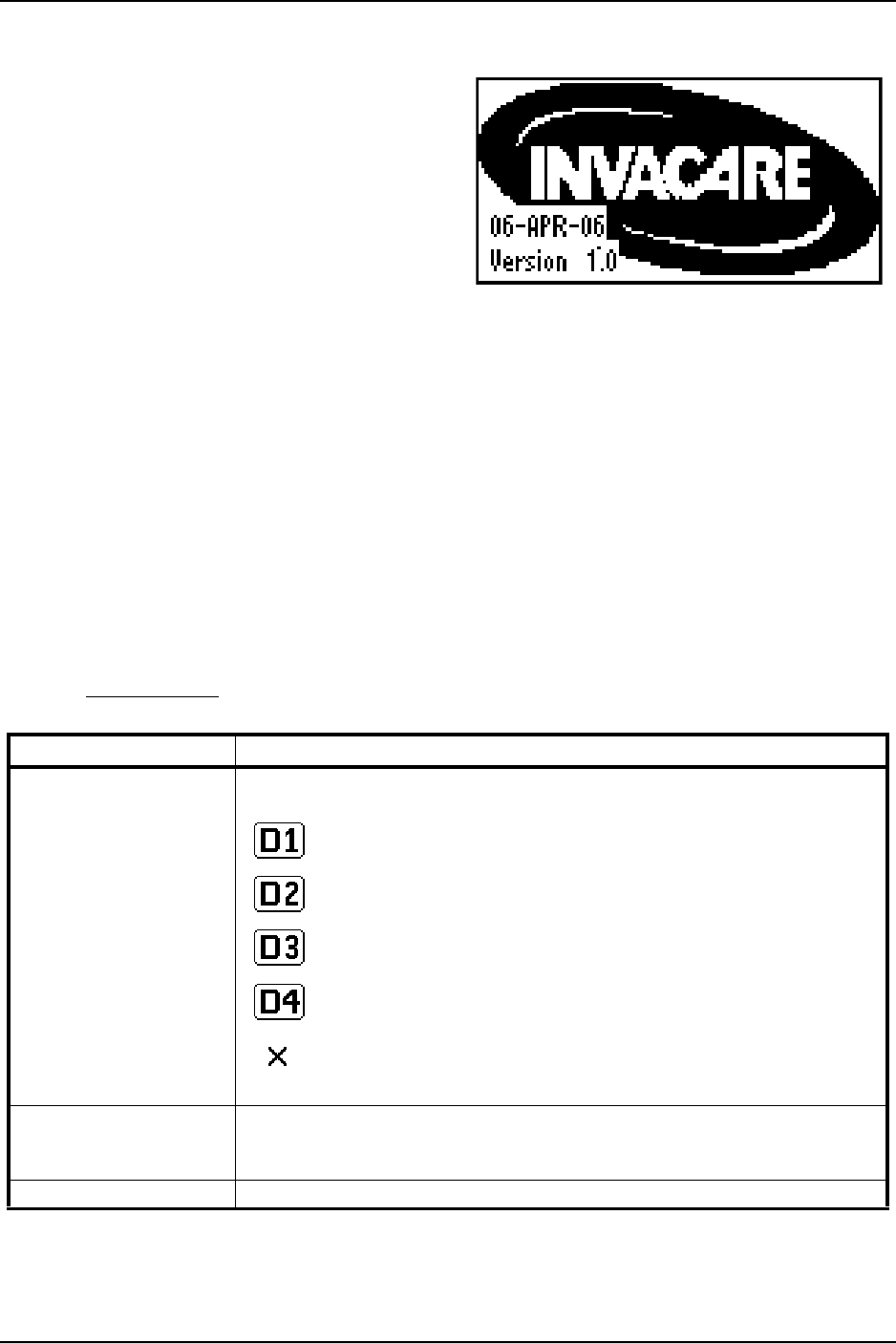
SECTION 5—WHEELCHAIR OPERATION
Part No 1143190 41 TDX™ SP
Splash Screen
NOTE:Forthisprocedure,referto
FIGURE 5.5.
Thisscreenisdisplayedatstartupofthe
joystickforabout2seconds.Thisscreen
displaysthesoftwareversionanddate
information.
Afterthisscreen,thejoystickdisplaysthe
MainScreen.
FIGURE 5.5 LCD Display Screens - Splash
Screen
Main Screen
NOTE:Forthisinformation,refertoFIGURE 5.6onpage 42.
Duringnormaloperation,theactivedriveisdisplayedintheupperhalfoftheLCD
display.BatterychargelevelisshownintheBatteryGaugeDisplay(BGD)locatedonthe
rightsideoftheLCDdisplay.Atfullcharge,solidblocksfillinalltensegmentsbetween
E(Empty)andF(Full).Asthebatterybecomesdischarged,thetopmostsegmentswill
progressivelydisappearuntilnosegmentsappearbetweenEandF.Atthislevel,theuser
shouldchargethebatteriesassoonaspossible.
ThelowerhalfoftheLCDdisplayistheInformationCenter.TheInformationCenter
displayscurrentdataonthewheelchair.
RefertoLCDDisplaytableonpage 41fordescriptionsofinformationshown.
LCD DISPLAY
ITEM DESCRIPTION
DRIVE NAME This field shows the currently selected Drive’s Name.
Available choices are as follows:
Drive 1*
Drive 2*
Drive 3*
Drive 4*
“No Drive” selected via the programmer.
*NOTE: Drive names can be customized. Actual drive names may display differently.
BATTERY LEVEL
INDICATOR
This symbol shows the Battery Level and will change depending on the available
battery power.
This indicator is shown on every screen.
STATUS MESSAGE This area displays status or instructions.

SECTION 5—WHEELCHAIR OPERATION
TDX™ SP 42 Part No 1143190
FIGURE 5.6 LCD Display Screens - Main Screen
Driving Screen
NOTE:Forthisprocedure,referto
FIGURE 5.7.
Thisscreenisshownwhentheoperator
issuesadrivecommandandtheDriveIcon
onthemainscreenwashighlighted.
NOTE:TheDrive’sname,warning/info
message,statusiconandbatteryindicatorare
displayedonthisscreen. FIGURE 5.7 LCD Display Screens - Driving
Screen
STATUS INDICATOR The status indicator will show a “Warning” (exclamation point inside a triangle)
indicator when the chair has a condition that requires attention.
The status indicator will show a “STOP” sign when a serious condition exists. The
chair will not be allowed to operate.
The status indicator shows an Attendant Icon if the attendant’s override switch is
active.
MODES The dotted-box shows the area that contains the available “modes” in the cur-
rently selected drive. The modes are programmed for each drive and are based
upon the configuration of the chair.
These modes are highlighted when the Mode is active. The operator changes
modes by pressing the Mode Select Switch.
The available modes are as follows:
Drive Mode (1 through 4)
Automatic Positioning
Actuator Control Switch Mode (4-switch, 4-switch 2 levels, etc.)
ECU Output Activated (1 through 4)
RIM Mode Activated
Drive Select Mode Activated
No Driving
ITEM DESCRIPTION
Available Modes in
this Drive (Must be
Programmed)
ECU
Drive Indicator
Icon appears when a
joystick command will
drive the wheelchair
Battery Gauge Display
Status/Info Message Area Status Indicator
Drive Profile Name
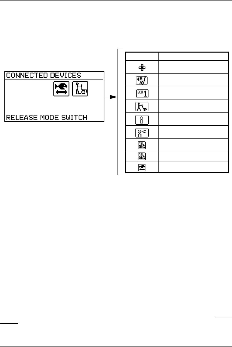
SECTION 5—WHEELCHAIR OPERATION
Part No 1143190 43 TDX™ SP
Connected Devices Screen
NOTE:Forthisprocedure,refertoFIGURE 5.8.
ThisscreenisdisplayediftheModeSelectswitchisheldactiveforabout10seconds.This
screenshowsaniconthatrepresentsanyadditionaldevicesthatareconnectedtothe
chair.
FIGURE 5.8 LCD Display Screens - Connected Devices Screen
Programmable Mono Port 1/2 or External Mode Switch
Theprogrammablemonoportorexternalmodeswitchinputislocatedattherearofthe
joystickontheleftside.Theprogrammablemonoportinputoffersthechoiceofthree
options:
•Remotedriveselect
•Remotestop/mode(reset)input
•Singleactuatorinput
Thesingleswitchfunctionsoperatethroughmonoport1.Anoptionaly‐cableallowsa
secondprogrammablefunctionthroughmonoport2.
Remote Stop Switch
Theremotestopswitchisusedtostopthewheelchair.
Remote Mode (Reset) Switch
Theremotemoderesetswitchfunctionsthesamewayasthemodeswitch.RefertoMode
Switchonpage 44.
ICON DESCRIPTION
4-Switch Attendant Control
RIM Control
ECU (1 to 4)
Proportional Attendant Control
Compact Joystick
Sip and Puff Control
ASL Digital Control
ASL Analog Control
Shark Power Module Actuator

SECTION 5—WHEELCHAIR OPERATION
TDX™ SP 44 Part No 1143190
Remote On/Off Switch
TheremoteOn/Offswitchinputislocatedattherearofthejoystickontherightsideand
allowsthepowerswitchtobeoperatedbyanabilityswitch(normallyopenmomentary
switchwithmonoplug).TousetheremoteOn/Offfeature,theDriveSelect/On/Offswitch
mustbeintheOnposition.Eachactivationoftheabilityswitchwillalternatelyturnthe
joystickOnorOff.
Mode Switch
NOTE:Forthisprocedure,refertoFIGURE 5.4onpage 40.
Themodeswitchisusedtoselecttheoperatingmodeforthewheelchair.Themode
switchislocatedonthejoystick.Amodeswitchisneededwheneveranyofthefollowing
operatingmodesareprogrammed:
• EnvironmentalControls(ECU1,ECU2,ECU3,ECU4)*
•3SpeedModeinDigital3Speed(Slow,Medium,Full)
•LatchedModes
•SleepMode
•RIMMode*
•RemoteDriveSelectionMode*
• Tilt/ReclineMode*
• InformationCenterDisplaySelection(doesnotrequireResetactivationatpowerup)
Ifanyoftheabovemodesareselected,thecontrolwillrequireactivationoftheswitch
immediatelyafterthepowerswitchisturnedOninordertoenterthedrivemode.The
secondlineoftheLCDwilldisplay‐PRESSRESET.
*NOTE:Inthesemodes,StandbySelectallowstheresetswitchtobebypassedforusersunableto
activatetheswitch.
Memory Card Slot
Thememorycardslotisusedwiththebasicorprofessionalmemorycardforsavingor
readingwheelchairparameters.
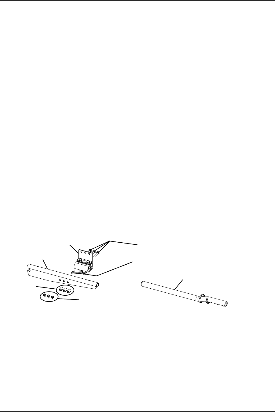
SECTION 5—WHEELCHAIR OPERATION
Part No 1143190 45 TDX™ SP
Repositioning Joystick
Van Seats
NOTE:Forthisprocedure,refertoFIGURE 5.9.
NOTE:Takenoteofpositionandorientationofmountinghardwareforreinstallingthejoystick
assembly.
1. Turntheadjustmentlocklevertoreleasethejoystickmountingtubefromthe
mountingbracket.
2. Removethejoystickmountingtubefromthewheelchair.
3. Removethethreehexmountingscrews,bushingsandlocknutsthatsecurethe
mountingbrackettothethreemountingholesonthearmrestplate.
NOTE:Themountingbracketismountedtotheinsideofthearmrestplate.
4. Repositionthemountingbracketontheoppositearmrestplate.
5. Usingthethreehexmountingscrews,bushingsandlocknutssecurethemounting
brackettothethreemountingholesofthearmrestplate.
6. Ifnecessary,performthefollowingtorepositiontheadjustmentlock:
A. Slidetheadjustmentlockfromthemountingbracket.
B. Rotateadjustmentlock180°andslideadjustmentlockovertheoppositeendofthe
mountingbracket.
7. Slidejoystickmountingtubethroughthemountingbrackettothedesiredposition
andsecureadjustmentlocktotubebyturningleveronadjustmentlock.
FIGURE 5.9 Repositioning Joystick - Van Seats
Locknuts
Bushings
Armrest Plate
Mounting Bracket Hex Mounting Screws
Adjustment Lock Lever
Joystick Mounting Tube
NOTE:Joystick
notshown.
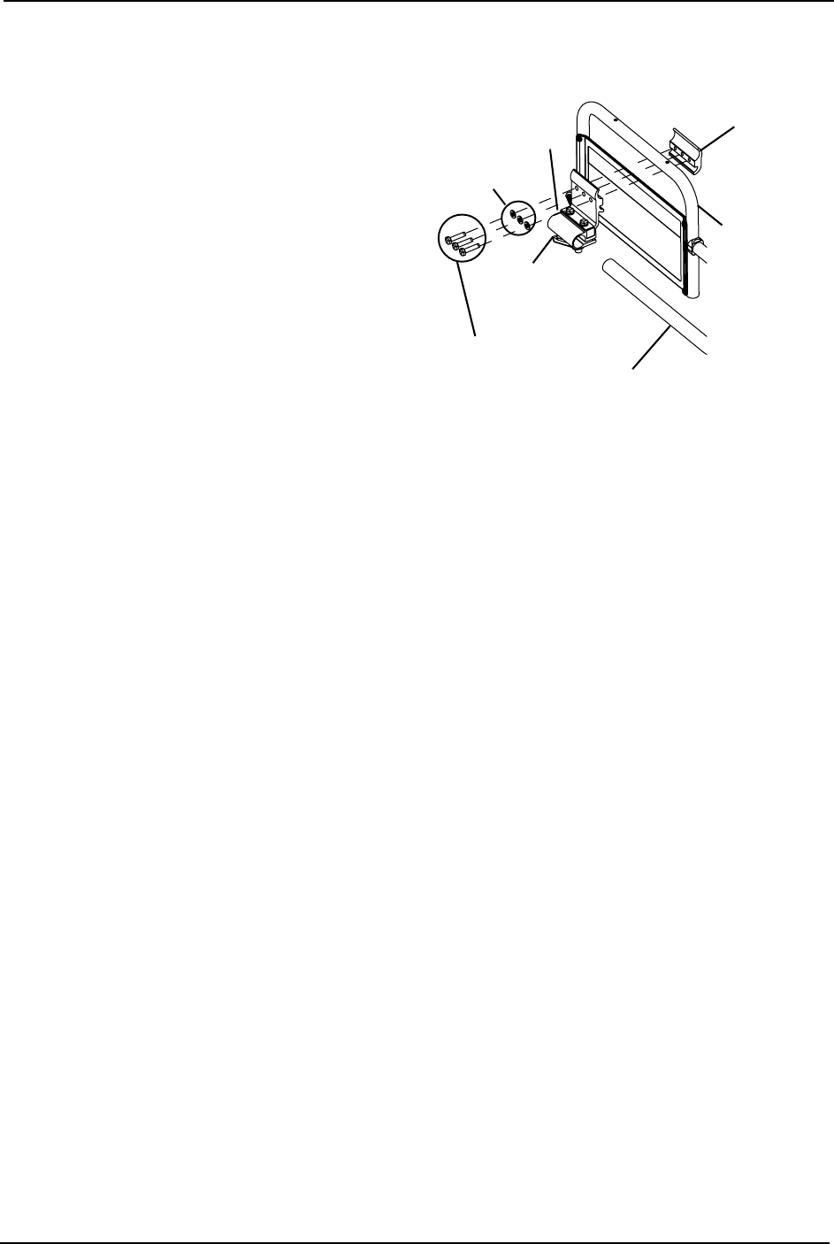
SECTION 5—WHEELCHAIR OPERATION
TDX™ SP 46 Part No 1143190
Adjustable ASBA Seats
NOTE:Forthisprocedure,referto
FIGURE 5.10.
1. Turntheadjustmentlockleverto
releasethejoystickmountingtubefrom
themountingbracket.
2. Removethejoystickfromthewheelchair.
3. Removethethreehexscrewsthat
securebothhalvesofthemounting
brackettothearmtube.
4. Repositionmountingbracketon
oppositearmtubeensuringthe
threadedplateofthemountingbracket
isontheinsideofthearmtubeas
showninFIGURE 5.10.
FIGURE 5.10 Repositioning Joystick -
Adjustable ASBA Seats
5. Usingthethreehexmountingscrewsandwashers,securebothhalvesofthemounting
brackettothearmtube.
6. Slidethejoystickmountingtubethroughthemountingbrackettothedesiredposition.
7. Turntheadjustmentlocklevertosecurethejoystickmountingtubeintothemounting
bracket.
Disconnecting/Connecting the Joysticks
NOTE:Forthisprocedure,refertoFIGURE 5.11onpage 47.
NOTE:Thejoystickconnectorislocatedattherearoftheseatframe.
SPJ+ Joysticks
Disconnecting
1. Loosenthethumbscrewsonthejoystickconnector.
2. Disconnectthejoystickconnectorfromthecontrollerconnector.
Connecting
1. Alignthejoystickconnectorwiththecontrollerconnector.
2. Securethejoystickconnectortothecontrollerconnectorusingthethumbscrewson
thecontrollerconnector.
Washers
Hex Mounting
Screws
Mounting
Bracket
Adjustment
Lock Lever
Joystick Mounting Tube
Mounting Bracket
(Threaded Plate)
Arm Tube
NOTE:
Joystick
notshown.
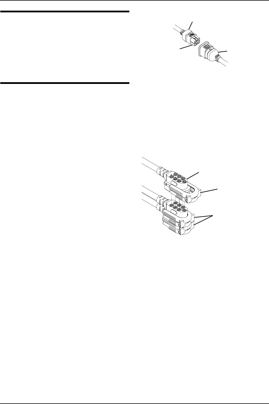
SECTION 5—WHEELCHAIR OPERATION
Part No 1143190 47 TDX™ SP
WARNING
The excess joystick cable must be
coiled, and tie-wrapped to the rear of
the seat frame to ensure that cable does
NOT become entangled or damaged
during normal operation of seating sys-
tem - otherwise injury or damage may
result.
3. Ifnecessary,coilandtiewrapexcess
joystickcabletorearofseatframe.
FIGURE 5.11 Disconnecting/Connecting
the Joysticks - SPJ+ Joysticks
MPJ+ Joysticks
NOTE:Forthisprocedure,refertoFIGURE 5.12.
Disconnecting
1. Pullthelatchawayfromthejoystick
connector.
2. Disconnectthejoystickconnectorfrom
theremainingconnectors.
Connecting
1. Ensurethelatchispulledawayfrom
thejoystickconnector.
2. Connectthejoystickconnectortothe
otherconnectors.
3. Pushthelatchintosecurethejoystick
connectortotheotherconnectors.
FIGURE 5.12 Disconnecting/Connecting
the Joysticks - MPJ+ Joysticks
Joystick
Connector
Light Grey Collar
Controller
Connector
Joystick
Connector
Latch
Other Connectors
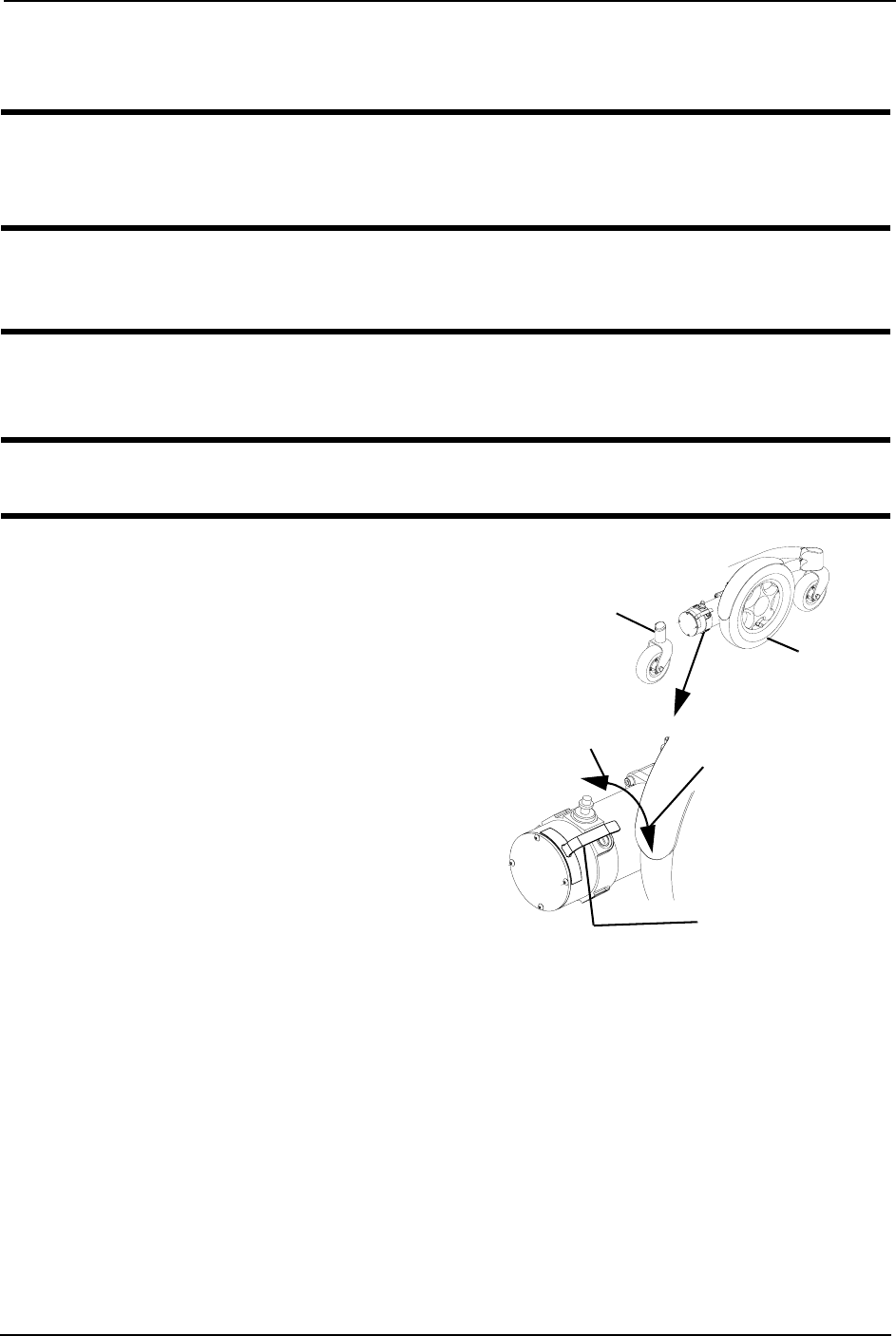
SECTION 6—MOTOR LOCKS
TDX™ SP 48 Part No 1143190
SECTION 6—MOTOR LOCKS
WARNING
After ANY adjustments, repair or service and before use, make sure that all
attaching hardware is tightened securely - otherwise injury or damage may result.
CAUTION
As with any vehicle, the wheels and tires should be checked periodically for cracks
and wear, and should be replaced.
Disengaging/Engaging Motor Lock Levers
WARNING
DO NOT engage or disengage motor locks until the power is in the OFF position.
NOTE:Forthisprocedure,referto
FIGURE 6.1.
NOTE:Motorlockdisengagement/
engagementallowsfree‐wheelingorjoystick
controlledoperation.Free‐wheelingallowsan
assistanttomaneuverthewheelchairwithout
power.
NOTE:Motorlockleversarelocatedbetween
therearcasterassemblyanddrivewheelon
bothsidesofthewheelchair.
1. Performoneofthefollowing
(FIGURE 6.1):
• Disengage(PUSH)‐Pushmotor
lockleversdown.
• Engage(DRIVE)‐Pullmotorlock
leversup.
FIGURE 6.1 Disengaging/Engaging Motor
Lock Levers
Motor Lock Lever
ENGAGE (Drive) Motor Lock Lever
DISENGAGE (Push)
Outside of
Wheelchair
Motor Lock Lever
Rear Caster
Assembly
Drive
Wheel
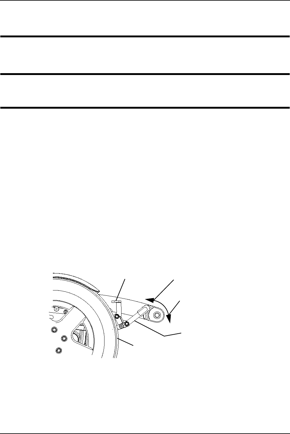
SECTION 7—WHEEL LOCKS
Part No 1143190 49 TDX™ SP
SECTION 7—WHEEL LOCKS
WARNING
After ANY adjustments, repair or service and before use, make sure that all
attaching hardware is tightened securely - otherwise injury or damage may result.
CAUTION
DO NOT use the wheel locks when the wheelchair power is on and the clutches are
engaged - otherwise damage to the wheelchair may result.
NOTE:Usethewheellockswhenevertheclutchesaredisengagedandthewheelchairisbeing
pushed.
Disengaging/Engaging the Wheel locks
NOTE:Forthisprocedure,refertoFIGURE 7.1.
Engaging
1. Pushhandleforwardawayfromtiretoengagewheellock.
2. RepeatSTEP1foroppositewheel.
Disengaging
1. Pullhandlebacktowardtiretodisengagewheellock.
2. RepeatSTEP1foroppositewheel.
FIGURE 7.1 Disengaging/Engaging the Wheel locks
ENGAGE
Wheel Lock Handle
Wheel Lock
Drive Wheel
DISENGAGE

SECTION 8—FOOTBOARD ASSEMBLY
TDX™ SP 50 Part No 1143190
SECTION 8—FOOTBOARD
ASSEMBLY
WARNING
After ANY adjustments, repair or service and before use, make sure that all
attaching hardware is tightened securely - otherwise injury or damage may result.
Before performing any maintenance, adjustment or service, verify that ON/OFF
switch on the joystick is in the OFF position.
DO NOT stand on the flip-up footboard. When getting in or out of the wheelchair,
make sure that the flip-up footboard is in the upward position.
LIMITED CLEARANCE BETWEEN FOOTBOARD AND CASTER - The user’s feet
MUST remain on the footboard while operating the wheelchair. If the user’s feet
are allowed to rest off the side of the footboard they may come in contact with the
caster possibly resulting in injury.
Removing/Installing the Footboard
NOTE:Forthisprocedure,refertoFIGURE 8.1onpage51.
Removing
1. Removethesocketheatscrew,threewashers,spacerandlocknutthatsecuresthe
footboardtothefootboardsupport.
2. Removethefootboardfromthefootboardsupport.
Installing
WARNING
Pinch point may occur when rotating the footboard assembly.
1. Positionthefootboardontothefootboardsupportsothatthemountingholesinthe
wheelchairframealignwiththedesiredmountingholesinthefootboardsupport.
2. Usingthesocketheatscrew,threewashers,spacerandlocknutsecurethefootboard
tothefootboardsupport.
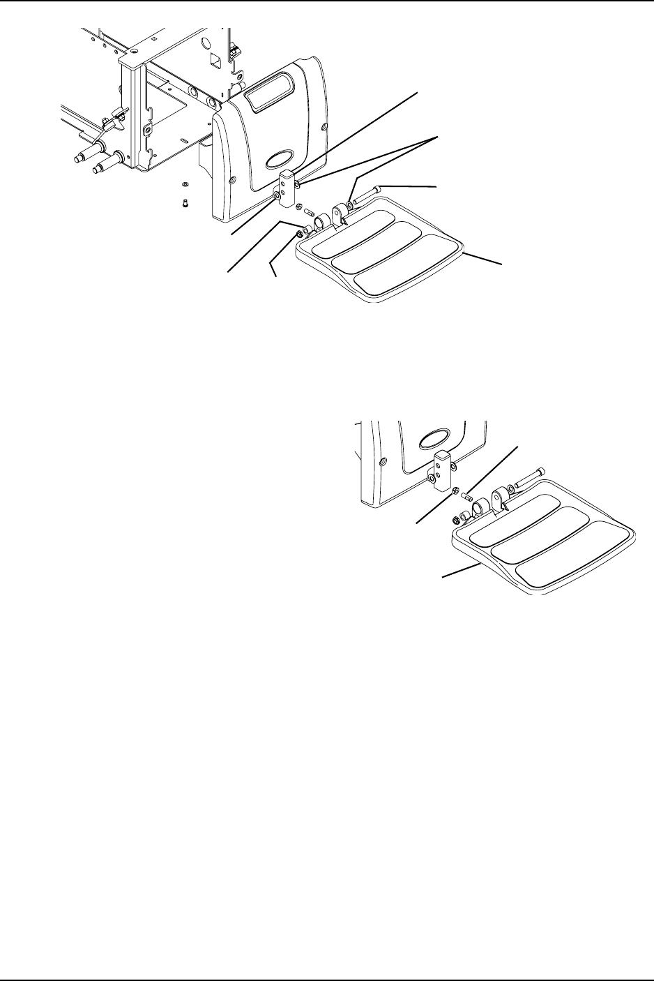
SECTION 8—FOOTBOARD ASSEMBLY
Part No 1143190 51 TDX™ SP
FIGURE 8.1 Removing/Installing the Footboard
Adjusting the Footboard Angle
NOTE:Forthisprocedure,refertoFIGURE 8.2.
1. Loosenthejamnutandsetscrew
locatedunderneathontherearofthe
footplate.
2. Adjustthemountingscrewinoroutto
obtainthedesiredfootboardangle.
3. Threadthejamnutinwarduntilitis
flushwiththefootboardbracket.
4. Securelytightenthejamnutandwasher
tosecurethemountingscrewinplace. FIGURE 8.2 Adjusting the Footboard Angle
Footboard
Assembly
Locknut
Spacer
Washers
Socket Head
Screw
Washer
Footboard Support
Set Screw
Footboard
Jam Nut
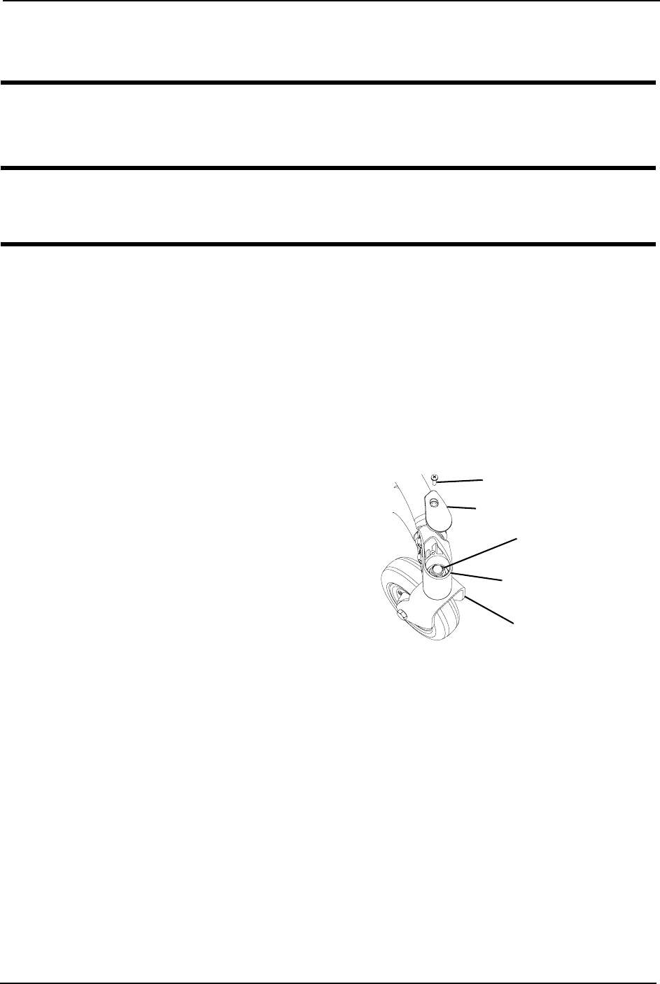
SECTION 9—FORKS
TDX™ SP 52 Part No 1143190
SECTION 9—FORKS
WARNING
After ANY adjustments, repair or service and before use, make sure that all
attaching hardware is tightened securely - otherwise injury or damage may result.
CAUTION
As with any vehicle, the wheels and tires should be checked periodically for cracks
and wear, and should be replaced.
Adjusting Forks
NOTE:Forthisprocedure,refertoFIGURE 9.1.
1. Removetheretainingscrewthatsecurestheheadtubecoverinplace.
2. Removetheheadtubecover(notshown)fromthecasterheadtube.
3. Toproperlytightencasterjournalsystemandguardagainstflutter,performthe
followingcheck:
A. Tipbackthewheelchairtofloor.
B. Pivotbothforksandcasterstotop
oftheirarcsimultaneously.
C. Letcastersdroptobottomofarc
(wheelsshouldswingoncetoone‐
side,thenimmediatelyrestina
straightdownwardposition).
D. Adjustlocknutsaccordingto
freedomofcasterswing. FIGURE 9.1 Adjusting Forks
4. Testwheelchairformaneuverability.
5. Readjustlocknutsifnecessary,andrepeatSTEPS1‐3untilcorrect.
6. Snapheadtubecoverintothecasterheadtube.
7. Reinstallretainingscrews.
Locknut
Fork
Retaining Screw
Caster Headtube
Headtube Cover

SECTION 10—BATTERIES
Part No 1143190 53 TDX™ SP
SECTION 10—BATTERIES
WARNING
The use of rubber gloves is recommended when working with batteries.
Invacare strongly recommends that battery installation and battery replacement
always be done by a qualified technician.
After ANY adjustments, repair or service and before use, make sure all attaching
hardware is tightened securely - otherwise injury or damage may result.
22NF batteries weigh 37 pounds each. Use proper lifting techniques (lift with your
legs) to avoid injury.
ALWAYS use a battery lifting strap when lifting a battery. It is the most convenient
method and assures that the battery acid will not spill. It also helps to prolong the
life of the battery.
DO NOT tip the batteries. Keep the batteries in an upright position.
NEVER allow any of your tools and/or battery cable(s) to contact BOTH battery
post(s) at the same time. An electrical short may occur and serious personal injury
or damage may occur.
When tightening the clamps, always use a box wrench. Pliers will “round off” the
nuts. NEVER wiggle the battery terminal(s)/post(s) when tightening. The battery
may become damaged.
The POSITIVE (+) RED battery cable MUST connect to the POSITIVE (+) battery
terminal(s)/post(s), otherwise serious damage will occur to the electrical system.
Install protective caps on POSITIVE (+) and NEGATIVE (-) battery terminals.
DO NOT remove fuse or mounting hardware from POSITIVE (+) RED battery
cable mounting screw.
Unless otherwise indicated, make sure power to the wheelchair is OFF before
performing these procedures.
After ANY adjustments, repair or service and before use, make sure all attaching
hardware is tightened securely - otherwise injury or damage may occur.
NOTE:Ifthereisbatteryacidinthebottomofthebatterytrayoronthesidesofthebattery(ies),
applybakingsodatotheseareastoneutralizethebatteryacid.Beforereinstallingtheexistingor
newbattery(ies),cleanthebakingsodafromthebatterytrayorbattery(ies)beingsuretoavoid
contactwithskinandeyes.Determinesourceofcontamination.NEVERinstall/reinstallabattery
withacrackedorotherwisedamagedcase.
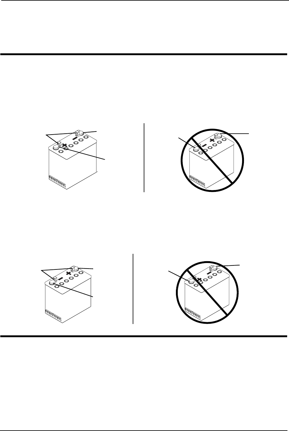
SECTION 10—BATTERIES
TDX™ SP 54 Part No 1143190
Using the Proper Batteries
1. Positionbatteryonground/flatsurfaceasshownbelow.
2. Visuallyinspectthebatterytoensureproperpolarity:
WARNING
FOR TDX SP WHEELCHAIRS USING 22NF BATTERIES
Batteries with terminal configuration (POSITIVE on the left and NEGATIVE on the
right) as shown below MUST be used. Batteries that have the reverse terminal
configuration MUST not be used - otherwise injury and damage may occur.
Terminals MUST have a cross hole in them as shown below.
.
FOR TDX SP WHEELCHAIRS USING GP24 BATTERIES
Batteries with terminal configuration (POSITIVE on the right and NEGATIVE on
the left) as shown below MUST be used. Batteries that have the reverse terminal
configuration MUST not be used - otherwise injury and damage may occur.
Terminals MUST have a cross hole in them as shown below.
PROPER BATTERIES TO USE DO NOT USE THIS TYPE OF BATTERY
POSITIVE
(+) Battery
Terminal/
Post
NEGATIVE (-)
Battery
Terminal/Post
POSITIVE
(+) Battery
Terminal/
Post
NEGATIVE
(-) Battery
Terminal/
Post
Terminal Cross
Hole
POSITIVE
(+) Battery
Terminal/
Post
NEGATIVE
(+) Battery
Terminal/Post
POSITIVE (+)
Battery
Terminal/Post
NEGATIVE
(+) Battery
Terminal/Post
PROPER BATTERIES TO USE DO NOT USE THIS TYPE BATTERY
Terminal
Cross
Hole

SECTION 10—BATTERIES
Part No 1143190 55 TDX™ SP
Replacing Batteries
NOTE:Forthisprocedure,refertoFIGURE 10.1onpage 56.
NOTE:Thefollowingtoolsarerequiredtoperformthisprocedure:
•WireCutter
1. Removethebatteriesfromthewheelchair.RefertoRemoving/InstallingtheBatteries
From/IntotheWheelchaironpage 57.
2. Cutthetie‐wrapsthatsecurethebatteryterminalcoverstothebatteryterminals.
3. SlidetheREDbatteryterminalcoverbackontheREDbatterycabletoexposethe
POSITIVEbatteryterminal.
4. SlidetheBLACKbatteryterminalcoverbackontheBLACKbatterycabletoexpose
NEGATIVEbatteryterminal.
WARNING
NEVER allow any of your tools and/or battery cable(s) to contact BOTH battery
post(s) at the same time. An electrical short may occur and serious personal injury
or damage may occur.
5. RemovethelocknutthatsecuresthebracketofthePOSITIVEbatterycabletothe
POSITIVE(+)batterypostofthebattery.
6. RemovethelocknutthatsecurestheNEGATIVEbatterycabletotheNEGATIVE(‐)
batterypostofthebattery
7. Discardtheexistingbattery.
8. Positionbatteryconnectorbracketorwiringharnessontothenew22NForGP24
batteryasshown.
9. SecuretheNEGATIVEbatterycabletotheNEGATIVE(‐)batterypostwithexisting
mountingscrewandlocknut.
10. SecurethebracketofthePOSITIVEbatterycabletothePOSITIVE(+)batterypostwith
existingmountingscrewandlocknut.
11. Positioneachbatteryterminalcoverovertopofeachbatteryterminal.
12. Securebatteryterminalcoversinplacewithonetie‐wrap.
13. Installbatteriesintowheelchair.RefertoRemoving/InstallingtheBatteriesFrom/Into
theWheelchaironpage 57.
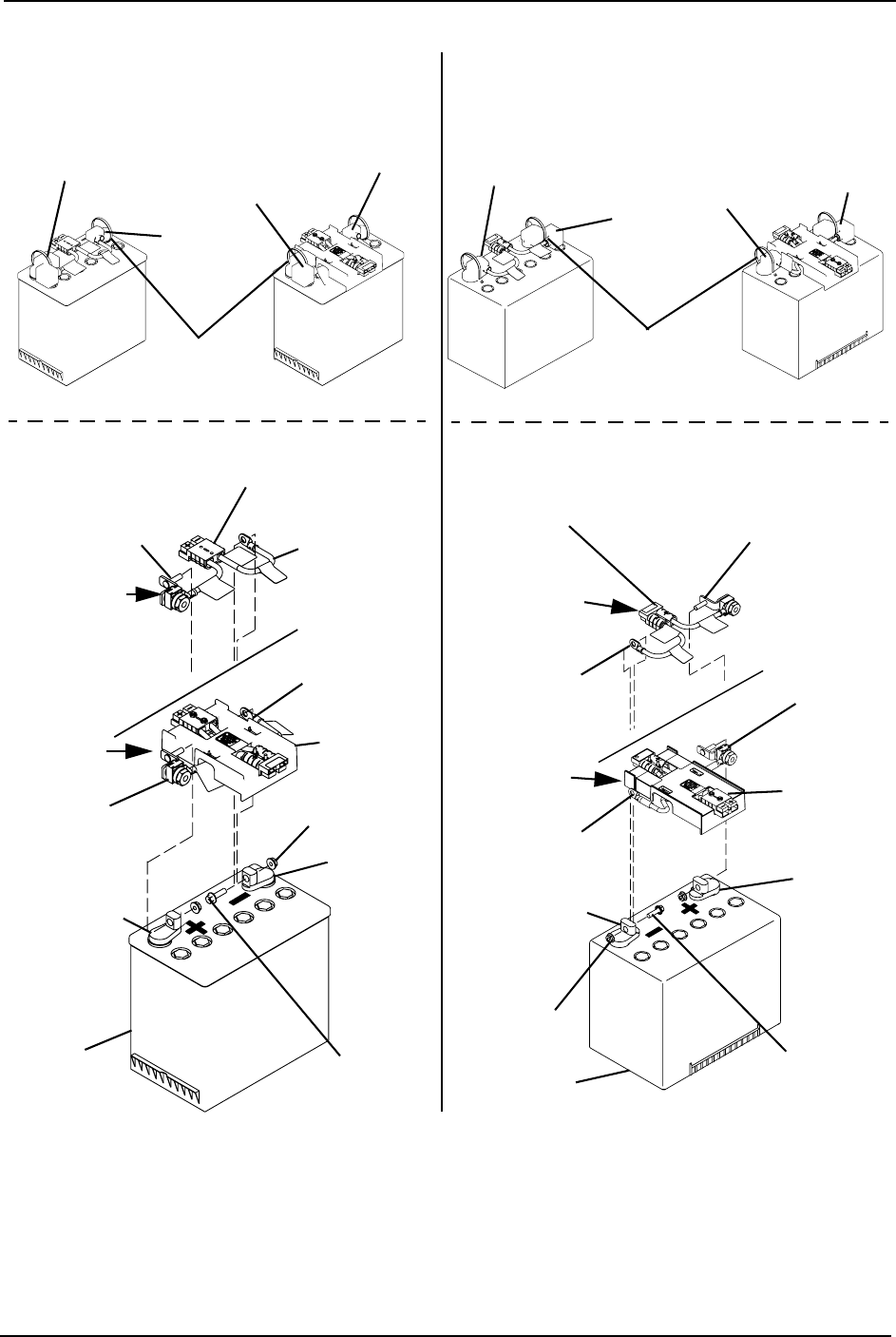
SECTION 10—BATTERIES
TDX™ SP 56 Part No 1143190
N
FIGURE 10.1 Replacing Batteries
Bracket of
POSITIVE Battery
Cable
Battery
Connector
Bracket
POSITIVE
(+) Battery
Terminal
/Post
Mounting
Screw
GP24 Battery
NEGATIVE (-)
Battery Cable
NEGATIVE (-)
Battery
Terminal/Post
Locknut
BLACK Battery
Terminal Cover RED Battery
Terminal Cover
Tie-Wrap
Battery Wiring
Harness
FOR FRONT
BATTERY
FOR REAR
BATTERY
Bracket of
POSITIVE (+)
Battery
Cable
NEGATIVE (-)
Battery Cable
BATTERY COVER AND
TIE-WRAP DETAIL
RED
Cover
BLACK
Cover
GP24 Batteries22NF Batteries
Bracket of
POSITIVE
Battery Cable
Battery
Connector
Bracket
POSITIVE (+)
Battery
Terminal
/Post
Mounting
Screw
22NF
Battery
NEGATIVE (-)
Battery Cable
NEGATIVE
(-) Battery
Terminal/
Post
Locknut
Battery Wiring Harness
FOR FRONT
BATTERY
FOR REAR
BATTERY
Bracket of
POSITIVE
Battery Cable
NEGATIVE (-)
Battery Cable
BLACK Battery
Terminal Cover
RED Battery
Terminal Cover
Tie-Wrap
BATTERY COVER AND
TIE-WRAP DETAIL
BLACK
Cover
RED
Cover

SECTION 10—BATTERIES
Part No 1143190 57 TDX™ SP
Cleaning Battery Terminals
WARNING
Most batteries are not sold with instructions. However, warnings are frequently
noted on the cell caps. Read them carefully.
DO NOT allow the liquid in the battery to come in contact with skin, clothes or
other possessions. It is a form of acid and harmful or damaging burns may result.
Should the liquid touch your skin, wash the area IMMEDIATELY and thoroughly
with cool water. In serious cases or if eye contact is made, seek medical attention
IMMEDIATELY.
1. Examinebatteryterminalsforcorrosion.
2. Verifytheplasticcapsareinplaceoverbatterycellholes.
3. Cleanterminalsbyusingabatterycleaningtool,wirebrush,ormediumgradesand
paper.
NOTE:Uponcompletion,areasshouldbeshiny,notdull.
4. Carefullydustoffallmetalparticles.
Removing/Installing the Batteries From/Into the
Wheelchair
Removing the Front Shroud/Battery Retention Bracket and Rear
Shroud
CAUTION
Place the wheelchair in a well ventilated area where work can be performed
without risking damage to carpeting or floor covering.
NOTE:Forthisprocedure,refertoFIGURE 10.2onpage 58.
1. VerifythejoystickOn/OffswitchisintheOffposition.
2. Removethethreemountingscrewsthatsecuretherearshroudtothewheelchair.
3. Removetherearshroudfromthewheelchair.
NOTE:Thefrontshroudandbatteryretentionbracketareremovedfromandinstalledontothe
wheelchairframeasasingleunit.
4. Removethetwomountingscrewssecuringthefrontshroud/batteryretentionbracket
tothewheelchair.
5. WheelchairswithFootboardsOnly:Removethemountingscrewandwashersecuring
thefootboardsupporttothewheelchairframe.
6. Liftuptounhookthebatteryretentionbracketfromthewheelchairframeandremove
thefrontshroud/batteryretentionbracketfromthewheelchair.
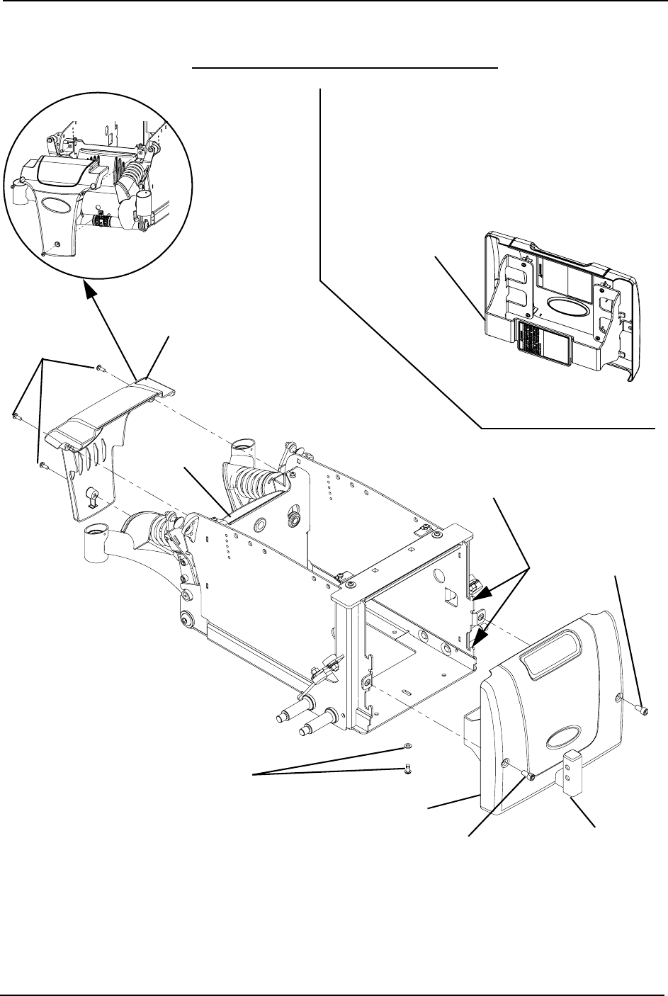
SECTION 10—BATTERIES
TDX™ SP 58 Part No 1143190
7. Disconnectthecontrollerfromthebatteriesattherearofthewheelchair.
8. Removethebatteries.RemovingtheBatteriesfromWheelchaironpage 59.
FIGURE 10.2 Removing the Front Shroud/Battery Retention Bracket and Rear Shroud -
Installing the Front Shroud/Battery Retention Bracket and Rear Shroud
Front Shroud
Controller
Mounting
Screws
Rear Shroud
Mounting
Screw
Wheelchair Frame
(Battery Retention Bracket Hooks
to Wheelchair Frame Here)
DETAIL “A” -
FRONT SHROUD
Battery Retention
Bracket
Mounting
Screw
Footboard Support
(Wheelchairs with
Footboards Only
Mounting Screw
and Washer
(Wheelchairs with
Footboard Only)
NOTE:Batteryretentionbracketfor
two22nfbatteriesshown.
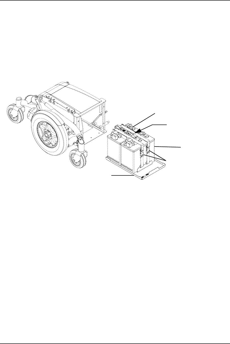
SECTION 10—BATTERIES
Part No 1143190 59 TDX™ SP
Removing the Batteries from Wheelchair
NOTE:Forthisprocedure,refertoFIGURE 10.3onpage 59.
1. Slidebatterytraywithbatteriesout.
2. Disconnectthebatterystraps.
3. Unplugfrontbatteryfromrearbattery.
4. Removethefrontbattery.
5. Slidetherearbatteryforwardandremoveitfromthetray.
FIGURE 10.3 Removing the Batteries from Wheelchair
Installing Batteries into Wheelchair
NOTE:Forthisprocedure,refertoFIGURE 10.3andFIGURE 10.4onpage 60.
NOTE:Positioningofthebatteriesintothebatterytrayiscompletedwithbatterytraypositioned
inwheelchairandpartiallypulledout.RefertoFIGURE 10.3forfullviewofwheelchairbase.
IllustrationsinFIGURE 10.4onpage 60areshownwithoutthewheelchairforclarification
purposesonly.
1. Positionthebatterywithbatteryconnectorbracketintherearofthebatterytrayinthe
orientationasshown.SeeDetail“A ” ofFIGURE 10.4onpage 60.
NOTE:Frontofbatterytrayisdesignatedbythebatterystop.Rearofthebatterytrayisthe
oppositeend.
NOTE:Orientationofthebatteryiscriticalotherwisebatterieswillnotconnecttothecontroller
oreachother.
2. Positiontheremainingbatteryinthefrontofthebatterytrayintheorientationshown
sothatthewiringharnessescanbeconnectedtogether.SeeDetail“B”ofFIGURE 10.4
onpage 60.
3. Connectfrontbatterytorearbattery.SeeDetail“B”ofFIGURE 10.4onpage 60.
4. Connectbatterystraps.SeeDetail“C”ofFIGURE 10.4onpage 60.
Disconnect Front Battery
from Rear Battery Here
FRONT OF
WHEELCHAIR
Rear Battery
Front Battery
Battery Straps
NOTE:Batterytray
shownremovedfor
clarity. Battery Tray
NOTE:22NFBatteries
shown.
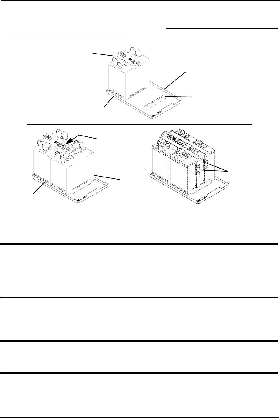
SECTION 10—BATTERIES
TDX™ SP 60 Part No 1143190
5. Slidethebatterytrayintothewheelchair(FIGURE 10.3).
6. Installthebatterydoorandrearshroud.RefertoInstallingtheFrontShroud/Battery
RetentionBracketandRearShroudonpage 60.
FIGURE 10.4 Installing Batteries into Wheelchair
Installing the Front Shroud/Battery Retention Bracket and Rear Shroud
WARNING
Wheelchairs with TRRO or TRBKTS Only - Battery retention brackets MUST be
installed at all times. Otherwise, the wheelchair will not be WC/19 compliant.
After installing front shroud, ensure that the mounting screws on the front shroud/
battery retention bracket are fully engaged into the battery box.
NOTE:Forthisprocedure,refertoFIGURE 10.2onpage 58.
1. Reinstallthefrontshroud/batteryretentionbracketontofrontofwheelchairframe.
2. Installtwomountingscrewsonthesidesofthefrontshroud/batteryretentionbracket.
WARNING
When installing batteries, ensure battery connector is securely engaged to the con-
troller connector - otherwise serious personal injury may result.
3. WheelchairswithFootboardsOnly:Usingthemountingscrewandwasher,securethe
footboardsupporttothewheelchairframe.
4. Connectthecontrollertothebatteriesattherearofthewheelchair.
DETAIL “A”
DETAIL “B” DETAIL “C”
Battery with Battery
Connector Bracket
Front of the Battery Tray
Rear of the Battery Tray
Battery Stop
Connect Front
Battery to
Rear Battery
HERE
Rear Battery
Front
Battery
Battery
Straps
NOTE:22NFBatteries
shown.
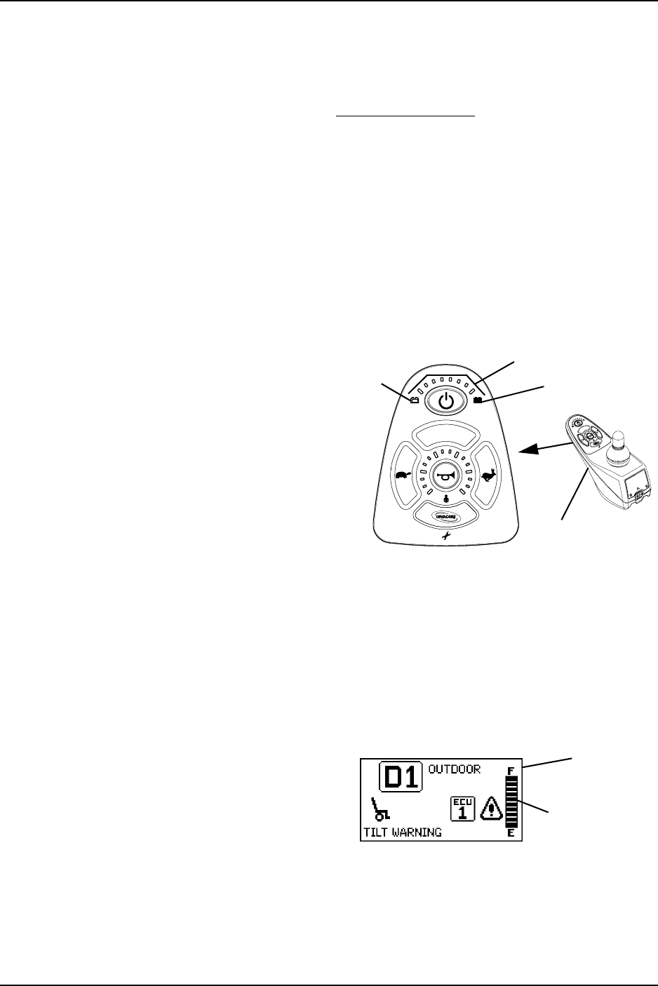
SECTION 10—BATTERIES
Part No 1143190 61 TDX™ SP
5. Reinstalltherearshroudandsecureinplacewiththreemountingscrews.
NOTE:NewBatteriesMUSTbefullychargedbeforeusing,otherwisethelifeofthebattery(ies)
willbereduced.
6. Ifnecessary,chargethebatteries.RefertoChargingBatteriesonpage 62.
When to Charge Batteries
SPJ+, SPJ+ w/PSS and SPJ+ w/ACC Joysticks
NOTE:Forthisprocedure,refertoFIGURE 10.5.
TheInformationGaugeDisplaylocatedonthefrontofthejoystickhousing,itprovides
thestate‐of‐batterycharge,includingnotificationofwhenthebatteryrequirescharging.
Italsoprovidesthefollowinginformationtotheuseronthestatusofthewheelchair:
A. GREENLEDsarelit,indicatingwell
chargedbatteries.
B. AMBERLEDsarelit,indicating
batteriesaremoderatelycharged.
Rechargebatteriesbeforetakinga
longtrip.
C. REDLEDsarelit,indicating
batteriesarerunningoutofcharge.
Rechargebatteriesassoonas
possible.
FIGURE 10.5 SPJ+, SPJ+ w/PSS and SPJ+ w/
ACC Joysticks
MPJ+ Joystick
NOTE:Forthisprocedure,refertoFIGURE 10.6onpage 61.
ThefarrightsideofthedisplayscreenistheBatteryGaugeDisplay(BGD).Itprovides
informationontheremainingchargeinthebatteries.
Atfullcharge,solidblocksfillinallten
segmentsbetweenE(Empty)andF(Full).
Asthebatterybecomesdischarged,the
segmentswillprogressivelydisappeara
baratatimeuntilnosegmentsappear
betweenEandF.Atthisleveltheuser
shouldchargethebatteriesassoonas
possible.
FIGURE 10.6 MPJ+ Joystick
Battery Charger/
Programming Port
Batteries Full
Batteries
Empty
Information Gauge Display
Battery Gage
Display
Display
Screen

SECTION 10—BATTERIES
TDX™ SP 62 Part No 1143190
Charging Batteries
WARNING
NEVER attempt to recharge the batteries by attaching cables directly to the
battery terminals or clamps. ALWAYS use the recharging plug located on the back
of the joystick.
DO NOT attempt to recharge the batteries and operate the power wheelchair at
the same time.
During use and charging, unsealed batteries will vent hydrogen gas which is
explosive in the right concentration with air.
CAUTION
Always charge new batteries before initial use or battery life will be reduced.
NOTE:Forthisprocedure,refertoFIGURE 10.7onpage 63.
NOTE:NewbatteriesMUSTbefullychargedpriortoinitialuseofthewheelchair.
NOTE:Asageneralrule,batteriesshouldberechargeddailytoassurethelongestpossiblelifeand
minimizetherequiredchargingtime.Plantorechargethebatterieswhenitisanticipatedthe
wheelchairwillnotbeusedforalongperiodoftime.
Therangeperbatterychargeusingrecommendedbatteriesshouldbeapproximately5to
9hoursoftypicaloperation.Extensiveuseoninclinesmaysubstantiallyreduceper
chargemileage.
Description and Use of Battery Chargers
Thechargerautomaticallyreducesthechargefromaninitiallyhighratetoazeroreading
atafullychargedcondition.Ifleftunattended,thechargershouldautomaticallyshut‐off
whenfullchargeisobtained.
Therearesomebasicconceptswhichwillhelpyouunderstandthisautomaticprocess.
Theyare:
Theamountofelectricalcurrentdrawnwithinagiventimetochargeabatteryiscalled
the“chargerate”.If,duetousage,thechargestoredinthebatteryislow,thechargerate
ishigh,asindicatedbytheGREENlightonthecharger.Initially,theGREENlightwill
stayilluminatedforashortperiodoftimefollowedbyalongerperiodofofftime.Asa
chargebuildsup,thechargerateisreduced,andtheGREENlightwillstayilluminated
foralongerperiodoftimefollowedbyashorterofftime.
WARNING
NEVER leave the charger unattended when the breaker has tripped. A fault condi-
tion exists. Unplug and discontinue using immediately. Contact an Invacare dealer.
NOTE:Ifperformingthechargingproceduresindependently,READandCAREFULLYfollowthe
individualinstructionsforeachcharger(suppliedorpurchased).
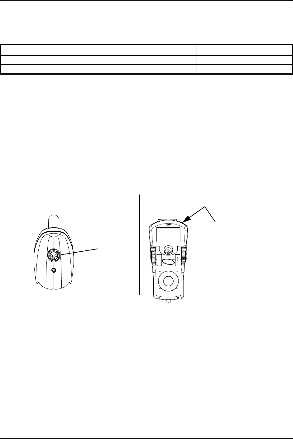
SECTION 10—BATTERIES
Part No 1143190 63 TDX™ SP
NOTE:Ifcharginginstructionsarenotsupplied,consultaqualifiedservicetechnicianforproper
procedures.
RequiredItems:
1. Attachthebatterychargerconnectortothechargerportonthejoystick.
2. Plugthecharger’sACpowercord,orextension,intothegrounded120VACwall
outlet.
3. Waituntilchargingiscomplete.
NOTE:Alloweighthoursfornormalcharging.Largerbatteries(greaterthan55ampere‐hours)or
severelydischargedbatteriesmayrequireuptosixteenhourstobeproperlychargedandequalized.
NOTE:Itisadvantageoustorechargefrequentlyratherthanonlywhennecessary.Infact,a
battery’slifeisextendedifthechargelevelismaintainedwellabovealowcondition.
NOTE:Ifthebatteriesneedtobechargedmoreoftenortakelongertochargethannormal,they
mayneedtobereplaced.ContactanInvacaredealerforservice.
FIGURE 10.7 Charging Batteries
TOOL QUANTITY COMMENTS
Battery Charger 1 Supplied
Extension Cord 1 Not Supplied
MPJ+ JoystickSPJ+, SPJ+ w/PSS and SPJ+ w/ACC
Joysticks
Charger/
Programming
Port
Charger/Programming Port
(On Front of Joystick)

SECTION 11—TRANSPORT READY PACKAGE (TRRO)
TDX™ SP 64 Part No 1143190
SECTION 11—TRANSPORT READY
PACKAGE (TRRO)
NOTE:Theinformationinthissectionisforwheelchairsorderedwiththetransportreadypackage
ONLY.
WARNING
Contact Invacare Corporation (800-333-6900) with any questions about using this
wheelchair for seating in a motor vehicle.
When feasible, wheelchair occupants should transfer into the vehicle seat and use
the OEM (Original Equipment Manufacturer) vehicle-installed restraint system.
This wheelchair has been dynamically tested in a forward-facing mode with the
specified crash test dummy restrained by BOTH pelvic and upper-torso belt(s)
(shoulder belts), and that BOTH pelvic and upper-torso belt(s) should be used to
reduce the possibility of head and chest impacts with vehicle components.
Use ONLY Wheelchair Tie-down and Occupant Restraint Systems (WTORS) which
meet the requirements of the SAE (Society of Automotive Engineers) J2249
Recommended Practice during travel in a motor vehicle.
This wheelchair has been tested for seating in a motor vehicle with the factory
installed wheelchair seating system ONLY.
This wheelchair MUST be in a forward facing position during travel in a motor
vehicle.
This wheelchair is equipped and has been dynamically tested to rely on
WHEELCHAIR-ANCHORED pelvic belts. If desired, VEHICLE-ANCHORED pelvic
belts may be used.
IT IS STRONGLY RECOMMENDED THAT BOTH PELVIC AND UPPER-TORSO
BELT(S) BE USED TO REDUCE THE RISK OF INJURY.
To reduce the potential of injury to vehicle occupants, wheelchair-mounted
accessories, including but not limited to IV poles, trays, respiratory equipment,
backpacks, and other personal items should be removed and secured separately.
Postural supports, positioning devices, and/or strap(s) should not be relied on for
occupant restraint. These items may be used IN ADDITION TO the wheelchair-
anchored or vehicle-anchored belts.
Seat angle is factory set at time of shipment. Adjustments to the wheelchair may
void WC 19 compliance. To maintain compliance, refer to wheelchair service
manual before making any adjustments.
DO NOT alter or substitute wheelchair frame parts, components, or seating
systems.
A sudden stop and/or collision may structurally damage your wheelchair.
Wheelchairs involved in such incidents should be replaced.
Spill proof batteries, such as “gel cells”, should be installed on wheelchairs to be
used during travel in a motor vehicle.

SECTION 11—TRANSPORT READY PACKAGE (TRRO)
Part No 1143190 65 TDX™ SP
WARNING
Transport ready packages are not retrofittable to existing models and are not field
serviceable.
Only use the transport brackets included with TRRO and TRBKTS for the purposes
described in this manual.
Battery retention brackets MUST be installed at all times. Otherwise, the wheel-
chair will not be WC/19 compliant. Refer to Removing/Installing the Batteries
From/Into the Wheelchair on page 57.
About Transport Ready Packages
TRROincludesfourfactory‐installedtransportbracketsandawheelchairanchored
pelvicbelt.TRROhasbeencrash‐testedinaccordancewithANSI/RESNAWCVol1
Section19FrontalImpactTestrequirementsforwheelchairswitha168lbcrashdummy,
whichcorrespondstoapersonwithaweightof114to209lbs.
TRBKTSincludesfourfactory‐installedwheelchairtransportbrackets.TRBKTShasnot
beencrash‐testedinaccordancewithWC19.Usethesetransportbracketsonlytosecure
anunoccupiedwheelchairduringtransport.
Asofthisdate,theDepartmentofTransportationhasnotapprovedanytie‐downsystems
fortransportationofauserwhileinawheelchair,inamovingvehicleofanytype.Itis
Invacare’spositionthatusersofwheelchairsshouldbetransferredintoappropriate
seatinginvehiclesfortransportationandusebemadeoftherestraintsmadeavailableby
theautoindustry.Invacarecannotanddoesnotrecommendanywheelchair
transportationsystems.
Compliance Information
ThiswheelchairconformswiththerequirementsoftheANSI/RESNAWC/Vol.1‐Section
19.
NOTE:ANSI=AmericanNationalStandardsInstitute,RESNA=RehabilitationEngineering
andAssistiveTechnologySocietyofNorthAmerica.
Thiswheelchairhasbeendynamicallytestedinaforward‐facingmodewiththespecified
crashtestdummy,whichcorrespondstoapersonwithaweightof114‐209pounds,
restrainedbyBOTHpelvicandupper‐torsobeltsinaccordancewithANSI/RESNAWC
Vol1Section19.BOTHpelvicandupper‐torsobeltsshouldbeusedtoreducethe
possibilityofheadandchestimpactswithvehiclecomponents.
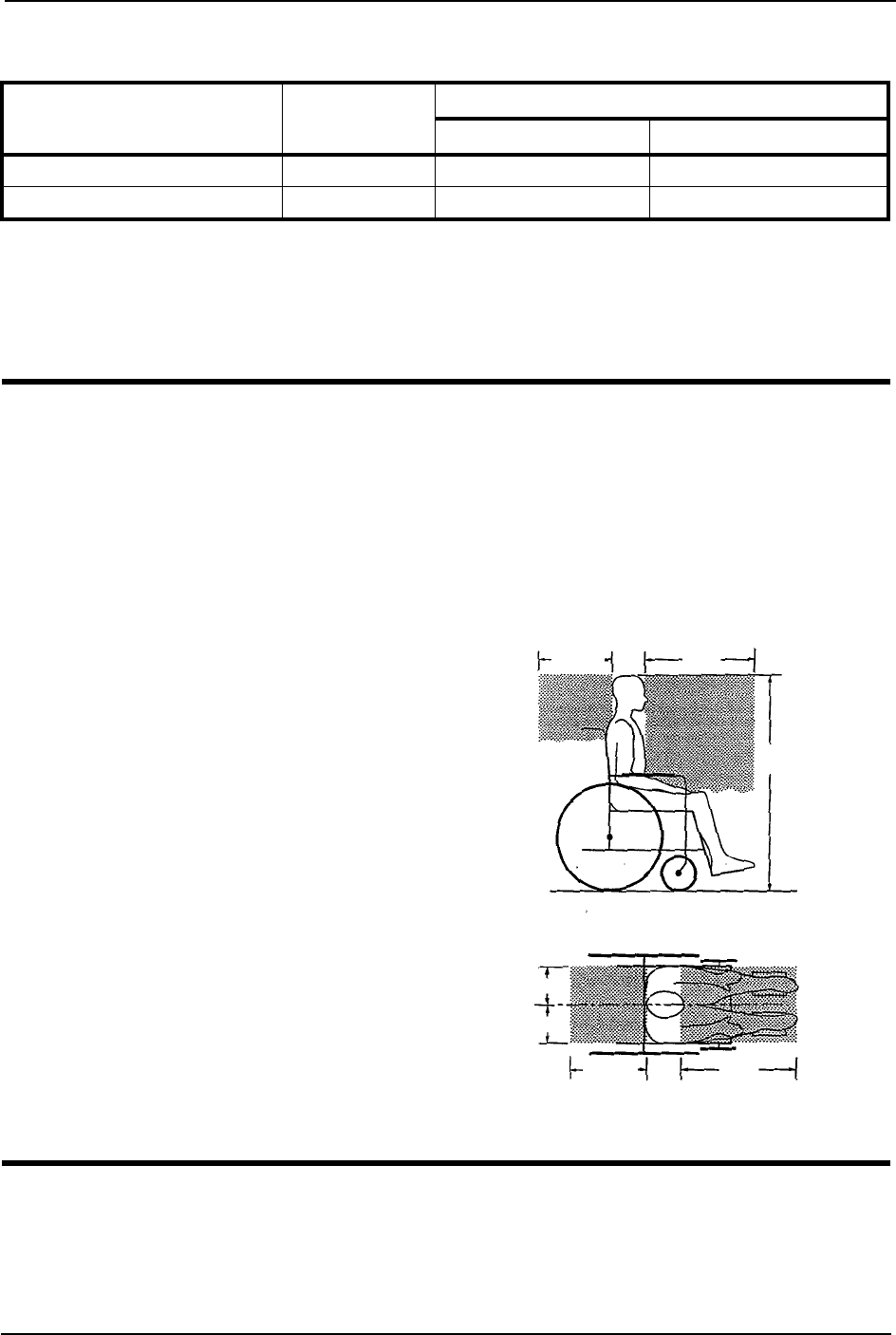
SECTION 11—TRANSPORT READY PACKAGE (TRRO)
TDX™ SP 66 Part No 1143190
Specifications
Securing the Wheelchair to the Vehicle
Positioning the Wheelchair in the Vehicle
WARNING
This wheelchair must be in a forward facing position during travel in a motor
vehicle.
The recommended clear zones for wheelchair seated occupants restrained by
BOTH pelvic and upper-torso belt(s) and ONLY by a pelvic belt are shown in the
diagrams and described below.
Frontal Clear Zones (FCZ) need to be
LARGER when upper-torso belt(s) are
NOT used.
The rear clear zone of 16-inches is
measured from the rearmost point on
an occupant’s head.
The frontal clear zone is measured from
the frontmost point on an occupant’s
head and is 26-inches with pelvic and
upper-torso belt(s) and 37-inches with
ONLY a pelvic belt.
The frontal clear zone may not be
achievable for wheelchair-seated
drivers.
The estimated seated height (HHT)
from the ground or floor to the top of
the wheelchair-seated occupant’s head
ranges from approximately 47-inches
for a small adult female to about 61-
inches for a tall adult male.
MODEL MOTOR WHEELCHAIR WEIGHT LIMIT
ADULT JUNIOR
TDX SP HD 4 Pole HD Up to 400 pounds N/A
TDX SP 4 Pole Up to 300 pounds Up to 150 pounds
16 in.
Frontal Clear
Zone
Side View
Top View
HHT
FCZ
Frontal Clear Zone
16 in.
8 in.
8 in.
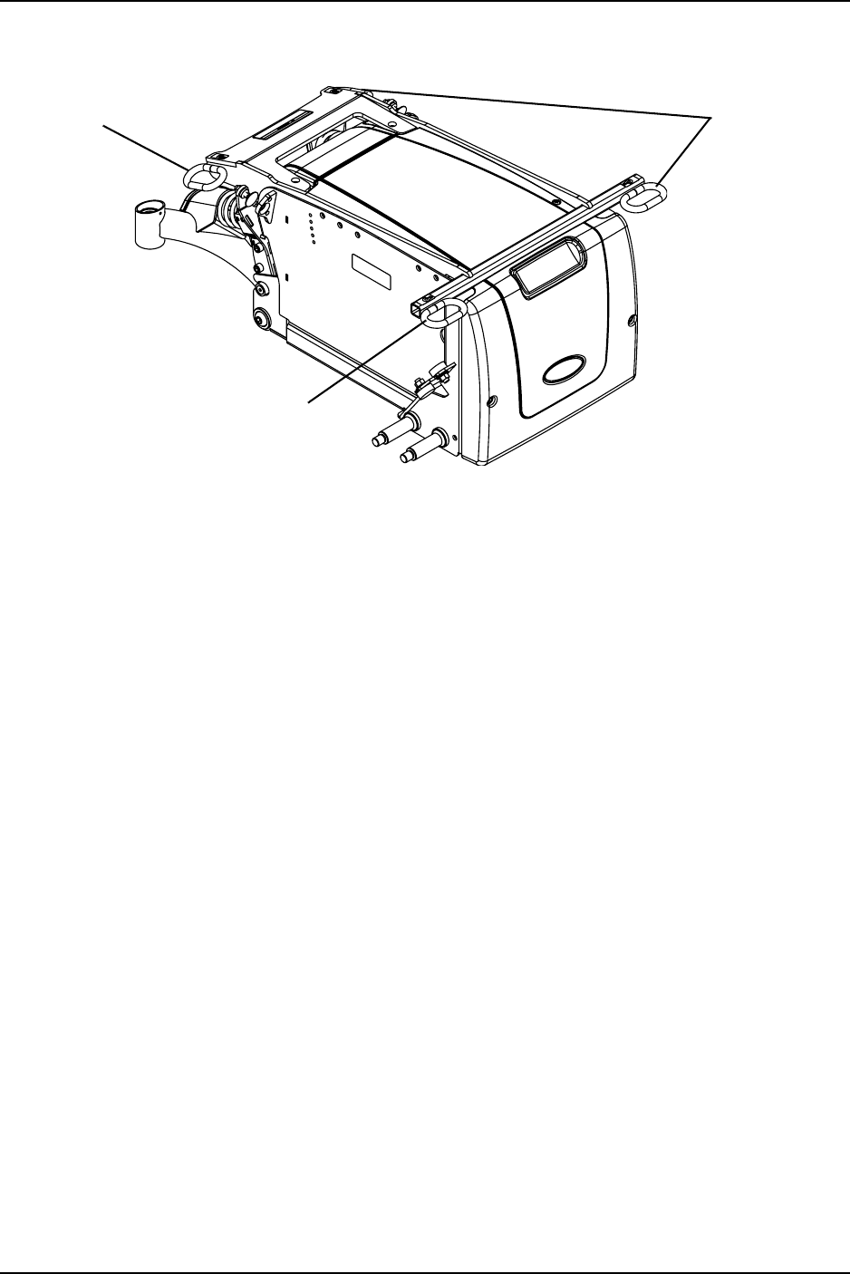
SECTION 11—TRANSPORT READY PACKAGE (TRRO)
Part No 1143190 67 TDX™ SP
Securement Points
FIGURE 11.1 Securement Points
Securing the Wheelchair
ThiswheelchairistobeusedonlywithWheelchairTie‐downandOccupantRestraint
Systems(WTORS)thathavebeeninstalledinaccordancewiththemanufacturerʹs
instructionsandSAEJ2249.
NOTE:AcopyofSAEJ2249WheelchairTie‐downandOccupantRestraintSystems(WTORS)
foruseinMotorVehiclescanbeobtainedfrom:SAEInternational,400CommonwealthDrive,
Warrendale,PA 15096‐0001,(877)606‐7232or(724)776‐4970.
AttachWTORStothetie‐downbracketsinaccordancewiththemanufacturerʹs
instructionsandSAEJ2249.
Tie-Down
Bracket
Tie-Down
Brackets
Tie-Down
Bracket

SECTION 11—TRANSPORT READY PACKAGE (TRRO)
TDX™ SP 68 Part No 1143190
Securing the Occupant
Wheelchair-Anchored Belts
WARNING
The pelvic belt that is provided by Invacare has been tested for use in a motor vehi-
cle on this wheelchair ONLY. DO NOT replace the pelvic belt with a different style
pelvic belt.
NOTE:Forthisprocedure,refertoFIGURE 11.2onpage 69.
Thewheelchairhasbeenprovidedwithapelvicbeltwhichmeetstherequirementsof
ANSI/RESNAW/C19.
Thepelvicbelt,providedbyInvacare,hasbeendesignedtoaccommodateuseoneither
sideofthevehicle.Ifnecessary,followtheinstructionsbelowtoreversetheorientationof
thepelvicbelttoaccommodatethevehicle‐anchoredupper‐torsobelt.
1. Installthepelvicbeltpin(Detail“A”ofFIGURE 11.2)intothelargeendoftheslotin
thebeltmountingbracket(Detail“B”orDetail“C”).Rotatedownwardandforward
untilitsnapsintoplaceintothesmallendoftheslot.
NOTE:Notethepositionofthemaleendofthebeltwheninstallingthepelvicbeltontothebelt
mountingbrackets.Themaleendofthepelvicbelt(DetailʺAʺofFIGURE 11.2)hasapinwhich
isusedtosecurethevehicle‐anchoredupper‐torsobelt.
2. RepeatSTEP1fortheoppositebeltmountingbracket.
3. Installthevehicle‐anchoredupper‐torsobeltontothepinonthemaleendofthepelvic
belt.
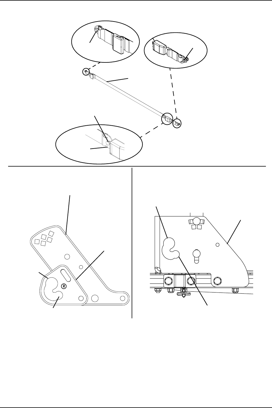
SECTION 11—TRANSPORT READY PACKAGE (TRRO)
Part No 1143190 69 TDX™ SP
FIGURE 11.2 Wheelchair-Anchored Belts
Pin Pin
Pin
(Used to secure the vehicle anchored
upper-torso belt)
Male End
DETAIL “A”
Back Angle
Bracket
Large End
of Slot
Belt Mounting
Bracket
Small End of Slot
Pelvic Belt
Large End
of Slot Belt Mounting
Bracket
Small End of Slot
DETAIL “B” - ADULT SEATS DETAIL “C” - JUNIOR SEATS
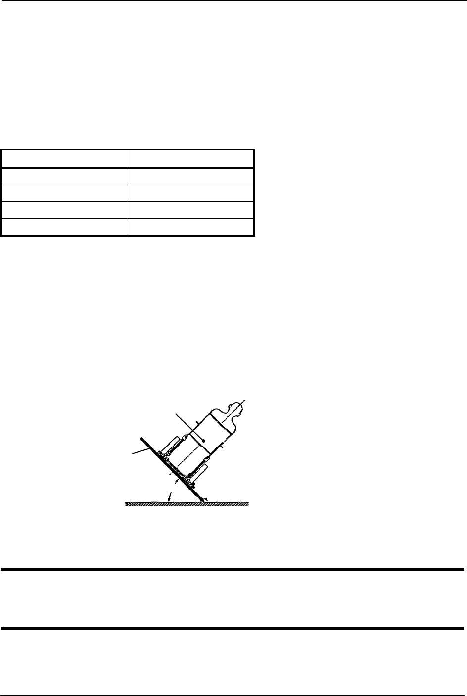
SECTION 11—TRANSPORT READY PACKAGE (TRRO)
TDX™ SP 70 Part No 1143190
Vehicle-Anchored Belts
NOTE:Forthisprocedure,refertoFIGURE 11.3.
Withregardtoaccommodatingtheuseandfitofvehicle‐anchoredbelts,thiswheelchair
hasanoverallratingof:
•TDXSPAdult‐A
•TDXSPJunior‐B
Thisratingisscoredasfollows:
ThetestforLateralStabilityDisplacementforPoint(P)isshowninFIGURE 11.3.The
averagetestresultforpoint(P)is:
•TDXSPwithTwo22NFBatteries‐
•TDXSPAdult‐0.53‐inches(13.4mm)
•TDXSPJunior‐0.57inches(14.4mm)
•TDXSPwithTwoGP24Batteries‐
•TDXSPAdult‐0.54‐inches(13.7mm)
•TDXSPJunior‐0.51inches(12.95mm)
FIGURE 11.3 Vehicle-Anchored Belts
Seating System
WARNING
This wheelchair has been tested for seating in a motor vehicle with the factory
installed seating system ONLY.
Ensurethatthefactoryinstalledseatingsystemissecuredtothewheelchairframebefore
operation.Refertotheseatingsystemowner’smanual.
RATING DESCRIPTION
AExcellent
BGood
CFair
DPoor
Point (P)
Test Platform
45°
NOTE:Rearviewofthe
wheelchairandhuman
surrogatesecuredontest
platformandtiltedto45°.
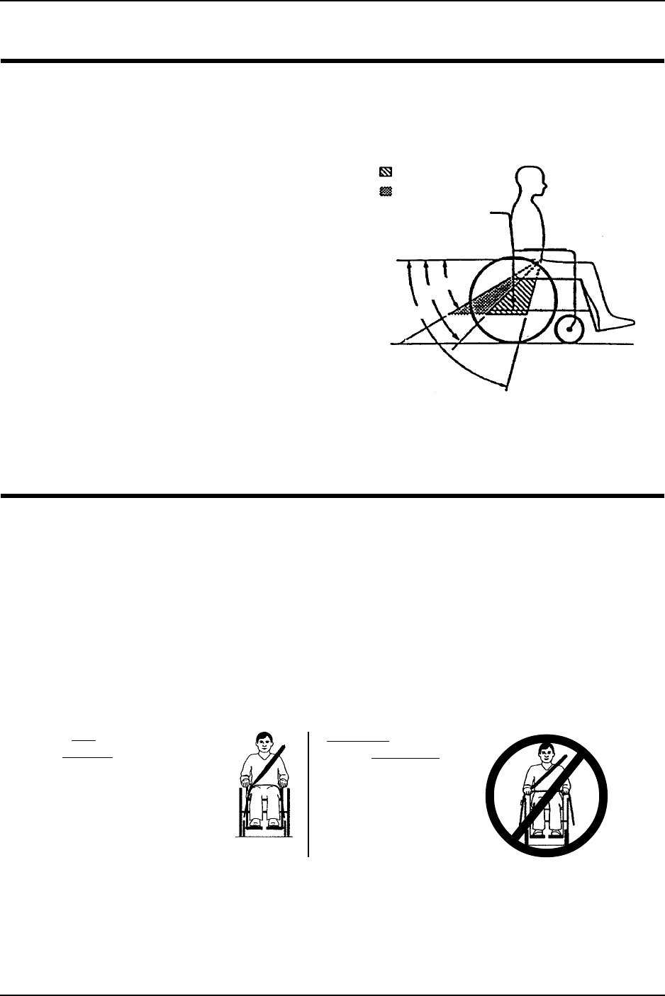
SECTION 11—TRANSPORT READY PACKAGE (TRRO)
Part No 1143190 71 TDX™ SP
Positioning Belts
WARNING
The angle of the pelvic belt should be
within the preferred zone of 45 to 75
degrees to the horizontal OR within the
optional zone of 30 to 45 degrees to the
horizontal.
Steeper side-view pelvic belt angles are
especially important if the pelvic belt is
intended to be used for postural support
in addition to occupant restraint in a
frontal crash. Steeper angles will reduce
the tendency for a vertical gap to
develop between the user and the belt
due to compliance of seat cushions and
belt movement, thereby reducing the
tendency for the user to slip under the
belt and for the belt to ride up on the
soft abdomen during normal use.
Steeper belt angles also reduce the tendency for upper-torso belts to pull the pelvic
belt onto the abdomen during frontal impact loading.
NOTE:Forthisprocedure,refertoFIGURE 11.4.
1. Thepelvicbeltshouldbewornlowacrossthefrontofthepelvis.
2. Positiontheupper‐torsobelt(s)overtheshoulders.
3. Thebelt(s)shouldnotbeheldawayfromthebodybywheelchaircomponentsor
parts,includingbutnotlimitedtowheelchairarmrestsorwheels.Referto
FIGURE 11.4forproperandimproperpositioningofthebelts.
4. Ensurethebelt(s)arenottwisted.
5. Adjustbeltsasfirmlyaspossible,beingmindfulofusercomfort.
FIGURE 11.4 Positioning Belts
Preferred Zone
Optional Zone
Side View
30°
45°
70°
DO POSITION BELT
INSIDE OF ARMRESTS,
WHEELS, ETC.
DO NOT POSITION
BELT OUTSIDE OF
ARMRESTS, WHEELS,
ETC.

LIMITED WARRANTY
PLEASE NOTE: THE WARRANTY BELOW HAS BEEN DRAFTED TO COMPLY WITH FEDERAL LAW
APPLICABLE TO PRODUCTS MANUFACTURED AFTER JULY 4, 1975.
This warranty is extended only to the original purchaser who purchases this product when new and unused from
Invacare or a dealer. This warranty is not extended to any other person or entity and is not transferable or
assignable to any subsequent purchaser or owner. Coverage under this warranty will end upon any such
subsequent sale or other transfer of title to any other person.
This warranty gives you specific legal rights and you may also have other legal rights which vary from state to state.
Invacare warrants the base frame to be free from defects in materials and workmanship for a period of five (5)
years from the date of purchase from Invacare or a dealer, with a copy of the seller’s invoice required for coverage
under this warranty. Invacare warrants all electronics and electrical components (excluding batteries), motors,
powered seating actuators and gearboxes for a period of one (1) year from the date of purchase from Invacare or
a dealer, with a copy of the seller’s invoice required for coverage under this warranty. Invacare warrants all
batteries for a period of six (6) months from the date of purchase from Invacare or a dealer, with a copy of the
seller’s invoice required for coverage under this warranty. Invacare warrants all remaining components (excluding
all upholstered materials, padded materials, tires and wheels) for a period of one (1) year from the date of
purchase from Invacare or a dealer, with a copy of the seller’s invoice required for coverage under this warranty. If
within such warranty periods any such product component shall be proven to be defective, the product
component shall be repaired or replaced, at Invacare's option. This warranty does not include any labor or
shipping charges incurred in replacement part installation or repair of any such product. Invacare's sole obligation
and your exclusive remedy under this warranty shall be limited to such repair and/or replacement.
For warranty service, please contact the dealer from whom you purchased your Invacare product. In the event you
do not receive satisfactory warranty service, please write directly to Invacare at the address on the bottom of the
back cover. Provide dealer's name address, date of purchase, indicate nature of the defect and, if the product is
serialized, indicate the serial number. Do not return products to our factory without our prior consent.
LIMITATIONS AND EXCLUSIONS: THE FOREGOING WARRANTY SHALL NOT APPLY TO SERIAL
NUMBERED PRODUCTS IF THE SERIAL NUMBER HAS BEEN REMOVED OR DEFACED, PRODUCTS
SUBJECT TO NEGLIGENCE, ACCIDENT, IMPROPER OPERATION, MAINTENANCE OR STORAGE,
COMMERCIAL OR INSTITUTIONAL USE, PRODUCTS MODIFIED WITHOUT INVACARE'S EXPRESS
WRITTEN CONSENT (INCLUDING, BUT NOT LIMITED TO, MODIFICATION THROUGH THE USE OF
UNAUTHORIZED PARTS OR ATTACHMENTS); PRODUCTS DAMAGED BY REASON OF REPAIRS MADE
TO ANY COMPONENT WITHOUT THE SPECIFIC CONSENT OF INVACARE, OR TO A PRODUCT
DAMAGED BY CIRCUMSTANCES BEYOND INVACARE'S CONTROL, AND SUCH EVALUATION WILL BE
SOLELY DETERMINED BY INVACARE. THE WARRANTY SHALL NOT APPLY TO PROBLEMS ARISING
FROM NORMAL WEAR AND TEAR OR FAILURE TO ADHERE TO THE PRODUCT INSTRUCTIONS. A
CHANGE IN OPERATING NOISE, PARTICULARLY RELATIVE TO MOTORS AND GEARBOXES DOES NOT
CONSTITUTE A FAILURE OR DEFECT AND WILL NOT BE REPAIRED; ALL DEVICES WILL EXHIBIT
CHANGES IN OPERATING NOISE DUE TO AGING.
THE FOREGOING EXPRESS WARRANTY IS EXCLUSIVE AND IN LIEU OF ANY OTHER WARRANTIES
WHATSOEVER, WHETHER EXPRESS OR IMPLIED, INCLUDING THE IMPLIED WARRANTIES OF
MERCHANTABILITY AND FITNESS FOR A PARTICULAR PURPOSE, AND THE SOLE REMEDY FOR
VIOLATIONS OF ANY WARRANTY WHATSOEVER, SHALL BE LIMITED TO REPAIR OR REPLACEMENT
OF THE DEFECTIVE PRODUCT PURSUANT TO THE TERMS CONTAINED HEREIN. THE APPLICATION
OF ANY IMPLIED WARRANTY WHATSOEVER SHALL NOT EXTEND BEYOND THE DURATION OF THE
EXPRESS WARRANTY PROVIDED HEREIN AND INVACARE SHALL NOT BE LIABLE FOR ANY
CONSEQUENTIAL OR INCIDENTAL DAMAGES WHATSOEVER; SOME STATES DO NOT ALLOW THE
EXCLUSION OR LIMITATION OF INCIDENTAL OR CONSEQUENTIAL DAMAGE, OR LIMITATION OF
HOW LONG AN IMPLIED WARRANTY LASTS, SO THE ABOVE EXCLUSION AND LIMITATION MAY NOT
BE APPLICABLE.
THIS WARRANTY SHALL BE EXTENDED TO COMPLY WITH STATE/PROVINCIAL LAWS AND
REQUIREMENTS.
Invacare Corporation www.invacare.com
USA
One Invacare Way
Elyria, Ohio USA
44036-2125
800-333-6900
Canada
570 Matheson Blvd E Unit 8
Mississauga Ontario
L4Z 4G4 Canada
800-668-5324
Invacare, SureStep, Yes, you can. and
the Medallion Design are registered
trademarks of Invacare Corporation.
TDX, MK6i, MPJ, SPJ and Formula are
trademarks of Invacare Corporation
© 2007 Invacare Corporation.
Part No 1143190
Rev C - 02/21/07
