Invacare Tracer Ex2 Users Manual 1110546E
EX2 to the manual 03ccb21d-a502-37c4-e917-9e08f2d5dc11
2015-02-02
: Invacare Invacare-Tracer-Ex2-Users-Manual-433686 invacare-tracer-ex2-users-manual-433686 invacare pdf
Open the PDF directly: View PDF ![]() .
.
Page Count: 40
- Special Notes
- Label Location
- typical product parameters
- Section 1— General Guidelines
- Section 2— Safety/handling of wheelchairs
- Section 3— Safety Inspection/troubleshooting
- Section 4— Front Riggings
- Section 5— Arms
- Section 6— Seat and Back
- Section 7— Rear Wheels
- Section 8— Front Casters
- Section 9— Anti-tippers/Wheel Locks
- Section 10— Seat to floor
- Section 11— Options
- LIMITED WARRANTY

Owner’s Operator and Maintenance Manual
DEALER: This manual MUST be given to
the user of the wheelchair.
USER: BEFORE using this wheelchair, read
this manual and save for future reference.
For more information regarding
Invacare products, parts, and services,
please visit www.invacare.com
SPECIAL NOTES ........................................................................................3
LABEL LOCATION .....................................................................................4
TYPICAL PRODUCT PARAMETERS .............................................................5
SECTION 1—GENERAL GUIDELINES ............................................................6
SECTION 2—SAFETY/HANDLING OF WHEELCHAIRS ....................................9
SECTION 3—SAFETY INSPECTION/TROUBLESHOOTING ............................ 15
SECTION 4—FRONT RIGGINGS ................................................................ 19
SECTION 5—ARMS .................................................................................. 24
SECTION 6—SEAT AND BACK ................................................................. 26
SECTION 7—REAR WHEELS ...................................................................... 30
SECTION 8—FRONT CASTERS .................................................................. 32
SECTION 9—ANTI-TIPPERS/WHEEL LOCKS ................................................ 34
SECTION 10—SEAT TO FLOOR ................................................................. 37
SECTION 11—OPTIONS ........................................................................... 38
LIMITED WARRANTY .............................................................................. 40
Tracer EX2

Tracer® EX2 2Part No. 1110546
WARNING
A QUALIFIED TECHNICIAN MUST PERFORM THE INITIAL SET UP OF THIS
WHEELCHAIR. ALSO, A QUALIFIED TECHNICIAN MUST PERFORM ALL
PROCEDURES SPECIFICALLY INDICATED IN THE MANUAL.
WHEELCHAIR USERS: DO NOT SERVICE OR OPERATE THIS EQUIPMENT
WITHOUT FIRST READING AND UNDERSTANDING (1) THE OWNER’S
OPERATOR AND MAINTENANCE MANUAL AND (2) THE SEATING
SYSTEM’S MANUAL (IF APPLICABLE). IF YOU ARE UNABLE TO
UNDERSTAND THE WARNINGS, CAUTIONS, AND INSTRUCTIONS,
CONTACT INVACARE TECHNICAL SUPPORT BEFORE ATTEMPTING TO
SERVICE OR OPERATE THIS EQUIPMENT - OTHERWISE INJURY OR
DAMAGE MAY RESULT.
DEALERS AND QUALIFIED TECHNICIANS: DO NOT SERVICE OR OPERATE
THIS EQUIPMENT WITHOUT FIRST READING AND UNDERSTANDING (1)
THE OWNER’S OPERATOR AND MAINTENANCE MANUAL, (2) THE SERVICE
MANUAL (IF APPLICABLE) AND (3) THE SEATING SYSTEM’S MANUAL (IF
APPLICABLE). IF YOU ARE UNABLE TO UNDERSTAND THE WARNINGS,
CAUTIONS AND INSTRUCTIONS, CONTACT INVACARE TECHNICAL
SUPPORT BEFORE ATTEMPTING TO SERVICE OR OPERATE THIS
EQUIPMENT - OTHERWISE, INJURY OR DAMAGE MAY RESULT.
ACCESSORIES WARNING
Invacare products are specifically designed and manufactured for use in
conjunction with Invacare accessories. Accessories designed by other
manufacturers have not been tested by Invacare and are not recommended for use
with Invacare products.
NOTE:Updatedversionsofthismanualareavailableonwww.invacare.com.

SPECIAL NOTES
Part No. 1110546 3Tracer® EX2
SPECIAL NOTES
Signalwordsareusedinthismanualandapplytohazardsorunsafepracticeswhichcouldresultinpersonalinjuryor
propertydamage.Refertothefollowingtablefordefinitionsofthesignalwords.
NOTICE
THE INFORMATION CONTAINED IN THIS DOCUMENT IS SUBJECT TO CHANGE
WITHOUT NOTICE.
WHEELCHAIR USER
As a manufacturer of wheelchairs, Invacare endeavors to supply a wide variety of wheelchairs to
meet many needs of the end user. However, final selection of the type of wheelchair to be used
by an individual rests solely with the user and his/her healthcare professional capable of making
such a selection.
WHEELCHAIR TIE-DOWN RESTRAINTS AND SEAT POSITIONING STRAPS
Wheelchair users should NOT be transported in vehicles of any kind while in wheelchairs. As of
this date, the Department of Transportation has not approved any tie-down systems for
transportation of a user while in a wheelchair, in a moving vehicle of any type.
It is Invacare’s position that users of wheelchairs should be transferred into appropriate seating
in vehicles for transportation and use be made of the restraints made available by the auto
industry. Invacare cannot and does not recommend any wheelchair transportation systems.
ALWAYS wear your seat positioning strap. Inasmuch as the seat positioning strap is an option on
this wheelchair (you may order with or without the seat positioning strap), Invacare strongly
recommends ordering the seat positioning strap as an additional safeguard for the wheelchair
user. The seat positioning strap is a positioning strap only. It is not designed for use as a safety
device withstanding high stress loads such as auto or aircraft safety belts. If signs of wear appear,
strap MUST be replaced IMMEDIATELY.
With regards to seat/chest positioning straps - it is the obligation of the DME dealer, therapists
and other healthcare professionals to determine if a seat/chest positioning strap is required to
ensure the safe operation of this equipment by the user. Serious injury can occur in the event of
a fall from a wheelchair.
SIGNAL WORD MEANING
DANGER Danger indicates an imminently hazardous situation which, if not avoided, will result in death or serious
injury.
WARNING Warning indicates a potentially hazardous situation which, if not avoided, could result in death or serious
injury.
CAUTION Caution indicates a potentially hazardous situation which, if not avoided, may result in property damage,
minor injury or both
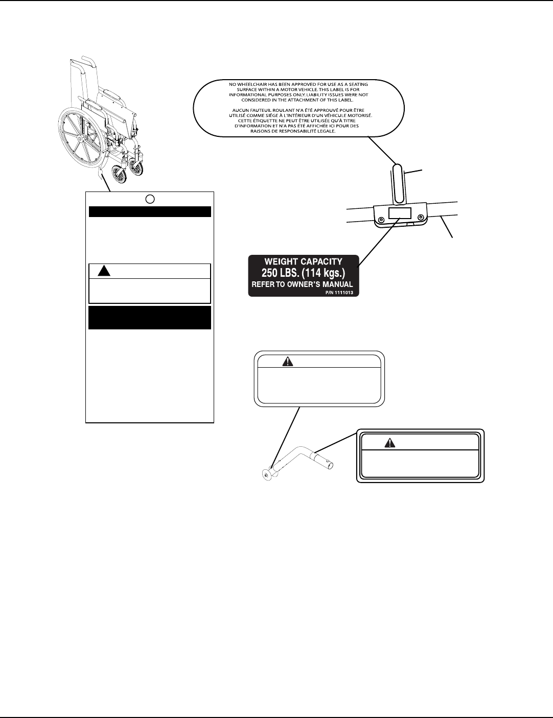
LABEL LOCATION
Tracer® EX2 4Part No. 1110546
LABEL LOCATION
IMPORTANT NOTICE
The wheel locks on this wheelchair have been
pre-set at the factory to comply with the
Veterans Administration functional Standard
8320.01 of the Federal Register, paragraph
3.2.4.5.3. If these wheel locks do not meet
your needs, follow instructions below.
!
CAUTION
Any wheel lock adjustments should embed
wheel lock shoe at least 1/8" into tire when
locked (3/16" on pneumatic tires).
INSTRUCTIONS FOR WHEEL
LOCK ADJUSTMENTS
1. Loosen wheel lock mounting fastener,
which runs through mounting bracket and
frame.
2. Slide clamp toward rear wheel until wheel
lock shoe is embedded into tire material at
least 1/8" when handle is engaged to the
lock position (3/16" for pneumatic tires).
3. Tighten mounting fastener to secure
mounting bracket in desired location and
recheck lock shoe embedding.
4. Inspect for correct locking action BEFORE
actual use.
00078X021-0394
Refer to Owner's Manual
for proper anti-tipper
setting.
1085379
WARNING
WARNING
DO NOT OPERATE WITHOUT
THE ANTI-TIP TUBES
INSTALLED.
REV. 5/98 P/N 60106X144
Crossmember
Lower Frame
Tube
NOTE:Onalladjustable
anti‐tippers

TYPICAL PRODUCT PARAMETERS
Part No. 1110546 5Tracer® EX2
TYPICAL PRODUCT PARAMETERS
*NOTE:Theseoptionsarestandardforthismodel.
**NOTE:Theseat‐to‐floorheightsarebasedonurethanetires.Theseheightscanvary+/‐1/4 inchduetotirewear
andmanufacturingtolerances.
***NOTE:Weightsbasedon18‐inchwidewheelchairwithoutfrontriggings.Weightswillvarydependingon
howwheelchairisequipped.
OVERALL WIDTH
PERMANENT ARM:
REMOVABLE ARM: 231/4, 251/4, 27 1/4nches
241/4, 261/4, 281/4 inches
OVERALL DEPTH (WITH RIGGINGS) 317/8 inches
SEAT WIDTH 16, 18 or 20 inches
SEAT DEPTH
SA FRAME:
FF FRAME:
16 inches
16 inches
SEAT-TO-FLOOR (WITH 24-INCH
WHEELS)
ADULT: (SA FRAME):
ADULT: (FF FRAME):
HEMI: (SA FRAME):
191/2 inches
21 inches
171/2 inches
BACK STYLE Fixed
BACK HEIGHT 16 inches
ARM STYLES Fixed or Adjustable Height; Desk or Full Length; Permanent or Removable
FRONT RIGGINGS Swingaways Footrests, Elevating Legrests, (Not Available On FF Frame)
REAR AXLE Permanent
REAR WHEELS 24-inch Composite or Urethane
HANDRIMS Composite*
WHEEL LOCKS Push to Lock* (Adult), Pull to Lock* (Hemi)
CASTER SIZE 8x1-inch Solid Rubber
UPHOLSTERY Vinyl - Midnight Blue
FRAME COLORS Chrome* and colors
WEIGHT*** (APPROX.)
PERMANENT ARM:
REMOVABLE ARM:
36 pounds (SA Frame), 37 pounds (FF Frame)
36 pounds (SA Frame)
SHIPPING WEIGHT*** (APPROX.)
PERMANENT ARM:
REMOVABLE ARM: 451/2 pounds (SA Frame), 461/2 pounds (FF Frame)
451/2 pounds (SA Frame)
WEIGHT LIMIT 250 lbs (114 kg)

SECTION 1—GENERAL GUIDELINES
Tracer® EX2 6Part No. 1110546
SECTION 1—GENERAL GUIDELINES
WARNING
This section contains important information for the safe operation and use of this product.
Stability - All Models
Thesize/positionofthefrontcasters,size/position
oftherearwheels,useofanti‐tippermodel,as
wellastheuserconditiondirectlyrelatetothe
stabilityofthewheelchair.Anychangetooneor
anycombinationofthesixmaycausethe
wheelchairtodecreaseinstability.These
adjustmentsMUSTbeperformedbyaqualified
technician.
Thevariousseat‐to‐floorheightsrequirespecific
settingsdependingonrearwheelsize,rearwheel
positionandfrontcastersize/position.These
adjustmentsMUSTbeperformedbyaqualified
technician.
Anti-Tippers
Anti‐tippersarespecifictothedifferentanglesand/orseat‐to‐floorheights.Refertothechartsin
Installing/AdjustingAnti‐tippersonpage 34forcorrectusageandadjustment.Iftheserequirements
cannotbeachieved,DONOTusethewheelchair.Contactaqualifiedtechnician.Ifchangingthe
seat‐to‐floorheight,thecorrectanti‐tippersMUSTbeusedtomaintaina11/2to2inchgroundclearance.
Anti‐tippersMUSTbeattachedatalltimes.Inasmuchastheanti‐tippersareanoptionforonthis
wheelchair(youmayorderwithorwithouttheanti‐tippers),Invacarestronglyrecommendsordering
theanti‐tippersasasafeguardforthewheelchairuser.
ALWAYSuseanti‐tippers.Whenoutdoorsonwet,softgroundorongravelsurfaces,antitippersmay
notprovidethesamelevelofprotectionagainsttipover.ExtracautionMUSTbeobservedwhen
traversingsuchsurfaces.
Operating Information
Afteranyadjustments,repairorserviceandbeforeuse,makesureallattachinghardwareistightened
securely‐otherwiseinjuryordamagemayresult.
Unlessotherwisenoted,allserviceandadjustmentshouldbeperformedwhilethewheelchairis
unoccupied.
Avoidstoringorusingthewheelchairnearopenflameorcombustibleproducts.Seriousinjuryor
damagetopropertymayresult.
ALWAYSkeephandsandfingersclearofmovingpartstoavoidinjury.
Todetermineandestablishyourparticularsafetylimits,practicebending,reachingandtransferring
activitiesinseveralcombinationsinthepresenceofaqualifiedhealthcareprofessionalbefore
attemptingactiveuseofthewheelchair.
NOTE:Whenchangestothe
lefthandcolumnoccur,follow
acrossthechartandrefertothe
procedurethatischecked(
)to
maintaintheproperstability,
safetyandhandlingofthe
wheelchair.
CASTER SIZE
CASTER POSITION
WHEEL SIZE
WHEEL POSITION
ANTI-TIPPERS
USER CONDITION
CASTER SIZE •XXXXX
CASTER POSITION X•XXXX
WHEEL SIZE XX • X XX
ANTI-TIPPERS XXX • XX
USER CONDITION XXX X X•

SECTION 1—GENERAL GUIDELINES
Part No. 1110546 7Tracer® EX2
Whencleaningrearcaneorhandgripareasuseonlyacleantowellightlydampenedwithcoolwater.
Verifythatgripsaredrypriortouse.Useofsoaporammoniabasedcleaningsolutionswillresultinthe
handgripsslidingoffthecaneassembly.Failuretoobservethiswarningmayresultininjurytotheuser
orbystanders.
Ifthewheelchairisexposedtoextremetemperature(above100°Forbelow32°F),highhumidityand/or
becomeswet,priortouse,ensurethatthehandgripsdonottwistonthehandle.Otherwise,damageor
injurymayoccur.
DONOTtraverse,climborgodownrampsorslopesgreaterthan9°.
DONOTattempttomoveupordownaninclinewithawater,iceoroilfilm.
DONOToperateonroads,streetsorhighways.
DONOTattempttorideovercurbsorobstacles.Doingsomaycauseyourwheelchairtotipoverand
causebodilyharmtoyouordamagetothewheelchair.
DONOTattempttoreachobjectsifyouhavetomoveforwardintheseat.
DONOTattempttoreachobjectsifyouhavetopickthemupfromthefloorbyreachingdownbetween
yourknees.
DONOTleanoverthetopofthebackupholsterytoreachobjectsbehindyou,asthismaycausethe
wheelchairtotipover.
DONOTshiftyourweightorsittingpositiontowarddirectionyouarereachingasthewheelchairmay
tipover.
DONOTattempttostopamovingwheelchairwithwheellocks.Wheellocksarenotbrakes.
DONOTtipthewheelchairwithoutassistance.
DONOTuseanescalatortomoveawheelchairbetweenfloors.Seriousbodilyinjurymayoccur.
Beforeattemptingtotransferinoroutofthewheelchair,everyprecautionshouldbetakentoreduce
thegapdistance.Turnbothcastersparalleltotheobjectyouaretransferringonto.Whentransferring
toandfromthewheelchair,ALWAYSengagebothwheellocks.
DONOTattempttoliftthewheelchairbyanyremovable(detachable)parts.Liftingbymeansofany
removable(detachable)partsofthewheelchairmayresultininjurytotheuserordamagetothe
wheelchair.
DONOTstandontheframeofthewheelchair.
DONOTusethefootplateasaplatform.Whengettinginoroutofthewheelchair,makesurethatthe
footplatesareintheupwardposition.
ALWAYSusethehandrimsforself‐propulsion.Inasmuchasthehandrimsareanoptiononthis
wheelchair(youmayorderwithorwithoutthehandrims),Invacarestronglyrecommendsorderingthe
handrimsasanadditionalsafeguardforthewheelchairuser.
Makesuredetentballsofthequick‐releasepinarefullyreleasedbeforeoperatingthewheelchair.
ALWAYSwearyourseatpositioningstrap.Inasmuchastheseatpositioningstrapisanoptiononthis
wheelchair(youmayorderwithorwithouttheseatpositioningstrap),Invacarestronglyrecommends
orderingtheseatpositioningstrapasanadditionalsafeguardforthewheelchairuser.Theseat
positioningstrapisapositioningbeltonly.Itisnotdesignedforuseasasafetydevicewithstanding
highstressloadssuchasautooraircraftsafetybelts.Ifsignsofwearappear,beltMUSTbereplaced
IMMEDIATELY.
ThedetentballsMUSTbeprotrudingpastthetopoftheseatplateassemblyforapositivelock.
Keepdetentballsclean.

SECTION 1—GENERAL GUIDELINES
Tracer® EX2 8Part No. 1110546
Weight Training/Weight Limitation
Invacaredoesnotrecommendtheuseofitswheelchairsasaweighttrainingapparatus.Invacare
wheelchairshavenotbeendesignedortestedasaseatforanykindofweighttraining.Ifoccupantuses
saidwheelchairasaweighttrainingapparatus,Invacareshallnotbeliableforbodilyinjuryordamage
tothewheelchairandthewarrantyisvoid.
TheTracerEX2wheelchairhasaweightlimitationof250lbs(114kg).

SECTION 2—SAFETY/HANDLING OF WHEELCHAIRS
Part No. 1110546 9Tracer® EX2
SECTION 2—SAFETY/HANDLING OF WHEELCHAIRS
Safety/Handling of Wheelchairs
Safetyandhandlingofthewheelchairrequirethecloseattentionofthewheelchairuseraswellastheassistant.Thismanual
pointsoutthemostcommonproceduresandtechniquesinvolvedinthesafeoperationandmaintenanceofthewheelchair.
Itisimportanttopracticeandmasterthesesafetechniquesuntilyouarecomfortableinmaneuveringaroundthefrequently
encounteredarchitecturalbarriers.
Usethisinformationonlyasabasicguide.Thetechniquesthatarediscussedonthefollowingpageshavebeenused
successfullybymany.
Individualwheelchairusersoftendevelopskillstodealwithdailylivingactivitiesthatmaydifferfromthosedescribedin
thismanual.Invacarerecognizesandencourageseachindividualtotrywhatworksbestforhim/herinovercoming
architecturalobstaclesthattheymayencounter.However,allwarningsandcautionsgiveninthismanualMUSTbeheeded.
Techniquesinthismanualareastartingpointforthenewwheelchairuserandassistantwith“safety”asthemostimportant
considerationforall.
Stability and Balance
WARNING
ALWAYS wear your seat positioning strap. Inasmuch as the seat positioning strap is an option on
this wheelchair (you may order with or without the seat positioning strap), Invacare strongly rec-
ommends ordering the seat positioning strap as an additional safeguard for the wheelchair user.
The seat positioning strap is a positioning belt only. It is not designed for use as a safety device
withstanding high stress loads such as auto or aircraft safety belts. If signs of wear appear, belt
MUST be replaced IMMEDIATELY.
Toassurestabilityandproperoperationofyourwheelchair,youMUSTmaintainproperbalanceatalltimes.Your
wheelchairhasbeendesignedtoremainuprightandstableduringnormaldailyactivitiesaslongasyoudonotmove
beyondthecenterofgravity.
Virtuallyallactivitieswhichinvolvemovementinthewheelchairhaveaneffectonthecenterofgravity.Invacare
recommendsusingseat/chestpositioningstrapsforadditionalsafetywhileinvolvedinactivitiesthatshiftyourweight.
DONOTleanforwardoutofthewheelchairanyfurtherthanthelengthofthearmrests.Makesurethecastersarepointing
intheforwardpositionwheneveryouleanforward.Thiscanbeachievedbyadvancingthewheelchairandthenreversing
itinastraightline.
Coping With Everyday Obstacles
Copingwiththeirritationofeverydayobstaclescanbealleviatedsomewhatbylearninghowtomanageyourwheelchair.
Keepinmindyourcenterofgravitytomaintainstabilityandbalance.
A Note to Wheelchair Assistants
Whenassistancetothewheelchairuserisrequired,remembertousegoodbodymechanics.Keepyourbackstraightand
bendyourkneeswhenevertippingthewheelchairortraversingcurbs,orotherimpediments.
DONOTattempttoliftthewheelchairbyanyremovable(detachable)parts.Liftingbymeansofanyremovable(detachable)
partsofthewheelchairmayresultininjurytotheuserordamagetothewheelchair.
Ifthewheelchairisexposedtoextremetemperature(above100°Forbelow32°F),highhumidityand/orbecomeswet,prior
touse,ensurehandgripsdonottwistonthewheelchair’shandle‐otherwisedamageorinjurymayoccur.
Also,beawareofdetachablepartssuchasarmrestsorlegrests.TheseMUSTNEVERbeusedtomovethewheelchairoras
liftingsupports,astheymaybeinadvertentlyreleased,resultinginpossibleinjurytotheuserand/orassistant(s).
Whenlearninganewassistancetechnique,haveanexperiencedassistanthelpyoubeforeattemptingitalone.
SECTION 2—SAFETY/HANDLING OF WHEELCHAIRS
Tracer® EX2 10 Part No. 1110546
WARNING
DO NOT attempt to reach objects if you have to move forward in the seat or pick them up from
the floor by reaching down between your knees.
The size/position of the front casters, size/position of the rear wheels, use of anti-tipper model, as
well as the user condition directly relate to the stability of the wheelchair. Any change to one or any
combination of the six may cause the wheelchair to decrease in stability. These adjustments MUST
be performed by a qualified technician.
Manyactivitiesrequirethewheelchairownertoreach,bendandtransferinandoutofthewheelchair.Thesemovements
willcauseachangetothenormalbalance,thecenterofgravity,andtheweightdistributionofthewheelchair.Todetermine
andestablishyourparticularsafetylimits,practicebending,reachingandtransferringactivitiesinseveralcombinationsin
thepresenceofaqualifiedhealthcareprofessionalbeforeattemptingactiveuseofthewheelchair.
Properpositioningisessentialforyoursafety.Whenreaching,leaning,orbendingforward,itisimportanttousethefront
castersasatooltomaintainstabilityandbalance.
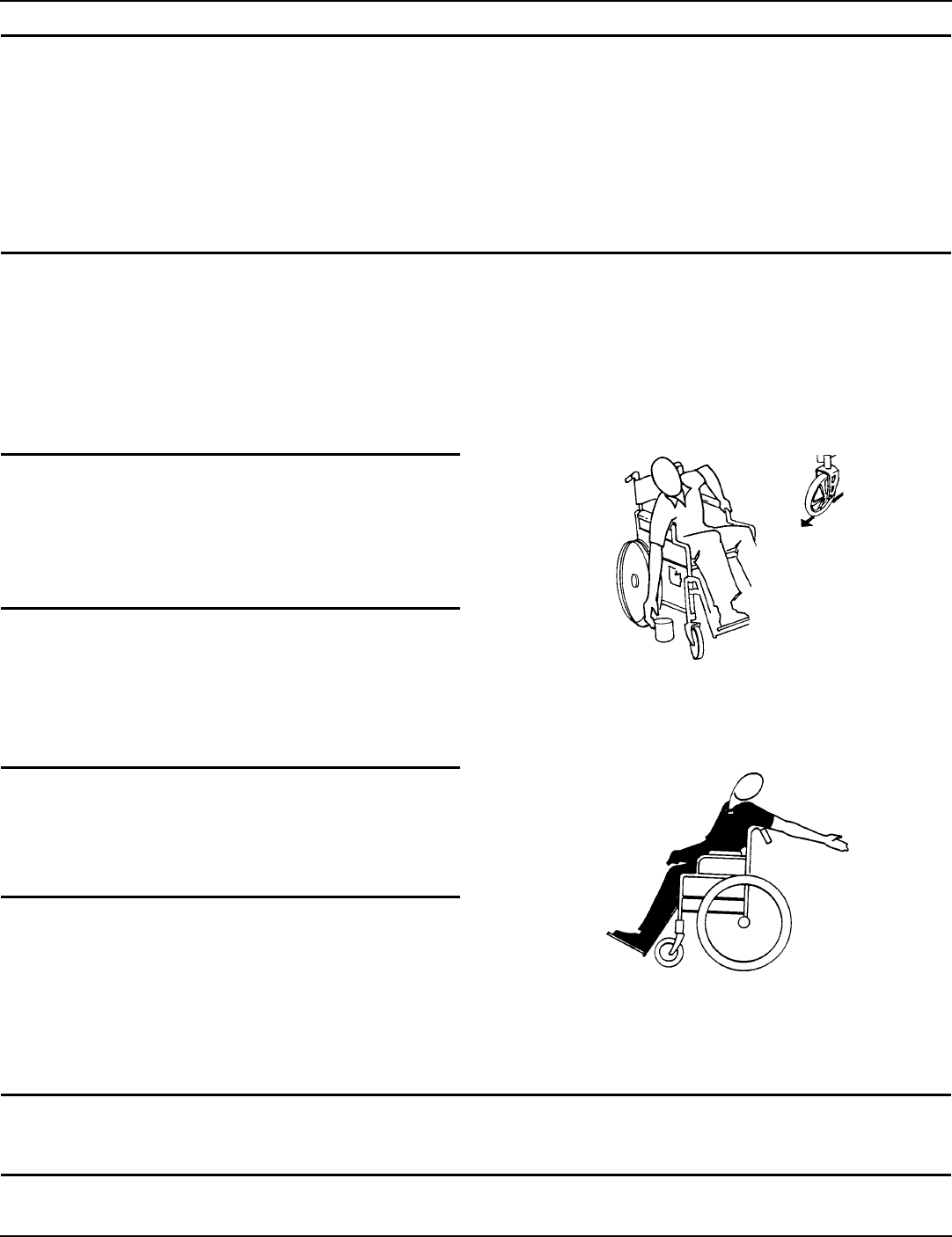
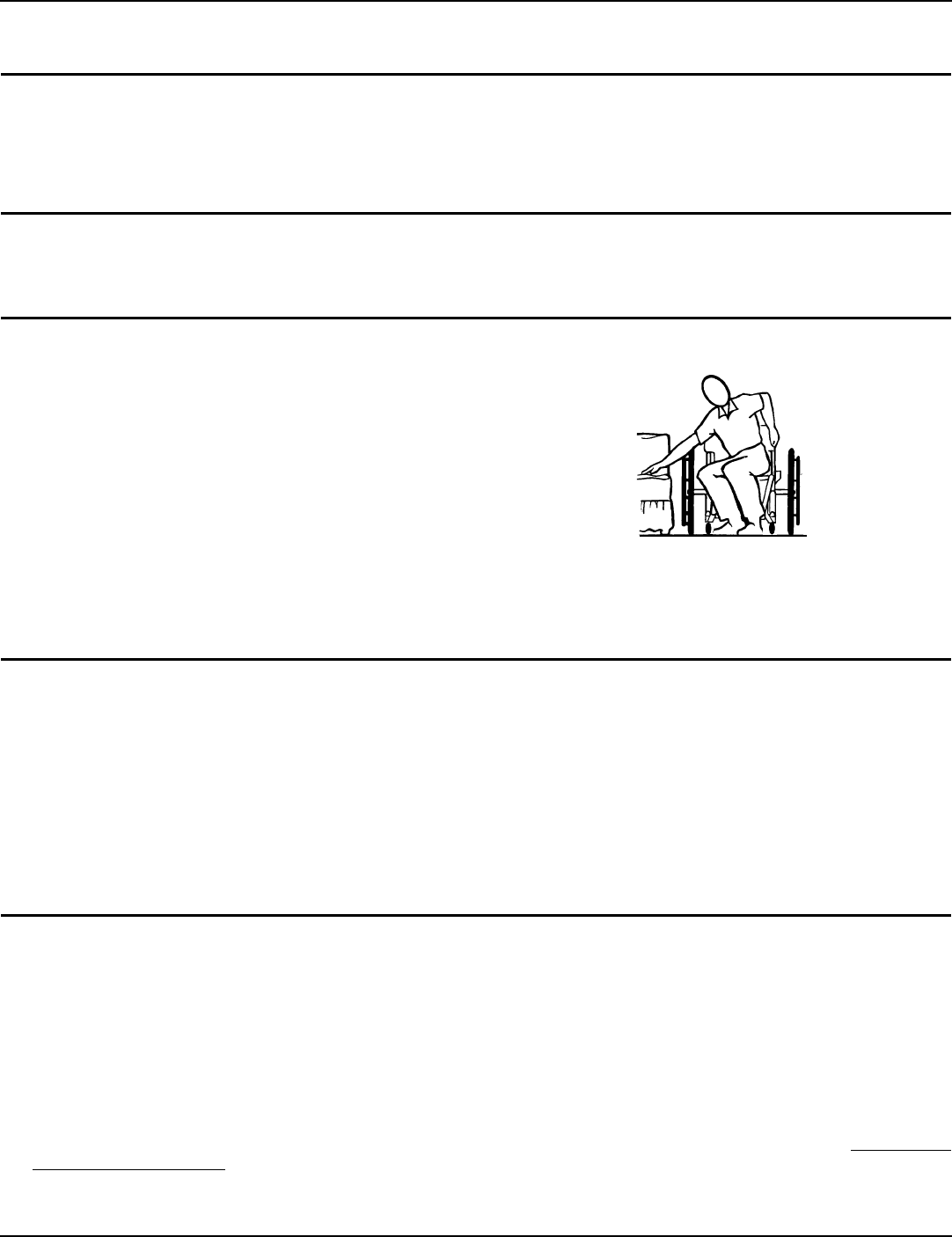
Reaching, Leaning and Bending Forward
WARNING
DO NOT attempt to reach objects if you have
to move forward in the seat or pick them up
from the floor by reaching down between your
knees.
NOTE:Forthisprocedure,refertoFIGURE 2.1.
Positionthefrontcasterssothattheyareextendedasfar
forwardaspossibleandengagewheellocks. FIGURE 2.1 Reaching, Leaning and Bending Forward
Reaching and Leaning Backwards
WARNING
DO NOT lean over the top of the back uphol-
stery to reach objects behind you, as this may
cause the wheelchair to tip over.
NOTE:Forthisprocedure,refertoFIGURE 2.2.
Positionwheelchairascloseaspossibletothedesired
object.Pointfrontcastersforwardtocreatethelongest
possiblewheelbase.Reachbackonlyasfarasyourarmwill
extendwithoutchangingyoursittingposition. FIGURE 2.2 Reaching and Leaning Backwards
Tipping
WARNING
DO NOT tip the wheelchair without assistance.
SECTION 2—SAFETY/HANDLING OF WHEELCHAIRS
Part No. 1110546 11 Tracer® EX2
Whentippingthewheelchair,anassistantshouldgraspthebackofthewheelchaironanon‐removable(non‐detachable)
part.Informthewheelchairoccupantbeforetippingthewheelchairandremindhim/hertoleanback.Besuretheoccupant’s
feetandhandsareclearofallwheelsand/orpinchpoints.
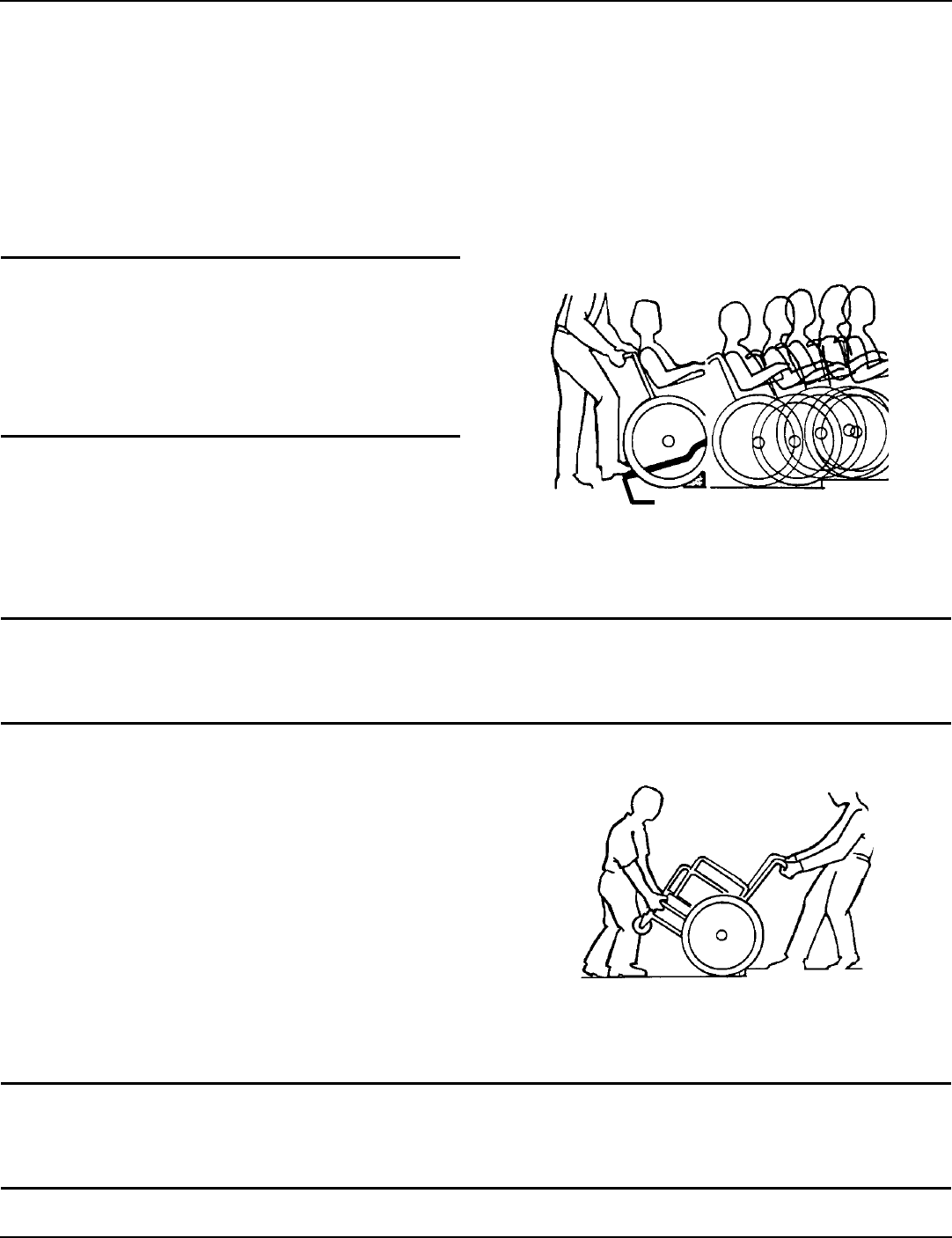
Aftermasteringthetechniquesoftippingthewheelchair,useoneofthefollowingmethodstotacklecurbs,shortstairs,etc.
Method 1 - Wheelchair With Step Tubes
NOTE:Forthisprocedure,refertoFIGURE 2.3.
Placefootonthesteptubeandbegintotiltthewheelchairtowardyou.Applyacontinuousdownwardmotionuntilthe
balancepointisachievedandthefrontcastersclearthecurb.Atthispoint,theassistantwillfeeladifferenceintheweight
distribution.
WARNING
When lowering the front casters of the wheel-
chair, DO NOT let the wheelchair drop the
last few inches to the ground. This could result
in injury to the occupant and/or damage to the
wheelchair.
Rollthewheelchairforwardandslowlylowerthefrontof
thewheelchairinonecontinuousmovementontothe
sidewalk.Pushthewheelchairforwarduntiltherearwheels
rollupandoverthecurb.
FIGURE 2.3 Method 1 - Wheelchair With Step Tubes
Method 2 - Wheelchair Without Step Tubes
WARNING
ALWAYS check hand grips for looseness before using the wheelchair. If loose and/or worn,
replace IMMEDIATELY.
NOTE:Forthisprocedure,refertoFIGURE 2.4.
Thismethodrequirestwoassistants.Thesecondassistant
shouldbepositionedatthefrontofthewheelchairlifting
upwardonanon‐removable(non‐detachable)partofthe
wheelchairframewhenliftingthewheelchairand
stabilizingthewheelchairwhenthewheelchairisbeing
loweredtotheground.
Thefirstassistantshouldstandonthesidewalkandturnthe
wheelchairsothattherearwheelsareagainstthecurb.Turn
theanti‐tipperssotheanti‐tipwheelsarepointingup.The
wheelchairshouldbetiltedbacktothebalancepointand,in
onecontinuousupwardmovement,therearwheelsshould
bepulledupandoverthecurb.DONOTreturnthefront
casterstothegrounduntilthewheelchairhasbeenpulled
backwardfarenoughforthefrontcasterstocleartheedge
ofthecurb.
FIGURE 2.4 Method 2 - Wheelchair Without Step
Tubes
WARNING
When lowering the front casters of the wheelchair, DO NOT let the wheelchair drop the last few
inches to the ground. This could result in injury to the occupant and/or damage to the wheelchair.
Step Tube
SECTION 2—SAFETY/HANDLING OF WHEELCHAIRS
Tracer® EX2 12 Part No. 1110546
Rollthewheelchairbackwardandslowlylowerthewheelchairinonecontinuousmovement.Turntheanti‐tipperssothe
anti‐tipwheelsarefacingdown.
Escalators
WARNING
DO NOT use an escalator to move a wheelchair between floors. Serious bodily injury may occur.
Stairways
WARNING
ALWAYS wear your seat positioning strap. Inasmuch as the seat positioning strap is an option on
this wheelchair (you may order with or without the seat positioning strap), Invacare strongly
recommends ordering the seat positioning strap as an additional safeguard for the wheelchair
user. The seat positioning strap is a positioning belt only. It is not designed for use as a safety
device withstanding high stress loads such as auto or aircraft safety belts. If signs of wear appear,
belt MUST be replaced IMMEDIATELY.
DO NOT attempt to lift a wheelchair by lifting on any removable (detachable) parts. Lifting by
means of any removable (detachable) parts of the wheelchair may result in injury to the user or
damage to the wheelchair.
ALWAYS check hand grips for looseness before using the wheelchair. If loose and/or worn,
replace IMMEDIATELY.
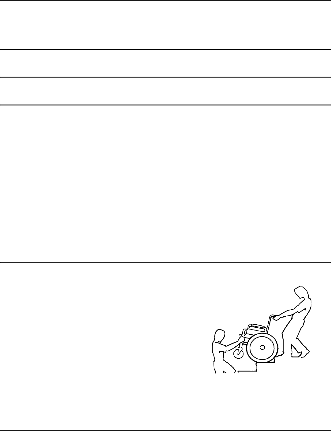
Extreme caution is advised when it is necessary to move an occupied wheelchair up or down the
stairs. Invacare recommends that, if possible, the user be removed from the wheelchair prior to
moving. Invacare recommends using two assistants and making thorough preparations. Make
sure to use only secure, non-detachable parts for hand-held supports.
NOTE:Forthisprocedure,refertoFIGURE 2.5.
Followthisprocedureformovingthewheelchairbetween
floorswhenanelevatorisnotavailable:
1. Ifnecessary,rotatetheanti‐tipperssothewheelsare
facingup.
2. Afterthewheelchairhasbeentiltedbacktothebalance
point,oneassistant(intherear)backsthewheelchair
upagainstthefirststep,whilesecurelygraspinga
non‐removable(non‐detachable)partofthewheelchair
forleverage.
3. Thesecondassistant,withafirmholdona
non‐detachablepartoftheframework,liftsthe
wheelchairupandoverthestairandsteadiesthe
wheelchairasthefirstassistantplacesonefootonthe
nextstairandrepeatsSTEP1.
4. Thewheelchairshouldnotbelowereduntilthelast
stairhasbeennegotiatedandthewheelchairhasbeen
rolledawayfromthestairway.
5. Ifnecessary,rotatetheanti‐tipperssothewheelsare
facingdown.
FIGURE 2.5 Stairways
SECTION 2—SAFETY/HANDLING OF WHEELCHAIRS
Part No. 1110546 13 Tracer® EX2
Transferring To and From Other Seats
WARNING
Before attempting to transfer in or out of the wheelchair, every precaution should be taken to
reduce the gap distance. Turn both casters parallel to the object you are transferring onto. Also
be certain the wheel locks are engaged to help prevent the wheels from moving.
CAUTION
When transferring, position yourself as far back as possible in the seat. This will help prevent
damaged upholstery and the possibility of the wheelchair tipping forward.
NOTE:Forthisprocedure,refertoFIGURE 2.6.
NOTE:Thisactivitymaybeperformedindependentlyprovided
youhaveadequatemobilityandupperbodystrength.
Positionthewheelchairascloseaspossiblealongsidethe
seattowhichyouaretransferring,withthefrontcasters
pointingparalleltoit.Removeorflipupthearmrest.
Engagewheellocks.Swingawayorremovefrontrigging.
Shiftbodyweightintoseatwithtransfer.
Duringindependenttransfer,littleornoseatplatformwill
bebeneathyou.Useatransferboardifatallpossible.
FIGURE 2.6 Transferring To and From Other Seats
Unfolding and Folding Wheelchair
WARNING
ALWAYS keep hands and fingers clear of moving parts to avoid injury.
DO NOT place hand or fingers on the underside of the seat frame rail when opening or closing
the wheelchair.
DO NOT sit or transfer into the wheelchair unless it is fully open and the seat frame rails are fully
seated into the side frame H-blocks.
Invacare recommends that a non-folding device be installed to keep the wheelchair from being
folded when left unoccupied in a public place.
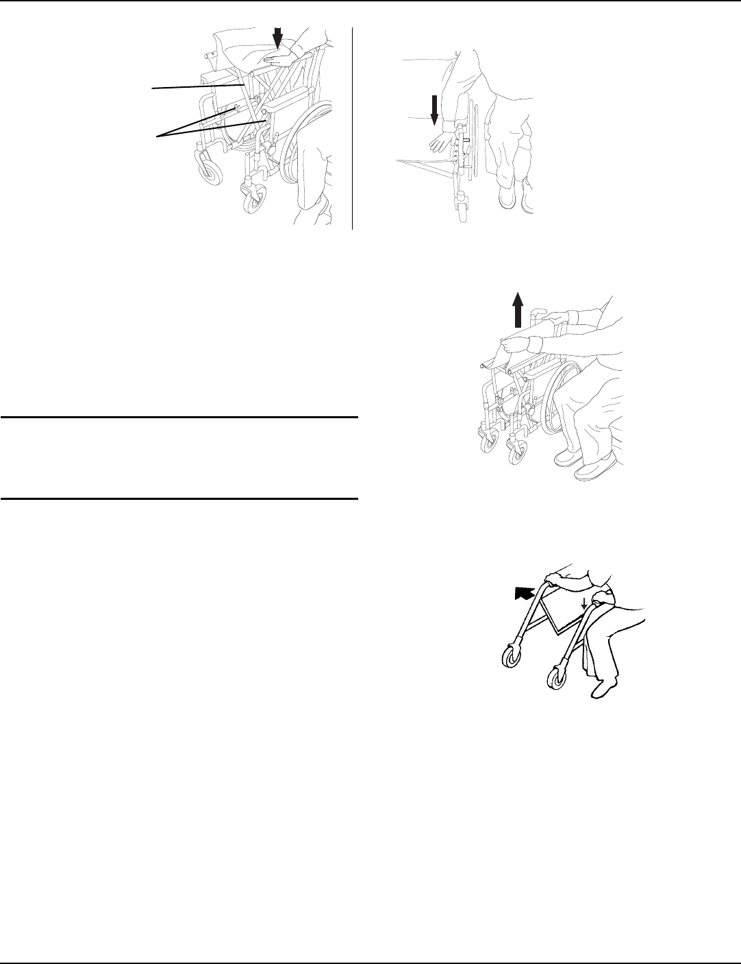
Unfolding
NOTE:Forthisprocedure,refertoFIGURE 2.7onpage14.
1. Tiltthewheelchairtowardyou(raisingtheoppositewheelandcasterofftheground/floor).
2. Placeyourhandonthetopoftheseatrailclosesttoyouwheretheseatupholsteryisattached.
3. Pointyourfingersandthumbtotheinsideofthewheelchair.
4. Pressdownwardonthetopoftheseatrailuntilthewheelchairisfullyopenandtheseatrailsarefullyseatedinthe
H‐blocks.
5. Engagebothwheellocks,openthefootrest/legrestforclearanceandtransferintothewheelchair.RefertoTransferring
ToandFromOtherSeatsonpage 13.
SECTION 2—SAFETY/HANDLING OF WHEELCHAIRS
Tracer® EX2 14 Part No. 1110546
FIGURE 2.7 Unfolding
Folding Wheelchair
NOTE:Forthisprocedure,refertoFIGURE 2.8.
1. Swingfootrest/legrestinlockedpositiontothefrontof
thewheelchair.
2. Pivotfootplatesupwardtoverticalposition.
3. Withbothhands,graspthemiddleoftheseat
upholsteryatthefrontandbackedgeandliftup.
CAUTION
DO NOT allow upholstery to hang between
the cross braces.
4. Placeexcessseatupholsteryoverthearmrest.
FIGURE 2.8 Folding Wheelchair
Folding Hammock or Sling Seat Models.
NOTE:Forthisprocedure,refertoFIGURE 2.9.
1. Swingfootrest/legrestandcalfpadsinlockedposition
tothefrontofthewheelchair.
2. Pivotfootplatesupwardtoverticalposition.
3. Withbothhands,graspthemiddleoftheseat
upholsteryatthefrontandbackedgeandliftup.
4. Continuetoclosethewheelchairbygraspingthe
armrestfurthestfromyouandpullingthearmrest
towardsyou. FIGURE 2.9 Folding Hammock or Sling Seat Models.
Seat Rail
NOTE:DONOTwrapthumbor
fingersundertheseatrail.Point
fingersandthumbtotheinsideof
thewheelchair.
NOTE:Pressdownontheseatrail
andtheseatupholsterywiththe
entirehand.DONOTplaceany
partofthehandundertheseatrail.
H-Blocks

SECTION 3—SAFETY INSPECTION/TROUBLESHOOTING
Part No. 1110546 15 Tracer® EX2
SECTION 3—SAFETY INSPECTION/TROUBLESHOOTING
NOTE:Everysixmonthsorasnecessary,takeyourwheelchairtoaqualifiedtechnicianforathoroughinspectionandservicing.Regular
cleaningwillreveallooseorwornpartsandenhancethesmoothoperationofyourwheelchair.Tooperateproperlyandsafely,your
wheelchairMUSTbecaredforjustlikeanyothervehicle.Routinemaintenancewillextendthelifeandefficiencyofyourwheelchair.
Safety Inspection Checklist
Initialadjustmentsshouldbemadetosuityourpersonalbodystructureandpreference.Thereafterfollowthese
maintenanceprocedures:
Inspect/Adjust Initially
❑Ensurethatthewheelchairrollsstraight(noexcessivedragorpulltooneside).
❑Inspectforlooseormissinghardwareonframeandcrossbraces.
❑Inspectforbentframeorcrossbraces.
❑Checkthatthewheellocksdonotinterferewithtireswhenrolling.
❑Checkthatthewheellockpivotpointsarefreeofwearandlooseness.
❑Checkthatthewheellocksareeasytoengage.
❑Ensurethatthewheellockspreventthewheelchairfrommovingwhenengaged.
❑Inspecttheseatandbackforripsandsagging.
❑Inspecttheseatandbackforlooseorbrokenhardware.
❑Inspectthebackcanehandgripsforwear/looseness/deterioration.
❑Inspectseatpositioningstrapforanysignsofwear.Ensurebucklelatches.Verifyhardwarethatattachesstraptoframe
issecureandundamaged.Replaceifnecessary.
❑Inspecttiresforflatspotsandwear.
❑Checkpneumatictiresforproperinflation.
CAUTION
As with any vehicle, check the wheels and tires periodically for cracks and wear. Replace if
damaged.
❑Ifequipped,checkthatquick‐releaseaxleslockproperly.Lubricateifnecessary.
❑Checkthatthereisnoexcessivesidemovementorbindingintherearwheelswhenliftedandspun.
❑Inspectrearwheelsforcracked,bentorbrokenspokes.
❑Ensureallspokesareuniformlytight.
❑Inspecthandrimsforsignsofroughedgesorpeeling.
❑Inspectaxleassemblyforpropertensionbyspinningcaster.Castershouldcometoagradualstop.
❑Adjustfrontcasters/forksbearingsystemifwheelwobblesnoticeablyorbindstoastop.
❑Ensurewheelbearingsarecleanandfreeofmoisture.
❑Checkheadtubelocknutsfortightness.
❑Inspectcastersforcracksandwear.
❑Inspectfrontcastersforcracked,bentorbrokenspokes.
❑Ensurethatcastersarefreeofdebris.
❑Cleanupholsteryandarmrests.
❑Checkthatalllabelsarepresentandlegible.Replaceifnecessary.

SECTION 3—SAFETY INSPECTION/TROUBLESHOOTING
Tracer® EX2 16 Part No. 1110546
Inspect/Adjust Weekly
❑Ensurethatthewheellockspreventthewheelchairfrommovingwhenengaged.
❑Inspecttiresforflatspotsandwear.
❑Checkpneumatictiresforproperinflation.
❑Ifequipped,checkthatquick‐releaseaxleslockproperly.Lubricateifnecessary.
❑Inspectrearwheelsforcracked,bentorbrokenspokes.
❑Ensureallspokesareuniformlytight.
❑Inspectaxleassemblyforpropertensionbyspinningcaster.Castershouldcometoagradualstop.
❑Inspectfrontcasterforcracked,bentorbrokenspokes.
❑Ensurethatcastersarefreeofdebris.
Inspect/Adjust Monthly
❑Ensurethatthewheelchairrollsstraight(noexcessivedragorpulltooneside).
❑Checkthatthewheellocksdonotinterferewithtireswhenrolling.
❑Checkthatthewheellockpivotpointsarefreeofwearandlooseness.
❑Inspectseatandbackforlooseorbrokenhardware.
❑Inspectseatpositioningstrapforanysignsofwear.Ensurebucklelatches.Verifyhardwarethatattachesstraptoframe
issecureandundamaged.Replaceifnecessary.
❑Inspectbackcanehandgripsforwear/looseness/deterioration.
❑Adjustfrontcasters/forksbearingsystemifwheelwobblesnoticeablyorbindstoastop.
❑Ensurewheelbearingsarecleanandfreeofmoisture.
❑Checkheadtubelocknutsfortightness.
Inspect/Adjust Periodically
❑Inspectframeandcrossbracesforlooseormissinghardware.
❑Inspectforbentframeorcrossbraces.
❑Checkthatwheellocksareeasytoengage.
❑Inspectseatandbacksforripsandsagging.
❑Checkthatthereisnoexcessivesidemovementorbindingintherearwheelswhenliftedandspun.
❑Inspecthandrimsforsignsofroughedgesorpeeling.
❑Adjustfrontcasters/forksbearingsystemifwheelwobblesnoticeablyorbindstoastop.
❑Ensurewheelbearingsarecleanandfreeofmoisture.
❑Inspectcastersforcracksandwear.
❑Ensurethatcastersarefreeofdebris.
❑Cleanupholsteryandarmrests.
❑Checkthatalllabelsarepresentandlegible.Replaceifnecessary.
Maintenance
Maintenance Safety Precautions
WARNING
After any adjustments, repair or service and before use, make sure all attaching hardware is
tightened securely. Otherwise injury or damage may result.

SECTION 3—SAFETY INSPECTION/TROUBLESHOOTING
Part No. 1110546 17 Tracer® EX2
CAUTION
DO NOT overtighten hardware attaching to the frame. This could cause damage to the frame tubing.
Suggested Maintenance Procedures
1. Beforeusingyourwheelchair,makesureallnutsandboltsaretight.Checkallpartsfordamageorwearandreplace.
Checkallpartsforproperadjustment.
CAUTION
As with any vehicle, the rear wheels, casters and tires should be checked periodically for cracks
and wear, and should be replaced if damaged.
2. Therearwheels,castersandtiresshouldbecheckedperiodicallyforcracksandwear,andshouldbereplacedbya
qualifiedtechnicianifdamaged.
NOTE:Tirewearisexcessiveif:
•PneumaticTires‐thereismissingtreadorthetiresarebald.
•UrethaneTires‐therearecuts,surfacedefectsorthetiresarelooseontherims.
• RubberTires‐30%ormoreofthetirehaswornaway.
NOTE:Invacarerecommendsthattiresandcastersbereplacedeveryfiveyears.
3. Periodicallyadjustwheellocksincorrelationtotirewear.RefertoAdjustingPatientOperatedWheelLocksonpage 36.
4. Periodicallycheckhandrimstoensuretheyaresecuredtotherearwheels.Ifloose,havethemtightenedbyaqualified
technician.
5. Periodicallycheckcasterwheelbearingstomakesuretheyarecleanandfreefrommoisture.UseaTeflon™lubricantif
necessary.
WARNING
When cleaning rear cane or hand grip areas use only a clean towel lightly dampened with cool
water. Verify that grips are dry prior to use. Use of soap or ammonia based cleaning solutions
will result in the hand grips sliding off the cane assembly. Failure to observe this warning may
result in injury to the user or bystanders.
6. Handgripsshouldbecheckedmonthlyforwear/looseness/deterioration.Cleanifdesired.Replaceifloosenessor
deteriorationisfound.
7. Checkupholsteryforsagging,ripsortears.

SECTION 3—SAFETY INSPECTION/TROUBLESHOOTING
Tracer® EX2 18 Part No. 1110546
Troubleshooting
Chair Veers
Right/Left
Chair 3
Wheels
Sluggish Turn or
Performance
Casters
Flutter
Squeaks
and Rattles
Looseness in
Chair
Solutions
XX X X
Check tires for correct
and equal pressure
XXXX
Check for loose nuts
and bolts.
XX X
Check caster headtube
angle.
XX
Check that rear wheels
are equally spaced away
from seat frame.
SECTION 4—FRONT RIGGINGS
Part No. 1110546 19 Tracer® EX2
SECTION 4—FRONT RIGGINGS
WARNING
After any adjustments, repair or service and before use, make sure all attaching hardware is
tightened securely. Otherwise injury or damage may occur.
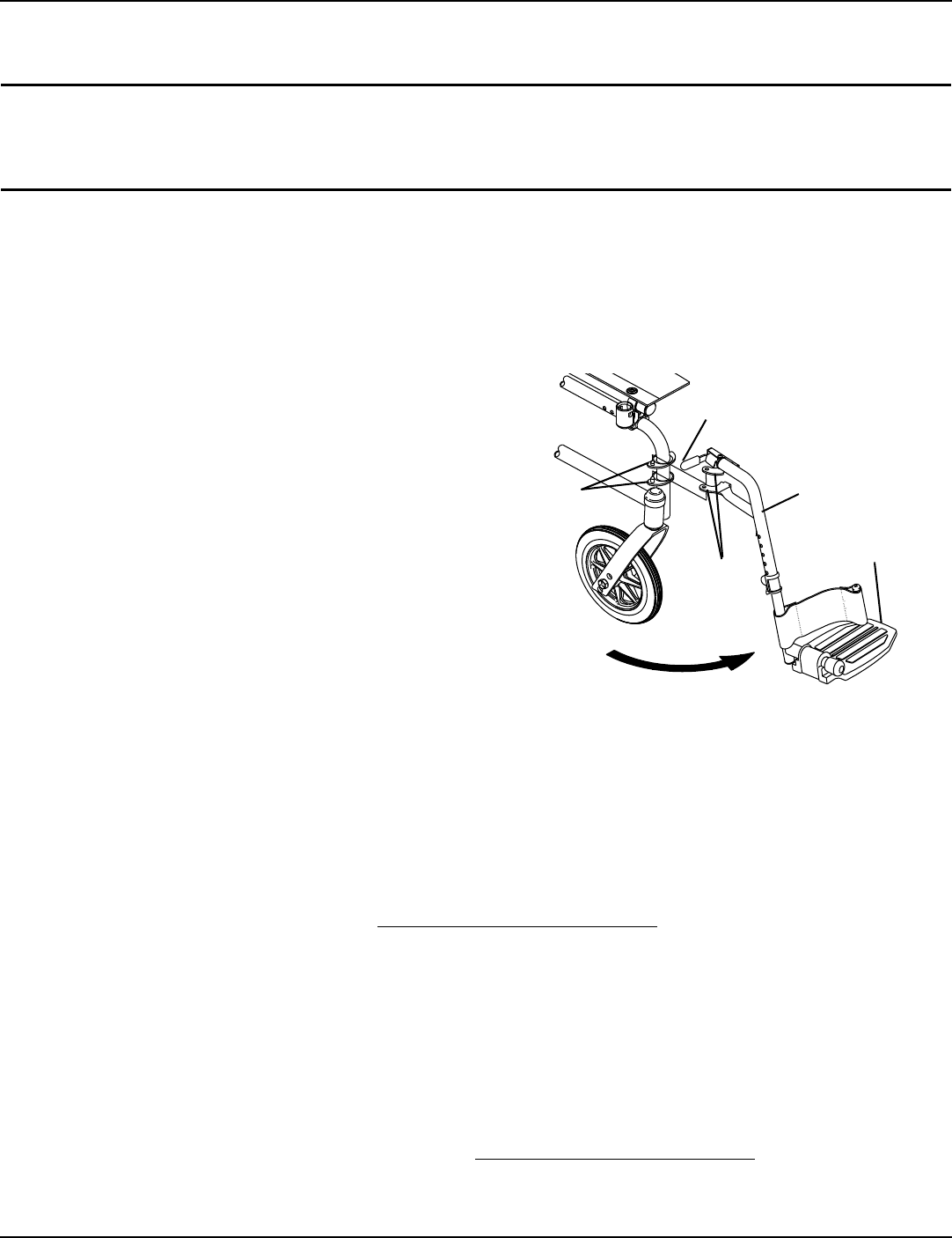
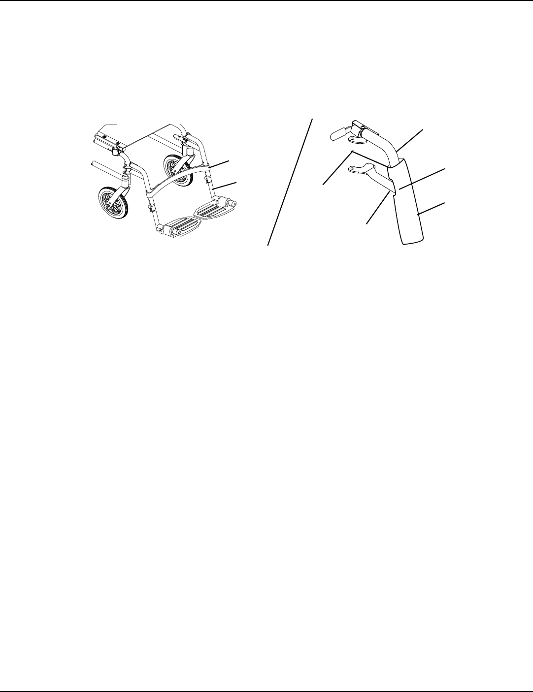
Installing/Removing Front Riggings
NOTE:Forthisprocedure,refertoFIGURE 4.1.
Installing
1. Turnthefrontriggingassemblytotheside(openfront
riggingisperpendiculartowheelchair).
2. Installthehingeplatesonthefrontriggingassembly
ontothehingepinsonthewheelchairframe.
3. Pushthefrontriggingassemblytowardstheinsideof
thewheelchairuntilitlocksintoplace.
NOTE:Thefootplatewillbeontheinsideofthewheelchairwhen
lockedinplace.
4. Repeatthisprocedurefortheotherfrontrigging
assembly.
5. Toreleasethefrontrigging,pushthefrontrigging
releaseleverinward,rotatefrontriggingoutward.
Removing
1. Pushthefrontriggingreleaseleverinward
2. Rotateswingawayfrontriggingassemblyoutward.
3. Lifttheswingawayfrontriggingassemblyoffthehinge
pins. FIGURE 4.1 Installing/Removing Front Riggings
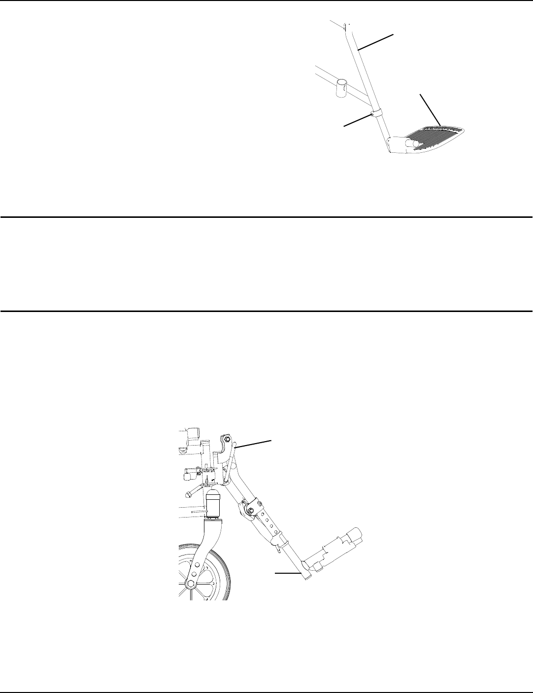
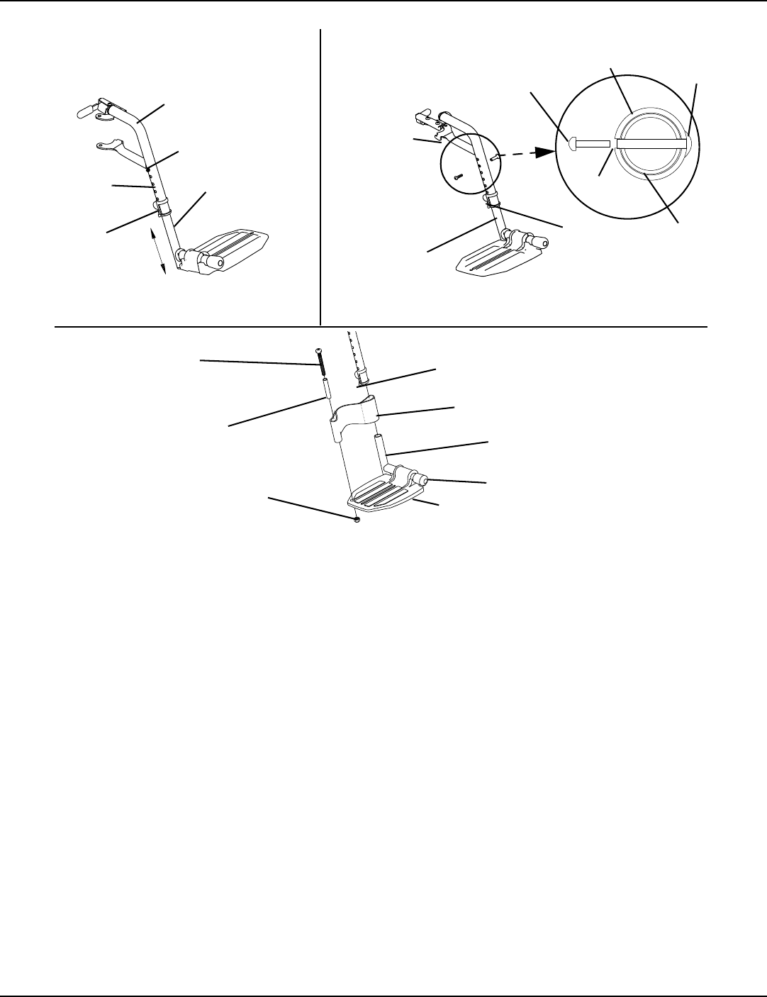
Adjusting Footplate Height
Spring Button
NOTE:Forthisprocedure,refertoFIGURE 4.2.
NOTE:Thisprocedureappliestotheswingawayfrontriggingsandswingawayelevatinglegrest.
1. Removethefrontriggingassembly.RefertoInstalling/RemovingFrontRiggingsonpage 19.
NOTE:Laythefrontriggingassemblyonaflatsurfacetosimplifythisprocedure.
2. Pullthecamlockleveruptounlockedposition.
NOTE:Theelevatinglegresthastwosetsofreleasebuttons,onesetabovetheother.Eachsetwillbevisibleoneatatimeallowingfiner
footplateheightadjustment.
3. Pushinthereleasebuttonsandrepositionthefootplateassemblytothedesiredheight.
4. Ensurethatthereleasebuttonsfullyprotrudefromholesonbothsidesofthefrontriggingsupport.
5. Rotatecamlockleverdowntolockedposition.
6. Repeatthisprocedurefortheotherfootplate,ifnecessary.
7. Reinstalltheswingawayfrontriggingassembly.RefertoInstalling/RemovingFrontRiggingsonpage 19.
Front Rigging
Release Lever
Front Rigging
Assembly
Footplate
Hinge
Plates
Hinge
Pins
NOTE:Swingawayfootrestshown.
SECTION 4—FRONT RIGGINGS
Tracer® EX2 20 Part No. 1110546
FIGURE 4.2 Spring Button
Bolt-In-Place
NOTE:Forthisprocedure,refertoFIGURE 4.3onpage20.
NOTE:Thisprocedureappliestotheswingawayfootrestsandswingawayelevatinglegrest.
1. Removetheswingawayfrontrigging.RefertoInstalling/RemovingFrontRiggingsonpage 19.
NOTE:Laythefrontriggingassemblyonaflatsurfacetosimplifythisprocedure.
2. Pullthecamlockleveruptotheunlockedposition.
3. Usingascrewdrivertoholdthethreadedrivetinposition,removethebuttonheadscrewfromthethreadedrivet.
4. Removethethreadedrivetandbuttonheadscrewsecuringthefootplateassemblytothefrontriggingsupport.
5. Adjustthefootplateassemblyheightbyaligningthedesiredadjustmentholesintheupperfrontriggingsupportand
lowerfootplateassembly.
6. Fromtheoutsideoftheswingawayfrontrigging,insertthethreadedrivetthroughboththefrontriggingsupportand
thefootplateassembly.
7. Fromtheinsideoftheswingawayfrontrigging,insertthebuttonheadscrewthroughtheappropriateadjustmenthole
andthreadintothethreadedrivet.
8. Usingascrewdrivertoholdthethreadedrivetinposition,securelytightenthebuttonheadscrew.Torqueto32in‐lbs.
9. Rotatecamlockleverdowntolockedposition.
10. RepeatSTEPS1‐9toadjusttheremainingfootrest.
FIGURE 4.3 Bolt-In-Place
Front Rigging Support
Release Button
Footplate
Assembly
Cam Lock Lever
Adjustment
Holes
NOTE:Swingawayfootrestshown.
Front Rigging
Support
Button Head
Screw
Threaded Rivet
Footplate
Assembly
NOTE:Swingawayfootrestshown.
Footplate
Assembly
Threaded
Rivet
Front Rigging
Support
Button Head
Screw
Adjustment
Hole
Inside of
Swingaway
Front Rigging
Adjustment
Hole
Cam Lock
Lever
Outside of
Swingaway
Front Rigging
SECTION 4—FRONT RIGGINGS
Part No. 1110546 21 Tracer® EX2
Fixed Frame
NOTE:Forthisprocedure,refertoFIGURE 4.4
1. Removeimpactguardsand/orcalfstrap,ifnecessary.
2. Loosen,butdonotremovetheboltandlocknutthat
securethelowerfootrestassemblytotheupperfootrest
support.
3. Repositionthelowerfootrestassemblytothedesired
height.
4. Securelytightentheboltandlocknut.
5. Repeatthisprocedurefortheotherfootrest,if
necessary.
6. Replaceimpactguardsand/orcalfstrap,ifnecessary. FIGURE 4.4 Fixed Frame
Raising/Lowering Elevating Legrest Assembly
WARNING
Ensure hands and fingers are clear of elevating legrest mechanism before pushing release lever
to lower the elevating legrest. Otherwise injury may occur due to pinch points.
The wheelchair user’s leg MUST be supported by an assistant before attempting to lower
legrest.
NOTE:Forthisprocedure,refertoFIGURE 4.5.
1. Toraisetheelevatinglegrest,theassistantshouldholdthesupporttubeandraisetheelevatinglegrestuntilthedesired
heightisobtained.
2. Tolowertheelevatinglegrest,performthefollowing:
A. Supportuserlegwithonehand.
B. Pushreleaseleverdownwardwithotherhand.
C. Gently,loweruserlegdownandrestagainstthelegrest.
FIGURE 4.5 Raising/Lowering Elevating Legrest Assembly
Bolt and
Locknut
Wheelchair Frame
Footplate
Assembly
Release Lever
Support
Tube
SECTION 4—FRONT RIGGINGS
Tracer® EX2 22 Part No. 1110546
Installing Impact Guards/Calf Strap
NOTE:Forthisprocedure,refertoFIGURE 4.6.
1. Removeimpactguard/calfstrapfrompackagedcontainerifnotalreadysecuredtothefootrest.
2. Secureoneimpactguardtotheeachfootrest.
NOTE:Ensuretheupperportionoftheimpactguardisbetweenthetwohorizontalsupportsofthefootrest.
3. Secureonesideofthecalfstraparoundeachfootrest(withtheimpactguardsattached,ifpresent).
FIGURE 4.6 Installing Impact Guards/Calf Strap
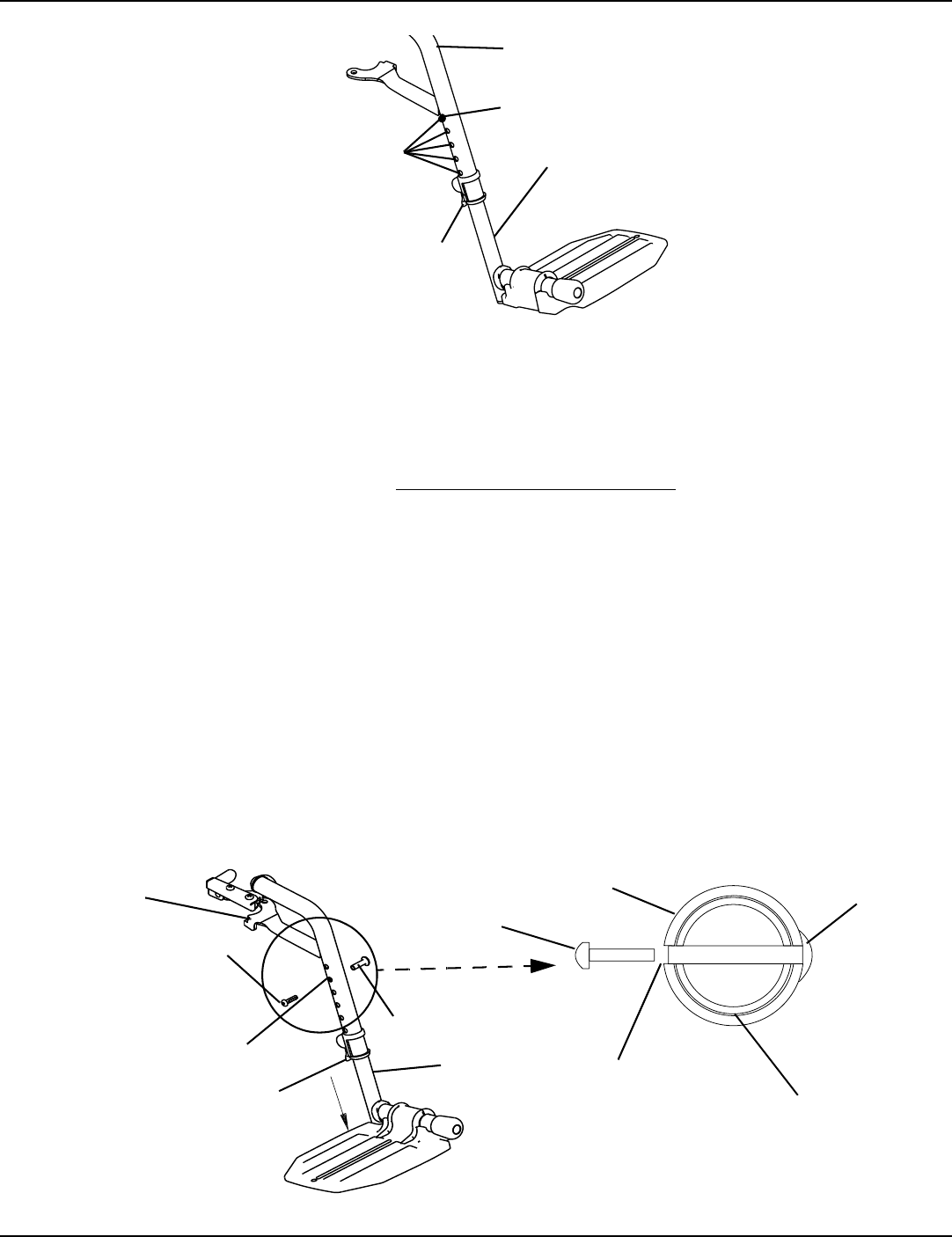
Replacing Heel Loop
NOTE:Forthisprocedure,refertoFIGURE 4.7onpage23.
1. Pullthecamlockleveruptounlockedposition.
2. PerformoneofthefollowingasshowninDetailʺAʺ.
• FootplateswithSpringButtons:
i. Pushinthereleasebuttonsandremovethefootplateassemblyfromthefrontriggingsupport.
•Bolt‐In‐PlaceFootplates:
i. Usingascrewdrivertoholdthethreadedrivetinposition,removethebuttonheadscrewfromthethreaded
rivet.
ii. Removethethreadedrivetandbuttonheadscrewsecuringthefootplateassemblytothefrontriggingsupport.
3. Removethemountingscrew,spacerandlocknutthatsecuretheheellooptothefootplate.
4. Removeexistingheelloopfromslidetube.
5. Installnewheelloopontoslidetube.
6. Installthemountingscrew,spacerandlocknuttosecuretheheellooptothefootplate.Tightenuntilthespacerissecure.
7. Insertthelowerfootrestassemblyintotheupperfootrestassemblytodesiredheight.
8. PerformoneofthefollowingasshowninDetailʺAʺ:
• FootplatesWithSpringButtons:
i. Ensurethatthereleasebuttonsfullyprotrudefromholesonbothsidesoftheupperfootrestsupport.
•Bolt‐In‐PlaceFootplates:
i. Fromtheoutsideoftheswingawayfrontrigging,insertthethreadedrivetthroughboththefrontrigging
supportandthefootplateassembly.
ii. Fromtheinsideoftheswingawayfrontrigging,insertthebuttonheadscrewthroughtheappropriate
adjustmentholeandthreadintothethreadedrivet.
iii. Usingascrewdrivertoholdthethreadedrivetinposition,securelytightenthebuttonheadscrew.Torqueto32
in‐lbs.
9. Rotatecamlockleverdowntolockedposition.
Calf Strap
Footrest
Horizontal Support
Upper Portion of
Impact Guard Impact
Guard
Notch
Horizontal
Support
SECTION 4—FRONT RIGGINGS
Part No. 1110546 23 Tracer® EX2
FIGURE 4.7 Replacing Heel Loop
NOTE:Swingawayfootrestshown.
Adjustment
Holes
Cam Lock
Lever
Footplate
Assembly
Release Button
Front Rigging
Support
DETAIL “A” Footplates with
Spring Buttons
Bolt-in-Place
Footplates
Inside of
Swingaway Front
Rigging
Outside of Swingaway
Front Rigging
Footplate
Assembly
Adjustment
Hole
Cam Lock
Lever
Footplate
Assembly
Front Rigging
Support
Button Head
Screw
Threaded
Rivet
Front Rigging
Support
NOTE:Swingawayfootrest
shown.
Cam Lock
Lever
Heel Loop
Slide Tube
Footplate Assembly
Spacer
Locknut
Mounting
Screw
Footplate
SECTION 5—ARMS
Tracer® EX2 24 Part No. 1110546
SECTION 5—ARMS
WARNING
After any adjustments, repair or service and before use, make sure all attaching hardware is
tightened securely. Otherwise injury or damage may occur.
Adjusting Armrest Height
WARNING
Make sure the height adjustment lever is in the locked position before using the wheelchair.
NOTE:Forthisprocedure,refertoFIGURE 5.1.
1. Unlockthearmrestbyflippingtheheightadjustmentleveronthetopfrontofthearmresttotheup(horizontal)position.
2. Adjustarmresttooneoffivepositions.
NOTE:HeightadjustmentleverMUSTbeintheunlockedpositionwhenplacingarmrestintothearmassembly.
NOTE:Lockthearmrestbypressingtheheightadjustmentleverintothedown(vertical)positionwhenthedesiredarmrestheightis
achieved.
NOTE:RepeatSTEPS1‐3forotherarmrest.
FIGURE 5.1 Adjusting Armrest Height
Locked
(Vertical)
Unlocked (Horizontal)
Armrest Height
Adjustment
Lever
SECTION 5—ARMS
Part No. 1110546 25 Tracer® EX2
Removing/Installing Armrests
WARNING
Make sure the armrest release lever is in the locked position before using the wheelchair.
NOTE:Forthisprocedure,refertoFIGURE 5.2onpage25.
Removing Armrest
1. Pushdownonarmresttoensureitisfullyseatedinfrontandrearsockets.
NOTE:STEP1preventsthereleasebuttonsfromhanginguponthesocketsduringremoval.
2. Pressinthearmrestreleasebuttonatthefrontandrearofthearmrest.
3. Whilepressinginthearmrestreleasebuttons,removethearmrestfromthearmsocketsbypullingstraightup.
Installing Armrest
1. Positionthearmrestjustabovethefrontandreararmsockets.
2. Pusharmdownevenlyatthefrontandrearuntilthefrontandreararmrestreleasebuttosnsnapintothearmsockets.
3. Ensurearmrestislockedsecurelyinthearmsocketsbygentlyliftingup.Ifnotlocked,repeatSTEPS1‐3.
FIGURE 5.2 Removing/Installing Armrests
Armrest Release
Button
Armrest
Rear Arm
Socket
Front Arm
Socket
Armrest Release
Button
SECTION 6—SEAT AND BACK
Tracer® EX2 26 Part No. 1110546
SECTION 6—SEAT AND BACK
WARNING
After any adjustments, repair or service and before use, make sure all attaching hardware is
tightened securely. Otherwise injury or damage may occur.
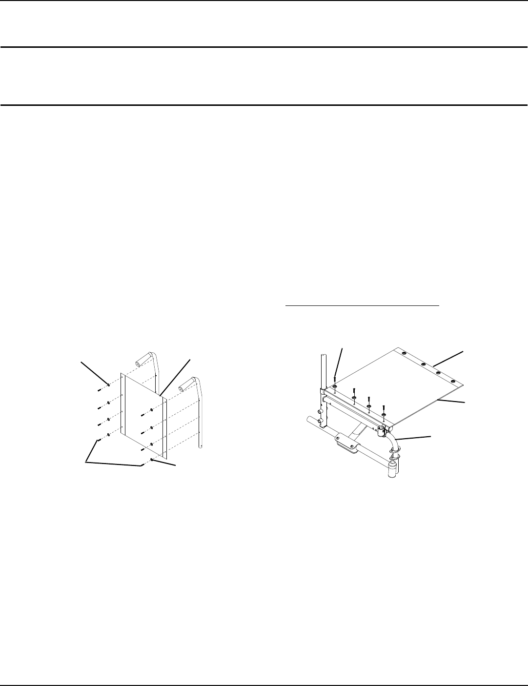
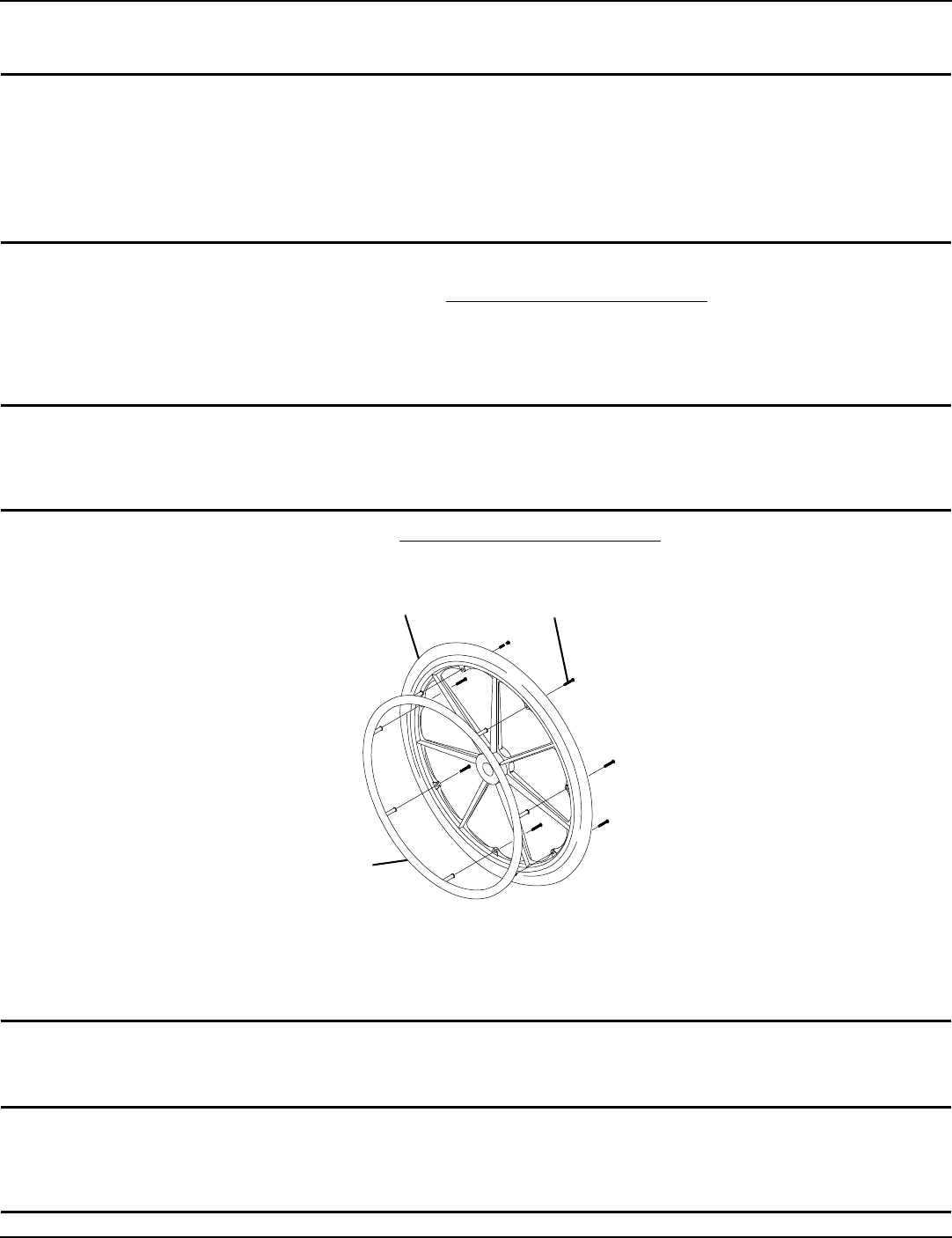
Replacing Back Upholstery
NOTE:Forthisprocedure,refertoForthisprocedure,refertoFIGURE 6.1.
1. Removetheeightmountingscrewsandwashersthatsecuretheexistingbackupholsterytothebackcanes.
2. Removeexistingbackupholsteryfromthebackcanes.
3. Securelytightenthenewbackupholsterytothebackcaneswiththephillipsscrewsandwashers.Thefollowingchart
determinesthenumberofmountingscrewsforeachseatdepth.
Replacing Seat Upholstery
NOTE:Forthisprocedure,refertoFIGURE 6.4.
1. Removetheeightphillipsscrewsandwashersthatsecuretheexistingseatupholsterytothecrossbraces.
2. Removetheexistingseatupholsteryfromthecrossbraces.
3. Ensurepositioningofseatpositioningstrap(ifused).RefertoInstallingtheSeatPositioningStraponpage 39.
4. InstallnewseatupholsterybyreversingSTEPS1‐2.
FIGURE 6.1 Replacing Back/Seat Upholstery
Washers Back Upholstery
Washers
Mounting
Screws
Mounting Screws
Wheelchair
Frame
Seat
Upholstery
16-inch Seat
Depth
SECTION 6—SEAT AND BACK
Part No. 1110546 27 Tracer® EX2
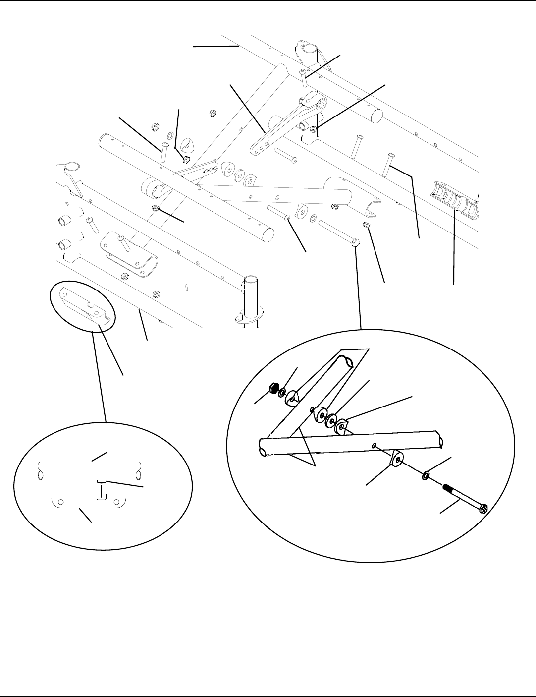
Adjusting the Seat Width
Swingaway Front Riggings
NOTE:FIGURE 6.2onpage27andFIGURE 6.3onpage28.
NOTE:Whenadjustingtheseatwidthofthewheelchair,thebackandseatupholsteryMUSTbechanged.Ifapplicable,theheadrest
pillowandheadrestupholsteryMUSTbechangedaswell.
1. Removetheexistingbackandseatupholsteryfromthewheelchair.RefertoReplacingBackUpholsteryonpage 26and
ReplacingSeatUpholsteryonpage 26.
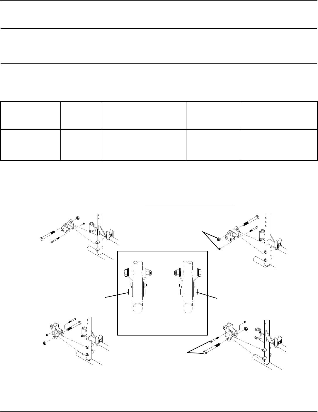
2. Removethefourbuttonscrewsandlocknutsthatsecurethetwopivotlinkstothewheelchairframeandcrossbraces.
3. Removethetwobuttonscrews,locknutsandcrossbracesaddlethatsecuresthebottomofthecrossbracetothe
wheelchairframe.Repeatforothercrossbrace.
4. Removethehexscrew,covedwashers,washersandlocknutthatsecurethetwocrossbracestogether.SeeDetailʺBʺ.
FIGURE 6.2 Adjusting the Seat Width - Swingaway Front Riggings
NOTE:Notetheorientationofthecovedwashers,washersandlocknutforassemblingthenewcrossbraces.SeeDetailʺBʺ.
5. Assemblethetwonewcrossbracestogetherwiththeexistinghexscrew,covedwashers,washersandlocknut.Securely
tighten.RefertoDetailʺBʺforhardwareorientation.
6. Determinethecorrectpivotlinkandmountingholetousewiththedesiredseatwidth.Seechartbelow.
7. Securethepivotlinkstothecrossbracesandwheelchairframewiththefourbuttonscrewsandlocknuts.Securely
tighten.
NOTE:Positioncrossbracesaddleonwheelchairframeusingthewasherontheundersideofthewheelchairframeasareference.See
DetailʺAʺforproperpositioningofthecrossbracesaddle.
8. Reinstallthetwobuttonscrews,locknutsandcrossbracesaddlethatsecuresthebottomofthenewcrossbracetothe
wheelchairframe.RefertoDetailʺBʺforhardwareorientation.Repeatforoppositecrossbrace.Securelytighten.
9. Installthenewbackandseatupholsteryontothewheelchair.RefertoReplacingBackUpholsteryonpage 26and
ReplacingSeatUpholsteryonpage 26.
SEAT WIDTH PIVOT LINK
16 - INCH
18 - INCH
20 - INCH
22 - INCH
I
16-inch 18-inch
DO NOT USE
DO NOT USE
20-inch
SECTION 6—SEAT AND BACK
Tracer® EX2 28 Part No. 1110546
FIGURE 6.3 Adjusting the Seat Width - Swingaway Front Riggings
Pivot Lock
(STEPS 2,7)
Crossbrace
(STEPS 4,5)
Button Screw
(STEPS 2,7)
Locknut (STEPS
2,7)
Wheelchair Frame
Locknut
(STEPS 2,7)
Locknut
(STEPS 3,8)
Button
Screw
(STEPS 3,8)
Crossbrace
Saddle (STEPS
3,8)
Locknut
(STEPS 2,7)
Button Screw
(STEPS 2,7)
Button Screw
(STEPS 2,7)
Crossbrace
Saddle (STEPS
3,8)
DETAIL “B” - CROSSBRACE
HARDWARE (STEPS 4,5)
Crossbrace
Saddle
Washer
Wheelchair
Frame
DETAIL “A” Locknut
Washer
Coved
Washers
Washer
Coved
Washer
Crossbraces
Coved
Washers
Washer
Hex Screw
SECTION 6—SEAT AND BACK
Part No. 1110546 29 Tracer® EX2
Fixed Frame
NOTE:Forthisprocedure,refertoFIGURE 6.4.
Removing Lower Mounting Hardware
1. Removetheexistingbackandseatupholsteryfromthewheelchair.RefertoReplacingBackUpholsteryonpage 26and
ReplacingSeatUpholsteryonpage 26.
NOTE:Ifadjustingtheseatwidthofthewheelchair,backandseatupholsteryaswellasthecrossbracesMUSTbereplaced.
2. Removethefourscrewsandlocknutsthatsecuretheinserttubetothelowerwheelchairframe.
3. Removetheinsertsfromtherearofthewheelchair.
4. Removethehexscrewandlocknutthatsecurethetwoexistingcrossbracestogether.
Removing Upper Mounting Hardware
1. Whilepushingdownontherearseatguide,pullupthefrontseatguideuntilthefrontseatguidereleasesfromthe
wheelchairframe.
2. Pullthecrossbraceawayfromtherearseatguide.
3. RepeatSTEPS1‐2foroppositecrossbrace.
4. ReverseSTEPS1‐3toassembletheuppermountinghardware.
5. ReverseSTEPS1‐4inRemovingLowerMountingHardwareonpage 29.
FIGURE 6.4 Adjusting the Seat Width - Fixed Frame
DETAIL “B” -
REMOVING UPPER
MOUNTING
HARDWARE
DETAIL “A” - REMOVING LOWER
MOUNTING HARDWARE
Rear Seat Guide
Crossbrace
Front Seat Guide
Crossbrace
Insert Tube
Wheelchair Frame
Locknut
Screw
Hex Screw
SECTION 7—REAR WHEELS
Tracer® EX2 30 Part No. 1110546
SECTION 7—REAR WHEELS
WARNING
After any adjustments, repair or service and before use, make sure all attaching hardware is
tightened securely. Otherwise injury or damage may occur.
Removing/Installing Rear Wheels
WARNING
Only a qualified technician may change the size of the rear wheel or the seat-to-floor height.
If changing the size of the rear wheel or a change in the Seat-to-Floor Height is desired, this
procedure MUST be performed by a qualified technician.
Make sure both rear wheels are the same size and are installed into the same respective mounting
hole BEFORE using the wheelchair, otherwise injury may occur.
Permanent Axles
WARNING
This procedure MUST be performed by a qualified technician.
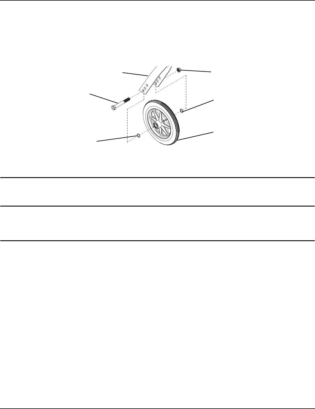
NOTE:Forthisprocedure,refertoFIGURE 7.1.
NOTE:Ifreplacingthesamesizerearwheel,notethemountingpositiononthewheelchairframeforproperreinstallationofthenewrear
wheel.
1. Removethedustcap(SAFrameonly),hexscrew,washer(SAFrameonly),spacer(ifinstalled)andlocknutthatsecure
therearwheeltothewheelchairframe.
NOTE:Thespacerisusedonwheelchairswithremovablearmsonly.
2. RepeatSTEP1fortheoppositerearwheelifdesired.
3. Toreinstalltherearwheel(s)ontothewheelchair,reverseSTEPS1‐2andtorquelocknutto40ft.‐lbs.
4. Adjustwheellocks.RefertoUsing/AdjustingPatientOperatedWheelLocksonpage 35.
FIGURE 7.1 Removing/Installing Rear Wheels - Permanent Axles
Rear Wheel
Washer
(SA Frame
ONLY)
Dust Cap
(SA Frame
ONLY) Hex
Screw
Spacer (Wheelchairs
with Removable
Arms ONLY)
Wheelchair
Frame
Locknut
Axle Mounting
Axle
SECTION 7—REAR WHEELS
Part No. 1110546 31 Tracer® EX2
Replacing Rear Wheel Handrim
WARNING
Wheelchairs with 300 lbs weight limit: DO NOT use composite handrims. Otherwise injury or
damage may occur.
If the wheelchair is equipped with permanent axles, this procedure MUST be performed by a
qualified technician.
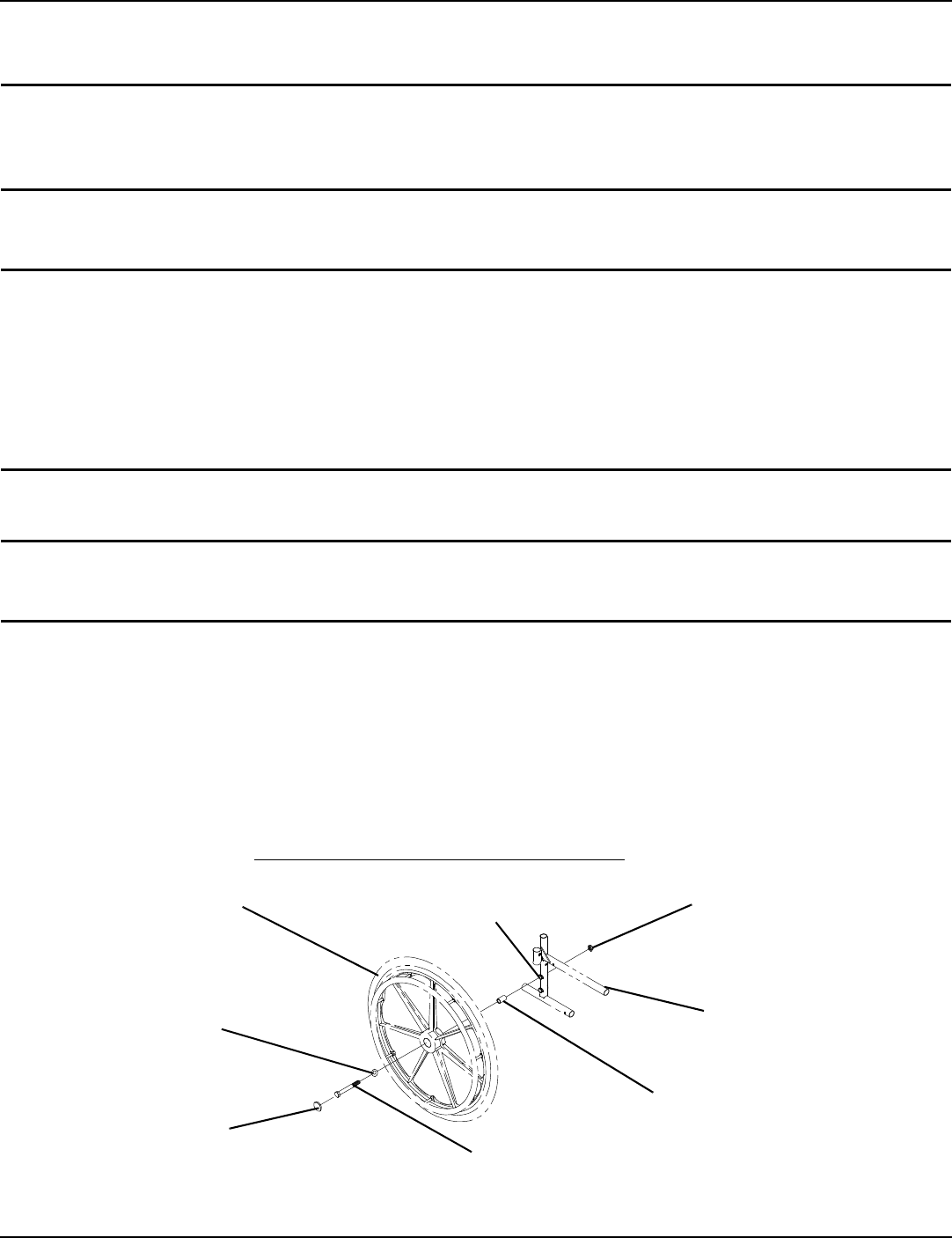
NOTE:Forthisprocedure,refertoFIGURE 7.2.
1. Removetherearwheelfromthewheelchair.RefertoRemoving/InstallingRearWheelsonpage 30.
2. Removethemountingscrewsthatsecurethehandrimtotherearwheel.
3. Removetheexistinghandrim.
4. Installthenewhandrimbyreversingtheprecedingsteps.
WARNING
Make sure detent pin and detent balls of the quick-release axles are fully released before operat-
ing the wheelchair.
5. Reinstallrearwheeltothewheelchair.RefertoRemoving/InstallingRearWheelsonpage 30.
6. RepeatSTEPS1‐5fortheoppositerearwheelifnecessary.
FIGURE 7.2 Replacing Rear Wheel Handrim
Replacing/Repairing Rear Wheel Tire
WARNING
Replacement of rear wheel tire MUST be performed by a qualified technician.
CAUTION
As with any vehicle, the wheels and tires should be checked periodically for cracks and wear, and
should be replaced if damaged.
Mounting Screw
Rear Wheel
Handrim
SECTION 8—FRONT CASTERS
Tracer® EX2 32 Part No. 1110546
SECTION 8—FRONT CASTERS
WARNING
After any adjustments, repair or service and before use, make sure all attaching hardware is
tightened securely. Otherwise injury or damage may occur.
Installing/Replacing Six or Eight-Inch Front Casters and Forks
WARNING
Make sure both fork/caster assemblies are the same size BEFORE using the wheelchair, other-
wise injury may occur.
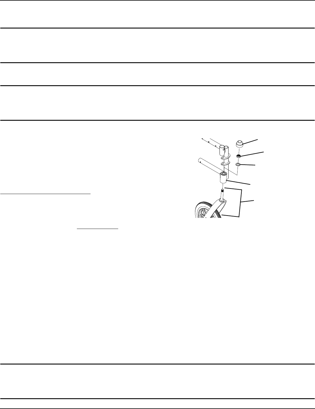
NOTE:Forthisprocedure,refertoFIGURE 8.1.
NOTE:Thisprocedurecanbeperformedifreplacingtheexact
samesizefrontcaster.
1. Removethedustcover.
2. Removethelocknutandnylonwasherthatsecuresthe
forktothecasterheadtube.
3. Droptheforkassemblyoutofthecasterheadtube.
NOTE:Ifcasterreplacementisdesired,referto
Replacing/RepairingFrontCasterTireonpage 33.
4. Slidethenewforkassemblyintothecasterheadtube.
5. ReassemblebyreversingSTEPS1‐3.
6. RepeatSTEPS1‐6fortheoppositeforkassembly.
7. Adjusttheforks.RefertoAdjustingForksonpage 32. FIGURE 8.1 Installing/Replacing Six or Eight-Inch Front
Casters and Forks
Adjusting Forks
1. Toproperlytightencasterjournalsystemandguardagainstflutter,performthefollowingcheck:
A. Tipbackofwheelchairtofloor.
B. Pivotbothforksandcasterstotopoftheirarcsimultaneously.
C. Letcastersdroptobottomofarc(wheelsshouldswingoncetoone‐side,thenIMMEDIATELYrestinastraightdownward
position).
D. Adjustlocknutsaccordingtofreedomofcasterswing.
E. RepeatSTEPSC‐Duntilwheelsswingoncetoone‐side,thenIMMEDIATELYrestinadownwardposition.
2. Testwheelchairformaneuverability.
3. Readjustlocknutsifnecessary,andrepeatSTEPS1‐2untilcorrect.
4. Snapdustcoveroverthelocknutandstem.
Replacing Front Casters
WARNING
Make sure both front casters are the same size and are installed into the same respective mount-
ing hole before using the wheelchair, otherwise injury may occur.
Dust Cover
Locknut
Nylon Washer
Caster Headtube
Fork Assembly
SECTION 8—FRONT CASTERS
Part No. 1110546 33 Tracer® EX2
NOTE:Forthisprocedure,refertoFIGURE 8.2.
NOTE:Ifreplacingthesamesizefrontcaster,notethemountingpositionontheforkassemblyforproperreinstallationofthenewfront
caster.
1. Removethehexscrew,washersandlocknutthatsecurethefrontcastertothefork.
NOTE:Washersareonlyusedwith6and8‐inchcasterswithprecisionbearings.
2. Toreinstallthenewfrontcasterontothefork,reversestep1.
FIGURE 8.2 Replacing Front Casters
Replacing/Repairing Front Caster Tire
WARNING
Replacement of front caster tire MUST be performed by a qualified technician.
CAUTION
As with any vehicle, the wheels and tires should be checked periodically for cracks and wear, and
should be replaced when necessary.
Locknut
Washer (if applicable)
Front Caster
6 or 8-inch Fork
Hex Screw Washer (if applicable)
SECTION 9—ANTI-TIPPERS/WHEEL LOCKS
Tracer® EX2 34 Part No. 1110546
SECTION 9—ANTI-TIPPERS/WHEEL LOCKS
WARNING
After any adjustments, repair or service and before use, make sure all attaching hardware is
tightened securely. Otherwise injury or damage may occur.
Installing/Adjusting Anti-tippers
WARNING
Anti-tippers are specific to the different seat-to-floor heights. Refer to the chart in this section of
the manual for correct usage and adjustment. If these requirements cannot be achieved, DO
NOT use the wheelchair. Contact a qualified technician. If changing the seat-to-floor height, the
correct anti-tippers MUST be used to maintain a 11/2 to 2 inch ground clearance.
If so equipped, anti-tippers MUST be attached at all times. Inasmuch as the anti-tippers are an
option on this wheelchair (You may order with or without the anti-tippers), Invacare strongly
recommends ordering the anti-tippers as a safeguard for the wheelchair user.
Anti-tippers MUST be fully engaged and release buttons fully protruding out of adjustment holes.
ALWAYS use anti-tippers. When outdoors on wet, soft ground or on gravel surfaces, anti tippers
may not provide the same level of protection against tipover. Extra caution MUST be observed
when traversing such surfaces.
Ensure both anti-tippers are adjusted to the same mounting hole.
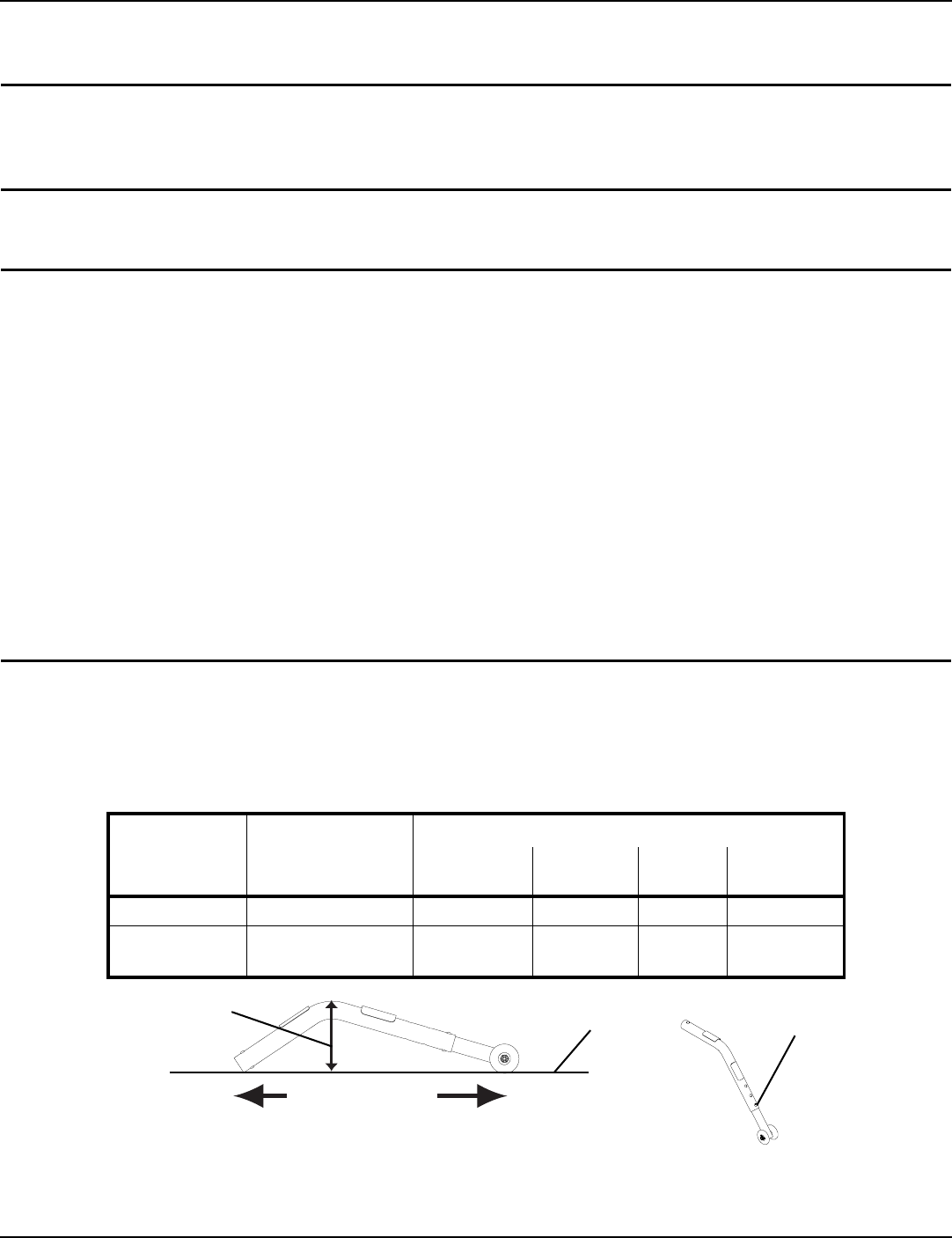
NOTE:Forthisprocedure,refertoFIGURE 9.1onpage34andFIGURE 9.2onpage35.
Installing Anti-Tippers
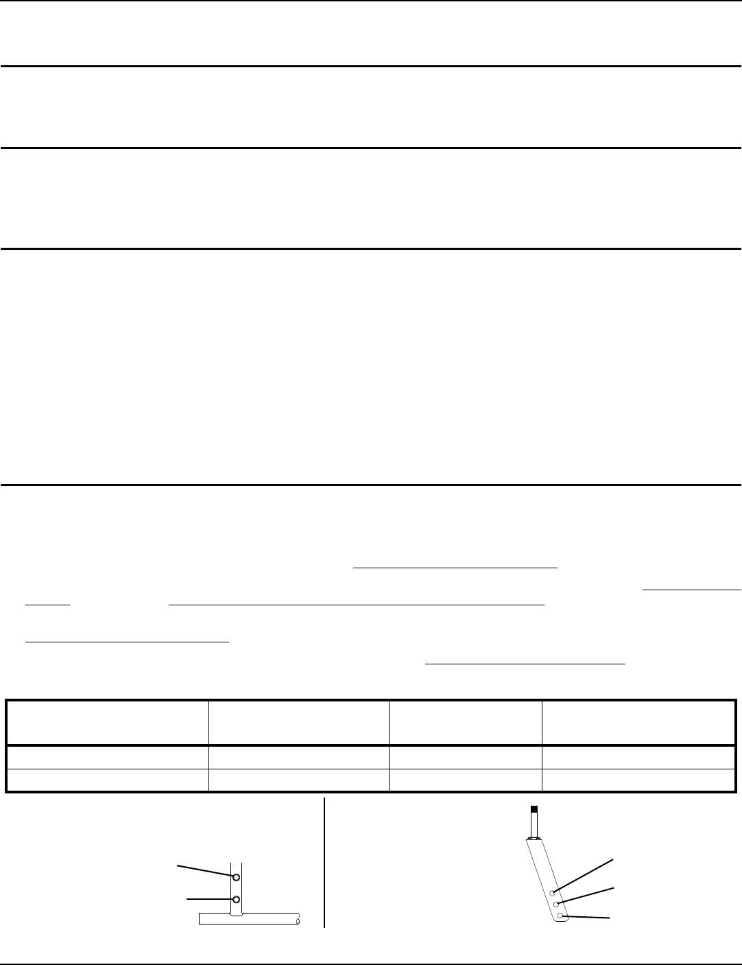
NOTE:Toensurethecorrectmodelanti‐tipperisusedrefertoFIGURE 9.1.Measurementsforanti‐tippersareapproximateandare
takenwithextensiontubeinbottomholeposition.
FIGURE 9.1 Installing/Adjusting Anti-tippers - Anti-Tipper Length
1. Pressthereleasebuttonsandinserttheanti‐tipperswiththeanti‐tipperwheelspointingtowardtheground/floorinto
thewheelchairframetubingasshowninFIGURE 9.2.
WHEEL-
CHAIR
MODEL
SEAT-TO-FLOO
R HEIGHT IN
INCHES
ANTI-TIPPER (MEASUREMENTS IN INCHES)
LENGTH HEIGHT MODEL PART NO.
TRACER EX2 17½ to 19½ 13½ 3¼ 1360 1058836
TRACER EX2
FF 21 12 2¾ 9758 1086190
Anti-Tipper Height
Anti-Tipper Length
Flat Surface Bottom Position
SECTION 9—ANTI-TIPPERS/WHEEL LOCKS
Part No. 1110546 35 Tracer® EX2
2. Ensurethatthereleasebuttonoftheanti‐tipperfullyprotrudesoutoftheholeinthebottomofthewheelchairframe
tubing.
3. Placethewheelchaironaflatsurface.
4. Measurethedistancebetweenthebottomofthe
anti‐tipperwheelsandtheground/floor.
NOTE:A11/2to2inchclearancebetweenthebottomofthe
anti‐tipperwheelsandtheground/floorMUSTbemaintainedat
alltimes.
5. Ifthedistancebetweenthebottomofanti‐tipperwheels
andtheground/floorisnot11/2to2inches,adjust
anti‐tippers.RefertoAdjustingtheAnti‐Tipperson
page 35. FIGURE 9.2 Installing Anti-Tippers
Adjusting the Anti-Tippers
NOTE:Forthisprocedure,refertoFIGURE 9.3onpage35.
NOTE:A1½to2‐inchclearancebetweenthebottomoftheanti‐tipperwheelsandtheground/floorMUSTbemaintainedatalltimes.
1. Placethewheelchaironaflatsurface.
NOTE:Ifadjustinganti‐tippersonreclinermodels,ensurebackcanesareintheuprightpositionbeforemakingadjustments.
2. Pressthereleasebuttonsonthewheeledportionoftheanti‐tipperandslideitupordowntothedesiredadjustment
hole.
3. Checktomakesurethatthereleasebuttonsarefully
engagedinadjustmentholes.
4. Ensurebothanti‐tippersareadjustedtothesame
height.
5. Measurethedistancebetweenthebottomofthe
anti‐tipperwheelsandtheground/floor.
6. Ifthedistancebetweenthebottomofanti‐tipperwheels
andtheground/floorisnot11/2to2inches,repeat
STEPS2‐5untilthedistanceis11/2to2inches.
7. Ifthe11/2to2inchdistancecannotbeachievedwiththe
anti‐tippers,adifferentmodelmayberequired.
ContactanInvacaredealerorqualifiedtechnician. FIGURE 9.3 Adjusting the Anti-Tippers
Using/Adjusting Patient Operated Wheel Locks
Using Patient Operated Wheel Locks
WARNING
DO NOT attempt to stop a moving wheelchair with wheel locks. Wheel locks are not brakes.
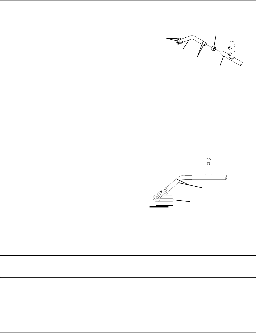
NOTE:Forthisprocedure,refertoFIGURE 9.4onpage36.
NOTE:Positionwheelchaironaflat,levelsurfacetoperformthisprocedure.
NOTE:Ensurethewheelchairisnotmovingbeforeengagingthewheellocks.
1. Performoneofthefollowing:
•Push‐to‐Lock‐Toengage,pushthewheellockhandleforward.
•Pull‐to‐Lock‐Toengage,pullthewheellockhandlebackward.
2. DisengagethewheellocksbyreversingSTEP2.
Anti-Tipper
Wheels
Anti-Tipper
Release Buttons
Rear Frame
Tubing
Anti-Rattle
Release Buttons
11/2 to 2 inch Clearance
SECTION 9—ANTI-TIPPERS/WHEEL LOCKS
Tracer® EX2 36 Part No. 1110546
FIGURE 9.4 Using Patient Operated Wheel Locks
Adjusting Patient Operated Wheel Locks
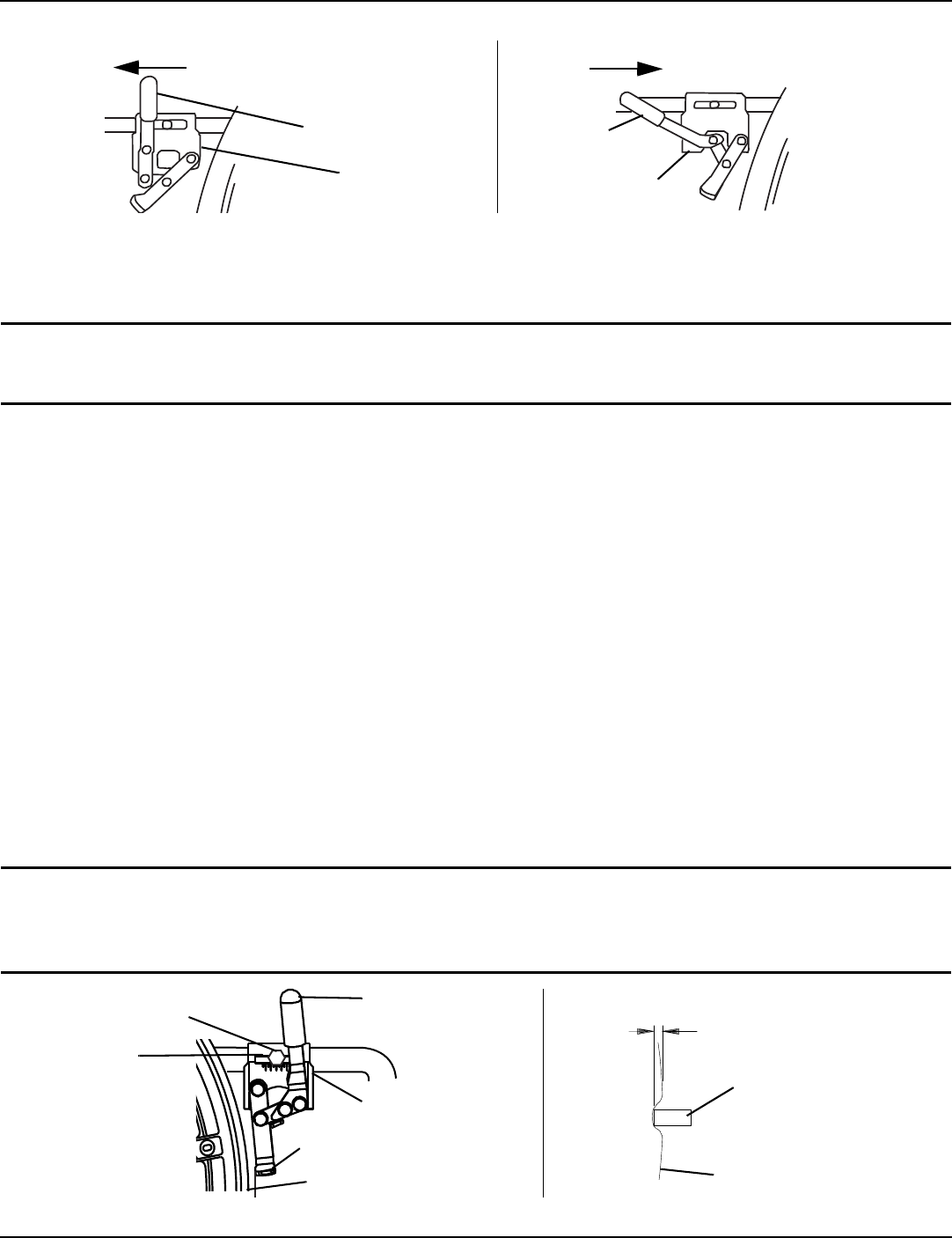
NOTE:Forthisprocedure,refertoFIGURE 9.5.
WARNING
DO NOT attempt to stop a moving wheelchair with the wheel locks. Wheel locks are not brakes.
NOTE:Ifwheelsarepneumatic,beforeadjustingthewheellockassemblies,ensurethatthetiresareinflatedtotherecommendedpsion
thesidewalloftire.
1. Disengagethewheellocks.
2. Loosentheboltandlocknutthatsecurethewheellocktothewheelchairframe.
3. Repositionthewheellocksothatwhen
engaged,thewheellockshoeembedsthetire11/8inch(inchforpneumatictires)andholds
theoccupiedwheelchairinplacewhenpushed.
4. Securelytightentheboltandlocknutattachingthewheellocktothewheelchairframe.
5. Engagethewheellock.
6. MeasurethedistancethewheellockisembeddedintothetireasshowninDetailʺAʺ.
NOTE:Anywheellockadjustmentshouldembedthewheellockshoeatleast
1
/
8
inch(
3
/
16
inchifpneumatictire)intothetirewhenengaged.
7. RepeatSTEPS1‐6untilthewheellockshoeembedsthetire1/8inch(
3
/16inchforothertires)andholdsthewheelchair
inplacewhenpushed.
8. RepeatSTEPS1‐7fortheoppositewheellock.
9. Ifthemeasurementof1/8inch(
3
/16inchforothertires)cannotbeachieved,removetheboltandlocknutthatsecurethe
wheellocktothewheelchairframeandmountthewheellockintheremainingmountingposition.
10. RepeatSTEPS1‐8.
11. Engagebothwheellocksandensuretheoccupiedwheelchairisheldinplacewhenpushed.
WARNING
If wheel locks do not hold the occupied wheelchair in place, contact a qualified technician;
otherwise injury or damage may occur.
FIGURE 9.5 Adjusting Patient Operated Wheel Locks
Push-To-Lock Pull-To-Lock
Unlocked Position
Wheel Lock
Push wheel lock handle forward away
from the tire to engage wheel lock
Pull wheel lock handle backward
toward the tire to engage wheel lock
Unlocked
Position
Wheel Lock
1/8-inch (3/16-inch
pneumatic tires)
Wheel Lock
Shoe
Tire
Wheel Lock
Handle
Rear Wheel
Wheel Lock Shoe
Wheel Lock
Bolt and Locknut
Mounting
Positions
DETAIL “A”
SECTION 10—SEAT TO FLOOR
Part No. 1110546 37 Tracer® EX2
SECTION 10—SEAT TO FLOOR
WARNING
After any adjustments, repair or service and before use, make sure all attaching hardware is
tightened securely. Otherwise injury or damage may occur.
NOTE:Seat‐to‐floorheightisnotadjustableforTracerEX2wheelchairswiththefixedframeoption(FF).ThisprocedureisforEX2
wheelchairswithswingawayfootrestsONLY.
Changing Seat-to-Floor Height
WARNING
The size/position of the front casters, size/position of the rear wheels, use of anti-tipper model, as
well as the user condition directly relate to the stability of the wheelchair. Any change to one or
any combination of the six may cause the wheelchair to decrease in stability. These adjustments
MUST be performed by a qualified technician.
Seat-to-floor heights have specific positions depending on rear wheel size, rear wheel position,
front caster size and front caster position. These adjustments MUST be performed by a qualified
technician.
If changing the seat-to-floor height the correct anti-tippers MUST be ordered to maintain a 1 1/2
to 2 inch ground clearance.
NOTE:Forthisprocedure,refertoFIGURE 10.1onpage37.
1. RefertothefollowingchartinFIGURE 10.1todeterminemountingpositionsforfrontcasters/forksandrearwheelsfor
thedesiredobtainableseat‐to‐floorheight:
2. Removetherearwheelsfromthewheelchair.RefertoRemoving/InstallingRearWheelsonpage 30.
3. Ifnecessary,replacethefrontcastersandforkswiththecastersandforksindicatedinthechart.RefertoReplacingFront
Castersonpage 32andInstalling/ReplacingSixorEight‐InchFrontCastersandForksonpage 32.
4. Reinstalltherearwheelsontothewheelchairinthemountingpositionindicatedinthechart.Referto
Removing/InstallingRearWheelsonpage 30.
5. Adjustanti‐tippersaccordingtonewseat‐to‐floorheight.RefertoInstalling/AdjustingAnti‐tippersonpage 34.
8-INCH FRONT CASTERS
FIGURE 10.1 Changing Seat-to-Floor Height
SEAT-TO-FLOOR HEIGHT
(IN INCHES)
FRONT CASTER
MOUNTING POSITION
REAR WHEEL SIZE REAR WHEEL
MOUNTING POSITION
17½ Top 24 inch Top
19½ Bottom 24 inch Bottom
DETAIL “A” - REAR WHEEL
MOUNTING POSITIONS-
ADULT/HEMI FRAME STYLE
DETAIL “B” - 8 INCH
FORK MOUNTING
POSITIONS
Top
Bottom
Top
Bottom
Middle
SECTION 11—OPTIONS
Tracer® EX2 38 Part No. 1110546
SECTION 11—OPTIONS
WARNING
After any adjustments, repair or service and before use, make sure all attaching hardware is
tightened securely. Otherwise injury or damage may occur.
Installing Amputee Bracket
NOTE:Forthisprocedure,refertoFIGURE 11.1onpage38.
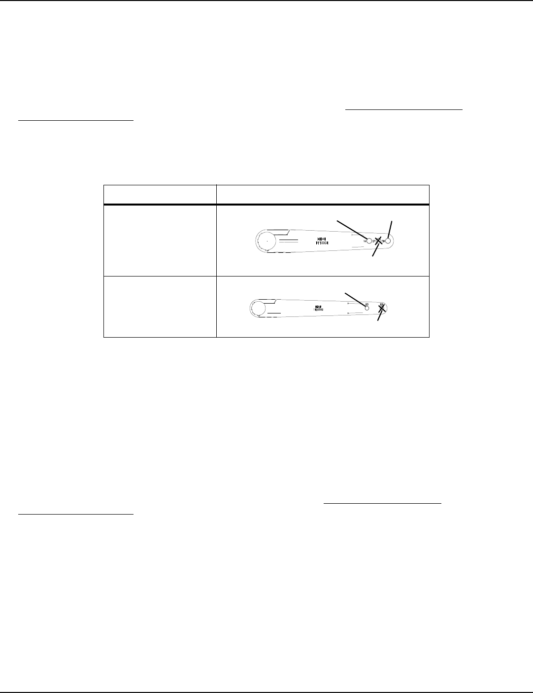
1. RefertothefollowingchartorFIGURE 11.1todeterminethemountingpositionoftheamputeebracket:
*NOTE:ʺAʺandʺBʺarestampedonthesidesoftheamputeebracket.
2. InstalltheamputeebracketonthewheelchairframetothepositiondeterminedinSTEP1.
NOTE:Makesuretheaxlespacerispointingtowardstheoutsideofthewheelchair.
3. Installthetwohexscrewsandlocknutsthatsecuretheamputeebrackettothewheelchair.
4. Installtherearwheelsontothewheelchair.RefertoRemoving/InstallingRearWheelsonpage 30.
FIGURE 11.1 Installing Amputee Bracket
SEAT-TO-FLOOR *BRACKET AXLE SPACER POSITION
(ON BRACKET)
SIDE OF
WHEELCHAIR
AXLE MOUNTING
POSITION
(ON WHEELCHAIR)
ADULT
ADULT
HEMI
HEMI
A
B
B
A
DOWN
DOWN
UP
UP
RIGHT
LEFT
RIGHT
LEFT
TOP
TOP
BOTTOM
BOTTOM
Bracket “A” Bracket “B”
Locknuts
Hemi Right
Hemi Left
Rear View of
Amputee Bracket
Right
Left
Adult Right
Axle Spacer Toward Outside
of Wheelchair
Adult Left
Axle Spacer Toward Outside
of Wheelchair
Hex Screws

SECTION 11—OPTIONS
Part No. 1110546 39 Tracer® EX2
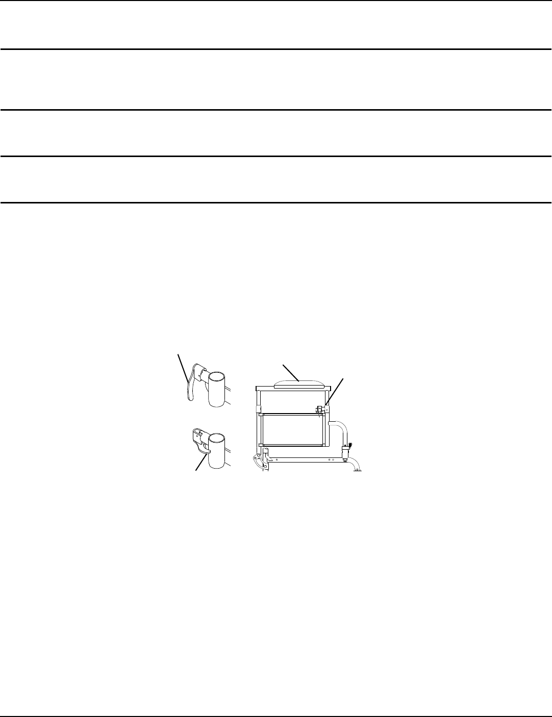
Installing Crutch and Cane Carrier
WARNING
Check base weekly to ensure proper placement.
When loading the crutch/cane carrier, ensure items are securely placed into the base. Also
ensure that there is no interference with folding the wheelchair, the rear wheels, or the
swing-back arms.
Strap MUST be securely fastened while carrying items.
NEVER insert or remove items while wheelchair is moving.
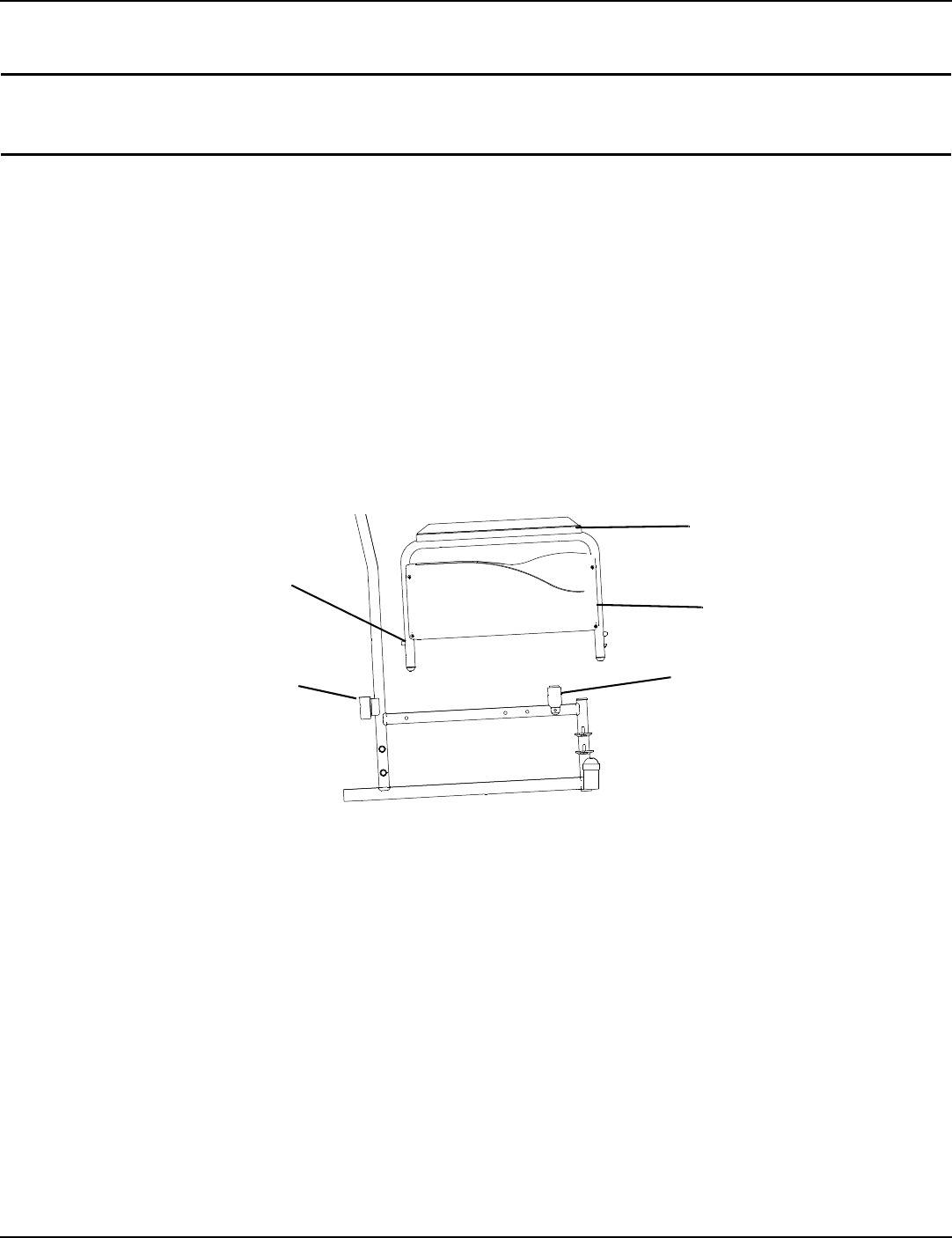
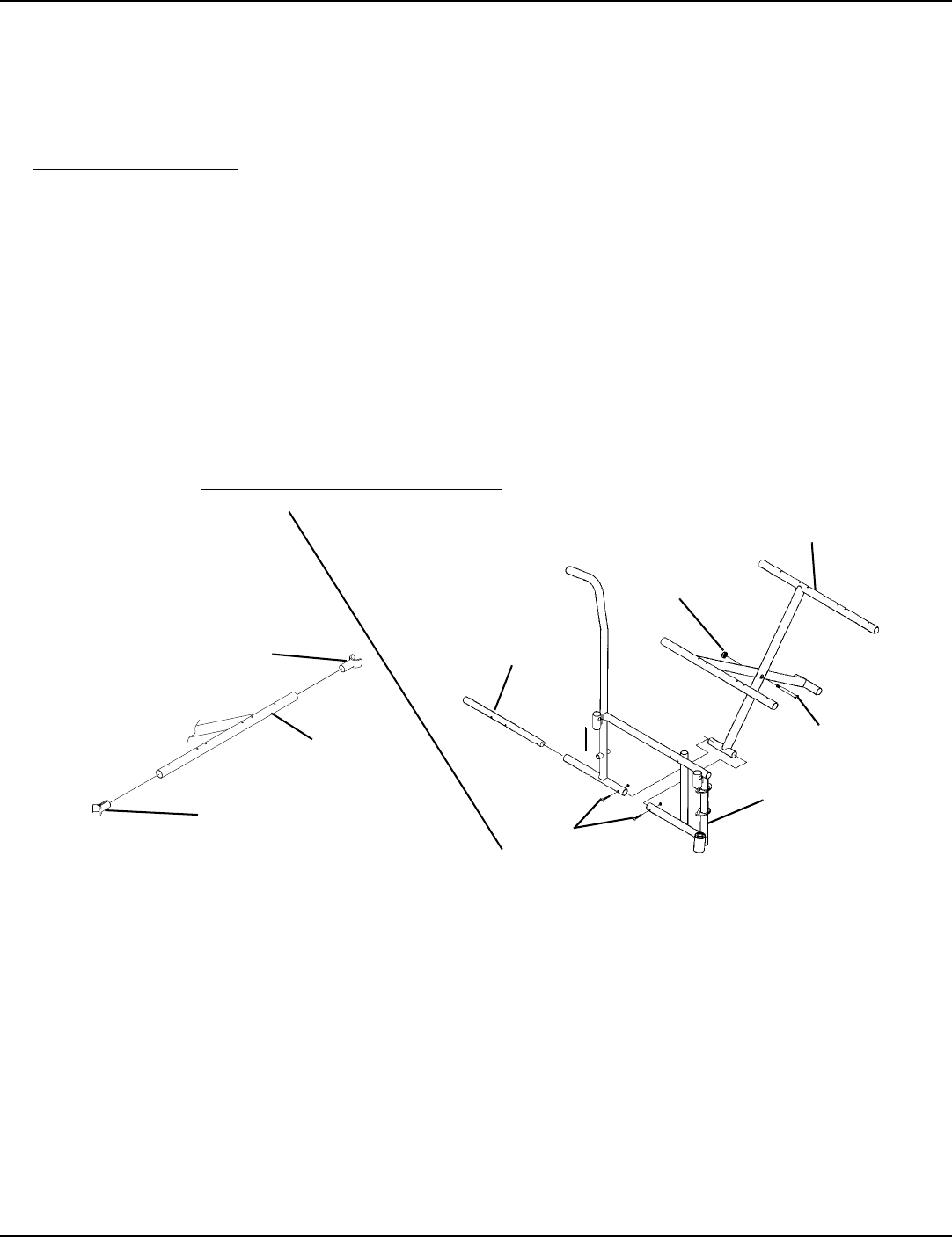
NOTE:Forthisprocedure,refertoFIGURE 11.2.
1. Slidetheclampwiththebaseattachedovertheendofthesteptubeofthewheelchair.Ensurethebaseistowardsthe
insideofthewheelchair.
2. Positionthebaseparalleltothesteptube.
CAUTION
Base should be parallel to step tube to avoid
bending spokes when folding the wheelchair.
3. Securelytightenthelocknutthatsecuresthebasetothe
steptubeofthewheelchair.
4. Removetheupperbackupholsteryscrewandwasher.
5. Alignthestrapwiththebackupholsteryscrew
mountinghole.
6. Reinstallthebackupholsteryscrewandwasherand
securethestraptothewheelchair.
7. Thebasecleanseasilywithanychromeorglasscleaner.
Thestrapcanbecleanedwithmildsoapandwater.
FIGURE 11.2 Installing Crutch and Cane Carrier
Installing the Seat Positioning Strap
WARNING
ALWAYS wear your positioning strap. Inasmuch as the seat positioning strap is an option on this wheel-
chair (You may order with or without the seat restraint), Invacare strongly recommends ordering the seat
positioning strap as an additional safeguard for the wheelchair user.
NOTE:Forthisprocedure,refertoFIGURE 11.3.
1. Removethebottombackupholsteryscrewfromthe
2. wheelchair.
3. Positiontheseatpositioningstraphalfbetweenthe
backcaneandbackupholstery.
4. Securethebackupholsteryandseatpositioningstrapto
thewheelchairwiththeexistingbackupholsteryscrew.
5. RepeatSTEPS1‐3fortheoppositesideofthe
wheelchair. FIGURE 11.3 Installing the Seat Positioning Strap
Step
Tube
Locknut
Clamp
Base
Strap
Back
Upholstery
Strap
Positioning
Strap
Back
Upholstery
Back Cane

LIMITED WARRANTY
PLEASE NOTE: THE WARRANTY BELOW HAS BEEN DRAFTED TO COMPLY WITH FEDERAL LAW APPLICABLE
TO PRODUCTS MANUFACTURED AFTER JULY 4, 1975.
This warranty is extended only to the original purchaser who purchases this product when new and unused from Invacare
or a dealer. This warranty is not extended to any other person or entity and is not transferable or assignable to any
subsequent purchaser or owner. Coverage under this warranty will end upon any such subsequent sale or other transfer of
title to any other person.
This warranty gives you specific legal rights and you may also have other legal rights which vary from state to state.
Invacare warrants the side frames and cross members of this product when purchased new and unused to be free from
defects in materials and workmanship for a period of five (5) years from the date of purchase from Invacare or a dealer,
with a copy of the seller’s invoice required for coverage under this warranty. Invacare warrants the upholstered materials
(seat, back and armrests of the arm assembly) and remaining components of this product when purchased new and unused
to be free from defects in materials and workmanship for a period of thirteen (13) months from date of purchase from
Invacare or a dealer, with a copy of the seller’s invoice required for coverage under this warranty. If within such warranty
periods any such product shall be proven to be defective, such product shall be repaired or replaced, at Invacare’s option.
This warranty does not include any labor or shipping charges incurred in replacement part installation or repair of any such
product. Invacare’s sole obligation and your exclusive remedy under this warranty shall be limited to such repair and/or
replacement.
For warranty service, please contact the dealer from whom you purchased your Invacare product. In the event you do not
receive satisfactory warranty service, please write directly to Invacare at the address at the bottom of this page. Provide
dealer’s name, address, the product model number, date of purchase, indicate nature of the defect and, if the product is
serialized, indicate the serial number. Do not return products to our factory without our prior consent.
LIMITATIONS AND EXCLUSIONS: THE FOREGOING WARRANTY SHALL NOT APPLY TO SERIAL NUMBERED
PRODUCTS IF THE SERIAL NUMBER HAS BEEN REMOVED OR DEFACED, PRODUCTS SUBJECTED TO
NEGLIGENCE, ACCIDENT, IMPROPER OPERATION, MAINTENANCE OR STORAGE, PRODUCTS MODIFIED
WITHOUT INVACARE’S EXPRESS WRITTEN CONSENT INCLUDING, BUT NOT LIMITED TO, MODIFICATION
THROUGH THE USE OF UNAUTHORIZED PARTS OR ATTACHMENTS; PRODUCTS DAMAGED BY REASON OF
REPAIRS MADE TO ANY COMPONENT WITHOUT THE SPECIFIC CONSENT OF INVACARE, OR TO A PRODUCT
DAMAGED BY CIRCUMSTANCES BEYOND INVACARE’S CONTROL, AND SUCH EVALUATION WILL BE SOLELY
DETERMINED BY INVACARE. THE WARRANTY SHALL NOT APPLY TO NORMAL WEAR AND TEAR OR FAILURE TO
ADHERE TO THE PRODUCT INSTRUCTIONS.
THE FOREGOING EXPRESS WARRANTY IS EXCLUSIVE AND IN LIEU OF ANY OTHER WARRANTIES
WHATSOEVER, WHETHER EXPRESS OR IMPLIED, INCLUDING THE IMPLIED WARRANTIES OF
MERCHANTABILITY AND FITNESS FOR A PARTICULAR PURPOSE, AND THE SOLE REMEDY FOR VIOLATIONS OF
ANY WARRANTY WHATSOEVER, SHALL BE LIMITED TO REPAIR OR REPLACEMENT OF THE DEFECTIVE
PRODUCT PURSUANT TO THE TERMS CONTAINED HEREIN. THE APPLICATION OF ANY IMPLIED WARRANTY
WHATSOEVER SHALL NOT EXTEND BEYOND THE DURATION OF THE EXPRESS WARRANTY PROVIDED
HEREIN. INVACARE SHALL NOT BE LIABLE FOR ANY CONSEQUENTIAL OR INCIDENTAL DAMAGES
WHATSOEVER.
SOME STATES DO NOT ALLOW THE EXCLUSION OR LIMITATION OF INCIDENTAL OR CONSEQUENTIAL
DAMAGE, OR LIMITATION OF HOW LONG AN IMPLIED WARRANTY LASTS, SO THE ABOVE EXCLUSION AND
LIMITATION MAY NOT BE APPLICABLE.
THIS WARRANTY SHALL BE EXTENDED TO COMPLY WITH STATE/PROVINCIAL LAWS AND REQUIREMENTS.
Invacare Corporation www.invacare.com
USA
One Invacare Way
Elyria, Ohio USA
44036-2125
800-333-6900
Canada
570 Matheson Blvd E Unit 8
Mississauga Ontario
L4Z 4G4 Canada
800-668-5324
All rights reserved. Trademarks are identified by the symbols
™ and ®. All trademarks are owned by or licensed to
Invacare Corporation or its subsidiaries unless otherwise
noted. .
Teflon is a registered trademark of Dupont Corp.
© 2009 Invacare Corporation
Part No. 1110546 Rev E - 6/09
