Invacare Wheelchair Pronto M91 Base Users Manual 1143153D
Wheelchair Pronto M91 Base 1143153D
Pronto M91 Base to the manual 0c045b38-34b0-45bc-8468-3c3017c24b04
2015-02-02
: Invacare Invacare-Wheelchair-Pronto-M91-Base-Users-Manual-433496 invacare-wheelchair-pronto-m91-base-users-manual-433496 invacare pdf
Open the PDF directly: View PDF ![]() .
.
Page Count: 76

Owner’s Operator and Maintenance Manual
DEALER: This manual MUST be given to
the user of the wheelchair.
USER: BEFORE using this wheelchair, read
this manual and save for future reference.
For more information regarding
Invacare products, parts, and services,
please visit www.invacare.com
Pronto® M91™Base
with SureStep®

REFERENCE DOCUMENTS
Pronto® M91™Base with SureStep® 2Part No 1143153
WARNING
A qualified technician MUST perform the initial set up of this wheelchair. Also, a
qualified technician MUST perform all procedures in the service manual.
DO NOT use this product or any available optional equipment without first
completely reading and understanding these instructions and any additional
instructional material such as owner’s manuals, service manuals or instruction
sheets supplied with this product or optional equipment. If you are unable to
understand the warnings, cautions or instructions, contact a healthcare
professional, dealer or technical personnel before attempting to use this equipment
- otherwise, injury or damage may occur.
ACCESSORIES WARNING
Invacare products are specifically designed and manufactured for use in conjunction
with Invacare accessories. Accessories designed by other manufacturers have not
been tested by Invacare and are not recommended for use with Invacare products.
REFERENCE DOCUMENTS
Refertothetablebelowforpartnumbersofadditionaldocumentswhicharereferenced
inthismanual.
MANUAL PART NUMBER
MK6i™ Electronics Field Reference Guide 1141471
MK6i Electronics Service Manual 1143203
Adjustable ASBA, Formula™PTO Plus and Power Tilt
Only Owner’s Manual
1143196
M91 and M94™Service Manual 1125038
NOTE:Updatedversionsofthismanualareavailableonwww.invacare.com.

TABLE OF CONTENTS
Part No 1143153 3Pronto® M91™Base with SureStep®
TABLE OF CONTENTS
REFERENCE DOCUMENTS ................................................................. 2
REGISTER YOUR PRODUCT ............................................................... 6
SPECIAL NOTES ................................................................................ 7
LABEL LOCATIONS ........................................................................... 9
M91 Standard...............................................................................................................................................9
M91 Heavy Duty.......................................................................................................................................10
Wheelchairs With TRRO.......................................................................................................................11
Wheelchairs Without TRRO.................................................................................................................11
TYPICAL PRODUCT PARAMETERS .................................................. 12
Pronto M91................................................................................................................................................12
SECTION 1—GENERAL GUIDELINES ................................................. 13
Controller Settings/Repair or Service .................................................................................................13
Accessories Information .........................................................................................................................13
Operation Information............................................................................................................................13
Batteries......................................................................................................................................................15
Charging Batteries ...............................................................................................................................16
Grounding Instructions ...........................................................................................................................16
Rain Test.....................................................................................................................................................17
Weight Training ........................................................................................................................................17
Weight Limitation.....................................................................................................................................17
SECTION 2—EMI INFORMATION ..................................................... 18
SECTION 3—SAFETY/HANDLING OF WHEELCHAIRS ......................... 20
Stability and Balance.................................................................................................................................20
Coping With Everyday Obstacles.........................................................................................................21
Pinch Points................................................................................................................................................22
A Note to Wheelchair Assistants ........................................................................................................22
Lifting/Stairways ........................................................................................................................................23
Transferring To and From Other Seats ..............................................................................................24
Reaching, Leaning and Bending - Forward ..........................................................................................25
Reaching and Bending - Backward........................................................................................................25
SECTION 4—SAFETY INSPECTION/TROUBLESHOOTING .................... 26

TABLE OF CONTENTS
Pronto® M91™Base with SureStep® 4Part No 1143153
TABLE OF CONTENTS
Safety Inspection Checklists...................................................................................................................26
Inspect/Adjust Initially .........................................................................................................................26
Inspect/Adjust Weekly........................................................................................................................27
Inspect/Adjust Monthly.......................................................................................................................27
Inspect/Adjust Periodically.................................................................................................................27
Troubleshooting - Mechanical ..............................................................................................................28
Troubleshooting - Electrical...................................................................................................................28
SPJ+, SPJ+ w/PSS or SPJ+ w/ACC Joysticks...................................................................................28
MPJ+, PSR+, PSF+ Joysticks or Displays .........................................................................................30
Checking Battery Charge Level.............................................................................................................31
SECTION 5—WHEELCHAIR OPERATION ........................................... 32
Operating the Wheelchair......................................................................................................................32
Turning the Power On/Off................................................................................................................32
Using the Joystick to Drive the Wheelchair..................................................................................33
SPJ+, MK6i SPJ+ w/PSS and MK6i SPJ+ w/ACC Joystick Switches and Indicators....................34
On/Off Button ......................................................................................................................................34
Speedometer.........................................................................................................................................34
Speed Control Buttons.......................................................................................................................35
Joystick....................................................................................................................................................35
Charger/Programming Input..............................................................................................................35
Service Indicator...................................................................................................................................35
Information Gauge Display ................................................................................................................36
MPJ+ Joystick Switches and Indicators ................................................................................................37
Drive Select Toggle Switch................................................................................................................37
Speed Control ......................................................................................................................................37
Joystick....................................................................................................................................................38
Charger/Programming Input..............................................................................................................38
LCD Display Screens...........................................................................................................................38
Programmable Mono Port 1/2 or External Mode Switch...........................................................41
Remote On/Off Switch.......................................................................................................................41
Mode Switch..........................................................................................................................................42
Memory Card Slot...............................................................................................................................42
Preparing the Joystick for Use...............................................................................................................42
Repositioning the Joystick.......................................................................................................................43
Adjustable ASBA Seat .........................................................................................................................43
Van Seat..................................................................................................................................................43

TABLE OF CONTENTS
Part No 1143153 5Pronto® M91™Base with SureStep®
TABLE OF CONTENTS
Disconnecting/Connecting the Joysticks.............................................................................................44
SPJ+ Joysticks ........................................................................................................................................44
Disconnecting .......................................................................................................................................44
Connecting ............................................................................................................................................44
MPJ+ Joysticks.......................................................................................................................................45
SECTION 6—SEAT ........................................................................... 46
Removing/Installing the Seat Assembly................................................................................................46
Removing ...............................................................................................................................................46
Installing..................................................................................................................................................47
Tilting the Seat Assembly........................................................................................................................47
Tilting the Seat Assembly Back.........................................................................................................48
Tilting the Seat Assembly Forward..................................................................................................48
SECTION 7—FOOTBOARD ASSEMBLY .............................................. 49
Removing/Installing the Footboard Assembly....................................................................................49
Removing ...............................................................................................................................................49
Installing..................................................................................................................................................49
Adjusting the Footboard Assembly ......................................................................................................50
Angle .......................................................................................................................................................50
Depth......................................................................................................................................................51
SECTION 8—SHROUD/WHEELS ......................................................... 52
Replacing the Flat Free Tires on the Wheel Rim..............................................................................52
Removing/Installing the Shrouds ...........................................................................................................52
Removing ...............................................................................................................................................52
Installing..................................................................................................................................................53
Engaging/Disengaging Motor Release Lever .......................................................................................54
Replacing Front/Rear Caster Assemblies............................................................................................55
Adjusting Forks .........................................................................................................................................55
SECTION 9—BATTERIES .................................................................. 56
Installing/Removing the Batteries..........................................................................................................57
Installing..................................................................................................................................................57
Removing ...............................................................................................................................................59
Connecting/Disconnecting the Battery Wiring Harness.................................................................60
Connecting ............................................................................................................................................60
Disconnecting .......................................................................................................................................61

TABLE OF CONTENTS
Pronto® M91™Base with SureStep® 6Part No 1143153
TABLE OF CONTENTS
When to Charge Batteries.....................................................................................................................62
SPJ+ Joysticks ........................................................................................................................................62
MPJ+ Joystick.........................................................................................................................................62
Charging Batteries....................................................................................................................................63
Battery Charger Operation....................................................................................................................64
On-Board Battery Charger................................................................................................................64
Independent Charger ..........................................................................................................................65
SECTION 10—TRANSPORT READY PACKAGE .................................. 67
About Transport Ready Packages.........................................................................................................68
Compliance Information .........................................................................................................................68
Specifications.........................................................................................................................................68
Securing the Wheelchair to the Vehicle .............................................................................................69
Positioning the Wheelchair in the Vehicle.....................................................................................69
Securement Points...............................................................................................................................70
Securing the Wheelchair ....................................................................................................................70
Securing the Occupant............................................................................................................................71
Wheelchair-Anchored Belts..............................................................................................................71
Vehicle-Anchored Belts......................................................................................................................72
Seating System ......................................................................................................................................72
Positioning Belts ...................................................................................................................................73
GLOBAL LIMITED WARRANTY (EXCLUDING CANADA) ................... 75
CANADA LIMITED WARRANTY ...................................................... 76
REGISTER YOUR PRODUCT
The benefits of registering include:
1. Safeguarding your investment.
2. Ensuring long-term maintenance and servicing of your product.
3. Receiving updates with product information, maintenance tips and industry news.
Register ONLINE at warranty.invacare.com
Please have your model number and purchase date available to complete your registration.
Any registration information you submit will only be used by Invacare Corporation and
protected as required by applicable laws and regulations.

SPECIAL NOTES
Part No 1143153 7Pronto® M91™Base with SureStep®
SPECIAL NOTES
Signalwordsareusedinthismanualandapplytohazardsorunsafepracticeswhich
couldresultinpersonalinjuryorpropertydamage.Refertothetablebelowfor
definitionsofthesignalwords.
NOTICE
THE INFORMATION CONTAINED IN THIS DOCUMENT IS SUBJECT TO
CHANGE WITHOUT NOTICE.
WHEELCHAIR USER
As a manufacturer of wheelchairs, Invacare endeavors to supply a wide variety of
wheelchairs to meet many needs of the end user. However, final selection of the
type of wheelchair to be used by an individual rests solely with the user and his/her
healthcare professional capable of making such a selection.
WHEELCHAIR TIE-DOWN RESTRAINTS AND SEAT RESTRAINTS (TRRO AND
TRBKTS)
TRRO includes four factory-installed transport brackets and a wheelchair anchored
pelvic belt. TRRO has been crash-tested in accordance with ANSI/RESNA WC Vol 1
Section 19 Frontal Impact Test requirements for wheelchairs with a 168 lb. crash
dummy, which corresponds to a person with a weight of 114 to 208 lbs.
TRBKTS includes four factory-installed wheelchair transport brackets. TRBKTS has
not been crash-tested in accordance with WC 19. Invacare recommends that these
transport brackets be used only to secure an unoccupied wheelchair during
transport.
As of this date, the Department of Transportation has not approved any tie-down
systems for transportation of a user while in a wheelchair, in a moving vehicle of any
type. It is Invacare’s position that users of wheelchairs should be transferred into
appropriate seating in vehicles for transportation and use be made of the restraints
made available by the auto industry. Invacare cannot and does not recommend any
wheelchair transportation systems.
Refer to About Transport Ready Packages on page 68 for more information about
transporting the wheelchair.
TRRO AND TRBKTS WARNING
Only use the transport brackets included with TRRO and TRBKTS for the purposes
described in this manual.
SIGNAL WORD MEANING
DANGER Danger indicates an imminently hazardous situation which,
if not avoided, will result in death or serious injury.
WARNING Warning indicates a potentially hazardous situation which, if
not avoided, could result in death or serious injury.
CAUTION
Caution indicates a potentially hazardous situation which, if
not avoided, may result in property damage or minor injury
or both.

SPECIAL NOTES
Pronto® M91™Base with SureStep® 8Part No 1143153
WARNINGS
The seat positioning strap is a positioning belt only. It is not designed for use as a
safety device withstanding high stress loads such as auto or aircraft safety belts. If
signs of wear appear, belt must be replaced IMMEDIATELY.
POWERED SEATING SYSTEMS ONLY - This seating system has been custom
designed and will be assembled to the wheelchair base before delivery to the user.
The information contained in this manual is for maintaining and adjusting the
seating system. There are very few adjustments that can safely be made by the user.
If there is a procedure or adjustment that needs to be performed on the seating
system that is not in this manual, do not perform that procedure. Have the seating
system serviced by a qualified technician.
The drive behavior initially experienced by the user may be different from other
chairs previously used. This Power Wheelchair has Invacare’s SureStep technology,
a feature that provides the wheelchair with optimum traction and stability when
driving forward over transitions and thresholds of up to 3-inches. The following
warnings apply specifically to the SureStep Feature.
• DO NOT use on inclines greater than 9°.
• DO NOT use on inclines with wet, slippery, icy or oily surfaces. This may include
certain painted or otherwise treated wood surfaces.
• DO NOT traverse down ramps at high speed. Doing so will reduce traction and
increase stopping distance.
• The end user’s weight can materially affect traction on sloped surfaces. Great
care should be taken when traversing such slopes.
To determine and establish your particular safety limits, practice use of this product
on various sloping surfaces in the presence of a qualified healthcare provider before
attempting active use of this wheelchair. Other general warnings listed within this
document also apply.
Wheelchairs should be examined during maintenance for signs of corrosion (water
exposure, incontinence, etc.). Electrical components damaged by corrosion should
be replaced IMMEDIATELY.
Wheelchairs that are used by incontinent users and/or are frequently exposed to
water may require replacement of electrical components more frequently.
LABEL LOCATIONS
Part No 1143153 11 Pronto® M91™Base with SureStep®
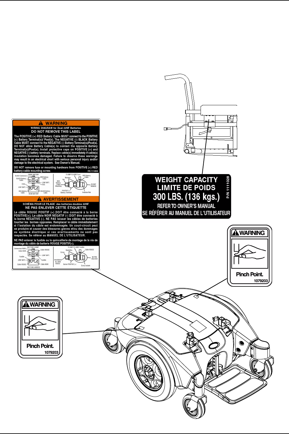
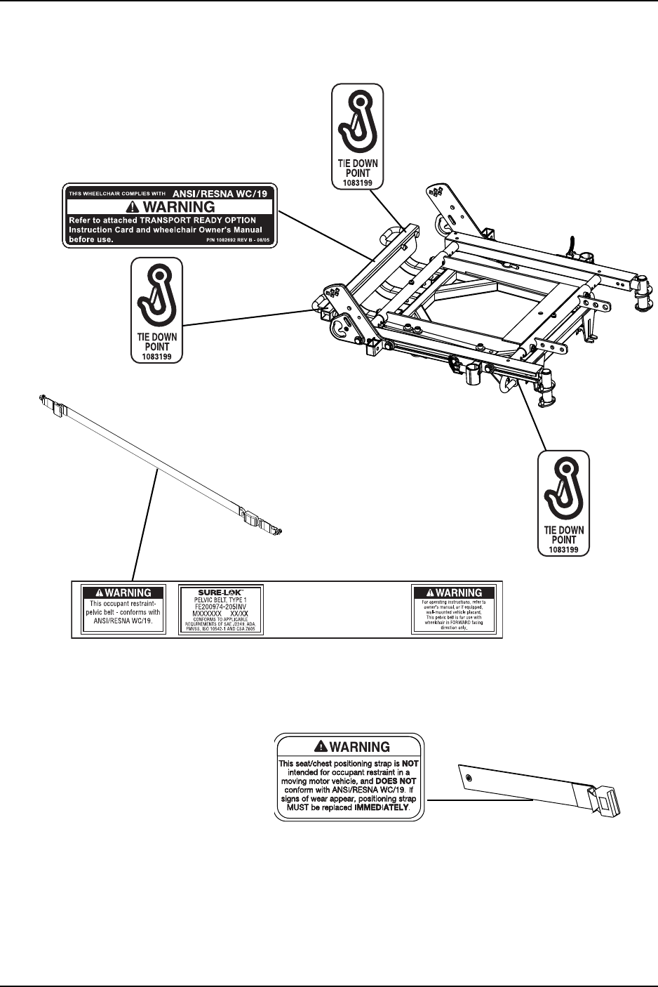
Wheelchairs With TRRO
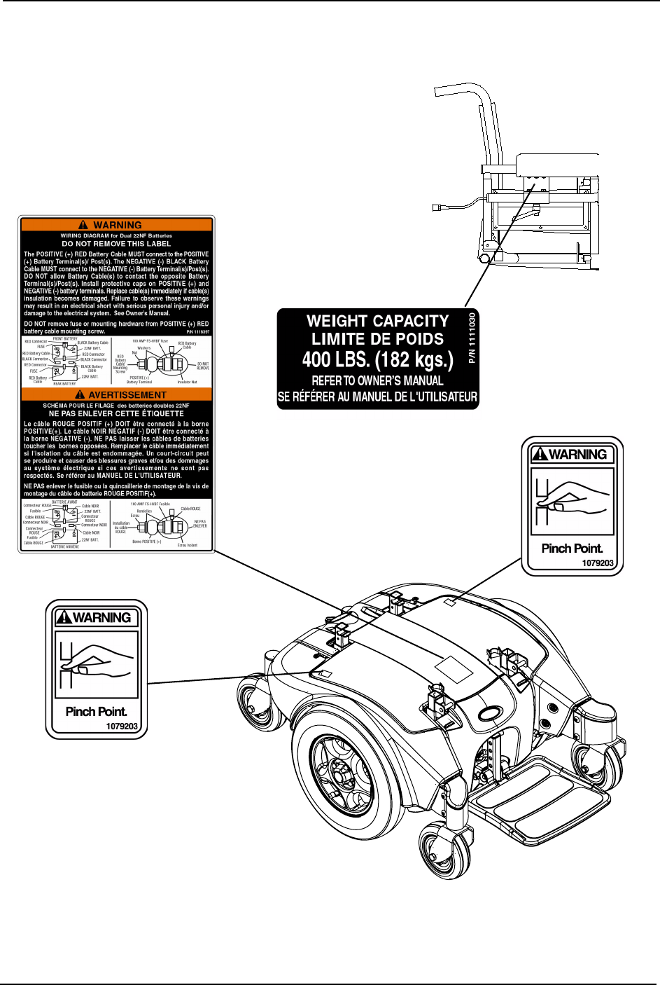
Wheelchairs Without TRRO
NOTE:Also
onopposite
side.
NOTE:Also
onopposite
side.
NOTE:Also
onopposite
side.
NOTE:Autostyleseatpositioning
strapshown.Thislabelisalsoonthe
airlinestyleseatpositioningstrap.

TYPICAL PRODUCT PARAMETERS
Pronto® M91™Base with SureStep® 12 Part No 1143153
TYPICAL PRODUCT PARAMETERS
Pronto M91
NOTE:Basedon18‐inchdeepVanseat.
*NOTE:Valuesforrangearecalculatedformaximumchairweightratingusinglargestbatteries
applicable(22NF),pertestproceduresdescribedinANSI/RESNAWC/VOL2‐1998Section4and
meetfederalreimbursementrequirementsforthisproduct.Whileconsideredtypical,theyare
derivedbasedoncertainidealconditions.Variancesinbatterycondition,userweight,usage
patternoroverallterrainconditionswillresultinactualvaluesforrangethatdifferfromthese
statedvalues.Usersshouldbecomeaccustomedtohowtheiruniqueconditionsimpacttheir
individualresults.Usersshouldbecomefamiliarwiththebatterydischargeindicatoronthe
joysticktodeterminetherangeoftheirwheelchair.RefertoBatteryChargerOperationonpage 64
formoreinformationaboutthebatterydischargeindicator.
**NOTE:RefertoStabilityandBalanceonpage 20.
18-INCH
VAN SEAT
20-INCH
VAN SEAT
22-INCH
VAN SEAT
ADJUSTABLE
ASBA SEAT
SEAT-TO-FLOOR: 22½ to 23½ inches
(Cushion Not Compressed)
20-22 inches
(To Seat Pan)
OVERALL WIDTH (NO JOYSTICK):
25-7/8 inches
OVERALL HEIGHT: 36-49¼ inches (Semi Recline Back)
OVERALL LENGTH: 39 inches (With Footboard Folded)
DRIVE WHEELS/TIRES: 14 x 3-inch
CASTERS: 6 x 2-inch Front/Rear with Precision Sealed Bearings
WEIGHT W/SEATING SYSTEM
AND ACCESSORIES
W/O BATTERIES:
W/BATTERIES:
199 lbs
273 lbs
SHIPPING: 260 lbs (w/o Batteries), 310 lbs (w/Batteries)
BATTERIES: 22NF - Quantity 2
INCLINE CAPABILITY: 9°
PERFORMANCE
SPEED
Standard:
Heavy Duty:
TURNING RADIUS:
*RANGE (VARIABLE)
Standard:
Heavy Duty:
**WEIGHT LIMITATION
Standard:
Heavy Duty:
0 to 6.4 mph
0 to 4.25 mph
19½ inches (Front with Footboard); 21½ inches (Rear)
22 miles
12-16 miles
300 lbs
400 lbs

SECTION 1—GENERAL GUIDELINES
Part No 1143153 13 Pronto® M91™Base with SureStep®
SECTION 1—GENERAL GUIDELINES
WARNING
SECTION 1 - GENERAL GUIDELINES contains important information for the safe
operation and use of this product.
Controller Settings/Repair or Service
Set‐upoftheElectronicControlUnitistobeperformedONLYbyaqualifiedtechnician.
Thefinaladjustmentsofthecontrollermayaffectotheractivitiesofthewheelchair.
Damagetotheequipmentcouldoccurifimproperlyset‐uporadjusted.
DONOTserviceoradjustyourwheelchairwhileoccupied,unlessotherwisenoted.
Wheelchairsshouldbeexaminedduringmaintenanceforsignsofcorrosion(water
exposure,incontinence,etc.).Electricalcomponentsdamagedbycorrosionshouldbe
replacedIMMEDIATELY.
Wheelchairsthatareusedbyincontinentusersand/orarefrequentlyexposedtowater
mayrequirereplacementofelectricalcomponentsmorefrequently.
TRANSPORTREADYPACKAGESARENOTRETROFITTABLETOEXISTING
MODELSANDARENOTFIELDSERVICEABLE.
Accessories Information
EXTREMEcareshouldbeexercisedwhenusingoxygenincloseproximitytoelectric
circuitsandothercombustiblematerials.Contactyouroxygensupplierforinstructionin
theuseofoxygen.
Operation Information
Performanceadjustmentsshouldonlybemadebyprofessionalsofthehealthcarefieldor
personsfullyconversantwiththisprocessandthedriverʹscapabilities.Incorrectsettings
couldcauseinjurytothedriver,bystanders,damagetothewheelchairandto
surroundingproperty.
Afterthewheelchairhasbeenset‐up,checktomakesurethatthewheelchairperformsto
thespecificationsenteredduringtheset‐upprocedure.IfthewheelchairdoesNOT
performtospecifications,turnthewheelchairOffIMMEDIATELYandreenterset‐up
specifications.Repeatthisprocedureuntilthewheelchairperformstospecifications.
ALWAYSshiftyourweightinthedirectionyouareturning.DONOTshiftyourweightin
theoppositedirectionoftheturn.Shiftingyourweightintheoppositedirectionofthe
turnmaycausetheinsidedrivewheeltolosetractionandthewheelchairtotipover.
DONOTshiftyourweightorsittingpositiontowardthedirectionyouarereachingasthe
wheelchairmaytipover.

SECTION 1—GENERAL GUIDELINES
Pronto® M91™Base with SureStep® 14 Part No 1143153
DONOTmakesharpturnsintheforwardorreversedirectionatexcessivespeed.Failure
toobservethiswarningcancausethewheelchairtotipoverandmayresultininjuryto
users,bystandersand/ordamagetoproduct.
DOdetermineandestablishyourparticularsafetylimitsbypracticingbending,reaching
andtransferringactivitiesinthepresenceofaqualifiedhealthcareprofessionalbefore
attemptingactiveuseofthewheelchair.
DONOTattempttoreachobjectsifyouhavetomoveforwardintheseat.
DONOTattempttoreachobjectsifyouhavetopickthemupfromthefloorbyreaching
downbetweenyourknees.
DONOTleanoverthetopofthebackupholsterytoreachobjectsbehindyou,asthismay
causethewheelchairtotipover.
ALWAYSkeephandsandfingersclearofmovingpartstoavoidinjury.
DONOTstoreitemsunderseat‐interferencewithseatlatchmayresult.
DONOTuseanescalatortomoveawheelchairbetweenfloors.Seriousbodilyinjurymay
occur.
DONOTengageordisengagethemotorreleaseleversuntilthepowerisintheOff
position.
DONOTattempttostopamovingwheelchairwithwheellocks.Wheellocksarenot
brakes.
DONOToperateonroads,streetsorhighways.
DONOTclimb,goupordownrampsortraverseslopesgreaterthan9°.
NEVERleaveanunoccupiedwheelchaironanincline.
Invacarestronglyrecommendsproceedingdownrampsorslopesathalfspeedorslower
andtoavoidhardbrakingorsuddenstops.
DONOTleaveelevatinglegrestsinthefullyextendedpositionwhenproceedingdown
rampsorslopes.
DONOTattempttomoveupordownaninclinewithawater,iceoroilfilm.
DONOTattempttodriveovercurbsorobstacles.Doingsomaycauseyourwheelchair
toturnoverandcausebodilyharmordamagetothewheelchair.
DONOTleavethepowerbuttonintheOnpositionwhenenteringorexitingyour
wheelchair.
DONOTattempttoliftthewheelchairbyanyremovable(detachable)parts.Liftingby
meansofanyremovable(detachable)partsofthewheelchairmayresultininjurytothe
userordamagetothewheelchair.
DONOTstandontheframeofthewheelchair.
DONOTstandonthefootplates/footboard.Whengettinginoroutofthewheelchair,
makesurethatthefootboardorfootplatesareintheupwardpositionorswingthe
footreststowardstheoutsideofthewheelchair.

SECTION 1—GENERAL GUIDELINES
Part No 1143153 15 Pronto® M91™Base with SureStep®
Makesuredetentballsofthequick‐releasepinarefullyreleasedbeforeoperatingthe
wheelchair.
Keepdetentballsclean.
Whendeterminingthedepthofthetelescopingfrontframetubes,makesuretherearof
thefootrestsdonotinterferewiththemovementofthefrontcasters.Otherwisedamage
tothewheelchairmayresultormayimpedeproperoperation.
Beforeattemptingtotransferinoroutofthewheelchair,everyprecautionshouldbe
takentoreducethegapdistance.Turnbothcastersparalleltotheobjectyouare
transferringonto.AlsobecertainthepowerisOffandwheellocksareengagedtoprevent
thewheelsfrommoving.
DONOTadjusttherearseatpostshigherthanthefrontseatposts.
Beforeperforminganymaintenance,adjustmentorserviceverifythatOn/Offswitchon
thejoystickisintheOffposition.
ALWAYSwearyourseatpositioningstrap.Theseatpositioningstrapisapositioningbelt
only.Itisnotdesignedforuseasasafetydevicewithstandinghighstressloadssuchas
autooraircraftsafetybelts.Ifsignsofwearappear,beltmustbereplacedIMMEDIATELY.
Withregardstoseat/chestpositioningstraps‐itistheobligationoftheDMEdealer,
therapistsandotherhealthcareprofessionalstodetermineifaseat/chestpositioningstrap
isrequiredtoensurethesafeoperationofthisequipmentbytheuser.Seriousinjurycan
occurintheeventofafallfromawheelchair.
Avoidstoringorusingthewheelchairnearopenflameorcombustibleproducts.Serious
injuryordamagetopropertymayresult.
Batteries
Thewarrantyandperformancespecificationscontainedinthismanualarebasedonthe
useofdeepcyclegelcellbatteries.Invacarestronglyrecommendstheiruseasthepower
sourceforthisunit.
Carefullyreadbattery/batterychargerinformationpriortoinstalling,servicingor
operatingyourwheelchair.
DONOTremovefuseormountinghardwarefromPOSITIVE(+)REDbatterycable/
mountingscrew.
Allbatteryterminalcovers(twoonthefrontbatteryandtwoontherearbattery)MUST
beinstalledpriortouse.
Theuseofrubberglovesisrecommendedwhenworkingwithbatteries.
Somebatterymanufacturersmoldacarryingstrapand/orholddownflangesdirectlyinto
thebatterycase.Batteriesthatinterferewiththebatteryboxcannotbeusedforthese
applications.Attemptingto“wedge”abatteryintoabatteryboxmaydamagethebox,
thebatteryand/orbeafirehazard,resultinginseriousinjuryorfurtherdamageto
property.

SECTION 1—GENERAL GUIDELINES
Pronto® M91™Base with SureStep® 16 Part No 1143153
Charging Batteries
DANGER
When using an extension cord, use only a three wire extension cord having at least
16 AWG (American Wire Gauge) wire and the same or higher electrical rating as
the devise being connected. Use of improper extension cord could result in a risk of
fire and electric shock. Three prong to two prong adapters should not be used. Use
of three prong adapters can result in improper grounding and present a shock
hazard to the user.
NEVERattempttorechargethebatteriesbyattachingcablesdirectlytothebatteryterminals.
DONOTattempttorechargethebatteriesandoperatethewheelchairatthesametime.
DONOToperatewheelchairwithextensioncordattachedtotheACcable.
DONOTattempttorechargethebatterieswhenthewheelchairhasbeenexposedtoANY
typeofmoisture.
DONOTattempttorechargethebatterieswhenthewheelchairisoutside.
DONOTsitinthewheelchairwhilechargingthebatteries.
DONOTattempttorechargebatteriesusingBOTHtheon‐boardbatterychargerandan
independentbatterycharger(pluggedintothejoystickchargerport)attheSAMEtime.
Doingsowillreducethelifeofthebatteries.
READandCAREFULLYfollowthemanufacturer’sinstructionsforeachcharger
(suppliedorpurchased).Ifcharginginstructionsarenotsupplied,consultaqualified
technicianforproperprocedures.
AFTERchargingbatteries,ALWAYSmakesurethatthebatterychargercordissecurely
wrappedandstoredwithinthehookandloopstrapassemblyontherearofthebattery
tray.Failuretodosomayresultindamagetothecordorpersonalinjurytotheuseror
bystanders.
Ensurethepinsoftheextensioncordplugarethesamenumber,size,andshapeasthose
onthecharger.
DONOTunderanycircumstancescutorremovetheroundgroundingplugfromthe
chargerACcableplugortheextensioncordplug.
Grounding Instructions
DONOT,underanycircumstances,cutorremovetheroundgroundingprongfromany
plugusedwithorforInvacareproducts.Somedevicesareequippedwiththree‐prong
(grounding)plugsforprotectionagainstpossibleshockhazardsandfire.Whereatwo‐
prongwallreceptacleisencountered,itisthepersonalresponsibilityandobligationofthe
customertocontactaqualifiedelectricianandhavethetwo‐prongreceptaclereplacedwith
aproperlygroundedthree‐prongwallreceptacleinaccordancewiththeNationalElectrical
Code.Ifyoumustuseanextensioncord,useONLYathree‐wireextensioncordhavingthe
sameorhigherelectricalratingasthedevicebeingconnected.Inaddition,Invacarehas
placedRED/ORANGEwarningtagsonsomeequipment.DONOTremovethesetags.

SECTION 1—GENERAL GUIDELINES
Part No 1143153 17 Pronto® M91™Base with SureStep®
Rain Test
InvacarehastesteditspowerwheelchairsinaccordancewithISO7176“RainTest.”This
providestheenduserorhis/herassistantsufficienttimetoremovehis/herpower
wheelchairfromarainstormandretainwheelchairoperation.
DONOTleavepowerwheelchairinarainstormofanykind.
DONOTusepowerwheelchairinashower.
DONOTstorepowerwheelchairinadampareaforanextendedperiodoftime.
Directexposuretoexcessiverainordampnessmaycausethewheelchairtomalfunction
electricallyandmechanically,maycausethewheelchairtoprematurelyrustormay
damagetheupholstery.
ChecktoensurethattheREDandBLACKbatteryterminalcapsaresecuredinplace,
joystickbootisNOTtornorcrackedwherewatercanenterandthatallelectrical
connectionsaresecureatalltimes.
DONOTusethewheelchairifthejoystickbootistornorcracked.Ifthejoystickboot
becomestornorcracked,replaceIMMEDIATELY.
Weight Training
InvacareDOESNOTrecommendtheuseofitswheelchairsasaweighttraining
apparatus.InvacarewheelchairshaveNOTbeendesignedortestedasaseatforanykind
ofweighttraining.Ifoccupantusessaidwheelchairasaweighttrainingapparatus,
InvacareshallNOTbeliableforbodilyinjuryandthewarrantyisvoid.
Weight Limitation
TheProntoM91wheelchairshavethefollowingweightlimitations:
MODEL WEIGHT LIMITATION
STANDARD 300 lb
HEAVY DUTY 400 lb

SECTION 2—EMI INFORMATION
Pronto® M91™Base with SureStep® 18 Part No 1143153
SECTION 2—EMI INFORMATION
WARNING
CAUTION: IT IS VERY IMPORTANT THAT YOU READ THIS INFORMATION
REGARDING THE POSSIBLE EFFECTS OF ELECTROMAGNETIC
INTERFERENCE ON YOUR POWERED WHEELCHAIR.
Electromagnetic Interference (EMI) From Radio Wave Sources
Powered wheelchairs and motorized scooters (in this text, both will be referred to
as powered wheelchairs) may be susceptible to electromagnetic interference (EMI),
which is interfering electromagnetic energy (EM) emitted from sources such as
radio stations, TV stations, amateur radio (HAM) transmitters, two way radios, and
cellular phones. The interference (from radio wave sources) can cause the powered
wheelchair to release its brakes, move by itself, or move in unintended directions. It
can also permanently damage the powered wheelchair's control system. The
intensity of the interfering EM energy can be measured in volts per meter (V/m).
Each powered wheelchair can resist EMI up to a certain intensity. This is called its
"immunity level." The higher the immunity level, the greater the protection. At this
time, current technology is capable of achieving at least a 20 V/m immunity level,
which would provide useful protection from the more common sources of radiated
EMI.
There are a number of sources of relatively intense electromagnetic fields in the
everyday environment. Some of these sources are obvious and easy to avoid.
Others are not apparent and exposure is unavoidable. However, we believe that by
following the warnings listed below, your risk to EMI will be minimized.
The sources of radiated EMI can be broadly classified into three types:
1) Hand-held Portable transceivers (transmitters-receivers with the antenna
mounted directly on the transmitting unit. Examples include: citizens band (CB)
radios, "walkie talkie", security, fire and police transceivers, cellular telephones,
and other personal communication devices).
NOTE: Some cellular telephones and similar devices transmit signals while they are ON,
even when not being used.
2) Medium-range mobile transceivers, such as those used in police cars, fire trucks,
ambulances and taxis. These usually have the antenna mounted on the outside of
the vehicle; and
3) Long-range transmitters and transceivers, such as commercial broadcast
transmitters (radio and TV broadcast antenna towers) and amateur (HAM)
radios.
NOTE: Other types of hand-held devices, such as cordless phones, laptop computers,
AM/FM radios, TV sets, CD players, cassette players, and small appliances, such as elec-
tric shavers and hair dryers, so far as we know, are not likely to cause EMI problems to
your powered wheelchair.

SECTION 2—EMI INFORMATION
Part No 1143153 19 Pronto® M91™Base with SureStep®
WARNING
Powered Wheelchair Electromagnetic Interference (EMI)
Because EM energy rapidly becomes more intense as one moves closer to the
transmitting antenna (source), the EM fields from hand-held radio wave sources
(transceivers) are of special concern. It is possible to unintentionally bring high
levels of EM energy very close to the powered wheelchair's control system while
using these devices. This can affect powered wheelchair movement and braking.
Therefore, the warnings listed below are recommended to prevent possible
interference with the control system of the powered wheelchair.
Electromagnetic interference (EMI) from sources such as radio and TV stations,
amateur radio (HAM) transmitters, two-way radios, and cellular phones can affect
powered wheelchairs and motorized scooters.
FOLLOWING THE WARNINGS LISTED BELOW SHOULD REDUCE THE
CHANCE OF UNINTENDED BRAKE RELEASE OR POWERED WHEELCHAIR
MOVEMENT WHICH COULD RESULT IN SERIOUS INJURY.
1) Do not operate hand-held transceivers (transmitters receivers), such as citizens
band (CB) radios, or turn ON personal communication devices, such as cellular
phones, while the powered wheelchair is turned ON;
2) Be aware of nearby transmitters, such as radio or TV stations, and try to avoid
coming close to them;
3) If unintended movement or brake release occurs, turn the powered wheelchair
OFF as soon as it is safe;
4) Be aware that adding accessories or components, or modifying the powered
wheelchair, may make it more susceptible to EMI (NOTE: There is no easy way
to evaluate their effect on the overall immunity of the powered wheelchair); and
5) Report all incidents of unintended movement or brake release to the powered
wheelchair manufacturer, and note whether there is a source of EMI nearby.
Important Information
1) 20 volts per meter (V/m) is a generally achievable and useful immunity level
against EMI (as of May 1994) (the higher the level, the greater the protection);
2) This device has been tested to a radiated immunity level of 20 volts per meter;
3) The immunity level of the product is unknown.
Modification of any kind to the electronics of this wheelchair as manufactured by
Invacare may adversely affect the EMI immunity levels.

SECTION 3—SAFETY/HANDLING OF WHEELCHAIRS
Pronto® M91™Base with SureStep® 20 Part No 1143153
SECTION 3—SAFETY/HANDLING OF
WHEELCHAIRS
“SafetyandHandling”ofthewheelchairrequiresthecloseattentionofthewheelchair
useraswellastheassistant.Thismanualpointsoutthemostcommonproceduresand
techniquesinvolvedinthesafeoperationandmaintenanceofthewheelchair.Itis
importanttopracticeandmasterthesesafetechniquesuntilyouarecomfortablein
maneuveringaroundthefrequentlyencounteredarchitecturalbarriers.
Usethisinformationonlyasa“basic”guide.Thetechniquesthatarediscussedonthe
followingpageshavebeenusedsuccessfullybymany.
Individualwheelchairusersoftendevelopskillstodealwithdailylivingactivitiesthat
maydifferfromthosedescribedinthismanual.Invacarerecognizesandencourageseach
individualtotrywhatworksbestforhim/herinovercomingarchitecturalobstaclesthat
theymayencounter,howeverALLWARNINGSandCAUTIONSgiveninthismanual
MUSTbefollowed.Techniquesinthismanualareastartingpointforthenewwheelchair
userandassistantwith“safety”asthemostimportantconsiderationforall.
Stability and Balance
WARNING
ALWAYS wear your seat positioning strap. The seat positioning strap is a
positioning belt ONLY. It is not designed for use as a safety device withstanding high
stress loads such as auto or aircraft safety belts. If signs of wear appear, belt must be
replaced IMMEDIATELY.
DO NOT climb, go up or down ramps or traverse slopes greater than 9°.
Invacare strongly recommends proceeding down ramps or slopes at half speed or
slower and to avoid hard braking or sudden stops.
DO NOT leave elevating legrests in the fully extended position when proceeding
down ramps or slopes.
Be aware that carrying heavy objects on your lap while occupying the wheelchair
may adversely affect the stability of the wheelchair, resulting in serious bodily injury
to the user, damage to the wheelchair and surrounding property.
This wheelchair has been designed to accommodate one individual. If more than
one individual occupies the wheelchair this may adversely affect the stability of the
wheelchair, resulting in serious bodily injury to the user and passenger and damage
to the wheelchair and surrounding property.
Proper positioning is essential for your safety. When reaching, leaning, bending or
bending forward, it is important to use the casters as a tool to maintain stability and
balance.
DO NOT attempt to reach objects if you have to move forward in the seat or pick
them up from the floor by reaching down between your knees.

SECTION 3—SAFETY/HANDLING OF WHEELCHAIRS
Part No 1143153 21 Pronto® M91™Base with SureStep®
WARNING
Many activities require the wheelchair user to reach, bend and transfer in and out of
the wheelchair. These movements will cause a change to the normal balance,
center of gravity, and weight distribution of the wheelchair. To determine and
establish your particular safety limits, practice bending, reaching and transferring
activities in several combinations in the presence of a qualified healthcare
professional BEFORE attempting active use of the wheelchair.
The Pronto M91 wheelchairs have the following weight limitations:
Toassurestabilityandproperoperationofyourwheelchair,youmustatalltimes
maintainproperbalance.Yourwheelchairhasbeendesignedtoremainuprightand
stableduringnormaldailyactivitiesaslongasyoudonotmovebeyondthecenterof
gravity.DONOTleanforwardoutofthewheelchairanyfurtherthanthelengthofthe
armrests.
Coping With Everyday Obstacles
NOTE:Forthisprocedure,referto
FIGURE 3.1.
Copingwiththeirritationofeveryday
obstaclescanbealleviatedsomewhatby
learninghowtomanageyourwheelchair.
Keepinmindyourcenterofgravityto
maintainstabilityandbalance.
FIGURE 3.1 Coping With Everyday
Obstacles
Whilethewalkingbeamallowstotraverseuptoa3‐inchbumporthreshold,stopping
afterthewheelscrossthebumpposesaproblem.Thewheelchaircannotreverseoverthe
bumpatthispoint.Continueforwardandthenturnaround.
WhiletheM91isdesignedforuseprimarilyinandaroundthehome,theprovidershould
determinewhetherthiswheelchairissuitablefortheactualenvironmentthewheelchair
willbeusedin.
DONOTgodownrampatfullspeed.Someseat/backpositionswillcausewheelchairto
feelunstable.
CAUTION
Be aware of condition of ramp. Traction will be diminished/nonexistent on a slip-
pery surface. Proceed with caution.
MODEL WEIGHT LIMITATION
STANDARD 300 lb
HEAVY DUTY 400 lb
3-inch Bump
or Threshold
SECTION 3—SAFETY/HANDLING OF WHEELCHAIRS
Pronto® M91™Base with SureStep® 22 Part No 1143153
Pinch Points
WARNING
Pinch point may occur when returning
the tilted seat to the full upright
position. Make sure the hands and body
of the occupant, attendants and
bystanders are clear of all pinch points
before lowering seat (FIGURE 3.2).
DO NOT store or place items under the
seat.
NOTE:Forthisprocedure,referto
FIGURE 3.2andFIGURE 3.3.
FIGURE 3.2 Pinch Points
WARNING
Pinch point may occur when adjusting the arm angle position (Detail “A”).
Pinch point may occur when rotating the footboard assembly (Detail “B”).
FIGURE 3.3 Pinch Points
A Note to Wheelchair Assistants
Whenassistancetothewheelchairuserisrequired,remembertousegoodbody
mechanics.Keepyourbackstraightandbendyourkneeswhenevertiltingwheelchairor
traversingcurbsorotherimpediments.
Also,beawareofdetachablepartssuchasarmsorlegrests.ThesemustNEVERbeused
tomovethewheelchairorasliftingsupports,astheymaybeinadvertentlyreleased,
resultinginpossibleinjurytotheuserand/orassistant(s).
Whenlearninganewassistancetechnique,haveanexperiencedassistanthelpyoubefore
attemptingitalone.
Pinch
Point
Pinch
Point
Pinch Point
DETAIL “A” DETAIL “B”

SECTION 3—SAFETY/HANDLING OF WHEELCHAIRS
Part No 1143153 23 Pronto® M91™Base with SureStep®
Lifting/Stairways
WARNING
DO NOT attempt to move an occupied power wheelchair between floors using a
stairway. Use an elevator to move an occupied power wheelchair between floors. If
moving a power wheelchair between floors by means of a stairway, the occupant
MUST be removed and transported independently of the power wheelchair.
Extreme caution is advised when it is necessary to move an unoccupied power
wheelchair up or down the stairs. Invacare recommends using two assistants and
making thorough preparations.
Use ONLY secure, nondetachable parts for hand-hold supports.
It is strongly recommended to lift the wheelchair only by the rear frame and the
front forks - otherwise injury or damage may occur.
DO NOT attempt to lift the wheelchair by any removable (detachable) parts.
Lifting by means of any removable (detachable) parts of a wheelchair may result in
injury to the user or damage to the wheelchair.
The weight of the wheelchair with batteries and without the user is between 203
and 318 lbs. Use proper lifting techniques (lift with your legs) to avoid injury.
NOTE:Forthisprocedure,refertoFIGURE 3.4.
FollowthisprocedureformovingthewheelchairbetweenfloorswhenanelevatorisNOT
availableorliftingthewheelchairisnecessary:
1. Removetheoccupantfromthe
wheelchair.
2. Bendyourkneesandkeepyourback
straight.
3. Usingtherearframeandthefrontedge
ofthefrontforksashandhold
supports,transferthewheelchairbase
tothedesiredlocation. FIGURE 3.4 Lifting/Stairways - Hand Hold
Supports
WARNING: ESCALATORS
DO NOT use an escalator to move a wheelchair between floors. Serious bodily
injury may occur.
Rear Frame Front Forks
(Front Edge)
SECTION 3—SAFETY/HANDLING OF WHEELCHAIRS
Pronto® M91™Base with SureStep® 24 Part No 1143153
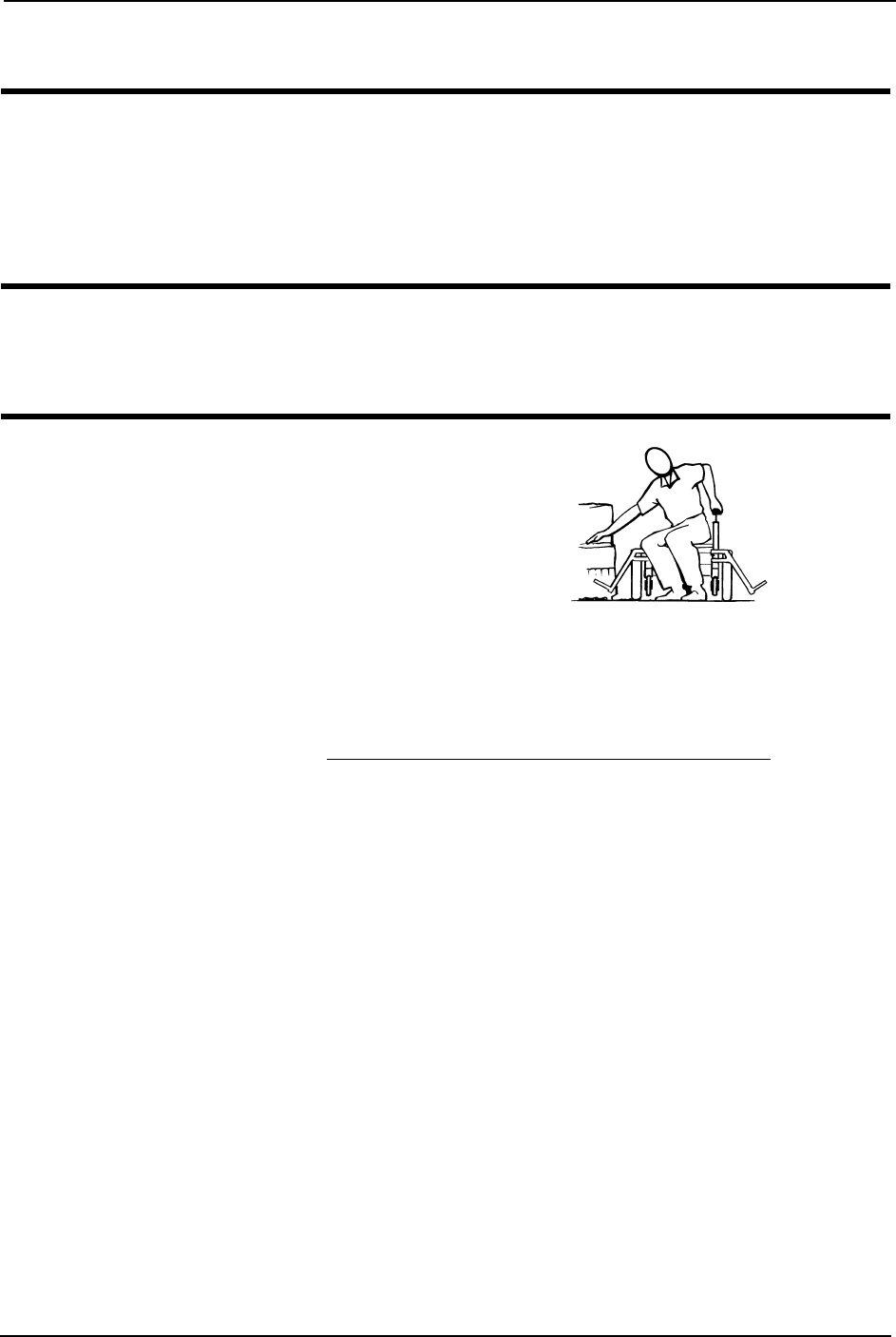
Transferring To and From Other Seats
WARNING
ALWAYS turn the wheelchair power Off and engage the motor release levers to
prevent the wheels from moving before attempting to transfer in or out of the
wheelchair. Also, make sure every precaution is taken to reduce the gap distance by
aligning both the front AND rear casters parallel with the object you are
transferring onto.
CAUTION
When transferring, position yourself as far back as possible in the seat. This will
prevent broken screws, damaged upholstery and the possibility of the wheelchair
tipping forward.
NOTE:Forthisprocedure,referto
FIGURE 3.5.
NOTE:Thisactivitymaybeperformed
independentlyprovidedyouhaveadequate
mobilityandupperbodystrength.
1. Positionthewheelchairascloseas
possiblealongsidetheseattowhich
youaretransferring,withtherear
casterspointingawayfromit.
FIGURE 3.5 Transferring To and From
Other Seats
2. Afterthewheelchairispositionedproperlyfortransfer,verifythattheMotorRelease
Leversareengaged.RefertoEngaging/DisengagingMotorReleaseLeveronpage 54.
3. Flipbackorremovearmonsideofwheelchairyouaretransferringfrom.
4. Shiftbodyweightintoseatwithtransfer.
Duringindependenttransfer,littleornoseatplatformwillbebeneathyou.Useatransfer
boardifatallpossible.

SECTION 3—SAFETY/HANDLING OF WHEELCHAIRS
Part No 1143153 25 Pronto® M91™Base with SureStep®
Reaching, Leaning andBending - Forward
WARNING
DO NOT attempt to reach objects if you have to move forward in the seat or pick
them up from the floor by reaching down between your knees.
NOTE:Forthisprocedure,refertoFIGURE 3.6.
Positionthefrontandrearcasterssothattheyareextendedasfarforwardaspossibleand
engageMotorReleaseLevers.
FIGURE 3.6 Reaching, Leaning and Bending - Forward
Reaching and Bending - Backward
WARNING
DO NOT lean over the top of the back upholstery. This will change your center of
gravity and may cause you to tip over.
NOTE:Forthisprocedure,refertoFIGURE 3.7.
Positionwheelchairascloseaspossibletothedesiredobject.Pointthefrontandrear
castersrearwardtocreatethelongestpossiblewheelbase.Reachbackonlyasfarasyour
armwillextendwithoutchangingyoursittingposition.
FIGURE 3.7 Reaching and Bending - Backward

SECTION 4—SAFETY INSPECTION/TROUBLESHOOTING
Pronto® M91™Base with SureStep® 26 Part No 1143153
SECTION 4—SAFETY INSPECTION/
TROUBLESHOOTING
NOTE:Everysixmonthsorasnecessarytakeyourwheelchairtoaqualifieddealerforathorough
inspectionandservicing.Regularcleaningwillreveallooseorwornpartsandenhancethesmooth
operationofyourwheelchair.Tooperateproperlyandsafely,yourwheelchairmustbecaredforjust
likeanyothervehicle.Routinemaintenancewillextendthelifeandefficiencyofyourwheelchair.
Safety Inspection Checklists
CAUTION
As with any vehicle, wheels and tires should be checked periodically for cracks and
wear and should be replaced as necessary.
Initialadjustmentsshouldbemadetosuityourpersonalbodystructureneedsand
preference.Thereafterfollowthesemaintenanceprocedures:
Inspect/Adjust Initially
❑Ensurewheelchairrollsstraight(noexcessivedragorpulltooneside).
❑Ensurearmsaresecurebuteasytoreleaseandadjustmentleversengageproperly(on
ASBAonly).
❑Ensureadjustableheightarmsoperateandlocksecurely.
❑Ensurearmrestpadssitflushagainstarmtubes.
❑Ensureseatissecuredtowheelchairframe.
❑Ensureseatreleaselatchisfunctional.Replaceifnecessary.
❑Ensurewheelmountingnutsaresecureondrivewheels.
❑Ensurethereisnoexcessivesidemovementorbindingwhendrivewheelsarelifted
andspunwhendisengaged(freewheeling).
❑Ensurewheel/forkassemblyhaspropertensionwhencasterisspun.Castershould
cometoagradualstop.
❑Loosen/tightencasterlocknutifwheelwobblesnoticeablyorbindstoastop.
❑Ensureallcaster/wheel/fork/headtubefastenersaresecure.
❑Inspecttiresforflatspotsandwear.
❑Inspectandcleanthestabilitylockgears.
❑Cleanupholsteryandarmrests.
❑Checkthatalllabelsarepresentandlegible.Replaceifnecessary.
❑Ensurecastersarefreeofdebris.

SECTION 4—SAFETY INSPECTION/TROUBLESHOOTING
Part No 1143153 27 Pronto® M91™Base with SureStep®
Inspect/Adjust Weekly
❑Ensureseatissecuredtowheelchairframe.
❑Ensureseatand/orbackupholsteryhavenoripsanddonotsag.Replaceifnecessary.
❑Ensureseatreleaselatchisnotwornandisfunctional.Replaceifnecessary.
❑Inspecttiresforflatspotsandwear.
❑Ensurearmpivotpointsarenotwornand/orloose.Replaceifnecessary.
❑Inspectandcleanthestabilitylockgears.Replaceifworn.
❑Ensurecastersarefreeofdebris.
Inspect/Adjust Monthly
❑Ensurewheelmountingnutsaresecureondrivewheels.
❑Ensurethereisnoexcessivesidemovementorbindingwhendrivewheelsarelifted
andspunwhendisengaged(free‐wheeling).
❑Ensurewheel/forkassemblyhaspropertensionwhencasterisspun.Castershould
cometoagradualstop.
❑Loosen/tightencasterlocknutifwheelwobblesnoticeablyorbindstoastop.
❑Ensureallcaster/wheel/fork/headtubefastenersaresecure.
❑Inspectforanyloosehardwareonthewheelchair.
❑Inspecttheseatpositioningstrapforsignsofwear.Replaceifwornordamaged.
❑Ensurethatthebuckleontheseatpositioningstraplatches.Replaceifnecessary.
❑Verifythatthehardwarethatattachestheseatpositioningstraptotheseatframeis
secureandundamaged.Replaceifnecessary.
❑Ensurecastersarefreeofdebris.
Inspect/Adjust Periodically
❑Ensurewheelchairrollsstraight(noexcessivedragorpulltooneside).
❑Ensurethatcastersarefreeofdebris.
❑Ensurearmsaresecurebuteasytoreleaseandadjustmentleversengageproperly(on
ASBAonly).
❑Ensureadjustableheightarmsoperateandlocksecurely.
❑Ensurearmpivotpointsarenotwornand/orloose.Replaceifnecessary.
❑Ensurearmrestpadssitflushagainstarmtubes.
❑Ensureseatand/orbackupholsteryhavenoripsanddonotsag.Replaceifnecessary.
❑Inspectelectricalcomponentsforsignsofcorrosion.Replaceifcorrodedordamaged.
❑Ensureseatreleaselatchisnotworn.Replaceifnecessary.

SECTION 4—SAFETY INSPECTION/TROUBLESHOOTING
Pronto® M91™Base with SureStep® 28 Part No 1143153
❑Inspectandcleanthestabilitylockgears.Replaceifworn.
❑Cleanupholsteryandarmrests.
❑InspectchargerACpowercordfordamage.Replaceifnecessary.
❑CheckthatwiringisroutedandsecuredproperlytoensurethatwiringdoesNOT
becomeentangledanddamaged.
❑Inspectelectricalcomponentsforsignsofcorrosion.Replaceifcorrodedordamaged.
❑Checkthatalllabelsarepresentandlegible.Replaceifnecessary.
❑Ensurecastersarefreeofdebris.
Troubleshooting - Mechanical
Troubleshooting - Electrical
NOTE:Foradditionaltroubleshootinginformationandexplanationoferrorcodes,refertothe
individualElectronicsManualsuppliedwitheachwheelchair
SPJ+, SPJ+ w/PSS or SPJ+ w/ACC Joysticks
Thejoystickinformationgaugeandtheserviceindicatorgiveindicationsofthetypeof
faultorerrordetectedbythecontrolmodule.Whenafaultisdetected,thewheelchair
maystopandnotdrive.TheLEDsontheinformationgaugemayflashinaparticular
patternortheserviceindicatorlightwillflash.Thenumberortypeofflashesindicatesthe
natureoftheerror.Ifmultipleerrorsarefound,onlythefirsterrorencounteredbythe
controlmodulewillbedisplayed.
WHEELCHAIR VEERS
LEFT/RIGHT
SLUGGISH
TURN/
PERFORMANCE
CASTERS
FLUTTER
SQUEAKS AND
RATTLES
LOOSENESS
IN WHEELCHAIR
WHEELCHAIR 3
WHEELS
SOLUTIONS
X X X If pneumatic, check tires for correct and equal pressure.
X X X X Check for loose stem nuts/bolts.
X X Check that casters contact ground at the same time.

SECTION 4—SAFETY INSPECTION/TROUBLESHOOTING
Part No 1143153 29 Pronto® M91™Base with SureStep®
Information Gauge Display Diagnostics
Service Indicator Light Diagnostics
DISPLAY DESCRIPTION DEFINITION COMMENTS
All LEDs are off. Power is off.
All LEDs are on. Power is on. Fewer than three LEDs on
implies reduced battery
charge.
Left RED LED is flashing. Battery charge is low. The batteries should be
charged as soon as
possible.
Left to Right “chase”
alternating with steady
display.
Joystick is in
programming, inhibit and/
or charging mode.
The steady LEDs indicate
the current state of the
battery charge.
All LEDs are flashing slowly. Joystick has detected Out-
of-Neutral-at-Power-Up
mode.
Release the joystick back
to Neutral.
NUMBER
OF
FLASHES
ERROR CODE
DESCRIPTION POSSIBLE SOLUTION
1 User Fault Release joystick to neutral and try again.
2 Battery Fault Charge the batteries. Refer to Charging Batteries on page 63.
Check that battery cables are connected properly. Refer to Connecting/
Disconnecting the Battery Wiring Harness on page 60.
If necessary, replace batteries. Refer to Installing/Removing the Batteries
on page 57.
3 Left Motor Fault Contact Invacare/Dealer for service.
4 Right Motor Fault Contact Invacare/Dealer for service.
5 Left Park Brake Fault Contact Invacare/Dealer for service.
6 Right Park Brake Fault Contact Invacare/Dealer for service.
7 Remote Fault Check to make sure joystick is connected properly.
Contact Invacare/Dealer for service.
8 Controller Fault Contact Invacare/Dealer for service.
9 Communications Fault Contact Invacare/Dealer for service.
10 General Fault Contact Invacare/Dealer for service.
11 Incompatible or
incorrect Remote
Wrong type of remote connected. Contact Invacare/Dealer for service.
Information
Gauge
Display

SECTION 4—SAFETY INSPECTION/TROUBLESHOOTING
Pronto® M91™Base with SureStep® 30 Part No 1143153
MPJ+, PSR+, PSF+ Joysticks or Displays
SYMPTOM PROBABLE CAUSE SOLUTIONS
SPM L Park Brake Fault or
SPM R Park Brake Fault displays
and wheelchair does not drive.
Motor lock levers disengaged
(Error code E9 or E10).
Engage motor lock levers. Refer to
Engaging/Disengaging Motor Release
Lever on page 54.
CHARGER PLUGGED IN displays. Battery charger connected
(Error code E28).
Unplug battery charger from the
wheelchair. Refer to Charging Batteries
on page 63.
SPM Battery Fault displays and the
wheelchair does not drive.
Batteries need to be charged
(Error code E14).
Charge batteries. Refer to Charging
Batteries on page 63. If batteries fail to
charge properly, check battery charger
or replace batteries. Refer to Installing/
Removing the Batteries on page 57.
JOYSTICK TIMEOUT displays and
the wheelchair does not drive.
Joystick or input device is
disconnected (Error code 32).
Turn Off power, reconnect the joystick
of input device and turn power On.
JS REV TOO LARGE
JS FWD TOO LARGE
JS LFT TOO LARGE or
JS RGT TOO LARGE
displays and the wheelchair does not
drive.
The joystick or input device is
sending a value outside of the
reverse, forward, left or right
limits (Error codes E01, E02,
E03 or E04).
Replace joystick or input device.
NEUTRAL TESTING displays. The joystick neutral test has
failed (Error code E18).
Release the joystick and try to get the
joystick back into the center-most
position.
BAD JOYSTICK CAL VALUES
displays and the wheelchair does not
drive.
The joystick calibration values
are outside of the expected
range (Error code E19).
Recalibrate the joystick (joystick throw
procedure).
SPM NOT CONNECTED The MPJ or Display module is
not communicating with the
control module (Error code
E200).
Check the connections between the
joystick or display and the controller.
Turn the power Off and then back On.
Replace the controller if necessary.
SPM Communications Fault
displays and the wheelchair drives
slowly.
The controller has determined a
fault during a previous turn-off
process (Error code E41).
Turn the wheelchair Off and back On.
ATTENDANT ACTIVE and
displays.
The Proportional or Digital
Attendant control is active and
can be used to drive the chair
(Error code W05).
This is normal behavior.
Batteries draw excessive current
when charging.
Battery failure.
Electrical malfunction.
Have batteries checked for shorted cell.
Replace if necessary.
Contact Dealer/Invacare for service.

SECTION 4—SAFETY INSPECTION/TROUBLESHOOTING
Part No 1143153 31 Pronto® M91™Base with SureStep®
Checking Battery Charge Level
Thefollowing“Do’s”and“Don’ts”areprovidedforyourconvenienceandsafety.
Battery indicator flashes the charge
level is low - immediately after
recharge.
Battery failure.
Malfunctioning battery charger.
Electrical malfunction.
Check batteries for shorted cell.
Replace if necessary.
Contact Dealer/Invacare for Service.
Contact Dealer/Invacare for Service.
Battery indicator flashes the charge
level is low - too soon after being
recharged.
Batteries not charged.
Weak batteries.
Have charger checked.
Replace batteries if necessary. Contact
Dealer/Invacare for Service.
Motor “chatters” or runs irregular. Electrical malfunction. Contact Dealer/Invacare for Service.
Joystick erratic or does not respond
as desired.
Damaged motor coupling.
Electrical malfunction.
Controller programmed
improperly.
Contact Dealer/Invacare for Service.
Contact Dealer/Invacare for Service.
Contact Dealer/Invacare to have
controller reprogrammed.
Wheelchair does not respond to
commands.
Poor battery terminal
connection.
Have terminals cleaned.
Power indicator Off - even after
recharging.
Electrical malfunction. Contact Dealer/Invacare for Service.
DON’T DO
Don’t perform any installation or maintenance
without first reading this manual.
Read and understand this manual and any service
information that accompanies a battery and charger before
operating the wheelchair.
Don’t perform installation or maintenance of
batteries in an area that could be damaged by
battery spills.
Move the wheelchair to a work area before cleaning
terminals, or opening battery box.
Don’t make it a habit to discharge batteries to
the lowest level.
Recharge as frequently as possible to maintain a high charge
level and extend battery life.
Don’t use randomly chosen batteries or chargers. Follow recommendations in this manual when selecting a
battery or charger.
Don’t put new batteries into service before
charging.
Fully charge a new battery before using.
Don’t tip or tilt batteries. Use a carrying strap to remove, move or install a battery.
Don’t tap on clamps and terminals with tools. Push battery clamps on the terminals. Spread clamps wider if
necessary.
Don’t mismatch your battery and chargers. Use ONLY a GEL charger for a GEL battery.
SYMPTOM PROBABLE CAUSE SOLUTIONS
SECTION 5—WHEELCHAIR OPERATION
Pronto® M91™Base with SureStep® 32 Part No 1143153
SECTION 5—WHEELCHAIR
OPERATION
WARNING
After ANY adjustments, repair or service and before use, make sure that all
attaching hardware is tightened securely - otherwise injury or damage may result.
Set-up of the Electronic Control Unit is to be performed only by a qualified techni-
cian. The final adjustments of the controller may affect other activities of the wheel-
chair. Damage to the equipment could occur under these circumstances.
Operating the Wheelchair
Turning the Power On/Off
NOTE:Forthisprocedure,refertoFIGURE 5.1.
1. ToturnthepowerOn,performoneofthefollowingsteps:
2. TurningthepowerOffcanbeachievedbyperformingoneofthefollowingsteps:.
FIGURE 5.1 Turning the Power On/Off
JOYSTICK ACTION
MPJ™+ Move the On/Off switch Forward to the On position.
SPJ™+ Press the On/Off button.
JOYSTICK ACTION
MPJ+ Move the On/Off switch Back to the Off position.
SPJ+ Press the On/Off button.
MPJ+ Joystick
On/Off
Switch
SPJ+ Joysticks
On/Off
Button
SECTION 5—WHEELCHAIR OPERATION
Part No 1143153 33 Pronto® M91™Base with SureStep®
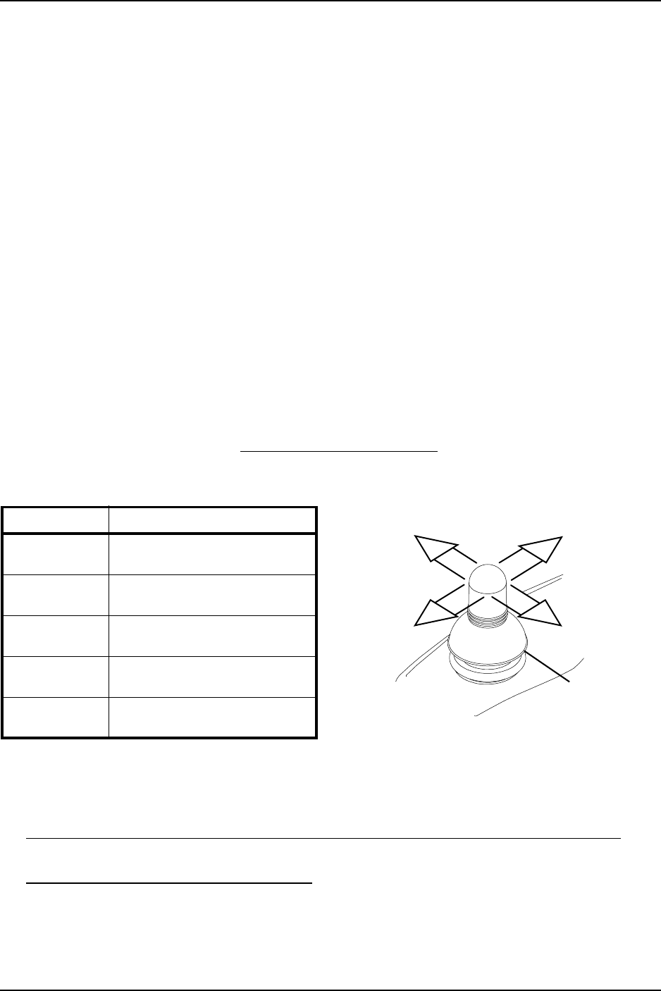
Using the Joystick to Drive the Wheelchair
NOTE:Forthisprocedure,refertoFIGURE 5.2.
Thejoystickislocatedonthejoystickhousingandprovidessmoothcontrolofspeedand
direction.Itisequippedwith360degreesofmobilityforeaseofoperation.Thejoystickis
spring‐loaded,andautomaticallyreturnstotheupright(neutral)positionwhenreleased.
Pushingthejoystickinagivendirectioncausesthewheelchairtomoveinthatdirection.
Thejoystickhasproportionaldrivecontrol,meaningthatthefurtheritispushedfromthe
upright(neutral)position,thefasterthewheelchairmoves.Themaximumspeed,
however,islimitedbythesettingofthespeed‐controlknob.
Toslowthewheelchairtoastop,simplyreleasethejoystick.Thewheelchairhas
automaticspeedanddirectioncompensationtominimizecorrections.
Whenfirstlearningtodrive,selectaslowspeedandtrytodrivethewheelchairasslowly
aspossiblebypushingthejoystickslightlyforward.Thisexercisewillhelpyoulearnto
utilizethefullpotentialoftheproportionalcontrolandallowyoutostartandstop
smoothly.
Todrivethewheelchair,performthefollowing:
1. Adjustspeedcontrolknobtotheappropriatesetting.
2. TurnthepowerOn.RefertoTurningthePowerOn/Offonpage 32.
3. Maneuverthejoystickinthefollowingmanner:
FIGURE 5.2 Using the Joystick to Drive the
Wheelchair
NOTE:Forspecificinformationaboutthejoystickinstalledonthewheelchair,refertooneofthese
procedures:
•SPJ+,MK6iSPJ+w/PSSandMK6iSPJ+w/ACCJoystickSwitchesandIndicatorson
page 34.
•MPJ+JoystickSwitchesandIndicatorsonpage 37.
MOVEMENT ACTION
FORWARD Push joystick forward, towards
the front of the wheelchair.
REVERSE Pull joystick back, towards the
rear of the wheelchair.
Turn RIGHT Move joystick toward the right
side of the wheelchair.
Turn LEFT Move joystick toward the left side
of the wheelchair.
STOP Release the joystick and the
wheelchair will slow to a stop.
To Move
Right
To Move
Forward
To Move
Left
To Move
Backward
Joystick
Front of
Wheelchair
Rear of
Wheelchair
SECTION 5—WHEELCHAIR OPERATION
Pronto® M91™Base with SureStep® 34 Part No 1143153
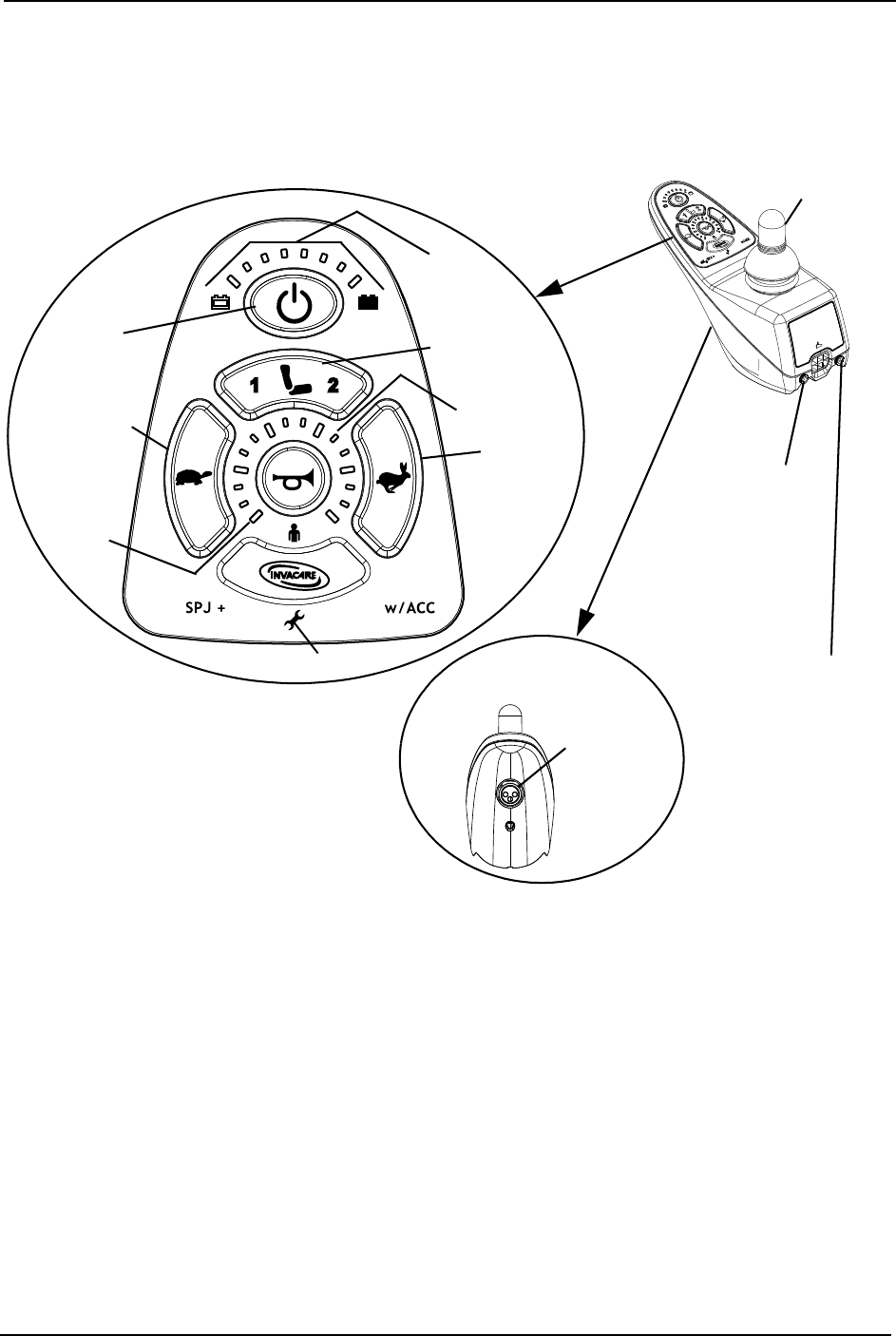
SPJ+, MK6i SPJ+ w/PSS and MK6i SPJ+ w/ACC Joystick
Switches and Indicators
NOTE:Forthefollowinginformation,refertoFIGURE 5.3.
FIGURE 5.3 SPJ+, MK6i SPJ+ w/PSS and MK6i SPJ+ w/ACC Joystick Switches and Indicators
On/Off Button
Thisbuttonislocatedatthefrontofthejoystickhousing.Itisusedtoturnthewheelchair
OnandOff,toremovethejoystickfromsleepmode(ifprogrammed)andtolockor
unlockthejoystick(ifprogrammed).
Speedometer
Thespeedometerisusedtoshowthemaximumspeed.Theright‐mostLEDindicates
currentmaximumspeedsetting.ThebottomleftGREENLEDflashestoindicatethatthe
joystickisinspeedlimitmode.Speedlimitmodelimitsthedrivespeedtoapre‐
programmedvalue,typicallywhentheseathasbeenelevatedandthewheelchairis
requiredtodriveat20%speed.
On/Off
Button
DETAIL “A” -
FRONT VIEW
Charger/
Programming
Input
Speedometer
Joystick
GREEN
LED
Information
Gauge
Display
Service Indicator
Decrease
Speed Button
(Tortoise) Increase
Speed Button
(Hare)
Mode Button*
Additional
Input for
Powered
Seating
Switch
*NOTE:Themodebuttonisonly
presentonSPJ+w/ACCjoystick.
Not Active

SECTION 5—WHEELCHAIR OPERATION
Part No 1143153 35 Pronto® M91™Base with SureStep®
Speed Control Buttons
Thespeedcontrolbuttons(tortoisebutton()andharebutton()areusedtosetand
adjustthemaximumspeed.
1. Toadjustthespeed,performoneofthefollowing:
•AdjustSpeedin20%Increments(5SpeedMode)‐Pressthetortoisebutton()
orharebutton()todecrease/increasethespeedin20%increments.Thelarger
barsinthespeedometerwilllight.
•AdjustSpeedinSmallerIncrements(VSPMode)‐Performthefollowingsteps:
i. Pressandholdboththetortoisebutton()andharebutton()untilthe
joystickbeeps.
ii. Performoneofthefollowing:
•Pressthetortoisebutton()orharebutton()todecrease/increasethe
speedin20%increments.Thelargerbarsinthespeedometerwilllight.
•Pressandholdthetortoisebutton()orharebutton()todecrease/
increasethespeedinsmallerincrements.Thesmallerbarsinthe
speedometerwilllight.
Joystick
Thejoystickhasproportionaldrivecontrol,meaningthatthefurtherthejoystickis
pushedfromtheupright(neutral)position,thefasterthewheelchairorseatmoves.Your
topspeed,however,islimitedbytheprogrammedsettings.
Toslowthewheelchairtoastop,simplyreleasethejoystick.Thewheelchairhas
automaticspeedanddirectioncompensationtominimizecorrections.
Charger/Programming Input
Thecharger/programminginputislocatedatthefrontofthejoystickhousing.This
provideseasyaccessforchargingthewheelchairbatteries.Thisportalsoservesasthe
RemoteProgrammerCommunicationconnection.Drivingispreventedwhilethesystem
ischarging.
Service Indicator
TheAMBERserviceindicatorwilllightwhenanerrororfaultoccurs.RefertoService
IndicatorLightDiagnosticsonpage 34foralistingoftheflashcodesandwhatthey
indicate.

SECTION 5—WHEELCHAIR OPERATION
Pronto® M91™Base with SureStep® 36 Part No 1143153
Information Gauge Display
Theinformationgaugedisplayislocatedonthefrontofthejoystickhousingandprovides
thefollowinginformationtotheuseronthestatusofthewheelchair:
1. PowerisOn.
2. Truestate‐of‐battery‐charge,includingnotificationofwhenthebatteryrequires
charging:
A. GREENLEDsarelit,indicatingwellchargedbatteries.
B. AMBERLEDsarelit,indicatingbatteriesaremoderatelycharged.Recharge
batteriesbeforetakingalongtrip.
C. REDLEDsarelit,indicatingbatteriesarerunningoutofcharge.Rechargebatteries
assoonaspossible.
TheInformationGaugedisplayalsoservesasasystemdiagnosticdevicewhenafaultis
detectedbythecontrolmodule.AspecificnumberofflashesoftheLEDsindicatethetype
offaultdetected.RefertoInformationGaugeDisplayDiagnosticsonpage 33forthe
diagnosticindicationsofthewheelchairstatus.

SECTION 5—WHEELCHAIR OPERATION
Part No 1143153 37 Pronto® M91™Base with SureStep®
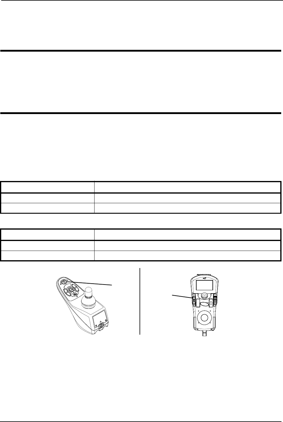
MPJ+ Joystick Switches and Indicators
NOTE:Forthisprocedure,refertoFIGURE 5.4.
Drive Select Toggle Switch
Thedriveselecttoggleswitchislocatedontheleftside,belowtheLCD.Thedriveselect
positionismomentary,meaningthatitwillreturntotheneutralpositionafteraselection
ismade.
Thisswitchallowstheoperatortoselectthetypeofoperationorperformancewhichbest
suitsaparticularcontrolneedorsituation.TheDRIVE1programusesperformance
valueswhichareindependentofthoseusedfortheDRIVE2or3or4program.Asan
example,anoperatormayhaveacontrolneedforspasticityinthemorningandavery
differentneedintheafternoon.DRIVE1canbeprogrammedforhigherspeedsand
quickerresponsewhileDRIVE2canbeprogrammedforslowerspeedsandless
responsivenessorviseversa.Theothertwodriveprogramscouldbeindoorandoutdoor
versionsofDRIVE1andDRIVE2.
Selecting the Drive Mode
1. Movethetoggleupandrelease.DRIVE1()willappearonLCD.
2. Movethetoggleupandreleaseagain.DRIVE2()willappearonLCD.
3. Movethetoggleupandreleaseagain.DRIVE3()willappearonLCD.
4. Movethetoggleupandreleaseagain.DRIVE4()willappearonLCD.
5. MovethetoggleupandreleaseonemoretimetoselectDRIVE1().
FIGURE 5.4 MPJ+ Joystick Switches and Indicators
Speed Control
Thespeedcontrolknobislocatedonthesideofthejoystickhousing.
1. Rotatetheknobclockwise(forward)toincreasethespeedofthewheelchairtothe
programmedmaxspeed.
Joystick
Remote
On/Off
Input
Programmable
Mono Port 1/2 or
External Mode
Switch
To Controller
Drive Select Toggle Switch
LCD Display
Speed Control Knob
Charger/Programming Input
(Front of Joystick)
Memory Card Slot
Mode Switch

SECTION 5—WHEELCHAIR OPERATION
Pronto® M91™Base with SureStep® 38 Part No 1143153
2. Rotatetheknobcounterclockwise(backward)todecreasethespeedofthewheelchair
totheprogrammedmaxspeed.
Joystick
Thejoystickhasproportionaldrivecontrol,meaningthatthefurtherthejoystickis
pushedfromtheupright(neutral)position,thefasterthewheelchairorseatmoves.Your
topspeed,however,islimitedbytheprogrammedsettings.
Toslowthewheelchairtoastop,simplyreleasethejoystick.Thewheelchairhas
automaticspeedanddirectioncompensationtominimizecorrections.
Charger/Programming Input
Thecharger/programminginputislocatedatthefrontofthejoystickhousing.This
provideseasyaccessforchargingthewheelchairbatteries.Thisportalsoservesasthe
RemoteProgrammerCommunicationconnection.Drivingispreventedwhilethesystem
ischarging.
LCD Display Screens
TheLCDDisplayislocatedinfrontofthejoystickandprovidesinformationonthestatus
ofthewheelchairthroughabacklitdisplay.TheLCDdisplayisreadableinbothbright
sunlightandcompletedarkness.
Splash Screen
NOTE:Forthisprocedure,referto
FIGURE 5.5.
Thisscreenisdisplayedatstartupofthe
joystickforabout2seconds.Thisscreen
displaysthesoftwareversionanddate
information.
Afterthisscreen,thejoystickdisplaysthe
MainScreen.
FIGURE 5.5 LCD Display Screens - Splash
Screen
Main Screen
NOTE:Forthisinformation,refertoFIGURE 5.6onpage 40.
Duringnormaloperation,theactivedriveisdisplayedintheupperhalfoftheLCD
display.BatterychargelevelisshownintheBatteryGaugeDisplay(BGD)locatedonthe
rightsideoftheLCDdisplay.Atfullcharge,solidblocksfillinalltensegmentsbetween
E(Empty)andF(Full).Asthebatterybecomesdischarged,thetopmostsegmentswill
progressivelydisappearuntilnosegmentsappearbetweenEandF.Atthislevel,theuser
shouldchargethebatteriesassoonaspossible.
ThelowerhalfoftheLCDdisplayistheInformationCenter.TheInformationCenter
displayscurrentdataonthewheelchair.
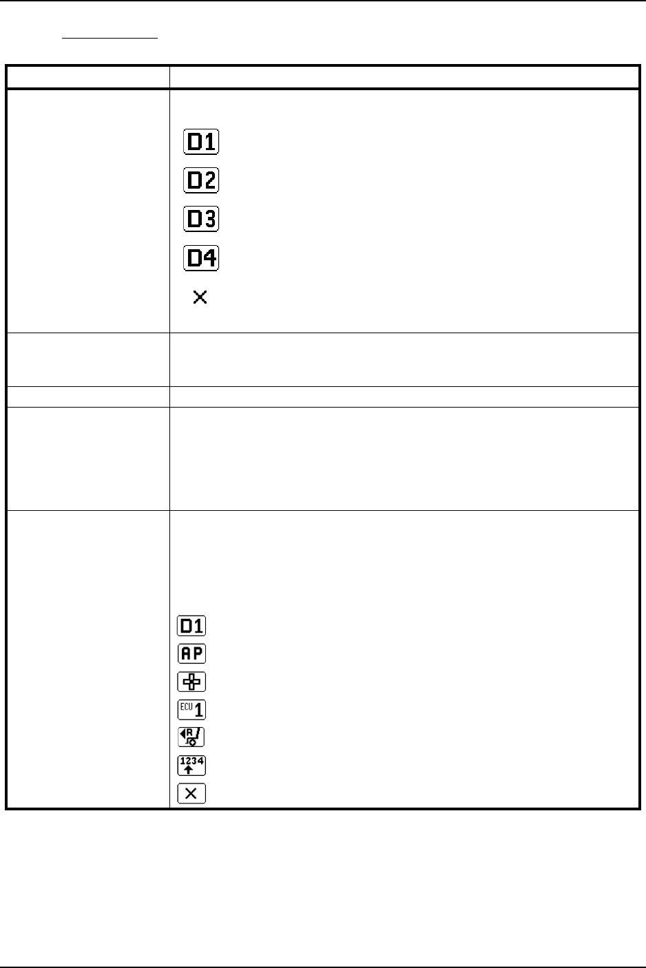
SECTION 5—WHEELCHAIR OPERATION
Part No 1143153 39 Pronto® M91™Base with SureStep®
RefertoLCDDisplaytableonpage 39fordescriptionsofinformationshown.
LCD DISPLAY
ITEM DESCRIPTION
DRIVE NAME This field shows the currently selected Drive’s Name.
Available choices are as follows:
Drive 1*
Drive 2*
Drive 3*
Drive 4*
“No Drive” selected via the programmer.
*NOTE: Drive names can be customized. Actual drive names may display differently.
BATTERY LEVEL
INDICATOR
This symbol shows the Battery Level and will change depending on the available
battery power.
This indicator is shown on every screen.
STATUS MESSAGE This area displays status or instructions.
STATUS INDICATOR The status indicator will show a “Warning” (exclamation point inside a triangle)
indicator when the chair has a condition that requires attention.
The status indicator will show a “STOP” sign when a serious condition exists. The
chair will not be allowed to operate.
The status indicator shows an Attendant Icon if the attendant’s override switch is
active.
MODES The dotted-box shows the area that contains the available “modes” in the cur-
rently selected drive. The modes are programmed for each drive and are based
upon the configuration of the chair.
These modes are highlighted when the Mode is active. The operator changes
modes by pressing the Mode Select Switch.
The available modes are as follows:
Drive Mode (1 through 4)
Automatic Positioning
Actuator Control Switch Mode (4-switch, 4-switch 2 levels, etc.)
ECU Output Activated (1 through 4)
RIM Mode Activated
Drive Select Mode Activated
No Driving
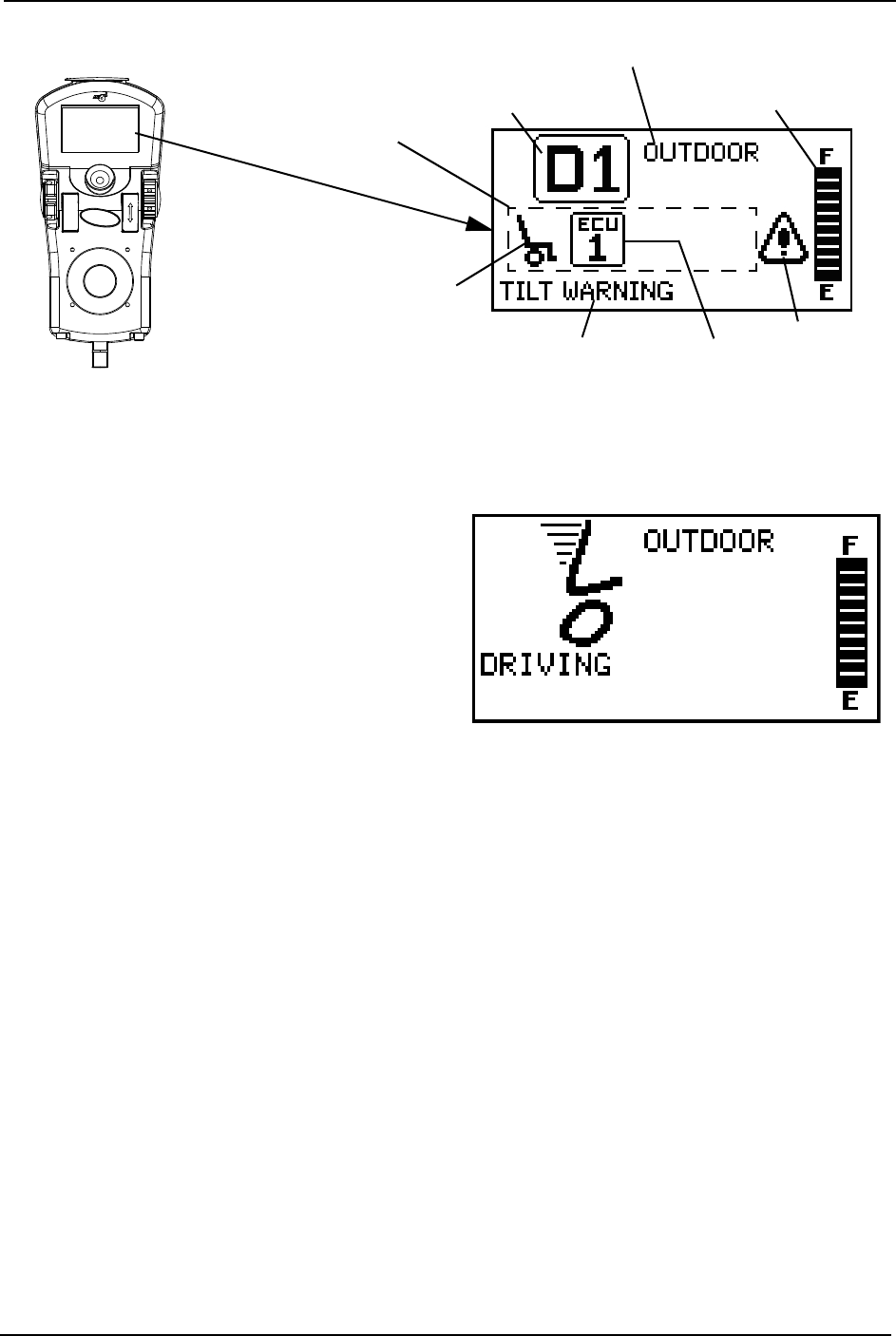
SECTION 5—WHEELCHAIR OPERATION
Pronto® M91™Base with SureStep® 40 Part No 1143153
FIGURE 5.6 LCD Display Screens - Main Screen
Driving Screen
NOTE:Forthisprocedure,referto
FIGURE 5.7.
Thisscreenisshownwhentheoperator
issuesadrivecommandandtheDriveIcon
onthemainscreenwashighlighted.
NOTE:TheDrive’sname,warning/info
message,statusiconandbatteryindicatorare
displayedonthisscreen.
FIGURE 5.7 LCD Display Screens - Driving
Screen
Connected Devices Screen
NOTE:Forthisprocedure,refertoFIGURE 5.8.
ThisscreenisdisplayediftheModeSelectswitchisheldactiveforabout10seconds.This
screenshowsaniconthatrepresentsanyadditionaldevicesthatareconnectedtothe
chair.
Available Modes in
this Drive (Must be
Programmed)
ECU
Drive Indicator
Icon appears when a
joystick command
will drive the
wheelchair
Battery Gauge Display
Status/Info
Message Area
Status
Indicator
Drive Profile Name
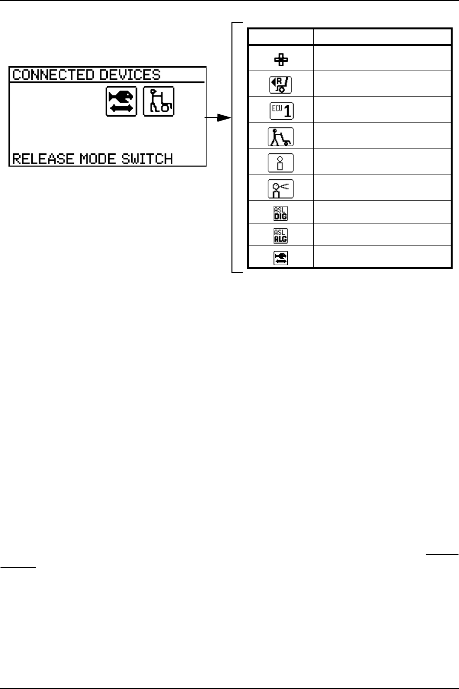
SECTION 5—WHEELCHAIR OPERATION
Part No 1143153 41 Pronto® M91™Base with SureStep®
FIGURE 5.8 LCD Display Screens - Connected Devices Screen
Programmable Mono Port 1/2 or External Mode Switch
Theprogrammablemonoportorexternalmodeswitchinputislocatedattherearofthe
joystickontheleftside.Theprogrammablemonoportinputoffersthechoiceofthree
options:
•Remotedriveselect
•Remotestop/mode(reset)input
•Singleactuatorinput
Thesingleswitchfunctionsoperatethroughmonoport1.Anoptionaly‐cableallowsa
secondprogrammablefunctionthroughmonoport2.
Remote Stop Switch
Theremotestopswitchisusedtostopthewheelchair.
Remote Mode (Reset) Switch
Theremotemoderesetswitchfunctionsthesamewayasthemodeswitch.RefertoMode
Switchonpage 42.
Remote On/Off Switch
TheremoteOn/Offswitchinputislocatedattherearofthejoystickontherightsideand
allowsthepowerswitchtobeoperatedbyanabilityswitch(normallyopenmomentary
switchwithmonoplug).TousetheremoteOn/Offfeature,theDriveSelect/On/Offswitch
mustbeintheOnposition.Eachactivationoftheabilityswitchwillalternatelyturnthe
joystickOnorOff.
ICON DESCRIPTION
4-Switch Attendant Control
RIM Control
ECU (1 to 4)
Proportional Attendant Control
Compact Joystick
Sip and Puff Control
ASL Digital Control
ASL Analog Control
Shark Power Module Actuator
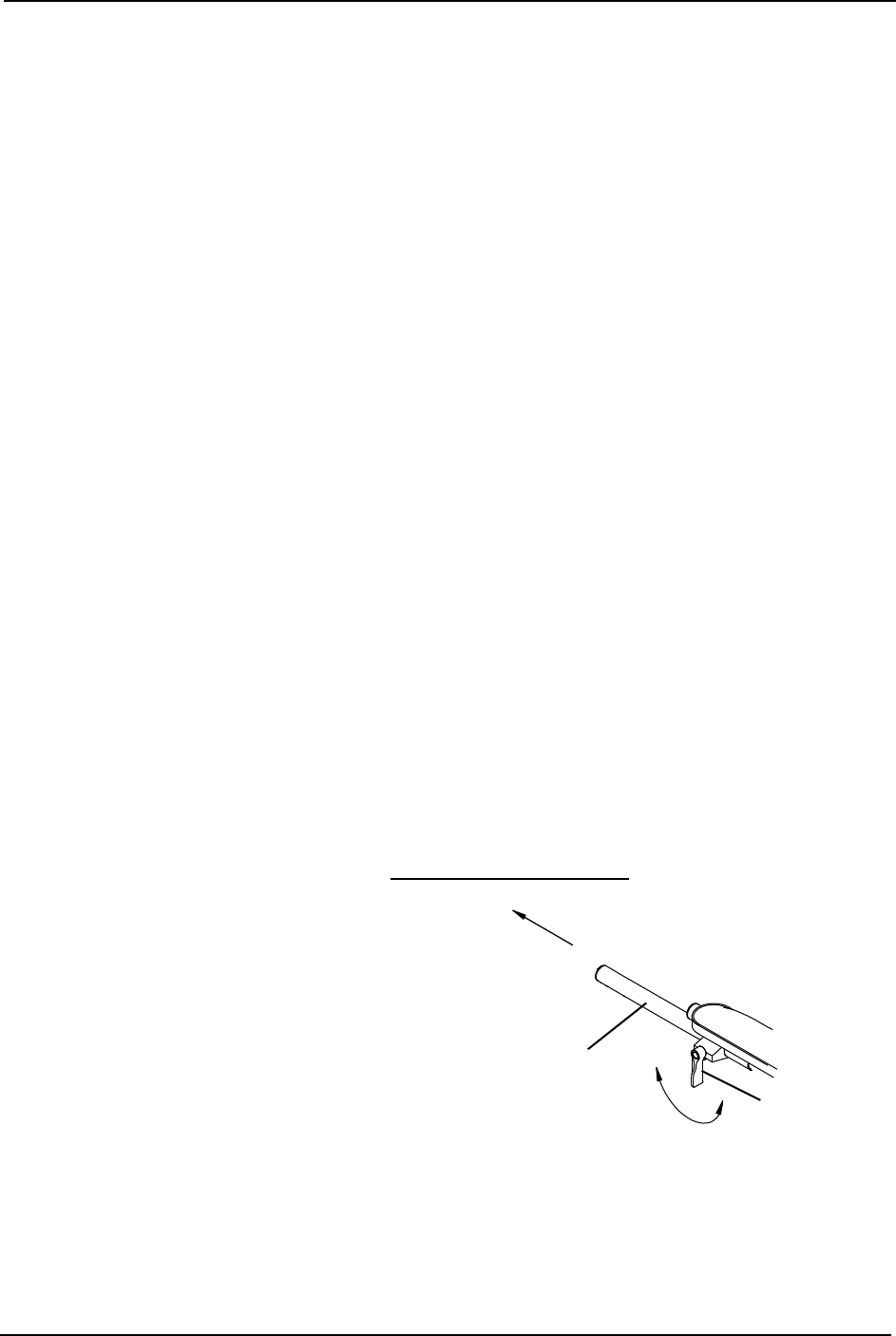
SECTION 5—WHEELCHAIR OPERATION
Pronto® M91™Base with SureStep® 42 Part No 1143153
Mode Switch
NOTE:Forthisprocedure,refertoFIGURE 5.4.
Themodeswitchisusedtoselecttheoperatingmodeforthewheelchair.Themode
switchislocatedonthejoystick.Amodeswitchisneededwheneveranyofthefollowing
operatingmodesareprogrammed:
• EnvironmentalControls(ECU1,ECU2,ECU3,ECU4)*
•3SpeedModeinDigital3Speed(Slow,Medium,Full)
•LatchedModes
•SleepMode
•RIMMode*
•RemoteDriveSelectionMode*
• Tilt/ReclineMode*
• InformationCenterDisplaySelection(doesnotrequireResetactivationatpowerup)
Ifanyoftheabovemodesareselected,thecontrolwillrequireactivationoftheswitch
immediatelyafterthepowerswitchisturnedOninordertoenterthedrivemode.The
secondlineoftheLCDwilldisplay‐PRESSRESET.
*NOTE:Inthesemodes,StandbySelectallowstheresetswitchtobebypassedforusersunableto
activatetheswitch.
Memory Card Slot
Thememorycardslotisusedwiththebasicorprofessionalmemorycardforsavingor
readingwheelchairparameters.
Preparing the Joystick for Use
NOTE:Forthisprocedure,refertoFIGURE 5.9.
NOTE:Thejoystickisfactoryinstalledontherightsideofthewheelchair.Torepositionthejoystick
ontotheleftsideofthewheelchair,refertoRepositioningtheJoystickonpage 43.
1. Turntheadjustmentlockleverto
releasetheadjustmentlockfrom
joystickmountingtube.
2. Slidejoystickmountingtubetothe
desiredposition.
3. Turntheadjustmentlockleverto
securetheadjustmentlocktothe
joystickmountingtube.
FIGURE 5.9 Preparing the Joystick for Use
NOTE:Joystick
notshown.
Joystick Mounting
Tube Adjustment
Lock Lever
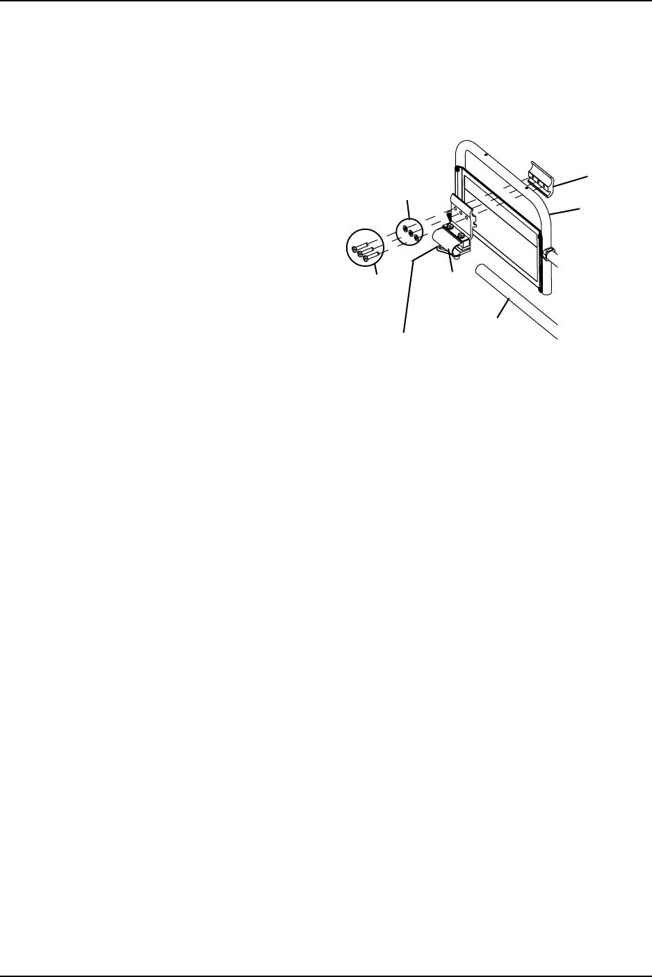
SECTION 5—WHEELCHAIR OPERATION
Part No 1143153 43 Pronto® M91™Base with SureStep®
Repositioning the Joystick
Adjustable ASBA Seat
NOTE:Forthisprocedure,refertoFIGURE 5.10.
1. Turntheadjustmentlockleverto
releasethejoystickmountingtubefrom
themountingbracket.
2. Removethejoystickfromthewheelchair.
3. Removethethreehexscrewsthat
securebothhalvesofthemounting
brackettothearmtube.
4. Repositionmountingbracketon
oppositearmtubeensuringthe
threadedplateofthemountingbracket
isontheinsideofthearmtubeas
showninFIGURE 5.10. FIGURE 5.10 Repositioning the Joystick
5. Usingthethreehexmountingscrewsandwashers,securebothhalvesofthemounting
brackettothearmtube.
6. Slidethejoystickmountingtubethroughthemountingbrackettothedesiredposition.
7. Turntheadjustmentlocklevertosecurethejoystickmountingtubeintothemounting
bracket.
Van Seat
NOTE:Forthisprocedure,refertoFIGURE 5.11.
NOTE:Takenoteofpositionandorientationofmountinghardwareforreinstallingthejoystick
assembly.
1. Turntheadjustmentlocklevertoreleasethejoystickmountingtubefromthe
mountingbracket.
2. Removethejoystickfromthewheelchair.
3. Removethethreehexmountingscrews,spacersandlocknutsthatsecurethe
mountingbrackettothethreemountingholesonthearmframe.
NOTE:Themountingbracketismountedtotheinsideofthearmframe.
4. Repositionthemountingbracketontheoppositearmframe.
5. Usingthethreehexmountingscrews,spacersandlocknutssecurethemounting
brackettothethreemountingholesofthearmframe.
Washers
Hex
Mounting
Screws
Mounting
Bracket
Adjustment
Lock Lever
Joystick
Mounting
Tube
Mounting Bracket
(Threaded Plate)
Arm
Tube
NOTE:
Joystick
not
shown.
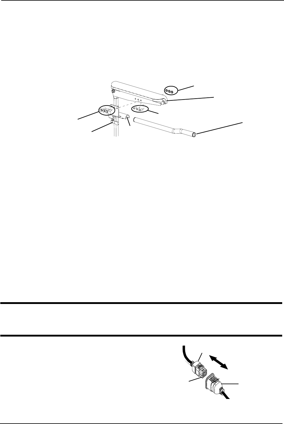
SECTION 5—WHEELCHAIR OPERATION
Pronto® M91™Base with SureStep® 44 Part No 1143153
6. Ifnecessary,performthefollowingtorepositiontheadjustmentlock:
A. Slidetheadjustmentlockfromthemountingbracket.
B. Rotateadjustmentlock180°andslideadjustmentlockovertheoppositeendofthe
mountingbracket.
7. Slidejoystickmountingtubethroughthemountingbrackettothedesiredposition
andsecureadjustmentlocktotubebyturningleveronadjustmentlock.
FIGURE 5.11 Repositioning the Joystick - Van Seat
Disconnecting/Connecting the Joysticks
NOTE:Forthisprocedure,refertoFIGURE 5.12.
NOTE:Thejoystickconnectorislocatedattherearoftheseatframe.
SPJ+ Joysticks
Disconnecting
1. HoldthelightGREYcollarportionofthejoystickconnectorwithonehandandthe
controllerconnectoronthewheelchairintheotheranddisconnectthembypulling
themapart.
Connecting
WARNING
The joystick connector and controller connector fit together in one way only. DO
NOT force them together.
1. HoldthelightGREYcollarportionof
thejoystickconnectorwithonehand
andthecontrollerconnectoronthe
wheelchairintheotherandalignthem.
2. Lightlypushtoengagethejoystick
connectorandthecontrollerconnector.
FIGURE 5.12 Disconnecting/Connecting
the Joysticks - SPJ+ Joysticks
Hex Mounting Screws
Locknuts
Adjustment Lock Lever
Joystick Mounting
Tube
Mounting
Bracket
Spacers
Arm Frame
NOTE:MK5SPJ‐80joystick
shown,allotherjoysticks
repositioninthesameway.
Joystick
Connector
Light Grey Collar
Controller
Connector

SECTION 5—WHEELCHAIR OPERATION
Part No 1143153 45 Pronto® M91™Base with SureStep®
MPJ+ Joysticks
NOTE:Forthisprocedure,refertoFIGURE 5.13.
Disconnecting
1. Pullthelatchawayfromthejoystickconnector.
2. Disconnectthejoystickconnectorfromtheremainingconnectors.
Connecting
1. Ensurethelatchispulledawayfromthejoystickconnector.
2. Connectthejoystickconnectortotheotherconnectors.
3. Pushthelatchintosecurethejoystickconnectortotheotherconnectors.
FIGURE 5.13 Disconnecting/Connecting the Joysticks - MPJ+ Joysticks
Joystick
Connector
Latch
Other Connectors

SECTION 6—SEAT
Pronto® M91™Base with SureStep® 46 Part No 1143153
SECTION 6—SEAT
WARNING
After any adjustments, repair or service and before use, make sure that all attaching
hardware is tightened securely - otherwise injury or damage may result.
Before performing any maintenance, adjustment or service verify that On/Off
switch on the joystick is in the Off position.
Removing/Installing the Seat Assembly
WARNING
DO NOT store items under seat - interference with seat latch may result.
NOTE:Forthisprocedure,refertoFIGURE 6.1onpage47.
NOTE:ThisprocedureisforwheelchairsWITHOUTtheFormulaPTOPlusseatingsystem
ONLY.ForwheelchairswiththeFormulaPTOPlusseatingsystem,refertoTiltingtheSeat
Assemblyonpage 47.
Removing
1. Disconnectthejoystick.RefertoDisconnecting/ConnectingtheJoysticksonpage 44.
2. Pushdownonthelatchbarunderneathfrontofseat.
3. Tiltfrontedgeofseatup.
4. Slidetheseatassemblyforwardtodisengageseatfromthepivotbracketslocatedin
therear.
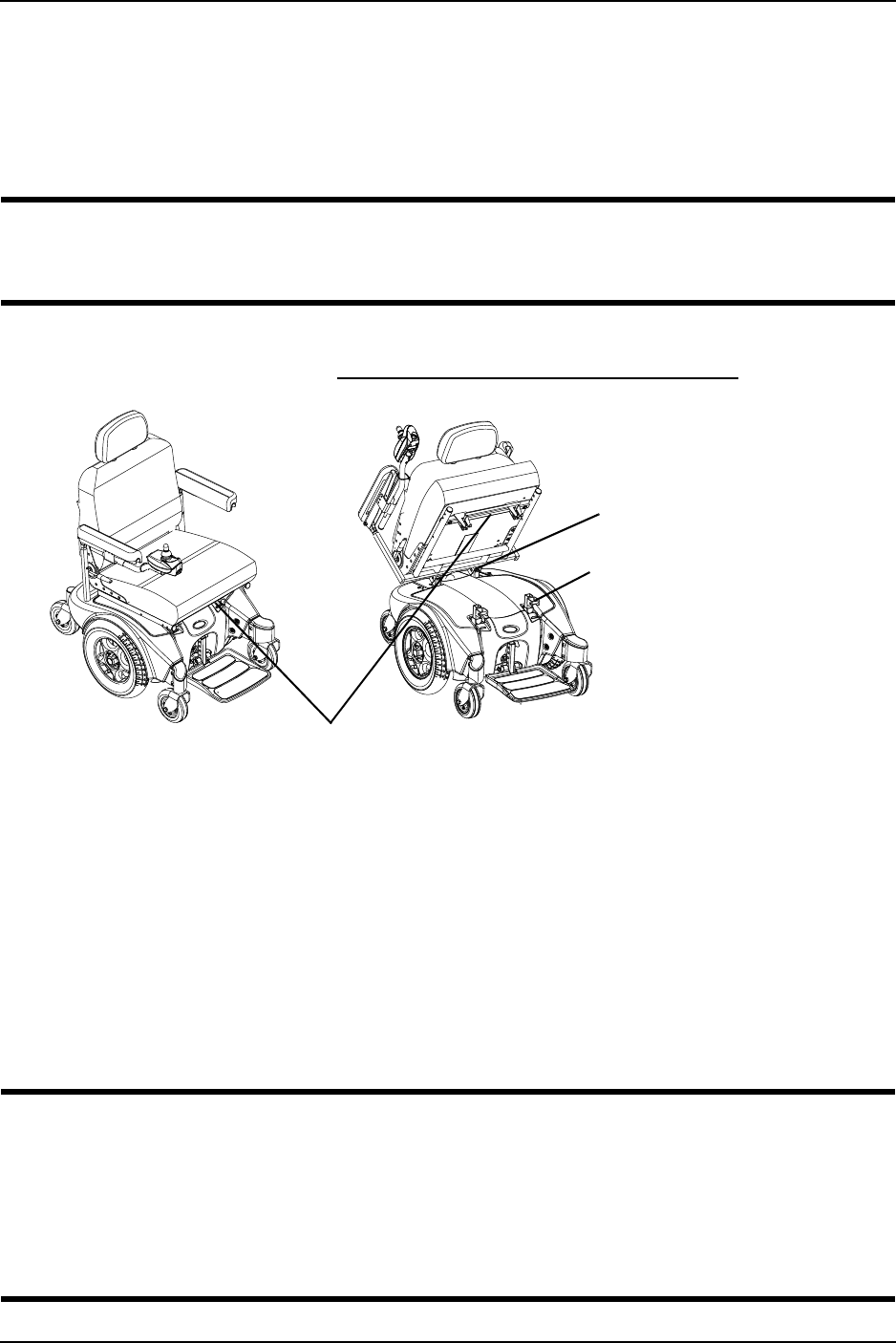
SECTION 6—SEAT
Part No 1143153 47 Pronto® M91™Base with SureStep®
Installing
1. PositiontheseatintherearpivotbracketsasshowninFIGURE 6.1.
2. Tiltfrontedgeofseatdown.
3. Whenseatislowered,engageseatbracketsintoseatclevispins.
WARNING
When reinstalling the seat verify that the seat brackets are engaged with the seat
clevis pins by pulling up on the latch bar.
4. Pulluponlatchbartoverifythatbracketsareengagedwithseatclevispins.
5. Connectthejoystick.RefertoDisconnecting/ConnectingtheJoysticksonpage 44.
FIGURE 6.1 Removing/Installing the Seat Assembly
Tilting the Seat Assembly
NOTE:Forthisprocedure,refertoFIGURE 6.2onpage48.
NOTE:ThisprocedureisforM91wheelchairswiththeFormulaPTOPlusSeatingSystemONLY.
NOTE:Removingtheseatisnotnecessarytoaccessthebatterycompartmentonwheelchairs
equippedwithaFormulaPTOPlusseatingsystem.TheseatassemblywiththeFormulaPTOPlus
seatingsystemtiltsbackandpropsintoplacetoprovideaccesstothebatteriesandtheunderside
oftheseat.
WARNING
Make sure power to the wheelchair is Off before performing this procedure.
Never leave the seat assembly in the up/open position unless necessary to perform a
procedure on the wheelchair - otherwise injury or damage may result.
After ANY adjustments, repair or service and before use, make sure all attaching
hardware is tightened securely - otherwise injury or damage may result.
Latch Bar
(located under the front of the seat)
NOTE:VanSeatmodel
shown.Adjustable
ASBAseatremoves/
installsinthesameway.
Rear Pivot
Brackets
Seat Clevis Pins
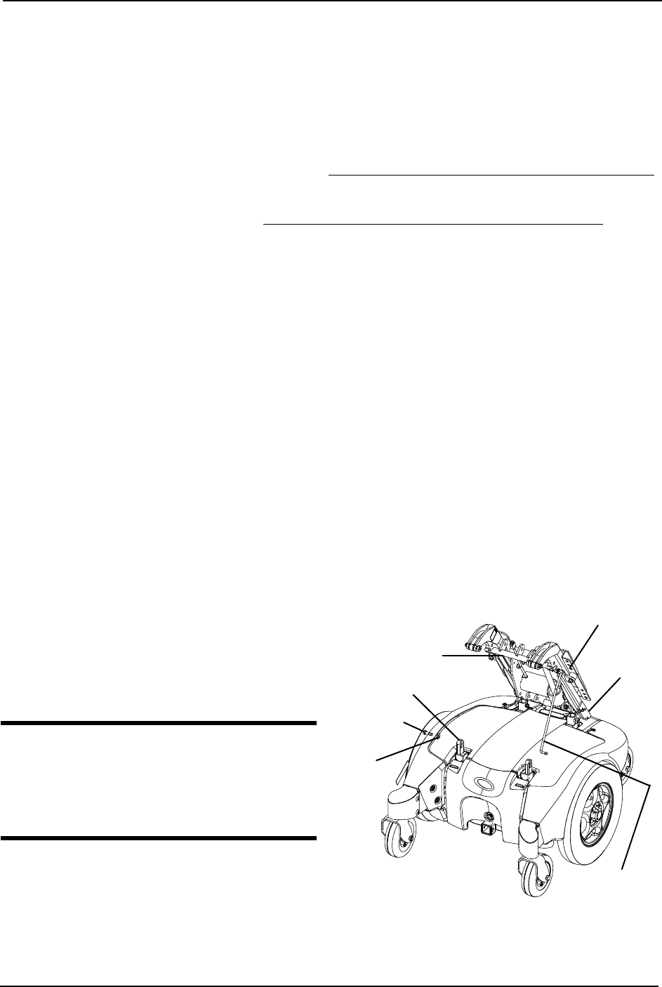
SECTION 6—SEAT
Pronto® M91™Base with SureStep® 48 Part No 1143153
Tilting the Seat Assembly Back
1. Placethewheelchairinawellventilatedareawhereworkcanbeperformedwithout
riskingdamagetocarpetingorfloorcovering.
2. Usethetiltfunctiontotilttheseatback20°to25°.
3. VerifythejoystickOn/OffswitchisintheOffpositionanddisconnectjoystickcable.
4. Engagethemotorreleaselevers.RefertoEngaging/DisengagingMotorReleaseLever
onpage 54.
5. Removethefootboard.RefertoRemoving/InstallingtheFootboardAssemblyon
page 49.
6. RemovethetwoscrewsandwasherssecuringtheFormulaPTOPlusframetothefront
seatposts.
7. Firmlygraspthefrontedgeoftheseatassembly,slowlytilttheseatassemblybackinto
theup/openposition.
8. RemoveproprodfromthecliplocatedontheFormulaPTOPlusframeandengage
theproprodendintothefrontseatpostasshowninFIGURE 6.2.
9. Gentlyallowweightofseatassemblytobesupportedbytheproprod.
NOTE:Onlyleavetheseatassemblyintheup/openpositionwhileperforminganynecessary
procedures.Alwayslowertheseatassemblytothedown/closedpositionwhennotservicingthe
wheelchairandensureitisinthelockedpositionbeforeusing.
Tilting the Seat Assembly Forward
1. Usingonehand,firmlygraspthefrontedgeoftheseatassemblyandliftuntilseat
assemblyisnolongersupportedbytheproprod.
2. Disengagetheproprodfromthefront
seatpostandsecureintoclip.
3. Usingbothhands,slowlytilttheseat
assemblyForwardintotheDown/
Closedposition.
WARNING
Ensure the two screws are fully engaged
and the Formula PTO Plus frame is
securely locked in place before use -
otherwise injury or damage may result.
4. Insertthetwoscrewsthroughthe
washers,theFormulaPTOPlusframe
andthetwofrontseatposts.
FIGURE 6.2 Tilting the Seat Assembly
Formula PTO
Plus Frame
Screw
Washer
Prop
Rod
Clip
Front Seat Post
Mounting Hole

SECTION 7—FOOTBOARD ASSEMBLY
Part No 1143153 49 Pronto® M91™Base with SureStep®
SECTION 7—FOOTBOARD
ASSEMBLY
WARNING
After any adjustments, repair or service and before use, make sure that all attaching
hardware is tightened securely - otherwise injury or damage may result.
Before performing any maintenance, adjustment or service verify that On/Off
switch on the joystick is in the Off position.
Pinch point may occur when rotating the footboard assembly.
DO NOT stand on the flip-up footboard. When getting in or out of the wheelchair,
make sure that the flip-up footboard is in the upward position.
LIMITED CLEARANCE BETWEEN FOOTBOARD AND CASTER - The user’s feet
MUST remain on the footboard while operating the wheelchair. If the user’s feet
are allowed to rest off the side of the footboard they may come in contact with the
caster possibly resulting in injury.
Removing/Installing the Footboard Assembly
NOTE:Forthisprocedure,refertoFIGURE 7.1onpage50.
Removing
1. Removethequickreleasepinthatsecuresthefootboardassemblytothewheelchair
framebydepressingthebuttonwhileslidingthepinout.
2. Removethefootboardassemblyfromthewheelchairframe.
Installing
WARNING
Make sure the detent balls of the quick release pin are fully released and protruding
past the outer edge of the tube before operating the wheelchair. Otherwise, injury
and/or damage may result.
Keep detent balls clean.
1. Positionthefootboardassemblyontothewheelchairframesothatthemountinghole
inthewheelchairframealignswiththedesiredmountingholeinthefootboard
assembly.
2. Installthequickreleasepinbydepressingthebuttonwhileslidingthepinin.Ensure
thatthedetentballsofthequickreleasepinarefullyreleasedandprotrudingpastthe
outeredgeofthetube(Detail“A”).
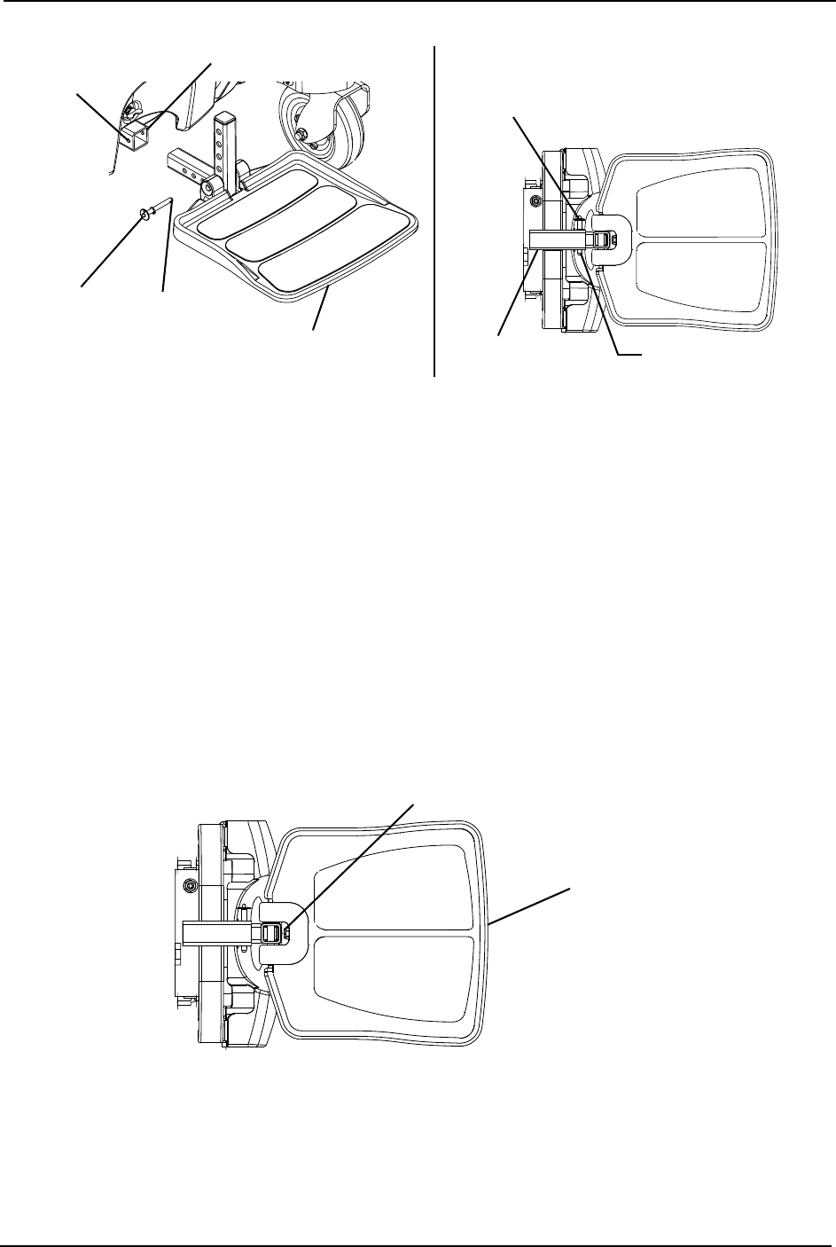
SECTION 7—FOOTBOARD ASSEMBLY
Pronto® M91™Base with SureStep® 50 Part No 1143153
FIGURE 7.1 Removing/Installing the Footboard Assembly
Adjusting the Footboard Assembly
Angle
NOTE:Forthisprocedure,refertoFIGURE 7.2.
1. Loosenthejamnutandsetscrewlocatedunderneathonthebackofthefootplate.
2. Adjustthesetscrewinorouttoobtainthedesiredfootboardassemblyangle.
3. Threadthejamnutandwasherinwarduntilitisflushwiththefootboardbracket.
4. Securelytightenthejamnutandwashertosecurethemountingscrewinplace.
FIGURE 7.2 Adjusting the Footboard Assembly - Angle
DETAIL “A” - BOTTOM
VIEW OF FOOTBOARD
Quick
Release Pin
Outer Edge
of Tube Detent Balls
Quick
Release
Pin
Wheelchair Frame
Detent
Ball
Footboard
Assembly
Mounting
Hole
Set Screw, Washer
and Jam Nut
Footboard
Assembly
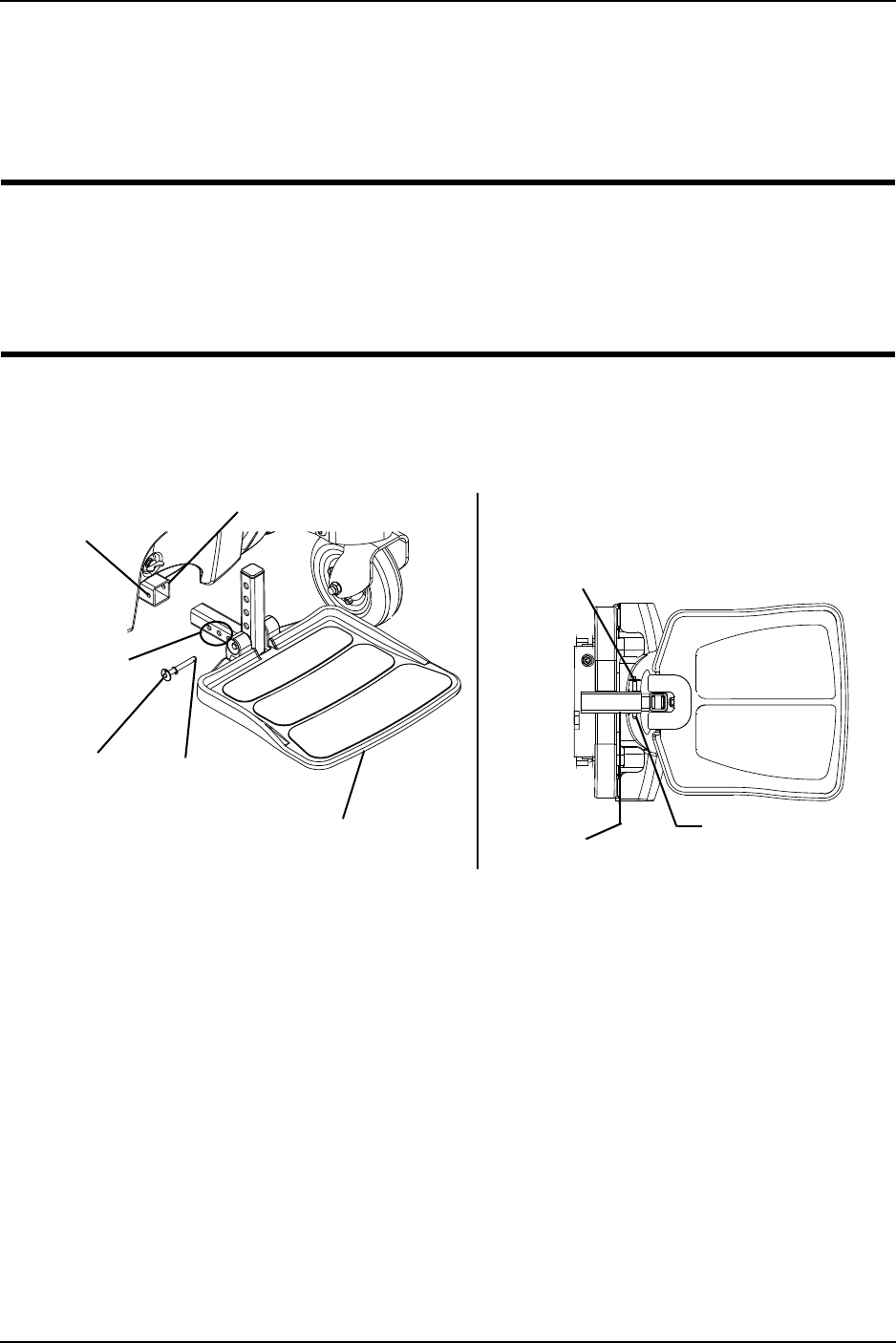
SECTION 7—FOOTBOARD ASSEMBLY
Part No 1143153 51 Pronto® M91™Base with SureStep®
Depth
NOTE:Forthisprocedure,refertoFIGURE 7.3.
1. Removethequickreleasepinthatsecuresthefootboardassemblytothewheelchair
frame.
WARNING
Make sure the detent balls of the quick release pin are fully released and protruding
past the outer edge of the tube before operating the wheelchair. Otherwise, injury
and/or damage may result.
Keep detent balls clean.
2. Adjustfootboardtooneofthreemountingpositions.
3. Installthequickreleasepin.Makesurethedetentballsofthequickreleasepinare
fullyreleasedandpasttheouteredgeofthetube(Detail“A”).
FIGURE 7.3 Adjusting the Footboard Assembly - Depth
DETAIL “A” - BOTTOM
VIEW OF FOOTBOARD
Quick Release Pin
Outer Edge
of Tube Detent Balls
Quick
Release
Pin
Three
Depth
Adjustment
Holes
Wheelchair Frame
Detent
Ball
Footboard
Assembly
Mounting
Hole

SECTION 8—SHROUD/WHEELS
Pronto® M91™Base with SureStep® 52 Part No 1143153
SECTION 8—SHROUD/WHEELS
WARNING
After any adjustments, repair or service and before use, make sure that all attaching
hardware is tightened securely - otherwise injury or damage may result.
Before performing any maintenance, adjustment or service verify that On/Off
switch on the joystick is in the Off position.
Replacing the Flat Free Tires on the Wheel Rim
WARNING
DO NOT attempt to replace flat free tires. This procedure MUST be performed by
a qualified technician.
NOTE:Duringinitialuseofthewheelchair,theusermayexperienceflatspotsonthewheels.Flat
spotswillvanishwithcontinueduseofthewheelchair.
Removing/Installing the Shrouds
NOTE:Forthisprocedure,refertoFIGURE 8.1onpage53.
Removing
1. Performoneofthefollowing:
• WheelchairswithFormulaPTOPlus‐Tilttheseatback.RefertoTiltingtheSeat
Assemblyonpage 47.
• WheelchairswithoutFormulaPTOPlus‐Removetheseatassembly.Referto
Removing/InstallingtheSeatAssemblyonpage 46.
2. Performoneofthefollowing:
•TopShroud‐Liftuponrearedgeoftopshroudtoreleasethefourhookandloop
stripsthatsecurethetopshroudtothebaseframe(Detail“A”).
•FrontShroud‐Turnreleaseknob¼‐turntotheunlockedpositionandliftupto
removefrontshroudfrombaseframehooks(Detail“B”).
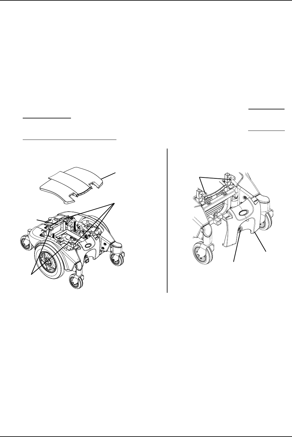
SECTION 8—SHROUD/WHEELS
Part No 1143153 53 Pronto® M91™Base with SureStep®
Installing
1. Performoneofthefollowing:
•TopShroud‐Positiontopshroudontothebaseframeandgentlypressdownon
topshroudtosecurethefourhookandloopstripsthatsecurethetopshroudtothe
baseframe(Detail“A”).
•FrontShroud‐Positionfrontshroudontothetwobaseframehooks.Turnrelease
knob¼‐turntothelockedposition(Detail“B”).
2. Performoneofthefollowing:
• WheelchairswithFormulaPTOPlus‐Tilttheseatforward.RefertoTiltingthe
SeatAssemblyonpage 47.
• WheelchairswithoutFormulaPTOPlus‐Reinstalltheseat.RefertoRemoving/
InstallingtheSeatAssemblyonpage 46.
FIGURE 8.1 Removing/Installing the Shrouds
DETAIL “B” - FRONT SHROUD
DETAIL “A” - TOP SHROUD
Top Shroud
Rear of
Wheelchair
Front of
Wheelchair
Seat Supports
Hook and
Loop Strips
Base Frame
Release
Knob
Front
Shroud
Base
Frame
Hooks

SECTION 8—SHROUD/WHEELS
Pronto® M91™Base with SureStep® 54 Part No 1143153
Engaging/Disengaging Motor Release Lever
WARNING
DO NOT engage or disengage the motor release lever until the On/Off switch on
the joystick is in the Off position.
CAUTION
Ensure both motor release levers are fully engaged before driving the wheelchair
NOTE:Forthisprocedure,refertoFIGURE 8.2.
NOTE:Themotorlockdisengagement/engagementallowsfreewheelingorjoystickcontrolled
operation.Freewheelingallowsanattendanttomaneuverthewheelchairwithoutpower.
1. Locatethemotorreleasehandlesonthemotorsprotrudingthroughtheshroudsby
therearsprings.
2. Performoneofthefollowing:
•Todisengagethemotorreleaselevers‐Slidethemotorlocklevertowardsthe
outsideofthewheelchair(freewheelposition)(Detail“A”).
NOTE:Thisallowsthewheelchairtofreewheelforpushingifnecessary
•Toengagethemotorreleaselevers‐Slidethemotorlockhandlestowardsthe
centerofthewheelchair(driveposition)(Detail“A”).
NOTE:Thisallowsthemotorstodrivethewheels.
FIGURE 8.2 Engaging/Disengaging Motor Release Lever
DETAIL “A”
Motor Locks Disengaged
(Freewheel Mode)
Motor Locks Engaged
(Drive Mode)
Towards
Outside of
Wheelchair
Towards Center
of Wheelchair
Motor
Release
Lever

SECTION 8—SHROUD/WHEELS
Part No 1143153 55 Pronto® M91™Base with SureStep®
Replacing Front/Rear Caster Assemblies
NOTE:Forthisprocedure,referto
FIGURE 8.3.
NOTE:Frontandrearcasterassembliesare
replacedinthesamemanner.
NOTE:Whenreplacingthefront/rearcaster
assemblies,itisnecessarytobracethecaster
assembliestopreventthewheelfromspinning.
1. Removethemountingscrew,two
washers,andlocknutthatsecuresthe
castertothefork.
2. Removethecasteranddiscard.
FIGURE 8.3 Replacing Front/Rear Caster
Assemblies
3. Securenewcastertoforkwithexistingmountingscrew,twowashersandlocknut
(FIGURE 8.3).Securelytighten.
Adjusting Forks
NOTE:Forthisprocedure,refertoFIGURE 8.4.
1. Removethedustcover.
2. Toproperlytightencasterjournal
systemandguardagainstflutter,
performthefollowingcheck:
A. Tipbackthewheelchair.
B. Pivotbothforksandcasterstotop
oftheirarcsimultaneously.
C. Letcastersdroptobottomofarc
(wheelsshouldswingoncetoone‐
side,thenIMMEDIATELYrestina
straightdownwardposition).
D. Adjustlocknutsaccordingto
freedomofcasterswing.
3. Testwheelchairformaneuverability.
4. Readjustlocknutsifnecessary,and
repeatSTEPS1‐3untilcorrect. FIGURE 8.4 Adjusting Forks
5. Snapdustcoverintothecasterheadtubeensuringthatthetabsareundertheplastic
sideshrouds.
NOTE:Componentsexplodedforclarity.Thereisnoneedtoremovetheforkfromthebaseframe.
Washer
Mounting
Screw
Caster
Locknut
Washer
Fork
Base
Frame
Tabs
Locknut
Dust
Cover
Washer
Side
Shroud
Caster
Headtube
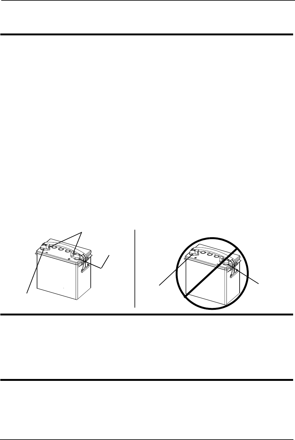
SECTION 9—BATTERIES
Pronto® M91™Base with SureStep® 56 Part No 1143153
SECTION 9—BATTERIES
WARNING
Make sure power to the wheelchair is Off before performing this section.
NEVER allow any of your tools and/or battery cable(s) to contact both battery
terminal(s)/post(s) at the same time. An electrical short may occur and serious
personal injury or damage may occur.
The use of rubber gloves is recommended when working with batteries.
Always use a battery lifting strap when lifting a battery. It is the most convenient
method and assures that the battery acid will not spill. It also helps to prolong the
life of the battery.
DO NOT tip the batteries. Keep the batteries in an upright position.
Avoid storage or use near external flame or combustible products.
Invacare strongly recommends that battery installation and battery replacement
always be done by a qualified technician.
After any adjustments, repair or service and before use, make sure all attaching
hardware is tightened securely - otherwise injury or damage may result.
Battery terminal configuration shown below MUST be used. Batteries that have the
reversed terminal configuration MUST NOT be used - otherwise serious injury or
damage may occur.
CAUTION
When connecting the battery cables to the battery(ies), the battery cable(s) MUST
be connected to the battery terminal(s)/post(s) as shown in FIGURE 9.3 otherwise
damage to the battery may result.
For proper battery connection, batteries MUST use post style terminals with
mounting holes through the terminal.
NOTE:Ifthereisbatteryacidinthebottomofthebatterytrayoronthesidesofthebattery(ies),
applybakingsodatotheseareastoneutralizethebatteryacid.Beforereinstallingtheexistingor
newbattery(ies),cleanthebakingsodafromthebatterytrayorbattery(ies)beingsuretoavoid
contactwithskinandeyes.Determinesourceofcontamination.NEVERinstall/reinstallabattery
withacrackedorotherwisedamagedcase.
NEGATIVE (-)
Battery Terminal
POSITIVE
(+) Battery
Terminal
POSITIVE
(+) Battery
Terminal
NEGATIVE
(-) Battery
Terminal
DO NOT Use
Mounting Holes

SECTION 9—BATTERIES
Part No 1143153 57 Pronto® M91™Base with SureStep®
Installing/Removing the Batteries
NOTE:Forthisprocedure,refertoFIGURE 9.1onpage58andFIGURE 9.2onpage59.
NOTE:Havethefollowingtoolsavailable:
Installing
1. Placethewheelchairinawellventilatedareawhereworkcanbeperformedwithout
riskingdamagetocarpetingorfloorcovering.
2. VerifythejoystickOn/OffswitchisintheOffpositionanddisconnectjoystick.Refer
toDisconnecting/ConnectingtheJoysticksonpage 44.
3. Performoneofthefollowing:
• WheelchairswithoutFormulaPTOPlus‐Removetheseat.RefertoRemoving/
InstallingtheSeatAssemblyonpage 46.
• WheelchairswithFormulaPTOPlus‐Tilttheseatback.RefertoTiltingtheSeat
Assemblyonpage 47.
4. Removethetopshroud.RefertoRemoving/InstallingtheShroudsonpage 52.
5. Ifnecessary,disconnectrightandleftmotorleadstoallowaccesstothefrontofthe
batterytray.
6. Moveasidethemotorleadsandcontrollercabletoallowunobstructedaccesstothe
frontofthebatterytray.
NOTE:Performthissectionononebatteryatatimestartingwiththerearbattery.RepeatSTEP
6topositiontheremainingbatteryintothebatterytray.
7. Performoneofthefollowingtopositionthebatteryintothebatterytray:
• BatteriesWithBuiltInLiftingStrap‐Usebuiltinliftingstraptopositionbattery
intothebatterytray(Detail“A ” ofFIGURE 9.1).
• BatteriesWithoutBuiltInLiftingStrap‐Usethebatteryliftingstraptoposition
batteryintothebatterytray.Whenbatteryisinproperposition,removelifting
strap(Detail“B”ofFIGURE 9.1).
8. Usingthebatteryretainingstrap,securethetwobatteriesintothebatterytray.
TOOL QTY COMMENTS
Battery Lifting Strap 1 Supplied
1/2-inch (6 pt) Box Wrench 1 Not Supplied
7/16-inch (6pt) Box Wrench 1 Not Supplied
3/8-inch (6pt) Box Wrench 1 Not Supplied
Diagonal Cutters 1 Not Supplied
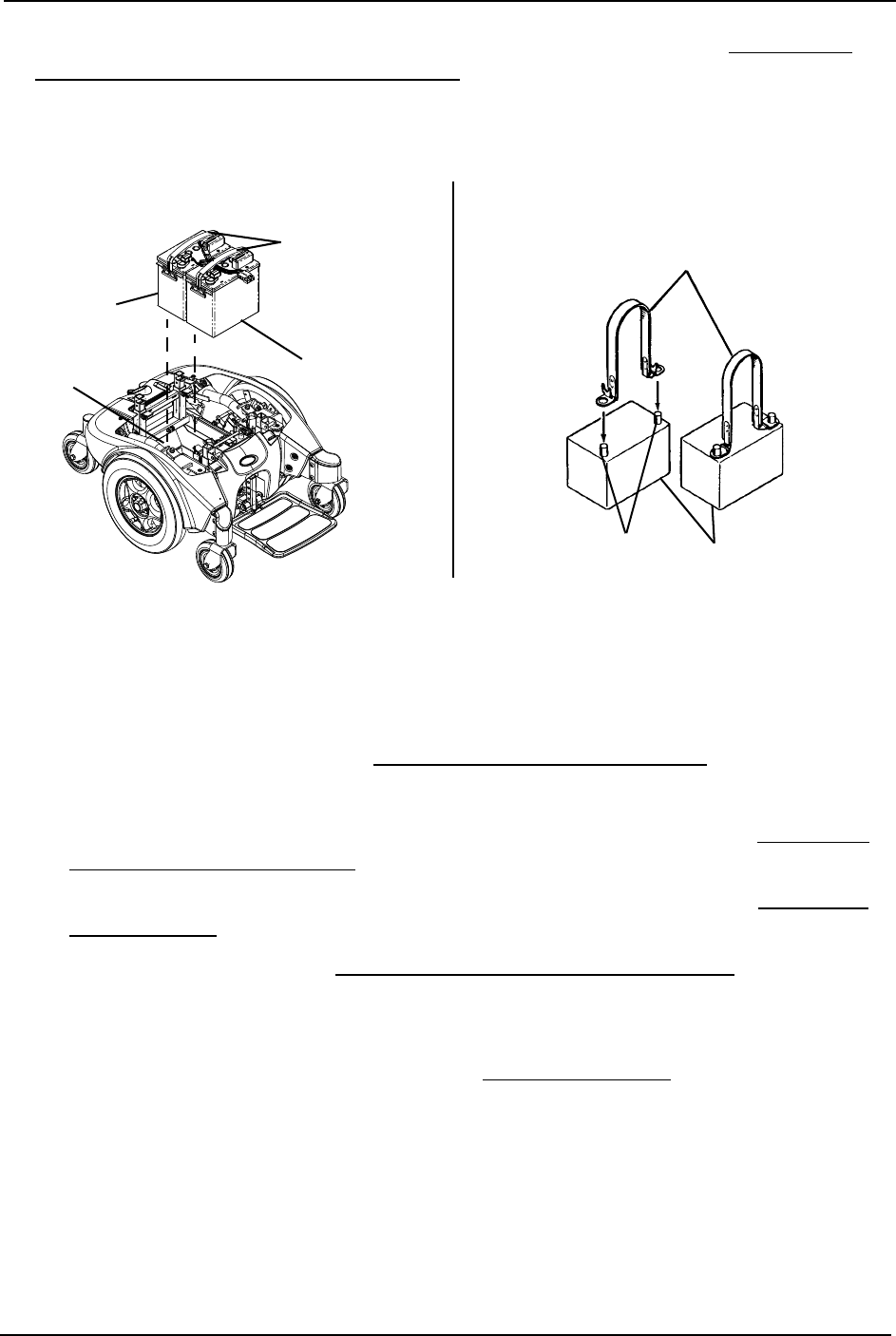
SECTION 9—BATTERIES
Pronto® M91™Base with SureStep® 58 Part No 1143153
9. Ifnecessary,connectthewiringharnesstothetwobatteries.RefertoConnecting/
DisconnectingtheBatteryWiringHarnessonpage 60.
10. ReconnectRIGHTandLEFTmotorleadstoallowaccesstotheFRONTofthebattery
tray,ifdisconnectedinSTEP5.
FIGURE 9.1 Batteries with/without Lifting straps
11. Connectthefrontbatterytothecontroller(REDconnector).RefertoFIGURE 9.2.
12. Connecttherearbatterytothefrontbattery(REDandBLACKconnectors).Referto
FIGURE 9.2.
13. Reinstallthetopshroud.RefertoRemoving/InstallingtheShroudsonpage 52.
14. Performoneofthefollowing:
• WheelchairswithoutFormulaPTOPlus‐Reinstalltheseat.RefertoRemoving/
InstallingtheSeatAssemblyonpage 46.
• WheelchairswithFormulaPTOPlus‐Tilttheseatforward.RefertoTiltingthe
SeatAssemblyonpage 47.
15. Connectthejoystick.RefertoDisconnecting/ConnectingtheJoysticksonpage 44.
NOTE:Newbattery(ies)MUSTbefullychargedbeforeusing,otherwisethelifeofthebattery(ies)
willbereduced.
16. Ifnecessary,chargethebattery(ies).RefertoChargingBatteriesonpage 63.
Battery Lifting Straps
Battery
Terminals/Posts Battery
DETAIL “B” - BATTERIES WITHOUT
BUILT-IN LIFTING STRAPS
DETAIL “A” - BATTERIES WITH
BUILT-IN LIFTING STRAPS
Built-in Lifting
Straps
Front
Battery
Rear
Battery
Battery
Tray
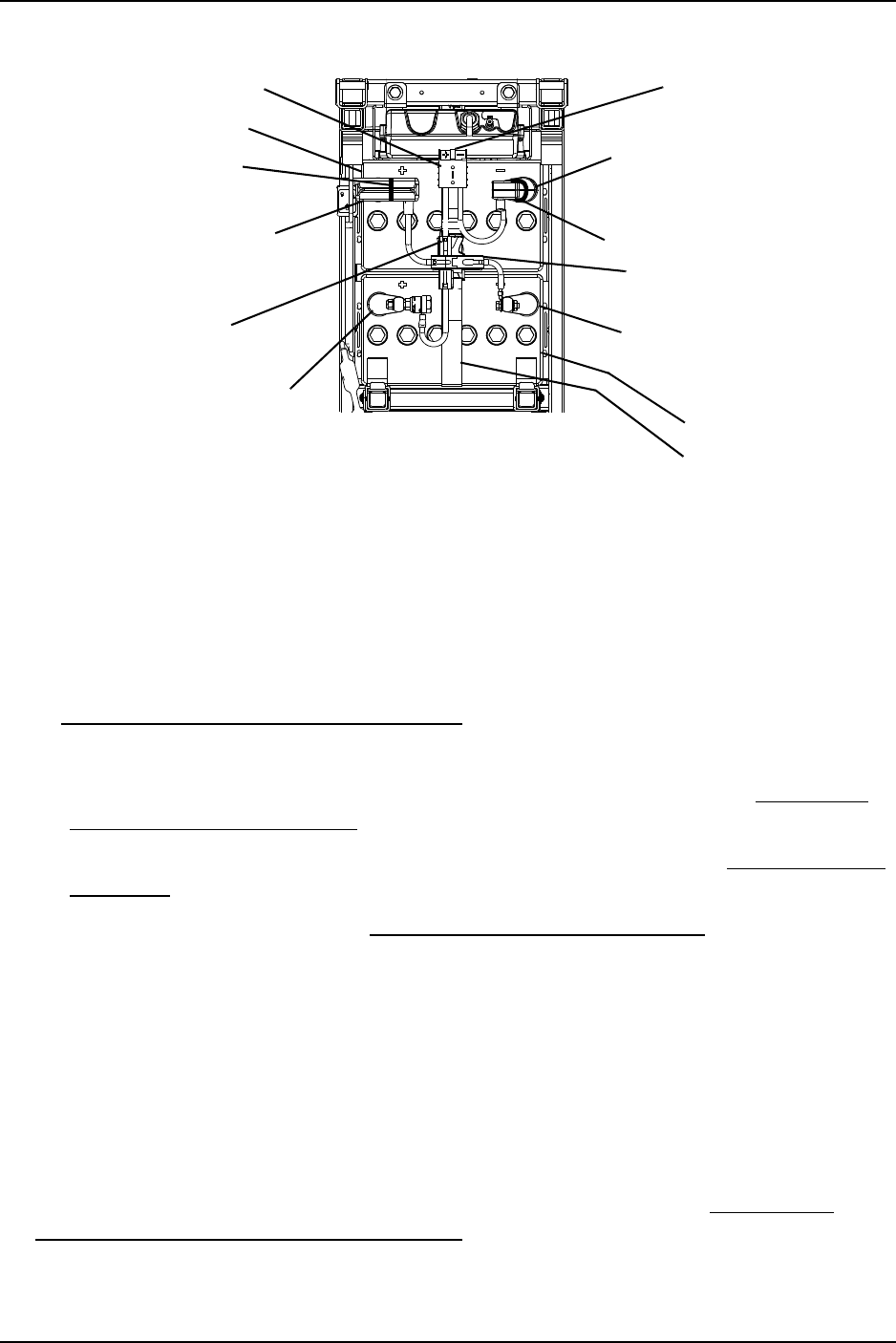
SECTION 9—BATTERIES
Part No 1143153 59 Pronto® M91™Base with SureStep®
FIGURE 9.2 Installing/Removing the Batteries
Removing
1. Placethewheelchairinawellventilatedareawhereworkcanbeperformedwithout
riskingdamagetocarpetingorfloorcovering.
2. VerifythejoystickOn/OffswitchisintheOffpositionanddisconnectjoystick.Refer
toDisconnecting/ConnectingtheJoysticksonpage 44.
3. Performoneofthefollowing:
• WheelchairswithoutFormulaPTOPlus‐Removetheseat.RefertoRemoving/
InstallingtheSeatAssemblyonpage 46.
• WheelchairswithFormulaPTOPlus‐Tilttheseatback.RefertoTiltingtheSeat
Assemblyonpage 47.
4. Removethetopshroud.RefertoRemoving/InstallingtheShroudsonpage 52.
5. Ifnecessary,disconnectrightandleftmotorleadstoallowaccesstothefrontofthe
batterytray.
6. Disconnectthefrontbatteryfromcontroller(REDconnector).RefertoFIGURE 9.2.
7. Moveasidethemotorleadsandcontrollercabletoallowunobstructedaccesstothe
frontofthebatterytray.
8. Disconnecttherearbatteryfromthefrontbattery(REDandBLACKconnectors).Refer
toFIGURE 9.2.
9. Ifnecessary,disconnectthewiringharnessfrombatteries.RefertoConnecting/
DisconnectingtheBatteryWiringHarnessonpage 60.
10. Unfastentheretainingstrapthatsecuresthetwobatteriesinthebatterytray.
Front of Wheelchair
Rear of wheelchair
RED Connector from
Battery to Controller
Front Battery
RED Front POSITIVE (+)
Battery Terminal Mounting
Screw, Nut and Fuse Hardware
(Terminal Cap Shown)
RED Rear POSITIVE (+) Battery
Terminal Mounting Screw, Nut
and Fuse Hardware*
RED Controller Connector
(Not Shown)
Rear Battery
BLACK Front NEGATIVE (-)
Battery Terminal Mounting
Screw, Nut and Fuse Hardware
(Terminal Cap Shown)
BLACK Battery Connectors
GREY Rear NEGATIVE (-)
Battery Terminal Mounting
Screw, Nut and Fuse Hardware*
Retaining Strap
*NOTE:Terminalcapshownremovedforclarity.
RED Battery Connectors
Tie Wrap
Tie Wrap

SECTION 9—BATTERIES
Pronto® M91™Base with SureStep® 60 Part No 1143153
NOTE:PerformthissectionononebatteryatatimestartingwiththeFRONTbattery.Repeat
STEP10toremoveremainingbatteryfrombatterytray.
11. Performoneofthefollowingtoremovethebatteryfromthebatterytray:
• BatteriesWithBuilt‐inLiftingStrap‐Usebuiltinliftingstraptoremovethebattery
fromthebatterytray(Detail“A ” ofFIGURE 9.1).
• BatteriesWithoutBuilt‐inLiftingStrap‐Usethebatteryliftingstraptoremovethe
batteryfromthebatterytray(Detail“B”ofFIGURE 9.1).
Connecting/Disconnecting the Battery Wiring Harness
NOTE:Performthissectionononebatteryatatimestartingwiththefrontbattery.
NOTE:Thefrontbatteryhasthreeconnectors‐twototherearbatterywiringharness(REDand
BLACK)andonetothecontrollercable(RED),andtherearbatteryhastwoconnectors(REDand
BLACK)tothefrontbatterywiringharness.
NOTE:BoththefrontandrearwiringharnessesareshippedwiththePOSITIVE(+)REDbattery
cableandmountingscrewconnected.Usetheexposed,threadedportionofthemountingscrewto
securethePOSITIVE(+)REDcabletothePOSITIVE(+)terminal.
WARNING
DO NOT remove fuse or mounting hardware from POSITIVE (+) RED battery
cable/mounting screw.
All battery terminal covers (two on the front battery and two on the rear battery)
MUST be installed prior to use.
Connecting
NOTE:Forthisprocedure,refertoFIGURE 9.3onpage61.
1. PeelbackREDbatteryterminalcovertoexposeREDbatterycableconnectionto
batteryterminal.
2. PeelbackBLACKbatteryterminalcoverfromBLACKbatterycableonfrontbattery
orGREYbatteryterminalcoverfromBLACKbatterycableonrearbattery.
3. Usingthemountingscrewsandnuts,securetheNEGATIVE(‐)BLACKbatterycable
toNEGATIVE(‐)batteryterminal/postasshowninFIGURE 9.3.
4. Usingthemountingscrewsandnuts,securethePOSITIVE(+)REDbatterycableto
POSITIVE(+)batteryterminal/postasshowninFIGURE 9.3.
5. Verifywiringharnessiscorrectlyinstalledandsecurelytightened.
6. Verifyproperbatteryorientation.
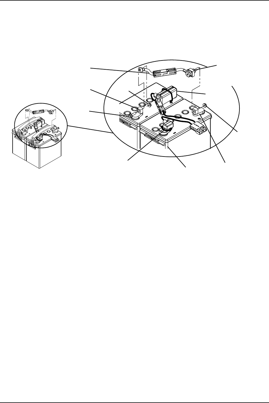
SECTION 9—BATTERIES
Part No 1143153 61 Pronto® M91™Base with SureStep®
7. Repositionbatteryterminalcoversoverbatterypost(s).
8. Usingnewtie‐wraps,securetheterminalcoverstothebatteryterminalsasshownin
FIGURE 9.3.
9. RepeatSTEPS1‐8toinstallandconnecttherearbatterytotherearbatteryharness.
FIGURE 9.3 Connecting/Disconnecting the Battery Wiring Harness
Disconnecting
NOTE:Forthisprocedure,refertoFIGURE 9.3onpage61.
1. Removetheexistingtie‐wrapsthatsecurethebatteryterminalcoverstothebattery
terminals.
2. PeelbackREDbatteryterminalcovertoexposeREDbatterycableconnectionto
batteryterminal.
3. PeelbackBLACKbatteryterminalcoverfromBLACKbatterycableonfrontbattery
orGREYbatteryterminalcoverfromBLACKbatterycableonrearbattery.
4. RemovethemountingscrewsandnutsthatsecurethePOSITIVE(+)REDbatterycable
tothePOSITIVE(+)batteryterminal/postasshowninFIGURE 9.3.
5. RemovethemountingscrewsandnutsthatsecuretheNEGATIVE(‐)BLACKbattery
cabletotheNEGATIVE(‐)batteryterminal/postasshowninFIGURE 9.3.
6. Setwiringharnessaside.
7. RepeatSTEPS1‐6todisconnecttherearbatteryfromtherearbatteryharness.
NEGATIVE (-)
Battery Cable
Tie-Wrap
NEGATIVE (-)
Battery Terminal Nut
Mounting
Screw
POSITIVE (+)
Battery Cable,
Mounting Screw with
Fuse Hardware
Battery POSITIVE (+)
Battery Terminal
Locknut
Tie-Wrap
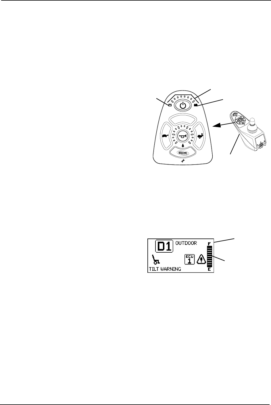
SECTION 9—BATTERIES
Pronto® M91™Base with SureStep® 62 Part No 1143153
When to Charge Batteries
SPJ+ Joysticks
NOTE:Forthisprocedure,refertoFIGURE 9.4.
TheInformationGaugeDisplaylocatedonthefrontofthejoystickhousing,itprovides
thestate‐of‐batterycharge,includingnotificationofwhenthebatteryrequirescharging.
Italsoprovidesthefollowinginformationtotheuseronthestatusofthewheelchair:
A. GREENLEDsarelit,indicatingwell
chargedbatteries.
B. AMBERLEDsarelit,indicating
batteriesaremoderatelycharged.
Rechargebatteriesbeforetakinga
longtrip.
C. REDLEDsarelit,indicating
batteriesarerunningoutofcharge.
Rechargebatteriesassoonas
possible.
FIGURE 9.4 SPJ+ Joysticks
MPJ+ Joystick
NOTE:Forthisprocedure,refertoFIGURE 9.5.
ThefarrightsideofthedisplayscreenistheBatteryGaugeDisplay(BGD).Itprovides
informationontheremainingchargeinthebatteries.
Atfullcharge,solidblocksfillinallten
segmentsbetweenE(Empty)andF(Full).
Asthebatterybecomesdischarged,the
segmentswillprogressivelydisappeara
baratatimeuntilnosegmentsappear
betweenEandF.Atthisleveltheuser
shouldchargethebatteriesassoonas
possible.
FIGURE 9.5 MPJ+ Joystick
Battery Charger/
Programming Port
Batteries Full
Batteries
Empty
Information Gauge Display
Battery Gage
Display
Display
Screen

SECTION 9—BATTERIES
Part No 1143153 63 Pronto® M91™Base with SureStep®
Charging Batteries
DANGER
When using an extension cord, use only a three wire extension cord having at least
16 AWG (American Wire Gauge) wire and the same or higher electrical rating as
the devise being connected. Use of improper extension cord could result in a risk of
fire and electric shock. Three prong to two prong adapters should not be used. Use
of three prong adapters can result in improper grounding and present a shock
hazard to the user.
WARNING
Never attempt to recharge the batteries by attaching cables directly to the battery
terminals.
DO NOT attempt to recharge the batteries and operate the wheelchair at the same
time.
DO NOT attempt to recharge the batteries when the wheelchair has been exposed
to ANY type of moisture.
DO NOT attempt to recharge the batteries when the wheelchair is outside.
DO NOT sit in the wheelchair while charging the batteries.
DO NOT attempt to recharge the batteries using both the on-board battery
charger AND an independent battery charger (plugged into the joystick charger
port) at the SAME time. Doing so will reduce the life of the batteries.
READ and CAREFULLY follow the manufactures instructions for each charger
(supplied or purchased). If charging instructions are not supplied, consult a qualified
technician for proper procedures prior to use.
CAUTION
New batteries MUST be fully charged prior to initial use of the wheelchair.
Always fully charge new batteries before initial use or battery life will be reduced.
As a general rule, you should recharge your batteries as frequently as possible to
assure the longest possible life and to minimize required charging time. Plan to
recharge them when you do not anticipate using the wheelchair.
Somebasicconceptswhichwillhelpyouunderstandthisautomaticprocessare:
Theamountofelectricalcurrentdrawnwithinagiventimetochargeabatteryiscalled
“chargerate”.If,duetousage,thechargestoredinthebatteryislow,thechargerateis
high.Asachargebuildsup,thechargerateisreduced,andthebatterychargerrate
decreasestoa“tricklecharge”.
NOTE:Ifthebatteriesneedtobechargedmoreoftenortakelongertochargethannormal,they
mayneedtobereplaced.Contactaqualifiedtechnician.
NOTE:Thebatteriescanbechargedusingtheon‐boardbatterychargerorbypluggingan
independentbatterychargerintotheportlocatedonthefrontoftheSPJ‐80/DPJ/MPJjoysticks.

SECTION 9—BATTERIES
Pronto® M91™Base with SureStep® 64 Part No 1143153
Battery Charger Operation
WARNING
READ and CAREFULLY follow the manufacturer’s instructions for each charger
(supplied or purchased). If charging instructions are not supplied, consult a qualified
technician for proper procedures prior to use.
If the circuit breaker trips repeatedly, IMMEDIATELY unplug charger and contact
dealer or a qualified technician.
Three prong to two prong adapters should not be used. Using three prong adapters
can result in improper grounding and present a shock hazard to user.
On-Board Battery Charger
WARNING
Use of improper extension cord could result in risk of fire and electric shock.
When using an extension cord, use only a three wire extension cord having at least
16 AWG (American Wire Gauge) wire and the same or higher electrical rating as
the device being connected.
Ensure the pins of the extension cord plug are the same number, size, and shape as
those on the charger.
DO NOT under any circumstances cut or remove the round grounding plug from
the charger AC cable plug or the extension cord plug.
NOTE:Forthisprocedure,refertoFIGURE 9.6onpage65.
NOTE:Chargeindicatorlightisonlyvisiblewithrearshroudremoved.
1. PlugthefemaleconnectoroftheACpowercord(supplied)totheACreceptacleon
thechargerandpluginthemaleconnectorontheACpowercordintothewalloutlet.
2. TheOn/OffLEDindicatorilluminatessolidREDindicatingthatthechargerisOn.
3. IftheOn/OffLEDindicatoris“Blinking”RED,thisisabnormal.UnplugACpower
cordfromtheon‐boardbatterychargerandwalloutlet.ContactInvacareatthe
numberlistedonthebackpageofthismanual.
4. WhentheOn/OffLEDindicatorlightisOff,chargerisOff.
5. WhentheChargeLEDindicatorlightisYELLOW,thebatteriesarecharging.
6. WhentheChargeLEDindicatorlightissolidGREEN,thebatteriesarefullycharged
(astheirconditionwillallow).Atthispoint,thechargerautomaticallystopscharging.
7. Whenchargingiscomplete,unplugthemaleconnectoroftheACpowercordfromthe
walloutletandthenunplugthefemaleconnectoroftheACpowercordfromtheAC
receptacleonthecharger.

SECTION 9—BATTERIES
Part No 1143153 65 Pronto® M91™Base with SureStep®
WARNING
DO NOT operate wheelchair with AC power cord attached to the wheelchair.
FIGURE 9.6 On-Board Battery Charger
Independent Charger
WARNING
READ and CAREFULLY follow the individual instructions for each charger (supplied
or purchased). If charging instructions are not supplied, consult a qualified
technician for proper procedures.
CAUTION
DO NOT use an independent charger with an output rating of over 8A (amps).
Otherwise, damage may occur.
NOTE:Forthisprocedure,refertoFIGURE 9.7onpage66.
NOTE:ThechargerportlocatedontheFrontofthejoystickrequirestheuseofanindependent
charger.TheindependentchargerisNOTsuppliedwiththewheelchair.
To Wall Outlet
Male Connector on AC Power Cord
(Connects to Wall Outlet)
AC Receptacle
on Charger
Charger
(Hidden from View)
NOTE:Wheelchairshownwithoutseat
forclarity.
NOTE:Chargeindicatorlightisonly
visiblewhenrearshroudisremoved.
Female Connector on AC
Power Cord
(Connects to AC
Receptacle on Charger)
CHARGING INDICATOR STATUS
YELLOW Charging (Under 80%)
“Blinking” YELLOW Partially Charges (Over 80%)
Solid GREEN Fully Charges
LED “Off” Charger Disconnected
Solid RED or
“Blinking” RED
Under Voltage
Over Voltage
Over Temperature
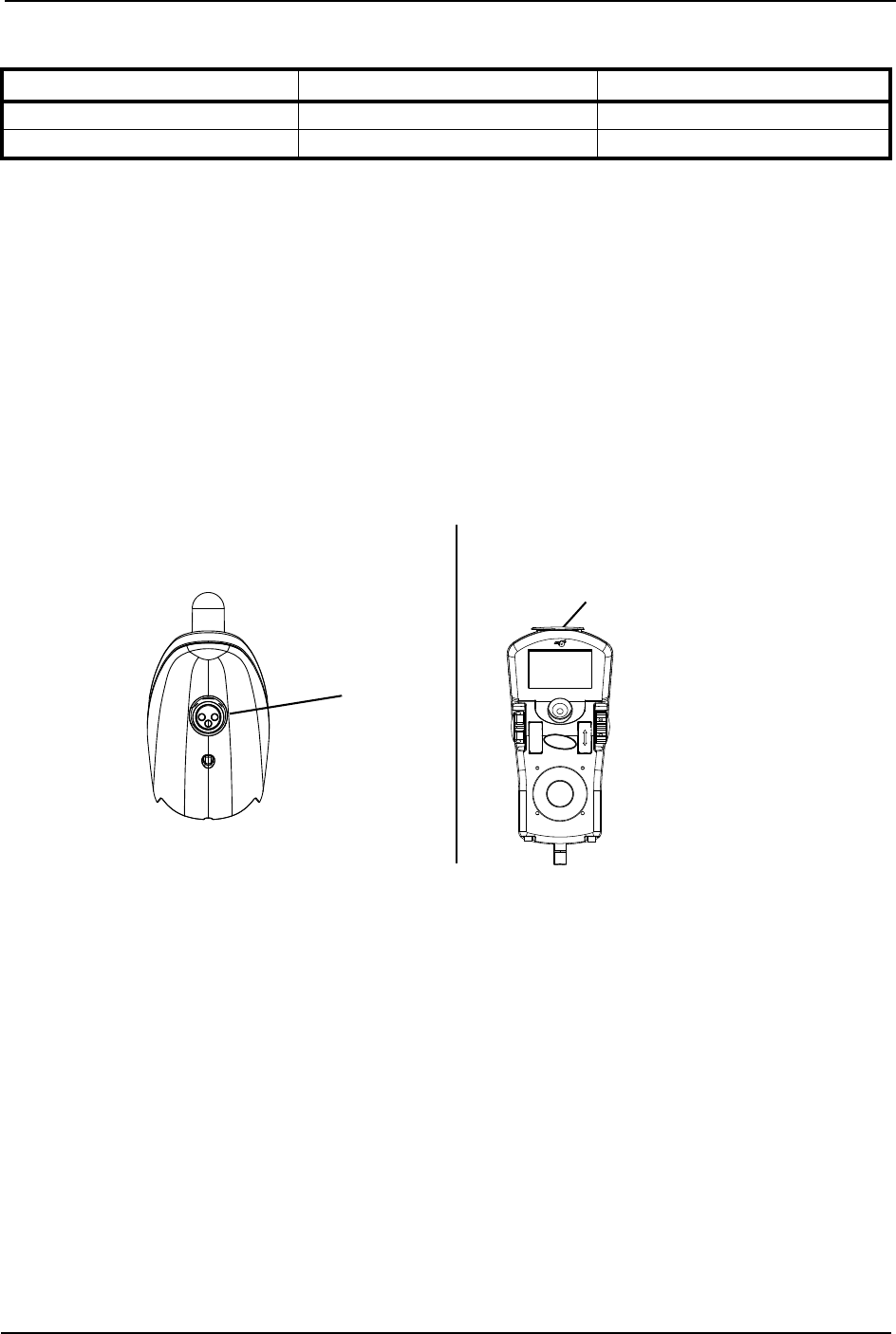
SECTION 9—BATTERIES
Pronto® M91™Base with SureStep® 66 Part No 1143153
RequiredItems:
1. Attachthebatterychargerconnectortothechargerportonthejoystick.
2. Plugthecharger’sACpowercord,orextension,intothegrounded120VACwall
outlet.
3. Waituntilchargingiscomplete.
NOTE:Alloweighthoursfornormalcharging.Largerbatteries(greaterthan55ampere‐hours)or
severelydischargedbatteriesmayrequireuptosixteenhourstobeproperlychargedandequalized.
NOTE:Itisadvantageoustorechargefrequentlyratherthanonlywhennecessary.Infact,a
battery’slifeisextendedifthechargelevelismaintainedwellabovealowcondition.
NOTE:Ifthebatteriesneedtobechargedmoreoftenortakelongertochargethannormal,they
mayneedtobereplaced.ContactanInvacaredealerforservice.
FIGURE 9.7 Charging Batteries
TOOL QUANTITY COMMENTS
Battery Charger 1 Supplied
Extension Cord 1 Not Supplied
MPJ JoystickSPJ Joysticks
Charger/
Programming
Port
Charger/Programming Port (On
Front of Joystick)

SECTION 10—TRANSPORT READY PACKAGE
Part No 1143153 67 Pronto® M91™Base with SureStep®
SECTION 10—TRANSPORT READY
PACKAGE
NOTE:Theinformationinthissectionisforwheelchairsorderedwiththetransportreadypackage
ONLY.
WARNING
Contact Invacare Corporation (800-333-6900) with any questions about using this
wheelchair for seating in a motor vehicle.
When feasible, wheelchair occupants should transfer into the vehicle seat and use
the OEM (Original Equipment Manufacturer) vehicle-installed restraint system.
This wheelchair has been dynamically tested in a forward-facing mode with the
specified crash test dummy restrained by BOTH pelvic and shoulder belt(s), and
that BOTH pelvic and upper torso belt(s) should be used to reduce the possibility of
head and chest impacts with vehicle components.
Use ONLY Wheelchair Tie-down and Occupant Restraint Systems (WTORS) which
meet the requirements of the SAE (Society of Automotive Engineers) J2249
Recommended Practice during travel in a motor vehicle.
This wheelchair has been tested for seating in a motor vehicle with the factory
installed seating system ONLY.
This wheelchair MUST be in a forward facing position during travel in a motor
vehicle.
This wheelchair is equipped and has been dynamically tested to rely on
WHEELCHAIR-ANCHORED pelvic belts. If desired, VEHICLE-ANCHORED pelvic
belts may be used.
IT IS STRONGLY RECOMMENDED THAT BOTH PELVIC AND UPPER-TORSO
BELT(S) BE USED TO REDUCE THE RISK OF INJURY.
To reduce the potential of injury to vehicle occupants, wheelchair-mounted
accessories, including but not limited to IV poles, trays, respiratory equipment,
backpacks, and other personal items should be removed and secured separately.
Postural supports, positioning devices, and/or strap(s) should not be relied on for
occupant restraint. These items may be used IN ADDITION TO the wheelchair-
anchored or vehicle-anchored belts.
Wheelchairs with adjustable seat angles MUST be set to 10°.
DO NOT alter or substitute wheelchair frame parts, components, or seating
systems.
A sudden stop and/or collision may structurally damage your wheelchair.
Wheelchairs involved in such incidents should be replaced.
Spill proof batteries, such as “gel cells”, should be installed on wheelchairs to be
used during travel in a motor vehicle.
TRANSPORT READY PACKAGES ARE NOT RETROFITTABLE TO EXISTING
MODELS AND ARE NOT FIELD SERVICEABLE.

SECTION 10—TRANSPORT READY PACKAGE
Pronto® M91™Base with SureStep® 68 Part No 1143153
About Transport Ready Packages
TRROincludesfourfactory‐installedtransportbracketsandawheelchairanchored
pelvicbelt.TRROhasbeencrash‐testedinaccordancewithANSI/RESNAWCVol1
Section19FrontalImpactTestrequirementsforwheelchairswitha168lbcrashdummy,
whichcorrespondstoapersonwithaweightof114to209lbs.
TRBKTSincludesfourfactory‐installedwheelchairtransportbrackets.TRBKTShasnot
beencrash‐testedinaccordancewithWC19.Invacarerecommendsthatthesetransport
bracketsbeusedonlytosecureanunoccupiedwheelchairduringtransport.
Asofthisdate,theDepartmentofTransportationhasnotapprovedanytie‐downsystems
fortransportationofauserwhileinawheelchair,inamovingvehicleofanytype.Itis
Invacare’spositionthatusersofwheelchairsshouldbetransferredintoappropriate
seatinginvehiclesfortransportationandusebemadeoftherestraintsmadeavailableby
theautoindustry.Invacarecannotanddoesnotrecommendanywheelchair
transportationsystems.
Compliance Information
ThiswheelchairconformswiththerequirementsoftheANSI/RESNAWC/Vol.1‐Section
19.
NOTE:ANSI=AmericanNationalStandardsInstitute,RESNA=RehabilitationEngineering
andAssistiveTechnologySocietyofNorthAmerica.
Thiswheelchairhasbeendynamicallytestedinaforward‐facingmodewiththespecified
crashtestdummy,whichcorrespondstoapersonwithaweightof114‐209pounds,
restrainedbyBothpelvicandshoulderbeltsinaccordancewithansi/resnawcVol1
Section19.Bothpelvicanduppertorsobeltsshouldbeusedtoreducethepossibilityof
headandchestimpactswithvehiclecomponents.
Specifications
MODEL WHEELCHAIR WEIGHT LIMIT
M91 Standard Up to 300 lbs
M91 Heavy Duty Up to 400 lbs
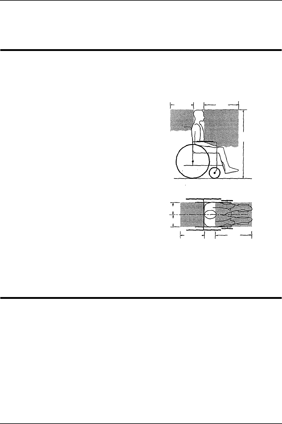
SECTION 10—TRANSPORT READY PACKAGE
Part No 1143153 69 Pronto® M91™Base with SureStep®
Securing the Wheelchair to the Vehicle
Positioning the Wheelchair in the Vehicle
WARNING
This wheelchair must be in a forward
facing position during travel in a motor
vehicle.
The recommended clear zones for
wheelchair seated occupants restrained
by BOTH pelvic and upper torso belt(s)
and ONLY by a pelvic belt are shown in
the diagrams and described below.
Frontal Clear Zones (FCZ) need to be
LARGER when upper torso belt(s) are
NOT used.
The rear clear zone of 16-inches is
measured from the rearmost point on
an occupant’s head.
The frontal clear zone is measured from
the frontmost point on an occupant’s
head and is 26-inches with pelvic and
upper-torso belt(s) and 37-inches with
ONLY a pelvic belt.
The frontal clear zone may not be
achievable for wheelchair-seated
drivers.
The estimated seated height (HHT) from the ground or floor to the top of the
wheelchair-seated occupant’s head ranges from approximately 47-inches for a small
adult female to about 61-inches for a tall adult male.
16 in.
Frontal Clear
Zone
Side View
Top View
HHT
FCZ
Frontal Clear
Zone
16 in.
8 in.
8 in.
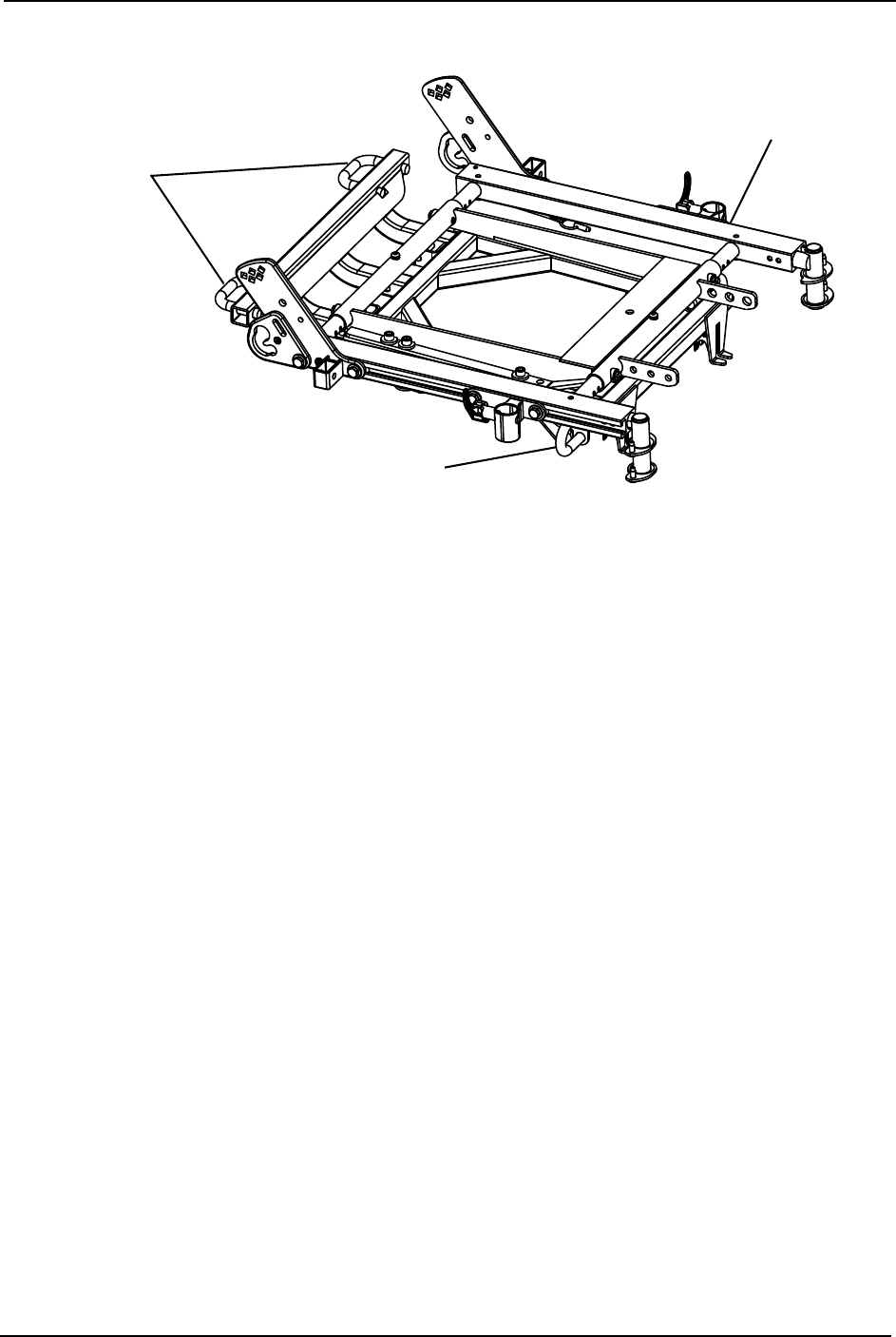
SECTION 10—TRANSPORT READY PACKAGE
Pronto® M91™Base with SureStep® 70 Part No 1143153
Securement Points
FIGURE 10.1 Securement Points
Securing the Wheelchair
ThiswheelchairistobeusedonlywithWheelchairTie‐downandOccupantRestraint
Systems(WTORS)thathavebeeninstalledinaccordancewiththemanufacturerʹs
instructionsandSAEJ2249.
NOTE:AcopyofSAEJ2249WheelchairTie‐downandOccupantRestraintSystems(WTORS)
foruseinMotorVehiclescanbeobtainedfrom:SAEInternational,400CommonwealthDrive,
Warrendale,PA 15096‐0001,(877)606‐7232or(724)776‐4970.
AttachWTORStothetie‐downbracketsinaccordancewiththemanufacturerʹs
instructionsandSAEJ2249.
Tie-Down Bracket
(hidden from view)
Tie-Down
Brackets
Tie-Down Bracket

SECTION 10—TRANSPORT READY PACKAGE
Part No 1143153 71 Pronto® M91™Base with SureStep®
Securing the Occupant
Wheelchair-Anchored Belts
WARNING
The pelvic belt that is provided by Invacare has been tested for use in a motor vehi-
cle on this wheelchair ONLY. DO NOT replace the pelvic belt with a different style
pelvic belt.
NOTE:Forthisprocedure,refertoFIGURE 10.2.
Thewheelchairhasbeenprovidedwithapelvicbeltwhichmeetstherequirementsof
ANSI/RESNAW/C19.
Thepelvicbelt,providedbyInvacare,hasbeendesignedtoaccommodateuseoneither
sideofthevehicle.Ifnecessary,followtheinstructionsbelowtoreversetheorientationof
thepelvicbelttoaccommodatethevehicle‐anchoreduppertorsobelt.
1. Installthepelvicbeltpin(DETAILʺAʺofFIGURE2)intothelargeendoftheslotin
thebeltmountingbracket.Rotatedownwardandforwarduntilitsnapsintoplaceinto
thesmallendoftheslot.
NOTE:Notethepositionofthemaleendofthebeltwheninstallingthepelvicbeltontothebelt
mountingbrackets.Themaleendofthepelvicbelt(DETAILʺAʺofFIGURE2)hasapinwhich
isusedtosecurethevehicle‐anchoreduppertorsobelt.
2. RepeatSTEP1fortheoppositebeltmountingbracket.
3. Installthevehicle‐anchoreduppertorsobeltontothepinonthemaleendofthepelvic
belt.
FIGURE 10.2 Wheelchair-Anchored Belts
Pin
Pin
Pin
(Used to secure the vehicle
anchored upper torso belt)
Male End
DETAIL “A” Back Angle
Bracket
Large End
of Slot
Belt Mounting
Bracket
Small End of Slot
Pelvic Belt

SECTION 10—TRANSPORT READY PACKAGE
Pronto® M91™Base with SureStep® 72 Part No 1143153
Vehicle-Anchored Belts
NOTE:Forthisprocedure,refertoFIGURE 10.3.
Thiswheelchairhasanoverallratingof“A ” withregardtoaccommodatingtheuseand
fitofvehicle‐anchoredbelts.Thisratingisscoredasfollows:
ThetestforLateralStabilityDisplacementforPoint(P)isshowninFIGURE 10.3.The
averagetestresultforpoint(P)is0.44‐inches(11.2mm).
FIGURE 10.3 Vehicle-Anchored Belts
Seating System
WARNING
This wheelchair has been tested for seating in a motor vehicle with the factory
installed seating system ONLY.
Ensurethatthefactoryinstalledseatingsystemissecuredtothewheelchairframebefore
operation.Refertotheseatingsystemowner’smanual.
RATING DESCRIPTION
AExcellent
BGood
CFair
DPoor
Point (P)
Test Platform
45°
NOTE:Rearviewofthe
wheelchairandhuman
surrogatesecuredontest
platformandtiltedto45°.

SECTION 10—TRANSPORT READY PACKAGE
Part No 1143153 73 Pronto® M91™Base with SureStep®
Positioning Belts
WARNING
The angle of the pelvic belt should be
within the preferred zone of 45 to 75
degrees to the horizontal OR within the
optional zone of 30 to 45 degrees to the
horizontal.
Steeper side-view pelvic belt angles are
especially important if the pelvic belt is
intended to be used for postural support
in addition to occupant restraint in a
frontal crash. Steeper angles will reduce
the tendency for a vertical gap to
develop between the user and the belt
due to compliance of seat cushions and
belt movement, thereby reducing the
tendency for the user to slip under the
belt and for the belt to ride up on the
soft abdomen during normal use.
Steeper belt angles also reduce the tendency for upper-torso belts to pull the pelvic
belt onto the abdomen during frontal impact loading.
NOTE:Forthisprocedure,refertoFIGURE 10.4.
1. Thepelvicbeltshouldbewornlowacrossthefrontofthepelvis.
2. Positiontheuppertorsobelt(s)overtheshoulders.
3. Thebelt(s)shouldnotbeheldawayfromthebodybywheelchaircomponentsor
parts,includingbutnotlimitedtowheelchairarmrestsorwheels.Referto
FIGURE 10.4forproperandimproperpositioningofthebelts.
4. Ensurethebelt(s)arenottwisted.
5. Adjustbeltsasfirmlyaspossible,beingmindfulofusercomfort.
FIGURE 10.4 Positioning Belts
Preferred Zone
Optional Zone
Side View
30°
45°
70°
DO POSITION BELT INSIDE OF
ARMRESTS, WHEELS, ETC.
DO NOT POSITION BELT OUTSIDE OF
ARMRESTS, WHEELS, ETC.


GLOBAL LIMITED WARRANTY (EXCLUDING CANADA)
Part No 1143153 75 Pronto® M91™Base with SureStep®
GLOBAL LIMITED WARRANTY
(EXCLUDING CANADA)
PLEASE NOTE: THE WARRANTY BELOW HAS BEEN DRAFTED TO COMPLY WITH FEDERAL LAW
APPLICABLE TO PRODUCTS MANUFACTURED AFTER JULY 4, 1975.
This warranty is extended only to the original purchaser who purchases this product within any country
excluding CANADA when new and unused from Invacare or a dealer. This warranty is not extended to any
other person or entity and is not transferable or assignable to any subsequent purchaser or owner.
Coverage under this warranty will end upon any such subsequent sale or other transfer of title to any other
person. For product purchased in Canada, please refer to the Canada Limited Warranty.
This warranty gives you specific legal rights and you may also have other legal rights which vary from state to
state.
Invacare warrants the base frame to be free from defects in materials and workmanship for a period of five (5)
years from the date of purchase from Invacare or a dealer, with a copy of the seller’s invoice required for coverage
under this warranty. Invacare warrants all electronics and electrical components (excluding batteries), motors and
gearboxes to be free from defects in materials and workmanship for a period of one (1) year from the date of
purchase from Invacare or a dealer, with a copy of the seller’s invoice required for coverage under this warranty.
Invacare warrants all batteries to be free from defects in materials and workmanship for a period of six (6) months
from the date of purchase from Invacare or a dealer, with a copy of the seller’s invoice required for coverage under
this warranty. Invacare warrants all remaining components (excluding all upholstered materials, padded materials,
tires and wheels) to be free from defects in materials and workmanship for a period of one (1) year from the date
of purchase from Invacare or a dealer, with a copy of the seller’s invoice required for coverage under this warranty.
If within such warranty periods any such product component shall be proven to be defective, the product
component shall be repaired or replaced, at Invacare's option. This warranty does not include any labor or
shipping charges incurred in replacement part installation or repair of any such product. Invacare's sole obligation
and your exclusive remedy under this warranty shall be limited to such repair and/or replacement.
For warranty service, please contact the dealer from whom you purchased your Invacare product. In the event you
do not receive satisfactory warranty service, please write directly to Invacare at the address on the bottom of the
back cover. Provide dealer's name address, date of purchase, indicate nature of the defect and, if the product is
serialized, indicate the serial number. Do not return products to our factory without our prior consent.
LIMITATIONS AND EXCLUSIONS: THE FOREGOING WARRANTY SHALL NOT APPLY TO SERIAL
NUMBERED PRODUCTS IF THE SERIAL NUMBER HAS BEEN REMOVED OR DEFACED, PRODUCTS
SUBJECT TO NEGLIGENCE, ACCIDENT, IMPROPER OPERATION, MAINTENANCE OR STORAGE,
COMMERCIAL OR INSTITUTIONAL USE, PRODUCTS MODIFIED WITHOUT INVACARE'S EXPRESS
WRITTEN CONSENT (INCLUDING, BUT NOT LIMITED TO, MODIFICATION THROUGH THE USE OF
UNAUTHORIZED PARTS OR ATTACHMENTS); PRODUCTS DAMAGED BY REASON OF REPAIRS MADE
TO ANY COMPONENT WITHOUT THE SPECIFIC CONSENT OF INVACARE, OR TO A PRODUCT
DAMAGED BY CIRCUMSTANCES BEYOND INVACARE'S CONTROL, AND SUCH EVALUATION WILL BE
SOLELY DETERMINED BY INVACARE. THE WARRANTY SHALL NOT APPLY TO PROBLEMS ARISING
FROM NORMAL WEAR AND TEAR OR FAILURE TO ADHERE TO THE PRODUCT INSTRUCTIONS. A
CHANGE IN OPERATING NOISE, PARTICULARLY RELATIVE TO MOTORS AND GEARBOXES DOES NOT
CONSTITUTE A FAILURE OR DEFECT AND WILL NOT BE REPAIRED; ALL DEVICES WILL EXHIBIT
CHANGES IN OPERATING NOISE DUE TO AGING.
THE FOREGOING EXPRESS WARRANTY IS EXCLUSIVE AND IN LIEU OF ANY OTHER WARRANTIES
WHATSOEVER, WHETHER EXPRESS OR IMPLIED, INCLUDING THE IMPLIED WARRANTIES OF
MERCHANTABILITY AND FITNESS FOR A PARTICULAR PURPOSE, AND THE SOLE REMEDY FOR
VIOLATIONS OF ANY WARRANTY WHATSOEVER, SHALL BE LIMITED TO REPAIR OR REPLACEMENT
OF THE DEFECTIVE PRODUCT PURSUANT TO THE TERMS CONTAINED HEREIN. THE APPLICATION
OF ANY IMPLIED WARRANTY WHATSOEVER SHALL NOT EXTEND BEYOND THE DURATION OF THE
EXPRESS WARRANTY PROVIDED HEREIN AND INVACARE SHALL NOT BE LIABLE FOR ANY
CONSEQUENTIAL OR INCIDENTAL DAMAGES WHATSOEVER; SOME STATES DO NOT ALLOW THE
EXCLUSION OR LIMITATION OF INCIDENTAL OR CONSEQUENTIAL DAMAGE, OR LIMITATION OF
HOW LONG AN IMPLIED WARRANTY LASTS, SO THE ABOVE EXCLUSION AND LIMITATION MAY NOT
BE APPLICABLE.
THIS WARRANTY SHALL BE EXTENDED TO COMPLY WITH STATE/PROVINCIAL LAWS AND
REQUIREMENTS.

CANADA LIMITED WARRANTY
PLEASE NOTE: THE WARRANTY BELOW HAS BEEN DRAFTED TO COMPLY WITH FEDERAL LAW
APPLICABLE TO PRODUCTS MANUFACTURED AFTER JULY 4, 1975.
This warranty is extended only to the original purchaser who purchases this product within Canada when
new and unused from Invacare or a dealer. This warranty is not extended to any other person or entity and
is not transferable or assignable to any subsequent purchaser or owner. Coverage under this warranty will
end upon any such subsequent sale or other transfer of title to any other person.
This warranty gives you specific legal rights and you may also have other legal rights which vary from state to
state.
Invacare warrants the base frame to be free from defects in materials and workmanship for a period of five (5)
years from the date of purchase from Invacare or a dealer, with a copy of the seller’s invoice required for coverage
under this warranty. Invacare warrants all electronics and electrical components (excluding batteries), motors and
gearboxes to be free from defects in materials and workmanship for a period of two (2) years from the date of
purchase from Invacare or a dealer, with a copy of the seller’s invoice required for coverage under this warranty.
Invacare warrants all batteries to be free from defects in materials and workmanship for a period of six (6) months
from the date of purchase from Invacare or a dealer, with a copy of the seller’s invoice required for coverage under
this warranty. Invacare warrants all remaining components (excluding all upholstered materials, padded materials,
tires and wheels) to be free from defects in materials and workmanship for a period of one (1) year from the date
of purchase from Invacare or a dealer, with a copy of the seller’s invoice required for coverage under this warranty.
If within such warranty periods any such product component shall be proven to be defective, the product
component shall be repaired or replaced, at Invacare's option. This warranty does not include any labor or
shipping charges incurred in replacement part installation or repair of any such product. Invacare's sole obligation
and your exclusive remedy under this warranty shall be limited to such repair and/or replacement.
For warranty service, please contact the dealer from whom you purchased your Invacare product. In the
event you do not receive satisfactory warranty service, please write directly to Invacare at the address on
the bottom of the back cover. Provide dealer's name address, date of purchase, indicate nature of the defect
and, if the product is serialized, indicate the serial number. Do not return products to our factory without
our prior consent.
LIMITATIONS AND EXCLUSIONS: THE FOREGOING WARRANTY SHALL NOT APPLY TO SERIAL
NUMBERED PRODUCTS IF THE SERIAL NUMBER HAS BEEN REMOVED OR DEFACED, PRODUCTS
SUBJECT TO NEGLIGENCE, ACCIDENT, IMPROPER OPERATION, MAINTENANCE OR STORAGE,
COMMERCIAL OR INSTITUTIONAL USE, PRODUCTS MODIFIED WITHOUT INVACARE'S EXPRESS
WRITTEN CONSENT (INCLUDING, BUT NOT LIMITED TO, MODIFICATION THROUGH THE USE
OF UNAUTHORIZED PARTS OR ATTACHMENTS); PRODUCTS DAMAGED BY REASON OF REPAIRS
MADE TO ANY COMPONENT WITHOUT THE SPECIFIC CONSENT OF INVACARE, OR TO A
PRODUCT DAMAGED BY CIRCUMSTANCES BEYOND INVACARE'S CONTROL, AND SUCH
EVALUATION WILL BE SOLELY DETERMINED BY INVACARE. THE WARRANTY SHALL NOT APPLY
TO PROBLEMS ARISING FROM NORMAL WEAR AND TEAR OR FAILURE TO ADHERE TO THE
PRODUCT INSTRUCTIONS. A CHANGE IN OPERATING NOISE, PARTICULARLY RELATIVE TO
MOTORS AND GEARBOXES DOES NOT CONSTITUTE A FAILURE OR DEFECT AND WILL NOT BE
REPAIRED; ALL DEVICES WILL EXHIBIT CHANGES IN OPERATING NOISE DUE TO AGING.
THE FOREGOING EXPRESS WARRANTY IS EXCLUSIVE AND IN LIEU OF ANY OTHER
WARRANTIES WHATSOEVER, WHETHER EXPRESS OR IMPLIED, INCLUDING THE IMPLIED
WARRANTIES OF MERCHANTABILITY AND FITNESS FOR A PARTICULAR PURPOSE, AND THE
SOLE REMEDY FOR VIOLATIONS OF ANY WARRANTY WHATSOEVER, SHALL BE LIMITED TO
REPAIR OR REPLACEMENT OF THE DEFECTIVE PRODUCT PURSUANT TO THE TERMS
CONTAINED HEREIN. THE APPLICATION OF ANY IMPLIED WARRANTY WHATSOEVER SHALL
NOT EXTEND BEYOND THE DURATION OF THE EXPRESS WARRANTY PROVIDED HEREIN AND
INVACARE SHALL NOT BE LIABLE FOR ANY CONSEQUENTIAL OR INCIDENTAL DAMAGES
WHATSOEVER; SOME STATES DO NOT ALLOW THE EXCLUSION OR LIMITATION OF
INCIDENTAL OR CONSEQUENTIAL DAMAGE, OR LIMITATION OF HOW LONG AN IMPLIED
WARRANTY LASTS, SO THE ABOVE EXCLUSION AND LIMITATION MAY NOT BE APPLICABLE.
THIS WARRANTY SHALL BE EXTENDED TO COMPLY WITH STATE/PROVINCIAL LAWS AND
REQUIREMENTS.
Invacare Corporation www.invacare.com
USA
One Invacare Way
Elyria, Ohio USA
44036-2125
800-333-6900
Canada
570 Matheson Blvd E Unit 8
Mississauga Ontario
L4Z 4G4 Canada
800-668-5324
All rights reserved. Trademarks are identified
by the symbols ™ and ®. All trademarks are
owned by or licensed to Invacare
Corporation unless otherwise noted.
©2008 Invacare Corporation
Part No 1143153 Rev D - 10/08
