Invenco Group G6OPT Payment terminal with RF Card Reader User Manual DCV 00001 Rev 05 S2 G6 OPT Installation Guide
Invenco Group Ltd Payment terminal with RF Card Reader DCV 00001 Rev 05 S2 G6 OPT Installation Guide
User Manual

08
Fall
G6 OPT
Installation Guide
Revision 5
July 2014

DCV-00001 Rev 05 S2 G6 OPT Installation Guide Page 2
Table of Contents
1 Introduction ............................................................................................. 4
2 Safety & Compliance Information ............................................................ 5
2.1 Preliminary Precautions .............................................................. 5
2.2 Emergency Total Electrical Shut-Off ........................................... 5
2.3 Total Electrical Shut-Off Before Access ...................................... 5
2.4 Evacuation, Barricading and Shut-Off ......................................... 5
2.5 Read the Manual ......................................................................... 5
2.6 Follow the Regulations ................................................................ 5
2.7 Replacement Parts ...................................................................... 5
2.8 Safety Symbols and Warning Words ........................................... 6
2.9 Prevent Explosions and Fires ..................................................... 6
2.10 No Open Flames ......................................................................... 6
2.11 No Sparks - No Smoking ............................................................. 6
2.12 Working Alone ............................................................................. 6
2.13 Working With Electricity Safely.................................................... 6
2.14 Hazardous Materials ................................................................... 7
2.15 Informing Emergency Personnel ................................................. 7
2.16 Computer Programs and Documentation .................................... 7
2.17 Approvals .................................................................................... 7
2.18 European Directives .................................................................... 7
2.19 Important Radio, FCC and Interference Information ................... 8
2.20 RF Exposure information ............................................................ 8
2.21 Laser Warning ............................................................................. 8
3 Product Features .................................................................................... 9
3.1 Location of Features ................................................................... 9
3.2 Accessories in the box .............................................................. 10
3.3 Location of Mounting Points ...................................................... 10
4 Installation ............................................................................................. 11
4.1 Considerations for New Enclosures .......................................... 11
4.2 Tools Required .......................................................................... 13
4.3 In A New Pump or Cabinet ........................................................ 13

DCV-00001 Rev 05 S2 G6 OPT Installation Guide Page 3
4.4 Replacement of a G5 Product ................................................... 14
4.4.1 Power Supply Considerations ...................................................... 14
4.4.2 Selection of Retrofit Options ........................................................ 15
4.4.3 Physical Retrofit ........................................................................... 15
4.4.4 Retrofit Kit Parts ........................................................................... 16
4.5 Wiring ........................................................................................ 17
4.5.1 Protective Earth ........................................................................... 17
4.5.2 Ethernet LAN ............................................................................... 17
4.5.3 DC Power Supply......................................................................... 17
4.5.4 Main Power Supply Wiring ........................................................... 18
4.5.5 Wiring Completion........................................................................ 18
5 First Power-Up ...................................................................................... 19
6 Basic Maintenance ................................................................................ 20
6.1 Cleaning .................................................................................... 20
6.2 Paper-Roll Replacement (only for models with printer) ............. 20
6.3 Clearing a Paper Jam (only for models with printer) ................. 22
7 Removal & Reinstallation ...................................................................... 24
8 Drawings ............................................................................................... 26
8.1 Dimensions ............................................................................... 26
8.2 Mounting – New Installation ...................................................... 28
8.3 Retrofit for G5 OPT with Motorised Card Reader ...................... 30
8.4 Retrofit for G5 OPT with Manual Card Reader .......................... 31
9 Typical Wiring ....................................................................................... 32
10 Notes..................................................................................................... 33

DCV-00001 Rev 05 S2 G6 OPT Installation Guide Page 4
1 Introduction
Congratulations on your purchase of a Generation 6 Outdoor Payment Terminal (G6 OPT).
This product is the result of years of development and experience crafting terminal products
for the retail petroleum industry and represents the state of the art in equipment for your
customers.
When properly installed and maintained your terminal will provide many years of service.
There are few moving parts and minimal connections, and all parts have been designed to
give a good service life.
Please read this guide thoroughly before starting installation.
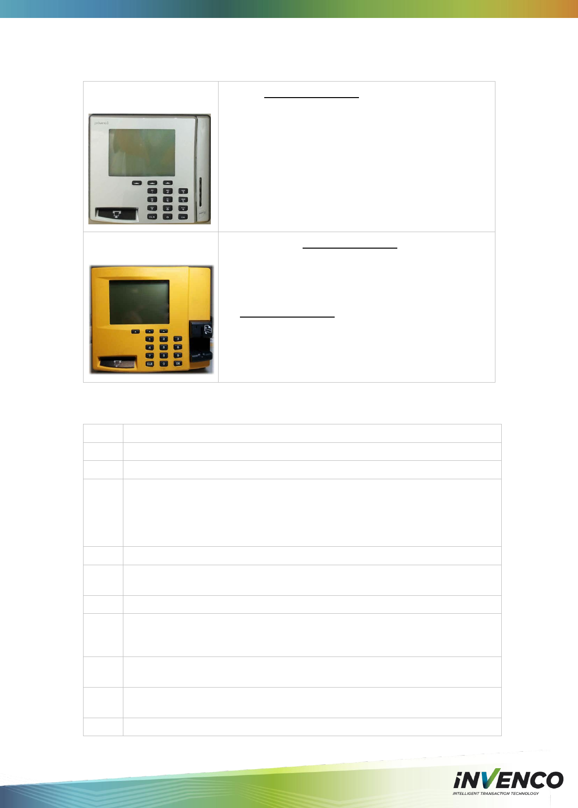
This guide is intended for the following variants of the G6 OPT:
Model →
6500x
6505x
6520x
6525x
Features↓
Contactless
2D Barcode
The G6 OPT is intended for use on fuel station forecourts, but is also suitable for mounting
into any appropriate, physically secure cabinet.
This guide deals primarily with the requirements for mounting into a fuel pump-head, however
the steps are applicable to any cabinet. Specific steps and precautions for pump head
installation are highlighted.

DCV-00001 Rev 05 S2 G6 OPT Installation Guide Page 5
2 Safety & Compliance Information
This section introduces the hazards and safety precautions associated with installing,
inspecting, maintaining or servicing this product. Before performing any task on this product,
read this safety information and the applicable sections in this manual, where additional
hazards and safety precautions for your task will be found. Fire, explosion or electrical shock
could occur and cause death or serious injury if these safe service procedures are not
followed.
2.1 Preliminary Precautions
You are working in a potentially dangerous environment of flammable fuels, vapours, and
high voltage. Only trained or authorized individuals knowledgeable in the related procedures
should install, inspect, maintain or service this equipment.
2.2 Emergency Total Electrical Shut-Off
The first and most important information you must know is how to stop all fuel flow to the
pump and island. Locate the switch or circuit breakers that shut-off all power to all fuelling
equipment and dispensing devices.
2.3 Total Electrical Shut-Off Before Access
Any procedure requiring access to electrical components or the electronics of a
pump/dispenser requires total electrical shut-off of that unit. Know the function and location of
this switch or circuit breaker before inspecting, installing, maintaining, or servicing.
2.4 Evacuation, Barricading and Shut-Off
Any procedures requiring accessing a pump/dispenser head requires the following three
actions:
• An evacuation of all unauthorized persons and vehicles
• Using safety tape or cones as barricades to the effected units
• A total electrical shut-off of that unit
2.5 Read the Manual
Read, understand and follow this manual and any other labels or related materials supplied
with this equipment. If you do not understand a procedure, call an Invenco Authorized Service
Contractor. It is imperative to your safety and the safety of others to understand the
procedures before beginning work.
2.6 Follow the Regulations
There is applicable information in OSH regulations; and national, state, and local codes which
must be followed. Failure to install, inspect, maintain or service this equipment in accordance
with these codes, regulations and standards may lead to legal citations with penalties or affect
the safe use and operation of the equipment.
2.7 Replacement Parts
Use only genuine Invenco replacement parts and retrofit kits on your installation. Using parts
other than genuine Invenco replacement parts could create a safety hazard and violate local
regulations.

DCV-00001 Rev 05 S2 G6 OPT Installation Guide Page 6
2.8 Safety Symbols and Warning Words
This section provides important information about warning symbols and boxes.
Alert Symbol: This safety alert symbol is used in this manual to alert you to a precaution
which must be followed to prevent potential personal safety hazards. Obey
safety directives that follow this symbol to avoid possible injury or death.
Signal Words: These signal words used in this manual and on warning labels tell you the
seriousness of particular safety hazards. The precautions that follow must be followed to
prevent death, injury or damage to the equipment:
• WARNING - This alerts you to a hazard or unsafe practice that could result in death
or serious injury.
• CAUTION with Alert symbol - This signal word designates a hazard or unsafe
practice which may result in minor injury.
• CAUTION without Alert symbol - When used by itself, CAUTION designates a hazard
or unsafe practice which may result in property or equipment damage.
2.9 Prevent Explosions and Fires
Fuels and their vapours will become explosive if ignited. Spilled or leaking fuels cause
vapours. Even filling customer tanks will cause explosive vapours in the vicinity of dispenser
or island.
2.10 No Open Flames
Open flames from matches, lighters, welding torches or other sources can ignite fuels and
their vapours.
2.11 No Sparks - No Smoking
Sparks from starting vehicles, starting or using power tools, burning cigarettes, cigars or pipes
can also ignite fuels and their vapours. Static electricity, including an electrostatic charge on
your body, can cause a spark sufficient to ignite fuels and their vapours. After getting out of a
vehicle, touch the metal of your vehicle to discharge any electrostatic charge before you
approach the dispenser island.
2.12 Working Alone
It is highly recommended that someone who is capable of rendering first aid be present during
servicing. Be familiar with Cardiopulmonary Resuscitation (CPR) methods if you are working
with or around high voltages. This information is available from the Red Cross. Always advise
the station personnel about where you will be working, and caution them not to activate power
while you are working on the equipment. Use the OSH tag out and lock out procedures. If you
are not familiar with this requirement, refer to information in the service manual and OSHA
documentation.
2.13 Working With Electricity Safely
Be sure to use safe and established practices in working with electrical devices. Poorly wired
devices may cause a fire, explosion or electrical shock. Be sure grounding connections are
properly made. Make sure that sealing devices and compounds are in place. Be sure not to
pinch wires when replacing covers. Follow OSHA Lock-Out and Tag-Out requirements.
Station employees and service contractors need to understand and comply with this program
completely to ensure safety while the equipment is down.
!

DCV-00001 Rev 05 S2 G6 OPT Installation Guide Page 7
2.14 Hazardous Materials
Some materials present inside electronic enclosures may present a health hazard if not
handled correctly. Be sure to clean hands after handling equipment. Do not place any
equipment in mouth.
2.15 Informing Emergency Personnel
Compile the following information for emergency personnel:
• Location of accident (e.g. address, front/back of building, etc.)
• Nature of accident (e.g. possible heart attack, run over by car, burns, etc.)
• Age of victim (e.g. baby, teenager, middle-age, elderly)
• Whether or not victim has received first aid (e.g. stopped bleeding by pressure, etc.)
• Whether or not victim has vomited (e.g. if swallowed or inhaled something, etc.)
IMPORTANT: Oxygen may be needed at scene if gasoline has been ingested or inhaled.
Seek medical advice immediately.
2.16 Computer Programs and Documentation
All Invenco Group Ltd., computer programs (including software on discs and within memory
chips) and documentation are copyrighted by, and shall remain the property of, Invenco
Group Ltd. Such computer programs and documents may also contain trade secret
information. The duplication, disclosure, modification, or unauthorized use of computer
programs or documentation is strictly prohibited, unless otherwise licensed by Invenco Group
Ltd.
2.17 Approvals
Invenco develops and maintains its hardware and software products using industry-standard
quality processes, and is audited by the MasterCard TQM (Terminal Quality Management)
scheme.
The G6 OPT has the following approvals:
TQM (Quality)
PCI (Payment Card Industry) EMV standards (Security)
EN 55022 (Emissions)
EN55024 (Immunity)
EN 60950 (Safety)
EN 301 489 & EN 302 291 (Radio)
2.18 European Directives
The G6 OPT complies with the necessary European Directives
for the CE mark.

DCV-00001 Rev 05 S2 G6 OPT Installation Guide Page 8
2.19 Important Radio, FCC and Interference Information
Changes or modifications not expressly approved by the manufacturer could void the user’s
authority to operate the equipment.
As stated on the device: This device complies with Part 15 of the FCC Rules. Operation is
subject to the following two conditions: (1) this device may not cause harmful interference,
and (2) this device must accept any interference received, including interference that may
cause undesired operation.
The G6 OPT device is an FCC Class A device that complies with the Class B limits
NOTE: This equipment has been tested and found to comply with the limits for a
Class B digital device, pursuant to Part 15 of the FCC Rules. These limits are
designed to provide reasonable protection against harmful interference in a
residential installation. This equipment generates, uses and can radiate radio
frequency energy and, if not installed and used in accordance with the
instructions, may cause harmful interference to radio communications. However,
there is no guarantee that interference will not occur in a particular installation.
If this equipment does cause harmful interference to radio or television reception,
which can be determined by turning the equipment off and on, the user is
encouraged to try to correct the interference by one or more of the following
measures:
Increase the separation between the equipment and receiver.
Connect the equipment into an outlet on a circuit different from that to which the
receiver is connected.
2.20 RF Exposure information
Versions of this device have contactless card reading circuitry that transmits electromagnetic
waves. The energy from this circuitry is mostly a magnetic filed. The power output of this
transmitter is much less than 200mW threshold for any SAR risk and is therefore exempt from
SAR evaluation and considered to be safe to use in normal operation.
To further minimise any risk of exposure it is recommended that the device be installed such
that there no obstructions that would prevent a user from having a minimum 20cm clearance
between their head and the contactless symbol displayed on the device when the user is in
the process of presenting a contactless payment card to the device.
2.21 Laser Warning
Some models of the G6 OPT incorporate a barcode reader. The barcode reader incorporates
a laser aiming system. The Laser has a Class 2 output power to IEC 60825-1:2007:
CAUTION
LASER RADIATION
DO NOT STARE INTO BEAM
1mW MAX OUTPUT at 635-670nm
CLASS 2 LASER PRODUCT
DCV-00001 Rev 05 S2 G6 OPT Installation Guide Page 9
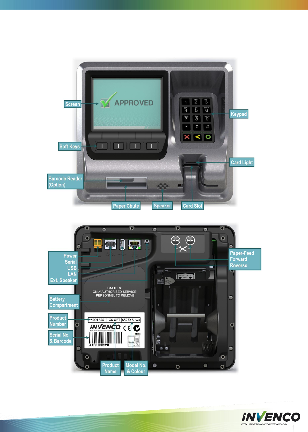
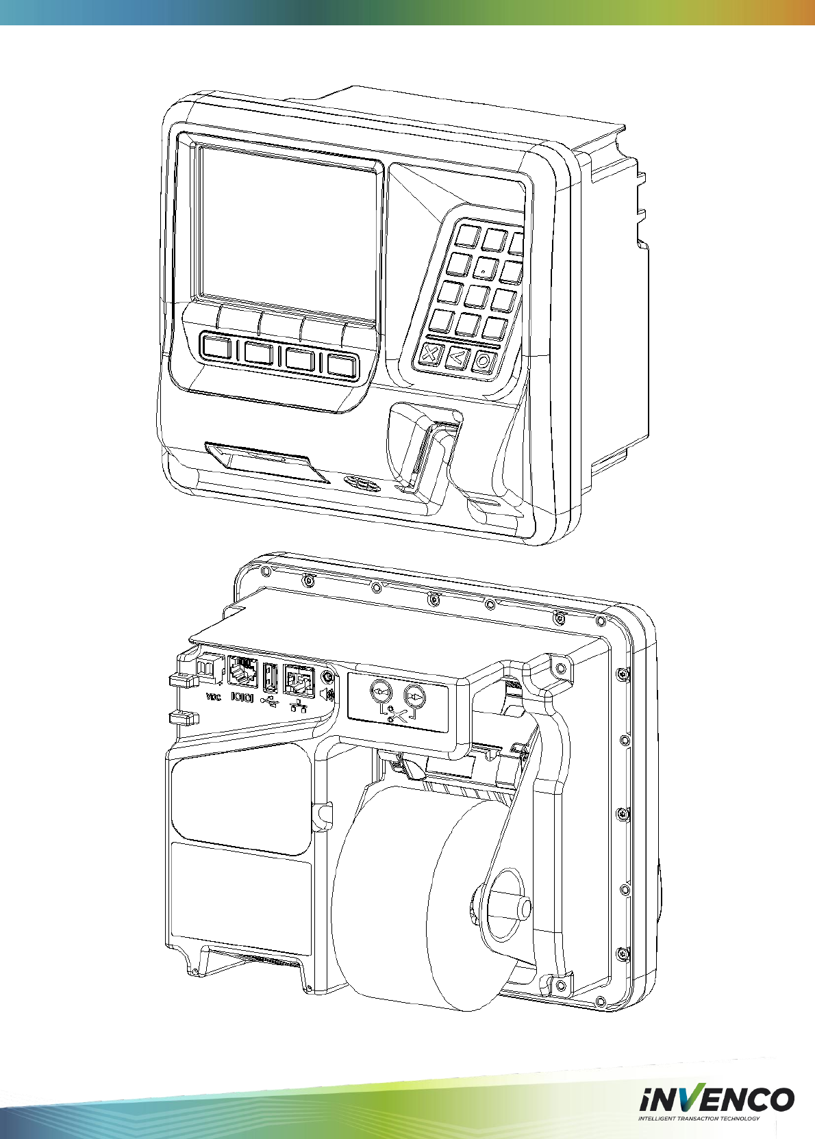
3 Product Features
3.1 Location of Features
DCV-00001 Rev 05 S2 G6 OPT Installation Guide Page 10
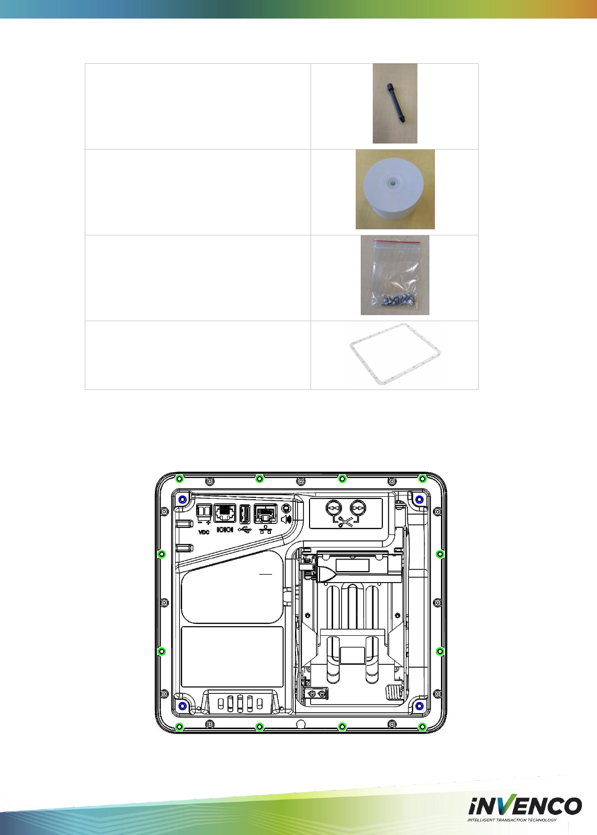
3.2 Accessories in the box
1. Spindle for Paper Roll retention
2. Paper Roll
57mm x 110mmDia, 72gsm,
thermal, top-coated, outdoor rated.
Recommended replacement paper is
NCR, P/N 0202090
3. Mounting screws
Stainless Steel, M4 x 10mm, 12 pieces
(Use Hex or Allen 3mm screw driver)
4. Mounting Gasket
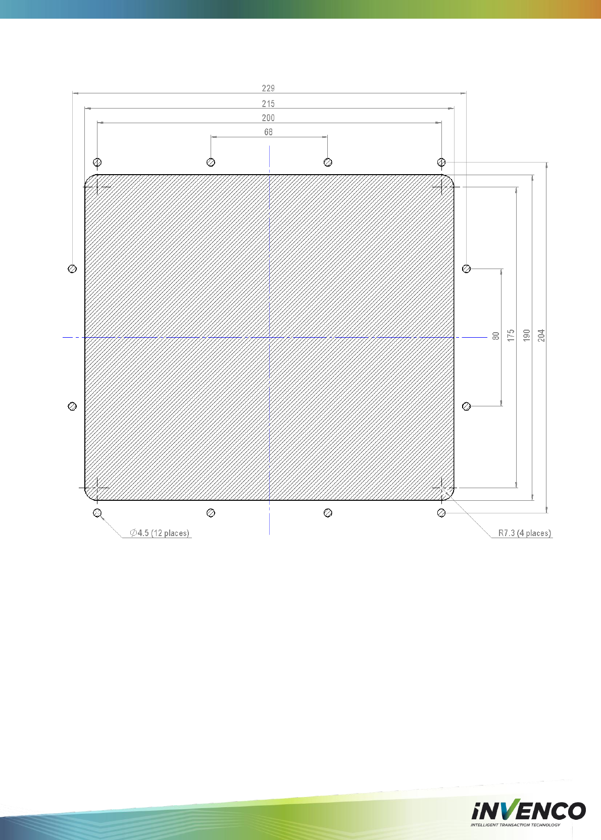
3.3 Location of Mounting Points
Green highlights are standard mounting points for a new installation.
Blue highlights are for retro-fit mounting when replacing a G5 OPT.
See the Drawings at the end of this manual for panel cut-out information.

DCV-00001 Rev 05 S2 G6 OPT Installation Guide Page 11
4 Installation
4.1 Considerations for New Enclosures
Pump manufacturers generally will not allow third parties to modify their pumps because they
have many safety certifications that can easily be invalidated. Therefore if installing into a
pump head the pump manufacturer MUST perform the necessary modifications for you.
The following factors need to be considered in designing an installation for the G6 OPT:
1. Fire
The enclosure must be designed to meet the requirements of ISO/EN 60950-1 for
FIRE ENCLOSURES.
2. ATEX (Explosive Atmospheres)
The G6 OPT has openings that prevent it being gas-tight, and consequently it must be
located away from any hazardous zone. Refer to local laws and regulations for hazardous
zones to determine a suitable mounting arrangement for the G6 OPT. The enclosure in which
the G6 OPT is mounted should also be designed to prevent a dangerous build-up of
explosive gases.
3. Security
The enclosure must provide sufficient physical security to protect the public from the
hazards within, and to reduce the possibility of tampering with the OPT.
4. Power & Data
a. The enclosure must provide mains power. The requirements are:
i. A permanently-wired connection or a socket.
ii. A protective earth connection
iii. The outlet may be switched if it is a socket, and must be switched if
it is permanently wired.
b. The enclosure must provide an Ethernet data connection. The requirements
are:
i. Capable of at least 10Mbps (preferably 100Mbps)
ii. The connection must be either a socket into which a standard
Ethernet patch cable can be connected, or a cable that is terminated
in a standard RJ45 plug suitable for direct connection into the OPT
LAN socket.
iii. Minimum cable standard should be Cat5e
c. The enclosure may provide an alternative data connection for terminals that
have optional communications modules installed. Please consult with
Invenco for what options are available.
5. Accessibility
The enclosure must be designed and mounted so that disabled persons are able to
operate the OPT.
6. Materials
The enclosure and all its components must be constructed of durable materials
suitable for the intended location.
7. Door cut-out
a. Use the wireframe drawings in Section 8 to determine the extra space
required for the front of the terminal (larger than cut-out).
b. The edge of the cut-outs should be smooth and free of burrs, and the surface
of the door around the cut-out should be clean, and planar within ± 1mm.
8. Hinging
Use the following diagrams as a guide when designing an enclosure and/or door to
house the G6 OPT. This will ensure there is a clearance between the G6 OPT
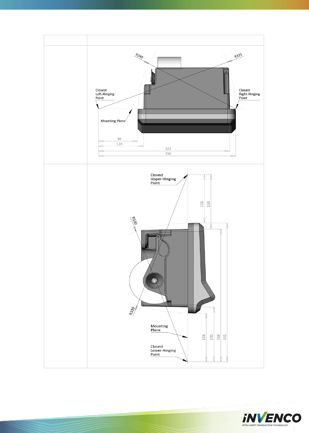
DCV-00001 Rev 05 S2 G6 OPT Installation Guide Page 12
housing and the opening. Right-side hinging is recommended by Invenco.
Description
Photo reference
Side hinging
points diagram.
Top-bottom
hinging diagram.

DCV-00001 Rev 05 S2 G6 OPT Installation Guide Page 13
9. Water-Tightness
The G6 OPT is rated for IP24 on its external parts.
The parts sitting inside the pump/pedestal enclosure are designed to reduce the
likelihood of rain splashes entering the electronics but the enclosure must provide
good protection from water.
The door should have a water seal against the enclosure, and there should be good
drainage and/or a system to reduce excessive condensation build-up and dripping.
4.2 Tools Required
The following tools are required to mount the G6 OPT:
Torx T20 screw driver (if replacing a G5 OPT)
Hex 3mm screw driver or Allen key (for mounting the G6 OPT)
Philips #1 or Flat 5mm screw driver (for conections on the power suppy)
Small adjustable spanner (for earth connections inside the cabinet)
Side cutters (to trim the cable tie(s))
Cable ties
Additional hand tools may be required if retrofitting into a non-standard existing enclosure.
WARNING – Do NOT use power tools if working on a fuel station forecourt. Any spark
could cause an explosion.
4.3 In A New Pump or Cabinet
When the doors have been pre-fabricated the G6 OPT mounting can take place:
Unpack the G6 OPT from its packing.
There will be twelve M4x8mm screws for mounting the G6 OPT.
Unlock and open the pump door
Stick the mounting gasket onto the OPT.
Peel the thin backing off to expose the adhesive.
Carefully align the gasket over the mounting surface.
Gently press the gasket down to get a good bond.
Remove the thick backing, taking care not to tear the gasket.
Hold the OPT outside the pump, and locate at least one of the top mounting screws.
Semi-tighten.
Start several of the remaining support screws around the OPT.
Check the OPT is aligned with any features on the pump door, and then tighten the
screws.
Insert and tighten all remaining screws.
See section 8.2 for a mounting diagram.
Once the physical mounting is complete, proceed to Section 4.5 for wiring instructions.
!
DCV-00001 Rev 05 S2 G6 OPT Installation Guide Page 14
4.4 Replacement of a G5 Product
The G6 OPT is designed to fit into the existing cut-out created for the G5 OPT to allow an
easy upgrade.
To simplify this process a Retrofit Kit is available for either side-mounting or top/bottom-
mounting, depending on the model of G5 OPT being replaced.
Before beginning, determine whether the existing G5 OPT is:
side-mounted (with a motorised card reader), or
top/bottom-mounted (with a manual card reader).
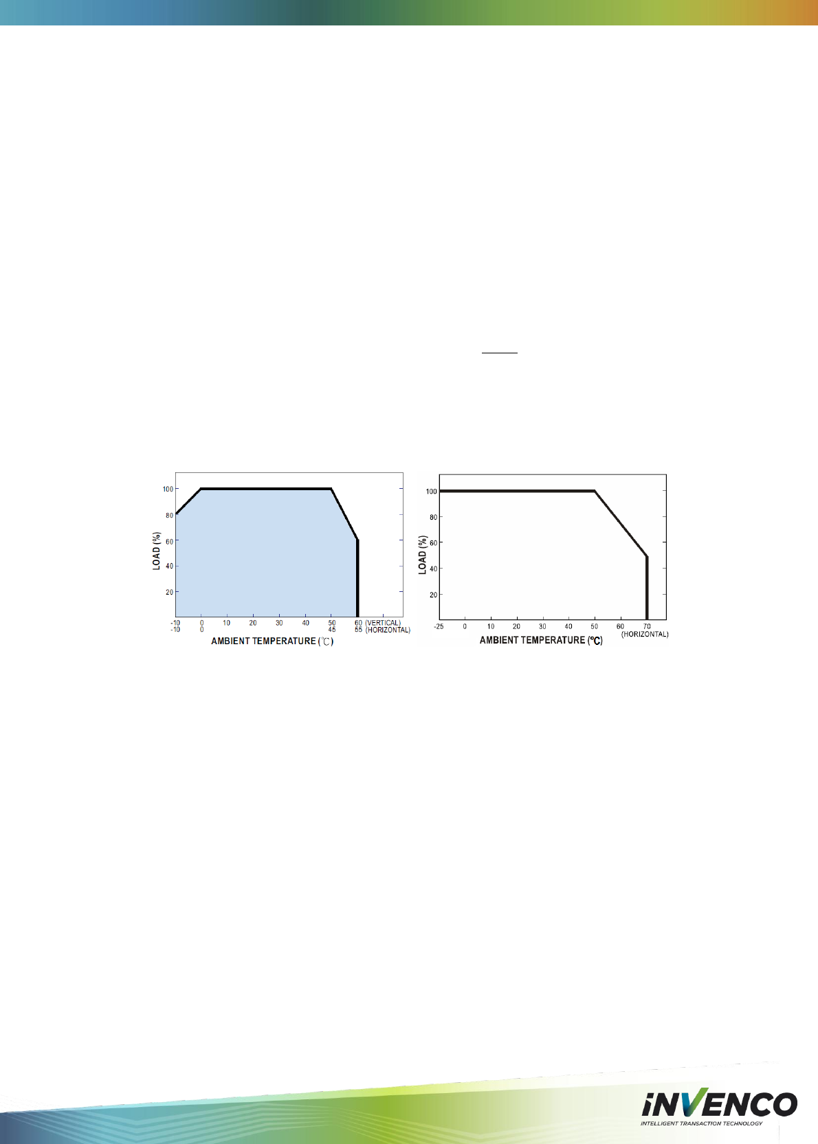
4.4.1 Power Supply Considerations
The G5 OPT was typically installed with one of the following power supplies:
Meanwell S-100-24
Franmar S-100F-24
Either of these power supplies is quite capable of driving a single G6 OPT.
Some installations may have used a single supply to drive two G5 OPTs, in which case care
needs to be paid to the maximum internal temperature of the enclosure, to avoid the power
supply becoming overloaded after de-rating for temperature.
The G6 OPT draws considerably more power than the older terminals and while two terminals
will likely operate from a single supply, Invenco does not guarantee error-free operation.
De-rating curves for typical G5 OPT (left) and recommended G6 OPT (right) power supplies.
DCV-00001 Rev 05 S2 G6 OPT Installation Guide Page 15
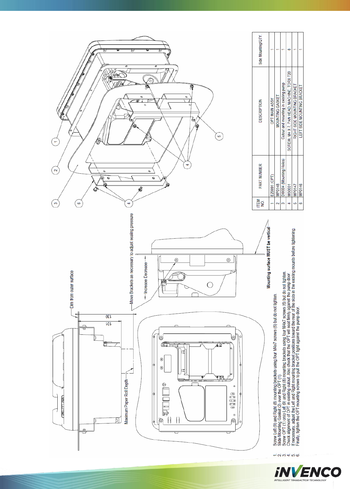
4.4.2 Selection of Retrofit Options
There are two distinct models of G5 OPT that can be replaced with a G6 OPT. Below are the
models of G5 OPT, and the list of associated parts needed for a retrofit for each.
Motorised Card Reader
(Side-Mounted)
Requires EZ0123 Retrofit Kit 1, containing:
MP0146 – Left Side Bracket
MP0147 – Right Side Bracket
MS0044 – M4 Screws (qty=8)
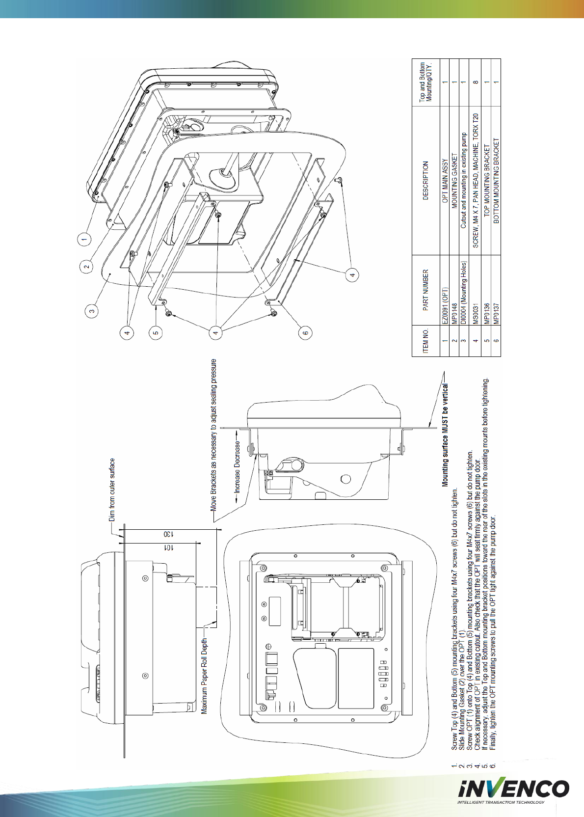
Manual Card Reader
(Top/Bottom-Mounted)
Requires EITHER EZ0124 Retrofit Kit 2, containing:
MP0136 – Top Bracket
MP0137 – Bottom Bracket
MS0044 – M4 Screws (qty=8)
OR EZ0125 Retrofit Kit 3, containing:
MP0156 – Front Escutcheon Mount
MS0044 – M4 Screws (qty=8)
4.4.3 Physical Retrofit
Step
Description
1.
Remove the existing G5 OPT.
2.
Disconnect the mains power to the power supply in the normal way.
3.
Unplug both the low-voltage connector and Ethernet connector.
Retain the Ethernet cable for later reconnection.
Disconnect the low-voltage cable from the power supply and replace it with either:
cable EK0070 (available from Invenco), or
the cable specified and supplied by your customer.
4.
Remove the plastic front bezel around the G5 OPT and discard.
5.
Loosen, and then remove the four M4 mounting screws holding the G5 OPT to the
door.
6.
Remove the G5 OPT from the back of the door, and package it for disposal or return.
7.
Open the retrofit kit and check the contents. It should have one or two brackets
(depending on kit purchased) appropriate to convert the existing to G6 OPT version,
and eight screws.
8.
Check the bracket placing – they are not symmetric.
Use the pictures below as a guide.
9.
Use four of the supplied screws to mount the bracket(s) onto the door.
Leave the screws loose so the brackets can move a little.
10.
Remove the G6 OPT from its packaging, and inspect it for damage.
DCV-00001 Rev 05 S2 G6 OPT Installation Guide Page 16
11.
The sealing gasket will be in the carton with the G6 OPT.
Place the G6 OPT face-down onto a soft clean surface.
Stick the mounting gasket onto the OPT.
Peel the thin backing off to expose the adhesive.
Carefully align the gasket over the mounting surface.
Gently press the gasket down to get a good bond.
Remove the thick backing, taking care not to tear the gasket.
12.
Insert but don’t tighten screws onto the upper bracket (top/bottom mount) or upper
positions of each bracket (side mount).
13.
Insert the remaining two screws.
14.
Tighten all four screws into the G6 OPT.
15.
The existing mounting points for the old G5 OPT should be slotted to allow for
adjustment of the mounting.
Gently press the G6 OPT onto the door to ensure the gasket forms a good seal, and
then tighten the screws holding the mounting brackets to the door.
16.
Check for a good seal around the G6 OPT, and for proper alignment of the G6 OPT
with any external features on the pump and adjust the mountings if necessary.
17.
Plug both the Ethernet and the new low-voltage cables into the correct ports on the
G6 OPT.
Use cable ties to secure the cables to the G6 OPT and to other parts of the pump
as necessary.
Ensure the cables allow the door to open and close properly and the cables are
not pinched or snagged anywhere.
18.
When the rest of the site is ready, reconnect the mains power to the power supply.
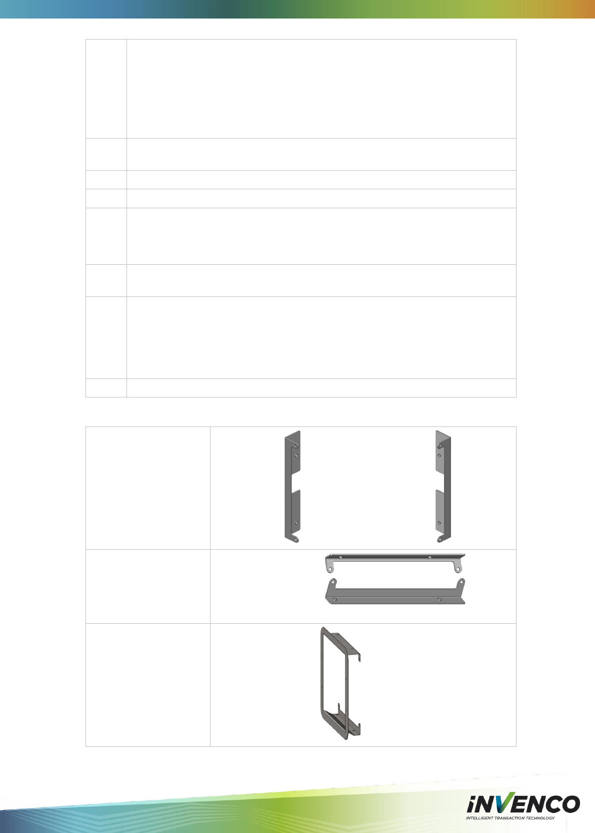
4.4.4 Retrofit Kit Parts
EZ0123
Side Mount Kit
MP0146 – Left: MP0147 – Right:
EZ0124
Top/Bottom Mount Kit
MP0136 – Top:
MP0137 – Bottom:
MP0
EZ0125
Escutcheon Mount Kit
MP0156 – Escutcheon:
DCV-00001 Rev 05 S2 G6 OPT Installation Guide Page 17
4.5 Wiring
Three connections need to be made to the G6 OPT:
1. Protective Earth
2. Ethernet LAN
3. DC Power supply
The DC power supply cable also needs to be connected to the power supply.
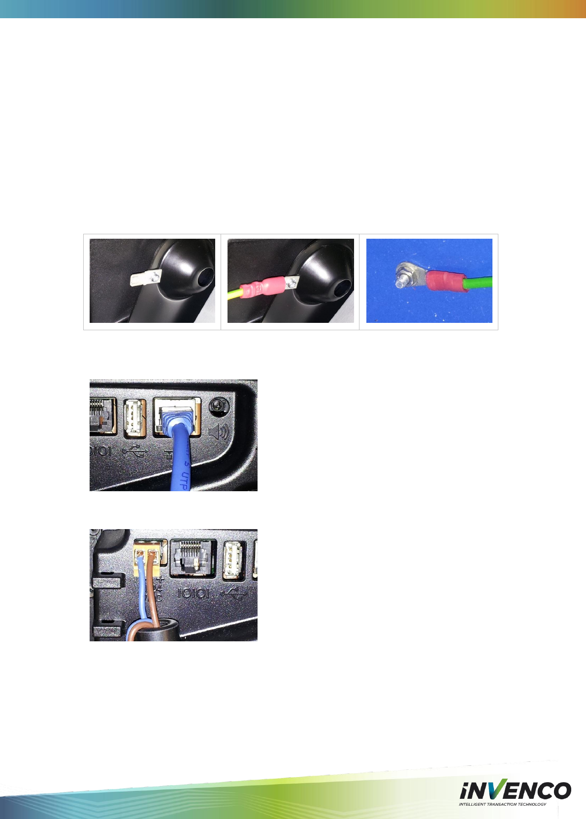
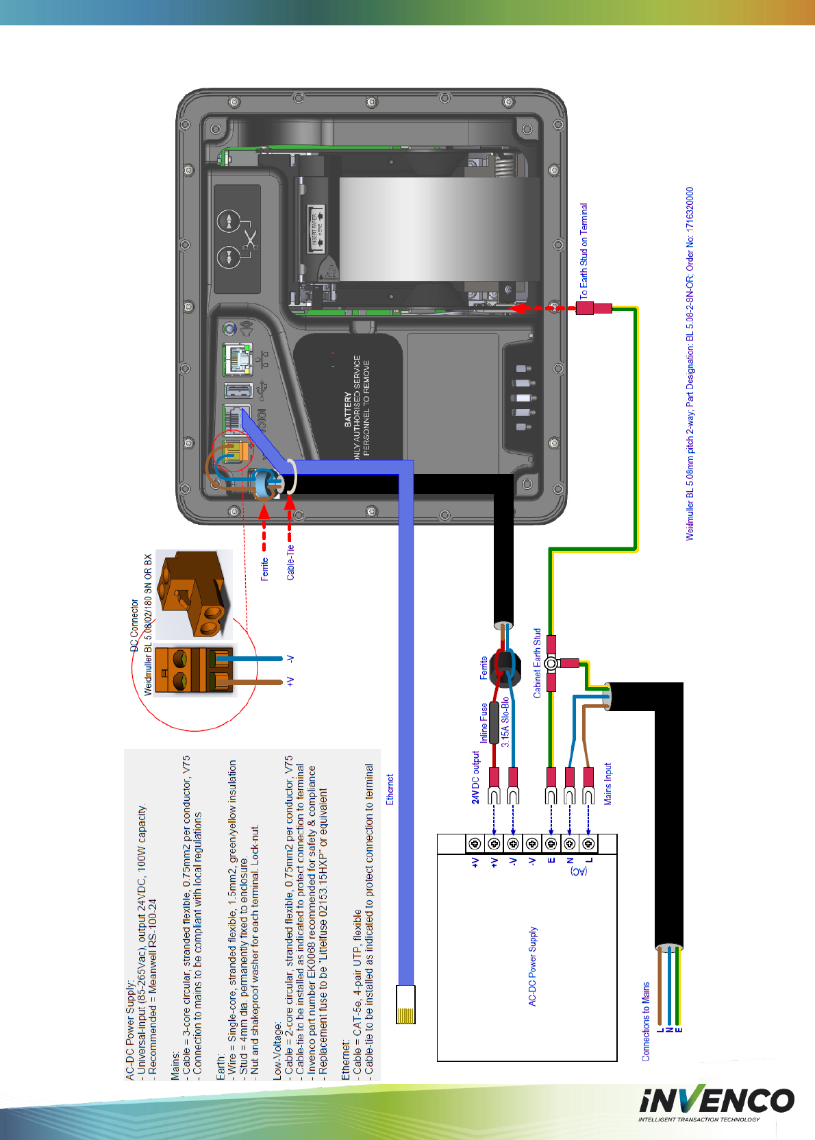
4.5.1 Protective Earth
The G6 OPT is provided with an Earth Tab.
Models with a printer have the tab mounted on the bottom of the paper-holder frame.
Models without a printer have the tab in the lower area of the rear plastic cover.
The tab must be connected to the pump (or cabinet) frame to provide protection from both
power faults and static discharges.The earth wire must be minimum 1.5mm2 and both it and
the earth stud must meet local regulations.
4.5.2 Ethernet LAN
The Ethernet cable is plugged into the correct connector on the rear of the G6 OPT:
4.5.3 DC Power Supply
The low-voltage DC Cable is plugged into the correct connector on the rear of the G6 OPT:
DCV-00001 Rev 05 S2 G6 OPT Installation Guide Page 18
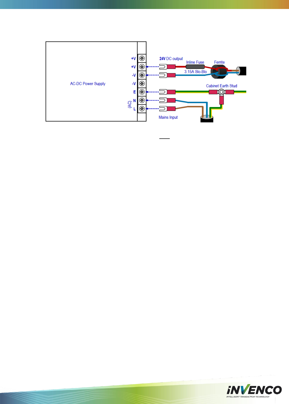
4.5.4 Main Power Supply Wiring
The other end of the low-voltage DC Cable is connected into the AC-DC power supply as
below:
Note: If retrofitting in place of a G5 OPT, the power supply may be able to be re-used. In this
case the old 24V DC cable that powered the G5 OPT must be disconnected and replaced
with the new cable for the G6 OPT.
WARNING – Once all the wiring to the power supply terminals has been completed,
install the terminal cover to prevent accidental contact with the live mains connections.
4.5.5 Wiring Completion
When all the cables have been installed, use cable ties to provide strain relief. The rear of the
G6 OPT has two plastic loops close to the connectors that are intended to assist with this.
Also ensure that all cables are tidy and cannot become snagged or pinched when the door of
the cabinet is opened and closed.
WARNING – Local regulations may also require that the installation is electrically
tested and certified BEFORE switch-on.
!
!

DCV-00001 Rev 05 S2 G6 OPT Installation Guide Page 19
5 First Power-Up
Once the installation is complete and the wiring is certified (if necessary), the main power may
be switched on.
The G6 OPT takes a couple of minutes to complete its start-up phase during which several
information screens will be presented (these vary depending on the customer).
When the terminal is trying to connect to the Ethernet LAN it will display the following screen:
If the Ethernet LAN is not operational the terminal will keep the above screen displayed.
If the terminal is successful in connecting to the Ethernet LAN it will display the following
screen and the rest of the normal start-up sequence will continue (this also varies depending
on the customer):
Follow the steps in Section 6.2 to load a fresh roll of paper.
DCV-00001 Rev 05 S2 G6 OPT Installation Guide Page 20
6 Basic Maintenance
6.1 Cleaning
The G6 OPT is designed to be easy to keep looking good. Please follow these tips to keep
your G6 OPT clean:
Use a soft cloth dampened with water for daily cleaning.
If grime builds up, use a diluted mild detergent on a soft cloth.
Take extra care when cleaning the display window – make sure the cloth is clean and
do the window before using the cloth on other parts of the terminal.
CAUTION – Do NOT use petroleum-based solvent cleaners – they may damage
surfaces making the terminal much harder to clean, and shorten the life of the parts.
CAUTION – Do NOT use a high-pressure hose to clean the terminal. The printer
chute and card reader openings will fill with water which will damage the terminal.
Over time the printer may accumulate dust and debris from the paper and cutting function.
Please do not attempt to remove dust build-up from the printer – refer cleaning to a qualified
service agent.
6.2 Paper-Roll Replacement (only for models with printer)
The G6 OPT has a precision printer mechanism that will give a long life when handled well.
After extensive testing, Invenco recommends only the following paper be used in the G6 OPT:
Manufacturer: NCR
Part Number: 020209
Paper Specification: 72GSM (74μm), Outdoor rated, Top-coated Thermal, 57mm wide.
Roll Size: 110mm dia, Core Hole size 12mm
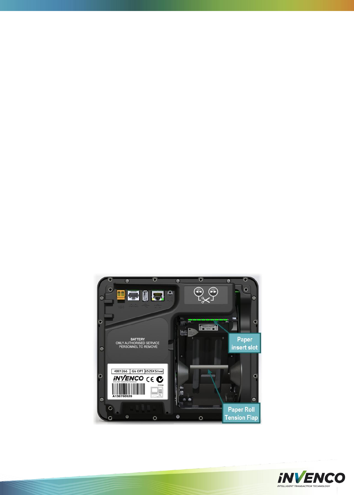
Follow the steps below to load paper into the G6 OPT. Use this full-view image as a guide:
DCV-00001 Rev 05 S2 G6 OPT Installation Guide Page 21
Step
Description
Photo reference
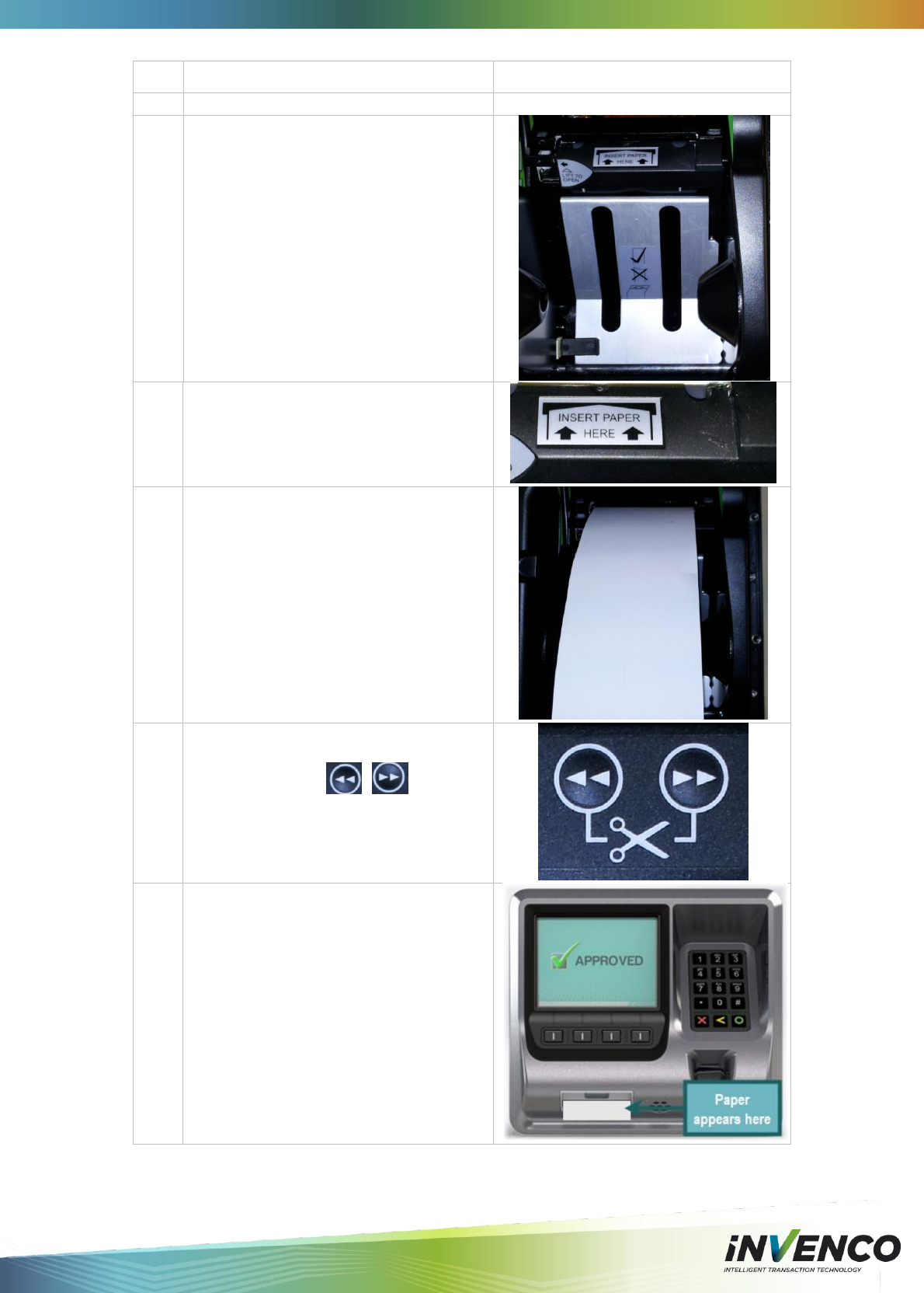
1.
Ensure the paper roll has a neat cut edge.
2.
Remove spindle from the paper holder
position
Insert roll in place – the paper tension flap
is spring-loaded so you will need to apply
some pressure.
Insert the spindle through the middle of the
roll to hold in place.
3.
Insert the cut edge of the paper into the
slot as shown in the photo opposite.
Note: Insert until the printer grips and
feeds automatically.
4.
The photo opposite shows the paper
loaded.
5.
The photo opposite shows the feed button.
Press either button to move
the paper forward or back.
Press both buttons together to cut the
paper.
6.
Feed the paper through the terminal until it
appears out the chute.
Cut the paper using both feed buttons, and
remove the cut length from the chute.
DCV-00001 Rev 05 S2 G6 OPT Installation Guide Page 22
6.3 Clearing a Paper Jam (only for models with printer)
DO NOT use sharp tools (scissors, screwdriver, etc) to clear a paper-jam. The printer is a
precision mechanism that can be easily damaged by hard sharp objects. Damage resulting
from sharp objects is not covered under warranty.
Follow the steps below to clear a paper jam.
Step
Description
Photo reference
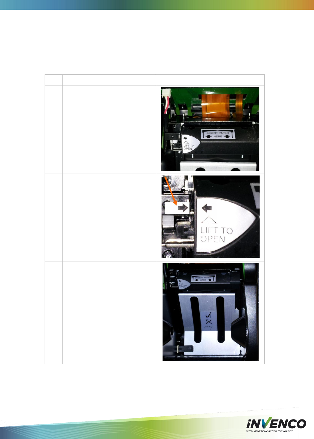
1.
Remove the paper roll if necessary.
The photo opposite shows the paper
controls.
2.
Lift the lever beside the ‘LIFT TO
OPEN’ flap.
This will release the paper guide.
3.
Any paper jammed will be visible
behind the vertical slots of the paper
roll holder.
See photo opposite.
Carefully remove any paper visible
behind these slots.
DCV-00001 Rev 05 S2 G6 OPT Installation Guide Page 23
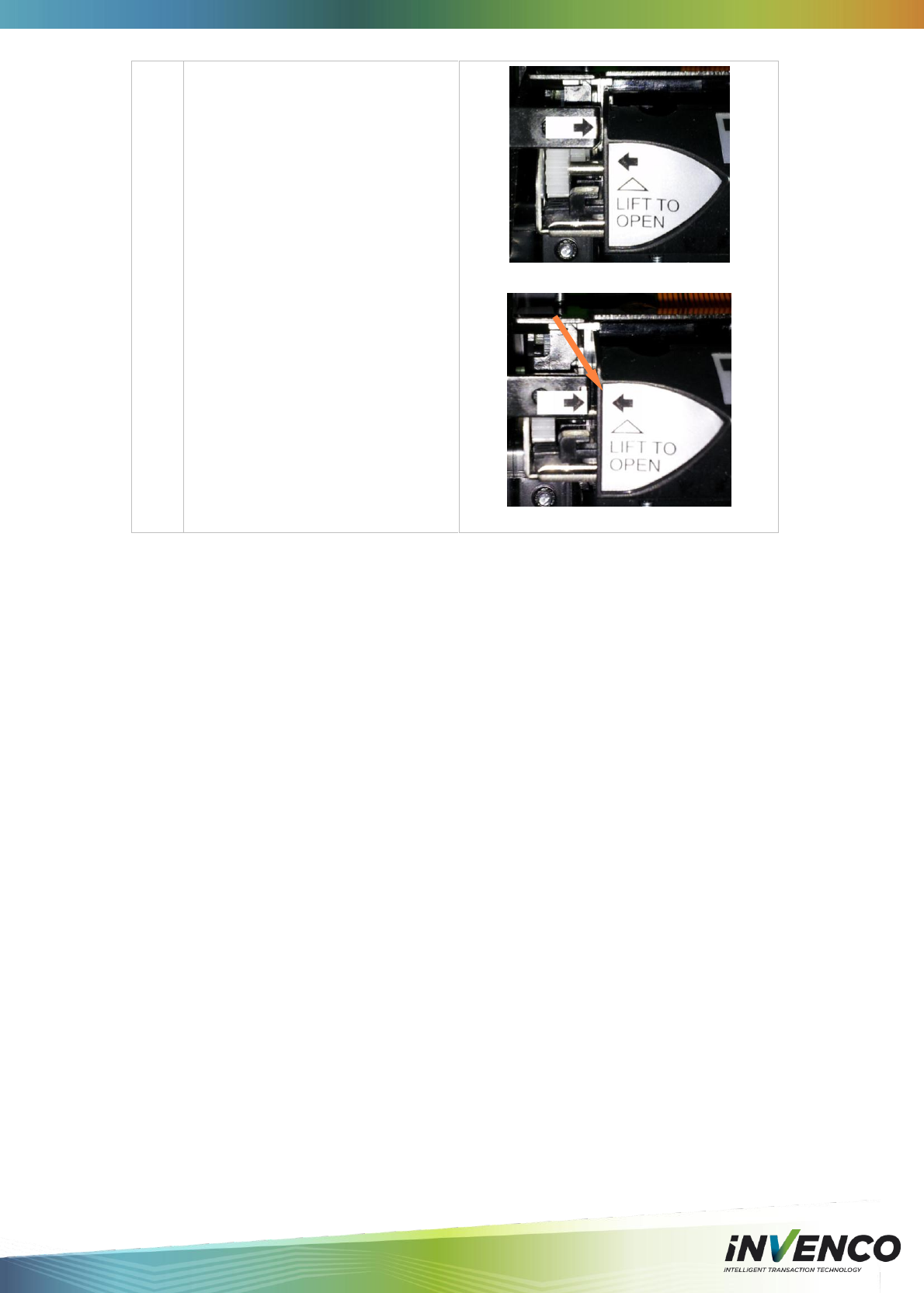
4.
Close the Printer.
Press the lever until the arrows are
aligned.
Printer unlatched
Arrows aligned

DCV-00001 Rev 05 S2 G6 OPT Installation Guide Page 24
7 Removal & Reinstallation
If the G6 OPT needs to be removed from its installation, please follow these steps:
Step
Description
1.
Ensure the terminal is not being used by a customer.
2.
Open the pump/pedestal door.
3
Reverse-feed the paper to extract it from the printer.
Remove the paper roll from the terminal.
4
Switch off the mains power to the power supply.
5
Carefully cut the cable ties holding the cables to the G6 OPT. Any other
cable ties should be left in place.
6
Unplug the LAN cable and the low-voltage power cable from the G6 OPT.
Remove the Ground wire.
7.
Loosen and remove the screws holding the G6 OPT to the door. There
will be either -
a. 12 screws around the outside of the rear plastics if the terminal was
installed new, or
b. 4 screws into a pair of adaptor brackets if it was a retrofit. The
brackets can remain in place unless they cause interference, or if
you need to replace them as well.
8.
There is a soft foam gasket that seals the G6 OPT to the outside face of
the door, and over time this is likely to stick to the door.
Use gentle hand pressure to push the G6 OPT off the door, while holding
the terminal on the outside to prevent it falling.
9
Place the G6 OPT into suitable packaging for transport or perform the
necessary maintenance.
10.
If the sealing gasket was stuck to the door, clean off any pieces of gasket
material with a soft scraper, being careful not to damage the door surface.

DCV-00001 Rev 05 S2 G6 OPT Installation Guide Page 25
Follow the steps below to reinstall a G6 OPT:
Step
Description
1.
If you are swapping one G6 OPT for another, proceed to step 2.
To prepare the terminal, you will need to remove the existing sealing
gasket and replace it with a new one.
a. The gasket is strongly fixed to the terminal and must be scraped off
with a soft scraper.
b. Use isopropyl alcohol to remove any remaining adhesive.
c. Apply a new gasket by removing the THIN paper backing and
carefully positioning it over the G6 OPT rear cover.
Align the gasket before pressing down gently all around.
d. Gently remove the cardboard backing just before you reinstall the
terminal.
2.
Place the G6 OPT carefully into the cut-out in the door, and align it with
the screw-holes or with the brackets if this is a retrofit.
3.
Start the screws into the G6 OPT but don’t tighten them.
4
Make sure the G6 OPT is properly aligned, and then tighten the screws.
a) If this is a retrofit and you are reinstalling the brackets, press the G6
OPT onto the door before tightening the screws, to ensure a good
seal.
b) If this is a retrofit and you are only replacing the G6 OPT, make sure
the terminal is not twisted in the cut-out, and lines up with external
features of the door/pump before tightening the screws.
5
Plug in the LAN cable and the low-voltage power cable, and reconnect
the Ground wire.
6.
Use new cable ties to secure the cables to the G6 OPT.
Ensure that the cables are tied so that they will not be snagged or
pinched when the door is opened and closed.
7.
Switch on the mains power supply and check that the G6 OPT powers up
correctly.
8.
Replace the paper roll in the G6 OPT and feed the paper into the printer.
9.
Check that the G6 OPT has come online correctly, and then close the
door.
DCV-00001 Rev 05 S2 G6 OPT Installation Guide Page 26
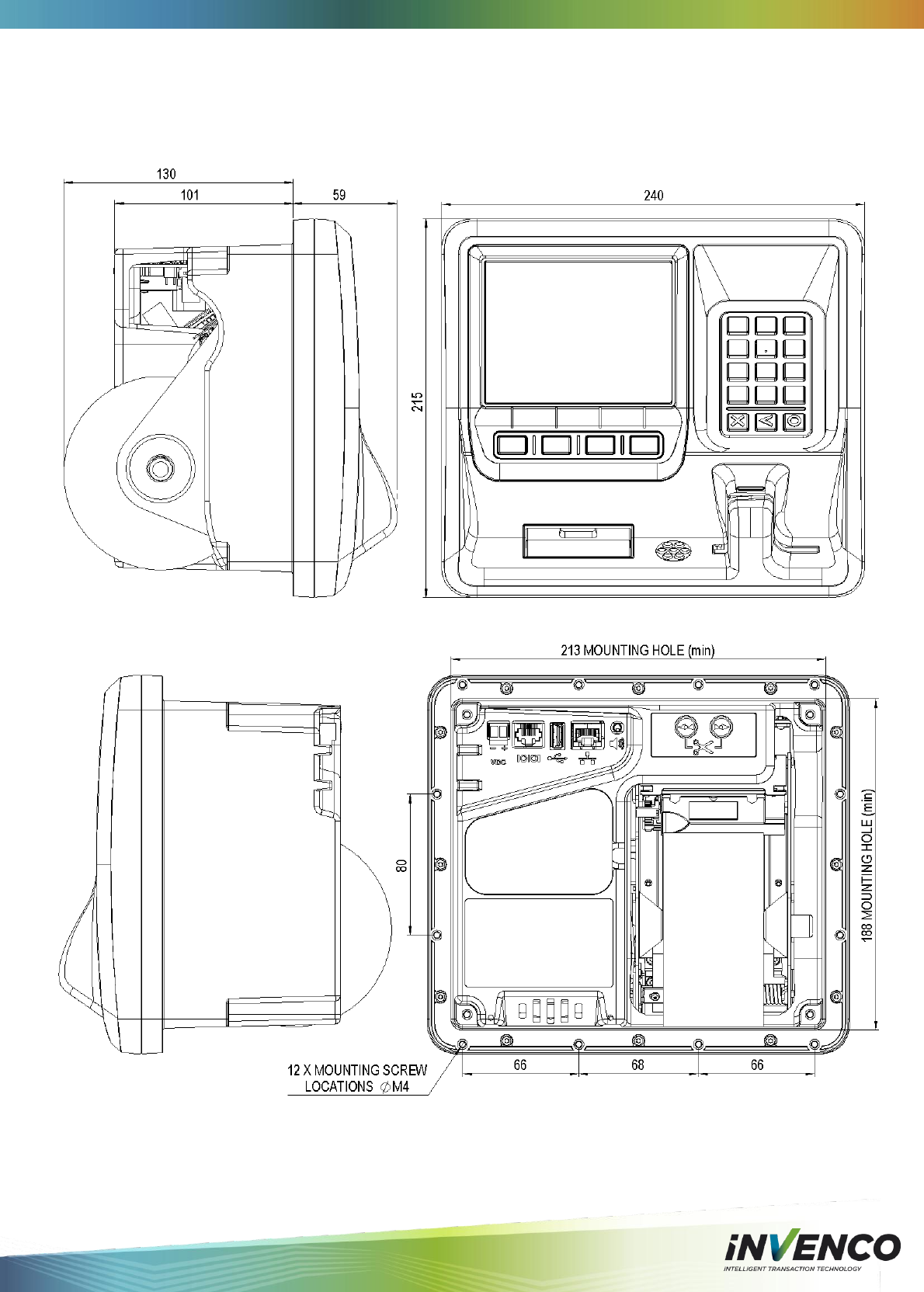
8 Drawings
8.1 Dimensions
DCV-00001 Rev 05 S2 G6 OPT Installation Guide Page 27
DCV-00001 Rev 05 S2 G6 OPT Installation Guide Page 28
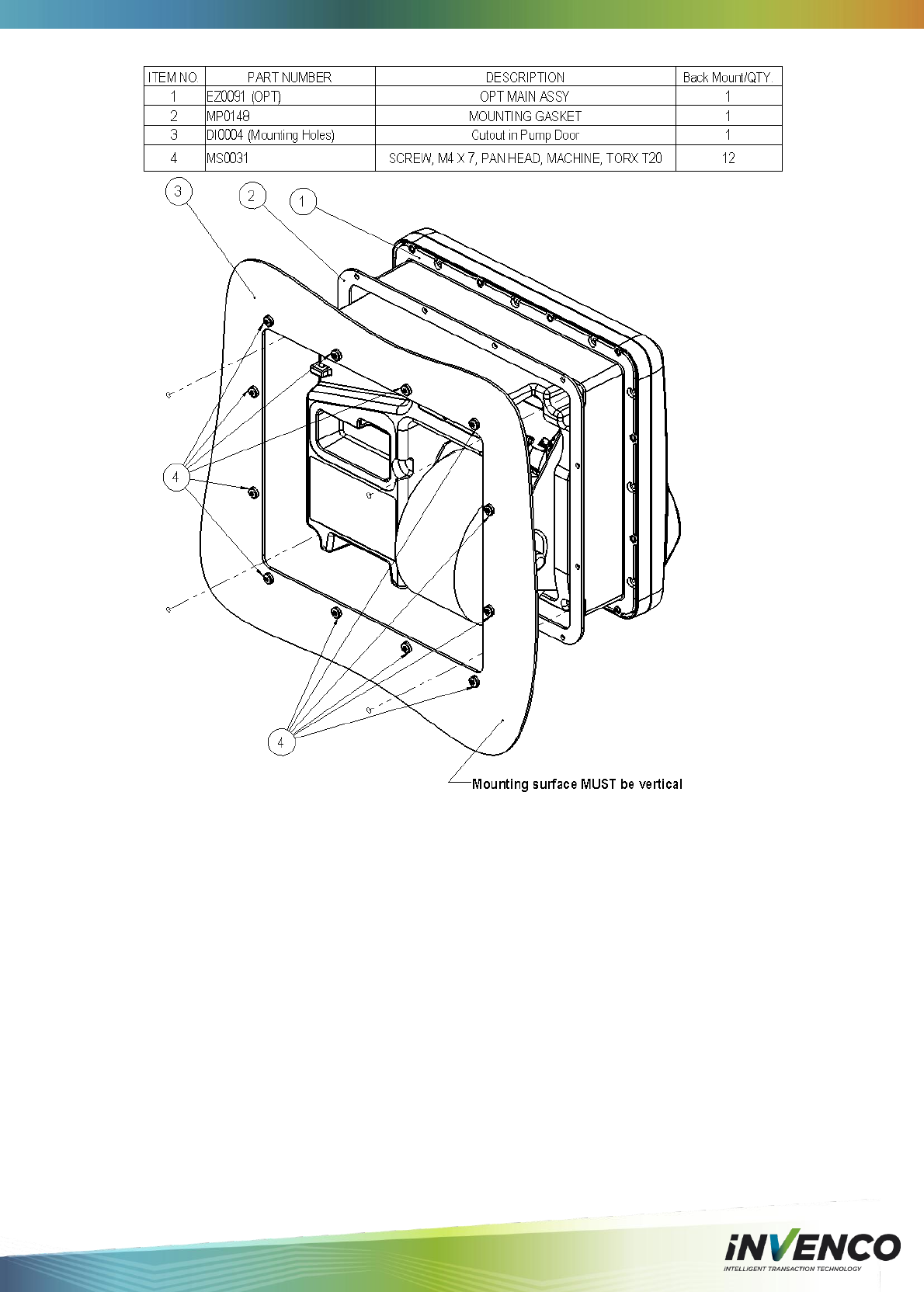
8.2 Mounting – New Installation
Note: This drawing is not to scale – Do NOT use as a template.
DCV-00001 Rev 05 S2 G6 OPT Installation Guide Page 29
DCV-00001 Rev 05 S2 G6 OPT Installation Guide Page 30
8.3 Retrofit for G5 OPT with Motorised Card Reader
DCV-00001 Rev 05 S2 G6 OPT Installation Guide Page 31
8.4 Retrofit for G5 OPT with Manual Card Reader
DCV-00001 Rev 05 S2 G6 OPT Installation Guide Page 32
9 Typical Wiring

DCV-00001 Rev 05 S2 G6 OPT Installation Guide Page 33
10 Notes

DCV-00001 Rev 05 S2 G6 OPT Installation Guide Page 34

Item 8 - User Manual DCV-00001 Rev 05 S2 G6 OPT Installation GuideVersion 1.0
Page 35
© 2015 Invenco Group Ltd. All rights reserved.
No part of this document may be copied or reproduced in any form without prior
written consent of Invenco Group Ltd.
The information in this document is subject to change without notice and should
not be construed as a commitment by Invenco Group Ltd. Invenco Group Ltd
has taken great effort to verify the accuracy of this document but assumes no
responsibility for any technical inaccuracies or typographical errors.
Auckland
Ph: + 64 9 369 2900
111 Franklin Rd
Freemans Bay
Auckland 1011
New Zealand
Asia
Ph: +60 3 2785 1888
Suite 2B-1-1, Level 1, Block 2B
Plaza Sentral
Jalan Stesen Sentral 5
50470 Kuala Lumpur
Malaysia
www.invenco.com