Invenco Group G7UPC Payment terminal with RF Card Reader User Manual Manuals
Invenco Group Ltd Payment terminal with RF Card Reader Manuals
UserManual.wiki
>
Invenco Group
>
G7UPC User Manual
Manuals
Navigation menu
Upload a User Manual
Namespaces
Wiki Guide
HTML
PDF
Info
Views
User Manual
Discussion / Help
Navigation
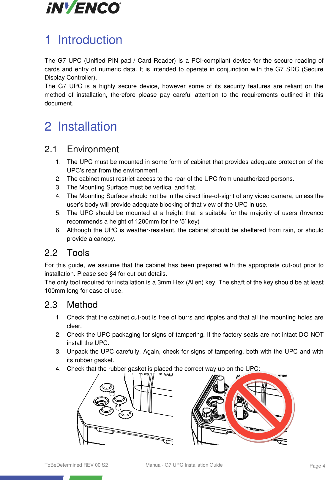
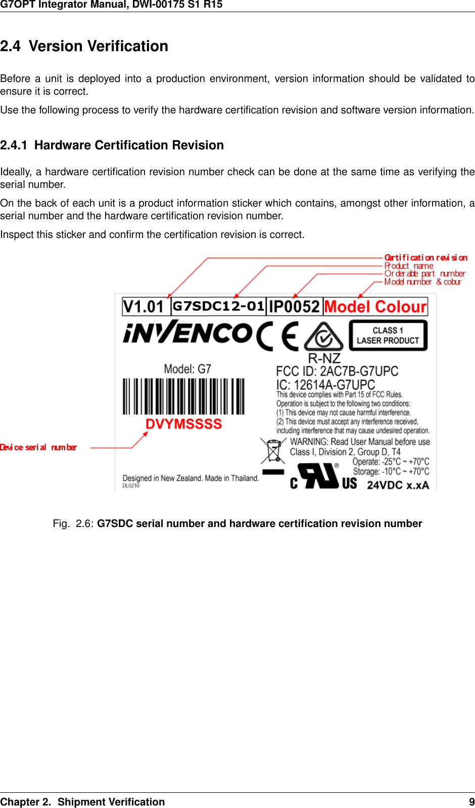
![CHAPTER 1IntroductionThis document describes instructions, policies and procedures, for integrators of Invenco Group’ssecurity products into larger systems (e.g. into payment terminals for petrol station forecourts). Itssecurity classification reflects that it is available only to parties approved by Invenco; anyone inpossession of it is responsible for maintaining confidentiality of the manual itself and all informationcontained herein.1.1 Important Related DocumentsInvenco’s security products manage sensitive information. Accordingly the company imposes certainstrictures which apply even while Invenco does not have custody of its products. These stricturesmust be adhered to by integrators (and their agents such as service technicians – Invenco makes nodistinction for the purpose of responsibility). They are compiled separately into [G7INTSEC] which isavailable publicly; they are not the focus of this document.Similarly this document is not a developer manual: it does not duplicate information essential toprogrammers writing software to work with Invenco’s products. Software development is a challengingtask for integrators; Invenco provides extensive support for it. Integrators should approach the companyfor resources and assistance.1.2 Important Information on Radio Frequency ComponentsThis section applies to the G7UPC which includes a Near Field Communication (NFC) module andantenna for use with contactless cards.1.2.1 FCC Compliance StatementsTHIS DEVICE COMPLIES WITH PART 15 OF THE FCC RULES. OPERATION IS SUBJECT TO THEFOLLOWING TWO CONDITIONS:1. THIS DEVICE MAY NOT CAUSE HARMFUL INTERFERENCE, AND2. THIS DEVICE MUST ACCEPT ANY INTERFERENCE RECEIVED, INCLUDINGINTERFERENCE THAT MAY CAUSE UNDESIRED OPERATION.THE GRANTEE IS NOT RESPONSIBLE FOR ANY CHANGES OR MODIFICATIONS NOTEXPRESSLY APPROVED BY THE PARTY RESPONSIBLE FOR COMPLIANCE. SUCHMODIFICATIONS COULD VOID THE USER’S AUTHORITY TO OPERATE THE EQUIPMENT.Note: This equipment has been tested and found to comply with the limits for a Class B digital device,pursuant to part 15 of the FCC Rules. These limits are designed to provide reasonable protectionagainst harmful interference in a residential installation. This equipment generates uses and can radiateradio frequency energy and, if not installed and used in accordance with the instructions, may causeDWI-00175 S1 R15 1](https://usermanual.wiki/Invenco-Group/G7UPC/User-Guide-3224022-Page-4.png)
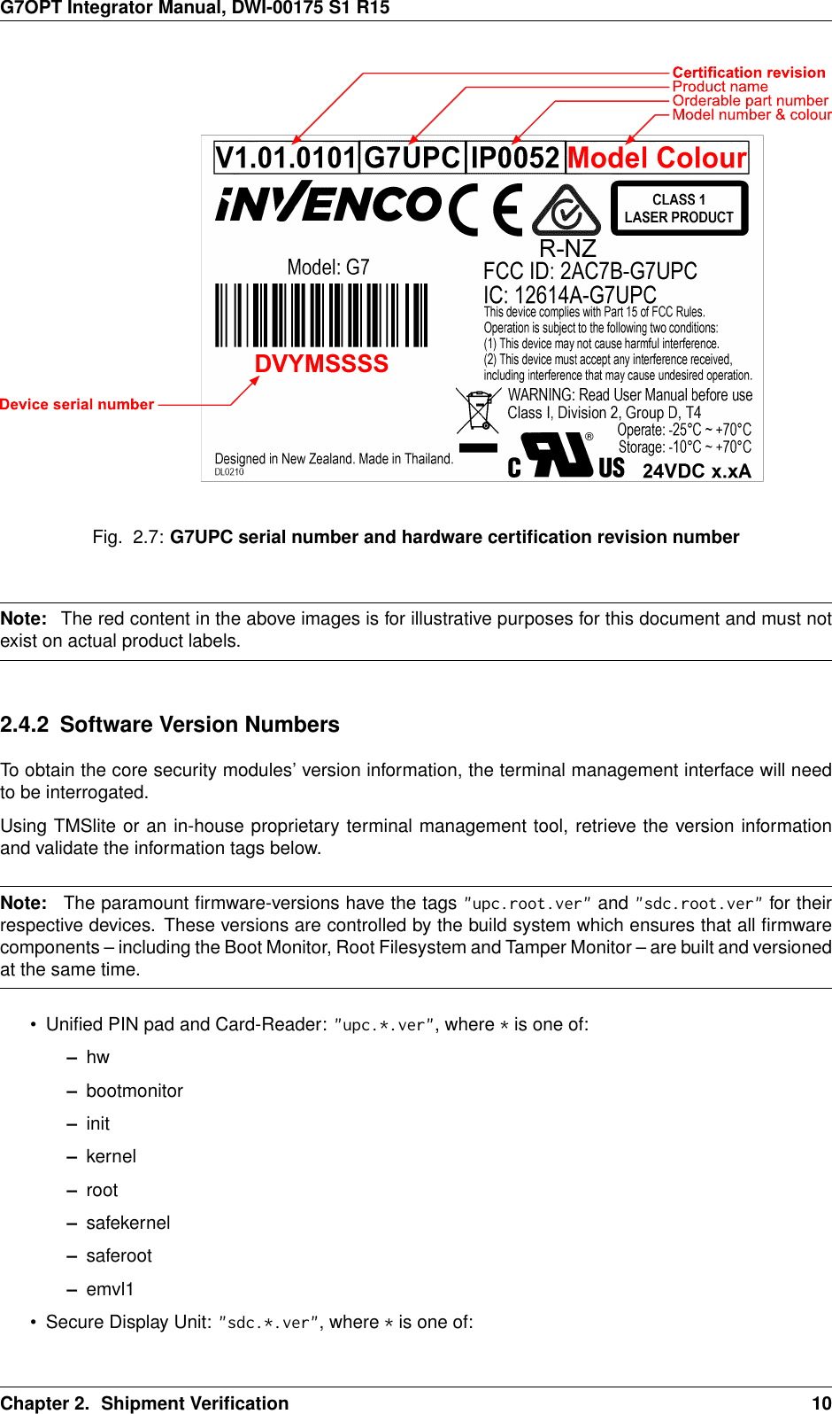
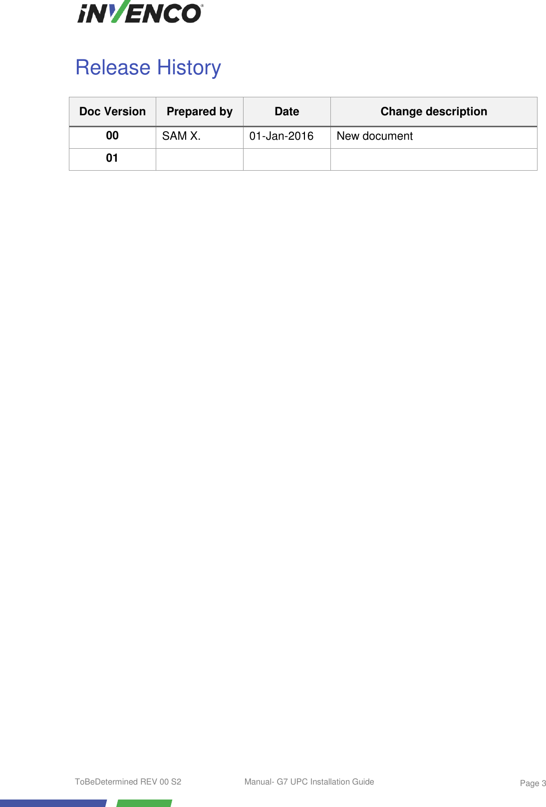
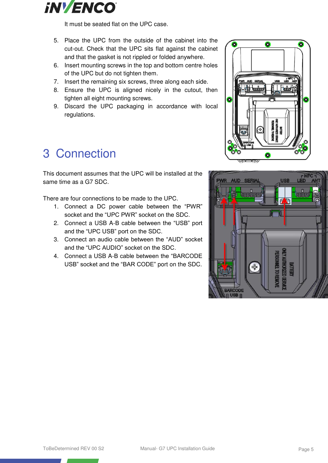
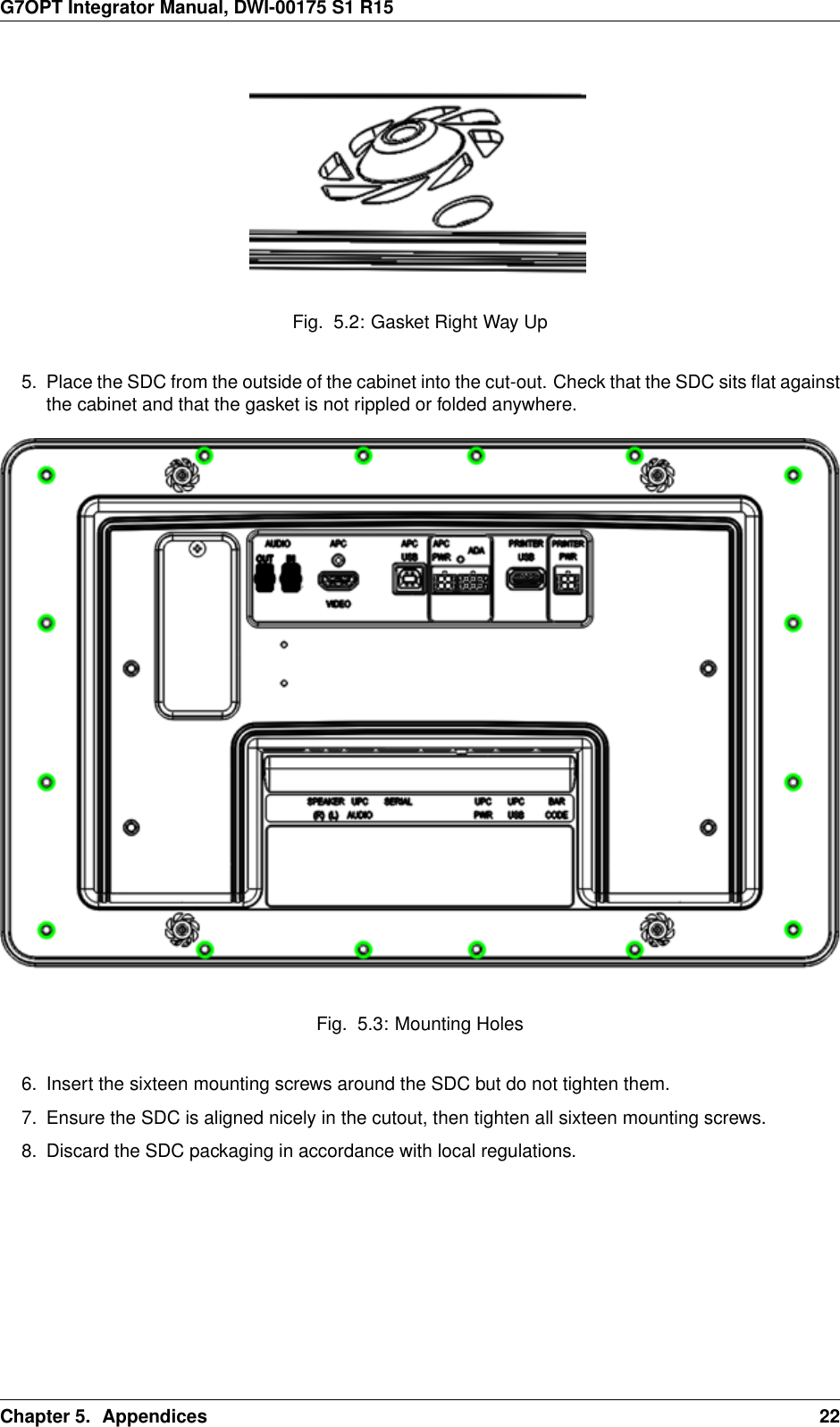
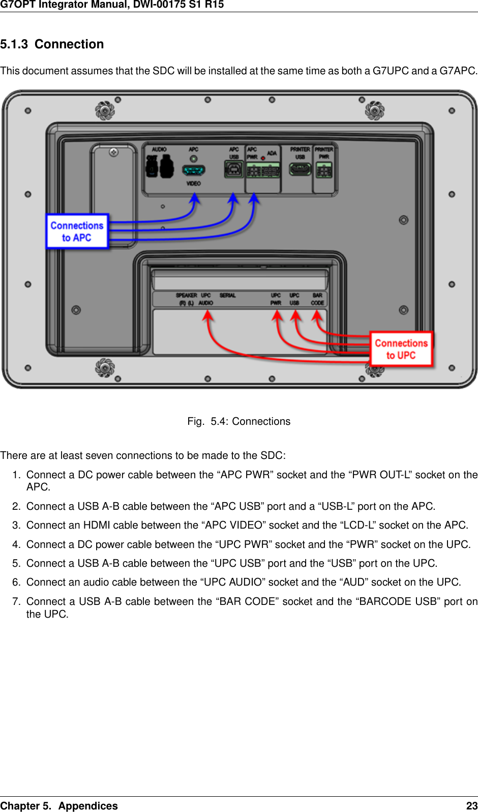
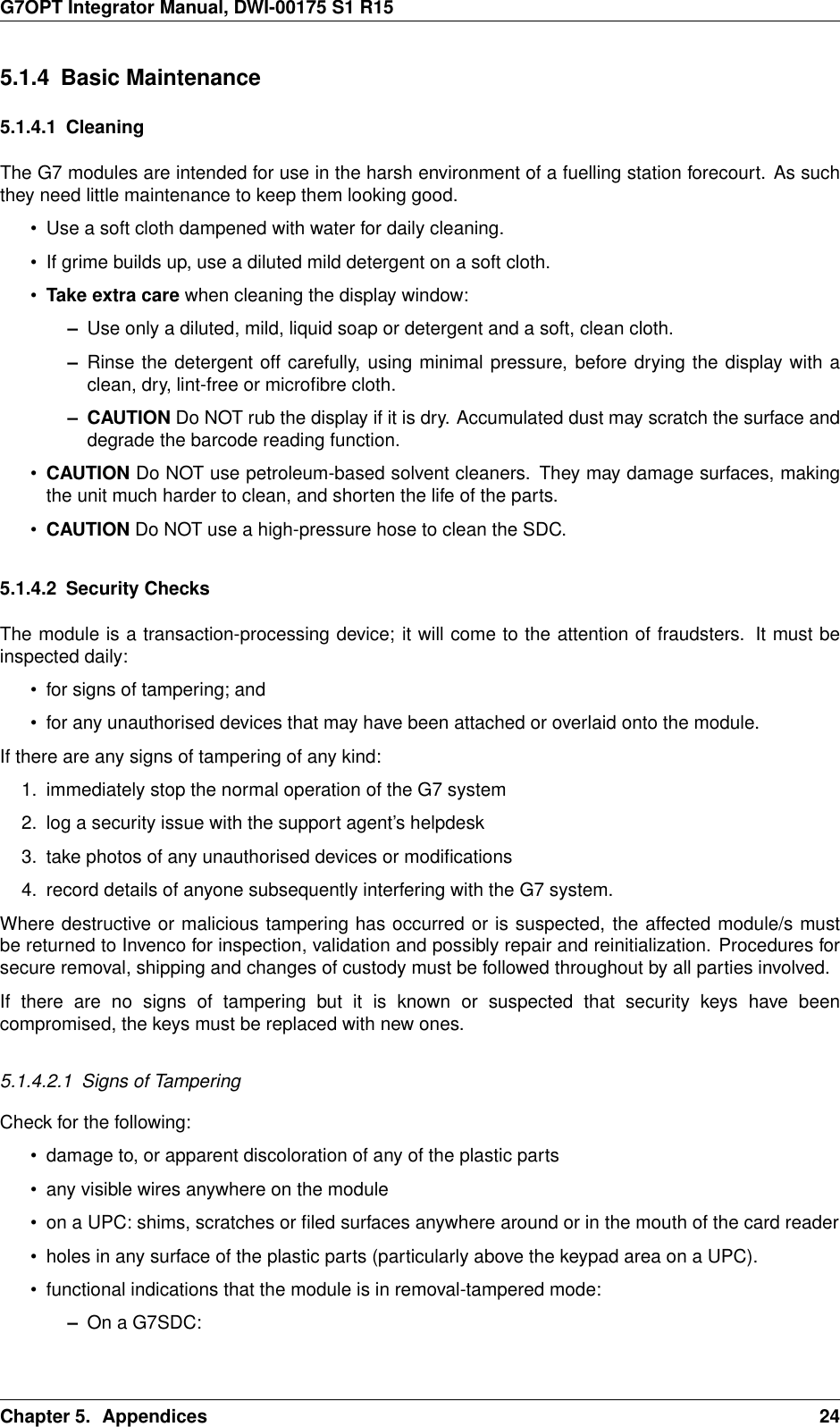
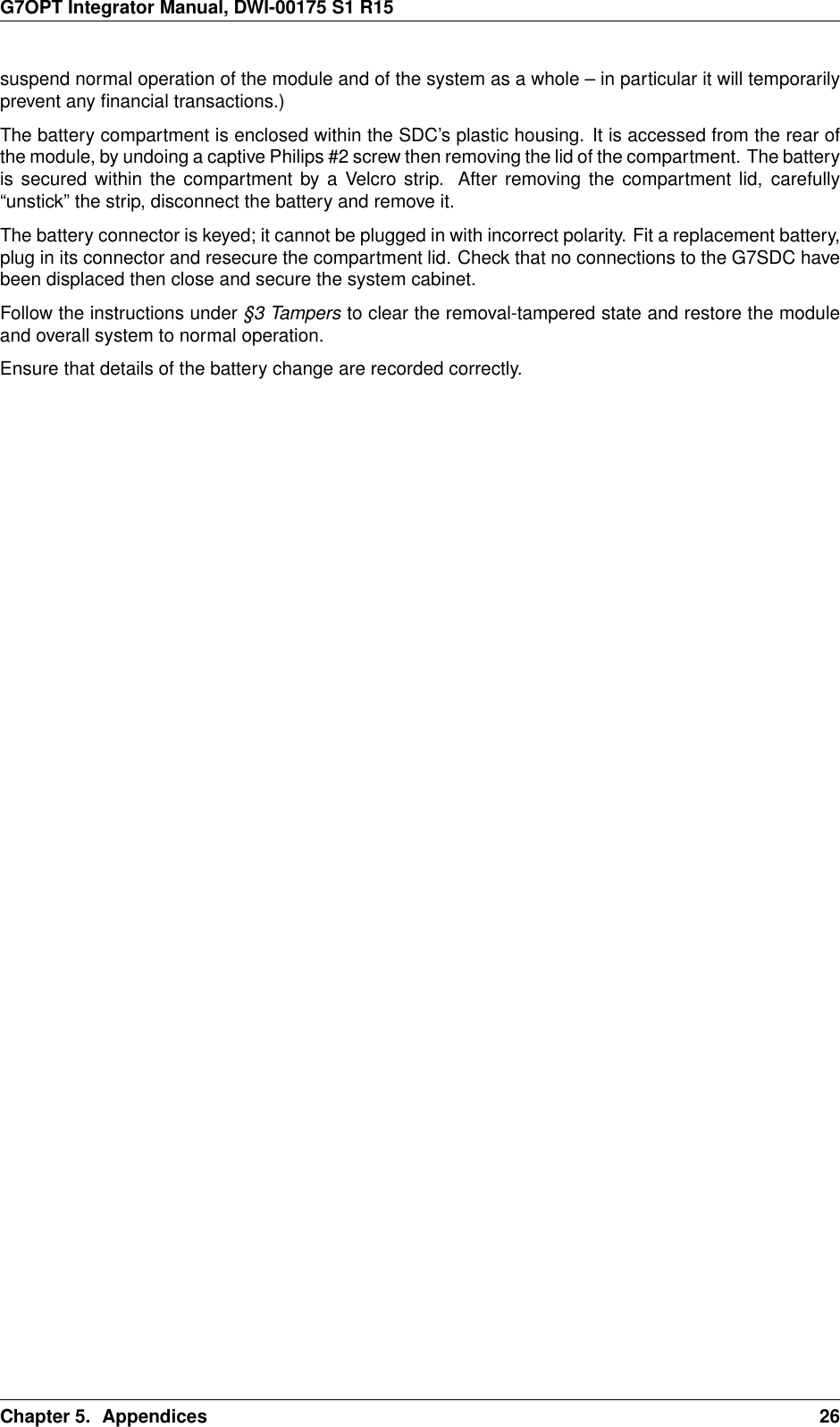
![G7OPT Integrator Manual, DWI-00175 S1 R153.2.1 Installation with Removal-Tamper Sensors1. Obtain access to where the unit will be integrated into its system, paying attention to authorisationby accredited staff.2. Obtain custody of the unit and any documentation, cables and other ancillary products.Adhere to the requirements for custody change, unpacking, etc. in [G7INTSEC] as appropriate.3. Mount the unit, and others which it will be connected to, in accordance with the integrator’sinstructions and those of Invenco.See §5.1 G7SDC Installation Guide or §5.2 G7UPC Installation Guide for details. If instructionsconflict, Invenco’s must take precedence; failure to observe this may compromise the unit’ssecurity and/or void its standards certification.4. Connect the unit to all others that it is being integrated with.Tamper connections will vary according to whether the Invenco unit is integrated standalone or inan Invenco housing. Both methods are described in the appended installation guides. Removaltampers are likely to have been connected already in the course of mounting the unit; additionalconnections for tampers should be unnecessary.3.2.2 Removal-Tamper Clearing and Promotion to Normal Operation1. The unit is now integrated into the system; it is in the removal-tampered state. Power it up andverify that restricted-mode operation is possible.In removal tampered state:• the UPC will display a slow (once a second) red flashing LED• the SDC will display a “removal tamper” error message2. To clear the removal-tampered state and enable the unit for normal operation requires acryptographically authenticated challenge and response between it and an authorisation device.This transaction is performed under dual control, the two parties being a field engineer and acontrol-centre operator.(a) The field engineer must first request a challenge token from the integrated unit. This isachieved by:i. Connect the terminal to the workstation running TMSlite.ii. (First time only) Click Add, enter the terminal connection details, then click OK.Fig. 3.3: Terminal connection details.iii. Select the terminal from the left-hand list, then click Connect.Chapter 3. Tampers 15](https://usermanual.wiki/Invenco-Group/G7UPC/User-Guide-3224022-Page-18.png)

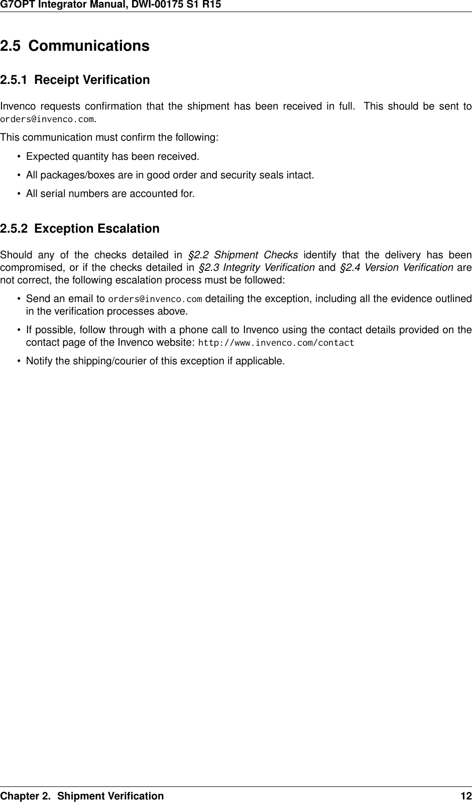
![G7OPT Integrator Manual, DWI-00175 S1 R15Revision 04, 2016-10-17• Removed explicit reference to [G7NI]; integration should focus on the higher-level SDK andSocketTAL.• Update “Shipment Verification” chapter.• Update “Tampers” chapter.• Add “Key Injection” chapter.Revision 03, 2016-07-15• Corrected “Attached Devices and/or Overlays” heading depth in installation guides.• Move document history to back.Revision 02, 2016-06-24• Restructured, moving installation guides into appendices.• Incorporated former standalone G7OPT Shipment Verification doc as a chapter.Revision 01, 2016-05-30• Renamed to G7OPT Integrator Manual, split into one file per chapter.• Captured drafts of UPC Installation Guide and SDC Installation Guide into reST andincorporated.Revision 00, 2016-02-29• Initial release; imported into reST from G7OPT Integrators Implementation Guide.Chapter 7. Document History 46](https://usermanual.wiki/Invenco-Group/G7UPC/User-Guide-3224022-Page-49.png)