Invengo Information Technology XC-RF812 UHF RFID Reader User Manual
Invengo Information Technology Co., Ltd. UHF RFID Reader Users Manual
Users Manual

User’s Manual
XC-RF812 Reader
Invengo Information Technology Co., Ltd.
Thank you for using Invengo’s RFID products!
We are glad that you’ve chosen XC-RF812 UHF RFID reader.
We hope our product will make your daily tasks at work easier!
Thank you for using Invengo’s RFID products!
We are glad that you’ve chosen XC-RF812 UHF RFID reader.
We hope our product will make your daily tasks at work easier!
Foreword
This manual applies to the XC-RF812 reader.
This manual provides information on product application, maintenance, repair and other
features for users and maintenance personnel of the products.
Current version of this manual is V1.1, with revision record as follows:
9 June 2014 V1.0
10 March 2016 V1.1
10 May 2016 V1.2
or trademark belongs to Invengo.
All introduction and explanation on the product features, as well as the functions and other
related information, written in this manual, are the latest and accurate as at time of print. The
company reserves all rights to make any correction or amendment to this manual without
prior notice, and shall bear no responsibility for these actions.
Main content
Product Overview
Performance Parameters
Dimensions and Weight
Structural Features and Working Principals
Installation and Troubleshooting
Operating RFID Demo
Routine Maintenance, FAQs and Troubleshooting
Transport and storage
Packaging and Un-packing
After-sale Service and Contact

Safety Instructions
Warning sign
Improper handling may cause damage to health.
Improper handling may result in equipment damage.
Notication sign
If ignored, it may result in unsuccessful operation.
If ignored, it may result in undesired effect.
Content
1 Product Overview ......................................................................... 1
1.1 Introduction .................................................................................................... 1
1.2 Application scope .......................................................................................... 1
1.3 Model description .......................................................................................... 2
1.4 Operating conditions ................................................................................................ 2
1.5 Operating Environment ................................................................................. 2
1.6 Safety and protective measures ................................................................... 2
2 Performance Parameters ............................................................. 3
2.1 Features .......................................................................................................... 3
2.2 Technical parameters .................................................................................... 3
3 Dimensions and Weight ............................................................... 4
3.1 Dimensions ..................................................................................................... 4
3.2 Weight ............................................................................................................. 4
4 Structural Features and Working Principals ..............................5
4.1 Overall structure and working principals .................................................... 5
4.2 Bottom panel description .............................................................................. 5
4.2.1 Panel ...................................................................................................................... 5
4.2.2 LED panel ............................................................................................................. 6
4.3 PC and API requirements .............................................................................. 7
4.3.1 PC .......................................................................................................................... 7
4.3.2 API ........................................................................................................................ 7
5 Installation and Troubleshooting ................................................ 8
5.1 Installation tips ............................................................................................... 8
5.2 Installation conditions ................................................................................... 8
5.2.1 Connecting the XC-RF812 ................................................................................... 8
5.2.2 Apply power to the XC-RF812 ............................................................................. 9
5.3 Troubleshooting ............................................................................................. 9
5.4 Acceptance ................................................................................................... 10
5.4.1 Structure acceptance ........................................................................................... 10
5.4.2 Performance Acceptance ..................................................................................... 10
6 Operating RFID Demo ................................................................ 11
6.1 Preparation before operating RFID Demo ..................................................11
6.2 Demo software application environment ....................................................11
6.3 Installing RFID Demo ....................................................................................11
6.4 Demo Software Operation ........................................................................... 15
6.4.1 Start screen .......................................................................................................... 15
6.4.2 Reader Conguration .......................................................................................... 17
6.4.3 Scan conguration .............................................................................................. 18
6.4.4 Issue mode conguration .................................................................................... 19
6.4.5 Issue tag operation .............................................................................................. 21
7 Routine Maintenance, FAQs and Troubleshooting ................. 23
7.1 Routine maintenance ................................................................................... 23
7.2 FAQs and troubleshooting .......................................................................... 23
8 Transport and storage................................................................ 24
8.1 Transport Requirement................................................................................ 24
8.2 Storage Requirement ................................................................................... 24
9 Packaging and Un-packing........................................................25
9.1 Packaging ..................................................................................................... 25
9.2 Un-packing.................................................................................................... 25
10 After-sale Service and Contact ............................................... 26
10.1 After-sale service ....................................................................................... 26
10.1.1 Reader information ........................................................................................... 26
10.1.2 Computer Information ...................................................................................... 26
10.2 Other matters.............................................................................................. 27
User’s Manual
XC-RF812 Reader 1
1 Product Overview
1 Product Overview
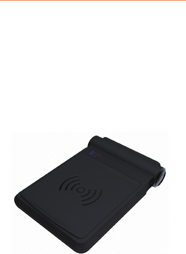
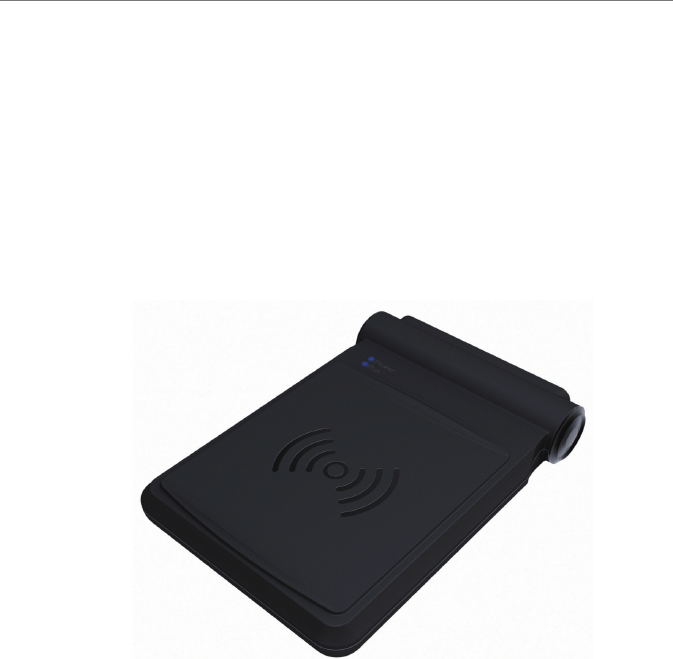
1.1 Introduction
The XC-RF812-type reader is a high performance UHF reader with a built-in
antenna. The reader supports ISO18000-6C/6B standards, operates at frequency
of 902-928MHz, and offers excellent protection and write performance, simple
and elegant design, and ease to use.
Figure 1-1 XC-RF812 reader
The XC-RF812 reader supports ISO18000-6C / 6B compliant tags and performs
wireless communication with tags via antenna to achieve read and write data
operation on to tags.
1.2 Application scope
The XC-RF812 is a high performance UHF reader, supporting ISO18000-6C /
6B compliant tags manufactured by different vendors. The reader has a built-in
antenna, and a compact appearance.
The reader can meet a variety of application needs, especially in the residential
parking management.

User’s Manual
XC-RF812 Reader 2
1 Product Overview
1.3 Model description
The XC-RF812 reader is an UHF reader integrated with a high-performance
near-eld UHF antenna.
1.4 Operating conditions
An RFID data collection system is comprised of reader, tags,
antenna, computer and reader interface software.
Before using the XC-RF812 reader, check RFID data collection
system is complete, and connection between the various components
is reliable.
1.5 Operating Environment
●Temperature range; -20 oC to + 60 oC
●Relative humidity: 5% to 95% RH (+ 25 oC)
●Power supply: Power adapter (standard) or other power supply options(5V to
6V / 2A)
Power adapter technical specications are as follows:
○Material code 1080200010
○AC input 100 to 240V, 50 to 60Hz;
○DC output 5V / 4A MAX
○Operating temperature 0 oC to + 40 oC
○Storage temperature -20 oC to + 60 oC
1.6 Safety and protective measures
Any radio transmitting equipment, including this equipment, may cause
interference with medical equipment that is not properly protected.
Should any problem occur, in respect of the aforementioned, please
consult your medical equipment manufacturer. The operation of this
equipment may also cause interference with other electronic devices.

User’s Manual
XC-RF812 Reader 3
2 Performance Parameters
2 Performance Parameters
2.1 Features
●RF Air Interface: EPC global UHF Class 1 Gen 2 / ISO 18000-6C / 6B
● Tag data lter
●Maintenance: remote maintenance and upgrade
● Operating modes: xed frequency / hopping
●Network Protocol: DHCP, HTTP, and SSH
2.2 Technical parameters
●Operating frequency:
US: 902.75MHz ~ 927.25MHz
EU: 865.7MHz ~ 867.5MHz
AU: 920MHz ~ 926MHz
RW: 902MHz ~ 928MHz, 915.4MHz ~ 919MHz
●RF output power: 24dBm ± 1.0dB (maximum output power)
●Frequency stability: less than ± 10ppm
●Read range: 0 to 6cm (tag and user environment-dependent)
●Power: Power adapter: AC input 100-240V, 50-60Hz; DC output 5V ± 0.3V /
4A; other power supply option: (5V to 6V / 2A)
●Network interface communication rate: 10M / 100M adaptive
●Serial communication rate: 115200bps (default), 19200 bps, and 9600bps
User’s Manual
XC-RF812 Reader 4
3 Dimensions and Weight
3 Dimensions and Weight
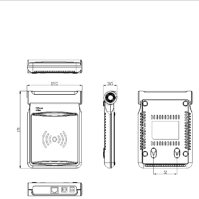
3.1 Dimensions
Figure 3-1 XC-RF812
XC-RF812 reader dimensions:
●Metric 170.0mm x122.5mm x 30.5mm(Not inclusive of accessories)
●Imperial 6.69in x4.82 in x 1.20 in
3.2 Weight
XC-RF812 reader weight:
●Metric Approximately 0.5kg (Not inclusive of accessories)
●Imperial Approximately 1.10 lb
User’s Manual
XC-RF812 Reader 5
4 Structural Features and Working Principals
4 Structural Features and Working Principals
4.1 Overall structure and working principals
The XC-RF812 reader comprises antenna modules, RF modules, baseband unit,
power supply unit and chassis components.
An RFID application environment consists of the XC-RF812 reader, tag, and PC
machine (PC). The baseband unit controlled by PC machine sends commands to
the RF unit. The RF unit sends the responding command according to tag types.
The tags receives command and returns responding messages which will be
amplied and modulated by the reception circuit and sent to the decoding unit of
baseband unit. The decoded data is sent to PC via communication interface on
the baseband unit.
The baseband unit performs tag data decoding and communication with the PC.
4.2 Bottom panel description
This section details the interfaces of the device and the LED indicators’ features.
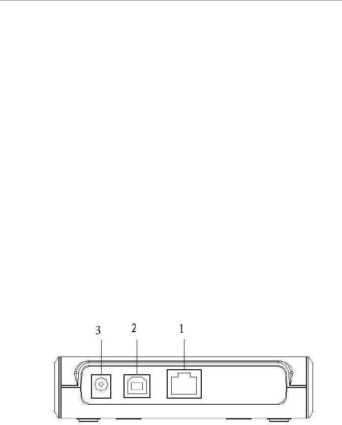
4.2.1 Panel
Figure 4-1 XC-RF812 Panel
Interface description is as follows:
1 - Ethernet interface
2 - USB interface (virtual serial interface)
User’s Manual
XC-RF812 Reader 6
4 Structural Features and Working Principals
3 - Power supply connector
(1) network interface, RJ45 network interface socket, 10M/100M adaptive
communication rate.
(2) ladder-USB interface
(3) DC power jack, φ 5 pin DC power socket, use output 5V/4A power adapter
power supply.
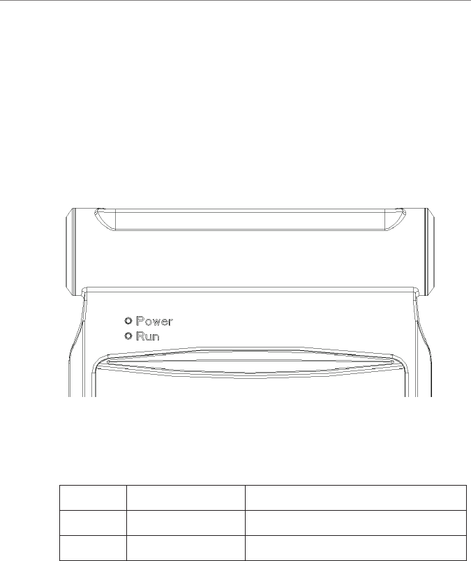
4.2.2 LED panel
Figure 4-2 XC-RF812 LED panel
For the LEDs’ denitions, see Table 4-1 :
Table 4-1 LED denitions
Number Name Denitions
POWER Power/LED After applying power to XC-RF812,
this LED turns green.
RUN System running LED Flashing green LED indicates that the system
is running.

User’s Manual
XC-RF812 Reader 7
4 Structural Features and Working Principals
4.3 PC and API requirements
This section describes the requirements of PC hardware and APIs.
4.3.1 PC
The minimum hardware conguration requirements for a host computer:
●CPU: Pentium 4, frequency: 1.7GHz or higher
●Memory: 512M Byte
●Hard drive: 20G
●RS-232 interface or 10M/100M network interface
Host computer operating system requirements:
Windows 2000 Service Pack 3; Windows Server 2003; Windows XP Service
Pack 2;Windows 7 ;Windows 8
4.3.2 API
●.NET API, VC, and JAVA dynamic link library
●RFID Reader Demo
For more information, see Programmer’s Reference Manual and RFID
Reader Demo User’s Guide
User’s Manual
XC-RF812 Reader 8
5 Installation and Troubleshooting
5 Installation and Troubleshooting
Please read and understand this chapter before installing the XC-RF812.
5.1 Installation tips
In order to ensure your personal and property, the following preparations are
required before installing XC-RF812.
This product uses DC + 5V / 4A DC power supply. Carefully check
voltage range before installing the XC-RF812!
The installation location should be free from rain, moisture and sunlight,
and is well ventilated.
Check the USB cable or network cable connection is good.
Any radio transmission equipment, including the XC-RF812, may cause
disturbance to the performance of medical devices that have no proper
protection. Please consult the manufacturers of relevant medical devices
to avoid such event. This equipment may also cause disturbance to other
electronic equipment while it is in operation.
5.2 Installation conditions
Before installing the XC-RF812 reader, please carefully check the product is in
good condition, and the accessories are complete. Please check the product and
its accessories according to the packing list. Please contact us immediately if
there is any discrepancy or damage.
In addition, check whether the installation meets the following conditions:
●Complying with workplace standards;
●The accessories are complete and meet required standards.
5.2.1 Connecting the XC-RF812
Connect the reader to the PC.
Connect the XC-RF812 reader to the PC with a network cable or a USB cable.
The PC IP address and reader IP address must be in one network segment (default

User’s Manual
XC-RF812 Reader 9
5 Installation and Troubleshooting
192.168.0.210) to create network connection. Check the USB driver is installed
to use USB connectivity.
5.2.2 Apply power to the XC-RF812
Apply power to the XC-RF812 reader by following steps:
●Check that the AC input voltage and operating frequency to meet the
requirements: AC 100-240V input, 50-60Hz;
●Check the adapter output voltage is 5V / 2A;
●Check the power supply connection are correct and secure;
●After applying power to the reader, wait about 10 seconds. The power /
work LED will is ashing, and the reader will play two sounds. The reader
will enter initialization state, and the system enters standby mode when
initialization process is completed.
After booting the system, the XC-RF812 reader, by default, is in
standby mode. The reader does not transmit power in the initialization
and standby mode (RF power amplier is turned off), and only operates
after receiving “read tag” command from the PC or “open amplier”
command.
5.3 Troubleshooting
This section describes troubleshooting common problems, in particular, the
general problems occur when the installation is not correct, and explains how to
correct it.
Troubleshooting common issues:
●Reader does not respond
○ Power indicator LED is on → check the relevant cable connections, and
check the corresponding items in accordance with the state of the relevant
LED indicators;
○ Network communication status → check the connection IP is correct;
check if there is an IP address conict;
●Read / write tag error
○ Check the reader type on application software is congured correctly;
○Check if reader and tag is compatible;
○ Check tag placement, and if tag is present is reader eld;

User’s Manual
XC-RF812 Reader 10
5 Installation and Troubleshooting
○Check if there exists electromagnetic interference;
○Check tag access password is required, and if the password is correct;
○Check if tag is damaged.
5.4 Acceptance
Acceptance criteria are given mainly from two aspects: structure and properties.
5.4.1 Structure acceptance
Check if the installation meets installation standards, and if the equipment
connection is secure.
● Check if the reader is rmly xed.
●Check if the screws are tightened.
For additional information see Installation Notes!
5.4.2 Performance Acceptance
Check if the reader operates properly mainly from the following two aspects:
●check if the reader is working properly.
●check if the read range meets the requirements.
User’s Manual
XC-RF812 Reader 11
6 Operating RFID Demo
6 Operating RFID Demo
6.1 Preparation before operating RFID Demo
User can use Demo software to operate the XC-RF812 reader, including system
control, parameter setting, parameter query, communication mode selection,
and read and write RF tag operation. One CD-ROM which comes with
shipment provides .NET Demo, .NET APIs, and C ++ APIs for users’ secondary
development.
6.2 Demo software application environment
●Software
Windows 2000 Service Pack 3; Windows Server 2003; Windows XP Service
Pack 2; Windows 7; VISTA system
●Hardware
Minimum P4 / 1.7GHz PC CPU, 512M or above memory, and 20G hard drive
6.3 Installing RFID Demo
●RFID Demo V1.2 or higher version
Note: The Windows version RFID Demo is described in this section.
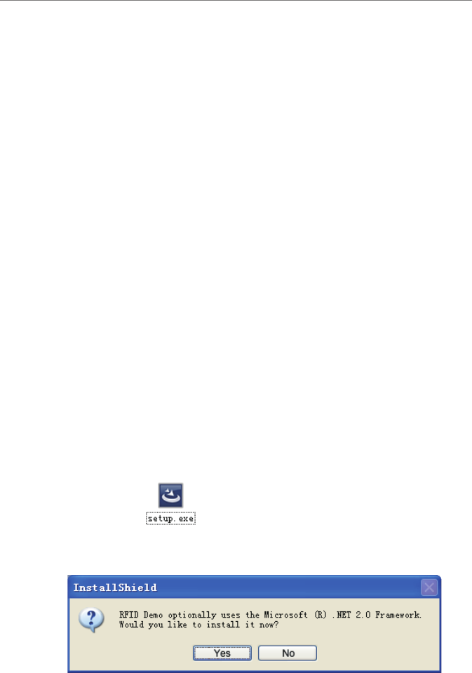
Double-click on .
If .NET Framework 2.0 is not installed, the program will automatically prompt
installation, as shown below:
Figure 6-2
User’s Manual
XC-RF812 Reader 12
6 Operating RFID Demo
Select “Yes” to install .NET Framework 2.0:
Figure 6-3
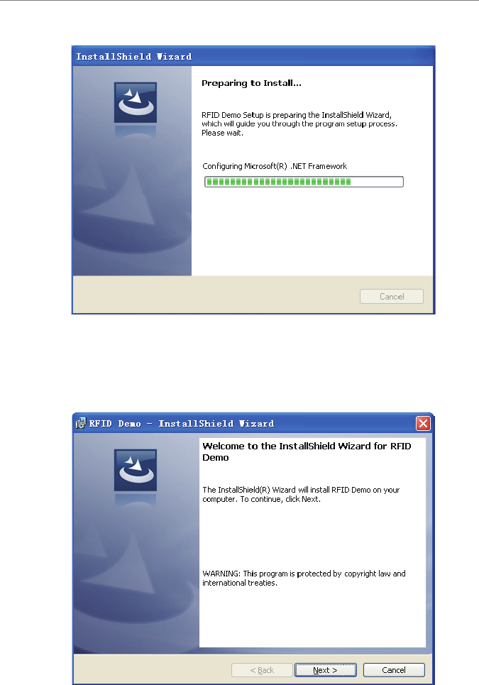
When the .NET Framework 2.0 installation is complete, the program enters
“Ready to Install” phase (if.NET Framework 2.0 is installed, the program
directly enters this phase). It takes a few seconds to nish, and then enters the
“Installationshield Wizard” screen, as shown below:
Figure 6-4
User’s Manual
XC-RF812 Reader 13
6 Operating RFID Demo
Click “Next”:
Figure 6-5
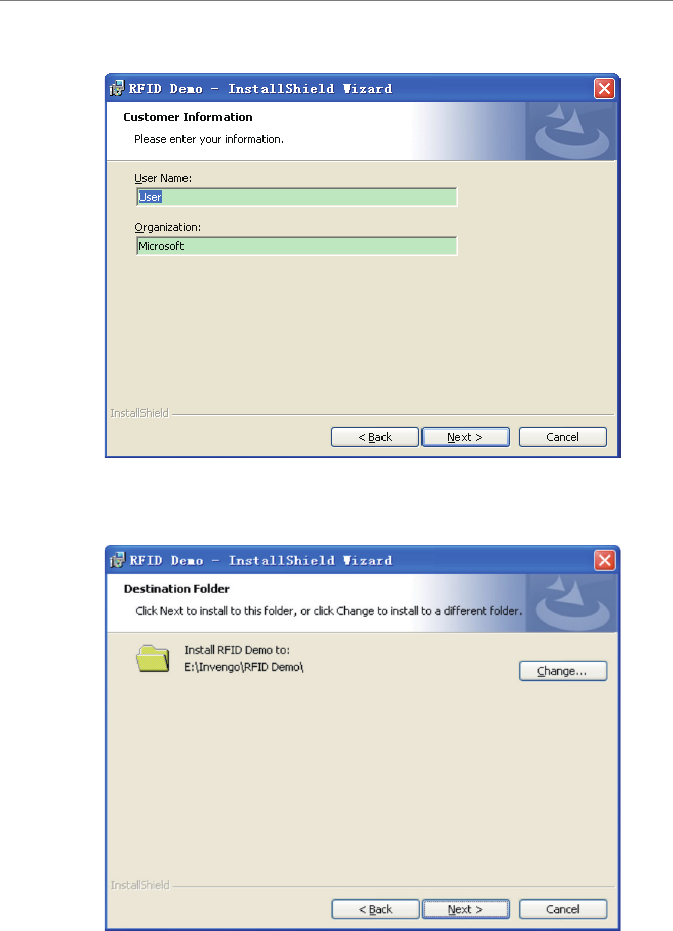
Enter user name and organization, and click on “Next”:
Figure 6-6
User’s Manual
XC-RF812 Reader 14
6 Operating RFID Demo
The default installation directory is: “E: \ Invengo \ RFID Demo \”. If required,
click on the button “Change” to select a directory, and then click “Next”:
Figure 6-7
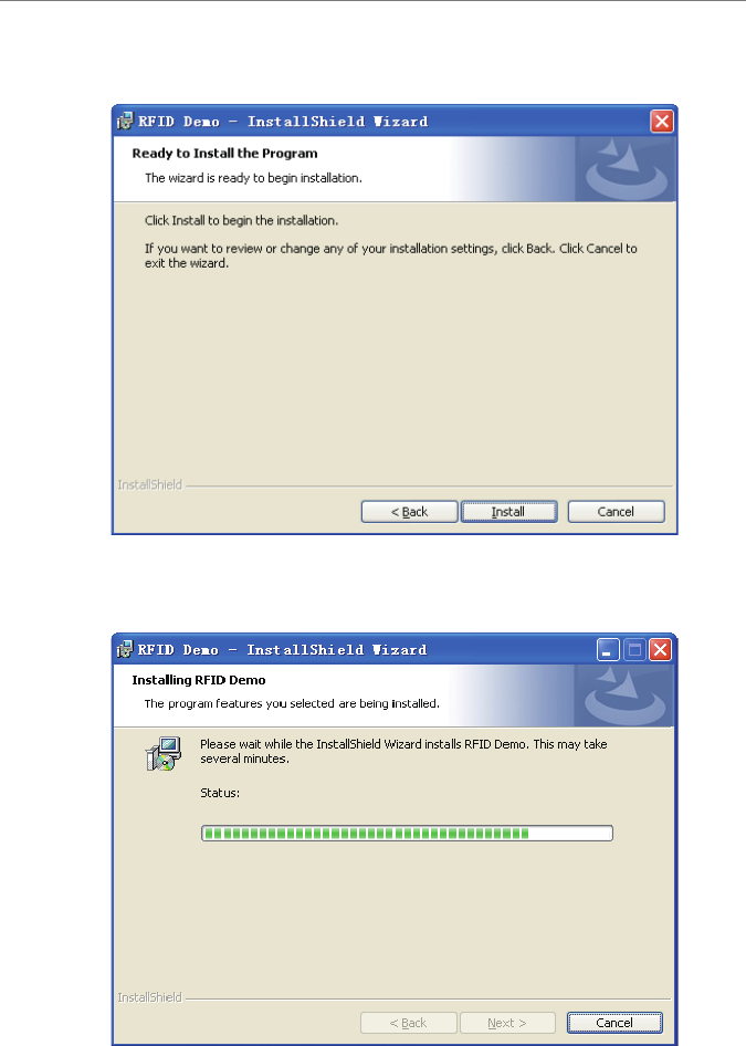
Click “Install”:
Figure 6-8
User’s Manual
XC-RF812 Reader 15
6 Operating RFID Demo
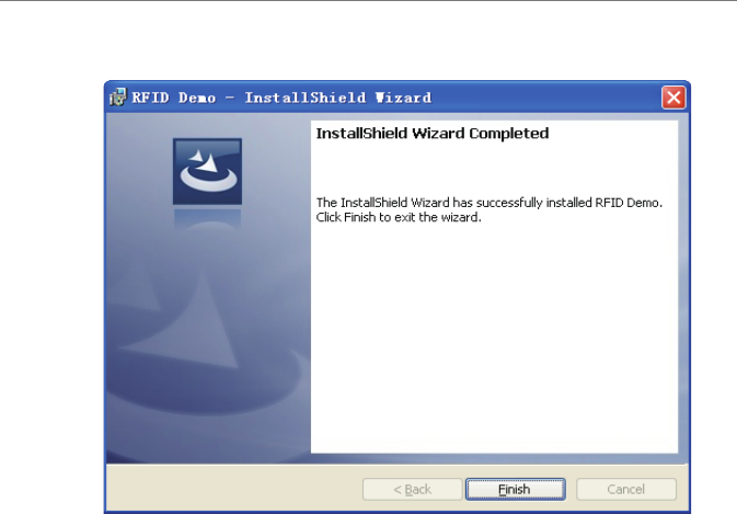
After being installed, the screen appears as follows:
Figure 6-9
Click “Finish” to Complete software installation, and a desktop shortcut of “RFID
Demo” appears.
6.4 Demo Software Operation
6.4.1 Start screen
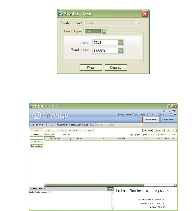
1. Start the software, and you can establish a network port or a USB connection. If
the equipment’s IP address is uncertain, you can use the device’s USB interface
to establish a connection. Before using USB communication, you need to install
the corresponding driver “linux-cdc-acm.inf”. After the installation is complete,
you can navigate “My Computer -> Properties -> Hardware -> Device Manager
-> Ports “ to view the virtual serial ports, and select the corresponding serial port
connection as shown in Figure below:
User’s Manual
XC-RF812 Reader 16
6 Operating RFID Demo
Figure 6-10
2. The default entry is “Demo mode when the network or serial port connection is
established. The screen appears as below:
Figure 6-11
The main interface is divided into upper, middle, and lower sections.
(1) Upper section: it displays software name, and company Logo, and includes
two buttons used to switch between Demo mode and Issue mode.
(2) Central section: reader conguration is on the left of Central section;
operation result is shown on the right Central section.
(3) Lower section: the left part shows running messages, for example, whether
the reader is connected successfully; the right part shows statistics and
displays the current read operation status.
User’s Manual
XC-RF812 Reader 17
6 Operating RFID Demo
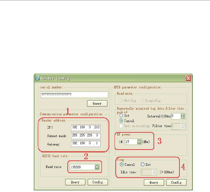
6.4.2 Reader Conguration
On the “Reader Cong” screen, user can set reader conguration parameters,
such as communication parameters (reader address, and baud rate), RFID
parameters (RF port power adjustment), and intelligent sleep mode, and perform
some basic tests.
The reader must be properly connected before you begin to congure the reader.
Click on the “Reader Cong”, and screen appears.
Figure 6-12
1, Reader address setting, and query
First, connect the reader to the host computer via USB connection, and click
the pop-up “reader conguration” dialog box on “Reader Cong”, as shown in
“1” of Figure 6-12”. Input reader IP information, including IP address, subnet
mask, and gateway. Click on the “Cong”. Click on the “Query” to get network
information.
2, Serial port baud rate setting, and query
As shown in “2” of Figure 6-12”, click on the drop-down box to select the
required parameter of “baud rate (115200bps, 19200bps, and 9600bps)”, and
then click on the “Cong”. Click on the “Query” to get baud rate (information.
3, RF port power settings, and query
As shown in “3” of Figure 6-12”, click on the drop-down box to select the
User’s Manual
XC-RF812 Reader 18
6 Operating RFID Demo
required parameter of “Power adjustment” (9 to 30dbm), and then click on the
“Cong”. Click on the “Query” to get power adjustment information.
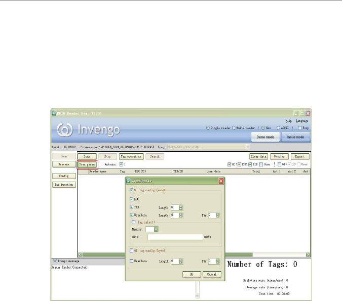
6.4.3 Scan conguration
Scan conguration setting mainly includes read mode. Click the “Scan param”
in Figure 6-13. The “Scan Cong” dialog box appears.
Figure 6-13
1, 6C tag read conguration (double-byte)
EPC: Check the EPC to read the adaptive length of EPC number.
TID: Check the TID, and you can set the length of data to read.
UserData: Check the UserData, and you can set the length of data to be read
2, Tag lter
Check tag lter. In the drop-down box, select the EPC or TID. Fill in the data
of which the tag to be ltered. And the tag with specied data content can be
acquired in the next read operation.
3, 6B tag conguration
UserData: check UserData, you can set the length of the parameter to be read
and the starting address.
User’s Manual
XC-RF812 Reader 19
6 Operating RFID Demo
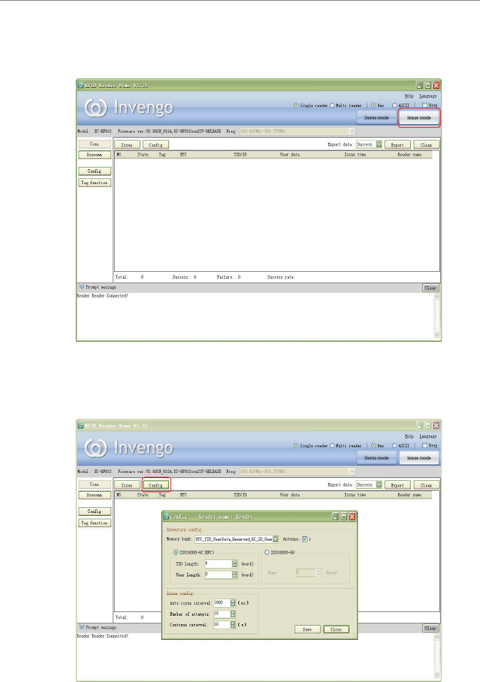
6.4.4 Issue mode conguration
1, Click “Issue mode” on the main screen, as shown in Figure 6-14.
Figure 6-14
2, Enter issue mode screen, and click the “Cong” button, a pop-up conguration
dialog box appears as shown in Figure 6-15.
Figure 6-15
User’s Manual
XC-RF812 Reader 20
“Cong” screen is described as follows:
●Scan memory bank: Set the memory bank to be read
●Antenna: Select the corresponding antenna
●TID length (6C): Set the TID length
●User length (6C): Set the length of user memory bank of 6C tags
●User length (6B): Set the length of the user memory bank of 6B tags
●Automatically issuing interval: interval time for issue operation
●Attempts of issue operation: set the number of attempts to performs issue
operation after a failed issue operation
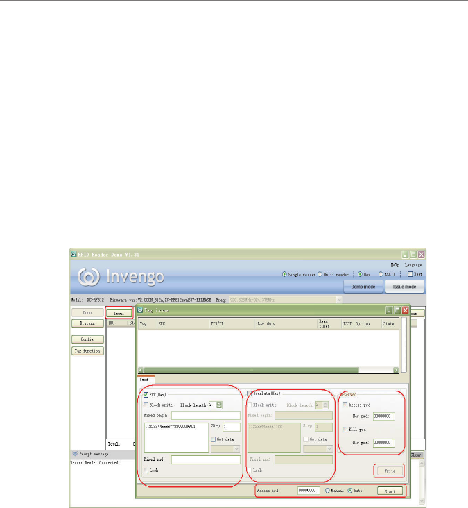
3, Once congured, click on the "Issue" button, and a pop-up dialog box appears
as shown in Figure 6-16.
Figure 6-16
The Issue screen includes “General” and “Advanced (6C)” modes. The “General”
mode includes “EPC, UserData and reserved block”.
●EPC
Block write, and block length: Set block write for specic tags, and set block
length.
Fixed beginning: Set the initial xed data to be written.
6 Operating RFID Demo

User’s Manual
XC-RF812 Reader 21
Step: Set interval time of write data .
Fixed ending: Set a xed data to be written on a tag memory bank.
Locking: Encrypt written data operation.
Get Data: Get the written tag data source.
●UserData:
Block write, and block length: Set block write on specic tags, and set block
length.
Fixed beginning: Set the initial xed data to be written.
Step: Set interval time of write data operation.
Fixed ending: Set a xed data to be written on a tag memory bank.
Locking: Encrypt the written data.
Get Data: Get the written tag data source.
●Reserved block:
Set Access Password: Password is required to access tag memory.
Set Kill Password: Password is required for kill tag operation.
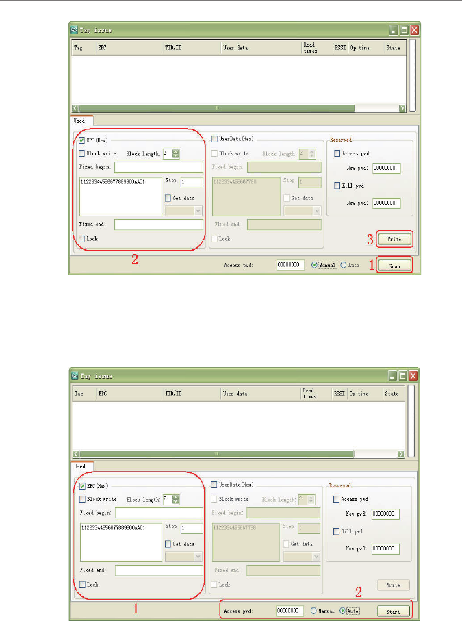
6.4.5 Issue tag operation
When issue mode conguration as shown in Figure 6.4.4 is complete, user can
perform issue operations which include “General” and “Advance” modes. Two
issue modes including “manual” and “automatic” are described as follows:
● Manual: 1 - Click "Scan" -> "Stop Scan" -> 2 – write data on EPC memory
block -> 3 – Click “Write"
6 Operating RFID Demo
User’s Manual
XC-RF812 Reader 22
Figure 6-17
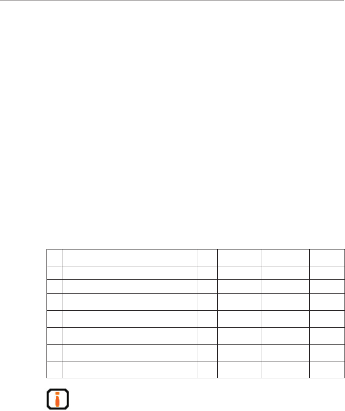
● Automatic: Select “Auto” -> 1 – write data on EPC memory block -> 2
– Click “Start”, and then put the tags on the reader eld to perform write
operation.
Figure 6-18
6 Operating RFID Demo

User’s Manual
XC-RF812 Reader 23
7 Routine Maintenance, FAQs and Troubleshooting
7.1 Routine maintenance
See 8.2 Storage Requirement
7.2 FAQs and troubleshooting
This section introduces solutions to some of the common problems or
irregularities during the usage of the device.
●The “Power” indicator does not light up after the power supply has been
switched on
○Check if the power supply from the power adapter is working normally,
check also if the AC power voltage falls between 100V and 240V
●USB port can not be connected
○check if the virtual serial port driver is installed
○check if a virtual serial port chosen is correct.
○check if reader serial port baud rate is 115200bps.
●Unable to connect through Ethernet port
○The default IP address of the reader under factory setting is: 192.168.0.210.
If the host PC’s IP address is in the same network segment which the
reader’s IP address is in, for example “192.168.0.XXX”, the connection
will be successful. If the user forgot about the reader’s IP address, user can
recongure the IP address of the reader that is connected to the host PC
through USB serial port.
●Unable to read tag
○Check if the serial cable or the network cable is properly connected. Any
disconnection or insecure connection will cause the command from the PC
not being transferred to the reader.
○Please check if both ends of the RF connector has been tightened. Check
also if the tag is damaged. If problem persists, you may need to call the
Invengo service line for help.
7 Routine Maintenance, FAQs and Troubleshooting

User’s Manual
XC-RF812 Reader 24
8 Transport and storage
8.1 Transport Requirement
All Invengo Quality Checked equipments shall meet the standards specied for
road, rail, sea and other transport requirements. The transport process requires
attention to ensure that equipment will not be subject to violent collisions and
excessive vibration, rain, erosion, chemical corrosion and harmful gases.
8.2 Storage Requirement
The long term warehouse storage environment for the XC-RF812 reader must
fulll the following conditions:
●Ambient temperature:-20oC to +60oC;
●Relative temperature:5% to 95%RH;
●No sudden temperature and humidity changes, ambient air is not harmful or
composed of acidic and other corrosive gases
8 Transport and storage
User’s Manual
XC-RF812 Reader 25
9 Packaging and Un-packing
9.1 Packaging
The XC-RF812 reader is packaged using cassette packaging and can be
transported through large transport container.
9.2 Un-packing
In order to facilitate future storage and transport, keep the box and packaging
materials.
Apart from the XC-RF812 reader, the package also contains the following
accessories, as shown in the table below:
Table 9-1 Accessories checklist
No. Item Unit Order Code Remark No.
1Output 5V / 4A power adapter 1 Piece 1080200010 Standard
2Three core 10A-250V-1.8m power cord 1 Piece 2200500026 Standard
3RJ45 crossover cable -1.5m 1 Piece 2200300003 Standard
4USB cable 1 Piece 2200300049 Standard
5CD-ROM 1 Piece Standard
6Warranty Card 1 Sheet Standard
7Product certication 1 Sheet Standard
Please check the product and its accessories carefully according to the
packing list. Please contact us immediately if there is any discrepancy or
damage.
9 Packaging and Un-packing

User’s Manual
XC-RF812 Reader 26
10 After-sale Service and Contact
10.1 After-sale service
When a user encounters unsolvable problems during the device usage, please
contact our customer service center.
Before the user contacts the customer service center, please prepare the following
information:
10.1.1 Reader information
●reader models;
●reader serial number (on the rear panel of the reader);
●any changes made to the reader or the tag;
●installation of reader;
●reader application software;
10.1.2 Computer Information
●computer brand and model;
●computer's processing speed and available memory;
●serial port used;
●computer operating system;
10.2 Other matters
If our customer service staff has conrmed with the user to return his/her
reader for maintenance, our representative will present the user with a return
merchandise authorization (RMA). Please indicate the RMA no. on the exterior
of the return product packaging, provide the same no. on a piece of paper and
place it in the packaging. This will ensure the quick processing of the return
product.
10 After-sale Service and Contact

User’s Manual
XC-RF812 Reader 27
Please follow these steps when returning the reader for maintenance:
●Carefully pack the reader and its accessories into the original antistatic foam
box. If the box no longer exists, please use a box with protective effect;
● Use ller to cover up the products in the box;
●Place a note written with RMA no. into the box;
●Indicate RMA no. and the word “fragile” on the exterior of the box.
This device complies with Part 15 of the FCC Rules. Operation is subject to the
following two conditions: (1) this device may not cause harmful interference,
and (2) this device must accept any interference received, including interference
that may cause undesired operation.
Changes or modications not expressly approved by the party responsible for
compliance could void the user's authority to operate the equipment.
NOTE: This equipment has been tested and found to comply with the limits
for a Class B digital device, pursuant to Part 15 of the FCC Rules. These limits
are designed to provide reasonable protection against harmful interference
in a residential installation. This equipment generates, uses and can radiate
radio frequency energy and, if not installed and used in accordance with the
instructions, may cause harmful interference to radio communications. However,
there is no guarantee that interference will not occur in a particular installation. If
this equipment does cause harmful interference to radio or television reception,
which can be determined by turning the equipment off and on, the user is
encouraged to try to correct the interference by one or more of the following
measures:
-- Reorient or relocate the receiving antenna.
-- Increase the separation between the equipment and receiver.
-- Connect the equipment into an outlet on a circuit different from that to which
the receiver is connected.
-- Consult the dealer or an experienced radio/TV technician for help.
RF Exposure Statement
To maintain compliance with FCC’s RF Exposure guidelines, this
equipment should be installed and operated with minimum distance
between 20cm the radiator your body: Use only the supplied antenna.
10 After-sale Service and Contact

Shenzhen HQ:
Corporate Headquarters
Invengo Information Technology Co., Ltd.
3/F, No.T2-B, High-tech Industrial Park South,
Shenzhen 518057, China
Tel: +86 800 830 7036
Fax: +86 755 2671 1693
Email: sales@invengo.cn
Website: www.invengo.cn
Singapore:
Invengo Technology Pte. Ltd.
10 Kallang Avenue, # 05-15 Aperia tower 2,
Singapore, 339510
Tel:+65 6702 3909
Email: invengo.sales@invengo.sg
Website: www.invengo.sg
US:
Invengo Technology Corp
2700-160 Sumner Blvd.
Raleigh, NC 27616, USA
Tel: +1 919 890 0202
Toll Free: +1 855 379 2725
Email: sales@invengo.com
Website: www.invengo.com
Europe:
Invengo Technology BV
Belder 30-A, 4704RK Roosendaal,
The Netherlands
Tel: +31 88 6363 793
Fax: +31 88 6363 794
Email: web@invengo.eu
Korea:
Invengo International Pte. Ltd (Korea)
30F ASEM Tower, 517 Yeongdong-daero,
Gangnam-gu, Seoul 135-798 Korea
Tel: +82 2 6001 3525
Fax: +82 2 6001 3003
Email: justin.kou@invengo.sg