Invengo Information Technology XC2900-F6C Handheld RFID Reader with WiFi transmitter User Manual XCRF 500
Invengo Information Technology Co., Ltd. Handheld RFID Reader with WiFi transmitter XCRF 500
UserManual.wiki
>
Invengo Information Technology
>
XC2900 F6C User Manual
User Manual
Navigation menu
Upload a User Manual
Namespaces
Wiki Guide
HTML
PDF
Info
Views
User Manual
Discussion / Help
Navigation


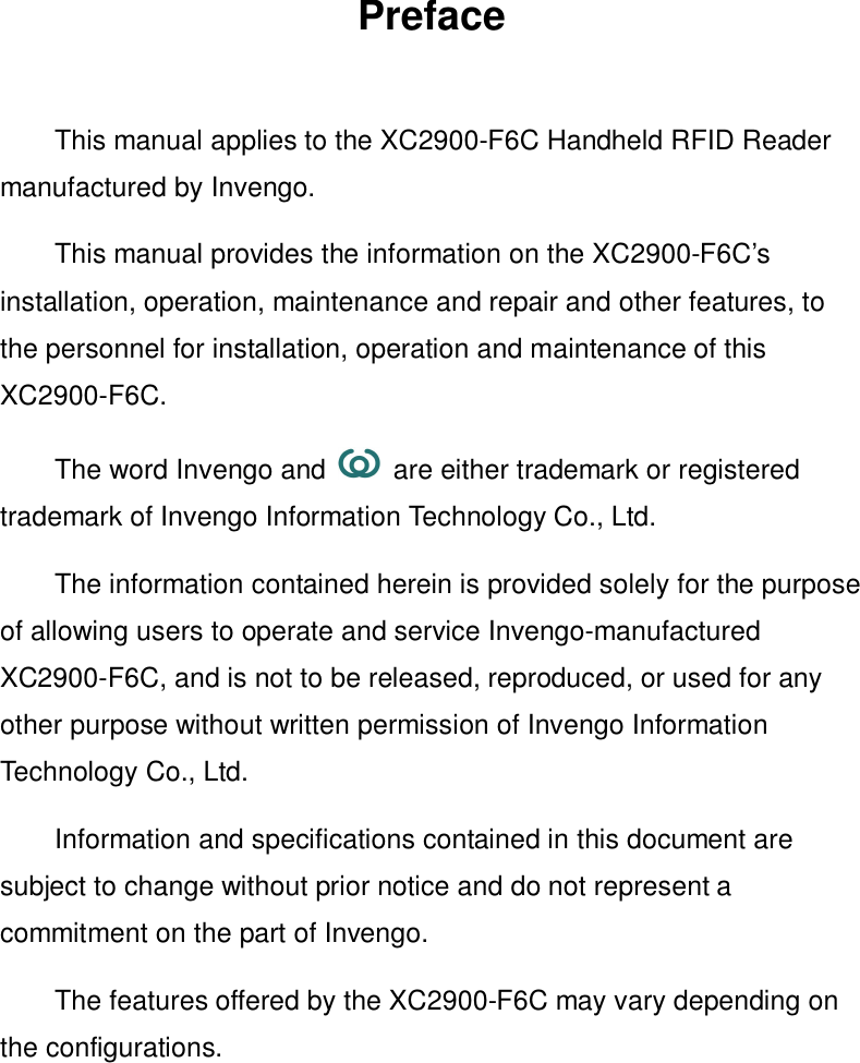

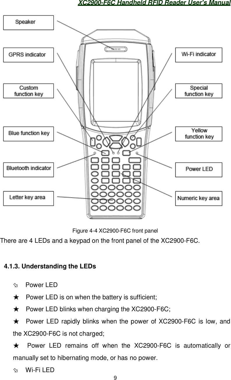
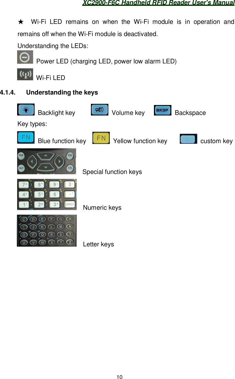
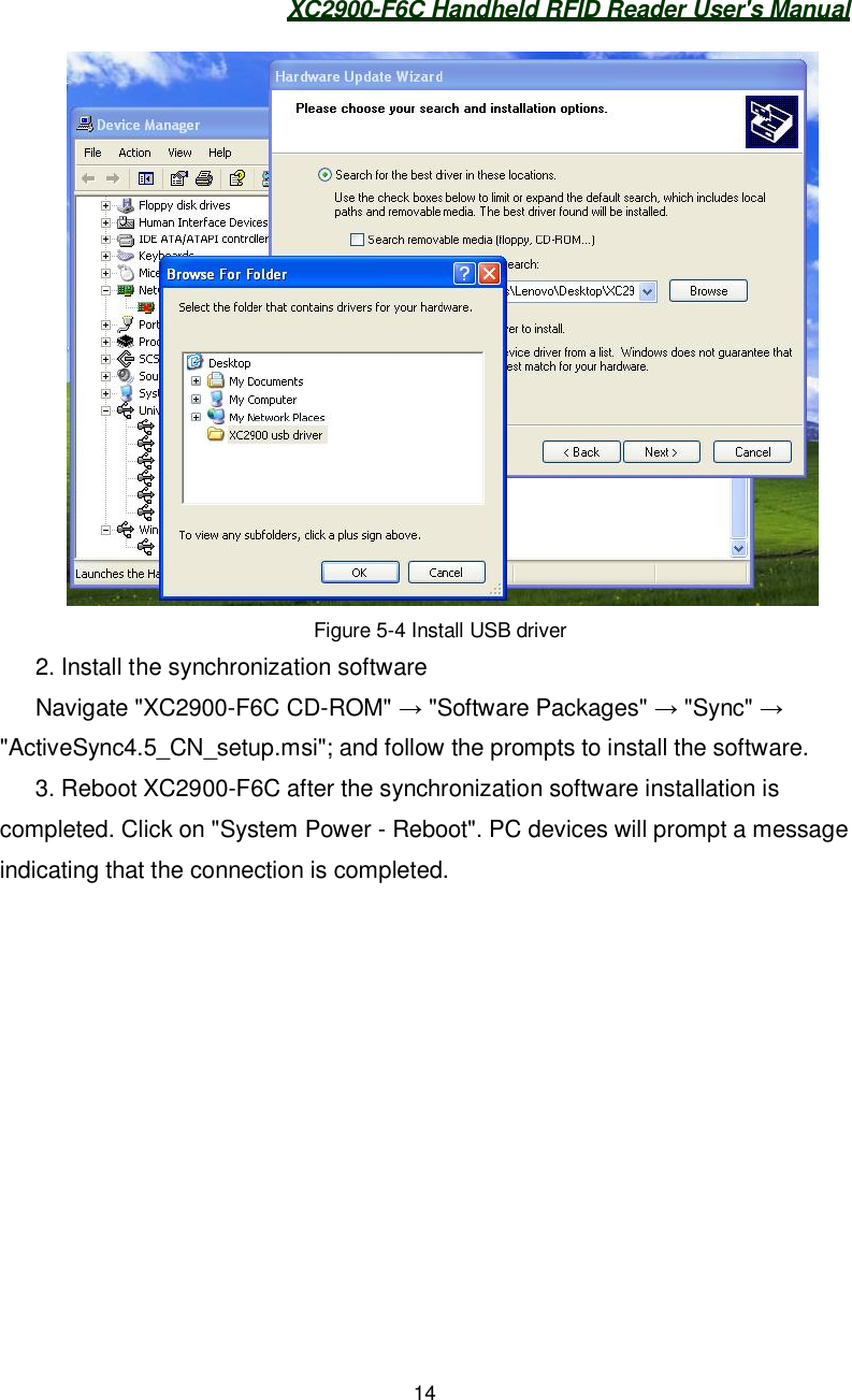
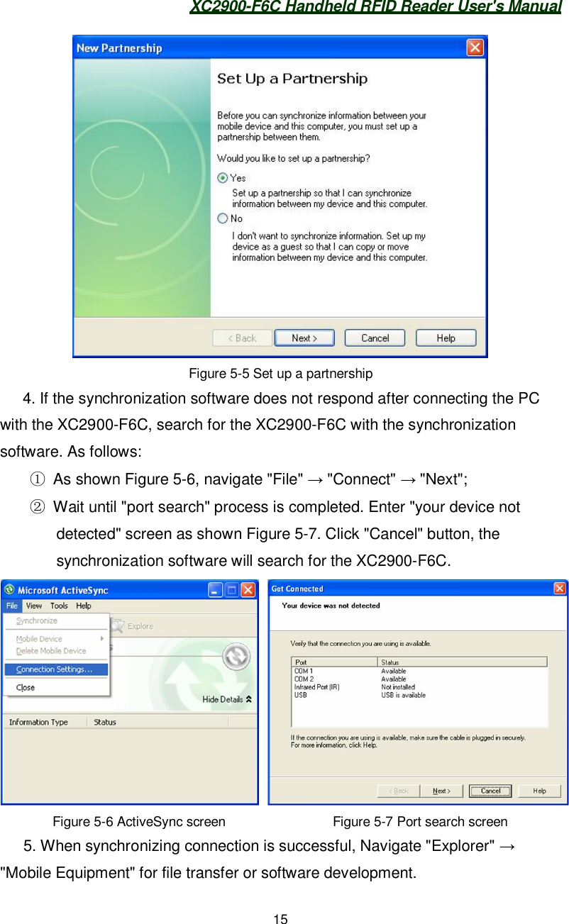
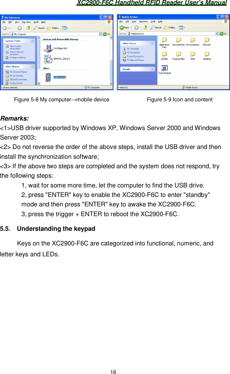
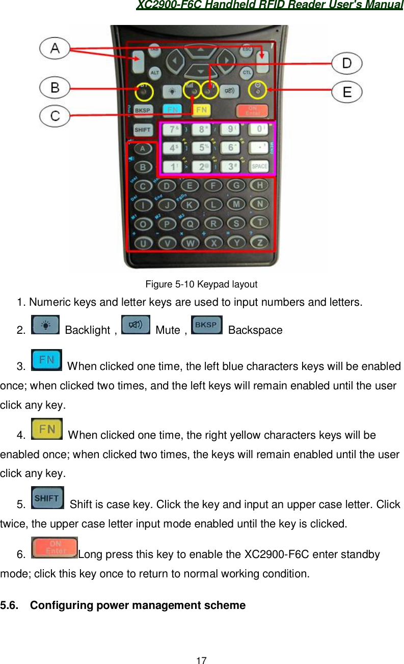
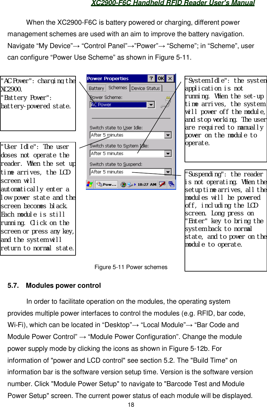
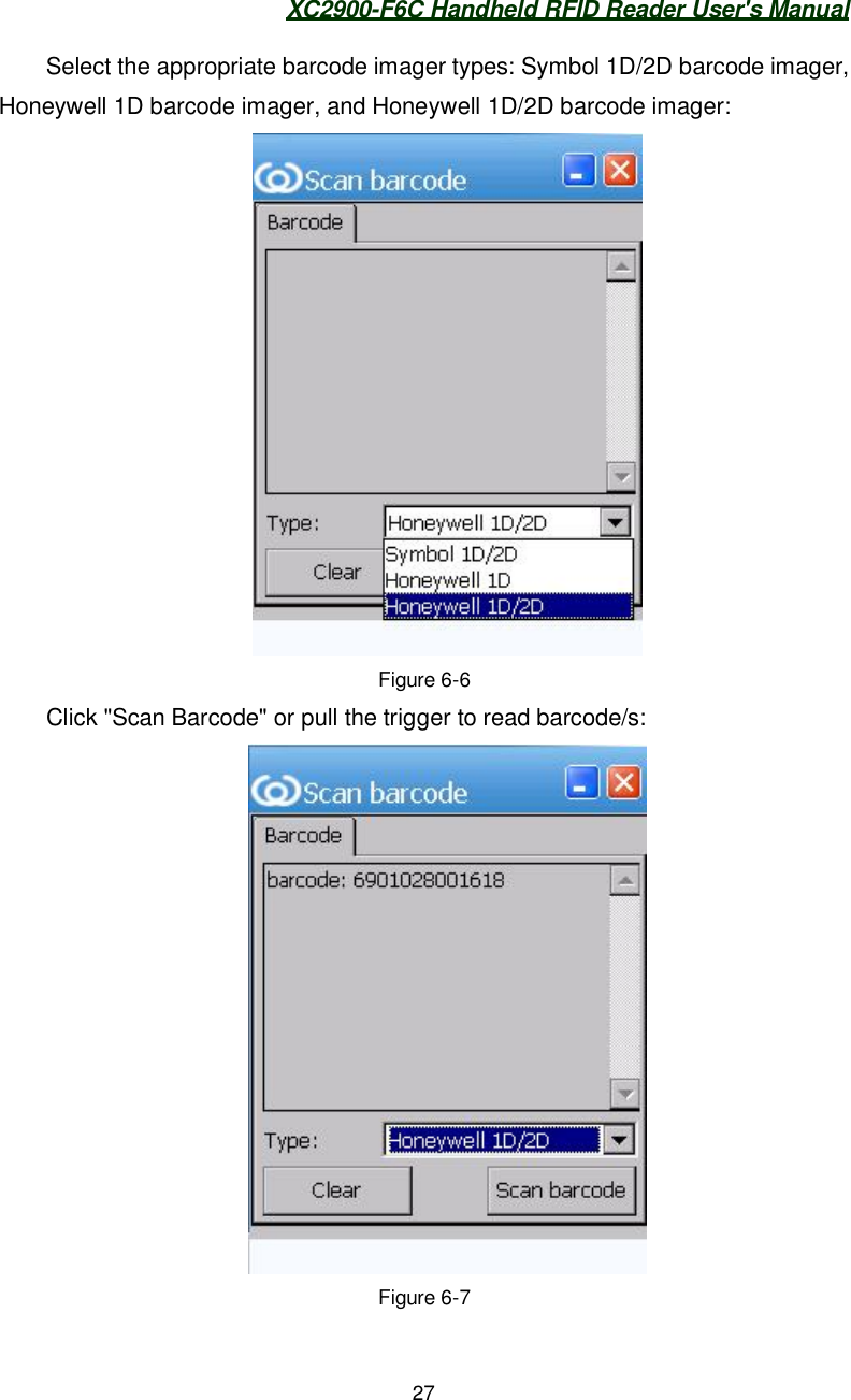
![XC2900-F6C Handheld RFID Reader User's Manual115. Configuring the XC2900-F6C5.1. Screen CalibrationTo calibrate the screen, navigate “My device” “Control Panel”“Stylus” “Calibrate”. Click “Recalibrate” and save configuration as shown inFigure 5-1:Figure 5-1 Control panel Stylus5.2. Query battery power Info & backlight control[Battery capacity, Charge status query] To query the current overall power,click "Power Update" on the screen.When the battery status bar shows:"No battery" indicates the XC2900-F6C is powered with a charger;"Battery" indicates the XC2900-F6C is battery-powered; "The battery is charging."indicates the battery is charging. "Battery charging completed." indicates that thebattery is fully charged. It appears in Figure 5-2.](https://usermanual.wiki/Invengo-Information-Technology/XC2900-F6C/User-Guide-1621449-Page-19.png)
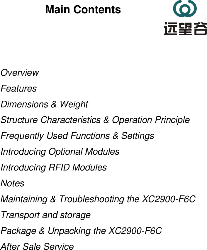
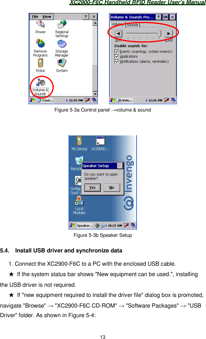
![XC2900-F6C Handheld RFID Reader User's Manual12Figure 5-2 Control panel Power and LCD control[Backlight Control] Navigate "Desktop" "Local Modules" " Power andLCD Control". Move slide bar icon or click the buttons on both sides to adjust thebrightness of the LCD. User can also press to adjust the backlightbrightness.5.3. Volume & soundNavigate "My Device" "Control Panel" "Volume & Sound". Move theslide bar icon or click the buttons on both sides to adjust the speaker volume asshown in Figure 5-3a.To turn the XC2900-F6C to "mute" state, press . To cancel “mute”state, press and "Speaker Setup" dialog box appears as shown in Figure5-3b. Select "Yes" button to turn on the speaker, and select "No" to turn off thespeaker.](https://usermanual.wiki/Invengo-Information-Technology/XC2900-F6C/User-Guide-1621449-Page-20.png)
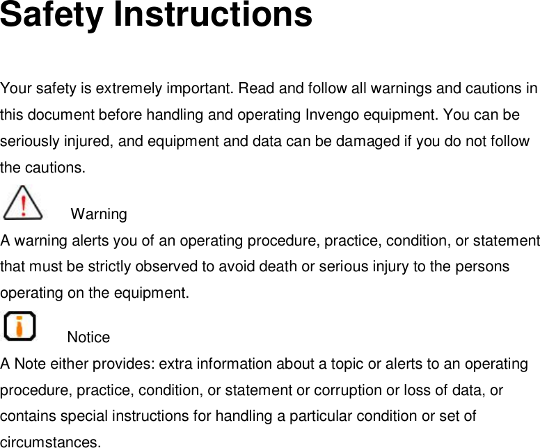
![XC2900-F6C Handheld RFID Reader User's Manual205.8. Set auto startAfter cold booting or removing the battery, the XC2900-F6C will restore thefactory configuration, and the user settings will not be saved. To facilitate theoperation, the XC2900-F6C offers the auto-start function, which enables the autostart of the desired configuration programs. Configure as follows:Create a text file called "startup.txt" , and then copy to [my device] [InvengoFlash] directory with the PC synchronization software, ActiveSync. Writefollowing data on the “startup.txt”:1. Users can set up the auto launch program of Windows directory afterbooting the system, as follows: Open the “startup.txt”, Enter [program fullname.Extension name]. For example, just type [locMods.exe] in the file to startthe " locMods" program in the Windows directory when booting the XC2900-F6C.The program will be automatically started when booting the XC2900-F6C.2 Users can set up the launch of the program in [InvengoFlash], as follows:Open the “startup.txt”, enter [the process name. Extension name]. For example,just type [locMods.exe] in the file to start the " locMods" program in the“InvengoFlash” when booting the XC2900-F6C.The program will be automatically started when booting the XC2900-F6C.5.9. Set “quick launch program”When the XC2900-F6C is “cold-booted” or the battery is removed, theXC2900-F6C will restore the default configuration. The XC2900-F6C features“Quick Launch Program” function. Double-click the icon “Configurable QuickLaunch” to configure the programs as follows:Navigate “My Device” and create or save a file named “Launch.txt” in thedirectory of “InvengoFlash” with ActiveSync.](https://usermanual.wiki/Invengo-Information-Technology/XC2900-F6C/User-Guide-1621449-Page-28.png)
![XC2900-F6C Handheld RFID Reader User's Manual211. User can set the “Quick Launch Programs” on “InvengoFlash” as follows: inputthe [program complete name.extension name] in the “launch.txt”, and click thedesktop icon/s. For example: input [demo.exe] in the “launch.txt”, and click thedesktop icon to run the “demo” program.2. The program/s installed in SD card can be set to be as “Quick LaunchProgram/s” as follows: open “launch.txt”, input [program completename.extension name]. For example: input [demo.exe] in the “launch.txt” and thedesktop icon will appear. Note: Input Only one program name in a separate line in the“launch.txt’.5.10. Power-down protectionTo save the settings before battery replacement, strictly operate as follows:When the battery power is low, Set the XC2900-F6C to standby mode, and thenreplace the battery (The XC2900-F6C in standby mode can maintain standbywithin 15 seconds after power-down) within 15 seconds. Rebooting theXC2900-F6C is not required when the battery replacement is completed within 15seconds. Press the Enter key to wake up system, and the system parametersconfiguration and user data remains unchanged. If the battery replacement takes more than 15 seconds, reboot theXC2900-F6C. (Press the trigger + Enter key to reset the 2900).](https://usermanual.wiki/Invengo-Information-Technology/XC2900-F6C/User-Guide-1621449-Page-29.png)
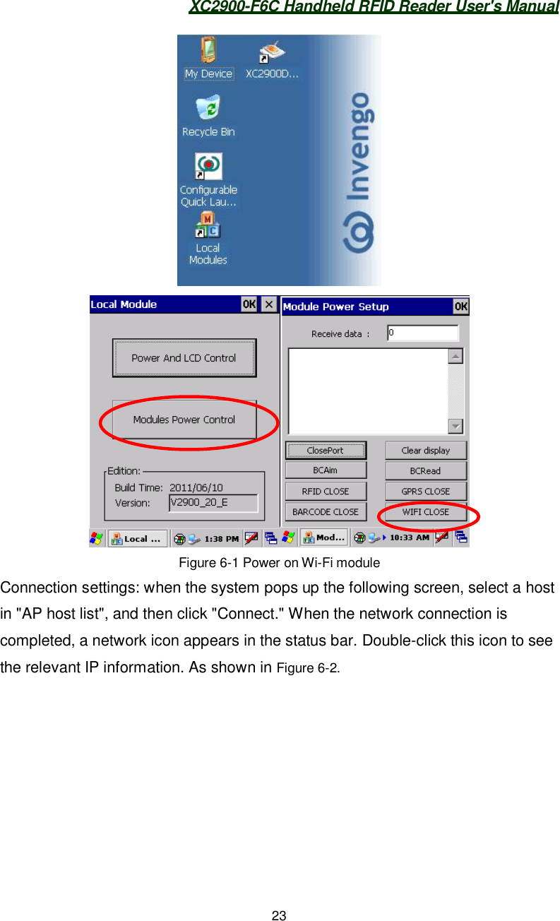
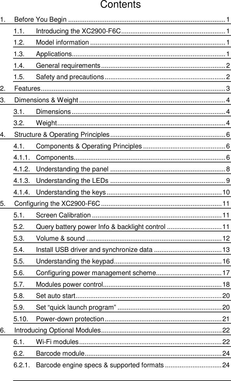
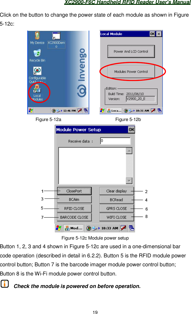
![XC2900-F6C Handheld RFID Reader User's Manual246-2:Figure 6-2 Wi-Fi module setting6.2. Barcode module6.2.1. Barcode engine specs & supported formatsTwo-dimensional bar code:Resolution: 752 X 480 pixelsScan Mode: Trigger mode and interrupt modeSupported symbologies:One- dimensional symbologies: Code 39, Code 128, Codabar, UPC, EAN,ITF25, RSS, Code 93, Code blockTwo- dimensional symbologies:: PDF 417, MicroPDF417, Maxi Code, Datamatrix, QR Code, Aztec, Aztec Mesa, Code 49, UCC Composite6.2.2. Read barcode with moduleClick on the desktop "Local Modules" icon as shown Figure 6-3. In thepop-up dialog box, click the "Module Power Control" button, as shown in Figure6-3b. A "Module Power Setup" dialog box appears as shown in Figure 6-3c. Clickthe "Barcode open" button once. Then click [BCRead] button once and click theAP host listConnect](https://usermanual.wiki/Invengo-Information-Technology/XC2900-F6C/User-Guide-1621449-Page-32.png)
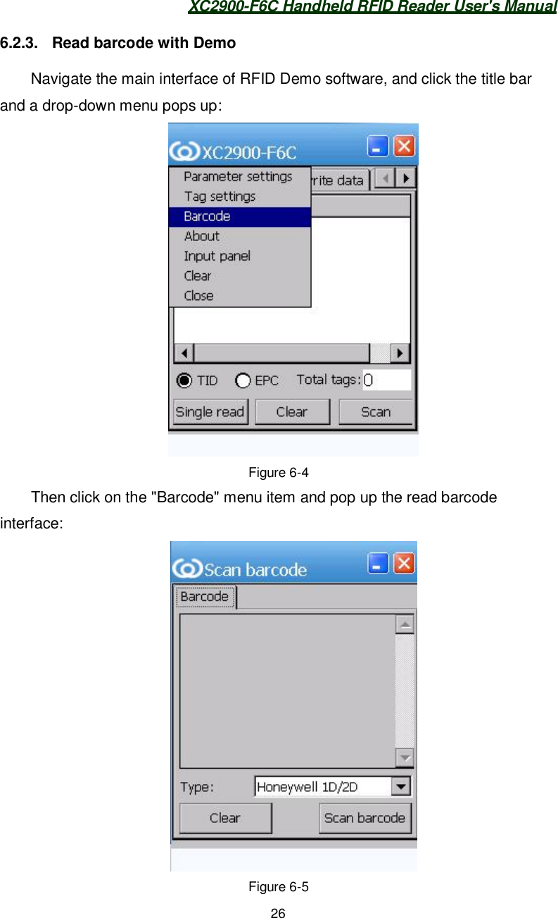
![XC2900-F6C Handheld RFID Reader User's Manual25[BCRead] button once to read a barcode supporting the one-dimensional barcode (IS4823) placed within the effective range. Barcode data appears in the“Data column”.Figure 6-3Understanding the buttons:Closeport button is used to close or open the barcode imagerClear Display button is used to empty the data in the boxBCAim button is used to open aiming light for the imager.Data column Barcode dataRead one-dimensionalbarcode](https://usermanual.wiki/Invengo-Information-Technology/XC2900-F6C/User-Guide-1621449-Page-33.png)
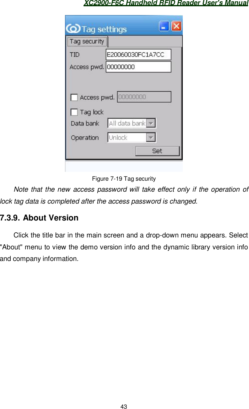
![XC2900-F6C Handheld RFID Reader User's Manual44Figure 7-20 About7.4. About APIsThe APIs are the middleware of the XC2900-F6C and the applicationsoftware, which provides the interfaces for secondary software development forthe system integrator or end-user.For more information view [CD-ROM] - [RFID module] - [RFID-F6C]. For information on API calling and application software development, refer to the XC2900-F6C Handheld RFID Reader Programmer's Reference Manual.](https://usermanual.wiki/Invengo-Information-Technology/XC2900-F6C/User-Guide-1621449-Page-52.png)
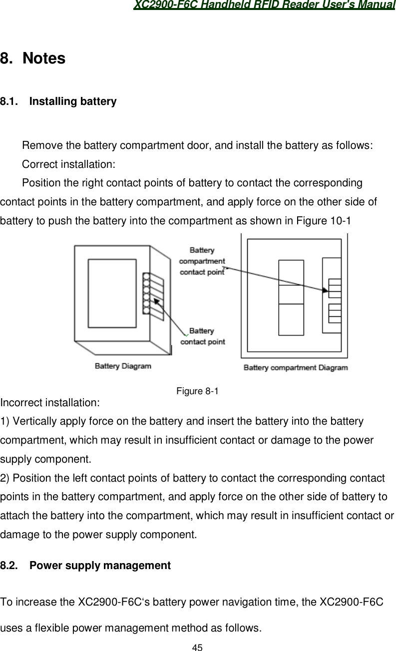
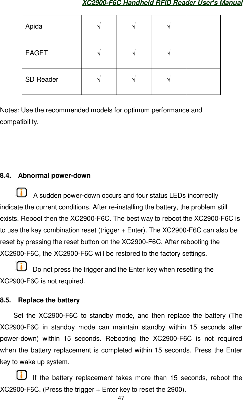
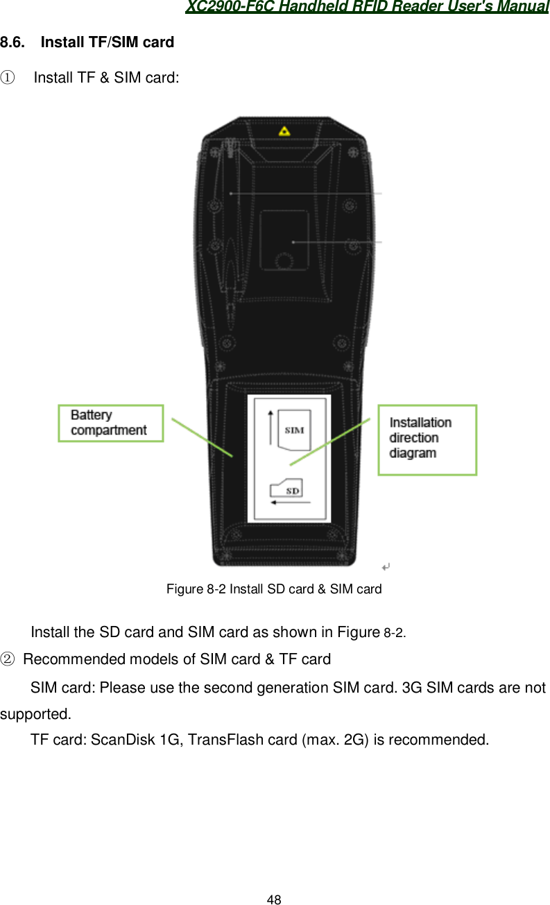
![XC2900-F6C Handheld RFID Reader User's Manual461) Power control: The reader system in default configuration will not automaticallyswitch to the standby mode. There are two ways to switch to the power-savingstandby mode.A) Press Enter key for about 2s, the system will switch to standby mode.M) According to the methods in [3.7 Configuring Power ManagementScheme], set and switch the system to the different power-saving mode.2) Module Control: in standby mode all modules are powered off; the systemswitches to low power consumption mode. However, due to the module’scharacteristics, when the XC2900-F6C switches from the standby mode to normaloperation, rebooting the Wi-Fi module is required.Note: to maximize the batter navigation time, charge the XC2900-F6C intime.8.3. Recommended USB storage device modelsMemoryModel Max. 1G 2G 4G NoteKingston-DataTravele Kingston101 KingMax aigoL8266/8206/8298 unis ](https://usermanual.wiki/Invengo-Information-Technology/XC2900-F6C/User-Guide-1621449-Page-54.png)
![XC2900-F6C Handheld RFID Reader User's Manual50 Click the menu on lower left corner in the main screen of the XC2900-F6C. Click the Start menu, click "System", and "Reboot" button. Press the RESET key to reboot the XC2900-F6C. Pull the trigger and press the Enter key simultaneously to reboot the XC2900-F6C. Why are the installed applications and settings missing after rebooting theXC2900-F6C? How to solve it?There are two common ways to reboot the XC2900-F6C, including"reboot the XC2900-F6C" and "hot start the XC2900-F6C". "Reboot theXC2900-F6C" corresponds to "cold start the XC2900-F6C."[Rebooting] is a hardware reset process. After rebooting, theXC2900-F6C will be fully restored to factory settings.[Hot start] is a software reset process during which the registry will berefreshed mainly for the import and export registry information. [Hot start]does not reset the hardware.The XC2900-F6C currently support [Rebooting] only. Click the "System"– click "Reboot" button or "unplug battery" will reboot the XC2900-F6C.The power consumption will be minimized when the XC2900-F6C enters“Standby” mode. To keep settings or install applications, do not rebootthe XC2900-F6C or remove the battery from the XC2900-F6C.Long press the red "Enter" key to enable the system to enter "Standby"mode.Backlight is off Check the backlight is turned down to a minimum. Check the pending button “Enter” is clicked.No sound Check the “Mute” button is on. Check the system volume is turned down to a minimum.Click on black screen, and the XC2900-F6C does not respond. Check if the standby mode is enabled: Click “Enter” to activate thesystem.](https://usermanual.wiki/Invengo-Information-Technology/XC2900-F6C/User-Guide-1621449-Page-58.png)