Invengo Information Technology YWGIT-R5678900 RFID R/W User Manual
Invengo Information Technology Co., Ltd. RFID R/W
users manual
*** Caution ***
Changes of modifications not expressly approved by the party responsible for
compliance could void the user’s authority to operate the equipment。
XCRF-500 Reader Series
Operation Manual
Shenzhen Yuanwanggu Information Technology Co., Ltd.

i
Content
Chapter 1: Introduction..........................................................1
1.1 System advantage .........................................................3
1.2 System capability characteristics..................................4
1.3 XCRF-500 reader series ...............................................5
1.4 Other needed accessories..............................................6
Chapter 2: Installation............................................................7
2.1 Appearance of XCRF-500 reader series .......................7
2.2 Front and Upper Panel..................................................9
2.3 Back Panel..................................................................11
2.4 Installation steps .........................................................12
2.5 Connect external antenna............................................13
2.6 External antenna installation.......................................14
2.7 Connect serial port of PC............................................15
2.8 Connect to external AC power supply........................15
2.9 Reader Test..................................................................17
2.10 Adjust antenna position.............................................20
2.11 Test for reading the information of tag.....................20
2.12 Test for writing the information of tag......................20
Chapter 3: RF communication.............................................21
3.1 Signal interference ......................................................21
3.2 Signal attenuation/reflection.......................................23

ii
3.3 Optimization of system performance..........................25
Chapter 4: Fault Diagnosis ...................................................29
4.1 Faults that can be solved by user himself ...................29
4.2 Contact customer service............................................32
1.Information of the Reader
2.Information of the Computer
4.3 Return of the Device...................................................34
Chapter 5: Performance Index.............................................37
Chapter 6: other explanation................................................39
6.1 Radio frequency (RF) radiation..................................39
6.2 Non promissory articles..............................................39
6.3 marketed method

1
Chapter 1: Introduction
The XCRF-500 reader series are electronic tag readers
developed by Shenzhen Yuanwanggu Information Technology
Co., Ltd. These readers are applicable to reading/writing
XCTF-5000 tag series that satisfies NCITS256-1999 protocol
and works within UHF frequency range, as well as compatibly
reading AMTECH’s UHF tag used in vehicle identification.
With its compatible electronic tags, XCRF-500 reader series
could be widely deployed in the areas like custom vehicle
automatic identification, urban vehicle automatic identification
management, highway non-stop toll, etc.
XCRF-600 reader can only read the tags that meet the proposal
of EM4223. XCRF-600 reader needs only to send RF power
to tags, one tag will send its ID information. XCRF-600 reader
can be widely deployed in the doorway management, etc.
XCRF-500 reader series includes 4 reader models:
XCRF-500W, XCRF-501W, XCRF-502W and XCRF-504W.
XCRF-500W is single-ported reader where only antenna 1 can
be connected with external antenna. XCRF-501W is
antenna-built-in reader, XCRF-502W is dual-ported reader,

2
both antenna 1 and antenna 2 of which can be connected with
external antenna. XCRF-504W is four-ported reader, antenna 1,
antenna 2, antenna 3 and antenna 4 of which can be connected
with external antenna. In the case that the reader you ordered is
multi-ported, it is necessary to connect the unused antenna
ports to 50Ω/20W dummy load in order to protect the reader.

3
1.1 System Advantage
From the point of data collection, radio frequency
identification system completely resembles bar code system. In
the course of data collection, bar code system adopts one-way
communication, i.e., bar code sensor (reader) reads information
from bar code in non-touch way. During such information
flowing, bar code is totally in a passive and subordinate
position and the communication is one-way, i.e., information is
transmitted to bar code sensor from bar code tag.
The shortcoming of bar code system is that, if damaged,
polluted, damped or located inside an article, the bar code
couldn’t acquire data because the reading range of sensor is too
short.
Data collection system composed of XCRF-500 reader series
and their compatible electronic tags, fundamentally overcomes
the above shortcoming of bar code system. The communication
between reader and tag is two-way, in which the tag makes

4
relevant response to reader’s demand. With two-way
communication, system could realize the function of reading
multiple tags within reading area.
Matched with appropriate antenna, the reading range of
XCRF-500 reader series could be over 7 meters.
1.2 System Capability Characteristics
ø Ability to read part of or all the data information of a
single tag;
ø Ability to read part of or all the data information of
multiple tags under the circumstance of no unpacking
and ordering;
ø Ability to screen specific electronic tag according to
the user-defined rules;
The super inquiry protocol followed by reader and electronic
tag enables reader to unerringly identify every electronic tag
within reading area and read each tag only once.
The unique protocol between reader and electronic tag decides
that when multiple tags are read, every tag spends the same
reading time, independent of tag quantity within reading area
(regarding XCTF-5000 electronic tag).

5
1.3 XCRF-500 reader series
XCRF-500 reader series are designed for reading and writing
UHF tag of XCTF-5000, while keeping compatible with
AMTECH vehicle tag.
XCRF-500 reader series provides 1 to 4 radio frequency
interfaces for external radio frequency antennas. Radio
frequency cable should employ low loss cable, and the length
of radio frequency cable equipped with reader is 10 meters.
Lengthening the radio frequency cable or using general radio
frequency cable will affect the reading/writing range of reader.
Note:
(1) Joint between radio frequency cable and reader is N-type
joint, connection of which should be tight and reliable.
Over-tight joint connection would damage the joint socket,
while a loose one would cause system performance decline
(reading/writing distance).
(2)Switching on the power and transmitting microwave prior to
disconnecting antenna might cause serious damage to the
system.
(3) Unused antenna port should be connected to 50Ω/20W
load.

6
1.4 Other Required Accessories
Besides reader and tag, IBM-compatible personal computer
system and interface software for reader are also needed to
build a integrated radio frequency identification system and
data collection system.
The minimum requirement for personal computer system is:
ø 9-firing pin RS-232 serial port;
ø Well adaptive to Windows 98/2000/XP;
Interface software for reader includes:
ø API Dynamic-Link Library for XCRF-500W reader
series;
ø API and demo software V1.1 for XCRF-500W reader
series;

7
Chapter 2: Installation
In this chapter we introduce the installation and testing of
XCRF-500 reader series. Before installation and testing,
operator should read the article of “radio frequency (RF)
radiation” (Section 6.1) of this handbook.
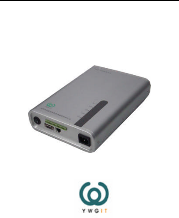
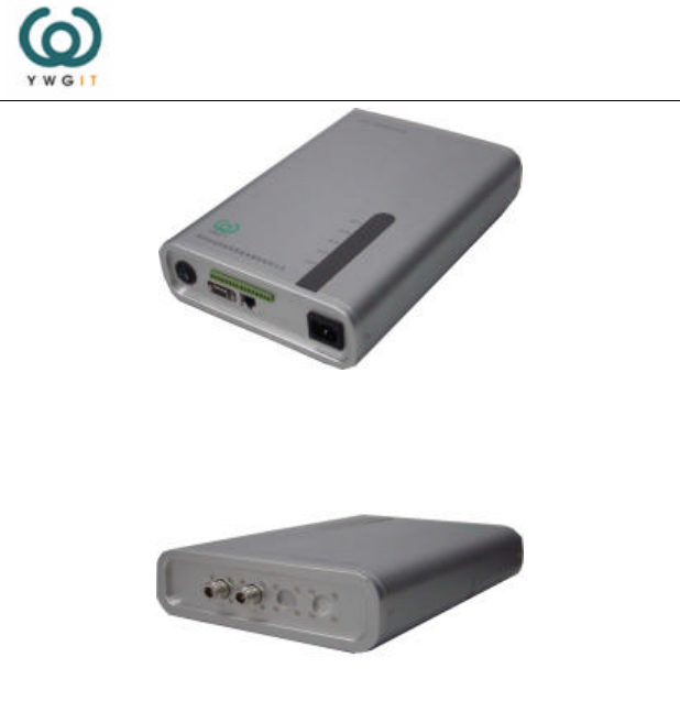
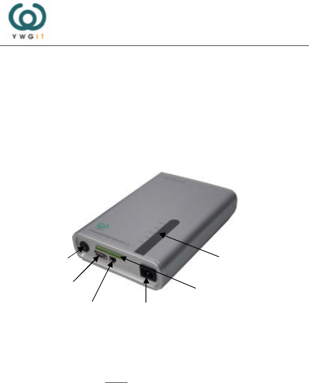
2.1 Appearance of XCRF-500 reader series
Appearance of XCRF-500 reader series is shown as figure 2-1
(a) and figure 2-1 (b). There are power switch , interface of
power supply, an serial interface, a 10M network interface and
a control interface on the front panels of XCRF-500 reader
series. There are 5 LED indicators for working status of reader
on the upper panels of XCRF-500 reader series. There are 2
N-joints which connect transmitting and receiving antenna of
reader, except that there are also 2 extend N-joints on the back
panels of XCRF-500 reader series.
8
Figure 2-1(a) Appearance of XCRF-500 reader series (front right)
Figure 2-1(b) Appearance of XCRF-500 reader series (right back)
9
2.2 Front Panel and Upper Panel
On the upper panel of XCRF-500W reader series there are 5
LED indicating the working status of reader. The indicators of
“Power supply” and “Power amplifier” are bicolour (red and
green), shown as figure 2-2.
Figure 2-2 Top panel of XCRF-500 reader series
The 5 LED on the front upper panel of reader indicats the
current status of power supply, power amplifier, connection,
communication and receiving. The meaning of each LED
indicator is detailed in table 2-1.
LED
Power switch
Series port
Network interface
Power supply interface
Control Interfa
ce

10
Table 2-1 Meaning of each indicator light on the front
panels of XCRF-500 reader series
LED indicator
Colour Status
Power Supply Green or red Light-up means reader start-up.
Power Amplifier
Green or red Light-up means that power amplifier
of radio frequency works.
Link Green Light-up means that network
interface connects correctly.
Activity Blue Light-up means exchanging data by
network interface.
Receive Green Light-up means receiving correct tag
information.
“Power supply” and “power amplifier”
light combination indicated function
Working status indication of
multiple antennas
Light status of
“power supply”
Light status of
“power amplifier”
Status indication
Green Green Mean that antenna 1 is working
Green Red Mean that antenna 2 is working
Red Green Mean that antenna 3 is working
Red Red Mean that antenna 4 is working
11
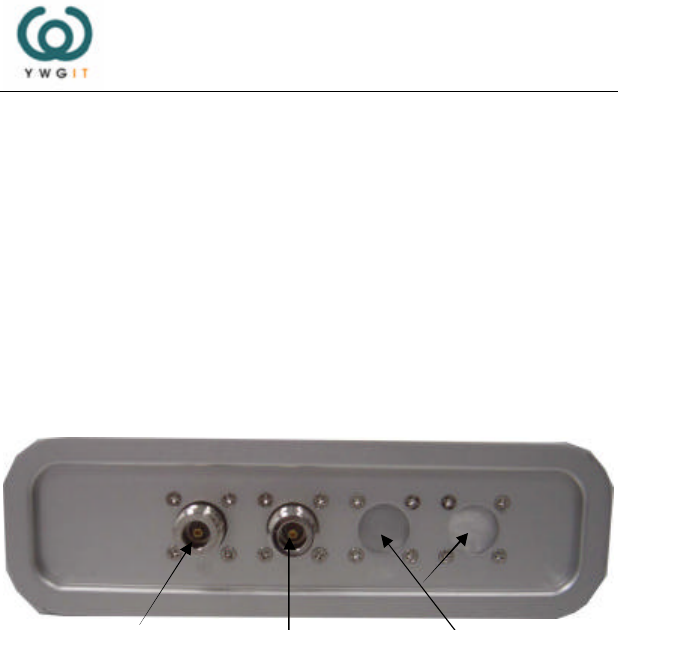
2.3 Back Panel
There are 2 radio frequency (RF) interfaces (N (Female))
which connect reader antenna,and two extent RF interface.
Only port 1 can be used for XCRF-500 reader, both port 1 and
2 can be used for XCRF-502W reader (see figure 2-3). The two
sperated ports provide the same function, they are worked
time-devided. In a period time only one port can transmit and
receive information simultanously.
Figure 2-3 Back panel of XCRF-500 reader series
Antenna
Port
1
Antenna
Port
2
Antenna
Extend Interface

12
2.4 Installation steps
Installation steps of XCRF-500 reader series are as follows:
(1) Reader installation: choose a position closer to antenna. If
located outdoor, the reader should be installed in a water-proof
case;
(2) Connect external antenna (see page 21);
(3) Install the antenna and make reader in the best working
status for reading/writing electronic tag (see page 23);
(4) Connect serial communication cable to the serial port of
personal computer (see page 25);
(5) Connect power supply (see page 26);
(6) Configure reader (see reader API interface and demo
software specification);
(7) Adjust antenna’s position (see page 31)

13
2.5 Connect external antenna
There are 2 N-type coaxial cable joints (Female) on the back
panels of XCRF-500 reader series to connect the external
antenna. Be sure that the installation of the antenna must be
performed by professional installers authorized by the
provider. Sketch map of connection between reader and
external antenna is shown in figure 2-4.
Low loss radio frequency cable with a standard length of 10
meters is recommended for the connection between reader and
antenna. Insert loss of the Low loss radio frequency cable
must be at least 1 dB and less than 2dB.When connecting
with antenna and reader, the cable joint should be tightly
screwed. In practical installation, a heat-contracted pipe should
be used to airproof the cable joint for protection once it is
screwed.
14
Figure 2-4 Connetion between XCRF-500 reader series and atenna
(Sketch map)
2.6 Install external antenna
External antennas of XCRF-500 reader series are usually
installed outdoors. The area that its wave beam covers is the
valid area for system reading/writing electronic tag.
Depending on the specific requirement on the application spot,
external antenna of reader could be either
horizontal-top-mounted or vertical-side-mounted . The angle
of inclination or rotation of antenna could be adjusted to enable
Antenna XCAF-11

15
the best reading/writing performance.
Usually XCRF-500 reader series should be used with linear-
polarized antenna (to avoid antenna loss). In a on-spot
installation, do pay attention to the polarization matching
between reader antenna and tag antenna, otherwise the
reading/writing range might be seriously affected.
2.7 Connect to PC serial port
XCRF-500 reader series provides RS232 serial interface. The
9th foot of the serial interface provides an output power of +5V
DC, which meets standard RS232 transmission, easily connects
to expanded USB interface module, connects to standard radio
communication module of WLAN802.11b protocol to meet the
requirement of radio data transmission within 10m, or connects
special radio communication module to meet the requirement
of radio data transmission within 200m.
In addition, XCRF-500 series readers also provide a 10M
network interface to meet the requirement of high-speed data
transmission.
2.8 Connect to external AC power supply
Follow the below steps to connect to AC power supply of

16
XCRF-500 reader:
(1) Make sure that the voltage is AC100V ~ 240V and working
frequency is 50Hz;
(2) Make sure that the switch of XCRF-500 reader series is off;
(3) Plug one end of the power line into the socket of AC power
supply, and another end into the triple-cored-cassette AC
power input of XCRF-500 reader series
(4) Turn on the switch on the front panel of XCRF-500 reader
series. After a beep, power supply indicator lights up, then
the reader is initialising, and the system is standby after
finishing initialising process.
Note:
When XCRF-500 reader is in default status, the system is in
standby status after start-up. The reader does not transmit radio
wave when it is initialising or standby (radio power amplifier is
off). Only after connected to antenna or load and receiving
‘Read/Write tag’ command from PC or ‘Enable Power
Amplifier’ command, Power Amplifier of reader turns to
working status.
Caution: It is harmful for readers to enable the Power
Amplifier with the absence of the connection to antenna or

17
dummy load.
2.9 Reader Test
Testing for XCRF-500 reader series includes:
(1) Power Amplifier enable test: the indicator “PA” on the front
panel of reader lights up after the Power Amplifier is

18
enabled.
(2) Power Amplifier disable test: Power Amplifier is off after
the system start-up and initialisation. Power Amplifier
could be disabled by “Disable Power Amplifier” command.
The indicator “PA” on front panel of reader will be off after
Power Amplifier is disabled.
(3) Electronic tag reading test:
² Single tag reading test: test reading the tag ID number,
partial or entire data in designated electronic tag;
² Multi-tag reading test: test reading multi-tag ID
number, and the memory data of the designated
electronic tags among multiple.
(4) Electronic tag write test:
² Single tag writing test: read tag ID number; update the
data in designated position or total data in tag memory;
writing-protection test.
² Multi-tag writing test: read multi-tag ID number, read
or update the data in designated tag memory;
writing-protection test.
(5) Read-range test: Read single tag to test its read-range, and

19
adjust the position and inclination/rotation angle of antenna.
This test could be done from near to far or reversely;
(6) Write-range test: A signal-tag test usually done after read
test. It should be conducted from far to near.
The equipments and software required for read test are:
(1) XCRF-500 reader series
(2) Antenna: XCAF-11, YWGIT, 6dBi
(3) RF cable: 1dB<Insert loss<2dB
(4) AC power supply and power socket;
(5) PC with WINDOWS98/2000 and 9Pin Serial Port;
Test software for XCRF-500 reader series: XCRF-500 reader
series API and demo software V1.1.
(6) Attached CD.

20
2.10 Adjust antenna position
Determine a rough read-range on the application spot, then
locate and fix the antenna. Follow the procedure of reading test
for XCRF-500 reader series to adjust the inclination /rotation
angle of antenna to get an optimal read-range.
Last, fix the installation position and antenna angle.
2.11 Test for reading tag information
Fulfilled by “XCRF-500 reader series API and demo software.
2.12 Test for writing tag information
Fulfilled by “XCRF-500 reader series API and demo software”.

21
Chapter 3: RF Communication
Generally, the system performance of the devices employing
radio communication technology is very sensitive to signal
interference and attenuation. This chapter addresses the
optimisation issue of radio frequency communication between
XCRF-500 reader series and electronic tag, which includes:
(1) Signal interference
(2) Signal attenuation
(3) Optimisation of system performance
3.1 Signal interference
Signal interference is the radio frequency (RF) signal caused
by the information exchange between reader and electronic tag.
Signal interference might seriously impair reader’s ability to
read the data of electronic tag. The flashing of receiver
indicator indicates the existance of interference signal, and the
flashing frequency represents the extent of signal interference.
The sources of interference signal include:
ø Radio frequency (RF) system, e.g., RF local-area
network, nearby interactive identification system;
ø RF signal radiated from security gate, garage door or

22
other devices;
ø Radiation source of other radio frequency (RF);
The influence of these interference sources can be eliminated or
reduced by adjusting the installation position and direction of
the reader and antenna.
When radio frequency (RF) interference or noise exists, the
performance of reader system (exchange data with electronic
tag) will dramatically decline. The reader can only “receive”
one signal at any time, not able to differentiate the unexpected
“noise” and expected “useful RF signal”.

23
3.2 Signal attenuation/reflection
Signal attenuation refers to the natural attenuation of signal
strength with the distance increasing. Meeting blocks during
signal transmission might also cause attenuation.
The blocks probably affecting the transmission of radio
frequency signal include:
ø Close-ended space comprised of concrete wall, floor
and ceiling;
ø Metal surface surrounding antenna or tag;
ø Water or other liquids surrounding antenna or tag;
Almost every object (furniture or blocks) in the path of
transmitting radio frequency signal will cause attenuation to
different extent. With an elaborate adjustment to the installation
position, the attenuation of radio frequency caused by blocks
can be lessened to possible least.
The reflection from the metal or metalized surface back close
to the electronic tag can affect the signal attenuation. In some
situation, this could be solved by slightly increasing reading
distance, but at the same time some ‘dead corners’ will appear

24
within reading area. When the electronic tag is positioned in
dead corners, the communication between reader and tag will
be very poor.

25
3.3 Optimisation of system performance
Generally, it is impossible to precisely predict the system
performance of the reader under any given circumstance (the
root is the complexity of electromagnetic radiation, including
the frequency stability of signal source, the direction of antenna,
antenna side-lobes and the environment). However, the
suggestions below are instructive to optimising the system
performance in practice.
ø Elaborately design and install the antenna of reader.
The standard length of radio frequency cable between
antenna and reader is 10 meters. Over-lengthy radio
frequency cable will bring about attenuation of both
transmitted signal and received echo signal, which will
shorten the reading range.
ø Change in antenna connection or antenna type will
significantly affect the system performance.
ø Take the surrounding into consideration:
construction materials, office hours, windows and pipe
configuration, etc. Radio frequency field mode and

26
ø reading range could be affected by the nearby metal
articles like the household appliance, equipments,
metal frames, etc.
ø Make sure that the objects attached with the electronic
tags to be identified stay within the valid reading area
for longer than 10 milli-second (regarding XCTF-5000
electronic tag).
ø The polarization direction of the reader antenna shall
be the same as that of the electronic tag antenna. If the
reader antenna is linearly polarized, the electronic tag
could be rotated by 90 degree to find out minimum
and maximum reading range.
ø If the reader antenna is round polarized, the electronic
tag may be rotated by 360 degrees in the plane facing
the reader antenna without affecting the reading range.
ø In the case that the electronic tag is vertical to the
reader antenna, the reader-writer antenna can’t
communicate with the electronic tag, however it is
polarized.
ø The optimal length of electronic tag antenna is related
to the non-conduct material in which the antenna is
packed or embedded. The basic idea is: for the
ø electronic tag packed in non-conductor (its dielectric

27
constant is usually larger than that of the air, and thus
its effective wave length is shorter than that in the air),
if its effective electrical length is adjusted to the
optimal length in the air (the corresponding reading
distance to the reader-writer is the longest), and when
the antenna is packed in the non-conduct material, the
electrical length of the antenna should be shortened to
parallel the optimal effect in the air. On the contrary, if
the electrical length of the antenna is adjusted to the
optimal, then its optimal electric length in air should
be increased.
ø To avoid the mutual interference between multiple
electronic tags installed on one object, any two
electronic tags should keep enough distance to each
other. The interference between multiple electronic
tags will occur when the distance between two
electronic tags is less than 10cm and their distances to
the antenna are equal.
ø Keep the bare or unpacked electronic tags away from
chemicals. Some chemicals, such as alcohol, will not
affect electronic tags in the normal temperature, but
will somewhat cause corrosion when the temperature
gets higher,

28

29
Chapter 4: Fault Diagnosis
This chapter introduces the solutions, service information and
repair issue of devices malfunction and abnormal situation.
4.1 User-solvable Problem
Table 4-1 lists some user-solvable problems regarding the radio
frequency identification system composed of reader and
electronic tag.
Table 4-1 Fault diagnosis for XCRF-500 reader series
Problem Likely cause Solution
The power supply
indicator doesn’t
light up after the
reader is switched
on.
The socket of AC
junction box
malfunction.
Apply another AC
electrical appliance
such as a bulb to the
socket to see if it
works. If not, please
check out the power
supply or replace the
socket.

30
The AC junction box
may be controlled
by one switch
Connect to control
switch, or select one
junction box with
control switch
Power on the control
switch or select a
junction with control
switch
The power amplifier
indicator of
doesn’t light up.
The power amplifier
of reader is not
enabled.
Enable the radio
frequency power
amplifier with the
‘Enable power
amplifier’ command
of the test software
Disconnection
between reader and
PC.
Connect the reader
with PC using serial
port or network
cable.
The indicator of
Power amplifier
doesn’t light up
Reader isn’t switched
on
Switch on the
reader.

31
The power amplifier
disabled, no RF
power output.
Enable the power
amplifier with the
‘Enable power
amplifier’ command
of the test software
No tag in the reading
area of reader.
Make the tested tag
closer to the reader
antenna.
The tags in the
reading area of the
reader are damaged.
Replace the
damaged tags and
retry.
The indicator
“Receive” doesn’t
light up
The direction of
electronic tag in
reading area doesn’t
match the polarization
direction of the
reader’s antenna
Make the electronic
tag face the reader’s
antenna and turn it.
The indicator of
power supply
doesn’t light up
No AC power output
Check the external
AC power supply

32
4.2 Contact customer service
Please contact the company’s customer service centre in case
users get any problems beyond those in section 4.1 and can’t
figure out solutions.
Before contacting our client service centre, please make
following information available:
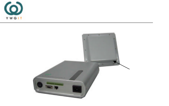
◇ Information of Reader
ø Model of the reader;
ø Serial number of reader (at the bottom of the reader);
ø Any alterations to the reader or tag;
ø Position of reader;
ø Information about the application software of reader.
◇ Information about Computer
ø Brand and model of computer;
ø Processing speed and available RAM;

33
ø COM interface used;
ø Operating system.
◇ Contact our client service centre:
Shenzhen Yuanwanggu Information Technology Co., Ltd.
Free Telephone Call:800-891-0036
Email: sales@ywgit.cn

34
4.3 Device Return
If the client service staff decides that user should return the
reader for reparation, the client service representative will give
user a RMA(Return Merchandise Authorization)。 Please
record this RMA number on the packaging outside and
meanwhile place a note bearing this number inside the
packaging so that the returned merchandise could be promptly
handled.
Please follow the steps below to return the reader for
reparation:
(1) Pack the reader and its accessories carefully and then put
them into the original static-proof foam packing case. If the
original packing case is missing, please use a protective
packing case.
(2) Use filling materials to cover the content in the case;

35
a) Put a note bearing the RMA number in the case;
b) Write the RMB number and the word “FRAGILE” on
the outer surface of the case;
c) Mail the returned merchandise to the following
address:
Postal Code: 518057
3/F, Building T2-B, High-Tech Industrial Park South,
Shennan Road, Shenzhen
Shenzhen Yuanwanggu Information Technology Co.,
Ltd

36

37
Chapter 5: Performance Index
Performance indexes of XCRF-500W reader series are as
follows:
ø Reading and Writing Perforemance:
n The reading and writing range is related to the
output power of reader, antenna and electronic
tag;
n Under regular configuration: EIRP=36dBm
² Maximum Reading Range=7m;
² Maximum Writing Range=5m;
n Single Character(16bits)Reading Time: 10ms;
n Single Character(16bits)Writing Time: 30ms;
n GPRS Module Interface
ø Lighting Emitting Diode (LED): Power Supply
indicator(red or green), Power Amplifier indicator
(red or green), Link indicator (green), Activity
indicator(blue), Receive indicator (green);
ø Communication Interface:RS232 or 10M network;
ø Serial Transmission Rate:19200bps;
ø Regulation on DB9 Pin: standard RS232 definition,
the 9th pin for +5V output;

38
ø Voltage:100V ~ 240V/50Hz
ø RF Output Power:less than 1W
ø Power Consumption:less than 30W
ø Maximum Length of Serial Port Cable:10m
ø Dimension:296×200×65mm(L*W*H)
ø Weight: less than 2.5 kg
ø Operating Temperature: -10℃~+50℃
ø Storage Temperature: -20℃~+70℃

39
Chapter 6: Other Items
6.1 Radio frequency (RF) radiation
When reader is working (radiating microwave power), the
engaged people should keep at least 30cm away from the
antenna to meet the requirement stipulated by the US FCC
clause for the allowable radio frequency (RF) radiation that
human body is exposed to.
This item aims at the on-spot installation and debugging of the
equipment.
6.2 Non-promissory articles
Any radio-emitting devices including this device may cause
interference to the operation of medical device without
appropriate protection. In this case, please consult the relevant
medical equipments vendor for solution. The operation of this
device may also affect other electronic equipments.
6.3 Marketed method
The device is not available in the general public at the typical retail
stores and not available on the web. The device is custom-built, so it is
only available if customers purchase.

40
Shenzhen Yuanwanggu Information Technology Co., Ltd.
Address: Floor 3, Building T2-B, High-Tech Industrial Park
South, Shennan Road, Shenzhen

41
Postal Code: 518057
Tel: 0755-26711633 26711690
Fax: 0755-26711693
Website: http://www. ywgit.cn
E-mail: sales@ywgit.cn