Invengo Information Technology YWGIT-R5678901 RFID READER User Manual
Invengo Information Technology Co., Ltd. RFID READER Users Manual
users manual

※※※CAUTION※※※
changes of modifications not expressly approved by the
part responsible for compliance could void the user,s authority
to operate the equipment。

XCRF-804 Interrogator User manual

Table of Contents
1 INTRODUCTION ..................................................... 2
2 PERFORMANCE PARAMETER ............................................ 5
2.1 GENERAL FEATURES...................................................5
2.2 KEY FEATURE .......................................................5
2.3 TECHNICAL SPECIFICATION .............................................5
3 DESIGN FUNDAMENTALS .............................................. 6
3.1 DEVICE COMPOSE ....................................................6
3.1.1 RF unit: .....................................................6
3.1.2 Baseband unit: ...............................................7
3.1.3 Power unit: ..................................................7
3.1.4 data interface unit: .........................................7
3.1.5 case unit: ...................................................7
3.2 FUNDAMENTAL WORKING PRINCIPLE .........................................7
4 USAGE AND OPERATION .............................................. 8
4.1 INTERRORGATOR CONNECTION .............................................8
4.2 INTERRORGATOR USAGE AND OPERATION......................................8
5 USUAL FAILURE ANALYSIS AND EXCLUSION ............................. 8
6 OTHER NOTICE ..................................................... 9
6.1 PRODUCTION WARRANTY ................................................9
6.2 SAFETY NOTE .......................................................9
1 Introduction
Thank you for using XCRF-804 interrogator made in Shenzhen Invengo
Information Technology Co. Ltd. The interrogator can offer stability and reliability,
while strictly following the EPC C1G2 recommendation..
Front panel and rear panel layout
XCRF-804 interrogator layout as below: figure 2-1:
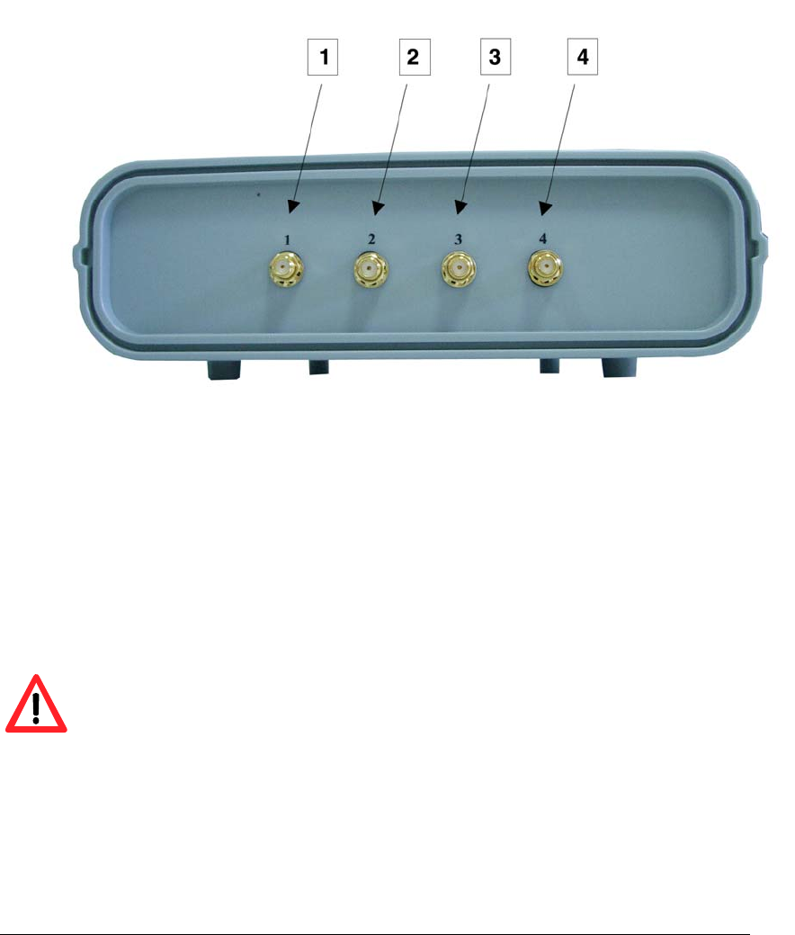
figure 2-1 XCRF-804 interrogator front panel layout
1-antenna port1;
2-antenna port2;
3-antenna port3;
4-antenna port4;
Note: Every antenna interface must connect with an antenna or 50 ohm load
before the interrogator power up. otherwise the interrogator will be damaged.
XCRF-804 interrogator rear panel figure 2-2:
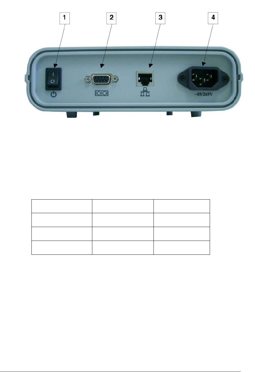
figure 2-2 XCRF-804 interrogator rear panel figure 2-2
1-power switch;
2-RS-232 serial port, a physical interface between a computer and interrogator.
The pin no, signal name and direction list as below. And the pin number is same as
the number showed on DB9 connector.
pin signal direction
2 RXD input
3 TXD output
5 Ground ground
3-Network Interface between a computer and interrogator. Plug one end of the
cable into the RJ45 jack on the back of your PC. Plug the other end into RJ45 port
on the interrogator. Device provides 10M/100M self-adaptive Ethernet interfaces.
4-AC INLET;
XCRF-804 interrogator surface as figure2-3:
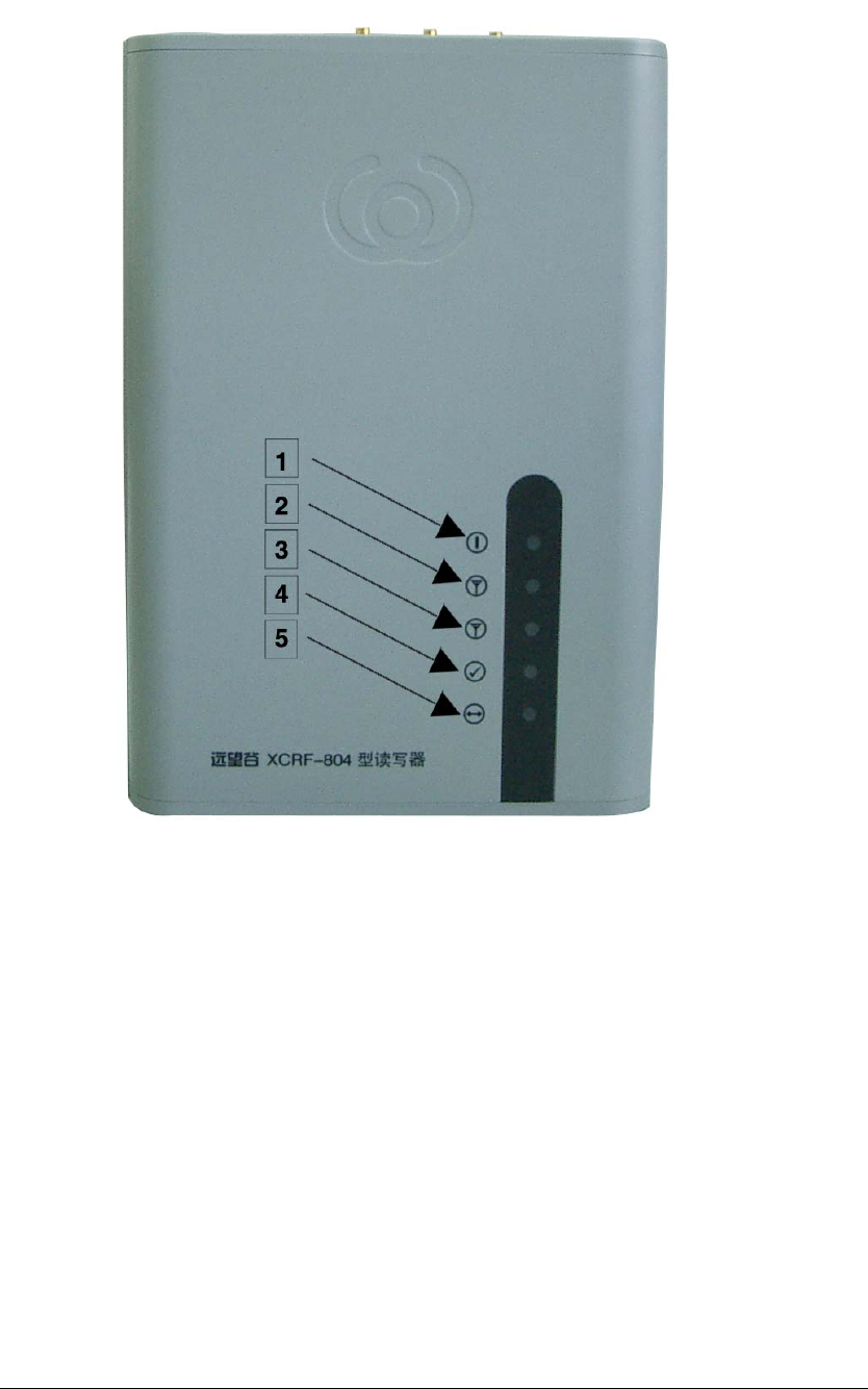
figure 2-3
XCRF-804interrorgator surface
1-Power/Power Amplifier Indicator, two-colour light(green or red),green light
indicates that the interrogator power on. Red light indicates the interrogator power
up;
2-antenna1/3,two-colour light(green or red),green light indicates that the antenna1
of interrogator is working, red light indicates that the antenna3 of interrogator is
working;
3-antenna2/4,two-color light(green or red),green light indicates that the No2
antenna of interrogator is working. Red light indicates that the No4 antenna of
interrogator is working;

4-Decode /error, two-colour light(green or red),green lighting indicates that the
interrogator read the tag data correctly. Red lighting indicates that the interrogator
read tag data error;
5-communicate/connect, two-colour light(green or red),green lighting indicates
that the interrogator is transmitting data to PC via Network Interface. Red lighting
indicates that the interrogator established a network connection to PC successfullly;
2 Performance Parameter
2.1 General Features
·Operating temperature:-10℃~+60℃(14℉~+140℉)
·Storage temperature:-20℃~+70℃(-4℉~+158℉)
·Operating humidity:20%~95%
·Power supply voltage:AC:85V~265V/200mA
·Size:28.8 x 20.4 x 6.8cm(11.3 x 8 x 2.8inches)
·Weight:about1.25Kg(2.97lb)
2.2 Key feature
·Protocol:EPC Global Class1/Gen2/ISO 180006B
·Tag data rates:40kbps
·Number of antenna:up to 4 , electronically switched
·Antenna port isolation:≧22dB
·Transmitter type:On/Off Keying
·Usable channels:50
·Occupied frequency bandwidth:<400KHz
2.3 Technical specification
·Frequency of operating:902MHz ~928MHz
·Output power:1.0Watt(+30dBm),20dB digital Control range, minimum interval
0.5dB
·Frequency stability:≦±5ppm
·Operating mode: fixed-frequency /frequency hopping selective
availability.maximal optional frequency number is 50pcs, frequency interval is
500KHz.
·Maximal reading distance up to 3.5~4.5m (11.48~14.75feet)(EIRP=36dBm,related
to tags.)
·Write distance:Distances up to70% of the read distance under the same condition.
·Multi-tag reading rate:≧60 pcs/second(it’s related to protocol)
3 Design fundamentals
3.1 Device compose
As figure 4-1 and 4-2,XCRF-804 interrorgator has 5 parts:RF unit,
baseband unit,power unit、data interface unit、case unit.
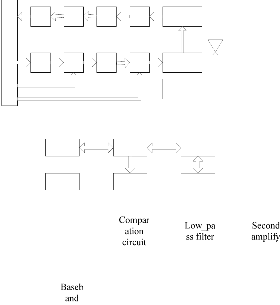
figure 4-1 interrogator RF unit fundamental block diagram
figure 4-2 interrogator baseband unit fundamental block diagram
3.1.1 RF unit:
→The RF unit receive baseband signal and modulate carrier,then amplify the

modulated carrier signals and transmit the signals by selected antenna.
→The unit receive the back scatter signal from the RFID tag.After demodulating ,
amplifying ,comparing the signals ,the unit transmit the signals up to baseband unit.
→The unit adjust output power and frequency of the antenna interface under the
control of the baseband unit.
3.1.2 Baseband unit:
→The unit receive data & command from PC via RS-232 interface,or send data &
results to PC ;
→The unit transmit control signals of tags to RF unit;
→The unit accept tag signals from RF unit, modulate signals and checkout;
→The unit can modify or query configure information of interrogator under the
control of PC command ;
3.1.3 Power unit:
→converts incoming alternating current (AC) to direct current (DC),out DC power
supply for the integrated equipment.
3.1.4 Data interface unit:
→Standard connector to connect the COM port ,network and power interface with
the rear panel of the integrated equipment ;
3.1.5 Case unit:
→The interrorgator case is made of molded-in ABS/PC. And the anti-static coating
was sprayed over the inner surface of the case;
3.2 Fundamental working principle
The complete RFID system is consist of XCRF-804 interrogator, antenna, tags,
and pc.
The baseband send the command to RF unit under the control of PC.RF unit
send signals to tags according to the tag type. When the tag is activated, it sends out
its number as well as other information .
The tags' response signals was amplified and shaped by the received-data

circuit. Then the signals was send to baseband unit. The baseband will decode the
received signal and then sends to PC via the communication interface of the
baseband unit.
The transmitting part of the RF unit will take the function of carrier generation,
carrier modulation, amplification and emission. The receiving part of the RF unit
will take the function of demodulation, amplify , compare etc.
The FPGA part of baseband will take the code/decode function to tag data.
MCU will take the function of communication with PC.
4 Usage and operation
4.1 Interrogator connection
There are 4 antenna port on the XCRF-804 interrorgator .The output port of
antenna interface is SMA plug.
You can find antenna Cable with reversed SMA-Plug to N-Plug Connector in
the product accessories. Joint the antenna SMA plug to the SMA interface of
interrorgator and tight the bolt. The fit another port of the antenna cable with proper
antenna.
4.2 Interrogator usage and operation
Connect the device as stated above, and the interrorgator will work under the
control of PC command. Our company provide API function and interrogator
demo software .User can use the software to test the interrogator. Please read user
manual of the interrogator demo software to get the information about test procedure
and test method.
5 Usual failure analysis and exclusion
·When the interrorgator is power on the signal lamp is not lighted:
→power fault: check if the input alternating current power is normal. The
alternating current voltage should between 85V~265V;
→If the other signal lamp is light, there is MCU or FPGA fault in the device. Once
you meet this problem, you can only contact with Invengon company to repair the

device;
·Can't read tag data:
→Please check if the serial port or the network cable is connect to the interrogator
correctly. If the cable is not joint firmly, interrogator can not get command from
PC.
→If the power amplifier signal lamp is light ,user need to check if the antenna SMA
connector is screw down, or if the tag is fault. But if the power amplifier is not
light, maybe the FPGA or MCU is fault. User should contact Invengo company
to repair the device;
6 Other notice
6.1 Production warranty
The warranty: period of our products is 2 years from delivery . If a defective is
found due to material processibility qualified problems of the product , we will
perform warranty commitment. Invengo company will decide whether repaire or
replace the fault product with certain qualified problem.
If a problem occurred is because the user's operation environment is not accord with
the product Specifications, or a problem occurred due to installation reasons, we will
not perform warranty commitment. we may charge the maintenance costs.
6.2 Safety note
When interrorgator is working (emitting microwave),person who install or
operate the device should be 30cm away from antenna to meet the FCC safety
standards requirement about maximal tolerant radiation human body can take.
The item should be carry out when user intall or operate the interrorgator.
Not undertake item:
Any RF device, include this interrogator , maybe disturb the medical device
without correct protection. If you face this problem , you should listen to the counsel
of medical device manufactory . This interrorgator may disturb other device when

working .
Invengo Information Technology Co. Ltd.
Add:3/F,No.T2-B High-Tech Industrial Park South,Shenzhen.
Zip Code:518057
Tel:0755-26711633 26711690
Fax:0755-26711693
http://www.yuanwanggu.com.cn
http://www.ywgit.cn
http://www.invengo.cn
http://www.invengo.cc
E-mail:sales@yuanwanggu.com.cn