Inventec Appliances CP-108 PCMCIA Wireless LAN Card User Manual CP108 User s Manual 0 1
Inventec Appliances Corp. PCMCIA Wireless LAN Card CP108 User s Manual 0 1
Users Manual
Revision: 0.1
CP-108 Wireless LAN Card User’s Manual Date:01/15/2002
Page 1 of 17
CP-108 Wireless LAN PCMCIA Card
User’s Manual
Inventec @ppliances Corp.
IMPORTANT
This document contains important Information, please read it carefully before using this
product.
Copyright Inventec @ppliances Corp. 2002

Revision: 0.1
CP-108 Wireless LAN Card User’s Manual Date:01/15/2002
Page 2 of 17
Revision History
Date By Revision Comments
01/15/2002 Danny Shih Draft Initial Draft
1.
Revision: 0.1
CP-108 Wireless LAN Card User’s Manual Date:01/15/2002
Page 3 of 17
1. Introduction
The CP-108 is a wireless PCMCIA NIC Card. 2.4GHz Direct Sequence Spread
Spectrum (DSSS) Wireless PCMCIA NIC Card, Type II, Plug and Play PC Card 2.1
Compliant. Supports ad-hoc (peer to peer) and infrastructure (communication to
wired networks via Access Points), the Firmware implements the full IEEE8.2.11b
wireless LAN MAC Protocol. It supports BSS and IBSS operation under Function
(PCF). The low level protocol function such as RTS/CTS generation and
acknowledgment, fragmentation and de-fragmentation, and automatic bacon
monitoring are handled without host intervention. Active scanning is performed
autonomously once initiated by host command. Host interface command and
status handshakes allow additional firmware function specific to Access Point
applications are also available.
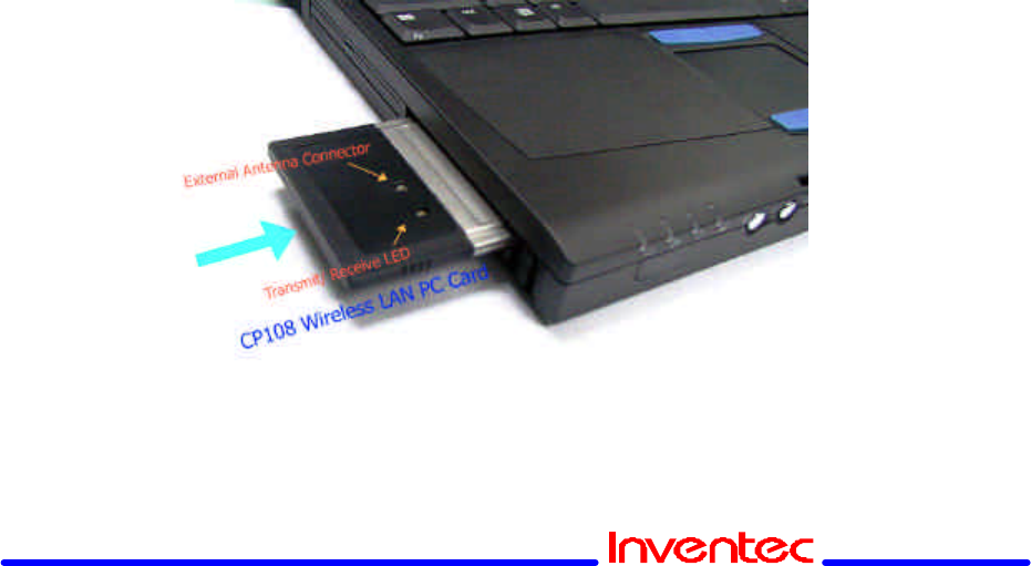
2. Hardware Installation
Insert your CP108 PC Card 2
1. Unpack your CP108 PC Card kit and verify that all items are present,
as described in “Kit Contents”.
If any of the items described appear to be damaged or missing, please
contact your supplier.
2. Insert the CP108 PC Card into the PC Card slot of your computer.

Revision: 0.1
CP-108 Wireless LAN Card User’s Manual Date:01/15/2002
Page 4 of 17
Ifyou wantto installthe PCCard into a desktopcomputer,usean
ISA Adapter or PCI Adapter.
3. Install Drivers
1. Before You Start the Installation 2
Beforeyou startthe installation,you areadvisedto keep theWindows
CD-ROM or software diskettes close at hand. If your computer came with a
factory-installed Windows operating system, these files will be stored on
your computer’s hard disk, in the form of cabinet (*.cab) files.
NOTE:
If you are upgrading from an earlier version of the CP108
Miniport driver, please read Appendix B of the CP108 PC Card -User’s
Guide provided on the CP108 Software CD-ROM.
2. WhatYou Need to Know 2
Installing a CP108 PC Card requires the same level of expertise that you
would need to install a standard Ethernet network adapter card. It is
assumed that you have a working knowledge of standard Windows 95/98
operations and of installing network adapter cards. Refer to the Windows
Help when necessary (on the Windows task bar, press the Start button and
3. Driver Installation for Windows 95/98
Windows 95/98 operating systems support “Plug & Play” for PC Cards. Once
you insert the CP108 PC Card into your computer, these operating
systems will automatically:
n Detect the card, and enable the CP108 Driver, or
n Start the Add New Hardware wizard and prompt you to install the driver,
when the operating system cannot find the required driver.
This would typically occur when inserting the CP108 PC Card into
your computer for the very first time.
To install the driver proceed as follows:
1. IfWindows starts theAdd New Hardware wizard follow the instructions of
the New Hardware Found wizard to installthe drivers.
n When you are prompted to locate the driver installation files:
— Select the CP108 CD-ROM that was included with your

Revision: 0.1
CP-108 Wireless LAN Card User’s Manual Date:01/15/2002
Page 5 of 17
PC Card kit and.
— If you downloaded the drivers from the Inventec website
navigate to the folder that matches your Operating system.
Windows 95:D:\Drivers\Win_95
Windows 98:D:\Drivers\Win_98
Windows 2000:D:\Drivers\Win_2000
When finished installing the drivers, Windows automatically opens the
Add/Edit Configuration Profile window.
2. Continue with setting the basic parameters.
4. PRISM WLAN Configuration
1. Introduction
The “Wireless NIC”, model WL271, is a PC peripheral that designed for PC user to
extend the PC’s capability of mobile communication in office environment. The
form factor is small to adapt for the PCMCIA type II socket that most of notebook
PC had. With the cooperation with AP201, Wireless LAN Access Point, notebook
PC user can communicate with those PCs user already existed in IEEE 802.3
networking environment in comfortable mobility.
The WL271 Wireless Local Area Network (WLAN) Interface card enables high-
speed access to Internet and intranet assets without wires. This card uses the
IEEE 802.11 protocol to enable communications between the host computer and
either another host computer or a network, using the 2.4GHz ISM Radio Band for
the communications medium. The host computer uses the WL271 Wireless LAN
card for communications in the same way that it would use an Ethernet Network
Interface Card.
2. Utility Installation
The PRISM WLAN Configuration Utility is installed simultaneously with the driver
by executing the ‘PRISM for Windows.exe ’file.
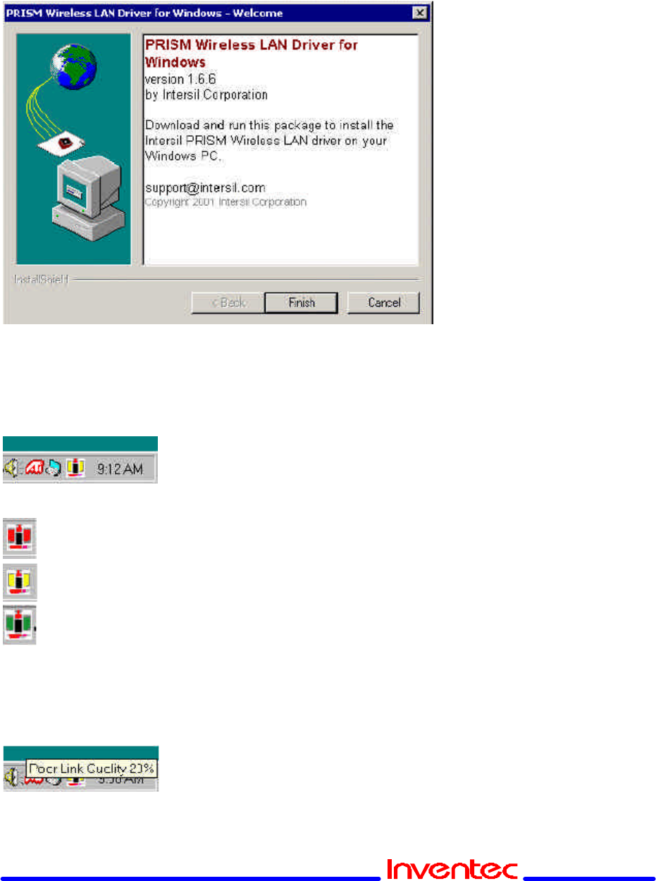
The following illustration shows this program’s initial screen: When you click the
Finish button in this screen, both the driver and the Configuration Utility are
installed on your computer.
Revision: 0.1
CP-108 Wireless LAN Card User’s Manual Date:01/15/2002
Page 6 of 17
3. System Tray Icon
After the installation of the PRISM WLAN Configuration Utility, its icon appears in
the System Tray in the bottom right corner of your desktop.
The color behind the Intersil logo indicates the link status.
Red indicates no or very poor link quality.
Yellow indicates a usable but weak link.
Green indicates a strong link.
You can also view the status of the link by placing the cursor over the
Configuration Utility icon, as shown in the following illustration. This illustration
indicates that the PRISM WLAN Card is able to communicate, but that the signal to
the radio is weak.
Revision: 0.1
CP-108 Wireless LAN Card User’s Manual Date:01/15/2002
Page 7 of 17
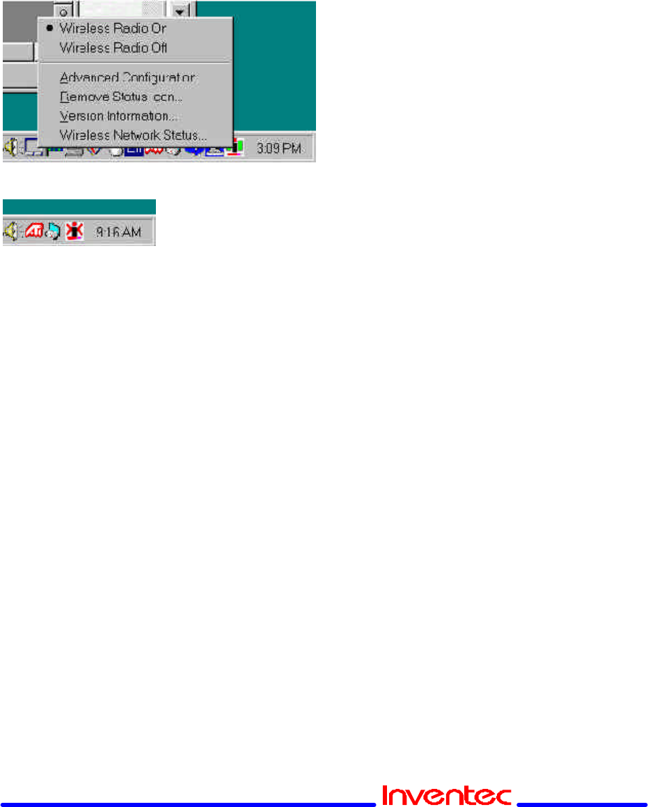
Icon Menu
Clicking the left mouse button on the System Tool Tray Icon displays a menu
similar to the following illustration:
The first two items in this menu let you turn the wireless radio on or off. When the
wireless radio is turned off, the following icon appears in the system tray.
?? Advanced Configuration… launches the Configuration Utility with the
Configuration menu displayed, as discussed in the following section. This lets
you set configuration parameters, which change the behavior of the PRISM
WLAN card.
?? Remove Status Icon… removes the System Tray Icon. The driver continues
to operate the card in the last commanded configuration. The next time you
power up your computer, the configuration utility will return. You can also
restart the Configuration Utility from the Start Menu by selecting Programs and
PRISM Wireless LAN Configuration.
?? Version Information… launches the Configuration Utility with the About menu
selected, giving the revision level of the driver, configuration utility and
firmware.
?? Wireless Network Status… launches the Configuration Utility with the Link
menu selected. This shows the link status, including Signal Strength and Link
Quality. If you click the right mouse button on the System Tool Tray Icon, a
Profile menu appears. This menu lets you quickly load an existing profile or
create a new profile, as explained in the following section.
4. Starting the Configuration Utility
You can launch the Configuration Utility by clicking the left mouse button on the
Configuration Utility icon and selecting Advanced Configuration… If the
Configuration Utility icon is not displayed in the System Tray, you can restart the
Revision: 0.1
CP-108 Wireless LAN Card User’s Manual Date:01/15/2002
Page 8 of 17
Configuration Utility from the Start Menu by selecting Programs and PRISM
Wireless LAN Configuration.
The Configuration Utility consists of four menus: Configuration, Encryption, Link,
and About. The following sections describe these menus in detail.
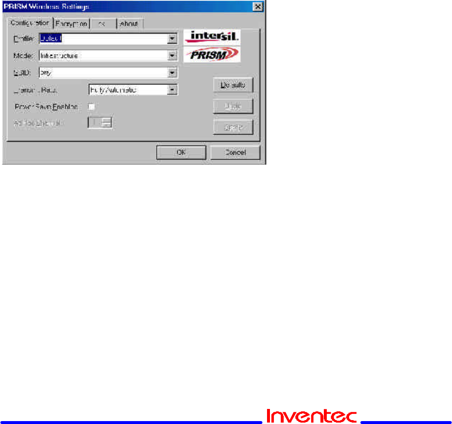
5. Configuration Menu
The Configuration menu lets you specify the operating parameters for your PRISM
WLAN Interface card. When you first start the Configuration Utility, this menu is
displayed. If another menu is displayed, you can display the Configuration menu by
clicking on its tab in the Configuration Utility panel.
Setting the Profile
A profile is a named set of operating parameters for your PRISM WLAN Interface
card. The Profile field lets you set values for all parameters by selecting a
previously defined profile. Click the down arrow at the right of the Profile field to
display the available profiles for your PRISM WLAN Interface card.
You will always have at least one profile, named Default. Initially, this profile
contains the parameters configured at installation. You can modify this profile at
any time after the installation. After changing parameters, you can save them in the
profile named in this field by clicking the Apply button in the Configuration Utility
panel.
You can also create additional profiles by typing a name in the Profile field. When
you change the name in the Profile field and then click the Apply button, the
Configuration Utility uses the current parameters for your card to create a separate
Revision: 0.1
CP-108 Wireless LAN Card User’s Manual Date:01/15/2002
Page 9 of 17
profile. You can then switch between profiles by clicking the down arrow at the right
of the Profile field, selecting a profile from the drop-down list, and clicking the Apply
button.
The following example describes a situation in which you would want to create
multiple profiles. Suppose that you use the wireless LAN at your work, but you also
have a network in your home (with a wireless Access Point) for sharing an Internet
connection and a printer between several computers. Suppose also that you have
another office within your business which also has WLAN capability, but which is
configured differently than your main office.
In this situation, you can create a different profile for each of these three
environments. Each profile specifies the parameters used on a single network.
Moving from one location to another, you only need to apply the appropriate profile
to be able to participate in the local network.
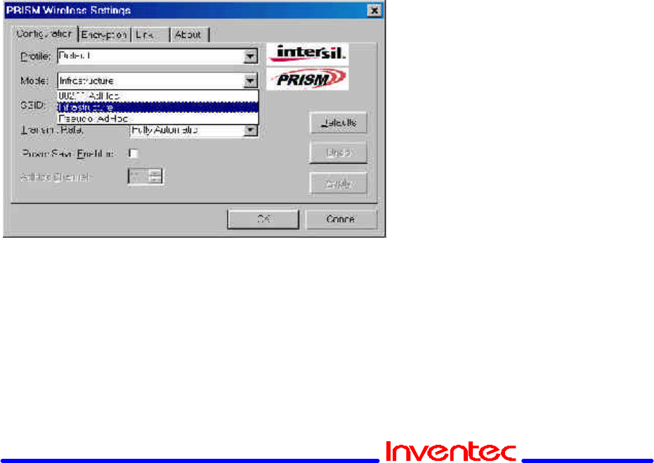
Setting the Mode
The PRISM WLAN Interface card can operate in one of three modes, which are
specified in the Mode field of the Configuration menu. Clicking the down arrow at
the right of the Mode field displays the available modes.
802.11 AdHoc Mode
IEEE 802.11, the standard on which the WLAN protocol is based, defines two
modes to handle two separate needs. The first, called AdHoc (or IBSS) mode, is
used when two or more wirelessly-enabled PCs wish to exchange data directly,
without an Access Point. In this case the PCs can establish an AdHoc network in
which they are the only members and over which they can exchange data. To

Revision: 0.1
CP-108 Wireless LAN Card User’s Manual Date:01/15/2002
Page 10 of 17
exchange data, each computer participating in the AdHoc network must also
specify the same SSID and AdHoc Channel in this menu.
Infrastructure Mode
The second mode defined by the IEEE 802.11 standard is called infrastructure
mode, and is the primary application for WLAN operation. In this mode all data on
the wireless network is directed to an Access Point, which then routes the data to
the appropriate wireless station. The Access Point may also be configured to allow
data to be bridged from the wireless network to wired networks.
To participate in a wireless LAN in infrastructure mode, every station and Access
Point must specify the same SSID. In infrastructure mode, all available channels
are scanned for traffic, so there is no need to specify a channel.
Pseudo AdHoc
A third mode has been defined by Intersil, and is used mainly for testing purposes.
Pseudo AdHoc mode allows computers to communicate even without exchanging
compatibility data. For instance, you can send broadcast frames in this mode over
a given channel and expect no interruption by beacons or other packets not
involved in the test. This mode can be used for Packet Error Rate Testing, for
example, to evaluate performance.
As with AdHoc mode, each computer participating in the Pseudo AdHoc network
must also specify the same SSID and AdHoc Channel in this menu. However, note
that this mode can only be used to communicate with other PRISM WLAN
Interface cards.
Setting the SSID
The SSID is the Service Set IDentifier used by Access Points and stations to
identify a wireless LAN. Your PRISM WLAN Interface card scans the available
channels looking for an Access Point (in infrastructure mode) or another station (in
AdHoc mode) which has specified this same SSID. It then attempts to associate
with these Access Points or stations to form a wireless LAN.
To change the SSID, simply highlight it, type the new SSID, and click the Apply
button.
In typical infrastructure applications a company will use a single SSID for all
Access Points. If the radio is scanning and cannot find a channel when an Access
Point is known to be in range, verify that the SSID is set correctly.
Revision: 0.1
CP-108 Wireless LAN Card User’s Manual Date:01/15/2002
Page 11 of 17
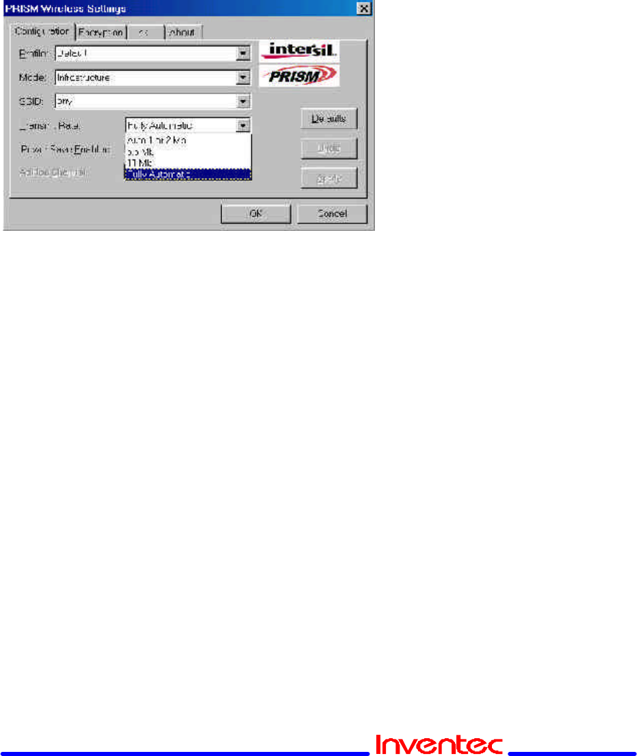
Setting the Transmit Rate
The Transmit Rate field specifies the rate at which the radio in your PRISM WLAN
Interface card transmits and receives data. You can view the available rates by
clicking the down arrow at the right of the Transmit Rate field.
The transmit rate can be set to:
?? Fully Automatic – your PRISM card chooses the highest available rate
providing reliable communications based on the capabilities of the Access
Point or station with which it communicates and on the received signal quality
?? Auto 1 or 2 Mb – allows only 1 and 2 Mb/s operation
?? 5.5 Mb – allows only 5.5 Mb/s operation
?? 11 Mb – allows only 11Mb/s operation
To change the Transmit Rate, click the down arrow at the right of the field, highlight
the rate you want to set, and click the Apply button.
Under most conditions, you should choose Fully Automatic as the transmit rate. In
general, fixed rates are used only in test environments.
Enabling Power Save Mode
The IEEE 802.11 standard provides a Power Save Mode. In this mode your PRISM
card listens for a beacon (a periodic frame which defines the network type and
attributes) and determines the beacon interval. Between beacons the card puts
itself to sleep, enabling power savings. At the time of the expected beacon the card
wakes itself up and receives the beacon. The received beacon contains
information about whether the Access Point or station has buffered frames for the
card. If frames are available the card requests those frames until no more frames
are available. The card then goes back to sleep until the next beacon.
Revision: 0.1
CP-108 Wireless LAN Card User’s Manual Date:01/15/2002
Page 12 of 17
For Access Points that support power save mode and for stations equipped with
WLAN cards, enabling this mode can significantly reduce power consumption,
which is particularly important if the host computer is operating on battery power.
However, be aware that power save mode also results in lowered transmission and
reception speed on the wireless LAN.
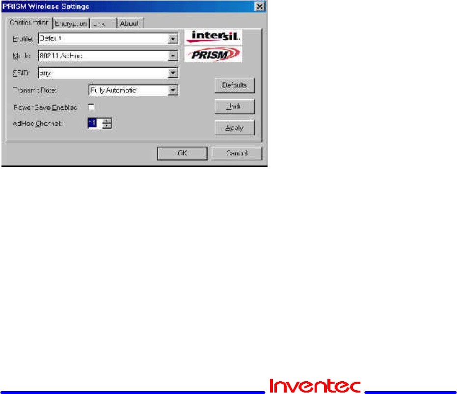
Selecting the Ad Hoc Channel
When communicating in AdHoc or Pseudo AdHoc mode, you must specify a
channel on which communications will take place. To specify a channel, click the
up or down arrow at the right of the AdHoc Channel field until the channel you want
to set appears, and then click the Apply button.
This field is greyed in infrastructure mode because the Access Point automatically
selects the channel.
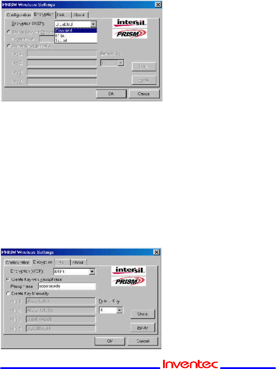
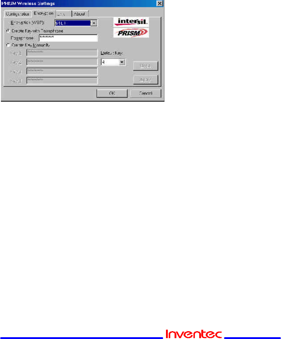
6. Encryption Menu
The Encryption menu lets you enable encryption and set the encryption keys. To
see the available encryption methods, click the down arrow at the right of the
Encryption {WEP} field.
There are two encryption methods available. The IEEE 802.11 specification
defines Wired Equivalent Privacy (WEP) using a 64-bit key. This capability was
extended by the industry to allow a 128-bit key. If you specify an encryption
method, you will only be able to communicate with Access Points and stations that
use the same encryption method and keys.
Revision: 0.1
CP-108 Wireless LAN Card User’s Manual Date:01/15/2002
Page 13 of 17
Disabling Encryption
To disable encryption, click the down arrow at the right of the Encryption field,
select Disabled, and click the Apply button.
Enabling Encryption
To enable encryption, click the down arrow at the right of the Encryption field,
select either 64 bit or 128 bit, and click the Apply button. After enabling an
encryption method, you must then specify encryption keys, as described in the
following sections.
Creating Encryption Keys Using a Passphrase
To create encryption keys using a passphrase, click the radio button next to Create
Key with Passphrase and type a character string in the Passphrase field. As you
type, the Configuration Utility uses an algorithm to generate four keys used for
encryption.
Revision: 0.1
CP-108 Wireless LAN Card User’s Manual Date:01/15/2002
Page 14 of 17
When you finish typing your character string and click the Apply button, the
Configuration Utility uses asterisks to mask both your passphrase and the keys it
generates.
Using a passphrase to generate the four keys makes it easy to set the same keys
for all members of your wireless LAN.
Creating Encryption Keys Manually
If you want, you can create encryption keys manually by clicking the radio button
next to Create Key Manually, as shown in the following illustration.
When you click this button, the cursor appears in the field for Key 1. For 64-bit
encryption, you must type exactly 10 hexadecimal digits in each of the four key
fields; for 128-bit encryption, you must type exactly 26 hexadecimal digits. You
then click the Apply button to create your encryption keys. After you click the Apply
button, the Configuration Utility uses asterisks to mask your keys.
Default Key
The Default Key field lets you specify which of the four encryption keys you use to
transmit data on your wireless LAN. You can change the default key by clicking on
the down arrow at the right of this field, selecting the number of the key you want to
use, and then clicking the Apply button. As long as the Access Point or station with
which you are communicating has the same key in the same position, you can use
any of the keys as the default.
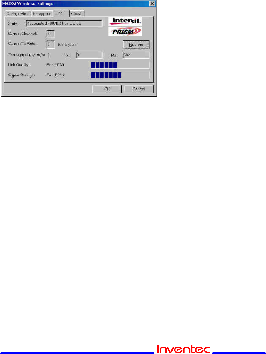
7. Link Menu
The Link menu provides information on the status of your communications with the
wireless LAN.
Revision: 0.1
CP-108 Wireless LAN Card User’s Manual Date:01/15/2002
Page 15 of 17
The fields in this menu provide the following information:
?? State: shows the association state of your computer with the wireless LAN.
The above illustration shows that your computer is associated with an Access
Point and gives the Access Point’s MAC address.
?? Current Channel: shows the channel on which the connection is made. In
Infrastructure mode, this number changes as the radio scans the available
channels.
?? Current Tx Rate: shows the highest transmit rate of the current association.
?? Throughput: shows the short term transmit and receive throughput in
bytes/second continuously updated.
?? Link Quality: is based on the quality of the received signal of the Access Point
beacon.
?? Signal Strength: is based on the received signal strength measurement of the
baseband processor of the Beacon signal.
You can click the Rescan button to force the radio to rescan all available channels.
If your link quality or signal strength is poor, rescanning can be used to push the
radio off a weak Access Point and search for a better link with another Access
Point.
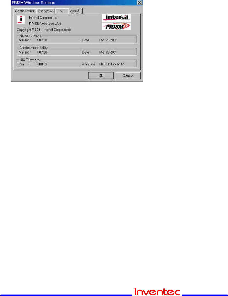
8. About Menu
The About menu provides information on the version of the Network Driver, the
Configuration Utility, and the firmware in the PRISM WLAN Interface card. In
addition, this menu also provides the MAC address of the PRISM card.
Revision: 0.1
CP-108 Wireless LAN Card User’s Manual Date:01/15/2002
Page 16 of 17
5. Federal Communication Commission Interference Statement
This equipment has been tested and found to comply with the limits for a Class B
digital device, pursuant to Part 15 of the FCC Rules. These limits are designed to
provide reasonable protection against harmful interference in a residential
installation. This equipment generates, uses and can radiate radio frequency
energy and, if not installed and used in accordance with the instructions, may
cause harmful interference to radio communications. However, there is no
guarantee that interference will not occur in a particular installation. If this
equipment does cause harmful interference to radio or television reception, which
can be determined by turning the equipment off and on, the user is encouraged to
try to correct the interference by one of the following measures:
- Reorient or relocate the receiving antenna.
- Increase the separation between the equipment and receiver.
- Connect the equipment into an outlet on a circuit different from that to which the
receiver is connected.
- Consult the dealer or an experienced radio/TV technician for help.
FCC Caution: To assure continued compliance, (example - use only shielded
interface cables when connecting to computer or peripheral devices) any changes
or modifications not expressly approved by the party responsible for compliance
could void the user's authority to operate this equipment.
This device complies with Part 15 of the FCC Rules. Operation is subject to the
following two conditions: (1) This device may not cause harmful interference, and

Revision: 0.1
CP-108 Wireless LAN Card User’s Manual Date:01/15/2002
Page 17 of 17
(2) this device must accept any interference received, including interference that
may cause undesired operation.
IMPORTANT NOTE:
FCC Radiation Exposure Statement:
This equipment complies with FCC radiation exposure limits set forth for an
uncontrolled environment. This equipment should be installed and operated with
minimum distance 20cm between the radiator & your body.
This transmitter must not be co-located or operating in conjunction with any other
antenna or transmitter.