Inventek Systems 2531F 2.4 GHz USB Dongle User Manual
Inventek Systems 2.4 GHz USB Dongle
User Manual

Inventek Systems
2 Republic Road
Billerica, MA 01862
Tel: 978-667-1962
Fax: 978-667-1949
www.Inventeksys.com
ISM2531-USB-F ZigBee Dongle
Instruction Sheet
Product Description:
Network:
_ IEEE 802.15.4- 2.4 Ghz ZigBee
Lead-Free:
_ RoHs compliant
Host Interface:
_ USB 2.0 - Full Speed Device (12 Mbps)
Operating Voltage:
_ 5 V (±5 %)
Power Consumption < 2W:
_ TX: < 100 mA (TDC)
_ RX: < 70 mA (TBC)
Antenna / radio:
_ 2.4 GHz ISM band
_ PCB antenna – folded IFA
_ Antenna peak gain: 4.35 dBi
_ Radiated (EIRP) in standard power: 0 dBm
_ Radiated (EIRP) in high power: 10 dBm
Operating Channel
_ IEEE 802.15.4 ISM Band: Channel 11 (2.405 GHz)
to channel 26 (2.480 GHz)
Physical Specification:
_ Dimensions: 38 x 19 x 9 mm (1.5 x 0.7 x 0.3 inch)
_ Operating temperature: -25 °C...85 °C (-13 °F...185 °F)
_ Storage temperature: -40 °C...85 °C (-40 °F...185 °F)
Radio certification:
_ FCC Part 15
_ ETSI EN 300 328 V1.
ISM2531-USB-F Setup Guide:
Step 1 – Set Up The Rx Settings on the ZigBee Dongle
a. Ensure the ZigBee dongle is powered and connected to your computer via the CC Debugger.
b. Hit the reset button on the debugger. It will light of green if the device is connected properly.
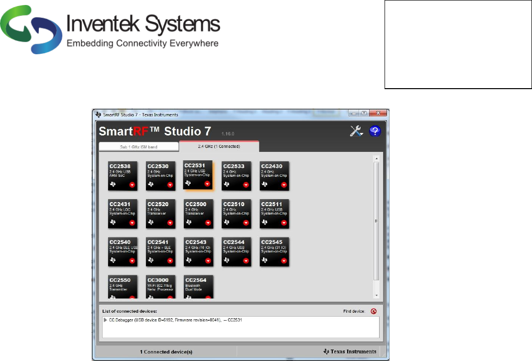
c. Open SmartRF Studio7
Inventek Systems
2 Republic Road
Billerica, MA 01862
Tel: 978-667-1962
Fax: 978-667-1949
www.Inventeksys.com
Figure 1. SmartRF Studio7
d. Click the “2.4 GHz” Tab. The Part Number of the connected device will be highlighted in
Figure 1.
e. Double Click on the “CC2531” box to open the Device Control Panel
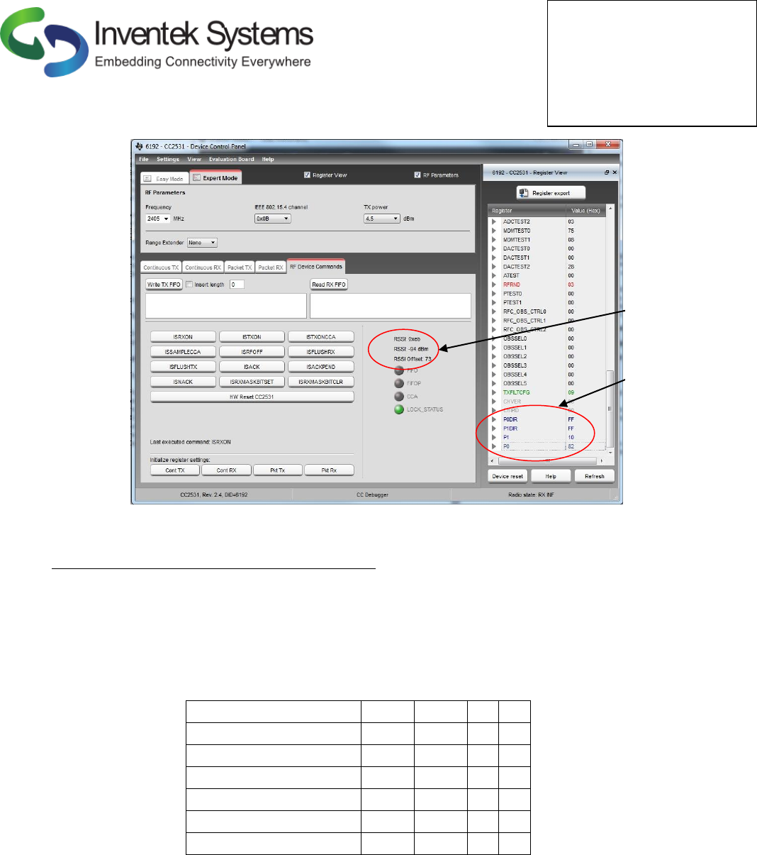
f. Make sure the box next “Register View” is checked.
g. Select the “RF Device Commands” tab
h. Click “Cont RX” to initialize register settings
i. In “Register View” set P0DIR, P1DIR, P0, and P1 to required value (see Table 1)
j. Click “ISRXON” to start receiving. See Figure 2 for image of a
k. Observe RSSI Value.
Inventek Systems
2 Republic Road
Billerica, MA 01862
Tel: 978-667-1962
Fax: 978-667-1949
www.Inventeksys.com
Figure 2. Device Control Panel in Receive Mode
Step 2 – Set Up The Tx Settings on the ZigBee Dongle
a. Repeat steps a-c from step 1, with a second ZigBee dongle, and on a second computer that is
located 10m from the Rx dongle
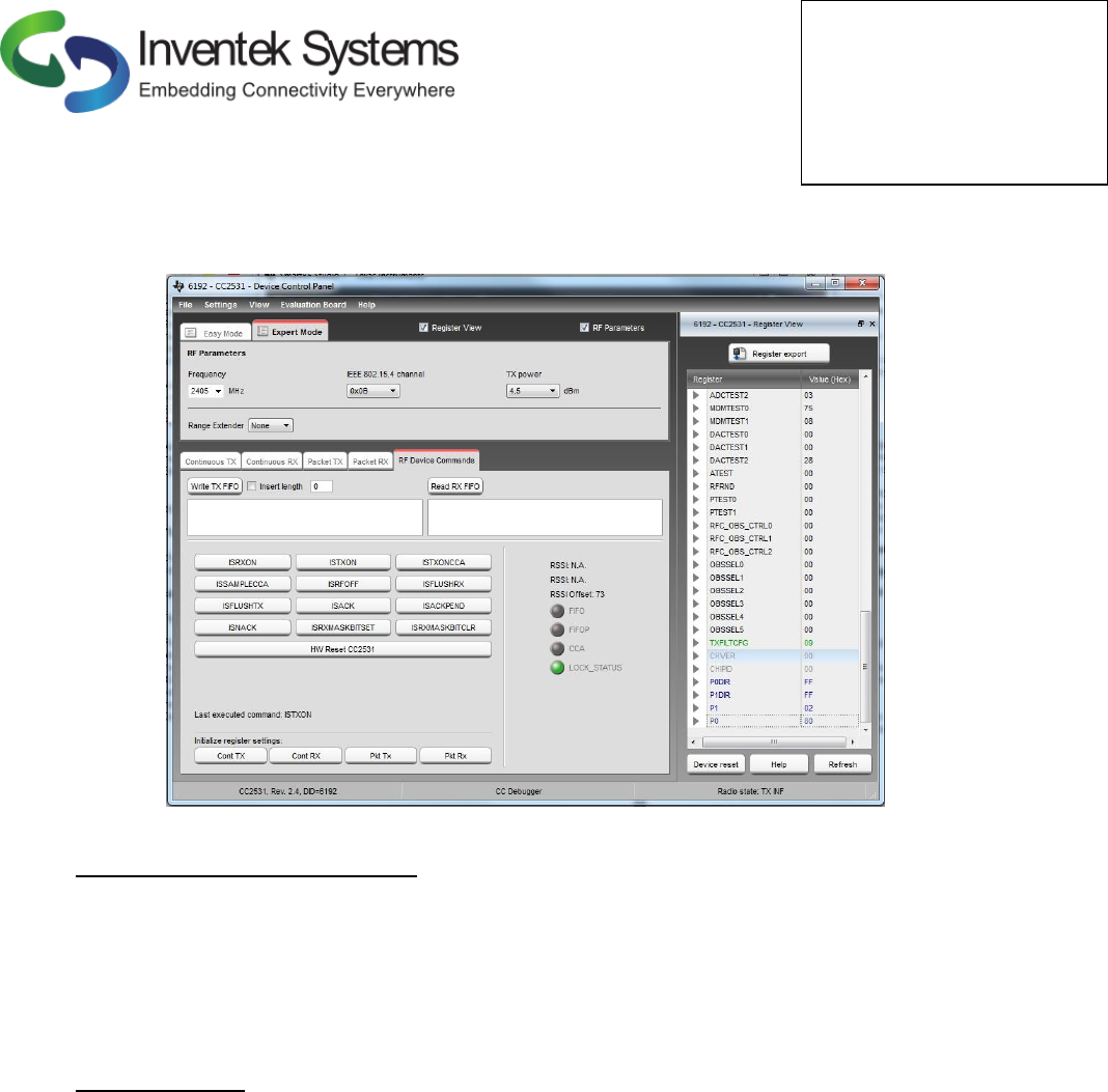
b. Select the “RF Device Commands” tab
c. Click “Cont TX” to initialize register settings
d. In “Register View” set P0DIR, P1DIR, P0, and P1 to required value (see Table 1)
e. Click “ISTXON” to start receiving
f. Observe RSSI Value from the Rx computer
Inventek Dongle Port
P0DIR
P1DIR
P0
P1
All Off
FF
FF
0
0
Rx Bypass
FF
FF
80
10
Rx High Gain
FF
FF
82
10
Rx Low Gain
FF
FF
82
0
Tx Bypass
FF
FF
80
2
Tx High Power
FF
FF
82
2
Table 1. TX and RX Register Settings for SmartRF Studio 7
Observe RSSI
Set Registers
Inventek Systems
2 Republic Road
Billerica, MA 01862
Tel: 978-667-1962
Fax: 978-667-1949
www.Inventeksys.com
Figure 3. SmartRF Studio in Tx Bypass Mode
Step 3- Observing typical RSSI Values
a. With the Rx Dongle in Rx Bypass Mode, observe the RSSI of the dongle in Tx Bypass and Tx
High Power modes.
a. At a distance of 1m a passed unit will have an RSSI of -47 dBm +/- 3 dBm for a unit
when dongle is in Tx Bypass and an RSSI of -25 dBm +/- 3 dBm when the dongle is in
Tx High Power.
b. Now you are able to successfully send and receive wirelessly via ZigBee.
Regulatory Notices
NOTE: This equipment has been tested and found to comply with the limits for a Class B digital device,
pursuant to Part 15 of the FCC Rules. These limits are designed to provide reasonable protection against
harmful interference when the equipment is operated in a residential environment. This equipment
generates, uses, and can radiate radio frequency energy and, if not installed and used in accordance with the
instruction manual, may cause harmful interference to radio communications. However, there is no
guarantee that interference will not occur in a particular installation. If this equipment does cause harmful
interference to radio or television reception, which can be determined by turning the equipment off and on,
the user is encouraged to try to correct the interference by one or more of the following measures:
a. Reorient or relocate the receiving antenna.
b. Increase the separation between the equipment and receiver.
c. Connect the equipment into an outlet on a circuit different from that to which the receiver
is connected.
d. Consult the dealer or an experienced radio/TV technician for help.
Inventek Systems
2 Republic Road
Billerica, MA 01862
Tel: 978-667-1962
Fax: 978-667-1949
www.Inventeksys.com
Operation of this device is subject to the following two conditions: (1) this device may not cause
interference, and (2) this device must accept any interference, including interference that may cause
undesired operation of this device.
L’opѐration est soumise aux deux conditions suivantes: (1) cet appareil ne peut pas provoquer
d’interfѐrences et (2) cet apparial doit accepter toute interfѐrence, y compris les interfѐrences qui peuvent
causer un mauvis fonctionment de l’appareil.
Warning: changes or modifications not expressly approved by the party responsible for compliance could
void the user’s authority to operate this equipment
The antennas used with this module must be installed to provide a separation distance of at least 20cm from
all persons, and must not be co-located or transmit simultaneously with any other antenna or transmitter,
except in accordance with FCC multi transmitter product procedures.
The ISM2531-USB-F ZigBee Dongle has been designed to operate with the following antenna and gain.
Use with other antenna types or with these antenna types at higher gains is strictly prohibited.
Manufacturer
Type of
Antenna
Model
Gain dB
Type of
Connector
Inventek
Trace Antenna
Internal
4.35
Permanent
integral
The radio transmitter has been approved by Industry Canada to operate with the antenna types listed above
with the maximum permissible gain and required antenna impedance for each antenna type indicated.
Antenna types not included in this list having a gain greater than the maximum gain indicated for that type,
are strictly prohibited for use with this device.
Cet ѐmetteur de radio a ѐtѐ approuvѐ par Industrie Canada pour fonctionner avec les types d’antennes
ѐnumѐrѐes ci-dessus avec le gain maximal admissible et impѐdance d’antenna requise pour chaque type
d’antenne indiquѐ. Types d’antennes ne figurant pas dans cette liste, ayant un gain supѐrieur au gain
maximum indiquѐ pour ce type, sont strictement interdites pour l’utilisation avec cet appareil.
Under Industry Canada regulations, this radio transmitter may only operate using an antenna of a type and
maximum (or lesser) gain approved for the transmitter by Industry Canada. To reduce potential radio
interference to other users, the antenna type and its gain should be so chosen that the equivalent
isotropically radiated power (e.i.r.p.) is not more than that necessary for successful communication.
Sous la rѐglementation d’Industrie Canada, ce transmetteur radio ne peut fonctionner en utilisant une
antenne d’un type et un maximum (ou moins) gain approuvѐes pour l’ѐmetteur par Industrie Canada. Pour
rѐduire le risqué d’interference aux autres utilisateures, le type d’antenne et son gain doivent être choisis de
maniѐre que la puissance isotrpe rayonnѐe ѐquivalente (PIRE) ne dѐpasse pas ce qui est nѐcessaire pour
une communication rѐussie.