Inventek Systems ISM4319F1 WIFI MODULE User Manual
Inventek Systems WIFI MODULE
User Manual
_____________________________________________________________________________________________
Inventek Systems - www.Inventeksys.com
2 Republic • Road Billerica, MA 01862 • Phone 978-667-1962 EVB User Manual
1
eS-WiFi Module
Evaluation Board
‘Embedded Serial-to-WiFi’
User Manual

DOC-UM-20040-1.3 EVB User Manual
_____________________________________________________________________________________________
_____________________________________________________________________________________________
Preliminary - Subject to change EVB User Manual
2
Inventek System, Inc.
User Manual Set Copyright and Company Information
Contact Information:
Telephone: +1 978-667-1962
Fax : 1 978-667-1949
Location/Mailing Address:
Inventek Systems
2 Republic Road,
Billerica, MA 01862
Hours of Operation
Monday - Friday
U.S. EST 08:00 a.m. - 05:00 p.m.
Send E-mail inquiries to:
Sales Support:
Sales@inventeksys.com
Support:
Engineering@inventeksys.com
Inventek Systems
Embedding Connectivity Everywhere!
Copyright (c)2011
At Inventek Systems we pride ourselves in being a USA-based, full service GPS and Wi-Fi company.
While GPS modules and GPS antennas has been our primary focus, we are expanding to provide a full
line of Wi-Fi products. We also provide complete GPS services from consulting to custom design,
manufacturing and training.
For more information, call 978-667-1962 or email Sales Support or Technical support
Copyright ©2011 Inventek Systems

DOC-UM-20040-1.3 EVB User Manual
_____________________________________________________________________________________________
_____________________________________________________________________________________________
Preliminary - Subject to change EVB User Manual Version 1.2
3
Evaluation Board User Manual
Table of Contents
TableofContents
1.0SCOPE..........................................................................................................................................................4
1.1SUPPORTEDPRODUCTVERSIONS4
5.6.1.24
2.0ORDERINGINFORMATION............................................................................................................................5
2.1REGULATORYCOMPLIANCE5
FCCUSERSMANUALSTATEMENTS:6
INDUSTRYCANADAUSERSMANUALSTATEMENTS:8
3.0HARDWAREINTERFACEANDMODULEOPERATION................................................................................9
3.1CONNECTORPINDETAIL11
3.2CONNECTORJ12‐EXPANSIONHEADER12
3.3CONNECTERJ11‐JTAG12
3.4CONNECTORJ8‐JTAGSELECT13
3.5CONNECTORJ5‐USBRESET(FUTURE)13
3.6CONNECTORJ7‐EXTERNALPOWER13
3.7CONNECTORJ9‐USB(VIRTUALSERIALPORT(VSP)/JTAG/POWER)13
3.8CONNECTORJ10(FUTURE)13
4.0POWERSUPPLY...........................................................................................................................................14
4.1RS‐232SERIALCOMMUNICATION14
4.2FLOWCONTROL14
4.3SUPPORTEDBAUDRATES14
4.4DEFAULTSERIALCONFIGURATION14
5.0GETTINGSTARTED................................................................................................................................15
6.0EVBTOPLEVELSCHEMATIC(PAGE1OF2)...................................................................................................18
6.1EVBTOPLEVELSCHEMATIC(PAGE2OF2)19
6.2USBTOUART20
6.3CONNECTINGMICROCONTROLLERTOES‐WIFIUART21
6.4JTAGANDRESETCONNECTIONS22
6.5ES‐WIFIPROGRAMMINGOPTIONS23
6.6ES‐WIFIUSBDIRECTCONNECTIONOPTION23
6.7ES‐WIFITESTPOINTSANDSENSORINPUTS24
DOC-UM-20040-1.3 EVB User Manual
_____________________________________________________________________________________________
_____________________________________________________________________________________________
Preliminary - Subject to change EVB User Manual
4
1.0Scope
The scope of this document is to introduce users to Inventek Systems’ evaluation board for the
family of eS-WiFi Module products, and to explain how to take use the platform.
The es-Wifi evaluation board is designed as a complete development platform of the Inventek es-
WiFi serial to Wi-Fi modules. The input to the modules can be UART, SPI or USB, however this
document focus only on the UART interface. The evaluation board is designed for the 44 pin LGA
module with a variety of Cortex M3 microcontrollers (See Section 1.2), with integrated etch
antenna, ceramic antenna or external antenna. All three antenna configurations have passed FCC
and CE testing.
1.1 Supported Product
Versions
2
This document covers the following currently available eS-WiFi modules:
ISM4319-M3-L44-C (Ceramic Antenna w/ STM32F103)
ISM4319-M3-L44-E (Printed Micro-strip Antenna w/ (STM32F103)
ISM4319-M3-L44-U (U.FL Connector to external antenna w/ (STM32F103)
ISM4319-M3E-L44-E (Printed Micro-strip Antenna w/ STM32F205RE)
ISM4319-M3G-L44-E (Printed Micro-strip Antenna w/ STM32F205RG)
DOC-UM-20040-1.3 EVB User Manual
_____________________________________________________________________________________________
_____________________________________________________________________________________________
Preliminary - Subject to change EVB User Manual Version 1.2
5
2.0OrderingInformation
Device Description Ordering Number
ISM4319-M3-EVB-E ISM4319-M3-L44-E (etched antenna w/ Cortex
M3 STMF103- 512K flash)
ISM4319-M3-EVB-E
ISM4319-M3-EVB-U/C ISM4319-M3-L44-E (U.fl connector & Ceramic
antenna w/ Cortex M3 STMF103- 512K flash)
ISM4319-M3-EVB-UC
ISM4319-M3G-EVB-E ISM4319-M3-L44-E (etched antenna w/ Cortex
M3 STMF205- 1M flash)
ISM4319-M3G-EVB-E
2.1 Regulatory Compliance
IC CE
Regulator Device ID
FCC O7P-ISM4319F1
IC 10147A-ISM4319F1
CE Compliant
RoHS Compliant
The ISM4319F1 is the Inventek part number for the Broadcom BCM4319 Wi-Fi radio SIP.

DOC-UM-20040-1.3 EVB User Manual
_____________________________________________________________________________________________
_____________________________________________________________________________________________
Preliminary - Subject to change EVB User Manual
6
FCCCertificationRequirementsandStatements:
OEM INSTRUCTIONS:
Installation: This module is limited to OEM installation only.
OEM integrators must ensure that the end-user has no manual instructions to remove or install the
module.. OEM’s must comply with FCC marking regulation part 15 declaration of conformity (Section
2.925(e)).
This module is to be installed only in mobile or fixed applications ( Please refer to FCC CFR 47 Part
2.1091(b) for a definition of mobile and fixed devices).
Separate approval is required for all other operating configurations, including portable configurations with
respect to FCC CFR 47 Part 2.1093, and different antenna configurations.
The antenna used with this module must be installed to provide a separation distance of at least 20cm
from all persons, and must not transmit simultaneously with any other antenna or transmitter, except in
accordance with FCC multi transmitter product procedures.
The ISM4319 Module has been designed to operate with the following antennas and gains. Use with
other antenna types or with these antenna types at higher gains is strictly prohibited.
Manufacturer Type of
Antenna Model Gain dB Type of
Connector
Inventek U.Fl port
Antenna
W24-SSMA-M 2.15 Unique
Connector
Pulse
Technology
Surface Mount W3043 1.85 (4 dBic) Permanent
integral
Inventek Trace Antenna NA 0 Permanent
integral
DOC-UM-20040-1.3 EVB User Manual
_____________________________________________________________________________________________
_____________________________________________________________________________________________
Preliminary - Subject to change EVB User Manual Version 1.2
7
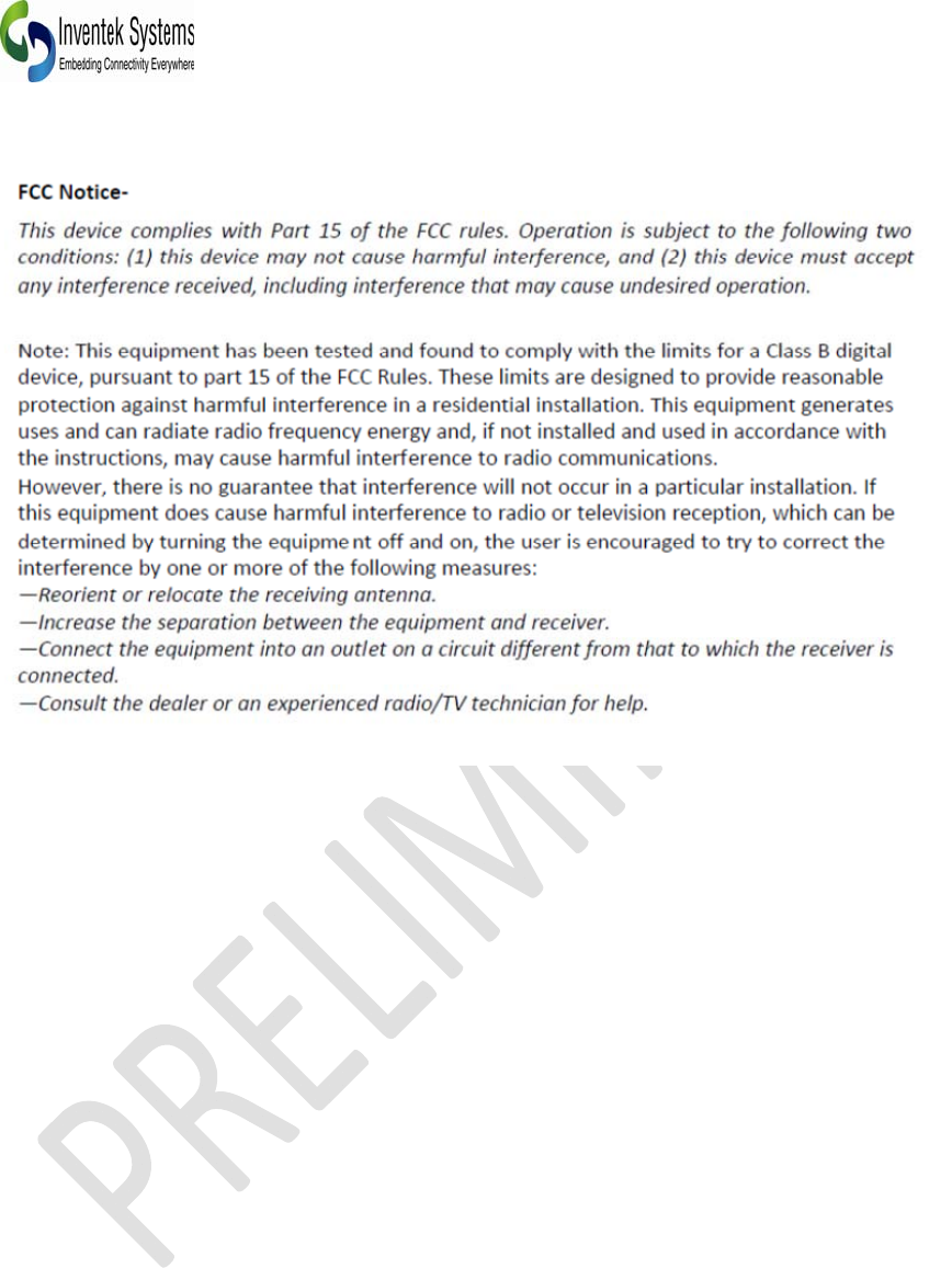
The Following FCC Information must be included in the end-user’s operating manual:
Warning: Changes or modifications to this equipment not expressly approved by manufacturer
could void the user’s ability to operate the equipment.
A clearly visible label is required on the outside of the user’s (OEM) enclosure stat the following
text:
Contains FCC ID: O7P-ISM4319F1
Contains IC: 10147A-ISM4319F1
This transmitter module has been certified for FCC Part 15 operation; when installed in a host
device, the host manufacturer is responsible for making sure that the host device with the
transmitter installed continues to be compliant with Part 15B unintentional radiator requirements.

DOC-UM-20040-1.3 EVB User Manual
_____________________________________________________________________________________________
_____________________________________________________________________________________________
Preliminary - Subject to change EVB User Manual
8
Industry Canada User’s Manual Statements:
IC RSS-210/RSS-Gen Notices:
Operation is subject to the following two conditions: (1) this device may not cause interference, and (2)
this device must accept any interference, including interference that may cause undesired operation of
the device.
Le operation est soumie aux deux conditions suivantes: (1) cet appareil ne peut pas provoquer
d’interferences et (2) cet appareil doit accepter toute interference, y compri le interferences qui peuvent
causer un mauvais foncionnament l’appareil.
Under Industry Canada Regulations, this radio transmitter may only operate using an antenna of a type
and maximum (or lesser) gain approved for the transmitter by Industry Canada. To reduce potential radio
interference to other users, the antenna typ and it’s gain should be so chosen that the equivalent
isotropically radiated power (eirp) is not more than necessary for successful communication. Antenna
types not included in the list above, having a gain greater than the maximum gain indicated for that type,
are strictly prohibited for use with this device
Sous la reglementaton d’Industrie Canada, ce transmetteur radio ne peut fonctionner in utilisant une
antenne d’un type et un maximum (ou moins) gain approuvees pour l’emetteur par Industrie Canada.
Pour reduire le risqué d’interference aux autres utilisateurs, le type d’antenne et son gain doivent etre
choisis de maniere que la puissance isotrope rayonnee equivalente (PIRE) ne depasse pas ce qui est
necessaire pour une communication reussie. Types d'antennes ne figurent pas dans la liste ci-dessus,
ayant un gain supérieur au gain maximum indiqué pour ce type, sont strictement interdites pour une
utilisation avec cet appareil.

DOC-UM-20040-1.3 EVB User Manual
_____________________________________________________________________________________________
_____________________________________________________________________________________________
Preliminary - Subject to change EVB User Manual Version 1.2
9
1.4. Complimentary Documentation
¾ ISM4319-M3-EVB Evaluation Board Specification
¾ AT Command set
¾ Es-WiFi Demo software (includes EVB Drivers)
¾ EVB Users Guide
¾ Quick Start Guide
¾ OrCAD Schematic Symbol
¾ PADS Land Pattern
¾ ISM4319 specification and Product Brief
¾ FCC Test Report
¾ NDA/ SLA documents
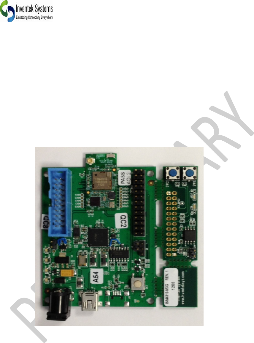
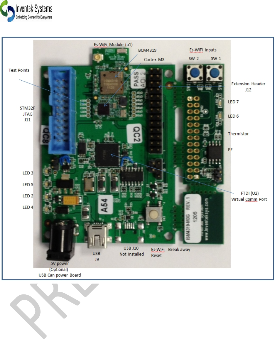
3.0 HardwareInterfaceandModuleOperation
The eS-WiFi module supports RS-232 Serial Communications Universal Serial Bus (USB), and
Serial Peripheral Interface Bus (SPI). A Micro-Controller or System Host can easily interface up to
the eS-WiFi module using one of the support hardware interfaces.
The eS-WiFi module has two modes of operation: Human Readable Mode and Machine Readable
Mode.
DOC-UM-20040-1.3 EVB User Manual
_____________________________________________________________________________________________
_____________________________________________________________________________________________
Preliminary - Subject to change EVB User Manual
10
DOC-UM-20040-1.3 EVB User Manual
_____________________________________________________________________________________________
_____________________________________________________________________________________________
Preliminary - Subject to change EVB User Manual Version 1.2
11
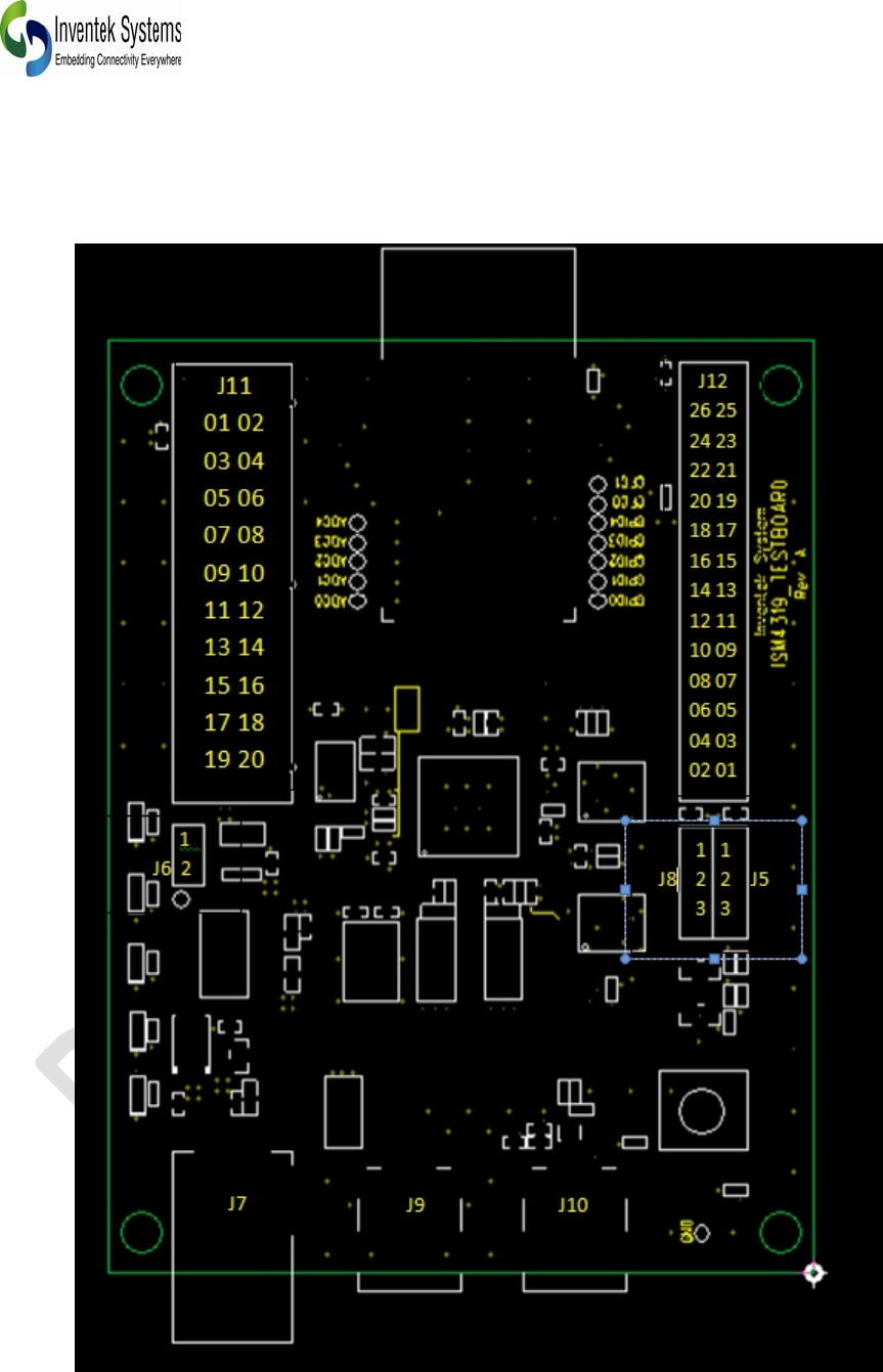
3.1 Connector Pin Detail

DOC-UM-20040-1.3 EVB User Manual
_____________________________________________________________________________________________
_____________________________________________________________________________________________
Preliminary - Subject to change EVB User Manual
12
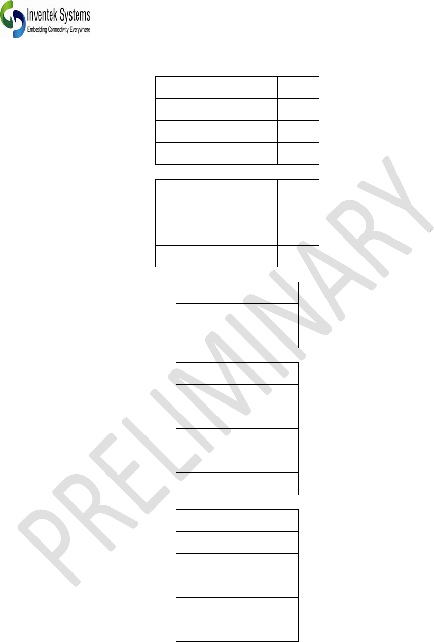
3.2 Connector J12 - Expansion Header
SignalPin Pin Signal
+3.3V26 25 GND
CFG124 23 GND
CFG022 21 GPIO2
GPIO420 19 GPIO1
GPIO318 17 GPIO0
SPI_SS_L16 15 SPI_SCK
SPI_MISO14 13 SPI_MOSI
UART_RX12 11 UART_TX
HEADER_SRST_L 10 09 WAKE_UP
GND08 07 ADC4
ADC306 05 ADC2
ADC104 03 ADC0
GND 02 01 +3.3V
3.3 Connecter J11 - JTAG
SignalPin Pin Signal
+3.3V01 02 NC
JLINK_TRST_L 03 04 GND
JLINK_TDI 05 06 GND
JLINK_TMS 07 08 GND
JLINK_TCK 09 10 GND
GND11 12 GND
JLINK_TDO 13 14 GND
JLINK_RESET 15 16 GND
NC17 18 GND
NC19 20 GND
DOC-UM-20040-1.3 EVB User Manual
_____________________________________________________________________________________________
_____________________________________________________________________________________________
Preliminary - Subject to change EVB User Manual Version 1.2
13
3.4 Connector J8 - JTAG Select
Signal Pin Function
+3.3V 01 ViaJ9
JLINK_SELECT 02 Common
GND 03 UseJ3
3.5 Connector J5 - USB Reset (Future)
Signal Pin Function
GPIO4 01 Enabled
USBRESET 02 Common
GND 03 Disabled
3.6 Connector J7 - External Power
Signal Pin
+5.0V Center
GNDShield
3.7 Connector J9 - USB (Virtual Serial Port(VSP)/JTAG/Power)
Signal Pin
USB_5V 01
D‐02
D+ 03
NC 04
GND 05
3.8 Connector J10 (Future)
Signal Pin
USB_5V 01
D‐02
D+ 03
NC 04
GND 05

DOC-UM-20040-1.3 EVB User Manual
_____________________________________________________________________________________________
_____________________________________________________________________________________________
Preliminary - Subject to change EVB User Manual
14
4.0 Power Supply
The es-WiFi evaluation board can be powered by either USB (Power) or external 5 V DC power
adapters. It is recommended that you do not use both USB and external power, select one.
4.1 RS-232 Serial Communication
When the eS-WiFi module is interfaced serially, the serial interface needs to be configured for :
8 bit data, no parity, and one stop bit -- (8-n-1).
4.2 Flow Control
The eS-WiFi module doesn’t require or support Flow Control, so Flow Control should be ‘None’
4.3 Supported Baud Rates
The eS-WiFi module support the following serial baud rates:
1200
2400
4800
9600
19200
38400
57600
115200
230400
460800
921600
4.4 Default Serial Configuration
The eS-WiFi module is shipped with the default serial configuration of 115200 baud, 8 data bits, no
party, and 1 stop bits.
DOC-UM-20040-1.3 EVB User Manual
_____________________________________________________________________________________________
_____________________________________________________________________________________________
Preliminary - Subject to change EVB User Manual Version 1.2
15
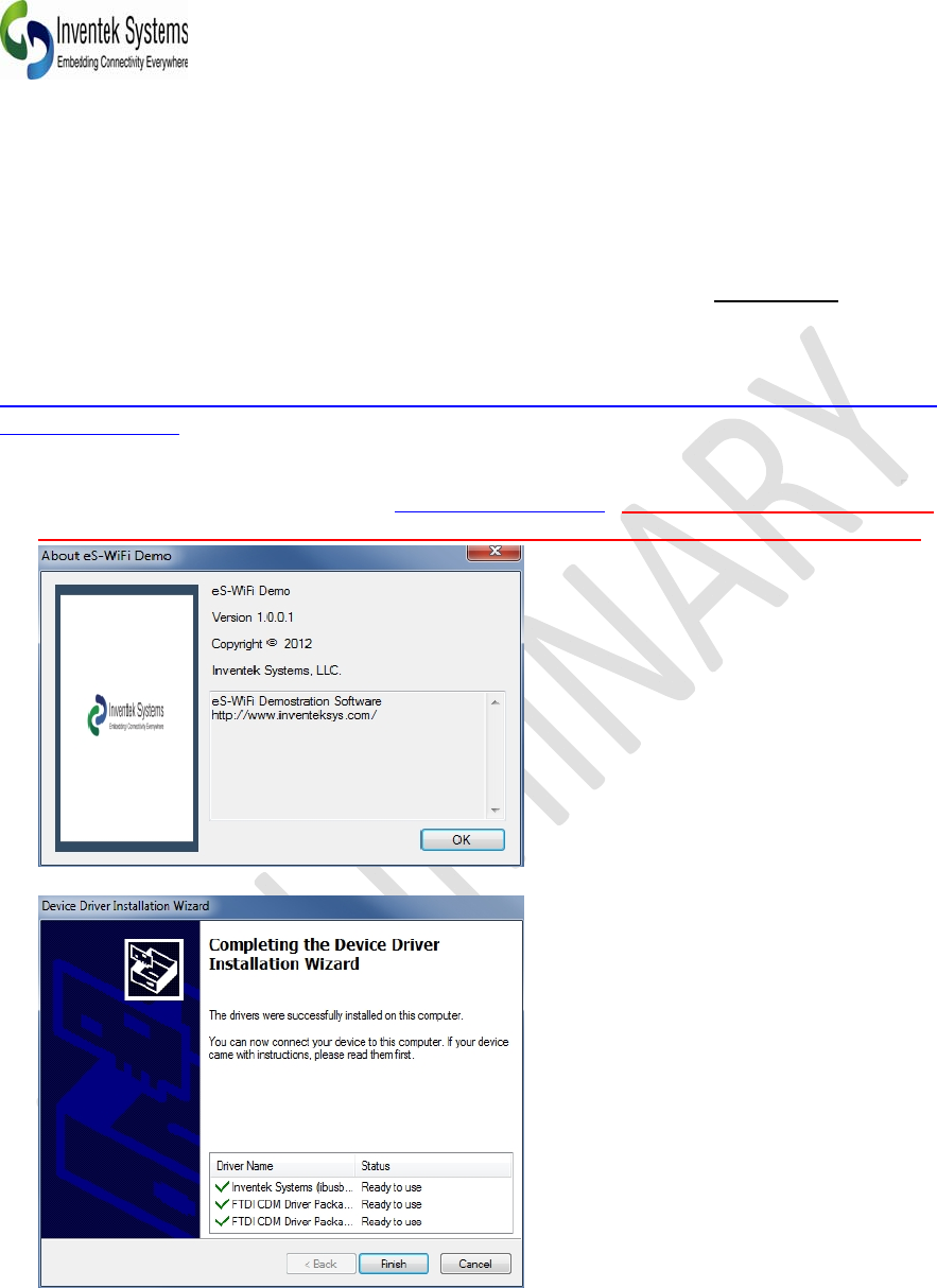
5.0 Getting Started
5.1 Start the eS-WiFi Demo Software. This can be downloaded from the Inventek Systems web page or
CD and contact sales for the password. Download the file, unzip and run as Administrator. The software
will create an Inventek Systems folder under Program Files on a Windows 32 bit and Program Files (x86)
folder on Windows 64 bit.
http://www.inventeksys.com/products-page/wifi-eval-kits/ism4319-m3-l44-e-embedded-serial-to-wifi-
module-duplicate/.
5.2 The Demo software package will create a folder on your PC, called Inventek Please visit the website
for updated documents and software, www.Inventeksys.com. Use the Inventek “ es-WiFi Help
document” for running the evaluation board along with the “AT Command Set document”.
5.3 Install Drivers
Check website for latest version of software
DOC-UM-20040-1.3 EVB User Manual
_____________________________________________________________________________________________
_____________________________________________________________________________________________
Preliminary - Subject to change EVB User Manual
16
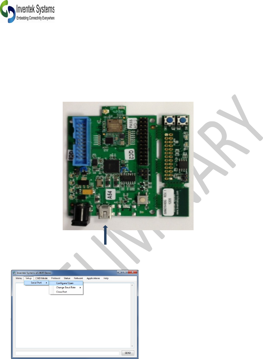
5.4 Connect the ISM4319-M3-EVB board to a USB port on your computer. Once the Install device driver
software message have completed the EVB is ready for use.
Now that the drivers have been installed on your PC, plug the USB cable into USB (J9) located next to
the power jack. You do not need DC power to run the evaluation. Power is provided by the USB port.
5.5 Connect to the board by selecting Setup > Serial Port > Configure/Open.
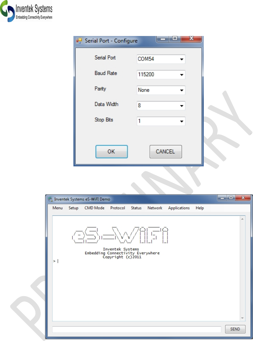
You will now configure the VSP (Virtual Serial Port) connection the EVB. You will need to determine what
COM port is attached to the EVB. This can be done by using Windows Device Manager. In this case,
COM54 is the port connected to the EVB.
The default setting for the EVB is 115200, None, 8, 1.
DOC-UM-20040-1.3 EVB User Manual
_____________________________________________________________________________________________
_____________________________________________________________________________________________
Preliminary - Subject to change EVB User Manual Version 1.2
17
Click the OK button and press the Reset button on the EVB (SW2). You will now the
the reset banner.
The eS-WiFi module is shipped with the default serial configuration of 115200 baud, 8 data bits, no
party, and 1 stop bits.
DOC-UM-20040-1.3 EVB User Manual
_____________________________________________________________________________________________
_____________________________________________________________________________________________
Preliminary - Subject to change EVB User Manual
18
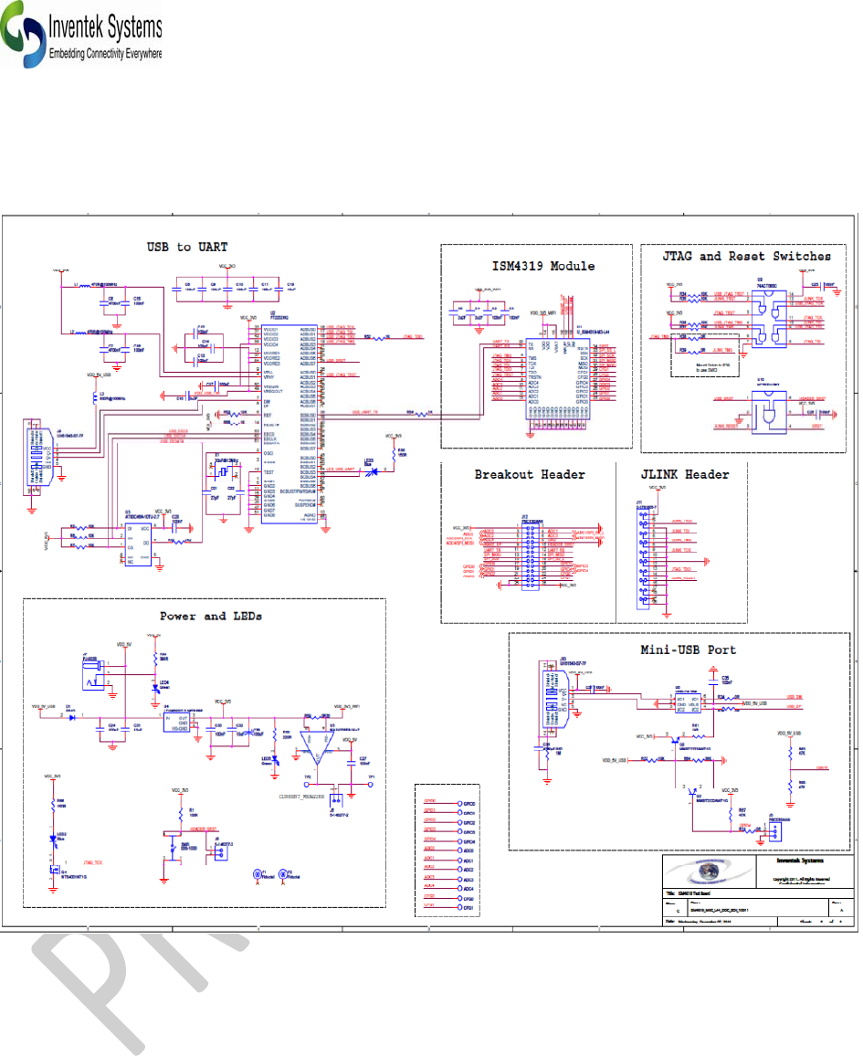
6.0 EVB Top Level Schematic (Page 1 of 2)
Note: Second USB port J10 is not installed on the evaluation boards. Please contact Inventek if you
want to use USB or SPI mode.
Typical application circuits please refer to schematic below. For a *.pdf version please visit the Wi-Fi
evaluation board website, www.Inventeksys.com.
DOC-UM-20040-1.3 EVB User Manual
_____________________________________________________________________________________________
_____________________________________________________________________________________________
Preliminary - Subject to change EVB User Manual Version 1.2
19
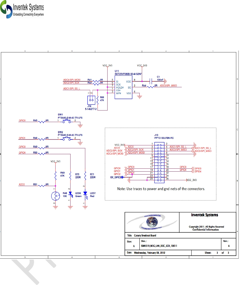
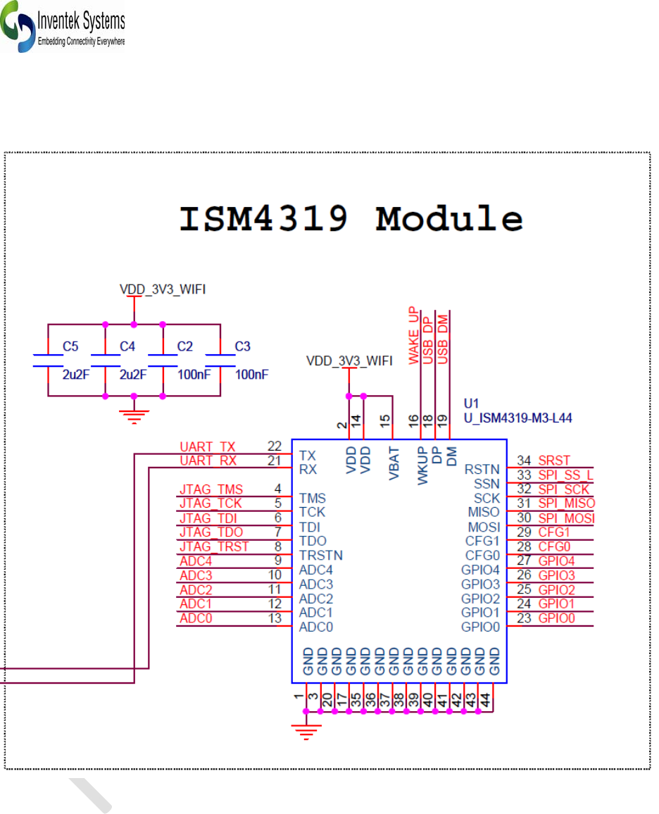
6.1 EVB Top Level Schematic (Page 2 of 2)
DOC-UM-20040-1.3 EVB User Manual
_____________________________________________________________________________________________
_____________________________________________________________________________________________
Preliminary - Subject to change EVB User Manual
20
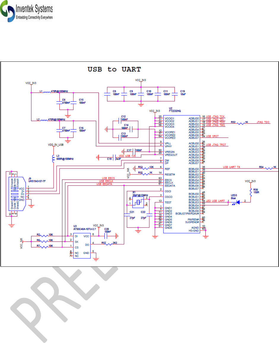
6.2 USB to UART
DOC-UM-20040-1.3 EVB User Manual
_____________________________________________________________________________________________
_____________________________________________________________________________________________
Preliminary - Subject to change EVB User Manual Version 1.2
21
6.3 Connecting Microcontroller to eS-WiFi UART
DOC-UM-20040-1.3 EVB User Manual
_____________________________________________________________________________________________
_____________________________________________________________________________________________
Preliminary - Subject to change EVB User Manual
22
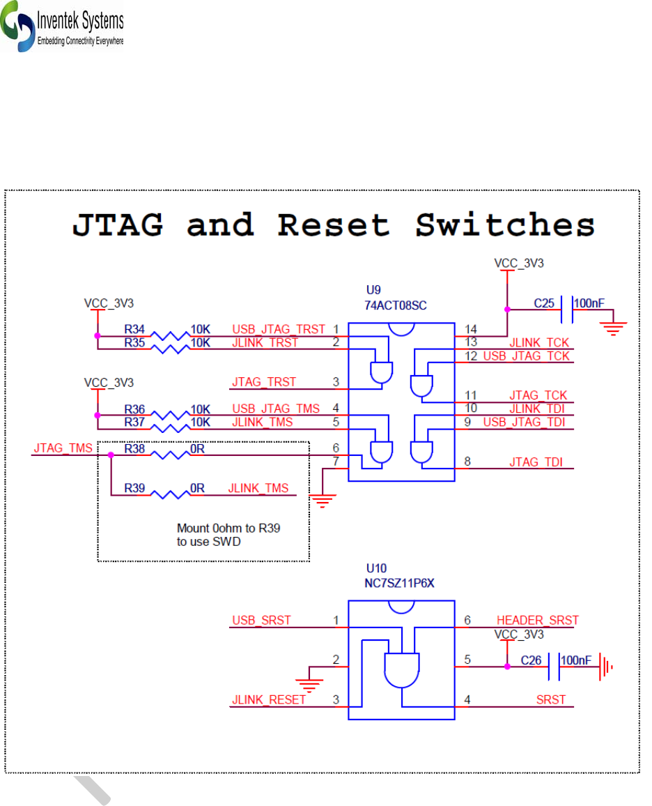
6.4 JTAG and Reset Connections
DOC-UM-20040-1.3 EVB User Manual
_____________________________________________________________________________________________
_____________________________________________________________________________________________
Preliminary - Subject to change EVB User Manual Version 1.2
23
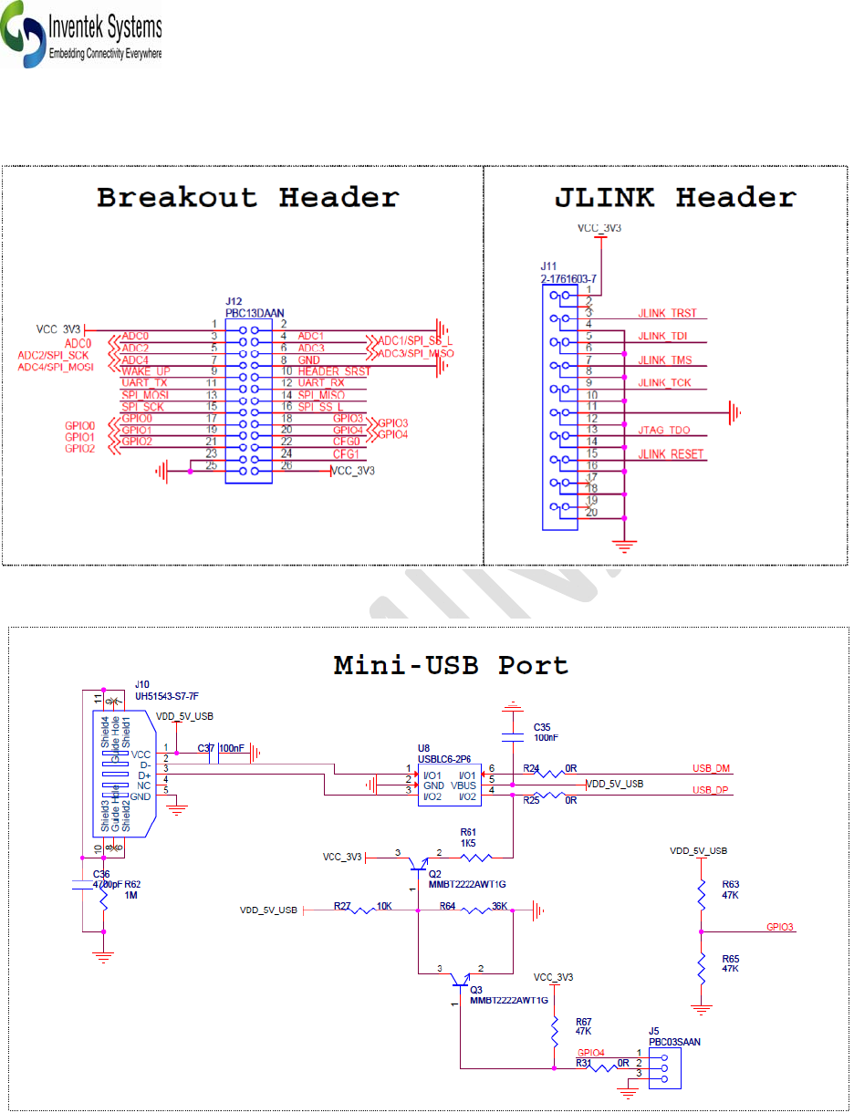
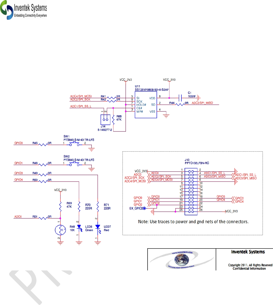
6.5 eS-WiFi Programming Options
6.6 eS-WiFi USB Direct Connection Option
(Contact Inventek for this mode)
Note: Second USB port J10 is not installed. This is a direct USB connection to the es-WiFi module. This
evaluation board is for UART only. Contact Inventek is you are interested in USB
DOC-UM-20040-1.3 EVB User Manual
_____________________________________________________________________________________________
_____________________________________________________________________________________________
Preliminary - Subject to change EVB User Manual
24
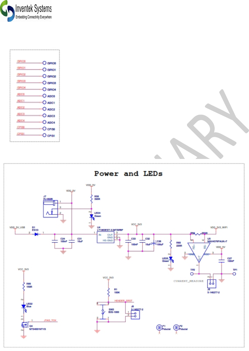
6.7 eS-WiFi Test points and Sensor Inputs
(
Errata: Current measurements are not supported with the EVB. U5 pins 4 and 5 are reversed on the PCB.
So you cannot take current measurements as delivered. Inventek will fix this on our future EVB builds.
DOC-UM-20040-1.3 EVB User Manual
_____________________________________________________________________________________________
_____________________________________________________________________________________________
Preliminary - Subject to change EVB User Manual Version 1.2
25

DOC-UM-20040-1.3 EVB User Manual
_____________________________________________________________________________________________
_____________________________________________________________________________________________
Preliminary - Subject to change EVB User Manual
26
Document Revision History
Date Name Description Revision File Name
1/02/11 MFT Initial Creation 1.0 User Manual Initial Release
3/27/11 MFT Added FCC IC and Canada 1.1 Update
5/7/2011 MFT ERRATTA 1.2 Current measurement bug

DOC-UM-20040-1.3 EVB User Manual
_____________________________________________________________________________________________
_____________________________________________________________________________________________
Preliminary - Subject to change EVB User Manual Version 1.2
27
Inventek Systems
2 Republic Road
Billerica, MA 01862
www.inventeksys.com