Invention Planet PR-1003 Smart Display User Manual
Invention Planet, LLC Smart Display Users Manual
Users Manual
Smart Display
USER MANUAL & GUIDE
www.PocketRadar.com
SD2010
For use with Pro Radar Module (model RM1510)
or with Smart Coach radar (model SR1100)

Pocket Radar, Inc.
3535 Industrial Dr. Suite A4
Santa Rosa, CA 95403
Toll Free: 888-381-2672
Support: Info@PocketRadar.com
Website: www.PocketRadar.com
Preliminary

TABLE OF CONTENTS
Introduction...................................................................................1
What’s Included (Display).............................................................2
Product Tour.................................................................................3
Smart Display..........................................(3)
Accessories.............................................................................4 - 5
Included...................................................(4)
Not Included............................................(5)
Mounting Options..........................................................................6
Select Your Radar.........................................................................7
Pro Radar Module....................................(7)
Smart Coach radar...................................(7)
Pro Radar Module.................................................(Pages 8 - 28)
Getting Started........................................................................8 - 9
Set Up Instructions...................................(8)
Set Up Illustrations...................................(9)
Pairing.........................................................................................10
Aiming.................................................................................11 - 12
Must Aim Radar at Release Point.............(11)
Aiming Illustrations....................................(12)
Separate Accessories.................................................................13
Mounting Options........................................................................14
Power Options............................................................................15
Power On - Self Test.................................(15)
Standard Batteries....................................(15)
USB Powered...........................................(15)
Standard Menu...................................................................16 - 18
Recall Memory..........................................(16)
Clear Memory ..........................................(17)
USB / Battery Level..................................(18)

TABLE OF CONTENTS
Advanced Menu..................................................................19 - 25
Measurement Units (vnt)..........................(20)
Sensitivity / Range (sen)...........................(21)
Auto-Off / Timer (tof)...............................(22)
Auto-On (aon)...........................................(23)
Brightness (br).........................................(24)
Display Version (Uer)...............................(25)
Sensitivity Settings......................................................................26
Factory Default Settings.............................................................27
Specications.............................................................................28
Smart Coach radar..............................................(Pages 29 - 46)
Getting Started....................................................................29 - 30
Set Up Instructions...................................(29)
Set Up Illustrations...................................(30)
Pairing.........................................................................................31
Aiming.................................................................................32 - 33
Must Aim Radar at Release Point.............(32)
Aiming Illustrations....................................(33)
Separate Accessories.................................................................34
Mounting Options........................................................................35
Power Options............................................................................36
Power On - Self Test.................................(36)
Standard Batteries....................................(36)
USB Powered...........................................(36)
Standard Menu...................................................................37 - 38
Recall Memory..........................................(37)
USB / Battery Level..................................(38)

TABLE OF CONTENTS
Advanced Menu..................................................................39 - 44
Measurement Units (vnt).........................(40)
Auto-Off / Timer (tof)...............................(41)
Auto-On (aon)...........................................(42)
Brightness (br).........................................(43)
Display Version (Uer)...............................(44)
Factory Default Settings.............................................................45
Specications.............................................................................46
Troubleshooting..................................................................47 - 50
Interference.............................................(47)
Ghost Readings......................................(48)
Tips to Eliminate Interference.................(48)
Angles.....................................................(49)
Cosine Error............................................(50)
Error Codes................................................................................51
FCC Class B Statement..............................................................52
Product Label..........................................(52)
User Manual............................................(52)
Warranty Information...........................................................53 - 54

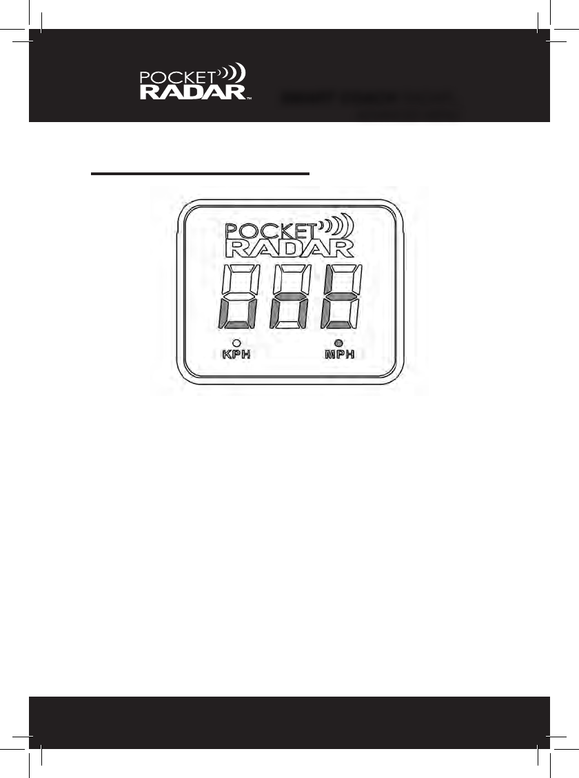
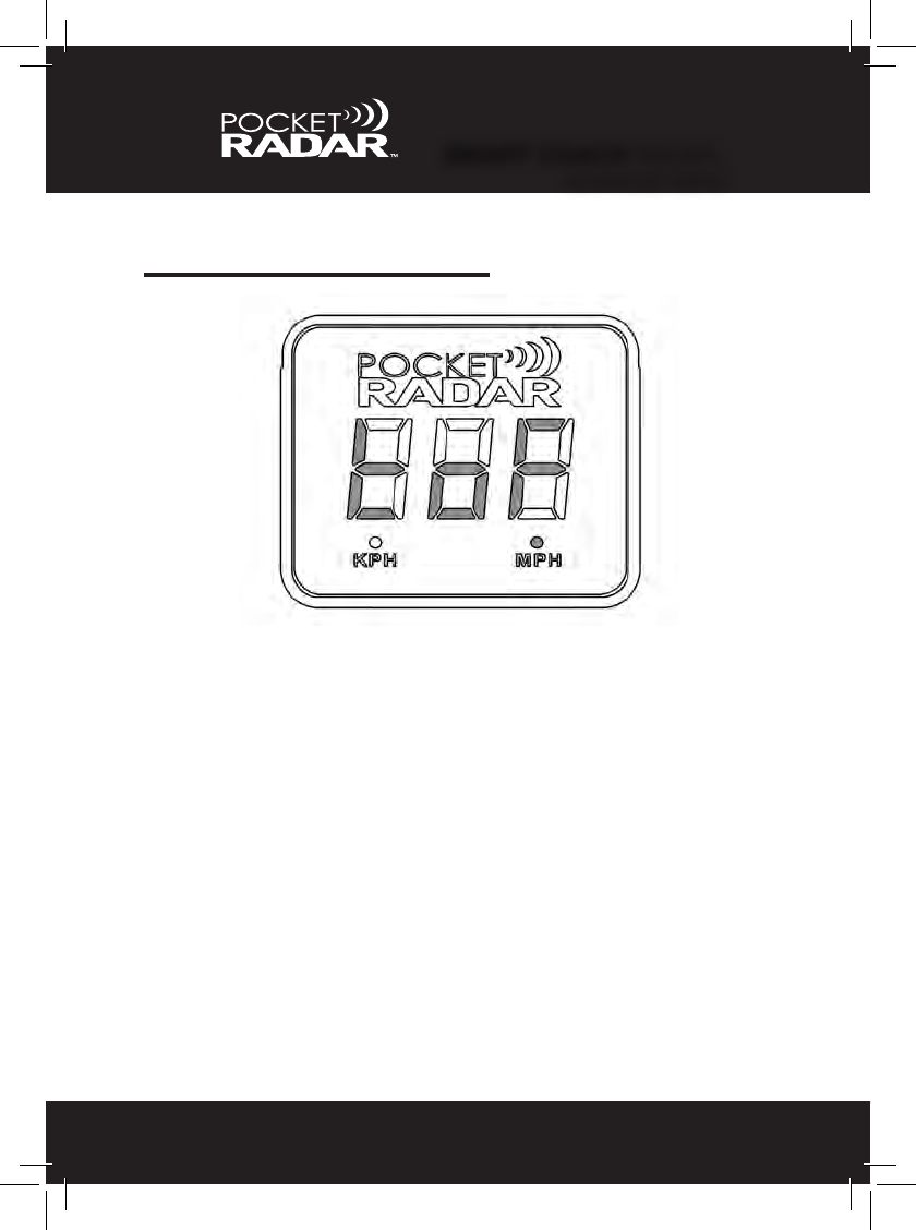
Congratulations! You are now the owner of the most exible, pro
performance speed display on the market. Innovative technology places
the Pocket Radar’s Smart product line at the forefront of the sports and
analytics revolution by providing accurate and instant feedback.
The Smart Display is compatible with multiple Pocket Radar devices,
including the Smart Coach radar and the Pro Radar Module. The
Smart Display is viewable to over 100 feet in bright sunlight, with a wide
viewing angle and full 3 digit display. Lightweight and ultra-portable for
indoor or on the eld use, its brightness levels adjust automatically with
lighting conditions. It can be powered using standard Alkaline C-size
batteries or externally using standard USB chargers or Power Packs.
The Pro Radar Module features proprietary ball-tracking technology to
provide the user with professional level accuracy of +/- 1 MPH. The
rugged, water-resistant casing is built from the same high-impact plastic
as football helmets. Flexible conguration features allow for customized
set-up options to best t your speed measurement needs.
The Smart Coach radar is a one of a kind speed radar that can display
speeds stand-alone, connected to the Smart Display, or connected to
the Pocket Radar App. With professional level accuracy of +/- 1 MPH, it
features the same proprietary ball-tracking technology as the Pro Radar
Module, but in a pocket-sized form factor.
If you want to be a power user and try other features and settings,
reading through this manual will help you to take full advantage of the
other features and capabilities of Pocket Radar’s Smart product line.
Any questions: check the Pocket Radar™ website under frequently
asked questions (FAQ’s) or contact us at Info@PocketRadar.com.
INTRODUCTION
1
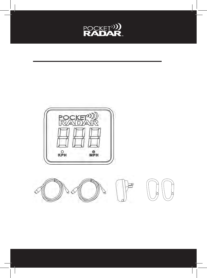
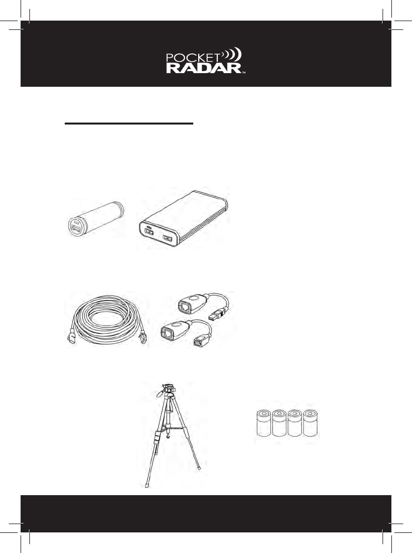
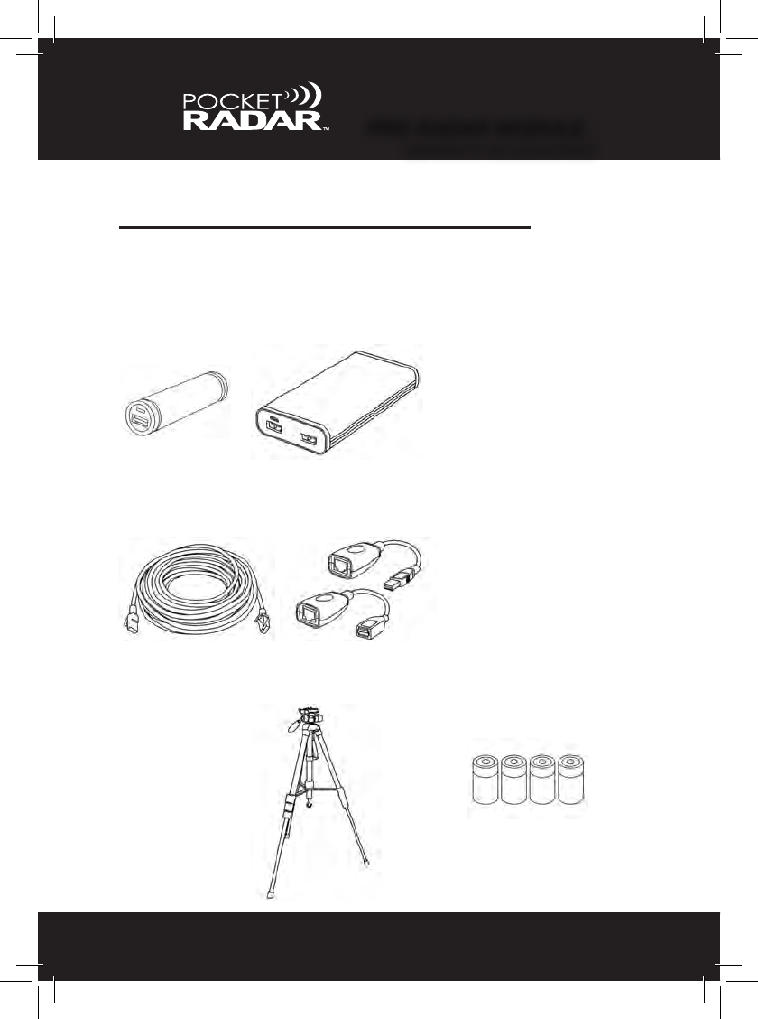
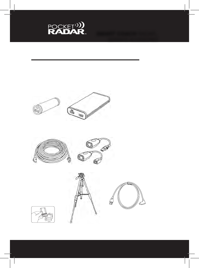
WHAT’S INCLUDED (DISPLAY)
2
2. One 2 amp AC power supply (USB charger)
1. Two 6 ft (2 meter) USB cables Type A to Micro B
3. Two carabiners
The parts included with your Smart Display package are listed below.
See page 7 for Radar selection.
If you are missing any components, please contact Pocket Radar, Inc.
at 1-888-381-2672 or email Info@PocketRadar.com
1 2 3
Smart Display
SD2000
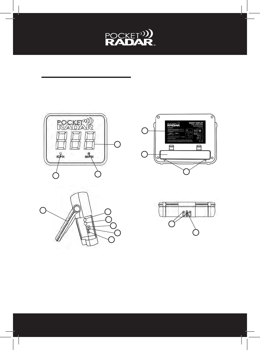
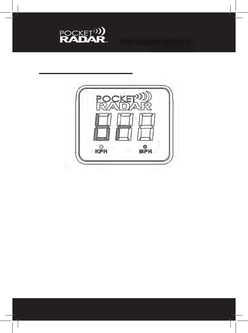
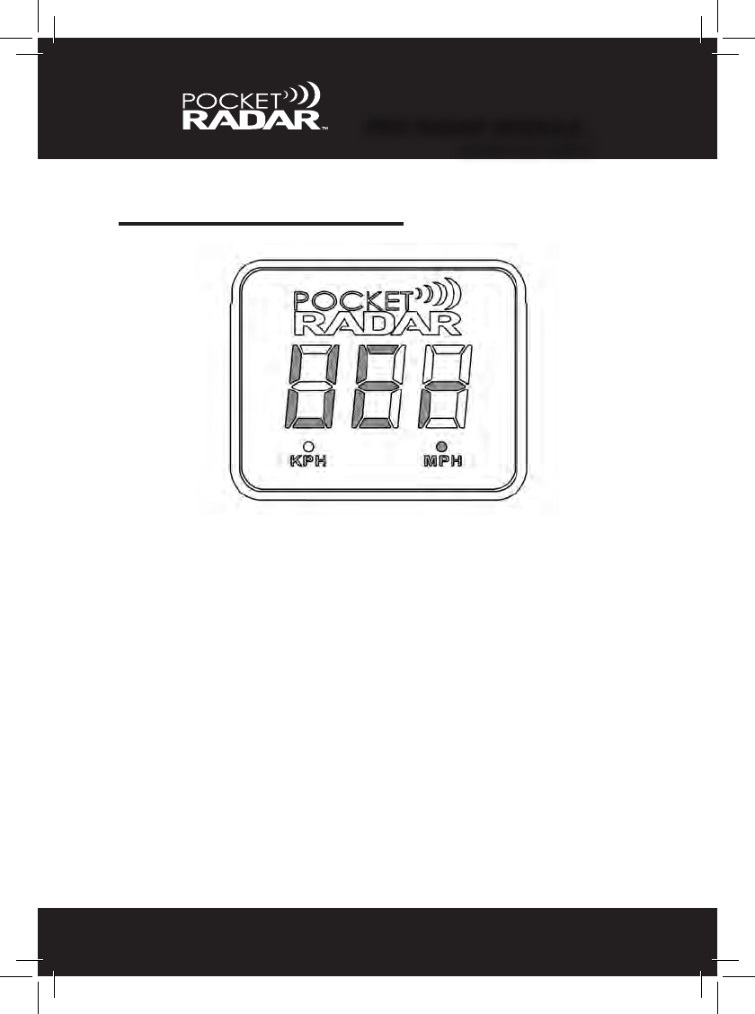
PRODUCT TOUR
3
Smart Display
Front Back
Bottom
1. KPH units indicator or brightness sensor 10. Indicator light for USB power
2. MPH units indicator or brightness sensor 11. USB out to radar
3. 3 Digit 7 segment speed display 12. Adjustable handle
4. Battery door 13. Tripod mounting nut
5. Instruction label 14. Slots for tripod alignment pins
6. Cable slots for USB Power Packs
7. Power / Selection button (red)
8. Recall / Mode button (black)
9. USB power input
12
3
4
5
6
13
14
Side
7
8
11
10
9
12
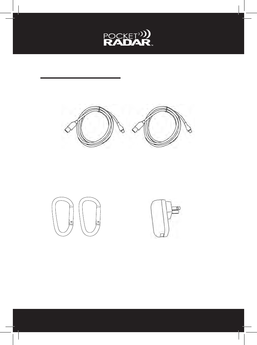
ACCESSORIES
4
One 2 amp AC power supply (USB charger)
Two 6 ft (2 meter) USB cables Type A to Micro B
Two carabiners
Included
The cables are used to connect your radar device to the
Smart Display, as well as provide USB power.
The carabiners are used to
hang the Smart Display onto
a fence or camera tripod. See
Mounting Options on page 6.
The AC power supply is used
to provide power via USB.
5
ACCESSORIES
Not Included
USB Power Packs USB Power Packs are
available in several sizes
and power ratings. Small
ones should provide over
5 hours of use from a fresh
charge.
Alkaline C-Size Batteries
Camera Tripod
A Deluxe Tripod
may be purchased
through the Pocket
Radar online store.
4 Alkaline C-size batteries
provide up to 14 hours of
use with the Smart Display.
USB cables are only useful
up to 6 feet (2 meters) in
length. If you plan to set
up the Smart Display more
than 6 feet apart from your
radar, this Extender Kit
is available through the
Pocket Radar online store.
50 foot USB Extender Cable Kit
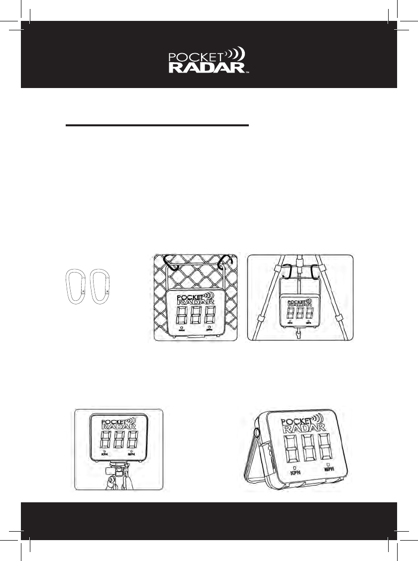
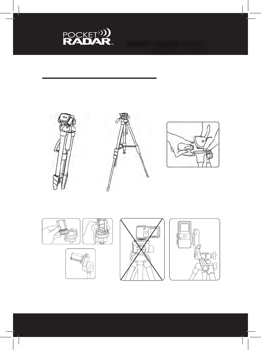
MOUNTING OPTIONS
6
The Smart Display has many different mounting/location options. The
Smart Display can be mounted to a metal fence using carabiners
(included), to a camera tripod using the tripod mount located on the
bottom, to the legs of a tripod with the carabiners, sitting on a chair or
table, hung on a wall using the handle or even standing on the ground
using the handle as a kickstand. Please refer to the illustrations below.
Two carabiners
Carabiners can be used to
mount the Smart Display
to a fence or the bottom of
a camera tripod.
Camera Tripod
See similar mounting steps
on pages 14 and 35.
Smart Display Kickstand
Located on back of
Smart Display.
SELECT YOUR RADAR
7
Pro Radar Module (pages 8-28)
Smart Coach radar (pages 29-46)
Front Bottom
3
2
1
1. Micro B USB connector
2. Slots for tripod alignment pins
3. Tripod mounting nut
4. Strain relief for USB cable (pass USB cable under this strap)
4
3
2
4
5
6
1
1. Speed display.
2. Trigger button to capture
speeds.
3. Mode/Recall button to
enter Constant-On
mode or Recall previous
25 speeds.
4. Micro-USB Connector
on the side of unit.
5. Radar lens aimed at the
ball in ight.
6. Battery compartment.
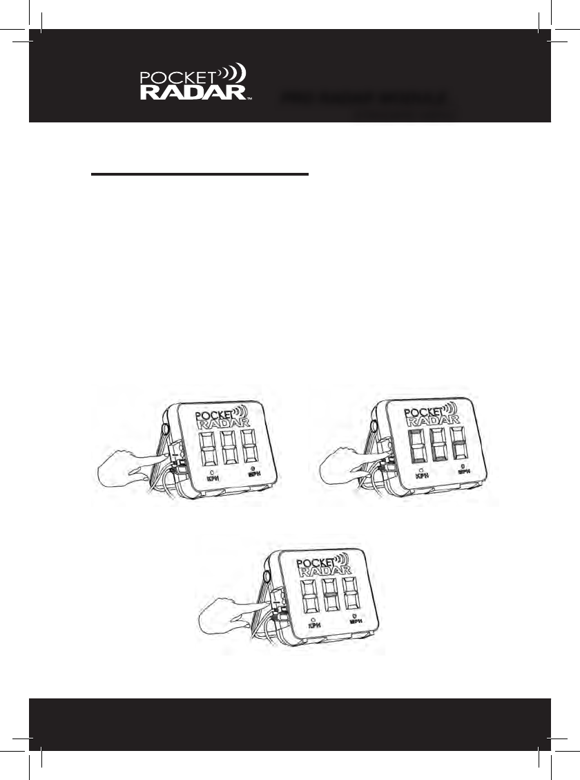
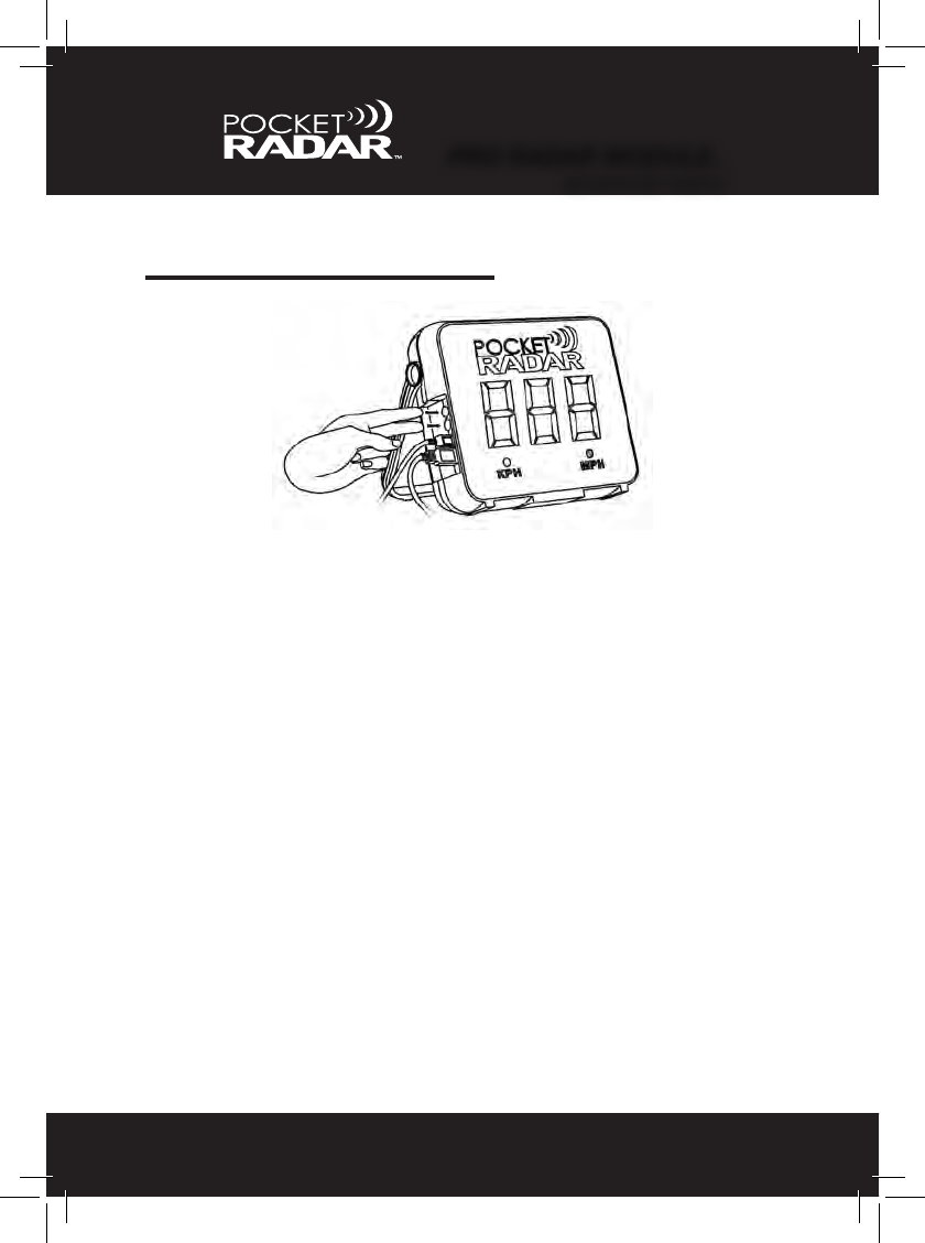
GETTING STARTED
8
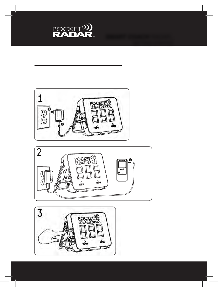
Set Up Instructions
1. Insert the small end of one of the 6 ft (2 meter) Type A to
Micro B cables into the Smart Display and the other end
into the 2 amp AC power supply (USB charger). Then plug
the 2 amp AC power supply into any power outlet.
2. Insert the small end of the other 6 ft (2 meter) Type A to
Micro B cable into the Pro Radar Module and the other end
into the Smart Display (pass USB cable under the plastic
Strain Relief strap).
3. Press the Power (red) button on the Smart Display, and
you’re ready to start capturing speeds.
•Seenextpageforillustrations.
If you plan on using standard Alkaline C-size batteries or a USB Power
Pack as your power source, please refer to page 15 in this Manual.
IMPORTANT NOTE: If the Pro Radar Module is not connected to
the Smart Display, “no rdr” will ash for 2 minutes until it powers off
automatically. To turn off the Smart Display, simply hold the Power (red)
button down for 1 second. Once “Off” is displayed, release the button
and the Smart Display is now turned off. Please note that the speed
memory stored in the Smart Display will be erased as well.
Pro Radar Module
PRO RADAR MODULE™
GETTING STARTED
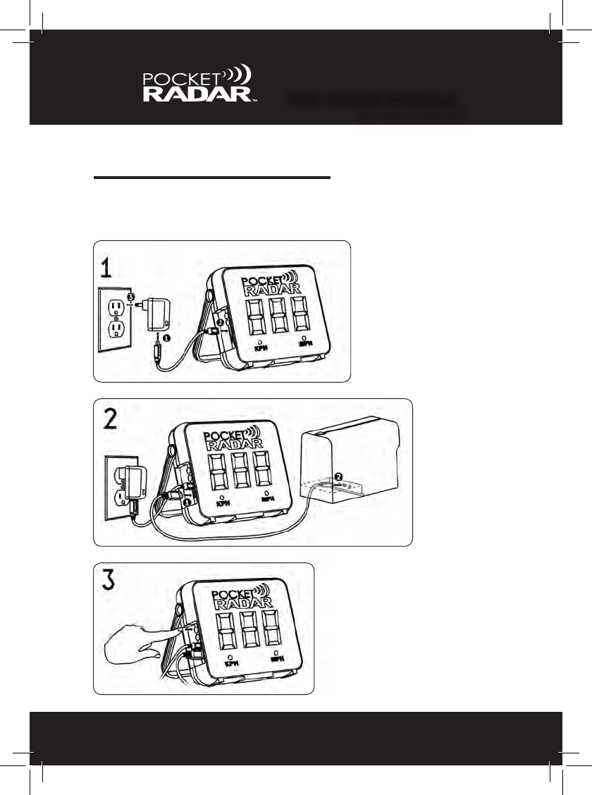
PRO RADAR MODULE™
9
GETTING STARTED
Set Up Illustrations
GETTING STARTED

PAIRING
10
To Pair the Smart Display to your Radar Module
for wireless operation, follow the steps below:
1. Use the supplied USB cable to temporarily connect the Smart
Display directly to your Radar Module by wired connection.
2. Hold down both the red and black buttons at the same time on
the Smart Display for 2 seconds to enter the advanced menu.
3. Release both buttons when ‘BLE’ is displayed. The display will
continuouslyash‘BLE’ while the pairing operation is in process.
4.Oncethe“BLE’turnssolidandstopsashing,theSmart
Display is then paired with the Radar Module and can be used
wirelessly.
PRO RADAR MODULE™
PAIRING

AIMING
11
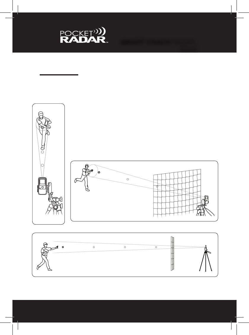
Must Aim Radar at Release Point
The Pro Radar Module captures a speed reading by sending out a
focused beam of very low power radio waves and looking for them to
bounce off a moving object, such as a ball. These radio waves are
focused in a small cone shaped like a ashlight beam which comes out
the front end, where the arrow is pointing, on the Pro Radar Module.
When positioning the Pro Radar Module, make sure it is set up and
aimed directly in line with the release point of the ball. This can either
be from behind or in front of the path of where the ball is coming from
(see pg. 49 to learn more about angles and how tilting down or up may
affect a speed reading). Make sure the beam of the Pro Radar Module
is not blocked or obstructed. Please refer to the illustrations on the
next page for examples of where the Pro Radar Module should be
positioned.
PRO RADAR MODULE™
AIMING
12
AIMING
Aiming Illustrations
Recommended Distance:
• Set up the Pro Radar Module either in front or behind the
path of the moving object.
• If throwing or hitting into a net, set up the Pro Radar Module
at least 15 feet behind the net or the player.
PRO RADAR MODULE™
AIMING
PRO RADAR MODULE™
SEPARATE ACCESSORIES
13
OPTIONAL ACCESSORIES
Using Smart Display with Pro Radar Module
USB Power Packs USB Power Packs are
available in several sizes
and power ratings. Small
ones should provide over
5 hours of use from a fresh
charge.
Alkaline C-Size Batteries
Camera Tripod
A Deluxe Tripod
may be purchased
through the Pocket
Radar online store.
4 Alkaline C-size batteries
provide up to 14 hours of
use with the Smart Display.
USB cables are only useful
up to 6 feet (2 meters) in
length. If you plan to set
up the Pro Radar Module
more than 6 feet apart
from the Smart Display,
this Extender Kit is avail-
able through the Pocket
Radar online store.
50 foot USB Extender Cable Kit

PRO RADAR MODULE™
MOUNTING OPTIONS
14
MOUNTING OPTIONS
2.1. 3.
4. 5.
Mounting to a Tripod
6.
Detach the tripod shoe that
screws into the bottom of
the Pro Radar Module.
Insert the tripod shoe into the
Pro Radar Module screw area
with the alignment pin in the slot.
Using ngers or a coin,
screw the tripod shoe into
the Pro Radar Module.
Attach the tripod shoe
and Pro Radar Module
back onto the tripod.
Questions? Visit www.PocketRadar.com/PRS for helpful video tutorials
or call us toll-free at 888-381-2672
POWER OPTIONS
15
Standard Batteries
If powered via Alkaline C-size batteries, after the Self Test passes, the
Smart Display will ash “bat” for 1 second and then the current battery
level (either Lo, 1, 2, 3 or 4) for another second. Typical battery life with
Alkaline C-size batteries is 14 hours. See table below:
The Smart Display and Pro Radar Module combo can be powered
either using USB connection or Alkaline C-size batteries. This makes it
extremely portable and exible for indoor and outdoor use.
Power On - Self Test
If powered via USB or batteries, the Smart Display will ash “888” for 2
seconds, after pressing the Power (red) button. That means the Self
Test has passed and you are ready to start capturing speeds. If the
Self Test fails, then an error code will be displayed. The error code will
include “E #”, where the # species the error number (example: E 4).
This error code will ash every second for 2 minutes until it powers off
automatically. See Page 51 for more about Error Codes.
USB Powered
When using a USB Power Pack, the battery life will be dictated by the
specs of the Power Pack. See Page 13 for more about USB Power
Pack options.
Level Remaining Life
Lo / Bat
1
2
3
4100% to 76%
25% to 5%
Less than 20 minutes
75% to 51%
50% to 26%
PRO RADAR MODULE™
POWER OPTIONS

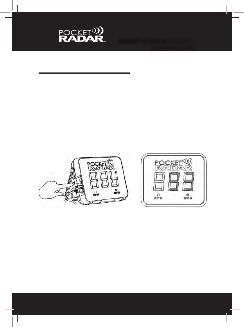
STANDARD MENU
16
Recall Memory
The Smart Display stores the previous 25 speeds in the memory. Each
time a speed is collected, the most recent speed is stored, and the
oldest of the 25 speeds is discarded.
To access the Recall memory, “TAP” the Mode (black) button on the
Smart Display. The most recent speed will display. Cycle through the
previous 25 speeds by repeatedly TAPPING the button, as shown below.
If there are no speeds stored in the memory or you reach the end of
the list, then it will display “-”. To exit the Recall Memory menu, simply
press the Power (red) button or else it will automatically exit after 45
seconds of inactivity.
NOTE: The Memory Recall list will be cleared automatically as soon as
the Smart Display is turned off or any advanced settings are modied.
PRO RADAR MODULE™
STANDARD MENU
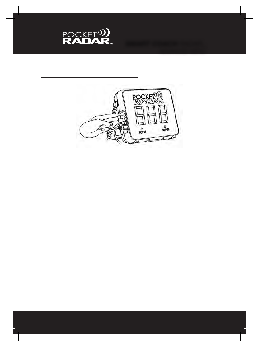
STANDARD MENU
17
Clear Memory
Sometimes it’s better to start fresh when beginning a new session. To
eliminate the previous speeds that are stored in the Smart Display, all
you need to do is “Press and Hold” the Mode (black) button down for 2
seconds until the word "CLr” displays. Once you see “CLr”, release the
button and a “-” will appear. That means the memory has been deleted
and you are now ready to capture new speeds.
1. 2.
3.
PRO RADAR MODULE™
STANDARD MENU
STANDARD MENU
18
USB / Battery Power Level
The Smart Display offers unique exibility with either USB or battery
powered options. To view battery life or USB, simply “Press and Hold”
the Mode (black) button down for 3.5 seconds. Once you see the word
“bat”, release the button. You will either see the word “USB” showing
that you are using USB power, or you will see the “Lo, 1, 2, 3, or 4”
showing how much battery life is left on your Alkaline C-size batteries.
See table on page 15 for more details.
1. 2.
3.
NOTE: If the Smart Display ashes “Lo / Bat” immediately change the
batteries. There are less than 20 minutes of operation remaining.
PRO RADAR MODULE™
STANDARD MENU
ADVANCED MENU
Holding down the Power (red) and Mode (black) buttons at the same
time for more than 2 seconds will bring the user into the advanced menu
listed below. Release both buttons when desired menu is shown.
1. Measurement Units (vnt): see page 20
• Allows the user to change units of measurement between
either MPH or KPH.
2. Sensitivity / Range (sen): see pages 21 and 26
• Allows the user to control the sensitivity and measurement
modes of the Pro Radar Module.
3. Auto - Off / Power - Off Timer (tof): see page 22
• Allows the user to specify how long the Display should re-
main on before it automatically turns off.
4. Auto - On (aon): see page 23
• Allows the user to have the system automatically turn on
when external power is supplied. Useful in permanent
installations.
5. Brightness (br): see page 24
• Allows the user to manually adjust the visibility of the Display
from Auto (default) to Low (dim) or High (very bright).
6. Version (Uer): see page 25
• Allows the user to identify which version of rmware
their Smart Display or radar contains.
19
PRO RADAR MODULE™
ADVANCED MENU

ADVANCED MENU
Measurement Units
The rst menu feature is the option to alternate between miles per hour
(MPH) and kilometers per hour (KPH). Hold down the Power (red) and
Mode (black) buttons for 2 seconds and "vnt” will appear.
• Releasing the Power (red) and Mode (black) buttons while “vnt” is
displayed will bring the user into the selection menu.
- Current unit (MPH or KPH) LED will ash every 0.5 seconds.
- Pressing the Power (red) button will cycle the user through
MPH or KPH indicators.
- Pressing the Mode (black) button locks in your choice and
resumes normal operation; Current selection on the display is
saved as the new units.
- Not cycling for 45 seconds will not update the current units,
and automatically exits the menu.
•Thefactorydefaultsettingismilesperhour(MPH)(See page 27 to
Learn More)
20
PRO RADAR MODULE™
ADVANCED MENU

ADVANCED MENU
21
Sensitivity / Range
The second menu feature is the option to control the sensitivity and
measurement modes of the Pro Radar Module. Hold down the Power
(red) and Mode (black) buttons for 3.5 seconds and “Sen” will appear.
• Releasing the Power (red) and Mode (black) buttons while “Sen” is
displayed will bring the user into the selection menu.
- "Sen” and the selected value will alternate every 1 second.
- Pressing the Power (red) button will cycle the user
through levels 1-10. (See page 26 for details)
- Pressing the Mode (black) button locks in your choice and
resumes normal operation; Current selection on the display is
saved as the new setting.
- Not cycling for 45 seconds will not update the curent value,
and automatically exits the menu.
•Thefactorydefaultsettingis10 (See page 27 for Important Details)
PRO RADAR MODULE™
ADVANCED MENU

ADVANCED MENU
22
Auto - Off / Power - Off Timer
The third menu feature is the option to specify how long the Display
should remain on before it automatically turns off after no readings. Hold
down the Power (red) and Mode (black) buttons for 5 seconds and "tof”
will appear.
• Releasing the Power (red) and Mode (black) buttons while “tof” is
displayed will bring the user into the selection menu.
- “tof” and the selected time will alternate every 1 second.
- Pressing the Power (red) button will cycle the user through
the different timer options (no, 5, 15, 30, 60). “No” means
indenitely, while 5 - 60 are in minutes.
- Pressing the Mode (black) button locks in your choice and
resumes normal operation; Current selection on the display is
saved as the new timer value.
- Not cycling for 45 seconds will not update the current value,
and automatically exits the menu.
•Thefactorydefaultsettingis15 minutes (See page 27 to Learn More)
PRO RADAR MODULE™
ADVANCED MENU

ADVANCED MENU
23
Auto - On
The fourth menu feature is the option to automatically turn on the Display
when plugged in using a USB power source. Hold down the Power (red)
and Mode (black) buttons for 6.5 seconds and "aon” will appear.
• Releasing the Power (red) and Mode (black) buttons while “aon” is
displayed will bring the user into the selection menu.
- “aon” and the selected mode will alternate every 1 second.
- Pressing the Power (red) button will cycle the user through
the different auto options (Yes or No). “Yes” means auto - on
is set up, while “No” means auto - on is not set up.
- Pressing the Mode (black) button locks in your choice and
resumes normal operation; Current selection on the display is
saved as the new auto-on mode.
- Not cycling for 45 seconds will not update the current value,
and automatically exits the menu.”
•Thefactorydefaultsettingis"no” (See page 27 to Learn More)
PRO RADAR MODULE™
ADVANCED MENU
ADVANCED MENU
24
Brightness
The fth menu feature is the option to adjust the visibility of the Display
in 3 different levels: Auto, Low and High. Hold down the Power (red) and
Mode (black) buttons for 8 seconds and "br” will appear.
• Releasing the Power (red) and Mode (black) buttons while “br” is
displayed will bring the user into the selection menu.
- “br” and the selected mode will alternate every 1 second.
- Pressing the Power (red) button will cycle the user through
three different brightness levels (avt, Lo and Hi): “avt”
means automatic, while “Lo” is dim and “Hi” is very bright.
- Pressing the Mode (black) button locks in your choice and
resumes normal operation; Current selection on the display is
saved as the new brightness mode.
- Not cycling for 45 seconds will not update the current choice,
and automatically exits the menu.
•Thefactorydefaultsettingis"Avt” (See page 27 to Learn More)
PRO RADAR MODULE™
ADVANCED MENU
ADVANCED MENU
25
Version
The sixth and nal menu feature is the identication of the rmware the
Smart Display contains. Hold down the Power (red) and Mode (black)
buttons for 9.5 seconds and "Uer” will appear.
• Releasing the Power (red) and Mode (black) buttons while “Uer” is
displayed will bring the user into the selection menu.
- “Dsp” or “rdr” and the version number will alternate every 1
second.
- Pressing the Power (red) button will cycle the user
through “Dsp” and version number of the Display, or “rdr” and
version number of the Pro Radar Module.
- Pressing the Mode (black) button or leaving untouched for 45
seconds will exit the menu.
•Thisinformationisonlynecessaryifyouarecontacting
Pocket Radar for support.
PRO RADAR MODULE™
ADVANCED MENU

SENSITIVITY SETTINGS
26
The Smart Display and Pro Radar Module have adjustable sensitivity
and different operating modes to allow users to optimize the operation for
different types of measurement setups. If you are experiencing interfer-
ence that causes false readings or “ghost readings”, try to adjust the
sensitivity level down to the lowest setting within each operating mode
described below, that will still pick up the ball. This can help minimize the
effects of any interference in the environment.
There are 10 sensitivity settings available in the advanced features
menu. Here is a description of the different operating modes for each
sensitivity setting:
•Setting10 – This is the default setting. It is a general purpose
mode and is the most sensitive.
•Settings9to6 – These settings are best for measuring a ball
that travels at least 30 feet or more. In this mode, setting 9 is
the most sensitive and setting 6 is the least sensitive.
•Settings5to4 – These settings are a special mode to be
used with dimpled practice balls or for measuring
Ball Exit Speed / Exit Velocity off the bat on a ball that travels
at least 30 feet or more. In this mode, setting 5 is the most
sensitive and setting 4 is the least sensitive.
•Settings3to1 – These settings are best for measuring close
up when hitting into a net where the ball is in ight and travels
10 to 30 feet. In this mode, setting 3 is the most sensitive and
setting 1 is the least sensitive. Use setting 1 for very close
work on large objects like a volleyball or soccer ball.
If you need any further help on how to decide on the best settings for
your measurement set up, please contact us toll-free at 888-381-2672
or by e-mail at Support@PocketRadar.com
PRO RADAR MODULE™
SENSITIVITY SETTINGS
Note: Sensitivity Settings are not available with the Smart Coach radar

27
PRO RADAR MODULE™
FACTORY DEFAULT SETTINGS
FACTORY DEFAULT SETTINGS
Measurement Units: MPH (miles per hour)
• The Smart Display out of the box will be set to miles per hour instead
of kilometers per hour because it is the unit preference of most of our
users.
Sensitivity / Range: 10
• The Pro Radar Module has a factory default setting for the most
general purpose operating mode and the maximum possible range.
NOT AVAILABLE FOR USE WITH SMART COACH RADAR.
Auto - Off / Power - Off Timer: 15 Minutes
• The Pro Radar System will automatically turn off after 15 minutes of
no activity while on batteries. This is a good balance which ensures the
system will not shut off prematurely, but still maximizes the battery life
available from a set of Alkaline C-size batteries.
Auto - On: No
• Most users will nd that they do not want the Pro Radar System to
automatically power on when plugged in to a USB power source. The
Auto-On setting is not for all users. It is good for permanent installations
that want to have it power on when the AC power is turned on.
Brightness: Auto
• The Pro Radar System Auto mode will switch the display between
Lo and Hi automatically depending on ambient lighting conditions.
Outdoors on a sunny day, the display will automatically brighten when
showing speeds to enable further distance viewing.

28
SPECIFICATIONS
Nominal Operating Frequency: K-Band 24.125 GHz
Measures from: 25 to 130 MPH (40 to 209 KPH)
Accuracy: +/- 1 MPH (+/- 2 KPH)
Range under good measurement conditions:
Baseball up to 200 feet and Larger Objects up to 300 feet.
Size: Smart Display
Height (8.75 inches), Width (11 inches), Depth (2.75 inches)
Pro Radar Module
Height (5.75 inches), Width (4 inches), Depth (8 inches)
Weight: Smart Display
2 lbs. 6 oz. (without 4 Alkaline C-size batteries)
3 lbs. 0 oz. (with 4 Alkaline C-size batteries)
Pro Radar Module
2 lbs. 2 oz.
Typical Battery Life:
14 hours with 4 Alkaline C-size batteries (not included)
Operating Temperature Range: -22° F to 140° F (-30° C to 60° C)
Storage Temperature: -40° F to 185° F (-40° C to 85° C)
Memory Recall function: 25 readings deep
PRO RADAR MODULE™
SPECIFICATIONS
Skip to Page 47 if you do not have a Smart Coach radar
29
SMART COACH RADAR™
GETTING STARTED
GETTING STARTED
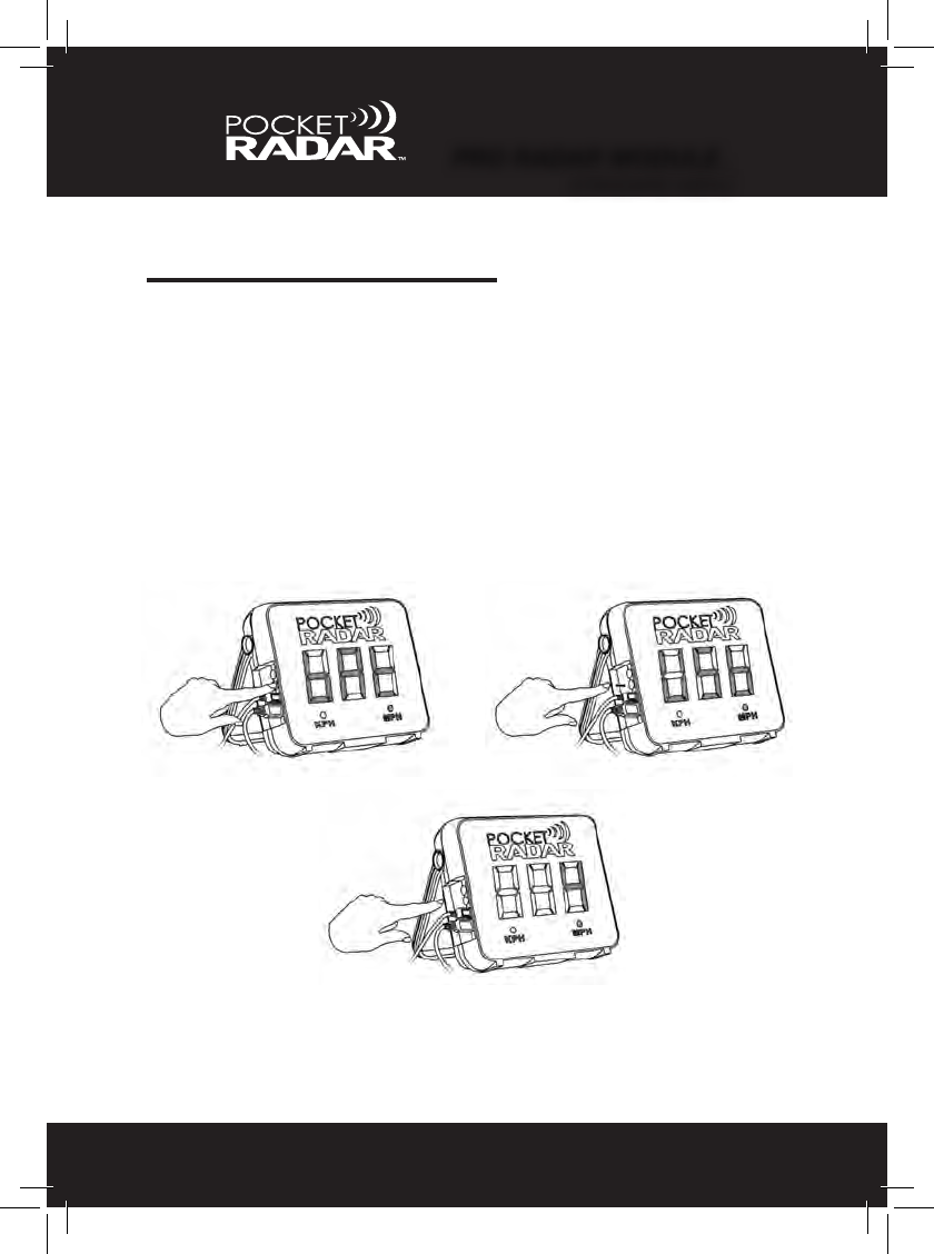
Set Up Instructions
1. Insert the small end of one of the 6 ft (2 meter) Type A to
Micro B cables into the Smart Display and the other end
into the 2 amp AC power supply (USB charger). Then plug
the 2 amp AC power supply into any power outlet.
2. Insert the small end of the other 6 ft (2 meter) Type A to
Micro B cable into the Smart Coach radar and the other
end into the Smart Display.
3. Press the Power (red) button on the Smart Display and
activate the Smart Coach radar, and you’re ready to start
capturing speeds.
•Seenextpageforillustrations.
If you plan on using standard Alkaline AAA batteries or a USB Power
Pack as your power source, please refer to page 36 in this Manual.
IMPORTANT NOTE: If the Smart Coach radar is not connected to
the Smart Display, “no rdr” will ash for 2 minutes until it powers off
automatically. To turn off the Smart Display, simply hold the Power (red)
button down for 1 second. Once “Off” is displayed, release the button
and the Smart Display is now turned off. Please note that the speed
memory stored in the Smart Display will be erased as well.
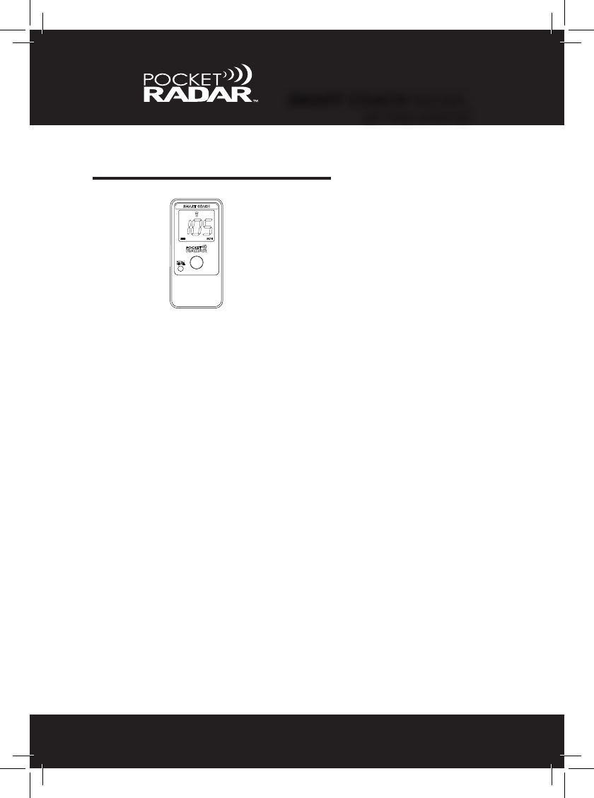
Smart Coach radar
GETTING STARTED
Set Up Illustrations
SMART COACH RADAR™
GETTING STARTED
30

SMART COACH RADAR™
PAIRING
31
PAIRING
To Pair the Smart Display to your Smart Coach for
wireless operation, follow the steps below:
1. Use the supplied USB cable to temporarily connect the Smart
Display directly to your Smart Coach radar by wired connection.
2. Hold down both the red and black buttons at the same time on
the Smart Display for 2 seconds to enter the advanced menu.
3. Release both buttons when ‘BLE’ is displayed. The display will
continuouslyash‘BLE’ while the pairing operation is in process.
4.Oncethe“BLE’turnssolidandstopsashing,theSmart
Display is then paired with the Smart Coach radar and can be
used wirelessly.

32
SMART COACH RADAR™
AIMING
AIMING
Must Aim Radar at Release Point
The Smart Coach radar captures a speed reading by sending out a
focused beam of very low power radio waves and looking for them to
bounce off a moving object, such as a ball. These radio waves are
focused in a small cone shaped like a ashlight beam which comes out
the back end of the Smart Coach radar.
When positioning the Smart Coach radar, make sure it is set up and
aimed directly in line with the release point of the ball. This can either
be from behind or in front of the path of where the ball is coming from
(see pg. 49 to learn more about angles and how tilting down or up may
affect a speed reading). Make sure the beam of the Smart Coach radar
is not blocked or obstructed. Please refer to the illustrations on the
next page for examples of where the Smart Coach radar should be
positioned.
SMART COACH RADAR™
AIMING
33
AIMING
Aiming Illustrations
Recommended Distance:
• Set up the Smart Coach radar either in front or behind the
path of the moving object.
• If throwing or hitting into a net, set up the Smart Coach radar
at least 15 feet behind the net or the player.
34
SMART COACH RADAR™
SEPARATE ACCESSORIES
OPTIONAL ACCESSORIES
Using Smart Display with Smart Coach radar
USB Power Packs USB Power Packs are
available in several sizes
and power ratings. Small
ones should provide over
5 hours of use from a fresh
charge.
Camera Tripod
A Deluxe Tripod
may be purchased
through the Pocket
Radar online store.
USB cables are only useful
up to 6 feet (2 meters) in
length. If you plan to set
up the Smart Coach radar
more than 6 feet apart
from the Smart Display,
this Extender Kit is avail-
able through the Pocket
Radar online store.
50 foot USB Extender Cable Kit
Right-Angled USB Cable
A 6 ft. Right-Angled USB Cable
may be purchased through the
Pocket Radar online store.
You will also need a Tripod Mount to
attach the Smart Coach radar to the
tripod (see pg. 35)
35
SMART COACH RADAR™
MOUNTING OPTIONS
MOUNTING OPTIONS
2.1. 3.
4. 5.
Mounting to a Tripod
6.
Detach the tripod shoe that
screws into the bottom of
the Tripod Mount.
Screw tripod mount into the tripod
shoe (using a coin helps). Clip tripod
mount/tripod shoe back into the tripod.
Flip tripod head to lateral position.
Incorrect set up Correct Set Up

SMART COACH RADAR™
POWER OPTIONS
36
POWER OPTIONS
Standard Batteries
If powered via Alkaline C-size batteries, after the Self Test passes, the
Smart Display will ash “bat” for 1 second and then the current battery
level (either Lo, 1, 2, 3 or 4) for another second. Typical battery life with
Alkaline C-size batteries is 14 hours. See table below:
The Smart Display and Smart Coach radar combo can be powered
either using USB connection or Alkaline C-size batteries. This makes it
extremely portable and exible for indoor and outdoor use. When con-
nected to the Smart Display, the Smart Coach radar will be powered via
the Display and not the internal AAA batteries.
Power On - Self Test
If powered via USB or batteries, the Smart Display will ash “888” for 2
seconds, after pressing the Power (red) button. That means the Self
Test has passed and you are ready to start capturing speeds. If the
Self Test fails, then an error code will be displayed. The error code will
include “E #”, where the # species the error number (example: E 4).
This error code will ash every second for 2 minutes until it powers off
automatically. See Page 51 for more about Error Codes.
USB Powered
When using a USB Power Pack, the battery life will be dictated by the
specs of the Power Pack. See Page 34 for more about USB Power
Pack options.
Level Remaining Life
Lo / Bat
1
2
3
4100% to 76%
25% to 5%
Less than 20 minutes
75% to 51%
50% to 26%

37
SMART COACH RADAR™
STANDARD MENU
STANDARD MENU
USB / Battery Power Level
The Smart Display offers unique exibility with either USB or battery
powered options. To view battery life or USB, simply “Press and Hold”
the Mode (black) button down for 2 seconds. Once you see the word
“bat”, release the button. You will either see the word “USB” showing
that you are using USB power, or you will see the “Lo, 1, 2, 3, or 4”
showing how much battery life is left on your Alkaline C-size batteries.
See table on page 36 for more details.
1. 2.
3.
NOTE: If the Smart Display ashes “Lo / Bat” immediately change the
batteries. There are less than 20 minutes of operation remaining.
SMART COACH RADAR™
STANDARD MENU
38
STANDARD MENU
Recall Memory
The Smart Display stores the previous 25 speeds in the memory. Each
time a speed is collected, the most recent speed is stored, and the
oldest of the 25 speeds is discarded.
To access the Recall memory, “TAP” the Mode (black) button on the
Smart Display. The most recent speed will display. Cycle through the
previous 25 speeds by repeatedly TAPPING the button, as shown below.
If there are no speeds stored in the memory or you reach the end of
the list, then it will display “-”. To exit the Recall Memory menu, simply
press the Power (red) button or else it will automatically exit after 45
seconds of inactivity.
NOTE: The Memory Recall list will be cleared automatically as soon as
the Smart Display is turned off or any advanced settings are modied.
39
SMART COACH RADAR™
ADVANCED MENU
ADVANCED MENU
Holding down the Power (red) and Mode (black) buttons at the same
time for more than 2 seconds will bring the user into the advanced menu
listed below. Release both buttons when desired menu is shown.
1. Measurement Units (vnt): see page 40
• Allows the user to change units of measurement between
either MPH or KPH.
2. Auto - Off / Power - Off Timer (tof): see page 41
• Allows the user to specify how long the Display should re-
main on before it automatically turns off.
3. Auto - On (aon): see page 42
• Allows the user to have the system automatically turn on
when external power is supplied. Useful in permanent
installations.
4. Brightness (br): see page 43
• Allows the user to manually adjust the visibility of the Display
from Auto (default) to Low (dim) or High (very bright).
5. Version (Uer): see page 44
• Allows the user to identify which version of rmware
their Smart Display or radar contains.
SMART COACH RADAR™
ADVANCED MENU
40
ADVANCED MENU
Measurement Units
The rst menu feature is the option to alternate between miles per hour
(MPH) and kilometers per hour (KPH). Hold down the Power (red) and
Mode (black) buttons for 2 seconds and "vnt” will appear.
• Releasing the Power (red) and Mode (black) buttons while “vnt” is
displayed will bring the user into the selection menu.
- Current unit (MPH or KPH) LED will ash every 0.5 seconds.
- Pressing the Power (red) button will cycle the user through
MPH or KPH indicators.
- Pressing the Mode (black) button locks in your choice and
resumes normal operation; Current selection on the display is
saved as the new units.
- Not cycling for 45 seconds will not update the current units,
and automatically exits the menu.
•Thefactorydefaultsettingismilesperhour(MPH)(See page 45 to
Learn More)
ADVANCED MENU
41
Auto - Off / Power - Off Timer
The second menu feature sets how long the Display and Smart Coach
radar stays in Constant-On mode. Hold down the Power (red) and Mode
(black) buttons for 3.5 seconds and "tof” will appear.
• Releasing the Power (red) and Mode (black) buttons while “tof” is
displayed will bring the user into the selection menu.
- “tof” and the selected time will alternate every 1 second.
- Pressing the Power (red) button will cycle the user through
the different timer options (no, 5, 15, 30, 60). “No” means
indenitely, while 5 - 60 are in minutes.
- Pressing the Mode (black) button locks in your choice and
resumes normal operation; Current selection on the display is
saved as the new timer value.
- Not cycling for 45 seconds will not update the current value,
and automatically exits the menu.
•Thefactorydefaultsettingis15 minutes (See page 45 to Learn More)
SMART COACH RADAR™
ADVANCED MENU

ADVANCED MENU
42
Auto - On
The third menu feature is the option to automatically turn on the Display
and radar when plugged in using a USB power source. Hold down the
Power (red) and Mode (black) buttons for 5 seconds and "aon” will appear.
• Releasing the Power (red) and Mode (black) buttons while “aon” is
displayed will bring the user into the selection menu.
- “aon” and the selected mode will alternate every 1 second.
- Pressing the Power (red) button will cycle the user through
the different auto options (Yes or No). “Yes” means auto - on
is set up, while “No” means auto - on is not set up.
- Pressing the Mode (black) button locks in your choice and
resumes normal operation; Current selection on the display is
saved as the new auto-on mode.
- Not cycling for 45 seconds will not update the current value,
and automatically exits the menu.”
•Thefactorydefaultsettingis"no” (See page 45 to Learn More)
SMART COACH RADAR™
ADVANCED MENU

ADVANCED MENU
43
Brightness
The fourth menu feature is the option to adjust the visibility of the Dis-
play in 3 different levels: Auto, Low and High. Hold down the Power (red)
and Mode (black) buttons for 6.5 seconds and "br” will appear.
• Releasing the Power (red) and Mode (black) buttons while “br” is
displayed will bring the user into the selection menu.
- “br” and the selected mode will alternate every 1 second.
- Pressing the Power (red) button will cycle the user through
three different brightness levels (avt, Lo and Hi): “avt”
means automatic, while “Lo” is dim and “Hi” is very bright.
- Pressing the Mode (black) button locks in your choice and
resumes normal operation; Current selection on the display is
saved as the new brightness mode.
- Not cycling for 45 seconds will not update the current choice,
and automatically exits the menu.
•Thefactorydefaultsettingis"Avt” (See page 45 to Learn More)
SMART COACH RADAR™
ADVANCED MENU

ADVANCED MENU
44
Version
The fth and nal menu feature is the identication of the rmware the
Smart Display contains. Hold down the Power (red) and Mode (black)
buttons for 8 seconds and "Uer” will appear.
• Releasing the Power (red) and Mode (black) buttons while “Uer” is
displayed will bring the user into the selection menu.
- “Dsp” or “rdr” and the version number will alternate every 1
second.
- Pressing the Power (red) button will cycle the user
through “Dsp” and version number of the Display, or “rdr” and
version number of the Smart Coach radar.
- Pressing the Mode (black) button or leaving untouched for 45
seconds will exit the menu.
•Thisinformationisonlynecessaryifyouarecontacting
Pocket Radar for support.
SMART COACH RADAR™
ADVANCED MENU

45
SMART COACH RADAR™
FACTORY DEFAULT SETTINGS
FACTORY DEFAULT SETTINGS
Measurement Units: MPH (miles per hour)
• The Smart Display and Smart Coah radar out of their boxes will be
set to miles per hour instead of kilometers per hour because it is the unit
preference of most of our users.
Auto - Off / Power - Off Timer: 15 Minutes
• The Smart Display and Smart Coach radar combo will automatically
drop out of Constant-On mode after 15 minutes of no speeds while us-
ing batteries. If the Smart Coach radar is connected to the App, the App
can turn it back on remotely for up to 30 minutes. After which the Smart
Display will shut down completely.
Auto - On: No
• Most users will nd that they do not want the Smart Display and
Smart Coach radar combo to automatically power on when plugged in
to a USB power source. The Auto-On setting is not for all users. It is
good for permanent installations that want to have it power on when the
AC power is turned on.
Brightness: Auto
• Auto mode will switch the display between Lo and Hi automatically
depending on ambient lighting conditions. Outdoors on a sunny day,
the display will automatically brighten when showing speeds to enable
further distance viewing.

46
SMART COACH RADAR™
SPECIFICATIONS
SPECIFICATIONS
Nominal Operating Frequency: K-Band 24.125 GHz
Measures from: 25 to 130 MPH (40 to 209 KPH)
Accuracy: +/- 1 MPH (+/- 2 KPH)
Range under good measurement conditions:
Baseball up to 120 feet and Larger Objects up to 200 feet.
Size: Smart Display
Height (8.75 inches), Width (11 inches), Depth (2.75 inches)
Smart Coach Radar
Height (4.7 inches), Width (2.3 inches), Depth (0.8 inches)
Weight: Smart Display
2 lbs. 6 oz. (without 4 Alkaline C-size batteries)
3 lbs. 0 oz. (with 4 Alkaline C-size batteries)
Smart Coach Radar
4.5 oz. with 2 AAA Alkaline batteries (included)
Typical Battery Life:
14 hours in Constant-On Mode or 4,000 manual button
presses using 4 Alkaline C-size batteries (not included)
Operating Temperature Range: -22° F to 140° F (-30° C to 60° C)
Storage Temperature: -40° F to 185° F (-40° C to 85° C)
Memory Recall function: 25 readings deep
TROUBLESHOOTING
47
Interference
Certain types of interference can cause all radar equipment to some-
times display false or so called “ghost readings,” or make it harder to
capture the speed of the intended object.
Movement: Any objects that rotate, move or vibrate can create a read-
ing. Large amounts of vibration, such as very loud noises, can result in
false readings. Things like motors, fans, nearby trafc or the movement
of tree leaves can be detected by Radar device. In some cases, if you
are measuring speeds on a eld near a roadway, you may pick up the
speed of a car in the distance.
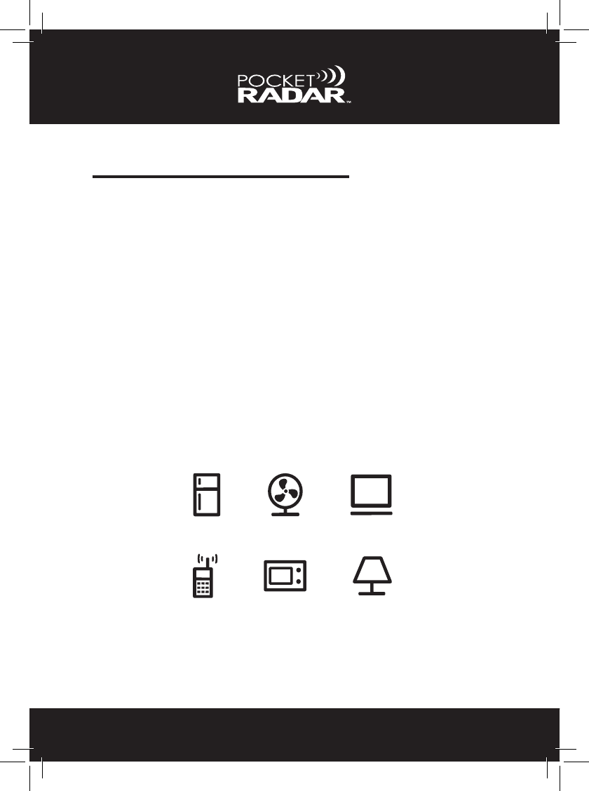
Electrical: Cell phones, cell towers, wireless devices, radio and TV
transmitters, computers, uorescent lights, televisions, walkie-talkies,
etc., can also possibly create a false reading.
Appliances
Cell Phones
Computers
Florescent Bulbs
Fan Motion
Microwaves
One technique to test for interference is to make a measurement in the
same direction with no obvious object in motion and see if you get a
speed to display.

TROUBLESHOOTING
48
Ghost Readings
Radar devices are very sensitive instruments for measuring moving
objects of any kind. There may be times when the speed reading
displayed may not make sense, or when there is no apparent moving
object present. False readings of this kind are sometimes referred to
as “ghost readings”. These can result from either a movement of some
kind, such as a fan or hidden moving object, or an electrical source of
interference, such as a uorescent light, neon sign, computer monitor,
cell phone or cell phone tower nearby.
You will need to use your own judgment to decide if the speed measure-
ment makes sense. If the speed doesn’t make sense, you may have
a false reading. An example would be if the Display ashes 107 mph,
when you know the ball speed shouldn’t be any higher than 65 mph.
The radar devices have software designed to ignore most of these
false ghost readings, but in certain cases there may be things in your
environment that may cause interference.
Tips to Eliminate Interference
If you are capturing random speed readings, there may be a solution to
your problem. Here are a few tips that may help:
• Change the Sensitivity / Range level of the Pro Radar
Module to a different setting. See page 20 for details.
• Use the lowest setting in the operating mode in your set up
that will reliably get the object speed that you want.
• If the Radar device is positioned behind the release
point, try changing the location to be in front.

49
TROUBLESHOOTING
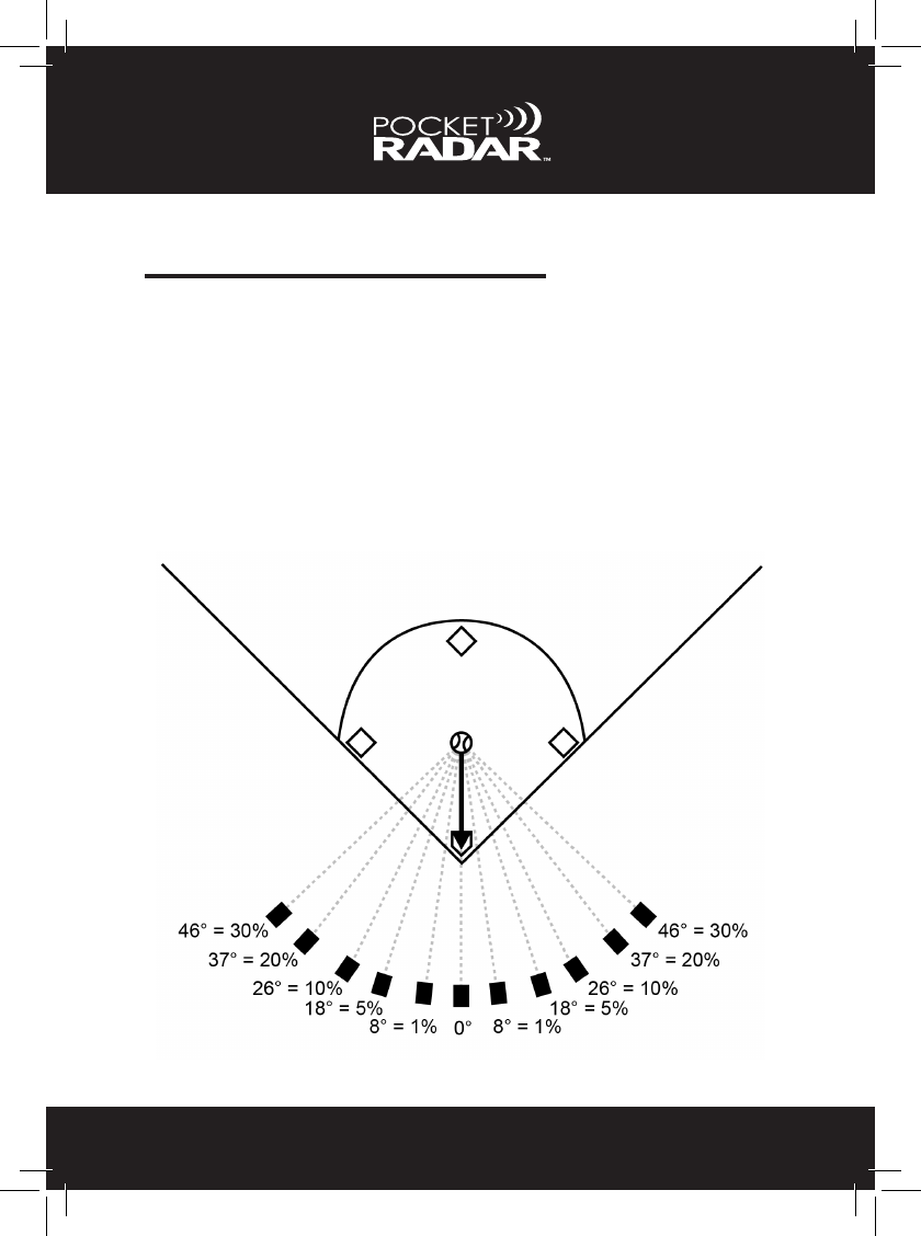
Angles
A common mistake made with ALL radar equipment is trying to measure
the speed of an object at an angle. Due to the nature of how Doppler
speed radar works, the radar device will measure most accurate speeds
when the object is moving directly towards or away from the radar
beam. If you set up the radar’s beam even a slight angle sideways to
the path of the moving object, you will measure a SLOWER speed than
the object actually travels along its path. At slight angles the error is
very small; however at larger angles the error can become substantial.
Please refer to the table below for speeds related to off-angle issues.
50
TROUBLESHOOTING
Cosine Error
This off angle speed measurement error is referred to as the COSINE
error, named after the mathematical function that allows you to calculate
the exact speed versus angle. The measured speed will always read
lower than the actual speed as you move off the centerline of the path
of the moving object. For small angles, this error will be very small. This
is why you see police ofcers pointing their radar along the direction of
the road; not down a side street pointing sideways to the road.
Each degree from center will cause your speed to read the noted % lower.
51
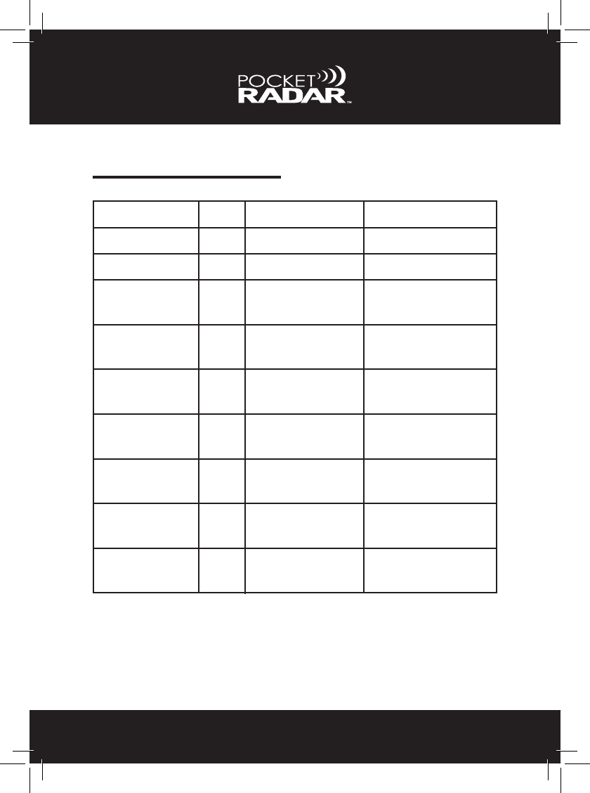
ERROR CODES
No Radar
Low Battery
Unsupported
Device
External Power
Failure
Internal Power
Failure
Communication
Failure
Radar Version
Failure
Internal
Overow
Flash Memory
Failure
No / rdr
Lo / Bat
E 1
E 2
E 3
E 4
ERROR: CODE: EXPLANATION: FIX:
Radar is not connected Connect radar device
There is 20 minutes left
of power on the batteries
Unsupported radar
device connected to the
Smart Display
Replace batteries
External Power Supply
has failed, possibly
overloaded
Internal Power Supply
has failed, possibly a
mechanical issue
An issue has occurred
in communication with
the radar device
Unsupported radar
device connected to the
Smart Display
An issue has occurred in
communication with the
radar device
Conguration value not
correctly saved
Connect supported radar
device to Smart Display.
Contact support for help
Disconnect / reconnect
radar device. If not re-
solved, contact support
Disconnect / reconnect
all power. If not resolved,
contact support
Disconnect / reconnect
all power. If not resolved,
contact support
Connect supported Radar
Module to Smart Display.
Contact support for help
Disconnect / reconnect
all power. If not resolved,
contact support
Disconnect / reconnect
all power. If not resolved,
contact support
E 9
E16
E19
Need help? Please contact Pocket Radar, Inc. You can reach us toll-free
at 888-381-2672 or by e-mail at Support@PocketRadar.com

52
FCC CLASS B STATEMENT
FCC Class B Product Label Statement
This device complies with part 15 of the FCC Rules. Operation is subject to the
following two conditions: (1) This device may not cause harmful interference, and
(2) this device must accept any interference received, including interference that
may cause undesired operation.
FCC Class B User Manual Statement
NOTE: This equipment has been tested and found to comply with the limits for
a Class B digital device, pursuant to part 15 of the FCC Rules. These limits are
designed to provide reasonable protection against harmful interference in a
residential installation. This equipment generates, uses and can radiate radio fre-
quency energy and, if not installed and used in accordance with the instructions,
may cause harmful interference to radio communications. However, there is no
guarantee that interference will not occur in a particular installation. If this equip-
ment does cause harmful interference to radio or television reception, which can
be determined by turning the equipment off and on, the user is encouraged to try
to correct the interference by one or more of the following measures:
• Reorient or relocate the receiving antenna.
• Increase the separation between the equipment and receiver.
• Connect the equipment into an outlet on a circuit different from that to which
the receiver is connected.
• Consult the dealer or an experienced radio/TV technician for help.
NOTE: Changes or modications not expressly approved by the
party responsible for compliance may void the user’s authority to
operate the equipment.
Not intended for Law Enforcement Use.

53
WARRANTY INFORMATION
Limited Warranty
– Pocket Radar, Inc. warrants to the original purchaser that this product will be
free of defects in workmanship and materials for a period of two years from the
date of purchase.
– If the product is found by Pocket Radar, Inc. to be defective, Pocket Radar,
Inc’s entire liability and your exclusive remedy for breach of warranty shall be
that Pocket Radar, Inc. will repair or replace the product and return the product
or its replacement to you at no charge. Provided that you ship the product to
Pocket Radar, Inc. in an authorized RMA shipping package with a description of
the defect and subject to the other conditions of this warranty. Should the product
prove to not be repairable, Pocket Radar, Inc. may substitute an equivalent
product of the same or similar style and of a value not lesser than the original
purchase price of your instrument.
– Pocket Radar, Inc. warrants the repaired or replacement product to be free
from defects in material and workmanship on the same terms as the product
originally purchased. This warranty will be void if the product, serial number or
other identication marks have been defaced, damaged or removed. This war-
ranty does not cover wear and tear due to normal use, or damage to the product
as the result of improper usage, neglect of care, alteration, accident or unauthor-
ized repair, nor does this warranty apply to the batteries necessary to operate the
product.
– This warranty is extended to the original retail purchaser only and may not be
transferred or assigned to subsequent owners. In order to validate your warranty,
you must provide proof of purchase acceptable to Pocket Radar, Inc. together
with the product for warranty repair/replacement.
– Products returned to Pocket Radar, Inc. must be pre-authorized by Pocket
Radar, Inc. and must be returned in an authorized RMA (Return Material Autho-
rization) packaging. Please contact Pocket Radar, Inc. to obtain information on
authorized packaging and to obtain return instructions or for any other question
regarding this warranty.

54
WARRANTY INFORMATION
Limited Warranty cont.
– THE FOREGOING WARRANTY IS GIVEN IN LIEU OF AND POCKET RA-
DAR, INC. DISCLAIMS ALL OTHER WARRANTIES OR REPRESENTATIONS,
EXPRESSED OR IMPLIED, IN FACT OR IN LAW, WITH RESPECT TO THIS
PRODUCT, INCLUDING, BUT NOT LIMITED TO, (1) THE IMPLIED WAR-
RANTIES OF MERCHANTABILITY AND OF FITNESS FOR A PARTICULAR
PURPOSE, OR (2) THAT USE OF THE PRODUCT WILL BE UNINTERRUPTED
AND ERROR FREE.
– Pocket Radar, Inc. shall have no liability for any indirect or speculative dam-
ages (including, but not limited to, consequential, incidental and special dam-
ages) relating to the use of or inability to use this product, whether arising out of
contract, negligence, tort, or under any warranty theory, or for infringement of any
other party’s intellectual property rights, irrespective of whether Pocket Radar,
Inc. had advance notice of the possibility of any such damages, including, but
not limited to, loss of use, revenue or prot. In no event shall Pocket Radar, Inc’s
total liability for all claims regarding the product exceed the price paid for the
product. Pocket Radar, Inc. neither assumes nor authorizes anyone to assume
for it any other liabilities.
– Some states do not allow the exclusion or limitation of incidental or consequen-
tial damages, so the above limitations or exclusions may not apply to you.
RETURN INFO
For US Customers:
If your Pocket Radar product is not working properly please
DO NOT RETURN TO THE RETAILER OR STORE.
We are here to help. Please contact Pocket Radar, Inc. and we will take
care of you. You can reach us toll-free at 888-381-2672 or by e-mail at
Support@PocketRadar.com