Invivo 2GMODSB WIRELESS ECG MODULE User Manual 989803184961
Invivo Corporation WIRELESS ECG MODULE 989803184961
Invivo >
USERS MANUAL
Expression MR200 MRI Patient Monitoring System
INSTRUCTIONS FOR USE
Revision B
English
*989803184961*
989803184961

ii
Manufacturer
Invivo,adivisionofPhilipsMedicalSystems
12151ResearchParkway
Orlando,FL32826
USA
877‐468‐4861
+31(0)499378299
www.invivocorp.com
Copyright
Copyright©2013,KoninklijkePhilipsN.V.
Allrightsreserved.
REF989803184961Rev.B,October2013
PrintedinUSA
Proprietary Information
Thisdocumentandtheinformationcontainedinitisproprietaryandconfidential
informationofKoninklijkePhilipsN.V. andmaynotbereproduced,copiedinwholeorin
part,adapted,modified,disclosedtoothers,ordisseminatedwithoutthepriorwritten
permissionoftheKoninklijkePhilipsN.V.Thisdocumentisintendedtobeusedbycustomers
andislicensedtothemaspartoftheirKoninklijkePhilipsN.V. equipmentpurchase.Useof
thisdocumentbyunauthorizedpersonsisstrictlyprohibited.
KoninklijkePhilipsN.V. providesthisdocumentwithoutwarrantyofanykind,impliedor
expressed,including,butnotlimitedto,theimpliedwarrantiesofmerchantabilityand
fitnessforaparticularpurpose.
KoninklijkePhilipsN.V. hastakencaretoensuretheaccuracyofthisdocument.However,
KoninklijkePhilipsN.V. assumesnoliabilityforerrorsoromissionsandreservestherightto
makechangeswithoutfurthernoticetoanyproductshereintoimprovereliability,function,
ordesign.KoninklijkePhilipsN.V. maymakeimprovementsorchangesintheproductsor
programsdescribedinthisdocumentatanytime.
Neweditionsofthisdocumentwillincorporateallmaterialupdatedsincetheprevious
edition.Updatepackagesmaybeissuedbetweeneditionsandcontainreplacementand
additionalpagestobemergedbyarevisiondateatthebottomofthepage.Notethatpages
whicharerearrangedduetochangesonapreviouspagearenotconsideredrevised.
Thedocumentationpartnumberandrevisionindicatethecurrentedition.Theprintingdate
changeswhenanewrevisionisprinted.(Minorcorrectionsandupdateswhichare
incorporatedatreprintdonotcausethedatetochange.)Thedocumentrevisionletter
changeswhenextensivetechnicalchangesareincorporated.
Contents
Contents 1
Manufacturer . . . . . . . . . . . . . . . . . . . . . . . . . . . . . . . . . . . . . . . . . . . . . . . . . . . . . . . . . .1-ii
Copyright . . . . . . . . . . . . . . . . . . . . . . . . . . . . . . . . . . . . . . . . . . . . . . . . . . . . . . . . . . . . .1-ii
Proprietary Information . . . . . . . . . . . . . . . . . . . . . . . . . . . . . . . . . . . . . . . . . . . . . . . . . . 1-ii
Chapter 1: Important Information
Intended Audience . . . . . . . . . . . . . . . . . . . . . . . . . . . . . . . . . . . . . . . . . . . . . . . . . . . . . . .1-1
Indications for Use . . . . . . . . . . . . . . . . . . . . . . . . . . . . . . . . . . . . . . . . . . . . . . . . . . . . . . .1-2
Conventions . . . . . . . . . . . . . . . . . . . . . . . . . . . . . . . . . . . . . . . . . . . . . . . . . . . . . . . . . . . . 1-2
System Conventions. . . . . . . . . . . . . . . . . . . . . . . . . . . . . . . . . . . . . . . . . . . . . . . . . . . . . . . . .1-2
Document Conventions . . . . . . . . . . . . . . . . . . . . . . . . . . . . . . . . . . . . . . . . . . . . . . . . . . . . . .1-3
Warnings . . . . . . . . . . . . . . . . . . . . . . . . . . . . . . . . . . . . . . . . . . . . . . . . . . . . . . . . . . . . .1-3
Cautions. . . . . . . . . . . . . . . . . . . . . . . . . . . . . . . . . . . . . . . . . . . . . . . . . . . . . . . . . . . . . .1-3
Notes . . . . . . . . . . . . . . . . . . . . . . . . . . . . . . . . . . . . . . . . . . . . . . . . . . . . . . . . . . . . . . . .1-3
Contraindications . . . . . . . . . . . . . . . . . . . . . . . . . . . . . . . . . . . . . . . . . . . . . . . . . . . . . . . .1-4
Safety. . . . . . . . . . . . . . . . . . . . . . . . . . . . . . . . . . . . . . . . . . . . . . . . . . . . . . . . . . . . . . . . .1-5
Equipment Classification (According to IEC 60601-1) . . . . . . . . . . . . . . . . . . . . . . . . . . . . . . .1-5
Electromagnetic Compatibility (EMC). . . . . . . . . . . . . . . . . . . . . . . . . . . . . . . . . . . . . . . . . . . .1-5
Radios . . . . . . . . . . . . . . . . . . . . . . . . . . . . . . . . . . . . . . . . . . . . . . . . . . . . . . . . . . . . . . .1-5
Using Batteries Safely . . . . . . . . . . . . . . . . . . . . . . . . . . . . . . . . . . . . . . . . . . . . . . . . . . . . . . .1-9
List of Symbols. . . . . . . . . . . . . . . . . . . . . . . . . . . . . . . . . . . . . . . . . . . . . . . . . . . . . . . . .1-10
Examining the Contents. . . . . . . . . . . . . . . . . . . . . . . . . . . . . . . . . . . . . . . . . . . . . . . . . .1-15
Assembly . . . . . . . . . . . . . . . . . . . . . . . . . . . . . . . . . . . . . . . . . . . . . . . . . . . . . . . . . . . . . 1-16
Disposing of the Packaging . . . . . . . . . . . . . . . . . . . . . . . . . . . . . . . . . . . . . . . . . . . . . . . . . .1-16
Rear Panel Connections. . . . . . . . . . . . . . . . . . . . . . . . . . . . . . . . . . . . . . . . . . . . . . . . . . . . .1-16
Replacing Cart Batteries. . . . . . . . . . . . . . . . . . . . . . . . . . . . . . . . . . . . . . . . . . . . . . . . . . . . .1-17
Connecting AC Mains Power. . . . . . . . . . . . . . . . . . . . . . . . . . . . . . . . . . . . . . . . . . . . .1-18
MR200 Battery Operation . . . . . . . . . . . . . . . . . . . . . . . . . . . . . . . . . . . . . . . . . . . . . . .1-19
Attaching the SPO2 Sensor to the wSPO2 Module . . . . . . . . . . . . . . . . . . . . . . . . . . . . . . . .1-20
Charging Module Batteries. . . . . . . . . . . . . . . . . . . . . . . . . . . . . . . . . . . . . . . . . . . . . . . . . . .1-20
Replacing a Module Battery . . . . . . . . . . . . . . . . . . . . . . . . . . . . . . . . . . . . . . . . . . . . . . . . . .1-20
Assigning the Network Channel of a Module . . . . . . . . . . . . . . . . . . . . . . . . . . . . . . . . . . . . .1-21
Changing the Network Channel of a Module. . . . . . . . . . . . . . . . . . . . . . . . . . . . . . . . .1-22
Advanced User Options . . . . . . . . . . . . . . . . . . . . . . . . . . . . . . . . . . . . . . . . . . . . . . . . . .1-24
Expression Information Portal (Model IP5) . . . . . . . . . . . . . . . . . . . . . . . . . . . . . . . . . .1-24
Additional Options . . . . . . . . . . . . . . . . . . . . . . . . . . . . . . . . . . . . . . . . . . . . . . . . . . . . .1-25
Accessory List . . . . . . . . . . . . . . . . . . . . . . . . . . . . . . . . . . . . . . . . . . . . . . . . . . . . . . . . .1-25
Chapter 2: System Overview
System Components . . . . . . . . . . . . . . . . . . . . . . . . . . . . . . . . . . . . . . . . . . . . . . . . . . . . . 2-1
Use Model . . . . . . . . . . . . . . . . . . . . . . . . . . . . . . . . . . . . . . . . . . . . . . . . . . . . . . . . . . . . . . . .2-1
Acquisition and Control . . . . . . . . . . . . . . . . . . . . . . . . . . . . . . . . . . . . . . . . . . . . . . . . . .2-2
Synchronization . . . . . . . . . . . . . . . . . . . . . . . . . . . . . . . . . . . . . . . . . . . . . . . . . . . . . . . .2-2
Device Control . . . . . . . . . . . . . . . . . . . . . . . . . . . . . . . . . . . . . . . . . . . . . . . . . . . . . . . . .2-3
Cart . . . . . . . . . . . . . . . . . . . . . . . . . . . . . . . . . . . . . . . . . . . . . . . . . . . . . . . . . . . . . . . . . . 2-3
Speaker . . . . . . . . . . . . . . . . . . . . . . . . . . . . . . . . . . . . . . . . . . . . . . . . . . . . . . . . . . . . . . . . . .2-4
Storage Basket. . . . . . . . . . . . . . . . . . . . . . . . . . . . . . . . . . . . . . . . . . . . . . . . . . . . . . . . . . . . .2-4
Module Holders . . . . . . . . . . . . . . . . . . . . . . . . . . . . . . . . . . . . . . . . . . . . . . . . . . . . . . . . . . . .2-5
Wireless Processing Unit . . . . . . . . . . . . . . . . . . . . . . . . . . . . . . . . . . . . . . . . . . . . . . . . . . . . .2-5
2 Contents
Rear Panel . . . . . . . . . . . . . . . . . . . . . . . . . . . . . . . . . . . . . . . . . . . . . . . . . . . . . . . . . . . . . . . 2-5
Wheel Locks . . . . . . . . . . . . . . . . . . . . . . . . . . . . . . . . . . . . . . . . . . . . . . . . . . . . . . . . . . . . . . 2-5
Battery Compartments . . . . . . . . . . . . . . . . . . . . . . . . . . . . . . . . . . . . . . . . . . . . . . . . . . . . . . 2-5
Guide Handles . . . . . . . . . . . . . . . . . . . . . . . . . . . . . . . . . . . . . . . . . . . . . . . . . . . . . . . . . . . . 2-5
Patient Connection Panel . . . . . . . . . . . . . . . . . . . . . . . . . . . . . . . . . . . . . . . . . . . . . . . . . . . . 2-6
Display and Control Assembly . . . . . . . . . . . . . . . . . . . . . . . . . . . . . . . . . . . . . . . . . . . . . . . . 2-6
Positioning the MR200. . . . . . . . . . . . . . . . . . . . . . . . . . . . . . . . . . . . . . . . . . . . . . . . . . . . 2-6
Wireless Modules. . . . . . . . . . . . . . . . . . . . . . . . . . . . . . . . . . . . . . . . . . . . . . . . . . . . . . . . 2-7
wECG Module. . . . . . . . . . . . . . . . . . . . . . . . . . . . . . . . . . . . . . . . . . . . . . . . . . . . . . . . . . . . . 2-8
wSPO2 Module. . . . . . . . . . . . . . . . . . . . . . . . . . . . . . . . . . . . . . . . . . . . . . . . . . . . . . . . . . . . 2-8
Module Status Indicator . . . . . . . . . . . . . . . . . . . . . . . . . . . . . . . . . . . . . . . . . . . . . . . . . 2-8
System Power-Up and Communications Verification . . . . . . . . . . . . . . . . . . . . . . . . . . . . 2-9
System Parameters . . . . . . . . . . . . . . . . . . . . . . . . . . . . . . . . . . . . . . . . . . . . . . . . . . . . . 2-10
Display Panel. . . . . . . . . . . . . . . . . . . . . . . . . . . . . . . . . . . . . . . . . . . . . . . . . . . . . . . . . .2-10
Power Switch . . . . . . . . . . . . . . . . . . . . . . . . . . . . . . . . . . . . . . . . . . . . . . . . . . . . . . . . . . . . 2-11
Keypad . . . . . . . . . . . . . . . . . . . . . . . . . . . . . . . . . . . . . . . . . . . . . . . . . . . . . . . . . . . . . . . . . 2-11
Control Knob. . . . . . . . . . . . . . . . . . . . . . . . . . . . . . . . . . . . . . . . . . . . . . . . . . . . . . . . . . . . . 2-12
Status Indicator. . . . . . . . . . . . . . . . . . . . . . . . . . . . . . . . . . . . . . . . . . . . . . . . . . . . . . . . . . . 2-12
LCD. . . . . . . . . . . . . . . . . . . . . . . . . . . . . . . . . . . . . . . . . . . . . . . . . . . . . . . . . . . . . . . . . . . . 2-13
Display Areas. . . . . . . . . . . . . . . . . . . . . . . . . . . . . . . . . . . . . . . . . . . . . . . . . . . . . . . . 2-13
Informational Area . . . . . . . . . . . . . . . . . . . . . . . . . . . . . . . . . . . . . . . . . . . . . . . . . . . . 2-14
Vital Sign Boxes Area . . . . . . . . . . . . . . . . . . . . . . . . . . . . . . . . . . . . . . . . . . . . . . . . . 2-14
No Data Available Indication . . . . . . . . . . . . . . . . . . . . . . . . . . . . . . . . . . . . . . . . . . . . 2-15
Communication and Power Status Display Area . . . . . . . . . . . . . . . . . . . . . . . . . . . . . 2-16
Vital Sign Traces Area . . . . . . . . . . . . . . . . . . . . . . . . . . . . . . . . . . . . . . . . . . . . . . . . . 2-17
Modes of Operation . . . . . . . . . . . . . . . . . . . . . . . . . . . . . . . . . . . . . . . . . . . . . . . . . . . . . 2-18
Normal Mode . . . . . . . . . . . . . . . . . . . . . . . . . . . . . . . . . . . . . . . . . . . . . . . . . . . . . . . . . . . . 2-18
Suspend Mode . . . . . . . . . . . . . . . . . . . . . . . . . . . . . . . . . . . . . . . . . . . . . . . . . . . . . . . . . . . 2-18
Simulation Mode . . . . . . . . . . . . . . . . . . . . . . . . . . . . . . . . . . . . . . . . . . . . . . . . . . . . . . . . . . 2-19
Chapter 3: Getting Started
Monitor Initialization . . . . . . . . . . . . . . . . . . . . . . . . . . . . . . . . . . . . . . . . . . . . . . . . . . . . . .3-1
Initial Alarm Setting Indication. . . . . . . . . . . . . . . . . . . . . . . . . . . . . . . . . . . . . . . . . . . . . . . . . 3-1
SETUP Menu. . . . . . . . . . . . . . . . . . . . . . . . . . . . . . . . . . . . . . . . . . . . . . . . . . . . . . . . . . . 3-2
MONITOR Menu. . . . . . . . . . . . . . . . . . . . . . . . . . . . . . . . . . . . . . . . . . . . . . . . . . . . . . . . . . . 3-3
RECALL SETUPS . . . . . . . . . . . . . . . . . . . . . . . . . . . . . . . . . . . . . . . . . . . . . . . . . . . . . 3-4
STORE SETUPS . . . . . . . . . . . . . . . . . . . . . . . . . . . . . . . . . . . . . . . . . . . . . . . . . . . . . . 3-5
PARAMETER SELECTION . . . . . . . . . . . . . . . . . . . . . . . . . . . . . . . . . . . . . . . . . . . . . . 3-7
SOUND ADJUST . . . . . . . . . . . . . . . . . . . . . . . . . . . . . . . . . . . . . . . . . . . . . . . . . . . . . . 3-8
PATIENT . . . . . . . . . . . . . . . . . . . . . . . . . . . . . . . . . . . . . . . . . . . . . . . . . . . . . . . . . . . 3-10
PEDIATRIC ECG . . . . . . . . . . . . . . . . . . . . . . . . . . . . . . . . . . . . . . . . . . . . . . . . . . . . . 3-11
SET TIME. . . . . . . . . . . . . . . . . . . . . . . . . . . . . . . . . . . . . . . . . . . . . . . . . . . . . . . . . . . 3-12
DEFAULT SETUPS . . . . . . . . . . . . . . . . . . . . . . . . . . . . . . . . . . . . . . . . . . . . . . . . . . . 3-13
SWEEP SPEED. . . . . . . . . . . . . . . . . . . . . . . . . . . . . . . . . . . . . . . . . . . . . . . . . . . . . . 3-14
RESP SPEED . . . . . . . . . . . . . . . . . . . . . . . . . . . . . . . . . . . . . . . . . . . . . . . . . . . . . . . 3-14
NETWORK. . . . . . . . . . . . . . . . . . . . . . . . . . . . . . . . . . . . . . . . . . . . . . . . . . . . . . . . . . 3-15
SERVICE(BIO-MED) . . . . . . . . . . . . . . . . . . . . . . . . . . . . . . . . . . . . . . . . . . . . . . . . . . 3-16
Contents 3
Chapter 4: Monitoring ECG
wECG Module and Lead Cable . . . . . . . . . . . . . . . . . . . . . . . . . . . . . . . . . . . . . . . . . . . . .4-1
Defibrillator Use . . . . . . . . . . . . . . . . . . . . . . . . . . . . . . . . . . . . . . . . . . . . . . . . . . . . . . . . . 4-2
Patient Preparation for ECG Monitoring. . . . . . . . . . . . . . . . . . . . . . . . . . . . . . . . . . . . . . .4-3
ECG Site Considerations . . . . . . . . . . . . . . . . . . . . . . . . . . . . . . . . . . . . . . . . . . . . . . . . . . . . .4-3
ECG Quadtrode Electrode Types. . . . . . . . . . . . . . . . . . . . . . . . . . . . . . . . . . . . . . . . . . . . . . .4-3
Selecting the Quadtrode Electrode and ECG Lead Cable. . . . . . . . . . . . . . . . . . . . . . . .4-4
Selecting the Quadtrode Electrode Placement Site. . . . . . . . . . . . . . . . . . . . . . . . . . . . .4-4
Preparing the ECG Site . . . . . . . . . . . . . . . . . . . . . . . . . . . . . . . . . . . . . . . . . . . . . . . . . . . . . .4-7
Checking Electrode Contact Quality . . . . . . . . . . . . . . . . . . . . . . . . . . . . . . . . . . . . . . . .4-7
Attaching the Lead Cable . . . . . . . . . . . . . . . . . . . . . . . . . . . . . . . . . . . . . . . . . . . . . . . . . . . . .4-8
Lead Failure Indication . . . . . . . . . . . . . . . . . . . . . . . . . . . . . . . . . . . . . . . . . . . . . . . . .4-10
Positioning the wECG Module and Lead Cable for Scanning . . . . . . . . . . . . . . . . . . . . . . . .4-11
Minimizing the Risk of MRI-Related Heating . . . . . . . . . . . . . . . . . . . . . . . . . . . . . . . . .4-12
Checking the ECG Signal Strength . . . . . . . . . . . . . . . . . . . . . . . . . . . . . . . . . . . . . . . . . . . .4-13
Selecting the Scale . . . . . . . . . . . . . . . . . . . . . . . . . . . . . . . . . . . . . . . . . . . . . . . . . . . .4-13
Changing the Lead View . . . . . . . . . . . . . . . . . . . . . . . . . . . . . . . . . . . . . . . . . . . . . . . .4-14
Selecting the Filter Mode. . . . . . . . . . . . . . . . . . . . . . . . . . . . . . . . . . . . . . . . . . . . . . . .4-15
ECG Waveforms and VS Box . . . . . . . . . . . . . . . . . . . . . . . . . . . . . . . . . . . . . . . . . . . . . 4-16
Changing the Waveform Speed . . . . . . . . . . . . . . . . . . . . . . . . . . . . . . . . . . . . . . . . . . . . . . .4-17
Changing the Heart Rate Alarm Limits. . . . . . . . . . . . . . . . . . . . . . . . . . . . . . . . . . . . . . . . . .4-17
ECG Menu . . . . . . . . . . . . . . . . . . . . . . . . . . . . . . . . . . . . . . . . . . . . . . . . . . . . . . . . . . . .4-18
ALARM LIMITS . . . . . . . . . . . . . . . . . . . . . . . . . . . . . . . . . . . . . . . . . . . . . . . . . . . . . . .4-19
TRACE A LEAD. . . . . . . . . . . . . . . . . . . . . . . . . . . . . . . . . . . . . . . . . . . . . . . . . . . . . . .4-20
TRACE B LEAD. . . . . . . . . . . . . . . . . . . . . . . . . . . . . . . . . . . . . . . . . . . . . . . . . . . . . . .4-20
SCALE. . . . . . . . . . . . . . . . . . . . . . . . . . . . . . . . . . . . . . . . . . . . . . . . . . . . . . . . . . . . . .4-21
GATING SOURCE. . . . . . . . . . . . . . . . . . . . . . . . . . . . . . . . . . . . . . . . . . . . . . . . . . . . .4-21
HR SOURCE . . . . . . . . . . . . . . . . . . . . . . . . . . . . . . . . . . . . . . . . . . . . . . . . . . . . . . . . .4-22
HR TONE SOURCE . . . . . . . . . . . . . . . . . . . . . . . . . . . . . . . . . . . . . . . . . . . . . . . . . . .4-22
FILTER MODE. . . . . . . . . . . . . . . . . . . . . . . . . . . . . . . . . . . . . . . . . . . . . . . . . . . . . . . .4-23
ECG TEST SIGNAL. . . . . . . . . . . . . . . . . . . . . . . . . . . . . . . . . . . . . . . . . . . . . . . . . . . .4-24
T-WAVE SUPPRESSION . . . . . . . . . . . . . . . . . . . . . . . . . . . . . . . . . . . . . . . . . . . . . . .4-25
MAGNET CONTROL. . . . . . . . . . . . . . . . . . . . . . . . . . . . . . . . . . . . . . . . . . . . . . . . . . .4-25
Using the Gating Feature. . . . . . . . . . . . . . . . . . . . . . . . . . . . . . . . . . . . . . . . . . . . . . . . .4-26
Using ECG Gating . . . . . . . . . . . . . . . . . . . . . . . . . . . . . . . . . . . . . . . . . . . . . . . . . . . . .4-26
Using SPO2 Gating . . . . . . . . . . . . . . . . . . . . . . . . . . . . . . . . . . . . . . . . . . . . . . . . . . . .4-27
Chapter 5: Monitoring SPO2
wSPO2 Module, Sensor and Attachment. . . . . . . . . . . . . . . . . . . . . . . . . . . . . . . . . . . . . . 5-1
Patient Preparation for SPO2 Monitoring. . . . . . . . . . . . . . . . . . . . . . . . . . . . . . . . . . . . . .5-2
Selecting the Site and Attachment . . . . . . . . . . . . . . . . . . . . . . . . . . . . . . . . . . . . . . . . . . . . . .5-2
Attaching the Clip or Grip to the SPO2 Sensor . . . . . . . . . . . . . . . . . . . . . . . . . . . . . . . .5-2
Applying the SPO2 Attachment to the Patient . . . . . . . . . . . . . . . . . . . . . . . . . . . . . . . . . . . . .5-3
Positioning the wSPO2 Module for Scanning. . . . . . . . . . . . . . . . . . . . . . . . . . . . . . . . . . . . . .5-5
SPO2 Waveform and VS Box . . . . . . . . . . . . . . . . . . . . . . . . . . . . . . . . . . . . . . . . . . . . . . 5-7
Changing the Waveform Speed . . . . . . . . . . . . . . . . . . . . . . . . . . . . . . . . . . . . . . . . . . . . . . . .5-7
Changing the SPO2 Waveform Amplitude . . . . . . . . . . . . . . . . . . . . . . . . . . . . . . . . . . . . . . . .5-8
Changing the SPO2 Alarm Limits. . . . . . . . . . . . . . . . . . . . . . . . . . . . . . . . . . . . . . . . . . . . . . .5-8
Assessing Suspicious SPO2 Readings . . . . . . . . . . . . . . . . . . . . . . . . . . . . . . . . . . . . . . . 5-9
4 Contents
SPO2 Menu . . . . . . . . . . . . . . . . . . . . . . . . . . . . . . . . . . . . . . . . . . . . . . . . . . . . . . . . . . . .5-9
ALARM LIMITS . . . . . . . . . . . . . . . . . . . . . . . . . . . . . . . . . . . . . . . . . . . . . . . . . . . . . . 5-10
SIZE . . . . . . . . . . . . . . . . . . . . . . . . . . . . . . . . . . . . . . . . . . . . . . . . . . . . . . . . . . . . . . . 5-11
AVERAGING TIME . . . . . . . . . . . . . . . . . . . . . . . . . . . . . . . . . . . . . . . . . . . . . . . . . . . 5-11
GATING SOURCE. . . . . . . . . . . . . . . . . . . . . . . . . . . . . . . . . . . . . . . . . . . . . . . . . . . . 5-12
HR SOURCE . . . . . . . . . . . . . . . . . . . . . . . . . . . . . . . . . . . . . . . . . . . . . . . . . . . . . . . . 5-12
HR TONE SOURCE. . . . . . . . . . . . . . . . . . . . . . . . . . . . . . . . . . . . . . . . . . . . . . . . . . . 5-13
Chapter 6: Monitoring NiBP
Patient Preparation for NiBP Monitoring . . . . . . . . . . . . . . . . . . . . . . . . . . . . . . . . . . . . . . 6-2
Selecting the NiBP Cuff . . . . . . . . . . . . . . . . . . . . . . . . . . . . . . . . . . . . . . . . . . . . . . . . . . . . . 6-3
Positioning the NiBP Cuff . . . . . . . . . . . . . . . . . . . . . . . . . . . . . . . . . . . . . . . . . . . . . . . . . . . . 6-4
Connecting the NiBP Cuff . . . . . . . . . . . . . . . . . . . . . . . . . . . . . . . . . . . . . . . . . . . . . . . . . 6-4
Choosing the Measurement Mode . . . . . . . . . . . . . . . . . . . . . . . . . . . . . . . . . . . . . . . . . . . . . 6-5
Selecting Auto Mode . . . . . . . . . . . . . . . . . . . . . . . . . . . . . . . . . . . . . . . . . . . . . . . . . . . 6-5
Making Manual Measurements . . . . . . . . . . . . . . . . . . . . . . . . . . . . . . . . . . . . . . . . . . . 6-6
Initial Inflation Pressures and Reading Durations. . . . . . . . . . . . . . . . . . . . . . . . . . . . . . . . . . 6-6
Stopping an NiBP Measurement. . . . . . . . . . . . . . . . . . . . . . . . . . . . . . . . . . . . . . . . . . . . . . . 6-7
NiBP VS Box . . . . . . . . . . . . . . . . . . . . . . . . . . . . . . . . . . . . . . . . . . . . . . . . . . . . . . . . . . .6-7
Systolic/Diastolic Format. . . . . . . . . . . . . . . . . . . . . . . . . . . . . . . . . . . . . . . . . . . . . . . . . . . . . 6-7
Mean Format. . . . . . . . . . . . . . . . . . . . . . . . . . . . . . . . . . . . . . . . . . . . . . . . . . . . . . . . . . . . . . 6-8
Changing the NiBP Alarm Limits. . . . . . . . . . . . . . . . . . . . . . . . . . . . . . . . . . . . . . . . . . . . . . . 6-9
Changing the Unit of Measure . . . . . . . . . . . . . . . . . . . . . . . . . . . . . . . . . . . . . . . . . . . . . . . 6-10
NiBP Menu. . . . . . . . . . . . . . . . . . . . . . . . . . . . . . . . . . . . . . . . . . . . . . . . . . . . . . . . . . . .6-11
ALARM LIMITS . . . . . . . . . . . . . . . . . . . . . . . . . . . . . . . . . . . . . . . . . . . . . . . . . . . . . . 6-12
INTERVAL . . . . . . . . . . . . . . . . . . . . . . . . . . . . . . . . . . . . . . . . . . . . . . . . . . . . . . . . . . 6-12
AUTO MODE . . . . . . . . . . . . . . . . . . . . . . . . . . . . . . . . . . . . . . . . . . . . . . . . . . . . . . . . 6-13
HISTORY . . . . . . . . . . . . . . . . . . . . . . . . . . . . . . . . . . . . . . . . . . . . . . . . . . . . . . . . . . . 6-13
FORMAT . . . . . . . . . . . . . . . . . . . . . . . . . . . . . . . . . . . . . . . . . . . . . . . . . . . . . . . . . . . 6-14
Chapter 7: Monitoring CO2
Patient Preparation for CO2 Monitoring. . . . . . . . . . . . . . . . . . . . . . . . . . . . . . . . . . . . . . . 7-1
Selecting the CO2 Accessory . . . . . . . . . . . . . . . . . . . . . . . . . . . . . . . . . . . . . . . . . . . . . . . . . 7-1
Connecting the Sampling Line . . . . . . . . . . . . . . . . . . . . . . . . . . . . . . . . . . . . . . . . . . . . . . . . 7-2
Applying the Sampling Line to the Patient . . . . . . . . . . . . . . . . . . . . . . . . . . . . . . . . . . . . . . . 7-3
CO2 Waveform and VS Box . . . . . . . . . . . . . . . . . . . . . . . . . . . . . . . . . . . . . . . . . . . . . . . 7-5
Changing the Waveform Speed . . . . . . . . . . . . . . . . . . . . . . . . . . . . . . . . . . . . . . . . . . . . . . . 7-5
Changing the CO2 Alarm Limits . . . . . . . . . . . . . . . . . . . . . . . . . . . . . . . . . . . . . . . . . . . . . . . 7-6
Changing the Unit of Measure . . . . . . . . . . . . . . . . . . . . . . . . . . . . . . . . . . . . . . . . . . . . . . . . 7-7
CO2 Menu . . . . . . . . . . . . . . . . . . . . . . . . . . . . . . . . . . . . . . . . . . . . . . . . . . . . . . . . . . . . . 7-7
ALARM LIMITS . . . . . . . . . . . . . . . . . . . . . . . . . . . . . . . . . . . . . . . . . . . . . . . . . . . . . . . 7-8
SIZE . . . . . . . . . . . . . . . . . . . . . . . . . . . . . . . . . . . . . . . . . . . . . . . . . . . . . . . . . . . . . . . . 7-9
GRIDS . . . . . . . . . . . . . . . . . . . . . . . . . . . . . . . . . . . . . . . . . . . . . . . . . . . . . . . . . . . . . . 7-9
ZERO CAL . . . . . . . . . . . . . . . . . . . . . . . . . . . . . . . . . . . . . . . . . . . . . . . . . . . . . . . . . . 7-10
UNIT. . . . . . . . . . . . . . . . . . . . . . . . . . . . . . . . . . . . . . . . . . . . . . . . . . . . . . . . . . . . . . . 7-10
Contents 5
Chapter 8: Monitoring RESP
Patient Preparation for RESP Monitoring. . . . . . . . . . . . . . . . . . . . . . . . . . . . . . . . . . . . . . 8-1
Monitoring Respiration using CO2 . . . . . . . . . . . . . . . . . . . . . . . . . . . . . . . . . . . . . . . . . . . . . .8-1
Monitoring Respiration using the Bellows. . . . . . . . . . . . . . . . . . . . . . . . . . . . . . . . . . . . . . . . .8-1
Bellows Preparation . . . . . . . . . . . . . . . . . . . . . . . . . . . . . . . . . . . . . . . . . . . . . . . . . . . . . . . . .8-2
Respiration VS Box . . . . . . . . . . . . . . . . . . . . . . . . . . . . . . . . . . . . . . . . . . . . . . . . . . . . . .8-3
Changing RESP Alarm Limits. . . . . . . . . . . . . . . . . . . . . . . . . . . . . . . . . . . . . . . . . . . . . . . . . .8-4
RESP Menu . . . . . . . . . . . . . . . . . . . . . . . . . . . . . . . . . . . . . . . . . . . . . . . . . . . . . . . . . . . .8-5
ALARM LIMITS . . . . . . . . . . . . . . . . . . . . . . . . . . . . . . . . . . . . . . . . . . . . . . . . . . . . . . . .8-5
SOURCE . . . . . . . . . . . . . . . . . . . . . . . . . . . . . . . . . . . . . . . . . . . . . . . . . . . . . . . . . . . . .8-6
Chapter 9: Alarms
Alarm Indications . . . . . . . . . . . . . . . . . . . . . . . . . . . . . . . . . . . . . . . . . . . . . . . . . . . . . . . .9-1
Alarm Safety Information . . . . . . . . . . . . . . . . . . . . . . . . . . . . . . . . . . . . . . . . . . . . . . . . . . . . .9-1
Status and Technical Alarms . . . . . . . . . . . . . . . . . . . . . . . . . . . . . . . . . . . . . . . . . . . . . . . . . .9-1
Physiological Alarms . . . . . . . . . . . . . . . . . . . . . . . . . . . . . . . . . . . . . . . . . . . . . . . . . . . . . . . .9-2
Enabling Print on Alarm . . . . . . . . . . . . . . . . . . . . . . . . . . . . . . . . . . . . . . . . . . . . . . . . . . . . . .9-2
Controlling Alarm Indications . . . . . . . . . . . . . . . . . . . . . . . . . . . . . . . . . . . . . . . . . . . . . . . 9-3
Latched and Unlatched Alarms . . . . . . . . . . . . . . . . . . . . . . . . . . . . . . . . . . . . . . . . . . . . . . . .9-3
Showing or Hiding Current Alarm Limits. . . . . . . . . . . . . . . . . . . . . . . . . . . . . . . . . . . . . . . . . .9-3
Setting Alarm Limits . . . . . . . . . . . . . . . . . . . . . . . . . . . . . . . . . . . . . . . . . . . . . . . . . . . . . . . . .9-4
Setting Alarm Limits Globally. . . . . . . . . . . . . . . . . . . . . . . . . . . . . . . . . . . . . . . . . . . . . .9-4
Setting Alarm Limits Individually . . . . . . . . . . . . . . . . . . . . . . . . . . . . . . . . . . . . . . . . . . .9-5
Restoring Default Alarm Limit Settings . . . . . . . . . . . . . . . . . . . . . . . . . . . . . . . . . . . . . .9-6
Controlling the Alarm Sound. . . . . . . . . . . . . . . . . . . . . . . . . . . . . . . . . . . . . . . . . . . . . . . . . . .9-7
Adjusting the Alarm Volume . . . . . . . . . . . . . . . . . . . . . . . . . . . . . . . . . . . . . . . . . . . . . .9-7
Silencing the Alarm . . . . . . . . . . . . . . . . . . . . . . . . . . . . . . . . . . . . . . . . . . . . . . . . . . . . .9-7
Alarm Hold Mode. . . . . . . . . . . . . . . . . . . . . . . . . . . . . . . . . . . . . . . . . . . . . . . . . . . . . . .9-8
ALARMS Menu. . . . . . . . . . . . . . . . . . . . . . . . . . . . . . . . . . . . . . . . . . . . . . . . . . . . . . . . . . . . .9-8
SET INDIVIDUAL. . . . . . . . . . . . . . . . . . . . . . . . . . . . . . . . . . . . . . . . . . . . . . . . . . . . . .9-10
CALCULATE ALL . . . . . . . . . . . . . . . . . . . . . . . . . . . . . . . . . . . . . . . . . . . . . . . . . . . . .9-10
UPPER WINDOW . . . . . . . . . . . . . . . . . . . . . . . . . . . . . . . . . . . . . . . . . . . . . . . . . . . . .9-11
LOWER WINDOW. . . . . . . . . . . . . . . . . . . . . . . . . . . . . . . . . . . . . . . . . . . . . . . . . . . . .9-11
ALARM SOUND . . . . . . . . . . . . . . . . . . . . . . . . . . . . . . . . . . . . . . . . . . . . . . . . . . . . . .9-12
DEFAULT LIMITS . . . . . . . . . . . . . . . . . . . . . . . . . . . . . . . . . . . . . . . . . . . . . . . . . . . . .9-12
TYPE . . . . . . . . . . . . . . . . . . . . . . . . . . . . . . . . . . . . . . . . . . . . . . . . . . . . . . . . . . . . . . .9-13
LIMITS DISPLAY. . . . . . . . . . . . . . . . . . . . . . . . . . . . . . . . . . . . . . . . . . . . . . . . . . . . . .9-13
Testing Alarms . . . . . . . . . . . . . . . . . . . . . . . . . . . . . . . . . . . . . . . . . . . . . . . . . . . . . . . . .9-13
Adjustable Alarm Limit Ranges . . . . . . . . . . . . . . . . . . . . . . . . . . . . . . . . . . . . . . . . . . . .9-14
Alarm Limit Defaults. . . . . . . . . . . . . . . . . . . . . . . . . . . . . . . . . . . . . . . . . . . . . . . . . . . . .9-15
Listing of Alarms. . . . . . . . . . . . . . . . . . . . . . . . . . . . . . . . . . . . . . . . . . . . . . . . . . . . . . . .9-16
Status and Technical Alarm Indications and Messages. . . . . . . . . . . . . . . . . . . . . . . . . . . . .9-16
Physiological Alarm Indications and Messages . . . . . . . . . . . . . . . . . . . . . . . . . . . . . . . . . . .9-23
Chapter 10: Trend Data and Printing
Trend Data . . . . . . . . . . . . . . . . . . . . . . . . . . . . . . . . . . . . . . . . . . . . . . . . . . . . . . . . . . . . 10-1
Tabular Trend Data . . . . . . . . . . . . . . . . . . . . . . . . . . . . . . . . . . . . . . . . . . . . . . . . . . . . . . . .10-1
Viewing Multi-Parameter Tabular Trend Data . . . . . . . . . . . . . . . . . . . . . . . . . . . . . . . . . . . .10-2
6 Contents
Graphical Trend Data . . . . . . . . . . . . . . . . . . . . . . . . . . . . . . . . . . . . . . . . . . . . . . . . . . . . . . 10-2
Viewing Individual Trend Graphical Data . . . . . . . . . . . . . . . . . . . . . . . . . . . . . . . . . . . . . . . 10-3
Viewing Multi Trend Graphical Data . . . . . . . . . . . . . . . . . . . . . . . . . . . . . . . . . . . . . . . . . . . 10-4
HISTORY Menu . . . . . . . . . . . . . . . . . . . . . . . . . . . . . . . . . . . . . . . . . . . . . . . . . . . . . . . . . . 10-5
PREV PAGE . . . . . . . . . . . . . . . . . . . . . . . . . . . . . . . . . . . . . . . . . . . . . . . . . . . . . . . . 10-6
NEXT PAGE. . . . . . . . . . . . . . . . . . . . . . . . . . . . . . . . . . . . . . . . . . . . . . . . . . . . . . . . . 10-6
CLEAR ALL . . . . . . . . . . . . . . . . . . . . . . . . . . . . . . . . . . . . . . . . . . . . . . . . . . . . . . . . . 10-6
MULTI TRENDS. . . . . . . . . . . . . . . . . . . . . . . . . . . . . . . . . . . . . . . . . . . . . . . . . . . . . . 10-7
TREND ARROWS . . . . . . . . . . . . . . . . . . . . . . . . . . . . . . . . . . . . . . . . . . . . . . . . . . . . 10-8
ARROW PERIOD. . . . . . . . . . . . . . . . . . . . . . . . . . . . . . . . . . . . . . . . . . . . . . . . . . . . . 10-8
Print Functions. . . . . . . . . . . . . . . . . . . . . . . . . . . . . . . . . . . . . . . . . . . . . . . . . . . . . . . . . 10-9
PRINTER Menu . . . . . . . . . . . . . . . . . . . . . . . . . . . . . . . . . . . . . . . . . . . . . . . . . . . . . . . . . . 10-9
TRACE 1 . . . . . . . . . . . . . . . . . . . . . . . . . . . . . . . . . . . . . . . . . . . . . . . . . . . . . . . . . . 10-11
TRACE 2 . . . . . . . . . . . . . . . . . . . . . . . . . . . . . . . . . . . . . . . . . . . . . . . . . . . . . . . . . . 10-12
TRACE DELAY . . . . . . . . . . . . . . . . . . . . . . . . . . . . . . . . . . . . . . . . . . . . . . . . . . . . . 10-12
Chapter 11: Cleaning and Maintenance
Environmental Requirements. . . . . . . . . . . . . . . . . . . . . . . . . . . . . . . . . . . . . . . . . . . . . . 11-1
General Cleaning Guidelines. . . . . . . . . . . . . . . . . . . . . . . . . . . . . . . . . . . . . . . . . . . . . . 11-1
Cleaning the Cart and Modules . . . . . . . . . . . . . . . . . . . . . . . . . . . . . . . . . . . . . . . . . . . . . . 11-2
Sterilizing the Cart and Wireless Modules . . . . . . . . . . . . . . . . . . . . . . . . . . . . . . . . . . . . . . 11-4
Cleaning the Accessories . . . . . . . . . . . . . . . . . . . . . . . . . . . . . . . . . . . . . . . . . . . . . . . . . . . 11-4
Sterilizing the Accessories . . . . . . . . . . . . . . . . . . . . . . . . . . . . . . . . . . . . . . . . . . . . . . . . . . 11-5
Inspecting the Accessories for Damage . . . . . . . . . . . . . . . . . . . . . . . . . . . . . . . . . . . . . . . . 11-6
Storing the Accessories . . . . . . . . . . . . . . . . . . . . . . . . . . . . . . . . . . . . . . . . . . . . . . . . . . . . 11-6
Final Disposal . . . . . . . . . . . . . . . . . . . . . . . . . . . . . . . . . . . . . . . . . . . . . . . . . . . . . . . . . 11-6
Disposal of the Device and Accessories. . . . . . . . . . . . . . . . . . . . . . . . . . . . . . . . . . . . . . . . 11-7
Disposing of Batteries . . . . . . . . . . . . . . . . . . . . . . . . . . . . . . . . . . . . . . . . . . . . . . . . . 11-7
Maintenance . . . . . . . . . . . . . . . . . . . . . . . . . . . . . . . . . . . . . . . . . . . . . . . . . . . . . . . . . . 11-8
Testing CO2 Accuracy . . . . . . . . . . . . . . . . . . . . . . . . . . . . . . . . . . . . . . . . . . . . . . . . . . . . . 11-8
Testing the NiBP System . . . . . . . . . . . . . . . . . . . . . . . . . . . . . . . . . . . . . . . . . . . . . . . . . . . 11-8
Default Initialization. . . . . . . . . . . . . . . . . . . . . . . . . . . . . . . . . . . . . . . . . . . . . . . . . . . . . . . 11-10
Updating Software . . . . . . . . . . . . . . . . . . . . . . . . . . . . . . . . . . . . . . . . . . . . . . . . . . . . . 11-10
SERVICE(BIO-MED) Menu . . . . . . . . . . . . . . . . . . . . . . . . . . . . . . . . . . . . . . . . . . . . . . 11-12
S/W REV . . . . . . . . . . . . . . . . . . . . . . . . . . . . . . . . . . . . . . . . . . . . . . . . . . . . . . . . . . 11-13
SIMULATION MODE . . . . . . . . . . . . . . . . . . . . . . . . . . . . . . . . . . . . . . . . . . . . . . . . . 11-14
NiBP TESTS . . . . . . . . . . . . . . . . . . . . . . . . . . . . . . . . . . . . . . . . . . . . . . . . . . . . . . . 11-14
GAS CAL . . . . . . . . . . . . . . . . . . . . . . . . . . . . . . . . . . . . . . . . . . . . . . . . . . . . . . . . . . 11-14
SERVICE UTILITIES . . . . . . . . . . . . . . . . . . . . . . . . . . . . . . . . . . . . . . . . . . . . . . . . . 11-15
SYSTEM CONFIG . . . . . . . . . . . . . . . . . . . . . . . . . . . . . . . . . . . . . . . . . . . . . . . . . . . 11-15
Repair . . . . . . . . . . . . . . . . . . . . . . . . . . . . . . . . . . . . . . . . . . . . . . . . . . . . . . . . . . . . . . 11-16
Passing This Product on to Another User . . . . . . . . . . . . . . . . . . . . . . . . . . . . . . . . . . . 11-17
Packaging the MR200 . . . . . . . . . . . . . . . . . . . . . . . . . . . . . . . . . . . . . . . . . . . . . . . . . . 11-18
Appendix A: Specifications
General . . . . . . . . . . . . . . . . . . . . . . . . . . . . . . . . . . . . . . . . . . . . . . . . . . . . . . . . . . . . . . .A-1
Patient Safety . . . . . . . . . . . . . . . . . . . . . . . . . . . . . . . . . . . . . . . . . . . . . . . . . . . . . . . . . . . . . A-1
Power Requirements, Cart . . . . . . . . . . . . . . . . . . . . . . . . . . . . . . . . . . . . . . . . . . . . . . . . . . . A-2
Contents 7
Battery . . . . . . . . . . . . . . . . . . . . . . . . . . . . . . . . . . . . . . . . . . . . . . . . . . . . . . . . . . . . . . . . . . A-2
Environment . . . . . . . . . . . . . . . . . . . . . . . . . . . . . . . . . . . . . . . . . . . . . . . . . . . . . . . . . . . . . . A-3
Dimensions and Weights . . . . . . . . . . . . . . . . . . . . . . . . . . . . . . . . . . . . . . . . . . . . . . . . . . . . A-3
Liquid Crystal Display. . . . . . . . . . . . . . . . . . . . . . . . . . . . . . . . . . . . . . . . . . . . . . . . . . . . . . . A-3
Displayed Parameters . . . . . . . . . . . . . . . . . . . . . . . . . . . . . . . . . . . . . . . . . . . . . . . . . . . .A-4
ECG . . . . . . . . . . . . . . . . . . . . . . . . . . . . . . . . . . . . . . . . . . . . . . . . . . . . . . . . . . . . . . . . . .A-4
ECG Amplifier. . . . . . . . . . . . . . . . . . . . . . . . . . . . . . . . . . . . . . . . . . . . . . . . . . . . . . . . . . . . . A-4
Heart Rate . . . . . . . . . . . . . . . . . . . . . . . . . . . . . . . . . . . . . . . . . . . . . . . . . . . . . . . . . . . . . . . A-4
Cardiotach . . . . . . . . . . . . . . . . . . . . . . . . . . . . . . . . . . . . . . . . . . . . . . . . . . . . . . . . . . . . . . . A-4
Alarm Limits (HR) . . . . . . . . . . . . . . . . . . . . . . . . . . . . . . . . . . . . . . . . . . . . . . . . . . . . . . . . . . A-5
Test/Calibrations. . . . . . . . . . . . . . . . . . . . . . . . . . . . . . . . . . . . . . . . . . . . . . . . . . . . . . . . . . . A-5
ECG Supplemental Information, as required by IEC 60601-2-27. . . . . . . . . . . . . . . . . . . . . . A-5
Pulse Oximeter. . . . . . . . . . . . . . . . . . . . . . . . . . . . . . . . . . . . . . . . . . . . . . . . . . . . . . . . . .A-6
Alarm Limits . . . . . . . . . . . . . . . . . . . . . . . . . . . . . . . . . . . . . . . . . . . . . . . . . . . . . . . . . . . . . . A-6
Non-Invasive Blood Pressure. . . . . . . . . . . . . . . . . . . . . . . . . . . . . . . . . . . . . . . . . . . . . . .A-7
General. . . . . . . . . . . . . . . . . . . . . . . . . . . . . . . . . . . . . . . . . . . . . . . . . . . . . . . . . . . . . . . . . . A-7
Pneumatic Systems . . . . . . . . . . . . . . . . . . . . . . . . . . . . . . . . . . . . . . . . . . . . . . . . . . . . . . . . A-7
Measurement Range . . . . . . . . . . . . . . . . . . . . . . . . . . . . . . . . . . . . . . . . . . . . . . . . . . . . . . . A-7
Accuracy. . . . . . . . . . . . . . . . . . . . . . . . . . . . . . . . . . . . . . . . . . . . . . . . . . . . . . . . . . . . . . . . . A-7
Alarm Limits . . . . . . . . . . . . . . . . . . . . . . . . . . . . . . . . . . . . . . . . . . . . . . . . . . . . . . . . . . . . . . A-8
Modes. . . . . . . . . . . . . . . . . . . . . . . . . . . . . . . . . . . . . . . . . . . . . . . . . . . . . . . . . . . . . . . . . . . A-8
CO2 (Optional). . . . . . . . . . . . . . . . . . . . . . . . . . . . . . . . . . . . . . . . . . . . . . . . . . . . . . . . . .A-9
Alarm Limits . . . . . . . . . . . . . . . . . . . . . . . . . . . . . . . . . . . . . . . . . . . . . . . . . . . . . . . . . . . . . A-10
Bellows Respiration . . . . . . . . . . . . . . . . . . . . . . . . . . . . . . . . . . . . . . . . . . . . . . . . . . . . .A-11
Gating Connector . . . . . . . . . . . . . . . . . . . . . . . . . . . . . . . . . . . . . . . . . . . . . . . . . . . . . .A-11
Appendix B: Warranty
Warranty Statement . . . . . . . . . . . . . . . . . . . . . . . . . . . . . . . . . . . . . . . . . . . . . . . . . . . . . .B-1
Appendix C: Regulatory Information
European Union . . . . . . . . . . . . . . . . . . . . . . . . . . . . . . . . . . . . . . . . . . . . . . . . . . . . . . . . C-1
Declaration of Conformity. . . . . . . . . . . . . . . . . . . . . . . . . . . . . . . . . . . . . . . . . . . . . . . . . . . . C-1
Authorized Representative . . . . . . . . . . . . . . . . . . . . . . . . . . . . . . . . . . . . . . . . . . . . . . . . . . . C-1
Australia . . . . . . . . . . . . . . . . . . . . . . . . . . . . . . . . . . . . . . . . . . . . . . . . . . . . . . . . . . . . . . C-1
Appendix D: Guidelines and References
Guidelines for the Prevention of Excessive Heating and Burns Associated with Magnetic Reso-
nance Procedures . . . . . . . . . . . . . . . . . . . . . . . . . . . . . . . . . . . . . . . . . . . . . . . . . . . . . . . . . . D-1
References. . . . . . . . . . . . . . . . . . . . . . . . . . . . . . . . . . . . . . . . . . . . . . . . . . . . . . . . . . . . D-3
Notes
8 Contents

ExpressionMR200InstructionsforUseImportantInformation1‐1
CHAPTER 1
Important Information
ImportantuserinformationabouttheExpressionMR200MRIPatientMonitoringSystemand
contactinformationforRoyalPhilipsisdiscussedhere.
Informationregardingthesafety,accessories,assemblyandoperationofafullyequipped
ExpressionMR200MRIPatientMonitoringSystemcanbefoundinthisdocument.Some
informationmaydepictmonitoringfeaturesnotpresentonyourMR200.Forinformationabout
allfeaturesandenhancements,contactusoryoursalesrepresentative:
Invivo
Orlando,FL32826
U.S.A.
877‐468‐4861
www.invivocorp.com
Foradditionalinformationaboutyouraccessories,pleaseconsultthedocumentationthat
accompaniestheaccessory.
Thisproductwillperforminconformitywiththedescriptioncontainedinthismanualand
accompanyinglabelingwhenassembled,operated,maintainedandrepairedinaccordancewith
theinstructionsprovided.
Thisdevicemustbecheckedandcalibratedperiodically.Amalfunctioningdevicemustnotbe
used.Partsthatarebroken,missing,plainlyworn,distorted,orcontaminatedmustbereplaced
immediately.Referthedevicetoqualifiedservicepersonnelforrepairorreplacement.This
deviceoranyofitspartsmustnotberepairedotherthaninaccordancewithwritteninstructions
providedbythemanufacturer.ThedeviceshallnotbealteredwithoutwrittenapprovalofRoyal
Philips.Theuserhasthesoleresponsibilityforanymalfunctionwhichresultsfromimproperuse,
faultymaintenance,improperrepair,damageoralterationbyanyoneotherthanauthorized
servicepersonnel.
NOTE
Laws in the United States restrict sale of this device on the order of a physician.
Intended Audience
ThisInstructionsforUse(IFU)manualfortheExpressionMR200MRIPatientMonitoringSystem
isintendedforusebyhealthcareprofessionalstrainedintheuseoftheequipmentandvitalsigns
monitoring.

1‐2ImportantInformationExpressionMR200InstructionsforUse
Indications for Use
TheExpressionMR200MRIPatientMonitoringSystemisintendedforusebyhealthcare
professionalstomonitorvitalsignsofpatientsundergoingMRIproceduresandtoprovidesignals
forsynchronizationoftheMRIscanner.TheExpressionMR200providesmonitoringforthe
followingvitalsignparameters:ECG,pulseoximetry(SpO2),non‐invasivebloodpressure(NiBP),
and(optional)carbondioxide(CO2).
NOTE
The Expression MR200 is intended to be used to monitor the vital signs of a patient in an MR
magnet room. This system is not intended for use on a patient being transported outside of a
health care facility.
Conventions
CertainconventionsareusedthroughouttheExpressionMR200MRIPatientMonitoringSystem
tospeeduseandfamiliaritywiththedevice.Thisaccompanyinguserinformationalsouses
documentconventionstoassistyouinfindingandunderstandinginformation.
System Conventions
Thefollowingsystemconventionsareused:
•Thedisplaypanelincludesacontrolknobandakeypad.
–Pressakeytoactivateordeactivateitsfunctionortoviewitsmenu.
–Turnandpressthecontrolknobtonavigateandselectmenuoptions,submenus,
itemsorvalues.
•AllmenuscontainaRETURNoptionthatclosestheopenmenu.
•Mostmenusemployatime‐outfeaturewhere,ifnoactionistakenforapproximately60
seconds,anopenmenuwillautomaticallyclose.
•Toprotectagainstaccidentalchanges,aYES/NOpromptisassociatedwithsomemenu
options.Whendisplayed,youmustanswerthisprompt;otherwise,adelayof
approximately60secondswillbeequivalenttoselectingNO(thiscanalsobeaccomplished
bypressingtheMainkey.)
•Toprotectagainstunauthorizedchanges,somemenuitemsfeaturepasswordprotection.
Youmustenterthecorrectnumericcodeforaccessandadelayofapproximately60
secondsisequivalenttomakingnoentry.

ExpressionMR200InstructionsforUseImportantInformation1‐3
Document Conventions
Thesedocumentconventionsareused:
•TheExpressionMR200MRIPatientMonitoringSystemwillhereafterbereferredtoasthe
MR200.
•Allproceduresarenumberedandanysub‐stepsarelettered.Completethestepsinthe
sequencepresentedtoensuresuccess.Proceduresareindicatedbythefollowingtable:
•Unlessnoted,allproceduresstartfromthenormalmodeofoperation.
•Controlnames,menuitems,vitalsignreferences,etc.,arespelledastheyappearinthe
MR200.
•Bulletedlistsindicategeneralinformationaboutaparticularmenufunctionorprocedure,
anddonotimplysequentialorderoroperation.
•Messagesregardingaconditionorsysteminformationaregiveninbolduppercaseletters.
•TheleftsideoftheMR200isonyourleftasyoustandinfrontofthesystem,facingit.The
frontoftheMR200isnearestyouasyouoperateit.
•Thefrontofthemoduleisnearestyouasyouoperateit.
Warnings
Warning
WARNING
Warnings provide information you should know to avoid injuring yourself, patients or
personnel.
Cautions
CAUTION
Cautions provide information you should know to avoid damaging the equipment and software.
Notes
NOTE
Notes provide additional information you should know regarding usage.
Step Action
1
2
3

1‐4ImportantInformationExpressionMR200InstructionsforUse
Contraindications
Refertoallwarnings.BeforeusingtheMR200,readthewarningsandthesafetyinformation
below.ThewarningsbelowrefertotheMR200initsentirety.
WARNINGS
•Thoroughly read and understand these Instructions for Use prior to use of the MR200.
• A shock hazard exists if the MR200 is operated without the covers installed.
• Only use only supplied power cords and connect to properly grounded AC outlets to
avoid electrical shock.
• Ensure that the monitor settings are appropriate for the patient being monitored.
•The patient must remain calm and motionless while the MR200 is being used. If the
patient is overactive, prolonged or inaccurate readings may result.
• Position of the accessories may affect measurement accuracy. Always consult a
physician for interpretation of measurements provided by the MR200.
• Perform operational verification prior to use. If the MR200 fails to function properly,
remove it from use and contact technical support personnel.
• Screen all patients for metallic wires, implants, stents, etc. prior to MR procedures.
These electrical conductors will react with the MR environment or with the accessory
(if applied directly over the conductor), thus increasing the risk of heating.

ExpressionMR200InstructionsforUseImportantInformation1‐5
Safety
CAUTION
To minimize risk of damage to the monitor during defibrillation use only approved supplies.
Electromagnetic Compatibility (EMC)
Thedeviceisintendedforuseintheelectromagneticenvironmentspecifiedbelow.Giventhe
device’selectromagneticemissionsandimmunitycharacteristics,thecustomerorusershould
assurethatthedeviceisusedwithinsuchanenvironment.Thefollowinginformationis
mandatedbyIEC60601‐1‐2,theinternationalstandardfortheelectromagneticcompatibility
(EMC)ofmedicalelectricalequipment.
Radios
FrequencyRange:2401.7–2469.8MHz
ModulationType:GFSK
WPUEIRP:4.2dBm(peak)
wECGandwSPO2EIRP:0dBm(peak)
Equipment Classification (According to IEC 60601-1)
According to the type of protection against
electrical shock: Class I equipment
According to the degree of protection against
electrical shock: Type CF (defibrillator-proof) equipment
According to the degree of protection against
harmful ingress of water:
IPX0 (ordinary) protection against ingress
of fluids
According to the methods of sterilization or
disinfection:
Non-sterilizable; use of liquid surface
disinfectants only
According to the mode of operation: Continuous operation
Equipment not suitable for use in the presence of flammable anesthetic mixture with air,
oxygen or nitrous oxide.

1‐6ImportantInformationExpressionMR200InstructionsforUse
WARNINGS
•Operation of the MR200 outside the specifications indicated in Appendix A will cause
inaccurate results.
• The use of portable and mobile radio-frequency (RF) communications equipment can
affect the operation of this device.
• The use of accessories, transducers and cables other than those specified in the
accessory list accompanying these instructions for use (with the exception of
transducers and cables sold by Invivo (Royal Philips) for the equipment or system as
replacement parts for internal components) will result in increased emissions or
decreased immunity of the equipment or system.
• The MR200 should not be used adjacent to or stacked with other equipment. If
adjacent or stacked use is necessary, the equipment or system must be observed to
ensure normal operation in the configuration in which it will be used.
• The MR200 needs to be installed and put into service according to the EMC
information provided in the instructions for use. Portable and mobile RF
communications equipment can affect medical electrical equipment. The MR200 may
be interfered with by other equipment with CISPR emission requirements.
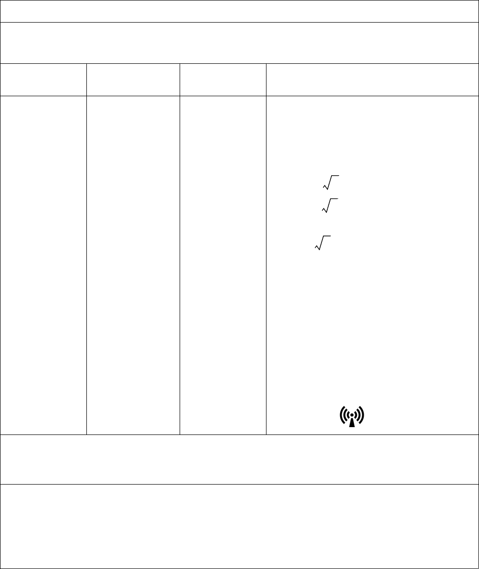
Guidance and Manufacturer’s Declaration - Electromagnetic Emissions
The MR200 is intended for use in the electromagnetic environment specified below, and the customer or the user
should assure that it is used in such an environment.
Emissions Test Compliance Electromagnetic Environment - Guidance
RF Emissions
CISPR 11
Group 1 The MR200 uses RF energy only for its internal functions.
Therefore, its RF emissions are very low and are not likely to
cause any interference in nearby electronic equipment.
RF Emissions
CISPR 11
Class B
The MR200 is suitable for use in all establishments, other than
domestic establishments and those directly connected to the
public low-voltage power supply network that supplies buildings
used for domestic purposes.
Harmonic Emissions
IEC 61000-3-2
Class B
Voltage Fluctuations/flicker
emissions
IEC 61000-3-3
Complies

ExpressionMR200InstructionsforUseImportantInformation1‐7
Guidance and Manufacturer’s Declaration - Electromagnetic Immunity
The MR200 is intended for use in the electromagnetic environment specified below. The customer or the user of the
MR200 should assure that it is used in such an environment.
Immunity
Test IEC 60601 Test Level Compliance Level Electromagnetic
Environment - Guidance
Electrostatic
discharge (ESD)
IEC 61000-4-2
± 6kV contact
± 8kV air
± 6kV contact
± 8kV air
Floors should be wood,
concrete or ceramic tile. If
floors are covered with
synthetic material, the
relative humidity should be at
least 30%.
Electrical fast
transient/burst
IEC 61000-4-4
± 2kV for power supply lines
± 1kV for input/output lines
± 2kV for power supply lines
± 1kV for input/output lines
Mains power quality should
be that of a typical
commercial or hospital
environment.
Surge
IEC 61000-4-5
± 1kV differential mode
± 2kV common mode
± 1kV differential mode
± 2kV common mode
Mains power quality should
be that of a typical
commercial or hospital
environment.
Voltage dips,
short
interruptions
and voltage
variations on
power supply
input lines
IEC 61000-4-11
< 5% Ut
(> 95% dip in Ut) for 0.5 cycle
40% Ut
(60% dip in Ut) for 5 cycles
70% Ut
(30% dip in Ut) for 25 cycles
< 5% Ut
(> 95% dip in Ut) for 5
seconds
< 5% Ut
(> 95% dip in Ut) for 0.5 cycle
40% Ut
(60% dip in Ut) for 5 cycles
70% Ut
(30% dip in Ut) for 25 cycles
< 5% Ut
(> 95% dip in Ut) for 5 seconds
Mains power quality should
be that of a typical
commercial or hospital
environment. If the user of
the MR200 requires
continued operation during
AC power interruptions,
power from an
uninterruptable power supply
or battery is recommended.
Power
frequency (50/
60 Hz)
magnetic field
IEC 61000-4-8
3 A/m 3 A/m Power frequency magnetic
fields should be at levels
characteristic of a typical
location in a typical
commercial or hospital
environment.
NOTE
Ut is the AC mains voltage prior to application of the test level.
1‐8ImportantInformationExpressionMR200InstructionsforUse
Guidance and Manufacturer’s Declaration - Electromagnetic Immunity
The MR200 is intended for use in the electromagnetic environment specified below. The customer or the user of the
MR200 should assure that it is used in such an environment.
Immunity Test IEC 60601 Test
Level
Compliance
Level Electromagnetic Environment - Guidance
Conducted RF
IEC 61000-4-6
Radiated RF
IEC 61000-4-3
3 Vrms
150 KHz to 80 MHz
3 V/m
80 MHz to 2.5 GHz
V1 = 3 Vrms
E1 = 3 V/m
Portable and mobile RF communications equipment
should not be used no closer to any part of the
MR200, including cables, than the recommended
separation distance calculated from the equation
applicable to the frequency of the transmitter.
Recommended separation distance
d = (3.5/V1)
d = (3.5/E1)
(80 MHz to 800 MHz)
d = (7/E1)
(800 MHz to 2.5 GHz)
Where P is the maximum output power rating of
the transmitter in watts (W) according to the
transmitter manufacturer and d is the recom-
mended separation distance in meters (m).
Field strengths from fixed RF transmitters, as
determined by an electromagnetic site survey,a
should be less than the compliance level in each
frequency range.b
Interference may occur in the vicinity of equipment
marked with the symbol.
• At 80 MHz and 800 MHz, the higher frequency range applies.
• These guidelines may not apply in all situations. Electromagnetic propagation is affected by absorption and
reflection from structures, objects and people.
a Field strengths from fixed transmitters, such as base stations for radio (cellular/cordless) telephones and land mobile radios,
amateur radio, AM and FM radio broadcast and TV broadcast cannot be predicted theoretically with accuracy. To assess the
electromagnetic environment due to fixed RF transmitters, an electromagnetic site survey should be considered. If the measured
field strength in the location in which the MR200 is used exceeds the applicable RF compliance level above, the MR200 should be
observed to ensure normal operation. If abnormal performance is observed, additional measures may be necessary, such as re-
orienting or relocating the MR200.
b Over the frequency range 150 KHz to 80 MHz, field strengths should be less than 3 V/m.
P
P
P

ExpressionMR200InstructionsforUseImportantInformation1‐9
Using Batteries Safely
Batterieshavelifecycles.Whentheequipmentoperatingtimeprovidedbybatterypower
becomesmuchshorterthanusual,thebatterylifeisatanend.Immediatelyremoveanybattery
thathasanexpiredlifecycleandreplaceitwithanewbatteryofthesametype.(Refertopage1‐
28forpartnumbers.)Toensurethesafetyofoperatorsandpatients,observethefollowing
warningsandcautions.
Warning
WARNING
Stop using any battery that exhibits abnormal heat, odor, color, deformation, or other
condition. If a battery is punctured or if battery liquid leaks onto your skin or clothing,
immediately wash the area and clothing with fresh water. If battery liquid gets into your
eyes, do not rub your eyes; immediately flush your eyes with clean water and consult a
physician.
Recommended Separation Distances between Portable and Mobile RF Communications
Equipment and the MR200
The MR200 is intended for use in an electromagnetic environment in which radiated RF disturbances are controlled.
The customer or the user of the MR200 can help prevent electromagnetic interference by maintaining a minimum
distance between portable and mobile RF communications equipment (transmitters) and the MR200 as
recommended below, according to the maximum output power of the communications equipment.
Rated Maximum Output
Power Of Transmitter
(W)
Separation Distance According To Frequency Of Transmitter (m)
150 KHz to 80 MHz
d = (3.5/V1)
80 MHz to 800 MHz
d = (3.5/E1)
800 MHz to 2.5 GHz
d = (7/E1)
0.01 0.117 0.117 0.233
0.1 0.369 0.369 0.738
1 1.167 1.167 2.333
10 3.689 3.689 7.379
100 11.667 11.667 23.333
For transmitters rated at a maximum output power not listed above, the recommended separation distance d in
meters (m) can be estimated using the equation applicable to the frequency of the transmitter, where P is the
maximum output power rating of the transmitter in watts (W) according to the transmitter manufacturer.
• At 80 MHz and 800 MHz, the separation distance for the higher frequency range applies.
• These guidelines may not apply in all situations. Electromagnetic propagation is affected by absorption and
reflection from structures, objects and people.
P
P
P
1‐10ImportantInformationExpressionMR200InstructionsforUse
Caution
CAUTIONS
• If the battery contacts become dirty, wipe them clean with a dry cloth before use.
• Store batteries in a dry place, between 0°C to 40°C.
• Keep metal objects away from the battery contacts.
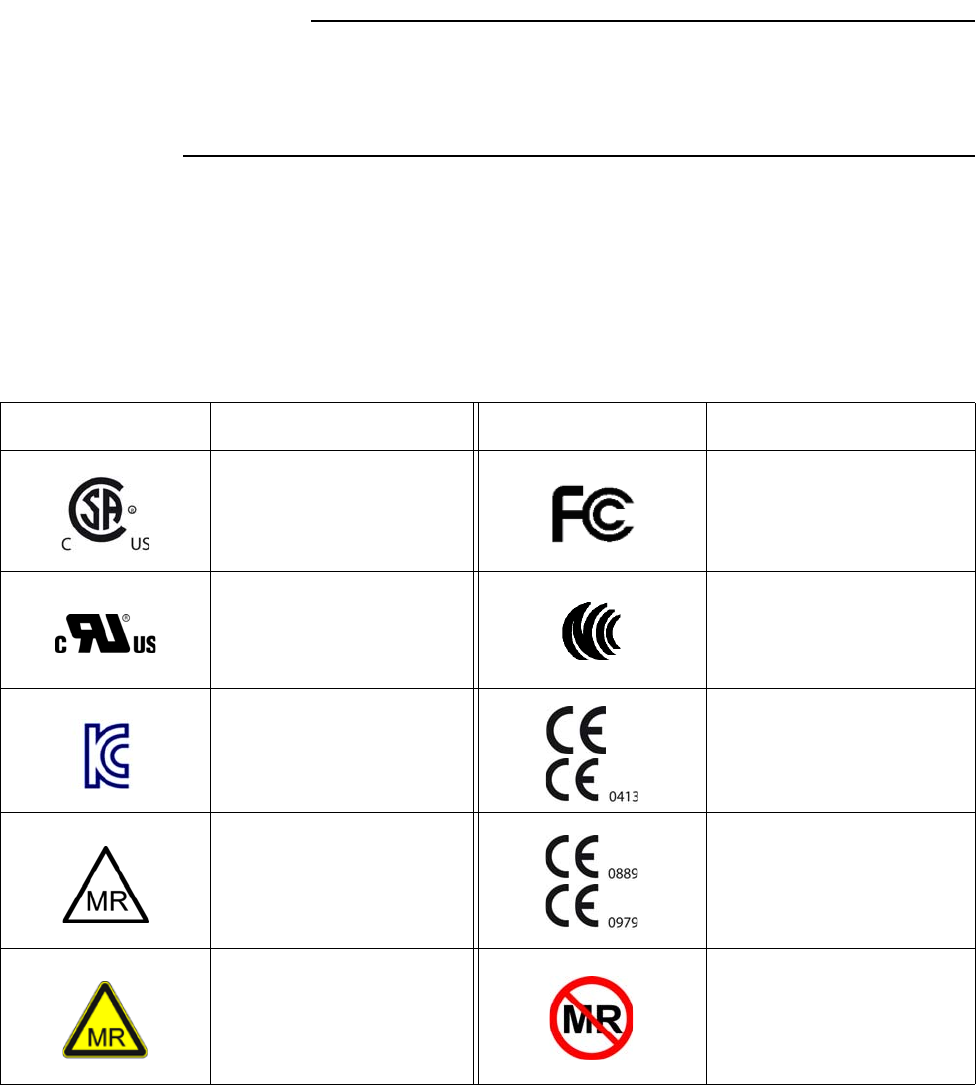
List of Symbols
ThesymbolsinthefollowingtablemayappearontheMR200,thepackingmaterials,orinthis
manual.
Symbol Meaning Symbol Meaning
CSA certified for both the
U.S. and Canadian markets
Federal Communications
Commission radio
certification
Underwriters Laboratories
Component Recognition
Mark for both the U.S. and
Canadian markets
Taiwan National
Communications Commission
certification
Korean Communications
Commission radio
certification
Conforms to the Medical
Device Directive
MR Conditional: Use in the
MR environment is restricted
to certain conditions of use
to ensure patient and
operator safety.
Conforms to the R&TTE
Directive (Radio &
Telecommunications
Terminal Equipment)
MR Conditional: Use in the
MR environment is restricted
to certain conditions of use
to ensure patient and
operator safety.
MR unsafe
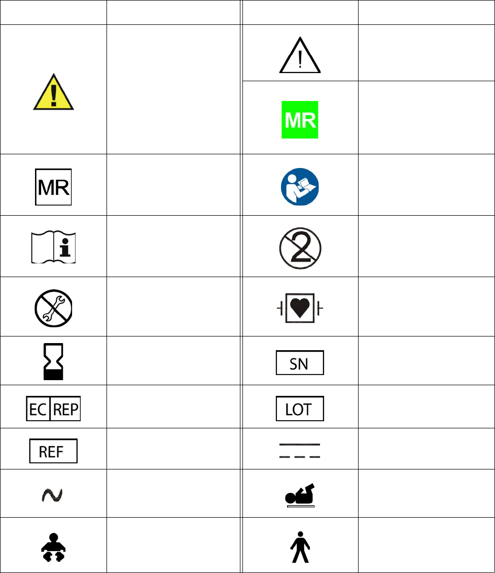
ExpressionMR200InstructionsforUseImportantInformation1‐11
Warning! Specific warnings
associated with the devices
that are not otherwise found
on the label; when located on
the wECG module
connector, indicates that only
specified ECG cables shall be
used to ensure safe use in the
MR and defibrillation
protection.
Caution! Specific warnings or
precautions associated with
the devices that are not
otherwise found on the label
MR safe
MR safe Mandatory action: Follow the
Instructions for Use
Consult the Instructions for
Use
Single use only, disposable
one-time-use product; do not
reuse
Do not adjust without
referring to the service
manual
Defibrillator-proof type CF
equipment (IEC 60601-1)
protection against shock
Use by date (do not use after
the year, month or day
shown)
Serial number
Authorized representative in
the European Community Batch code/lot number
Catalog, reorder or
reference part number Direct current
Alternating current Neonate
Infant Adult / Pediatric
Symbol Meaning Symbol Meaning
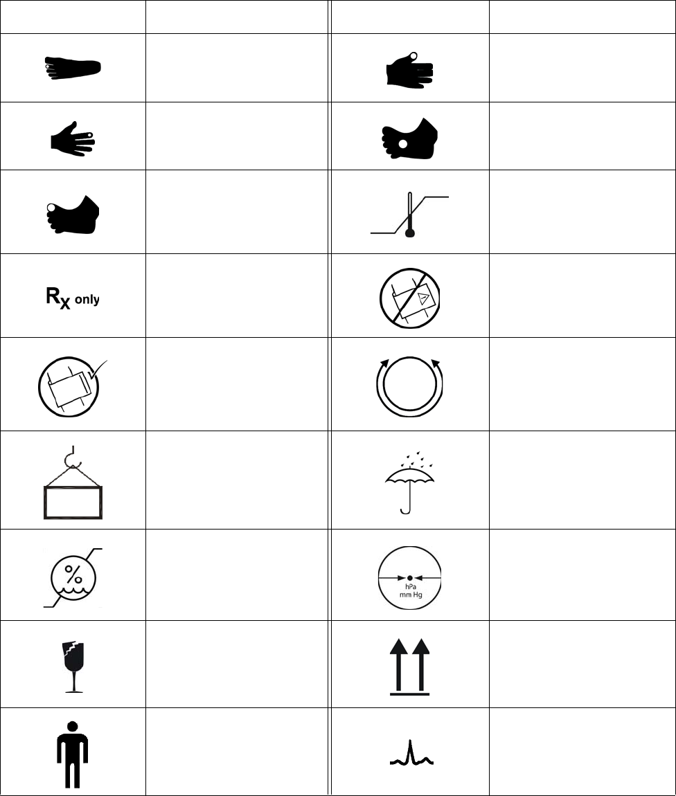
1‐12ImportantInformationExpressionMR200InstructionsforUse
Toe site Thumb site
Finger site Foot site
Toe site Temperature range
Prescription only NiBP cuff, wrong side out
NiBP cuff, correct side out NiBP cuff circumference
range
Weight Keep dry
Humidity range Atmospheric pressure
limitation
Fragile Up
Patient ECG
Symbol Meaning Symbol Meaning
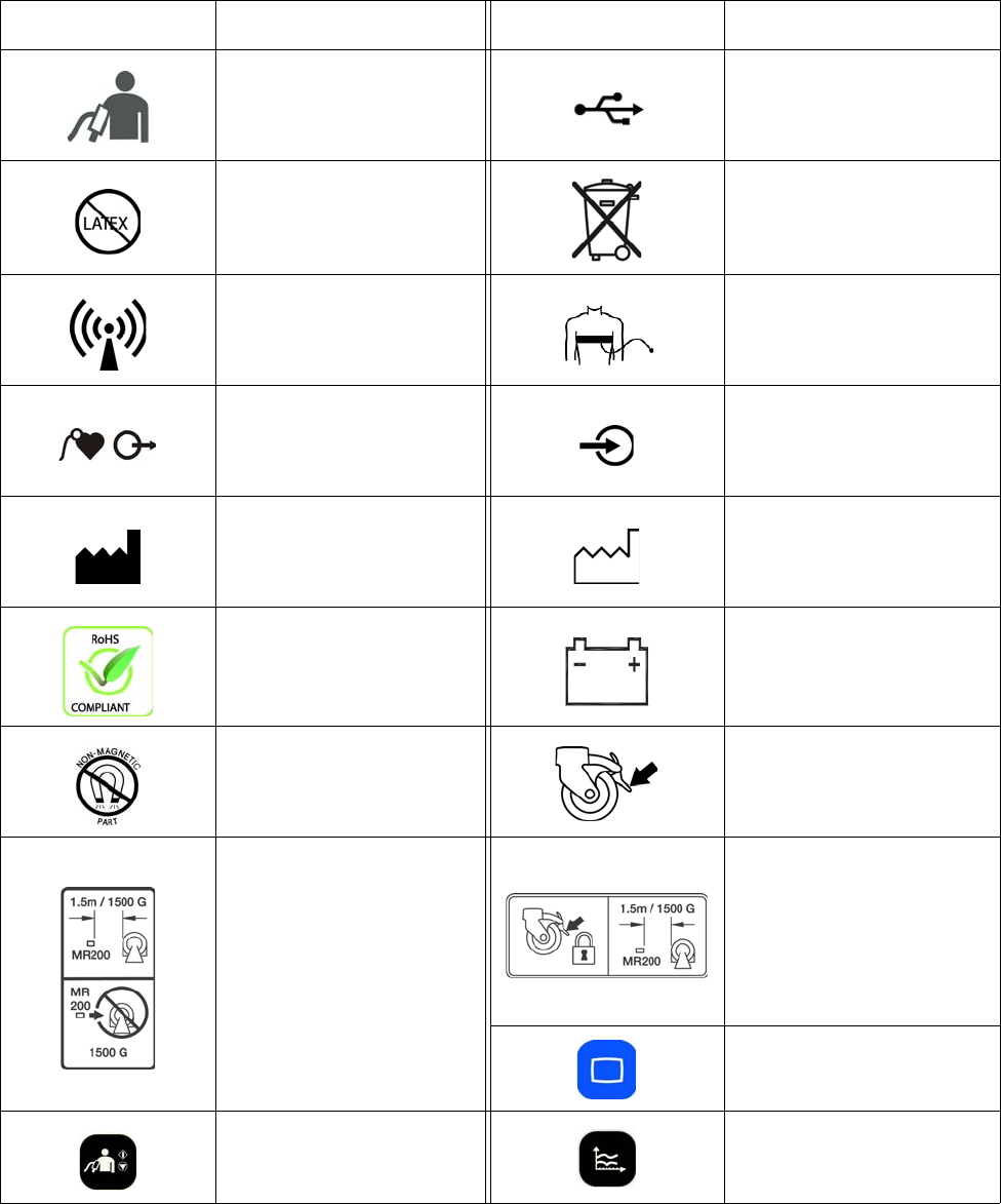
ExpressionMR200InstructionsforUseImportantInformation1‐13
Non-invasive blood pressure
(NiBP) Universal Serial Bus (USB)
Contains no latex
Dispose of the battery or
electronic waste in
accordance with your
country’s requirements
Non-ionizing radiation Pneumatic respiration
Cardiac gating output Input connection
Manufacturer name and
address information
Date of manufacture, YYYY-
MM
Conforms to the RoHS
directive Battery
Non-magnetic part Wheel lock, press to engage
Do not move the MR200
inside the 1,500 gauss field
line of the MR magnet or
within 1.5 m (4.9 feet),
whichever is greater, as
measured from the center
line of the bore.
Apply wheel locks and do not
move the MR200 inside the
1,500 gauss field line of the
MR magnet or within 1.5 m
(4.9 feet), whichever is
greater, as measured from
the center line of the bore.
Main key
NiBP key Trends key
Symbol Meaning Symbol Meaning
mp
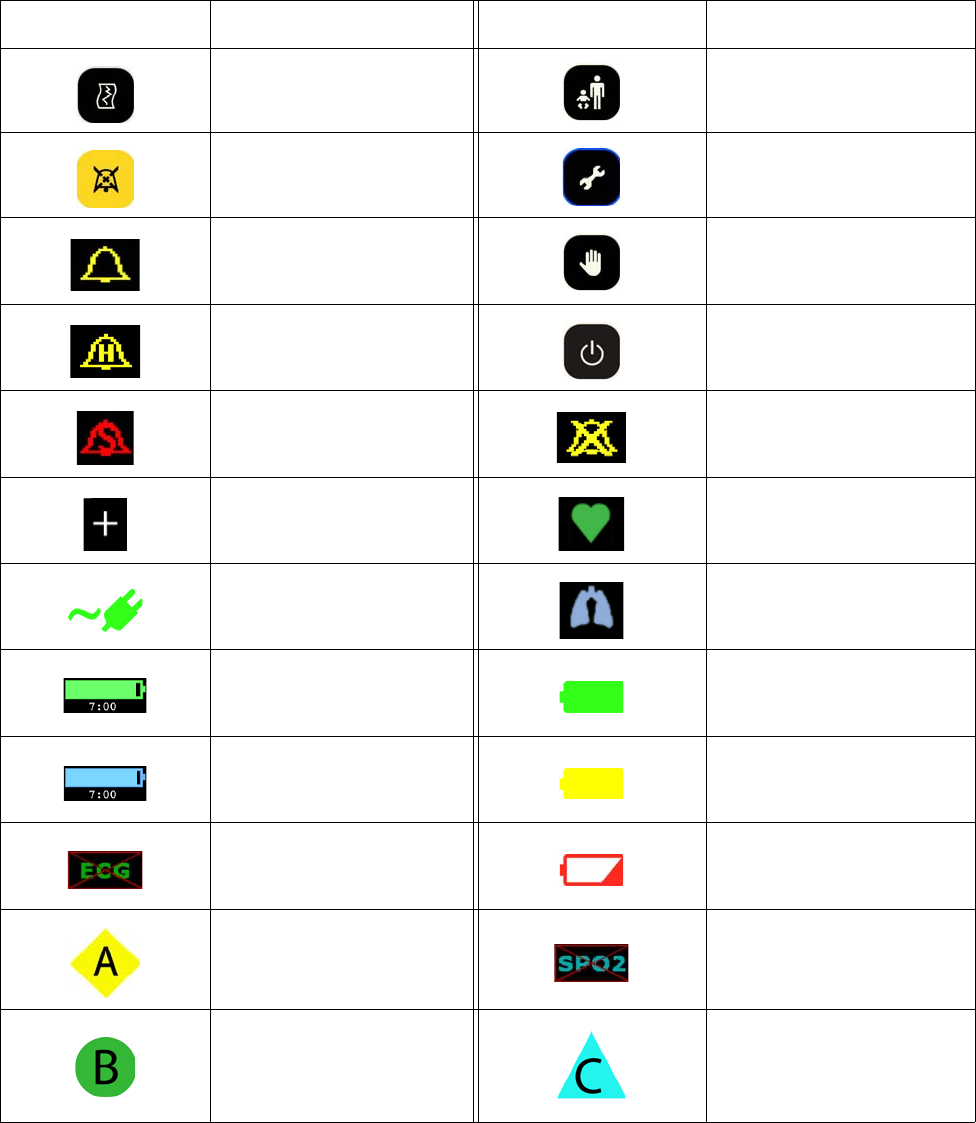
1‐14ImportantInformationExpressionMR200InstructionsforUse
Print key Patient key
Silence key Setup key
Alarm sound on Suspend key
Alarm sound on hold Power switch
Alarm sound silenced Alarm sound off
Current setups have changed Heartbeat detected
On AC power Breathing effort detected
wECG battery time
remaining Good battery power
wSPO2 battery time
remaining No AC, on battery power
No MR200 communication
with the wECG module Low battery power
Network channel A No MR200 communication
with the wSPO2 module
Network channel B Network channel C
Symbol Meaning Symbol Meaning
ExpressionMR200InstructionsforUseImportantInformation1‐15
Examining the Contents
Toreportshippingdamage,ortoresolveanyissuesorconcernswithyourorder,contact
CustomerService.(Saveallpackingmaterialsandrelatedshippingdocuments,asthesemaybe
requiredtoprocessashippingdamageclaimwiththecarrier.)
Afterremovingthecontentsfromtheshippingcontainers,carefullyexamineallitemsforsignsof
damagethatmayhaveoccurredduringshipment.Also,checkallitemsagainsttheincluded
packinglistandthepurchaserequest.
Thecontentsofthecrateshouldinclude:
• MR200
•Twocartbatteries
• InstructionsForUse(IFU)manual
•QuickReferenceGuide
•PowerCord
Aseparatecontainercouldincludeadditionalitems:
• WirelessECGmodule
• WirelessSPO2module
•Modulebatterycharger
•Modulebatteries
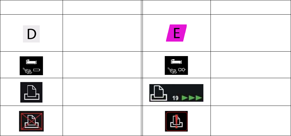
Network channel D Network channel E
Cart connected to AC mains,
batteries installed
Cart connected to AC mains,
batteries not installed
Printer ready Printing in progress and time
remaining, in seconds
No printer available Printer not ready
Symbol Meaning Symbol Meaning
1‐16ImportantInformationExpressionMR200InstructionsforUse
Assembly
Thissectionprovidesimportantinformationaboutassemblyandsystemrequirements.Observe
thewarningsandcautionsthatappearthroughoutthismanualwhenassemblingandusingthe
MR200.Forthelocationofcartcomponentsnotdetailedbelow,seetheillustrationonpage2‐3.
Warning
WARNING
Only perform assembly of the MR200 at a location outside of the MR magnet room. Failure
to observe this warning may result in serious injury.
CAUTION
The MR200 and accessories must be used and stored according to the environmental
specifications detailed in Appendix A. Failure to adhere to the specified environmental
requirements may affect system and/or accessory performance and accuracy.
Disposing of the Packaging
Thepackagingcanberetainedforfutureuse.Otherwise,thepackagingforthesystem(whichis
madeofrecyclablematerialsthatincludecorrugatedpaper,polyethylene[PE]foamandplastic)
maybesubjecttodisposalregulationsforuserandenvironmentalsafety.Fordisposal,itmaybe
necessarytoseparatethesematerialsbytype.Alwaysobserveandadheretoyourcurrentlocal
regulationswhendisposingofthepackagingmaterial.
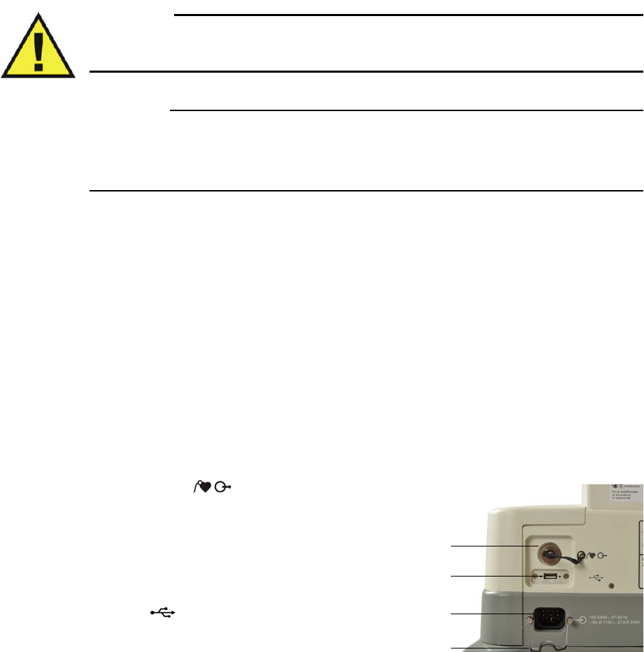
Rear Panel Connections
Hardwareinterfaceandpowerconnectionsareprovidedontherearpanelofthecart.
Gatingconnector
Presentsoutputsforgatingconnections
totheMRsystem.Removetheshield
capfromthegatingconnectorthen
installagatingcable.(Cablesaretype‐
dependant;seepage1‐26.)
USBport
AllowsUSBthumbdriveconnectionsfor
MR200softwareupdatesonly.(See
UpdatingSoftwareonpage11‐10.)
Gating connector
USB port
AC inlet
Strain relief
ExpressionMR200InstructionsforUseImportantInformation1‐17
ACInlet
IstheinputconnectionforACvoltagetothecart.
Strainrelief
SecurestheACpowercordtothecart.
Caution
CAUTIONS
• When making connections to the rear panel of the MR200, ensure that the final installation
complies with IEC/EN 60601-1-1, General Requirements for the Safety of Medical
Electrical Systems, to assure operator and patient safety. Always check the summation of
leakage currents when the MR200 is connected to additional external equipment.
• Where the integrity of the external protective conductor in the installation or its arrangement
is in doubt, the MR200 shall be operated from batteries.
Replacing Cart Batteries
Warning
WARNING
Cart batteries contain ferrous materials that are attracted to the MR magnetic field. Do not
install or remove the cart batteries when closer than the 1,000 gauss (0.1 T) field line, as
measured from the center line of the MR bore to the MR200. The batteries will be attracted
to the magnetic field, possibly causing patient or user injury.
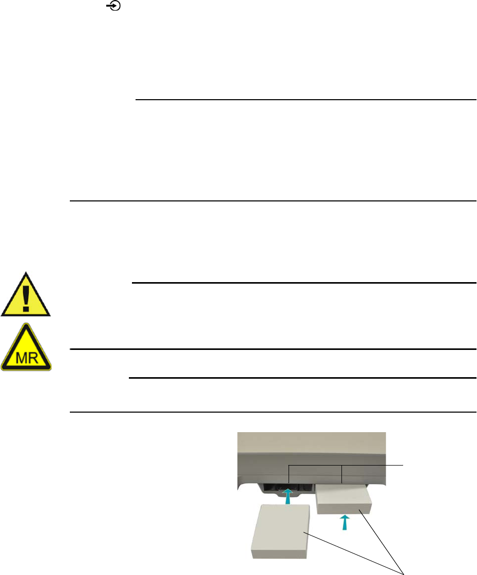
CAUTION
Never force a battery into a battery compartment as it will damage the battery and/or the cart.
Cartbatterieswillslideandlatchinto
placeinthebatterycompartmentsin
thebaseoftheunit:
•Wheninstallingbatteriesthey
mustbeorientedproperly,as
thebatteryshapeisdesignedto
fitthecontourofthebattery
compartment.
•Ifthebatterydoesnotlatch
intoplacewhenfullyinsertedin
thebatterycompartment,then
itisnotproperlyoriented.In
thiscase,removeandreorient
thebatterythenreinsertitintothebatterycompartment.
Battery
compartments
Cart batteries
1‐18ImportantInformationExpressionMR200InstructionsforUse
Toinstallcartbatteries
Orientabatteryforinsertion(labelsidedown,connectorfacingforward)thenslideitintoa
batterycompartment.Whenproperlyinserted,thebatterywilllatchintoplace.A“click”willbe
heardandthebatterywillbeflushwiththefaceofthebatterycompartment.Repeattheprocess
fortheremainingbattery.
NOTE
Before initial use, charge the batteries for at least 12 hours with the MR200 turned off and
connected to AC mains power.
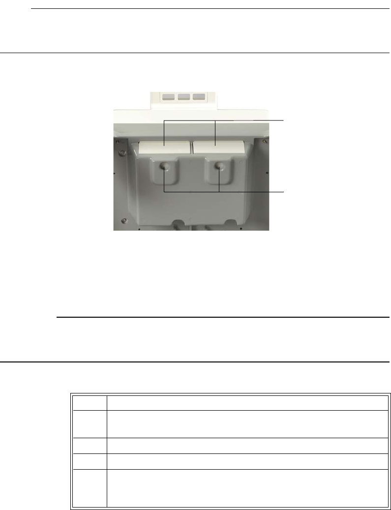
Toremoveacartbattery
Pressthebatteryeject
button(locatedonthe
undersideofthebattery
compartment).
(Ifthebatterydoesnot
release,applyaslight
forwardpressureonthe
batterywhilepressingthe
ejectbutton.)
Repeattheprocessto
removetheremaining
battery.
Connecting AC Mains Power
CAUTION
Avoid use of electrical extension cords or multiple portable socket outlets, which may create a
safety hazard by compromising the grounding integrity of the MR200.
ToconnectACmainspower
Cart batteries
Battery eject buttons
Step Action
1Ensurethatthecartbatteriesareinstalled;seepage1‐18for
details.
2PositiontheMR200;seepage2‐6.
3Raisethestrainrelief.
4ConnecttheACpowercordtotheACinletontheMR200.For
addedmobility,thepowercordextension(REF989803168221)can
alsobeconnected.
ExpressionMR200InstructionsforUseImportantInformation1‐19
ToremovetheMR200fromACmainspower
PullouttheplugatthewalloutletandthenremovetheACpowercordfromtheMR200.Store
thecordinasafeplace.
MR200 Battery Operation
Warning
WARNING
Do not touch the internal battery compartments of the cart and the patient simultaneously.
Cartbatteriesarechargedandconditionedbyanintegratedintelligentchargingsystem.When
turnedon,theMR200operatesfromACpowerandsimultaneouslychargesthebatteries.When
connectedtoACpowerandturnedoff,thebatterychargerremainsfunctionalandcharging
occursautomatically.IfACvoltageislost,theMR200willautomaticallyswitchtobatterypower
toprovideuninterruptedservice.
NOTES
• To prevent unintentional power interruptions, it’s highly recommended to always keep the
batteries inserted in the MR200 even when operating on AC power.
• If the MR200 will not be used for more than 3 days, remove the batteries or keep AC power
connected.
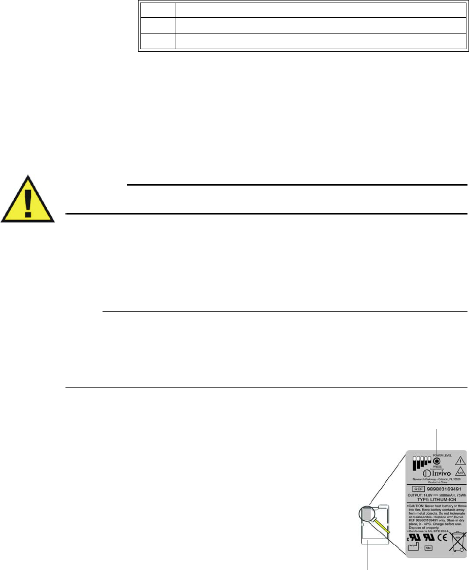
MaximumMR200operationtimeunderbatterypoweris
approximately8hours,butthismaybereducedbyupto2
hourswhencertainoperationsareperformed—suchasrunning
NiBPcyclesatlessthan5‐minuteintervals.
Visualindicationofthechargedcapacityisdisplayedbythe
cartstatusicon(seepage2‐16).
Chargedcapacitycanalsobeseenbypressingthepowerlevel
buttononeachcartbattery,wherethecapacityisindicatedin
20percentincrements.
5LowerthestrainreliefovertheACpowercord.
6ConnecttheACpowercordtoanapprovedACmainsoutlet.
Step Action
Power level button
Cart battery
1‐20ImportantInformationExpressionMR200InstructionsforUse
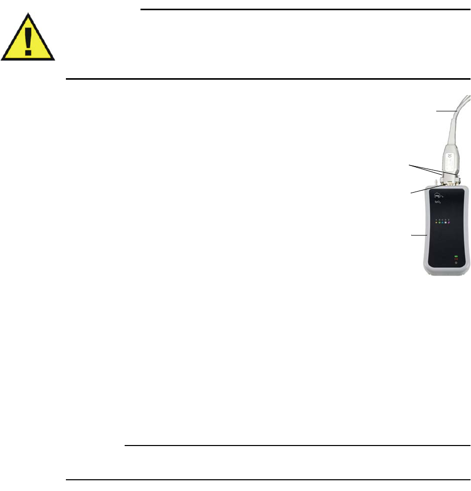
Attaching the SPO2 Sensor to the wSPO2 Module
WARNINGS
• Only perform this assembly at a location outside of the MR magnet room. Failure to
observe this warning may result in serious injury.
• Connecting other than specified SPO2 sensors to the wSPO2 module can cause
inaccurate SPO2 readings and damage the module.
ToattachtheSPO2sensortothewSPO2module
InserttheSPO2sensortotheDB‐9connectoronthewSPO2
module.Then,usingastandardscrewdriver,securelytighten
bothscrews.
Charging Module Batteries
Modulebatteriesarechargedinthemodulebatterycharger.Refertotheinstructionsprovided
withthemodulebatterychargerforplacementanduseinformation.
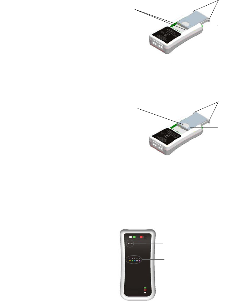
Replacing a Module Battery
Eachwirelessmodulehasslotslocatedonbackofthedevicetohousethebattery.Module
batteriesareinterchangeable,non‐magnetic,andcanbehandledintheMRmagnetroom.For
operationalinformationaboutthewirelessmodules,seepage2‐7.
CAUTION
To minimize the chance of image artifacts, never place module batteries in the MRI field of view.
SPO2 sensor
Screws
wSPO2 module
DB-9 connector
ExpressionMR200InstructionsforUseImportantInformation1‐21
Toinstallamodulebattery
Orientthebatteryasshownandthenslide
thebatterybetweentheslotsonbackof
themoduleuntilbothtabslatchinto
place.Storethemodulesinthemodule
holdersonthecart;see2‐5fordetails.
Toremoveamodulebattery
Usingthethumbandindexfingerofone
hand,pressthetabsinwardandhold.
Thenplacethethumborafingerofyour
otherhandontherecessandpushthe
batteryoutofthemodule.
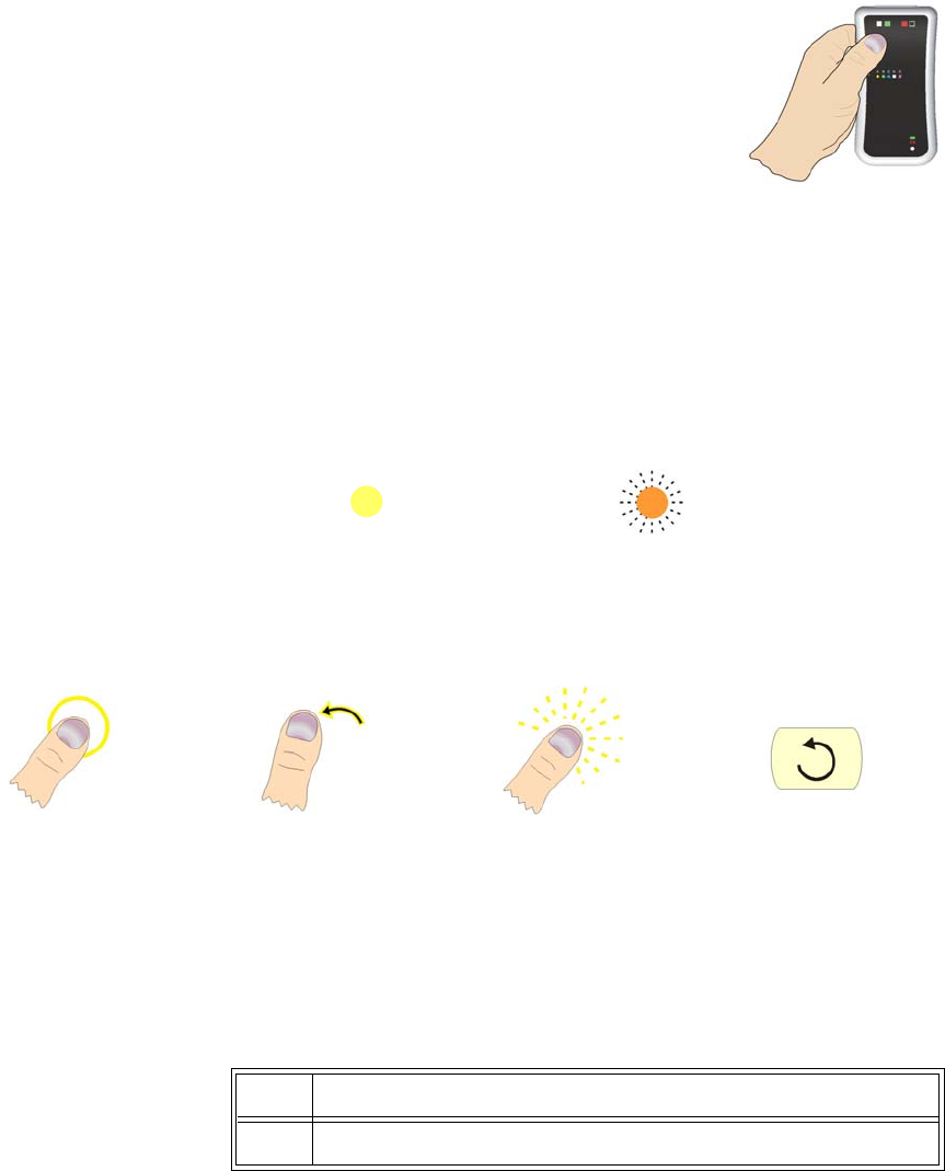
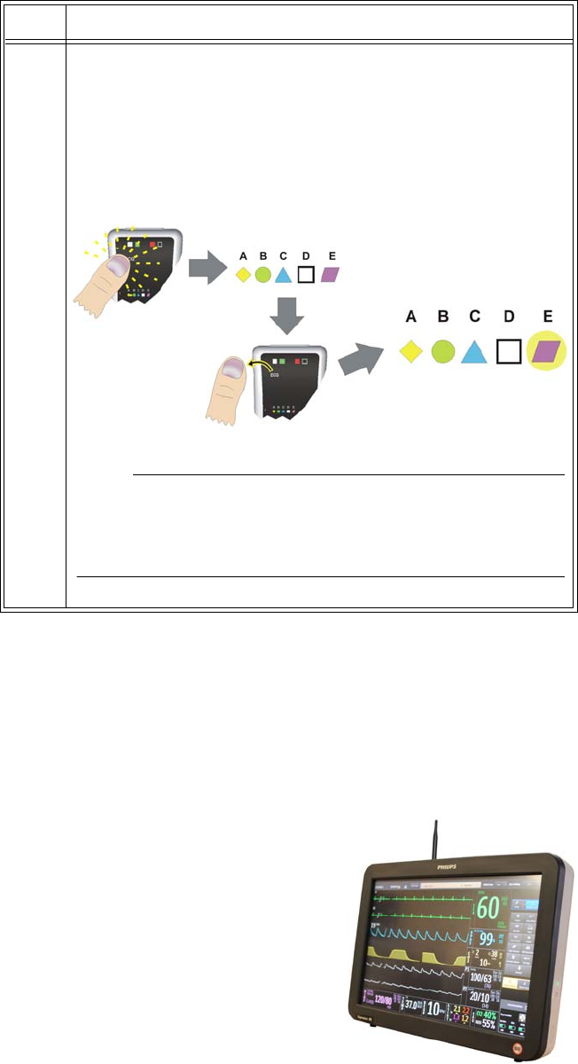
Assigning the Network Channel of a Module
NOTE
The modules for your system may arrive pre-programmed to match the network setting of the cart.
Inorderforamoduletocommunicatewith
theMR200,thewirelessnetworksettingof
eachmustbethesame.
Thecurrentsettingofamoduleis
indicatedbyitsilluminatednetworkicon.
Foreaseofrecognition,e
achnetworkicon
hasauniqueletter(A–E),shapeandcolor.
(ThesettingfortheMR200isdisplayedon
theLCD;seepage2‐16.)
Thewirelessnetworkchannelforthemoduleischangedbyusingthenetworkbuttonlocated
underneaththelabelinthefrontupperleftcornerofthedevice;seetheillustrationbelow.(You
willbeabletofeelaslightbumpwhenyoupassafingeroverthebuttonarea.)
Thefollowingdirectionsforchangingthenetworkchannelapplytobothwirelessmodules,
thoughtheprocessbelowdepictsonlythewECGmodule.
Battery
Module
Slots
Tabs
Battery
Tabs
Recess
Network icons
Button area
1‐22ImportantInformationExpressionMR200InstructionsforUse
Topressthenetworkbutton
Placethemoduleonaflatsteadysurface(orholdthemoduleasshownin
thefigure,right)andthenuseyourthumbtopressthenetworkbutton.
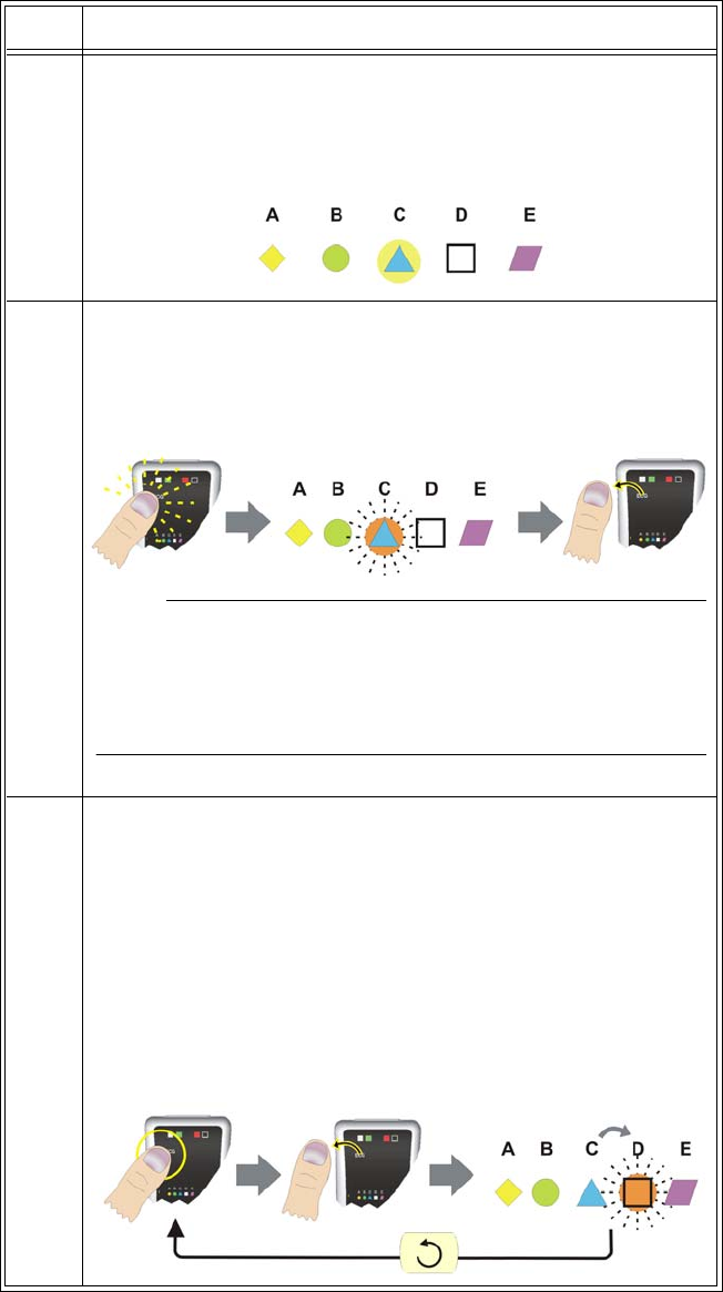
Changing the Network Channel of a Module
Beforestartingtheproceduretochangethenetworkchannelofthemodule,takenoteofthese
conventionsthatareusedtoexplaintheprocess:
•Intheprocedurebelow,thefollowingsymbolsareusedtoconveythestateofthenetwork
icononawirelessmodule.
.
•Intheprocedurebelow,thefollowingillustrationsareusedtoconveyactionsconcerning
theuseofthenetworkbutton.
Tochangethenetworkchannelofawirelessmodule
Iconilluminated Iconblinking
Pressingthe
button
Releasingthe
button
Pressingandholding
thebutton Repeating
Step Action
1Turnoffthemodulebyremovingthebattery;seepage1‐21.
ExpressionMR200InstructionsforUseImportantInformation1‐23
2Insertabatteryintothemodule;seepage1‐21.
Thenetworkiconswillflashbrieflyandthenthecurrentnetwork
iconwillilluminate(forexample,“C”intheillustrationbelow).
3 Enterthenetworkchangemode:Afterthecurrentnetworkicon
hasbeenilluminated(andwithin15secondsfrommodulepower‐
up)pressandholdthenetworkbuttonuntilthecurrentnetwork
iconbeginstorapidlyblinkthenreleasethebutton.
NOTE
If the network change sequence was not started within 15 seconds
after the module has been turned on, network changes will not be
allowed. In this case, you must cycle module power and restart the
sequence.
4Pressdownagainonthebuttonuntiltheiconstopsblinkingand
thenreleasethebuttontochangethenetworksetting.
Whenyoudothis,thenextnetworkiconinthesequencewillblink
rapidly.(Inotherwords,ifthemodulewasoriginallyusingnetwork
“C,”nowthe“D”iconwillbeblinking.)Repeatthissequenceof
pressingdownandreleasingthebuttonuntiltheiconofthe
networkyoupreferisrapidlyblinking.Ifyoupassthedesired
network,simplycontinuepressingandreleasingthebuttonuntil
thedesirednetworkisblinkingagain.
Step Action
1‐24ImportantInformationExpressionMR200InstructionsforUse
Advanced User Options
Expression Information Portal (Model IP5)
ProvidingsystemcontroloutsidetheMRmagnetroom,the
ExpressionInformationPortal(ModelIP5),hereafterreferred
toastheIP5,isawirelessdevicethatalsofeaturesprinting
capabilitiesandHL7dataoutputoptions.
5Whenyoureachthedesiredicon,pressandholdthebuttonfor
approximately5secondstolockandsavethenewsetting.
Theselectednetwork'siconwillturnoffwhilethebuttonis
depressed.Thenitwillilluminate(notblink)whenthenewnetwork
settingissaved.Onceilluminated,releasethebutton.Themodule
willbeginusingtheselectednetworkchannel.
NOTE
Any part the network change sequence not completed will cause the
module to revert to the network previously set 30 seconds after the
network button was last released.
Step Action

ExpressionMR200InstructionsforUseImportantInformation1‐25
Additional Options
Additionaloptions,suchasthoselistedbelow,maybesuggestedbyyourbiomedicaltechnician
toincreaseuserease.TheMR200isconfiguredwithinput/outputportstopermittheconnection
ofexternalequipment,including:
• Facilityinformationsystems
•GatingsourceforMRIfunctions
•USBportforsoftwareinstallation
Consultyourbiomedicaltechnicianortechnicalsupportwithspecificrequests.
Caution
CAUTIONS
• When adding equipment to an MR200 system (for example, an IP5), be aware that all
devices should be at the same or a compatible software revision level. Contact technical
support if you have questions or to upgrade software. Failure to observe this requirement
could result in compatibility conflicts, communication problems, etc.
• The manufacturer is not responsible for any radio frequency interference caused by
unauthorized modifications to the radios and/or antennas within this equipment. Such
modification could inhibit proper MR200 system or device communications.
Accessory List
Accessoriesarelistedinthetablesbelowwithpartnumber(REF)information.
CAUTION
The MR200 has been validated with all of the accessories listed below. Only use these specified
accessories as other types or brands may compromise the safety and accuracy of the MR200.
CO2 REF
LOFLO SAMPLE LINE, ADULT CANNULA, BOX 20 989803183241
LOFLO SAMPLE LINE, PED. CANNULA, BOX 20 989803183251
LOFLO SAMPLE LINE, NEO. CANNULA, BOX 20 989803183261
LOFLO LINE, ADU DVD CANNULA,BOX 20 989803183271
LOFLO LINE, PED DVD CANNULA, BOX 20 989803183281
LOFLO LINE, ADU AIRWAY ADPT, BOX 20 989803183291

1‐26ImportantInformationExpressionMR200InstructionsforUse
LOFLO SAMPLE LINE, ADULT CANNULA,BOX 100 989803185331
LOFLO SAMPLE LINE, PED CANNULA, BOX 100 989803185341
LOFLO SAMPLE LINE, NEO CANNULA, BOX 100 989803185351
LOFLO LINE, ADU DVD CANNULA, BOX 100 989803185361
LOFLO LINE, PED DVD CANNULA, BOX 100 989803185371
LOFLO LINE ADU AIRWAY ADPT, BOX 100 989803185381
ECG REF
GEL, ECG/EEG, SKIN PREP, TUBE, 3-PACK 989803152291
CAB, 4 LD, MRI ECG 989803152301
CAB, 4 LD, NEO.MRI ECG 989803152331
CAB, 4 LD, CV MRI ECG 989803152351
ADVANCED APPS ECG CABLE 989803176381
ADVANCED FILTER ECG CABLE 989803170121
QUADTRODE MRI ECG PAD, 25/BOX 989803179031
ELCTRD, MRI ECG, QUTRD.CV, 25/BOX 989803179041
ELCTRD, MRI, NEO.QUDTRD, 25/BOX 989803179051
WIRELESS ECG PATIENT MODULE 989803183661
CAB, 4 LD, NEO.MRI ECG, IEC 989803185441
CAB, 4 LD, CV MRI ECG, IEC 989803185451
CAB, 4 LD, MRI ECG, IEC 989803185461
ADVANCED FILTER ECG, IEC 989803185471
ADVANCED APPS ECG CABLE, IEC 989803185481
Gating Cables REF
CAB, DIGITAL GATING, GE, 3160 989803152821
CAB, GATING, SIEMENS, 3160 989803152831
CAB, GATING, PHILIPS ACH, 3160 989803152841
CAB, DIG.GATING, HIT/TOSH, 3160 989803152851
CO2 REF

ExpressionMR200InstructionsforUseImportantInformation1‐27
Non-invasive Blood Pressure REF
NIBP CUFF, SINGLE LUMEN, INFANT 989803182611
NIBP CUFF, SINGLE LUMEN, PEDIATRIC 989803182621
NIBP CUFF, SINGLE LUMEN, SMALL ADULT 989803182631
NIBP CUFF, SINGLE LUMEN, ADULT 989803182641
NIBP CUFF, SINGLE LUMEN, ADULT-L 989803182651
NIBP CUFF, SINGLE LUMEN, LRG ADULT 989803182661
NIBP CUFF, SINGLE LUMEN, LRG ADULT-L 989803182671
NIBP CUFF, SINGLE LUMEN, THIGH 989803182681
NIBP CUFF, SINGLE LUMEN, INFANT, DISP 989803182511
NIBP CUFF, SINGLE LUMEN, PEDIATRIC, DISP 989803182521
NIBP CUFF, SINGLE LUMEN,SMALL ADULT,DISP 989803182531
NIBP CUFF, SINGLE LUMEN, ADULT, DISP 989803182541
NIBP CUFF, SINGLE LUMEN, ADULT-L, DISP 989803182551
NIBP CUFF, SINGLE LUMEN, LRG ADULT, DISP 989803182561
NIBP CUFF, SINGLE LUMEN,LRG ADULT-L,DISP 989803182571
NIBP CUFF, SINGLE LUMEN, THIGH, DISP 989803182581
NIBP CUFF, SINGLE LUMEN, SAMPLE KIT,DISP 989803182591
NIBP CUFF, SINGLE LUMEN, NEO #1, DISP 989803183171
NIBP CUFF, SINGLE LUMEN, NEO #2, DISP 989803183181
NIBP CUFF, SINGLE LUMEN, NEO #3, DISP 989803183191
NIBP CUFF, SINGLE LUMEN, NEO #4, DISP 989803183201
NIBP CUFF, SINGLE LUMEN, INFANT #5, DISP 989803183211
ADULT PRESSURE INTERCONNECT HOSE 989803183221
NEONATAL PRESSURE INTERCONNECT HOSE 989803183231
Pneumatic Respiration REF
PNEUMOGRAPH,CHEST,NM,3160 989803152791

1‐28ImportantInformationExpressionMR200InstructionsforUse
Power REF
EUROPEAN LINE CORD 453564177501
NORTH AMERICAN LINE CORD 989803168211
CORD, JUMPER, 25 FEET 989803168221
BRAZILIAN POWER CORD, 3 METER 989803173901
UK LINE CORD, 3 METER 989803174171
POWER CORD, AUS/NZL, 3 METER 989803181291
POWER CORD, S AFRICA, 3 METER 989803181321
POWER CORD, DANISH, 3 METER 989803181331
POWER CORD, ISRAELI, 3 METER 989803181341
POWER CORD, ARGENTINA, 3 METER 989803181351
POWER CORD, SWISS, 3 METER 989803181361
SPO2 REF
QUICK CONNECT SPO2 PROBE, MRI 989803161991
QUICK CONNECT SPO2 CLIP, ADULT 989803166531
QUICK CONNECT SPO2 CLIP, PEDIATRIC 989803166541
QUICK CONNECT SPO2 GRIP, ADULT, 20/BOX 989803166551
QUICK CONNECT SPO2 GRIP, PED, 20/BOX 989803166561
QUICK CONNECT SPO2 GRIP, INFANT, 20/BOX 989803166571
QUICK CONNECT SPO2 GRIP, NEO, 20/BOX 989803166581
WIRELESS SPO2 PATIENT MODULE 989803183541
System REF
ASSY, 3.7V BATTERY CHARGER, 3160 989803152891
BATT.3.7V,WRLS.PAT.MDLE 989803152881
BATTERY, MRI, 14.8V, 5.08 AH, UL 989803169491
HANDLE HOOK, HOSE MANAGEMENT 989803185121
EXPRESSION INFORMATION PORTAL (IP5) 865471

ExpressionMR200InstructionsforUseImportantInformation1‐29
Miscellaneous REF
PAPER, THERMAL ARRAY, BLK, 50MM, OMNI MP05
QUICK REFERENCE GUIDE, MR200 453564357851
MANUAL, SERVICE, MR200 989803181911
MANUAL, OPERATORS, MR200, ENGLISH 989803184961
MANUAL, OPERATOR, MR200, DANISH 989803181971
MANUAL, OPERATOR, MR200, DUTCH 989803181981
MANUAL, OPERATOR, MR200, FINNISH 989803181991
MANUAL, OPERATOR, MR200, FRENCH 989803182001
MANUAL, OPERATOR, MR200, GERMAN 989803182011
MANUAL, OPERATOR, MR200, ITALIAN 989803182041
MANUAL, OPERATOR, MR200, NORWEGIAN 989803182051
MANUAL, OPERATOR, MR200, POLISH 989803182061
MANUAL, OPERATOR, MR200, PORTUGUESE 989803182071
MANUAL, OPERATOR, MR200, SPANISH 989803182091
MANUAL, OPERATOR, MR200, SWEDISH 989803182101
MANUAL, OPERATOR, MR200, TURKISH 989803182111
MANUAL, OPERATOR, MR200, JAPANESE 989803190941
MANUAL, OPERATOR, MR200, RUSSIAN 989803190951
MANUAL, OPERATOR, MR200, KOREAN 989803191221
MANUAL, OPERATOR, MR200, TRADITIONAL 989803191231
MANUAL, OPERATOR, MR200, INDONESIA 989803191351
1‐30ImportantInformationExpressionMR200InstructionsforUse
ExpressionMR200InstructionsforUseSystemOverview2‐1
CHAPTER 2
System Overview
FamiliarizeyourselfwiththeMR200anditscomponents.TheMR200combineswireless
communications,radiofrequencyshieldinganddigitalsignalprocessingtechnologiestoprovide
accurate,continuousandreliablepatientmonitoringperformanceinthedynamicmagnetic
resonanceenvironment.
ThemonitoringcapabilitiesoftheMR200canbeconfiguredtomeettheneedsofawide
spectrumofpatientsfromneonatetoadult.Everyparametercanbeaccessedandadjustedfor
theuniqueconditionofeachpatient.TheMR200accommodatesspecificmonitoringneeds,
including:
•Adult,pediatricandneonatalpatients
•Criticallyillpatients
•Patientundergoingsedation
•PatienttransportwithintheMRenvironment
• Interventionalprocedures
•Cardiacgating
System Components
AcompleteMR200systemconsistsofthefollowingcomponents:
•Cart
• WirelessECGmodule
• WirelessSPO2module
•Modulebatterycharger
• Batteriesandotheraccessoriesasneeded
•OptionalIP5andprinter
Use Model
Asillustratedbelow,theMR200isintendedtobeusedtomonitorthevitalsignsofapatientinan
MRmagnetroom.WhenpairedwiththeoptionalIP5,monitoringcapabilitycanbeextendedtoan
MRcontrolroom,inductionroom,orrecoveryroomenvironmentandthegathereddatacanbe
outputtoastripchartprinterorhospitalinformationsystem(HIS).
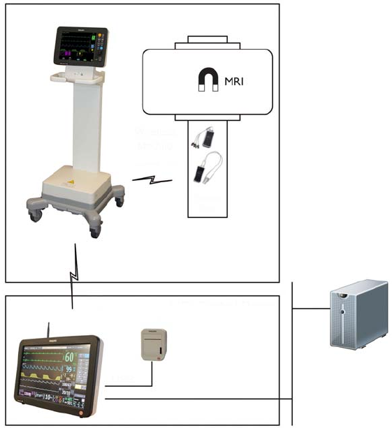
2‐2SystemOverviewExpressionMR200InstructionsforUse
Acquisition and Control
TheuseoftheMR200isrestrictedtoonepatientatatime.TheMR200displayspatient
measurementsacquiredduringmonitoring.Controlsandsettingsforpatientmonitoringare
providedlocallyatthedisplaypanelorremotely(forexample,intheMRIcontrolroom)when
equippedwiththeIP5,whereconnectionsfortheprinterandthehospitalnetworkarealso
available.
Synchronization
TheMR200willautomaticallyestablishcommunicationwiththewirelessmodulesandIP5(if
equipped).However,duetotheusemodel,thedevicescanestablishcommunicationand
synchronizepower‐onsettingsdependinguponthestart‐upsequence:
•IftheMR200bootsfirst,thenitssettingswillbereflectedattheIP5.
•IftheIP5bootsfirst,thenitssettingswillbereflectedattheMR200.
IfusinganIP5,patientidentifiableinformation(name,IDnumber,etc.)willbeavailableafter
synchronizationoccurs.
MR200
IP5
Hospital network
HIS system
MRI magnet room
MRI control room
Patient
bed
MR200 to IP5 (wireless)
Modules to
MR200
(wireless)
USB
Ethernet
Printer

ExpressionMR200InstructionsforUseSystemOverview2‐3
WARNING
The use model specifies one IP5 per MR200 system. If more than one IP5 is present on the
MR200 system, there is an increased risk of units within the system not synchronizing and
displaying incorrect or corrupted settings.
CAUTION
If the monitor’s settings are adjusted since they were last recalled or stored (manually, or via
synchronization - if using an IP5 ), the current setup name (see page 2-14) will be appended with a
plus symbol (+). The symbol will only be removed if the current settings are saved (see page 3-5)
or if different settings are recalled (see page 3-4). Always confirm the proper settings for the
MR200 and IP5 to ensure expected monitoring functionality.
NOTE
See DEFAULT SETUPS (on page 3-13) for information about power-on settings.
Device Control
Menucommandsthatcontroltheparameterfunctionsforpatientmonitoringaresynchronized
betweentheMR200andIP5.Commandsthatdonotdirectlycontrolthepatientparameters(for
example,printerfunctions)willonlyaffectIP5.OthercontrolsettingsremainlocalizedtotheIP5
andarenotsynchronizedwiththeMR200,includingalarmsilenceandholdfunctionsandvolume
settings(foracompletelisting,seetheIP5IFU).
Cart
DesignedforuseintheMRmagnetroomandthroughouttheMRsuite,thecartisawheeled
patientmonitorwithintegratedprocessing,power,displayandcontrolassemblies.Asillustrated
below,thisself‐containedmobilesystemalsoincludesstoragesolutionsforaccessories.
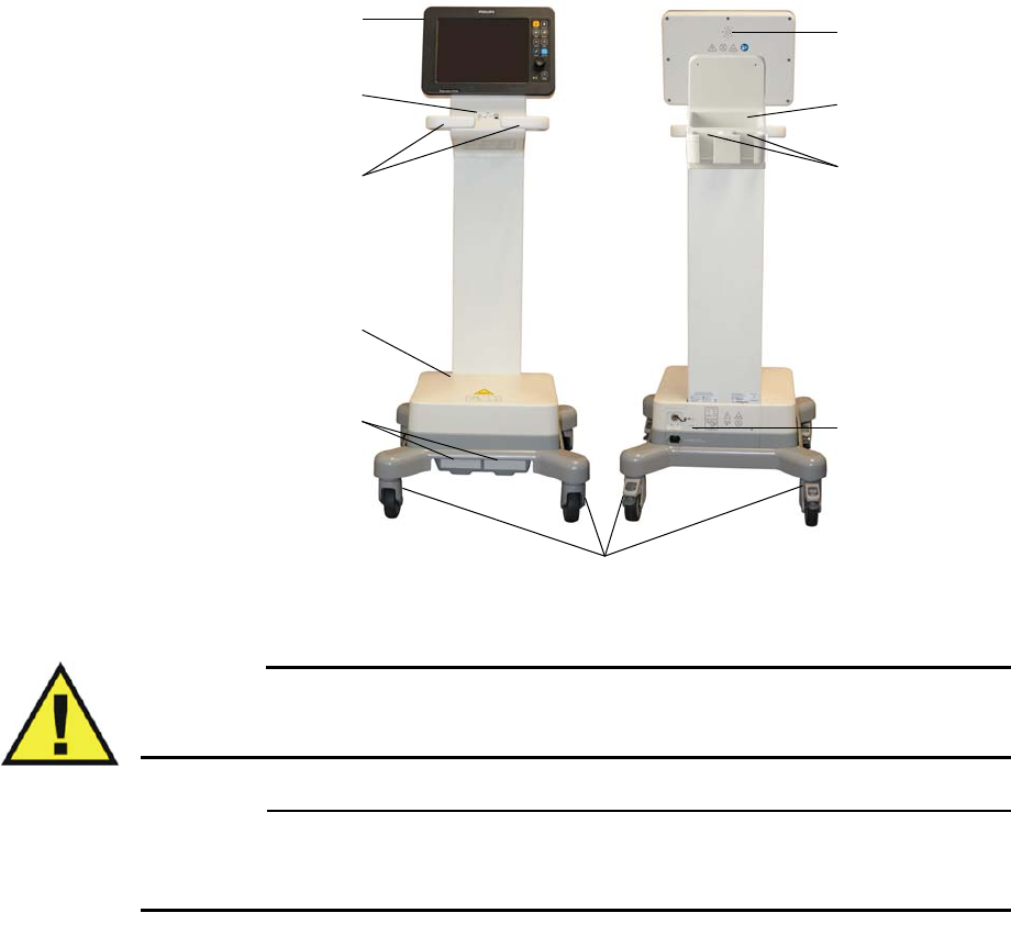
2‐4SystemOverviewExpressionMR200InstructionsforUse
WARNING
Never store ferrous items on the cart or in the storage basket. Failure to observe this
warning may result in serious injury.
CAUTION
Do not place more than 4 pounds (1.8 kg) of combined weight in the storage basket, module
holders and on the optional hose management handle hooks (not shown).
Speaker
Thespeakercommunicatesallaudiblesignals;seeSOUNDADJUSTonpage3‐8fordetails.
Storage Basket
ThestoragebasketprovidesconvenientplacementforCO2cannulas,NiBPcuffs,SPO2
attachmentsandQuadtrodeelectrodes.
Patient connection panel
Wireless processing unit
Battery compartments
Guide handles
Wheel locks
Speaker
Module holders
Rear panel
Storage basket
Display and control assembly
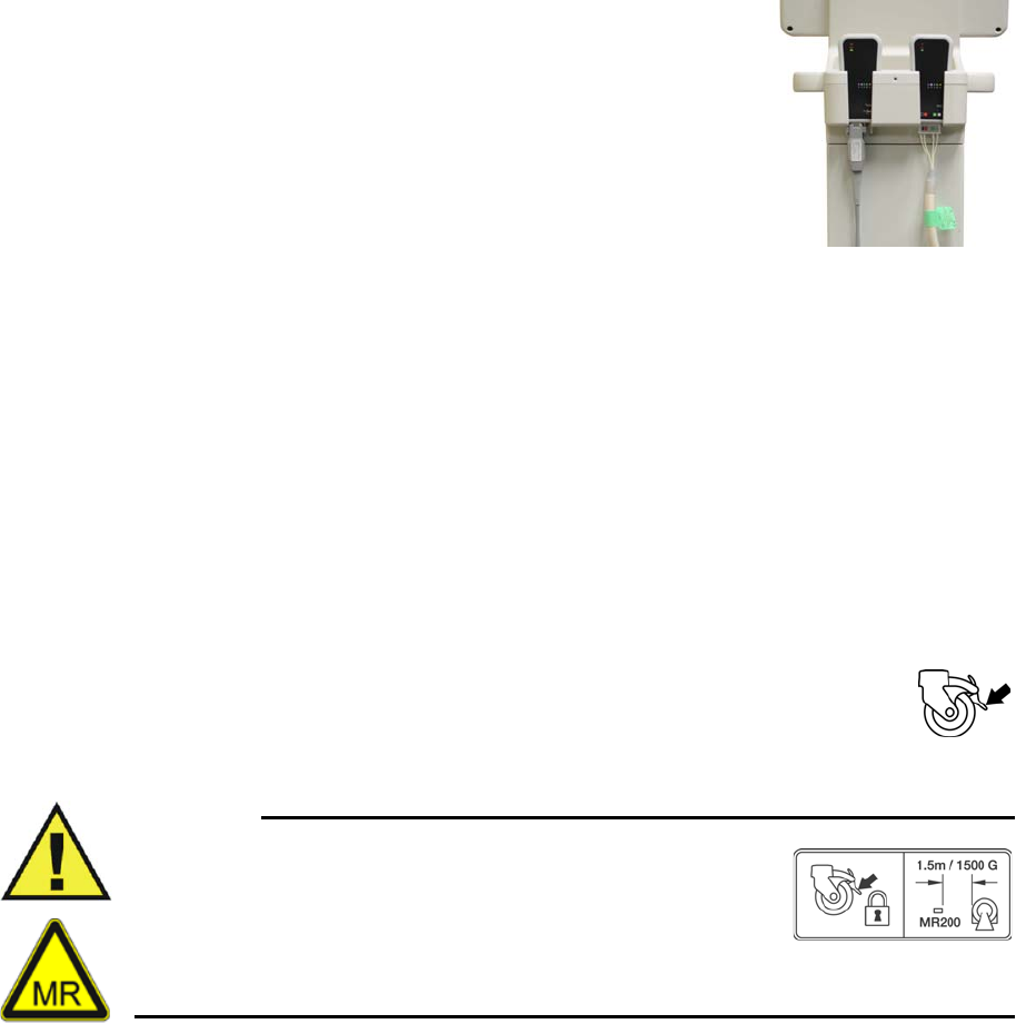
ExpressionMR200InstructionsforUseSystemOverview2‐5
Module Holders
Themoduleholdersprovidesafestorageforthewirelessmodules.
Placeawirelessmoduleinamoduleholdersothataconnected
accessoryhangsdownwardthroughtheopening.
Wireless Processing Unit
Thewirelessprocessingunit(WPU)housesthecommunication,processingandpowersystems
fortheMR200.
Rear Panel
TherearpanelcontainstheACinlet,gatingconnectorandUSBport;seepage1‐16fordetails.
Wheel Locks
Locksareprovidedoneachwheeltopreventmovementofthecart.Duringusein
theMRmagnetroom,stationthecartatasafemonitoringdistancethenpressdown
oneachwheellocktoengageit.Whenthecartneedstobemoved,raiseeachwheel
lockbeforeproceeding.(Seepage2‐6forpositioningdetails.)
WARNING
Do not move the MR200 inside the 1,500 gauss field line of the MR
magnet or within 1.5 m (4.9 feet), whichever is greater, as
measured from the center line of the bore. Always secure the
wheel locks when the MR200 is located in the MR magnet room.
Failure to properly place the MR200 in the MR magnet room will
result in monitoring system failure, and possible patient or user injury.
Battery Compartments
Thebatterycompartmentshousethecartbatteries;seepage1‐17details.
Guide Handles
Theguidehandlesprovidethemeansforpositioningthecart.
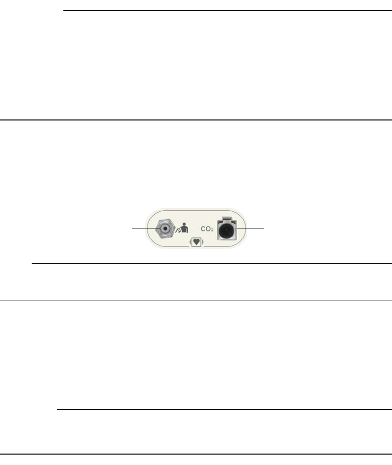
2‐6SystemOverviewExpressionMR200InstructionsforUse
CAUTIONS
• Never apply excessive force, lean against, stack or drape objects over the guide handles;
instead, use specially designed hose management handle hooks; see page 1-28 for details.
• If the MR200 rolls to the face of the MR system due to magnetically induced pull force, Do
not attempt to dislodge the MR200 by pulling from the display panel or guide handles;
instead, dislodge the MR200 by gently pulling from the lowest point of the base. This will
prevent the base of the unit from experiencing higher MR pull forces in the vertical
direction.
Patient Connection Panel
ThepatientconnectionpanelcontainsportsfortheNiBPandCO2attachments.
NOTE
Depending upon the equipped options, your MR200 may not have all indicated connections.
Display and Control Assembly
Thedisplayandcontrolassemblyhousesthedisplaypanelandspeaker,whichprovideuser
informationandsystemcontrol;seepage2‐10fordetails.
CAUTION
Never use the display and control assembly to position the cart; severe damage or failure can
result. Only use the guide handles and, if necessary, the storage basket to position the cart.
Positioning the MR200
Usetheguidehandlestomoveandpositionthecart.Alwayspositionthecartsothatyourview
oftheLCDremainsunobstructedduringuse.
TheMR200hasaninternalgausssensorwhich,incloseproximitytotheMRmagnet,
automaticallyshutsdownNiBPandCO2monitoringfunctions.Toalertyoutomovethecartaway
whenitistooclosetotheMRmagnet,theMR200willdisplaythefollowingwarningdialogbox
message:
Movemonitorawayfrommagnet.NiBPandCO2(ifinstalled)havebeenshutdown.
NiBP port CO2 port
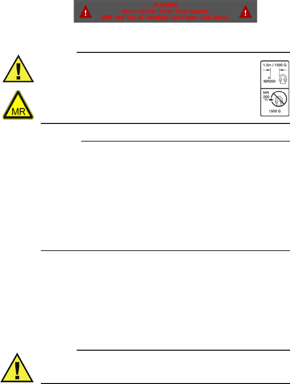
ExpressionMR200InstructionsforUseSystemOverview2‐7
WhenpositioningtheMR200foruse,observethewarningandcautionsbelow.
WARNING
Do not move the MR200 inside the 1,500 gauss field line of the MR magnet or
within 1.5 m (4.9 feet), whichever is greater, as measured from the center line
of the bore. Always secure the wheel locks when the MR200 is located in the
MR magnet room. Failure to properly place the MR200 in the MR magnet
room will result in monitoring system failure, and possible patient or user
injury.
CAUTIONS
• If the MR200 rolls to the face of the MR system due to magnetically induced pull force, do
not attempt to dislodge the MR200 by pulling from the display panel or guide handles;
instead, dislodge the MR200 by gently pulling from the lowest point of the base. This will
prevent the base of the unit from experiencing higher MR pull forces in the vertical
direction.
• Field strength variations may require you to move the MR200 away from the MR system if
patient monitoring abnormalities or malfunctions are observed. Prior to clinical use, ensure
that the allowable distance from the MR system is maintained for proper operation because
variations in a particular MR magnet room (due to magnetic shielding techniques,
manufacturer variability, future enhancements, etc.) can make it difficult to distinguish the
1,500 gauss level, as measured from the center line of the MR bore. The MR200’s gauss
sensor can be used to determine the correct position of the cart in the MR magnet room.
Wireless Modules
ThewirelessmodulesarebatteryoperatedandcommunicatewiththeMR200througha
bidirectional2.4GHzdigitalmodulationlink,whichisautomaticallyestablishedapproximately30
secondsafterpowerisappliedtothemodule.Thewirelessmodulesoperateatupto30feet(9.1
m)fromtheMR200intheMRIroomorinthesameshieldedroom.
WARNING
The system use model specifies one wECG module and one wSPO2 module per MR200
system network. If more than one type of each module is communicating on the same
network, then waveform and measurement corruption will occur.
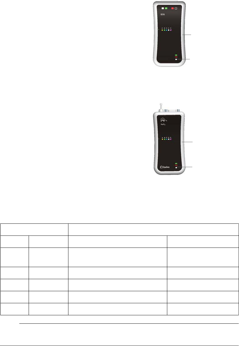
2‐8SystemOverviewExpressionMR200InstructionsforUse
wECG Module
ThewirelessECGmodule(wECG)transmitsmeasuredECG
signalsthroughawirelesslinktotheMR200.Themodule
alsoreceivesinformationtoperformcommandedtasks(for
example,leadconfigurationandfiltermodechanges).Two
ECGchannelscanbedisplayedandareavailablefor
interfacingwiththeMRsystemcardiacgatinginput.
wSPO2 Module
ThewirelessSPO2module(wSPO2)transmitsmeasured
bloodoxygensaturation,plethysmography,peripheralpulse
data(SPO2)andpneumaticrespirationvaluesthrougha
wirelesslinktotheMR200.Theprocessedinformationcan
bedisplayedandoutputforinterfacingtotheMRsystem
pulseperipheralandrespirationgatinginput.
Module Status Indicator
Eachmodulehasastatusindicator,atwo‐colorLED,thatdenotesthefollowingconditions.
NOTE
For battery details, see page 1-20; and, for communications details, see page 1-21.
wECG module
Status indicator
wSPO2 module
Status indicator
Indicator Module Status
Color State Power Communications
None Not
applicable
No battery is installed or the charge
is insufficient to power the module. Not applicable
Green Flashing Battery power good Not communicating
Green Solid Battery power good Good communication
Red Flashing Low battery condition Not communicating
Red Solid Low battery condition Good communication

ExpressionMR200InstructionsforUseSystemOverview2‐9
System Power-Up and Communications Verification
WARNING
Always perform operational verification prior to use and during monitoring by ensuring
proper communications between the MR200, the wireless modules and the IP5 (if equipped).
Failure to ensure proper communications can result in the loss of patient monitoring and the
loss of data transfer in networked systems equipped with an IP5. If a device fails to function
properly, remove it from use and contact technical support.
TheMR200reachesanoperationalstatewithin60secondspower‐upandattainsfull
measurementaccuracyafter2minutes.
ToapplypowertotheMR200andverifysystemcommunications
CAUTION
If power to wireless device with established communications is lost or removed, its network
connection will be dropped.
Step Action
1Ensurethatabatteryisinstalledineachwirelessmodule(seepage
1‐20).
2WiththecartbatteriesinstalledandwiththeMR200connectedto
ACpower(seepage1‐18),pressthepowerswitch.
3(Optional)ifequipped,turnontheIP5.
4Ensurethatthenetworksettingofeachmodule(seepage1‐21)
matchesthenetworksettingoftheMR200(seeonpage2‐16).
5EnsurethatthenetworksettingoftheIP5(ifturnedoninstep3,
above)matchesthenetworksettingoftheMR200.
6EnsuregoodcommunicationbetweeneachmoduleandtheMR200
bycheckingthemodule’sstatusiconontheLCD(seeonpage2‐
16).
7(Optional)ifequippedwithanIP5,proceedaccordingtotheprinter
option:
•Ifequippedwithaprinter,ensuregoodcommunication
betweentheMR200andtheIP5bycheckingtheprinting
statusiconontheLCD(seepage2‐16).
•Ifnotequippedwithaprinter,checkthedisplaypanelofthe
IP5forhostconnectiontotheMR200.
8Ensureproperoperationofeachpatientparameterandalarms.
Refertoappropriatechaptersinthismanual.
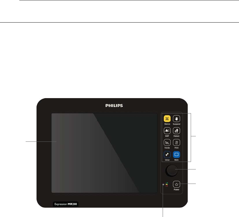
2‐10SystemOverviewExpressionMR200InstructionsforUse
System Parameters
TheMR200simultaneouslyprocessesanddisplaysmultipleparameters,waveforms,numeric
valuesandalarms.Allpatientinformationisprovidedonthedisplaypanel.Afullyequipped
MR200includesmonitoringforthefollowingparameters:
• Electrocardiogram(ECG),dualchannel
•Heartrate
•Bloodoxygensaturation/pulseoximetry(SPO2)
•Non‐invasivebloodpressure(NiBP)
•End‐tidalandinspiredCO2(CO2)
• Respiration(CO2orbellows)
NOTE
Depending upon the equipped options, your MR200 may not have all indicated parameters.
Display Panel
Thedisplaypanel,whichincludestheLCD,keypadandcontrolknob,formstheuserinterfaceof
theMR200.
LCD Keypad
Control knob
Status indicator
Power switch
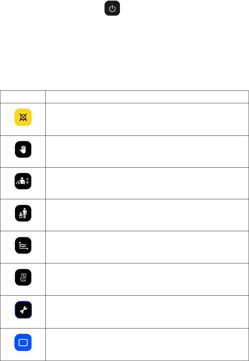
ExpressionMR200InstructionsforUseSystemOverview2‐11
Power Switch
Poweriscontrolledbythepowerswitch:
•PressthepowerswitchtoturnontheMR200.
•PressandholdthepowerswitchforapproximatelytwosecondstoturnofftheMR200.
Keypad
Thekeypadhaseightkeysforquickaccesstofrequentlyusedfunctions.
Key Function
Silence
Controls the alarm sound; see page 9-7 for details.
Suspend
Enters suspend mode; see page 2-19 for details.
NiBP
Begins a new NiBP measurement if no reading is in progress, or ends a
current measurement; see chapter 4.
Patient
Selects the type of patient to be monitored; see page 3-10 for details.
Trends
Accesses the HISTORY menu when in normal mode (see page 2-18) and
an individual graphic trend when a vital sign box is highlighted (see chapter
10).
Print
Initiates a 30 second print when using an equipped IP5.
Setup
Accesses the SETUP menu; see page 3-2 for details.
Main
Closes any menu and returns to the normal operating mode (see page 2-18)
2‐12SystemOverviewExpressionMR200InstructionsforUse
Control Knob
Thecontrolknoballowsyoutonavigateandselectoptions,itemsandsettingsinthemenu
system:
•Rotatingthecontrolknobclockwisemovesthe“cursor”downandrotatingtheknob
counterclockwisemovesthe“cursor”up.
•Inthenormalmode,rotatetheknobtohighlightdifferentvitalsignboxesandpressthe
knobtoopentheassociatedmenu.
•Whenamenuisdisplayed,rotatetheknobtohighlightoptionsanditemsandpressthe
knobtoselectthatoptionoritem.
•Whenaoptionisdisplayed,rotatetheknobtohighlightsettingsanditems,andpressthe
knobtoselectthatsettingoritem.
NOTE
In the menu system, grayed out panes, options labelled UNUSED or THIS ITEM IS LOCKED
when selected, reflect features or options that are inaccessible, not configured, or not installed.
Status Indicator
Thestatusindicatorisamulti‐colorLEDthatdenotesthepowerconditionofthecart,asdetailed
inthetablebelow.
Indicator Power Status
Color State Definition Power Switch
None Not
applicable
Not on external power (batteries may be
installed)
Off
Green Flashing AC power connected (batteries may be
installed)
Off
Green Solid On AC power (batteries, if installed, are
charging)
On
Yellow Solid On battery power On
Red Solid On battery power with a low battery condition
WARNING
A solid red light indicates battery
power has fallen below the required
limit and system shutdown with loss
of monitoring will occur. Immediately locate
an AC outlet and connect the MR200.
On
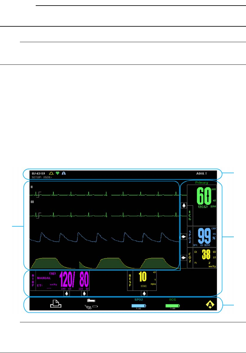
ExpressionMR200InstructionsforUseSystemOverview2‐13
LCD
Thedisplaypanelfeaturesacolorliquidcrystaldisplay(LCD).Alwaysadjustthecartsothatyour
viewoftheLCDcomplementsyourlineofsight.
CAUTION
Never apply unnecessary force to the LCD as it can result in screen damage or failure.
NOTE
To change the language displayed by the MR200, see page 11-16.
Display Areas
Fourdataareasaredisplayedinthenormaloperatingmode(seepage2‐18fordetails):
• Informationalarea(1,below)
•Vitalsignboxesarea(2,below)
• Communicationandpowerstatusdisplayarea(3,below)
•Vitalsigntracesarea(4,below)
NOTE
If a parameter (or an ECG trace) has been turned off, its portion of the LCD will be blank. To turn
a parameter on or off, use the PARAMETER SELECTION menu; see page 3- 7 for details.
1
2
3
4
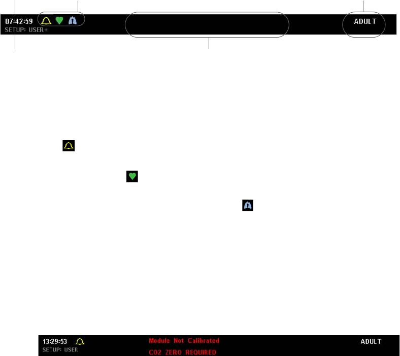
2‐14SystemOverviewExpressionMR200InstructionsforUse
Informational Area
Theinformationalarea,alongthetopofthescreen,providesuserandpatientinformation:
•Timeprovidescurrenttime,givenina12‐or24‐hourformat(hh:mm:ss);seeSetTimeon
page3‐12fordetails.
•Symbolareaprovidesindicationsofthealarmsoundsetting,configurationstatus,and
heartbeatandrespirationdetection.
–Theindicatesanactivealarmsoundsetting,displayedatalltimes(unless
temporarilyobscuredbyamenuordialogbox);seechapter9.
–Whenenabled,theindicatesheartbeatdetection,flashingforeachdetected
pulse;seeHRTONESOURCEonpage3‐9.
–WhenCO2isonandwithinspecifiedlimits,theindicatesrespirationdetection,
flashingatafrequencythatmatchesthecurrentbreathrate;seechapter7.
•Patientdisplaystheselectedpatienttype;seepage3‐10.
•Currentsetupnamedisplaysthepower‐ondefault(seepage3‐13)orthememoryblock
thatwasused(seepage3‐4)forthecurrentsetupofthemonitor,wheretheplussymbol
(+)indicatesasettingchangehastakenplace;seeSynchronizationonpage2‐2.
•Notificationareadisplaysuptotwoinformational,statusand/ortechnicalmessagesata
time;and,ifthreeormoreexist,themessageswillcycle.
(Twomessagesareshownintheexampleabove;seeListingofAlarmsonpage9‐16
formessagesanddetails.)
Vital Sign Boxes Area
Thevitalsign(VS)boxesarea,alongtherightsideandthelowerportionofthescreen,contains
individualpanesthatprovidevitalsignnumericdata,alarmlimitsettingsandviolationindictions,
trendarrowindications,andmenuaccessforeachoftheparameters.
Time Symbol area
Notification area
Patient
Current setup name
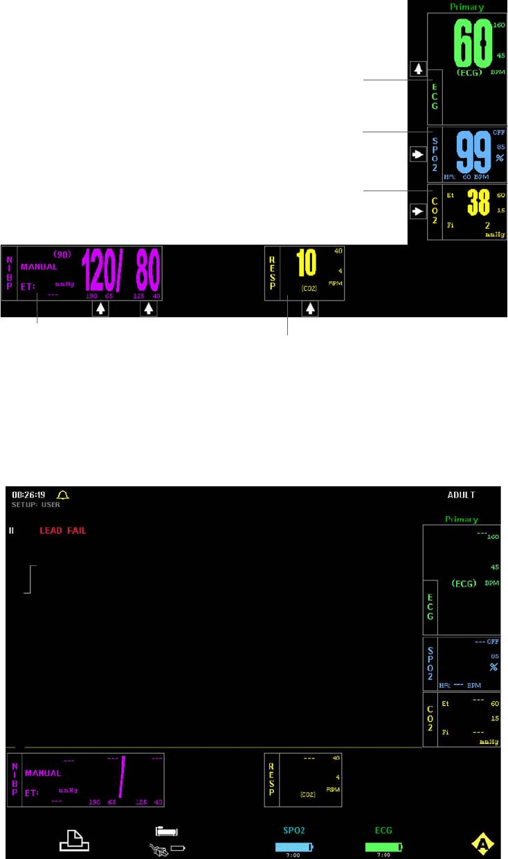
ExpressionMR200InstructionsforUseSystemOverview2‐15
No Data Available Indication
UndercertainconditionsoneormoreofthenumericsintheVSboxesmaydisplaythreedashes
(‐‐‐)toindicatethatnodataisavailable.
ECG VS box (see page 4-16)
SPO2 VS box (see page 5-7)
NiBP VS box (see page 6-7)
CO2 VS box (see page 7-6)
RESP VS box (see page 8-3)
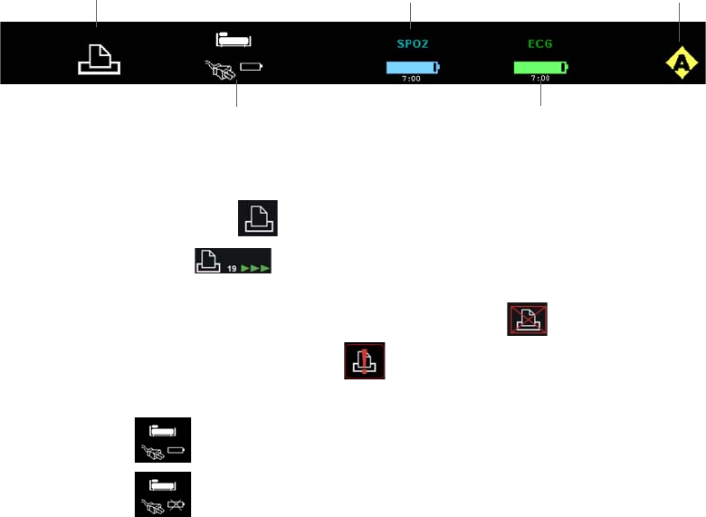
2‐16SystemOverviewExpressionMR200InstructionsforUse
Dependinguponthenatureofthisindication,analarmmaybegeneratedifnoparameterdatais
available.Inthiscase,thedasheswillbedisplayedinredandanalarmwillsound.
Analarmisgeneratedwhen:
• Parameterdatawaspresentbutisnolongeravailable(forexample,asensorthatwas
appliedmaynolongerbeconnectedtothepatient).
•Thehardwareassociatedwithaparameterhasexperiencedaproblemorfailurethat
preventsproperoperation.
Noalarmisgeneratedwhen:
•Amoduleoranothermeasurementdevicewasjustturnedonorappliedtothepatient
(allowafewsecondsforcommunicationtobeestablished).
•Thefirstreadinghasnotyetbeentakenortheparameterisinastart‐upcondition.
•Themeasurementvaluesaredistortedorthesignalisinadequate.
• Suspendmodewasjustexited.
Communication and Power Status Display Area
Thecommunicationandpowerstatusdisplayarea,alongthebottomofthescreen,provides
indicationsofthesystemnetworksetting,printingstatus,andthecommunicationandpower
statusofthecartandthewirelessmodules:
•PrintingstatusicondisplaysthestatusoftheIP5printer,whenequipped:
–Whenreadytoprint,isdisplayed.
–Whenprinting,isdisplayed,indicatingthetimeremaining(inseconds)
untilcompletion.
–Whennotinstalledorifacommunicationproblemexists,isdisplayed.
–Whenavailablebutunabletoprint,isdisplayed.
•Cartstatusiconindicatesthepowerstatusofthecart:
–WhereindicatesthecarthasbatteriesinstalledandisoperatingonAC
power.
–WhereindicatesthecarthasnobatteriesinstalledandisoperatingonAC
power.
Cart
status icon
Printing
status icon
wECG module
status icon
Network
icon
wSPO2 module
status icon
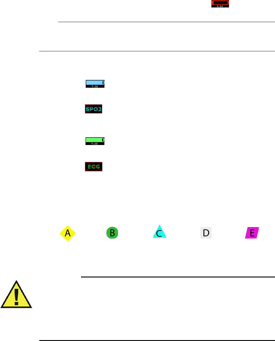
ExpressionMR200InstructionsforUseSystemOverview2‐17
–Whenonbatterypower,thebatterylevelwithatimeremainingcounterisdisplayed;
and,iflessthan45minutesofoperatingtimeremain,thenisdisplayedand
analarmissounded.
NOTE
After the start of battery power mode, the time remaining counter may take several minutes to
stabilize.
•wSPO2modulestatusiconindicatesthecommunicationandbatterystatusofthewSPO2
module:
–Whereindicatesthebatterylevel(withatimeremainingcounter,formatted
inhours:minutes).Iflessthan45minutesofoperatingtimeremain,thentheicon
turnsred,flashes,andanalarmissounded.
–Whereindicatesthereisnocommunicationbetweenthecartandmodule.
•wECGmodulestatusiconindicatesthecommunicationandbatterystatusofthewECG
module:
–Whereindicatesthebatterylevel(withatimeremainingcounter,formatted
inhours:minutes).Iflessthan45minutesofoperatingtimeremain,thentheicon
turnsred,flashes,andanalarmissounded.
–Whereindicatesthereisnocommunicationbetweenthecartandmodule.
•Networkiconindicates
thecurrentwirelessnetwork
channel
oftheMR200.Fivenetwork
channelsare
available(A–E),asshownbelow.Thischannelsettingcanbechangedtomeet
theneedsofyourfacilityandoperatingenvironment,butyoumustalsochangethesetting
ofthewirelessmodules(andIP5,ifequipped)tomatchthenew
MR200
channelforproper
systemcommunications
;seepage3‐15.
WARNINGS
• Care should be taken to guard against inadvertent changes to the network setting.
Before use, always ensure that all devices are communicating properly. Failure to do
so may cause a lapse in patient monitoring.
• In environments where multiple MR200s are being used, you must be aware of each
system’s network setting. Operating multiple MR200s on the same network or with a
wrong network setting will interfere with communications, and incorrect or corrupted
patient vital signs information will be displayed as a result.
Network
channel A
Network
channel B
Network
channel C
Network
channel D
Network
channel E
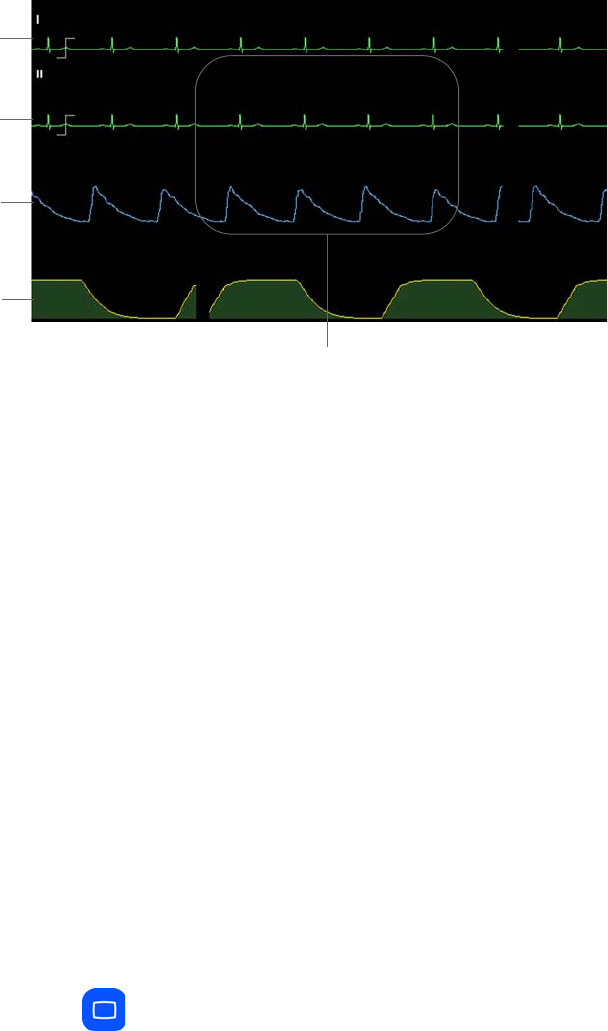
2‐18SystemOverviewExpressionMR200InstructionsforUse
Vital Sign Traces Area
Thevitalsigntracesarea,inthemiddleofthescreen,providesvitalsign(VS)waveformsand
systemstatusmessages.Tracewaveforms(A–D)areuniquelycoloredtomatchtheir
correspondingVSbox,andarefixedacrosstheLCDandupdatedwithanerasebar:
•TraceAisassignedanddisplayeddependingupontheECGmenuoptions;seepage4‐16.
•TraceBdisplaysECG2whentwoECGsourcesareon.
•TraceCdisplaystheSPO2waveform;seepage5‐7.
•TraceDdisplaystheCO2waveform;seepage7‐6.
•Systemmessageareaprovidessystemmessages,asdetailedthroughoutthismanualand
inListingofAlarmsonpage9‐16.
Modes of Operation
TheMR200hasthreedifferentoperatingmodes.
Normal Mode
Normalmodeisthestandardoperatingmode.Innormalmodetherearenoopenmenusor
highlightedvitalsignboxes;thesystemisreadyformonitoring.
Toenternormalmode
PresstheMainkey.
AnyopenmenuwillcloseandanyhighlightedVSboxwillbedeselected(thenormalscreenwillbe
displayed;seepage2‐13).
System message area
Trace A
Trace B
Trace C
Trace D

ExpressionMR200InstructionsforUseSystemOverview2‐19
Suspend Mode
Suspendmodesupportspatient‐clinicianinteractionwithoutnuisancealarms,whichisuseful
whereminimaluserinteractionisrequired(forexample,whileapatientisnotbeingmonitored,
duringtransitionswhenremovingthemonitorfromonepatientandconnectingitonanother,or
ifcertainadjustmentsarebeingmadetothedeviceorotherequipment).Insuspendmode,
currentpatientinformationisprovided,butwiththefollowingoperationalexceptions:
•Audiblealarmsaredisabled;
•ActiveautomaticNiBPmeasurementsaresuspended;
•DefaultinflationpressuresareusedforallmanualNiBPreadings;and,
•Automaticprintoutswillnotbegenerated.
Toentersuspendmode
PresstheSuspendkey.
SUSPENDEDwillbedisplayed(inred,nearthecenterofthescreen).
Toexitsuspendmode
PresstheSuspendkey.
Simulation Mode
Simulationmodesupportstrainingandtestingfunctionsbydisplayinginternally‐generateddata
forvitalsignwaveforms,numericsandstatuses.Insimulationmode,allpatientmonitoringis
discontinued.Forsimulationmodedetails,seepage11‐14.
2‐20SystemOverviewExpressionMR200InstructionsforUse

ExpressionMR200InstructionsforUseGettingStarted3‐1
CHAPTER 3
Getting Started
Initialsetupisimportanttoachieveexpectedresultsandseamlessoperation.Setupmenus
providetheabilitytoselectmonitoringoptions,controlfunctions,storeandrecalloperating
configurationsandaccesstestroutines.
CAUTIONS
• A minor but noticeable degradation in wireless module communications may occur in the
presence of high-powered radios.
• Prior to clinical use, the user must be aware of the minimum distance from the MR magnet
that must be maintained for proper operation; see Positioning the MR200 on page 2-6 for
details.
Monitor Initialization
Afterpower‐up,theMR200typicallytakesafewsecondstoinitialize.Duringthisperiod,theLCD
mayremainblankuntiltheprocesscompletes.TheMR200canbeginmonitoringfunctionsfrom
aninitialfactorydefaultstateorfromapre‐configuredstate,dependinguponthewaythestored
configurationsandpatientdataareprogrammedforstartup.
Visuallycheckingthepatientandconfirmingchangingmeasurementsagainstothervitalsigns
shouldbestandardroutinesduringuse.
Warning
WARNING
When using an IP5, make sure that the content of the RECALL SETUPS option matches
that of the MR200 option, and that the same option is selected as the default setup on both
systems (see page 3-4). This is important because the device first booted will determine the
power-on settings of the system (that is, the MR200 and IP5).
Initial Alarm Setting Indication
Afterpower‐upandimmediatelyfollowingtherecallofastoredsetup,theMR200providesan
initialindicationofthealarmvolumebysoundingthetoneatitscurrentsettingfor5seconds.
Duringthisinterval,CHECKALARMVOLwillbedisplayed.
AlarmHoldistheinitialstateofthealarmfunctionsfollowingpower‐up,andthenafterthewait
period(120seconds)Armedbecomesthenormalstate.IntheArmedstate,thealarmfunctions
3‐2GettingStartedExpressionMR200InstructionsforUse
operateasfollows:
•Thealarmtonewillsoundwhileanalarmconditionexists,providedthatanypre‐alarm
sounddelayhasexpiredandthesymbolisdisplayed.
•Messagesrelatedtootheralarmsoundstateswillberemovedfromthedisplay.
•Analarmconditionnotpreviouslyplacedinasilencedstatewillcausethealarmtosound
(providedthatanypre‐alarmsounddelayhasexpired).
SETUP Menu
FromtheSETUPmenu,youcanconfiguretheMR200tomeetyourpatientmonitoringneeds:
– Individualsetupconfigurationscanbesavedandrecalled.
– Availableparameterscanbeturnedonandoff.
–Patienttypecanbeselected.
– Soundscanbeadjusted.
–Dateandtimecanbeset.
– Networkdesignationcanbeset.
– Sweepandrespirationspeedscanbeselected.
–Defaultconfigurationforstart‐upcanbeselected.
–Alarmlimitscanbeset.
– Remoteprinterfunctionscanbeselected.
Warning
WARNING
When using an IP5, wait at least 4 seconds if performing a recall or setting a parameter
value, as these require a few seconds to propagate through the system. Performing another
recall within 4 seconds of a previous recall or after a value change, may result in improperly
recalled data.
TheSETUPmenuaccessesmenusforsetupandcontroloftheMR200.
ToentertheSETUPmenu
PresstheSetupkey.
ThefollowingoptionsareavailableintheSETUPmenu:
•ALARMSETUP(seechapter9fordetails)
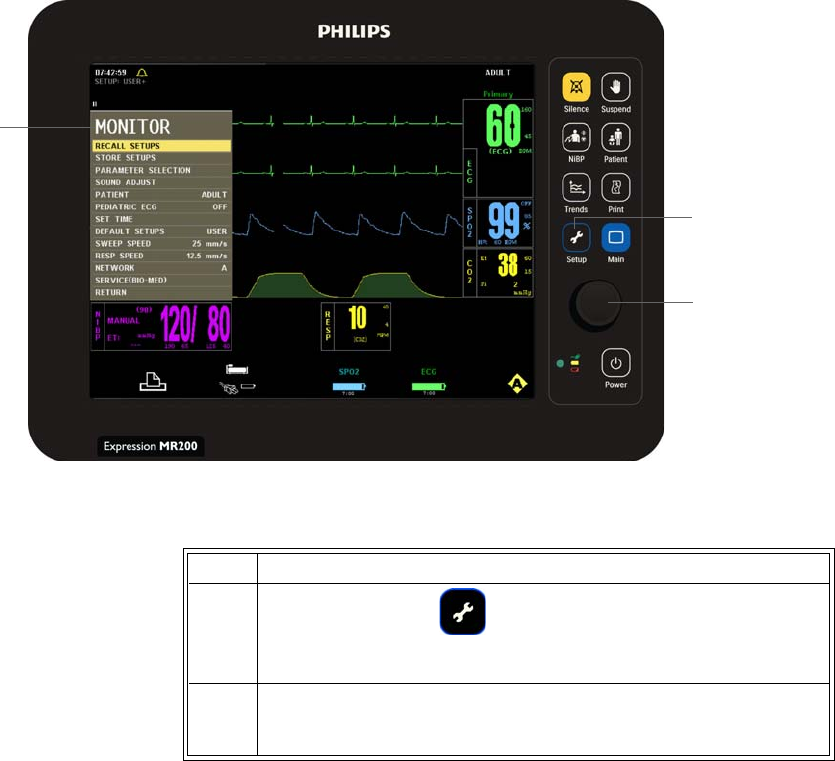
ExpressionMR200InstructionsforUseGettingStarted3‐3
MONITOR Menu
TheMONITORSETUPoption(intheSETUPmenu)openstheMONITORmenu,whichcontains
optionsforsetupandcontrolofpatientmonitoring.
.
TochangesettingsintheMONITORmenu
• MONITORSETUP(seebelow)
•PRINTERSETUP(seechapter10fordetails)
Setup key
Control knob
MONITOR
menu
Step Action
1PresstheSETUPkey.
TheSETUPmenuappears.
2TurnthecontrolknobtoMONITORSETUPandthenpresstheknob.
TheMONITORmenuappears.Currentsettingsaredisplayed.

3‐4GettingStartedExpressionMR200InstructionsforUse
RECALL SETUPS
Restoresthemonitortoaparticularsetupthatwaspreviouslysaved(seeSTORESETUPSonpage
3‐5forconfigurationdetails,andseeDEFAULTSETUPSonpage3‐13forthepower‐onsetting.)
NOTE
The name of the current setup is displayed in the top left corner of the screen (see page 2-14). If a
setup was changed, a plus symbol (+) will appear next to the setup name ( A–F, User or Factory).
Thefollowingmemoryblockchoicesareavailable:
•A
•B
•C
•D
3Turnthecontrolknobtoselectanyofthefollowingsystem‐wide
optionsandthenpresstheknob:
RECALLSETUPS
STORESETUPS
PARAMETERSELECTION
SOUNDADJUST
PATIENT
PEDIATRICECG
SETTIME
DEFAULTSETUPS
SWEEPSPEED
RESPSPEED
NETWORK
SERVICE(BIO‐MED)
Foroptionsinformation,seetheappropriatesectionsbelow.
4Turntheknobtothedesiredsettingandthenpresstheknob.
5Tochangeothersettings,repeatsteps3and4.
6PresstheMainkeytoclosethemenu.
Alternative:TurntheknobtoRETURNandthenpresstheknob,or
waitapproximately60seconds.
Step Action
ExpressionMR200InstructionsforUseGettingStarted3‐5
•E
•F
•USER(Factoryprogrammingwillberecalledifthisoptionisselectedbutwasnotpreviously
stored;seepage3‐5.)
Torecallasetupfrommemory
STORE SETUPS
Storesuptosevensetupsfordifferentprocedures,patienttypesorusers,whichcanthenbe
recalledwithouttheneedofextrasetup.Thesememoryblocksaremaintainedbyalonglife
batteryorstaticRAM,savingthedata,evenwhenpoweredoff.Storablesettingsinclude:
– Systemsetups
–Patienttype,alarmssettings,auto‐setcalculationpercentage,latchedorunlatchedand
soundlevel
–ECGselectedlead,scale,tracespeed,filtermode,magnetcontrol,QRStonecontroland
heartratesource
–SPO2size,averagingtimeandHRtonesource
–CO2size,grids,unitsandrespirationspeed
Step Action
1PresstheSETUPkey.
TheSETUPmenuappears.
2TurnthecontrolknobtoMONITORSETUPandthenpresstheknob.
TheMONITORmenuappears.Currentsettingsaredisplayed.
3TurnthecontrolknobtoRECALLSETUPSandthenpresstheknob:
TheRECALLSETUPSmenuappears.
4Turnthecontrolknobtoselectoneofthefollowingmemoryblocks
andthenpresstheknob:
A
B
C
D
E
F
USER
Theselectedmemoryblockisrecalledforthesettingsofthe
MR200.(Ifdisplayed,the“+”symbolisremoved.)

3‐6GettingStartedExpressionMR200InstructionsforUse
–NiBPmanualorautosettingandautomatictimeinterval
–Trendgraphtimebaseandscale
–Printcontrol,tracedelay,speedandselectedtraces
Thefollowingmemoryblockchoicesareavailable:
•A
•B
•C
•D
•E
•F
•USER
Tostoreasetupinmemory
Step Action
1ConfigurethesettingsandoptionsoftheMR200asdesired.
2PresstheSETUPkey.
TheSETUPmenuappears.
3TurnthecontrolknobtoMONITORSETUPandthenpresstheknob.
TheMONITORmenuappears.Currentsettingsaredisplayed.
4TurnthecontrolknobtoSTORESETUPSandthenpresstheknob:
TheSTORESETUPSmenuappears.
5Turnthecontrolknobtoselectoneofthefollowingmemoryblocks
andthenpresstheknob:
A
B
C
D
E
F
USER
Theconfigurationisstoredintheselectedmemoryblock.(If
displayed,the“+”symbolisremoved.)

ExpressionMR200InstructionsforUseGettingStarted3‐7
PARAMETER SELECTION
Controlsmonitoringfunctions,asindicatedbytheabsenceorpresenceoftheVSboxforthe
parameter,exceptECG(seebelow).
Thefollowingchoicesareavailable:
•ECGallowselectrocardiogrammonitoring:
–ONturnsontheECGparameter.(Default)
–OFFturnsofftheECGparameter.HeartratewillremainintheVSboxallowingitto
bedisplayedfromanotherselectedsourceorifHRSOURCEissettoAUTOandECGis
inaLEADFAILcondition.
•NiBPallowsnon‐invasivebloodpressuremonitoring:
–ONturnsontheNiBPparameter.(Default)
–OFFturnsofftheNiBPparameter.
•SPO2allowsoxygensaturationofarterialbloodmonitoring:
–ONturnsontheSPO2parameter.(Default)
–OFFturnsofftheSPO2parameter.
•CO2allowsCO2andrespirationmonitoring(ifinstalled):
–ONturnsontheCO2andtheCO2‐derivedrespirationparameter.
–OFFturnsofftheCO2parameter.(Default)
•RESPallowsbellowsrespirationmonitoring:
–ONturnsonthebellows‐derivedrespirationparameter.
–OFFturnsofftherespirationparameter.(Default)
Tocontrolaparameter
Step Action
1PresstheSETUPkey.
TheSETUPmenuappears.
2TurnthecontrolknobtoMONITORSETUPandthenpresstheknob.
TheMONITORmenuappears.Currentsettingsaredisplayed.
3TurnthecontrolknobtoPARAMETERandpresstheknob.
ThePARAMETERmenuappears.
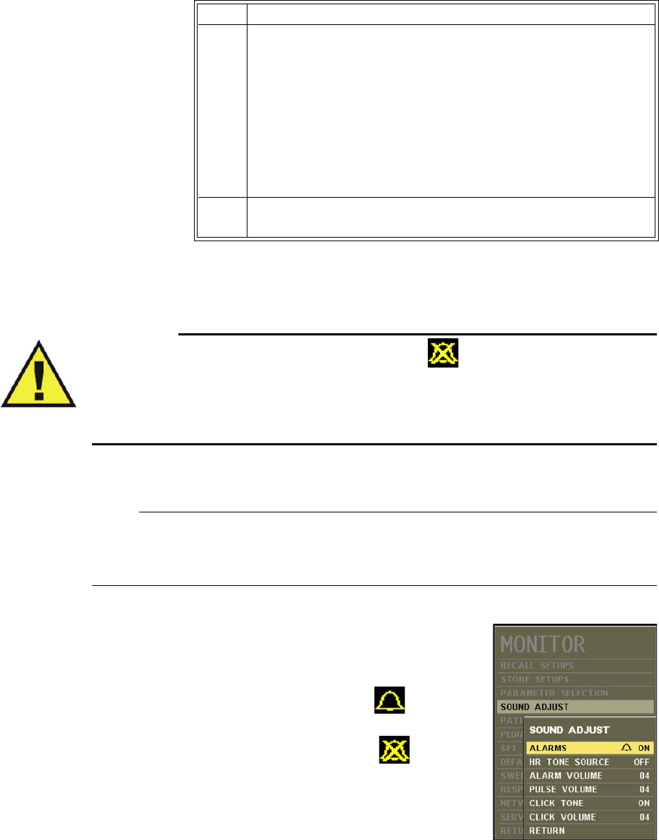
3‐8GettingStartedExpressionMR200InstructionsforUse
SOUND ADJUST
Warning
WARNING
The alarm sound can be turned off, as indicated by the symbol. Always ensure that the
alarm sound setting is appropriate for the monitoring environment and for each patient. The
alarm sound volume is adjustable for suitability to various clinical environments. When you
use the MR200, always ensure that the alarm sound can be heard above the ambient noise
level; otherwise, treatment of the patient could be delayed.
Controlsalarm,heartrateandkeypadtones,andthevolumesettingsforeach.
NOTE
While in this menu, tones generated during patient monitoring are disabled and REAL TONES
DISABLED will be displayed.
Thefollowingchoicesareavailable:
•ALARMScontrolsthealarmsound(identicaltoand
interactivewithALARMSOUND;seepage9‐12):
–ONturnsonthealarmsound,whereindicates
thatthesoundhasbeenenabled.(Default)
–OFFturnsoffthealarmsound,whereindicates
thatthesoundhasbeendisabled.(Onlythealarm
soundwillbedisabled;thevisualalertfromthesource
oftheviolationstillflashesinred.)
4Turnthecontrolknobtoselectoneofthefollowingparametersand
thenpresstheknob:
ECG
NiBP
SPO2
CO2(ifinstalled)
RESP
Theparameter’sactivationmenuappears.
5Turntheknobtothedesiredsettingandthenpresstheknob.
Step Action

ExpressionMR200InstructionsforUseGettingStarted3‐9
•HRTONESOURCEsetsthesourceusedfortheheartratetone(identicaltoandinteractive
withthesameoptionintheECGandSPO2menus):
–OFFremovestheheartsymbolfromthedisplayandproducesnotone.(Default)
–QRSprovidesatonemodulatedbytheQRSdetectionfromtheECGvitalsign.
–SPO2providesatonemodulatedbytheSPO2vitalsign,wherealowervalue
producesalowerpitch.
•ALARMVOLUMEsetsthealarmsoundlevelfrom1–10.(Default=4)
•PULSEVOLUMEsetsthepulsetonevolumefrom1–10.(Default=4)
•CLICKTONEcontrolsthekeypadtonegeneration.(Default=On)
•CLICKVOLUMEsetstheclicktonevolumefrom1–10.(Default=4)
Toadjustthesounds
Step Action
1PresstheSETUPkey.
TheSETUPmenuappears.
2TurnthecontrolknobtoMONITORSETUPandthenpresstheknob.
TheMONITORmenuappears.Currentsettingsaredisplayed.
3TurnthecontrolknobtoSOUNDADJUSTandpresstheknob.
TheSOUNDADJUSTmenuappears.
4Turnthecontrolknobtoselectoneofthefollowingmenusand
thenpresstheknob:
ALARMS
HRTONESOURCE
ALARMVOLUME
PULSEVOLUME
CLICKTONE
CLICKVOLUME
Theselectedmenuappears.
5Turntheknobtothedesiredsettingandthenpresstheknob.
Thesettingisenteredandabriefsoundatthecorrespondinglevel
isproduced.

3‐10GettingStartedExpressionMR200InstructionsforUse
PATIENT
Selectsthetypeofpatienttobemonitored.
DeterminingthePatientType
IEC80601‐2‐30Edition1.0,theinternationalstandardregardingparticularrequirementsfor
safety,includingessentialperformanceofautomaticcyclingnon‐invasivebloodpressure
monitoringequipment,definespatienttypesintwocategories:neonatalandadult.Neonatal
patientsaredefinedbytheapproximateagerangeofbirthtoafewweeks.Allotherpatientsare
identifiedasadults.
ANSI/AAMISP10:2008,theAmericanNationalStandardformanual,electronic,orautomated
sphygmomanometers,definespatienttypesaccordingtoagelimitations,asindicatedinthetable
below.
Similarly,theFood&DrugAdministrationdefinespatientswithintwocategories:pediatricsand
adults.Eachcategoryisfurtherdefinedintosubgroupsaccordingtoapproximateage.
CAUTION
There may be occasions when a particular mode is not suitable for its apparent category of patients
based on age alone. In these cases, a clinical decision shall be made to use another patient type or
measurement technique. The clinical decision shall be based on all of the factors listed in
Determining Patient Type (above) to ensure the best possible and most timely measurement
acquisitions.
Regardlessofthedefinition,eachagencyrecognizesthatthepatienttypedescriptionscanbe
arbitraryandthatthefollowingpatientfactorsaremoreaccurateindeterminingtheappropriate
methodofpatientmonitoringandtreatment:
–Weight
–Bodysize
Patient Type Age
Neonatal Birth to 28 days
Pediatric 29 days to 12 years
Adult Greater than 12 years
Patient Type Subgroup Approximate Age Range
Pediatric Newborn (neonate) Birth to 1 month
Pediatric Infant Greater than 1 month to 2 years
Pediatric Child Greater than 2 to 12 years
Pediatric Adolescent Greater than 12 to 21 years
Adult --- Greater than 21 years

ExpressionMR200InstructionsforUseGettingStarted3‐11
–Limbcircumference
– Physiologicaldevelopment
–Neurologicaldevelopment
– Neuromuscularcoordination
Accordingly,theMR200usesseveraloperationalparameters,includingcuffinflationpressure
andpulsesensitivity,thatvarydependingontheselectedpatienttype.(Alwaysreferto
informationaboutthecorrespondingparameterforotherpossibleconsiderationswhen
determiningthepatienttype.)
Thefollowingpatienttypesareavailable:
•ADULT(Default)
•PEDIATRIC
•NEO(whenselected,PEDIATRICECGisalwayson.)
NOTE
Changing the PATIENT type causes the alarm to sound, the PATIENT indication to be revised,
CHANGE NiBP CUFF to be displayed for 30 seconds, and the alarm limit settings to revert to
the default values (see the table on page 9-15 for details).
Toselectthepatienttype
PressthePatientkey.Turnthecontrolknobtothedesiredtypeandthenpresstheknob.
PEDIATRIC ECG
ProvidesadditionalECGfilteringwhenpatients,particularlypediatrics,presentwithnarrowQRS
complexesand/orhigh(120BPM)heartrates.
Thefollowingchoicesareavailable:
•OFFturnsthepediatricECGfilteroff.(Default)
•ONprocessesECGdatausingapediatricalgorithm,inadditiontothegradientfilter
setting,andoperatesunderthefollowingconditions:
–WhenanECGtraceisprinted,PEDECG=ONorPEDECG=OFFwillappearonthestrip.
–ThesettingwillbesavedduringSTORESETUPSandrecalledduringRECALLSETUPS.

3‐12GettingStartedExpressionMR200InstructionsforUse
NOTE
When PATIENT is set to NEO, PEDIATRIC ECG is set to ON and locked. When the PATIENT
type is changed to ADULT, PEDIATRIC ECG will be set to OFF and unlocked.
TocontrolthepediatricECGfilter
SET TIME
Setsthetimeanddate.Thetime,continuouslyoperating,isdisplayedonLCDandthedate
formatisMMMDD,YYYY(forexample,JAN01,2013).
Thefollowingchoicesareavailable:
•FORMATchangestheformatofthedisplayedtime
–12hour
–24hour(Default)
•SECONDsetsthesecond.
•MINUTEsetstheminute.
•HOURsetsthehour.
•DAYsetstheday.
Pediatric ECG Patient Type Condition
Off Adult Unlocked
On Pediatric Unlocked
On Neonatal Locked
Step Action
1PresstheSETUPkey.
TheSETUPmenuappears.
2TurnthecontrolknobtoMONITORSETUPandthenpresstheknob.
TheMONITORmenuappears.Currentsettingsaredisplayed.
3TurnthecontrolknobtoPEDIATRICECGandpresstheknob.
ThePEDIATRICECGmenuappears.
4Turnthecontrolknobtothedesiredsettingandthenpressthe
knob.

ExpressionMR200InstructionsforUseGettingStarted3‐13
•MONTHsetsthemonth.
•YEARsetstheyear.
•ENTERsavesanychanges.
Tosetthetimeanddate
DEFAULT SETUPS
SelectstheinitialsettingsusedwhenpowerisappliedtotheMR200.
Thefollowingchoicesareavailable:
•FACTORYusesthefactoryprogrammedsettings.(Default)
•USERusessettingsfromtheUSERmemoryblock;seeRECALLSETUPSonpage3‐4.
Step Action
1PresstheSETUPkey.
TheSETUPmenuappears.
2TurnthecontrolknobtoMONITORSETUPandthenpresstheknob.
TheMONITORmenuappears.Currentsettingsaredisplayed.
3TurnthecontrolknobtoSETTIMEandpresstheknob.
TheSETTIMEmenuappears.
4Turnthecontrolknobtoselectanyofthefollowingtimeoptions
andthenpresstheknob:
FORMAT
SECOND
MINUTE
HOUR
DAY
YEAR
Theselectedoptionappears.
5Turntheknobtothedesiredsettingandthenpresstheknob.
6Tochangeothersettings,repeatsteps4and5.
7TurnthecontrolknobtoENTERandthenpresstheknob.
Thechangesaresaved.
3‐14GettingStartedExpressionMR200InstructionsforUse
Tosetthedefaultsetups
SWEEP SPEED
ChangesthetracespeedofallwaveformsexceptCO2.
Thefollowingsweepspeedchoices(inmillimeterspersecond)areavailable:
•50mm/s
•25mm/s(Default)
Toadjustthesweeprate
SeeChangingtheWaveformSpeedonpage4‐17.
RESP SPEED
SetsthetracespeedoftheCO2waveform.
Thefollowingsweepspeedchoices(inmillimeterspersecond)areavailable:
•25mm/s
•12.5mm/s(Default)
•6.25mm/s
•3.125mm/s
•1.5625mm/s
Step Action
1PresstheSETUPkey.
TheSETUPmenuappears.
2TurnthecontrolknobtoMONITORSETUPandthenpresstheknob.
TheMONITORmenuappears.Currentsettingsaredisplayed.
3TurnthecontrolknobtoDEFAULTSETUPSandpresstheknob.
TheDEFAULTSETUPSmenuappears.
4Turnthecontrolknobtoselectoneofthefollowingoptionsand
thenpresstheknob:
FACTORY
USER
Thepower‐ondefaultisset.

ExpressionMR200InstructionsforUseGettingStarted3‐15
• 0.33333mm/s
ToadjustthesweeprateforCO2respiration
SeeChangingtheWaveformSpeedonpage7‐6.
NETWORK
Setsthewirelesscommunicationschannelforthecart.Thenetworkusedbythecartandthe
wirelessmodulesmustbethesame.
Thefollowingnetworkchoicesareavailable:
•A(Default)
•B
•C
•D
•E
Tosetthenetwork
Step Action
1PresstheSETUPkey.
TheSETUPmenuappears.
2TurnthecontrolknobtoMONITORSETUPandthenpresstheknob.
TheMONITORmenuappears.Currentsettingsaredisplayed.
3TurnthecontrolknobtoNETWORKandpresstheknob.
TheNETWORKmenuappears.
4Turnthecontrolknobtoselectoneofthefollowingoptionsand
thenpresstheknob:
A
B
C
D
E
TheMR200networkchannelisset.
5IfequippedwithanIP5,ensurethatthenetworkusedbythe
wirelessmodules(seepage1‐21)andtheIP5areidenticaltothe
selectionmadeinstep4.
3‐16GettingStartedExpressionMR200InstructionsforUse
SERVICE(BIO-MED)
Allowsaccesstopressureandmiscellaneousconfigurationsettings,diagnosticroutinesand
firmwareinformation;seepage11‐12fordetails.

ExpressionMR200InstructionsforUseMonitoringECG4‐1
CHAPTER 4
Monitoring ECG
Electrocardiogram(ECG)monitoringinsidetheMRIenvironmentisuniqueandrequires
additionalprecautionstopermitsafepatientprocedures.Itisalwaysimportanttoremember
thattheriskofradiofrequency(RF)heatingiseverpresentwhenanyelectricalconductors(for
example,ECGleadcables)areplacedintheMRsystembore.Byfollowingtheoperating
precautions,warningsandtheguidelinesbelow,theseriskscanbeminimized.TheECG
parameterisintendedforECGmonitoringmodeandnotdiagnosticECGmonitoring.
WARNINGS
•The MR200 is not intended for use with patients using pacemakers or electrical
stimulators.
• Arrhythmias, erratic heartbeats, operation of electrical stimulators, pacemakers and
patient motion can result in inaccurate readings. Rate meters may continue to count
pacemaker rates during occurrences of cardiac arrest or some arrhythmias. Do not
rely entirely upon rate meter alarms. If questionable readings are obtained, check the
patient's vital signs by alternate means before administering medication.
CAUTION
Pacer pulses are not specifically rejected by the MR200 and may be treated as part of MRI
gradient noise. Gradient filtering attempts to remove high frequency pulse shaped waveforms from
the ECG signal which may resemble pacer waveforms, and it is possible that the pacer waveform
may be removed with the gradient noise.
wECG Module and Lead Cable
ThewECGmoduleandleadcableareintendedforpatientuseswhencontinuousECGmonitoring
orcardiacgatingarerequired.ThewECGmoduleandleadcablemaybeusedintheMRsystem
bore,althoughthemodulemustnotbeplacedwithintheMRIfieldofview(FOV).
CAUTIONS
• If dropped, the wECG module must be verified for correct operation before use.
• Guard against the accidental ingress of liquid into the module, as measurements made by the
device can be adversely affected.
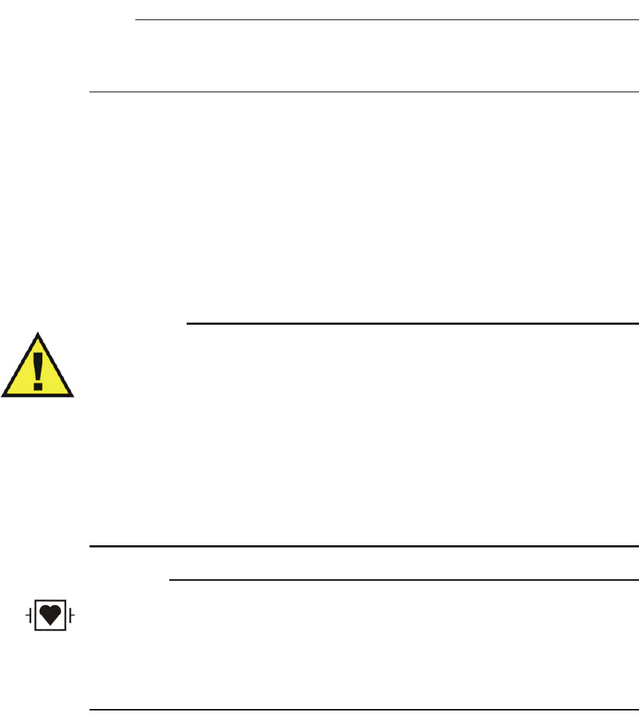
4‐2MonitoringECGExpressionMR200InstructionsforUse
NOTE
Refer to your facility's biohazard procedure for disposal of ECG lead cables when they become
unusable. Usually cables are disposed of as medical waste per facility procedures.
Defibrillator Use
TheMR200hasadefibrillation‐proofdegreeofprotectionthatallowsapatienttobe
defibrillatedwhileconnectedtothewECGmoduleandleads.Whenusingadefibrillator,follow
allprecautionsrelatedtoboththeMR200andthedefibrillatorequipment.Duringadefibrillation
procedure,theECGwaveformwillsaturatethenrecoverinlessthan5secondsinaccordance
withAAMI/ANSIEC13andIEC60601‐2‐27.
WARNINGS
•The patient connector inputs for all parameters are protected against the use of a
defibrillator by internal circuitry when the recommended patient cables or accessories
are used.
• Defibrillation and electrosurgery: Do not touch the patient, or table, or instruments,
during defibrillation.
• The MR200 can be used in the presence of defibrillators or electrosurgery units,
provided the equipment being used is in good working order, meeting appropriate
safety standards, is properly grounded and is operated correctly in the appropriate
manner and environment. Improperly grounded equipment can be a safety hazard
and can also cause interference to the ECG signal and result in a noisy ECG signal
waveform and inaccurate heart rate measurements.
CAUTION
When using a defibrillator, do not introduce discharges of 360 joules or more, repeated five times
over 5 minutes. Read the safety instructions provided with the defibrillator. The MR200 Cart is
designed to withstand defibrillation and will recover within 5 seconds (per IEC 60601-1,
Requirements for the Safety of Medical Electrical Equipment), and IEC 60601-2-49, Particular
requirements for the basic safety and essential performance of multifunction patient monitoring
equipment).
ExpressionMR200InstructionsforUseMonitoringECG4‐3
Patient Preparation for ECG Monitoring
WhenmonitoringECG,thesiteselectedonthepatient,theQuadtrodeelectrodeandECGlead
cable,thefilterandleadviewsettingofthemonitor,andtheambientenvironmentwillimpact
theperformanceandoperationoftheparameter.
ECG Site Considerations
MonitoringECGintheMRenvironmentisparticularlychallengingbecauseoftheinherent
distortionoftheECGwaveformcausedbytheMRmagneticfield.Thesebloodflowinduced
distortionsoftheECGareduetothelargeamountofbloodmovingthroughthevesselsofthe
heart(aorta).Blood(a verygoodelectricalconductor)movingthroughthelargemagneticfieldof
theMRproducesanelectricalpotentialthataddstotheECGsignal.Thisinducedelectrical
potentialisseenprimarilyasanaugmentationoftheECGT‐waveamplitude,althoughothernon‐
specificwaveformchangesarealsoapparentontheECG.SinceanelevatedT‐waveorST
segmentwillbeassociatedwithtruephysiologicdisorders,thestaticmagneticfield‐induced
ECG‐distortionswillbeproblematic.Forthisreason,abaselinerecordingoftheECGpriorto
placingthepatientinsidetheMRmagnetroomwillbenecessary.Theproperplacementofthe
ECGelectrodesintheMRIiscriticaltoreducingthebloodflowinduceddistortionoftheECG
waveform.WithproperstrategicplacementoftheECGelectrodesandminimizationofthelead
cablelength,thisbloodflowinduceddistortioncanbekepttoaminimum.Followingthe
instructionsprovidedonthespecificQuadtrodefoilpackagingwillminimizethebloodflow
induceddistortionontheECGsignal.Additionalartifactscausedbythestatic,gradientandRF
electromagneticfieldscanseverelydistorttheECG,makingobservationofthemorphologic
changesanddetectionofarrhythmiaquitedifficult.MonitoringadifferentECGlead(I,II,III,AVL,
AVR,AVF)willminimizesomeoftheseartifacts.
ECG Quadtrode Electrode Types
OnlyusespecifiedQuadtrodeelectrodeswiththeMR200asthiswillminimizethepossibleriskof
ECGelectrodeandcableheatingduringMRIprocedures,andreducetheamountofMRI‐
generatedartifactsontheECGwaveform.ThreeQuadtrodeelectrodetypesareavailabletomeet
thedifferentpatientandECGperformanceneeds:
•QuadtrodeMRIECGPAD(REF989803179031)forgeneralMRIproceduresforadultsand
pediatricpatientsweighingmorethan10kg(22pounds).
•ELCTRD,MRIECG,CV(REF989803179041)forcardiovascular(CV)MRIprocedures.
•ELCTRD,MRI,NEO(REF989803179051)forgeneralMRIproceduresforinfantsand
neonatalpatientsweighinglessthan10kg(22pounds).

4‐4MonitoringECGExpressionMR200InstructionsforUse
Selecting the Quadtrode Electrode and ECG Lead Cable
ECGleadcablesarespeciallyconstructedtoavoidpatientheatingbyreducingtheamountof
radiofrequency(RF)energythatcanflowthroughthewires.Suggestedapplicationsandthe
recommendedleadcable(forpartnumbers,seepage1‐26)andelectrodepairingsareprovided
below.
Selecting the Quadtrode Electrode Placement Site
Foroptimalperformance,usetheillustrationsbelowasplacementguidelineswhenapplyingthe
Quadtrodeelectrodetothepatient.
NOTE
In the illustrations below, an imaginary nipple line is denoted by the horizontal axis.
Cable,4LD,MRIECGwithQuadtrodeelectrode(REF989803179031):
–Forallpatientsweighingover22pounds(10kg)
–Usewithallscansexceptcardiovascularscans
Cable,4LD,CVMRIECGwithQuadtrodeelectrode(REF989803179041):
–ProvidesthebestECGperformanceforallprocedures
–Worksbestonfemalesandoverweightpatients
Cable,4LD,NEO.MRIECGwithQuadtrodeelectrode(REF989803179051):
–Designedforinfantsandneonatesweighingunder22pounds(10kg)
–Forsedationandgeneralanesthesiaapplications
Cable,AdvancedFilterECGwithQuadtrodeelectrode(REF989803179041):
–DesignedtominimizethegradientartifactontheECGtrace
Cable,AdvancedAppsECGwithQuadtrodeelectrode(REF989803179041):
–Designedtoallowforwideelectrodeplacement
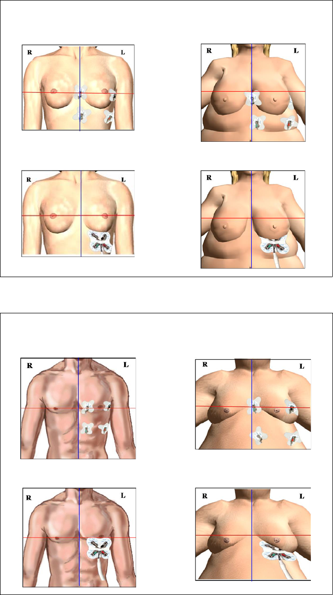
ExpressionMR200InstructionsforUseMonitoringECG4‐5
Selectingsitesonadultfemalepatients
Selectingsitesonadultmalepatients
Averageweightadultfemale Overweightadultfemale
CVQuadtrode(preferred)CVQuadtrode(preferred)
StandardQuadtrodeStandardQuadtrode
Averageweightadultmale Overweightadultmale
CVQuadtrode(preferred)CVQuadtrode(preferred)
StandardQuadtrodeStandardQuadtrode
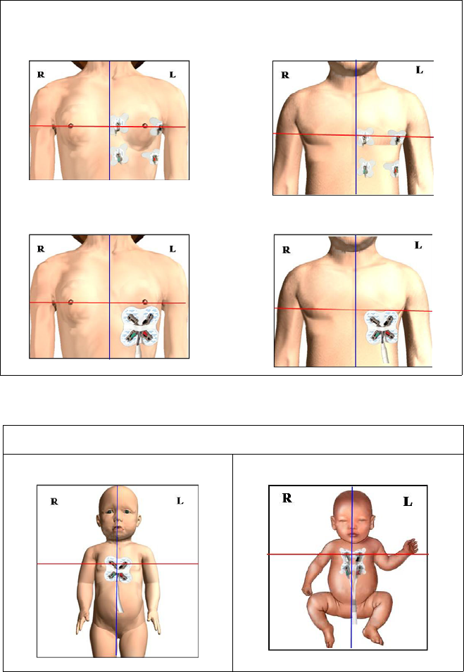
4‐6MonitoringECGExpressionMR200InstructionsforUse
Selectingsitesonpediatricpatients
Selectingsitesoninfantsandneonatalpatients
*Forpatientsweighinglessthan22pounds(10kg)
Pediatricfemale Pediatricmale
CVQuadtrode(preferred)CVQuadtrode(preferred)
StandardQuadtrodeStandardQuadtrode
InfantsandNeonates
StandardQuadtrode NeonatalQuadtrode*

ExpressionMR200InstructionsforUseMonitoringECG4‐7
Preparing the ECG Site
Toprepareanelectrodesiteonapatient
NOTES
• The ECG Skin Prep gel contains light abrasive pumice and saline that clean and enhance
the conductive properties of the skin, thus enhancing ECG performance. This practice also
helps remove ambient artifacts, such as the 50/60 hertz noise generated by the MR
environment.
• Isopropyl/rubbing alcohol must not be used to prep the site as it breaks down the conductive
properties of the skin, thus degrading ECG performance.
Checking Electrode Contact Quality
ProperQuadtrodeelectrodepreparationiscriticaltoECGperformance.Theresultofpoor
electrodepreparationwillbepoorECGmonitoringperformance.Ifelectrodecontactispoor,
thenremoveanddiscardtheelectrode,andrepeatthesitepreparationprocessaccordingtothe
instructionsabove.Neverreuseanelectrodeasitsadhesivewillnotsecurelyfastentotheskin.
Step Action
1ChecktheexpirationdateoftheQuadtrodeelectrodepackage.
2Ifnecessary,shavetheapplicationareatoremovehairfromthe
selectedelectrodesite(s).
3ApplyECGSkinPrepGel(REF989803152291)toagauzepad.
4Brisklyrubtheselectedsite(s)withthegauzepad(theskinmay
turnpink).
5 Removeanyexcessgelwithacleangauzepad.
6 FollowtheplacementinstructionsprovidedoneachQuadtrode
package.(Alsoreferencetheillustrationsabove.)
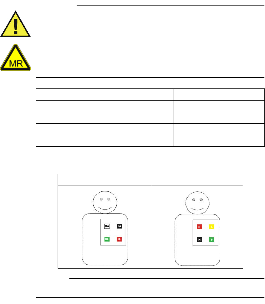
4‐8MonitoringECGExpressionMR200InstructionsforUse
Attaching the Lead Cable
Designatorsontheleadcablereferenceplacesonthetorsowheretheelectrodesshouldreside
inrelationtothepatient’sextremities.However,dependinguponthecabletype(IECorAHA),
therespectivecablesusedifferentdesignatorsandcolorstoreferenceleadplacement.
WARNINGS
• Never use any ECG lead cables other than the specified ECG lead cables.
• High levels of RF energy may cause patient heating or burns.
• Lead cables that become inadvertently looped during an MRI examination may act as
conductive lines for RF induced currents, resulting in excessive heating and possible
burns. When lead cables or other cables form a conductive loop in contact with the
patient's tissue, minor to severe burning can result. Please refer to the additional
information in Appendix D to prevent excessive heating associated with MRI
procedures. Follow steps to minimize the risks of MRI-related heating on page 4-12.
TheconnectiondiagramsbelowillustrateplacementofeachtypeofECGleadcable.
CAUTION
ECG clip leads should not be placed on the patient’s extremities.
Limb AHA Lead Designator, Color IEC Lead Designator, Color
Right arm RA, White R, Red
Right leg RL, Green N, Black
Left arm LA, Black L, Yellow
Left leg LL, Red F, Green
AHA Lead Cable Connections IEC Lead Cable Connections
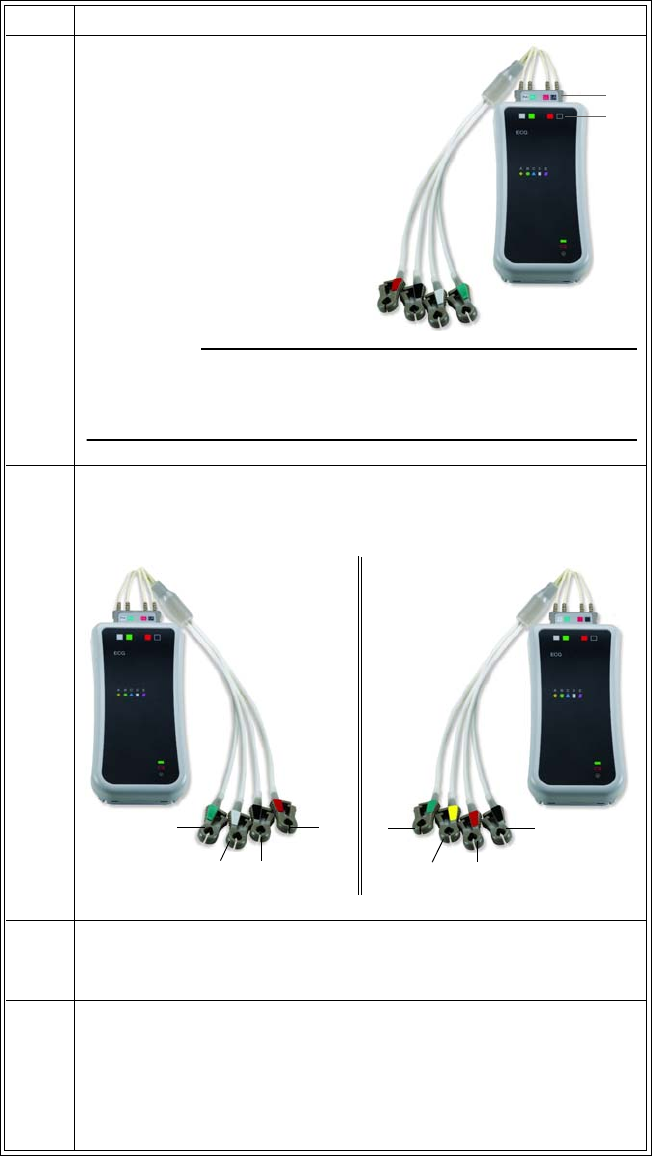
ExpressionMR200InstructionsforUseMonitoringECG4‐9
ToattachtheleadcabletothewECGmoduleandleadcableclipstotheQuadtrodeelectrode
Step Action
1Alignthecolorcodingonthe
leadcableconnector(A)
withcolorcodingonthe
wECGmodule(B)then
inserttheconnectorintothe
module.(AnAHAleadcable
isshownintheexample.)
CAUTION
When inserting or removing the lead cable or clip leads, only use the
connector or clip; never pull or apply excessive force to the wires.
2 DependinguponthetypeoftheECGleadcableandreferencingthe
diagramsonpage4‐8,attachtheECGclipleadstotheQuatrode
electrode.
3 Keepthemoduleoutsidethefieldofview(FOV)byplacingitinone
ofthetwolocationsshowninPositioningthewECGModuleand
LeadCableforScanningonpage4‐11.
4Checkthestatusindicatorofthemodule;seepage2‐8:
• Solidgreen=Batterypowergood/Goodcommunication
• Flashinggreen=Batterypowergood/Nocommunication
• Solidred=Lowbatterypower/Goodcommunication
• Flashingred=Lowbatterypower/Nocommunication
A
B
IEC lead cable
F
LR
N
RL
RA LA
LL
AHA lead cable
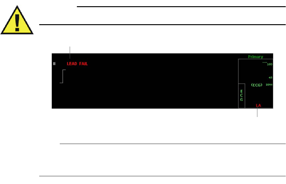
4‐10MonitoringECGExpressionMR200InstructionsforUse
Lead Failure Indication
IfadisconnectedorfaultyQuadtrodeelectrodeorECGleadisdetectedduringmonitoring,the
systemwillimmediatelynotifyyousothatquickactioncanbetakentoidentifythesourceofthe
failureandproceedwithaninformedresponse.Asshownintheexamplebelow,LEADFAILwill
bedisplayedandaredLeadFailindicatorwillappearintheECGVSboxidentifyingthespecific
location(LL,LA,orRA);seepage9‐18fortroubleshootinginformation.
Warning
WARNING
Failure to respond to a Lead Fail alarm will result in a lapse of patient monitoring.
NOTE
If the RL electrode has lost contact (or if all electrodes have lost contact) then LL, LA, RA will be
the displayed indication.
LEAD FAIL indicator
(Example, left arm)
LEAD FAIL message
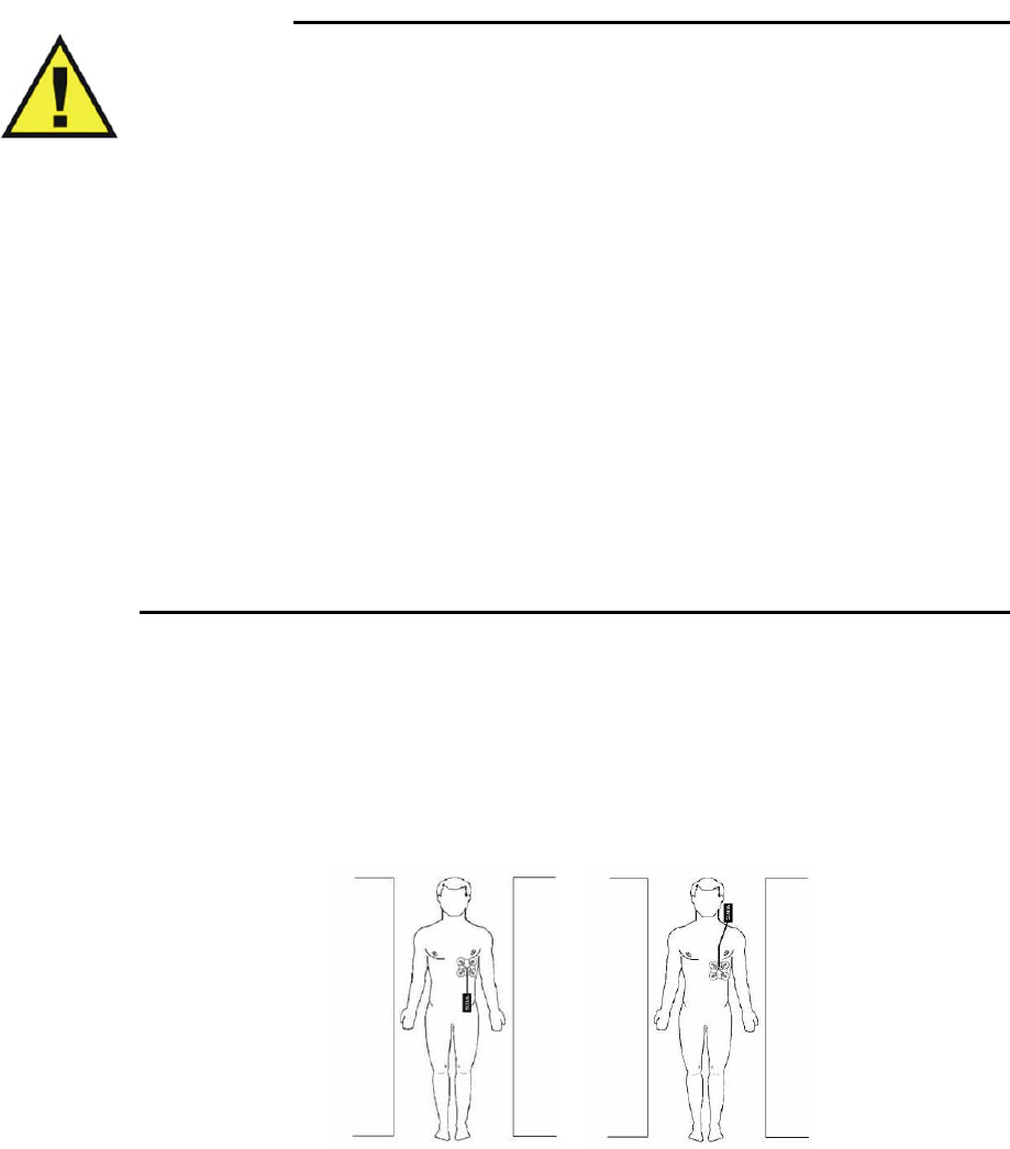
ExpressionMR200InstructionsforUseMonitoringECG4‐11
Positioning the wECG Module and Lead Cable for Scanning
WARNINGS
• When applying electrodes or connecting the patient lead cable, ensure that the
electrodes or connectors never contact other conductive materials including grounded
conductors. In order to prevent contact with other conductors or earth ground, make
sure all the electrodes or connectors are properly attached to the patient.
• No other electrical conductors (e.g. wires, leads, probes, etc.) should be placed within
the MRI bore at the same time as the ECG lead wires. Electrode heating risk increases
when multiple conductive cables and sensors are placed in the bore with the patient.
Mixing of conductors from various manufacturers (catheters, temperature sensors,
etc.) is not recommended. Multiple electrical conductors within the MRI bore can
allow cross-coupling between these various conductors, and appear as a large antenna
for RF energy pick-up, which will result in electrode heating, and possibly skin burns.
It is always important to identify if the patient has any metallic wires, conductors,
implants, stents, etc. within their body which will act as cross-coupling conductors. If
these are present, ECG monitoring may not be able to be performed without
experiencing electrode heating. Non-conductive tubes, air-lines, etc.—including NiBP
cuffs and hoses, EtCO2 and/or oxygen air-lines, and SPO2 sensors—can be used safely
as these items do not include electrically conductive materials. The MR200 has been
validated for use with all accessories specified in the accessory list.
• Circular, U-shaped or S-shaped loops in the patient lead cable should be avoided to
reduce the risk of heating.
ThewECGmodulemaybeusedintheMRsystembore,althoughthemodulemustnotbeplaced
withintheMRIfieldofview(FOV).
LeadcablesmustalwaysbekeptinastraightlineandmustnottouchtheMRsystembore.Any
loop(circular,U‐shaped,S‐shaped)inthecablesorcablecontactwiththeMRsystemborewill
causeheatinginthecablesorinthepatientelectrodes.Followthestepsbelowtominimizethe
cableheatingrisk.
4‐12MonitoringECGExpressionMR200InstructionsforUse
NOTE
Follow these guidelines to ensure the best possible performance of the wECG module, especially
during harsh scan sequences (with PNS-peripheral nerve stimulation-levels above 80 percent):
1. Place the modules on or near the patient as close to the bore iso-center as possible
(considering the scan to be performed).
2. Keep the wireless module outside the field of view.
3. Place the modules as close to the bore opening as possible. (If the modules can be placed
outside the bore, positioning at the bore iso-center is not necessary.)
4. Place the modules on a cushioned surface to minimize MR vibrations.
Warning
WARNING
If the wECG module is positioned incorrectly when used within the MR magnet room, the
following factors may cause ECG waveform distortion and numeric inaccuracies:
• Fast magnetic field changes usually found with, but not limited to, scan sequences
using Peripheral Nerve Stimulation (PNS) levels above 80 percent.
• Severe vibrations induced by scan sequences using PNS levels above 80 percent.
• The distance from the bore iso-center in the x, y, or z directions.
Minimizing the Risk of MRI-Related Heating
CAUTION
Placing the wECG module within the FOV may interrupt ECG monitoring during the MRI
procedure and cause MRI image artifacts.
TominimizetheriskofMRI‐relatedheating
Step Action
1ArrangetheECGleadcableandtheclipleadsneatly,inastraight
alignment,withnolooping.
2Avoidcontactbetweencablesandbareskin.
3UseonlytheECGleadcablesdesignatedforusewiththisproduct;
seepage1‐26.
4 Minimizetheuseofmultiplecables.(Seethewarningsonpage4‐
11fordetails.)
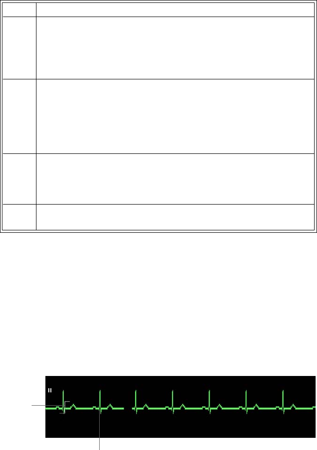
ExpressionMR200InstructionsforUseMonitoringECG4‐13
Checking the ECG Signal Strength
Aminimumsignalstrength(amplitude)shouldbepresent,assmallersignalsmaybeproneto
gradientinterference.EvaluatetheECGsignalproducedbythepatientbeforeentryintotheMRI
scanner,theoptimumtimetocorrectanyproblem.
AproperECGsignalisdeterminedbythepeak‐to‐peakamplitudeoftheQRScomplex.TheQRS
complexshouldbeapproximately2millivoltsonthedisplay(thatis,thesignalshouldbetwice
thesizeofthescaleindicator,a1mVreference,atanygivenSCALEsetting).
Selecting the Scale
TheSCALEsettingonlychangeshowtheECGtraceappearsonthescreen,increasingor
decreasingthewaveformandanyartifacts.ToincreasetheamplitudeoftheQRSComplex,see
ChangingtheLeadViewonpage4‐14.
5ThewECGmodule,ECGleadcablesandQuadtrodeelectrodeare
acceptableforusewithinMRsystemswithstaticmagneticfield
strengthsof3.0TeslaorlesswithintheMRsystemboreusingaMR
systemreportedwholebodyaverageSpecificAbsorptionRates
(SAR)upto4.0W/kg.
6 MonitoringofECGatpowerlevelsofgreaterthanaMRsystem
reported,wholebodyaveragedSARof4W/kgisnotrecommended
forthegeneralpatientpopulation.Suchmonitoringmustonlybe
attemptedwithconsciouspatientswithnormalthermoregulatory
capabilitiessothattheymaywarnyouofpossibleexcessiveheatat
themonitoringsites.
7Usecautionforscantimes(thatis,perpulsesequence)greater
than15minutes.ForMRIscanswithaverageSAR>1W/kg,limit
scantimeto15minutesandpauseatleast3minutesbetween
scanstoallowtheECGelectrodestocool.
8Duringmeasurement,checkthepatienttoensurethatMRI‐related
heatingisnotoccurring.
Step Action
Scale indicator
QRS complex

4‐14MonitoringECGExpressionMR200InstructionsforUse
TochangetheSCALEsetting
Changing the Lead View
IftheQRSComplexdoesnotequalaminimumof2mV,thencompletethefollowingsteps.
Tochangetheleadview
Step Action
1PressthePatientkeyandthenselecttheappropriate
PATIENTtype;seepage3‐10fordetails.
2
TurnthecontrolknobtohighlighttheECGVSbox(seepage4‐18)
andthenpresstheknob.
TheECGmenuappears.Currentsettingsaredisplayed.
3TurnthecontrolknobtoSCALEandthenpresstheknob.
TheSCALEmenuappears;seepage4‐21.
4Turntheknobtoselectthesettingandthenpresstheknob.Onlya
settingof5mm/mVor10mm/mVisrecommended.
AUTO
1mm/mV
5mm/mV
10mm/mV
15mm/mV
20mm/mV
25mm/mV
30mm/mV
40mm/mV
Thesettingisapplied.
5Takenoteofthescaleindicator;seepage4‐16.Iftheselectedscale
resultsinanECGtracesolargethatthewaveformpeaksare
distortedorclipped,OVERSCALEwillbedisplayed.Inthiscase,
selectanothersettingtoresizethewaveformuntilthemessage
stops.
Step Action
1VerifytheQuadtrodeelectrodedate,qualityandpackaging.
2EnsurethatthepreferredQuadtrodeelectrodeandplacement
site(s)arebeingused;seepage4‐4.

ExpressionMR200InstructionsforUseMonitoringECG4‐15
Selecting the Filter Mode
ChoosetheappropriateECGfiltermodeforyourMRIstudy.
Tochangethefiltermodesetting
3TurnthecontrolknobtohighlighttheECGVSbox(seepage4‐18)
andthenpresstheknob.
TheECGmenuappears.Currentsettingsaredisplayed.
4 Dependinguponthetracebeingexamined,turnthecontrolknobto
TRACEALEADorTRACEBLEADandthenpresstheknob.
Therespectivemenuappears;seepage4‐20or4‐20.
5Changethesettingtoadifferentleadviewtoaccountforpatient
variabilityandthenpresstheknob.
I
II
III
AVL
AVR
AVF
Theleadviewchanges;seepage4‐16.
NOTE
When presented with a low QRS amplitude from ECG or poor
gating, it may be necessary to use the PEDIATRIC ECG setting;
see page 3-11.
6Iftheamplitudedidnotimprove,cyclethroughtheremaininglead
viewstoafindthebestsignalamplitudebyrepeatingstep5.
7Iftheamplitudedoesnotimprove,removetheleadcableand
Quadtrodeelectrodeandthenpreptheapplicationsiteagain.
Step Action
Step Action
1TurnthecontrolknobtohighlighttheECGVSbox(seepage4‐18)
andthenpresstheknob.
TheECGmenuappears.Currentsettingsaredisplayed.
2TurnthecontrolknobtoFILTERMODEandthenpresstheknob.
TheFILTERMODEmenuappears;seepage4‐23.
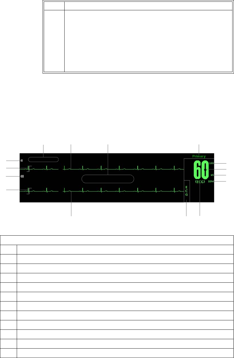
4‐16MonitoringECGExpressionMR200InstructionsforUse
ECG Waveforms and VS Box
TheelementscontainedinthedisplayedECGwaveform(TraceA,andBifenabled)andVSbox
aredescribedbelow:
3Turntheknobtoselectthefilterandthenpresstheknob.
MONITOR
PRIMARY
SECONDARY
CARDIAC
ADVANCED
Thesettingisapplied,asindicatedabovetheECGVSbox.
Step Action
Definition
1 Is the high limit setting of the HR (heart rate) alarm; see page 4-19
2 Is the heart rate measurement (numeric)
3 Is the low limit setting of the HR alarm; see page 4-19
4 Is the unit of measure for the heart rate, where BPM is beats per minute
5 Is the selected HR SOURCE; see page 4-22
6 Is the name of the vital sign
7 Is the detected ECG Trace B waveform
8 Is the scale indicator, a 1-millivolt signal reference (see SCALE on page 4-21)
9 Is the selected TRACE B LEAD; see page 4-20
10 Same as 8, above
11 Is the selected TRACE A LEAD; see page 4-20
12 Displays LEAD FAIL when detected; see the example on page 4-10
1
2
3
6
8
9
7
10
5
11
12 13 14 15
4

ExpressionMR200InstructionsforUseMonitoringECG4‐17
Changing the Waveform Speed
TochangetheECG(andSPO2)waveformspeed
Changing the Heart Rate Alarm Limits
Tochangetheheartratealarmlimitsettings
13 Is the detected ECG Trace A waveform
14 Displays messages; see page 9-16 for details
15 Is the selected FILTER MODE; see page 4-23
Definition
Step Action
1PresstheSETUPkey.
TheSETUPmenuappears.
2TurnthecontrolknobtoMONITORSETUPandthenpresstheknob.
TheMONITORmenuappears.Currentsettingsaredisplayed.
3TurntheknobtoSWEEPSPEEDandthenpresstheknob.
TheSWEEPSPEEDmenuappears;seepage3‐14.
4Turnthecontrolknobtoselecteitherofthefollowingsettingsand
thenpresstheknob:
50mm/s
25mm/s
Theselectionisentered.
Step Action
1TurnthecontrolknobtohighlighttheECGVSbox(seepage4‐18)
andthenpresstheknob.
TheECGmenuappears.Currentsettingsaredisplayed.
2TurnthecontrolknobtoALARMLIMITSandthenpresstheknob.
TheALARMLIMITSmenuappears.Currentsettingsaredisplayed;
seepage4‐19fordetails.
3Turntheknobtothel
oworhigh
settingandthenpresstheknob.
Thesettingisselected.
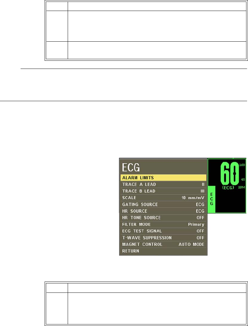
4‐18MonitoringECGExpressionMR200InstructionsforUse
NOTE
To make global changes to the parameter alarm limit settings based upon the patient’s current
vital sign readings, see Setting Alarm Limits Globally on page 9-4.
ECG Menu
TheECGmenuallowsyoutocontrolECG
traces,functionsandsettings.
TochangesettingsintheECGmenu
4Turntheknobtochangethesettingvalueandthenpresstheknob
tomakethechangeeffectiveandreturntothescrollingfunction.
Thesettingischanged.
5Tochangetheremainingsetting,repeatsteps3and4.
Step Action
Step Action
1TurnthecontrolknobtohighlighttheECGVSboxandthenpress
theknob.
TheECGmenuappears.Currentsettingsaredisplayed.
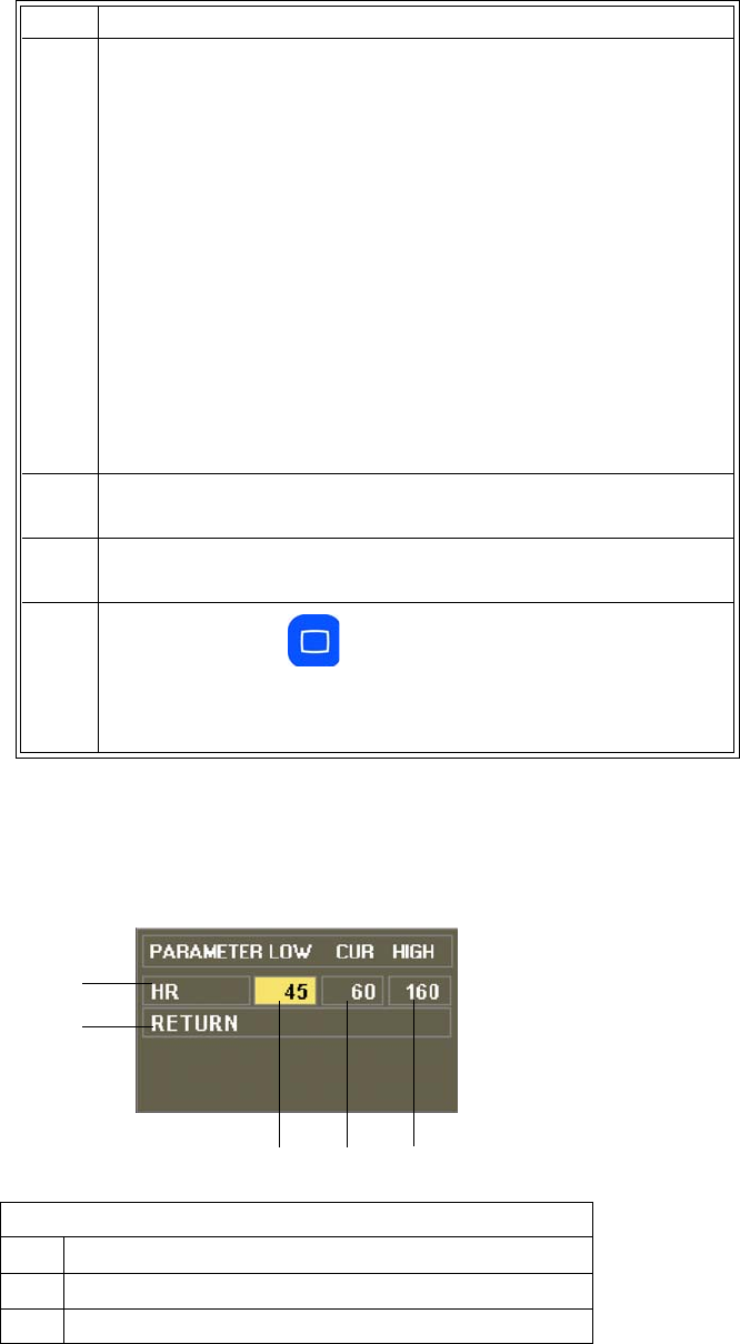
ExpressionMR200InstructionsforUseMonitoringECG4‐19
ALARM LIMITS
Controlsthealarmlimitsettingsforheartrate.(Seethetableonpage9‐15foralisting.)
2TurnthecontrolknobtoselectanyofthefollowingECGoptions:
ALARMLIMITS
TRACEALEAD
TRACEBLEAD
SCALE
GATINGSOURCE
HRSOURCE
HRTONESOURCE
FILTERMODE
ECGTESTSIGNAL
T‐WAVESUPPRESSION
MAGNETCONTROL
Forinformationabouttheseoptions,seetheappropriatesections
below.
3Turntheknobtothedesiredsettingandthenpresstheknob.
4Tochangeothersettings,repeatsteps2and3.
5PresstheMainkeytoclosethemenu.
Alternative:TurntheknobtoRETURNandthenpresstheknob,or
waitapproximately60seconds.
Definition
1 Is the setting of the high alarm limit
2 Is the current measurement
3 Is the setting of the low alarm limit
Step Action
12
3
4
5

4‐20MonitoringECGExpressionMR200InstructionsforUse
Tosetanalarmlimitforheartrate
SeeChangingtheHeartRateAlarmLimitsonpage4‐17.
TRACE A LEAD
SetstheECG A leadconfiguration.ForbestECGandheartratemonitoring,alwaysselectthe
optimalleadconfiguration,theonethatprovidestheleastartifactandlargestwaveform
detectionformonitoringuse.
Thefollowingchoicesareavailable:
•I
•II(Default)
•III
•AVL
•AVR
•AVF
•OFF
TosettheECGAlead
SeeChangingtheLeadViewonpage4‐14.
TRACE B LEAD
SetstheECG B leadconfiguration,allowingyoutoviewtwoECGwaveformssimultaneously.
Thefollowingchoicesareavailable:
•I
•II
•III
•AVL
•AVR
•AVF
•OFF(Default)
4 Saves the settings then returns to the normal mode
5 Identifies heart rate alarm limits
Definition

ExpressionMR200InstructionsforUseMonitoringECG4‐21
TosettheECGBlead
SeeChangingtheLeadViewonpage4‐14.
SCALE
SetsthescalefortheECG waveforms.Aftermakingthissetting,takenoteofthescaleindicator;
seepage4‐16.Iftheselectedscaleresultsinawaveformwithdistortedorclippedpeaks,
OVERSCALEwillbedisplayedandanothersettingshouldbeselecteduntilthemessagestops.
Thefollowingchoices(inmillimeterspermillivolt)areavailable:
•AUTOmakesthewaveformfilltheECGtracearea(notrecommendedforuseintheMR).
•1mm/mV
•5mm/mV
•10mm/mV(Default)
•15mm/mV
•20mm/mV
•25mm/mV
•30mm/mV
•40mm/mV
TosettheECGscale
SeeSelectingtheScaleonpage4‐13.
NOTE
This setting does not affect the signal analyzed by the monitor for QRS detection and ECG gating.
GATING SOURCE
Setsthecardiacgatingsourcebasedonameasuredsignal.(Thisisthesameoptionasinthe
SPO2menu.)
Thefollowingchoicesareavailable:
•ECGareoutputsthatrepresentthedetectionoftheR‐peakofaQRScomplex,asignalthe
MRsystemcanusedirectlyfortriggering.(Default)
•PULSEaresignalsthatrepresentthedetectionofthepeakoftheperipheralpulsecomplex.
Tosetthegatingsource
SeeUsingtheGatingFeatureonpage4‐26.

4‐22MonitoringECGExpressionMR200InstructionsforUse
NOTE
Trace A is the default output channel for interfacing the cardiac gating input. To use Trace B, set
Trace A to off, and ensure that Trace B is active (that is, not off); see page 4-20.
HR SOURCE
Selectsthesourcethatproducestheheartrate,asdisplayedintheECGVSbox(identicaltoand
interactivewiththesameoptionintheSPO2menu).
Thefollowingchoicesareavailable:
•AUTOselectsthesourceautomaticallyfromthehighestpriorityactiveinput,wherethe
MR200searchesforanothersourceonlywhenLEADFAILoccursorwhenECGisoff.Ifthe
highestpriorityinputisnotfound,thenextrankedparameterissought.Thepriority
rankingisECGandthenSPO2.Ifnoparameterspresentaheartrate,thenNONEis
displayedintheheartrateposition.
•ECG(Default)
•SPO2
Tosettheheartratesource
HR TONE SOURCE
Setsthesourceusedfortheheartratetone(identicaltoandinteractivewithsameoptioninthe
MONITOR>SOUNDADJUSTmenuandintheSPO2menu).
Step Action
1TurnthecontrolknobtohighlighttheECGVSbox(seepage4‐18)
andthenpresstheknob.
TheECGmenuappears.Currentsettingsaredisplayed.
2TurnthecontrolknobtoHRSOURCEandthenpresstheknob.
TheHRSOURCEmenuappears.
3Turnthecontrolknobtoselectoneofthefollowingoptionsand
thenpresstheknob:
AUTO
ECG
SPO2
Thesettingischanged.

ExpressionMR200InstructionsforUseMonitoringECG4‐23
Thefollowingchoicesareavailable:
•OFFremovestheheartsymbolfromthedisplayandnopulsetonewillbesounded.
(Default)
•QRSprovidesatonetriggeredbytheQRSdetectionfromtheECGvitalsign.
•SPO2providesatonemodulatedbytheSPO2vitalsign,wherethelowertheSPO2value,
thelowerthepitch.
Tosettheheartratetonesource
EntertheECGmenu.TurnthecontrolknobtoHRTONESOURCEandpresstheknob.Scrolltothe
desiredsettingandpresstheknob.(Seepage3‐9fordetailedinstructions.)
FILTER MODE
SetsthefilteringmodefortheECGsignal.
NOTES
• Due to the variety of MRI sequence characteristics, if the filter recommendations below do
not provide optimum performance in all cases, the selection of another filter mode may
improve ECG performance.
• ECG performance can be affected by electrode placement, the MRI procedure, the image
slice angle and slice thickness. In situations where ECG performance is not optimal, select
the ECG lead (I, II, III, AVL, AVR, or AVF) that provides the best performance.
• For cases not requiring cardiac gating, start with the Primary filter mode (depending on the
MRI sequence) and switch filters if a gradient artifact is noticed. If a gradient artifact is still
present, check signal strength and try lead I or III.
Thefollowingchoicesareavailable:
•MONITORprovidesfilteringcharacteristicsthatmeetthespecificationoftheAssociation
fortheAdvancementofMedicalInstrumentation(AAMI).Notethatthisfilterwillnot
provideoptimumperformanceduringactiveMRIsequences.
•PRIMARYprovidesthebestpossibleperformanceon0.15to3.0TMRsystemsduringEcho
TraintypeMRIsequences.(Default)
•SECONDARYprovidesthebestpossibleperformanceon0.15to3.0TMRsystemsduring
mostnon‐cardiovascularMRIsequences.
•CARDIACprovidesthebestpossibleperformanceduringcardiovascular(CV)MRI
proceduresthatinvolvesteady‐statefreeprecessionimagingwithbalancedgradient(True‐
FISP,FIESTA,orBalancedFFE)sequenceson1.5and3.0TMRsystems.Forcasesrequiring
cardiacgating,startwiththeCardiacfilterinleadIIandswitchfiltersifgradientartifactis
noticed.Ifgradientartifactisstillpresent,checksignalamplitudeandtryleadIorIII.
•ADVANCEDprovidesthebestpossibleperformanceon1.5and3.0TMRsystemsduring
MRIsequencessuchasneurologicalandcardiovascular.ThisMRIfilterutilizesanadaptive
filterschemeforremovalofgradientartifactgeneratedbyMRsystems. Bestperformance

4‐24MonitoringECGExpressionMR200InstructionsforUse
isachievedusingtheAdvancedFilterECGleadcable,whichallowsplacementofthewECG
moduleoutsideofthebore.
Advancedfilteringoperatesononeleadatatimefromarestrictedsetofleadsandcannot
beappliedtoAVR,AVLorAVFleads.Toprovidethemostconvenienttransitiontothis
filterandleadconfiguration,thesystemwillautomaticallyselecttheleadtouseby
applyingthefollowingrulesintheordershownbelow:
1. IfTraceAisdisplayed,thecurrentlyselectedleadonTraceAwillbeusedbutonlyifit
isleadI,IIorIII.
2. IfTraceBisdisplayed,thecurrentlyselectedleadonTraceBwillbeusedbutonlyifit
isleadI,IIorIII.
3. Ifneitherrule1norrule2apply,thenleadIIwillbeused.
ThesystemdisplaystheselectedleadonTraceAanddisablesdisplayofTraceB.Youcan
changewhichleadisfiltered,whiletheADVANCEDfilteroperatesbychanginglead
selectionforTraceA.However,onlyleadsI,IIandIIIwillbeavailablewhiletheADVANCED
filterisengaged.(TodeselectADVANCED,selectadifferentfilteroptionfromthemenu.
Thedisplaywillremainunchanged;however,TraceBcanbere‐enabledatthispointif
desired.)
Tosetthefiltermode
SeeSelectingtheFilterModeonpage4‐15.
ECG TEST SIGNAL
GeneratesanECGcalibrationwaveform.
Thefollowingchoicesareavailable:
•OFFturnsthecalibrationfeatureoff.(Default)
•PRINTERsendsa1mVpulsecalibrationwaveformtotheECGvitalsignandalsotothe
printer,ifsoconfigured,whereECGTESTSIGNALwillbeprintedbelowthewaveform.
•ECGsendsawECGmodulegenerated1mVpeaktopeakcalibrationsquarewavetothe
ECGvitalsignandalsototheprinter,ifsoconfigured,whereECGTESTSIGNALwillbe
superimposedoverthewaveformand60BPMwillbedisplayedintheECGVSbox.
TogeneratetheECGtestsignal
EntertheECGmenu.TurnthecontrolknobtoECGTESTSIGNALandpresstheknob.Scrolltothe
desiredoutputandpresstheknob.
NOTES
• Available on all lead configurations, except Lead III.
• Unavailable when FILTER MODE is set to ADVANCED.
• Automatically set to off during interoperability; see GATING SOURCE on page 4-21.

ExpressionMR200InstructionsforUseMonitoringECG4‐25
T-WAVE SUPPRESSION
ReducestheT‐waveamplitudewhenextremelylargeduetothemagnetohydrodynamiceffect
(MHD),whichcanpreventgating.UseforaccurategatingwhenanunusuallyhighT‐wave
amplitude,relativetotheR‐waveamplitude,isseen.
Thefollowingchoicesareavailable:
•OFF(Default)
•ON
ToapplyT‐wavesuppression
EntertheECGmenu.TurnthecontrolknobtoT‐WAVESUPPRESSIONandpresstheknob.Scroll
tothedesiredsettingandpresstheknob.
NOTES
• Unavailable when FILTER MODE is set to MONITOR; see page 4-23.
• Controlled by the gating box through the wECG module during interoperability; see
GATING SOURCE on page 4-21. With the wBTU, T-WAVE SUPPRESSION will be set
to off; and, with other OEM gating boxes, it will be set as it is in the gating box.
MAGNET CONTROL
RemovesgradientartifactsoncertainMRsystemsequippedwithvectorECG
gating.Onthesesystems,onlyonewECGmoduleneedstobeconnectedto
thepatientinorderfortheMR200andtheMRsystemtomonitorthe
patient'svitalsignsandgatethemagnet.
Thefollowingchoicesareavailable:
•AUTOMODEallowstheMRsystemtowork,ifcapable,withtheMR200
toeffectivelyremovegradientartifactsfromtheECGwaveform.When
selectedandwiththewECGmoduleinradiocontactwiththeMR
system,FILTERMODE,T‐WAVESUPPRESSIONandECGTESTSIGNAL
willbedisabledandlocked.(Default)
MAGNETCONTROLwillbedisplayedtoindicatethatfiltermode
selectionhasbeenpreemptedbytheMRsystem.Inaddition,ifHR
SOURCEissettoECG,theheartrateasderivedfromtheMRsystemwill
bedisplayed(abriefinterruptioninthedisplayedwaveformispossible)
andMAGNETFILTERwillbedisplayed.
IftheMR200orthewECGmoduleceaseradiocontactwiththeMR
system,theMR200willresetitsfilterandT‐wavesuppressionoptions
tothesettingsheldpriortocontactwiththeMRsystem.

4‐26MonitoringECGExpressionMR200InstructionsforUse
NOTE
FILTER MODE and T-WAVE SUPPRESSION settings will not be recalled when in MAGNET
CONTROL or MAGNET FILTER mode. And, if a system recall is performed and then the
MR200 is moved from the MR environment, the filter and T-wave suppression options will revert
to their previous settings.
•DISABLEDallowstheMR200tocontrolfilteringandT‐wavesuppression.
Toallowmagnetcontrol
EntertheECGmenu.TurnthecontrolknobtoMAGNETCONTROLandpresstheknob.Scrollto
thedesiredsettingandpresstheknob.
Using the Gating Feature
ThegatingfeatureprovidesfacilitiesforlowlatencyMRItriggeringandsynchronizationbasedon
themeasuredECGorSPO2signal.DatameasuredandtransmittedbythewECGorwSPO2
moduleisprocessedbytheMR200andthenoutputfromthegatingconnector;seepage1‐16for
thelocation,andseepageA‐11forsignaldetails.(Signalscanalsotransmittedbytheoptional
wBTU.)
Using ECG Gating
ToreceiveECGgatingsignals
Step Action
1VerifythewECGmodulestatusbycheckingthestatusindicator:
• Solidgreen=BatterypowerOK/Goodcommunication
• Flashinggreen=BatterypowerOK/Nocommunication
• Solidred=Lowbatterypower/Goodcommunication
• Flashingred=Lowbatterypower/Nocommunication
2Ensurethattheleadcableisproperlyattachedtothepatient;see
AttachingtheLeadCableonpage4‐8.
(ECGoutputsareenabledbydefault;seepage4‐21.)

ExpressionMR200InstructionsforUseMonitoringECG4‐27
Using SPO2 Gating
ToreceiveSPO2gatingsignals
Step Action
1VerifythewSPO2modulestatusbycheckingthestatusindicator:
• Solidgreen=BatterypowerOK/Goodcommunication
• Flashinggreen=BatterypowerOK/Nocommunication
• Solidred=Lowbatterypower/Goodcommunication
• Flashingred=Lowbatterypower/Nocommunication
2EnsurethattheSPO2attachmentisproperlyattached;seeApply‐
ingtheSPO2AttachmenttothePatientonpage5‐3.
3TurnthecontrolknobtohighlighttheSPO2VSbox(seepage5‐7)
andthenpresstheknob.
TheSPO2menuappears.Currentsettingsaredisplayed.
4TurnthecontrolknobtoGATINGSOURCEandthenpresstheknob.
TheGATINGSOURCEmenuappears;seepage5‐12.
5TurntheknobtoPULSEandthenpresstheknob.
Thesettingisapplied.

4‐28MonitoringECGExpressionMR200InstructionsforUse

ExpressionMR200InstructionsforUseMonitoringSPO25‐1
CHAPTER 5
Monitoring SPO2
Thepulseoximetryfeatureusesamotion‐tolerantsignalprocessingalgorithmbasedonFourier
ArtifactSuppressionTechnology(FAST)toprovideoxygenatedhemoglobinmeasurements,a
visualpulseindicationandapulserate,specifically:
•Oxygensaturationofarterialblood(SPO2):Thepercentageofoxygenatedhemoglobinin
relationtothesumofoxyhemoglobinanddeoxyhemoglobin(functionalarterialoxygen
saturation).
• Plethysmography(pleth)waveform:Avisualindicationofthepatient’spulsatileblood
flow.
•Pulserate(asderivedfromtheplethwaveform):Thenumberofdetectedpulsationsper
minute.
NOTE
A pulse oximeter should be considered an early warning device. As a trend toward patient
deoxygenation is indicated, blood samples must be analyzed by a laboratory co-oximeter to
understand the patient’s condition completely.
wSPO2 Module, Sensor and Attachment
ThewSPO2module,sensorandattachment(cliporgrip)areintendedforpatientuseswhen
continuousnon‐invasivearterialoxygensaturation,pulseratemonitoringorpulsegatingare
required.ThewSPO2module,sensorandattachmentmaybeusedintheMRsystembore,
althoughthemodulemustnotbeplacedwithintheMRIfieldofview(FOV).
CAUTION
If dropped, the wSPO2 module must be verified for correct operation before use.
NOTE
Refer to your facility's biohazard procedure for disposal of SPO2 attachments and sensors when
they become unusable. Usually sensors are disposed of as medical waste per facility procedures.
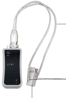
5‐2MonitoringSPO2ExpressionMR200InstructionsforUse
Patient Preparation for SPO2 Monitoring
WhenmonitoringSPO2,thesiteselectedonthepatient,theSPO2attachment,theattachment’s
positiononthepatient,andtheambientenvironmentwillimpacttheperformanceand
operationoftheparameter.
Selecting the Site and Attachment
Whenapplyingtheclipsorgripstothepatient,sitepreparationandthepressureandalignment
oftheattachmentareimportantfactorstoconsider.Selectthemostappropriatelimbthatbest
fitstheattachmentsize.Formeasurementstobeaccurateandreliable,theoptimumfitis
reachedwhenthefiberheadwindowsopposeeachotherandarecoveredbyskinornail.Refer
totheinstructionsprovidedwiththeattachmentwhenselectingandconnectingthecliporgrip.
Attaching the Clip or Grip to the SPO2 Sensor
Toattachtheclips(orgrips)totheSPO2sensor
SnapthefiberheadsontheSPO2sensorintothe
receptacles(windows)ontheSPO2attachment
(cliporgrip).
SPO2 sensor
SPO2 attachment (clip
shown)
Fiber heads
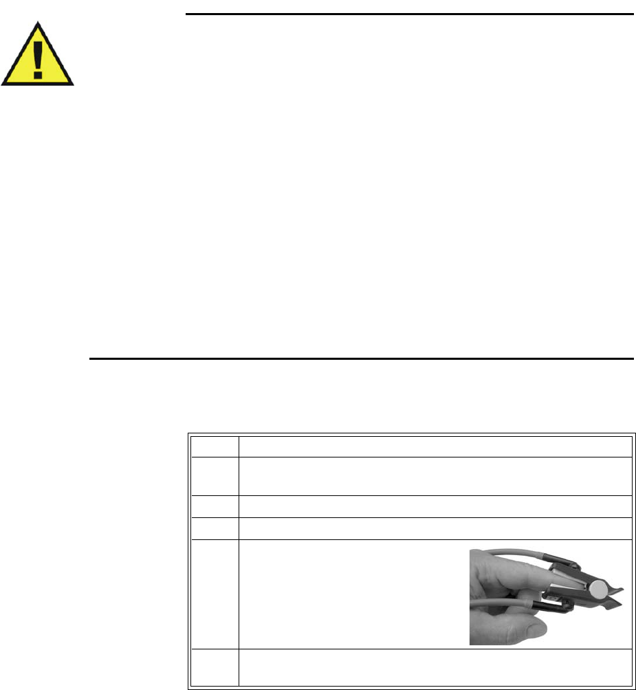
ExpressionMR200InstructionsforUseMonitoringSPO25‐3
Applying the SPO2 Attachment to the Patient
ReadthewarningsbeforeapplyinganSPO2attachmenttothepatient.
WARNINGS
•General fit: If a clip or grip is too loose, it might compromise the optimal alignment or
dislocate. If the clip or grip is too tight (for example, if the application site is too large
or becomes large due to edema), excessive pressure may be applied resulting in venous
congestion distal from the application site, which could lead to interstitial edema,
hypoxemia, tissue malnutrition, and inaccurate measurements. Skin irritations may
occur as a result of the clip or grip being attached to one location for too long.
Periodically inspect the clip or grip application site and change the application site at
least every 4 hours. Exercise care when using tape to secure the clip or grip, as the
stretch memory properties of most tapes can apply unintended pressure to the site
easily.
• Extremities to avoid: Avoid placing the clip or grip on extremities with an arterial
catheter, intravascular venous infusion line, or inflated blood pressure cuff. Failure to
do so may result in inaccurate readings or false alarm indications.
• Protect the sensor from contact with any liquid. If the sensor, clips or grips show signs
of damage like exposed fibers, replace the part immediately. Do not use damaged
equipment.
• Keep detached grips and clips away from small children to avoid possibility of
swallowing.
Toapplyareusablecliptothepatient
Step Action
1 Selecttheapplicationsite.Itshouldmatchtheclipsizesothatthe
sensordoesnotfallofforapplyexcessivepressureatthesite.
2Ifpresent,removeanycolorednailpolishfromtheapplicationsite.
3Pressthecliptoopen.
4Pushtheclipoverafingersoeither
fiberheadisonthetopovertheroot
ofthenailandtheotherfiberhead
oppositetoit.(Itdoesnotmatter
whichheadisontop.)
5Ensurethatthefingeristouchingthestopatthecushionandlays
nicelycenteredintheclip.
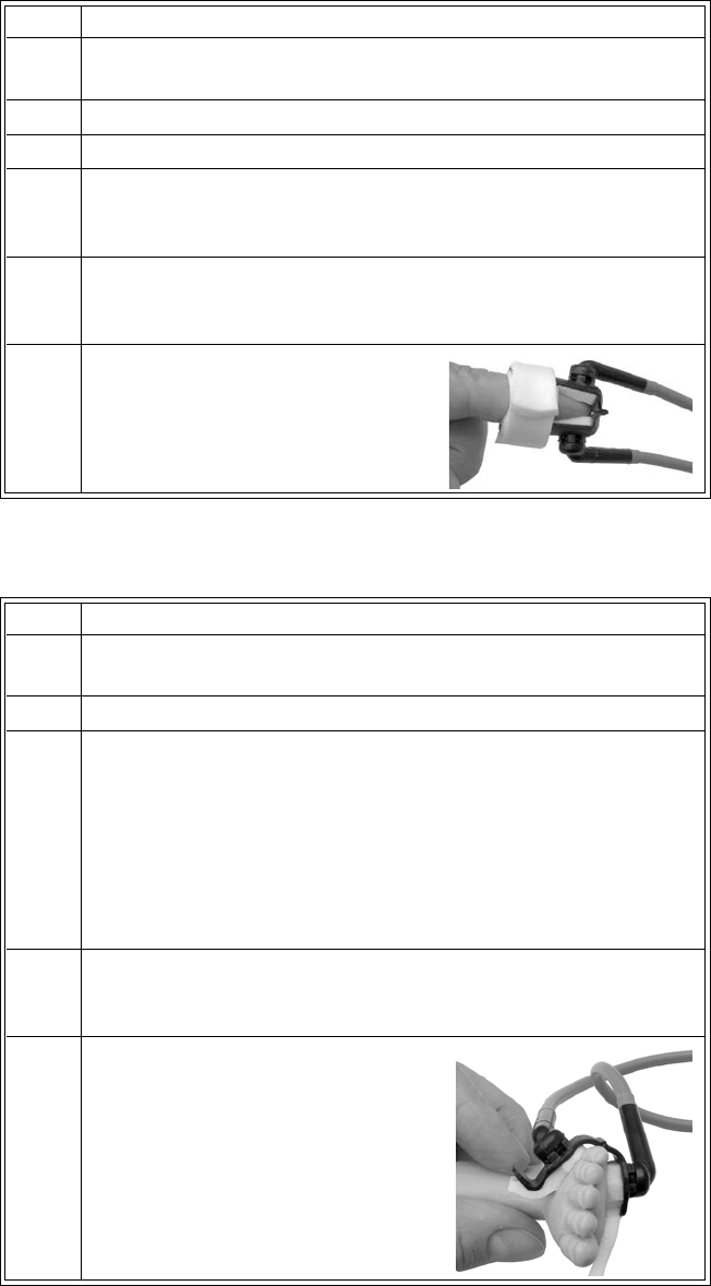
5‐4MonitoringSPO2ExpressionMR200InstructionsforUse
Toapplyadisposablecliptothepatient
Toapplyadisposableneonatecliptothepatient
Step Action
1 Selecttheapplicationsite.Itshouldmatchtheclipsizesothatthe
sensordoesnotfallofforapplyexcessivepressureatthesite.
2Ifpresent,removeanycolorednailpolishfromtheapplicationsite.
3Liftoffthereleaselinersthatprotecttheadhesive.
4Putthefinger(ortoe)ontoeithersideoftheattachment‐theyare
symmetrical‐suchthatthetipcoversthewindowcompletelyand
doesnotprotrudeoverthehinge.
5Closethegrip.Ifthefitisgood,presstheattachmentfirmlyonthe
fingerortoe.Ifthefitisnotgood,repositiontheattachment.Make
surethelimbiscenterednicelyintheattachment.
6Wrapthefoamwingsaroundthe
fingerandattachmentandstickto
theopposinggripside.Donotstretch
thefoamtoapplyexcessivepressure.
Step Action
1 Selecttheapplicationsite.Itshouldmatchtheclipsizesothatthe
sensordoesnotfallofforapplyexcessivepressureatthesite.
2Liftoffthereleaselinersthatprotecttheadhesive.
3 Proceedaccordingtotheapplicationsite:
• Footapplication:Alignthehingeontheoutsidefacingridge
ofthefoot.Makesuretheattachmentisasfaraspossible
towardthesmalltoebutnotoverit.
•Hand/Wristapplication:Alignthehingeontheoutsidefacing
ridgeofthehandorwrist.Youmayhavetoswivelthefiber
headstoanoptimalpositiontoeasetheapplication.
4Withthehingealignedwiththeridgeofthefoot/hand/wrist,press
onesidetotheskinandthenwraptheothersidearoundthelimb
pullingthelongfoampiecegently.
5Pressbothfiberheadsgentlytoattach
theadhesives.
ExpressionMR200InstructionsforUseMonitoringSPO25‐5
WARNING
Disposable attachments are designed for single patient use and must be
disposed after use. They must not be cleaned and reused. Follow your hospital’s
guidelines for appropriate disposal. Reuse of single-use devices can result in
spread of patient infection, degradation of monitoring performance, or
inaccurate measurements.
Positioning the wSPO2 Module for Scanning
Toensurethebestperformance,specificpositioningconsiderationsarerequiredwhenusingthe
wSPO2moduleintheMRmagnetroom,includingharshscansequenceswithperipheralnerve
stimulationlevelsabove80percent.
WARNING
If the wSPO2 module is incorrectly positioned when used within the MR magnet room, the
following factors can cause SPO2 waveform distortion and numeric inaccuracies, and
respiration numeric inaccuracies:
• Fast magnetic field changes usually found but not limited to scan sequences using PNS
levels above 80 percent.
• Severe vibrations induced by scan sequences using PNS levels above 80 percent.
• Distance from the bore opening.
• Distance from the bore iso-center in the x, y, or z direction.
ToensurebestperformanceduringSPO2measurements
6Securethelongerfoampiecebypressingitfirmlytothefoam/
adhesiveoftheopposingside.
7Ensurethatthetwofiberheadsareopposingandhavegoodskin
contact.Theanglebetweenthetwofiberheadsshouldbeassmall
aspossible,notexceeding45°.Iftheattachmentopenstoomuch,
reattachortryanothersite.
Step Action
Step Action
1Ensurethatthefiberheads(thelightemitterandthe
photodetectorinthecliporgrip)aredirectlyoppositeeachother,
asthelightmustpassthroughthepatient’stissueandbereceived
forproperoperation.
2Swiveleachfiberheadintoapositionthatcausestheleastbending
ofthecablewhileprovidingthemostcomforttothepatient.
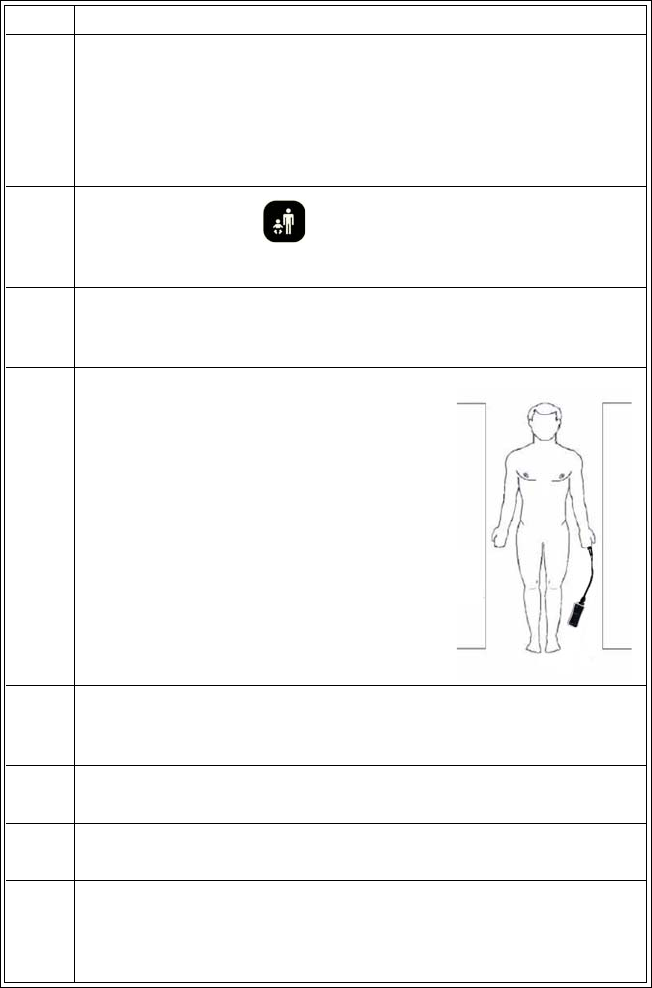
5‐6MonitoringSPO2ExpressionMR200InstructionsforUse
3VerifythewSPO2modulestatusbycheckingthestatusindicator:
• Solidgreen=BatterypowerOK/Goodcommunication
• Flashinggreen=BatterypowerOK/Nocommunication
• Solidred=Lowbatterypower/Goodcommunication
• Flashingred=Lowbatterypower/Nocommunication
4
PressthePatientkeyandthenselecttheappropriate
PATIENTtype;seepage3‐10fordetails.
5CheckforanydisplayedSPO2messagesand,ifamessageis
present,followtherecommendedactiontoachievebetterresults
(seepage9‐16).
6Whileconsideringthescantobe
performed,placethewSPO2moduleonor
nearthepatientandascloseaspossibleto
theboreopening.Keepthesensorand
moduleoutsidethefieldofview.
7Placethemoduleascloseaspossibletotheboreopening.(Ifthe
modulecanbeplacedoutsidethebore,positioningattheiso‐
centerisnotnecessary.)
8PlacethemoduleonacushionedsurfacetominimizeMR
vibrations.
9Covertheattachmentsiteonthepatientwithopaquematerial.
10
Duringmeasurement,checkthepatienttoensurethatthe
applicationsitehasapulsatileflowandthatthesitehasnot
changedinthickness(forexample,duetoedema)causingan
improperfit.
Step Action
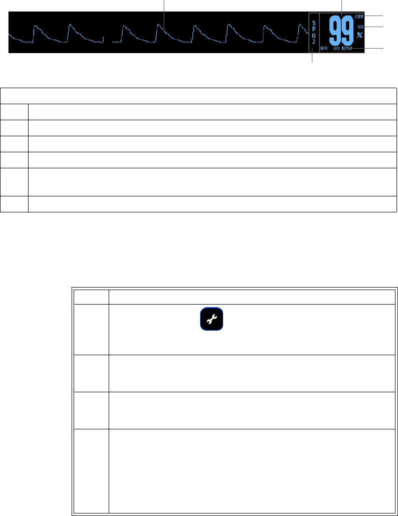
ExpressionMR200InstructionsforUseMonitoringSPO25‐7
SPO2 Waveform and VS Box
TheelementscontainedintheSPO2waveform(TraceC)andVSboxaredescribedbelow:
Changing the Waveform Speed
TochangetheSPO2(andECG)waveformspeed
Definition
1 Is the high limit setting of the SPO2 alarm; see page 5-10
2 Is the low limit setting of the SPO2 alarm; see page 5-10
3 Is the heart rate numeric and the unit of measure, where BPM is beats per minute.
4 Is the name of the vital sign
5 Is the detected SPO2 waveform, not proportional to pulse volume and can be
amplitude-adjusted for viewing; see page 5-8.
6 Is the SPO2 measurement (numeric), given as a percentage
1
2
3
4
56
Step Action
1PresstheSETUPkey.
TheSETUPmenuappears.
2TurnthecontrolknobtoMONITORSETUPandthenpresstheknob.
TheMONITORmenuappears.Currentsettingsaredisplayed.
3TurntheknobtoSWEEPSPEEDandthenpresstheknob.
TheSWEEPSPEEDmenuappears;seepage3‐14.
4Turnthecontrolknobtoselecteitherofthefollowingsettingsand
thenpresstheknob:
50mm/s
25mm/s
Theselectionisentered.

5‐8MonitoringSPO2ExpressionMR200InstructionsforUse
Changing the SPO2 Waveform Amplitude
TochangetheSPO2waveformamplitude
Changing the SPO2 Alarm Limits
TochangetheSPO2alarmlimitsettings
NOTE
To make global changes to the parameter alarm limit settings based upon the patient’s current
vital sign readings, see Setting Alarm Limits Globally on page 9-4.
Step Action
1
TurnthecontrolknobtohighlighttheSPO2VSbox(seepage5‐9)
andthenpresstheknob.
TheSPO2menuappears.Currentsettingsaredisplayed.
2
TurnthecontrolknobtoSIZEandthenpresstheknob.
TheSIZEmenuappears;seepage5‐11fordetails.
3Turn
thecontrolknobtoselectoneofthefollowingoptionsand
thenpresstheknob:
10,20,40,60,80or100percent
Thesettingischanged.
Step Action
1
TurnthecontrolknobtohighlighttheSPO2VSbox(seepage5‐9)
andthenpresstheknob.
TheSPO2menuappears.Currentsettingsaredisplayed.
2
TurnthecontrolknobtoALARMLIMITSandthenpresstheknob.
TheALARMLIMITSmenuappears.Currentsettingsaredisplayed;
seepage5‐10fordetails.
3
Turntheknobtothel
oworhigh
settingandthenpresstheknob.
Thesettingisselected.
4
Turntheknobtochangethesettingvalueandthenpresstheknob
tomakethechangeeffectiveandreturntothescrollingfunction.
Thesettingischanged.
5Tochangetheremainingsetting,repeatsteps3and4.
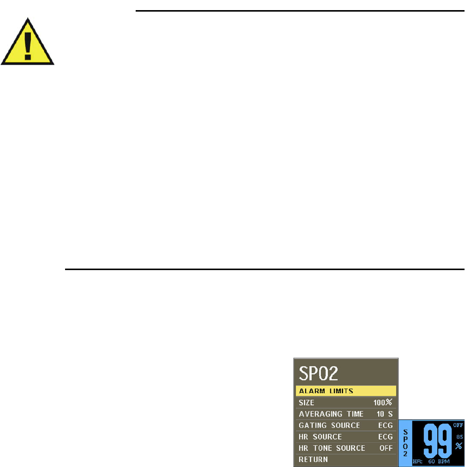
ExpressionMR200InstructionsforUseMonitoringSPO25‐9
Assessing Suspicious SPO2 Readings
Pulseoximetrymeasurementsarestatisticallydistributed.Withneweralgorithms,suchasFAST‐
SPO2,thecalculationofSPO2isnotdirectlylinkedtothecorrectdetectionofeachpulse.When
thepulserateisveryloworastrongarrhythmiaispresent,theSPO2/plethysmographypulse
ratemaydifferfromtheheartratecalculatedfromECG.Thisdoesnotindicateaninaccurate
SPO2value.IfyoudoubtthemeasuredSPO2,usetheplethysmographywavetoassessthesignal
quality.
WARNINGS
•Always shield (for example, cover with opaque material) the SPO2 clip or grip from
extraneous incidental light sources, as such light can cause erroneous SPO2 readings
or pulse detection errors.
• SPO2 monitoring requires the detection of valid pulses to correctly determine SPO2
and heart rate values. Any of the following items can lead to inaccuracies of the SPO2
readings and/or prolonged measurement time: Ambient light (including photodynamic
therapy), physical movement (patient and imposed motion), arrhythmias and/or
erratic heartbeats, diagnostic testing, electromagnetic interference, electrosurgical
units, dysfunctional hemoglobin, intravascular dyes, presence of dyes or pigments at
the application site, and inappropriate positioning of the pulse oximeter attachment. If
questionable readings are obtained, check the patient’s vital signs by alternate means
before administering medication.
•Attachment movement, ambient light (especially strobe or flashing lights) or
electromagnetic interference can give unexpected intermittent readings when the
sensor is not attached to a patient. Bandage and grip attachment designs are
particularly sensitive to minimal movement that might occur when the sensor is
dangling, not attached to the patient. An unapplied sensor may cause readings to be
displayed on the monitor. To avoid misdiagnosis, ensure the sensor is applied to
patient correctly.
SPO2 Menu
TheSPO2menuallowsyoutocontrolSPO2functions
andsettings.
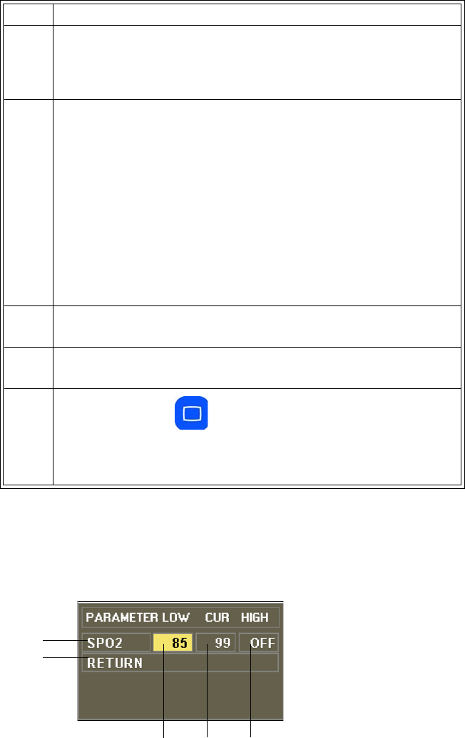
5‐10MonitoringSPO2ExpressionMR200InstructionsforUse
TochangesettingsintheSPO2menu
ALARM LIMITS
ControlstheSPO2alarmlimitsettings.(Seethetableonpage9‐15foralisting.)
Step Action
1TurnthecontrolknobtohighlighttheSPO2VSboxandthenpress
theknob.
TheSPO2menuappears.Currentsettingsaredisplayed.
2TurnthecontrolknobtoselectanyofthefollowingSPO2options
andthenpresstheknob:
ALARMLIMITS
SIZE
AVERAGINGTIME
GATINGSOURCE
HRSOURCE
HRTONESOURCE
Forinformationabouttheseoptions,seetheappropriatesections
below.
3Turntheknobtothedesiredsettingandthenpresstheknob.
4Tochangeothersettings,repeatsteps2and3.
5PresstheMainkeytoclosethemenu.
Alternative:TurntheknobtoRETURNandthenpresstheknob,or
waitapproximately60seconds.
12
3
4
5

ExpressionMR200InstructionsforUseMonitoringSPO25‐11
TosetthealarmlimitsforSPO2
SeeChangingtheSPO2AlarmLimitsonpage5‐8.
SIZE
ChangestheverticalscaleoftheSPO2(pleth)waveformsothathighamplitudescanbescaled
downtoavoidclippingofthepeaksandlowamplitudescanbescaleduptoviewthepeaks.
Thefollowingchoicesareavailable:
•10%
•20%
•40%
•60%
•80%
•100%(Default)
ToadjustthesizeoftheSPO2waveform
SeeChangingtheSPO2WaveformAmplitudeonpage5‐8.
AVERAGING TIME
Selectshowquicklythereadingrespondstochangesinthepatient’ssaturation,whereselecting
alongerdurationwillpreventthesaturationvaluefromchangingquicklywhichcanbeusefulfor
avoidingalarmtriggeringinpatientswithverydynamicconditionssuchasneonataland
pediatrics.
Thefollowingchoices(inseconds)areavailable:
•5S
•10S(Default)
•15S
Definition
1 Is the setting of the high alarm limit
2 Is the current measurement
3 Is the setting of the low alarm limit
4 Saves the settings and returns to the normal mode
5 Identifies SPO2 alarm limits

5‐12MonitoringSPO2ExpressionMR200InstructionsforUse
TosettheaveragingtimeoftheSPO2reading
EntertheSPO2menu.TurnthecontrolknobtoAVERAGINGTIMEandpresstheknob.Scrollto
thedesiredtimeandpresstheknob.
GATING SOURCE
Setsthecardiacgatingsourcebasedonameasuredsignal.(ThisisthesameoptionasintheECG
menu.)
Thefollowingchoicesareavailable:
•ECGisanoutputthatrepresentsthedetectionoftheR‐peakofaQRScomplex,asignalthe
MRsystemcanusedirectlyfortriggering.(Default)
•Pulseisasignalthatrepresentsthedetectionofthepeakoftheperipheralpulsecomplex.
Tosetthegatingsource
SeeUsingtheGatingFeatureonpage4‐26.
HR SOURCE
Selectsthesourcethatproducestheheartrate,asdisplayedintheECGandSPO2VSboxes
(identicaltoandinteractivewiththesameoptionintheECGmenu).
Thefollowingchoicesareavailable:
•AUTOselectsthesourceautomaticallyfromthehighestpriorityactiveinput,wherethe
MR200searchesforanothersourceonlywhenLEADFAILoccursorwhenECGisoff.Ifthe
highestpriorityinputisnotfound,thenextrankedparameterissought.Thepriority
rankingisECGandthenSPO2.Ifnoparameterspresentaheartrate,thenNONEis
displayedintheheartrateposition.
•ECGselectsECG.(Default)
•SPO2selectsSPO2.
Tosettheheartratesource
Step Action
1TurnthecontrolknobtohighlighttheSPO2VSbox(seepage5‐7)
andthenpresstheknob.
TheSPO2menuappears.Currentsettingsaredisplayed.
2TurnthecontrolknobtoHRSOURCEandthenpresstheknob.
TheHRSOURCEmenuappears.

ExpressionMR200InstructionsforUseMonitoringSPO25‐13
HR TONE SOURCE
Setsthesourceusedfortheheartratetone(identicaltoandinteractivewithsameoptioninthe
MONITOR>SOUNDADJUSTmenuandintheECGmenu).
Thefollowingchoicesareavailable:
•OFFremovestheheartsymbolfromthedisplayandnopulsetonewillbesounded.
(Default)
•QRSprovidesatonemodulatedbytheQRSdetectionfromtheECGvitalsign.
•SPO2providesatonemodulatedbytheSPO2vitalsign,wherethelowertheSPO2value,
thelowerthepitch.
Tosettheheartratetonesource
EntertheSPO2menu.TurnthecontrolknobtoHRTONESOURCEandpresstheknob.Scrollto
thedesiredsettingandpresstheknob.(Seepage3‐8fordetailedinstructions.)
3Turnthecontrolknobtoselectoneofthefollowingoptionsand
thenpresstheknob:
AUTO
ECG
SPO2
Thesettingischanged.
Step Action
5‐14MonitoringSPO2ExpressionMR200InstructionsforUse

ExpressionMR200InstructionsforUseMonitoringNiBP6‐1
CHAPTER 6
Monitoring NiBP
TheNiBP(non‐invasivebloodpressure)parametermeasuresanddisplayssystolic,diastolicand
meanarterialpressures.Alarmlimitsettingsareavailableforallthreepressures.Whenusing
NiBPtomeasurebloodpressure,readingsarenotcontinuousbutareupdatedeachtimeablood
pressuremeasurementistaken.Setashorterintervalwhenfrequentupdatingofthepatient’s
bloodpressureisneeded.Visuallycheckingthepatient,confirmingNiBPmeasurementsagainst
othervitalsignmeasurementsandattentiontothelimbwherethecuffisattachedmustbe
standardroutinesduringNiBPuse.
Adultandpediatricbloodpressuremeasurementsdeterminedwiththisdeviceareequivalentto
thoseobtainedbyatrainedobserverusingthecuff/stethoscopeauscultatorymethod,withinthe
limitsprescribedbytheAmericanNationalStandard,Manual,electronic,orautomated
sphygmomanometers.
Neonatalbloodpressuremeasurementsdeterminedwiththisdeviceareequivalenttothose
obtainedbyanintra‐arterialbloodpressuremeasurementdevice,withinthelimitsprescribedby
theAmericanNationalStandard,Manual,electronic,orautomatedsphygmomanometers.
WARNINGS
•Use clinical judgment to decide whether to perform a repeated series of NiBP
measurements because of the risk of purpura, ischemia and neuropathy in the limb
with the NiBP cuff.
• Arrhythmias, erratic heartbeats and patient motion can result in inaccurate readings
and/or prolonged measurements. If questionable readings are obtained, check the
patient’s vital signs by alternate means before administering medication.
• The performance of the automated sphygmomanometer can be affected by extremes of
temperature, humidity and altitude.
• An alarm will sound when the MR200 is too close to the MR magnet and shutdown of
NiBP monitoring will occur. Always position the MR200 as indicated on page 2-6.
CAUTIONS
• Substitution of components or accessories different from those supplied or recommended
can result in measurement errors.
• NiBP accuracy has not been verified in the presence of some common arrhythmias such as
atrial or ventricular premature beats or atrial fibrillation.

6‐2MonitoringNiBPExpressionMR200InstructionsforUse
Patient Preparation for NiBP Monitoring
WARNING
The NiBP cuff inflation rate may increase and the initial pressure may increase up to 180
mmHg when changing the patient type.
ThePATIENTtypesettingdeterminestheinflationpressuresoftheNiBPcuffandthereading
times.
Insomecases,apatientmayexhibitalowpulseamplitudeduetoanyofthefollowing
conditions.Thelistprovidesonlysomeexamplesofpotentialcausesoflowpulseamplitudesthat
canmakeNiBPdifficulttomeasureinaconvenientandtimelymanner:
• Medication
•Sedation
•Diseaseorillness
• Physiologicalorneurologicalconditions
•Obesity(oranyoccurrenceofmetabolismwithextremevariations)
• Stress
•Size
CAUTION
There may be occasions when a particular mode is not suitable for its apparent category of patients
based on age alone. In these cases, a clinical decision shall be made to use another patient type,
NiBP cuff size or measurement technique. The clinical decision shall be based on all of the factors
listed in Determining the Patient Type (see page 3-10) to ensure the best possible and most timely
NiBP measurement acquisition.
NOTE
ADULT and PEDIATRIC types dictate use of a larger NiBP cuff and interconnect hose size,
while NEO uses smaller sizes; see the cuff and hose information on page 1-27.
AwidevarietyofNiBPcuffsandinterconnecthosesareavailableforyourmonitoringneeds;see
page1‐27fordetails.
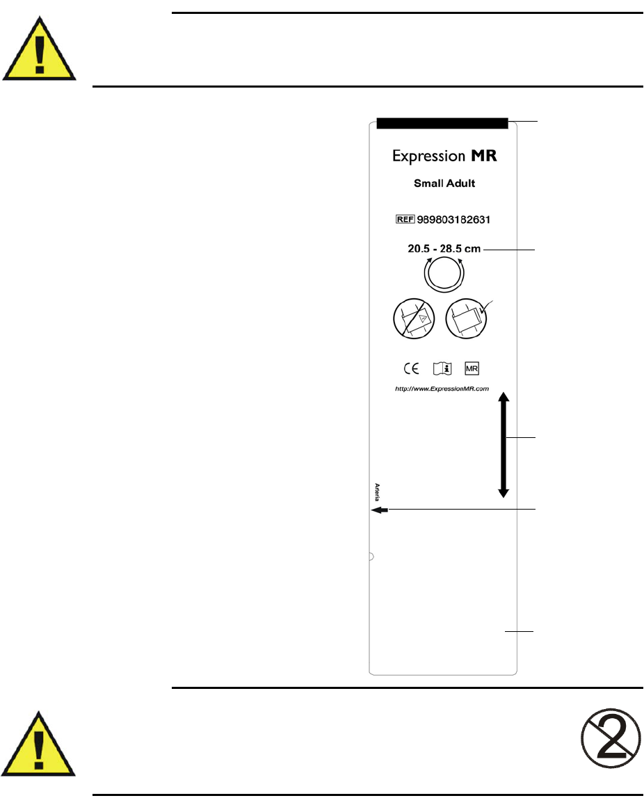
ExpressionMR200InstructionsforUseMonitoringNiBP6‐3
Selecting the NiBP Cuff
WARNING
To ensure accurate reliable measurements, use only the recommended NiBP accessories. Use
the appropriate NiBP cuff size for each patient, as recommended by the current American
Heart Association guidelines for blood pressure monitoring, to ensure safety and accuracy.
TheNiBPcuffshouldbeselectedand
positionedasitwouldbeforanauscultatory
bloodpressuredetermination.Thecurrent
guidelinesoftheAmericanHeartAssociation
mustbefollowed.
Thebladderwidthofthecuffmustbe40
percentofthecircumferenceofthelimb.Itis
alsoadvisabletokeeptheairvolumetoa
minimumbyusingthesmallestcuffsize
possibleforeachpatient.Thepointof
maximumoscillationsiscoincidentwithmean
arterialpressureregardlessofarterialelasticity
solongastheratioofairvolumeinthecuffto
thevolumeofthearteryundercompression
doesnotgreatlyexceedten(10)toone(1).
ForacorrectNiBPcufffit:
•Adultandpediatricpatients—theindex
lineonthesizechosenshouldfallwithin
therangelinewhenplacedonthe
patient.
• Neonatalpatients—thesizechosen
shouldbewithinthestated
circumferencerangeforthelimbofthe
neonate.
•Allpatients—alignthecufftoensurethe
arterymarkisplacedovertheartery.
WARNING
Single use devices, as indicated on the device packaging, should be disposed of
after use and must never be reused. Follow your hospital’s guidelines for
appropriate disposal. Reuse of single-use devices can result in spread of patient
infection, degradation of monitoring performance, or inaccurate
measurements.
Index line
Range line
Circumference
range
Artery mark
NiBP cuff
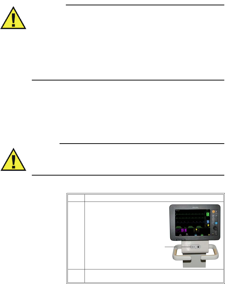
6‐4MonitoringNiBPExpressionMR200InstructionsforUse
Positioning the NiBPCuff
WARNINGS
•Avoid compression, kinking or restriction of the NiBP cuff hose, as the effect of blood
flow interference can result in patient injury caused by continuous cuff pressure.
• Do not use the NiBP cuff on a limb with an intravenous infusion or where an arterial
catheter or arterio-venous (A-V) shunt is in place because of temporary interference to
blood flow. This could result in injury to the patient.
• Do not place the NiBP cuff over a wound, as this can cause further injury.
• Do not place the NiBP cuff on the same or adjacent arm to a mastectomy, or where the
lymph nodes were removed, or if a shunt is on that arm. This can lead to bruising,
inaccurate readings, or negatively impact the drainage of fluids because of temporary
interference to blood flow.
WraptheNiBPcufffirmly(notsnuggly)aroundthearmorlegofthepatient,makingsurethat
thecuffisattheapproximatelevelofthehearttoensureaccuracyoftheobtainedvalues.
Connecting the NiBP Cuff
WARNING
Routinely inspect the NiBPcuff and hose assemblies for proper connection and orientation.
Replace accessories that have cracks, holes, tears, or cuts that could cause leaks in the
system. If such damaged NiBP cuff or hose assemblies are used, prolonged and/or inaccurate
patient readings could result.
ToconnecttheNiBPcuffandhose
Step Action
1Insertthe
appropriate
interconnecthose
connectorontothe
NiBPport.Pushthe
hoseconnector
forwardandthen
turnitclockwise.
2AttachaNiBPcuffappropriateforthepatienttypeandsizetothe
interconnecthose.
NiBP port
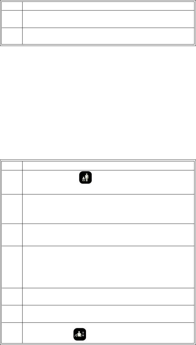
ExpressionMR200InstructionsforUseMonitoringNiBP6‐5
Choosing the Measurement Mode
NiBPmeasurementscanbetakenusingamode(autoormanual)thatbestsuitstheneedsof
yourpatient.
Selecting Auto Mode
Youcanautomaticallymeasureapatient’sbloodpressureatpre‐definedintervals,whichare
measuredfromthestartofoneNiBPmeasurementtothestartofthenext.
Toturnonautomaticoperation
3 Positionthecuffonthepatient;seepage6‐4.
4Ensurethatthecuffandinterconnecthosesarenotkinked.
Step Action
Step Action
1PressthePatientkeyandthenselecttheappropriate
PATIENTtype;seepage3‐10fordetails.
2TurnthecontrolknobtohighlighttheNiBPVSbox(seepage6‐11)
andthenpresstheknob.
TheNiBPmenuappears.Currentsettingsaredisplayed.
3TurnthecontrolknobtoINTERVALandthenpresstheknob.
TheINTERVALmenuappears.Thecurrentsettingishighlighted.
4Turnthecontrolknobtoselectanyofthefollowingsettingsand
thenpresstheknob:
1,2,2.5,3,5,10,15,20,30and45minutes,and1,2and4hours.
Theselectionisentered.
5TurnthecontrolknobtoAUTOMODEandthenpresstheknob.
6TurnthecontrolknobtoONandthenpresstheknob.
7PresstheNiBPkeytobeginmeasurements.
6‐6MonitoringNiBPExpressionMR200InstructionsforUse
NOTE
If gauss shutdown occurs during an AUTO MODE measurement, NiBP readings will stop. When
at a safe distance, operation will resume—a reading will be taken and then the intervals will begin
again.
Making Manual Measurements
Youcanmanuallydefinethemeasurementintervalofapatient’sbloodpressure.
Tocontrolmanualoperation
Initial Inflation Pressures and Reading Durations
WARNINGS
• Too frequent NiBP measurements can cause injury to the patient due to blood flow
interference.
• Always monitor the NiBP cuff site (for example, by observation of the limb concerned)
to ensure that operation of the automated sphygmometer does not result in prolonged
impairment of the circulation of the blood of the patient.
• Pressurization of the NiBP cuff can can temporarily cause loss of function of
simultaneously used monitoring ME equipment on the same limb.
TheinitialinflationpressureistheamountthattheNiBPcuffwillinflateforthefirstNiBP
measurement:
•ADULTisusedformostadultpatients:Initialinflationpressure:165±15mmHg
•PEDIATRICisusedforanypatientexhibitinglowpulseamplitudes(aconditionexhibitedby
pediatric‐sizepatients):Initialinflationpressure:130±15mmHg
•NEOisusedformostneonatalpatients:Initialinflationpressure:100±15mmHg
WhensubsequentNiBPmeasurementsaretakenonthesamepatient(andifnotinsuspend
mode),themonitoradjuststheinflationvalueupordownbasedonthepreviousreadingresults.
Step Action
1PressthePatientkeyandthenselecttheappropriate
PATIENTtype;seepage3‐10fordetails.
2PresstheNiBPkeytostartandstopamanualNiBP
measurement.
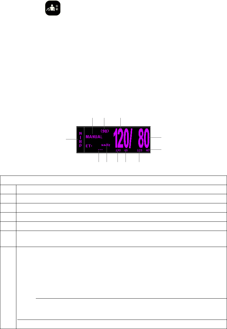
ExpressionMR200InstructionsforUseMonitoringNiBP6‐7
Stopping an NiBP Measurement
PresstheNiBPkeytostopareadingcycle.
NiBP VS Box
DependingupontheselectedFORMAT(seepage6‐14),theNiBPVSboxisdisplayedaccordingly.
Systolic/Diastolic Format
TheelementscontainedintheSYS/DIAformataredescribedbelow.
Definition
1 Is the NiBP diastolic pressure measurement (numeric)
2 Is the low limit of the NiBP diastolic alarm setting; see page 6-12
3 Is the high limit of the NiBP diastolic alarm setting; see page 6-12
4 Is the low limit of the NiBP systolic alarm setting; see page 6-12
5 Is the high limit of the NiBP systolic alarm setting; see page 6-12
6 Is the unit of measure for the NiBP pressure readings, where mmHg is millimeters of
mercury and kPa is kilopascals; see PRESSURE UNITS on page 11-16
7 Is the time since the last completed NiBP reading, displayed in the following format:
<hh>:<mm>:<ss>, where
<hh> = Two-digit hours field
<mm> = Two-digit minutes field
<ss> = Two-digit seconds field
NOTE
During a reading, this displays the cuff pressure.
1
2
435
6
7
8
910 11
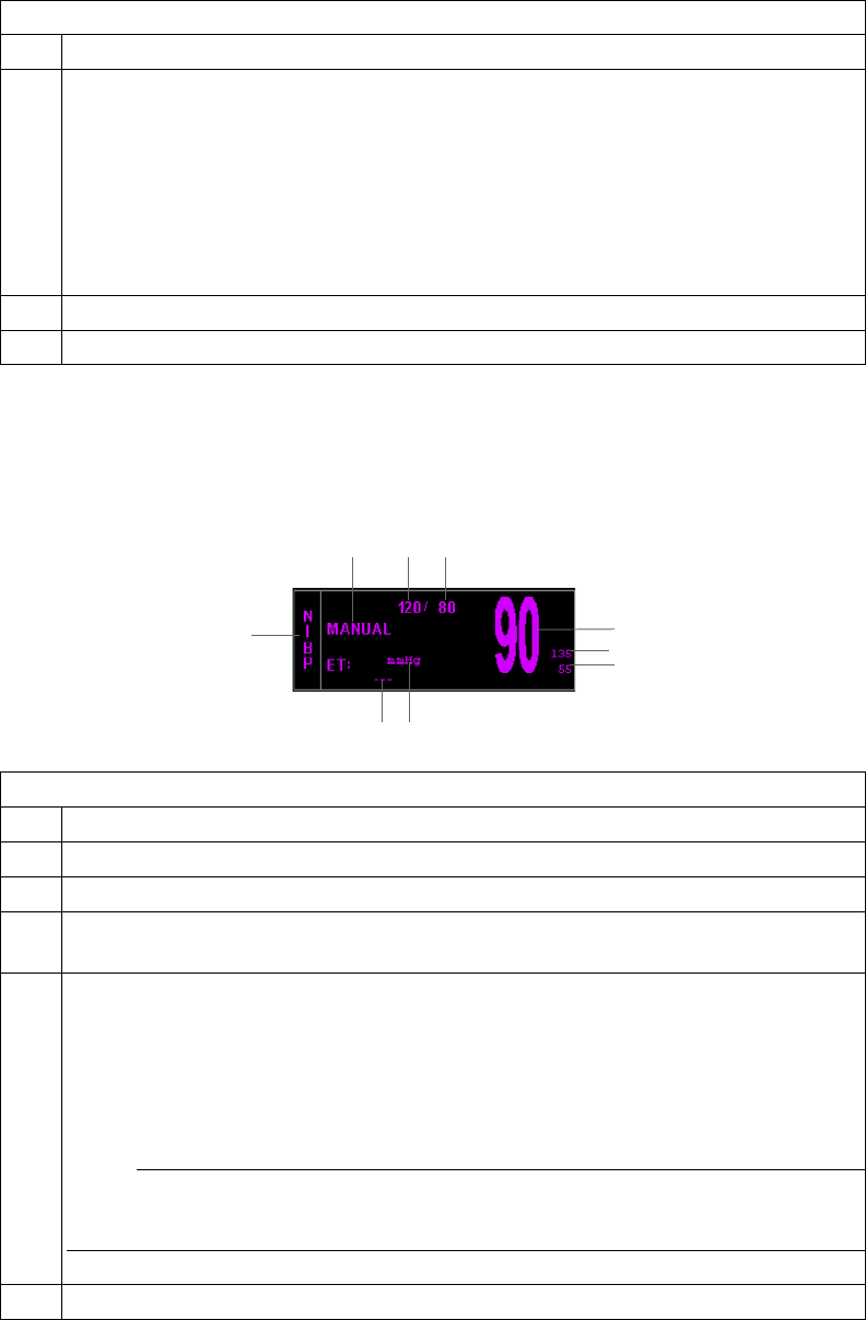
6‐8MonitoringNiBPExpressionMR200InstructionsforUse
Mean Format
TheelementscontainedintheMEANformataredescribedbelow.
8 Is the name of the vital sign
9 Is the mode: where MANUAL is displayed when in Manual mode, and NEXT when in
Auto mode. In Auto mode, indicates the time until the next NiBP measurement,
displayed in the following format:
<hh>:<mm>:<ss>, where
<hh> = Two-digit hours field
<mm> = Two-digit minutes field
<ss> = Two-digit seconds field
10 Is the NiBP mean pressure measurement (numeric)
11 Is the NiBP systolic pressure measurement (numeric)
Definition
Definition
1 Is the NiBP mean pressure measurement (numeric)
2 Is the high limit of the NiBP mean alarm setting; see page 6-12
3 Is the low limit of the NiBP mean alarm setting; see page 6-12
4 Is the unit of measure for the NiBP pressure readings, where mmHg is millimeters of
mercury and kPa is kilopascals; see PRESSURE UNITS on page 11-16
5 Is the time since the last completed NiBP reading, displayed in the following format:
<hh>:<mm>:<ss>, where
<hh> = Two-digit hours field
<mm> = Two-digit minutes field
<ss> = Two-digit seconds field
NOTE
During a reading, this displays the cuff pressure.
6 Is the name of the vital sign
1
2
3
54
6
789

ExpressionMR200InstructionsforUseMonitoringNiBP6‐9
Changing the NiBP Alarm Limits
TochangetheNiBPalarmlimitsettings
NOTE
To make global changes to the parameter alarm limit settings based upon the patient’s current
vital sign readings, see Setting Alarm Limits Globally on page 9-4.
7 Is the mode: where MANUAL is displayed when in Manual mode, and NEXT when in
Auto mode. In Auto mode, indicates the time until the next NiBP measurement,
displayed in the following format:
<hh>:<mm>:<ss>, where
<hh> = Two-digit hours field
<mm> = Two-digit minutes field
<ss> = Two-digit seconds field
8 Is the NiBP systolic pressure measurement (numeric)
9 Is the NiBP diastolic pressure measurement (numeric)
Definition
Step Action
1TurnthecontrolknobtohighlighttheNiBPVSbox(seepage6‐11)
andthenpresstheknob.
TheNiBPmenuappears.Currentsettingsaredisplayed.
2TurnthecontrolknobtoALARMLIMITSandthenpresstheknob.
TheALARMLIMITSmenuappears.Currentsettingsaredisplayed;
seepage6‐12fordetails.
3Turntheknobtothel
oworhigh
settingandthenpresstheknob.
Themeasurementandsettingareselected.
4Turntheknobtochangethesettingvalueandthenpresstheknob
tomakethechangeeffectiveandreturntothescrollingfunction.
Thesettingischanged.
5Tochangeotheralarmsettings,repeatsteps3and4.

6‐10MonitoringNiBPExpressionMR200InstructionsforUse
Changing the Unit of Measure
NOTE
When using the IP5 and PRESSURE UNITS is changed, the displayed formatting of the value
and placement of the decimal point is changed immediately. However, it can take up to 2 seconds
for the numeric values to reflect the new unit of measure. Do not print or perform data captures
during this period.
Tochangetheunitofmeasure
Step Action
1PresstheSETUPkey.
TheSETUPmenuappears.
2TurnthecontrolknobtoMONITORSETUPandthenpresstheknob.
TheMONITORmenuappears.Currentsettingsaredisplayed.
3TurnthecontrolknobtoSERVICE(BIO‐MED)andpresstheknob.
TheSERVICE(BIO‐MED)menuappears.
4TurnthecontrolknobtoSYSTEMCONFIGandpresstheknob.
TheSYSTEMCONFIGsubmenuappears.Currentsettingsare
displayed.
5TurnthecontrolknobtoPRESSUREUNITSandthenpresstheknob.
ThePRESSUREUNITSmenuappears.Thecurrentsettingis
highlighted.
6Turntheknobtothedesiredsettingandthenpresstheknob.
mmHg
kPa
Thesettingisselected.
7PresstheMainkeytoclosethemenu.
Alternative:TurntheknobtoRETURNandthenpresstheknob.
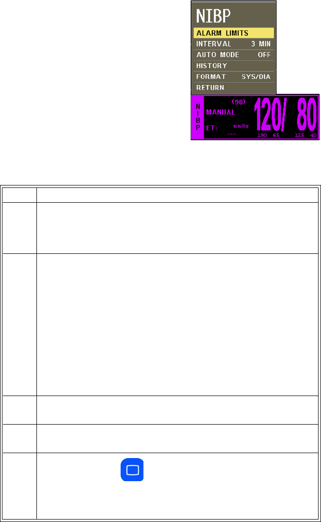
ExpressionMR200InstructionsforUseMonitoringNiBP6‐11
NiBP Menu
TheNiBPmenuallowsyoutocontrolnon‐invasiveblood
pressurefunctionsandsettings.
TochangesettingsintheNiBPmenu
Step Action
1TurnthecontrolknobtohighlighttheNiBPVSboxandthenpress
theknob.
TheNiBPmenuappears.Currentsettingsaredisplayed.
2TurnthecontrolknobtoselectanyofthefollowingNiBPoptions
andthenpresstheknob:
ALARMLIMITS
INTERVAL
AUTOMODE
HRSOURCE
HISTORY
FORMAT
Forinformationabouttheseoptions,seetheappropriatesections
below.
3Turntheknobtothedesiredsettingandthenpresstheknob.
4Tochangeothersettings,repeatsteps2and3.
5PresstheMainkeytoclosethemenu.
Alternative:TurntheknobtoRETURNandthenpresstheknob,or
waitapproximately60seconds.
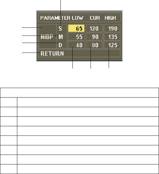
6‐12MonitoringNiBPExpressionMR200InstructionsforUse
ALARM LIMITS
ControlsthealarmlimitsettingsforNiBP.(Seethetableonpage9‐15foralisting.)
TosetthealarmlimitsforNiBP
SeeChangingtheNiBPAlarmLimitsonpage6‐9.
INTERVAL
Setstheintervalforautomaticmeasurements.
Thefollowingchoicesareavailable:
•1Minute
•2Minutes
•2.5Minutes
•3Minutes(Default)
•5Minutes
•10Minutes
Definition
1 Are the settings of the high alarm limits
2 Are the current measurements
3 Are the settings of the low alarm limits
4 Saves the settings and returns to the normal mode
5 Identifies diastolic alarm limits
6 Identifies mean alarm limits
7 Identifies NiBP alarm limits
8 Identifies systolic alarm limits
12
3
4
5
6
7
8

ExpressionMR200InstructionsforUseMonitoringNiBP6‐13
•15Minutes
•20Minutes
•30Minutes
•45Minutes
•1Hour
•2Hours
•4Hours
TosettheintervalforNiBPreadings
EntertheNiBPmenu.TurnthecontrolknobtoINTERVALandpresstheknob.Scrolltothe
desiredtimeandpresstheknob.
AUTO MODE
SetsthemodeusedtotakeNiBPreadings.
NOTE
A manual reading will not restart this cycle time.
Thefollowingchoicesareavailable:
•ONtakesreadingsautomatically.Whenswitchedfromofftoon,thefirstreadingmustbe
initiatedbypressingtheNiBPkey.Allsubsequentreadingswillbetakenautomaticallyat
theselectedinterval.
•OFFtakesreadingsmanually(Manualmode),wherereadingsareinitiatedbypressingthe
NiBPkey.(Default)
TosetthemodeforNiBPreadings
EntertheNiBPmenu.TurnthecontrolknobtoAUTOMODEandpresstheknob.Scrolltothe
desiredmethodandpresstheknob.
HISTORY
Displaysthelast48NiBPreadingswiththetime,heartrate,SPO2,CO2andrespirationvaluesina
tabularform(6perpage).Thisdataisretainedinnon‐volatilememory,protectedagainstpower
loss.
ToviewpreviousNiBPreadings
EntertheNiBPmenu.TurnthecontrolknobtoHISTORYandpresstheknob.

6‐14MonitoringNiBPExpressionMR200InstructionsforUse
FORMAT
Changestheformatofthedisplayedpressurenumerics.
Thefollowingchoicesareavailable:
•SYS/DIAdisplaystheNiBPreadingsinthesystolic/diastolicformat;seepage6‐7.(Default)
•MEANdisplaystheNiBPreadingsinthemeanformat;seepage6‐8.
Tochangetheformat
Step Action
1TurnthecontrolknobtohighlighttheNiBPVSbox(seepage6‐11)
andthenpresstheknob.
TheNiBPmenuappears.Currentsettingsaredisplayed.
2TurnthecontrolknobtoFORMATandthenpresstheknob.
TheFORMATmenuappears.Thecurrentsettingishighlighted.
3Turnthecontrolknobtoselectfromthefollowingsettingsandthen
presstheknob:
SYS/DIA
MEAN
Theselectionisentered.

ExpressionMR200InstructionsforUseMonitoringCO27‐1
CHAPTER 7
Monitoring CO2
WhenequippedwiththeCO2option,theMR200samplesandanalyzesthepatient’sairway
respiratorygasusingsidestreammeasurementtoproduce:
•Aninspired(FiCO2)valuederivedduringinspirationandanendtidal(EtCO2)value
measuredduringexpiration.
•Arespirationrate(RESP):Thenumberofbreathsperminute;seechapter8fordetails.
•Awaveformoftheconcentrationofcarbondioxideintherespiratorygases.
NOTE
Inspired CO2 (FiCO2) is the lowest reading of the CO2 waveform in the previous 20 seconds.
WARNINGS
•Do not use on patients that cannot tolerate the withdrawal of 50ml/min ± 10 ml/min
from the airway or patients that cannot tolerate the added dead space to the airway.
• An alarm will sound when the MR200 is too close to the MR magnet and shutdown of
CO2 monitoring will occur. Always position the MR200 as indicated on page 2-6.
Patient Preparation for CO2 Monitoring
Whenpreparingapatient,theaccessorypositiononthepatientwillimpacttheperformanceand
operationoftheCO2parameter.
Selecting the CO2 Accessory
Inpatientsonabreathingcircuit,asampleoftherespiratorygasisdrawnfromthepatient’s
breathingcircuitthroughanairwayadapterandagassamplingline.Inpatientswhoarenotona
breathingcircuit,thegassampleisdrawnthroughanasalcannula.Thesespeciallydesigned
cannulasandon‐airwayadaptersincorporateafilterandsamplecelltoprovidemaximum
filtrationoffluidsandcontaminantstoprotectagainstsystemintake.WhenselectingCO2
accessories(seepage1‐25),considerthefollowing:
•Thetypeofpatient(adult,pediatric,orneonatal)
•Whetherthepatientisreceivingsupplementaloxygen
•Theconditionofthepatient
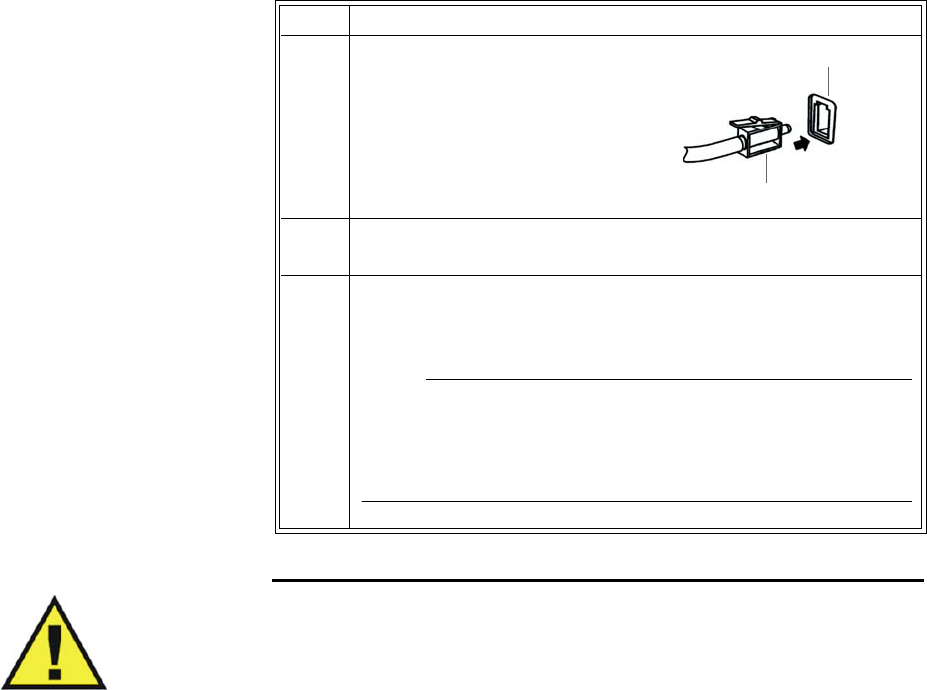
7‐2MonitoringCO2ExpressionMR200InstructionsforUse
•Allaccessoriesaresingleuse.
Connecting the Sampling Line
Toconnectthesamplingline
WARNINGS
•Inspect CO2 port and accessories before use. If the sampling line, connector or port
show signs of damage, replace the part immediately or discontinue use and contact
technical support. Never use damaged equipment.
• Frequently inspect the patient sampling line and keep it clear of any moving
mechanisms (for example, table wheels) which could cut, pinch, or dislodge the
sampling line. Leaks, reduced or stopped flow, or internal venting of sampled gas into
damaged tubing will cause inaccurate measurements.
• Do not position the sampling line in any manner that may cause entanglement or
strangulation.
• Replace the sampling line if excessive secretions are observed, as inaccurate
measurements could result if the flow is reduced or stopped.
• Leakages in the breathing system or sampling system may cause the displayed EtCO2
values to be too low. Always connect all components securely and check for leaks
according to standard clinical procedures. Displacement of the sampling line cannula
or airway adapter can cause lower than actual EtCO2 readings.
Step Action
1Insertthesamplinglineconnector
intotheCO2portandthenpushthe
connectorforwarduntilyoufeelor
hearitclickintoplace.
2IfCO2WARMINGUPisdisplayed,waitasthesystemthermally
stabilizes.Whenthemessageiscleared,CO2isfullyoperational.
3AlwaysremovethepatientsamplinglinefromtheCO2portwhen
notinuse.(Toremovethesamplingline,pressdownonthelocking
tabandpulltheconnectorfromtheport.)
NOTE
To increase the life of the filter and pump, when CO2 will not be
used to monitor a patient, it is recommended to turn off CO2 in the
PARAMETER SELECTION menu; see page 3-7.
Sampling line connector
CO2 port
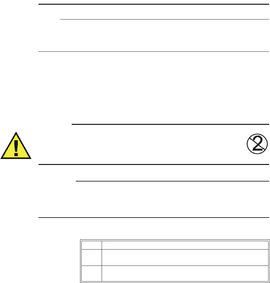
ExpressionMR200InstructionsforUseMonitoringCO27‐3
• If CO2 values for patients who are not on a breathing circuit appear extremely low,
check whether the patient is breathing through the mouth or whether one nostril is
blocked.
NOTES
• For optimum fit and compatibility, use only specified parts.
• Always inspect patient sampling line after attachment to the MR200.
Applying the Sampling Line to the Patient
Selectthepatientsamplinglinethatisappropriateforthepatientsizeandapplication.Patient
samplinglineswiththeairwayadapterareintendedforusewithbreathingcircuitsand
anesthesiacircuitsthathaveanintegratedairwayadapter.
WARNING
Patient sampling lines are intended for single-patient use only. Do not clean or
disinfect these items. Follow your hospital’s guidelines for appropriate disposal.
Reuse of single-use devices can result in spread of patient infection, degradation
of monitoring performance, or inaccurate measurements.
CAUTIONS
• The accuracy of the data is greatly influenced by the proper use and fitting of the patient
sampling line to ensure proper sampling without the introduction of outside air.
• Remove the patient sampling line from the CO2 port when not in use.
Toplacethesamplinglineonthepatient
Step Action
1Ensurethatthesamplinglineisclean,dryandundamaged.Replace
thelineifnecessary.
2InsertthesamplinglineconnectorintotheCO2port(seepage7‐2).
Aclickwillbeheardwhenproperlyinserted.
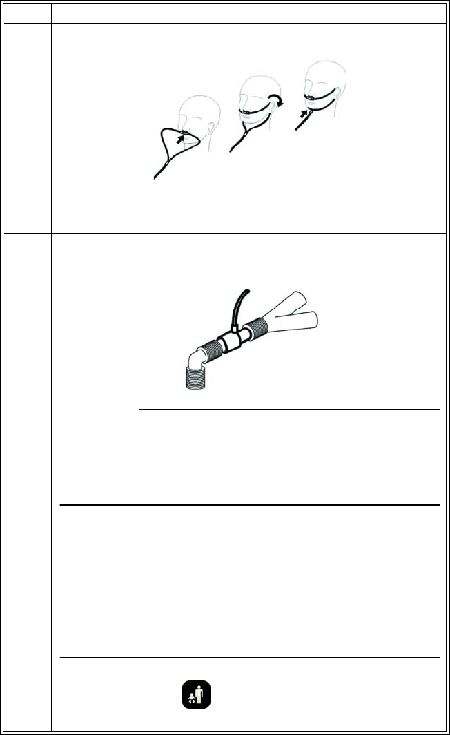
7‐4MonitoringCO2ExpressionMR200InstructionsforUse
3Placethesamplinglineontothepatient,asshownbelow.
4Ifusingthesamplinglinewiththeairwayadapter,proceedtostep
5;otherwisegotostep7.
5Placetheairwayadapterattheproximalendoftheairwaycircuit
betweentheelbowandthebreathingcircuitwye,asshownbelow.
CAUTION
Always insert the patient sampling line into the CO2 port before
inserting the airway adapter into the breathing circuit. Failure to
follow this may introduce a leak in the circuit, thereby reducing set
minute volume.
NOTE
Do not place the airway adapter between the ET tube and the elbow
as this may allow patient secretions to accumulate in the adapter. If
pooling does occur, replace the airway adapter. To prevent moisture
from draining into the airway adapter, always place the adapter
tubing in a up position, as shown above.
6PressthePatientkeyandthenselecttheappropriate
PATIENTtype;seepage3‐10fordetails.
Step Action
ExpressionMR200InstructionsforUseMonitoringCO27‐5
7Checkthattheconnectionshavebeenmadecorrectlybyverifying
thepatient’sbreathingeffortswiththedisplayedwaveform.
WARNING
Before completion of patient setup, ensure that the
patient’s breathing efforts coincide with the displayed
CO2 waveform.
8Ifthefollowingwarningisdisplayed:
PersistentCO2occlusiondetected.
PleaseclearocclusionandpressOK
toresumeusingCO2
Clearanypinchesorobstructionsinthesamplinglinebefore
proceeding.
Step Action
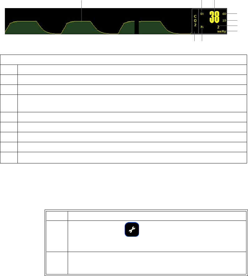
7‐6MonitoringCO2ExpressionMR200InstructionsforUse
CO2 Waveform and VS Box
TheelementscontainedintheCO2waveform(TraceD)andVSboxaredescribedbelow.
Changing the Waveform Speed
TochangetheCO2waveformspeed
Definition
1 Is the high limit setting of the CO2 alarm; see page 7-9
2 Is the low limit setting of the CO2 alarm; see page 7-9
3 Is the inspired FiCO2 (inspired CO2) measurement (numeric)
4 Is the unit of measure for the CO2 numeric data, where mmHg is millimeters of
mercury and kPa is kilopascals; see page 7-11
5 Is the label for the FiCO2 measurement
6 Is the name of the vital sign
7 Is the detected CO2 waveform
8 Is the label for the EtCO2 measurement
9Is the EtCO2 (expired CO2) measurement (numeric)
1
2
3
5
6
79
8
4
Step Action
1PresstheSETUPkey.
TheSETUPmenuappears.
2TurnthecontrolknobtoMONITORSETUPandthenpresstheknob.
TheMONITORmenuappears.Currentsettingsaredisplayed.

ExpressionMR200InstructionsforUseMonitoringCO27‐7
Changing the CO2 Alarm Limits
TochangetheEnd‐tidalCO2alarmlimitsettings
NOTES
• To make global changes to the parameter alarm limit settings based upon the patient’s
current vital sign readings, see Setting Alarm Limits Globally on page 9-4.
• The high alarm limit for inspired CO2 is fixed.
3TurntheknobtoRESPSPEEDandthenpresstheknob.
TheRESPSPEEDmenuappears.Thecurrentsettingishighlighted.
4Turnthecontrolknobtoselectanyofthefollowingsettings(see
page3‐14fordetails)andthenpresstheknob:
25mm/s
12.5mm/s
6.25mm/s
3.125mm/s
1.5625mm/s
0.33333mm/s
Theselectionisentered.
Step Action
Step Action
1TurnthecontrolknobtohighlighttheCO2VSbox(seepage7‐8)
andthenpresstheknob.
TheCO2menuappears.Currentsettingsaredisplayed.
2TurnthecontrolknobtoALARMLIMITSandthenpresstheknob.
TheALARMLIMITSmenuappears.Currentsettingsaredisplayed;
seepage7‐9fordetails.
3Turntheknobtothel
oworhigh
settingandthenpresstheknob.
Thesettingisselected.
4Turntheknobtochangethesettingvalueandthenpresstheknob
tomakethechangeeffectiveandreturntothescrollingfunction.
Thesettingischanged.
5Tochangetheremainingsetting,repeatsteps3and4.
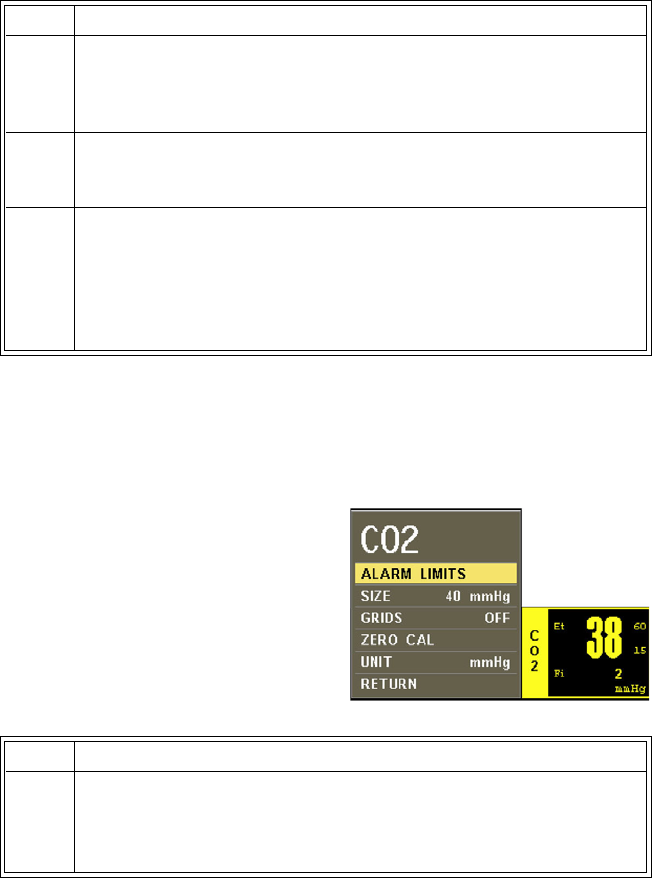
7‐8MonitoringCO2ExpressionMR200InstructionsforUse
Changing the Unit of Measure
Tochangetheunitofmeasure
CO2 Menu
TheCO2menuallowsyoutocontrolCO2andCO2‐derived
respirationfunctionsandsettings.
TochangesettingsintheCO2menu
Step Action
1TurnthecontrolknobtohighlighttheCO2VSbox(seebelow)and
thenpresstheknob.
TheCO2menuappears.Currentsettingsaredisplayed.
2TurnthecontrolknobtoUNITandthenpresstheknob.
TheUNITmenuappears.Thecurrentsettingishighlighted.
3TurntheknobtoselectoneofthefollowingCO2settings:
mmHg
kPa
Thesettingisselected.
Step Action
1TurnthecontrolknobtohighlighttheCO2VSboxandthenpress
theknob.
TheCO2menuappears.Currentsettingsaredisplayed.
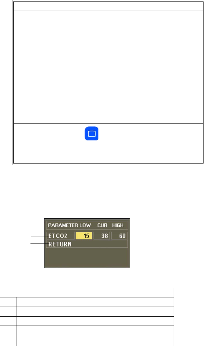
ExpressionMR200InstructionsforUseMonitoringCO27‐9
ALARM LIMITS
ControlsthealarmlimitsettingsforCO2.(WhenSOURCEissettoBELintheRESPmenu,theCO2
respirationalarmlimitsettingswillalsobedisplayed;seepage8‐5.)
2TurnthecontrolknobtoselectanyofthefollowingCO2options
andthenpresstheknob:
ALARMLIMITS
SIZE
GRIDS
ZEROCAL
UNIT
Forinformationabouttheseoptions,seetheappropriatesections
below.
3Turntheknobtothedesiredsettingandthenpresstheknob.
4Tochangeothersettings,repeatsteps2and3.
5PresstheMainkeytoclosethemenu.
Alternative:TurntheknobtoRETURNandthenpresstheknob,or
waitapproximately60seconds.
Definition
1 Is the setting of the high alarm limit
2 Is the current measurement
3 Is the setting of the low alarm limit
4 Saves the settings and returns to the normal mode
5Identifies expired CO2 alarm limits
Step Action
12
3
4
5
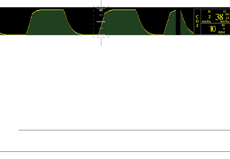
7‐10MonitoringCO2ExpressionMR200InstructionsforUse
TosetthealarmlimitsforCO2
SeeChangingtheCO2AlarmLimitsonpage7‐7.
SIZE
SetstheCO2waveformsize.
Thefollowingchoicesareavailable:
•40mmHg(Default)
•60mmHg
•80mmHg
ToadjustthegridsizefortheCO2waveform
EntertheCO2menu.TurnthecontrolknobtoSIZEandpresstheknob.Scrolltothedesiredsize
andpresstheknob.
GRIDS
ControlstheCO2griddisplay.
Thefollowingchoicesareavailable:
•ON
•OFF(Default)
TocontrolCO2griddisplay
EntertheCO2menu.TurnthecontrolknobtoGRIDSandpresstheknob.Scrolltothedesired
settingandpresstheknob.
NOTE
Grids will not be displayed during a CO2 ACCURACY CHECK; see page 11-14.
Grid
Size

ExpressionMR200InstructionsforUseMonitoringCO27‐11
ZERO CAL
Initiatesazerocalibration(anautomaticfunctionduringnormaluse)oftheCO2systemtoallow
forthedifferentcharacteristicsofeachaccessorytype.Themaximumtimerequiredforis
approximately40seconds.
Undercertainconditions,ZEROCALwillnotbeallowed:
•Iflessthan20secondshavepassedsincedetectionofthelastbreath;
•IftheCO2temperatureisunstable;or
•WhenthesamplinglineisdisconnectedfromtheCO2port.
NOTE
ZERO CAL is not required when switching sampling lines.
Toperformazerocalibration
UNIT
SelectstheunitofmeasureusedforpresentationoftheCO2numericdata.
Thefollowingchoicesareavailable:
•mmHg(Default)
•kPa
ToselecttheunitofmeasureforCO2
EntertheCO2menu.TurnthecontrolknobtoUNITandpresstheknob.Scrolltothedesired
settingandpresstheknob.
Step Action
1EnsurethatCO2WARMINGUPisnotdisplayed.
2TurnthecontrolknobtohighlighttheCO2VSboxandthenpress
theknob.
TheCO2menuappears.Currentsettingsaredisplayed.
3TurnthecontrolknobtoselectZEROCALandthenpresstheknob.
PERFORMINGCO2ZEROwillbedisplayedduringcalibration.And
then,whencomplete,themessagewillberemoved.
7‐12MonitoringCO2ExpressionMR200InstructionsforUse

ExpressionMR200InstructionsforUseMonitoringRESP8‐1
CHAPTER 8
Monitoring RESP
IfequippedwiththeCO2option,thepatient’srespirationratewillbecalculatedbymeasuringthe
timeintervalbetweendetectedbreaths.WhenmonitoringrespirationderivedfromCO2,alarm
functionsareprovidedformonitoring.
Respirationratecanalsobemeasuredusingthebellowsdevice;however,alarmfunctionsforthis
methodarenotprovided.
Patient Preparation for RESP Monitoring
Whenpreparingapatient,themonitoringmethodusedwillimpacttheperformanceand
operationoftheRESPparameter.
Monitoring Respiration using CO2
RespirationusingtheCO2parameteriscalculatedbymeasuringthetimeintervalbetween
detectedbreaths;refertochapter7fordetails.
Monitoring Respiration using the Bellows
ThewSPO2moduleandbellowsareintendedforpatientusesasanalternatetoCO2‐derived
respirationwhenrespirationratemeasurementsarerequired.ThewSPO2moduleandbellows
maybeusedintheMRsystembore,althoughthemodulemustnotbeplacedwithintheMRI
fieldofview(FOV).
CAUTION
If dropped, the wSPO2 module must be verified for correct operation before use.
NOTE
Refer to your facility's biohazard procedure for disposal of the bellows when it becomes unusable.
Usually the bellows is disposed of as medical waste per facility procedures.
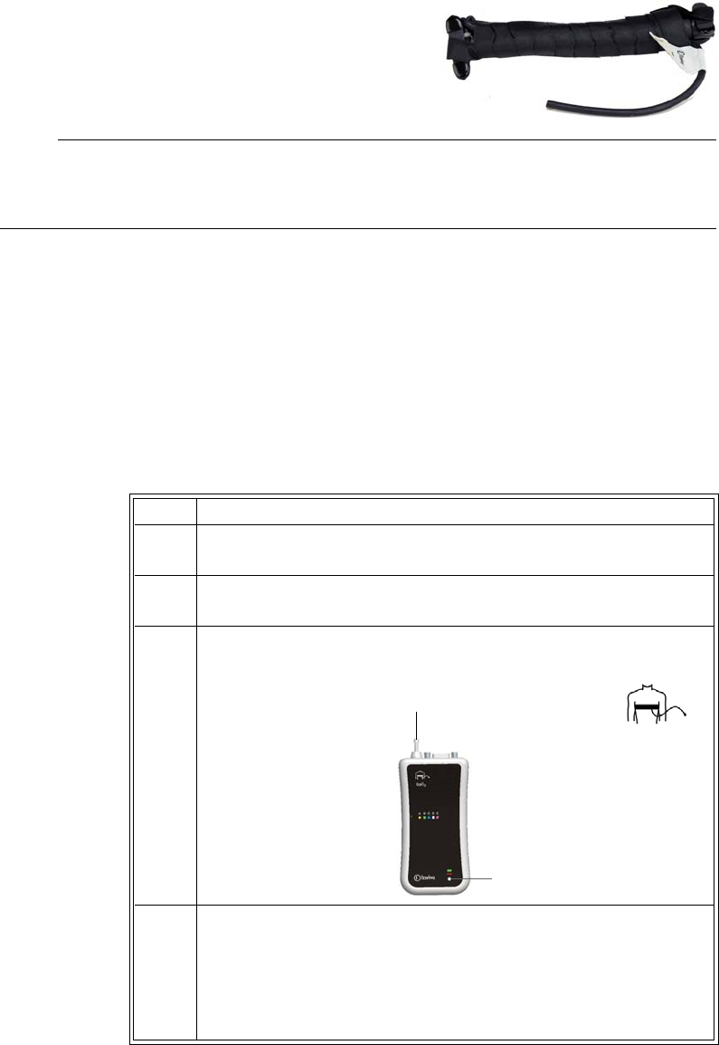
8‐2MonitoringRESPExpressionMR200InstructionsforUse
Respirationismonitoredbydetectingabdominalorchest
wallmotionusingapneumaticbellowsdevice.Notethat
therearenouseradjustableoptionsoralarmsfor
bellows‐derivedrespirationasitisnotintendedforvital
signmonitoring.
NOTE
If bellows respiration is turned on while the CO2 is on, bellows respiration data will appear in the
RESP VS box and CO2 respiration data will appear in the CO2 VS box.
Bellows Preparation
Respirationmeasurementsthataredeterminedusingthebellowsmethodmakechestwall
expansionveryimportantforaccuratemonitoringofapatient’sbreathing.Iftherespiratory
signalappearstoweakenbetweenscans,instructthepatienttobreathemoredeeplyduringthe
scantocreatemoremovementatthesensorsite.
Topositiontherespiratorysensor
Step Action
1Placethesensoronthepatient’supperabdomenorlowerchest
(whicheverexpandsmostduringinspiration).
2 Afterthepatienthasexhaled,placethevelcrostraparoundthe
patient’strunkandsecurethesensorsnuggly.
3Connecttheflexiblehosetothepneumaticrespirationportonthe
wSPO2module.
4Checkthestatusindicatorofthemodule;seepage2‐8:
• Solidgreen=Batterypowergood/Goodcommunication
• Flashinggreen=Batterypowergood/Nocommunication
• Solidred=Lowbatterypower/Goodcommunication
• Flashingred=Lowbatterypower/Nocommunication
Pneumatic respiration port
Status indicator
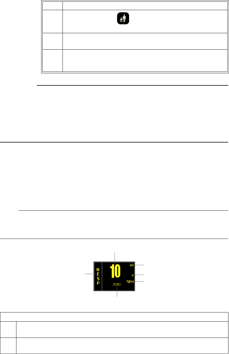
ExpressionMR200InstructionsforUseMonitoringRESP8‐3
CAUTIONS
• Avoid excessive bending of the flexible hose, as this will impair detection of the patient’s
respiration.
• Always apply the respiration sensor to the patient prior to connecting to the pneumatic
respiration port on the wSPO2 module. Connecting the pneumatic respiration sensor hose to
the port prior to applying the sensor to the patient can result in damage to the wSPO2
module.
Respiration VS Box
TheelementscontainedintheRESPVSboxaredescribedbelow.
NOTE
CO2-derived respiration is shown in the example below. When bellow-derived respiration is
selected, the related elements and VS box are displayed in white.
5PressthePatientkeyandthenselecttheappropriate
PATIENTtype(seepage3‐10fordetails).
6ChecktherespiratorysignalbeforethepatientisplacedintheMR
system.
7 PositionthepatientintheMRsystem.Ensurethattheflexiblehose
doesnotgetcaught(forexample,betweenthetabletopandthe
patientsupport).
Step Action
Definition
1 Is the high limit setting of the respiration alarm (not present with bellows respiration);
see page 8-5
2 Is the low limit setting of the respiration alarm (not present with bellows respiration);
see page 8-5
1
2
3
4
5
6

8‐4MonitoringRESPExpressionMR200InstructionsforUse
Changing RESP Alarm Limits
TochangetheRESPalarmlimitsettings
NOTE
To make global changes to the parameter alarm limit settings based upon the patient’s current
vital sign readings, see Setting Alarm Limits Globally on page 9-4.
3 Is the unit type for the respiration numeric data, where RPM is respirations per minute
4 Is the source used for the respiration monitoring, where CO2 is CO2-derived, and BEL
is bellows-derived; see page 8-6
5 Is the name of the vital sign/parameter
6 Is the respiration rate measurement (numeric)
Definition
Step Action
1TurnthecontrolknobtohighlighttheRESPVSbox(seepage8‐5)
andthenpresstheknob.
TheRESPmenuappears.Currentsettingsaredisplayed.
2TurnthecontrolknobtoALARMLIMITSandthenpresstheknob.
TheALARMLIMITSmenuappears.Currentsettingsaredisplayed;
seepage8‐5fordetails.
3Turntheknobtothel
oworhigh
settingandthenpresstheknob.
Thesettingisselected.
4Turntheknobtochangethesettingvalueandthenpresstheknob
tomakethechangeeffectiveandreturntothescrollingfunction.
Thesettingischanged.
5Tochangetheremainingsetting,repeatsteps3and4.

ExpressionMR200InstructionsforUseMonitoringRESP8‐5
RESP Menu
TheRESPmenuallowsyoutocontrolrespirationfunctionsandsettings.
TochangesettingsintheRESPmenu
ALARMLIMITS
ControlsthealarmlimitsettingsforCO2‐derivedrespiration.(Seethetableonpage9‐15fora
listing.)
Step Action
1TurnthecontrolknobtohighlighttheRESPVSboxandthenpress
theknob.
TheRESPmenuappears.Currentsettingsaredisplayed.
2TurnthecontrolknobtoselectanyofthefollowingRESPoptions
andthenpresstheknob:
ALARMLIMITS
SOURCE
Forinformationabouttheseoptions,seetheappropriatesections
below.
3Turntheknobtothedesiredsettingandthenpresstheknob.
4Tochangeothersettings,repeatsteps2and3.
5PresstheMainkeytoclosethemenu.
Alternative:TurntheknobtoRETURNandthenpresstheknob,or
waitapproximately60seconds.
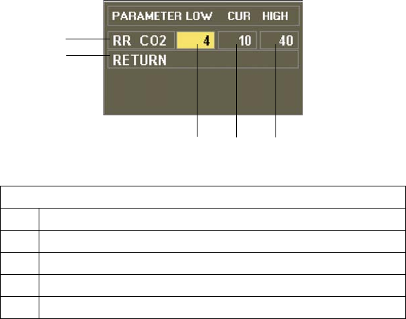
8‐6MonitoringRESPExpressionMR200InstructionsforUse
Tosetthealarmlimitsforrespiration
SeeChangingtheRESPAlarmLimitsonpage8‐4.
SOURCE
Selectsthesourceusedtoacquirerespirationmeasurements.
Thefollowingchoicesareavailable:
•CO2calculatestheratebymeasuringthetimeintervalbetweendetectedbreaths.(Default,
whenCO2‐equipped)
•BELcalculatestherateusingapneumaticbellowsthatmeasureschestorabdominal
movement.
Toselectthesourceforrespiration
EntertheRESPmenu.TurnthecontrolknobtoSOURCEandpresstheknob.Scrolltothedesired
sourceandpresstheknob.
Definition
1 Is the setting of the high alarm limit
2 Is the current measurement
3 Is the setting of the low alarm limit
4 Saves the settings and returns to the normal mode
5 Identifies CO2-derived respiration rate alarm limits
1
2
3
4
5

ExpressionMR200InstructionsforUseAlarms9‐1
CHAPTER 9
Alarms
TheMR200alertstheusertophysiological,technicalandstatusalarmswhichmayrequire
attentionorintervention.
Alarm Indications
Activealarmsconsistofbothvisualandaudiblecomponents,wherevisualindicationsare
providedbytheLCDandaudibleindicationsareprovidedbythespeaker.Thealarmtoneisuser‐
adjustablewithatypicalsoundpressurelevelof48–83decibels,andwillsoundafteradelayof
nomorethan4secondsfollowingavisualalarmindication,providedthatthealarmcondition
stillexistsafterthisdelay.
Alarm Safety Information
WARNINGS
• The monitor detects and responds almost immediately to most out-of-limits conditions,
except when averaging of the physiological signal is required to reduce unwanted noise
signals (for example, respiration rates and measurements derived from SPO2 signals.)
• Set the alarm volume based upon the ambient noise levels in the MR environment.
Some areas in the MR environment, such as the MR system room, may have ambient
noise levels louder than the maximum volume of the MR200. Therefore, displayed data
should be continuously monitored. Otherwise, if sound was inaudible, treatment of the
patient could be delayed. For visual alarms, adjust the position of the cart so that you
maintain a clear view of the display.
Status and Technical Alarms
Conditionsorevents(suchaslowbatteriesorhardwareerrors)canresultinalarms,which
generatemessagesthatwillbedisplayedinaparameter’sVSboxand/orinthesystemmessage
areaorthenotificationareaoftheLCD(seepage2‐13).
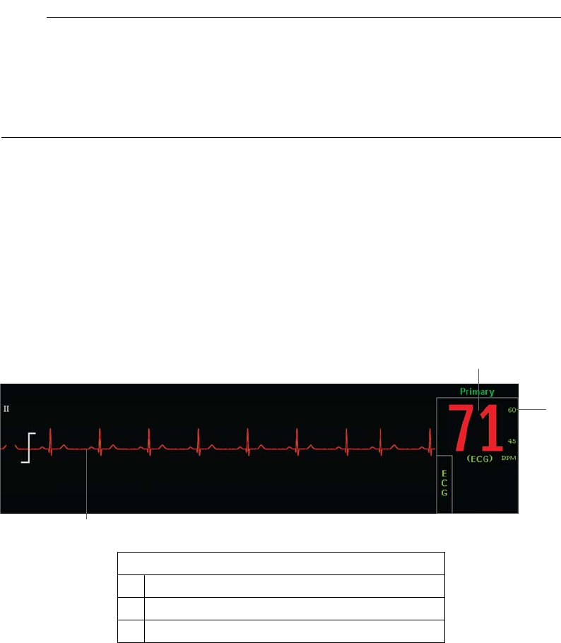
9‐2AlarmsExpressionMR200InstructionsforUse
NOTE
If a systemic failure of the processing hardware, software or communications renders an intended
task incomplete and unperformed, a watchdog circuit will automatically shutdown power to the
WPU. This will result in the removal of all patient data and displayed information, and a
continuous alarm will sound until power to the MR200 is turned off. If this problem persists,
contact technical support.
Physiological Alarms
Duringmonitoring,ifapatient’svitalsignmeasurementviolatesanactivealarmlimitsetting,a
physiologicalalarmwillbedeclared.Themonitorrespondsbysoundinganalarm(ifenabled)and
byflashingthenumericandwaveform(ifprovided)oftheviolatedparameterinredontheLCD.
Forexample,ifapatient’sheartrateclimbsto71BPM(whichisabovethesettingof60forthe
upperalarmlimitoftheECGvitalsign)analarmconditionisdeclared.
Enabling Print on Alarm
IftheMR200isconnectedtoanIP5printer,youcanautomaticallygenerateaprintoutwhena
physiologicalalarmoccurs.SeetheIP5IFUforsettingdetails.
Definition
1 Violated numeric
2 Violated alarm limit
3 Violated waveform
1
3
2

ExpressionMR200InstructionsforUseAlarms9‐3
Controlling Alarm Indications
WARNINGS
• Always respond promptly to any alarm condition; otherwise, treatment of the patient
could be delayed.
• You should ensure that the current alarm preset is appropriate prior to use on each
patient. Failure to do so may cause a lapse in patient monitoring.
• Setting the alarm limits to extreme values can render alarm monitoring useless. Also,
potential hazard can exist if different alarm monitoring settings are used for the same
or similar equipment in any single patient care unit. Ignoring these restrictions may
cause a lapse in patient monitoring.
TheMR200canbesettoprovidevisualalarmsignalsonly,orbothvisualandaudiblealarm
signals.AllsettingsintheALARMSmenu(exceptALARMSOUND)canbestoredandrecalled.
NOTE
If the MR200 is networked to an IP5, alarm indications occur at both the cart and the IP5; and
control of alarms, including sound level, is localized to the unit (cart or IP5) indicating the alarm
condition.
Latched and Unlatched Alarms
Whenanunlatchedalarmoccurs,thealarmstopswhentheconditionthattriggeredthealarm
ends.Forexample,ifabatterybecomeslow,thealarmendswhenthebatteryisreplaced.The
majorityofMR200alarmsareunlatched.
Ontheotherhand,alatchedalarmcontinuesevenaftertheconditionthatcausedthealarmwas
resolved.LOWPERFisanexampleofalatchedalarm.IfLOWPERFoccursbutthenreturnsto
withinanormalrange,thealarmwillcontinuetodisplaytonotifytheclinicianoftheSPO2event.
(Toclearalatchedalarm,seepage9‐7.)
Showing or Hiding Current Alarm Limits
CurrenthighandlowalarmlimitsaredisplayedintheVSboxofeachmonitoredparameterby
default(exceptbellows‐derivedrespiration).
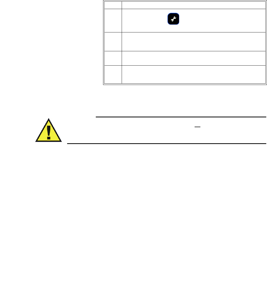
9‐4AlarmsExpressionMR200InstructionsforUse
Tochangethealarmlimitdisplay
Setting Alarm Limits
WARNING
Alarm limits can be set to a wide range of values, including off. It is the responsibility of the
operator of the MR200 to ensure that alarm limit values appropriate for each patient are
established and set. Failure to do so may cause a lapse in patient monitoring.
TheMR200providesversatilemethodstocontrolthesettingsforthepatientparameteralarms.
Eachpatientparameter(withtheexceptionofbellowsrespiration)hasalowandhighalarmlimit
setting(seethetableonpage9‐14),whichcanbechangedmanuallyorautomatically,unlessthe
parameterisoff.
Setting Alarm Limits Globally
Globalchangescanbemadetoallparameteralarmlimitsettingsbaseduponthepatient’s
currentvitalsignreadingusingCALCULATEALL;seepage9‐10fordetails.Duringthisprocess,ifa
patient’smonitoredvalueissohighorlowthatitwillexceedthealarmlimitrangeforthe
parameter,therespectivealarmlimitwillbesettothehighestorlowestpossiblevalue,butnot
tooff.Forexample,ifafterperformingCALCULATEALL,apatient’sSPO2upperalarmlimitwas
automaticallysetto99(thehighestallowablevalue),thenanalarmwillbegeneratedifthe
patient’sreadingreaches100.Ifyouwanttoturnofftheupperlimit,thenitmustbedone
manually;seeSettingAlarmLimitsIndividuallyonpage9‐5.
AlsonotethatwhenusingCALCULATEALLitwillalmostalwaysresultinalowerSpO2limitthan
thedefaultsetting.ForapatientthathasanSpO2readingof99%thenewupperlimitwillbe99,
butthenewlowerlimitwillbe79(insteadof85)ataCALCULATEALLoffsetof20%(factory
default).
Step Action
1PresstheSETUPkey.
TheSETUPmenuappears.
2WithALARMSETUPhighlighted,pressthecontrolknob.
TheALARMSmenuappears.Currentsettingsaredisplayed.
3TurntheknobtoLIMITSDISPLAYandthenpresstheknob.
4Scrolltothedesiredsettingandpresstheknob.
Thesettingisselected.

ExpressionMR200InstructionsforUseAlarms9‐5
Toadjustthealarmlimitsettingsforallmonitoredparameters
Setting Alarm Limits Individually
IndividualparameteralarmlimitsettingscanbecontrolledintheALARMSmenuorinthe
parameter’smenu(seetheappropriatemonitoringchapterfordetails).
Step Action
1WiththepatientconnectedtotheMR200andwith
thedesiredparametersturnedon,presstheSETUPkey.
TheSETUPmenuappears.
2WithALARMSETUPhighlighted,pressthecontrolknob.
TheALARMSmenuappears.Currentsettingsaredisplayed.
3TurntheknobtoUPPERWINDOWandthenpresstheknob.
Thecurrentsettingishighlighted.
4Scrolltothedesiredpercentageandpresstheknob.Thefollowing
choicesareavailable:
5%
10%
15%
20%
30%
Thesettingisselected.
5TurntheknobtoLOWERWINDOWandthenpresstheknob.
Thecurrentsettingishighlighted.
6Scrolltothedesiredpercentageandpresstheknob.Thefollowing
choicesareavailable:
5%
10%
15%
20%
30%
Thesettingisselected.
7ScrolltoCALCULATEALLthenpresstheknob.
Allactivealarmlimitsettingsarechanged.

9‐6AlarmsExpressionMR200InstructionsforUse
Toadjustthealarmlimitsettingsforasingleparameter(usingtheALARMSmenu)
Restoring Default Alarm Limit Settings
Thesystemautomaticallyrestoresdefaultvalueswhenyouchangethepatienttype.(Seepage9‐
15forthedefaultsettings.)
Torestorethealarmlimitstothedefaultsettings
Step Action
1PresstheSETUPkey.
TheSETUPmenuappears.
2
WithALARMSETUPhighlighted,pressthecontrolknob.
TheALARMSmenuappears.Currentsettingsaredisplayed.
3WithSETINDIVIDUALhighlighted,presstheknob.
Thecursorhighlightsalowalarmlimitsettinginthemenu.
4Turnthecontrolknobtoselectthealarmlimittobechangedand
thenpresstheknob.
Thesettingisselectedandthehighlightingchangescolor.
5Turntheknobtochangethesettingvalueandthenpresstheknob
tomakethechangeeffectiveandreturntothescrollingfunction.
Thesettingischanged.
6Tochangeanyremainingsettings,repeatsteps4and5.
Step Action
1WithamonitoredpatientconnectedtotheMR200,pressthe
SETUPkey.
TheSETUPmenuappears.
2WithALARMSETUPhighlighted,pressthecontrolknob.
TheALARMSmenuappears.Currentsettingsaredisplayed.
3TurntheknobtoDEFAULTLIMITSandpresstheknob.
Thealarmsettingsarereturnedtothedefaultvalues.
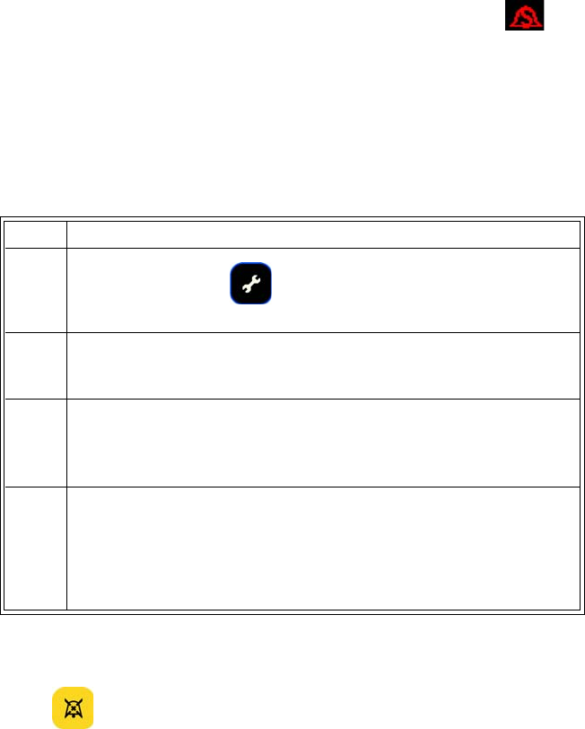
ExpressionMR200InstructionsforUseAlarms9‐7
Controlling the Alarm Sound
Thealarmvolumecanbeadjusted.Inaddition,thealarmsoundcanbetemporarilydisabledby
pressingtheSilencekey,oritcanbepermanentlydisabledintheALARMSmenu(althoughthe
numericandwaveformwillcontinuetoflashwhiletheparameterviolatesitsalarmlimit).
Oncesilenced,analarmwillnotsoundagainforanyreasonaslongasthatconditioncontinues.
Onlyadifferentparameterviolationwillcausethealarmsoundtoreactivate.(Forexample,ifa
patient’sheartratedropsbelowthesetlimitandthatalarmissilenced,thealarmwillnotsound
forthatconditionagainunlesstheheartratereturnstowithinlimitsandthendropsbelowthe
limitagain.)
AnactivesilencedalarmmaynotbeaccompaniedbyanALARMSILENCEDmessageor
symboliftheAlarmHoldsequencehasbeenactivated,orifasubsequentalarmhasoccurredand
self‐corrected.
Adjusting the Alarm Volume
Toincreaseordecreasethealarmvolume
Silencing the Alarm
PressingtheSilencekeyduringanalarmwillsilenceallactivealarms,dependinguponthe
TYPEsetting(seepage9‐13):
•IfUNLATCHED,theSilencekeywillmutethealarmsoundand,whiletheviolation
continues,thedisplayednumericandwaveformoftheparameterwillflashinred.Any
newalarmconditionwillcausethealarmtoreactivate.Oncetheparameterreturnsto
Step Action
1PresstheSETUPkey.
TheSETUPmenuappears.
2TurntheknobtoMONITORSETUPandpressthecontrolknob.
TheMONITORmenuappears.Currentsettingsaredisplayed.
3TurntheknobtoSOUNDADJUSTandpresstheknob.
TheSOUNDADJUSTmenuappears.Thecurrentsettingsare
displayed.
4TurntheknobtoALARMVOLUMEandpresstheknob.
1–10(48–83decibels,typical)
Thecurrentsettingishighlighted.Forverificationduring
adjustment,anacknowledgementissoundedattheselectedlevel.

9‐8AlarmsExpressionMR200InstructionsforUse
withinitsalarmlimit,thenumericandwaveformwillstopflashingandreturntotheir
designatedcolor.
•IfLATCHED,whiletheparametercontinuestoviolateitslimit,theSilencekeywillmutethe
alarmsound.Thenumericandwaveformwillcontinuetoflashinredaftertheparameter
returnstowithinitsalarmlimits,thenuponpressingtheSilencekeyasecondtimethe
numericflashingstopsandtheaudiblealarmisplacedintoAlarmHoldmode.
Tosilenceaudiblealarms
PresstheSilencekey.
Alarm Hold Mode
AlarmHoldcanbeusefultotemporarilysilencealarmswhenchangingECGleadsorforotheruser
activitiesthatmightcausea“false”alarm.
AlarmHoldisindicatedwhenisdisplayedandSOUNDONHOLDappearsinthesystem
messageareawithacountdowntimerstartingat120seconds.Theholdperiodisnotuser‐
adjustable.Duringtheholdperiod,theaudiblealarmwillbesuspendedforanynewalarm
conditionsthatoccur.
ToactivateAlarmHold
PresstheSilencekey:
•Ifthealarmisnotsounding,pressingthekeyenablesholdmode.
•Ifthealarmissounding,pressingthekeytwiceenablesholdmode.
Aftertheholdperiodexpires,thesoundforthephysiologicalalarmsarerestored.Alarm
conditionspreviouslysilencedbypressingtheSilencekeywillnottriggeranaudiblealarmwhen
theholdperiodtimesout.
TodeactivateAlarmHold
•Waituntilthecountdowncompletes;or,
•PresstheSilencekey.
ALARMS Menu
TheALARMSETUPoption(intheSETUPmenu)openstheALARMSmenu,whichcontains
optionsforsetupandcontrolofthevitalsignalarms.
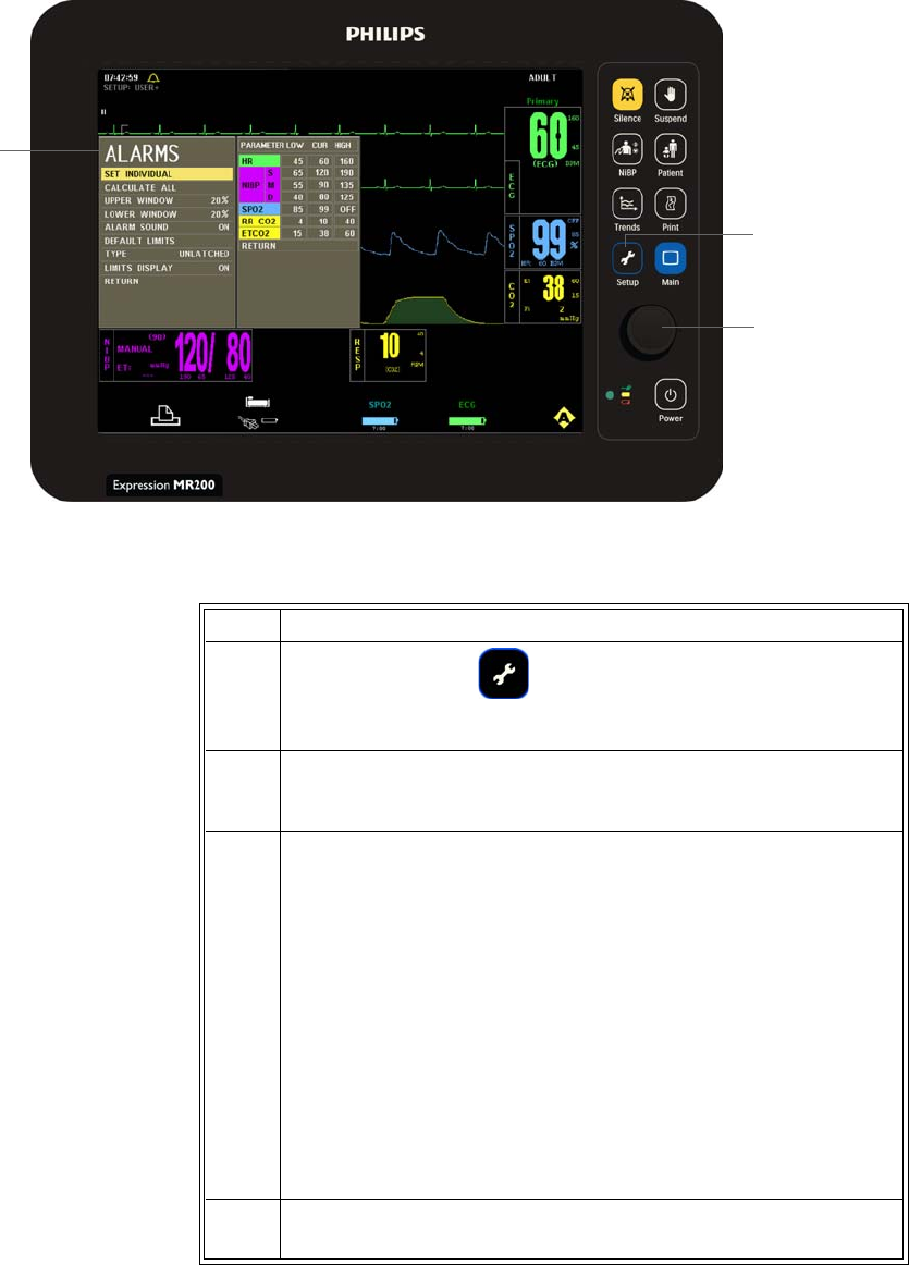
ExpressionMR200InstructionsforUseAlarms9‐9
TochangesettingsintheALARMSmenu
Setup key
Control knob
ALARMS
menu
Step Action
1PresstheSETUPkey.
TheSETUPmenuappears.
2
WithALARMSETUPhighlighted,pressthecontrolknob.
TheALARMSmenuappears.Currentsettingsaredisplayed.
3Turnthecontrolknobtoselectanyofthefollowingsystem‐wideor
individualalarmoptionsandthenpresstheknob:
SETINDIVIDUAL
CALCULATEALL
UPPERWINDOW
LOWERWINDOW
ALARMSOUND
DEFAULTLIMITS
TYPE
LIMITSDISPLAY
Forinformationabouttheseoptions,seetheappropriatesections
below.
4Turntheknobtothedesiredsettingandthenpresstheknob.
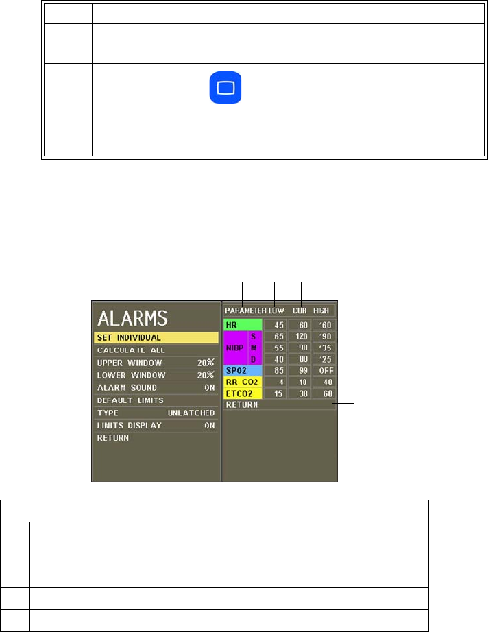
9‐10AlarmsExpressionMR200InstructionsforUse
SET INDIVIDUAL
Controlsthealarmlimitsettingsforindividualparameters.
Toindividuallyadjustthealarmlimitsettings
Seepage9‐5.
CALCULATE ALL
CalculatesnewalarmlimitsettingsforallactiveparametersaccordingtothesettingsinUPPER
WINDOWandLOWERWINDOWoptions(seebelow).Correspondinglowandhighcalculations
willbeperformedforeachactiveparameter.
5Tochangeotheroptions,repeatsteps3and4.
6PresstheMainkeytoclosethemenu.
Alternative:TurntheknobtoRETURNandthenpresstheknob,or
waitapproximately60seconds.
Definition
1 Identifies the parameter
2 Are the current settings of the low alarm limits
3 Are the current readings of the patient
4 Are the current settings of the high alarm limits
5 Exits the menu
Step Action
1234
5

ExpressionMR200InstructionsforUseAlarms9‐11
Togloballyadjustthelowandhighalarmlimitsettings
SeeSettingAlarmLimitsGloballyonpage9‐4.
NOTE
If a patient’s monitored value is so high or low that it exceeds the alarm limit range for the
parameter, the respective alarm limit will be set to the highest or lowest possible value, but not to
off, as indicated in the table on page 9-14.
UPPER WINDOW
SetsapercentvalueusedtocalculatethehighalarmlimitswhenCALCULATEALLisselected.The
currentparametervalueisbracketedwiththepercentagessetinthismenuandtheLOWER
WINDOWsetting.
Thefollowingchoicesareavailable:
•5%
•10%
•15%
•20%(Default)
•30%
Tosettheuppercalculationvalue
EntertheALARMSmenu.TurnthecontrolknobtoUPPERWINDOWandpresstheknob.Scrollto
thedesiredpercentageandpresstheknob.
LOWER WINDOW
SetsapercentvalueusedtocalculatethelowalarmlimitswhenCALCULATEALLisselected.The
currentparametervalueisbracketedwiththepercentagessetinthismenuandtheUPPER
WINDOWsetting.
Thefollowingchoicesareavailable:
•5%
•10%
•15%
•20%(Default)
•30%
Tosetthelowercalculationvalue
9‐12AlarmsExpressionMR200InstructionsforUse
EntertheALARMSmenu.TurnthecontrolknobtoLOWERWINDOWandpresstheknob.Scroll
tothedesiredpercentageandpresstheknob.
ALARM SOUND
WARNING
The alarm sound can be turned off. Always ensure that the alarm sound setting is
appropriate for each patient. The alarm sound volume is adjustable for suitability to various
clinical environments. When you use the MR200, always ensure that the alarm sound can be
heard above the ambient noise level. Failure to do so may cause a lapse in patient
monitoring.
Controlstheaudioalertforthealarms(identicaltoandinteractivewithMONITOR>SOUND
ADJUST>ALARMS;seepage3‐8).
Thefollowingchoicesareavailable:
•ONturnsonthealarmsound,whereindicatesthatthesoundhasbeenenabled.
(Default)
•OFFturnsoffthealarmsound,whereindicatesthatthesoundhasbeendisabled.
(Onlythealarmsoundwillbedisabled;thevisualalertfromthesourceoftheviolationstill
flashesinred.)
Tosetthealarmsound
DEFAULT LIMITS
Automaticallysetsthelowandhighalarmlimitsforallparameterstothealarmlimitdefaults
(seethetableonpage9‐15).
Tosetthealarmlimitsettingstothedefaultlimits
SeeRestoringDefaultAlarmLimitSettingsonpage9‐6.
Step Action
1PresstheSETUPkey.
TheSETUPmenuappears.
2
WithALARMSETUPhighlighted,pressthecontrolknob.
TheALARMSmenuappears.Currentsettingsaredisplayed.
3TurnthecontrolknobtoALARMSOUNDandthenpresstheknob:
4Turntheknobtothedesiredsettingandthenpresstheknob.

ExpressionMR200InstructionsforUseAlarms9‐13
TYPE
DeterminestheresponseofanalarmwhentheSilencekeyispressed.
Thefollowingchoicesareavailable:
•UNLATCHEDalarmsceaseaudioandvisualalertsiftheviolatedparameterreturnswithin
itslimitsoriftheSilencekeyispressed.(Default)
•LATCHEDalarmsceaseaudioandvisualalertsonlywhentheSilencekeyispressed.
Tosetthetypeofthealarm
EntertheALARMSmenu.TurnthecontrolknobtoTYPEandpresstheknob.Scrolltothedesired
settingandpresstheknob.
LIMITS DISPLAY
DeterminesifthealarmlimitsettingsareshownintheVSboxes.
Thefollowingchoicesareavailable:
•ONdisplaysthealarmlimitsettings.(Default)
•OFFhidesthealarmlimitsettings.
Tocontrolthepresenceofthealarmlimitsettings
EntertheALARMSmenu.TurnthecontrolknobtoLIMITSDISPLAYandpresstheknob.Scrollto
thedesiredsettingandpresstheknob.
Testing Alarms
Toverifythatthealarmsystemisworking
Step Action
1Withthemonitorturnedonandnotinsuspendmode,makesureall
alarmsareenabled(ALARMSOUNDisnotoff,silenced,oronhold).
2MakesurethelowerSPO2alarmlimitisnotsettoOFF.

9‐14AlarmsExpressionMR200InstructionsforUse
NOTE
If a problem with the alarm sound or messaging system is suspected, discontinue use of the
MR200 and refer it to authorized service personnel for evaluation.
Adjustable Alarm Limit Ranges
Withtheexceptionofbellowsrespiration,eachparameteralarmhasadjustablelimitsasindicatedin
tablebelow
.
TheMR200preventscrossoveroflowandhighalarmlimitsettings;and,ifaparameter
hasbeenturnedoff,itsalarmlimitswillbeoff.
3VerifythewSPO2modulestatusbycheckingthestatusindicator:
• Solidgreen=BatterypowerOK/Goodcommunication
• Flashinggreen=BatterypowerOK/Nocommunication
• Solidred=Lowbatterypower/Goodcommunication
• Flashingred=Lowbatterypower/Nocommunication
4PlacetheSPO2attachmentonyourfingerandwaitforavalueto
appearintheSPO2VSbox.
5 Removetheclipfromyourfinger.
6
EnsurethattheNON‐PULSATorPROBEOFFmessageappearsin
theSPO2VSbox,thewaveformflatlinesandturnsred,the
numericflashesinred,andthealarmtonesounds.
Step Action
Adjustable Alarm Limit Ranges
Vital Sign or
Parameter Unit Low Alarm Limit * High Alarm Limit *
Minimum Maximum Minimum Maximum
Heart Rate BPM Off, 30 249 60 249, Off
CO2 (End-tidal)** mmHg
kPa
Off, 5
Off, 0.7
60
8.0
5
0.7
80, Off
10.7, Off
CO2 Respiration RPM Off, 4 40 20 99, Off
NiBP Systolic, Adult mmHg
kPa
Off, 46
Off, 6.1
254
33.9
46
6.1
254, Off
33.9, Off
NiBP Systolic, Pediatric mmHg
kPa
Off, 46
Off, 6.1
254
33.9
46
6.1
254, Off
33.9, Off
NiBP Systolic, Neonate mmHg
kPa
Off, 46
Off, 6.1
124
16.5
46
6.1
124, Off
16.5, Off

ExpressionMR200InstructionsforUseAlarms9‐15
*Allow±oneleastsignificantdigittoaccommodatetheround‐offerrorforcalculatedvalues.
**HighalarmlimitforinspiredCO2isfixed.
Alarm Limit Defaults
Intheeventofpowerloss,anyalarmlimitsettingsthatwerechangedwillbelost.Allsettingsthat
mayhavebeenmodifiedtosuitaparticularpatientshouldbeconfirmedbeforemonitoring.
Atpowerup,theMR200willautomaticallysetallalarmlimitsasdeterminedbythesettinginthe
DEFAULTSETUPSmenu;seepage3‐13.
NiBP Mean, Adult mmHg
kPa
Off, 26
Off, 3.5
239
31.9
26
3.5
239, Off
31.9, Off
NiBP Mean, Pediatric mmHg
kPa
Off, 26
Off, 3.5
239
31.9
26
3.5
239, Off
31.9, Off
NiBP Mean, Neonate mmHg
kPa
Off, 26
Off, 3.5
94
12.5
26
3.5
94, Off
12.5, Off
NiBP Diastolic, Adult mmHg
kPa
Off, 16
Off, 2.1
224
29.9
16
2.1
224, Off
29.9, Off
NiBP Diastolic, Pediatric mmHg
kPa
Off, 16
Off, 2.1
224
29.9
16
2.1
224, Off
29.9, Off
NiBP Diastolic, Neonate mmHg
kPa
Off, 16
Off, 2.1
84
11.2
16
2.1
84, Off
11.2, Off
SPO2 Percent Off, 50 99 70 99, Off
Adjustable Alarm Limit Ranges
Vital Sign or
Parameter Unit Low Alarm Limit * High Alarm Limit *
Minimum Maximum Minimum Maximum
Factory Default Alarm Limits*
Vital Sign or
Parameter Unit
Neonate Pediatric Adult
Low
Limit
High
Limit
Low
Limit
High
Limit
Low
Limit
High
Limit
Heart Rate BPM 90 210 75 160 45 160
CO2 (End-tidal) mmHg
kPa
30
4.0
45
6.0
15
2.0
60
8.0
15
2.0
60
8.0
CO2 Respiration RPM 30 70 4 40 4 40
NiBP Systolic mmHg
kPa
70
9.3
100
13.3
70
9.3
120
16.0
65
8.7
190
25.3
NiBP Mean mmHg
kPa
40
5.3
90
12.0
50
6.7
90
12.0
55
7.3
135
18.0

9‐16AlarmsExpressionMR200InstructionsforUse
*Allow±oneleastsignificantdigittoaccommodatetheround‐offerrorforcalculatedvalues.
Listing of Alarms
Allalarmsarecategorizedashighpriority.
WARNING
If, during use, an alarm condition listed below results in a loss of patient monitoring
capability, employ an alternate means as needed to prevent a lapse in patient monitoring;
otherwise, treatment of the patient could be delayed.
NOTE
In the tables below, abbreviations used in the Type column have these meanings:
C = conditional; L = latched; S = selectable; and, U = unlatched.
Status and Technical Alarm Indications and Messages
Thefollowingtablecontainsalistingofthestatusandtechnicalalarmindicationsandmessages.
NiBP Diastolic mmHg
kPa
35
4.7
50
6.7
40
5.3
70
9.3
40
5.3
125
16.7
SPO2 Percent 90 Off 90 Off 85 Off
Factory Default Alarm Limits*
Vital Sign or
Parameter Unit
Neonate Pediatric Adult
Low
Limit
High
Limit
Low
Limit
High
Limit
Low
Limit
High
Limit
Displayed Message/
Indication
Message
Location Type Probable Cause Recommended Action
ALARM SILENCED System message
area
NOTE
No alarm sound
generated
U The Silence key was
pressed.
Wait until the 120-second countdown
completes or press the Silence key.
BAD PROBE SPO2 VS box U The SPO2 sensor is
defective.
Replace the SPO2 sensor.

ExpressionMR200InstructionsforUseAlarms9‐17
CHANGE NiBP CUFF Notification
area
L The PATIENT type was
changed and this message is
displayed as a reminder.
Ensure the correct cuff size is used for
the patient.
CHECK ALARM VOL System message
area
U Power was just turned on,
settings were recalled, or an
adjustment was made to a
sound setting
No action necessary. Allow the process
to complete.
CHECK CO2
SAMPLING LINE
Notification
area
U Reduced flow has been
detected by the CO2 system.
Check for pinches or obstructions in
the sampling line. Clear any pinch, or
replace the accessory if necessary.
COMM ERR NiBP VS box L NiBP internal error Discontinue use of NiBP and contact
technical support.
CO2 CAL FAIL Notification
area
CCO2 calibration has failed. Retry calibration. If the problem
persists, contact technical support.
CO2 Hardware Fail Notification
area
CCO2 module was not found
during initialization
Contact technical support.
CO2 OUT OF RANGE Notification
area
U The calculation value is greater
than the upper CO2 limit .
Perform patient readings to confirm
physiological condition.
CO2 SENSOR FAULTY Notification
area
LCO2 bench detected a
hardware or sensor error.
Contact technical support.
CO2 SENSOR OVER
TEMP
Notification
area
UCO2 sensor is above the
specified operating
temperature.
Confirm that the MR200 is operating
within required environmental
conditions (see Appendix A). If outside
the specified range, move the cart to an
area that is within limits.
If the problem persists, stop all
monitoring activities and contact
technical support.
CO2 WARMING UP Notification
area
UDisplayed during the warm-up
period of the CO2 module
Allow the module to complete its
warm-up cycle, about two minutes.
CO2 ZERO REQUIRED Notification
area
U Zero calibration of the CO2
module is needed
Perform a zero calibration; see page 7-
11.
DEFL TO NiBP VS box L NiBP deflation has timed out. • Check the patient.
• Check for proper cuff size and
placement.
• Check the cuff and hoses for
pinching.
• If the message persists, contact
technical support.
ERRATIC SPO2 VS box U The SPO2 clip (or grip) is not
properly applied to the
patient, is not properly
positioned, or the sensor is
faulty.
• Check the alignment of the clip (or
grip).
• Replace the SPO2 sensor.
• If the message persists, contact
technical support.
HW ERR NiBP VS box L NiBP hardware failure Discontinue use of NiBP and contact
technical support.
Displayed Message/
Indication
Message
Location Type Probable Cause Recommended Action

9‐18AlarmsExpressionMR200InstructionsforUse
HW FAIL NiBP VS box L A hardware or other error
has occurred in the NiBP
system.
Discontinue use of NiBP and contact
technical support.
HW FAIL SPO2 VS box L A hardware or other error
has occurred in the wSPO2
module.
Replace the wSPO2 module. If the
failure persists, immediately remove
the MR200 and wSPO2 module from
service and contact technical support,
as the system must not be used on any
patient requiring SPO2 measurement.
INFL TO NiBP VS box L NiBP inflation has timed out. • Check the patient.
• Check the cuff and hoses for
pinching or leaks.
• If the message persists, contact
technical support.
Internal CO2 Occlusion Notification
area
U The internal filter has become
polluted or disconnected.
Contact technical support.
INTRFERNCE SPO2 VS box U Interference due to
misalignment of the
attachment’s light source and
receiver, or incorrect
positioning of the attachment
on the patient.
• Ensure that the module is placed
outside of the MR bore.
• Reposition the wSPO2 module (see
page 5-5.
• Check the alignment of the clip (or
grip).
• Try a different limb or site.
• Replace the clip (or grip).
LEAD FAIL ECG trace
area
NOTE
If the heart
rate source is
set to ECG, no
HR value will
be displayed in
the ECG VS
box.
U A faulty or disconnected
ECG lead is detected.
NOTES
An inoperative ECG
parameter or wECG module
is indicated by absence of an
ECG waveform and a
simultaneous Lead Fail
alarm.
Ensure all clip leads are connected to
the Quadtrode electrode and that the
ECG lead cable is properly connected
to the wECG module. Also, ensure
that the wECG module has sufficient
battery power.
If the problem persists, replace the
ECG lead cable.
Displayed Message/
Indication
Message
Location Type Probable Cause Recommended Action

ExpressionMR200InstructionsforUseAlarms9‐19
LEAD SATURATION ECG trace
area
NOTE
If the heart
rate source is
set to ECG, no
HR value will
be displayed in
the ECG VS
box.
U Reported within 10 seconds,
the baseline offset of the ECG
input signal is too large for the
system to process and display
the waveform.
Replace the Quadtrode electrode.
LOW PERF SPO2 VS box
NOTE
No alarm
sound
generated
U Accuracy may be
compromised due to low
perfusion. The tissue at the
site may be too opaque, thick
or cold.
• If the attachment is positioned on
the finger, check the fingernails for
nail polish, long or artificial
fingernails. Remove any fingernail
polish completely.
• Try another location, like a toe.
• Try rubbing or warming the limb.
Module Not Calibrated NiBP VS box L NiBP is not calibrated. Contact technical support.
MSMT FAIL NiBP VS box L The NiBP measurement has
failed.
• Check the patient.
• Check for proper cuff size and
placement.
• Check the cuff and hoses for
pinching or leaks.
• If the message persists, contact
technical support.
MSMT TO NiBP VS box L The NiBP measurement has
timed out.
• Check the patient.
• Check for proper cuff size and
placement.
• Check the cuff and hoses for
pinching or leaks.
• If the message persists, contact
technical support.
NiBP:
COMMUNICATION
ERROR
Notification
area L
Same as COMM ERR See COMM ERR for details.
NiBP: DEFLATION
TIMEOUT
Notification
area
L Same as DEFL TO See DEFL TO for details.
NiBP: HARDWARE
ERROR
Notification
area
L Same as HW ERR See HW ERR for details.
NiBP: INFLATION
TIMEOUT
Notification
area
L Same as INFL TO See INFL TO for details.
Displayed Message/
Indication
Message
Location Type Probable Cause Recommended Action

9‐20AlarmsExpressionMR200InstructionsforUse
NiBP: MEASUREMENT
FAILED
Notification
area
L Same as MSMT FAIL See MSMT FAIL for details.
NiBP: MEASUREMENT
TIMEOUT
Notification
area
L Same as MSMT TO See MSMT TO for details.
NiBP: OVER
PRESSURE
Notification
area
L Same as OVR PRESS See OVR PRESS for details.
NiBP: PRESSURE
CORRECTION ERROR
Notification
area
L Same as PRESS CORR See PRESS CORR for details.
NiBP: RESIDUAL
PRESSURE
Notification
area
L Same as RESID PRESS.See RESID PRESS for details.
NO PROBE SPO2 VS box U The SPO2 sensor is not
present or is improperly
connected to the wSPO2
module.
Check the connection of the sensor to
the module. Reconnect it; or if the
connection is good, replace the sensor.
NOISE SPO2 VS box U Excessive patient motion;
MRI scan sequence; or,
electrical interference is
being experienced by the
SPO2 system.
• Check for patient motion, especially
at the monitored site.
• Ensure that the module is placed
outside of the MR bore.
• Ensure the clip (or grip) is
positioned so that it is not exposed
to excessive levels of ambient light.
NON-PULSAT SPO2 VS box U The patient’s pulse is too
weak for the system to
report reliable SPO2
saturation and pulse
measurements.
• Check the patient’s condition.
• Check the clip (or grip) position and
alignment on the patient then re-
position or re-apply as necessary
• Try a different limb or site.
OVERSCALE ECG trace
area
NOTE
No alarm
sound
generated
UThe ECG waveform is too
large and the peaks are being
clipped.
Reduce the waveform size by choosing
a setting in the ECG Scale menu.
OVR PRESS NiBP VS box L NiBP has exceeded the
allowed pressure for the
patient type.
• Ensure that the patient is
immobilized and not applying
pressure to the cuff.
• Check the cuff condition and
placement on the patient.
• Make sure that the hose is not
pinched.
• If the message persists, contact
technical support.
Displayed Message/
Indication
Message
Location Type Probable Cause Recommended Action

ExpressionMR200InstructionsforUseAlarms9‐21
PERFORMING CO2
ZERO
Notification
area
UDisplayed while performing
CO2 zeroing.
No action necessary. Allow the process
to complete.
PRESS CORR NiBP VS box L An NiBP pressure correction
error has been detected.
• Ensure that the patient is
immobilized and not applying
pressure to the cuff.
• Check the cuff condition and
placement on the patient.
PROBE OFF SPO2 VS box
NOTE
Alarm sounds
only if
reported after
a valid
numeric is
displayed.
U The SPO2 attachment is not
properly applied to the
patient.
Check the position of the clip (or grip)
and its alignment on the patient;
reposition or reapply the clip (or grip).
PULSE? SPO2 VS box U The clip (or grip) may not be
applied optimally; or, the
tissue at the application site
may be too opaque.
• Check the alignment of the clip (or
grip).
• Try a different limb or site.
RESID PRESS NiBP VS box L Residual pressure remains in
the NiBP system.
Disconnect the NiBP hose and restart
the procedure.
REAL TONES
DISABLED Notification
area
NOTE
No alarm
sound
generated
U Displayed when in the
SOUND ADJUST >
ALARMS menu
Exit the menu.
SEARCHING SPO2 VS box
NOTE
Alarm sounds
only if
reported after
a valid
numeric is
displayed.
U The SPO2 attachment was
just applied to the patient or
it has shifted position since
attachment.
• If SPO2 was just applied, allow
about 20 seconds for the system to
lock on to a good pulse.
• Check the clip (or grip) position and
reposition it if necessary.
• Replace the SPO2 sensor.
• If the message persists, contact
technical support.
Displayed Message/
Indication
Message
Location Type Probable Cause Recommended Action

9‐22AlarmsExpressionMR200InstructionsforUse
SIMULATION System message
area
NOTE
No alarm sound
generated
L Simulation mode is running. Cycle power off and on.
SOUND ON HOLD System message
area
NOTE
No alarm sound
generated
U Power was turned on, or the
Silence key was pressed.
Wait until the 120-second countdown
completes or press the Silence key.
SUSPENDED System message
area
NOTE
No alarm sound
generated
U The Suspend key was
pressed and alarms are now
suspended.
Press the Suspend key to exit the
mode.
WARNING
Move monitor away
from magnet. NiBP
and CO2 (if installed)
have been shut down.
Dialog box U The gauss limit has been
exceeded, and now NiBP and
CO2 can no longer function.
Position the MR200 per the product
labeling; see page 2-6.
WARNING
Persistent CO2
occlusion detected.
Please clear occlusion
and press OK to
resume using CO2
Dialog box U Reduced flow has been
detected by the CO2 system
for over 2 minutes.
Check for pinches or obstructions in
the sampling line. Clear any pinch, or
replace the accessory if necessary.
Afterward, press OK to restart the
CO2 parameter.
If the message persists, contact technical
support.
WRONG PRB SPO2 VS box U The SPO2 sensor connected
to the wSPO2 module is not
the correct type.
Attach the correct sensor to the
module.
Communication
and power
status display
area
U No communication between
the cart and wSPO2 module
Ensure that the wSPO2 module is set to
the same network channel as the cart. If
both are the same, use an alternate
setting.
If the indication persists, contact
technical support.
Displayed Message/
Indication
Message
Location Type Probable Cause Recommended Action
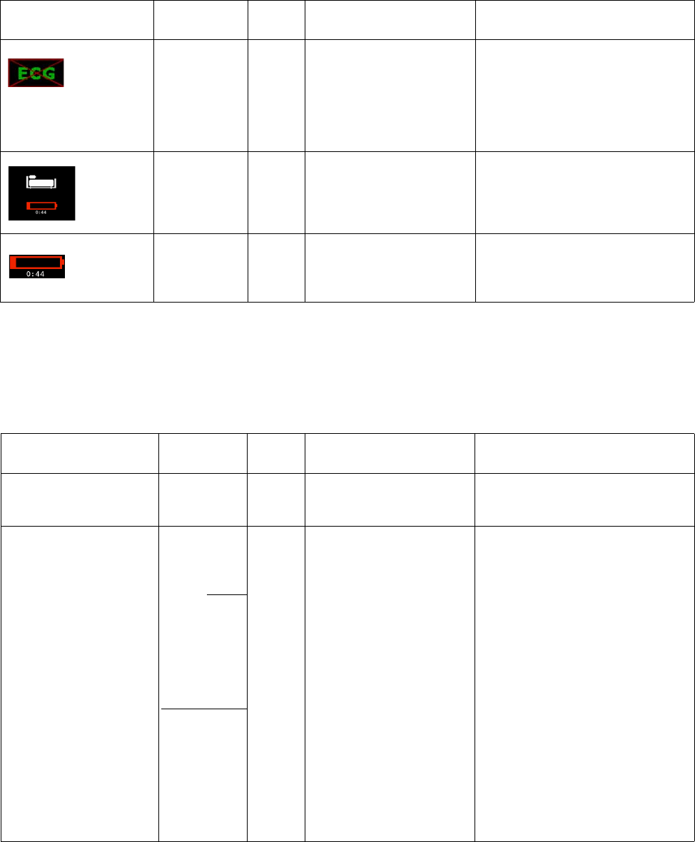
ExpressionMR200InstructionsforUseAlarms9‐23
Physiological Alarm Indications and Messages
Thefollowingtablecontainsanalphabeticallistingofphysiologicalalarmindicationsand
messages.
Communication
and power
status display
area
U No communication between
the cart and wECG module
Ensure that the wECG module is set to
the same network channel as the cart. If
both are the same, use an alternate
setting.
If the indication persists, contact
technical support.
Communication
and power
status display
area
U Low cart battery Connect the cart to external power and
allow the batteries to charge.
Communication
and power
status display
area
U
Low module battery Install a charged battery into the
module.
Displayed Message/
Indication
Message
Location Type Probable Cause Recommended Action
Displayed Message/
Indication
Message
Location Type Probable Cause Recommended Action
Red flashing VS numeric, and
waveform (if applicable)
VS box of
associated
parameter
S Alarm limit violation Check the patient.
- - -
VS box of
associated
parameter
NOTE
Alarm sounds
only if reported
after a valid
numeric is
displayed.
U Parameter data once present
is no longer available or a
hardware failure has occurred.
If occurring in the NiBP VS
box, may indicate the
measurement is out of range.
If an alarm was generated:
• Ensure that the wireless modules are
still communicating; see page 2-16
for status indications.
• Ensure that all patient attachments
are still connected.
• A parameter’s hardware may have
experienced a problem; contact
technical support.
• Perform patient readings to confirm
physiological condition.
If no alarm was generated:
• Allow a few seconds for the system
to complete its processes.
• A measurement value may be
distorted or the signal may be
inadequate; recheck all patient
connections.

9‐24AlarmsExpressionMR200InstructionsforUse
OVR ECG or SPO2
VS box
(Replaces the
numeric,
except for
ECG, which
will alternate
with a numeric
value that is
more than the
highest
specified heart
rate.)
U The heart rate measurement
was greater than the upper
measurement range of the
parameter
Check the patient.
If the indication persists, contact
technical support.
UND ECG or SPO2
VS box
(Replaces the
numeric,
except for
ECG, which
will alternate
with a numeric
value that is
less than the
lowest
specified heart
rate.)
U The heart rate measurement
was less than the lower
measurement range of the
parameter
Check the patient.
If the indication persists, contact
technical support.
Displayed Message/
Indication
Message
Location Type Probable Cause Recommended Action

ExpressionMR200InstructionsforUseTrendDataandPrinting10‐1
CHAPTER 10
Trend Data and Printing
Trend Data
Thetrendfeature,accessedusingtheTRENDSkey,providesoptionsthatincludetabular
andgraphicaltrendsreportingandtrendarrowindications.Trenddataisusefulforassessinga
patientoveraperiodoftime.Thetrenddatacapturesthefollowinginformation:
•Timeanddateatwhicheachsetofmeasurementswasrecorded
•Heartratevalueandsource
•NiBP
•SPO2
•CO2
•CO2‐derivedrespiration
Trenddataisstoredfromthetimeyoubeginmonitoringandcontinuesuntilthedataiscleared
orthemonitoristurnedoff.Allstoredtrenddata,withtheexceptionoftabulartrenddata,will
belostifpowerisremoved.Trenddatacandisplayedinaselectableformatandinterval.
Tabular Trend Data
Tabulartrenddataisprovidedonapagelayout.
1
3
6
7
8
10 9
2
4
5
10‐2TrendDataandPrinting ExpressionMR200InstructionsforUse
Viewing Multi-Parameter Tabular Trend Data
Toviewtabulartrenddataformultipleparameters
Graphical Trend Data
Graphicaltrenddataisplottedonameasuredvalueversustimescale.Upto24hoursof
graphicaltrenddatacanbestored.After24hours,theoldestdataisdeletedtomakeroomfor
newerdata.
Definition
1 Is the name of the dialog
2 Are the CO2-derived respiration readings
3 Are the CO2 readings
4 Are the SPO2 readings
5 Are the heart rate readings
6 Is the page number, displayed oldest (first) to newest (last)
7 Are the NiBP mean readings
8 Are the NiBP systolic/diastolic readings
9 Is the time of the reading
10 Is the date of the reading
Step Action
1PresstheTRENDSkey(whileinthenormalmode).
TheHISTORYmenuappearsandthefirstpageoftrenddataare
displayed.
2Turnthecontrolknobtoselectanyofthefollowingoptionsand
thenpresstheknob:
PREVPAGE
NEXTPAGE
Forinformationabouttheseoptionsandsettings,seethe
appropriatesectionsbelow.
3Toviewotherpages,repeatstep2.
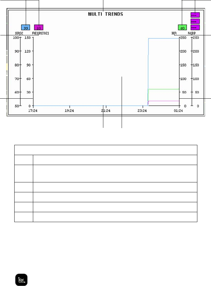
ExpressionMR200InstructionsforUseTrendDataandPrinting10‐3
Viewing Individual Trend Graphical Data
Toviewgraphicaltrenddataforasingleparameter
RotatethecontrolknobtohighlighttheVSboxofthedesiredparameterandthenpressthe
TRENDSkey.
Definition
1 Is the name of the graph
2 Are the numeric values of the selected parameters (y-axes) and
plotted in the same color
3 Are the selected parameters (y-axis labels)
4Is the y-axis plot
5Is the plot grid
6 Is the x-axis plot
1
3
6
2
4
5
2
3
4

10‐4TrendDataandPrinting ExpressionMR200InstructionsforUse
Viewing Multi Trend Graphical Data
Toviewgraphicaltrenddataformultipleparameters
Step Action
1PresstheTRENDSkey(whileinthenormalmode).
TheHISTORYmenuappearsandthefirstpageoftrenddataare
displayed.
2TurnthecontrolknobtoMULTITRENDSandthenpresstheknob.
TheMULTITRENDSsubmenuappears.
3TurnthecontrolknobtoSELECTandthenpresstheknobtochoose
theparametersusedintheplot.
4Turnthecontrolknobtoselectanyofthefollowingparameters
thenpresstheknobtoselecttheparameter.
HR
NiBP
SPO2
ETCO2
RESP[CO2]
Thiswillformthey‐axisoftheplot.
5Ifdesired,repeatstep4toselectadditionalparameters(uptofour
canbeplottedsimultaneously).Thenturnthecontrolknobto
RETURNandpresstheknob.
6TurnthecontrolknobtoTIMEBASEandthenpresstheknobtoset
thetimebaseusedfortheplot.
7Turnthecontrolknobtoselectoneofthefollowingintervalsand
thenpresstheknob.
20SEC
2HOURS
4HOURS
8HOURS
24HOURS
Thiswillbethex‐axisoftheplot.
8TurnthecontrolknobtoMENUBACKandthenpresstheknobto
positionthemenubehindthegraphforunobstructedviewing.
9TurnthecontrolknobtoCURSOR/ZOOMandthenpresstheknob
toexamineindividualpointsintime.
10 Whilethecursorisinthemostrightsideoftheplot,presstheknob
againtoexitthezoomfunction.
11 PresstheMainkeytoexitthemenu.

ExpressionMR200InstructionsforUseTrendDataandPrinting10‐5
HISTORY Menu
TheHISTORYmenuprovidesoptionstoselectpages.Upto48trend
recordscanbestored.Ahistoryfilecanbeviewedforallparameters.The
elementscontainedinthehistoryfilepagearedescribedbelow.
TochangesettingsintheHISTORYmenu
Step Action
1
PresstheTRENDSkey(whileinthenormalmode).
TheHISTORYmenuappears.Currentsettingsaredisplayed.
2Turnthecontrolknobtoselectanyofthefollowingoptionsand
thenpresstheknob:
PREVPAGE
NEXTPAGE
CLEARALL
MULTITRENDS
TRENDARROWS
ARROWPERIOD
Forinformationabouttheseoptions,seetheappropriatesections
below.
3Turntheknobtothedesiredsettingoritemandthenpressthe
knob.
4IfMULTITRENDSwasselected,gotostep5;otherwise,gotostep
7.
5Turnthecontrolknobtoselectanyofthefollowingoptionsand
thenpresstheknob:
SELECT
CURSOR/ZOOM
TIMEBASE
CLEARALL
TRENDARROWS
MENUBACK
Forinformationabouttheseoptions,seeMULTITRENDS,below.
6Turntheknobtothedesiredsettingoritemandthenpressthe
knob.

10‐6TrendDataandPrinting ExpressionMR200InstructionsforUse
PREV PAGE
Displaysthepreviouspageofthehistoryfile.
Todisplaythepreviouspageofthehistoryfile
SeeViewingMulti‐ParameterTabularTrendDataonpage10‐2fordetails.
NEXT PAGE
Displaysthenextpageofthehistoryfile.
Todisplaythenextpageofthehistoryfile
SeeViewingMulti‐ParameterTabularTrendDataonpage10‐2fordetails.
CLEAR ALL
Removesalltrenddata.Astrenddataisretainedwhena
newpatientisconnectedformonitoring,toavoidconfusion,
allpreviouslyacquireddatashouldbeclearedpriorto
connectionofanewpatient.
Beforedataerasure,adialogboxwillpromptyoufor
confirmation.Usethecontrolknobtohighlightthedesired
actionandthenpresstheknobtoproceed.
Toclearalltrenddata
PresstheTRENDSkey.TurnthecontrolknobtoCLEARALLandpresstheknob.
7PresstheMainkeytoclosethemenu.
Alternative:TurntheknobtoRETURNandthenpresstheknob,or
waitapproximately60seconds.
Step Action
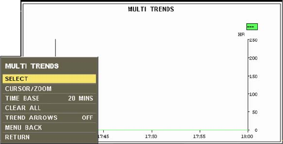
ExpressionMR200InstructionsforUseTrendDataandPrinting10‐7
MULTI TRENDS
Displaysagraphicalrepresentationofselectedmonitoredparameters.
Thefollowingchoicesareavailable:
•SELECTconfiguresuptofoursimultaneoustrendsusedtoplotthey‐axisofthegraph.
Thefollowingchoicesareavailable:
–HRplotsheartrate
–NiBPplotsNiBP
–SPO2plotsSPO2
–ETCO2
plotsEtCO2
–RESP[CO2]plotsCO2‐derivedrespiration
•CURSOR/ZOOMzoomsintothetrendchart,openingawindowwhereindividualpointsin
timecanbeviewed.(Toexitthisfeature,turnthecontrolknobuntiltheverticallineisas
fartotherightaspossibleandthenpresstheknob.)
•TIMEBASEconfigurestheintervalusedtoplotthex‐axisofthegraph.
Thefollowingchoicesareavailable:
–20SEC(Default)
–2HOURS
–4HOURS
–8HOURS
–24HOURS
•CLEARALLdeletesalldatafromthetrendhistory.
•MENUBACKmovesthemenubehindthegraphwindow.
TodisplaytheMultiTrendsgraphandsubmenu
PresstheTRENDSkey.TurnthecontrolknobtoMULTITRENDSandpresstheknob.
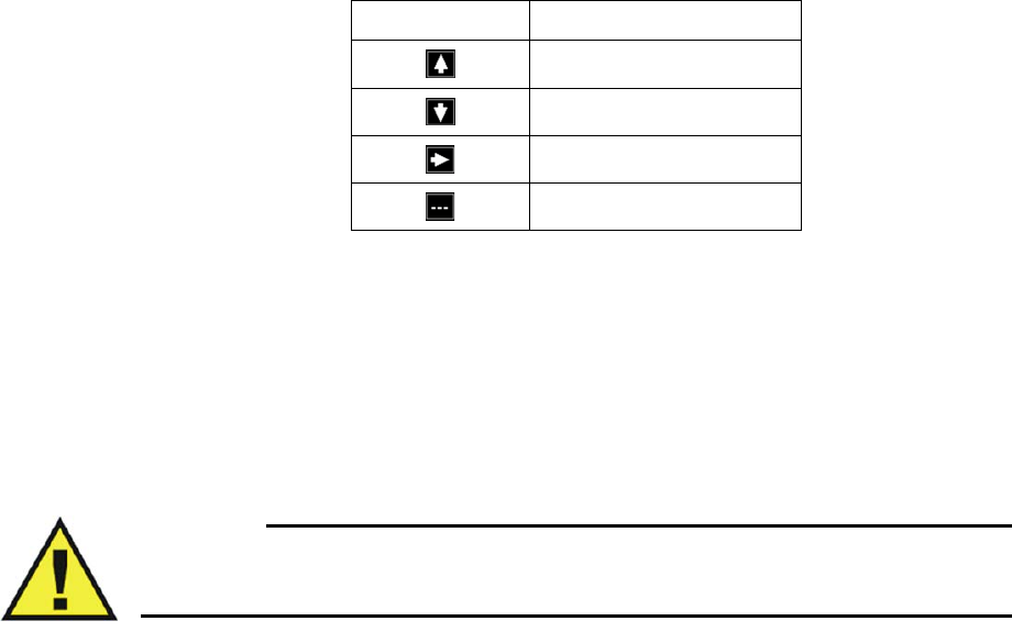
10‐8TrendDataandPrinting ExpressionMR200InstructionsforUse
TREND ARROWS
Controlsavitalsigntrendindication,whereatrendarrowisdisplayedalongsidetheVSbox(not
availableforbellows‐derivedrespiration)withameaningasdefinedinthetablebelow.(See
page2‐14foranexample.)
Thefollowingchoicesareavailable:
•ONturnsonthetrendarrows.
•OFFturnsoffthetrendarrows.(Default)
Todisplaytrendarrows
PresstheTRENDSkey.TurnthecontrolknobtoTRENDARROWSandpresstheknob.Thenturn
thecontrolknobtoON.
WARNING
Depending upon the ARROW PERIOD and measurement cycles of the vital signs, NiBP
trend arrow indications may not be representative of the current condition of the patient.
ARROW PERIOD
Setsthetimeusedtocalculateanddeclarethedirectionforthetrendarrows.
Thefollowingchoicesareavailable:
•30SEC
•1MIN
•3MIN(Default)
•5MIN
•10MIN
Tosetthearrowperiod
PresstheTRENDSkey.TurnthecontrolknobtoARROWPERIODandpresstheknob.Thenturn
thecontrolknobtothedesiredinterval.
Indication Meaning
Rising
Declining
Stable
None declared

ExpressionMR200InstructionsforUseTrendDataandPrinting10‐9
NOTE
If a newly selected period is shorter than the previous period (and the arrows have been on for the
longer of the two periods) then immediate recalculation using the new period will occur.
Alternately, if the newly selected period is longer than the previous period, recalculation will occur
using all available data.
Print Functions
WhenequippedwithanIP5printer,theMR200canprovidesingleordualwaveformstripcharts.
NOTES
• If a printer-equipped IP5 is not installed or connected to the system, will be displayed
in the communication and power status display area on the LCD. For a listing of printer
icons, see page 2-16.
• Any print command from the MR200 automatically initiates a 30-second print cycle at the
IP5.
• Any print command initiated from the MR200 takes precedence over the IP5 print functions.
PRINTER Menu
ThePRINTERSETUPoption(intheSETUPmenu)opensthePRINTERmenu,whichcontains
optionsforprintersetupandcontrolwhentheMR200isequippedwithanoptionalIP5and
printer.Forexpandedprintingoptionsnotcoveredinthismanual,consulttheIP5IFU.
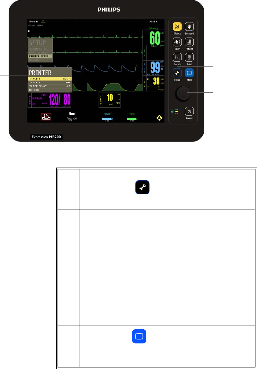
10‐10TrendDataandPrinting ExpressionMR200InstructionsforUse
.
TochangesettingsinthePRINTERmenu
Setup key
Control knob
PRINTER
menu
Step Action
1PresstheSETUPkey.
TheSETUPmenuappears.
2
TurnthecontrolknobtoPRINTERSETUPandthenpresstheknob.
ThePRINTERmenuappears.Currentsettingsaredisplayed.
3Turnthecontrolknobtoselectanyofthefollowingprinteroptions
andthenpresstheknob:
TRACE1
TRACE2
TRACEDELAY
Forinformation,seetheappropriatesectionsbelow.
4Turntheknobtothedesiredsettingandthenpresstheknob.
5Tochangeotheroptions,repeatsteps3and4.
6PresstheMainkeytoclosethemenu.
Alternative:TurntheknobtoRETURNandthenpresstheknob,or
waitapproximately60seconds.
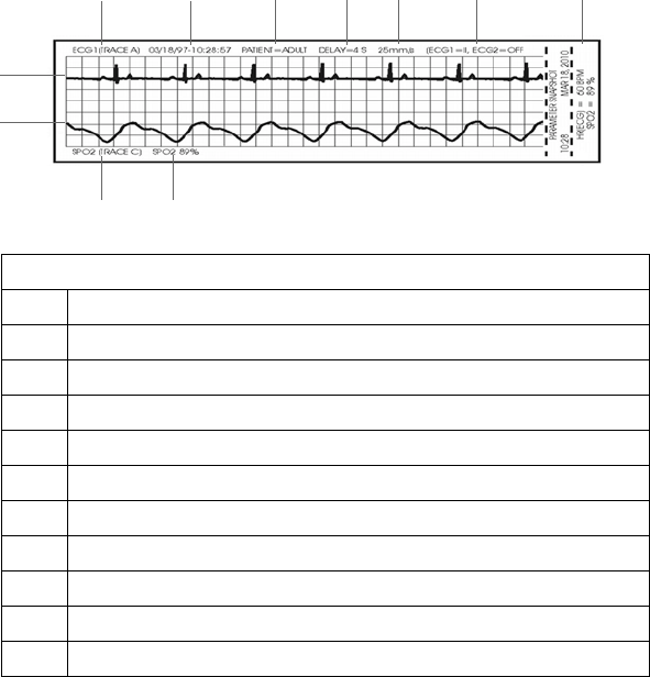
ExpressionMR200InstructionsforUseTrendDataandPrinting10‐11
TRACE 1
Enablesthefirsttracetobeoutputbytheprinter.Thestripchartmaybeconfiguredtocontain
oneortwowaveforms(seeTRACE2,below).Adescriptionofeachitemprintedonthestripchart
isprovidedbelow.
Thefollowingchoicesareavailable:
•ECG1(TraceA)(Default)
•ECG2(TraceB)
•SPO2(TraceC)
•RESP(CO2)(TraceD)
ToprintaTrace1waveform
EnterthePRINTERmenu.PressthecontrolknobtoselectTRACE1andpresstheknob.Scrollto
thedesiredoutputandpresstheknob.
Definition
1 Trace 1 parameter
2 Date and time (formatted as MM/DD/YY-HH:MM:SS)
3 Patient type
4Trace delay
5 Trace speed
6 Parameter information
7 Values of active parameters at time of printing
8 Trace 2 parameter information
9 Trace 2 parameter
10 Trace 2 waveform
11 Trace 1 waveform
1234567
8
9
11
10

10‐12TrendDataandPrinting ExpressionMR200InstructionsforUse
TRACE 2
Enablesthesecondtracetobeoutputbytheprinter.
Thefollowingchoicesareavailable:
•OFF(Default)
•ECG1outputstheTraceAwaveform.(Default)
•ECG2outputstheTraceBwaveform.
•SPO2outputstheTraceCwaveform.
•RESP(CO2)outputstheTraceDwaveform.
ToprintaTrace2waveform
EnterthePRINTERmenu.TurnthecontrolknobtoTRACE2andpresstheknob.Scrolltothe
desiredoutputandpresstheknob.
NOTE
If TRACE 2 is Off, a single trace is printed using the full 40 mm width of the strip chart. When
printing two traces, the waveform to grid ratio will not correspond to the waveform/scale
indicator size displayed on the LCD.
TRACE DELAY
Setsadelayperiodfortheprintedtrace.
Thefollowingchoices(inseconds)areavailable:
•0(Default)
•4
•8
•16
Tosetaprintingtimedelay
EnterthePRINTERmenu.TurnthecontrolknobtoTIMEDELAYandpresstheknob.Scrolltothe
desiredsettingandpresstheknob.

ExpressionMR200InstructionsforUseCleaningandMaintenance11‐1
CHAPTER 11
Cleaning and Maintenance
Environmental Requirements
RoyalPhilipsHealthcareisconcernedaboutprotectingthenaturalenvironmentandtohelp
ensurecontinuedsafeandeffectiveuseofthisproductthroughpropersupport,maintenance
andtraining.RoyalPhilipsequipmentisthereforedesignedandmanufacturedtocomplywith
relevantguidelinesforenvironmentalprotection.Aslongastheequipmentisproperlyoperated
andmaintained,itpresentsnorisktotheenvironment.However,theequipmentmaycontain
materialswhichcouldbeharmfultotheenvironmentifdisposedofincorrectly.Useofsuch
materialsisessentialfortheimplementationofcertainfunctionsandformeetingcertain
statutoryandotherrequirements.
ThissectionoftheInstructionsforUseisdirectedmainlyattheuseroftheequipmentorsystem,
thebodywithlegalauthorityovertheequipment.Operatorsarenotusuallyinvolvedindisposal,
exceptinthecaseofcertainbatteries,seepage11‐7.
General Cleaning Guidelines
KeeptheMR200andaccessoriesfreeofdust,dirtandpathogens.Aftercleaninganddisinfection,
alwayschecktheequipmentcarefully.Stopusingequipmentthatshowssignsofdeteriorationor
damage.Observethefollowinggeneralprecautionswhencleaning:
•Alwaysdilutethecleaningsubstanceaccordingtothemanufacturer’sinstructionsoruse
lowestpossibleconcentration.
• Neverallowliquidtoentertheequipment.
• Neverimmerseanypartoftheequipmentinliquid.
• Neverpourliquidontotheequipment.
• Neveruseabrasivematerialtowipetheequipment.
NOTE
For answers to questions regarding infection control:
• Users inside USA, call us at (877) 468-4861
• Users outside USA, call us at +31 (0) 499 378299

11‐2CleaningandMaintenanceExpressionMR200InstructionsforUse
Cleanusingalint‐freecloth,moistenedwithwarmwater(40°C/104°Fmaximum)andmildsoap,
adilutednon‐causticdetergentoralcohol‐basedcleaningagent.Neverusestrongsolventssuch
asacetoneortrichloroethylene.Stainscanberemovedbyscrubbingbrisklywithamoistened
cloth.Ifdisinfectionisrequired,cleantheequipmentbeforedisinfectingit.
UseonlytheRoyalPhilips‐approvedsubstancesandmethodslistedinthischaptertocleanor
disinfecttheequipment.RoyalPhilipsmakesnoclaimsregardingtheefficacyofthelisted
chemicalsormethodsasameansforcontrollinginfection.Warrantydoesnotcoverdamage
causedbyusingunapprovedsubstancesormethods.
Therecommendedtypesofdisinfectingagentsarelistedinthetablebelow.Wemakenoclaims
regardingtheefficacyofthelistedchemicalsormethodsasameansforcontrollinginfection.
Consultyourfacility'sInfectionControlOfficerorEpidemiologist.Forcomprehensivedetailson
cleaningagentsandtheirefficacyreferto“GuidelinesforPreventionofTransmissionofHuman
ImmunodeficiencyVirusandHepatitisBVirustoHealthCareandPublic‐SafetyWorkers”issued
bytheU.S.DepartmentofHealthandHumanServices,PublicHealthService,CentersforDisease
Control,February1989.Alsorefertoanypoliciesthatapplywithinyourfacilityandcountry.
*Followmanufacturer'sinstructionsformixing;werecommendasolutionof5,000ppm.
**Anyproductresidueshouldberemovedbywiping.
Cleaning the Cart and Modules
WARNING
Always disconnect the MR200 from AC power, and remove the batteries from the cart and
the wireless modules, before performing any cleaning or maintenance. To avoid an electrical
hazard, never immerse any part of the MR200 in any cleaning agent or attempt to clean it
with liquid cleaning agents.
FollowthegeneralguidelinestocleanthecartandthewECGandwSPO2modules.Alwaysturn
offthecartandthemodulestoperformcleaning.Neverimmerseportionofthecartorthe
modulesinfluidorattempttocleanthedevicesbydirectlyapplyingliquidcleaningagents.
Product Name Product Type
Actichlor™ Plus Tablet*
CaviWipes® Disinfectant Towelette
Coverage® Spray TB, TB Plus, HB Plus** Spray
Sklar Disinfectant** Towelette
Sani-Cloth Plus Wipes** Towelette

ExpressionMR200InstructionsforUseCleaningandMaintenance11‐3
CAUTIONS
• Other than those specified in the preceding table, avoid ammonia-, phenol- and acetone-
based cleaners as they will damage the surfaces of the MR200.
• Disinfect the cart and modules as determined by your hospital’s policy to avoid long term
damage to the product.
• Do not permit liquid to contact the front or rear of the display panel. Do not permit liquid to
drip into or around the LCD. Contact technical support if liquid enters any component.
• If the MR200 becomes accidentally wet during use, discontinue operation until all affected
components have been cleaned and permitted to completely dry. Contact technical support if
additional information is required.
Tocleananddisinfectthecartandwirelessmodules
Step Action
1TurnoffthecartandunplugtheACpowercord.Removethe
batteries,ifinstalled.
2 Removethebatteryfromeachwirelessmodule.
3 Removeallvisibledebrisfromthecartandwirelessmodulesusing
soapandwater.
CAUTIONS
Never pour liquid onto the equipment.
4Cleanthecartandmodulesbythoroughlywipingthedevicesusing
CaviWipesDisinfectanttowelettes.Discardtheusedtowelettes
(refertoyourfacility'sbiohazardprocedurefordisposal).
NOTE
Follow the instructions for use from the disinfectant manufacturer to
clean the cart and modules.
5 Disinfectthecartandmodulesbythoroughlywettingthedevices
usingCaviWipesDisinfectanttowelettes.Discardtheused
towelettes(refertoyourfacility'sbiohazardprocedurefor
disposal).
NOTE
Follow the instructions for use from the disinfectant manufacturer to
disinfect the cart and modules.
11‐4CleaningandMaintenanceExpressionMR200InstructionsforUse
Sterilizing the Cart and Wireless Modules
Thecartandthemodulesarenotsterilizable;donotimmerseanypartofthesedevicesinfluidor
attempttocleanthemwithliquidcleaningagents.Severedamage,notcoveredbythewarranty,
willresult.
Cleaning the Accessories
Anyreusablepatientaccessory(suchasSPO2attachmentsandsensors,ECGcables,NiBPcuffs,
chestbellows,etc.)mustbecleanedanddisinfectedbeforeinitialuse,andthenaftereachuse,to
protectpatientsandpersonnelfromavarietyofpathogens.Usesoapandwater,andasuggested
disinfectantandmethod,tocleananddisinfecttheaccessories.Thewarrantydoesnotcover
damagecausedbyunapprovedsubstancesormethods.
Disposableaccessoriesmustbediscardedandreplacedwithnewitems.
WARNING
Single-use devices, as indicated on the device packaging, should be disposed of
after use and must never be reused.Reuse of single-use devices can result in
spread of patient infection, degradation of monitoring performance, or
inaccurate measurements.
CAUTIONS
• Never immerse an accessory in any cleaning fluid.
• Do not autoclave any part of the equipment. Disinfect the accessory as determined by your
facility’s policy.
NOTE
Disposable SPO2 attachments: After some use, adhesive residue may accumulate at the fiber heads
on the sensor cable. Remove carefully any residue with some alcohol. The glass fiber ends must
always be clear and free from residuals.
6Allowthecartandthemodulestodry.(Norinsingisrequired.)
7Checkthecartandthemodulesforanyresidualdebris.Ifanydebris
ispresent,repeatsteps3through6thenre‐examinethecartand
modulesbeforeproceeding.
8Checkthecartandmodulesfordamageandcontacttechnical
supportifdamageisfound.
Step Action

ExpressionMR200InstructionsforUseCleaningandMaintenance11‐5
Tocleanareusableaccessory
Sterilizing the Accessories
Theaccessoriesarenotsterilizable.Severedamage,notcoveredbythewarranty,willresult.
Step Action
1 Removetheaccessoryfromuse.
2 Removeallvisibledebrisfromtheaccessoryusingsoapandwater.
CAUTION
Never pour liquid onto the accessory.
3CleantheaccessorybythoroughlywipingitusingCaviWipes
Disinfectanttowelettes.Discardtheusedtowelettes(refertoyour
facility'sbiohazardprocedurefordisposal).
NOTE
Follow the instructions for use from the disinfectant manufacturer to
clean the sensor.
4 DisinfecttheaccessorybythoroughlywettingitusingCaviWipes
Disinfectanttowelettes.Discardtheusedtowelettes(refertoyour
facility'sbiohazardprocedurefordisposal).
NOTE
Follow the instructions for use from the disinfectant manufacturer to
disinfect the sensor.
5Allowtheaccessorytodry.(Norinsingisrequired.)
6Checktheaccessoryforanyresidualdebris.Ifanydebrisispresent,
repeatsteps2through5thenre‐examinethesensorbefore
proceeding.
7Checktheaccessoryfordamageanddiscardtheaccessoryif
damageisfound;seepage11‐6fordetails.
8Storetheaccessory;seepage11‐6fordetails.
9Inspecttheaccessoryforanycracks,holes,tears,cuts,etc.that
couldaffectoperationandreplaceasnecessary.

11‐6CleaningandMaintenanceExpressionMR200InstructionsforUse
Inspecting the Accessories for Damage
Theaccessoriesareexposedtopotentiallydamagingsituationsduringuseandcleaning.Before
eachuse,carefullyinspecttheaccessoriesforthefollowingsignsofdamage:
•Cracks,holes,tears,gouges,cuts,etc.
•Cracksorothersignsofdamagetotheconnector,includingbentordamagedpins.
WARNING
Cracks, tears, cuts and gouges interfere with standard cleaning procedures and therefore
pose a potential risk to patients and personnel. If you see any sign of damage to any
accessory, immediately discontinue use.
Storing the Accessories
Thecarthasbuilt‐instoragefeaturestohousewirelessmodulesandaccessoriesusedduring
monitoring;seepage2‐3.
WARNING
To reduce the spread of infection, do not store accessories directly on the MR200 handles.
CAUTION
When inserting or removing the accessories from the cart or wireless modules, only use the
connector and never pull or apply excessive force or tension to any other portion of the device.
Tostorethewirelessmodulesandsensorsandcables
Whennotinuse,slidethewECGandwSPO2modulesintothemoduleholdersonthecart.
Tostoretheotheraccessories
Whennotinuse,loopsamplelinesandthenplacetheminthestoragebasketordrapethem
overanoptionalaccessoryhook.
Final Disposal
Finaldisposaliswhentheuserdisposesoftheequipment(system,accessoriesandbatteries)in
suchawaythatitcannolongerbeusedforitsintendedpurposes.
ExpressionMR200InstructionsforUseCleaningandMaintenance11‐7
WARNING
Do not dispose of this product (or any parts of it) in industrial or domestic waste.
The system may contain materials and hazardous substances that can cause
serious environmental pollution. The system also contains privacy sensitive
information. It is advisable to contact your Royal Philips Service Organization
before disposing of this product.
RoyalPhilipsHealthcaregivessupportfor:
• Recoveryofreusableparts.
•Therecyclingofusefulmaterialsbycompetentdisposalcompanies.
•Safeandeffectivedisposalofequipment.
Fordetaileddisposalinformation,gotothefollowingwebpage:
http://www.healthcare.philips.com/main/about/sustainability/recycling/pm.wpd
Therecyclingpassportslocatedtherecontaininformationonthematerialcontentofthe
equipment,includingpotentiallydangerousmaterialswhichmustberemovedbeforerecycling
(forexample,batteries).
Disposal of the Device and Accessories
TheMR200andaccessoriesaresubjecttostrictdisposalregulationsforuserandenvironmental
safety.Neverdisposeofwasteelectricalandelectronicequipmentasunsortedmunicipalwaste.
Collectitseparatelysothatitcanbesafelyandproperlyreused,treated,recycledorrecovered.
WARNING
To avoid contaminating or infecting personnel, the environment or other equipment, make
sure you disinfect and decontaminate the MR200 appropriately before disposing of it in
accordance with your country's laws for equipment containing electrical and electronic
parts. Do not dispose of this product (or any parts of it) in industrial or domestic waste. The
system may contain materials such as lead, tungsten or oil, or other hazardous substances
that can cause serious environmental pollution. The system also contains privacy sensitive
information. It is advisable to contact your Royal Philips Service Organization before
disposing of this product. You can disassemble the MR200 and accessories as described in
the service manual.
Disposing of Batteries
Thelithiumbatteriesfoundinthesystemandsomeoftheaccessoriesoroptionalequipment
maybesubjecttostrictdisposalregulationsforuserandenvironmentalsafety.Observeand
adheretoyourcurrentlocalregulationswhendisposingofbatteries.

11‐8CleaningandMaintenanceExpressionMR200InstructionsforUse
CAUTIONS
• Never heat or throw a battery into fire. Heating the battery will damage the safety circuitry,
which can cause rupture or ignition of the battery.
• Never disassemble a battery. The batteries contain hazardous material that must be recycled
or disposed of properly. (Refer to the disposal guidelines below.)
Maintenance
PeriodicmaintenancefortheMR200,asoutlinedbelow,mustbefollowed.
CAUTION
Annual preventative maintenance is recommended unless stated otherwise in the service manual.
For proper equipment maintenance, perform the service procedures at the recommended intervals
as described in the service manual.
Testing CO2 Accuracy
TheCO2flowrateaccuracyshouldbeverifiedbydirectmeasurementusingacalibratedflow
meterevery12months.(SeeGASCALonpage11‐14.)
CAUTION
An internal leak may result in condensation within the system. If this is suspected or if
condensation is observed, discontinue use and contact technical support.
Testing the NiBP System
TheNiBPsystemshouldbetestedatleastonceevery12monthstoensureproperoperation.
WARNING
Never initiate the LEAK TEST while the cuff is applied to a patient. Continuous cuff
pressure can lead to patient injury.
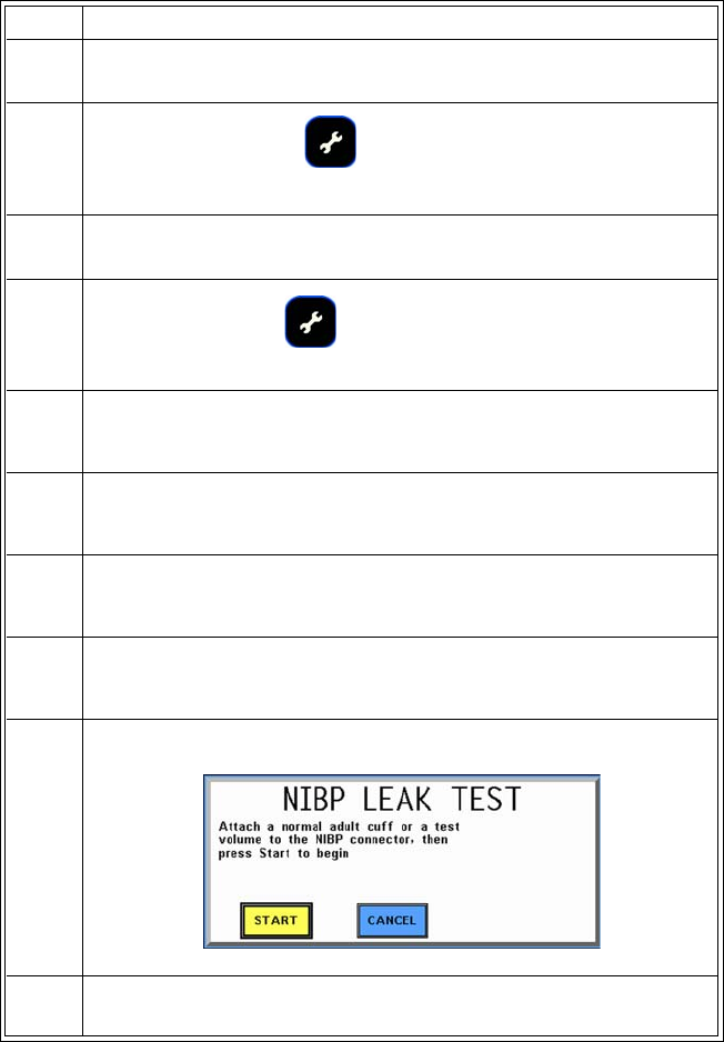
ExpressionMR200InstructionsforUseCleaningandMaintenance11‐9
TotesttheNiBPsystemforleakage
Step Action
1 Attachanormaladultcuffandinterconnecthose,oratestvolume
totheMR200.
2
PressthePATIENTkey.
ThePATIENTmenuappears.
3TurnthecontrolknobtoADULT(orPEDIATRIC)andthenpressthe
knob.
4PresstheSETUPkey.
TheSETUPmenuappears.
5TurnthecontrolknobtoMONITORSETUPandthenpresstheknob.
TheMONITORmenuappears.Currentsettingsaredisplayed.
6TurnthecontrolknobtoSERVICE(BIO‐MED)andpresstheknob.
TheSERVICE(BIO‐MED)menuappears.
7TurnthecontrolknobtoNiBPTESTSandpresstheknob.
TheNiBPTESTSmenuappears.
8TurnthecontrolknobtoLEAKTESTandthenpresstheknob.
TheNiBPLEAKTESTdialogboxappears.
9Turntheknobtothedesiredactionandthenpresstoproceed.
10 ResultsareprovidedontheLCDastheroutineprogressesthrough
thedifferenttests.
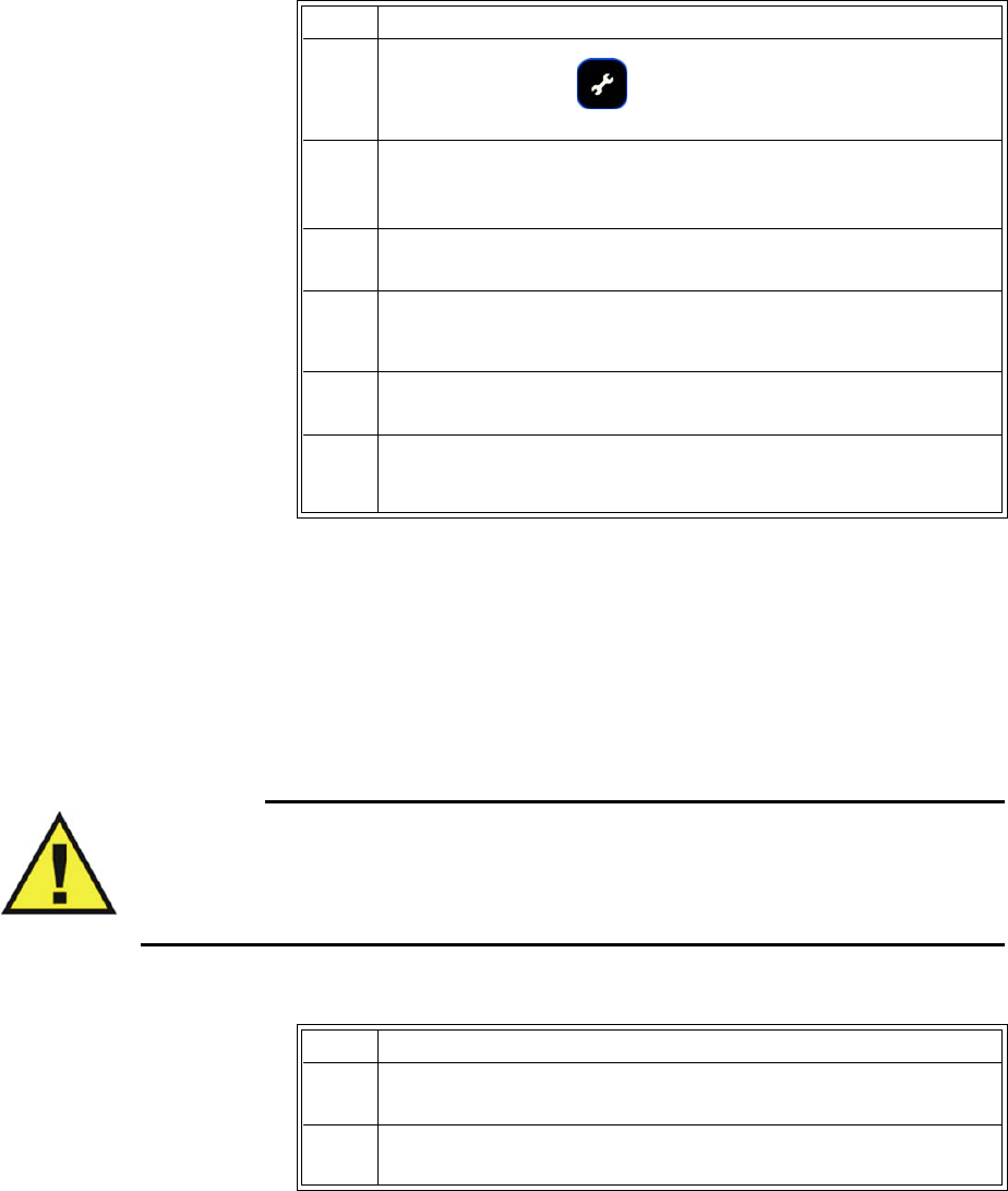
11‐10CleaningandMaintenanceExpressionMR200InstructionsforUse
Default Initialization
ThesettingsfortheMR200canberestoredtofactorydefaultvalues.
Updating Software
Asrevisionstothesoftwarebecomeavailable,theMR200canbeupdated.Itisrecommended
thatyousaveyoursettingspriortoupdatingsoftware,sothattheycanberestoredafterward;
seeSTORESETUPSonpage3‐5.
WARNING
When performing software updates (or upgrades) to the operating software of the MR200,
ensure that all remaining devices in the monitor’s network are at the same or a compatible
software revision level. Failure to observe this requirement could result in compatibility
conflicts, communication problems, etc.
Toupdatetheoperatingsoftware
Step Action
1PresstheSETUPkey.
TheSETUPmenuappears.
2TurnthecontrolknobtoMONITORSETUPandthenpresstheknob.
TheMONITORmenuappears.Currentsettingsaredisplayed.
3TurnthecontrolknobtoDEFAULTSETUPSandpresstheknob.
4ScrolltoFACTORYandpresstheknob.
Allcurrentsettingswillbelost.
5TurnofftheMR200.
6TurnontheMR200.
Themonitor’ssettingsarereturnedtothefactorydefaultvalues.
Step Action
1ConnectACpowertothecartandinsertatleastonefullycharged
battery.
2Turnonthecartthenwaituntilthenormalmodeisdisplayed;see
LCDonpage2‐13.
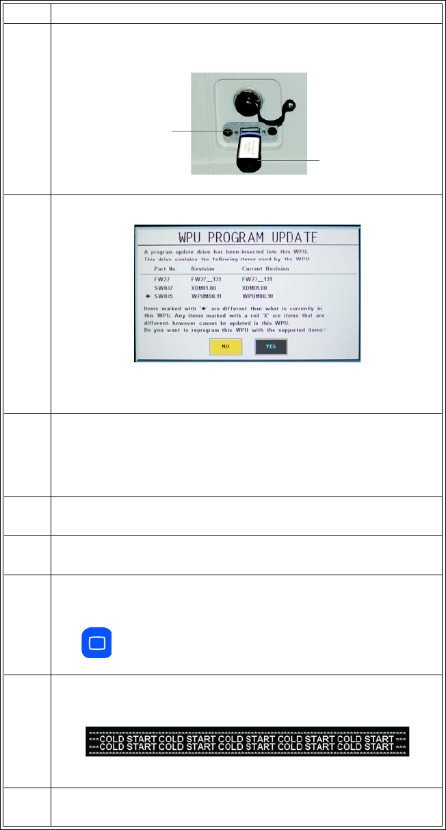
ExpressionMR200InstructionsforUseCleaningandMaintenance11‐11
3InserttheUSBprogramupdatedevicethatcontainsthedesired
softwareintotheUSBport.
4TheWPUProgramUpdatewindowappears.
Currentsoftwarerevisionsaredisplayed,whereanyneededupdate
willbedenotedbyanasterisk.
5TurnthecontrolknobtoYESandthenpresstheknobtoproceed.
Thesoftwareupdatebegins.Aprogressbarisdisplayedandwhen
allapplicableprogramupdateshavefinished,theWPUProgram
Updatewindowchangestoindicatecompletion.
6TurnoffthecartandremovetheUSBprogramupdatedevicefrom
theUSBport.
7Pressandholdthecontrolknobwhileturningonpowertothecart.
8ObservetheLCD.Whenthecursormovestotheupperleftcorner
ofthescreen(approximately10–15secondsafterpower‐up),
releasethecontrolknobthenimmediatelypressandholdtheMain
key.
9Whenthecoldstartbannerismomentarilydisplayed,releasethe
Mainkey
.
TheMR200willboottothenormalmode.
10 Ifthecoldstartbannerwasnotdisplayed,repeatsteps7–9.
Step Action
USB port
USB program
update device
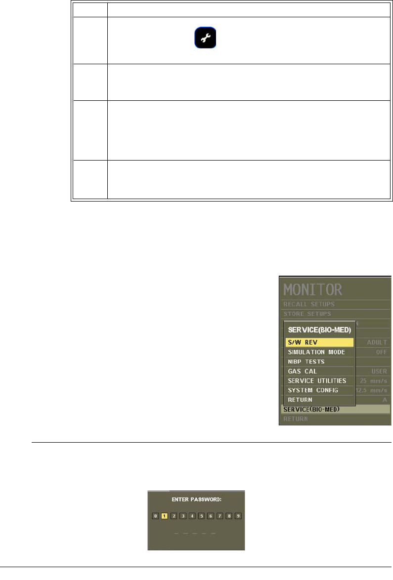
11‐12CleaningandMaintenanceExpressionMR200InstructionsforUse
SERVICE(BIO-MED) Menu
TheSERVICE(BIO‐MED)menucontainssoftwareandfirmware
informationaboutthesystemandoptionsforpressure,diagnostics
andconfiguration.
NOTE
Some SERVICE(BIO-MED) menu options require entry of a password for access. For password
assistance, contact technical support. For details regarding these password-protected options,
reference the service manual.
11 PresstheSetupkey.
TheSETUPmenuappears.
12 TurnthecontrolknobtoMONITORSETUPandthenpresstheknob.
TheMONITORmenuappears.Currentsettingsaredisplayed.
13 TurnthecontrolknobtoSERVICE(BIO‐MED)andthenpressthe
knob.
TheSERVICE(BIO‐MED)menuappears.Currentsettingsare
displayed.
14 WithS/WREVhighlighted,pressthecontrolknob.Verifythatthe
displayedREVISIONINFORMATIONincludestheversionnumberfor
thesoftwarethatwasupdated.
Step Action
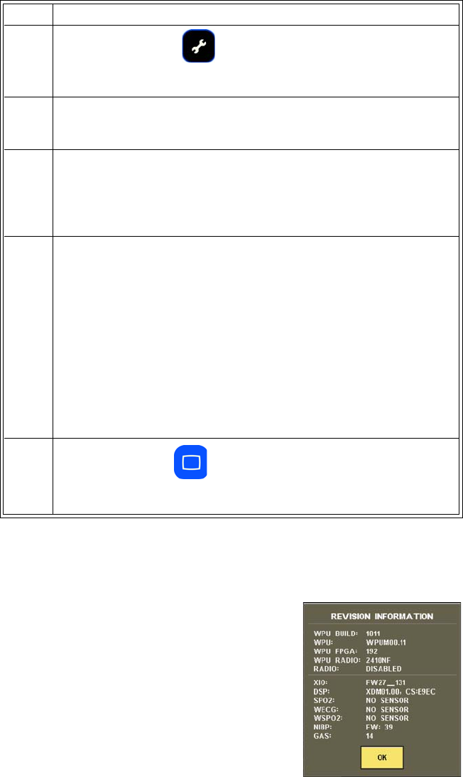
ExpressionMR200InstructionsforUseCleaningandMaintenance11‐13
ToentertheSERVICE(BIO‐MED)menu
S/W REV
Opensawindowthatcontainsrevisionlevelandbuilddate
informationforthesoftwarecomponents.(Toclosethewindow,
pressthecontrolknoborwait60seconds.)
SIMULATION MODE
Step Action
1PresstheSETUPkey.
TheSETUPmenuappears.
2TurnthecontrolknobtoMONITORSETUPandthenpresstheknob.
TheMONITORmenuappears.Currentsettingsaredisplayed.
3TurnthecontrolknobtoSERVICE(BIO‐MED)andthenpressthe
knob.
TheSERVICE(BIO‐MED)menuappears.Currentsettingsare
displayed.
4Turnthecontrolknobtoselectanyofthefollowingoptionsand
thenpresstheknob:
S/WREV
SIMULATIONMODE
NiBPTESTS
GASCAL
SERVICEUTILITIES
SYSTEMCONFIG
Forinformationabouttheseoptions,seetheappropriatesections
below.
5PresstheMainkeytoclosethemenu.
Alternative:TurntheknobtoRETURNandthenpresstheknob.
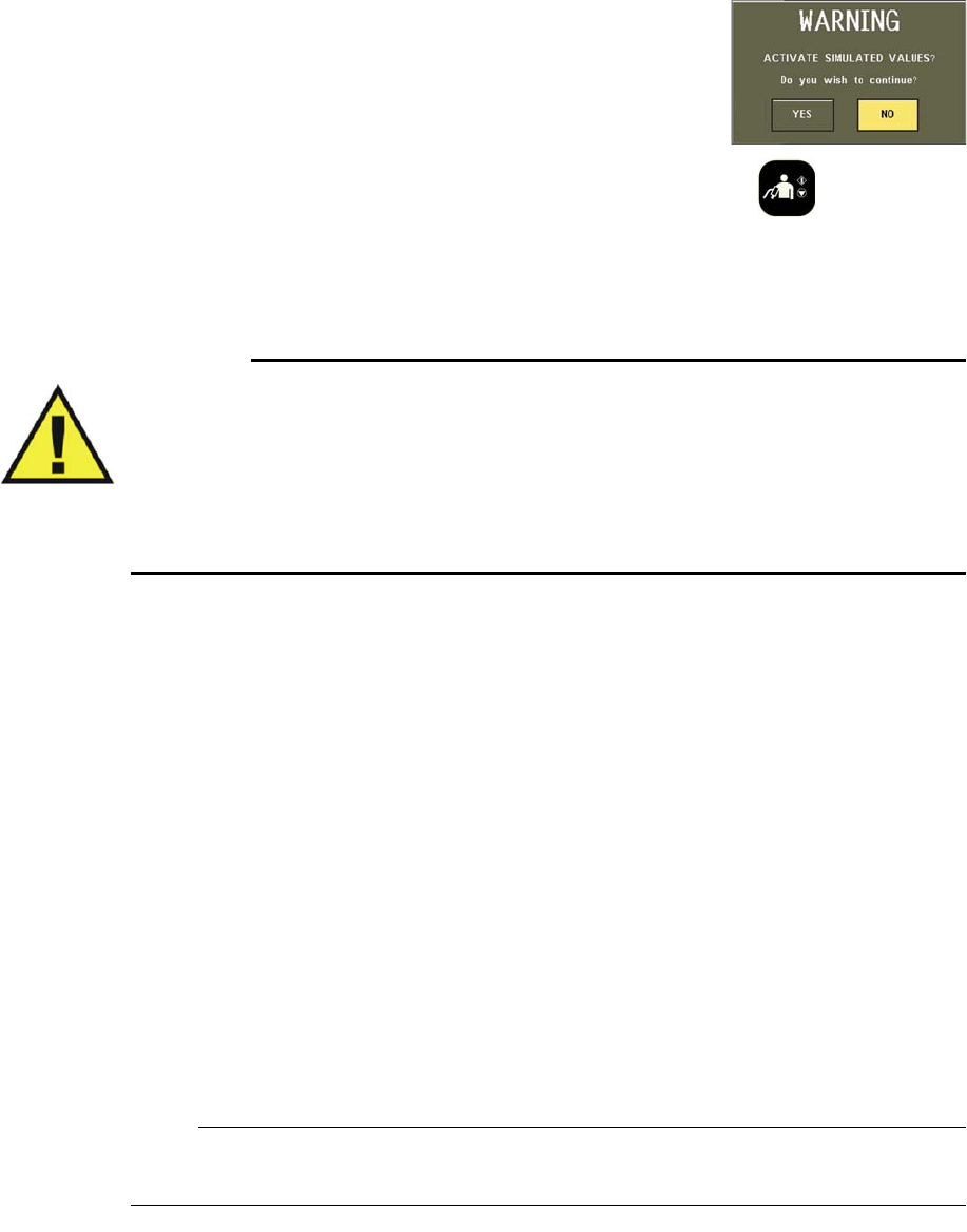
11‐14CleaningandMaintenanceExpressionMR200InstructionsforUse
PlacestheMR200intosimulationmode.
Toentersimulationmode
Pressthecontrolknob.Adialogboxwillpromptyoufor
confirmation.Usethecontrolknobtohighlightthedesiredaction
andthenpresstheknobtoproceed.
Whileinsimulationmode,toinitiatesimulatedNiBPfunctions,presstheNiBPkey.
Toexitsimulationmode
Turnoffthepowerswitch.
WARNING
The MR200 is equipped with a simulation mode that displays computer generated data for
training or demonstration. As a safety feature, SIMULATION is displayed and appears on
all printouts while in simulation mode. Do not attach a patient to the MR200 when in
simulation mode and never activate simulation mode when a patient is connected. The
MR200 will not monitor patients while in the simulation mode. Activating simulation mode
when a patient is connected will result in a lapse in patient monitoring and could result in a
delay in treatment.
NiBP TESTS
AccessesNiBPcalibrationandtestingfunctions.
•CALIBRATEperformscalibrationoftheNiBPsystem.(Passwordrequired)
•LEAKTESTteststheNiBPsystemforpressureleaks.
Toperformtheleaktest
Seepage11‐8.
•STATICTESTteststhepressureoftheNiBPsystem.(Passwordrequired)
GAS CAL
AccessestheCO2calibrationandtestingfunctions.
NOTE
Wait 2 minutes for CO2 warm-up before calibrating or performing an accuracy check.
Thefollowingchoicesareavailable:

ExpressionMR200InstructionsforUseCleaningandMaintenance11‐15
•ZEROCALperformsazerocalibrationoftheCO2system.(Alsoseepage7‐11.)
Tostartzerocalibration
EntertheSERVICE(BIO‐MED)menu.TurnthecontrolknobtoGASCALandpresstheknob.
ScrolltoZEROCALandpresstheknob.
•CO2ACCURACYCHECKteststheCO2
function(a5%sourcemustbeconnected).
ProvidesaCO2waveformvalue(asa
percentage),anatmosphericpressure
readingandanumericCO2value(in
mmHg).
Toperformanaccuracycheck
Connectthe5%CO2sourcetotheCO2port.EntertheSERVICE(BIO‐MED)menuandscroll
toGASCAL.PressthecontrolknobthenscrolltoCO2ACCURACYCHECKandpressthe
knobagain.(Awarningdialogwillappear:CO2BENCHSHOULDBEWARMEDUPPRIORTO
STARTINGACCURACYTEST.Pressthecontrolknobwhenreadytoproceed.)
NOTE
During the accuracy check, to alert you that the indicated values are not actual patient numerics,
the following dialog box message will be displayed: CO2 test in progress. Do not use CO2 values
for patient monitoring during test. Pressing close will cancel test.
SERVICE UTILITIES
Accessesservice‐relatedfunctions(passwordrequired);seetheservicemanualfordetails.
SYSTEM CONFIG
ConfigurestheparametersandoptionsoftheMR200.(Forpasswordprotectedfunctions,see
theservicemanualfordetails.)
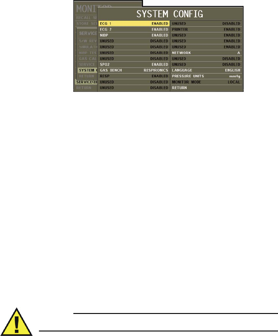
11‐16CleaningandMaintenanceExpressionMR200InstructionsforUse
•LANGUAGEsetsthelanguagedisplayedbytheMR200(tomaketheselectioneffective,
cyclepoweraftersavingyourchanges):
–ENGLISH(Default)
–DEUTSCH
–ESPANOL
–FRANCAIS
–PORTUGUES(Br)
–ITALIANO
–DANSK
–SVENSKA
–NORSK
–NLD
•PRESSUREUNITSsetstheunitofmeasureforNiBPreadings:
–mmHgprovidesreadingsinmillimetersofmercury.(Default)
–kPaprovidesreadingsinkilopascals
Repair
TheMR200containsnouser‐serviceableparts.Allrepairsmustbeperformedbytrainedservice
personnel.Allrepairsonproductsunderwarrantymustbeperformedbyauthorizedpersonnel
orinanauthorizedServiceandRepairCenter.Unauthorizedrepairswillvoidthewarranty.
WARNING
A shock hazard exists if the MR200 is operated without covers.

ExpressionMR200InstructionsforUseCleaningandMaintenance11‐17
IftheMR200failstofunctionproperlyorrequiresmaintenance,contacttechnicalsupport:
1‐877‐INVIVO1
or
1‐877‐468‐4861
Internationally,pleasecontactyourKeyMarketrepresentative.Foracurrentlisting,goto
www.invivocorp.com
CAUTIONS
• This product, or any of its parts, must not be repaired other than in accordance with written
instructions provided by Invivo (Royal Philips), or altered without prior written approval.
• No repair should ever be undertaken or attempted by anyone not having a thorough
knowledge of the repair of Invivo (Royal Philips) patient monitoring systems. Only replace
damaged parts with components manufactured or sold by Invivo (Royal Philips). Contact
the Technical Service and Repair Center for assistance and service.
CAUTION
The user of this product shall have the sole responsibility for any malfunction which results from
improper use, faulty maintenance, improper repair, damage, or alteration by anyone other than
Invivo (Royal Philips) or its authorized service personnel.
Passing This Product on to Another User
Ifthisproductistobepassedontoanotheruserwhoistouseitforitsintendedpurpose,thenit
shouldbepassedoninitscompletestate.Inparticular,theexistingusershouldmakesurethatall
theproductsupportdocumentation—includingallInstructionsforUse—arepassedontothenew
user.AnewusershouldbemadeawareofthesupportservicesthatRoyalPhilipsHealthcare
providesforinstalling,commissioningandmaintainingtheequipmentorsystem,andforthe
comprehensivetrainingofoperators.Existingusersmustbearinmindthatpassingonmedical
electricalequipmenttonewusersmaypresentserioustechnical,medical,privacyandlegalrisks.
Theoriginalusermayremainliableeveniftheequipmentisgivenaway.
ExistingusersarestronglyadvisedtoseekadvicefromtheirlocalRoyalPhilipsHealthcare
representativebeforeagreeingtopassonanyequipment.
Oncetheequipmenthasbeenpassedontoanewuser,theprevioususermaystillreceive
importantsafety‐relatedinformation,suchasservicebulletinsandfieldchangeorders.Inmany
jurisdictions,thereisacleardutyontheprevioususertocommunicatesuchsafety‐related
informationtonewusers.
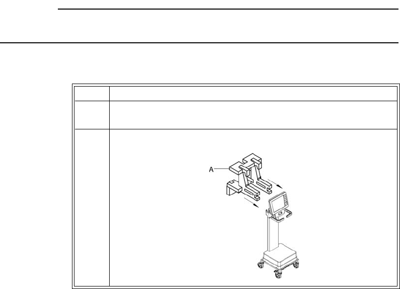
11‐18CleaningandMaintenanceExpressionMR200InstructionsforUse
PrevioususerswhoarenotableorpreparedtodothisshouldinformRoyalPhilipsHealthcare
aboutthenewuser,sothatRoyalPhilipsHealthcarecanprovidethenewuserwithsafety‐related
information.
Packaging the MR200
TopackagetheMR200forshipment,usetheMR200packingmaterialstosafelytransportthe
monitor.
CAUTION
If shipment of the MR200 is required, batteries must be removed prior to transport.
TopacktheMR200
Step Action
1InalocationoutsideoftheMRmagnetroom,ensurethatpoweris
disconnectedandthatbothbatteriesareremovedfromthecart.
2CovertheLCD.InstallfoamAovertheupperportionofthecart.
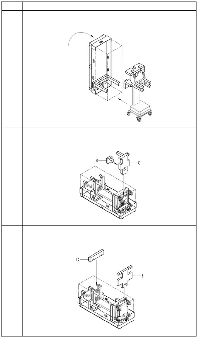
ExpressionMR200InstructionsforUseCleaningandMaintenance11‐19
3Withthecrateorientedasshown,placeitintoanuprightposition.
Rollthecartintothecrate.
4 Carefullylowerthecrate.SlidefoamBintofoamCtheninsertit
betweenthebaseofthecartandthecrate.
5Insert
foamDintofoamA,andinsertfoamEbetweenfoamCand
thecrate.
Step Action
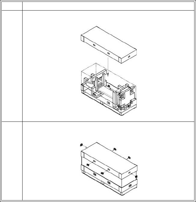
11‐20CleaningandMaintenanceExpressionMR200InstructionsforUse
6Placethelidonthecrate.
7Installalltheclipsintothelidonthecrate,ensuringthateachis
locked.
Step Action

ExpressionMR200InstructionsforUseSpecificationsA‐1
APPENDIX A
Specifications
General
Patient Safety
ConformstoANSI/AAMIES60601‐1.CertifiedtoCAN/CSAC22.2No.60601‐1.
Conformsto93/42/EECasamendedby2007/47/EEC
Defibrillatorprotectionupto5KV
Accordingtodegreeofprotectionagainstharmfulingressofwater:ordinaryequipment,IPX0(enclosedequipment
withoutprotectionagainstingressoffluids)
Whereappropriate,theequipmentcompliestoworldwidestandardsforsafetyandperformanceofeachsystem
feature,whenconsideringtheindicationsforusewithintheMRenvironment.Thisequipmentcompliestothe
followinginternationalindustrystandardsforsafetyandperformance:
•IEC60601‐1,GeneralRequirementsforSafetyofMedicalElectricalEquipment
•IEC60601‐1‐2,GeneralRequirementsforSafety‐ElectromagneticCompatibility
•IEC60601‐1‐6,GeneralRequirementsforSafety‐CollateralStandard:Usability
•IEC60601‐1‐8,GeneralRequirements,TestsandGuidanceforAlarmSystemsinMedicalElectricalEquipment
andMedicalElectricalSystems
•IEC60601‐2‐27,ParticularRequirementsforSafety‐SpecificationforElectrocardiographicMonitoring
Equipment
•IEC60601‐2‐49,ParticularRequirementsforSafety‐SpecificationforMultifunctionPatientMonitoring
Equipment
•IEC80601‐2‐30,MedicalElectricalEquipment‐Part2‐30:ParticularRequirementsfortheSafety,Including
EssentialPerformance,ofAutomaticCyclingNon‐InvasiveBloodPressureMonitoringEquipment
•ISO80601‐2‐61,MedicalElectricalEquipmentParticularRequirementsfortheBasicSafetyandEssential
PerformanceofPulseOximeterEquipmentforMedicalUse
•ISO80601‐2‐55,MedicalElectricalEquipmentParticularRequirementsfortheBasicSafetyandEssential
PerformanceofRespiratoryGasMonitors
•ISO10993‐1,BiologicalEvaluationofMedicalDevices‐Part1:EvaluationandTesting
•ISO10993‐5,BiologicalEvaluationofMedicalDevices‐Part5:TestsforCytotoxicity:Invitromethods
•ISO10993‐10,BiologicalEvaluationofMedicalDevices‐Part10:TestsforIrritationandDelayed‐Type
Hypersensitivity

A‐2SpecificationsExpressionMR200InstructionsforUse
Additionally,thisequipmentcompliestothefollowingnationalorregionalindustrystandardsforsafetyand
performance:
• 1999/5/EC,Radio&TelecommunicationsTermi nalEquipmentDirective
•SAAAS/NZS3200.1.2,GeneralRequirementsforSafety‐ElectromagneticCompatibility
•ANSI/AAMIEC13:2002/(R)2007,CardiacMonitors,HeartRateMeters,andAlarms
•ANSI/AAMISP10:2008,Manual,Electronic,orAutomatedSphygmomanometers
• 2006/66/EC,BatteryDirective
•UL2054:2004Secondarycellsandbatteriescontainingalkalineorothernon‐acidelectrolytes,Standardfor
HouseholdandCommercialBatteries
•IEC62133:2002,Secondarycellsandbatteriescontainingalkalineorothernon‐acidelectrolytes,Standardfor
HouseholdandCommercialBatteries
• 2002/96/EC,DirectiveonWasteofElectricalandElectronicEquipment
•ASTMF2503‐08,StandardPracticeforMarkingMedicalDevicesandotherItemsforSafetyintheMR
Environment
•ASTMF2052‐06,StandardTestMethodforMeasurementofMagneticallyInducedDisplacementForceon
MedicalDeviceinMREnvironment
Power Requirements, Cart
OperatingVoltageRange 100VACto240VAC
FrequencyRange 47Hzto63Hz
Current 1.5A@115VAC/0.7A@240VAC
PowerConsumption,Maximum 65Watts
Battery
TypeCart:Lithium‐Ion
Module:Lithiumpolymer
OperationTimeCart:Maximumoperationtimeisapproximately8hourswhenECG
andSPO2areon,CO2isoff,andNiBPisrunningat5‐minute
intervals(timemaybereducedbyupto2hoursundercertain
conditions,suchasrunningshorterNiBPcycles).Withthecartoff,
insertedandfullychargedbatterieswillnotcompletelydischarge
foratleast72hours.
Module:Approximateoperationtimeofthebatteryis8hours.
ChargeTime Cart:Torechargeafullydischargedbatteryisapproximately12
hourswiththeMR200turnedoff.
Module:Torechargeafullydischargedbatteryisapproximately3
hours.
MinimumVoltage
(Fornormaloperation)
Cart:14.8V
Module:3.4V

ExpressionMR200InstructionsforUseSpecificationsA‐3
Environment
OperatingTemperatureRange 10°Cto35°C(50°Fto95°F)
Storage/TransportTemperatureRange Batteries:0°Cto40°C(32°Fto104°F)
Cart:‐20°Cto50°C(‐4°Fto122°F)
Wirelessmodules:‐25°Cto75°C(‐13°Fto167°F)
Accessories:‐20°Cto60°C(‐4°Fto140°F)
(Whenstoringortransportingintemperaturesbeyondtheranges
specifiedabove,removethedesignatedcomponentandstoreor
moveitappropriately.)
RelativeHumidityRange 15%to80%,non‐condensing
OperatingAltitudeRange Fromsealevelupto10,000feet(3048m)(708mbar)
Storage/TransportAltitudeRange From1020mbarto708mbar
Dimensions and Weights
(Allmeasurementsmadewithoutaccessories)
Height Cart:54.22inches(137.71cm)
WirelessECGmodule:4.7inches(11.9cm)
WirelessSPO2module:5.5inches(13.9cm)
Width Cart:22.15inches(56.26cm)
WirelessECGmodule:2.5inches(6.4cm)
WirelessSPO2module:2.5inches(6.4cm)
Depth Cart:25.25inches(64.14cm)
WirelessECGmodule:0.91inches(2.3cm)
WirelessSPO2module:0.91inches(2.3cm)
Weight Cart:74.06pounds(33.59kg)
WirelessECGmodule:5.4ounces(158.8g)
WirelessSPO2module:5.4ounces(158.8g)
Liquid Crystal Display
Type 800x600pixels,color
ScreenSize 12.1inches(30.7cm)diagonal
SweepSpeed ForECGandSPO2,aspeedof25mm/secondgives9.2secondsof
displaytime,while50mm/secondgives4.6seconds.
Forrespiration,aspeedof0.33,1.56,3.13,6.25,12.5or25mm/
secondisused.
WaveformDisplayMode Fixedtrace,movingerasebar
WaveformDisplayHeight ≥19mm
“FullScreen”DisplayHeight ≥75mm
Batteryindication Timeremaining,redlowwarning
Alarmindication Onehertzflashingfrequencywith50percentdutycycle,visibleat
4metersandlegibleat1meter(assumingavisualacuityof20/20
andwithnolineofsightobstructions).

A‐4SpecificationsExpressionMR200InstructionsforUse
Displayed Parameters
Time Battery‐backedquartzcrystalclock
Alarms Highandlowlimitsselectableforpatientparameters
ECG ECGwaveformscale,displayedleads(2)
HeartRate NormallyderivedfromECG.Maybemanuallyselectedtobe
derivedfrompulseoximetry,orautomaticallyinorderofpriority.
PulseOximeter Pulserate,pulsewaveformandpercentsaturation
Trends Heartrate,respirationrate,NiBP(systolic,mean,diastolic),CO2
andSPO2
CO2 Bothend‐tidalandinspiredCO2
NiBP Pressures(systolic,mean,diastolic)andstatus
RespirationRate RespirationratederivedfrombellowsorCO2
ECG
ECG Amplifier
Protectedagainstdefibrillatorandelectrosurgerypotentials
StandardLeadConfigurations I,II,III,AVR,AVL,AVF
LeadFail Passive,sensingsignalimbalance
ECGInputImpedance >2.5MΩ(accordingtoIEC60601‐2‐27,50.102.3)
Heart Rate
Range 30to249BPM(Adult)
30to300BPM(Neonate,Pediatric)
Accuracy IntheabsenceofanMRIgradientartifact:±1%or±1BPM,
whicheverisgreater.
InthepresenceofanMRIgradientartifact:±1%from30‐200
BPM,±1.5%from200‐250BPM,and(neonatalonly)±2.0%from
251‐300BPM
Resolution 1BPM
Cardiotach
Sensitivity(Monitorfilter) AdultECGmode:>200uV
Neonate/PediatricECGmode:>100uV
Bandwidth Monitor:0.5Hzto40Hz
TallT‐WaveRejectionCapabilityforHeartRate
Indication
2mVwitha1mVQRSamplitude

ExpressionMR200InstructionsforUseSpecificationsA‐5
Alarm Limits (HR)
Lower
Upper
Offor30to249
60to249oroff
Test/Calibrations
SquareWaveTestSignal 60BPM±1BPM,1mV±10%
ECG Supplemental Information, as required by IEC 60601-2-27
HeartRateAveragingMethod Meanfilteringisappliedtotheoutputofthemedianfilterofa
continuouslyupdatinggroupofQRScomplexes.TheECGheart
ratenumericisupdatedtwiceasecond.
TimetoAlarmforTachycardia
B1‐VentTachycardia
1mVpp,206BPM
B2‐VentTachycardia
2mVpp,195BPM
Gain0.5(12.03,11.04,14.1,11.8,11.4)Average:12.1sec(The
monitoringsystemmaytemporarilyexitthealarmcondition
duringthearrhythmiawaveformduration.)
Gain1.0(11.9,11.6,9.2,9.6,10.9)Average:10.6sec
Gain2.0(8.8,9.1,10.3,9.4,12.1)Average:9.9sec
Gain0.5(9.0,10.4,12.3,8.1,10.4)Average:10.0sec
Gain1.0(8.4,7.7,12.5,7.7,8.3)Average:8.9sec
Gain2.0(9.7,12.6,8.9,11.8,8.3)Average:10.3sec
NOTE
Measurements made in FILTER MODE - MONITOR, outside of the MR environment. The alarm condition response
time of some arrhythmia complexes may be affected by MRI gradient artifacts.
ResponseTimeofHeartRateMetertoChange
inHeartRate
HRchangefrom80BPMto120BPM:8.3secaverage
HRchangefrom80BPMto40BPM:7.9secaverage
HeartRateMeterAccuracyandResponseto
IrregularRhythm
A1:Ventricularbigeminy:40BPM
A2:Slowalternatingventricularbigeminy:30BPM
A3:Rapidalternatingventricularbigeminy:115–125BPM
A4:Bidirectionalsystoles58–85BPM
NOTE
Measurements made in FILTER MODE - MONITOR, outside of the MR environment. The accuracy of the indicated
heart rate may be affected by MRI gradient artifacts.

A‐6SpecificationsExpressionMR200InstructionsforUse
Pulse Oximeter
Pulsetonepitchismodulatedbythesaturationvalue
SaturationRange 0to100%
SaturationAccuracy ±3%at70%to100%
PulseMeasurementRange 30BPMto250BPM
PulseAccuracy ±2%or1BPM,whicheverisgreater
WavelengthRange 500nmto1000nm
EmittedLightEnergy <15mW
PulseOximeterCalibrationRange 70%to100%
Alarm Limits
Lower
Upper
Offor50to99
70to99oroff
When“HR”isderivedfromSPO2
Lower
Upper
Offor30to249
60to249oroff
NOTE
Measurement validation: SPO2 accuracy validated in human studies against arterial blood sample reference measured
with a CO-oximeter. In a controlled desaturation study, healthy adult volunteers with saturation levels between 70–100
percent SPO2 were studied. The population characteristics for those studies were:
• about 50% female and 50% male subjects
• 19–27 years of age
• light to black skin tones
A functional tester cannot be used for accuracy assessment of a pulse oximeter monitor; however, it can demonstrate
that a pulse oximeter monitor reproduces a calibration curve that has been independently demonstrated to fulfill a
particular accuracy specification.
SPO2 measurements are statistically distributed; therefore, in accordance to ISO 9919:2005, it is possible that only
two-thirds of the measurements will fall within ± 3 percent of the value measured by the CO-Oximeter.

ExpressionMR200InstructionsforUseSpecificationsA‐7
Non-Invasive Blood Pressure
General Oscillometrictechnology(withaninflatablecuff)determines
systolic,diastolicandmeanarterialpressures
PatientTypes Adult,PediatricandNeonate
Pneumatic Systems
CuffInflationPressure Initial:165mmHgforAdult,130mmHgforPediatric,and100
mmHgforNeonate(allpressuresare±15mmHg)
SubsequentinflationpressuresdeterminedbylastNiBP
measurement
OverpressureProtection Automaticreleaseofcuffpressureifinflationpressureexceeds300
mmHgforAdultandPediatricmodes,and150mmHgforNeonate
mode
UnitofMeasure mmHgorkPa
Measurement Range
Systolic
Adult
Pediatric
Neonate
30mmHgto270mmHg
30mmHgto180mmHg
30mmHgto130mmHg
Mean
Adult
Pediatric
Neonate
20mmHgto255mmHg
20mmHgto160mmHg
20mmHgto120mmHg
Diastolic
Adult
Pediatric
Neonate
10mmHgto245mmHg
10mmHgto150mmHg
10mmHgto100mmHg
Accuracy
PressureMeasurementAccuracy Maximummeanerror±5mmHgwithastandarddeviationofless
than8mmHg
PressureMeasurementResolution 1mmHg
PressureTransducerRange 0to300mmHg

A‐8SpecificationsExpressionMR200InstructionsforUse
Alarm Limits
Systolic
Adult&Pediatric
Lower
Upper
Neonate
Lower
Upper
Mean
Adult&Pediatric
Lower
Upper
Neonate
Lower
Upper
Diastolic
Adult&Pediatric
Lower
Upper
Neonate
Lower
Upper
Offor46to254
46to254oroff
Offor46to124
46to124oroff
Offor26to239
26to239oroff
Offor26to94
26to94oroff
Offor16to224
16to224oroff
Offor16to84
16to84oroff
Modes
Manual Immediateuponoperatorcommand
Automatic Determinationsautomaticallymadewithselectableintervalsof1,
2,2.5,3,5,10,15,20,30and45minutes;and,1,2and4hours

ExpressionMR200InstructionsforUseSpecificationsA‐9
CO2 (Optional)
Sidestream,non‐dispersiveinfraredabsorptiontechnique.Includingmultiplefiltrationsystemandmicroprocessor
logiccontrolofsamplehandlingandcalibration.
Output CO2waveform,EtCO2andFiCO2numericvalues,andrespiration
rate
CO2UnitofMeasure mmHgorkPa
InitializationTime Waveformdisplayedinlessthan20seconds,atanambient
temperatureof25°C;fullspecificationsattainedwithin2minutes
InspiredCO2Measurement Range:3mmHgto50mmHg
Method:LowestreadingoftheCO2waveformintheprevious20
seconds
CO2Accuracy
(Allmeasurementsatgastempof25°C)
±4mmHgor±12%,whicheverisgreater,afterthespecified
warm‐upperiod
CO2MeasurementRange
(InwhichtheCO2accuracyspecificationismet)
0to76mmHgforrespirationratesrangingfrom4to60breaths
perminute,inclusive
CO2Resolution 1mmHg
CO2Stability ShortTermDrift:Driftnottoexceed0.8mmHgover4hours
LongTermDrift:Accuracyspecificationmaintainedovera120‐
hourperiod
ZeroCalibrationInterval Automaticoruserrequested
FlowRate 50mL/minute±10mL/minute
RespirationAccuracy±1breathor±3%whicheverisgreater
RespirationRateRange
(Inwhichtherespirationaccuracyspecification
ismet)
4to100breathsperminute,inclusive
RespirationResolution 1breathperminute
Response(Rise)Time
Adult&Pediatric
Neonate
(Asmeasuredfromthepatientgasinputofthe
completepneumaticcircuit[includingtubing],
from10%to90%ofthemeasuredCO2levels)
800ms
440ms
Compensations
(AutomaticCO2ambientpressure
compensation400to800mmHg)
CompensationsforexpiredO2Balancegas(N2,N2O,O,He)and
AnestheticAgentsB
Usesgascompensationinformationtocorrecttherawcarbon
dioxidevalue

A‐10SpecificationsExpressionMR200InstructionsforUse
A.
(FromOlivierC.Wenker:ReviewofCurrentlyUsedInhalationAnesthetics:PartI.TheInternetJournalofAnesthesiology,1999,Volume
3Number.)
B.
AnestheticAgentEffects
(MACLevels)
AnestheticAgentSensitivityA(uncompensated):Accuracy
specificationwillbemaintainedforhalogenatedanestheticagents
presentatacceptedMAC(MinimumAlveolarConcentration)
clinicallevels.
AnestheticAgentSensitivity(compensated):Testingatagent
levelsdefinedbyacceptedregulatorystandards(i.e.,ISO21647,
ASTMF1456,IEC/CDV60601‐2‐55)currentlyinprocess.
Cross‐sensitivityCompensationError* 0to40mmHg:±1mmHgadditionalerror
41to70mmHg:±2.5mmHgadditionalerror
71to100mmHg:±4mmHgadditionalerror
101to150mmHg:±5mmHgadditionalerror
*AdditionalworstcaseerrorwhencompensationforO2,N2O,
anestheticagents,orheliumiscorrectlyselectedfortheactual
fractionalgasconstituentspresent.
Alarm Limits
End‐tidalCO2
Lower
Upper
Offor5to60
5to80oroff
InspiredCO2 25(Fixed)
Respiration
Lower
Upper
Offor4to40
20to99oroff
GASorVapor Halothane Enflurane Isoflurane Desflurane
MACLevel%(v/v)0.74 1.68 2.00 6.30
Measured
Gas QuantitativeEffectsofGasorVapor
N20 HAL ENF ISO SEVO Xenon Helium DES Ethanol Isopropanol Acetone Methane
Carbon
Dioxide
NE@
60%
NE@
4%
NE@
5%
NE@
5%
NE@
5%
ME1
@80%
NE@
50%
ME2
@15%
NE@
0.1%
NE@
0.1%
NE@
0.1%
NE@
1%
NoEffect(NE)
MinimalEffect1(ME1)=NegativelybiasCarbonDioxidevaluesbyuptoanadditional5mmHgat38mmHg
MinimalEffect2(ME2)=Concentrationsgreaterthan5%willpositivelybiasCarbonDioxidevaluesbyuptoanadditional3mmHgat
38mmHg
*Metereddoseinhalerpropellants:Unspecified

ExpressionMR200InstructionsforUseSpecificationsA‐11
Bellows Respiration
RespirationRateMeasurementRange 0to60breathsperminute
RespirationRateResolution 1breathperminute
RespirationRateAccuracy ±1breathperminute
Gating Connector
PinDesignator SignalName DescriptionandCharacteristics
A DIGITALGATINGPULSE ECG/SPO2digitalgatingpulse
•Peaktopeakvoltage:3.3Vto5.0V
•Pulseduration:10±3ms
BSIGNALGROUND Returnvoltagereferenceforallothersignalpins
CRESPANALOG Analogrespirationgatingwaveformsignal
•Maximumoutputvoltage:±5V
•Maximumcurrent:5mA
•Peak
‐to‐peaksignalvoltage:1V
DECG1VANALOG AnalogECG1‐Voltwaveformsignal
•Outputsignalscaling:1V/mV
•Maximumoutputvoltage:±5V
•Maximumcurrent:5mA
F NEGATIVEGATINGPULSE ECG/SPO2negativedigitalgatingpulse
•Peak‐to‐peaksignalvoltage:‐3.3Vto‐5.0V
•AllothersignalcharacteristicssameasPinA(above)
GSPO240mVANALOG SPO2IR/redanaloggatingwaveformsignal
•Signalscaling:1V/mV
•Maximumoutputvoltage:40mV
HECG1mVANALOG ECGanaloggatingwaveformsignal
•Signalscaling:1mV/mV
•Maximumcurrent:5mA
•Maximumoutputvoltage:20mV
JSPO22VANALOG SPO2IR/redanaloggatingwaveformsignal,maximumoutput
voltage:2V
E,K,L,M,N,OUNUSED Unusedpins
Wiringview
A‐12SpecificationsExpressionMR200InstructionsforUse
ExpressionMR200InstructionsforUseWarrantyB‐1
APPENDIX B
Warranty
Warranty Statement
KoninklijkePhilipsN.V. warrantsthisproduct,otherthanitsconsumableparts,tobefreefrom
defectsinmaterialsandworkmanshipforaperiodoftwelve(12)monthsfromthedateof
originaldeliverytothebuyerortobuyer'sorder,providedthatsameisproperlyoperatedunder
conditionsofnormaluse,andthatperiodicmaintenanceandserviceisperformed.Thissame
warrantyismadeforaperiodofninety(90)daysonconsumableparts.Thiswarrantyshall
becomenullandvoidiftheMR200hasbeenrepairedbysomeoneotherthanKoninklijkePhilips
N.V. oriftheproducthasbeensubjecttomisuse,accident,negligenceorabuse.
KoninklijkePhilipsN.V.’ssoleobligationunderthiswarrantyislimitedtorepairinganMR200
whichhasbeenreportedtotheTechnicalServiceCenterduringnormalbusinesshoursand
shippedtransportationprepaid.KoninklijkePhilipsN.V. shallnotbeliableforanydamages
includingbutnotlimitedtoincidentaldamages,consequentialdamagesorspecialdamages.
Thiswarrantyisinlieuofanyotherwarranties,guaranteesorconditions,including
merchantabilityorfitnessforaparticularpurpose.Theremediesunderthiswarrantyare
exclusiveandKoninklijkePhilipsN.V. neitherassumesnorauthorizesanyonetoassumeforitany
otherobligationinconnectionwiththesaleorrepairofitsproducts.
KONINKLIJKEPHILIPSN.V. PRODUCTSCONTAINPROPRIETARYCOPYRIGHTEDMATERIAL.
ALLRIGHTSRESERVED
B‐2WarrantyExpressionMR200InstructionsforUse

ExpressionMR200InstructionsforUseRegulatoryInformationC‐1
APPENDIX C
Regulatory Information
European Union
Declaration of Conformity
ToobtainacopyoftheDeclarationofConformitytotheEuropeanUnionMedicalDevice
Directive(93/42/EEC)andRadio&TelecommunicationsTerminalEquipmentDirective(1999/5/
EC),and/orRestrictiononHazardousSubstance(RoHS)Directive,contacttheRegulatoryAffairs
DepartmentatInvivo:
407‐275‐3220
‐or‐
1‐800‐331‐3220(toll‐free)
Internationally,pleasecontactyourKeyMarketrepresentative.Gotowww.invivocorp.comfora
listing.
Authorized Representative
TheAuthorizedRepresentativefortheEuropeanUnion(asrequiredbytheMedicalDevice
Directive,93/42/EEC)isasfollows:
PhilipsMedizinSystemeBöblingenGmbH
Hewlett‐PackardStraße2
71034,Böblingen
Germany
Australia
TheAustraliaSponsorisasfollows:
PhilipsElectronicsAustraliaLtd
65EppingRoad,NorthRydeNSW2113
Australia
C‐2RegulatoryInformationExpressionMR200InstructionsforUse
ExpressionMR200InstructionsforUseGuidelinesandReferencesD‐1
APPENDIX D
Guidelines and References
Guidelines for the Prevention of Excessive Heating and Burns
Associated with Magnetic Resonance Procedures
Ingeneral,magneticresonance(MR)imagingisconsideredtobearelativelysafediagnostic
modality.However,theuseofradiofrequencycoils,physiologicmonitors,electronically‐
activateddevices,andexternalaccessoriesorobjectsmadefromconductivematerialshas
causedexcessiveheating,resultinginburninjuriestopatientsundergoingMRprocedures.
HeatingofimplantsandsimilardevicesmayalsooccurinassociationwithMRprocedures,but
thistendsbeproblematicprimarilyforobjectsmadefromconductivematerialsthathave
elongatedshapessuchasleads,guidewires,andcertaintypesofcatheters(e.g.,catheterswith
thermistorsorotherconductingcomponents).
Notably,morethan30incidentsofexcessiveheatinghavebeenreportedinpatientsundergoing
MRproceduresintheUnitedStatesthatwereunrelatedtoequipmentproblemsorthepresence
ofconductiveexternalorinternalimplantsormaterials[reviewofdatafilesfromU.S.Foodand
DrugAdministration,CenterforDevicesandRadiologicalHealth,ManufacturerandUserFacility
DeviceExperienceDatabase,MAUDE,http://www.fda.gov/cdrh/maude.htmlandU.S.Foodand
DrugAdministration,CenterforDevicesandRadiologicalHealth,MedicalDeviceReport,(http://
www.fda.gov/CDRH/mdrfile.html)].Theseincidentsincludedfirst,second,andthirddegree
burnsthatwereexperiencedbypatients.Inmanyofthesecases,thereportsindicatedthatthe
limbsorotherbodypartsofthepatientswereindirectcontactwithbodyradiofrequency(RF)
coilsorotherRFtransmitcoilsoftheMRsystemsortherewereskin‐to‐skincontactpoints
suspectedtoberesponsiblefortheseinjuries.
MRsystemsrequiretheuseofRFpulsestocreatetheMRsignal.ThisRFenergyistransmitted
readilythroughfreespacefromthetransmitRFcoiltothepatient.Whenconductingmaterials
areplacedwithintheRFfield,theresultmaybeaconcentrationofelectricalcurrentssufficient
tocauseexcessiveheatingandtissuedamage.Thenatureofhighfrequencyelectromagnetic
fieldsissuchthattheenergycanbetransmittedacrossopenspaceandthroughinsulators.
Therefore,onlydeviceswithcarefullydesignedcurrentpathscanbemadesafeforuseduring
MRprocedures.Simplyinsulatingconductivematerial(e.g.,wireorlead)orseparatingitfrom
thepatientmaynotbesufficienttopreventexcessiveheatingorburnsfromoccurring.
Furthermore,certaingeometricalshapesexhibitthephenomenonof“resonance”which
increasestheirpropensitytoconcentrateRFcurrents.Attheoperatingfrequenciesofpresent
dayMRsystems,conductingloopsoftensofcentimetersinsizemaycreateproblemsand,
therefore,mustbeavoided,unlesshighimpedanceisusedtolimitRFcurrent.Importantly,even
loopsthatincludesmallgapsseparatedbyinsulationmaystillconductcurrent.
Topreventpatientsfromexperiencingexcessiveheatingandpossibleburnsinassociationwith
MRprocedures,thefollowingguidelinesarerecommended:
D‐2GuidelinesandReferencesExpressionMR200InstructionsforUse
1. PreparethepatientfortheMRprocedurebyensuringthattherearenounnecessary
metallicobjectscontactingthepatient'sskin(e.g.,metallicdrugdeliverypatches,jewelry,
necklaces,bracelets,keychains,etc.).
2. PreparethepatientfortheMRprocedurebyusinginsulationmaterial(i.e.,appropriate
padding)topreventskin‐to‐skincontactpointsandtheformationof“closed‐loops”from
touchingbodyparts.
3. Insulatingmaterial(minimumrecommendedthickness,1cm)shouldbeplacedbetween
thepatient'sskinandtransmitRFcoilthatisusedfortheMRprocedure(alternatively,the
RFcoilitselfshouldbepadded).Forexample,positionthepatientsothatthereisnodirect
contactbetweenthepatient'sskinandthebodyRFcoiloftheMRsystem.Thismaybe
accomplishedbyhavingthepatientplacehis/herarmsoverhis/herheadorbyusingelbow
padsorfoampaddingbetweenthepatient'stissueandthebodyRFcoiloftheMRsystem.
ThisisespeciallyimportantforthoseMRexaminationsthatusethebodycoilorotherlarge
RFcoilsfortransmissionofRFenergy.
4. Useonlyelectricallyconductivedevices,equipment,accessories(e.g.,ECGleads,
electrodes,etc.),andmaterialsthathavebeenthoroughlytestedanddeterminedtobe
safeandcompatibleforMRprocedures,aslistedinthisIFU.
5. CarefullyfollowspecificMRsafetycriteriaandrecommendationsforimplantsmadefrom
electrically‐conductivematerials(e.g.,bonefusionstimulators,neurostimulationsystems,
etc.).
6. Beforeusingelectricalequipment,checktheintegrityoftheinsulationand/orhousingof
allcomponentsincludingsurfaceRFcoils,monitoringleads,cables,andwires.Preventive
maintenanceshouldbepracticedroutinelyforsuchequipment.
7. Removeallnon‐essentialelectricallyconductivematerialsfromtheMRsystem(i.e.,
unusedsurfaceRFcoils,ECGleads,cables,wires,etc.).
8. KeepelectricallyconductivematerialsthatmustremainintheMRsystemfromdirectly
contactingthepatientbyplacingthermaland/orelectricalinsulationbetweenthe
conductivematerialandthepatient.
9. KeepelectricallyconductivematerialsthatmustremainwithinthebodyRFcoilorother
transmitRFcoiloftheMRsystemfromformingconductiveloops.Note:Thepatient's
tissueisconductiveand,therefore,maybeinvolvedintheformationofaconductiveloop,
whichcanbecircular,U‐shaped,orS‐shaped.
10. Positionelectricallyconductivematerialstoprevent“crosspoints”.Forexample,across
pointisthepointwhereacablecrossesanothercable,whereacableloopsacrossitself,or
whereacabletoucheseitherthepatientorsidesofthetransmitRFcoilmorethanonce.
Notably,eventhecloseproximityofconductivematerialswitheachothershouldbe
avoidedbecausesomecablesandRFcoilscancapacitively‐couple(withoutanycontactor
crossover)whenplacedclosetogether.
11. PositionelectricallyconductivematerialstoexitdownthecenteroftheMRsystem(i.e.,
notalongthesideoftheMRsystemorclosetothebodyRFcoilorothertransmitRFcoil).
ExpressionMR200InstructionsforUseGuidelinesandReferencesD‐3
12. Donotpositionelectricallyconductivematerialsacrossanexternalmetallicprosthesis
(e.g.,externalfixationdevice,cervicalfixationdevice,etc.)orsimilardevicethatisindirect
contactwiththepatient.
13. Allowonlyproperlytrainedindividualstooperatedevices(e.g.,monitoringequipment)in
theMRenvironment.
14. Followallmanufacturerinstructionsfortheproperoperationandmaintenanceof
physiologicmonitoringorothersimilarelectronicequipmentintendedforuseduringMR
procedures.
15. ElectricaldevicesthatdonotappeartobeoperatingproperlyduringtheMRprocedure
shouldberemovedfromthepatientimmediately.
16. CloselymonitorthepatientduringtheMRprocedure.Ifthepatientreportssensationsof
heatingorotherunusualsensation,discontinuetheMRprocedureimmediatelyand
performathoroughassessmentofthesituation.
17. RFsurfacecoildecouplingfailurescancauselocalizedRFpowerdepositionlevelstoreach
excessivelevels.TheMRsystemoperatorwillrecognizesuchafailureasasetofconcentric
semicirclesinthetissueontheassociatedMRimageorasanunusualamountofimage
non‐uniformityrelatedtothepositionoftheRFcoil.
Theadoptionoftheseguidelineswillhelptoensurethatpatientsafetyismaintained,especially
asmoreconductivematerialsandelectronically‐activateddevicesareusedinassociationwith
MRprocedures.
References
BasheinG,SyroryG.Burnsassociatedwithpulseoximetryduringmagneticresonanceimaging.
Anesthesiology1991;75:382‐3.
BrownTR,GoldsteinB,LittleJ.Severeburnsresultingfrommagneticresonanceimagingwith
cardiopulmonarymonitoring.Risksandrelevantsafetyprecautions.AmJPhysMedRehabil
1993;72:166‐7.
ChouC‐K,McDougallJA,ChanKW.Absenceofradiofrequencyheatingfromauditoryimplants
duringmagneticresonanceimaging.Bioelectromagnetics1997;44:367‐372.
DempseyMF,CondonB.ThermalinjuriesassociatedwithMRI.ClinRadiol2001;56:457‐65.
DempseyMF,CondonB,HadleyDM.Investigationofthefactorsresponsibleforburnsduring
MRI.JMagnResonImaging2001;13:627‐631.
ECRI,HealthDevicesAlert.AnewMRIcomplication?HealthDevicesAlert.May27,pp.1,1988.
ECRI.ThermalinjuriesandpatientmonitoringduringMRIstudies.HealthDevicesAlert.1991;20:
362‐363.
D‐4GuidelinesandReferencesExpressionMR200InstructionsforUse
FinelliDA,RezaiAR,RuggieriPM,TkachJA,NyenhuisJA,HrdlickaG,SharanA,Gonzalez‐Martinez
J,StypulkowskiPH,ShellockFG.MRimaging‐relatedheatingofdeepbrainstimulation
electrodes:Invitrostudy.AmJNeuroradiol2002;23:1795‐1802.
HeinzW,FrohlichE,StorkT.Burnsfollowingmagneticresonancetomographystudy.(German)Z
Gastroenterol1999;37:31‐2.
http://www.MRIsafety.com
InternationalElectrotechnicalCommission(IEC),MedicalElectricalEquipment,Particular
requirementsforthesafetyofmagneticresonanceequipmentformedicaldiagnosis,
InternationalStandardIEC60601‐2‐33,2002.
JonesS,JaffeW,AlviR.Burnsassociatedwithelectrocardiographicmonitoringduringmagnetic
resonanceimaging.Burns1996;22:420‐1.
KanalE,ShellockFG.BurnsassociatedwithclinicalMRexaminations.Radiology1990;175:585.
KanalE,ShellockFG.Policies,guidelines,andrecommendationsforMRimagingsafetyand
patientmanagement.JMagnResonImaging1992;2:247‐248.
KeensSJ,LaurenceAS.BurnscausedbyECGmonitoringduringMRIimaging.Anaesthesia
1996;51:1188‐9.
KnoppMV,EssigM,DebusJ,ZabelHJ,vanKaickG.Unusualburnsofthelowerextremities
causedbyaclosedconductingloopinapatientatMRimaging.Radiology1996;200:572‐5.
KnoppMV,MetznerR,BrixG,vanKaickG.Safetyconsiderationstoavoidcurrent‐inducedskin
burnsinMRIprocedures.(German)Radiologe199838:759‐63.
KugelH,BremerC,PuschelM,FischbachR,LenzenH,TombachB,VanAkenH,HeindelW.
HazardoussituationintheMRbore:inductioninECGleadscausesfire.EurRadiol2003;13:690‐
694.
NakamuraT,FukudaK,HayakawaK,AokiI,MatsumotoK,SekineT,UedaH,ShimizuY.
Mechanismofburninjuryduringmagneticresonanceimaging(MRI)‐simpleloopscaninduce
heatinjury.FrontMedBiolEng2001;11:117‐29
NyenhuisJA,KildishevAV,FosterKS,GraberG,AtheyW.Heatingnearimplantedmedicaldevices
bytheMRIRF‐magneticfield.IEEETransMagn1999;35:4133‐4135.
RezaiAR,FinelliD,NyenhuisJA,HrdlickG,TkachJ,RuggieriP,StypulkowskiPH,SharanA,
ShellockFG.Neurostimulatorfordeepbrainstimulation:ExvivoevaluationofMRI‐related
heatingat1.5‐Tesla.JournalofMagneticResonanceImaging2002;15:241‐250.
SchaeferDJ.SafetyAspectsofradio‐frequencypowerdepositioninmagneticresonance.MRI
ClinicsofNorthAmerica1998;6:775‐789.
SchaeferDJ,FelmleeJP.Radio‐frequencysafetyinMRexaminations,SpecialCross‐Specialty
CategoricalCourseinDiagnosticRadiology:PracticalMRSafetyConsiderationsforPhysicians,
Physicists,andTechnologists,Syllabus,87thScientificoftheRadiologicalSocietyofNorth
America,Chicago,pp111‐123,2001.
ShellockFG.MagneticResonanceProcedures:HealthEffectsandSafety.CRCPress,LLC,Boca
Raton,FL,2001.
ExpressionMR200InstructionsforUseGuidelinesandReferencesD‐5
ShellockFG.MRsafetyupdate2002:Implantsanddevices.JournalofMagneticResonance
Imaging2002;16:485‐496.
ShellockFG.Radiofrequency‐inducedheatingduringMRprocedures:Areview.Journalof
MagneticResonanceImaging2000;12:30‐36.
ShellockFG.ReferenceManualforMagneticResonanceSafety:2003Edition,Amirsys,Inc.,2003.
ShellockFG,SlimpG.SevereburnofthefingercausedbyusingapulseoximeterduringMRI.
AmericanJournalofRoentgenology1989;153:1105.
ShellockFG,HatfieldM,SimonBJ,BlockS,WamboldtJ,StarewiczPM,PunchardWFB.
Implantablespinalfusionstimulator:assessmentofMRIsafety.JournalofMagneticResonance
Imaging2000;12:214‐223.
SmithCD,NyenhuisJA,KildishevAV.Healtheffectsofinducedelectricalfields:implicationsfor
metallicimplants.In:ShellockFG,ed.Magneticresonanceprocedure:healtheffectsandsafety.
BocaRaton,FL:CRCPress,2001;393‐414.
U.S.FoodandDrugAdministration,CenterforDevicesandRadiologicalHealth(CDRH),Medical
DeviceReport(MDR)(http://www.fda.gov/CDRH/mdrfile.html).Thefilescontaininformation
fromCDRH'sdeviceexperiencereportsondeviceswhichmayhavemalfunctionedorcauseda
deathorseriousinjury.ThefilescontainreportsreceivedunderboththemandatoryMedical
DeviceReportingProgram(MDR)from1984‐1996,andthevoluntaryreportsuptoJune1993.
Thedatabasecurrentlycontainsover600,000reports.
U.S.FoodandDrugAdministration,CenterforDevicesandRadiologicalHealth(CDRH),
ManufacturerandUserFacilityDeviceExperienceDatabase,MAUDE,(http://www.fda.gov/cdrh/
maude.html).MAUDEdatarepresentsreportsofadverseeventsinvolvingmedicaldevices.The
dataconsistsofallvoluntaryreportssinceJune,1993,userfacilityreportssince1991,distributor
reportssince1993,andmanufacturerreportssinceAugust,1996.
D‐6GuidelinesandReferencesExpressionMR200InstructionsforUse
Notes
Notes
Notes
Notes
Notes
Notes
Notes
Notes