Invivo ESSENTIAL MRI PATIENT MONITOR User Manual 989803173791
Invivo Corporation MRI PATIENT MONITOR 989803173791
Invivo >
Users Manual
*989803173791*
989803173791
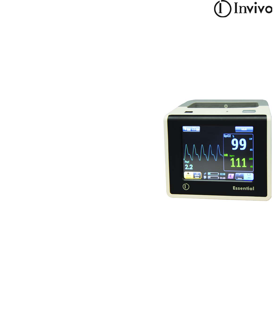
Essential MRI Patient Monitor
(Model 865353)
Instructions for Use
989803173791 Rev 0.6
English

2 989803173791 Rev 0.6

989803173791 Rev 0.6 3
Manufacturer
InvivoCorporation
Orlando,Florida32826
U.S.A.
(407)275‐3220
(800)331‐3220
www.invivocorp.com
Copyright
Copyright©2010,Invivo.Allrightsreserved.PrintedintheUnitedStates.
REF989803173791Rev.A,October2010
Equipment Classification
NOTE
LawsintheUnitedStatesrestrictthisdevicetosalebyorontheorderofaphysician.
EQUIPMENTCLASSIFICATION(accordingtoIEC60601‐1)
Accordingtothetypeofprotection
againstelectricalshock ClassIequipment
Accordingtothedegreeofprotection
againstelectricalshock: TypeCF(defibrillator‐proof)equipment
Accordingtothedegreeofprotection
againstharmfulingressofwater:
IPX2(enclosedequipmenttilted15degrees
withprotectionagainstdrippingliquid).
Accordingtothemethodsofsterilization
ordisinfection:
Non‐sterilizable.Useofliquidsurface
disinfectantsonly.
Accordingtothemodeofoperation: Continuousoperation
Equipmentnotsuitableforuseinthepresenceofflammableanestheticmixturewithair
orwithoxygenornitrousoxide.
4 989803173791 Rev 0.6
Proprietary Information
Thisdocumentandtheinformationcontainedinitisproprietaryandconfidentialinformationof
Invivoandmaynotbereproduced,copiedinwholeorinpart,adapted,modified,disclosedto
others,ordisseminatedwithoutthepriorwrittenpermissionofInvivo.Thisdocumentis
intendedtobeusedbycustomersandislicensedtothemaspartoftheirInvivoequipment
purchase.Useofthisdocumentbyunauthorizedpersonsisstrictlyprohibited.
Invivoprovidesthisdocumentwithoutwarrantyofanykind,impliedorexpressed,including,but
notlimitedto,theimpliedwarrantiesofmerchantabilityandfitnessforaparticularpurpose.
Invivohastakencaretoensuretheaccuracyofthisdocument.However,Invivoassumesno
liabilityforerrorsoromissionsandreservestherighttomakechangeswithoutfurthernoticeto
anyproductshereintoimprovereliability,function,ordesign.Invivomaymakeimprovementsor
changesintheproductsorprogramsdescribedinthisdocumentatanytime.
Neweditionsofthisdocumentwillincorporateallmaterialupdatedsincethepreviousedition.
Updatepackagesmaybeissuedbetweeneditionsandcontainreplacementandadditionalpages.
Notethatpageswhicharerearrangedduetochangesonapreviouspagearenotconsidered
revised.
Thedocumentationpartnumberandrevisionindicatethecurrentedition.Theprintingdate
changeswhenanewrevisionisprinted.(Minorcorrectionsandupdateswhichareincorporated
atreprintdonotcausethedatetochange.)Thedocumentrevisionletterchangeswhen
extensivetechnicalchangesareincorporated.
Contents
989803173791 Rev 0.6Contentsi
Chapter 1: Important Information
Intended Audience . . . . . . . . . . . . . . . . . . . . . . . . . . . . . . . . . . . . . . . . . . . . . . . . . . . . . . . . 1
Warnings . . . . . . . . . . . . . . . . . . . . . . . . . . . . . . . . . . . . . . . . . . . . . . . . . . . . . . . . . . . . . . . 1
Conventions . . . . . . . . . . . . . . . . . . . . . . . . . . . . . . . . . . . . . . . . . . . . . . . . . . . . . . . . . . . . . 2
System Conventions. . . . . . . . . . . . . . . . . . . . . . . . . . . . . . . . . . . . . . . . . . . . . . . . . . . . . . . . . . 2
Document Conventions . . . . . . . . . . . . . . . . . . . . . . . . . . . . . . . . . . . . . . . . . . . . . . . . . . . . . . . 2
Warnings . . . . . . . . . . . . . . . . . . . . . . . . . . . . . . . . . . . . . . . . . . . . . . . . . . . . . . . . . . . . . . 3
Cautions. . . . . . . . . . . . . . . . . . . . . . . . . . . . . . . . . . . . . . . . . . . . . . . . . . . . . . . . . . . . . . . 3
Notes . . . . . . . . . . . . . . . . . . . . . . . . . . . . . . . . . . . . . . . . . . . . . . . . . . . . . . . . . . . . . . . . . 3
Accessories . . . . . . . . . . . . . . . . . . . . . . . . . . . . . . . . . . . . . . . . . . . . . . . . . . . . . . . . . . . . . 4
SpO2 . . . . . . . . . . . . . . . . . . . . . . . . . . . . . . . . . . . . . . . . . . . . . . . . . . . . . . . . . . . . . . . . . 4
Power. . . . . . . . . . . . . . . . . . . . . . . . . . . . . . . . . . . . . . . . . . . . . . . . . . . . . . . . . . . . . . . . . 4
Miscellaneous . . . . . . . . . . . . . . . . . . . . . . . . . . . . . . . . . . . . . . . . . . . . . . . . . . . . . . . . . . 5
Safety. . . . . . . . . . . . . . . . . . . . . . . . . . . . . . . . . . . . . . . . . . . . . . . . . . . . . . . . . . . . . . . . . . 6
Electromagnetic Compatibility (EMC). . . . . . . . . . . . . . . . . . . . . . . . . . . . . . . . . . . . . . . . . . . . . 6
Radios . . . . . . . . . . . . . . . . . . . . . . . . . . . . . . . . . . . . . . . . . . . . . . . . . . . . . . . . . . . . . . . . 6
EMC Emissions . . . . . . . . . . . . . . . . . . . . . . . . . . . . . . . . . . . . . . . . . . . . . . . . . . . . . . . . . . . . . 7
EMC Immunity . . . . . . . . . . . . . . . . . . . . . . . . . . . . . . . . . . . . . . . . . . . . . . . . . . . . . . . . . . . . . . 8
Recommended Separation Distances . . . . . . . . . . . . . . . . . . . . . . . . . . . . . . . . . . . . . . . . . . . . 9
Battery Disposal. . . . . . . . . . . . . . . . . . . . . . . . . . . . . . . . . . . . . . . . . . . . . . . . . . . . . . . . . 10
Disposing of Batteries in Europe . . . . . . . . . . . . . . . . . . . . . . . . . . . . . . . . . . . . . . . . . . . . . . . 10
Disposing of Batteries in the United States . . . . . . . . . . . . . . . . . . . . . . . . . . . . . . . . . . . . . . . 10
List of Symbols. . . . . . . . . . . . . . . . . . . . . . . . . . . . . . . . . . . . . . . . . . . . . . . . . . . . . . . . . . 11
Unpacking the System . . . . . . . . . . . . . . . . . . . . . . . . . . . . . . . . . . . . . . . . . . . . . . . . . . . . 14
Examining the Contents . . . . . . . . . . . . . . . . . . . . . . . . . . . . . . . . . . . . . . . . . . . . . . . . . . . . . . 14
Accessories . . . . . . . . . . . . . . . . . . . . . . . . . . . . . . . . . . . . . . . . . . . . . . . . . . . . . . . . . . . . . . . 14
Carry Case. . . . . . . . . . . . . . . . . . . . . . . . . . . . . . . . . . . . . . . . . . . . . . . . . . . . . . . . . . . . 14
Mount Adapter . . . . . . . . . . . . . . . . . . . . . . . . . . . . . . . . . . . . . . . . . . . . . . . . . . . . . . . . . 15
Roll Stand . . . . . . . . . . . . . . . . . . . . . . . . . . . . . . . . . . . . . . . . . . . . . . . . . . . . . . . . . . . . 16
Chapter 2: Getting Started
System Components . . . . . . . . . . . . . . . . . . . . . . . . . . . . . . . . . . . . . . . . . . . . . . . . . . . . . 17
Battery Operation. . . . . . . . . . . . . . . . . . . . . . . . . . . . . . . . . . . . . . . . . . . . . . . . . . . . . . . . 18
Using Batteries Safely . . . . . . . . . . . . . . . . . . . . . . . . . . . . . . . . . . . . . . . . . . . . . . . . . . . . . . . 18
Main Battery. . . . . . . . . . . . . . . . . . . . . . . . . . . . . . . . . . . . . . . . . . . . . . . . . . . . . . . . . . . 18
Module Battery. . . . . . . . . . . . . . . . . . . . . . . . . . . . . . . . . . . . . . . . . . . . . . . . . . . . . . . . . 20
Charging Batteries . . . . . . . . . . . . . . . . . . . . . . . . . . . . . . . . . . . . . . . . . . . . . . . . . . . . . . . . . . 21
Monitor Overview . . . . . . . . . . . . . . . . . . . . . . . . . . . . . . . . . . . . . . . . . . . . . . . . . . . . . . . . 23
Wireless SpO2 Module Overview . . . . . . . . . . . . . . . . . . . . . . . . . . . . . . . . . . . . . . . . . . . 24
Assigning the Module Network. . . . . . . . . . . . . . . . . . . . . . . . . . . . . . . . . . . . . . . . . . . . . . . . . 25
Changing the Module Network Setting . . . . . . . . . . . . . . . . . . . . . . . . . . . . . . . . . . . . . . 26
Initial System Power-Up. . . . . . . . . . . . . . . . . . . . . . . . . . . . . . . . . . . . . . . . . . . . . . . . . . . 29
Display Panel Overview . . . . . . . . . . . . . . . . . . . . . . . . . . . . . . . . . . . . . . . . . . . . . . . . . . . 33
Chapter 3: Preparation for Use
Using the Monitor. . . . . . . . . . . . . . . . . . . . . . . . . . . . . . . . . . . . . . . . . . . . . . . . . . . . . . . . 37
System Parameters . . . . . . . . . . . . . . . . . . . . . . . . . . . . . . . . . . . . . . . . . . . . . . . . . . . . . . 38
iiContents 989803173791 Rev 0.6
Navigating the Menu Groups and Controls. . . . . . . . . . . . . . . . . . . . . . . . . . . . . . . . . . . . . . . . 38
Controlling Menu Changes. . . . . . . . . . . . . . . . . . . . . . . . . . . . . . . . . . . . . . . . . . . . . . . . 38
Locking and Unlocking the Screen. . . . . . . . . . . . . . . . . . . . . . . . . . . . . . . . . . . . . . . . . . 39
Patient Menu. . . . . . . . . . . . . . . . . . . . . . . . . . . . . . . . . . . . . . . . . . . . . . . . . . . . . . . . . . . . . . . 40
Setup Menu. . . . . . . . . . . . . . . . . . . . . . . . . . . . . . . . . . . . . . . . . . . . . . . . . . . . . . . . . . . . . . . . 41
Service Menu . . . . . . . . . . . . . . . . . . . . . . . . . . . . . . . . . . . . . . . . . . . . . . . . . . . . . . . . . . 42
Network Menu. . . . . . . . . . . . . . . . . . . . . . . . . . . . . . . . . . . . . . . . . . . . . . . . . . . . . . . . . . . . . . 44
Alarm Limits Menu . . . . . . . . . . . . . . . . . . . . . . . . . . . . . . . . . . . . . . . . . . . . . . . . . . . . . . . . . . 45
Sound Menu . . . . . . . . . . . . . . . . . . . . . . . . . . . . . . . . . . . . . . . . . . . . . . . . . . . . . . . . . . . . . . . 49
Chapter 4: Monitoring SpO2
SpO2 Sensor and Wireless SpO2 Module. . . . . . . . . . . . . . . . . . . . . . . . . . . . . . . . . . . . . 51
Connecting the Sensor and Attachments to the WSpO2 Module. . . . . . . . . . . . . . . . . . . . . . . 52
Patient Preparation . . . . . . . . . . . . . . . . . . . . . . . . . . . . . . . . . . . . . . . . . . . . . . . . . . . . . . 53
Applying and Positioning the SpO2 Sensor . . . . . . . . . . . . . . . . . . . . . . . . . . . . . . . . . . . . . . . 53
Positioning the WSpO2 Module . . . . . . . . . . . . . . . . . . . . . . . . . . . . . . . . . . . . . . . . . . . . . . . . 54
Measuring SpO2. . . . . . . . . . . . . . . . . . . . . . . . . . . . . . . . . . . . . . . . . . . . . . . . . . . . . . . . . . . . 55
Waveform and Vital Sign Information . . . . . . . . . . . . . . . . . . . . . . . . . . . . . . . . . . . . . . . . 55
No Data Available Indication . . . . . . . . . . . . . . . . . . . . . . . . . . . . . . . . . . . . . . . . . . . . . . 56
Assessing Suspicious SpO2 Readings. . . . . . . . . . . . . . . . . . . . . . . . . . . . . . . . . . . . . . . . . . . 57
Perfusion Index Value . . . . . . . . . . . . . . . . . . . . . . . . . . . . . . . . . . . . . . . . . . . . . . . . . . . 57
Managing Alarms. . . . . . . . . . . . . . . . . . . . . . . . . . . . . . . . . . . . . . . . . . . . . . . . . . . . . . . . 58
Alarm Types, Priorities and Indications. . . . . . . . . . . . . . . . . . . . . . . . . . . . . . . . . . . . . . . . . . . 58
Physiological Alarm Violations . . . . . . . . . . . . . . . . . . . . . . . . . . . . . . . . . . . . . . . . . . . . . 59
Technical Alarm Violations. . . . . . . . . . . . . . . . . . . . . . . . . . . . . . . . . . . . . . . . . . . . . . . . 60
Alarm Controls . . . . . . . . . . . . . . . . . . . . . . . . . . . . . . . . . . . . . . . . . . . . . . . . . . . . . . . . . . . . . 61
System Messages . . . . . . . . . . . . . . . . . . . . . . . . . . . . . . . . . . . . . . . . . . . . . . . . . . . . . . . 62
Chapter 5: Workflow
Workflow Management . . . . . . . . . . . . . . . . . . . . . . . . . . . . . . . . . . . . . . . . . . . . . . . . . . . 66
Chapter 6: Maintenance and Repair
Maintenance . . . . . . . . . . . . . . . . . . . . . . . . . . . . . . . . . . . . . . . . . . . . . . . . . . . . . . . . . . . 73
Cleaning . . . . . . . . . . . . . . . . . . . . . . . . . . . . . . . . . . . . . . . . . . . . . . . . . . . . . . . . . . . . . . . . . . 73
Cleaning the System . . . . . . . . . . . . . . . . . . . . . . . . . . . . . . . . . . . . . . . . . . . . . . . . . . . . 73
Cleaning the Accessories. . . . . . . . . . . . . . . . . . . . . . . . . . . . . . . . . . . . . . . . . . . . . . . . . 74
Repair . . . . . . . . . . . . . . . . . . . . . . . . . . . . . . . . . . . . . . . . . . . . . . . . . . . . . . . . . . . . . . . . 75
Appendix A: Specifications
General . . . . . . . . . . . . . . . . . . . . . . . . . . . . . . . . . . . . . . . . . . . . . . . . . . . . . . . . . . . . . . . 77
Patient Safety . . . . . . . . . . . . . . . . . . . . . . . . . . . . . . . . . . . . . . . . . . . . . . . . . . . . . . . . . . . . . . 77
Power Requirements . . . . . . . . . . . . . . . . . . . . . . . . . . . . . . . . . . . . . . . . . . . . . . . . . . . . . . . . 77
Battery. . . . . . . . . . . . . . . . . . . . . . . . . . . . . . . . . . . . . . . . . . . . . . . . . . . . . . . . . . . . . . . . . . . . 77
Environment . . . . . . . . . . . . . . . . . . . . . . . . . . . . . . . . . . . . . . . . . . . . . . . . . . . . . . . . . . . . . . . 77
Dimensions and Weights . . . . . . . . . . . . . . . . . . . . . . . . . . . . . . . . . . . . . . . . . . . . . . . . . . . . .78
Display (LCD) . . . . . . . . . . . . . . . . . . . . . . . . . . . . . . . . . . . . . . . . . . . . . . . . . . . . . . . . . . . . . . 78
Displayed Parameters . . . . . . . . . . . . . . . . . . . . . . . . . . . . . . . . . . . . . . . . . . . . . . . . . . . . 78
989803173791 Rev 0.6Contentsiii
Pulse Oximeter. . . . . . . . . . . . . . . . . . . . . . . . . . . . . . . . . . . . . . . . . . . . . . . . . . . . . . . . . . 78
Alarm Limits . . . . . . . . . . . . . . . . . . . . . . . . . . . . . . . . . . . . . . . . . . . . . . . . . . . . . . . . . . . . . . . 79
Power Adapter . . . . . . . . . . . . . . . . . . . . . . . . . . . . . . . . . . . . . . . . . . . . . . . . . . . . . . . . . 79
Power Requirements . . . . . . . . . . . . . . . . . . . . . . . . . . . . . . . . . . . . . . . . . . . . . . . . . . . . . . . . 79
Environment . . . . . . . . . . . . . . . . . . . . . . . . . . . . . . . . . . . . . . . . . . . . . . . . . . . . . . . . . . . . . . . 79
Appendix B: Warranty
Warranty Statement . . . . . . . . . . . . . . . . . . . . . . . . . . . . . . . . . . . . . . . . . . . . . . . . . . . . . . 81
Appendix C: Regulatory Information
European Union . . . . . . . . . . . . . . . . . . . . . . . . . . . . . . . . . . . . . . . . . . . . . . . . . . . . . . . . . 83
Declaration of Conformity. . . . . . . . . . . . . . . . . . . . . . . . . . . . . . . . . . . . . . . . . . . . . . . . . . . . . 83
Authorized Representative . . . . . . . . . . . . . . . . . . . . . . . . . . . . . . . . . . . . . . . . . . . . . . . . . . . . 83
Appendix D: Guidelines and References
Guidelines for the Prevention of Excessive Heating And Burns Associated with Magnetic Reso-
nance Procedures . . . . . . . . . . . . . . . . . . . . . . . . . . . . . . . . . . . . . . . . . . . . . . . . . . . . . . . . . . . 85
References. . . . . . . . . . . . . . . . . . . . . . . . . . . . . . . . . . . . . . . . . . . . . . . . . . . . . . . . . . . . . 87
Notes
ivContents 989803173791 Rev 0.6

989803173791 Rev 0.6Chapter1:ImportantInformation1
Chapter 1: Important Information
Informationregardingthesafety,accessories,installation,andoperationofafullyequipped
EssentialMRIPatientMonitor(Model865353)isincludedinthismanual.Foradditional
informationaboutyouraccessories,pleaseconsultthedocumentationthataccompaniesthe
accessory.
Thisproductwillperforminconformitywiththedescriptioncontainedinthismanualand
accompanyinglabelingwhenassembled,operated,maintained,andrepairedinaccordancewith
theinstructionsprovided.
Thisdevicemustbecheckedperiodically.Amalfunctioningdevicemustnotbeused.Partsthat
arebroken,missing,plainlyworn,distorted,orcontaminatedmustbereplacedimmediately.
Referthedevicetoqualifiedservicepersonnelforrepairorreplacement.Thisdeviceoranyofits
partsmustnotberepairedotherthaninaccordancewithwritteninstructionsprovidedbythe
manufacturer.ThedeviceshallnotbealteredwithoutwrittenapprovalofInvivo.Theuserhas
thesoleresponsibilityforanymalfunctionwhichresultsfromimproperuse,faultymaintenance,
improperrepair,damageoralterationbyanyoneotherthanInvivoorInvivo‐authorizedservice
personnel.
Intended Audience
TheEssentialMRIPatientMonitor(Model865353)isintendedforusebyhealthcare
professionalstrainedintheuseoftheequipmentandvitalsignsmonitoring.
Warnings
BeforeusingtheEssentialMRIPatientMonitor(Model865353),readthewarningshereand
thoseintheSafetysectionbelow.ThewarningsandnotesbelowrefertotheEssentialMRI
PatientMonitor(Model865353)initsentirety.
WARNINGS
• ThoroughlyreadandunderstandtheseInstructionsforUsepriortouse.
•Shockhazardexistsifthesystemisoperatedwithoutcovers.
•UseonlysuppliedpowercordsandconnectonlytoproperlygroundedACoutletsto
avoidelectricalshock.

2Chapter1:ImportantInformation 989803173791 Rev 0.6
WARNINGS
•Patientmotionorpositionoftheaccessoriesmayaffectmeasurementaccuracy.Always
consultaphysicianforinterpretationofmeasurementsprovidedbythesystem.
•Performoperationalverificationpriortouse.Ifthesystemfailstofunctionproperly,
removeitfromuseandcontactInvivoTechnicalSupportpersonnel.
• Screenallpatientsformetallicwires,implants,stents,etc.priortoMRprocedures.These
electricalconductorswillreactwiththeMRenvironmentorwiththeInvivoaccessory(if
applieddirectlyovertheconductor),thusincreasingtheriskofheating.
NOTE
TheEssentialMRIPatientMonitor(Model865353)isnotintendedforuseonapatientbeing
transportedoutsideahealthcarefacility.
Conventions
TheEssentialMRIPatientMonitor(Model865353)usescertainconventionsthroughoutthe
interfacetomakeiteasyforyoutolearnanduse.Thisaccompanyinguserinformationalsouses
documentconventionstoassistyouinfindingandunderstandinginformation.
System Conventions
Theseconventionsareusedinthesystem:
•Operationalcontrolisaccomplishedthroughthedisplaypanel.
•Whencontrolormenuitemsareprovidedonthedisplaypanel,touchingthatcontrolor
itemwillactivateoropenit.
•Toprotectagainstaccidentalchangesofirreplaceabledata,aconfirm/cancelpromptis
associatedwithcertainmenuoptions.Whenapromptisdisplayed,youmustconfirmor
cancelthisaction;otherwise,adelayofapproximately30secondswithoutselectionwillbe
equivalenttoselectingcancel.
Document Conventions
•Allproceduresarenumbered,whileanysub‐proceduresarelettered.Completethesteps
inthesequencepresentedtoensuresuccess.Proceduresareindicatedbythefollowing
table:

989803173791 Rev 0.6Chapter1:ImportantInformation3
•Bulletedlistsindicategeneralinformationaboutaparticularfunctionorprocedure,anddo
notimplyasequentialprocedure.
•Messagesregardingaconditioninthedevicearegivenwithinquotationmarks(“”)spelled
andpunctuatedastheyappearinthesystem,unlessincludedasinformationinatable.
•Controlnames,buttonsandmenuitemsortitlesarespelledandpunctuatedasthey
appearinthesystem.
•Symbolsappearastheyappearonthesystem.
•Selectmeanstotouchortaplightlywithafinger(orstylus)withintheboundariesofa
controlitemonthedisplaypanel.
•Theleftsideofthesystemisonyourleftasyoustandinfrontofthesystem,facingit.The
frontofthesystemisnearestyouasyouoperateit.
•Thefrontofthemoduleisnearestyouasyouoperateit.
Warnings
Warning
WAR NIN G
Warningsprovideinformationyoushouldknowtoavoidinjuringyourself,patientsor
personnel.
Cautions
CAUTION
Cautionsprovideinformationyoushouldknowtoavoiddamagingtheequipmentandsoftware.
Notes
NOTE
Notesprovideadditionalinformationregardingsystemusage.
Step Action
1
2
3

4Chapter1:ImportantInformation 989803173791 Rev 0.6
Accessories
Availableaccessoriesarelistedinthetablesbelow.OnlyuserecommendedInvivopatient
sensors,grips,etc,asotherbrandsmaycompromisethesafetyandaccuracyofthesystem.
SpO2
Power
Description PartNumber
QuickConnectSpO2Clip,Adult 989803166531
QuickConnectSpO2Clip,Pediatric 989803166541
QuickConnectSpO2Grip,Adult,20/box 989803166551
QuickConnectSpO2Grip,Infant,20/box 989803166571
QuickConnectSpO2Grip,Neonatal,20/box 989803166581
QuickConnectSpO2Grip,Pediatric,20/box 989803166561
QuickConnectSpO2Grip,StarterPack 989803167111
QuickConnectSpO2Sensor,MRI 989803161991
WirelessSpO2Module(Expression) 989803163111
WirelessSpO2Module(Precess‐Blueversion) 989803172431
Description PartNumber
MainBattery989803171671
ModuleBattery9065
PowerAdapter 989803171691
PowerCord,Brazil250V989803173901
PowerCord,European220‐230V453564177501
PowerCord,UnitedKingdom220‐240V989803174171
PowerCord,US110V989803168211
PowerCord,Universal220V AS18A

989803173791 Rev 0.6Chapter1:ImportantInformation5
Miscellaneous
Description PartNumber
CarryCase989803171711
MountAdapter 989803171681
RollStand 989803173761
UniversalHolderPoleKit(forusewithRollStand) 989803174281
InformationforUseManual,Chinese,Simplified989803174041
InformationforUseManual,Chinese,Traditional989803174081
InformationforUseManual,Czech989803173911
InformationforUseManual,Dutch989803173921
InformationforUseManual,English989803173791
InformationforUseManual,Finnish 989803173931
InformationforUseManual,French989803173941
InformationforUseManual,German989803173951
InformationforUseManual,Greek 989803173961
InformationforUseManual,Hungarian989803173971
InformationforUseManual,Italian 989803173981
InformationforUseManual,Japanese 989803173991
InformationforUseManual,Norwegian 989803174001
InformationforUseManual,Polish 989803174011
InformationforUseManual,Portuguese 989803174021
InformationforUseManual,Russian 989803174031
InformationforUseManual,Slovak 989803174051
InformationforUseManual,Spanish 989803174061
InformationforUseManual,Swedish 989803174071
InformationforUseManual,Turkish 989803174091
ServiceManual 989803173771

6Chapter1:ImportantInformation 989803173791 Rev 0.6
Safety
Electromagnetic Compatibility (EMC)
Thesystemisintendedforuseintheelectromagneticenvironmentspecifiedbelow.Giventhe
system’selectromagneticemissionsandimmunitycharacteristics,thecustomerortheuser
shouldassurethatthesystemisusedwithinsuchanenvironment.
Radios
FrequencyRange:2402to2482MHz.
ModulationType:GMSK.
MonitorEIRP:4.2dBm(peak).
WSpO2EIRP:0dBm(peak)
EMC WA R NINGS EMC WA R NINGS
•OperationofthesystemoutsidethespecificationsindicatedinAppendixAmaycause
inaccurateresults.
•Theuseofportableandmobileradio‐frequency(RF)communicationsequipmentcan
affecttheoperationofthisdevice.
•TheuseofaccessoriesandcomponentsotherthanthosespecifiedintheAccessorieslist
accompanyingtheseinstructionsforuse(withtheexceptionofitemssoldbyInvivofor
theequipmentorsystemasreplacementpartsforinternalcomponents)willresultin
increasedemissionsordecreasedimmunityoftheequipmentorsystem.
•Thesystemshouldnotbeusedadjacenttoorstackedwithotherequipment(except
otherInvivoequipment,asdetailedinthisdocument)andthatifadjacentorstackeduse
isnecessary,theequipmentorsystemmustbeobservedtoverifynormaloperationin
theconfigurationinwhichitwillbeused.
•ThesystemneedstobeinstalledandputintoserviceaccordingtotheEMCinformation
providedbelow.PortableandmobileRFcommunicationsequipmentcanaffectmedical
electricalequipment.ThesystemmaybeinterferedwithbyotherequipmentwithCISPR
emissionrequirements.

989803173791 Rev 0.6Chapter1:ImportantInformation7
EMC Emissions
Electromagneticemissionsistheabilityofaproduct,adevice,orasystemtointroduce
intolerableelectromagneticdisturbancesintotheuseenvironment.
GuidanceandManufacturer’sDeclaration–
ElectromagneticEmissions
EmissionsTest Compliance ElectromagneticEnvironment‐Guidance
TheEssentialMRIPatientMonitor(Model865353)isintendedforuseintheelectromagneticenvironment
specifiedbelow.ThecustomerortheuseroftheEssentialMRIPatientMonitor(Model865353)shouldassure
thatitisusedinsuchanenvironment.
RFEmissions
CISPR11 Group1
ThesystemusesRFenergyonlyforitsinternalfunctions.
Therefore,itsRFemissionsareverylowandarenot
likelytocauseanyinterferenceinnearbyelectronic
equipment.
RFEmissions
CISPR11 ClassA
Thesystemissuitableforuseinallestablishments,other
thandomesticestablishmentsandthosedirectly
connectedtothepubliclow‐voltagepowersupply
networkthatsuppliesbuildingsusedfordomestic
purposes.
HarmonicEmissions
IEC61000‐3‐2ClassA
VoltageFluctuations/flicker
emissions
IEC61000‐3‐3
Complies
8Chapter1:ImportantInformation 989803173791 Rev 0.6
EMC Immunity
Electromagneticimmunityistheabilityofaproduct,adevice,orasystemtofunction
satisfactorilyinthepresenceofelectromagneticinterference.
GuidanceandManufacturer’sDeclaration‐ElectromagneticImmunity
ImmunityTest IEC60601
TestLevel
Compliance
Level ElectromagneticEnvironment‐Guidance
TheEssentialMRIPatientMonitor(Model865353)isintendedforuseintheelectromagneticenvironment
specifiedbelow.ThecustomerortheuseroftheEssentialMRIPatientMonitor(Model865353)shouldassure
thatitisusedinsuchanenvironment.
ConductedRF
IEC61000‐4‐6
RadiatedRF
IEC61000‐4‐3
3Vrms
150KHzto80MHz
3V/m
80MHzto2.5GHz
V1=3Vrms
E1=3V/m
PortableandmobileRFcommunications
equipmentshouldnotbeusedclosertoanypart
ofthesystem(includingcabling)thanthe
recommendedseparationdistance,ascalculated
bytheequationapplicabletothefrequencyof
thetransmitter.Recommendedseparation
distance:
d=(3.5/V1)
d=(3.5/E1)
(80MHzto800MHz)
d=(7/E1)
(800MHzto2.5GHz)
WherePisthemaximumtransmitteroutput
powerratinginwatts(W),accordingtoitsmanu‐
facturer,anddistherecommendedseparation
distanceinmeters(m).
FieldstrengthsfromfixedRFtransmitters,as
determinedbyanelectromagneticsitesurvey,a
shouldbelessthanthecompliancelevelineach
frequencyrange.b
Interferencemayoccurinthevicinity
ofequipmentmarkedwiththis
symbol:
NOTES
•At80MHzand800MHz,thehigherfrequencyrangeapplies.
•Theseguidelinesmaynotapplyinallsituations,aselectromagneticpropagationisaffectedbyabsorption
andreflectionfromstructures,objectsandpeople.
aFieldstrengthsfromfixedtransmitters,suchasbasestationsforradio(cellular/cordless)telephonesandland
mobileradios,amateurradio,AMandFMradio,andTVbroadcastscannotbepredictedtheoreticallywith
accuracy.ToassesstheelectromagneticenvironmentduetofixedRFtransmitters,anelectromagneticsite
surveyshouldbeconsidered.IfthemeasuredfieldstrengthinthesystemlocationexceedstheapplicableRF
compliancelevelabove,thesystemshouldbeobservedtoverifynormaloperation.Ifabnormaloperationis
observed,additionalmeasuresmaybenecessary,suchasreorientingorrelocatingthesystem.
bOverthefrequencyrange150KHzto80MHz,fieldstrengthsshouldbelessthan3V/m.
P
P
P

989803173791 Rev 0.6Chapter1:ImportantInformation9
Recommended Separation Distances
ThesystemisintendedforuseinanelectromagneticenvironmentwhereradiatedRF
disturbancesarecontrolled.Thecustomeroruserofthesystemcanhelpprevent
electromagneticinterferencebymaintainingaminimumdistancebetweenportableandmobile
RFcommunicationsequipment(transmitters)andthesystemasrecommendedbelow,according
tothemaximumoutputpowerofthecommunicationsequipment.
RecommendedSeparationDistancesbetweenPortableandMobileRFCommunicationsEquipment
andtheSystem
RatedMaximum
OutputPowerof
Transmitter
(W)
SeparationDistanceAccordingtoFrequencyofTransmitter(m)
150KHzto80MHz
d=(3.5/V1)
80MHzto800MHz
d=(3.5/E1)
800MHzto2.5GHz
d=(7/E1)
TheEssentialMRIPatientMonitor(Model865353)isintendedforuseintheelectromagneticenvironment
specifiedbelow.ThecustomerortheuseroftheEssentialMRIPatientMonitor(Model865353)shouldassure
thatitisusedinsuchanenvironment.
0.01 0.117 0.117 0.233
0.1 0.369 0.369 0.738
1 1.167 1.167 2.333
10 3.689 3.689 7.379
100 11.667 11.667 23.333
Fortransmittersratedataminimumoutputpowernotlistedabove,therecommendedseparationdistance(d)
inmeters(m)canbeestimatedusingtheequationapplicabletothefrequencyofthetransmitter,wherePisthe
maximumoutputpowerratingofthetransmitterinwatts(W)accordingtoitsmanufacturer.
NOTES
•At80MHzand800MHz,thehigherfrequencyrangeapplies.
•Theseguidelinesmaynotapplyinallsituations,aselectromagneticpropagationisaffectedbyabsorption
andreflectionfromstructures,objectsandpeople.
P
P
P

10Chapter1:ImportantInformation 989803173791 Rev 0.6
Battery Disposal
Thesystemuseslithiumbatteriesthataresubjecttostrictdisposalregulationsforuserand
environmentalsafety.
Caution
CAUTIONS
•Storebatteriesinadryplace,between0°Cto40°C.
• Neverheatorthrowabatteryintofire.Heatingthebatterywilldamagethesafety
circuitry,whichcancauseruptureorignitionofthebattery.
• Neverdisassemblethebattery.Thebatteriescontainhazardousmaterialthatmustbe
recycledordisposedofproperly.(Refertothedisposalguidelinesbelow.)
Disposing of Batteries in Europe
TheEuropeanCommunity(EC)hasissuedtwodirectivesregardingbatterydisposal:91/157/EEC
and93/86/EEC.Eachmembercountryimplementstheseindependently.Thus,ineachcountry
themanufacturers,importers,andusersareresponsiblefortheproperdisposalorrecyclingof
batteries.Confirmproperdisposalrequirementswithyourhealthcarefacilityordistributor.
Disposing of Batteries in the United States
LithiumbatteriesareneitherspecificallylistednorexemptedfromtheFederalEnvironmental
ProtectionAgency(EPA)hazardouswasteregulations,asconveyedbytheResources
ConservationandRecoveryAct(RCRA).Theonlymetalofpossibleconcerninthebatteryisthe
lithiummetal,whichisnotlistedorcharacterizedasatoxichazardouswaste.Asignificant
amountofspentcellsandbatteriesthatareuntreatedandnotfullydischargedareconsideredas
reactivehazardouswaste.Thus,hazardouswasteofspentcellsandbatteriescanbedisposed
aftertheyarefirstneutralizedthroughanapprovedsecondarytreatmentpriortodisposal(as
requiredbyU.S.LandBanRestrictionoftheHazardousandSolidWasteAmendmentsof1984).
Disposalofspentbatteriesmustbeperformedbyanauthorized,professionaldisposalcompany,
whichhastheknowledgeintherequirementsoftheFederal,theStateandtheLocalauthorities
regardinghazardousmaterials,transportation,andwastedisposal.Confirmproperdisposal
requirementswithyourhealthcarefacility,distributor,and/orlocalEPAoffice.
989803173791 Rev 0.6Chapter1:ImportantInformation11
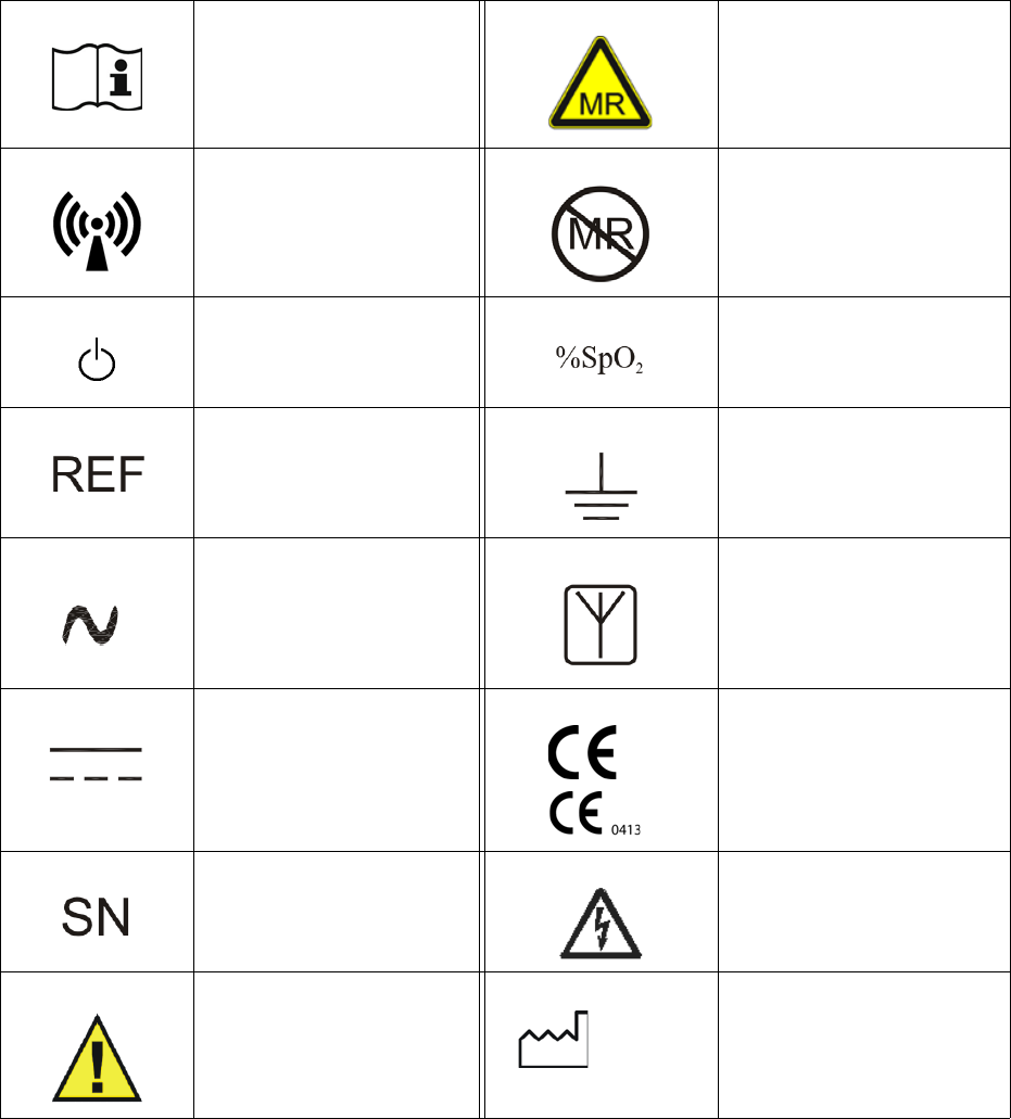
List of Symbols
Thefollowingsymbolsareusedonthesystem,packingmaterials,andinthisdocument:
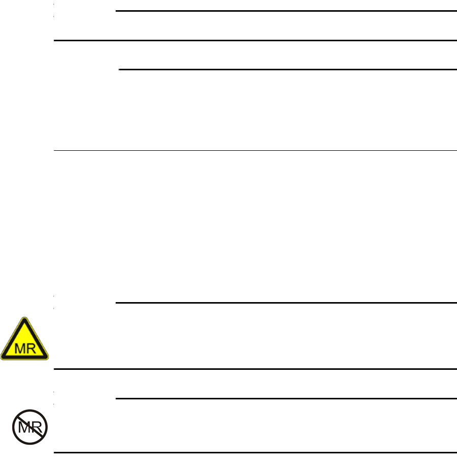
Attention,consult
accompanyingdocuments
MRConditional:Useinthe
MRenvironmentisrestricted
tocertainconditionsofuseto
ensurepatientandoperator
safety.
Non‐ionizingradiationNotMRsafe
Poweron/offPercentoxygenpulse
saturation
Productpartnumber Earthground
Alternatingcurrent Antenna
Directcurrent Deviceconformstothe
MedicalDeviceDirective
Productserialnumber WarningShockHazard
Warning/Caution
Dateofmanufacture
YYYY‐MM
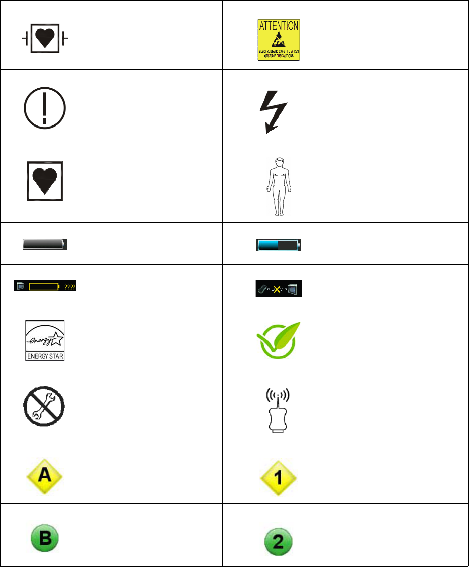
12Chapter1:ImportantInformation 989803173791 Rev 0.6
Defibrillator‐ProoftypeCF
equipment(IEC60601‐1)
protectionagainstshock
Attention:Electrostaticsafety
device,observeprecautions
Potentialrestrictionsfor
equipmentincludingradios
mayapplywithinoneormore
European(EU)member
states.
Dangerousvoltage
TypeCFappliedpart Patient
MainbatterygaugeModulebatterygauge
NoBatteryCommunications No(Module)Communications
EnergyStarratedproduct GreenSealproduct
Donotadjustwithout
referringtoservicemanual
Radionetwork(wireless
modules)
NetworkANetwork1
NetworkBNetwork2
989803173791 Rev 0.6Chapter1:ImportantInformation13
NetworkCNetwork3
NetworkDNetwork4
NetworkENetwork5
Deviceconformstothe
R&TTEDirective(Radio&
TelecommunicationsTermina l
Equipment)
CanadianStandards
Association(CSA)SafetyMark
fortheUnitedStatesand
Canada
FederalCommunications
Commission
Disposeofthebatteryin
accordancewithyour
country’srequirements
Disposeofelectrical
equipmentinaccordance
withyourcountry’s
requirements
Indoor,drylocationuseonly
Deviceconformstothe
ElectricalApplianceand
MaterialsLawofJapan
Externalpowersupply
internationalefficiencymark,
level4
UnderwritersLaboratories
RecognizedComponent
Mark,complianceinCanada
andU.S.A.

14Chapter1:ImportantInformation 989803173791 Rev 0.6
Unpacking the System
Removethecontentsfromtheshippingcontainer(s).Carefullyexamineallitemsforsignsof
damagethatmayhaveoccurredduringshipment.Also,checkallitemsagainstthepackinglist
andthepurchaserequest.
Toreportshippingdamageortoresolveanyissuesorconcernswithyourorder,contactInvivo
CustomerService.(Saveallpackingmaterialsandrelatedshippingdocuments,asthesewillbe
requiredtoprocessadamageclaimwiththecarrier.)
CAUTION
TheEssentialMRIPatientMonitor(Model865353)mustbeusedandstoredaccordingtothe
environmentalspecificationsinAppendixA.Failuretofollowthesespecificationsmayaffect
systemaccuracy.
Examining the Contents
Thesystemincludestheseitems:
•Monitorandbattery
•Poweradapter(notMRsafe)
•Powercord
•IFUmanual
• WirelessSpO2module,batteryandaccessories(optional)
Accessories
Optionalaccessoriesareavailabletoprotect,carryandmountthesystem.
CAUTION
Whenusingtheaccessoriesmakesurethattheviewofthedisplaypanelisnotobstructed.
Carry Case
Thecarrycase(REF989803171711)offersconvenientprotectedstorageforthemonitor,even
duringoperation.Alargeclearwindowallowsvisualandoperationalaccesstothedisplaypanel,
whilesideandrearpocketsofferstorageformodulesandaccessories.
989803173791 Rev 0.6Chapter1:ImportantInformation15
Caution
CAUTIONS
•Donotplacemagneticitemsinsidethecarrycase,astheycouldbeinadvertentlybrought
intotheMRIsystemroom.
•Ensurethatthealarmtoneisaudiblewhenoperatingthemonitorusingthecarrycase.
•Usecautionwhenoperatingthemonitorusingthecarrycase,asthealarmlightwillnotbe
visible.
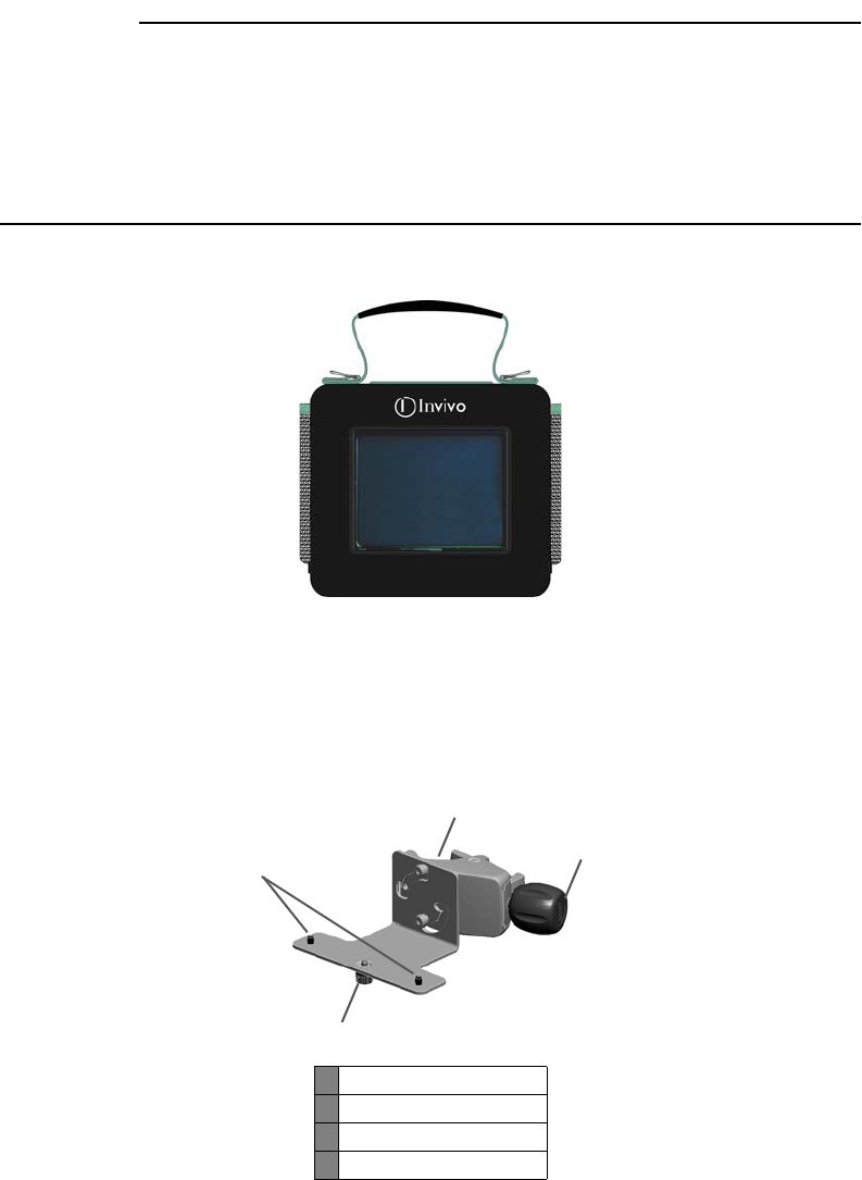
Mount Adapter
Themountadapter(REF989803171681)isasecuresolutionwhenattachingthemonitortoa
poleorrail.
1Pins
2Thumbscrew
3Clamp
4Knob
1
2
3
4
16Chapter1:ImportantInformation 989803173791 Rev 0.6
Toinstallthemonitorontothemountadapter,followthestepsbelow:
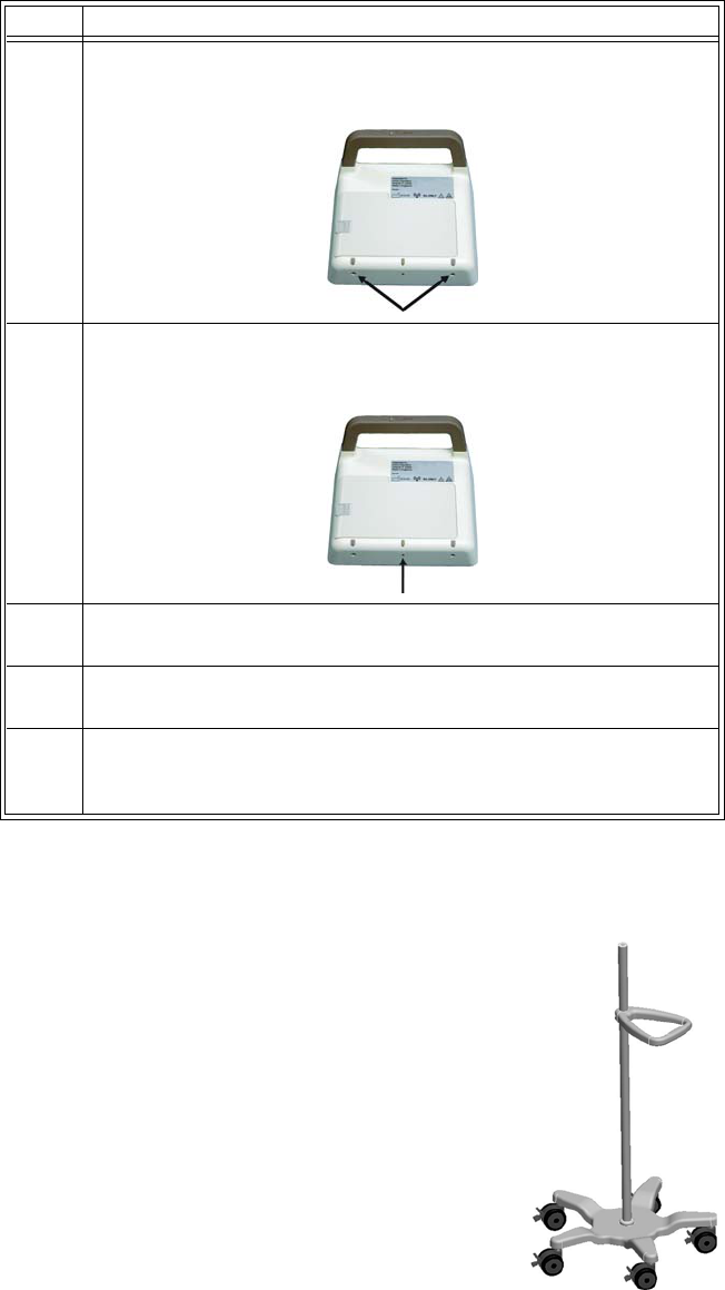
Roll Stand
Therollstand(REF989803173761)offersawheeledmobilitysolution
whentransportingthemonitor(mountadapteroptionalsorequired).
And,forconvenientstorageofthemoduleandaccessories,theUniversal
HolderPoleKit(REF989803174281)isavailable.
Step Action
1Alignthepins(Item1)ofthemountadaptertothelocatorholesin
thebaseofthemonitor.
2InserttheThumbscrew(Item2)intothebaseofthemonitorthen
tightentosecurethemonitortothemount.
3Withthemonitorinthedesiredlocation,placetheclamp(Item3)
aroundapoleorrailthensecurelytightentheknob(Item4).
4Ifneeded,pivotthemounthorizontallyorverticallytoorientthe
monitorforviewing.
5Ifneeded,loosentheknob(Item4)slightlytoreadjustthemonitor
fortheoptimumviewinganglethenretightentheknob.This
completestheprocedure.
989803173791 Rev 0.6Chapter2:GettingStarted 17
Chapter 2: Getting Started
TheEssentialMRIPatientMonitor(Model865353)isintendedforusebyhealthcareprofessionals
monitoringpulseoximetryandpulserateinanMRIsystemroomandincloseproximitytothe
scannermagnet.Additionally,thismonitoringisprovidedbefore,duringandafteractivescanning
intheMRIenvironment.
Thesystemcombineswirelesscommunications,radiofrequencyshielding,digitalsignal
processingandadaptablemountingtechnologiestoprovideaccurate,continuousandreliable
patientmonitoringperformanceinthedynamicMRIenvironment.
TheEssentialMRIPatientMonitor(Model865353)canbeconfigured,accessedandadjustedfor
theuniquevitalneeds,conditionsandsituationsofawidespectrumofpatientsfromneonateto
adult,specifically:
•Criticallyillpatients
• Interventionprocedures
•Intraoperativeprocedures
•PatienttransportwithintheMRenvironment
NOTE
Thesystemissuitableforuseinthepresenceofelectrosurgery.
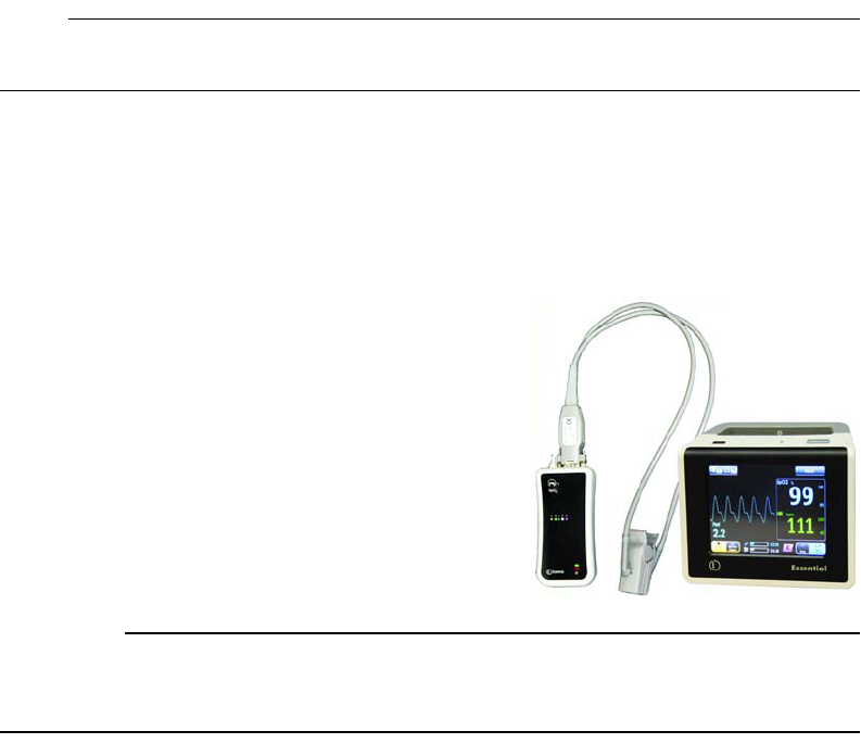
System Components
ThecomponentsthatcompriseaworkingEssentialMRI
PatientMonitor(Model865353)systemincludethe
monitorandaWSpO2modulewithattachments.
CAUTION
Tominimizethechanceofimageartifacts,noneofthemonitoringcomponentsshouldbeplaced
withintheMRIFieldofView.

18Chapter2:GettingStarted989803173791 Rev 0.6
Battery Operation
TheEssentialMRIPatientMonitor(Model865353)operatesfromrechargeablebatteriesthat
provideapproximately8hoursofcontinuouspower.Visualindicationsofthechargedcapacityof
thebatteriesisconstantlyreported,whilealarmsprovidealertswhenlowpowerconditionsare
detected.
Using Batteries Safely
Thebatteriesinthissystemarenon‐magneticandcanbehandledsafelyintheMRsystemroom.
WAR NIN G
DonotuseortakethepoweradapterinsidetheMRsystemroom.Thedeviceismagneticand
willbepulledintotheMRsystem.Thedeviceisintendedforusewiththemainbatteryandthe
modulebatteryonlywhenoutsidetheMRsystemroom.
Batterieshavelifecycles.Whentheequipmentoperatingtimeprovidedbybatterypower
becomesmuchshorterthanusual,thebatterylifeisatanend.Immediatelyremoveabattery
thathasanexpiredlifecycleandreplaceitwithanewInvivospecifiedbattery;refertoBattery
DisposalinChapter1whendiscardingabattery.Toensurethesafetyofoperatorsandpatients,
observethefollowingwarningsandcautions.
WAR NIN G
Stopusinganybatterythatexhibitsabnormalheat,odor,color,deformation,orother
condition.Ifabatteryispuncturedorifbatteryliquidleaksontoyourskinorclothing,
immediatelywashtheareaandclothingwithfreshwater.Ifbatteryliquidgetsintoyoureyes,
donotrubyoureyes;immediatelyflushyoureyeswithcleanwaterandconsultaphysician.
CAUTIONS
•Ifthebatterycontactsbecomedirty,wipethemcleanwithadryclothbeforeuse.
• Keepmetalobjectsawayfromthebatterycontacts.
Main Battery
Themainbatteryfitsthecontourofthemonitorandlatchesintothebatterycompartment.
CAUTION
Neverforcethebatteryintothebatterycompartmentasdamagetothebatteryand/orthe
monitorcouldoccur.
989803173791 Rev 0.6Chapter2:GettingStarted 19
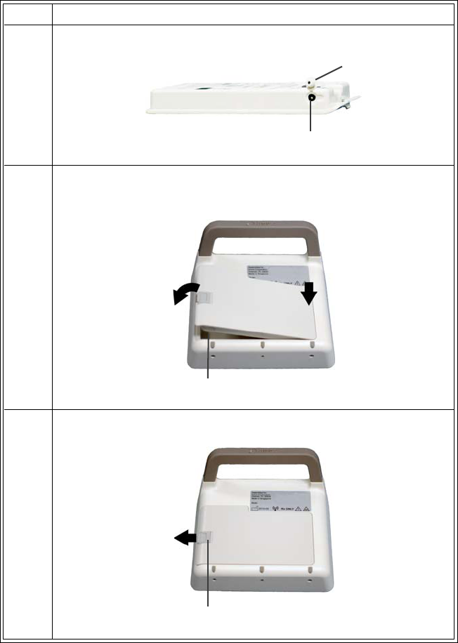
Installing the main battery
Toinstallthemainbatteryfollowthesesteps:
Step Action
1PlacethecoverovertheDCinletonthemainbattery.
2Lowerthemainbatteryintothebatterycompartmentthenpivotit
intoplace,asshownbelow.
3Slidethelockingtabtotheleftuntillatched.
Cover
DC inlet
Battery compartment
Locking tab
20Chapter2:GettingStarted989803173791 Rev 0.6
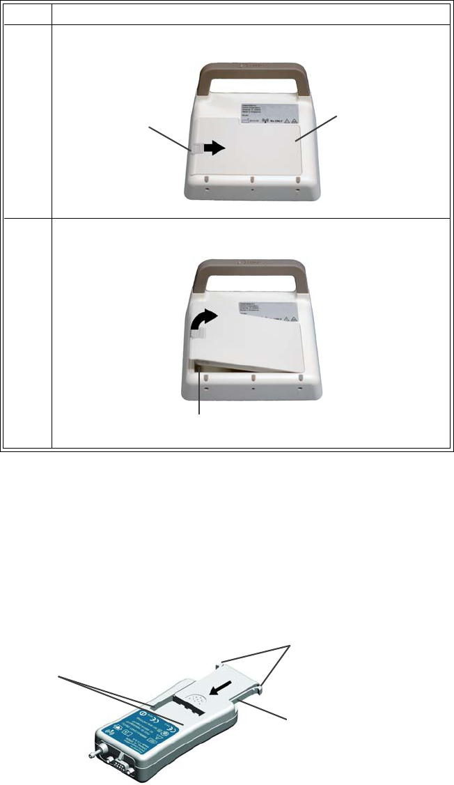
Removing the main battery
Toremovethemainbatteryfollowthesesteps:
Module Battery
Themodulebatterylatchesintothewirelessmodule.
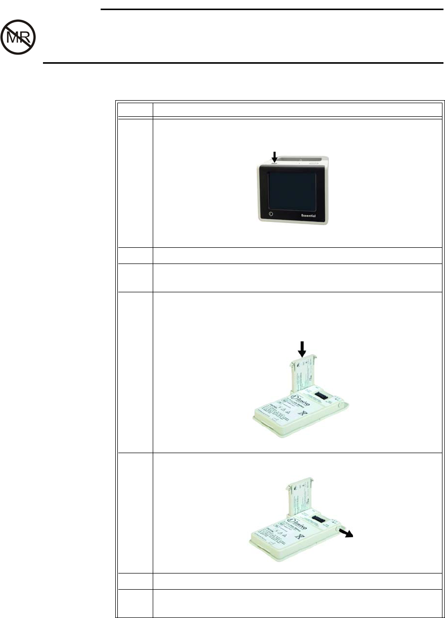
Installing the module battery
Toinstallthemodulebattery,slidethebatteryinbetweentheslotsonthemoduleuntilboth
lockingtabslatch.
Step Action
1Slidethelockingtabonthemainbatterytotheright.
2Liftthemainbatteryoutofthebatterycompartment.
Locking tab Main battery
Battery compartment
Slot
Locking tab
Module battery
989803173791 Rev 0.6Chapter2:GettingStarted 21
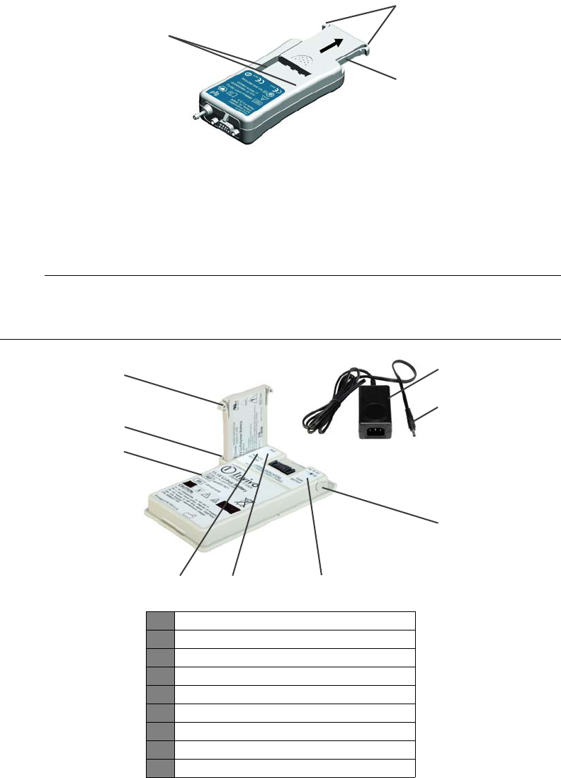
Removing the module battery
Toremovethemodulebattery,pressbothlockingtabsandthenslidethebatteryoutofthe
module.
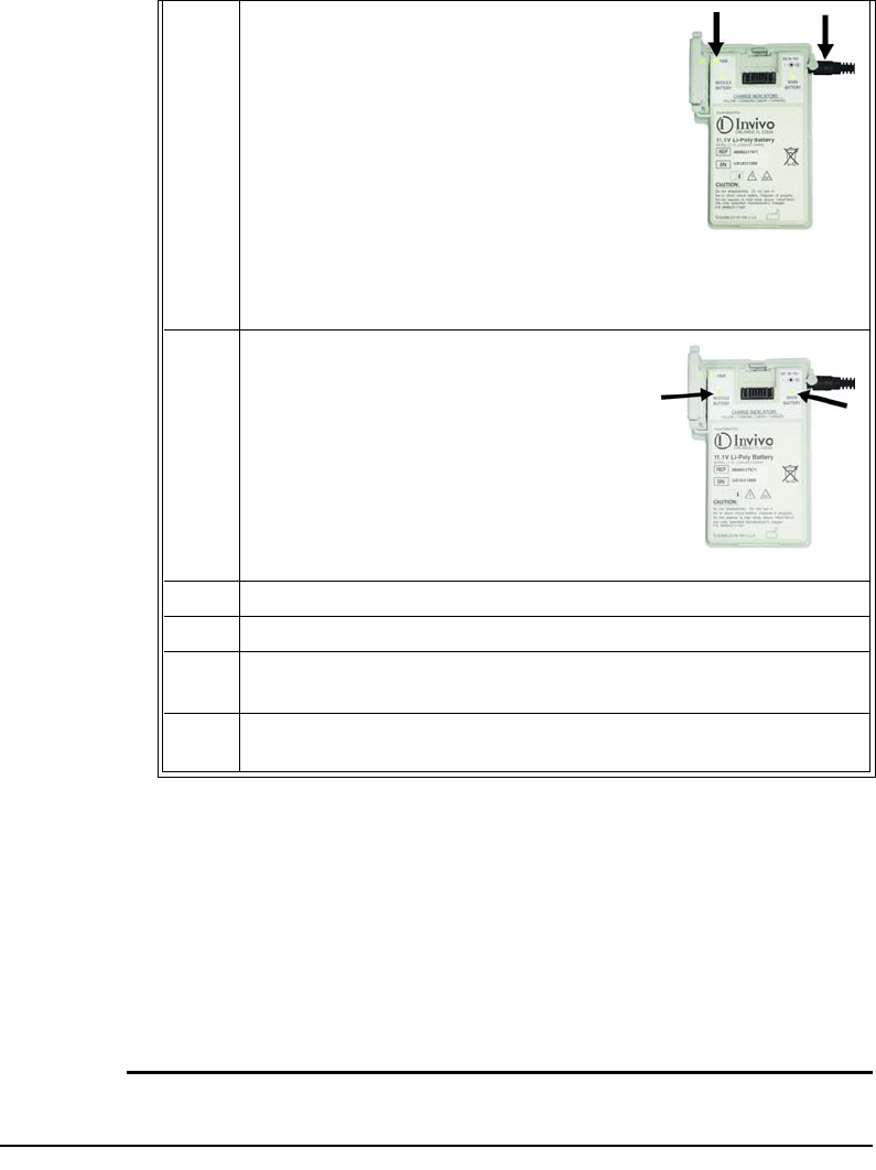
Charging Batteries
Theintelligentcharger,anintegralpartofthemainbatteryassembly,simultaneouslychargesthe
mainandmodulebatteries,whiletheexternalpoweradaptersuppliestheappropriateDCinput.
NOTE
Beforeinitialuse,placethemainbatteryonthechargerforatleast5seconds,asthebatteryis
shippedinahibernating,partiallycharged,condition.
Slot
Locking tab
Module battery
1Modulebattery
2Poweradapter(ACcordnotshown)
3DCplug
4DCinlet(withcover)
5Mainbatterychargeindicator
6Powerindicator
7Modulebatterychargeindicator
8Mainbattery
9Chargingbay
3
4
1
8
2
6
75
9
22Chapter2:GettingStarted989803173791 Rev 0.6
WAR NIN G
DonotuseortakethepoweradapterinsidetheMRsystemroom.Thedeviceismagneticand
willbepulledintotheMRsystem.Thedeviceisintendedforusewiththemainbatteryandthe
modulebatteryonlywhenoutsidetheMRsystemroom.
Tochargebatteriesfollowthesesteps:
Step Action
1Pressthepowerswitchforatleast1secondtoturnoffthe
monitor.
2 Removethemainbattery;seeRemovingthemainbattery,above.
3 Removethemodulebattery;seeRemovingthemodulebattery,
above.
4Insertthemodulebatteryintothechargingbayonthemain
battery.(Thechargingbayiskeyedforproperbatteryinsertion;do
notforcethebattery.)
5 RemovethecoverfromtheDCinletonthemainbattery.
6ConnecttheACcordtotheACinletonthepoweradapter.
7ConnecttheACcordtoanACoutletlocatedoutsideoftheMR
systemroom.
989803173791 Rev 0.6Chapter2:GettingStarted 23
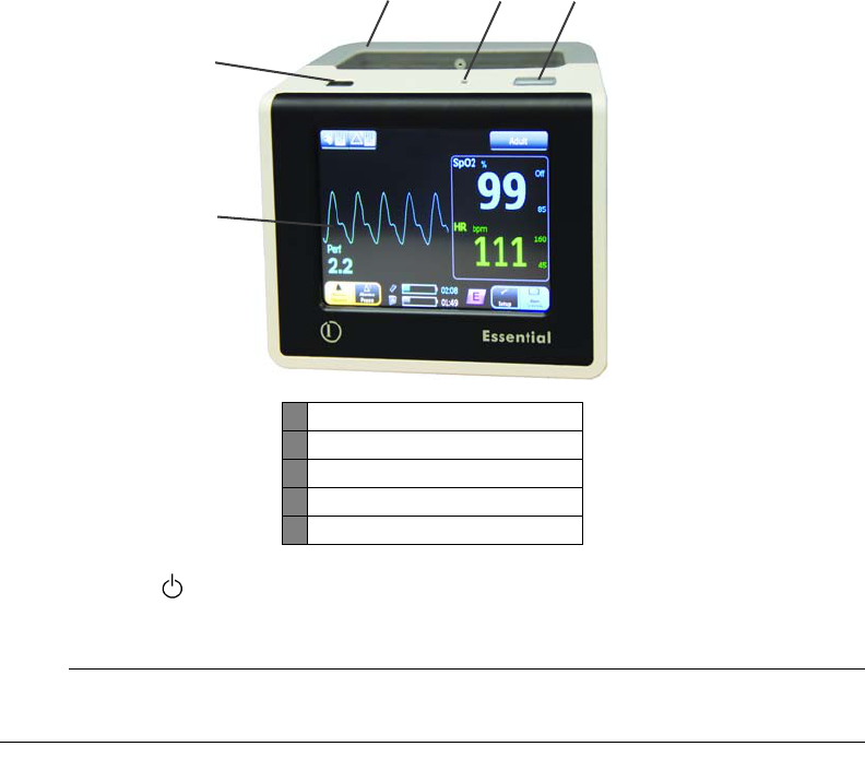
Monitor Overview
Themonitorisanintegrateddevicethathousescommunication,display,processingandpower
technologies(includingthetransceiversandantennas).Themonitorhasthefollowinguser
features:
CAUTION
Whenusingthemonitor,ensurethatyourviewofthedisplaypanelremainsunobstructed.
8ConnectthepoweradaptertotheDCinlet.
Observethepower(PWR)indicatorand
verifythatpowerisapplied:
• Green=DCpowerisconnected.
•None=Nopowerisconnectedoran
errorwasdetected.(Ensurethatthe
poweradapterisproperlyconnected
totheACoutlet.)
9Allowbothbatteriestofullycharge,as
indicatedbythechargeindicators:
• Green=Chargingcomplete
• Yellow=Batterycharging
•None=Nobatteryisinstalledoran
errorwasdetected.
10 DisconnectthepoweradapterfromtheDCinlet.
11 Removethemodulebatteryfromthechargingbay.
12 Insertthemodulebatteryintothemodule;seeInstallingthe
modulebattery,above.
13 Insertthemainbatteryintothemonitor;seeInstallingthemain
battery,above.Thiscompletestheprocedure.
24Chapter2:GettingStarted989803173791 Rev 0.6
1.Powerswitch()‐Controlspowertothemonitor,wherepressingtheswitchformorethan
0.5secondsturnspoweron,andpressingtheswitchformorethan1secondturnspoweroff.
NOTE
Ifcommunicationshavenotbeendetectedfor15minutes,themonitorwillautomaticallyturnoff.
2.Handle‐Providesportabilityandhousestheantennas.
3.Speaker‐Providesaudiblepromptsandalarmindications,atamaximumvolumeofupto85
dB;seeSoundMenuinChapter3fordetails.
4.Alarmlight‐Providesa360degreevisualalertforalarmconditions,glowingyelloworred,
dependingupontheconditiondetected;seeManagingAlarmsinChapter4fordetails.
5.Displaypanel‐Providesvisualinformationandistheall‐touchinterfaceforoperation,control
andsetupofthemonitor.
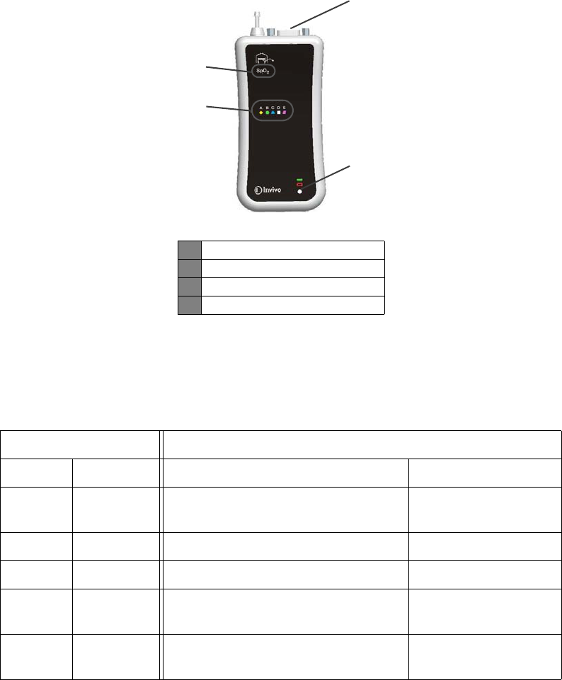
Wireless SpO2 Module Overview
Thewirelesspulseoximetry(WSpO2)moduleprovidesthepatient’sreadings,asdetectedsignals
areconvertedthentransmittedforprocessinganddisplay.Themodulehasthefollowinguser
features:
1Powerswitch
2Handle
3Speaker
4Alarmlight
5Displaypanel
5
23 4
1
989803173791 Rev 0.6Chapter2:GettingStarted 25
1.Networkselectionbutton‐Selectsthenetworksettingofthemodule.
2.Sensorconnector‐ConnectsthemoduletotheSpO2QuickConnectsensor.
3.Statusindicator‐Indicatesthepowerandcommunicationconditionsofthemodule:
4.Networkicons‐Indicatethewirelessnetworkdesignatedformodulecommunications,where
theilluminatedicondenotesthecurrentnetwork.
Assigning the Module Network
Themodulecommunicatesthroughabidirectional2.4GHzspread‐spectrumlink,whichis
automaticallyestablisheduponmonitorpower‐up.Thewirelessnetworkcanbechangedas
neededtocomplywiththerequirementsofyouroperatingenvironment,butshouldalways
1Networkselectionbutton
2Sensorconnector
3Statusindicator
4Networkicons
StatusindicatorMeaning
Color State PowerCommunication
None Not
applicable
Thebatteryisnotinstalledoritlacks
sufficientchargetopowerthemodule. Notapplicable
Green Flashing Batterypowergood Notcommunicating
Green Solid Batterypowergood Goodcommunications
Red Flashing Lowbatterycondition
(lessthat45minutesremain) Notcommunicating
Red Solid Lowbatterycondition
(lessthat45minutesremain) Goodcommunications
2
3
1
4
26Chapter2:GettingStarted989803173791 Rev 0.6
matchthesettingassignedtothemonitor;seeNetworkMenuinChapter3formonitorsetup
details.
Thewirelessnetworkforthemoduleisindicatedbyitsilluminatedicon,whilethecurrently
assignednetworkforthemonitorisindicatedbythenetworkbuttononthedisplaypanel.
CAUTION
Forsystemcommunications,themonitorandmodulemusthavethesamenetworksetting.
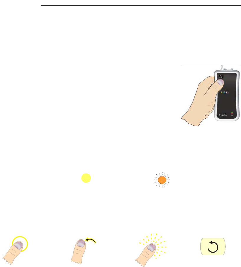
Changing the Module Network Setting
Thewirelessnetworkforthemoduleischangedviaitsnetwork
selectionbutton,locatedbeneaththeoverlay,inthefrontupper
leftcornerofthedevice.(Aslightbumpcanbefeltwhenyoupassa
fingeroverthebutton.)
Whenselectinganetworkforthemodule,placethemoduleona
flatsteadysurface,orholditasshownintheillustration,anduse
yourthumbtopressthenetworkselectionbutton.
Beforestartingtheprocedure,takenoteoftheseconventionsthat
areusedtoexplaintheprocess:
•Intheprocedurebelow,thefollowingsymbolsareusedtoconveythestateofthenetwork
icononawirelessmodule.
•Intheprocedurebelow,thefollowingillustrationsareusedtoconveyactionsconcerning
theuseofthenetworkselectionbutton:
Iconilluminated Iconflashing
Pressthe
button
Releasethe
button
Pressandhold
thebutton
Repeatas
desired
989803173791 Rev 0.6Chapter2:GettingStarted 27
NOTE
Anypartoftheabovesequencenotcompletedwillcausethemoduletoreverttothenetwork
previouslyset30secondsafterthenetworkselectionbuttonwaslastreleased.
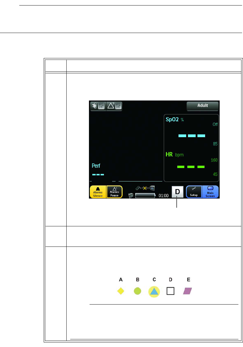
Toassignthewirelessmoduletothemonitor’snetworkfollowthesesteps:
Step Action
1 Identifythenetworksettingofthemonitor,asindicatedbythe
networkbutton.
2 Removethemodulebatteryfromthemodule;seeModuleBattery,
above.
3Installthemodulebattery.Thenetworkiconswillflashbrieflyand
thenthecurrentnetworkiconwillilluminate(forexample,
NetworkCintheillustrationbelow).
NOTE
Dependinguponyourmodule,thenetworkiconsmayhaveletteror
numericdesignators;and,thoughtheseexamplesshowletter
designators,theprocessisthesamefornumericdesignators.
Network button
28Chapter2:GettingStarted989803173791 Rev 0.6
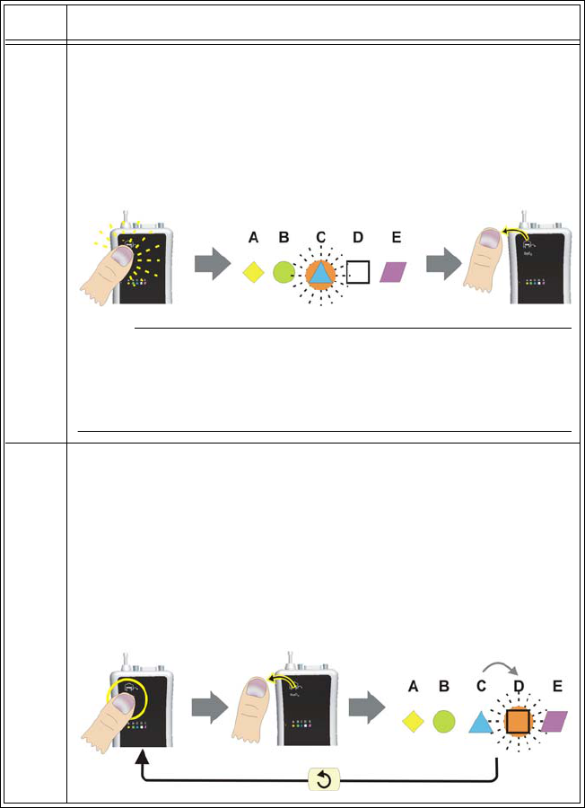
4Setthenetworkofthemoduletothesamenetworkasthemonitor
(seeStep1).Enterthenetworkchangemode.Afterthecurrent
networkiconhasbeenilluminated(andwithin15secondsfrom
modulepower‐up)pressandholdthenetworkselectionbutton
untilthecurrentnetworkiconbeginsflashingrapidly.Thenrelease
thenetworkselectionbutton.
NOTE
Ifthenetworkchangesequenceisnotstartedwithin15seconds
afterthemodulehasbeenturnedon,anetworkchangewillnotbe
allowed.Youmustcyclemodulepowerandrestartthesequence.
5Changingthenetwork,pressthebuttonagainuntiltheiconstops
flashing,thenreleasethebutton.Whenyoudothis,thenext
networkiconinthesequencewillblinkrapidly.(Inotherwords,if
themodulewasoriginallyusingnetwork“C,”nowthe“D”iconwill
beflashing.)Repeatthissequenceofpressingandreleasingthe
buttonuntiltheiconofthenetworkyoupreferisrapidlyflashing.If
youpassthedesirednetwork,simplycontinuepressingand
releasingthebuttonuntilthedesirednetworkisflashingagain.
Step Action
989803173791 Rev 0.6Chapter2:GettingStarted 29
Initial System Power-Up
Toapplypowertothesystemfollowthesesteps:
Step Action
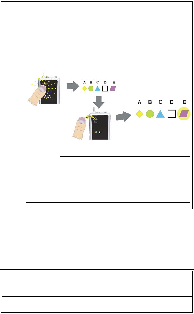
6Whenyoureachthedesirednetwork,pressandholdthebuttonfor
approximately5secondstolockandsavethenewnetwork.The
selectednetwork'siconwillturnoffwhilethebuttonisdepressed.
Thenitwillilluminate(notblink)whenthenewnetworksettingis
saved.Onceilluminated,releasethebutton.Themodulewillbegin
usingtheselectednetwork.
WAR NIN G
Ifthemessagebox,“WARNING!Multiplewirelessmodules
detectedonnetwork”isdisplayed,amodulenetworksetting
conflicthasbeendetectedbythemonitor.Beforeproceeding,for
properfunction,ensurethatonlyoneSpO2modulepernetwork
hasbeenassignedandisbeingused.
Step Action
1Ensurethatthemainbatteryisinstalledinthemonitor;seeMain
Battery,above.
2Ensurethatthemodulebatteryisinstalledthemodule;seeModule
Battery,above.
30Chapter2:GettingStarted989803173791 Rev 0.6
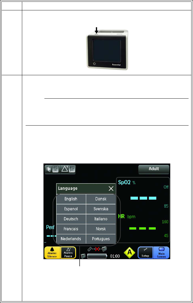
3Pressthepowerswitchforatleast0.5secondstoturnonthe
monitor.
4Thefirsttimethemonitoristurnedon,setthedisplaylanguagefor
thesystem:
NOTE
Itcantakeupto30secondsuntiltheboot‐upprocesshasfinished
andthemonitorbecomesready.
•IntheLanguagemenu,selectadisplaylanguagebytouching
acorrespondingLanguagebutton;seeNavigatingtheMenu
GroupsandControlsinChapter3fordetails.
(Ifnotsetinitially,theLanguagemenuwillcontinuetoappearat
subsequentpower‐upsuntiladisplaylanguageisselected.)
Step Action
Language buttons
989803173791 Rev 0.6Chapter2:GettingStarted 31
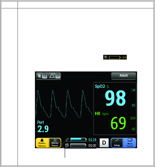
5Ensuresufficientmonitorpowerbycheckingthemainbattery
indicators,where:
•Graygaugeandtime=BatterypowerOK,timeremaining
fieldindicatesapproximateremainingchargeinhoursand
minutes.
• Flashingyellowgaugeandtime=Lowbatterypower(45
minutesorlesspowerremaining).
•NoBatteryCommunicationssymbol=No
communicationsbetweenthemonitorandthemainbattery.
Step Action
Main battery indicators
32Chapter2:GettingStarted989803173791 Rev 0.6
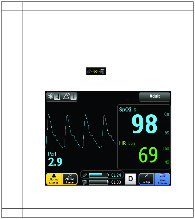
6Ensuresufficientmodulepowerandcommunicationswiththe
monitorbycheckingthemodulebatteryindicators,where:
•Bluegaugeandtime=BatterypowerOK(timeremaining
fieldindicatesapproximateremainingchargeinhoursand
minutes)andgoodcommunications.
• Flashingyellowbatterygaugeandtime=Lowbatterypower
(45minutesorlesspowerremaining).
•NoCommsymbol=Nocommunicationsbetween
themonitorandthemodule.
7VerifyproperoperationoftheSpO2parameter;seeChapter4.
Step Action
Module battery indicators
989803173791 Rev 0.6Chapter2:GettingStarted 33
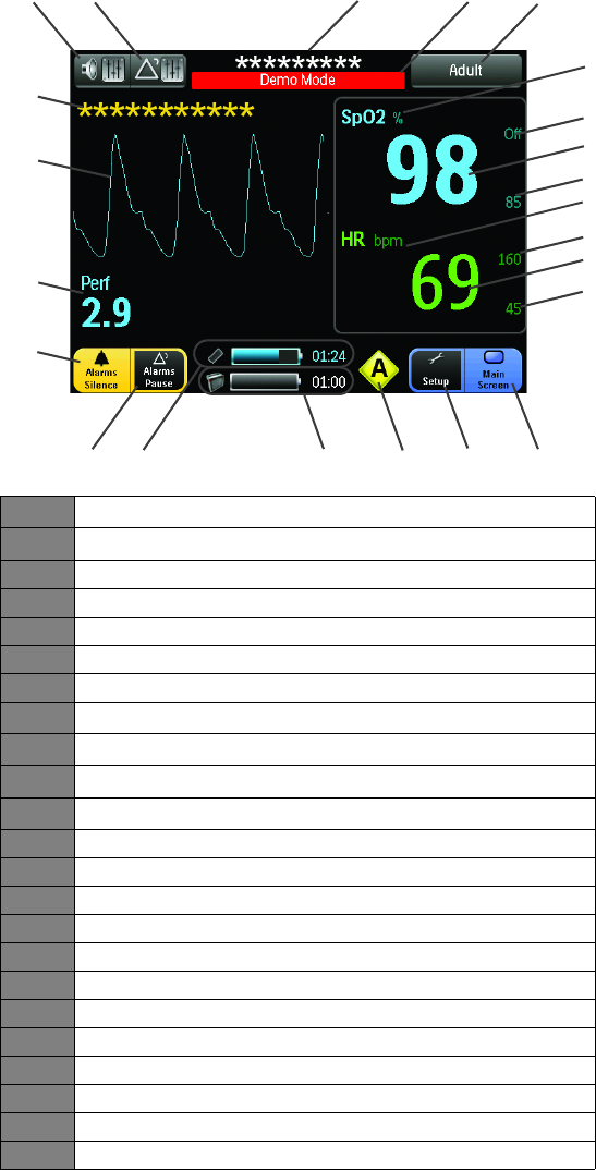
Display Panel Overview
Thedisplaypanelprovidesthefollowingfunctionsandinformation:
1SpO2waveform
2SpO2messagearea
3Speakerbutton
4Alarmsbutton
5Informationalmessagearea
6DemoModeindicator
7Patientcategorybutton
8SpO2parameteridentifier(inpercent)
9SpO2highalarmlimitindicator
10 SpO2vitalsignnumeric
11 SpO2lowalarmlimitindicator
12 Heartrate(HR)parameteridentifier(inbeatsperminute)
13 Heartratehighalarmlimitindicator
14 Heartratevitalsignnumeric
15 Heartratelowalarmlimitindicator
16 MainScreenbutton
17 Setupbutton
18 Networkbutton(dependentuponthenetworkselection)
19 Mainbatteryindicators
20 Modulebatteryindicators
21 AlarmsPausebutton
22 AlarmsSilencebutton
23 Perfusionindexvalue
*****
2
1
3456
16
7
8
9
10
11
12
13
15
17
18
19
20
14
21
22
23

34Chapter2:GettingStarted989803173791 Rev 0.6
NOTE
Displayupdateperiodistypically1second,uptoamaximumof30seconds.
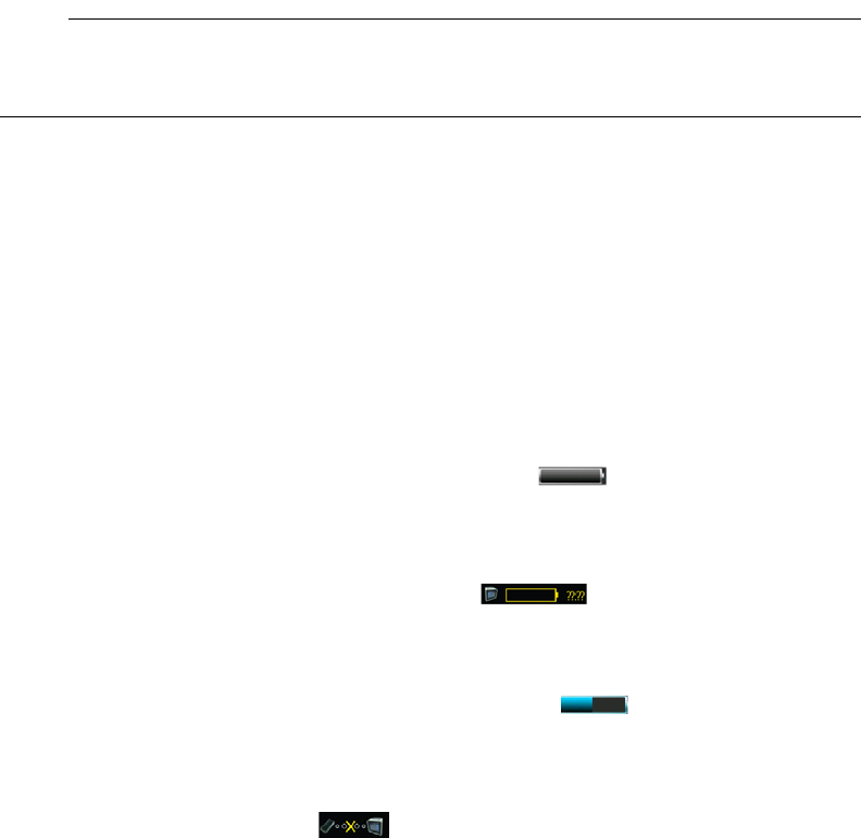
1.SpO2waveform‐Providestheplethysmographicwaveform,fixedacrossthescreenand
updatedwithanerasebar,wherearedwaveformindicatesanalarmcondition;seeWaveform
andVitalSignInformationinChapter4fordetails.
2.SpO2messagearea‐DisplaysSpO2relatedmessages.Foralisting,seeSystemMessagesin
Chapter4fordetails.
3.Speakerbutton‐Setsthevolumeforalarmtone,touchandpulsetones;seeSoundMenuin
Chapter3fordetails.
4.Alarmsbutton‐SetsthehighandlowalarmlimitsforSpO2andheartratealarms;seeSetup
MenuinChapter3fordetails.
5.Informationalmessagearea‐DisplaysalarmmessageswhentheAlarmsPausebuttonorthe
AlarmsSilencebuttonisselected.Foralisting,seeSystemMessagesinChapter4fordetails.
6.DemoModeindicator‐Indicatesthatthemonitorisoperatingindemonstrationmode;see
ServiceMenuinChapter3fordetails.
7.Patientcategorybutton‐Indicatesandallowschangestothepatientcategory;seePatient
MenuinChapter3fordetails.
8.Parameteridentifier‐IndicatestheSpO2parameterandunitofmeasurement.
9.SpO2highalarmlimitindicator‐Indicatesandallowschangestothehighlimitsettingforthe
SpO2alarm;seeAlarmLimitsMenuinChapter3fordetails.
10.SpO2vitalsignnumeric‐IndicatestheSpO2vitalsignofthepatient(givenasapercentage)
andallowschangestotheSpO2alarmlimits;seeWaveformandVitalSignInformationinChapter
4fordetails.
NOTE
Normalresponsetimeofthenumericsisapproximately10seconds;however,incaseofartifactor
poorsignalconditions,theupdateperiodcanbelonger.
11.SpO2lowalarmlimitindicator‐Indicatesandallowschangestothelowlimitsettingforthe
SpO2alarm;seeAlarmLimitsMenuinChapter3fordetails.
12.Parameteridentifier‐Indicatestheheartrateparameterandunitofmeasurement.
13.Heartratehighalarmlimitindicator‐Indicatesandallowschangestothehighlimitsetting
fortheheartratealarm;seeAlarmLimitsMenuinChapter3fordetails.
989803173791 Rev 0.6Chapter2:GettingStarted 35
14.Heartratevitalsignnumeric‐Indicatestheheartratevitalsignofthepatient(giveninbeats
perminute)andallowschangestotheheartratealarmlimits;seeWaveformandVitalSign
InformationinChapter4fordetailsfordetails.
NOTE
Normalresponsetimeofthenumericsisapproximately10seconds;however,incaseofartifactor
poorsignalconditions,theupdateperiodcanbelonger.
15.Heartratelowalarmlimitindicator‐Indicatesandallowschangestothelowlimitsettingfor
theheartratealarm;seeAlarmLimitsMenuinChapter3fordetails.
16.MainScreenbutton‐Closesanyopenmenus,returnsthedisplaytothenormaloperating
view,andcanlockthescreen;seeLockingandUnlockingtheScreeninChapter3fordetails.
17.Setupbutton‐OpenstheSetupmenu;seeSetupMenuinChapter3fordetails.
18.Networkbutton‐Opensthenetworksetupmenu;seeNetworkMenuinChapter3for
details.
19.Mainbatteryindicators:
•Displaystheremainingmainbatterypowerasagaugeandatimeremaining
counter(formattedinhours:minutes).Whenlessthanforty‐five(45)minutesremain,the
timewillflashinyellowandanalarmwillbedeclared;seeManagingAlarmsinChapter4
fordetails.
•Flashes
theNoBatteryCommunicationssymbolifcommunicationsarenot
established,orhavebeenlost,betweenthemonitorandthemainbattery.
20.Modulebatteryindicators:
•Displaystheremainingmodulebatterypowerasagaugeandatimeremaining
counter(formattedinhours:minutes).Whenlessthanforty‐five(45)minutesremain,the
timewillflashinyellowandanalarmwillbedeclared;seeManagingAlarmsinChapter4
fordetails.
•FlashestheNoCommsymbolifcommunicationsarenotestablished,orhavebeen
lost,betweenthemonitorandthemodule;alsoseeNoDataAvailableIndicationin
Chapter4fordetails.
21.AlarmsPausebutton‐Allowsyoutotemporarilydeactivatealarmfunctions,whereduring
deactivationa2minutetimer,flashinginred,willcountdownintheinformationalmessagearea;
seeManagingAlarmsinChapter4fordetails.
22.AlarmsSilencebutton‐Allowsyoutomutethealarmsoundandturnoffthealarmlight
duringanalarm(thoughindicationswillcontinuetoappearintheinformationalmessagearea,
andthealarmingnumericwillcontinuetoflash).Anewalarmwillcausereactivationofalarm
functions.Whenselected,the“AlarmsSilenced”message,flashinginred,willbedisplayedinthe
informationalmessagearea;seeManagingAlarmsinChapter4fordetails.
23.Perf‐Istheperfusionindex,anumericvaluefortheportionofthemeasuredsignalcaused
byarterialpulsation;seeWaveformandVitalSignInformationinChapter4fordetails.
36Chapter2:GettingStarted989803173791 Rev 0.6
989803173791 Rev 0.6Chapter3:PreparationforUse37
Chapter 3: Preparation for Use
TheEssentialMRIPatientMonitor(Model865353)providestheflexibilityneededtoperform
standardSpO2monitoring,whileallowingyoutocustomizeoperationstofityourneeds.
Warning
WAR NIN G
Alwaysverifypropercommunicationsbetweenthemoduleandmonitorpriortopatientuse.
CAUTIONS
•Avoidtheuseofcellularphonesorotherradio‐frequencytransmittersintheproximityof
anoperatingsystem.
•AminorbutnoticeabledegradationinthewirelessSpO2radiocommunicationswilloccur
inthepresenceofhigh‐poweredradios.
Using the Monitor
ObserveallwarningsandcautionswhenusingtheEssentialMRIPatientMonitor(Model
865353).
Warning
WAR NIN G
KeeptheEssentialdisplayoutoftheMRsystemboreandavoidcontactwiththepatient’sbare
skinwhiletheMRIscanisrunning.Thedeviceiselectronicandsusceptibletoexcessiveheating
fromtheMRIscanRFonlyifplacedinsidetheboreoftheMRsystemduringthatscan.Failure
todosomayresultinpatientinjury.
Warning
WAR NIN G
DonotuseortakethepoweradapterinsidetheMRsystemroom.Thedeviceismagneticand
willbepulledintotheMRsystem.Thedeviceisintendedforusewiththemainbatteryandthe
modulebatteryonlywhenoutsidetheMRsystemroom.
38Chapter3:PreparationforUse989803173791 Rev 0.6
System Parameters
TheEssentialMRIPatientMonitor(Model865353)facilitatesprocessinganddisplayofthe
plethysmographicwaveform,andtheassociatednumericvaluesandalarmsfortheoxygen
saturationofarterialbloodandthederivedheartrate.Allpatientinformationisprovidedonthe
displaypanel.
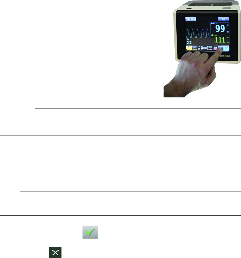
Navigating the Menu Groups and Controls
ThemenugroupsandcontrolsfortheEssentialMRIPatient
Monitor(Model865353)areaccessedandnavigatedby
touchingtheactiveareasonthetouchscreen.
Touchinganactivebuttonorindicatorwithyourfingerora
passiveobject(suchasastylus)willcausethesystemto
produceatouchtoneandopenthatmenuorselectthat
option,settingorvalue.(Notethatsimultaneouslytouching
twoormoreareasofthescreenmayproduceunpredictable
results.)
Toguardagainstaccidentalchanges,alockingfeatureallows
youtoprotectthemonitorsettings.
CAUTION
Neverusesharpobjectsonthedisplaypanelorapplyunnecessarypressuretothedisplaypanel,
asactioncanresultinscreendamageorfailure.
Controlling Menu Changes
Dependinguponthemenu,thesebuttonscontrolchangesmadetotheoptionsandsettings:
NOTE
Ifamenuisopen,delayingselectionofanoptionforlongerthan30secondsclosesthemenu.
•ConfirmandClosebutton:Touchtosavechangesandclosethemenu.
•Closebutton:Touchtodiscardchangesthatrequireconfirmationandclosethe
menu.(Ortouchanotherbutton.)
989803173791 Rev 0.6Chapter3:PreparationforUse39
•MainScreenbutton:Touchtocloseanopenmenu(andsaveanychanges‐
exceptthosethatrequireconfirmation)andreturntothenormaloperatingview.
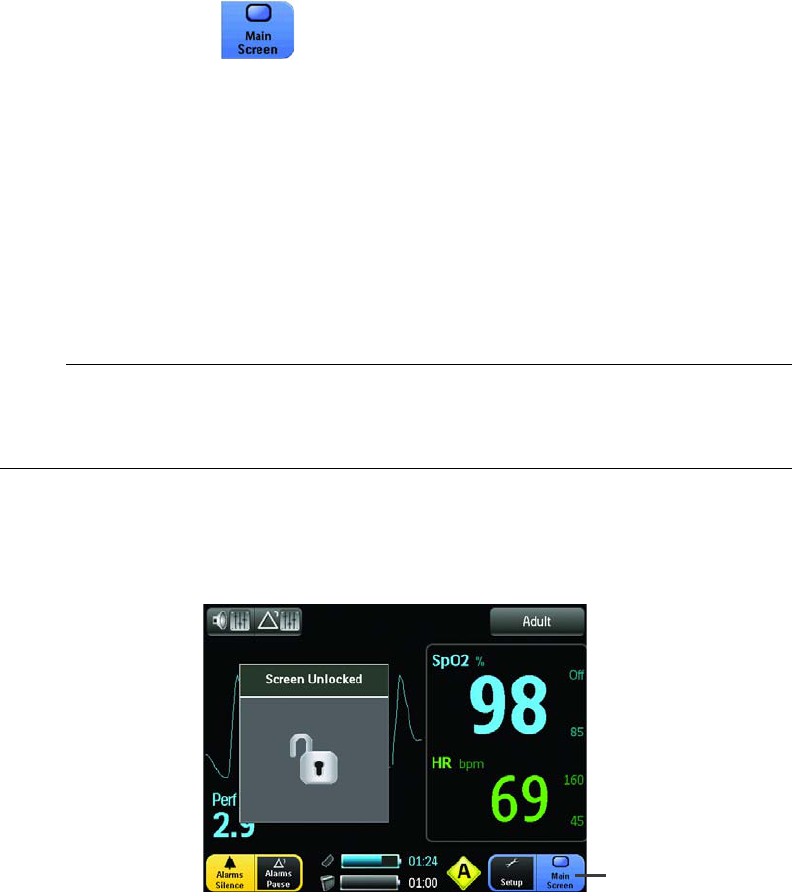
Locking and Unlocking the Screen
Thetouchscreencanbelockedtoprotectagainstaccidentalchangestothesetuporalarm
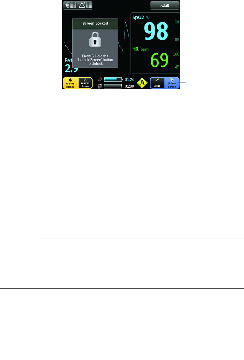
controls,whileallowingmonitoringfunctionstocontinue.Whenlocked,thetouchscreen
functionswillbeinaccessible,asdenotedbythe“ScreenLocked”messagewhichwillappearfor
about2.5secondsafterabuttonorindicatoristouched.Torestoreoperationtoalockedscreen,
pressandholdtheUnlockScreenbuttonforabout3seconds.Lockingandunlockingmethodsare
describedbelow.
NOTE
TheMainScreenbuttonisdynamic,changingtoreflectthecurrentstateofthedisplaywhere
“MainScreen”indicatesanunlockedconditionand“UnlockScreen”indicatesalockedcondition.
Tolockthescreen:
TouchtheMainScreenbuttonforabout3seconds.
Tounlockthescreen:
TouchtheUnlockScreenbuttonforabout3seconds.
Main Screen button
40Chapter3:PreparationforUse989803173791 Rev 0.6
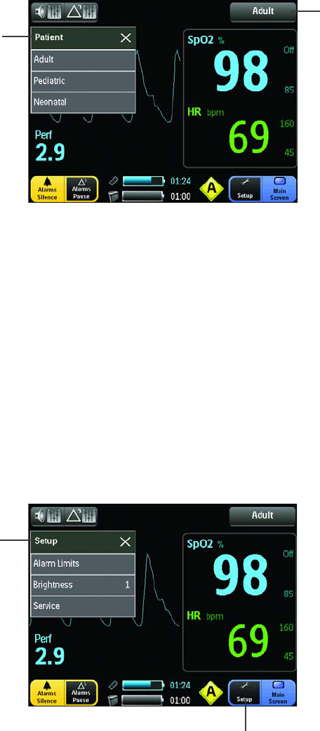
Patient Menu
ThePatientmenuallowsyoutoselectthepatientcategory.
Determiningtheappropriatepatientcategory
Eachsafetyagencyrecognizesthatthepatientcategorydescriptionscanbearbitraryandthat
thefollowingpatientfactorsaremoreaccurateindeterminingtheappropriatemethodof
patientmonitoringandtreatment:
•Weight
•Bodysize
•Limbcircumference
• Physiologicaldevelopment
•Neurological
development
• Neuromuscularcoordination
CAUTION
Theremaybeoccasionswhenaparticularpatientcategoryisnotsuitableforitsapparent
categorizationbasedonlyonage.Inthesecases,aclinicaldecisionshallbemadetouseanother
patientcategoryormeasurementtechnique.Theclinicaldecisionshallbebasedonallofthe
factorslistedinDeterminingtheappropriatepatientcategory(above)toensurethebestpossible
andmosttimelymeasurementacquisitions.
NOTES
•Thepatientcategorybuttonisdynamic,changingtoreflectthecurrentpatientcategory.
•Alarmlimitdefaultsettingsareappliedwheneverthepatientcategoryischanged,and
previouslychangedalarmsettingsforacertainpatientcategorywillbelost;seeAlarm
LimitsMenu(below)fordetails.
Unlock Screen button
989803173791 Rev 0.6Chapter3:PreparationforUse41
ToenterthePatientmenu:
TouchthePatientcategorybutton.
Thefollowingoptionsareavailable:
•Adult:Allowsyoutosetthemonitoringfunctionsforadultpatients.
•Pediatric:Allowsyoutosetthemonitoringfunctionsforpediatricpatients.
•Neonatal:Allowsyoutosetthemonitoringfunctionsforneonatalpatients.
Setup Menu
TheSetupmenuoptionsconfigurethealarmlimits,adjustthebrightnessofthedisplaypaneland
accesstheservicefunctions.
ToentertheSetupmenu:
TouchtheSetupbutton.
Thefollowingoptionsareavailable:
Patient menu
Patient category
button
Setup button
Setup menu
42Chapter3:PreparationforUse989803173791 Rev 0.6
•AlarmLimits:AllowsyoutoaccesstheAlarmLimitsmenu(seebelow).
•Brightness:Allowsyoutosetthedesiredintensityofthedisplay,where:
–3(Brightest)
–2(Bright)
–1(Normal)
NOTE
BrightnessoptionshigherthantheNormalsettingwillreducebatteryruntime.
•Service:AllowsyoutoaccesstheServicemenu(seebelow).
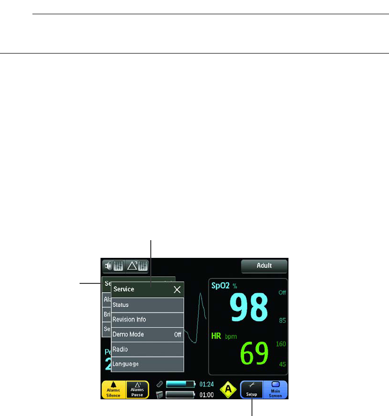
Service Menu
TheServicemenuallowsyoutoexaminethestatusofthehardwareandsoftwarerevisionlevels,
andtosetthelanguagedisplayedbythemonitor.Otheroptionsremainreservedforuseby
qualifiedserviceproviders,asnotedbelow.
ToentertheServicemenu:
TouchtheSetupbuttonandthenService.
Thefollowingoptionsareavailable:
•Status:AllowsyoutochecktheRealTimeClock,andtodisplaythecommunicationstatus
ofthemoduleandthemainbattery.
Setup menu
Setup button
Service menu

989803173791 Rev 0.6Chapter3:PreparationforUse43
•RevisionInfo:Allowsyoutoexaminethefirmwareandsoftwarelevelofthebootloader,
applicationandpowerprograms.
•DemoMode:Allowssystemoperationstobesimulated;seetheservicemanualfordetails.
NOTE
Thecorrectpasswordisrequiredforaccess:12151.
Warning
WAR NIN G
TheEssentialMRIPatientMonitor(Model865353)isequippedwithasimulationmodethat
displayscomputergenerateddatafortrainingpurposes.Asasafetyfeature,a“DemoMode”
messageisdisplayedwhileinsimulationmode.Donotattachapatienttothesystemwhenin
simulationmodeanddonotactivatesimulationmodewhenapatientisconnectedtothe
system.Thesystemwillnotmonitorpatientswhileinthesimulationmode.Failuretoproperly
monitorthepatientwillresult.Toexitsimulationmode,turnoffDemoModeusingthemenu,
orpoweroffthemonitor,orremovethebattery.
•Radio:Allowsaserviceprovidertochangetheradioandtotestradiopower;seethe
servicemanualfordetails.
NOTE
Thecorrectpasswordisrequiredforaccess.
•Language:Allowsyoutosetthelanguageusedtodisplaymenus,messagesandinterface
items,wherethefollowingoptionsareavailable:
– English
–Espanol
–Deutsch
– Francais
–Nederlands
–Dansk
–Svenska
– Italiano
–Norsk
–Portugues
44Chapter3:PreparationforUse989803173791 Rev 0.6
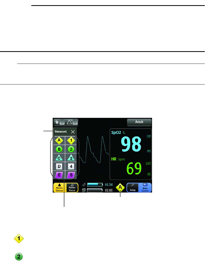
Network Menu
TheNetworkmenuallowsyoutosetthenetworkusedbythemonitorto
communicatewiththe
WSpO
2
module.Forpropercommunications,themonitorandmodulemustbelinkedonthesame
network.Foreaseofidentification,
networkselectionbuttonshaveuniqueshapes,designators
andcolors.
(Tochangethemodule’snetworksetting,see
AssigningtheModuleNetwork
in
Chapter2
.)
Warning
WAR NIN G
Ifthemessagebox,“WARNING!MULTIPLEWIRELESSMODULESDETECTEDONNETWORK”is
displayed,recheckthedesiredconfigurationofthemoduleandmonitor.Inenvironments
wheremultiplesystemsarebeingused,youmustbeawareofeachsystem’snetworksetting.
Operatingmultiplesystemsonthesamenetwork(orwithanincorrectnetworksetting)will
interferewithcommunications,andincorrectpatientvitalsignsinformationmaybeobtained
anddisplayedasaresult.Beforeproceeding,youmustresolvetheconflictingassignments.
NOTE
Thenetworkbuttonisdynamic,changingtoreflectthecurrentnetworksetting.
ToentertheNetworkmenu:
TouchtheNetworkbutton.
ThefollowingoptionsareavailablebypressingtheassociatedNetworkselectionbutton:
•
(Network1):
Allowsyoutos
et
systemcommunicationsforwirelessnetwork1
(compatibility
withaPrecessMRIPatientMonitorandmodule,Model3160‐Blueversion)
.
•(Network2):
Allowsyoutos
et
systemcommunicationsforwirelessnetwork2
(compatibility
withaPrecessMRIPatientMonitorandmodule,Model3160‐Blueversion).
Network menu
Network button
Network selection buttons
989803173791 Rev 0.6Chapter3:PreparationforUse45
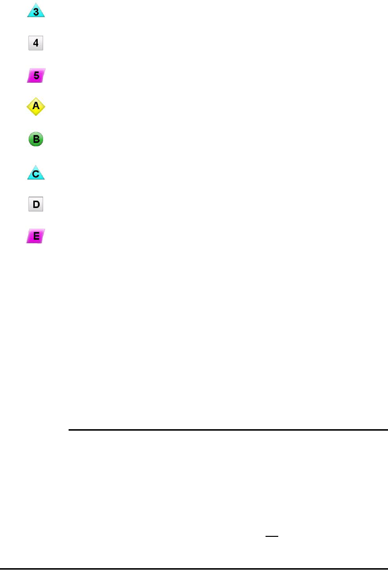
•(Network3):
Allowsyoutos
et
systemcommunicationsforwirelessnetwork3
(compatibility
withaPrecessMRIPatientMonitorandmodule,Model3160‐Blueversion)
.
•(Network4):
Allowsyoutos
et
systemcommunicationsforwirelessnetwork4
(compatibility
withaPrecessMRIPatientMonitorandmodule,Model3160‐Blueversion)
.
•(Network5):
Allowsyoutos
et
systemcommunicationsforwirelessnetwork5
(compatibility
withaPrecessMRIPatientMonitorandmodule,Model3160‐Blueversion)
.
•(NetworkA):
Allowsyoutos
et
systemcommunicationsforwirelessnetworkA
(compatibility
withanExpressionMRIPatientMonitorandmodule,Model865214)
.
•(NetworkB):
Allowsyoutos
et
systemcommunicationsforwirelessnetworkB
(compatibility
withanExpressionMRIPatientMonitorandmodule,Model865214)
.
•(NetworkC):
Allowsyoutos
et
systemcommunicationsforwirelessnetworkC
(compatibility
withanExpressionMRIPatientMonitorandmodule,Model865214)
.
•(NetworkD):
Allowsyoutos
et
systemcommunicationsforwirelessnetworkD
(compatibility
withanExpressionMRIPatientMonitorandmodule,Model865214)
.
•(NetworkE):
Allowsyoutos
et
systemcommunicationsforwirelessnetworkE
(compatibility
withanExpressionMRIPatientMonitorandmodule,Model865214)
.
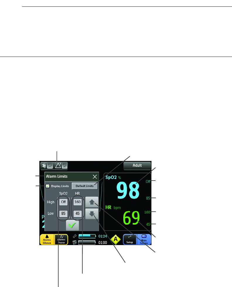
Alarm Limits Menu
TheAlarmLimitsmenuallowsyoutosetlimitsfortheSpO2andHR(heartrate)alarms,andto
controlthepresenceofthesesettingsonthedisplay
.Duringpatientmonitoringw
henavitalsign
hasviolatedanalarmlimit,ahighpriorityalarmisdeclared;seeManagingAlarmsinChapter4
fordetails.
WARNINGS
•Alwaysrespondpromptlytoanyalarmcondition.
• Settingthealarmlimitstoextremevaluescanrenderthealarmmonitoringuseless.A
potentialhazardcanexistifdifferentalarmmonitoringsettingsareusedforthesameor
similarequipmentinanysinglepatientcareunit.
• AlarmsgeneratedbytheEssentialMRIPatientMonitor(Model865353)willnot
synchronizewithotherpatientmonitoringsystems.
•Alarmlimitscanbesettoawiderangeofvalues,includingOff.Itistheresponsibilityof
theoperatorofthesystemtoensurethatalarmlimitvaluesappropriateforeachpatient
areestablishedandset.
46Chapter3:PreparationforUse989803173791 Rev 0.6
NOTES
•Thesystemautomaticallypreventscrossoverofthe
lowandhigh
alarmlimitsettings.
•Alarmlimitsettingchangesaresavedwhenpoweristurnedofforwhenchangingthe
battery.
•Whenthepatientcategoryischanged,factorydefaultalarmlimitsettingsareused.
ToentertheAlarmLimitsmenu:
•TouchtheAlarmsbutton.
AlarmLimitscanalsobeaccessedby:
–TouchingtheSpO2orHRvitalsignnumeric,
–Touchingaspecificalarmlimitindicator(fordirectaccesstothatsetting),or
–TouchingtheSetupbuttonandthenAlarmLimits.
Thefollowingoptionsareavailable:
•SpO2AlarmLimitsbuttons:Indicatesthecurrentsettingandallowsyoutosetthelimits
fortheSpO2alarm,adjustedbytouchingthebutton(HighorLow)followedbythe
incrementordecrementbutton.
Alarms button
Increment button
Decrement button
Default Limits button
Display Limits button
HR Alarm Limits buttons
HR vital sign numeric
SpO2 vital sign numeric
Alarm Limits menu SpO2 high alarm limit indicator
SpO2 low alarm limit indicator
HR high alarm limit indicator
HR low alarm limit indicator
SpO2 Alarm Limits buttons

989803173791 Rev 0.6Chapter3:PreparationforUse47
•HRAlarmLimitsbuttons:Indicatesthecurrentsettingandallowsyoutosetthelimitsfor
theHR(heartrate)alarm,adjustedbytouchingthebutton(HighorLow)followedbythe
incrementordecrementbutton.
•Decrementbutton:AllowsyoutodecreaseanAlarmLimitssetting,wheretouchingitonce
decreasesthecountbyoneandholdingitdecreasesthecountcontinuously.
•Incrementbutton:AllowsyoutoincreaseanAlarmLimitssetting,wheretouchingitonce
increasesthecountbyoneandholdingitincreasesthecountcontinuously.
•DefaultLimitsbutton:Allowsyoutoautomaticallychangethelowandhighalarmlimits
forbothparameterstothedefaultsettings(seethetablesbelow).
•DisplayLimitsbutton:Allowsyoutocontrolthepresenceofthehighandlowalarmlimit
indicatorsforSpO2andHR,whereacheckedboxdisplaystheindicators.
•SpO2vitalsignnumeric:IndicatestheSpO2vitalsignofthepatient(givenasapercentage)
andallowsyoutochangetotheSpO2alarmlimits,wheretouchingitopenstheAlarm
Limitsmenu.
•HRvitalsignnumeric:Indicatestheheartratevitalsignofthepatient(giveninbeatsper
minute)andallowsyoutochangetotheheartratealarmlimits,wheretouchingitopens
theAlarmLimitsmenu.
•SpO2highalarmlimitindicator:Indicatesandallowsdirectchangestothehighlimit
settingfortheSpO2alarm,wheretouchingitopenstheAlarmLimitsmenu.
•SpO2lowalarmlimitindicator:Indicatesandallowsdirectchangestothelowlimitsetting
fortheSpO2alarm,wheretouchingitopenstheAlarmLimitsmenu.
•HRhighalarmlimitindicator:Indicatesandallowsdirectchangestothehighlimitsetting
fortheheartratealarm,wheretouchingitopenstheAlarmLimitsmenu.
•HRlowalarmlimitindicator:Indicatesandallowsdirectchangestothelowlimitsetting
fortheheartratealarm,wheretouchingitopenstheAlarmLimitsmenu.
NeonatalAlarmLimits
VitalSign
Parameter Unit LowLimitHighLimit
MIN MAX Default MIN MAX Default
SpO2Percent 50 99 90 70 99 Off
HR BPM 30249 90 60 249 210
PediatricAlarmLimits
VitalSign
Parameter Unit LowLimitHighLimit
MIN MAX Default MIN MAX Default
SpO2Percent 50 99 90 70 99 Off
HR BPM 30249 75 60 249 160
48Chapter3:PreparationforUse989803173791 Rev 0.6
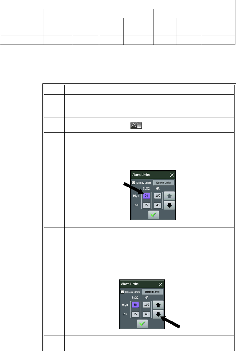
Tochangeanalarmsetting,followthestepsbelow:
AdultAlarmLimits
VitalSign
Parameter Unit LowLimitHighLimit
MIN MAX Default MIN MAX Default
SpO2Percent 50 99 85 70 99 Off
HR BPM 30249 45 60 249 160
Step Action
1
Ifachangeinthepatientcategoryisneeded,touchthePatient
categorybuttonthenmakethatchange;otherwise,proceedto
Step2.
2TouchtheAlarmsbutton.
3TouchthehighorthelowAlarmLimitsbuttonfortheparameter.
(Thetouchtonewillsoundandthebuttonwillbehighlighted.)
TheexamplebelowfollowsaSpO2highalarmlimitchange.
4Touchthedecrementortheincrementbuttonuntilthedesired
settingisreached,asdisplayedinthehighlightedAlarmLimits
button.
Forexample,thedecrementbuttonwastouchedtwice,resultingin
ahighalarmlimitof98.
5 RepeatSteps2and3toadjustadditionalalarmlimits.
989803173791 Rev 0.6Chapter3:PreparationforUse49
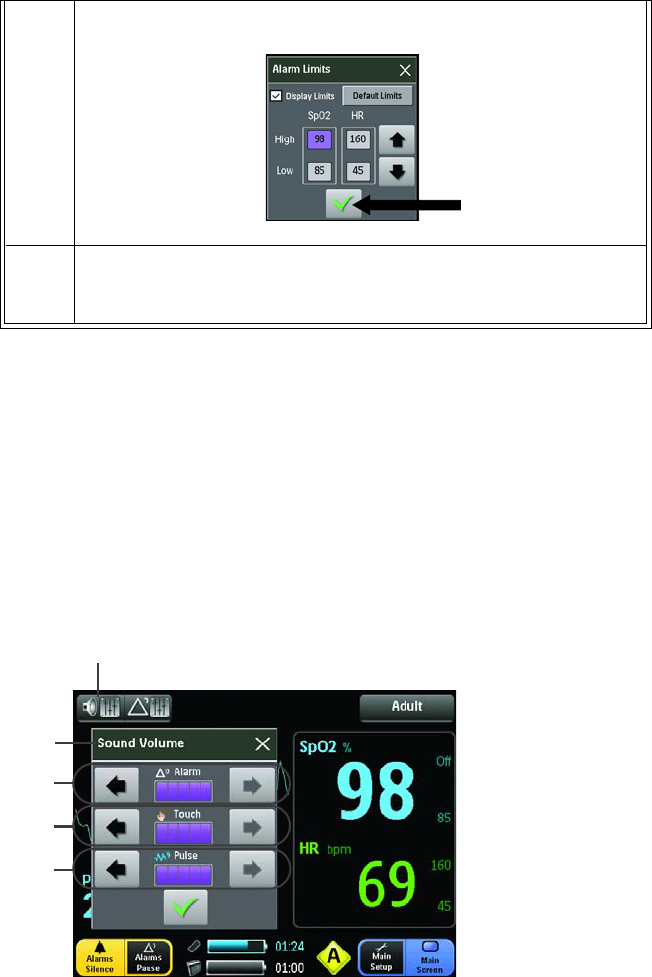
Sound Menu
TheSoundMenuallowsyoutoadjustthevolumelevelofthealarm,touchandpulsetones
producedbythemonitor.
ToentertheSoundmenu:
TouchtheSpeakerbutton.
Thefollowingoptionsareavailable:
•Alarmvolumebuttons:Setsthevolume(rangeis1–5)ofthetonegeneratedduringan
alarmcondition,wheretouchingthedecrementbutton(left)lowersthevolumeor
touchingtheincrement(right)buttonincreasesthevolume.
6Touchtheconfirmandclosebuttontosaveyourchanges.
7IfDisplayLimitsareenabled,thealarmsetting(s)willbeindicated
bythehighandlowalarmlimitindicators.(Thiscompletesthe
procedure.)
Speaker button
Sound menu
Alarm volume buttons
Touch volume buttons
Pulse volume buttons

50Chapter3:PreparationforUse989803173791 Rev 0.6
Warning
WAR NIN G
Adjustableforsuitabilitytovariousclinicalenvironments,thealarmvolumecanbeturnedlow
butnevercompletelyoff.Alwaysensurethatthealarmvolumesettingisappropriateforeach
patient.Whenyouusethesystem,alwaysverifythatthealarmtonecanbeheardabovethe
ambientnoiselevel.BesuretheminimumalarmvolumesettingisstillaudibleduringMRI
scanningbecauseinsomeenvironmentsaparticularsettingisbarelyaudible.Donotrely
exclusivelyontheaudiblealarmsystemforpatentmonitoring.Adjustmentofthealarm
volumetoalowlevelduringpatientmonitoringmayresultinpatientdanger.Rememberthe
mostreliablemethodofpatientmonitoringcombinesclosepersonalsurveillancewithcorrect
operationofmonitoringequipment.
•Touchvolumebuttons:Setsthevolume(rangeis0–5)ofthetonegeneratedwhenan
activeareaofthedisplaypanelistouched,wheretouchingthedecrementbutton(left)
lowersthevolumeortouchingtheincrement(right)buttonincreasesthevolume.
•Pulsevolumebuttons:Setsthevolume(rangeis0–5)ofthetonegeneratedwhenapulse
isdetected,wheretouchingthedecrementbutton(left)lowersthevolumeortouchingthe
increment(right)buttonincreasesthevolume.

989803173791 Rev 0.6Chapter4:MonitoringSpO251
Chapter 4: Monitoring SpO2
Thepulseoximetryfeatureusesamotion‐tolerantsignalprocessingalgorithmbasedonFourier
ArtifactSuppressionTechnology(FAST)toprovideoxygenatedhemoglobinmeasurementsanda
pulserate,specifically:
•Oxygensaturationofarterialblood(SpO2):Thepercentageofoxygenatedhemoglobinin
relationtothesumofoxyhemoglobinanddeoxyhemoglobin(functionalarterialoxygen
saturation).
•Plethysmographicwaveform:Avisualindicationofthepatient’spulsatilebloodflow.
•Heartrate:Thenumberofdetectedpulsationsperminute.
•Perfusionindexvalue:Anumericvalueforthepulsatileportionofthemeasuredsignal
causedbyarterialpulsation.
SpO2 Sensor and Wireless SpO2 Module
TheSpO2sensorandwirelessSpO2(WSpO2)modulemaybeusedintheMRsystembore,
althoughthemodulemustnotbeplacedwithintheMRIfieldofview(FOV).Invivo‐specifiedfiber
opticSpO2sensorsandtheWSpO2modulearedesignedforuseintheMRenvironment.Useonly
thespecifiedfiberopticSpO2sensors;seeAccessoriesinChapter1foralisting.
WAR NIN G
ConnectingSpO2sensorsotherthanthosespecifiedbyInvivointotheWSpO2modulecan
causeinaccurateSpO2readingsordamagethemodule.
CAUTIONS
•Ifdropped,theWSpO2modulemustbeverifiedforcorrectoperationbeforeuse.
•Guardagainsttheaccidentalingressofliquidintothemodule,asmeasurementsmadeby
thedevicecanbeadverselyaffected.
52Chapter4:MonitoringSpO2989803173791 Rev 0.6
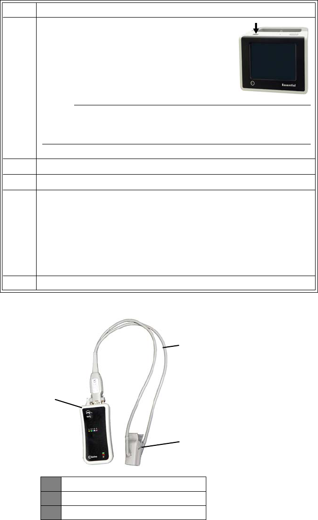
Connecting the Sensor and Attachments to the WSpO2 Module
VerifytheSpO2sensorandWSpO2modulestatusasfollows:
Step Action
1Pressthepowerswitchforabout0.5seconds.
Afterthemonitorison,checkthemain
batteryindicatorstoensuresufficientpower.
NOTE
UseAlarmsPausetotemporarilydisablethealarmfunctions.
2ConnectaSpO2sensortothemodule.
3Connecttheattachment(cliporgrip)totheSpO2sensor.
4Checkthestatusindicatoronthemoduletoverifysufficientpower
andgoodcommunicationsformonitoring:
• Solidgreen=Goodbatterypowerandgoodcommunications
• Flashinggreen=Goodbatterypowerbutnocommunications
• Solidred=Lowbatterypowerandgoodcommunications
• Flashingred=Lowbatterypowerbutnocommunications
5 ProceedtoApplyingandPositioningtheSpO2Sensor,below.
1WSpO2module
2SpO2sensor
3SpO2attachment(clipsorgrips)
1
2
3

989803173791 Rev 0.6Chapter4:MonitoringSpO253
Patient Preparation
ToprepareapatientforMRISpO2monitoring,followtheinstructionsbelow.
Applying and Positioning the SpO2 Sensor
ApplytheWSpO2attachmenttothepatientasfollows:
WARNINGS
• GENERALSENSORFIT:Ifasensoristooloose,itmightcompromisetheoptimal
alignmentordislocate.Ifthesensoristootight(forexample,iftheapplicationsiteistoo
largeorbecomeslargeduetoedema),excessivepressuremaybeappliedresultingin
venouscongestiondistalfromtheapplicationsite,whichcouldleadtointerstitial
edema,hypoxemia,tissuemalnutrition,andinaccuratemeasurements.Skinirritations
mayoccurasaresultofthesensorbeingattachedtoonelocationfortoolong.
Periodicallyinspectthesensorapplicationsiteandchangetheapplicationsiteatleast
everyfourhours.Exercisecarewhenusingtapetosecurethesensor,asthestretch
memorypropertiesofmosttapescanapplyunintendedpressuretothesensorsite
easily.
•EXTREMITIESTOAVOID:Avoidplacingthesensoronextremitieswithanarterial
catheter,intravascularvenousinfusionline,orinflatedbloodpressurecuff.Failuretodo
somayresultininaccuratereadingsorfalsealarmindications.
NOTE
Atsystempower‐up,ifthemonitorhascommunicationwiththemodulebutthemodule
attachmentisnotconnectedtothepatient,noalarmwillbedeclared.
Step Action
1 FollowtheInstructionsforUseprovidedwiththeSpO2sensor,
adheringtoallwarningsandcautions,andchooseanapplication
site.
2Ifpresent,removeanycolorednailpolishfromtheapplicationsite.
3Applytheattachmenttothepatient.Theapplicationsiteshould
matchthesizeoftheattachmentused,sothatthesensordoesnot
falloffthesiteorapplyexcessivepressuretothesite(seethe
Warnings,below).
4EnsurethesensorisnotplacedwithintheMRIFieldofView(FOV).
5Checkthatthelightemitterandthephotodetectoraredirectly
oppositeeachother,asthelightmustpassthroughthepatient’s
tissuetothephotodetectorforproperoperation.
6 ProceedtoMeasuringSpO2,below.
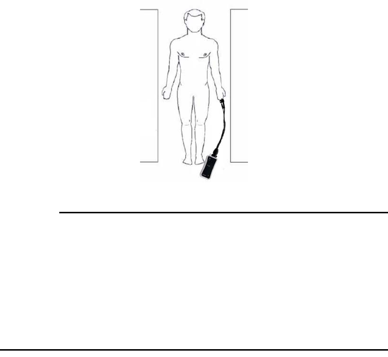
54Chapter4:MonitoringSpO2989803173791 Rev 0.6
Positioning the WSpO2 Module
Theselectedsite,sensorposition,attachmentconnection,andambientenvironmentallimpact
performanceandoperationduringSpO2monitoring.Toensurebestpossibleresultsfromthe
WSpO2moduleduringharshscansequences(withperipheralnervestimulation[PNS]levels
above80percent),observethefollowinggeneralplacementrules:
–PlacetheWSpO2moduleonornearthepatient,ascloseaspossibletotheboreiso‐
center(consideringthescantobeperformed),butkeepthewirelessmoduleoutside
theFOV.
–PlacetheWSpO2moduleascloseaspossibletotheboreopening.(Ifthemodulecan
beplacedoutsidethebore,positioningattheiso‐centerisnotnecessary.)
–PlacetheWSpO2moduleonacushionedsurfacetominimizetheMRvibrations.
WAR NIN G
IftheWSpO2moduleisincorrectlypositionedwhenusedwithintheMRsystemroom,the
followingfactorscancauseSpO2waveformdistortionandnumericinaccuracies:
•Fastmagneticfieldchanges,usuallyfoundbutnotlimitedtoscansequencesusingPNS
levelsabove80percent;
•SeverevibrationsinducedbyscansequencesusingPNSlevelsabove80percent;
•ThedistancefromtheMRboreopening;and,
•Thedistancefromtheboreiso‐centerinthex,y,orzdirections.
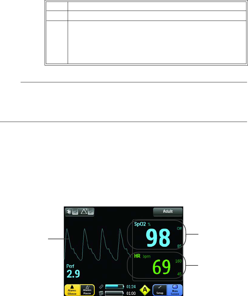
989803173791 Rev 0.6Chapter4:MonitoringSpO255
Measuring SpO2
TodisplayfunctionalSpO2values,followtheinstructionsbelow:
NOTE
Apulseoximetershouldbeconsideredanearlywarningdevice.Asatrendtowardspatient
deoxygenationisindicated,bloodsamplesmustbeanalyzedbyalaboratoryco‐oximeterto
understandthepatient’sconditioncompletely.
Waveform and Vital Sign Information
Thewaveformandvitalsignnumericdataprovidesimportantphysiologicalinformation,as
detailedinthetablebelow.
Step Action
1 Selectthepatientcategory(Adult,Pediatric,orNeonatal).
2Duringmeasurement,ensurethattheapplicationsite:
•hasapulsatileflow,ideallywithaperfusionindexvalue
above1.0;and,
•hasnotchangedinthickness(forexample,duetoedema)
causinganimpropersensorfit.
12
3
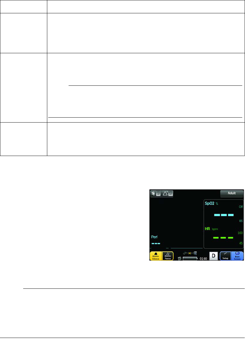
56Chapter4:MonitoringSpO2989803173791 Rev 0.6
No Data Available Indication
Undercertainconditions,thevitalsignnumericsand/or
theperfusionindexvaluemaybedisplayedas3dashes
(‐‐‐),whichmeansnodataiscurrentlyavailableforthe
parameter(s).Thiscanhappenforanyofthefollowing
reasons:
•Theparameterisinastart‐upstate;
•TheSpO2sensorisnotappliedtothepatient;
•Thereisnocommunicationwiththemodule;or
•Themeasurementisdistorted,thepulsetooweak
orthesignalinadequateinanyrespect.
NOTES
•Ifthesystemwasjustturnedonoriftheprobewasjustapplied,givethemonitora
momenttolockontothewirelesssignal.
•Ifthisconditionpersists,ensurethatthenetworksettingisthesameforthemoduleand
themonitor,andthatthecommunicationbetweenthedevicesisgood.
ItemNumber Explanation
1
TheSpO2(pleth)pulsatilewaveform,updatedfromlefttorightacrossthe
displaypanel.Ifthepulseisaboveaminimumlevel,theamplitudeofthe
waveformwillautomaticallybeadjustedforproperviewing.Ifyouneedan
indicationofchangeinpulsevolume,usetheperfusionindexvalue
describedinitem4.
2
TheSpO2numericisthepatient'sarterialoxygensaturationreading,given
asapercentage.Also,ifDisplayedLimitsaresettoon,theSpO2alarm
settingsareshowninthehighandlowalarmlimitindicators.
NOTE
AveragingtimeisfixedandmaybeoverriddenbyExpressionorPrecess
workflow.
3
TheHRnumericisthepatient’sheartrate,asderivedfromtheSpO2
measurement,giveninbeatsperminute.Also,ifDisplayedLimitsaresetto
on,theHRalarmsettingsareshowninthehighandlowalarmlimit
indicators.

989803173791 Rev 0.6Chapter4:MonitoringSpO257
Assessing Suspicious SpO2 Readings
Withneweralgorithms,suchasFAST‐SpO2,thecalculationofSpO2isnotdirectlylinkedtothe
correctdetectionofeachpulse.Whenthepulserateisveryloworastrongarrhythmiaispresent,
theSpO2/plethysmographypulseratemaydifferfromtheheartratecalculatedviaanECG.This
doesnotindicateaninaccurateSpO2value.IfyoudoubtthemeasuredSpO2,usethe
plethysmographywaveandperfusionindexvaluetoassessthesignalquality.
WARNINGS
•AlwaysshieldtheSpO2sensorfromextraneousincidentallightsources(forexample,
coverthesensorwithopaquematerial),assuchlightcancauseerroneousSpO2readings
orpulsedetectionerrors.
•SpO
2monitoringrequiresthedetectionofvalidpulsestocorrectlydetermineSpO2and
heartratevalues.AnyofthefollowingitemscanleadtoinaccuraciesoftheSpO2
readingsand/orprolongedmeasurementtime:Ambientlight(includingphotodynamic
therapy),physicalmovement(patientandimposedmotion),arrhythmiasand/orerratic
heartbeats,diagnostictesting,lowperfusion,electromagneticinterference,
electrosurgicalunits,dysfunctionalhemoglobin,intravasculardyes,presenceofdyesor
pigmentsattheapplicationsite,andinappropriatepositioningofthepulseoximeter
probe.Ifquestionablereadingsareobtained,checkthepatient’svitalsignsbyalternate
meansbeforeadministeringmedication.
•Sensormovement,ambientlight(especiallystrobelightsorflashinglights),or
electromagneticinterferencecangiveunexpectedintermittentreadingswhenthesensor
isnotattachedtoapatient.Bandageandgripsensordesignsareparticularlysensitiveto
minimalsensormovementthatmightoccurwhenthesensorisdangling,notattachedto
thepatient.Unappliedsensorsmaycausereadingstobedisplayedonthemonitor.To
avoidmisdiagnosis,verifysensorisappliedtopatientcorrectly.
Perfusion Index Value
TheperfusionindexvalueisanindicationofthepulsatileportionoftheSpO2signalcausedby
thepatient'sarterialbloodflow.ThisvaluecanbeusedasaqualityindicatoroftheSpO2
measurementfromthemodule.Thetablebelowprovidesgeneralguidelinesregardingthisindex
value,aswellasthecorrectiveactionsneededwhena“LowPerfusion”alarmisgenerated,
PerfusionIndexValue Meaning
Above1.0 Optimal–highqualityreadings
0.3to1.0 Acceptable–goodqualityreadings
Below0.3 Marginal–thepositionoftheattachmentshouldbeadjustedor
anothersiteshouldbeusedformeasurement.
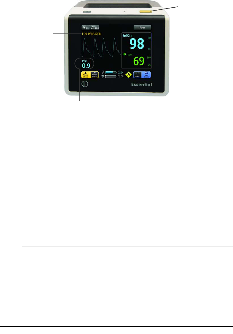
58Chapter4:MonitoringSpO2989803173791 Rev 0.6
Managing Alarms
AccesstoeveryparameteralarmisprovidedbytheAlarmsbutton(seeAlarmLimitsMenuin
Chapter3fordetails).Alarmlimitsmaybeturnedon,adjusted(manuallyorautomatically)or
turnedoffusingtheAlarmLimitsmenu.Thesystemgivesvisualalarmsignals(onthedisplay
panelandbythealarmlight)andaudiblesignals.
Alarm Types, Priorities and Indications
TheEssentialMRIPatientMonitor(Model865353)assignsdifferentprioritiesandindications
whenreportingalarms.Alarmsareassignedahighormediumprioritystatusbythesystem
accordingtothetypeofviolation:physiologicalortechnical.
NOTES
•Highpriorityalarmssoundlevelsrangefromatleast53dB(aminimumvolumesetting)to
84dB(maximumvolumesetting)in1mdistance.
•Mediumpriorityalarmssoundlevelsrangefromatleast49dB(aminimumvolumesetting)
to71dB(maximumvolumesetting)in1mdistance.
•Thedelaytimeofmakingvisualandaudiblealarmsavailablefromthealarmingequipment
totheremoteequipmentatthesignaloutputportislessthan1second.Inthecaseof
artifactorpoorsignalconditions,updatetimeofSpO2andHRnumericscantakeaslongas
30seconds.Alarmlimitviolationsarereportedasahighpriorityalarmwithin1second.
Perfusionindexvalue
Yellow alarm light
Message
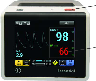
989803173791 Rev 0.6Chapter4:MonitoringSpO259
Physiological Alarm Violations
Physiologicalalarmsreceivethehighestpriorityreportingstatus.Aphysiologicalalarmisviolated
whenapatientparameter(SpO2orheartrate)exceedsthehighorlowsettingofthe
correspondingalarmlimit.Thereactionofthesystemtoaphysiologicalalarmdependsuponthe
settingsdescribedbelowandgenerallyasfollows:
a. Thealarmlightflashesred(seeillustrationbelow).
b. IfSpO2related,aredwaveformisdisplayed.
c. Thenumericoftheviolatedparameterflashesred.
d. Thehighpriorityalarmtonesounds‐‐atahighpitch‐‐5pulsetonesfollowedbya1
seconddelaythen5pulsetones,repeatingevery5seconds.
e. Thenumericcontinuestoflashwhiletheparameterviolatesitsalarmlimit,evenafter
thealarmtonehasbeenmutedbytouchingtheAlarmsSilencebutton.
f. Ifthenumericexceedsthehighestvaluethatcanbedisplayed,OVRwillbeindicated
intheparameternumeric.
g. Thenumericstopsflashingaftertheparameterreturnstowithinitsalarmlimits.
h. Thedisplayednumericoftheviolatedparameterflashesandtheaudiblealarm,once
silenced,willnotsoundagainuntilthealarmconditionhasbeencorrectedandre‐
violated.Onlyaseconddifferentparameteralarmwillcausethealarmsoundand
alarmlighttoreactivate.
Example,visualphysiologicalalarmindicators:
PhysiologicalalarmtestingcanbeperformedusingapatientSpO2simulatortoexceedan
individualalarmlimit.Alarmtestingcanalsobeperformedusingthemonitor’sDemomode
whereanindividualparameteralarmlimitcanbeadjusted‐‐ahighlimitsetbelowthesimulated
numericoralowlimitsetabovethesimulatednumeric(exceptSpO2)‐‐totriggeraphysiological
alarm.Ifaproblemwiththealarmtoneormessagesystemissuspected,thissystemmustbe
referredtoanInvivo‐authorizedservicepersonnelforevaluation.
Red vital sign numeric
Red alarm light
60Chapter4:MonitoringSpO2989803173791 Rev 0.6
Technical Alarm Violations
Technicalalarmsreceiveamediumpriorityreportingstatus.Atechnicalalarmisviolatedwhena
changeinsystemstatusoraproblemwiththehardwareorthemeasurementisdetected(for
example‐alowbattery,acommunicationsfailure,oraSpO2inoperativecondition).
NOTES
•Atsystempower‐up,ifthemonitordoesnothavecommunicationwiththemodule,a
mediumpriorityalarmwillbedeclared.
•Atmodulepower‐up,ifcommunicationwiththemodulebatteryislost,amediumpriority
alarmwillbedeclared.
•Ifthesystemlosescommunicationwiththemainbattery,amediumpriorityalarmwillbe
declared.
Thereactionofthesystemtoatechnicalalarmdependsuponspecificsystemoperationsand
generallyasfollows:
a. Thealarmlightflashesyellow(seeillustrationbelow).
b. Themediumpriorityalarmtonesounds‐‐atalowpitch‐‐3pulsetonesfollowedbya
10seconddelay,repeating.
c. Messagesaredisplayedinyellow(exceptforlowbatteryorcommunicationsfailure
conditions)toidentifythecauseofthealarm;seeSystemMessages,below,forthe
listing.
d. Ifalowbatteryconditionexists,thecorrespondingbatteryindicatorandtime
remainingcounterwillflashinyellow.
e. Ifacommunicationsfailureexists,thecorrespondingsymbolwillflashinyellow(the
NoCommsymbolformonitortomodulecommunications,ortheNoBattery
Communicationsymbolformonitortomainbatterycommunications).
f. Thealarmconditionstopsaftertheproblemiscorrectedorthesystemstatusreturns
toanormalcondition.
g. Themessageflashesandtheaudiblealarm,oncesilenced,willnotsoundagainuntil
thealarmconditionhasbeencorrectedandre‐violated.Onlyaseconddifferent
parameteralarmwillcausethealarmsoundandalarmlighttoreactivate.
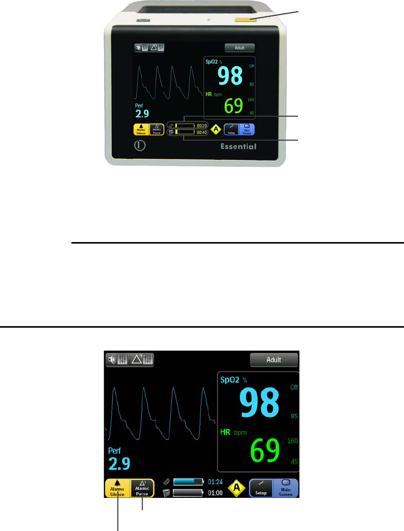
989803173791 Rev 0.6Chapter4:MonitoringSpO261
Example,visualtechnicalalarmindicators:
Alarm Controls
AlarmscanbecontrolledusingtheAlarmsSilencebuttonortheAlarmsPausebutton.
WARNINGS
•Whenalarmindicators(light,message,orsound)aregenerated,alwaysconfirmalarm
conditionswithclinicalobservationofthepatientbeforeadministeringinterventions.
Failuretodosomayresultininappropriateintervention.
•Oncethenumerichasexceededthealarmlimit,thedelaytoannouncingthealarm
conditionislessthan1second,andthetotalalarmdelayislessthan1second.
•AlarmsSilencebutton:Allowsyoutomutethealarmtoneandturnoffthealarmlight
duringanalarmcondition(althoughalarmindicationswillcontinuetobedisplayed).When
Yellow alarm light
Low battery, module
Low battery, monitor
Alarms Silence button
Alarms Pause button

62Chapter4:MonitoringSpO2989803173791 Rev 0.6
selected,the“AlarmsSilenced”message,flashinginred,willbedisplayedinthe
informationalmessagearea.Anewalarmconditionwillcausereactivationofthesound
andlightfunctions.
Warning
WAR NIN G
Anactivesilencedalarmmaynotbeaccompaniedbyan“ALARMSSILENCED”messageif
AlarmsPausehasbeenactivated,orifasubsequentadditionalalarmhasoccurredandwas
self‐corrected.
•AlarmsPausebutton:Allowsyoutotemporarilydeactivatethealarmfunctions(helpful,
forexample,whenpreppingapatientformonitoring).Whenselected,the“Alarms
Paused”messageanda2minutecountdowntimer,flashinginred,willbedisplayedinthe
informationalmessagearea.
NOTE
Alarmfunctionsarerestoredwhenthecountdowntimerreacheszero(0)orwhentheAlarms
Pausebuttonistouchedduringthecountdown.
System Messages
Thefollowingtablelistsmessagesthatcanbedisplayedbythesystemduringoperation,and
providesmeanings,probablecausesandrecommendedactions(ifneeded)forproblem
resolutions.Ifthemessagepersistsafterperformingtherecommendedaction(s),contactInvivo
TechnicalSupportorInvivo‐authorizedservicepersonnelforassistance.
Message Meaning ProbableCause RecommendedAction
AlarmsPaused Alarmsarepaused
untilthecountdown
timerreacheszero.
TheAlarmsPause
buttonwastouched.
Noactionrequired.Normalalarmmonitoring
functionwillresumeuponexpirationofthe
countdown(orimmediatelyifAlarmsPauseis
touchedagain.)
AlarmsSilenced Alarmshavebeen
silenced.
TheAlarmsSilence
buttonwastouched.
TouchtheAlarmsPausebuttontwiceto
returnnormalalarmmonitoringfunctions.
BadProbe Thesystemhas
detecteda
hardwarefailurein
thesensor.
TheSpO2sensoris
defective.
TryanotherSpO2sensor.
Erratic Erratic
measurementsare
beingproducedby
thesystem.
TheSpO2sensoris
notproperlyapplied
tothepatient,isnot
properlypositioned,
ortheprobeisfaulty.
•Checkthealignmentoftheprobe.
•Tryusingadifferentprobe.

989803173791 Rev 0.6Chapter4:MonitoringSpO263
HWFAIL SpO2hardware
failure.
Ahardwareorother
fatalerrorhas
occurredinsidethe
wirelessmoduleor
themonitor.
TryanotherWSpO2module.Ifthefailure
persists,immediatelyremovethesystemfrom
serviceandcontactInvivoforrepair,asthe
systemmustnotbeusedonanypatient
requiringSpO2measurement.
INTRFERNCE Thesignalqualityof
thelightchannelsis
inadequatefor
accuratesaturation
calculation.
Theprobelight
sourcemaynotbe
alignedwiththelight
receiver,orthe
probemaybepoorly
positioned.
•Checkthealignmentoftheprobe.
•Tryadifferentlimborsite.
•Tryusingadifferentprobe.
LOWPERFUSION Theperfusion
measuredislow
enoughtocause
possible
inaccuraciesinthe
reportedsaturation
value.
Thetissueatthesite
maybetooopaque
and/orthick.
Ifthesensorispositionedonafinger,check
thefingernailfornailpolish,orlongor
artificialfingernails.Removefingernailpolish
completely.Forartificialnails,tryanother
location(forexample,atoe).
NOPROBE TheWSpO2module
detectsthatno
probeisconnected.
TheSpO2probeis
notconnected(oris
notproperly
connected)tothe
module.
Checktheconnectionoftheprobetothe
WSpO2module.Ifconnectionappearssound,
tryanotherprobe.
NON‐PULSAT Non‐pulsatile
condition.
Checkthecondition
ofthepatient.
Thepatient’spulseis
tooweakforthe
systemtoreport
reliableSpO2
saturationandpulse
measurements.
•Checktheprobepositionandalignmenton
thepatient,thenre‐positionorre‐applyas
necessary.
•Tryadifferentlimborsite.
NOISE Patientmotionor
electrical
interferenceisbeing
experiencedbythe
SpO2system.
Excessivepatient
motionorelectrical
noise.
•Checkforpatientmotion,especiallyatthe
monitoredsite.
• Ensurethattheprobeispositionedsothat
thesensorsarenotexposedtoexcessive
levelsofambientlight.
PROBEOFF Thesystemdetects
thattheprobeisnot
appliedtothe
patient.
TheSpO2sensoris
notproperlyapplied
tothepatient.
Checkprobepositionandalignmentonthe
patient,thenrepositionorreapplyitas
necessary.
PULSE? TheSpO2‐derived
pulserateisoutside
thedetectable
range.
Theprobemaynot
beappliedoptimally
orthetissueatthe
appliedsitemaytoo
opaque.
•Checkthealignmentoftheprobe.
•Tryadifferentlimborsite.
Message Meaning ProbableCause RecommendedAction

64Chapter4:MonitoringSpO2989803173791 Rev 0.6
SEARCHING Thesystemis
searchingforagood
pulse.
Theprobewasjust
appliedtothe
patient,ortheprobe
hasshiftedposition
sincebeingapplied.
Iftheprobewasjustapplied,givethesystem
time(usuallylessthan20seconds)tolock
ontoagoodpulse;otherwise,checktheprobe
positionandre‐position.
WRONGPROBE Thesystemhas
detectedthatan
incorrectprobeis
connectedtothe
module.
Theprobeconnected
tothemoduleis
wrong.
AttachthecorrectSpO2sensortothemodule.
Message Meaning ProbableCause RecommendedAction
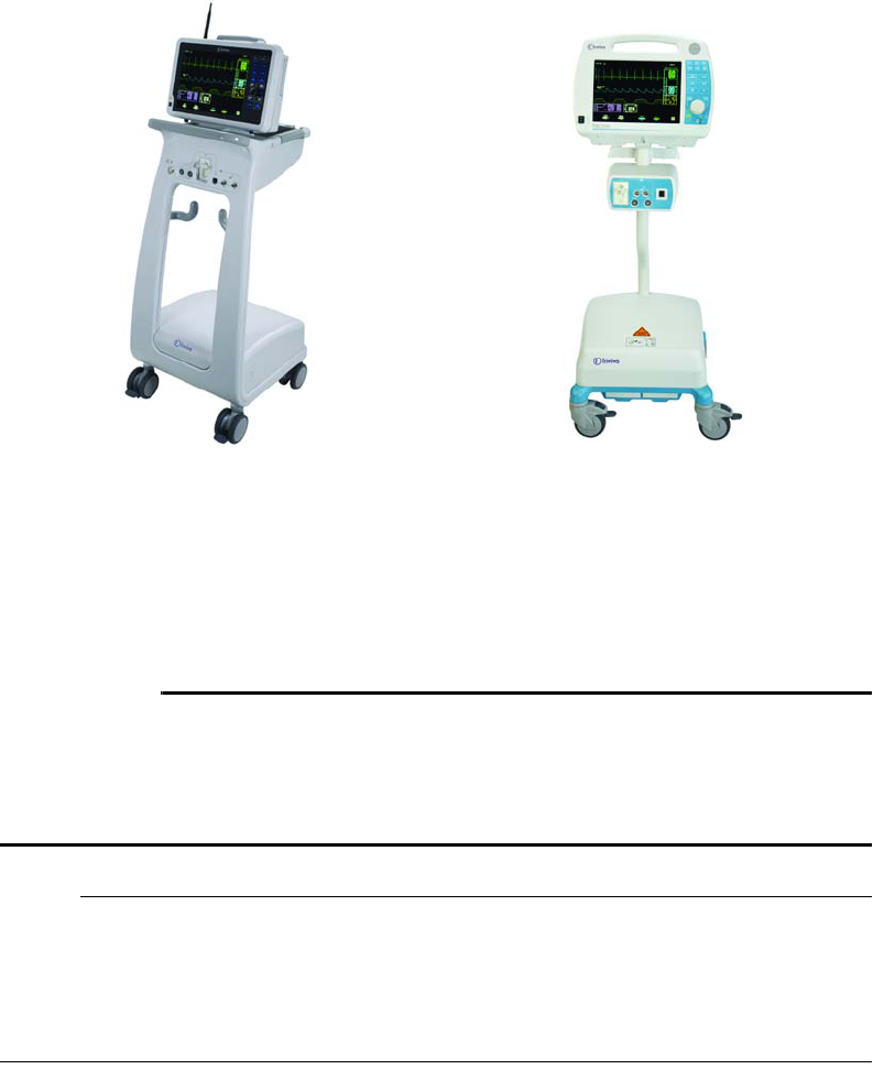
989803173791 Rev 0.6Chapter5:Workflow 65
Chapter 5: Workflow
TheEssentialMRIPatientMonitor(Model865353)canbeusedinconjunctionwiththe
Expression
MRIPatientMonitor(Model865214)andthePrecessMRIPatientMonitor(Model3160‐Blue
version)
toprovideseamlesspatientmonitoringfrominductiontoscanningtorecovery.
WhenusingtheEssentialwiththeseotherInvivoMRImonitors,observethefollowingwarnings
andnotes.
WARNINGS
•Alarmlimitsettingsdonottransferbetweenmonitoringsystemsandmaybedifferent,
soalwaysensurecorrectalarmlimitsettingswhenusingmultiplemonitoringsystems.
•AllSpO2modulesmustbeondifferentnetworks;otherwise,interference,orwrong
patientoralternatingpickupbetweenpatientscanoccur.
NOTES
•TheEssentialMRIPatientMonitor(Model865353)isnotcompatiblewiththeoriginal
PrecessWSpO2module.
•ThenumericsandwaveformaregeneratedbytheWSpO2module,andthereforeare
identicalregardlessofthemonitoringsystemused.
ExpressionMRIPatientMonitor
(Model865214)
PrecessMRIPatientMonitor
(Model3160‐Blueversion)
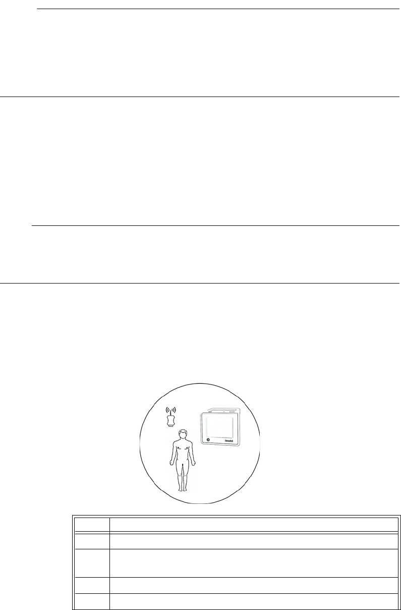
66Chapter5:Workflow989803173791 Rev 0.6
NOTES
•Toestablishpatientmonitoring,theEssentialmustbecommunicatingonthesamenetwork
asthemoduleandattachedtothepatient.
• Monitorsettings(forexample,patientcategory,alarmlimits,etc.)donottransferbetween
monitoringsystems,andalarmbehaviorremainslinkedtothealarmlimitsettingsandthe
detectednumerics.
Workflow Management
Thefollowingdiagramsillustratetypicalandalternateworkflowobjectiveswhenusingthe
EssentialasastandalonedeviceorwhenusingittogetherwithcompatibleInvivoMRImonitors.
NOTE
Thenetworksettingsandgroupingsusedbelowaregivenasexamplesonly;yourselectionsmay
differ.However,thenetworkconventions(A‐Eor1‐5)aswellasthegroupingofthesettings
(networkAversusB,1versus2,etc)shouldbeobserved.
WorkflowwhenusingtheEssentialasastandalonemonitorwithoneWSpO2module:
•Apatient,anMRinductionroom,anMRsystemroomandanMRrecoveryroom.
–TheEssentialandtheWSpO2modulearesettonetworkAornetwork1,depending
uponthemoduletype(ExpressionorPrecess‐Blueversion).
Step Action
1PrepthepatientintheMRinductionroom.
2TurnontheEssentialandtheWSpO2module.Botharesetto
networkA(or1).
3Verifysufficientpowerandgoodcommunications.
4ApplytheSpO2sensortothepatient.
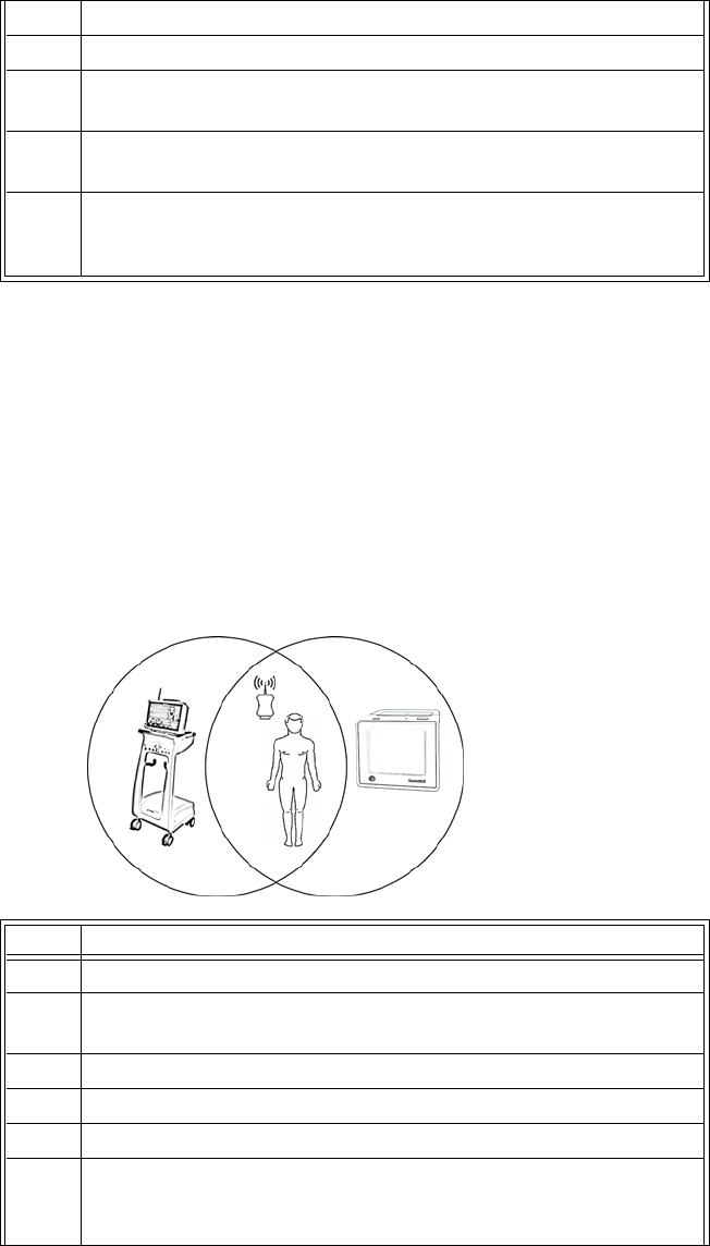
989803173791 Rev 0.6Chapter5:Workflow 67
WorkflowwhenusingtheEssentialwithanExpression(oraPrecess‐Blueversion)systemand
oneWSpO2module:
•Apatient,anMRinductionroom,anMRsystemroomwithanExpression(oraPrecess)
andanMRrecoveryroom.
–TheEssential,theExpressionandtheWSpO2modulearesettonetworkA(orifusing
aPrecess‐Blueversion,network1).
5Setthepatientcategoryandverifypulsatileflow.
6TransportthepatientwiththeEssentialintotheMRsystemroom.
7Scanthepatient,monitoringSpO2withtheEssentialthroughthe
controlroomwindow.
8TransportthepatientwiththeEssentialandtheWSpO2module
intotheMRrecoveryroom.
9 TransitionthepatientintotheMRrecoveryroomtobedside
monitoring,ifneeded,thentaketheEssentialandtheWSpO2
moduleintotheMRinductionroomforthenextpatient.
Step Action
1PrepthepatientintheMRinductionroom.
2TurnontheEssentialandtheWSpO2module.Botharesetto
networkA(or1ifusingaPrecess).
3Verifysufficientpowerandgoodcommunications.
4ApplytheSpO2sensortothepatient.
5Setthepatientcategoryandverifypulsatileflow.
6TransportthepatientwiththeEssentialintotheMRsystemroom
forscanning,wheretheExpressionissettonetworkA(orifusinga
Precess,network1).
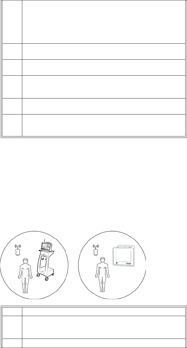
68Chapter5:Workflow989803173791 Rev 0.6
WorkflowwhenusingtheEssentialwithanExpression(oraPrecess‐Blueversion)systemand
twoWSpO2modules:
•Twopatientssimultaneously,anMRinductionroom,anMRroomwithanExpression(ora
Precess)andanMRrecoveryroom.
–TheExpressionandaWSpO2modulearesettonetworkA(orforPrecess,network1).
–TheEssentialandaWSpO2modulearesettonetworkB(orforPrecess,network2).
7IntheMRsystemroom,connectthepatienttotheadditionalvital
signsmeasurementsthenadjustthealarmlimits,patientcategory,
andothersettingsasneededontheExpression(orPrecess).As
soonastheWSpO2moduleiswithinrange,theExpression[or
Precess]willbeginmonitoringSpO2automaticallyandyoucanturn
offtheEssential.
8Scanthepatient,usingtheExpression(orPrecess)inthecontrol
room.
9TurnontheEssentialtomonitorSpO2.(TheEssentialwillnowbegin
tomonitorSpO2automatically.)
10 InordertotransportthepatienttotheMRrecoveryroom,
disconnectthepatientfromallvitalsignmeasurementsexcept
SpO2providedbyExpression(orPrecess).
11 TransportthepatientwiththeEssentialandtheWSpO2module
intotheMRrecoveryroom.
12 Ifneeded,transitionthepatientintheMRrecoveryroomto
bedsidemonitoring.TaketheEssentialandtheWSpO2moduleinto
theMRinductionroomforthenextpatient.
Step Action
1One(current)patientisintheMRsystemroom,wherean
ExpressionandWSpO2modulearesettonetworkA(orifusinga
Precess,network1).
2Prepthesecond(new)patientintheMRinductionroom.

989803173791 Rev 0.6Chapter5:Workflow 69
3TurnontheEssentialandtheWSpO2module.Botharesetto
networkB(orifusingaPrecess,network2).
4Verifysufficientpowerandgoodcommunications.
5ApplytheSpO2sensortothenewpatient.
6Setthepatientcategoryandverifypulsatileflow.
7Whenthescanofthecurrentpatienthasfinished,transportthe
newpatientwiththeEssentialandtheWSpO2moduleintotheMR
systemroom.
8FromthecurrentpatientintheMRsystemroom,disconnectthe
sensorfromtheSpO2QuickConnectattachment(grip).
NOTE
PresstheAlarmsSilencekeytotemporarilydisablethealarm
functions.
9FromthenewpatientintheMRsystemroom,disconnectthe
sensorfromtheSpO2QuickConnectattachment(grip).
NOTE
TouchtheAlarmsPausebuttontotemporarilydisablethealarm
functions.
10 IntheMRsystemroom,connectthenewpatienttotheadditional
vitalmeasurementsontheExpression,stillonnetworkA(orthe
Precess,stillonnetwork1).
11 TransportthecurrentpatientwiththeEssentialandtheWSpO2
module,stillonnetworkB(orforthePrecessstillonnetwork2)
intotheMRrecoveryroom.
12 Ifneeded,transitionthecurrentpatientintheMRrecoveryroom
tobedsidemonitoring.TaketheEssentialandtheWSpO2module
intotheMRinductionroomforthenextpatient.
13 Scannewthepatient,usingtheExpressionDCU(orthePrecess
CRD)inthecontrolroom.

70Chapter5:Workflow989803173791 Rev 0.6
WorkflowwhenusingtheEssentialwithaPrecess(Blueversion)system,twoWSpO2modules
andtwoECGmodules:
•Twopatientssimultaneously,anMRinductionroom,anMRroomwithaPrecessandan
MRrecoveryroom.
–ThePrecess,aWSpO2moduleandanECGmodulearesettonetwork1.
–TheEssential,aWSpO2moduleandanECGmodulearesettonetwork2.
Step Action
1One(current)patientisintheMRsystemroom,whereaPrecess,a
WSpO2moduleandaECGmodulearesettonetwork1.
2Prepthesecond(new)patientintheMRinductionroom.
3TurnontheEssential,theWSpO2moduleandtheECGmodule.All
aresettonetwork2.
4Verifysufficientpowerandgoodcommunications.(TheECG
modulecannotnotbecheckedatthispoint.)
5ApplytheSpO2sensorandtheECGleadstothenewpatient.
6Setthepatientcategoryandverifypulsatileflow.
7Whenthescanofthecurrentpatienthasfinished,transportthe
newpatientwiththeEssential,theWSpO2moduleandtheECG
moduleintotheMRsystemroom.
8IntheMRsystemroom,onthePrecessdisplaypanel,pressthe
MONITORSETUPkey.TurnthecontrolknobtoNETWORK,pressthe
knobandselectNetwork2.
NOTE
PresstheAlarmsSilencekeytotemporarilydisablethealarm
functions.
9IntheMRsystemroom,connectthenewpatienttotheadditional
vitalmeasurementsonthePrecess.Verifysufficientpowerand
goodcommunicationsforthemodules.

989803173791 Rev 0.6Chapter5:Workflow 71
10 Inthecontrolroom,onthePrecessCRDdisplaypanel,pressthe
MONITORSETUPkey.TurnthecontrolknobtoNETWORK,pressthe
knobandselectNetwork2.
11 OntheEssentialdisplaypanel,presstheNetworkbuttonthen
selectNetwork1.
NOTE
TouchtheAlarmsPausebuttontotemporarilydisablethealarm
functions.
12 VerifysufficientpowerandgoodcommunicationsfortheWSpO2
module.(TheECGmodulewillnotbeusedandcannotnotbe
checkedatthispoint.)
13 TransportthecurrentpatientwiththeEssential,theWSpO2
moduleandtheECGmoduleintotheMRrecoveryroom.
14 Ifneeded,transitionthecurrentpatientintheMRrecoveryroom
tobedsidemonitoring.TaketheEssentialtheWSpO2moduleand
theECGmoduleintotheMRinductionroomforthenextpatient.
15 Scannewthepatient,usingthePrecessCRDinthecontrolroom.
72Chapter5:Workflow989803173791 Rev 0.6

989803173791 Rev 0.6Chapter6:MaintenanceandRepair73
Chapter 6: Maintenance and Repair
MethodstokeeptheEssentialMRIPatientMonitor(Model865353)cleanandinproperworking
conditionarediscussedhere.
Maintenance
Cleaning
UseonlytheInvivoapprovedsubstancesandmethodslistedinthissectiontocleanordisinfect
theEssentialMRIPatientMonitor(Model865353).Warrantydoesnotcoverdamagecausedby
usingunapprovedsubstancesormethods.
Invivomakesnoclaimsregardingtheefficacyofthelistedchemicalsormethodsasameansfor
controllinginfection.Consultyourfacility'sInfectionControlOfficerorEpidemiologist.For
comprehensivedetailsoncleaningagentsandtheirefficacyreferto“GuidelinesforPreventionof
TransmissionofHumanImmunodeficiencyVirusandHepatitisBVirustoHealthCareandPublic‐
SafetyWorkers”issuedbytheU.S.DepartmentofHealthandHumanServices,PublicHealth
Service,CentersforDiseaseControl,February1989.Alsorefertoanypoliciesthatapplywithin
yourfacilityandcountry.
Cleaning the System
TheEssentialMRIPatientMonitor(Model865353)cannotbesterilized.Alwaysturnoffthe
systemtoperformcleaning.Donotimmerseanypartofthesysteminanyfluidorattemptto
cleanitwithliquidcleaningagents.Removedirtanddustfromthemonitorandthewireless
modulebywipingthemwithalint‐freecloth,moistenedwithwarmwater(40°C/104°F
maximum).Gentlywipeallsurfacestobecleanedbriefly(30secondsto1minute)asneededto
ensurepropercleaning.Stainscanberemovedbyscrubbingbrisklywiththemoistenedcloth.
Ifdisinfectionisrequired,useonlythedilutesolutionsofanyofthefollowingrecommended
liquidsurfacedisinfectants:
•CaviWipes
• Alcohol(70%)
• AntibacterialSoap(0.1%Triclosan)
WAR NIN G
Toavoiddamagetotheconnector,donotremovethebatterybeforeperforminganycleaning
ormaintenance.And,toavoidanelectricalhazard,neverimmerseanypartofthesystemin
anycleaningagentorattempttocleanitwithliquidcleaningagents.

74Chapter6:MaintenanceandRepair989803173791 Rev 0.6
CAUTIONS
•Avoidammonia‐based,phenol‐based,andacetone‐basedcleaners.Theywilldamagethe
systemsurfaces.
•Ifthesystembecomesaccidentallywetduringuse,discontinueoperationuntilallaffected
componentshavebeencleanedandpermittedtodrycompletely.ContactInvivoTechnical
Supportifadditionalinformationisrequired.
Cleaning the Accessories
Anyreusablepatientaccessoriesmustbecleanedaftereachuse.Disposablepatientaccessories
mustbediscardedandreplacedwithnewitems.Theaccessoriescannotbesterilized.
WAR NIN G
Single‐usedevices,asindicatedonthedevicepackaging,shouldbedisposedofafter useand
mustneverbereused.
CAUTION
Neverimmerseanaccessoryinanycleaningfluid.
Tocleanreusableaccessories(suchasSpO2sensorsandgrips),completethefollowingsteps:
CAUTION
Disinfecttheaccessoryasdeterminedbyyourfacility’spolicy.
Step Action
1 Removetheaccessoryfromuse.
2 Removedirtanddustfromtheaccessoryusingalint‐freecloth,
moistenedwithwarmwater(40CFmaximum)gentlywiping
allsurfacestobecleanedbriefly(30secondsto1minute)as
neededtoensurepropercleansing.Stainscanberemovedfrom
theaccessorybyscrubbingbrisklywiththemoistenedcloth.
3Inspecttheaccessoryforanycracks,holes,tears,cuts,etc.that
couldaffectoperationandreplaceasnecessary.
4Ifdisinfectionisrequired,useonlytherecommendedliquidsurface
disinfectants,unlessotherwisespecifiedintheaccessory’s
instructionsforuse.Recommendedsurfacedisinfectantsinclude
dilutesolutionsofanyofthefollowing:
•CaviWipes
• Alcohol(70%)
• AntibacterialSoap(0.1%Triclosan)

989803173791 Rev 0.6Chapter6:MaintenanceandRepair75
Repair
AllrepairsonproductsunderwarrantymustbeperformedbyInvivopersonneloranauthorized
InvivoServiceandRepairCenter.Unauthorizedrepairswillvoidthewarranty.
WAR NIN G
Ashockhazardexistsifthesystemisoperatedwithoutcovers.
IftheEssentialMRIPatientMonitor(Model865353)failstofunctionproperlyorrequires
maintenance,contactTechnicalSupport:
IntheUnitedStates:
1‐877‐INVIVO1
‐or‐
1‐877‐468‐4861
Internationally,pleasecontactyourKeyMarket.Foracurrentlisting,gotowww.invivocorp.com
CAUTIONS
•Norepairshouldeverbeundertakenorattemptedbyanyonenothavingathorough
knowledgeoftherepairofInvivopatientmonitoringsystems.Onlyreplacedamagedparts
withcomponentsmanufacturedorsoldbyInvivo(Philips).ContacttheTechnicalService
andRepairCenterfortechnicalassistanceandservice.
•Thisproduct,oranyofitsparts,mustnotberepairedotherthaninaccordancewith
writteninstructionsprovidedbyInvivo(Philips),oralteredwithoutpriorwrittenapproval.
Changesandmodificationstotheradioanditscomponentsnotexpresslyapprovedby
Invivo(Philips)canvoidyourauthoritytooperatethisequipmentunderFederal
CommunicationsCommission’srules.
•Theuserofthisproductshallhavethesoleresponsibilityforanymalfunctionwhichresults
fromimproperuse,faultymaintenance,improperrepair,damage,oralterationbyanyone
otherthanInvivo(Philips)oritsauthorizedservicepersonnel.
NOTE
Disposeofthesystemandpartsthereofaccordingtolocalregulations.
76Chapter6:MaintenanceandRepair989803173791 Rev 0.6

989803173791 Rev 0.6AppendixA:Specifications77
Appendix A: Specifications
General
PatientSafety
ConformstoULSTD60601‐1.CertifiedtoCAN/CSASTDC22.2No.601.1
Accordingtodegreeofprotectionagainstharmfulingressofwater:IPX2(equipmentisprotectedfromvertically
drippingliquid)
Thisequipmentcompliestothefollowinginternationalindustrystandardsforsafetyandperformance:
•IEC60601‐1,GeneralRequirementsforSafetyofMedicalElectricalEquipment
•IEC60601‐1‐2,GeneralRequirementsforSafety‐ElectromagneticCompatibility
•IEC60601‐1‐4,GeneralRequirementsforSafetyofProgrammableElectricalMedicalSystems
•IEC60601‐1‐8,GeneralRequirements,TestsandGuidanceforAlarmSystemsinMedicalElectrical
EquipmentandMedicalElectricalSystems
•ISO9919,ParticularRequirementsfortheBasicSafetyandEssentialPerformanceofPulseOximeter
EquipmentforMedicaluse
Whereappropriate,theequipmentcompliestoworldwidestandardsforsafetyandperformanceofeachsystem
feature,whenconsideringtheindicationsforusewithintheMRenvironment.
PowerRequirements
OperatingVoltageBatteryonly
Battery
Type Lithiumpolymer
OperationTimeMonitor:Approximateoperationtimeis8hours.
Module:Approximateoperationtimeis8hours.
ChargeTime Monitor:Timerequiredtorechargeafullydischargedbatteryis
approximately8hours.
Module:Timerequiredtorechargeafullydischargedbatteryis
approximately6hours.
Environment
OperatingTemperature 10°Cto40°C(50°Fto104°F)
StorageTemperatureBatteries:0°Cto40°C(32°Fto104°F)
System:‐25°Cto70°C(‐13to158°F)
Whenstoringbeyondthetemperaturerangesspecified,remove
thedesignatedcomponentandstoreitappropriately.
RelativeHumidity 15to90%,non‐condensing
TransportTemperature ‐25°Cto70°C(‐13to158°F)

78AppendixA:Specifications989803173791 Rev 0.6
DimensionsandWeights(Note:allmeasurementsmadeincludinghandle)
Height Monitor:6.1inches(155mm)
WirelessSpO2Module:5.5inches(13.9cm)
Width Monitor:6.9inches(175mm)
WirelessSpO2Module:2.5inches(6.4cm)
Depth Monitor:3.7inches(94mm)
WirelessSpO2Module:0.91inches(2.3cm)
Weight Monitor:3.3lbs(1.5Kg)
WirelessSpO2Module:5.2oz(147gm)
Display(LCD)
Type 640x480pixels,colorVGALiquidCrystalDisplaywith5‐Wire
touchscreen
ScreenSize 5.7inches(14.5cm)
SweepSpeed 25mm/secondgives2.7secondsofdisplay
WaveformDisplayMode FixedTrace,MovingEraseBar
DisplayedParameters
Alarms Highandlowlimitselectable
HeartRate DerivedfromSpO2
PulseOximeter Heartrate,pulsewaveform,percentsaturation,andperfusion
index
PulseOximeter
Pitchofpulsetoneismodulatedbysaturationvalue.
SaturationRange 0to100%
SaturationAccuracy ±3%at70to100%(Thespecifiedaccuracyistheroot‐mean
square(RMS)differencebetweenthemeasuredvaluesandthe
referencevalues)
PulseRange 30to250bpm
PulseAccuracy ±2%or1bpm,whicheverisgreater
WavelengthRange 500to1000nm:Informationaboutthewavelengthrangecanbe
especiallyusefultoclinicians(forinstance,whenphotodynamic
therapyisperformed.
EmittedLightEnergy <15mW:Informationaboutthewavelengthrangecanbe
especiallyusefultoclinicians(forinstance,whenphotodynamic
therapyisperformed.
PulseOximeterCalibrationRange 70%‐100%

989803173791 Rev 0.6AppendixA:Specifications79
AlarmLimits
SpO2AlarmLimits Low:50to99orOff
High:70to99orOff
HeartRateAlarmLimits Low:30to249orOff
High:60to249orOff
Note:
Measurementvalidation:SpO2accuracyhasbeenvalidatedinhumanstudiesagainstarterialbloodsamplereference
measuredwithaCO‐oximeter.Inacontrolleddesaturationstudy,healthyadultvolunteerswithsaturationlevels
between70%and100%SaO2werestudied.Thepopulationcharacteristicsforthosestudieswere:
• about50%femaleand50%malesubjects
• agerange:19‐27
•skintone:fromlighttoblack
Afunctionaltestercannotbeusedtoassesstheaccuracyofapulseoximetermonitor;however,itcanbeusedto
demonstratethataparticularpulseoximetermonitorreproducesacalibrationcurvethathasbeenindependently
demonstratedtofulfillaparticularaccuracyspecification.
SpO2measurementsarestatisticallydistributed;therefore,inaccordancetoISO9919:2005,itispossiblethatonly
two‐thirdsofthemeasurementswillfallwithin±3percentofthevaluemeasuredbytheCO‐Oximeter
PowerAdapter
PowerRequirements
InputVoltage(toACinlet) UniversalAC;100to240VAC@50to60Hz.
InputPower 0.4amps,withoutpowerfactorcorrection.
DCConnector 15VDC
Environment
Location Consoleroom(OutsidetheMRsystemroom)
OperatingTemperature10°Cto40°C(50°Fto104°F)
StorageTemperature ‐25°to70°C(‐13°Fto158°F)
RelativeHumidity 15%to90%,non‐condensing
80AppendixA:Specifications989803173791 Rev 0.6
989803173791 Rev 0.6 AppendixB:Warranty81
Appendix B: Warranty
Warranty Statement
Invivowarrantsthisproduct,otherthanitsexpendableparts,tobefreefromdefectsinmaterials
andworkmanshipforaperiodoftwelve(12)monthsfromthedateoforiginaldeliverytothe
buyerortobuyer'sorder,providedthatsameisproperlyoperatedunderconditionsofnormal
use,andthatperiodicmaintenanceandserviceisperformed.Thissamewarrantyismadefora
periodofthirty(30)daysonexpendableparts.Thiswarrantyshallbecomenullandvoidifthe
systemhasbeenrepairedbysomeoneotherthanInvivooriftheproducthasbeensubjectto
misuse,accident,negligenceorabuse.
Invivo'ssoleobligationunderthiswarrantyislimitedtorepairingasystemwhichhasbeen
reportedtoInvivo'sTechnicalServiceCenterduringnormalbusinesshoursandshipped
transportationprepaid.Invivoshallnotbeliableforanydamagesincludingbutnotlimitedto
incidentaldamages,consequentialdamagesorspecialdamages.
Thiswarrantyisinlieuofanyotherwarranties,guaranteesorconditions,including
merchantabilityorfitnessforaparticularpurpose.Theremediesunderthiswarrantyare
exclusiveandInvivoassumesnorauthorizesanyonetoassumeforitanyotherobligationin
connectionwiththesaleorrepairofitsproducts.
INVIVOPRODUCTSCONTAINPROPRIETARYCOPYRIGHTEDMATERIAL.
ALLRIGHTSRESERVED
82AppendixB:Warranty989803173791 Rev 0.6
989803173791 Rev 0.6AppendixC:RegulatoryInformation83
Appendix C: Regulatory Information
European Union
Declaration of Conformity
ToobtainacopyoftheDeclarationofConformitytotheEuropeanUnionMedicalDevice
Directive(93/42/EEC)andRadio&TelecommunicationsTerminalEquipmentDirective(1995/5/
EC),contacttheRegulatoryAffairsDepartmentofInvivo:
407‐275‐3220
1‐800‐331‐3220(Toll‐free)
Internationally,pleasecontactyourInvivosalesrepresentative.
Authorized Representative
TheAuthorizedRepresentativefortheEuropeanUnion(asrequiredbytheMedicalDevice
Directive,93/42/EEC)isasfollows:
PhilipsMedicalSystemsBoblingen
GmbH,Hewlett‐Packard‐Str.2
71034,BoblingenGermany
84AppendixC:RegulatoryInformation989803173791 Rev 0.6
989803173791 Rev 0.6AppendixD:GuidelinesandReferences85
Appendix D: Guidelines and References
Guidelines for the Prevention of Excessive Heating And
Burns Associated with Magnetic Resonance Procedures
Ingeneral,magneticresonance(MR)imagingisconsideredtobearelativelysafediagnostic
modality.However,theuseofradiofrequencycoils,physiologicmonitors,electronically‐activated
devices,andexternalaccessoriesorobjectsmadefromconductivematerialshascaused
excessiveheating,resultinginburninjuriestopatientsundergoingMRprocedures.Heatingof
implantsandsimilardevicesmayalsooccurinassociationwithMRprocedures,butthistendsbe
problematicprimarilyforobjectsmadefromconductivematerialsthathaveelongatedshapes
suchasleads,guidewires,andcertaintypesofcatheters(e.g.,catheterswiththermistorsor
otherconductingcomponents).
Notably,morethan30incidentsofexcessiveheatinghavebeenreportedinpatientsundergoing
MRproceduresintheUnitedStatesthatwereunrelatedtoequipmentproblemsorthepresence
ofconductiveexternalorinternalimplantsormaterials[reviewofdatafilesfromU.S.Foodand
DrugAdministration,CenterforDevicesandRadiologicalHealth,ManufacturerandUserFacility
DeviceExperienceDatabase,MAUDE,http://www.fda.gov/cdrh/maude.htmlandU.S.Foodand
DrugAdministration,CenterforDevicesandRadiologicalHealth,MedicalDeviceReport,(http://
www.fda.gov/CDRH/mdrfile.html)].Theseincidentsincludedfirst,second,andthirddegree
burnsthatwereexperiencedbypatients.Inmanyofthesecases,thereportsindicatedthatthe
limbsorotherbodypartsofthepatientswereindirectcontactwithbodyradiofrequency(RF)
coilsorotherRFtransmitcoilsoftheMRsystemsortherewereskin‐to‐skincontactpoints
suspectedtoberesponsiblefortheseinjuries.
MRsystemsrequiretheuseofRFpulsestocreatetheMRsignal.ThisRFenergyistransmitted
readilythroughfreespacefromthetransmitRFcoiltothepatient.Whenconductingmaterials
areplacedwithintheRFfield,theresultmaybeaconcentrationofelectricalcurrentssufficient
tocauseexcessiveheatingandtissuedamage.Thenatureofhighfrequencyelectromagnetic
fieldsissuchthattheenergycanbetransmittedacrossopenspaceandthroughinsulators.
Therefore,onlydeviceswithcarefullydesignedcurrentpathscanbemadesafeforuseduring
MRprocedures.Simplyinsulatingconductivematerial(e.g.,wireorlead)orseparatingitfrom
thepatientmaynotbesufficienttopreventexcessiveheatingorburnsfromoccurring.
Furthermore,certaingeometricalshapesexhibitthephenomenonof“resonance”which
increasestheirpropensitytoconcentrateRFcurrents.Attheoperatingfrequenciesofpresent
dayMRsystems,conductingloopsoftensofcentimetersinsizemaycreateproblemsand,
therefore,mustbeavoided,unlesshighimpedanceisusedtolimitRFcurrent.Importantly,even
loopsthatincludesmallgapsseparatedbyinsulationmaystillconductcurrent.
Topreventpatientsfromexperiencingexcessiveheatingandpossibleburnsinassociationwith
MRprocedures,thefollowingguidelinesarerecommended:
86AppendixD:GuidelinesandReferences989803173791 Rev 0.6
1. PreparethepatientfortheMRprocedurebyensuringthattherearenounnecessary
metallicobjectscontactingthepatient'sskin(e.g.,metallicdrugdeliverypatches,jewelry,
necklaces,bracelets,keychains,etc.).
2. PreparethepatientfortheMRprocedurebyusinginsulationmaterial(i.e.,appropriate
padding)topreventskin‐to‐skincontactpointsandtheformationof“closed‐loops”from
touchingbodyparts.
3. Insulatingmaterial(minimumrecommendedthickness,1‐cm)shouldbeplacedbetween
thepatient'sskinandtransmitRFcoilthatisusedfortheMRprocedure(alternatively,the
RFcoilitselfshouldbepadded).Forexample,positionthepatientsothatthereisnodirect
contactbetweenthepatient'sskinandthebodyRFcoiloftheMRsystem.Thismaybe
accomplishedbyhavingthepatientplacehis/herarmsoverhis/herheadorbyusingelbow
padsorfoampaddingbetweenthepatient'stissueandthebodyRFcoiloftheMRsystem.
ThisisespeciallyimportantforthoseMRexaminationsthatusethebodycoilorotherlarge
RFcoilsfortransmissionofRFenergy.
4. Useonlyelectricallyconductivedevices,equipment,accessories(e.g.,leads,electrodes,
etc.),andmaterialsthathavebeenthoroughlytestedanddeterminedtobesafeand
compatibleforMRprocedures.
5. CarefullyfollowspecificMRsafetycriteriaandrecommendationsforimplantsmadefrom
electrically‐conductivematerials(e.g.,bonefusionstimulators,neurostimulationsystems,
etc.).
6. Beforeusingelectricalequipment,checktheintegrityoftheinsulationand/orhousingof
allcomponentsincludingsurfaceRFcoils,monitoringleads,cables,andwires.Preventive
maintenanceshouldbepracticedroutinelyforsuchequipment.
7. Removeallnon‐essentialelectricallyconductivematerialsfromtheMRsystem(i.e.,
unusedsurfaceRFcoils,leads,cables,wires,etc.).
8. KeepelectricallyconductivematerialsthatmustremainintheMRsystemfromdirectly
contactingthepatientbyplacingthermaland/orelectricalinsulationbetweenthe
conductivematerialandthepatient.
9. KeepelectricallyconductivematerialsthatmustremainwithinthebodyRFcoilorother
transmitRFcoiloftheMRsystemfromformingconductiveloops.Note:Thepatient's
tissueisconductiveand,therefore,maybeinvolvedintheformationofaconductiveloop,
whichcanbecircular,U‐shaped,orS‐shaped.
10. Positionelectricallyconductivematerialstoprevent“crosspoints”.Forexample,across
pointisthepointwhereacablecrossesanothercable,whereacableloopsacrossitself,or
whereacabletouchesthepatientorsidesofthetransmitRFcoilmorethanonce.Notably,
eventhecloseproximityofconductivematerialswitheachothershouldbeavoided
becausesomecablesandRFcoilscancapacitively‐couple(withoutanycontactor
crossover)whenplacedclosetogether.
11. PositionelectricallyconductivematerialstoexitdownthecenteroftheMRsystem(i.e.,
notalongthesideoftheMRsystemorclosetothebodyRFcoilorothertransmitRFcoil).
989803173791 Rev 0.6AppendixD:GuidelinesandReferences87
12. Donotpositionelectricallyconductivematerialsacrossanexternalmetallicprosthesis
(e.g.,externalfixationdevice,cervicalfixationdevice,etc.)orsimilardevicethatisindirect
contactwiththepatient.
13. Allowonlyproperlytrainedindividualstooperatedevices(e.g.,monitoringequipment)in
theMRenvironment.
14. Followallmanufacturerinstructionsfortheproperoperationandmaintenanceof
physiologicmonitoringorothersimilarelectronicequipmentintendedforuseduringMR
procedures.
15. ElectricaldevicesthatdonotappeartobeoperatingproperlyduringtheMRprocedure
shouldberemovedfromthepatientimmediately.
16. CloselymonitorthepatientduringtheMRprocedure.Ifthepatientreportssensationsof
heatingorotherunusualsensation,discontinuetheMRprocedureimmediatelyand
performathoroughassessmentofthesituation.
17. RFsurfacecoildecouplingfailurescancauselocalizedRFpowerdepositionlevelstoreach
excessivelevels.TheMRsystemoperatorwillrecognizesuchafailureasasetofconcentric
semicirclesinthetissueontheassociatedMRimageorasanunusualamountofimage
non‐uniformityrelatedtothepositionoftheRFcoil.
Theadoptionoftheseguidelineswillhelptoensurethatpatientsafetyismaintained,especially
asmoreconductivematerialsandelectronically‐activateddevicesareusedinassociationwith
MRprocedures.
References
BasheinG,SyroryG.Burnsassociatedwithpulseoximetryduringmagneticresonanceimaging.
Anesthesiology1991;75:382‐3.
BrownTR,GoldsteinB,LittleJ.Severeburnsresultingfrommagneticresonanceimagingwith
cardiopulmonarymonitoring.Risksandrelevantsafetyprecautions.AmJPhysMedRehabil
1993;72:166‐7.
ChouC‐K,McDougallJA,ChanKW.Absenceofradiofrequencyheatingfromauditoryimplants
duringmagneticresonanceimaging.Bioelectromagnetics1997;44:367‐372.
DempseyMF,CondonB.ThermalinjuriesassociatedwithMRI.ClinRadiol2001;56:457‐65.
DempseyMF,CondonB,HadleyDM.Investigationofthefactorsresponsibleforburnsduring
MRI.JMagnResonImaging2001;13:627‐631.
ECRI,HealthDevicesAlert.AnewMRIcomplication?HealthDevicesAlert.May27,pp.1,1988.
ECRI.ThermalinjuriesandpatientmonitoringduringMRIstudies.HealthDevicesAlert.1991;20:
362‐363.
88AppendixD:GuidelinesandReferences989803173791 Rev 0.6
FinelliDA,RezaiAR,RuggieriPM,TkachJA,NyenhuisJA,HrdlickaG,SharanA,Gonzalez‐Martinez
J,StypulkowskiPH,ShellockFG.MRimaging‐relatedheatingofdeepbrainstimulation
electrodes:Invitrostudy.AmJNeuroradiol2002;23:1795‐1802.
HallSC,StevensonGW,SureshS.Burnassociatedwithtemperaturemonitoringduringmagnetic
resonanceimaging.Anesthesiology1992;76:152.
HeinzW,FrohlichE,StorkT.Burnsfollowingmagneticresonancetomographystudy.(German)Z
Gastroenterol1999;37:31‐2.
http://www.MRIsafety.com
InternationalElectrotechnicalCommission(IEC),MedicalElectricalEquipment,Particular
requirementsforthesafetyofmagneticresonanceequipmentformedicaldiagnosis,
InternationalStandardIEC60601‐2‐33,2002.
JonesS,JaffeW,AlviR.Burnsassociatedwithelectrocardiographicmonitoringduringmagnetic
resonanceimaging.Burns1996;22:420‐1.
KanalE,ShellockFG.BurnsassociatedwithclinicalMRexaminations.Radiology1990;175:585.
KanalE,ShellockFG.Policies,guidelines,andrecommendationsforMRimagingsafetyand
patientmanagement.JMagnResonImaging1992;2:247‐248.
KnoppMV,EssigM,DebusJ,ZabelHJ,vanKaickG.Unusualburnsofthelowerextremities
causedbyaclosedconductingloopinapatientatMRimaging.Radiology1996;200:572‐5.
KnoppMV,MetznerR,BrixG,vanKaickG.Safetyconsiderationstoavoidcurrent‐inducedskin
burnsinMRIprocedures.(German)Radiologe199838:759‐63.
NakamuraT,FukudaK,HayakawaK,AokiI,MatsumotoK,SekineT,UedaH,ShimizuY.
Mechanismofburninjuryduringmagneticresonanceimaging(MRI)‐simpleloopscaninduce
heatinjury.FrontMedBiolEng2001;11:117‐29
NyenhuisJA,KildishevAV,FosterKS,GraberG,AtheyW.Heatingnearimplantedmedicaldevices
bytheMRIRF‐magneticfield.IEEETransMagn1999;35:4133‐4135.
RezaiAR,FinelliD,NyenhuisJA,HrdlickG,TkachJ,RuggieriP,StypulkowskiPH,SharanA,
ShellockFG.Neurostimulatorfordeepbrainstimulation:ExvivoevaluationofMRI‐related
heatingat1.5‐Tesla.JournalofMagneticResonanceImaging2002;15:241‐250.
SchaeferDJ.SafetyAspectsofradio‐frequencypowerdepositioninmagneticresonance.MRI
ClinicsofNorthAmerica1998;6:775‐789.
SchaeferDJ,FelmleeJP.Radio‐frequencysafetyinMRexaminations,SpecialCross‐Specialty
CategoricalCourseinDiagnosticRadiology:PracticalMRSafetyConsiderationsforPhysicians,
Physicists,andTechnologists,Syllabus,87thScientificoftheRadiologicalSocietyofNorth
America,Chicago,pp111‐123,2001.
ShellockFG.MagneticResonanceProcedures:HealthEffectsandSafety.CRCPress,LLC,Boca
Raton,FL,2001.
ShellockFG.MRsafetyupdate2002:Implantsanddevices.JournalofMagneticResonance
Imaging2002;16:485‐496.
989803173791 Rev 0.6AppendixD:GuidelinesandReferences89
ShellockFG.Radiofrequency‐inducedheatingduringMRprocedures:Areview.Journalof
MagneticResonanceImaging2000;12:30‐36.
ShellockFG.ReferenceManualforMagneticResonanceSafety:2003Edition,Amirsys,Inc.,2003.
ShellockFG,SlimpG.SevereburnofthefingercausedbyusingapulseoximeterduringMRI.
AmericanJournalofRoentgenology1989;153:1105.
ShellockFG,HatfieldM,SimonBJ,BlockS,WamboldtJ,StarewiczPM,PunchardWFB.
Implantablespinalfusionstimulator:assessmentofMRIsafety.JournalofMagneticResonance
Imaging2000;12:214‐223.
SmithCD,NyenhuisJA,KildishevAV.Healtheffectsofinducedelectricalfields:implicationsfor
metallicimplants.In:ShellockFG,ed.Magneticresonanceprocedure:healtheffectsandsafety.
BocaRaton,FL:CRCPress,2001;393‐414.
U.S.FoodandDrugAdministration,CenterforDevicesandRadiologicalHealth(CDRH),Medical
DeviceReport(MDR)(http://www.fda.gov/CDRH/mdrfile.html).Thefilescontaininformation
fromCDRH'sdeviceexperiencereportsondeviceswhichmayhavemalfunctionedorcauseda
deathorseriousinjury.ThefilescontainreportsreceivedunderboththemandatoryMedical
DeviceReportingProgram(MDR)from1984‐1996,andthevoluntaryreportsuptoJune1993.
Thedatabasecurrentlycontainsover600,000reports.
U.S.FoodandDrugAdministration,CenterforDevicesandRadiologicalHealth(CDRH),
ManufacturerandUserFacilityDeviceExperienceDatabase,MAUDE,(http://www.fda.gov/cdrh/
maude.html).MAUDEdatarepresentsreportsofadverseeventsinvolvingmedicaldevices.The
dataconsistsofallvoluntaryreportssinceJune,1993,userfacilityreportssince1991,distributor
reportssince1993,andmanufacturerreportssinceAugust,1996.
90AppendixD:GuidelinesandReferences989803173791 Rev 0.6
91
Notes
92
Index
989803173791 Rev 0.6 Index93
A
accessories
carrycase, 14
miscellaneous, 5
mountadapter, 15
power, 4
rollstand, 16
SpO2, 4
alarm
testing, 59
controls, 61
alarmindicators
physiological, 59
technical, 61
AlarmLimits
decrementbutton, 47
DefaultLimitsbutton, 47
incrementbutton, 47
alarmlimits
adult, 48
default, 48
neonatal, 47
default, 47
pediatric, 47
default, 47
AlarmLimitsMenu, 45
alarmpriorities, 59
alarmviolations
physiological, 59
technical, 60
Alarms
Types,PrioritiesandIndications, 58
Alarmsbutton, 33,34
AlarmsPausebutton, 33,62
AlarmsPaused, 62
AlarmsSilencebutton, 33,61
AlarmsSilenced, 62
B
BadProbe, 62
batteries
charging, 21
externalpoweradapter, 21
battery
main
hibernatingcondition, 21
installation, 19
removal, 20
module
installation, 20
removal, 21
C
Cleaning, 73
cleaning
accessories, 74
system, 73
closebutton, 38
confirmandclosebutton, 38
conventions
cautions, 3
document, 2
notes, 3
system, 2
warnings, 3
D
DeclarationofConformity, 83
DemoModeindicator, 33,34
displaypanel
overview, 33
E
Erratic, 62
EU
authorizedrepresentative, 83
externalpoweradapter, 21
G
GuidelinesandReferences, 85
H
heartrate
AlarmLimitsbuttons, 47
defined, 51
highalarmlimitindicator, 33,47
lowalarmlimitindicator, 33,47
nodataavailableindication, 56
numeric, 56
parameteridentifier, 33,34
vitalsignnumeric, 33,47
HWFAIL, 63
I
Informationalmessagearea, 33
INTRFERNCE, 63
L
LOWPERFUSION, 63
M
Mainbatteryindicators, 33
MainScreenbutton, 33,39
MaintenanceandRepair, 73
ManagingAlarms, 58
MeasuringSpO2, 55
menuchangecontrols, 38
messagearea
informational, 34
module
networkicons, 25
networkselectionbutton, 25
sensorconnector, 25
statusindicator, 25
Modulebatteryindicators, 33
monitor
alarmlight, 24
automaticshutdown, 24
displaypanel, 24
handle, 24
powerswitch, 24
speaker, 24
MonitoringSpO2, 51
N
navigation
menugroupsandcontrols, 38
networkassignments
module, 25
Networkbutton, 33
NetworkMenu, 44
Networkselectionbuttons, 44
NoDataAvailableIndication, 56
NOPROBE, 63
NOISE, 63
NON‐PULSAT, 63
P
patientcategory
determination, 40
patientcategorybutton, 33,34
PatientMenu, 40
Patientmenu
adult, 41
neonatal, 41
pediatric, 41
patientpreparation
SpO2monitoring, 53
perfusion
defined, 51
nodataavailableindication, 56
perfusionindexvalue, 33,57
PreparationforUse, 37
PROBEOFF, 63
PULSE?, 63
R
RegulatoryInformation, 83
Repair, 75
S
safety
batterydisposal, 10
electromagneticcompatibility, 6
EMCemissions, 7
EMCimmunity, 8
recommendedseparationdistances, 9
usingbatteries, 18
screen
lockingandunlocking, 39
SEARCHING, 64
ServiceMenu, 42
Servicemenu
DemoMode, 43
language, 43
radio, 43
revisioninfo, 43
status, 42
Setupbutton, 33
SetupMenu, 41
alarmlimits, 42
brightness, 42
service, 42
SoundMenu, 49
alarmvolumebuttons, 49
pulsevolumebuttons, 50
touchvolumebuttons, 50
speakerbutton, 33,34
specifications, 77
SpO2
AlarmLimits
decrementbutton, 47
incrementbutton, 47
AlarmLimitsbuttons, 46
defined, 51
highalarmlimitindicator, 33,34,47
lowalarmlimitindicator, 33,34,47
measurement, 55
messagearea, 33,34
monitoring
patientpreparation, 53
nodataavailableindication, 56
numeric, 56
parameteridentifier, 33,34
processingalgorithm, 51
94Index 989803173791 Rev 0.6
sensor
applyingandpositioning, 53
sensorandwirelessmodule, 51
suspiciousreadings, 57
vitalsignnumeric, 33,34,47
waveform, 33,34,51,56
symbols
list, 11
system
batteryoperation, 18
components, 17
mainbattery, 18
parameters, 38
power‐up, 29
unpacking, 14
SystemMessages, 62
U
UsingtheMonitor, 37
W
Warranty, 81
WaveformandVitalSignInformation, 55
workflow, 65
workflowmanagement
Essentialstandalone, 66
EssentialwithExpressionorPrecessand
onemodule, 67
EssentialwithExpressionorPrecessand
twomodules, 68
EssentialwithPrecessandtwomodule
sets, 70
WRONGPROBE, 64
WSpO2module
positioning, 54
verifyingconnectionsandstatus, 52