Invivo MR400 Patient Monitoring Device for MRI Environments User Manual 989803193211
Invivo Corporation Patient Monitoring Device for MRI Environments 989803193211
Invivo >
Manual
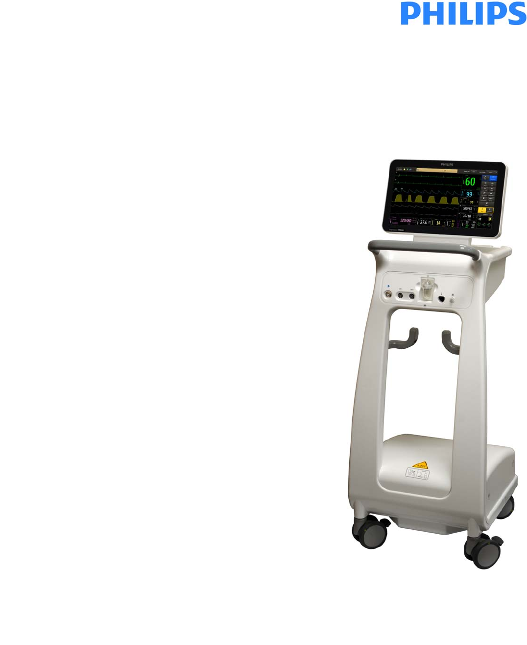
Expression MR400 MRI Patient Monitoring System
INSTRUCTIONS FOR USE
Revision A
English
*989803193211*
989803193211

ii
Manufacturer
Invivo,adivisionofPhilipsMedicalSystems
12151ResearchParkway
Orlando,FL32826,USA
877‐468‐4861
E‐mail:
Info@invivocorp.com
Websites:
www.ExpressionMR.com
www.invivocorp.com
www.philips.com
Identification and Publication Details
PublishedbyInvivo,adivisionofPhilipsMedicalSystems.
Invivo,adivisionofPhilipsMedicalSystems,reservestherighttomakechangestoboththis
InstructionsforUseandtotheproductitdescribes.Productspecificationsaresubjecttochange
withoutnotice.NothingcontainedwithinthisInstructionsforUseisintendedasanyoffer,
warranty,promiseorcontractualcondition,andmustnotbetakenassuch.
©KoninklijkePhilipsN.V.(RoyalPhilips)2015
Allrightsreserved.Reproductioninwholeorinpartinanyformorbyanymeans,electrical,
mechanicalorotherwiseisprohibitedwithoutthewrittenconsentofthecopyrightholder.
REF989803193211Rev.A,March2015
Invivo,adivisionofPhilipsMedicalSystems
12151ResearchParkway
Orlando,FL32826
USA
Unauthorizedcopyingofthispublicationmaynotonlyinfringecopyright,butalsoreducethe
abilityofPhilipsMedicalSystemstoprovideaccurateandup‐to‐dateinformationtousers.
PublishedinUSA
iii
Regulatory
Compliance
TheExpressionMR400MRIPatientMonitoringSystemcomplieswithrelevantinternationaland
nationalstandardsandlaws.Informationoncompliancewillbesuppliedonrequestbyyourlocal
RoyalPhilipsrepresentative,orbythemanufacturer.
Explanation of Symbols
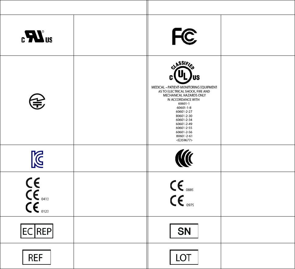
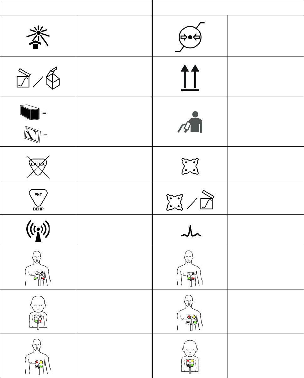
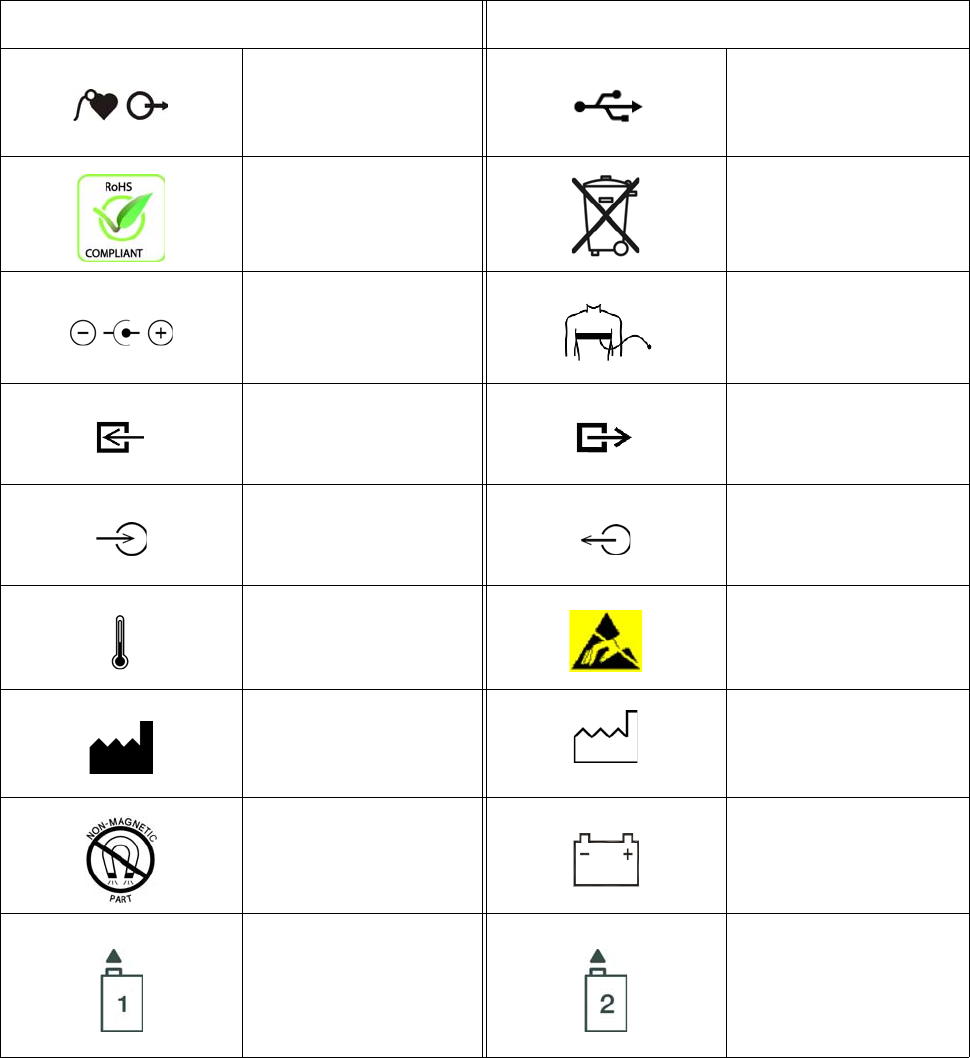
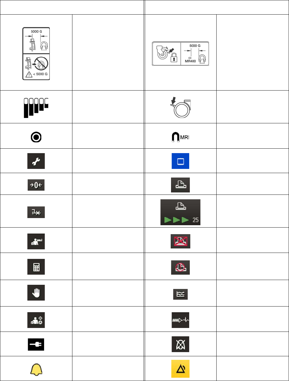
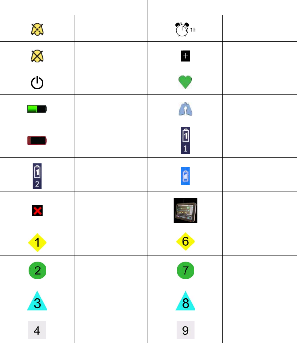
ThesymbolsinthefollowingtablemayappearontheExpressionMR400MRIPatientMonitoring
System,theaccessories,orthepackingmaterial.
Symbol Symbol
Underwriters
Laboratories Component
Recognition Mark for both
the U.S. and Canadian
markets
Federal Communications
Commission radio
certification
Ministry of Internal Affairs
and Communications
Japanese Radio Law
Certification
UL has determined that
the product meets
requirements
Korean Communications
Commission radio
certification
Taiwan National
Communications
Commission certification
Conforms to the
European Medical Devices
Directive
Conforms to the R&TTE
Directive (Radio &
Telecommunications
Terminal Equipment)
Authorized representative
in the European
Community
Serial number
Catalog, reorder or
reference part number Batch code / lot number
iv
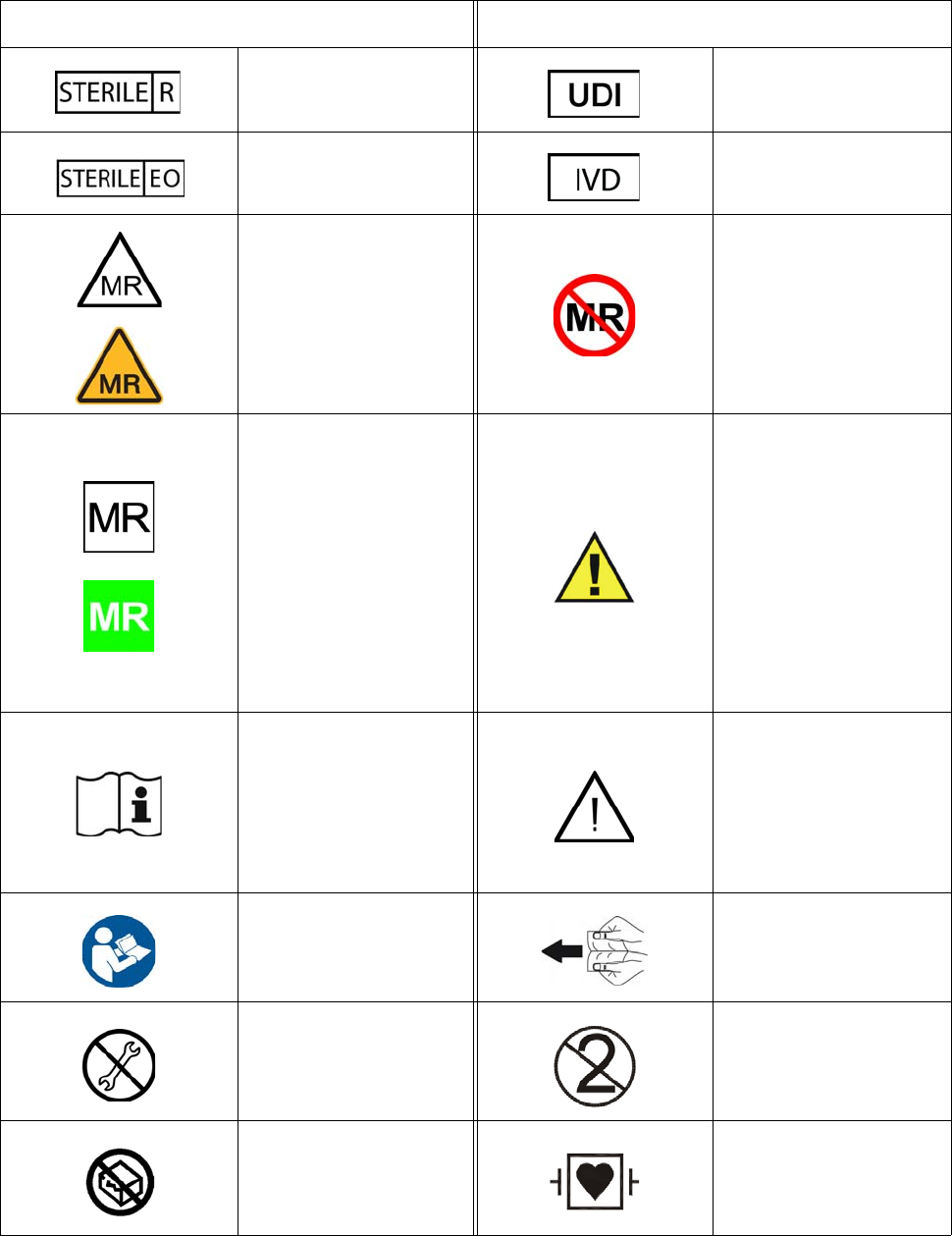
Sterilized using radiation Unique device identifier
Sterilized using ethylene
oxide
In vitro diagnostics
compliant
MR Conditional: Use in
the MR environment is
restricted to certain
conditions of use to
ensure patient and
operator safety.
MR unsafe: Must not be
used in an MRI
environment
MR safe: Completely safe
for use with no potential
for interaction with the
MR field.
Warning! Specific warnings
associated with the
devices that are not
otherwise found on the
label; and, on the
connector of the wireless
ECG patient module, this
indicates that only
specified ECG lead cables
shall be used to ensure
safe use in the MR and
defibrillation protection.
Consult the Instructions for
Use
Caution! See Instructions
for Use for specific
warnings or precautions
associated with the
devices that are not
otherwise found on the
label
The Instructions for Use
must be consulted
Separate to open then
insert
Do not adjust without
referring to the service
manual
Single use only, disposable
one-time-use product; do
not reuse
Do not use if container is
damaged
Defibrillator-proof type
CF equipment (IEC 60601-
1) protection against
shock
Symbol Symbol
v
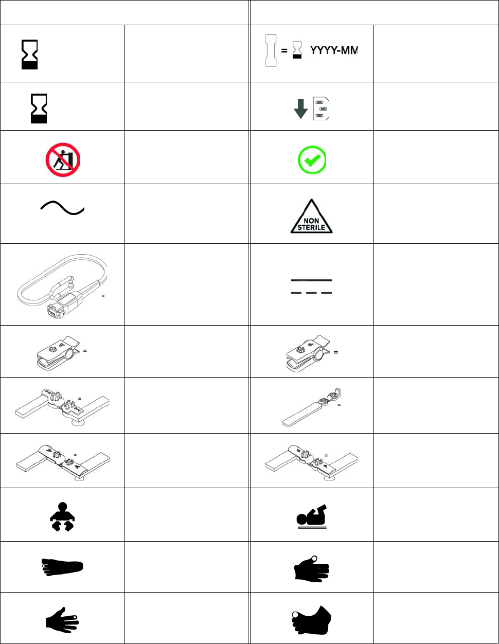
Use by date; do not use
after the year (YYYY),
month (MM) and day
(DD) indicated
Cable tag marked with use
by date; do not use after
the year (YYYY) and
month (MM) indicated
Use by date; do not use
after the year (YYYY),
month (MM)
AC receptacle, below
Do not push Correct
Alternating current Not sterile
SPO2 probe quantity
equals Direct current
Adult SPO2 clip quantity
equals
Pediatric SPO2 clip
quantity equals
Infant SPO2 grip quantity
equals
Neonatal SPO2 grip
quantity equals
Adult SPO2 grip quantity
equals
Pediatric SPO2 grip
quantity equals
Infant Neonate
Toe site Thumb site
Finger site Big toe site
Symbol Symbol
YYYY-MM-DD
YYYY-MM
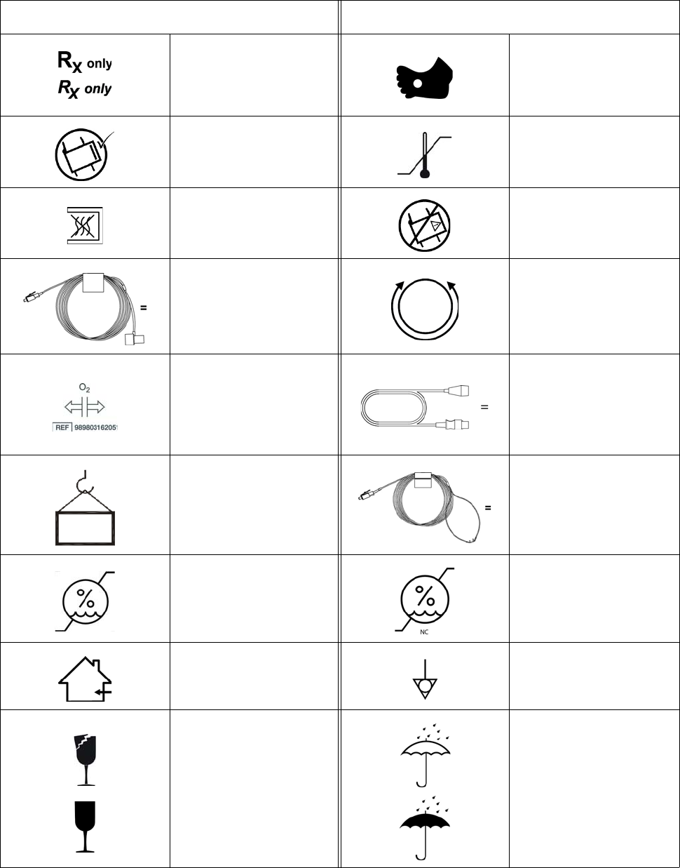
vi
Prescription only Foot site
NIBP cuff, correct side out Temperature range
Non-pyrogenic fluid path NIBP cuff, wrong side out
Airway adapter quantity
equals
NIBP cuff circumference
range
Anesthetic oxygen (O2)
sensor location and part
number
IBP transducer cable
quantity equals
Weight Cannula quantity equals
Humidity range Humidity range, non
condensing
For indoor use only Equipotential (earth)
ground
Fragile Keep dry
Symbol Symbol
vii
Keep away from heat Atmospheric pressure
limitation
Packages per box Up
Quantity equals
Non-invasive blood
pressure (NIBP)
connection
Not manufactured with
natural latex rubber Quadtrode electrode
Contains or presence of
phthalate: bis (2-
ethylhexyl) phthalate
Quadtrode electrode per
package
Non-ionizing radiation ECG
AAMI ECG CV lead cable
connections
AAMI ECG lead cable
connections
AAMI ECG NEO lead
cable connections
IEC ECG CV lead cable
connections
IEC ECG lead cable
connections
IEC ECG NEO lead cable
connections
Symbol Symbol
viii
Cardiac gating output Universal Serial Bus (USB)
Conforms to the RoHS
directive Not for general waste
Center positive
connection: Positive (+)
center pin, negative (-)
outer ring
Pneumatic respiration
connection
Gas input indicator Gas output indicator
Electrical input indicator Electrical output indicator
Temperature connection Electrostatic discharge
(ESD) warning
Manufacturer name and
address YYYY-MM
Date of manufacture
(year-month)
Non-magnetic part Battery
Main battery (left side) Main battery (right side)
Symbol Symbol
ix
Do not move the
Expression MR400 MRI
Patient Monitoring System
inside the 5000 gauss field
line of the MR magnet or
up to the face of a 3T
magnet, whichever is
greater, as measured from
the center line of the
bore.
Apply wheel locks and do
not move the Expression
MR400 MRI Patient
Monitoring System inside
the 5000 gauss field line of
the MR magnet or up to
the face of a 3T magnet,
whichever is greater, as
measured from the center
line of the bore.
Charge indicator, cart
battery Wheel lock
Power level button, cart
battery
MRI compatible, up to
2500 gauss
Setup key Main Screen key
Zero All key Print key, printer ready
indication
Clear Trends key
Print key, printing in
process (and time
remaining) indication
NIBP Interval key Print key, no printer
available indication
1-Touch Alarms key Print key, printer error
indication
Suspend key Trends key
NIBP Start/Stop key ECG Filter key
Connected to AC mains Audio Pause key
Alarm audio armed Alarm key
Symbol Symbol
x
Alarm audio paused
After opening, allow at
least 1 hour to pass before
use
Alarm audio off Current setups have
changed
Power switch (Standby
switch) Heartbeat detected
Module battery adequate
charge indication Breathing effort detected
Module battery low
charge indication
Battery 1 indicator,
wireless ECG patient
module,
Battery 2 indicator,
wireless ECG patient
module,
Battery indicator, wireless
SpO2 patient module
No communication IP5 connected
Network channel 1 Network channel 6
Network channel 2 Network channel 7
Network channel 3 Network channel 8
Network channel 4 Network channel 9
Symbol Symbol
xi
Conventions
CertainconventionsareusedthroughouttheExpressionMR400MRIPatientMonitoringSystem
tospeeduseandfamiliaritywiththedevice.Thisaccompanyinguserinformationalsouses
documentconventionstoassistyouinfindingandunderstandinginformation.
System Conventions
Thefollowingsystemconventionsareused:
•Operationalcontrolisaccomplishedusingthetouchscreen,whereactiveelementsare
providedandtouchingthatelementwillactivate,openorexecutetherelatedmenu,
functionoritem.
•Mostmenusemployatime‐outfeaturewhere,ifnoactionistakenforapproximately30–
60seconds,anopenmenuwillautomaticallyclose.
•Toprotectagainstaccidentalchanges,adialogpromptisassociatedwithsomemenu
options.Whendisplayed,youmustanswerthisprompt;otherwise,adelayof
approximately30–60secondswillbeequivalenttoselectingNo(thiscanalsobe
accomplishedbypressingtheMainScreenkey.)
•Toprotectagainstunauthorizedchanges,somemenuitemsfeaturepasswordprotection.
Youmustenterthecorrectnumericcodeforaccessandadelayofapproximately30–60
secondsisequivalenttomakingnoentry.
Document Conventions
Thesedocumentconventionsareused:
Network channel 5 Network channel 10
Ten FlexTEMP System
Jackets per box
Symbol Symbol

xii
•Allproceduresarenumberedandanysub‐stepsarelettered.Completethestepsinthe
sequencepresentedtoensuresuccess.Proceduresareindicatedbythefollowingtable:
•Unlessnoted,allproceduresstartfromthenormalmodeofoperation.
• SelectmeanstopressonanactiveelementonthetouchscreenLCD(menuorsub‐menu
item,button,key,vitalsignbox,etcetera).
•Bulletedlistsindicategeneralinformationaboutaparticularfeature,menufunctionor
procedure,anddonotimplysequentialorderoroperation.
•Controlnames,menuitems,vitalsignreferences,messages,etcetera,arespelledasthey
appearontheExpressionMR400MRIPatientMonitoringSystem.
•Menuitems,keynamesandmessagesareprovidedinboldfont.
•The“greaterthan”(>)symbolisusedwhennavigationofitemswithinamenuisindicated.
•ThefrontoftheExpressionMR400MRIPatientMonitoringSystemisnearestyouasyou
operateit;theleftandrightsidesarerespectivelytoyourleftandrightasyoustandin
frontofthesystem,facingit.
•Thefrontofawirelessmoduleisnearestyouasyouoperateit.Thetopofthedevice
pointsuporawaywhenthelabelingnearestyouduringoperationiscorrectlyorientedfor
reading,whiletheleftandrightsidesofthedevicearerespectivelytoyourleftandrightas
youholdthedeviceforoperation,facingit.
Step Action
1
2
3
Contents
Contents 1
Manufacturer . . . . . . . . . . . . . . . . . . . . . . . . . . . . . . . . . . . . . . . . . . . . . . . . . . . . . . . . . .1-ii
Identification and Publication Details. . . . . . . . . . . . . . . . . . . . . . . . . . . . . . . . . . . . . . . . 1-ii
Regulatory . . . . . . . . . . . . . . . . . . . . . . . . . . . . . . . . . . . . . . . . . . . . . . . . . . . . . . . . . . . 1-iii
Explanation of Symbols . . . . . . . . . . . . . . . . . . . . . . . . . . . . . . . . . . . . . . . . . . . . . . . . . 1-iii
Conventions . . . . . . . . . . . . . . . . . . . . . . . . . . . . . . . . . . . . . . . . . . . . . . . . . . . . . . . . . . . 1-xi
System Conventions. . . . . . . . . . . . . . . . . . . . . . . . . . . . . . . . . . . . . . . . . . . . . . . . . . . . . . . . 1-xi
Document Conventions . . . . . . . . . . . . . . . . . . . . . . . . . . . . . . . . . . . . . . . . . . . . . . . . . . . . . 1-xi
Chapter 1: Important Information
About . . . . . . . . . . . . . . . . . . . . . . . . . . . . . . . . . . . . . . . . . . . . . . . . . . . . . . . . . . . . . . . . . 1-1
Intended Use . . . . . . . . . . . . . . . . . . . . . . . . . . . . . . . . . . . . . . . . . . . . . . . . . . . . . . . . . . . 1-2
Compatibility. . . . . . . . . . . . . . . . . . . . . . . . . . . . . . . . . . . . . . . . . . . . . . . . . . . . . . . . . . . . 1-2
Indications for Use . . . . . . . . . . . . . . . . . . . . . . . . . . . . . . . . . . . . . . . . . . . . . . . . . . . . . . .1-3
Contra-indications . . . . . . . . . . . . . . . . . . . . . . . . . . . . . . . . . . . . . . . . . . . . . . . . . . . . . . .1-3
Training . . . . . . . . . . . . . . . . . . . . . . . . . . . . . . . . . . . . . . . . . . . . . . . . . . . . . . . . . . . . . . .1-4
Safety. . . . . . . . . . . . . . . . . . . . . . . . . . . . . . . . . . . . . . . . . . . . . . . . . . . . . . . . . . . . . . . . .1-4
Equipment Classification (According to IEC 60601-1) . . . . . . . . . . . . . . . . . . . . . . . . . . . . . . .1-7
Electromagnetic Compatibility (EMC) . . . . . . . . . . . . . . . . . . . . . . . . . . . . . . . . . . . . . . . . 1-8
Radios . . . . . . . . . . . . . . . . . . . . . . . . . . . . . . . . . . . . . . . . . . . . . . . . . . . . . . . . . . . . . . . . . . .1-8
Using Batteries Safely . . . . . . . . . . . . . . . . . . . . . . . . . . . . . . . . . . . . . . . . . . . . . . . . . . . 1-12
Examining the Shipment . . . . . . . . . . . . . . . . . . . . . . . . . . . . . . . . . . . . . . . . . . . . . . . . . 1-13
Disposing of the Packaging . . . . . . . . . . . . . . . . . . . . . . . . . . . . . . . . . . . . . . . . . . . . . . . . . .1-14
Initial Setup . . . . . . . . . . . . . . . . . . . . . . . . . . . . . . . . . . . . . . . . . . . . . . . . . . . . . . . . . . . 1-14
Installing and Connecting Cart Batteries . . . . . . . . . . . . . . . . . . . . . . . . . . . . . . . . . . . . . . . .1-16
Attaching the SpO2 Probe to the wSpO2 Module . . . . . . . . . . . . . . . . . . . . . . . . . . . . . . . . .1-18
Rear Panel Connections . . . . . . . . . . . . . . . . . . . . . . . . . . . . . . . . . . . . . . . . . . . . . . . . . 1-19
Connecting AC Mains Power . . . . . . . . . . . . . . . . . . . . . . . . . . . . . . . . . . . . . . . . . . . . . . . . .1-20
Understanding Battery Operations. . . . . . . . . . . . . . . . . . . . . . . . . . . . . . . . . . . . . . . . . . 1-21
Cart Batteries . . . . . . . . . . . . . . . . . . . . . . . . . . . . . . . . . . . . . . . . . . . . . . . . . . . . . . . . . . . . .1-21
Charging Cart Batteries . . . . . . . . . . . . . . . . . . . . . . . . . . . . . . . . . . . . . . . . . . . . . . . . . . . . .1-21
Removing Cart Batteries . . . . . . . . . . . . . . . . . . . . . . . . . . . . . . . . . . . . . . . . . . . . . . . .1-22
Wireless Module Batteries . . . . . . . . . . . . . . . . . . . . . . . . . . . . . . . . . . . . . . . . . . . . . . . . . . .1-23
Charging Module Batteries . . . . . . . . . . . . . . . . . . . . . . . . . . . . . . . . . . . . . . . . . . . . . .1-24
Installing Batteries in the wECG Module . . . . . . . . . . . . . . . . . . . . . . . . . . . . . . . . . . . .1-24
Removing Batteries from the wECG Module . . . . . . . . . . . . . . . . . . . . . . . . . . . . . . . . .1-25
Installing a Battery in the wSpO2 Module . . . . . . . . . . . . . . . . . . . . . . . . . . . . . . . . . . .1-26
Removing the Battery from the wSpO2 Module . . . . . . . . . . . . . . . . . . . . . . . . . . . . . .1-27
Understanding Wireless Network Operations . . . . . . . . . . . . . . . . . . . . . . . . . . . . . . . . . 1-27
Setting the Wireless Network Channel of the Cart . . . . . . . . . . . . . . . . . . . . . . . . . . . . . . . . .1-27
Setting the Wireless Network Channel of the wECG and wSpO2 Modules . . . . . . . . . . . . . .1-29
Advanced User Options . . . . . . . . . . . . . . . . . . . . . . . . . . . . . . . . . . . . . . . . . . . . . . . . . . 1-33
Expression Information Portal (Model IP5). . . . . . . . . . . . . . . . . . . . . . . . . . . . . . . . . . . . . . .1-33
Additional Options . . . . . . . . . . . . . . . . . . . . . . . . . . . . . . . . . . . . . . . . . . . . . . . . . . . . . . . . .1-33
Accessory List . . . . . . . . . . . . . . . . . . . . . . . . . . . . . . . . . . . . . . . . . . . . . . . . . . . . . . . . .1-33
Chapter 2: System Overview
System Parameters . . . . . . . . . . . . . . . . . . . . . . . . . . . . . . . . . . . . . . . . . . . . . . . . . . . . . .2-1
2 Contents
System Components . . . . . . . . . . . . . . . . . . . . . . . . . . . . . . . . . . . . . . . . . . . . . . . . . . . . . 2-2
Use Model. . . . . . . . . . . . . . . . . . . . . . . . . . . . . . . . . . . . . . . . . . . . . . . . . . . . . . . . . . . . . . . . 2-2
Acquisition and Control . . . . . . . . . . . . . . . . . . . . . . . . . . . . . . . . . . . . . . . . . . . . . . . . . 2-3
Synchronization . . . . . . . . . . . . . . . . . . . . . . . . . . . . . . . . . . . . . . . . . . . . . . . . . . . . . . . 2-3
Device Control . . . . . . . . . . . . . . . . . . . . . . . . . . . . . . . . . . . . . . . . . . . . . . . . . . . . . . . . 2-4
Hardware Features . . . . . . . . . . . . . . . . . . . . . . . . . . . . . . . . . . . . . . . . . . . . . . . . . . . . . . 2-5
Cart . . . . . . . . . . . . . . . . . . . . . . . . . . . . . . . . . . . . . . . . . . . . . . . . . . . . . . . . . . . . . . . . . . . . . 2-5
Display Panel . . . . . . . . . . . . . . . . . . . . . . . . . . . . . . . . . . . . . . . . . . . . . . . . . . . . . . . . . . . . . 2-6
Patient Connection Panel . . . . . . . . . . . . . . . . . . . . . . . . . . . . . . . . . . . . . . . . . . . . . . . . . . . . 2-7
wECG and wSpO2 Modules . . . . . . . . . . . . . . . . . . . . . . . . . . . . . . . . . . . . . . . . . . . . . . . 2-8
wECG Module. . . . . . . . . . . . . . . . . . . . . . . . . . . . . . . . . . . . . . . . . . . . . . . . . . . . . . . . . . . . . 2-9
wECG Module Indicators . . . . . . . . . . . . . . . . . . . . . . . . . . . . . . . . . . . . . . . . . . . . . . . . 2-9
wSpO2 Module . . . . . . . . . . . . . . . . . . . . . . . . . . . . . . . . . . . . . . . . . . . . . . . . . . . . . . . . . . . 2-11
wSpO2 Module Indicators . . . . . . . . . . . . . . . . . . . . . . . . . . . . . . . . . . . . . . . . . . . . . . 2-11
Storing Modules and Accessories . . . . . . . . . . . . . . . . . . . . . . . . . . . . . . . . . . . . . . . . . . 2-12
Displayed Information and Controls. . . . . . . . . . . . . . . . . . . . . . . . . . . . . . . . . . . . . . . . . 2-13
Information Bar . . . . . . . . . . . . . . . . . . . . . . . . . . . . . . . . . . . . . . . . . . . . . . . . . . . . . . . . . . . 2-14
Soft Keypad . . . . . . . . . . . . . . . . . . . . . . . . . . . . . . . . . . . . . . . . . . . . . . . . . . . . . . . . . . . . . 2-15
Status Information Pane . . . . . . . . . . . . . . . . . . . . . . . . . . . . . . . . . . . . . . . . . . . . . . . . . . . . 2-16
Status Information Panel . . . . . . . . . . . . . . . . . . . . . . . . . . . . . . . . . . . . . . . . . . . . . . . 2-18
Vital Sign Boxes . . . . . . . . . . . . . . . . . . . . . . . . . . . . . . . . . . . . . . . . . . . . . . . . . . . . . . . . . . 2-19
No Data Indications . . . . . . . . . . . . . . . . . . . . . . . . . . . . . . . . . . . . . . . . . . . . . . . . . . . 2-20
Other Data Indications . . . . . . . . . . . . . . . . . . . . . . . . . . . . . . . . . . . . . . . . . . . . . . . . . 2-21
Vital Sign Traces and System Message Area. . . . . . . . . . . . . . . . . . . . . . . . . . . . . . . . . . . . 2-21
Navigation and Operation . . . . . . . . . . . . . . . . . . . . . . . . . . . . . . . . . . . . . . . . . . . . . . . . 2-22
Specialized Control Buttons and Keys . . . . . . . . . . . . . . . . . . . . . . . . . . . . . . . . . . . . . . . . . 2-22
Default Setting Indications . . . . . . . . . . . . . . . . . . . . . . . . . . . . . . . . . . . . . . . . . . . . . . . . . . 2-23
System Messages. . . . . . . . . . . . . . . . . . . . . . . . . . . . . . . . . . . . . . . . . . . . . . . . . . . . . . . . . 2-23
Password Protection. . . . . . . . . . . . . . . . . . . . . . . . . . . . . . . . . . . . . . . . . . . . . . . . . . . . . . . 2-23
Modes of Operation . . . . . . . . . . . . . . . . . . . . . . . . . . . . . . . . . . . . . . . . . . . . . . . . . . . . . 2-23
Normal Mode . . . . . . . . . . . . . . . . . . . . . . . . . . . . . . . . . . . . . . . . . . . . . . . . . . . . . . . . . . . . 2-23
Suspend Mode . . . . . . . . . . . . . . . . . . . . . . . . . . . . . . . . . . . . . . . . . . . . . . . . . . . . . . . . . . . 2-24
Simulation Mode . . . . . . . . . . . . . . . . . . . . . . . . . . . . . . . . . . . . . . . . . . . . . . . . . . . . . . . . . . 2-24
Chapter 3: Getting Started
Defibrillator and Electrosurgical Use . . . . . . . . . . . . . . . . . . . . . . . . . . . . . . . . . . . . . . . . . 3-1
Positioning the MR400. . . . . . . . . . . . . . . . . . . . . . . . . . . . . . . . . . . . . . . . . . . . . . . . . . . . 3-2
Operating the MR400. . . . . . . . . . . . . . . . . . . . . . . . . . . . . . . . . . . . . . . . . . . . . . . . . . . . . 3-3
System Power-up and Communications Verification . . . . . . . . . . . . . . . . . . . . . . . . . . . . . . . 3-4
Cart Power-down . . . . . . . . . . . . . . . . . . . . . . . . . . . . . . . . . . . . . . . . . . . . . . . . . . . . . . 3-6
Wireless Module Power-down . . . . . . . . . . . . . . . . . . . . . . . . . . . . . . . . . . . . . . . . . . . . 3-6
Monitor Initialization . . . . . . . . . . . . . . . . . . . . . . . . . . . . . . . . . . . . . . . . . . . . . . . . . . . . . .3-6
Viewing the Displayed Information. . . . . . . . . . . . . . . . . . . . . . . . . . . . . . . . . . . . . . . . . . . 3-7
Default Settings . . . . . . . . . . . . . . . . . . . . . . . . . . . . . . . . . . . . . . . . . . . . . . . . . . . . . . . . . 3-7
Default Setting Indications . . . . . . . . . . . . . . . . . . . . . . . . . . . . . . . . . . . . . . . . . . . . . . . . . . . 3-7
User Settings . . . . . . . . . . . . . . . . . . . . . . . . . . . . . . . . . . . . . . . . . . . . . . . . . . . . . . . . . . . . . 3-8
Initial Alarm Indications . . . . . . . . . . . . . . . . . . . . . . . . . . . . . . . . . . . . . . . . . . . . . . . . . . 3-10
Selecting the Patient Type. . . . . . . . . . . . . . . . . . . . . . . . . . . . . . . . . . . . . . . . . . . . . . . . 3-11
Setup Menus . . . . . . . . . . . . . . . . . . . . . . . . . . . . . . . . . . . . . . . . . . . . . . . . . . . . . . . . . . 3-13
Contents 3
Monitor Setup Menu . . . . . . . . . . . . . . . . . . . . . . . . . . . . . . . . . . . . . . . . . . . . . . . . . . . . . . . .3-14
Edit User Settings . . . . . . . . . . . . . . . . . . . . . . . . . . . . . . . . . . . . . . . . . . . . . . . . . . . . .3-15
Parameters . . . . . . . . . . . . . . . . . . . . . . . . . . . . . . . . . . . . . . . . . . . . . . . . . . . . . . . . . .3-18
Sound Adjust . . . . . . . . . . . . . . . . . . . . . . . . . . . . . . . . . . . . . . . . . . . . . . . . . . . . . . . . .3-20
Set Time & Date . . . . . . . . . . . . . . . . . . . . . . . . . . . . . . . . . . . . . . . . . . . . . . . . . . . . . .3-22
Sweep Speed . . . . . . . . . . . . . . . . . . . . . . . . . . . . . . . . . . . . . . . . . . . . . . . . . . . . . . . .3-25
Resp Speed. . . . . . . . . . . . . . . . . . . . . . . . . . . . . . . . . . . . . . . . . . . . . . . . . . . . . . . . . .3-25
Service(Bio-Med). . . . . . . . . . . . . . . . . . . . . . . . . . . . . . . . . . . . . . . . . . . . . . . . . . . . . .3-26
Revision Information . . . . . . . . . . . . . . . . . . . . . . . . . . . . . . . . . . . . . . . . . . . . . . . . . . .3-28
Simulation Mode . . . . . . . . . . . . . . . . . . . . . . . . . . . . . . . . . . . . . . . . . . . . . . . . . . . . . .3-29
Gas Cal . . . . . . . . . . . . . . . . . . . . . . . . . . . . . . . . . . . . . . . . . . . . . . . . . . . . . . . . . . . . .3-30
System Config . . . . . . . . . . . . . . . . . . . . . . . . . . . . . . . . . . . . . . . . . . . . . . . . . . . . . . . .3-30
ECG Tests . . . . . . . . . . . . . . . . . . . . . . . . . . . . . . . . . . . . . . . . . . . . . . . . . . . . . . . . . . .3-32
NIBP Tests. . . . . . . . . . . . . . . . . . . . . . . . . . . . . . . . . . . . . . . . . . . . . . . . . . . . . . . . . . .3-33
Backlight Brightness . . . . . . . . . . . . . . . . . . . . . . . . . . . . . . . . . . . . . . . . . . . . . . . . . . .3-34
Service Utilities . . . . . . . . . . . . . . . . . . . . . . . . . . . . . . . . . . . . . . . . . . . . . . . . . . . . . . .3-35
Chapter 4: Alarms
Alarm Safety Information . . . . . . . . . . . . . . . . . . . . . . . . . . . . . . . . . . . . . . . . . . . . . . . . . . 4-2
Visual Alarm Indications. . . . . . . . . . . . . . . . . . . . . . . . . . . . . . . . . . . . . . . . . . . . . . . . . . .4-2
Alarm Flags . . . . . . . . . . . . . . . . . . . . . . . . . . . . . . . . . . . . . . . . . . . . . . . . . . . . . . . . . . . . . . .4-2
Flashing Numeric . . . . . . . . . . . . . . . . . . . . . . . . . . . . . . . . . . . . . . . . . . . . . . . . . . . . . . . . . . .4-3
Alarm Light . . . . . . . . . . . . . . . . . . . . . . . . . . . . . . . . . . . . . . . . . . . . . . . . . . . . . . . . . . . . . . . .4-3
Audible Alarm Indications. . . . . . . . . . . . . . . . . . . . . . . . . . . . . . . . . . . . . . . . . . . . . . . . . .4-4
Alarm Sound State Indication. . . . . . . . . . . . . . . . . . . . . . . . . . . . . . . . . . . . . . . . . . . . . . . . . .4-4
Initial Audible Alarm Setting Indications . . . . . . . . . . . . . . . . . . . . . . . . . . . . . . . . . . . . . . . . . .4-5
Controlling the Alarm Audio and Light Indications . . . . . . . . . . . . . . . . . . . . . . . . . . . . . . . . . .4-5
Audio Pause Mode . . . . . . . . . . . . . . . . . . . . . . . . . . . . . . . . . . . . . . . . . . . . . . . . . . . . .4-6
Audio Off Mode . . . . . . . . . . . . . . . . . . . . . . . . . . . . . . . . . . . . . . . . . . . . . . . . . . . . . . . .4-6
Alarm Volume. . . . . . . . . . . . . . . . . . . . . . . . . . . . . . . . . . . . . . . . . . . . . . . . . . . . . . . . . . . . . .4-7
Alarm Reset . . . . . . . . . . . . . . . . . . . . . . . . . . . . . . . . . . . . . . . . . . . . . . . . . . . . . . . . . . . . . . .4-7
Managing Alarm Functions . . . . . . . . . . . . . . . . . . . . . . . . . . . . . . . . . . . . . . . . . . . . . . . . 4-8
Showing or Hiding Current Alarm Limits. . . . . . . . . . . . . . . . . . . . . . . . . . . . . . . . . . . . . . . . . .4-8
Adjusting the Alarm Limits . . . . . . . . . . . . . . . . . . . . . . . . . . . . . . . . . . . . . . . . . . . . . . . . . . . .4-9
Alarm Limit Controls . . . . . . . . . . . . . . . . . . . . . . . . . . . . . . . . . . . . . . . . . . . . . . . . . . . . . . . . .4-9
The Alarm Window . . . . . . . . . . . . . . . . . . . . . . . . . . . . . . . . . . . . . . . . . . . . . . . . . . . .4-11
Advanced Alarm Functions . . . . . . . . . . . . . . . . . . . . . . . . . . . . . . . . . . . . . . . . . . . . . .4-11
Setting Alarm Limits Globally. . . . . . . . . . . . . . . . . . . . . . . . . . . . . . . . . . . . . . . . . . . . .4-12
Setting Alarm Limits Individually . . . . . . . . . . . . . . . . . . . . . . . . . . . . . . . . . . . . . . . . . .4-13
Restoring Alarm Limit Defaults . . . . . . . . . . . . . . . . . . . . . . . . . . . . . . . . . . . . . . . . . . .4-16
Enabling Print on Alarm . . . . . . . . . . . . . . . . . . . . . . . . . . . . . . . . . . . . . . . . . . . . . . . . . . . . .4-17
Alarms Menu . . . . . . . . . . . . . . . . . . . . . . . . . . . . . . . . . . . . . . . . . . . . . . . . . . . . . . . . . .4-17
1-Touch High %. . . . . . . . . . . . . . . . . . . . . . . . . . . . . . . . . . . . . . . . . . . . . . . . . . . . . . .4-18
1-Touch Low % . . . . . . . . . . . . . . . . . . . . . . . . . . . . . . . . . . . . . . . . . . . . . . . . . . . . . . .4-19
Alarm Sound . . . . . . . . . . . . . . . . . . . . . . . . . . . . . . . . . . . . . . . . . . . . . . . . . . . . . . . . .4-20
Alarm Light. . . . . . . . . . . . . . . . . . . . . . . . . . . . . . . . . . . . . . . . . . . . . . . . . . . . . . . . . . .4-20
Default Limits. . . . . . . . . . . . . . . . . . . . . . . . . . . . . . . . . . . . . . . . . . . . . . . . . . . . . . . . .4-21
Limits Display. . . . . . . . . . . . . . . . . . . . . . . . . . . . . . . . . . . . . . . . . . . . . . . . . . . . . . . . .4-21
Adjustable Alarm Limit Ranges . . . . . . . . . . . . . . . . . . . . . . . . . . . . . . . . . . . . . . . . . . . .4-22
4 Contents
Alarm Limit Factory Defaults . . . . . . . . . . . . . . . . . . . . . . . . . . . . . . . . . . . . . . . . . . . . . . 4-24
Measurement Limits and Over / Under Values . . . . . . . . . . . . . . . . . . . . . . . . . . . . . . . . 4-25
Listing of Alarms . . . . . . . . . . . . . . . . . . . . . . . . . . . . . . . . . . . . . . . . . . . . . . . . . . . . . . . 4-26
Patient and INOP Alarms . . . . . . . . . . . . . . . . . . . . . . . . . . . . . . . . . . . . . . . . . . . . . . . . . . . 4-27
Technical (INOP) Alarms and Other Status Flags . . . . . . . . . . . . . . . . . . . . . . . . . . . . . . . . 4-31
ECG . . . . . . . . . . . . . . . . . . . . . . . . . . . . . . . . . . . . . . . . . . . . . . . . . . . . . . . . . . . . . . . 4-31
SPO2 . . . . . . . . . . . . . . . . . . . . . . . . . . . . . . . . . . . . . . . . . . . . . . . . . . . . . . . . . . . . . . 4-32
CO2 / CO (RESP) / AGENT. . . . . . . . . . . . . . . . . . . . . . . . . . . . . . . . . . . . . . . . . . . . . 4-33
P1 (or P2). . . . . . . . . . . . . . . . . . . . . . . . . . . . . . . . . . . . . . . . . . . . . . . . . . . . . . . . . . . 4-35
TEMP . . . . . . . . . . . . . . . . . . . . . . . . . . . . . . . . . . . . . . . . . . . . . . . . . . . . . . . . . . . . . . 4-36
NIBP. . . . . . . . . . . . . . . . . . . . . . . . . . . . . . . . . . . . . . . . . . . . . . . . . . . . . . . . . . . . . . . 4-36
Other Status Indications. . . . . . . . . . . . . . . . . . . . . . . . . . . . . . . . . . . . . . . . . . . . . . . . 4-37
Chapter 5: Monitoring ECG
ECG Monitoring Considerations for the MR Environment . . . . . . . . . . . . . . . . . . . . . . . . . 5-1
wECG Module and ECG Lead Cable. . . . . . . . . . . . . . . . . . . . . . . . . . . . . . . . . . . . . . . . . 5-2
Quadtrode Electrodes . . . . . . . . . . . . . . . . . . . . . . . . . . . . . . . . . . . . . . . . . . . . . . . . . . . . 5-3
Work Flow for ECG Monitoring . . . . . . . . . . . . . . . . . . . . . . . . . . . . . . . . . . . . . . . . . . . . . . . . 5-3
Selecting the ECG Lead Cable and Quadtrode Electrode Type. . . . . . . . . . . . . . . . . . . . . . . 5-5
Identifying the Placement Site for the Quadtrode Electrode. . . . . . . . . . . . . . . . . . . . . . . . . . 5-7
Preparing the Quadtrode Electrode Site. . . . . . . . . . . . . . . . . . . . . . . . . . . . . . . . . . . . . . . . 5-11
Attaching the ECG Lead Cable. . . . . . . . . . . . . . . . . . . . . . . . . . . . . . . . . . . . . . . . . . . . . . . 5-12
Lead Fail Indication . . . . . . . . . . . . . . . . . . . . . . . . . . . . . . . . . . . . . . . . . . . . . . . . . . . 5-15
Checking the ECG Signal Strength. . . . . . . . . . . . . . . . . . . . . . . . . . . . . . . . . . . . . . . . . . . . 5-16
Selecting the Scale . . . . . . . . . . . . . . . . . . . . . . . . . . . . . . . . . . . . . . . . . . . . . . . . . . . 5-16
Changing the Lead View . . . . . . . . . . . . . . . . . . . . . . . . . . . . . . . . . . . . . . . . . . . . . . . 5-17
Minimizing ECG Waveform Noise. . . . . . . . . . . . . . . . . . . . . . . . . . . . . . . . . . . . . . . . . . . . . 5-18
Positioning the ECG Lead Cable and wECG Module for Scanning . . . . . . . . . . . . . . . . . . . 5-19
Selecting the Filter Mode . . . . . . . . . . . . . . . . . . . . . . . . . . . . . . . . . . . . . . . . . . . . . . . 5-22
ECG Waveforms and VS Box . . . . . . . . . . . . . . . . . . . . . . . . . . . . . . . . . . . . . . . . . . . . . 5-22
Changing the Heart Rate Alarm Limits . . . . . . . . . . . . . . . . . . . . . . . . . . . . . . . . . . . . . . . . . 5-24
ECG Menu . . . . . . . . . . . . . . . . . . . . . . . . . . . . . . . . . . . . . . . . . . . . . . . . . . . . . . . . . . . . 5-26
Trace A Lead . . . . . . . . . . . . . . . . . . . . . . . . . . . . . . . . . . . . . . . . . . . . . . . . . . . . . . . . 5-27
Trace B Lead . . . . . . . . . . . . . . . . . . . . . . . . . . . . . . . . . . . . . . . . . . . . . . . . . . . . . . . . 5-28
Scale . . . . . . . . . . . . . . . . . . . . . . . . . . . . . . . . . . . . . . . . . . . . . . . . . . . . . . . . . . . . . . 5-28
Gating Source . . . . . . . . . . . . . . . . . . . . . . . . . . . . . . . . . . . . . . . . . . . . . . . . . . . . . . . 5-29
HR Source . . . . . . . . . . . . . . . . . . . . . . . . . . . . . . . . . . . . . . . . . . . . . . . . . . . . . . . . . . 5-29
HR Tone Source . . . . . . . . . . . . . . . . . . . . . . . . . . . . . . . . . . . . . . . . . . . . . . . . . . . . . 5-30
Filter Mode . . . . . . . . . . . . . . . . . . . . . . . . . . . . . . . . . . . . . . . . . . . . . . . . . . . . . . . . . . 5-31
Extreme HR . . . . . . . . . . . . . . . . . . . . . . . . . . . . . . . . . . . . . . . . . . . . . . . . . . . . . . . . . 5-32
Pediatric ECG . . . . . . . . . . . . . . . . . . . . . . . . . . . . . . . . . . . . . . . . . . . . . . . . . . . . . . . 5-32
T-Wave Suppression . . . . . . . . . . . . . . . . . . . . . . . . . . . . . . . . . . . . . . . . . . . . . . . . . . 5-33
Chapter 6: Monitoring SPO2
wSpO2 Module, SpO2 Probe and SpO2 Attachment . . . . . . . . . . . . . . . . . . . . . . . . . . . . 6-1
Patient Preparation for SpO2 Monitoring. . . . . . . . . . . . . . . . . . . . . . . . . . . . . . . . . . . . . . 6-2
Selecting the Site and SpO2 Attachment . . . . . . . . . . . . . . . . . . . . . . . . . . . . . . . . . . . . . . . . 6-2
Attaching the Clip or Grip to the SpO2 Probe . . . . . . . . . . . . . . . . . . . . . . . . . . . . . . . . 6-3
Contents 5
Applying the SpO2 Attachment to the Patient . . . . . . . . . . . . . . . . . . . . . . . . . . . . . . . . . . . . .6-3
Perfusion Index Value . . . . . . . . . . . . . . . . . . . . . . . . . . . . . . . . . . . . . . . . . . . . . . . . . . . . . . .6-6
Positioning the wSpO2 Module for Scanning . . . . . . . . . . . . . . . . . . . . . . . . . . . . . . . . . . . . . .6-6
SPO2 Waveform and VS Box . . . . . . . . . . . . . . . . . . . . . . . . . . . . . . . . . . . . . . . . . . . . . . 6-8
Assessing Suspicious SPO2 Readings . . . . . . . . . . . . . . . . . . . . . . . . . . . . . . . . . . . . . . . . . .6-9
Changing the SPO2 Waveform Amplitude . . . . . . . . . . . . . . . . . . . . . . . . . . . . . . . . . . . . . . .6-10
Changing the SPO2 Alarm Limits. . . . . . . . . . . . . . . . . . . . . . . . . . . . . . . . . . . . . . . . . . . . . .6-11
SPO2 Menu . . . . . . . . . . . . . . . . . . . . . . . . . . . . . . . . . . . . . . . . . . . . . . . . . . . . . . . . . . .6-12
Size . . . . . . . . . . . . . . . . . . . . . . . . . . . . . . . . . . . . . . . . . . . . . . . . . . . . . . . . . . . . . . . .6-13
Averaging Time . . . . . . . . . . . . . . . . . . . . . . . . . . . . . . . . . . . . . . . . . . . . . . . . . . . . . . .6-14
Perfusion Index . . . . . . . . . . . . . . . . . . . . . . . . . . . . . . . . . . . . . . . . . . . . . . . . . . . . . . .6-15
Gating Source . . . . . . . . . . . . . . . . . . . . . . . . . . . . . . . . . . . . . . . . . . . . . . . . . . . . . . . .6-15
Desat . . . . . . . . . . . . . . . . . . . . . . . . . . . . . . . . . . . . . . . . . . . . . . . . . . . . . . . . . . . . . . .6-15
Desat Time . . . . . . . . . . . . . . . . . . . . . . . . . . . . . . . . . . . . . . . . . . . . . . . . . . . . . . . . . .6-16
HR Source . . . . . . . . . . . . . . . . . . . . . . . . . . . . . . . . . . . . . . . . . . . . . . . . . . . . . . . . . . .6-17
HR Tone Source . . . . . . . . . . . . . . . . . . . . . . . . . . . . . . . . . . . . . . . . . . . . . . . . . . . . . .6-18
Chapter 7: Monitoring CO2 (LoFlo Option)
MR400 Preparation for CO2 Monitoring. . . . . . . . . . . . . . . . . . . . . . . . . . . . . . . . . . . . . . . 7-1
Operation and Use. . . . . . . . . . . . . . . . . . . . . . . . . . . . . . . . . . . . . . . . . . . . . . . . . . . . . . . 7-2
Warm-Up Period. . . . . . . . . . . . . . . . . . . . . . . . . . . . . . . . . . . . . . . . . . . . . . . . . . . . . . . . . . . .7-2
Zero Reference Adjustment . . . . . . . . . . . . . . . . . . . . . . . . . . . . . . . . . . . . . . . . . . . . . . . . . . .7-2
Breath Rate Distortion . . . . . . . . . . . . . . . . . . . . . . . . . . . . . . . . . . . . . . . . . . . . . . . . . . . . . . .7-3
Patient Preparation for CO2 Monitoring. . . . . . . . . . . . . . . . . . . . . . . . . . . . . . . . . . . . . . .7-4
Selecting the CO2 Accessory. . . . . . . . . . . . . . . . . . . . . . . . . . . . . . . . . . . . . . . . . . . . . . . . . .7-4
Connecting the Sampling Line . . . . . . . . . . . . . . . . . . . . . . . . . . . . . . . . . . . . . . . . . . . . . . . . .7-4
Applying the Sampling Line to the Patient . . . . . . . . . . . . . . . . . . . . . . . . . . . . . . . . . . . . . . . .7-6
CO2 Waveform and VS Box . . . . . . . . . . . . . . . . . . . . . . . . . . . . . . . . . . . . . . . . . . . . . . . 7-7
Changing the CO2 and CO2 (RESP) Alarm Limits . . . . . . . . . . . . . . . . . . . . . . . . . . . . . . . . .7-9
Changing the Unit of Measure . . . . . . . . . . . . . . . . . . . . . . . . . . . . . . . . . . . . . . . . . . . . . . . .7-11
CO2 Menu . . . . . . . . . . . . . . . . . . . . . . . . . . . . . . . . . . . . . . . . . . . . . . . . . . . . . . . . . . . .7-12
Size . . . . . . . . . . . . . . . . . . . . . . . . . . . . . . . . . . . . . . . . . . . . . . . . . . . . . . . . . . . . . . . .7-13
Grids . . . . . . . . . . . . . . . . . . . . . . . . . . . . . . . . . . . . . . . . . . . . . . . . . . . . . . . . . . . . . . .7-14
Zero Cal. . . . . . . . . . . . . . . . . . . . . . . . . . . . . . . . . . . . . . . . . . . . . . . . . . . . . . . . . . . . .7-15
Chapter 8: Monitoring Invasive Blood Pressure
Indications and Contraindications . . . . . . . . . . . . . . . . . . . . . . . . . . . . . . . . . . . . . . . . . . . 8-1
Adult and Pediatric Patients . . . . . . . . . . . . . . . . . . . . . . . . . . . . . . . . . . . . . . . . . . . . . . . . . . .8-1
Neonatal Patients . . . . . . . . . . . . . . . . . . . . . . . . . . . . . . . . . . . . . . . . . . . . . . . . . . . . . . . . . . .8-1
Patient Preparation for IBP Monitoring. . . . . . . . . . . . . . . . . . . . . . . . . . . . . . . . . . . . . . . . 8-2
Transducer Component, Connection, and Feature Locations . . . . . . . . . . . . . . . . . . . . . .8-2
MR 400 Preparation for IBP Monitoring . . . . . . . . . . . . . . . . . . . . . . . . . . . . . . . . . . . . . . . 8-3
Adult and Pediatric Patients: Expression MR IBP DPT Kit, A/P (REF 989803194631) . . . . . .8-4
I. Connecting the Reusable Cable to the MR400 . . . . . . . . . . . . . . . . . . . . . . . . . . . . . .8-4
II. Kit Set Up. . . . . . . . . . . . . . . . . . . . . . . . . . . . . . . . . . . . . . . . . . . . . . . . . . . . . . . . . . .8-5
III. Purging Air from the Monitoring Line . . . . . . . . . . . . . . . . . . . . . . . . . . . . . . . . . . . . .8-6
IV. Zeroing, Leveling and Calibration. . . . . . . . . . . . . . . . . . . . . . . . . . . . . . . . . . . . . . . .8-7
V. Connecting the Monitoring Kit to the Patient. . . . . . . . . . . . . . . . . . . . . . . . . . . . . . . .8-8
6 Contents
The IBP transducer must not be mounted to the patient, or patient burn may result. . . 8-8
VI. Fast Flushing . . . . . . . . . . . . . . . . . . . . . . . . . . . . . . . . . . . . . . . . . . . . . . . . . . . . . . 8-9
VII. Checking for Leaks . . . . . . . . . . . . . . . . . . . . . . . . . . . . . . . . . . . . . . . . . . . . . . . . . 8-9
VIII. In the MR Room . . . . . . . . . . . . . . . . . . . . . . . . . . . . . . . . . . . . . . . . . . . . . . . . . . . 8-9
Neonatal Patients: Expression MR IBP DPT Kit, I/N (REF 989803194641). . . . . . . . . . . . . 8-10
I. Connecting the Reusable Cable to the MR400. . . . . . . . . . . . . . . . . . . . . . . . . . . . . 8-10
II. Kit Set Up. . . . . . . . . . . . . . . . . . . . . . . . . . . . . . . . . . . . . . . . . . . . . . . . . . . . . . . . . 8-10
III. Purging Air from the Monitoring Line. . . . . . . . . . . . . . . . . . . . . . . . . . . . . . . . . . . . 8-12
IV. Zeroing, Leveling and Calibration. . . . . . . . . . . . . . . . . . . . . . . . . . . . . . . . . . . . . . 8-12
V. Connecting the Monitoring Kit to the Patient . . . . . . . . . . . . . . . . . . . . . . . . . . . . . . 8-14
VI. Checking for Leaks. . . . . . . . . . . . . . . . . . . . . . . . . . . . . . . . . . . . . . . . . . . . . . . . . 8-15
VII. In the MR Room. . . . . . . . . . . . . . . . . . . . . . . . . . . . . . . . . . . . . . . . . . . . . . . . . . . 8-15
Zeroing the Pressure Transducer . . . . . . . . . . . . . . . . . . . . . . . . . . . . . . . . . . . . . . . . . . 8-16
Systolic/Diastolic Format. . . . . . . . . . . . . . . . . . . . . . . . . . . . . . . . . . . . . . . . . . . . . . . . . . . . 8-17
Mean Format. . . . . . . . . . . . . . . . . . . . . . . . . . . . . . . . . . . . . . . . . . . . . . . . . . . . . . . . . . . . . 8-18
Changing the P1 (or P2) Format. . . . . . . . . . . . . . . . . . . . . . . . . . . . . . . . . . . . . . . . . . . . . . 8-19
Changing the P1 (or P2) Waveform Amplitude. . . . . . . . . . . . . . . . . . . . . . . . . . . . . . . . . . . 8-19
Changing the P1 (or P2) Alarm Limits . . . . . . . . . . . . . . . . . . . . . . . . . . . . . . . . . . . . . . . . . 8-20
Changing the Unit of Measure . . . . . . . . . . . . . . . . . . . . . . . . . . . . . . . . . . . . . . . . . . . . . . . 8-22
P1 (and P2) Menu . . . . . . . . . . . . . . . . . . . . . . . . . . . . . . . . . . . . . . . . . . . . . . . . . . . . . . 8-22
Zero Set . . . . . . . . . . . . . . . . . . . . . . . . . . . . . . . . . . . . . . . . . . . . . . . . . . . . . . . . . . . . 8-24
Set Label . . . . . . . . . . . . . . . . . . . . . . . . . . . . . . . . . . . . . . . . . . . . . . . . . . . . . . . . . . . 8-24
Size . . . . . . . . . . . . . . . . . . . . . . . . . . . . . . . . . . . . . . . . . . . . . . . . . . . . . . . . . . . . . . . 8-25
HR Source . . . . . . . . . . . . . . . . . . . . . . . . . . . . . . . . . . . . . . . . . . . . . . . . . . . . . . . . . . 8-26
Grids. . . . . . . . . . . . . . . . . . . . . . . . . . . . . . . . . . . . . . . . . . . . . . . . . . . . . . . . . . . . . . . 8-26
Grids Size. . . . . . . . . . . . . . . . . . . . . . . . . . . . . . . . . . . . . . . . . . . . . . . . . . . . . . . . . . . 8-27
Format . . . . . . . . . . . . . . . . . . . . . . . . . . . . . . . . . . . . . . . . . . . . . . . . . . . . . . . . . . . . . 8-28
Chapter 9: Monitoring Agents and Gases (AGENT Option)
MR400 Preparation for AGENT Monitoring . . . . . . . . . . . . . . . . . . . . . . . . . . . . . . . . . . . . 9-1
Operation and Use. . . . . . . . . . . . . . . . . . . . . . . . . . . . . . . . . . . . . . . . . . . . . . . . . . . . . . . 9-1
Warm-Up Period . . . . . . . . . . . . . . . . . . . . . . . . . . . . . . . . . . . . . . . . . . . . . . . . . . . . . . . . . . . 9-2
Zero Reference Adjustment . . . . . . . . . . . . . . . . . . . . . . . . . . . . . . . . . . . . . . . . . . . . . . . . . . 9-2
Breath Rate Distortion. . . . . . . . . . . . . . . . . . . . . . . . . . . . . . . . . . . . . . . . . . . . . . . . . . . . . . . 9-3
CO2 Low Flow and Occlusion Conditions . . . . . . . . . . . . . . . . . . . . . . . . . . . . . . . . . . . . . 9-4
Selecting AGENT Accessories . . . . . . . . . . . . . . . . . . . . . . . . . . . . . . . . . . . . . . . . . . . . . 9-5
AGENT Tubing Preparation. . . . . . . . . . . . . . . . . . . . . . . . . . . . . . . . . . . . . . . . . . . . . . . . 9-5
Pre-Use System Checks. . . . . . . . . . . . . . . . . . . . . . . . . . . . . . . . . . . . . . . . . . . . . . . . . . . . . 9-8
Applying the Sampling Line to the Patient . . . . . . . . . . . . . . . . . . . . . . . . . . . . . . . . . . . . . . 9-10
Water Trap Replacement. . . . . . . . . . . . . . . . . . . . . . . . . . . . . . . . . . . . . . . . . . . . . . . . . 9-13
AGENT and GAS VS Boxes . . . . . . . . . . . . . . . . . . . . . . . . . . . . . . . . . . . . . . . . . . . . . . 9-14
Multiple (Mixed) Agents . . . . . . . . . . . . . . . . . . . . . . . . . . . . . . . . . . . . . . . . . . . . . . . . . . . . 9-15
AGENT VS Box. . . . . . . . . . . . . . . . . . . . . . . . . . . . . . . . . . . . . . . . . . . . . . . . . . . . . . . . . . . 9-16
GAS VS Box . . . . . . . . . . . . . . . . . . . . . . . . . . . . . . . . . . . . . . . . . . . . . . . . . . . . . . . . . . . . . 9-17
Changing the AGENT and GAS Alarm Limits. . . . . . . . . . . . . . . . . . . . . . . . . . . . . . . . . . . . 9-17
MAC Window . . . . . . . . . . . . . . . . . . . . . . . . . . . . . . . . . . . . . . . . . . . . . . . . . . . . . . . . . . 9-20
CO2 Waveform and VS Box . . . . . . . . . . . . . . . . . . . . . . . . . . . . . . . . . . . . . . . . . . . . . . 9-22
Changing the CO2 and CO2 (RESP) Alarm Limits. . . . . . . . . . . . . . . . . . . . . . . . . . . . . . . . 9-23
Changing the Unit of Measure . . . . . . . . . . . . . . . . . . . . . . . . . . . . . . . . . . . . . . . . . . . . . . . 9-26
Contents 7
CO2 Menu . . . . . . . . . . . . . . . . . . . . . . . . . . . . . . . . . . . . . . . . . . . . . . . . . . . . . . . . . . . .9-27
Size . . . . . . . . . . . . . . . . . . . . . . . . . . . . . . . . . . . . . . . . . . . . . . . . . . . . . . . . . . . . . . . .9-28
Grids . . . . . . . . . . . . . . . . . . . . . . . . . . . . . . . . . . . . . . . . . . . . . . . . . . . . . . . . . . . . . . .9-29
Zero Cal. . . . . . . . . . . . . . . . . . . . . . . . . . . . . . . . . . . . . . . . . . . . . . . . . . . . . . . . . . . . .9-30
Chapter 10: Monitoring RESP
Patient Preparation for RESP Monitoring. . . . . . . . . . . . . . . . . . . . . . . . . . . . . . . . . . . . . 10-1
Monitoring Respiration using CO2 . . . . . . . . . . . . . . . . . . . . . . . . . . . . . . . . . . . . . . . . . . . . .10-1
Monitoring Respiration using the Bellows. . . . . . . . . . . . . . . . . . . . . . . . . . . . . . . . . . . . . . . .10-1
Bellows Preparation . . . . . . . . . . . . . . . . . . . . . . . . . . . . . . . . . . . . . . . . . . . . . . . . . . . . . 10-2
Respiration VS Box . . . . . . . . . . . . . . . . . . . . . . . . . . . . . . . . . . . . . . . . . . . . . . . . . . . . .10-3
Changing the CO2 (RESP) Alarm Limits . . . . . . . . . . . . . . . . . . . . . . . . . . . . . . . . . . . . . . . .10-5
RESP Menu . . . . . . . . . . . . . . . . . . . . . . . . . . . . . . . . . . . . . . . . . . . . . . . . . . . . . . . . . . . 10-5
Source . . . . . . . . . . . . . . . . . . . . . . . . . . . . . . . . . . . . . . . . . . . . . . . . . . . . . . . . . . . . . .10-7
Apnea . . . . . . . . . . . . . . . . . . . . . . . . . . . . . . . . . . . . . . . . . . . . . . . . . . . . . . . . . . . . . .10-8
Apnea Time . . . . . . . . . . . . . . . . . . . . . . . . . . . . . . . . . . . . . . . . . . . . . . . . . . . . . . . . . .10-8
Chapter 11: Monitoring Temperature
General Usage Precautions. . . . . . . . . . . . . . . . . . . . . . . . . . . . . . . . . . . . . . . . . . . . . . . 11-1
Initial Use . . . . . . . . . . . . . . . . . . . . . . . . . . . . . . . . . . . . . . . . . . . . . . . . . . . . . . . . . . . . . 11-2
Connecting and Disconnecting the Sensor . . . . . . . . . . . . . . . . . . . . . . . . . . . . . . . . . . .11-3
Temperature Measurements . . . . . . . . . . . . . . . . . . . . . . . . . . . . . . . . . . . . . . . . . . . . . . 11-4
Making Surface Temperature Measurements . . . . . . . . . . . . . . . . . . . . . . . . . . . . . . . . . . . .11-4
Making Body Temperature Measurements . . . . . . . . . . . . . . . . . . . . . . . . . . . . . . . . . . . . . .11-5
Placing the Temperature Sensor in a Jacket. . . . . . . . . . . . . . . . . . . . . . . . . . . . . . . . .11-5
Placing the Temperature Sensor at the Body Site. . . . . . . . . . . . . . . . . . . . . . . . . . . . .11-6
Post-Measurement Processing . . . . . . . . . . . . . . . . . . . . . . . . . . . . . . . . . . . . . . . . . . . . 11-7
Accuracy Check . . . . . . . . . . . . . . . . . . . . . . . . . . . . . . . . . . . . . . . . . . . . . . . . . . . . . . . .11-8
TEMP VS Box . . . . . . . . . . . . . . . . . . . . . . . . . . . . . . . . . . . . . . . . . . . . . . . . . . . . . . . . .11-8
Changing the TEMP Alarm Limits . . . . . . . . . . . . . . . . . . . . . . . . . . . . . . . . . . . . . . . . . . . . .11-9
Changing the Unit of Measure . . . . . . . . . . . . . . . . . . . . . . . . . . . . . . . . . . . . . . . . . . . . . . .11-10
TEMP Menu . . . . . . . . . . . . . . . . . . . . . . . . . . . . . . . . . . . . . . . . . . . . . . . . . . . . . . . . . . 11-10
Units. . . . . . . . . . . . . . . . . . . . . . . . . . . . . . . . . . . . . . . . . . . . . . . . . . . . . . . . . . . . . . .11-11
Chapter 12: Monitoring NIBP
Patient Preparation for NIBP Monitoring . . . . . . . . . . . . . . . . . . . . . . . . . . . . . . . . . . . . .12-2
Selecting the NIBP Cuff . . . . . . . . . . . . . . . . . . . . . . . . . . . . . . . . . . . . . . . . . . . . . . . . . . . . .12-3
Positioning the NIBP Cuff. . . . . . . . . . . . . . . . . . . . . . . . . . . . . . . . . . . . . . . . . . . . . . . . . . . .12-5
Connecting the NIBP Cuff . . . . . . . . . . . . . . . . . . . . . . . . . . . . . . . . . . . . . . . . . . . . . . . .12-5
Choosing the Measurement Mode . . . . . . . . . . . . . . . . . . . . . . . . . . . . . . . . . . . . . . . . . . . . .12-6
Making Automatic Measurements . . . . . . . . . . . . . . . . . . . . . . . . . . . . . . . . . . . . . . . . .12-6
Making Manual Measurements . . . . . . . . . . . . . . . . . . . . . . . . . . . . . . . . . . . . . . . . . . .12-7
Initial Inflation Pressures and Reading Durations. . . . . . . . . . . . . . . . . . . . . . . . . . . . . . . . . .12-7
Stopping an NIBP Measurement . . . . . . . . . . . . . . . . . . . . . . . . . . . . . . . . . . . . . . . . . . . . . .12-8
Suspend Mode during NIBP Measurements . . . . . . . . . . . . . . . . . . . . . . . . . . . . . . . . . . . . .12-8
NIBP VS Box . . . . . . . . . . . . . . . . . . . . . . . . . . . . . . . . . . . . . . . . . . . . . . . . . . . . . . . . . .12-8
Systolic/Diastolic Format . . . . . . . . . . . . . . . . . . . . . . . . . . . . . . . . . . . . . . . . . . . . . . . . . . . .12-8
8 Contents
Mean Format. . . . . . . . . . . . . . . . . . . . . . . . . . . . . . . . . . . . . . . . . . . . . . . . . . . . . . . . . . . . 12-10
Changing the NIBP Format. . . . . . . . . . . . . . . . . . . . . . . . . . . . . . . . . . . . . . . . . . . . . . . . . 12-11
Changing the Unit of Measure . . . . . . . . . . . . . . . . . . . . . . . . . . . . . . . . . . . . . . . . . . . . . . 12-11
Changing the NIBP Alarm Limits . . . . . . . . . . . . . . . . . . . . . . . . . . . . . . . . . . . . . . . . . . . . 12-12
NIBP Menu. . . . . . . . . . . . . . . . . . . . . . . . . . . . . . . . . . . . . . . . . . . . . . . . . . . . . . . . . . . 12-14
Interval . . . . . . . . . . . . . . . . . . . . . . . . . . . . . . . . . . . . . . . . . . . . . . . . . . . . . . . . . . . . 12-15
Auto Mode . . . . . . . . . . . . . . . . . . . . . . . . . . . . . . . . . . . . . . . . . . . . . . . . . . . . . . . . . 12-16
Format . . . . . . . . . . . . . . . . . . . . . . . . . . . . . . . . . . . . . . . . . . . . . . . . . . . . . . . . . . . . 12-17
Chapter 1:3 Trend Data and Printing
Trending Functions . . . . . . . . . . . . . . . . . . . . . . . . . . . . . . . . . . . . . . . . . . . . . . . . . . . . . 13-1
Viewing Tabular Trend Data . . . . . . . . . . . . . . . . . . . . . . . . . . . . . . . . . . . . . . . . . . . . . . . . . 13-1
Tabular Trends Menu . . . . . . . . . . . . . . . . . . . . . . . . . . . . . . . . . . . . . . . . . . . . . . . . . . . . . . 13-1
Trend Arrows . . . . . . . . . . . . . . . . . . . . . . . . . . . . . . . . . . . . . . . . . . . . . . . . . . . . . . . . 13-4
Arrow Period . . . . . . . . . . . . . . . . . . . . . . . . . . . . . . . . . . . . . . . . . . . . . . . . . . . . . . . . 13-6
Data Interval. . . . . . . . . . . . . . . . . . . . . . . . . . . . . . . . . . . . . . . . . . . . . . . . . . . . . . . . . 13-7
Clear Trends . . . . . . . . . . . . . . . . . . . . . . . . . . . . . . . . . . . . . . . . . . . . . . . . . . . . . . . . 13-8
Print Page . . . . . . . . . . . . . . . . . . . . . . . . . . . . . . . . . . . . . . . . . . . . . . . . . . . . . . . . . . 13-9
Print All. . . . . . . . . . . . . . . . . . . . . . . . . . . . . . . . . . . . . . . . . . . . . . . . . . . . . . . . . . . . . 13-9
Stop Print . . . . . . . . . . . . . . . . . . . . . . . . . . . . . . . . . . . . . . . . . . . . . . . . . . . . . . . . . . . 13-9
Printing Functions . . . . . . . . . . . . . . . . . . . . . . . . . . . . . . . . . . . . . . . . . . . . . . . . . . . . . 13-10
Printing Parameter-Specific Trends . . . . . . . . . . . . . . . . . . . . . . . . . . . . . . . . . . . . . . . . . . 13-10
Controlling Printer Outputs . . . . . . . . . . . . . . . . . . . . . . . . . . . . . . . . . . . . . . . . . . . . . . . . . 13-10
Printer Indications . . . . . . . . . . . . . . . . . . . . . . . . . . . . . . . . . . . . . . . . . . . . . . . . . . . . . . . . 13-11
Printer Menu . . . . . . . . . . . . . . . . . . . . . . . . . . . . . . . . . . . . . . . . . . . . . . . . . . . . . . . . . 13-11
Trace 1. . . . . . . . . . . . . . . . . . . . . . . . . . . . . . . . . . . . . . . . . . . . . . . . . . . . . . . . . . . . 13-13
Trace 2. . . . . . . . . . . . . . . . . . . . . . . . . . . . . . . . . . . . . . . . . . . . . . . . . . . . . . . . . . . . 13-14
Trace Delay . . . . . . . . . . . . . . . . . . . . . . . . . . . . . . . . . . . . . . . . . . . . . . . . . . . . . . . . 13-15
Chapter 14: Maintenance and Troubleshooting
General Cleaning Guidelines. . . . . . . . . . . . . . . . . . . . . . . . . . . . . . . . . . . . . . . . . . . . . . 14-1
Removing all Power to the MR400 . . . . . . . . . . . . . . . . . . . . . . . . . . . . . . . . . . . . . . . . . 14-2
Restoring all Power to the MR400 . . . . . . . . . . . . . . . . . . . . . . . . . . . . . . . . . . . . . . . . . . . . 14-4
Removing Power from the Wireless Modules . . . . . . . . . . . . . . . . . . . . . . . . . . . . . . . . . 14-4
Restoring Power to the Wireless Modules . . . . . . . . . . . . . . . . . . . . . . . . . . . . . . . . . . . . . . 14-4
User Routine-Checks and Planned Maintenance . . . . . . . . . . . . . . . . . . . . . . . . . . . . . . 14-4
Cleaning, Disinfection, and Damage Inspection . . . . . . . . . . . . . . . . . . . . . . . . . . . . . . . 14-6
Cleaning, Disinfecting, and Inspecting the Accessories. . . . . . . . . . . . . . . . . . . . . . . . 14-7
Cleaning, Disinfecting, and Inspecting MR400 and Wireless Modules . . . . . . . . . . . . 14-9
Sterilization . . . . . . . . . . . . . . . . . . . . . . . . . . . . . . . . . . . . . . . . . . . . . . . . . . . . . . . . . . 14-10
Testing Alarms. . . . . . . . . . . . . . . . . . . . . . . . . . . . . . . . . . . . . . . . . . . . . . . . . . . . . . . . 14-11
Testing a Dropped Wireless Module . . . . . . . . . . . . . . . . . . . . . . . . . . . . . . . . . . . . . . . 14-12
Verification Testing . . . . . . . . . . . . . . . . . . . . . . . . . . . . . . . . . . . . . . . . . . . . . . . . . . . . 14-13
Anesthetic Oxygen (O2) Sensor Depletion . . . . . . . . . . . . . . . . . . . . . . . . . . . . . . . . . . 14-13
Replacing the O2 Sensor . . . . . . . . . . . . . . . . . . . . . . . . . . . . . . . . . . . . . . . . . . . . . . . . . . 14-13
Updating Software . . . . . . . . . . . . . . . . . . . . . . . . . . . . . . . . . . . . . . . . . . . . . . . . . . . . . 14-15
Calibrating the Touch Screen . . . . . . . . . . . . . . . . . . . . . . . . . . . . . . . . . . . . . . . . . . . . 14-16
Troubleshooting . . . . . . . . . . . . . . . . . . . . . . . . . . . . . . . . . . . . . . . . . . . . . . . . . . . . . . . 14-16
Contents 9
Repair . . . . . . . . . . . . . . . . . . . . . . . . . . . . . . . . . . . . . . . . . . . . . . . . . . . . . . . . . . . . . . 14-16
Environmental Requirements . . . . . . . . . . . . . . . . . . . . . . . . . . . . . . . . . . . . . . . . . . . . 14-17
Passing the Product on to another User . . . . . . . . . . . . . . . . . . . . . . . . . . . . . . . . . . . . 14-18
Packaging the MR400. . . . . . . . . . . . . . . . . . . . . . . . . . . . . . . . . . . . . . . . . . . . . . . . . . . . . 14-18
Final Disposal of the Product . . . . . . . . . . . . . . . . . . . . . . . . . . . . . . . . . . . . . . . . . . . . 14-21
Disposal of the MR400 and Accessories. . . . . . . . . . . . . . . . . . . . . . . . . . . . . . . . . . . . . . . 14-21
Fitting, Removing and Disposing of Batteries . . . . . . . . . . . . . . . . . . . . . . . . . . . . . . . . . . . 14-22
Appendix A: Specifications
General . . . . . . . . . . . . . . . . . . . . . . . . . . . . . . . . . . . . . . . . . . . . . . . . . . . . . . . . . . . . . . . A-1
Displayed Information . . . . . . . . . . . . . . . . . . . . . . . . . . . . . . . . . . . . . . . . . . . . . . . . . . . . A-6
ECG. . . . . . . . . . . . . . . . . . . . . . . . . . . . . . . . . . . . . . . . . . . . . . . . . . . . . . . . . . . . . . . . . . A-7
Pulse Oximeter . . . . . . . . . . . . . . . . . . . . . . . . . . . . . . . . . . . . . . . . . . . . . . . . . . . . . . . . .A-9
CO2 (Optional LoFlo) . . . . . . . . . . . . . . . . . . . . . . . . . . . . . . . . . . . . . . . . . . . . . . . . . . . A-10
Invasive Blood Pressure (Optional). . . . . . . . . . . . . . . . . . . . . . . . . . . . . . . . . . . . . . . . . A-13
AGENT (Optional) . . . . . . . . . . . . . . . . . . . . . . . . . . . . . . . . . . . . . . . . . . . . . . . . . . . . . . A-15
Bellows Respiration. . . . . . . . . . . . . . . . . . . . . . . . . . . . . . . . . . . . . . . . . . . . . . . . . . . . . A-23
Temperature (Optional). . . . . . . . . . . . . . . . . . . . . . . . . . . . . . . . . . . . . . . . . . . . . . . . . . A-23
Non-Invasive Blood Pressure . . . . . . . . . . . . . . . . . . . . . . . . . . . . . . . . . . . . . . . . . . . . . A-24
Gating Outputs . . . . . . . . . . . . . . . . . . . . . . . . . . . . . . . . . . . . . . . . . . . . . . . . . . . . . . . . A-28
Appendix B: Warranty
Warranty Statement . . . . . . . . . . . . . . . . . . . . . . . . . . . . . . . . . . . . . . . . . . . . . . . . . . . . . B-1
Appendix C: Regulatory Information
European Union . . . . . . . . . . . . . . . . . . . . . . . . . . . . . . . . . . . . . . . . . . . . . . . . . . . . . . . . C-1
Declaration of Conformity . . . . . . . . . . . . . . . . . . . . . . . . . . . . . . . . . . . . . . . . . . . . . . . . . . . .C-1
Authorized Representative . . . . . . . . . . . . . . . . . . . . . . . . . . . . . . . . . . . . . . . . . . . . . . . . . . . C-1
Australia . . . . . . . . . . . . . . . . . . . . . . . . . . . . . . . . . . . . . . . . . . . . . . . . . . . . . . . . . . . . . . C-1
Appendix D: Gating Feature
MR400 Preparation for Gating . . . . . . . . . . . . . . . . . . . . . . . . . . . . . . . . . . . . . . . . . . . . . D-1
Gating Connector Pin-outs . . . . . . . . . . . . . . . . . . . . . . . . . . . . . . . . . . . . . . . . . . . . . . . . . . . D-1
Using the Gating Feature . . . . . . . . . . . . . . . . . . . . . . . . . . . . . . . . . . . . . . . . . . . . . . . . . D-2
Using ECG Gating. . . . . . . . . . . . . . . . . . . . . . . . . . . . . . . . . . . . . . . . . . . . . . . . . . . . . . . . . . D-2
Using SPO2 Gating. . . . . . . . . . . . . . . . . . . . . . . . . . . . . . . . . . . . . . . . . . . . . . . . . . . . . . . . . D-4
Appendix E: Guidelines and References
Guidelines for the Prevention of Excessive Heating and Burns Associated with Magnetic
Resonance Procedures. . . . . . . . . . . . . . . . . . . . . . . . . . . . . . . . . . . . . . . . . . . . . . . . . . . . . . .E-1
References . . . . . . . . . . . . . . . . . . . . . . . . . . . . . . . . . . . . . . . . . . . . . . . . . . . . . . . . . . . . E-3
10 Contents
ExpressionMR400InstructionsforUseImportantInformation1‐1
CHAPTER 1
Important Information
About
AbouttheExpressionMR400MRIPatientMonitoringSystemandthisInstructionsforUse
ThisInstructionsforUseisintendedtoassistusersinthesafeandeffectiveoperationofthe
ExpressionMR400MRIPatientMonitoringSystem.
Beforeattemptingtooperatetheproduct,youmustreadthisInstructionsforUse,notingand
strictlyobservingallWARNINGSandCAUTIONnotices.
PayspecialattentiontoalltheinformationgivenandproceduresdescribedintheSAFETY
section.
AWARNINGalertsyoutoapotentialseriousoutcome,adverseeventorsafetyhazard.Failureto
observeawarningmayresultindeathorseriousinjurytotheuserorpatient.
ACAUTIONalertsyoutowherespecialcareisnecessaryforthesafeandeffectiveuseofthe
product.Failuretoobserveacautionmayresultinminorormoderatepersonalinjuryordamage
totheproductorotherproperty,andpossiblyinaremoteriskofmoreseriousinjury,and/or
causeenvironmentalpollution.
ANotehighlightsanunusualpointasanaidtoauser.
ThisInstructionsforUsedescribesthemostextensiveconfigurationoftheproduct,withthe
maximumnumberofoptionsandaccessories.Noteveryfunctiondescribedmaybeavailableon
yourproduct.
Thisproductwillperforminconformitywiththedescriptioncontainedinthismanualand
accompanyinglabelingwhenoperated,maintainedandrepairedinaccordancewiththe
instructionsprovided.
Thisdevicemustbecheckedandcalibratedperiodically.Amalfunctioningdevicemustnotbe
used.Partsthatarebroken,missing,plainlyworn,distorted,orcontaminatedmustbereplaced
immediately.Referthedevicetoqualifiedservicepersonnelforrepairorreplacement.This
deviceoranyofitspartsmustnotberepairedotherthaninaccordancewithwritteninstructions
providedbythemanufacturer.ThedeviceshallnotbealteredwithoutwrittenapprovalofRoyal
Philips.Theuserhasthesoleresponsibilityforanymalfunctionwhichresultsfromimproperuse,
faultymaintenance,improperrepair,damageoralterationbyanyoneotherthanauthorized
servicepersonnel.
1‐2ImportantInformationExpressionMR400InstructionsforUse
Intended Use
ThisPhilipsproductisintendedtobeusedandoperatedonlyinaccordancewiththesafety
proceduresandoperatinginstructionsgiveninthisInstructionsforUseforthepurposesfor
whichitwasdesigned.Thepurposesforwhichtheproductisintendedisgivenbelow.However,
nothingstatedinthisInstructionsforUsereducesusers’responsibilitiesforsoundclinical
judgmentandbestclinicalprocedure.
TheExpressionMR400MRIPatientMonitoringSystemisintendedforusebyhealthcare
professionalstomonitorvitalsignsofpatientsundergoingMRIproceduresandtoprovidesignals
forthesynchronizationoftheMRIscanner.
Useandoperationofthisproductissubjecttothelawinthejurisdiction(s)inwhichtheproduct
isbeingused.Usersmustonlyinstall,useandoperatetheproductinsuchwaysasdonotconflict
withapplicablelaws,orregulations,whichhavetheforceoflaw.Usesoftheproductfor
purposesotherthanthoseintendedandexpresslystatedbythemanufacturer,aswellas
incorrectuseoroperation,mayrelievethemanufacturer(orhisagent)fromallorsome
responsibilityforresultantnon‐compliance,damageorinjury.
CAUTION
Federal law restricts this device to sale by or on the order of a physician.
Compatibility
Theproductdescribedinthismanualshouldnotbeusedincombinationwithotherproductsor
componentsunlesssuchotherproductsorcomponentsareexpresslyrecognizedascompatible
byPhilipsMedicalSystems.[Alistofsuchproductsandcomponentsisavailablefromthe
manufacturer].Changesand/oradditionstotheproductshouldonlybecarriedoutbyPhilips
MedicalSystemsorbythirdpartiesexpresslyauthorizedbyPhilipsMedicalSystemstodoso.
Suchchangesand/oradditionsmustcomplywithallapplicablelawsandregulationsthathave
theforceoflawwithinthejurisdiction(s)concerned,andwithbestengineeringpractice.
Warning
WARNING
Changes and/or additions to the product that are carried out by persons without the
appropriate training and/or using unapproved spare parts may lead to the PMS warranty
being voided. As with all complex technical products, maintenance by persons not
appropriately qualified and/or using unapproved spare parts carries serious risks of damage
to the product and of personal injury.
ExpressionMR400InstructionsforUseImportantInformation1‐3
Indications for Use
TheExpressionMR400MRIPatientMonitoringSystemisintendedforusebyhealthcare
professionalstomonitorvitalsignsofpatientsundergoingMRIproceduresandtoprovidesignals
forsynchronizationfortheMRIscanner(alsoreferredtoas“triggering”or“gating”). The
ExpressionMR400providesmonitoringforthefollowingvitalsignsandparameters:
electrocardiogram(ECG),pulseoximetry(SpO2),non‐invasivebloodpressure(NIBP);and
optionally,invasivebloodpressure(IBP),carbondioxide(CO2)andrespirationrate,anesthetic
agents,oxygen(O2),nitrousoxide(N2O),andtemperature.
Notes
• The MR400 is intended to be used to monitor the vital signs of a patient in an MR magnet
room. Monitoring outside the magnet room (e.g., the MR induction and/or MR recovery
areas) is acceptable for the short duration of time in which the patient is being prepared for
the MR scan and during the recovery period within the MR. This system is not intended for
use on a patient being transported outside of a health care facility.
• The MR400 is intended for use on patients receiving MR scans, which may include
neonatal, pediatric, or adult patients. If determined by a qualified healthcare provider, this
may also include pregnant patients.
• The bellows-derived respiration rate measurement is not intended for vital sign monitoring.
Contra-indications
ThisPhilipsproductshouldnotbeusedifanyofthefollowingcontra‐indicationsexistorare
thoughttoexist.Thisdeviceiscontra‐indicatedforpatientswithmetallicwires,implants,stents,
etcetera.Screenallpatientsformetallicwires,implants,stents,etceterapriortoMR
procedures.TheseelectricalconductorswillreactwiththeMRenvironmentorwiththe
accessory(ifapplieddirectlyovertheconductor),thusincreasingtheriskofheating.The
warningsbelowrefertotheExpressionMR400MRIPatientMonitoringSysteminitsentirety.
WARNINGS
•The Expression MR400 MRI Patient Monitoring System is not intended for use with
patients using pacemakers or electrical stimulators.
•Do not use if MR workers are present who have metallic wires, implants, stents, et
cetera. Screen all MR workers for metallic wires, implants, stents, et cetera, prior to
MR procedures when using the Expression MR400 MRI Patient Monitoring System in
the MR magnet room.
• Do not use on patients with metallic wires, implants, stents, et cetera. Screen all
patients for metallic wires, implants, stents, et cetera, prior to MR procedures. These
electrical conductors will react with the MR environment or with the accessory (if
applied directly over the conductor), thus increasing the risk of heating.

1‐4ImportantInformationExpressionMR400InstructionsforUse
Training
Usersofthisproductmusthavereceivedadequatetrainingonitssafeandeffectiveusebefore
attemptingtooperatetheproductdescribedinthisInstructionsforUse.Trainingrequirements
forthistypeofdevicewillvaryfromcountrytocountry.Usersmustmakesuretheyreceive
adequatetraininginaccordancewithlocallawsorregulations.Ifyourequirefurtherinformation
abouttrainingintheuseofthisproduct,pleasecontactyourlocalPhilipsMedicalSystems
representative.Alternatively,contactthemanufacturer.
ADEQUATETRAINING
WARNINGS
•Do not use the product for any application until you have received adequate and
proper training in its safe and effective operation. If you are unsure of your ability to
operate this product safely and effectively DO NOT USE IT. Operation of this product
without proper and adequate training could lead to fatal or other serious personal
injury. It could also lead to clinical mis-diagnosis or to clinical mistreatment.
• Do not operate the product with patients unless you have an adequate understanding
of its capabilities and functions. Using this product without such an understanding
may compromise its effectiveness and/or reduce the safety of the patient, you and
others.
Safety
BeforeusingtheExpressionMR400MRIPatientMonitoringSystem,readthesafetyinformation
below.ThewarningsbelowrefertotheExpressionMR400MRIPatientMonitoringSysteminits
entirety.
MAINTENANCE&FAULTS
Warning
WARNING
Do not use the product for any application until you are sure that the user routine-checks
have been satisfactorily completed, and that the periodic maintenance of the product is up to
date. If any part of the product is known (or suspected) to be defective or wrongly adjusted,
DO NOT USE the product until a repair has been made. Operation of the product with
defective or wrongly adjusted components could expose the user or the patient to safety
hazards. This could lead to fatal or other serious personal injury, or to clinical misdiagnosis,
or to clinical mistreatment.
ExpressionMR400InstructionsforUseImportantInformation1‐5
SAFETYAWARENESS
Warning
WARNING
Do not use the product for any application until you have read, understood and know all the
safety information, safety procedures and emergency procedures contained in this SAFETY
section. Operation of the product without a proper awareness of how to use it safely could
lead to fatal or other serious personal injury. It could also lead to clinical misdiagnosis or to
clinical mistreatment.
SAFETYDEVICES
Warning
WARNING
Never attempt to remove, modify, or over-ride or frustrate any safety device on the product.
Interfering with safety devices could lead to fatal or other serious personal injury.
INTENDEDUSEANDCOMPATIBILITY
Warning
WARNING
Do not use the product for any purpose other than those for which it is intended. Do not use
the product with any product other than that which Philips Medical Systems recognizes as
compatible. Operation of the product for unintended purposes, or with incompatible
product, could lead to fatal or other serious injury. It could also lead to clinical misdiagnosis
or to clinical mistreatment.
ELECTRICALSAFETY
Warning
WARNING
Do not remove covers or cables from this product (unless expressly instructed to do so in this
Instructions for Use). Dangerous electrical voltages are present within this product.
Removing covers or cables could lead to serious or fatal personal injury.
Covers or cables should [normally] only be removed by qualified and authorized service
personnel. Use this product in rooms or areas that comply with all applicable law (or regulations
having the force of law) concerning electrical safety for this type of product.
Electrically isolate this product from the mains electrical supply before cleaning or disinfecting.
Equipotential ground connection: An equipotential ground (earth) connection point is provided.
Use this product in areas meeting local standards for electrical safety in rooms used for medical
purposes, for example the US National Electrical Code. IEC 60601 also gives guidance about an
equipotential ground (earth) connection point.
Additional equipotential ground connection: An additional equipotential ground (earth) connection
point is provided, because the product is transportable and the reliability of the main equipotential
ground connection point might be insufficient.
1‐6ImportantInformationExpressionMR400InstructionsforUse
MECHANICALSAFETY
Warning
WARNING
Do not remove covers from this product unless expressly instructed to do so in this
Instructions for Use. Moving parts are present within this product. Removing covers could
lead to serious or fatal personal injury.
Covers should normally only be removed by qualified and authorized service personnel. In this
context, qualified means those legally permitted to work on this type of medical electrical product
in the jurisdiction(s) in which the product is being used, and authorized means those authorized by
the user of the product.
FIRESAFETY
Useofanelectricalproductinanenvironmentforwhichitwasnotdesignedcanleadtofireor
explosion.Fireregulationsforthetypeofmedicalareabeingusedshouldbefullyapplied,
observedandenforced.Fireextinguishersshouldbeavailableforbothelectricalandnon‐
electricalfires.
Warning
WARNING
Only use extinguishers on electrical or chemical fires, which are specifically labeled for those
purposes. Using water or other liquids on an electrical fire can lead to fatal or other serious
personal injury.
Ifitissafetodoso,attempttoisolatetheproductfromelectricalandothersuppliesbefore
attemptingtofightafire.Thiswillreducetheriskofelectricshocks.
ELECTROSTATICDISCHARGE
Electrostaticdischarge(ESD)canamounttoasignificantvoltage,whichmaycausedamageto
PCBsorothersystemcomponents.
Caution
CAUTIONS
• Always wait at least ten seconds after the product is switched OFF before switching the
product back to ON.
• Always use proper static procedures, protection, and product prior to opening and during
handling of this product. This product contains components that are electrostatic sensitive.
Failure to use ESD procedures may cause damage to these components. Such damage to
components is not covered by Philips warranties.
ConnectionstosensitivepartsareidentifiedbytheESDwarningsymbol(see
inset).ESDdamageiscumulativeandmaynotbeapparentatfirst,asindicated
byahardfailure,butcancausedegradedperformance.Therefore,alwaysuse
properESDhandlingprocedures.ESDcanresultfromlowhumidityconditions,
useofelectricalequipmentoncarpeting,linens,andclothing.

ExpressionMR400InstructionsforUseImportantInformation1‐7
ELECTROMAGNETICCOMPATIBILITY(EMC)
ThisPhilipsproductcomplieswithrelevantinternationalandnationallawandstandardsonEMC
(electromagneticcompatibility)forthistypeofproductwhenusedasintended.Suchlawsand
standardsdefineboththepermissibleelectromagneticemissionlevelsfromproductandits
requiredimmunitytoelectromagneticinterferencefromexternalsources.
OtherelectronicproductsexceedingthelimitsdefinedinsuchEMCstandardscould,under
unusualcircumstances,affecttheoperationoftheproduct.
•MedicalelectricalproductsneedsspecialprecautionsregardingEMC,andneedstobe
installedandputintoserviceaccordingtoEMCinformationprovidedinthisInstructionsfor
Use.
•Theuseofaccessoriesandcablesotherthanthosespecified,mayresultinincreased
emissionordecreasedimmunitylevels.
•Theproductshouldnotbeusedadjacenttoorstackedwithotherproductsandthatif
adjacentorstackeduseisnecessary,itshouldbeobservedtoverifynormaloperation.
CAUTION
Portable and Mobile Phones
Portable and mobile RF communications can affect medical electrical equipment. Use caution
when using such communication devices within the specified range of medical electrical devices.
The Expression MR400 MRI Patient Monitoring System may be interfered with by other
equipment with CISPR emission requirements.
Equipment Classification (According to IEC 60601-1)
According to the type of protection against
electrical shock: Class I equipment
According to the degree of protection against
electrical shock: Type CF (defibrillator-proof) equipment
According to the degree of ingress protection: Rated IP21: Protected against access to
hazardous parts and the ingress of solid
foreign objects greater than 12.5mm (0.5
inch); and, protected against vertically
dripping liquid.
According to the methods of sterilization or
disinfection:
Non-sterilizable; use of liquid surface
disinfectants only
According to the mode of operation: Continuous operation
Equipment not suitable for use in the presence of flammable anesthetic mixture with air,
oxygen or nitrous oxide.

1‐8ImportantInformationExpressionMR400InstructionsforUse
Electromagnetic Compatibility (EMC)
Thedeviceisintendedforuseintheelectromagneticenvironmentspecifiedbelow.Giventhe
device’selectromagneticemissionsandimmunitycharacteristics,thecustomerorusershould
assurethatthedeviceisusedwithinsuchanenvironment.Thefollowinginformationis
mandatedbyIEC60601‐1‐2,theinternationalstandardfortheelectromagneticcompatibility
(EMC)ofmedicalelectricalequipment.
Radios
INDUSTRYCANADASTATEMENT
ThisdevicecomplieswithIndustryCanadalicense‐exemptRSSstandard(s).Operationissubjectto
thefollowingtwoconditions:(1)thisdevicemaynotcauseinterference,and(2)thisdevicemust
acceptanyinterference,includinginterferencethatmaycauseundesiredoperationofthedevice.
LeprésentappareilestconformeauxCNRd'IndustrieCanadaapplicablesauxappareilsradio
exemptsdelicence.L'exploitationestautoriséeauxdeuxconditionssuivantes:(1)l'appareilne
doitpasproduiredebrouillage,et(2)l'utilisateurdel'appareildoitacceptertoutbrouillage
radioélectriquesubi,mêmesilebrouillageestsusceptibled'encompromettrelefonctionnement.
FCCCOMPLIANCESTATEMENT
CAUTION
Changes or modifications not expressly approved could void your authority to use this equipment
Thisdevicecomplieswithpart15oftheFCCRules.Operationissubjecttothefollowingtwo
conditions:(1)Thisdevicemaynotcauseharmfulinterference,and(2)thisdevicemustaccept
anyinterferencereceived,includinginterferencethatmaycauseundesiredoperation.
FrequencyRange:2402–2482MHz
ModulationType:GFSK
WPUEIRP:4.2dBm(peak)
wECGandwSpO2EIRP:0dBm(peak)
Warning
WARNING
The use of accessories, transducers and cables other than those specified in the accessory list
accompanying this Instructions for Use (with the exception of transducers and cables sold by
Invivo (Royal Philips) for the equipment or system as replacement parts for internal
components) will result in increased emissions or decreased immunity of the equipment or
system.

ExpressionMR400InstructionsforUseImportantInformation1‐9
Guidance and Manufacturer’s Declaration - Electromagnetic Emissions
The Expression MR400 MRI Patient Monitoring System is intended for use in the electromagnetic environment
specified below, and the customer or the user should assure that it is used in such an environment.
Emissions Test Compliance Electromagnetic Environment - Guidance
RF Emissions, CISPR 11 Group 1 The Expression MR400 MRI Patient Monitoring System uses RF
energy only for its internal functions. Therefore, its RF emissions
are very low and are not likely to cause any interference in
nearby electronic equipment.
RF Emissions, CISPR 11 Class B The Expression MR400 MRI Patient Monitoring System is
suitable for use in all establishments, other than domestic
establishments and those directly connected to the public low-
voltage power supply network that supplies buildings used for
domestic purposes.
Harmonic Emissions, IEC
61000-3-2
Class B
Voltage Fluctuations / Flicker
Emissions, IEC 61000-3-3
Complies

1‐10ImportantInformationExpressionMR400InstructionsforUse
Guidance and Manufacturer’s Declaration - Electromagnetic Immunity
The Expression MR400 MRI Patient Monitoring System is intended for use in the electromagnetic environment
specified below. The customer or the user of the Expression MR400 MRI Patient Monitoring System should assure
that it is used in such an environment.
Immunity
Test IEC 60601 Test Level Compliance Level Electromagnetic
Environment - Guidance
Electrostatic
discharge (ESD)
IEC 61000-4-2
± 6kV contact
± 8kV air
± 6kV contact
± 8kV air
Floors should be wood,
concrete or ceramic tile. If
floors are covered with
synthetic material, the
relative humidity should be at
least 30%.
Electrical fast
transient/burst
IEC 61000-4-4
± 2kV for power supply lines
± 1kV for input/output lines
± 2kV for power supply lines
± 1kV for input/output lines
Mains power quality should
be that of a typical
commercial or hospital
environment.
Surge
IEC 61000-4-5
± 1kV differential mode
± 2kV common mode
± 1kV differential mode
± 2kV common mode
Mains power quality should
be that of a typical
commercial or hospital
environment.
Voltage dips,
short
interruptions
and voltage
variations on
power supply
input lines
IEC 61000-4-11
< 5% Ut
(> 95% dip in Ut) for 0.5 cycle
40% Ut
(60% dip in Ut) for 5 cycles
70% Ut
(30% dip in Ut) for 25 cycles
< 5% Ut
(> 95% dip in Ut) for 5
seconds
< 5% Ut
(> 95% dip in Ut) for 0.5 cycle
40% Ut
(60% dip in Ut) for 5 cycles
70% Ut
(30% dip in Ut) for 25 cycles
< 5% Ut
(> 95% dip in Ut) for 5 seconds
Mains power quality should
be that of a typical
commercial or hospital
environment. If the user of
the Expression MR400 MRI
Patient Monitoring System
requires continued operation
during AC power
interruptions, power from an
uninterruptible power supply
or battery is recommended.
Power
frequency (50/
60 Hz)
magnetic field
IEC 61000-4-8
3 A/m 3 A/m Power frequency magnetic
fields should be at levels
characteristic of a typical
location in a typical
commercial or hospital
environment.
Note
Ut is the AC mains voltage prior to application of the test level.
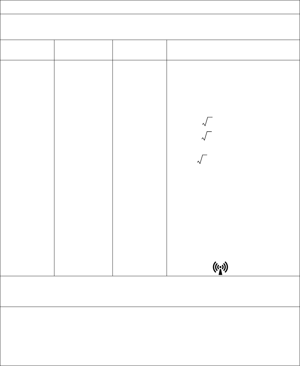
ExpressionMR400InstructionsforUseImportantInformation1‐11
Guidance and Manufacturer’s Declaration - Electromagnetic Immunity
The Expression MR400 MRI Patient Monitoring System is intended for use in the electromagnetic environment
specified below. The customer or the user of the Expression MR400 MRI Patient Monitoring System should assure that
it is used in such an environment.
Immunity Test IEC 60601 Test
Level
Compliance
Level Electromagnetic Environment - Guidance
Conducted RF
IEC 61000-4-6
Radiated RF
IEC 61000-4-3
3 Vrms
150 KHz to 80 MHz
3 V/m
80 MHz to 2.5 GHz
V1 = 3 Vrms
E1 = 3 V/m
Portable and mobile RF communications equipment
should not be used no closer to any part of the
Expression MR400 MRI Patient Monitoring System,
including cables, than the recommended separation
distance calculated from the equation applicable to
the frequency of the transmitter.
Recommended separation distance
d = (3.5/V1)
d = (3.5/E1)
(80 MHz to 800 MHz)
d = (7/E1)
(800 MHz to 2.5 GHz)
Where P is the maximum output power rating of
the transmitter in watts (W) according to the
transmitter manufacturer and d is the recom-
mended separation distance in meters (m).
Field strengths from fixed RF transmitters, as
determined by an electromagnetic site survey,a
should be less than the compliance level in each
frequency range.b
Interference may occur in the vicinity of equipment
marked with the symbol.
• At 80 MHz and 800 MHz, the higher frequency range applies.
• These guidelines may not apply in all situations. Electromagnetic propagation is affected by absorption and
reflection from structures, objects and people.
a Field strengths from fixed transmitters, such as base stations for radio (cellular/cordless) telephones and land mobile radios,
amateur radio, AM and FM radio broadcast and TV broadcast cannot be predicted theoretically with accuracy. To assess the
electromagnetic environment due to fixed RF transmitters, an electromagnetic site survey should be considered. If the measured
field strength in the location in which the Expression MR400 MRI Patient Monitoring System is used exceeds the applicable RF
compliance level above, the Expression MR400 MRI Patient Monitoring System should be observed to ensure normal operation. If
abnormal performance is observed, additional measures may be necessary, such as re-orienting or relocating the Expression MR400
MRI Patient Monitoring System.
b Over the frequency range 150 KHz to 80 MHz, field strengths should be less than 3 V/m.
P
P
P

1‐12ImportantInformationExpressionMR400InstructionsforUse
Using Batteries Safely
Batterieshavelifecycles.Thebatterylifeisatanendwhentheequipmentoperatingtime
providedbybatterypowerbecomesmuchshorterthanusual(i.e.,whenthetotalbattery
capacityhasonly70percentitsinitialcapacity).Foroptimalbatterylife,pleasefollowthese
guidelines:
•Donotstorethebatteriesinadischargedcondition.Alwayschargeabatterytoatleast40
percentofcapacitybeforestoring.
•Chargethebatteriesonceamonthwhennotinuse.
Immediatelyremoveanybatterythathasanexpiredlifecycleandreplaceitwithanewbattery
ofthesametype.(Refertopage1‐37forpartnumbers.)Toensurethesafetyofoperatorsand
patients,observethefollowingwarningsandcautions.
Recommended Separation Distances between Portable and Mobile RF Communications Equipment
and the Expression MR400 MRI Patient Monitoring System
The Expression MR400 MRI Patient Monitoring System is intended for use in an electromagnetic environment in
which radiated RF disturbances are controlled. The customer or the user of the Expression MR400 MRI Patient
Monitoring System can help prevent electromagnetic interference by maintaining a minimum distance between
portable and mobile RF communications equipment (transmitters) and the Expression MR400 MRI Patient Monitoring
System as recommended below, according to the maximum output power of the communications equipment.
Rated Maximum Output
Power Of Transmitter
(W)
Separation Distance According To Frequency Of Transmitter (m)
150 KHz to 80 MHz
d = (3.5/V1)
80 MHz to 800 MHz
d = (3.5/E1)
800 MHz to 2.5 GHz
d = (7/E1)
0.01 0.117 0.117 0.233
0.1 0.369 0.369 0.738
1 1.167 1.167 2.333
10 3.689 3.689 7.379
100 11.667 11.667 23.333
For transmitters rated at a maximum output power not listed above, the recommended separation distance d in
meters (m) can be estimated using the equation applicable to the frequency of the transmitter, where P is the
maximum output power rating of the transmitter in watts (W) according to the transmitter manufacturer.
• At 80 MHz and 800 MHz, the separation distance for the higher frequency range applies.
• These guidelines may not apply in all situations. Electromagnetic propagation is affected by absorption and
reflection from structures, objects and people.
P
P
P

ExpressionMR400InstructionsforUseImportantInformation1‐13
Warning
WARNING
Do not use a damaged battery. Periodically check batteries, stop using and replace any
battery that exhibits abnormal heat, odor, color, deformation, or other condition. If a battery
is punctured or if battery liquid leaks onto your skin or clothing, immediately wash the area
and clothing with fresh water. If battery liquid gets into your eyes, do not rub your eyes;
immediately flush your eyes with clean water and consult a physician.
Caution
CAUTIONS
• If the battery contacts become dirty, wipe them clean with a dry cloth before use. Do not
immerse in a battery in water or other liquids.
• Store batteries in a dry place, between 0 to 40°C (32 to 104°F) . Do not expose a battery to
temperatures above 60°C (140°F).
• Do not short the external battery contacts. Keep metal objects away from the battery
contacts.
• Store each battery in a manner that prevents shorting with the container or another cell/
battery.
• Only use the Philips specified charger.
Examining the Shipment
Toreportshippingdamage,ortoresolveanyissuesorconcernswithyourorder,contact
CustomerService.(Saveallpackingmaterialsandrelatedshippingdocuments,asthesemaybe
requiredtoprocessashippingdamageclaimwiththecarrier.)
Afterremovingthecontentsfromtheshippingcontainers,carefullyexamineallitemsforsignsof
damagethatmayhaveoccurredduringshipment.Also,checkallitemsagainsttheincluded
packinglistandthepurchaserequest.
Thecontentsofthecrateshouldinclude:
• ExpressionMR400MRIPatientMonitoringSystem
•Twomainbatteries
•InstructionsforUse(IFU)manual
•QuickReferenceGuide(includedinEnglish‐localizedshipmentsonly)
•PowerCord
Aseparatecontainermayincludeadditionalitems:
• WirelessECGpatientmodule(Gen3)
• WirelessSpO2patientmodule(Gen3)

1‐14ImportantInformationExpressionMR400InstructionsforUse
•Modulebatterycharger
•Modulebatteries
Disposing of the Packaging
Thepackagingcanberetainedforfutureuse.Otherwise,thepackagingforthesystem(whichis
madeofrecyclablematerialsthatincludecorrugatedpaper,polyethylene[PE]foamandplastic)
maybesubjecttodisposalregulationsforuserandenvironmentalsafety.Fordisposal,itmaybe
necessarytoseparatethesematerialsbytype.Alwaysobserveandadheretoyourcurrentlocal
regulationswhendisposingofthepackagingmaterial.
Initial Setup
Theinstructionsbelowdetailtheinitialsetupprocessforafully‐equippedExpressionMR400MRI
PatientMonitoringSystem(hereafterreferredtoastheMR400)—includingthewirelessECG
patientmodule(hereafterreferredtoasthewECGmodule)andthewirelessSpO2patient
module(hereafterreferredtoasthewSpO2module)andhereafterreferredtocollectivelyas
wirelessmodules.
DependingupontheneedsofyourfacilityandtheMR400optionspurchased,thestepsyou
followmaydifferandsomemaynotberequired.Forthelocationofcomponentsnotdetailed
below,seechapter2.
WARNINGS
• Only perform initial setup of the MR400 at a location outside of the MR magnet room.
Failure to observe this warning may result in serious injury.
• No modification of this equipment is allowed. Failure to observe this warning may
result in serious injury.
CAUTION
The MR400 and accessories must be used and stored according to the environmental
specifications detailed in Appendix A. Failure to adhere to the specified environmental
requirements may affect system and/or accessory performance and accuracy.

ExpressionMR400InstructionsforUseImportantInformation1‐15
ToperforminitialsetupoftheMR400
Step Action
1PerformavisualinspectionoftheMR400,checkingforlooseor
missinghardwareordamage.
Iflooseormissinghardwareordamageisobserved,contact
technicalsupport.
2Installthemainbatteriesintothecartandconnectthereserve
batteries;seepage1‐16.
3ConnectACmainspowertotheMR400,butDONOTturnonthe
powerswitch.Allowthebatteriestochargeforatleast12hours
beforeuse;seepage1‐20.
Note
Before initial use, charge the batteries in the cart for at least 12
hours with the MR400 turned off and connected to AC mains power.
4IfwECGandwSpO2moduleswereincluded,performavisual
inspectionofthedevicesforlooseormissinghardwareordamage.
5IfawSpO2modulewasincluded,attachanSPO2probetoit;see
page1‐18.
6Ifmodulebatterieswereincluded,chargethemodulebatteries
usingthePhilips‐specifiedbatterycharger.(Refertothe
instructionsprovidedwiththecharger.)
Note
Before initial use, charge the module batteries for at least 4 hours.
7Pressthepowerswitch(onthefrontofthecart)thenverifythatthe
MR400hassuccessfullypowered‐upandthatthepowerLEDis
steadygreen.
Forotherpossibleindications,seepage2‐7.
8IfequippedwithanIP5,verifythattheMR400andIP5aresettothe
samewirelessnetworkchannelbycheckingthenetworkicon(see
examplesbelow)thatisdisplayedbyeachdevice.
Seepage1‐27forMR400networksettinginstructions;and,referto
theIFUfortheIP5fornetworksettinginstructions.
9IfwECGandwSpO2moduleswereincluded,installthecharged
modulebattery(orbatteries)intothedevice(s);seepage1‐24for
thewECGmoduleandseepage1‐26forwSpO2module.
1‐16ImportantInformationExpressionMR400InstructionsforUse
Installing and Connecting Cart Batteries
Warning
WARNING
Cart batteries contain ferrous materials that are attracted to the MR magnetic field. Do not
install or remove the cart batteries when closer than the 1,000 gauss (0.1 T) field line, as
measured from the center line of the MR bore to the MR400. The batteries will be attracted
to the magnetic field, possibly causing patient or user injury.
CAUTION
Never force a main battery into a battery compartment as it will damage the battery and/or the cart.
FourbatteriesareusedintheMR400:
•Twomainbatteriesmustbeinserted—oneintotheleftbatterycompartmentandoneinto
therightbatterycompartmentofthecart;and,
•Tworeservebatteries,internally‐housedinthecart,mustbeswitchedon.
Toinstallandconnectthemainandreservebatteries
10 VerifythatthestatusindicatoronthewECGandwSpO2modulesis
illuminatedsteadygreen:
•ForthewECGmodule,seepage2‐9.
•ForthewSpO2module,seepage2‐11.
11 VerifythatthewirelessnetworkchannelsonthewECGandwSpO2
modulesaresettothechannelusedbytheMR400;seepage1‐29.
12 PlacethewECGandwSpO2modulesintothemoduleholderson
theMR400;seepage2‐12.
Thiscompletestheinitialsetupprocess.Forinformationregarding
otherpossibleMR400connections;seeRearPanelConnectionson
page1‐19.
Step Action
Step Action
1Locatethebatterycompartments,whichareunderneaththeWPU
ontheleftandrightsidesofthecart.
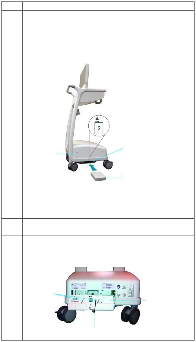
ExpressionMR400InstructionsforUseImportantInformation1‐17
2Holdamaincartbatterywiththelabelsidedownandwithits
connectorfacingforward.(Silkscreeningaboveeachbattery
compartmentprovidesthecorrectbatteryorientation—theleft
sideisshownintheexamplebelow.)Then,slidethebattery
completelyintothebatterycompartmentuntila“click”isheardas
thebatterylatchesintoplace.
(Ifthebatterydoesnotlatchintoplacewheninserted,thenitis
notproperlyoriented.Inthiscase,remove,reorientcorrectly,and
thenreinsertthebattery.)
3Repeatsteps1and2toinstalltheremainingmaincartbatteryon
theoppositesideofthecart.
4 Removetheshieldcapfromthegatingconnectorandthetwo
screwsthatsecuretheservicepanelcovertothebackoftheWPU
thenremovetheservicepanelcover.
Step Action
Main cart battery
Battery compartment
WPU
Screws
Service panel
cover
Shield cap
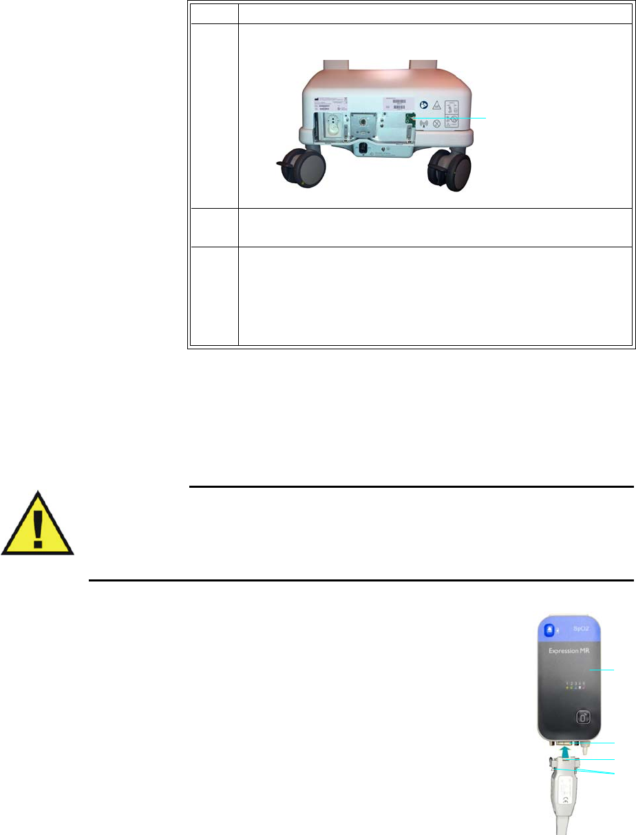
1‐18ImportantInformationExpressionMR400InstructionsforUse
Attaching the SpO2 Probe to the wSpO2 Module
TheSpO2probe,necessaryfortakingSpO2‐relatedmeasurementsusingthewSpO2module,
mustbeconnectedprioruse.
WARNINGS
• Only perform this attachment at a location outside of the MR magnet room. Failure to
observe this warning may result in serious injury.
• Connecting an other than specified SPO2 probe to the wSpO2 module can cause
inaccurate SPO2 readings and damage the module.
ToattachtheSPO2probe
InserttheSPO2probeconnectorintotheDB‐9connectoronthewSpO2
modulethensecurelytightenbothscrews.
5LocatethebatteryswitchandtoggleitintotheOn(I)position.
6 Reinstalltheservicepanelcover,andsecureittotheWPUusing
thetwoscrews.
7Replacetheshieldcap.
Thiscompletestheinstallationandconnectionofthemainand
reservebatteries.ConnectACmainspowerthenallowthese
batteriestochargeforatleast12hoursbeforeinitialuse;seepage
1‐21.
Step Action
Battery switch
1wSpO2 module
2DB-9 connector
3SPO2 probe connector
4Screws
3
4
2
1
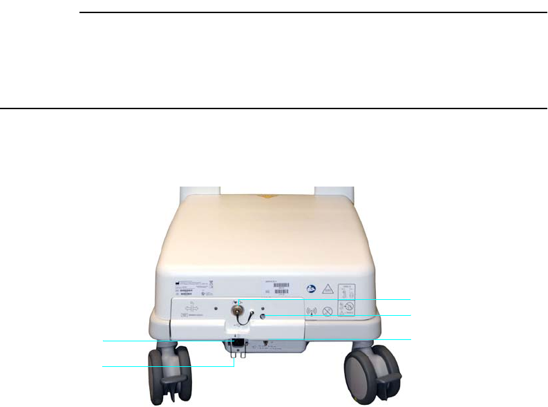
ExpressionMR400InstructionsforUseImportantInformation1‐19
Rear Panel Connections
DependingupontheoptionsincludedwithyourMR400ortheusemodel,someconnectionsmay
berequiredaftermovingtheMR400intotheMRmagnetroom.Inadditiontotheconnectionfor
ACmainspower,connectionsforthewastegasportandthegatingcableareavailableonthe
rearpaneloftheMR400.(ForinformationabouttheplacementoftheMR400intheMRmagnet
room,seepage3‐2.)
CAUTION
When making connections to the rear panel of the MR400, ensure that the final installation
complies with IEC 60601-1, clause 16, Medical Electrical (ME) Systems, to assure operator and
patient safety. Always check the summation of leakage currents when the MR400 is connected to
additional external equipment.
Wheretheintegrityoftheexternalprotectiveconductorintheinstallationoritsarrangementis
indoubt,theMR400shallbeoperatedfrombatteries.
1 Gating connector for gating control connections to the MR
system. (Gating cables are type-dependent; see page 1-35.)
2Waste gas port (if equipped) for connection of exhausted sam-
pled respiratory gases from the MR400 to your facility’s gas scaveng-
ing system; suggested tubing requirement: 3.175 mm (0.125 inch)
outer diameter, 1.6 mm (0.063 inch) inner diameter.
3 Ground lug (equipotential ground [earth] connection point)
• allows for electrical safety testing; and,
• allows authorized service personnel to connect a ground
strap for prevention of ESD during servicing.
1
2
3
4
5

1‐20ImportantInformationExpressionMR400InstructionsforUse
Connecting AC Mains Power
WhenconnectingtheMR400tothemainselectricalsupply,donotroutethedetachablepower
cordwhereitwillbeanobstructionorsteppedupon.DonotblockaccesstotheMR400with
otherequipmentandneverpositiontheMR400insuchawaythatwouldmakeitdifficultto
unplug.
WARNINGS
• Only use the supplied power cord and connect to properly grounded AC outlets to
avoid electrical shock.
• Avoid use of electrical extension cords or multiple portable socket outlets, which may
create a safety hazard by compromising the grounding integrity of the MR400.
ToconnectACmainspower
ToremovetheMR400fromACmainspower
PulltheplugofpowercordfromtheACwalloutlet.Then,liftthestrainreliefandremovethe
powercordfromtheACreceptacleontherearoftheMR400.Storethecordinasafeplace.
4Strain relief for retention of the power cord.
5AC receptacle for connection of the power cord.
Step Action
1Ensurethatallcartbatteriesareinstalledandswitchedon;see
page1‐16fordetails.
2IfplacingtheMR400intheMRmagnetroom,positiontheMR400
ataproperlocation;seepage3‐2.
3Raisethestrainrelief;seepage1‐20forthelocation.
4PlugthepowercordintotheACreceptacleontheMR400;see
page1‐20forthelocation.
Foraddedmobility,thepowercordextension(REF989803168221)
canalsobeconnected.
5Lowerthestrainreliefoverthepowercord.
6PlugthepowercordintoanapprovedACmainsoutlet.

ExpressionMR400InstructionsforUseImportantInformation1‐21
Understanding Battery Operations
Cart Batteries
Warning
WARNING
Do not touch the patient and the circuitry in the battery compartments of the MR400
simultaneously.
Cartbatteries,wheninstalled(main)andswitchedon(reserve),arechargedandconditionedby
anintegratedchargingsystem.WhenturnedonandconnectedtoACmains,theMR400operates
fromACpowerandsimultaneouslychargesallcartbatteries.Whenturnedoffandconnectedto
ACmains,batterychargingfunctionscontinue.
Ifatanytime,ACmainsislost,theMR400willautomaticallyswitchtobatterypowertoprovide
uninterruptedservice—then,whenACmainsisrestored,theMR400willautomatically,without
delay,revertbacktoACpowerfunctions.IfthereservebatteriesarefullydepletedandACmains
islost,thentheunitwillpoweroff.
TheMR400’smaximumoperatingtimeonbatterypowerdependsupontheenabledparameters
andthetypeandfrequencyofmonitoringfunctions(seetheBattery,OperationTimeonpageA‐4
foralisting).
Charging Cart Batteries
Cartbatteriesmustbechargedbeforeinitialuse.Duringinitialsetuporwheninstallingnew
batteries,chargethecartbatteriesforatleast12hourssothattheyarefullychargedand
conditionedforoperation.
Notes
• Use only with the specified battery charger.
• The main batteries must always be inserted and the reserve batteries must always be
switched on to prevent loss of patient monitoring during a power outage. If main batteries
are not inserted and if the reserve batteries are not switched on, then during power outage
unsaved user settings will revert to factory defaults.
• We recommend plugging the MR400 into a backup generator or equivalent means to
prevent a lapse in patient monitoring during a power loss.
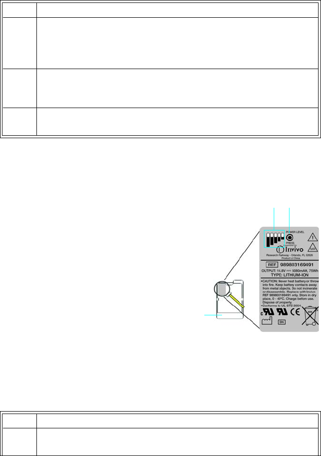
1‐22ImportantInformationExpressionMR400InstructionsforUse
Tochargethecartbatteries
Chargedcapacityofallcartbatteriescanbedisplayed;seetheStatusInformationPanelonpage
2‐18).
Chargedcapacitycanalsobefoundbypressingthepowerlevel
buttononeachmaincartbattery,wherethecurrentlevelis
providedbythechargeindicator;seeRemovingCartBatteries,
below.
Removing Cart Batteries
Toremovethemainbatteries
Step Action
1Ensurethatallcartbatteriesareinstalledandswitchedon.
SeeInstallingandConnectingCartBatteriesonpage1‐16for
details.
2ConnecttheMR400toACmainspower.
SeeConnectingACMainsPoweronpage1‐20.
3EnsurethattheMR400isturnedoffandthatitremainsoffforthe
next12hours.
1Charge indicator
2Power level button
3Cart battery
12
3
Step Action
1Locatethebatteryejectbutton,whichisinarecessedareaunder
eachbatterycompartmentontheleftandrightsidesofthecart.
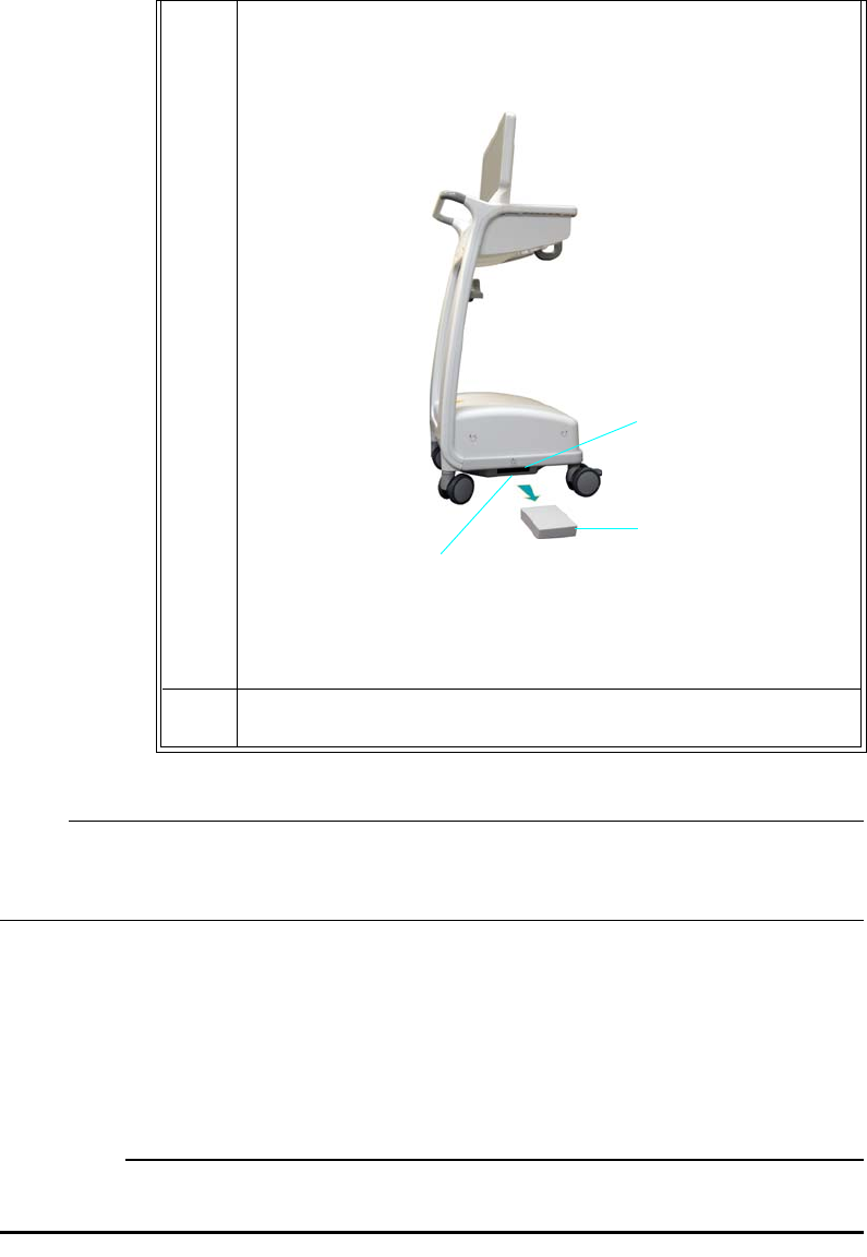
ExpressionMR400InstructionsforUseImportantInformation1‐23
Note
The reserve batteries cannot be removed, but can be switched off. For instructions on the complete
removal of power to the MR400, see page 14-2.
Wireless Module Batteries
ModulebatteriesprovidepowertothewECGandwSpO2modules.Modulebatteriesare
interchangeable,non‐magnetic,andcanbehandledsafelyintheMRmagnetroom.
CAUTION
To minimize the chance of image artifacts, never place module batteries in the MRI field of view.
2Pressthebatteryejectbuttontopartiallyejectamainbatteryfrom
thebatterycompartment,andthengraspthebatteryandpullto
removeitcompletelyfromtheMR400.
(Ifthebatterydoesnotrelease,applyaslightforwardpressureto
thebatterywhilepressingthebatteryejectbutton.)
3Repeatsteps1and2toremovetheothermaincartbatteryonthe
oppositesideoftheMR400.
Main battery
Battery compartment
Battery eject button
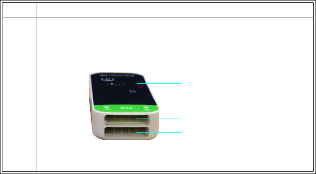
1‐24ImportantInformationExpressionMR400InstructionsforUse
Charging Module Batteries
Modulebatteriesmustbechargedforatleast4hoursbeforeinitialuse.Modulebatteriesare
chargedinthePhilips‐specifiedbatterycharger.Refertotheinstructionsprovidedwiththis
batterychargerforinformation.
Installing Batteries in the wECG Module
ThewECGmodulecanacceptuptotwobatteries.Dependinguponthenumberofbatteries
installed,thewECGmoduleprovidedifferentoperationalfeatures:
•Ifonebatteryisinstalled,thenthewECGmodulewillturnonandfunctionnormally—but
beforeitschargeisexhausted,asecondbatterymustbeinstalledinordertocontinuethe
ECGstudy.
•Iftwobatteriesareinstalled,thenseamlessoperationispossible—onebatterywillprovide
poweruntilitschargeisexhausted,atwhichtimethewECGmodulewillautomatically
switchtotheremainingbatteryforcontinuedoperation.Aslongassufficientpoweris
providedbythesecondbattery,continuedoperationispossible.And,anexhausted
batterycanbereplacedatanytimewithoutinterruptiontotheECGstudy,providedthat
sufficientchargeispresentontheremainingbattery.
•IndicatorsidentifythesourcebatterybeingusedbythewECGmodule;seepage2‐9.
•Whenbothbatteriesareremoved,thewECGmodulewillturnoff.
ToinstallbatteriesinthewECGmodule
Step Action
1HoldthewECGmodulesothatitsbatterybaysareorientedas
shown,withbatterybay1inthelowerpositionandbatterybay2
intheupperposition.
wECG module
Bay 1
Bay 2
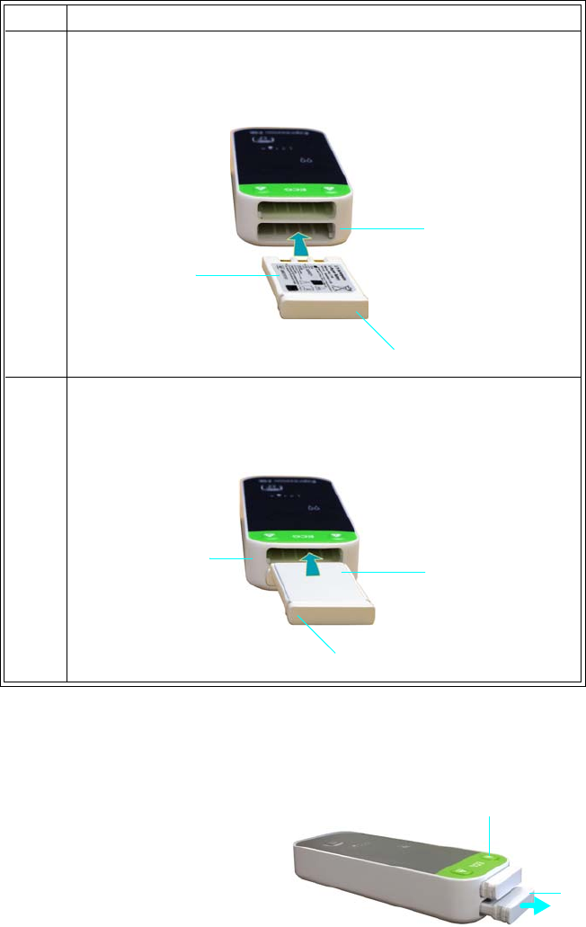
ExpressionMR400InstructionsforUseImportantInformation1‐25
Removing Batteries from the wECG Module
Toremovebattery1fromthewECGmodule
Pressabatteryejectbutton1(item1,right).Then
graspthepartiallyejectedmodulebattery(item2)
andpulltoremoveit.
2Orientamodulebatterysothatthetipofthebatteryarrowaligns
withthetipofthebay1arrowonthewECGmodule.Thenslidethe
modulebatteryintobay1,pressinguntilitseatscompletely.
3Orientamodulebatterysothatthetipofthebatteryarrowaligns
withthetipofthebay2arrowonthewECGmodule.Thenslidethe
modulebatteryintobay2,pressinguntilitseatscompletely.
Step Action
Module battery
Bay 1 arrow
Battery arrow
Module battery
Bay 2 arrow
Battery arrow
1
2
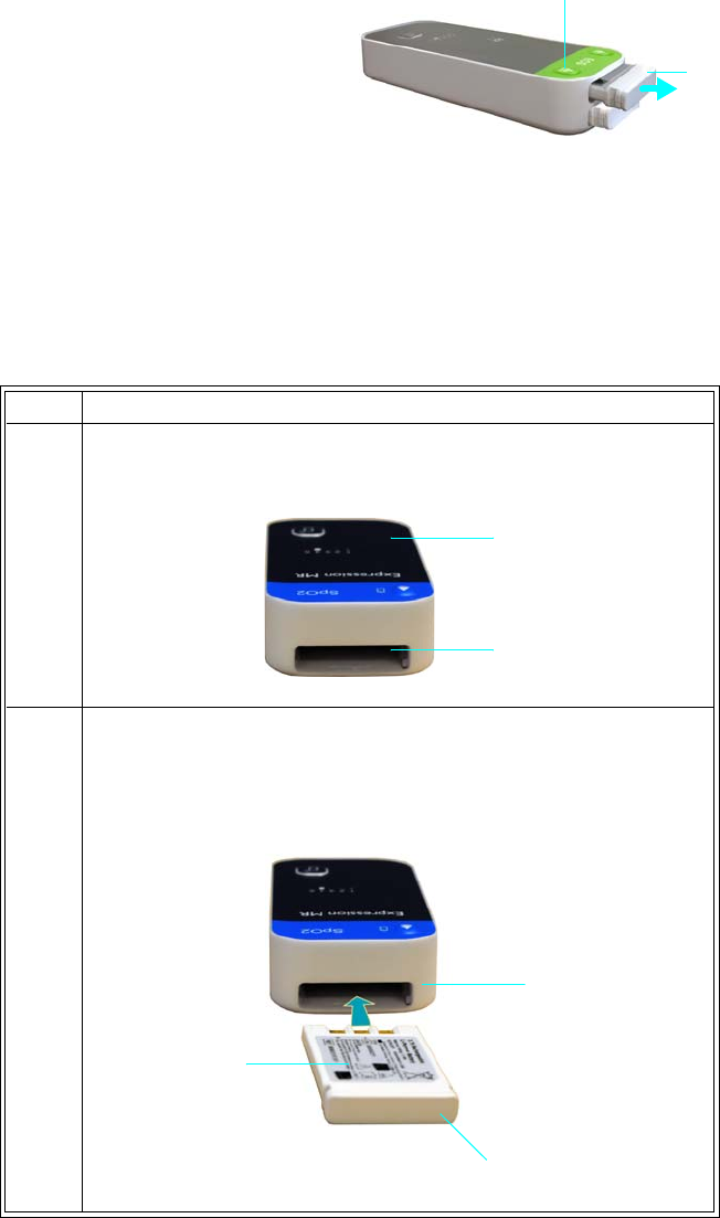
1‐26ImportantInformationExpressionMR400InstructionsforUse
Toremovebattery2fromthewECGmodule
Pressabatteryejectbutton2(item3,right).Then
graspthepartiallyejectedmodulebattery(item4)
andpulltoremoveit.
Installing a Battery in the wSpO2 Module
ThewSpO2moduleusesonebattery.Whenamodulebatteryisinserted,thewSpO2modulewill
turnon.And,whenthebatteryisremoved,thewSpO2modulewillturnoff.
ToinstallabatteryinthewSpO2module
3
4
Step Action
1HoldthewSpO2modulesothatitsbatterybayisorientedas
shown.
2Orientamodulebatterysothatthetipofthebatteryarrowaligns
withthetipofthebayarrowonthewSpO2module.Thenslidethe
modulebatteryintothebatterybay,pressinguntilitseats
completely.
wSpO2 module
Battery bay
Module battery
Bay arrow
Battery arrow
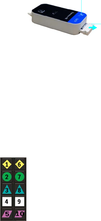
ExpressionMR400InstructionsforUseImportantInformation1‐27
Removing the Battery from the wSpO2 Module
ToremovethebatteryfromthewSpO2module
Pressthebatteryejectbutton(item1,right).Then
graspthepartiallyejectedmodulebattery(item2)
andpulltoremoveit.
Understanding Wireless Network Operations
AwirelessnetworkchannelisusedforsystemcommunicationbetweentheMR400cartandthe
wECGandwSpO2modules(and,ifequipped,theIP5).Allwirelessdevicesmustusethesame
wirelessnetworkchannelforpropersystemcommunications.Also,wheremultipleInvivo(Royal
Philips)MRIpatientmonitoringsystemsareinuse,theselectedwirelessnetworkchannelshould
benotusedbyanyothersysteminyourfacility(forthefrequencyrange,seepage1‐8).
Setting the Wireless Network Channel of the Cart
AllcontrolsforselectingthewirelessnetworkchanneloftheMR400arelocatedonthecart’s
touchscreen.Uniquesymbolsandnumbersareusedtoidentifyeachavailablechannelforthe
MR400,asshownbelow.
2
1
Network channel 1 Network channel 6
Network channel 2 Network channel 7
Network channel 3 Network channel 8
Network channel 4 Network channel 9
Network channel 5 Network channel 10
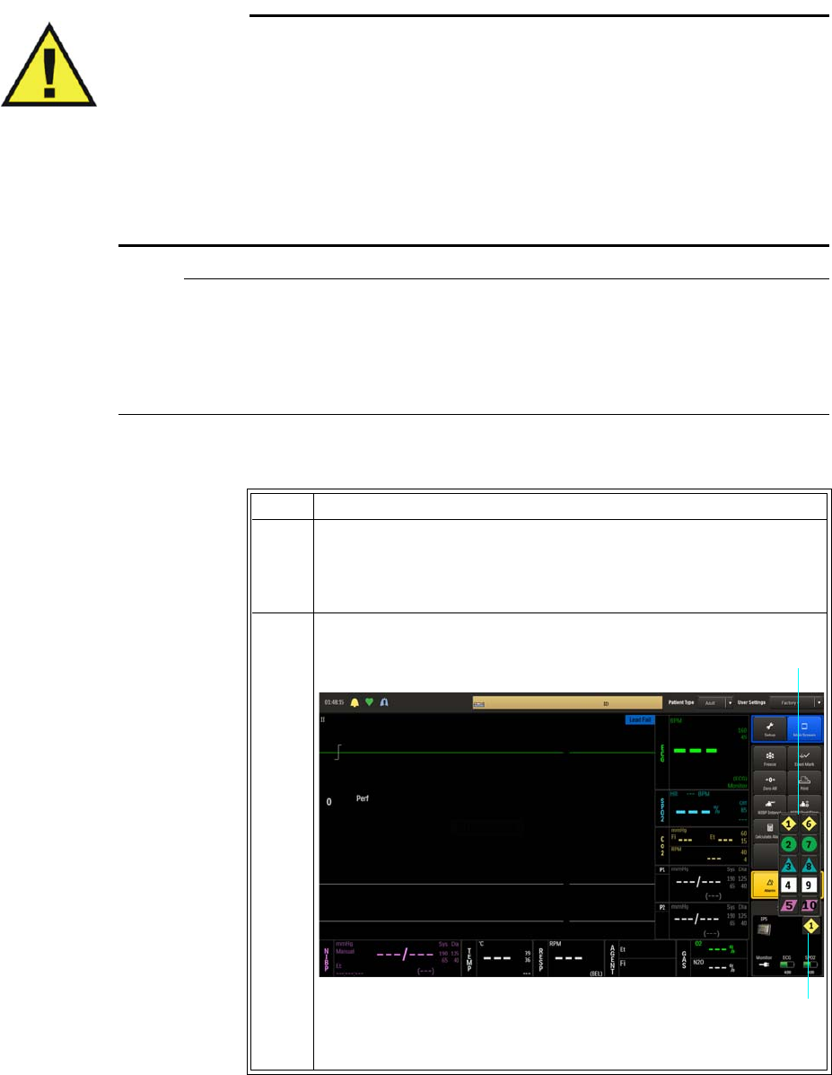
1‐28ImportantInformationExpressionMR400InstructionsforUse
WARNINGS
•Care should be taken to guard against inadvertent changes to the network channel
setting. Before use, always ensure that all devices are communicating properly. Failure
to do so may cause a lapse in patient monitoring.
• An MR400 system is comprised of one MR400 cart, one wECG module, and one
wSpO2 module, and optionally an IP5. In environments where multiple MR400 MRI
patient monitoring systems are being used, you must be aware of each component’s
network setting. Operating multiple MR400 systems on the same network or with a
wrong network setting will interfere with communications, and incorrect or corrupted
patient vital signs information will be displayed as a result.
Notes
• If a patient is currently admitted, a warning dialog box will prompt you before a change to
the monitor network is allowed.
• After changing the wireless network channel of the MR400, you must wait a minimum of 5
seconds before removing power from the system; otherwise, the change will be lost.
TosetthewirelessnetworkchannelfortheMR400cart
Step Action
1Pressthepowerswitch(seepage2‐7forthelocation)thenallow
theMR400toinitialize.
Themainscreenappears.
2 Selectthenetworkicon.
Thenetworkmenuappears.
Network icon
Network menu
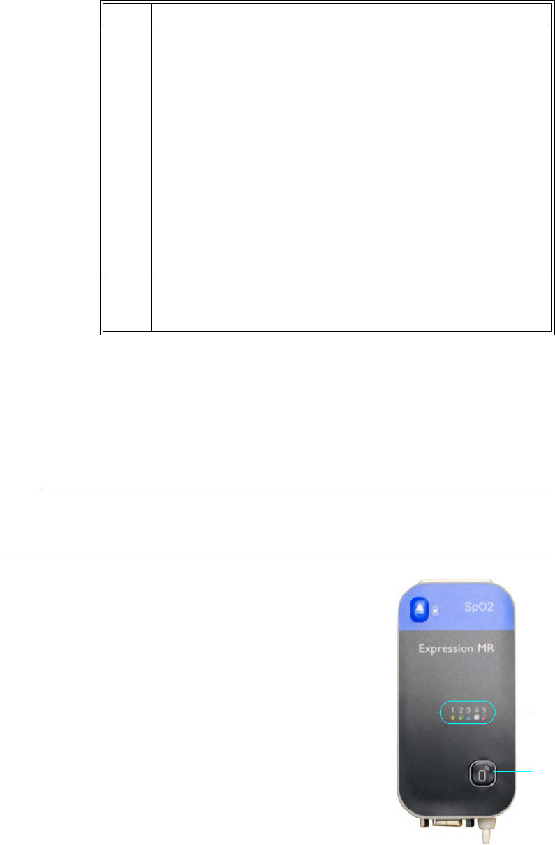
ExpressionMR400InstructionsforUseImportantInformation1‐29
Setting the Wireless Network Channel of the wECG and wSpO2 Modules
Allindicatorsandcontrolsforwirelessnetworkchannelselectionarelocatedonthefrontofthe
wirelessmodules.Twodifferentgroupsoffivewirelessnetworkchannelsareavailable(channels
1–5,orchannels6–10)andbothmodulesmustbeofthesamegroup,dependinguponyour
selectionattimeofpurchase.
Note
The wECG and wSpO2 modules may arrive preprogrammed to match the network channel setting
of your MR400, thus eliminating the need to change the channel setting.
Thewirelessnetworkchannelforamoduleischangedbyusingthe
networkselectionbutton.Thewirelessnetworkchannelfora
moduleshouldbesettomatchthewirelessnetworkchannelused
bytheMR400;seepage1‐27.
Thefollowingdirectionsforchangingthewirelessnetworkchannel
applytobothwirelessmodulesandtoeitherchannelgroup,though
theprocessbelowdepictsthewSpO2moduleandchannelgroup1–
5.(FormoreoperationaldetailsaboutthewECGmodule,seepage
2‐9;and,forthewSpO2module,seepage2‐11.)
3 Selectthedesiredsettingfromtheoptions:
1
2
3
4
5
6
7
8
9
10
Thesettingisenteredandthenetworkiconischangedtothe
currentselection.
4EnsurethatthenetworkchannelusedbythewECGandwSpO2
modules(seepage1‐29)andtheIP5(ifequipped)areidenticalto
thenetworksettingofthecart.
Step Action
1Network channel indicators
2Network selection button
2
1
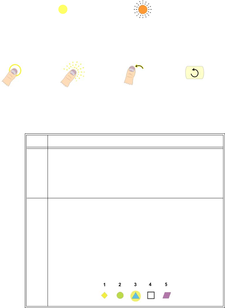
1‐30ImportantInformationExpressionMR400InstructionsforUse
Beforestartingtheproceduretochangethenetworkchannelofthewirelessmodule,takenoteof
theseconventionsthatareusedtoexplaintheprocess:
•Thefollowingsymbolsareusedtoconveythestateofthenetworkchannelindicatorona
wirelessmodule.
•Thefollowingillustrationsareusedtoconveyactionsconcerningtheuseofthenetwork
selectionbutton.
TosetthewirelessnetworkchannelofthewECGorwSpO2module
Symbolilluminated Symbolblinking
Pressingthe
button
Pressingandholding
thebutton
Releasingthe
button
Repeating
Step Action
1Turnoffthewirelessmodule:
•wECGmodule—seeRemovingBatteriesfromthewECG
Moduleonpage1‐25.
•wSpO2module—seeRemovingtheBatteryfromthewSpO2
Moduleonpage1‐27.
2Turnonthewirelessmodule:
•wECGmodule—seeInstallingBatteriesinthewECGModule
onpage1‐24.
•wSpO2module—seeInstallingaBatteryinthewSpO2
Moduleonpage1‐26.
Thenetworkchannelindicatorswillflashbrieflyandthenthe
currentnetworkchannelindicatorwillilluminate(forexample,“3”
intheillustrationbelow).
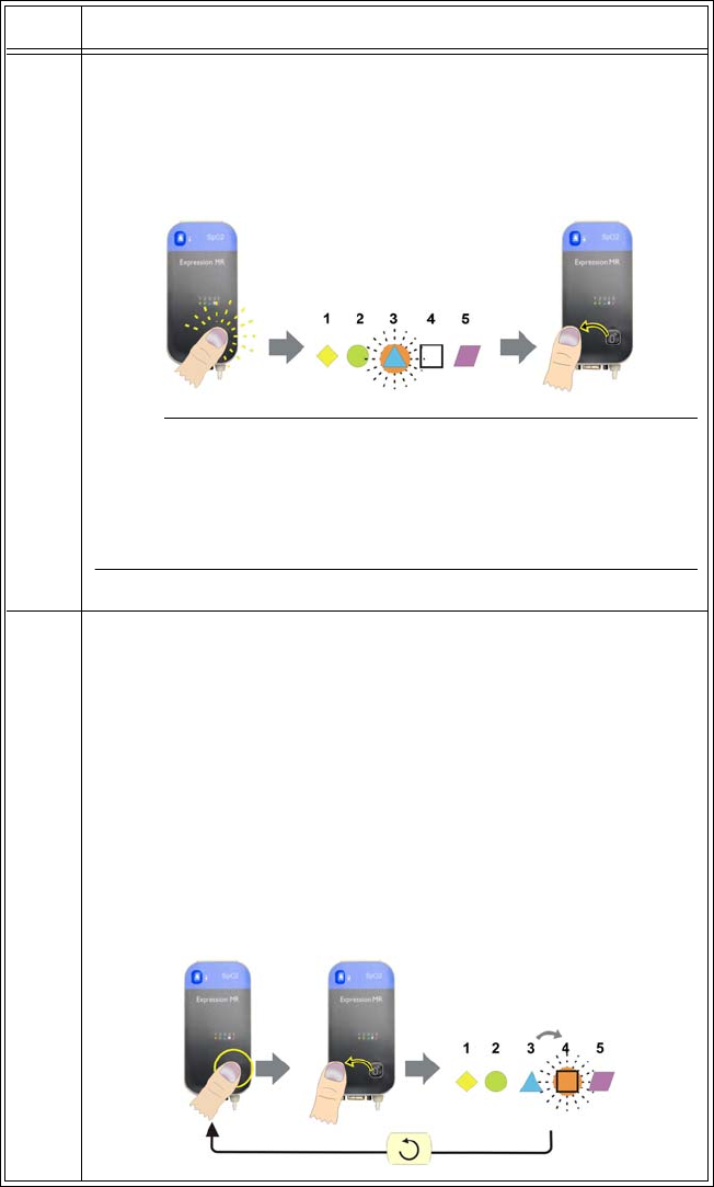
ExpressionMR400InstructionsforUseImportantInformation1‐31
3 Enterthenetworkchannelchangemode:Afterthecurrent
networkchannelindicatorhasbeenilluminated(andwithin10
secondsofmodulepower‐up),pressandholdthenetwork
selectionbuttonuntilthecurrentnetworkchannelindicatorbegins
torapidlyblinkthenreleasethebutton.
Note
If the network channel change sequence was not started within 10
seconds after the module has been turned on, network channel
changes will not be allowed. In this case, you must cycle module
power and restart the sequence.
4Pressdownagainonthenetworkselectionbuttonuntilthesymbol
stopsblinkingandthenreleasethebuttontochangethenetwork
channelsetting.
Whenyoudothis,thenextnetworkchannelindicatorinthe
sequencewillblinkrapidly.(Inotherwords,ifthemodulewas
originallyusingnetworkchannel“3,”nowthe“4”symbolwillbe
blinking.)Repeatthissequenceofpressingdownandreleasingthe
buttonuntilthesymbolofthenetworkchannelyoupreferis
rapidlyblinking.Ifyoupassthedesiredchannel,simplycontinue
pressingandreleasingthebuttonuntilthedesirednetwork
channelindicatorisblinkingagain.
Step Action
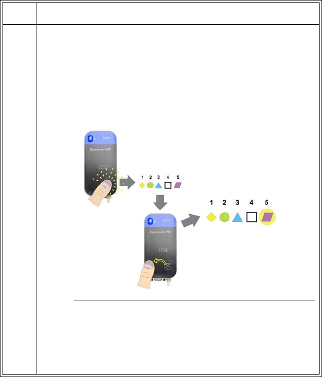
1‐32ImportantInformationExpressionMR400InstructionsforUse
5Whenyoureachthedesiredsymbol,pressandholdthebuttonfor
approximately5secondstolockandsavethenewsetting.
Theselectednetworkchannel'ssymbolwillturnoffwhilethe
buttonisdepressed.Thenitwillilluminate(notblink)whenthe
newnetworkchannelsettingissaved.Onceilluminated,release
thebutton.Themodulewillbeginusingtheselectednetwork
channel.
Note
Any part the network channel change sequence not completed will
cause the module to revert to the network channel previously set 30
seconds after the network selection button was last released.
Step Action
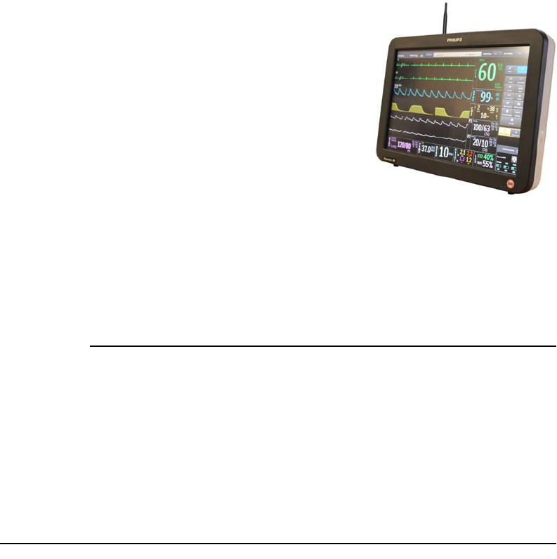
ExpressionMR400InstructionsforUseImportantInformation1‐33
Advanced User Options
Expression Information Portal (Model IP5)
ProvidingsystemcontroloutsidetheMRmagnetroom,the
ExpressionInformationPortal(ModelIP5),hereafterreferred
toastheIP5,isawirelessdevicethatalsofeaturesprinting
capabilitiesandHL7dataoutputoptions.
TheMR400usesawirelessconnectionforcommunication
withtheIP5.TheIP5’sconnectiontothehospitalinformation
system(HIS)isexplainedindetailintheIP5IFU.Whenusing
theIP5toconnecttotheHIS,adheretoallcautionsandsafety
instructionsfoundintheIP5IFU.
Additional Options
Additionaloptionsmaybesuggestedbyyourbiomedicaltechniciantoincreaseuserease.
Consultyourbiomedicaltechnicianortechnicalsupportwithspecificrequests.
Caution
CAUTIONS
• When adding equipment to an MR400 system (for example, an IP5), be aware that all
devices should be at the same or a compatible software revision level. Contact technical
support if you have questions or to upgrade software. Failure to observe this requirement
could result in compatibility conflicts, communication problems, et cetera.
• Unauthorized modification to the radios/and/or antennas may cause the device to no longer
be in compliance with applicable regulatory standards
• The manufacturer is not responsible for any radio frequency interference caused by
unauthorized modifications to the radios and/or antennas within this equipment. Such
modification could inhibit proper MR400 system or device communications.
Accessory List
Accessoriesarelistedinthetablesbelowwithpartnumber(REF)information.Whereapplicable,
theoriginalpartnumberhasalsobeenincludedforreference.Foradditionalinformationabout
theseaccessories,pleaseconsultthedocumentationthataccompaniestheaccessory.
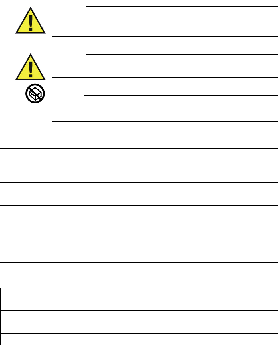
1‐34ImportantInformationExpressionMR400InstructionsforUse
Warning
WARNING
The MR400 has been validated with all of the accessories listed below. Only use these
specified accessories as other types or brands may compromise the safety and accuracy of
the MR400. Patient injury or loss of monitoring may result if incorrect accessories are used.
Warning
WARNING
Do not use sterile items if the packaging is damaged. Patient injury may result if non-sterile
accessories are used.
CAUTION
Modifications to the MR400 System during its service life are required to be evaluated to the
requirements of IEC 60601-1.
AGENT Original Part Number REF
CANNULA, DISP, ADULT 9012 989803152561
CANNULA, DISP, ADULT 9016 989803152601
CANNULA,DISP,INT INF,(DIVIDED) 9016B 989803152621
CANNULA,DISP,PED,(DIVIDED) 9016C 989803152631
CANNULA,DISP,INFANT,(DIVIDED) 9016A 989803152611
CANNULA, DISP, INT INFANT 9015 989803152591
CANNULA, DISP, PED 9013 989803152571
CANNULA, DISP, INFANT 9014 989803152581
ANESTHETIC OXYGEN (O2) SENSOR — 989803162051
KIT,DISPOSABLE WATER TRAP,3160 94012 989803152671
KIT,SAMPLE,AGENTS,3160 94018 989803152661
CO2 REF
LOFLO SAMPLE LINE, ADULT CANNULA, BOX 20 989803183241
LOFLO SAMPLE LINE, PED. CANNULA, BOX 20 989803183251
LOFLO SAMPLE LINE, NEO. CANNULA, BOX 20 989803183261
LOFLO LINE, ADU DVD CANNULA,BOX 20 989803183271

ExpressionMR400InstructionsforUseImportantInformation1‐35
LOFLO LINE, PED DVD CANNULA, BOX 20 989803183281
LOFLO LINE, ADU AIRWAY ADPT, BOX 20 989803183291
LOFLO SAMPLE LINE, ADULT CANNULA,BOX 100 989803185331
LOFLO SAMPLE LINE, PED CANNULA, BOX 100 989803185341
LOFLO SAMPLE LINE, NEO CANNULA, BOX 100 989803185351
LOFLO LINE, ADU DVD CANNULA, BOX 100 989803185361
LOFLO LINE, PED DVD CANNULA, BOX 100 989803185371
LOFLO LINE ADU AIRWAY ADPT, BOX 100 989803185381
CO2 REF
ECG Original Part Number REF
GEL, ECG/EEG, SKIN PREP, TUBE, 3-PACK 9009 989803152291
EXPRESSION MR ECG LEADS, AAMI, CV — 989803193721
EXPRESSION MR ECG LEADS, AAMI, STANDARD — 989803193731
EXPRESSION MR ECG LEADS, AAMI, NEONATAL — 989803193741
EXPRESSION MR ECG LEADS, IEC, CV — 989803193751
EXPRESSION MR ECG LEADS, IEC, STANDARD — 989803193761
EXPRESSION MR ECG LEADS, IEC, NEONATAL — 989803193771
QUADTRODE MRI ECG PAD, 25/BOX — 989803179031
ELCTRD, MRI ECG, QUTRD.CV, 25/BOX — 989803179041
ELCTRD, MRI, NEO.QUDTRD, 25/BOX — 989803179051
WIRELESS ECG PATIENT MODULE (GEN 3) 1-5 — 989803192761
WIRELESS ECG PATIENT MODULE (GEN 3) 6-10 — 989803194341
Gating Original Part Number REF
CAB, DIGITAL GATING, GE, 3160 9292 989803152821
CAB, GATING, SIEMENS, 3160 9291 989803152831
UNIVERSAL GATING INTERFACE — 989803195521
CAB, DIG.GATING, HIT/TOSH, 3160 9293 989803152851

1‐36ImportantInformationExpressionMR400InstructionsforUse
Invasive Blood Pressure REF
EXPRESSION MR IBP TRANSDUCER CABLE, 5FT 989803194601
EXPRESSION MR IBP DPT KIT, A/P, BOX 20 989803194631
EXPRESSION MR IBP DPT KIT, I/N, BOX 20 989803194641
(Note that Hospira [Transpac models], and Edwards Lifesciences [Transducer, Model PX260 and adapter cables],
have also been qualified for use. Please contact Hospira or Edwards Lifesciences for information about Invivo-
compatible devices, and contact your sales representative with any questions.)
Non-invasive Blood Pressure (NIBP) REF
NIBP CUFF, SINGLE LUMEN, INFANT 989803182611
NIBP CUFF, SINGLE LUMEN, PEDIATRIC 989803182621
NIBP CUFF, SINGLE LUMEN, SMALL ADULT 989803182631
NIBP CUFF, SINGLE LUMEN, ADULT 989803182641
NIBP CUFF, SINGLE LUMEN, ADULT-L 989803182651
NIBP CUFF, SINGLE LUMEN, LRG ADULT 989803182661
NIBP CUFF, SINGLE LUMEN, LRG ADULT-L 989803182671
NIBP CUFF, SINGLE LUMEN, THIGH 989803182681
NIBP CUFF, SINGLE LUMEN, INFANT, DISP 989803182511
NIBP CUFF, SINGLE LUMEN, PEDIATRIC, DISP 989803182521
NIBP CUFF, SINGLE LUMEN,SMALL ADULT,DISP 989803182531
NIBP CUFF, SINGLE LUMEN, ADULT, DISP 989803182541
NIBP CUFF, SINGLE LUMEN, ADULT-L, DISP 989803182551
NIBP CUFF, SINGLE LUMEN, LRG ADULT, DISP 989803182561
NIBP CUFF, SINGLE LUMEN,LRG ADULT-L,DISP 989803182571
NIBP CUFF, SINGLE LUMEN, THIGH, DISP 989803182581
NIBP CUFF, SINGLE LUMEN, NEO #1, DISP 989803183171
NIBP CUFF, SINGLE LUMEN, NEO #2, DISP 989803183181
NIBP CUFF, SINGLE LUMEN, NEO #3, DISP 989803183191
NIBP CUFF, SINGLE LUMEN, NEO #4, DISP 989803183201
NIBP CUFF, SINGLE LUMEN, INFANT #5, DISP 989803183211

ExpressionMR400InstructionsforUseImportantInformation1‐37
ADULT PRESSURE INTERCONNECT HOSE 989803183221
NEONATAL PRESSURE INTERCONNECT HOSE 989803183231
Non-invasive Blood Pressure (NIBP) REF
Respiration (Pneumatic) Original Part Number REF
PNEUMOGRAPH,CHEST,NM,3160 94023 989803152791
SPO2 REF
QUICK CONNECT SPO2 PROBE, MRI 989803161991
QUICK CONNECT SPO2 CLIP, ADULT 989803166531
QUICK CONNECT SPO2 CLIP, PEDIATRIC 989803166541
QUICK CONNECT SPO2 GRIP, ADULT, 20/BOX 989803166551
QUICK CONNECT SPO2 GRIP, PED, 20/BOX 989803166561
QUICK CONNECT SPO2 GRIP, INFANT, 20/BOX 989803166571
QUICK CONNECT SPO2 GRIP, NEO, 20/BOX 989803166581
WIRELESS SPO2 PATIENT MODULE (GEN 3) 1-5 989803192771
WIRELESS SPO2 PATIENT MODULE (GEN 3) 6-10 989803194331
System REF
BATTERY, MODULE (GEN 3) 989803191341
BATTERY, MRI, 14.8V, 5.08 AH, UL 989803169491
EXPRESSION INFORMATION PORTAL (IP5) 865471
ADVANCED COMMUNICATIONS OPTION 989803176521
EUROPEAN LINE CORD 453564177501
NORTH AMERICAN LINE CORD 989803168211
CORD, JUMPER, 25 FEET 989803168221
BRAZILIAN POWER CORD, 3 METER 989803173901
UK LINE CORD, 3 METER 989803174171
POWER CORD, AUS/NZL, 3 METER 989803181291
POWER CORD, S AFRICA, 3 METER 989803181321

1‐38ImportantInformationExpressionMR400InstructionsforUse
POWER CORD, DANISH, 3 METER 989803181331
POWER CORD, ISRAELI, 3 METER 989803181341
POWER CORD, ARGENTINA, 3 METER 989803181351
POWER CORD, SWISS, 3 METER 989803181361
System REF
Te m p e r a t u r e REF
FLEXTEMP II SENSOR (ESOPHAGEAL/RECTAL/AXILLARY, DIRECT MODE) 989803194511
SURGICAL LUBRICANT, 12 PACK 989803168891
FLEXTEMP SYSTEM, JACKET (BOX 10) 989803178181
Miscellaneous REF
MR400 QUICK REFERENCE GUIDE 453564557591
MANUAL, SERVICE, MR400 989803195211
MANUAL, OPERATOR, MR400, DANISH 989803193191
MANUAL, OPERATOR, MR400, DUTCH 989803193201
MANUAL, OPERATOR, MR400, ENGLISH 989803193211
MANUAL, OPERATOR, MR400, FINNISH 989803193221
MANUAL, OPERATOR, MR400, FRENCH 989803193231
MANUAL, OPERATOR, MR400, GERMAN 989803193241
MANUAL, OPERATOR, MR400, INDONESIAN 989803193251
MANUAL, OPERATOR, MR400, ITALIAN 989803193261
MANUAL, OPERATOR, MR400, JAPANESE 989803193271
MANUAL, OPERATOR, MR400, KOREAN 989803193281
MANUAL, OPERATOR, MR400, NORWEGIAN 989803193291
MANUAL, OPERATOR, MR400, POLISH 989803193301
MANUAL, OPERATOR, MR400, PORTUGUESE 989803193311
MANUAL, OPERATOR, MR400, RUSSIAN 989803193321
MANUAL, OPERATOR, MR400, SPANISH 989803193331
MANUAL, OPERATOR, MR400, SWEDISH 989803193341

ExpressionMR400InstructionsforUseImportantInformation1‐39
MANUAL, OPERATOR, MR400, TRAD. CHINESE 989803193351
MANUAL, OPERATOR, MR400, TURKISH 989803193361
Miscellaneous REF
1‐40ImportantInformationExpressionMR400InstructionsforUse

ExpressionMR400InstructionsforUseSystemOverview2‐1
CHAPTER 2
System Overview
TheMR400isdesignedtoprovidemulti‐vitalsignpatientmonitoringandMRIgatingcapabilityin
theMRIenvironmentwhileincloseproximitytoanMRIscannermagnet.Themonitoring
capabilitiesoftheMR400canbeconfiguredtomeettheneedsofawidespectrumofpatients
fromneonatetoadult.Everyparametercanbeaccessedandadjustedfortheuniqueconditionof
eachpatient.TheMR400accommodatesspecificmonitoringneeds,including:
•Adult,pediatricandneonatalpatients
•Criticallyillpatients
•Patientundergoingsedation
•PatienttransportwithintheMRenvironment
• Interventionalprocedures
•Cardiacgating
Note
We recommend the establishment of a program for supervision appropriate to the classes and
types of patients, and that all patients should receive at least routine monitoring when the MR400
is in use.
System Parameters
TheMR400simultaneouslyprocessesanddisplaysmultipleparameters,waveforms,
measurementnumericvaluesandalarms.Allpatientinformationisprovidedonthetouch
screen.AfullyequippedMR400includesmonitoringforthefollowingparameters:
• Electrocardiogram(ECG),dualchannel
•Heartrate(HR)
•Bloodoxygensaturation/pulseoximetry(SPO2)
•End‐tidalandfractionalinspiredCO2(EtCO2andFiCO2)
•Invasivebloodpressure(P1andP2)
•Anestheticagents(AGENT)
•FractionalinspiredO2(FiO2),andend‐tidalandfractionalinspiredN2O(EtN2OandFiN2O)
• Temperature(TEMP)

2‐2SystemOverviewExpressionMR400InstructionsforUse
•Non‐invasivebloodpressure(NIBP)
• Respirationrate(CO2orbellows)
Note
Depending upon the equipped options, your MR400 may not have all indicated parameters.
System Components
Beforeuse,familiarizeyourselfwiththeMR400anditscomponents.AcompleteMR400system
consistsofthefollowingcomponents:
• MR400cart
•wECGmodule
•wSpO2module
•Modulebatterycharger
• Batteriesandotheraccessoriesasneeded
•Optional:IP5withorwithoutaprinter
Use Model
TheMR400isintendedtobeusedtomonitorthevitalsignsofapatientinanMRmagnetroom,
asillustratedbelow.ThewECGandwSpO2modulescommunicateviawirelesslinkstosupplythe
patient’smeasuredECG,SPO2,andbellows‐derivedrespirationsignalstotheMR400.Thegating
cableisonlyrequiredforMRItriggeringandsynchronizationbasedonthepatient’sECGorSPO2
signals.WhenpairedwithanoptionalIP5,monitoringcapabilitycanbeextendedviawirelesslink
toanMRcontrolroom,inductionroom,orrecoveryroomenvironment.Datatransmittedfrom
theMR400toanIP5canbeoutputtoanoptionalstripchartprinterortothehospitalinformation
system(HIS).
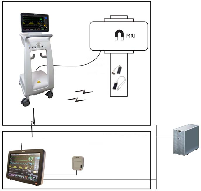
ExpressionMR400InstructionsforUseSystemOverview2‐3
Acquisition and Control
UseoftheMR400isrestrictedtoonepatientatatime.TheMR400displayspatient
measurementsacquiredduringmonitoring.Controlsandsettingsforpatientmonitoringare
providedlocallyonthetouchscreenorremotely(forexample,intheMRIcontrolroom)when
equippedwiththeIP5,whereconnectionsfortheprinterandthehospitalnetworkarealso
available.
Synchronization
TheMR400willautomaticallyestablishcommunicationwiththewirelessmodules,andIP5(if
equipped).However,duetotheusemodel,thedevicescanestablishcommunicationand
synchronizepower‐onsettingsaccordingtothestart‐upsequence:
•IftheMR400bootsandcommunicatesfirst,thenitssettingswillbereflectedattheIP5.
•IfanIP5bootsandcommunicatesfirst,thenitssettingswillbereflectedattheMR400.
IfusinganIP5,patientidentifiableinformation(nameandIDnumber)willbeavailableafter
synchronizationoccurs.
MR400
IP5
Hospital network
HIS system
MRI magnet room
MRI control room
Patient
table
MR400 to IP5 (wireless)
Modules to MR400
(wireless)
USB
Ethernet
Printer
Gating cable

2‐4SystemOverviewExpressionMR400InstructionsforUse
WARNINGS WARNINGS
•The use model specifies one IP5 per MR400 system. If more than one IP5 is present on
the MR400 system, there is an increased risk of units within the system not
synchronizing and displaying incorrect or corrupted settings.
• The MR400 should not be used adjacent to or stacked with other equipment. If
adjacent or stacked use is necessary, the equipment or system must be observed to
ensure normal operation in the configuration in which it will be used.
CAUTION
If the monitor’s settings are adjusted since they were last recalled or stored (manually, or via
synchronization if using an IP5), the User Settings key (see page 2-15) will be appended with a
plus symbol (+). The symbol will only be removed if the current settings are saved (see page 3-15)
or if different settings are recalled (see page 3-26). Always confirm the proper settings for the
MR400 and IP5 to ensure expected monitoring functionality.
Note
See Default Settings (on page 3-7) for information about the system’s power-on setup.
Device Control
Menucommandsthatcontrolparameterfunctionsforpatientmonitoringaresynchronized
betweentheMR400andIP5.Commandsthatdonotdirectlycontrolpatientparameters(for
example,printerfunctions)willonlyaffecttheIP5.Othercontrolsettingsremainlocalizedtothe
IP5andarenotsynchronizedwiththeMR400,includingthealarmaudiooffandalarmaudio
pausefunctions,andthevolumesettings;seetheIP5IFUforacompletelisting.
Note
If a systemic failure of the processing hardware, software or communications renders an intended
task incomplete and unperformed, a watchdog circuit will automatically shutdown power to the
WPU portion of the MR400. This will result in the removal of all patient data and displayed
information, and a continuous alarm will sound until power to the MR400 is turned off. If this
problem persists, contact technical support.
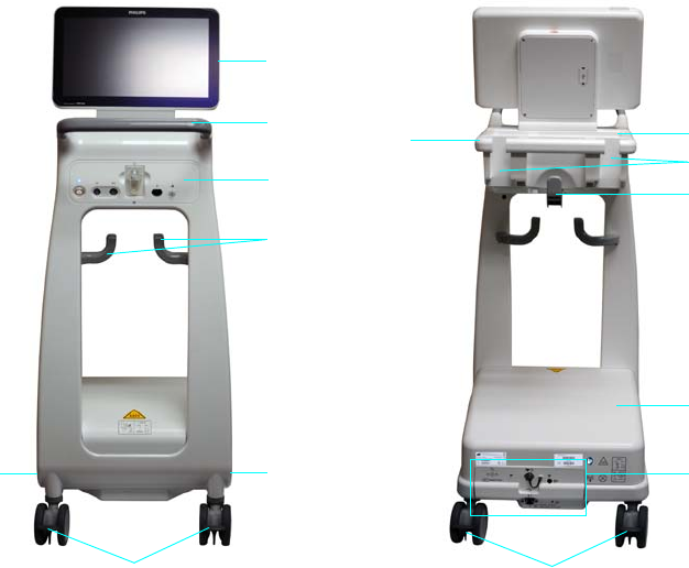
ExpressionMR400InstructionsforUseSystemOverview2‐5
Hardware Features
Cart
DesignedforuseintheMRmagnetroomandthroughouttheMRsuite,theMR400isaself‐
containedmobilepatientmonitoringsystem.TheMR400featuresawheeled‐cartdesignwith
fourlargelockablecastersunderitsaluminumframeandincludesintegratedsystemsfor
processing,power,displayandcontrol,asoutlinedbelow.
1Display panel (see page 2-6 for details).
2Guide handles provides the means for positioning the cart; see
page 3-2 for details.
3Patient connection panel (see page 2-7 for details).
4Accessory hooks provide storage for sampling lines, cables, et
cetera.
5Battery compartments house the main batteries; see page 1-16
details.
6Casters with wheel locks that, when engaged, prevent
movement of the cart.
1
2
3
4
5
5
9
66
7
8
4
10
2
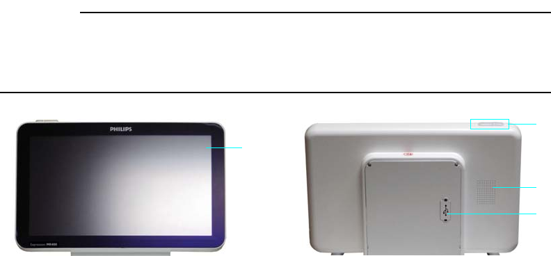
2‐6SystemOverviewExpressionMR400InstructionsforUse
Display Panel
ThedisplaypanelincludesatouchscreenLCD(liquidcrystaldisplay),thealarmindicatorsandan
audiospeaker.Thedisplaypanelcanbetiltedbackwardorforwardtoachievethebestviewing
angleandreduceanyglareonthetouchscreenproducedbyambientlighting.
CAUTION
Never use the display panel to position the MR400; severe damage or failure can result. Only use
the guide handle to position the MR400. If breakage of the display panel glass does occur and you
contact the liquid crystal by chance, please wash it from your skin using soap and water.
7Storage basket provides storage for Quadtrodes, cuffs, SPO2
attachments and other small accessories; see page 2-12 for
details.
8Module holders provide storage for the wECG and wSpO2
modules; see page 2-12 for details.
9Wireless processing unit (WPU) houses the communication,
processing and power systems for the MR400.
10 Rear panel houses connections for AC mains power, earth
ground, gating, USB port (service use only), (optional) waste gas
output, and (optional) O2 sensor.
1Touch screen provides displayed information and control of
the MR400, and can be used with gloved fingers.
2Alarm light provides a visual indication of an alarm condition.
3Speaker provides all audible indications.
4USB port provides service-related functions.
1
2
3
4
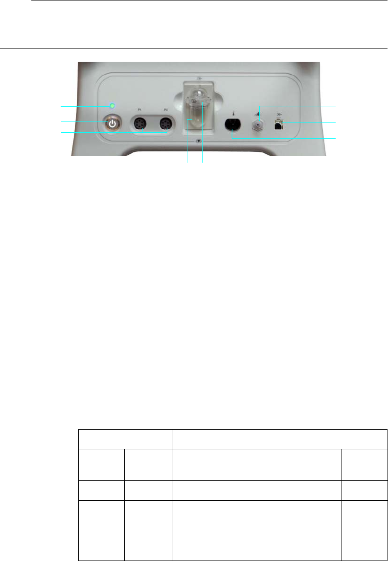
ExpressionMR400InstructionsforUseSystemOverview2‐7
Patient Connection Panel
ThepatientconnectionpanelcontainsthepowerswitchandLED,andinputconnectionsfor
variouspatientaccessories.
Note
The illustration shown below features a composite of all available options. Your MR400 will not
have all of these options.
1NIBP interconnect hose port
2(Optional) Loflo CO2 sampling line port
3(Optional) Temperature port
4(Optional) AGENT sample port
5(Optional) AGENT water trap
6(Optional) Invasive blood pressure ports (P1 and P2)
7Power switch (standby switch) is a push-type latching switch that
controls power (AC mains or batteries) to the MR400
8Power LED indicates the power source and power status of the
MR400, as detailed in the table below
Power LED Condition / Meaning
Color State Power Source Power
Switch
None Off None (batteries may be installed) Off
Green Steady Depending upon power source:
• If AC is present, then AC mains
• If AC is not present, then
batteries
On
8
7
4
3
2
1
6
5

2‐8SystemOverviewExpressionMR400InstructionsforUse
wECG and wSpO2 Modules
ThewECGandwSpO2modulesarebatterypoweredandcommunicatewiththeMR400through
abidirectional2.4GHzRFlink,whichisautomaticallyestablishedapproximately30secondsafter
powerisappliedtothemodule.Thesewirelessmodulesoperateatadistanceofupto9.1m(30
feet)fromtheMR400cartwhenalldevicesareplacedwithinthesameMRIroomorwithinthe
sameshieldedroom.
Thenetworkchannelandbatteryindicatorsdenotetheselectednetworkchannelandthe
batterystatusforeachwirelessmodule.Aftercommunicationshavebeenestablished,all
module‐dependentvitalsigninformationwillbedisplayedwithin10secondsontheMR400.
WARNING
The system use model specifies one wECG module and one wSpO2 module per MR400
system network channel. If more than one type of each module is communicating on the
same network channel, then waveform and measurement corruption will occur.
Red Steady Power fault detected; contact technical
support.
N/A
Blue Blinking Batteries are charging Off
Blue Steady Batteries at full charge Off
Power LED Condition / Meaning
Color State Power Source Power
Switch
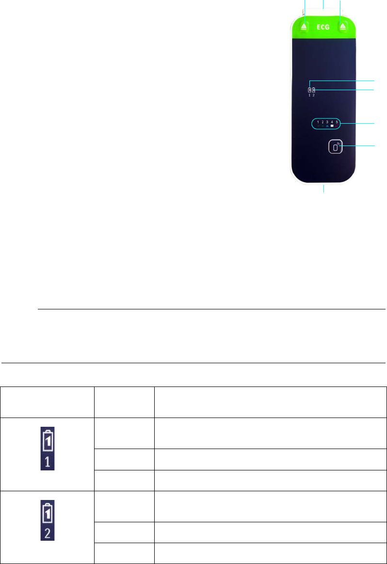
ExpressionMR400InstructionsforUseSystemOverview2‐9
wECG Module
ThewECGmoduletransmitsmeasuredECGsignalsthroughtheRF
linktotheMR400,wheretwoECGsignalscanbedisplayedandare
availableforinterfacingwiththeMRsystemcardiacgatinginput.
ThemodulealsoreceivesinformationfromtheMR400toperform
commandedtasks(forexample,leadviewandfiltermode
selections).
wECG Module Indicators
BatteryindicatorsprovidechargestatusindicationsforeachbatteryusedbythewECGmodule,
asdetailedinthetablebelow.
Notes
• A battery time-remaining counter is displayed by the MR400; see page 2-16 for details.
• For battery replacement details, see page 1-24.
1Battery 1 eject button
2Batteries
3Battery 2 eject button
4Battery 1 indicator
5Battery 2 indicator
6Network channel indicators (1–5, in this example)
7Network selection button
8ECG lead cable connector
4
1
5
6
7
8
23
wECG Battery
Indicator Color Charge Status
None Battery not installed in battery bay 1, or the battery’s
charge is insufficient to power the module
Green Battery installed in battery bay 1 has sufficient charge
Red Battery installed in battery bay 1 has low charge
None Battery not installed in battery bay 2, or the battery’s
charge is insufficient to power the module
Green Battery installed in battery bay 2 has sufficient charge
Red Battery installed in battery bay 2 has low charge
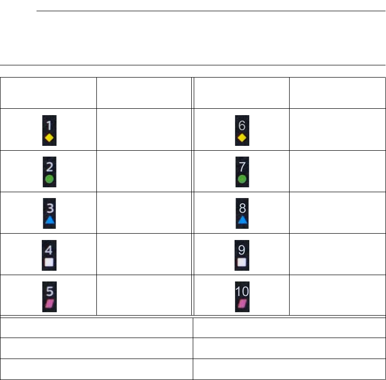
2‐10SystemOverviewExpressionMR400InstructionsforUse
Networkchannelindicatorilluminatestoprovidethewirelessnetworkchannelindicationand
thestatusofthewECGmoduletoMR400communications,asdetailedinthetablebelow.
Notes
• The communication status is also displayed by the MR400; see page 2-16 for details.
• For network channel selection details, see page 1-29.
Network Channel
Indicator Channel Selected Network Channel
Indicator Channel Selected
Channel 1
Channel 6
Channel 2
Channel 7
Channel 3
Channel 8
Channel 4
Channel 9
Channel 5
Channel 10
Network Channel Indicator State Communication Status
Steady Good communication
Flashing No communication
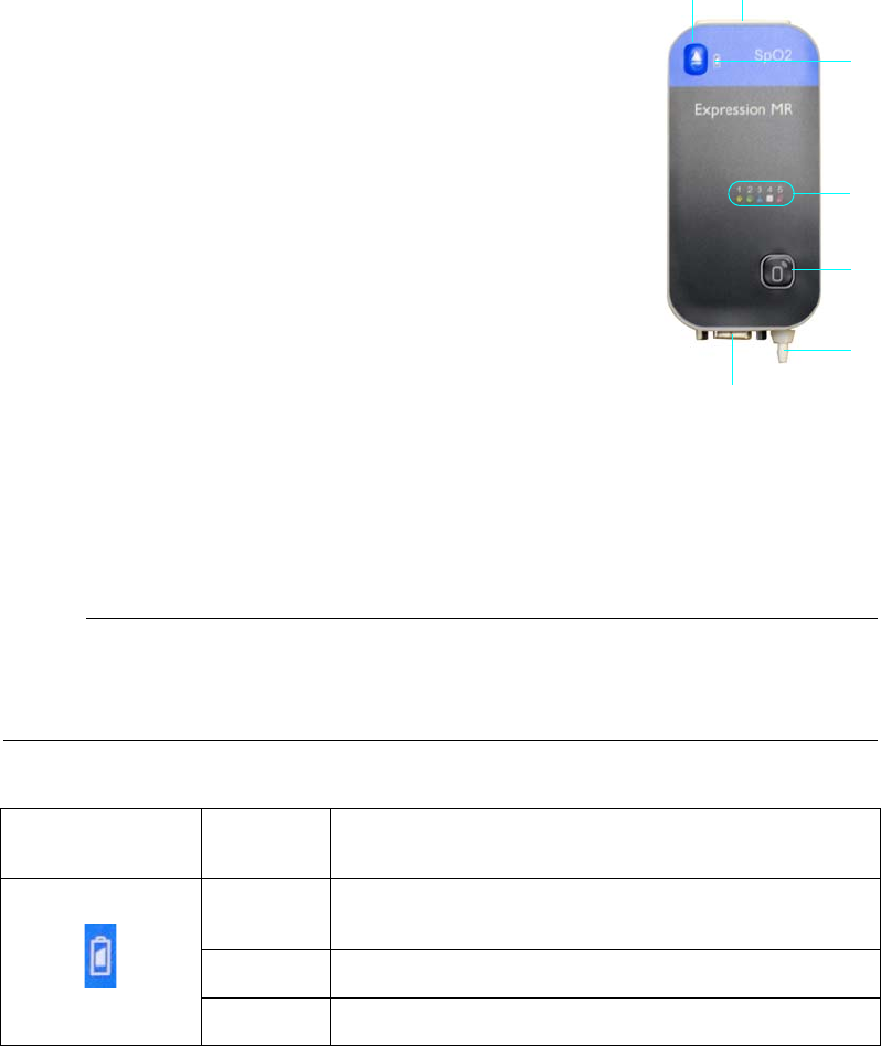
ExpressionMR400InstructionsforUseSystemOverview2‐11
wSpO2 Module
ThewSpO2moduletransmitsmeasuredbloodoxygensaturation,
plethysmography,peripheralpulsedataandpneumaticrespiration
ratevaluesthroughtheRFlinktotheMR400,wheretheprocessed
informationcanbedisplayedandoutputforinterfacingtotheMR
systempulseperipheralandrespirationgatinginput.
wSpO2 Module Indicators
BatteryindicatorprovideschargestatusindicationsforthewSpO2module,asdetailedinthe
tablebelow.
Notes
• A battery time-remaining counter is displayed by the MR400; see page 2-16 for details.
• For battery replacement details, see page 1-26.
Networkchannelindicatorilluminatestoprovidethewirelessnetworkchannelselection
indicationandthestatusofthewSpO2moduletoMR400communications,asdetailedinthe
tablebelow.
1Battery eject button
2Battery
3Battery indicator
4Network channel indicators (1–5, in this example)
5Network selection button
6Pneumatic respiration port; see page 10-2
7SPO2 probe connector; see page 1-18
3
1
5
4
7
6
2
wSpO2 Battery
Indicator Color Charge Status
None Battery not installed or its charge is insufficient to power
the module
Green Battery charge sufficient
Red Battery charge low
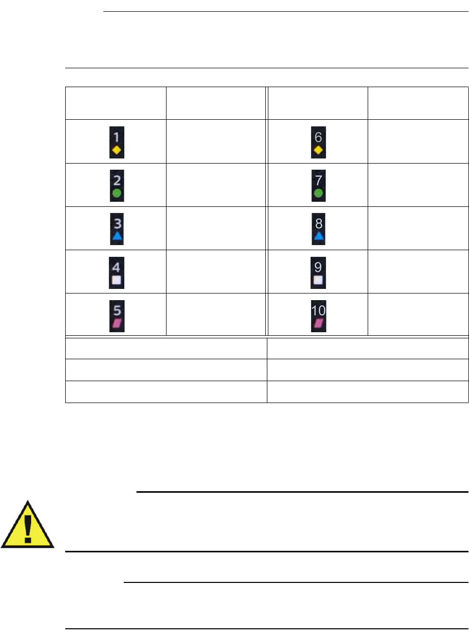
2‐12SystemOverviewExpressionMR400InstructionsforUse
Notes
• The communication status is also displayed by the MR400; see page 2-16 for details.
• For network channel selection details, see page 1-29.
Storing Modules and Accessories
WARNINGS WARNINGS
•Never store items containing ferrous materials on the cart or in the storage basket.
Failure to observe this warning may result in serious injury.
• To reduce the spread of infection, never store accessories on the cart guide handles.
CAUTION
When storing or removing the wECG and wSpO2 modules from the module holders, grasp only
the module and never pull or apply excessive force or tension to any connected attachment.
Network Channel
Indicator Channel Selected Network Channel
Indicator Channel Selected
Channel 1
Channel 6
Channel 2
Channel 7
Channel 3
Channel 8
Channel 4
Channel 9
Channel 5
Channel 10
Network Channel Indicator State Communication Status
Steady Good communication
Flashing No communication
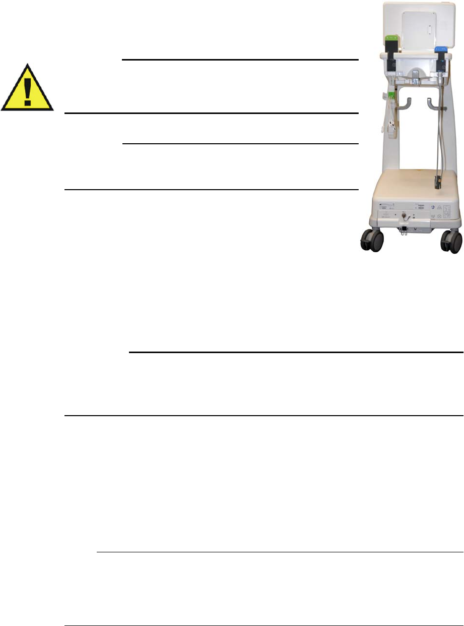
ExpressionMR400InstructionsforUseSystemOverview2‐13
TostorethewECGmoduleandaconnectedECGleadcable
LooptheECGcabletrunkwithfoaminsulatorandsecureitusingthe
Velcrostoragestrap(seepage5‐2).Then,placethewECGmodule
intoamoduleholderandallowtheECGleadcabletodrape.
WARNING
Do not use the Velcro storage strap to loop the ECG lead cable
during MR scanning; otherwise, there is a risk of cable heating
and possibly skin burns.
CAUTION
Failure to loop the Velcro storage strap on the ECG cable trunk may
result in damage to the lead cable due to contact with the floor.
TostorethewSpO2moduleandaconnectedprobe
PlacethewSpO2moduleintoamoduleholderandallowtheSPO2
probetodrape.
Tostoresmallaccessories,samplelinesandthetemperaturesensor
•Usetheremovablestoragebaskettoholdsmallaccessories(Quadtrodes,SPO2clipsand
grips,etcetera).Toremovethestoragebasketfromthecart,graspthebasketandlift.
•Usetheaccessoryhookstohangloopedsamplelines,thetemperaturesensor,etcetera.
CAUTIONS
• Do not place more than 2.2 kg (5 pounds) of combined weight of items in the storage
basket, module holders and accessory hooks.
• Never stack items onto or drape objects over the guide handle.
Displayed Information and Controls
ThedisplayedinformationandcontrolsfortheMR400aregroupedonthetouchscreen
accordingtofunction.
Note
The example below depicts information displayed by a fully-equipped MR400. Information
displayed by the MR400 will vary according to the equipped options and activated parameters. If
a parameter (or an ECG trace) has been turned off, its portion of the display will be blank. To
turn a parameter on or off, use Parameters in the Monitor Setup menu; see page 3-18 for details.
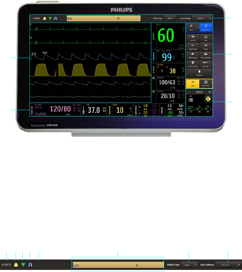
2‐14SystemOverviewExpressionMR400InstructionsforUse
Information Bar
Theinformationbarprovidesgeneraluse,vitalsigndetectionandpatientinformation.
1Information bar
2Soft keypad
3Status information pane
4Vital sign boxes
5Vital sign traces
4
3
2
1
5
1Set Time indication, and when pressed accesses the date; see
page 3-13.
2Alarm sound state indication; see page 4-4.
3Heart beat detection indication (and provides a detection tone)
according to the HR Tone Source setting; see page 3-21.
4Respiration detection indication when CO2-derived respiration is
on and within specified limits, flashing at a frequency that matches
the current breath rate.
1234 8
6 7
5
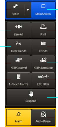
ExpressionMR400InstructionsforUseSystemOverview2‐15
Soft Keypad
Thesoftkeypadprovidesimmediateaccesstofrequentlyusedmenusandfunctions.
5Alarm Light setting indication; see 4-20.
6Patient information area, which displays the patient’s name and
identifier (ID) when available from an IP5.
7 Patient Type key and the current patient type setting indication;
and, when pressed, accesses the Patient Type menu (see page 3-
11).
8 User Settings key and user settings file name indication (where
the plus symbol [+] indicates that changes have occurred); and,
when pressed, allows you to select a factory or a stored user setup
(see Edit User Settings on page 3-15).
1 Main Screen key returns the MR400 to normal mode, closing any open menu,
option or dialog box
2Print key controls the remote print function and indicates the current state of
the printer
3 Trends key accesses the Tabular Trends menu
4 NIBP Start/Stop key starts or stops an NIBP measurement
5 ECG Filter key accesses the ECG Filter Mode options
1
2
3
4
5
6
7
8
9
10
11
12
13
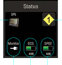
2‐16SystemOverviewExpressionMR400InstructionsforUse
Status Information Pane
ThestatusinformationpaneprovidesindicationsfortheMR400andwirelessdevices:
• Communicationandpowerindicationswillbedisplayedwithin2seconds.
6 Suspend key places the MR400 in suspend mode
7 Audio Pause key temporarily deactivates alarms
8Alarm key acknowledges an active alarm
91-Touch Alarms key sets all alarm limits according to preset calculation
values
10 NIBP Interval key accesses the automatic measurement Interval options
11 Clear Trends key clears stored trend data
12 Zero All key zeros all active invasive blood pressure channels
13 Setup key accesses the Monitor Setup, Printer, and Alarms menus
1Monitor network icon, which indicates the selected wireless
network channel (1, in this example) and, when pressed, allows you
to select the channel used by the MR400; see Setting the Wireless
Network Channel of the Cart on page 1-27 for details.
2Indicates the battery time-remaining (given in an hours:minutes
format) until power will be exhausted for the wSPO2 module; also,
indicates that the wSPO2 module’s communication with the
MR400 is good.
1
2
3
4
5
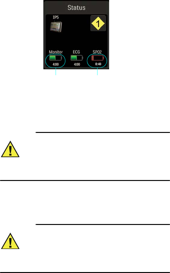
ExpressionMR400InstructionsforUseSystemOverview2‐17
•Powersourcechange‐of‐stateindicationsaredisplayed.
3Indicates the battery time-remaining (given in an hours:minutes
format) until power will be exhausted for the wECG module; also,
indicates that the wECG module’s communication with the MR400
is good. For detailed battery information regarding the wECG
module batteries, see Status Information Panel on page 2-18.
4Indicates the current power type used by the MR400 (AC power in
this example).
5Indicates that an IP5 is communicating with the MR400.
1Indicates a low battery condition and the approximate time (given
in an hours:minutes format) until power will be exhausted for a
module battery (wSpO2 in this example); also, indicates that the
module’s communication with the MR400 is good.
WARNING
A red battery symbol indicates that the module
batteries have fallen below the required operational
output and module shutdown with loss of monitoring
will occur. Immediately replace the module batteries to
avoid a loss in monitoring.
2Indicates that the cart batteries are the current power type used by
the MR400 and the approximate time (given in an hours:minutes
format) until power will be exhausted.
WARNING
A red battery symbol indicates that the main batteries
in the MR400 have fallen below the required
operational output and system shutdown with loss of
monitoring will occur. Immediately locate an AC outlet
and connect the MR400 to avoid a loss in monitoring.
1
2
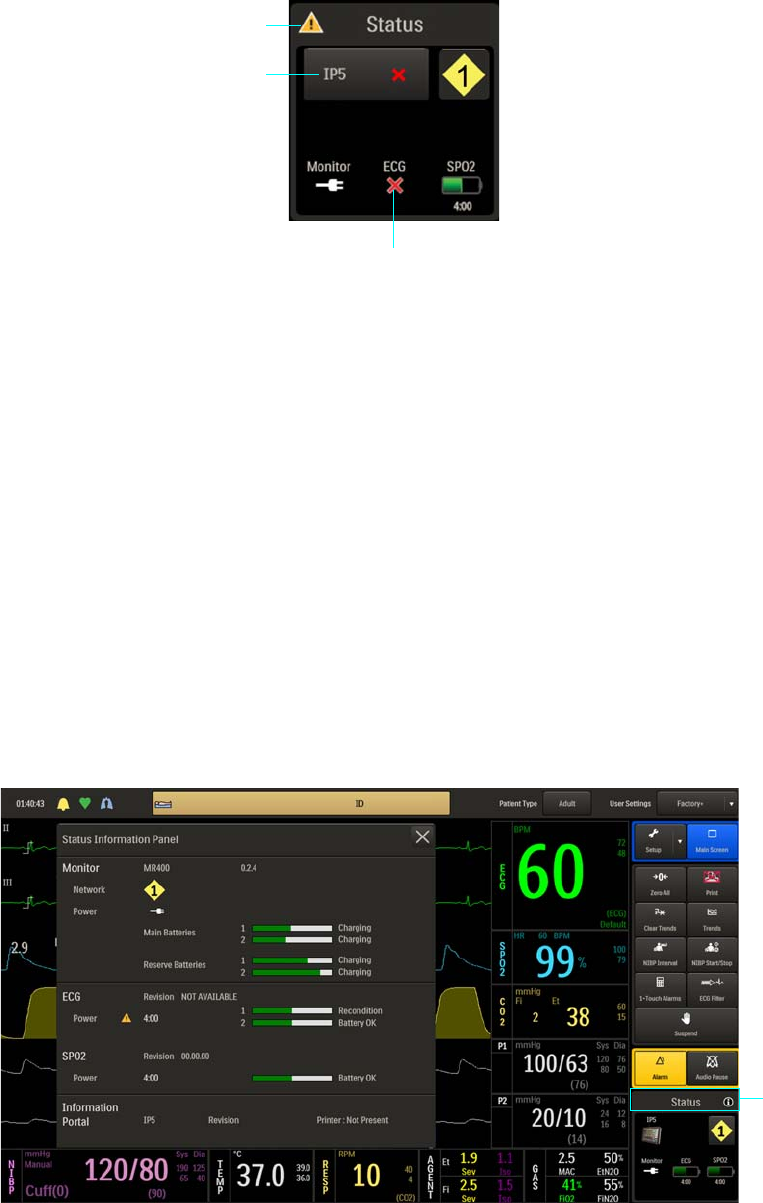
2‐18SystemOverviewExpressionMR400InstructionsforUse
• Indicationsareprovidedforalossofcommunication,whichisindicatedwithin2seconds,
andanodatacondition(seepage2‐20)willbedisplayedwithin10secondsforallvitalsign
informationmissingduetoanon‐communicatingwirelessmodule.
Status Information Panel
Thestatusinformationpanelprovideswirelesscommunicationandpowerdetails,includingthe
chargelevelofallconnectedbatteries.
Toopenthestatusinformationpanel
Selectthetitlearea(1,below)onthestatusinformationpane.
1Indicates that no communication is occurring between the MR400
and a wireless module (wECG in this example), or between the
MR400 and the IP5.
2Indicates a status warning when a communication error between
the MR400 and a wireless module, or between the MR400 and an
IP5 is detected.
1
2
1
1
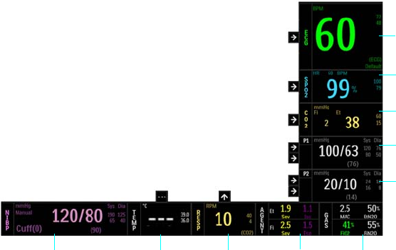
ExpressionMR400InstructionsforUseSystemOverview2‐19
Vital Sign Boxes
Vitalsign(VS)boxesareuniquelycoloredandlabeledgraphicframesthatcontainthenumeric
measurementsandcurrentalarmlimitssettingsforeachmonitoredparameter.Trending
indications(arrows)areavailableforeachmonitoredvitalsign,exceptNIBP.Inaddition,theVS
boxes(exceptAGENTandGAS)accesstheassociatedparameter’smenu.
1ECG VS box provides electrocardiogram and heart rate
measurements.
2SPO2
VS box provides blood oxygen saturation/pulse oximetry
and the heart rate measurements from pulse detection.
3CO2 VS box provides CO2 measurements and can also provide
respiration measurements.
4P1 VS box provides invasive blood pressure measurements for
channel 1 when equipped with the invasive blood pressure
option.
5P2 VS box provides invasive blood pressure measurements for
channel 2 when equipped with the invasive blood pressure
option.
6GAS VS box provides the total MAC value, O2 and N2O
measurements when equipped with the AGENT option.
7AGENT VS box provides anesthetic agent measurements
when equipped with the AGENT option.
8RESP VS box provides respiration rate measurements from
CO2 or the bellows accessory.
1
2
3
4
5
7
8
9
10 6
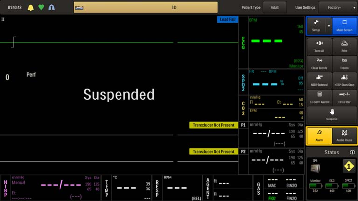
2‐20SystemOverviewExpressionMR400InstructionsforUse
No Data Indications
Undercertainconditions,nowaveformsandoneormorevitalsignnumericsmaydisplaythree
dashes(‐‐‐),whichindicatesthatnodataisavailablefortheparameter(s).
Dependinguponthecauseofthismissingdata,analarmconditionmaybegenerated.
Nodataindicationsthatmaynotgenerateanalarm
•Ifamoduleoranothermeasurementdevicewasjustturnedonorappliedtothepatient,
allowafewsecondsforcommunicationtobeestablished,orforanyrequiredwarm‐up
periodtooccur.
•Thefirstreadinghasnotyetbeentakenortheparameterisinastart‐upcondition(for
example,theAGENTorCO2monitoringhardwaremaybewarmingup).
•Themeasurementvaluesaredistortedorthesignalisinadequate(forexample,the
concentrationofgasesmaybebelowtheminimumvolumepercentagedetectable).
• Suspendmodewasjustexited.
Nodataindicationsthatmaygenerateanalarm
• Parameterdatawaspresentbutcannolongerbeproduced(forexample,anattachment
appliedtoapatientmayhavebecomedisconnected).
•Thehardwareassociatedwithaparameterhasexperiencedaproblemorfailurethat
preventsproperoperation.
9TEMP VS box provides temperature measurements when
equipped with the temperature option.
10 NIBP VS box provides non-invasive blood pressure
measurements.
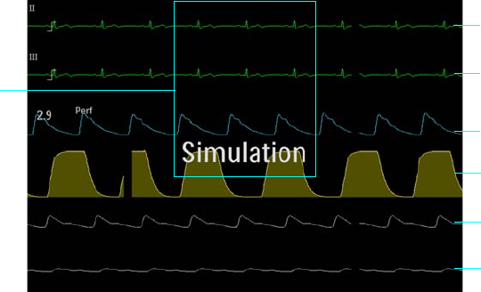
ExpressionMR400InstructionsforUseSystemOverview2‐21
Other Data Indications
TheOverStateIndication(OVR)
Ifthevalueofthenumericdataiteminthevitalsignboxisgreaterthanthehighestvalue
specifiedfortheitem,OVRwillbedisplayedinanalarmconditioninplaceofthenumeric.Seethe
tableonpage4‐25formeasurementrangeanddeclarationinformation.
TheUnderStateIndication(UND)
Ifthevalueofthenumericdataiteminthevitalsignboxislessthanthelowestvaluespecifiedfor
theitem,UNDwillbedisplayedinplaceofthenumericinanalarmcondition.Seethetableon
page4‐25formeasurementrangeanddeclarationinformation.
Vital Sign Traces and System Message Area
Vitalsign(VS)tracesareuniquelycoloredwaveformsfortheECG,SPO2,CO2andinvasiveblood
pressureparameters.Thesetracesarefixedacrossthescreen,adjustableandupdatedfromleft
torightwithanerasebar.ThewaveformcolorcorrespondstothecoloroftheassociatedVSbox
numericdataforthatparameter.Uptosixwaveformscanbedisplayed,butifaparameteris
turnedoffthenthattraceportionofthescreenandVSboxwillbeblank.
Systemmessagesandsomealarmflags,asdetailedthroughoutthismanual,aredisplayedinthe
centerandtopportionsofthevitalsigntracesarea.Multiplesystemmessagesoralarmflagswill
bestackedinthisarea.
1Trace A displayed as the ECG 1 waveform depending upon the
selected source
2Trace B displayed as the ECG 2 waveform when two ECG
sources are selected
3Trace C displays the SpO2 waveform
1
2
3
4
5
6
7
2‐22SystemOverviewExpressionMR400InstructionsforUse
Navigation and Operation
EverythingneededtonavigateandoperatetheMR400canbeperformedbyselectinganactive
elementonthetouchscreen(includingsoftkeysandbuttons,icons,menus,VSboxesandalarm
limitssettings).Whenanactiveelementistouchedwithafingerorapassiveobject(suchasa
stylus),theMR400willhighlightthatoptionoritem,produceatoneandenacttheselection.
CAUTION
Never apply unnecessary pressure or use sharp objects on the touch screen as damage or failure
can result. If breakage of the display panel glass does occur and you contact the liquid crystal by
chance, please wash it from your skin using soap and water.
Notes
• Simultaneously touching two or more screen areas may produce unpredictable results and
is not recommended.
• The design of the MR400 allows access to the same menus in different ways.
• The MR400 monitors all application processes. If a software process or an application
monitoring failure is detected, then an audible alarm will sound and all visual information
will be removed from the display. To restore normal operation, you must turn the power
switch off and then on. If the problem persists, contact technical support.
Specialized Control Buttons and Keys
Inadditiontothecontrolmethodsdescribedabove,somemenus,optionsanditemsinclude
specializedsoftkeysandbuttonsthatcontrolmenus,settingsandentries:
•Todecrementanumericvalue,select.
•Toincrementanumericvalue,select.
4Trace D displays the CO2 respiration waveform (breath rate)
5Trace E displays invasive blood pressure, channel 1 (P1)
waveform
6Trace F displays invasive blood pressure, channel 2 (P2)
waveform
7 System message area displays system messages and alarm flags;
see chapter 4.
ExpressionMR400InstructionsforUseSystemOverview2‐23
•Tocloseamenuoritem,select.
•Toclearanentryfield,select.
•Tosaveentereddataandcloseamenuoritem,select.
•Toenterdata,savechangesandcloseamenuoritem,select.
Default Setting Indications
Thedefaultsettingofamenuappearsasthehighlighteditem,orastheitemwithanasteriskina
menu.
System Messages
Systemmessagesaredisplayedtoinformyouaboutacurrentoperationorcondition,as
discussedthroughoutthismanual.AlsoseeSystemStatusIndicationsonpage4‐31.
Password Protection
Entryofasix‐digitpasswordisrequiredforaccesstosome
menus,especiallyservice‐relatedmenus.(Contacttechnical
supportforinformation.)
WhenEnterPassword:isdisplayed,usethekeypadtoenterthe
correctpasswordtocontinuetothedesiredmenu.
Modes of Operation
TheMR400hasthreeoperatingmodes:normal,suspend,andsimulation.
Normal Mode
Normalmodeisthestandardoperatingmode.Innormalmodetherearenoopenmenusor
highlightedvitalsignboxes;thesystemisreadyformonitoring.

2‐24SystemOverviewExpressionMR400InstructionsforUse
Toenternormalmode
PresstheMainScreenkey.
AnyopenmenuwillcloseandanyhighlightedVSboxwillbedeselected(thatis,thenormalscreen
willbedisplayed).Seepage2‐14foranillustration.
Suspend Mode
WARNING
Suspend mode should never be used to silence alarms or when a patient is being actively
monitored as a delay in treatment and possible patient injury could result.
Suspendmodesupportspatient‐clinicianinteractionwithoutnuisancealarms,whichisuseful
whereminimaluserinteractionisrequired(forexample,whileapatientisnotbeingmonitored,
duringtransitionswhenremovingthemonitorfromonepatientandconnectingitonanother,or
ifcertainadjustmentsarebeingmadetothedeviceorotherequipment).
Insuspendmode,currentpatientinformationisprovided,butwiththefollowingoperational
exceptions:
•Audiblealarmsaredisabled;
•ActiveautomaticNIBPmeasurementsaresuspended;
•DefaultinflationpressuresareusedforallmanualNIBPreadings;and,
•IfequippedwithanIP5andprinter,automaticprintoutswillnotbegenerated.
Toentersuspendmode
PresstheSuspendkey.
Suspendedwillbedisplayedatthecenterofthescreen.Seepage2‐20foranillustration.
Toexitsuspendmode
PresstheSuspendkey.
Simulation Mode
Simulationmode,apasswordprotectedfunction,supportstrainingandtestingneedsby
displayinginternally‐generateddataforvitalsignwaveforms,numericvaluesandstatuses.In
simulationmode,allpatientmonitoringisdiscontinued.Seepage3‐29formenudetails.
ExpressionMR400InstructionsforUseGettingStarted3‐1
CHAPTER 3
Getting Started
Initialsetupisimportanttoachieveexpectedresultsandseamlessoperation.
WARNINGS
•Perform operational verification prior to use. If the MR400 fails to function properly,
remove it from use and contact technical support personnel.
• Do not allow the patient to move while the MR400 is being used as over-activity may
result in prolonged or inaccurate readings.
• Position of the accessories may affect measurement accuracy. Always consult a
physician for interpretation of measurements provided by the MR400.
• Do not operate the MR400 outside the specifications indicated in Appendix A as it will
cause inaccurate results.
CAUTIONS
• A minor but noticeable degradation in wireless module communications may occur in the
presence of high-powered radios.
• Prior to clinical use, the user must be aware of the minimum distance from the MR magnet
that must be maintained for proper operation; see Positioning the MR400 on page 3-2 for
details.
Defibrillator and Electrosurgical Use
TheMR400hasadefibrillation‐proofdegreeofprotectionthatallowsapatienttobedefibrillated
whileconnectedtothewECGmoduleandleads.Whenusingadefibrillator,followallprecautions
relatedtoboththeMR400andthedefibrillatorequipment.Duringadefibrillationprocedure,the
ECGwaveformwillsaturatethenrecoverinlessthan5secondsinaccordancewithAAMI/ANSI
EC13andIEC60601‐2‐27.
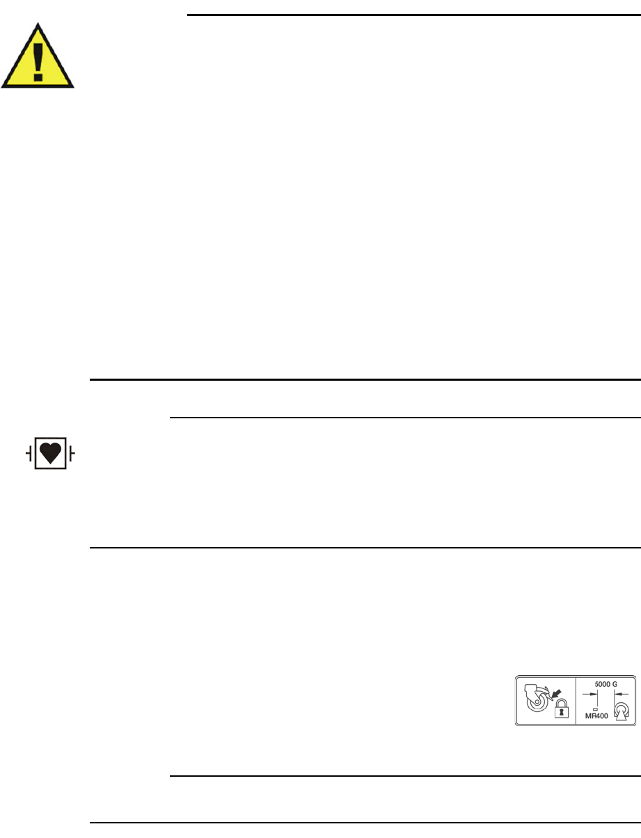
3‐2GettingStartedExpressionMR400InstructionsforUse
WARNINGS
•The patient connector inputs for all parameters are protected against the use of a
defibrillator by internal circuitry when the recommended patient cables or accessories
are used.
• Defibrillation and electrosurgery: Do not touch the patient, or table, or instruments,
during defibrillation. This equipment does not provide protection against burning of
the patient.
• The MR400 can be used in the presence of defibrillators or electrosurgery units,
provided the equipment being used is in good working order, meets appropriate safety
standards, is properly grounded and is operated correctly in the appropriate manner
and environment. Improperly grounded equipment can be a safety hazard and can
also cause interference to the ECG signal and result in a noisy ECG signal waveform
and inaccurate heart rate measurements.
• Electrosurgical unit overloads may cause damage to this device.
• To minimize risk of damage to the MR400 during defibrillation, use only the
manufacturer’s specified accessories and supplies.
• This equipment does not meet electrosurgical interference suppression (ESIS)
requirements as stated in EC13, sub clause 4.2.9.14, as the ECG trace will temporarily
disappear from the display during cut or coagulation bursts.
CAUTION
When using a defibrillator, do not introduce discharges of 360 joules or more, repeated five times
over 5 minutes. Read the safety instructions provided with the defibrillator. The MR400 cart is
designed to withstand defibrillation and will recover within 5 seconds (per IEC 60601-1,
Requirements for the Safety of Medical Electrical Equipment, and IEC 60601-2-49, Particular
requirements for the basic safety and essential performance of multifunction patient monitoring
equipment).
Positioning the MR400
Duringuse,stationthecartatasafemonitoringdistanceintheMR
magnetroomthenpressdownoneachwheellocktoengageit.(When
thecartneedstobemoved,raiseeachwheellockbeforeproceeding).
UsetheguidehandletomoveandpositiontheMR400.Alwaysplacethe
MR400sothatyourviewofthescreenandalarmlightwillremainunobstructedduringuse.
CAUTION
Never lean against or apply excessive force to the guide handle.
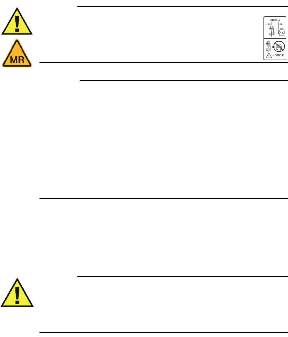
ExpressionMR400InstructionsforUseGettingStarted3‐3
WhenpositioningtheMR400foruse,observethefollowingwarningandcautions:
Warning
WARNING
.The MR400 shall meet its full function and performance specifications when
positioned in the MR room of a 3T magnet, up to the 5000 gauss line, 4W/kg
SAR, and 7.2 µT B1rms in all orientations. Always secure the MR400’s wheel
locks when the unit is placed within the MR system room. Failure to properly
position the MR400 and its accessories in the MR system room will result in
system or accessory failure, and possible patient or user injury.
CAUTIONS
• If the MR400 rolls to the face of the MR system due to magnetically induced pull force, do
not attempt to dislodge the MR400 by pulling from the display panel or guide handle;
instead, dislodge the MR400 by gently pulling from the lowest point of the base. This will
prevent the base of the unit from experiencing higher MR pull forces in the vertical
direction.
• Position the MR400 in a manner which does not block access to the device or wall plug
connectors.
• Field strength variations in a particular MR system room (which may be due to active
shielding technology, manufacturer variability, future enhancements, etc.) can make
distinguishing the 5,000 gauss level (as measured from the center line of the MR bore)
difficult. These variations may require moving the MR400 away from the MR system if
system abnormalities or malfunctions are observed. Prior to clinical use, ensure that the
allowable distance of the MR400 from the MR system is maintained for proper operation.
Operating the MR400
SAFETYAWARENESS
Warning
WARNING
Do not start up the product unless you and all other users present have read, fully
understood and know all the safety information and emergency procedures given in the
Safety section of this Instructions for Use. Operation of the product without having read,
understood and knowing ALL the safety information and procedures in the SAFETY section
could lead to fatal or other serious personal injury. It could also lead to clinical mis-diagnosis
or clinical mistreatment.
3‐4GettingStartedExpressionMR400InstructionsforUse
FollowthestepsbelowwhenoperatingtheMR400.
System Power-up and Communications Verification
Warning
WARNING
Always perform operational verification prior to use and during monitoring by ensuring
proper communications between the MR400, the wireless modules and IP5 (if equipped).
Failure to ensure proper communications can result in the loss of patient monitoring and the
loss of data transfer in networked systems equipped with an IP5. If a device fails to function
properly, remove it from use and contact technical support.
TheMR400reachesanoperationalstatewithin60secondsafterpower‐upandattainsfull
measurementaccuracyaccordingtotheequippedoptions:
• Afterapproximately2minuteswhenequippedwiththeCO2LoFlooption
• Afterapproximately10minutesifequippedwiththeAGENToption.
Whenanydisplayedwarm‐upmessagedisappears,theMR400isreadyforuse.
ToapplypowertotheMR400andverifysystemcommunications
Step Action
1Pressthepowerswitch;seepage2‐7forthelocation.
2EnsurethatthewECGandwSpO2modules(andIP5,ifequipped)
haveestablishedgoodcommunications,andthatsufficientpower
existsfortheMR400andthewirelessmodules.Alsoverifyproper
operationofthepatientparameters.
SeeSystemPower‐upandCommunicationsVerification,below.
Step Action
1EnsurethatbatteriesareinstalledinthewECGmodule(seepage1‐
24).
2CheckthebatteryindicatorsonthewECGmoduletoensurethat
enoughchargeexistsinatleastoneoftheinstalledbatteries:
• Greenbatteryindicator=Chargesufficient;proceedtostep4.
•Redbatteryindicator=Chargelow;proceedtostep3.
Seepage2‐9fordetails.(Also,youcanreferencethestatus
informationpane;seepage2‐16.)
3 Accordingtotheredbatteryindicator(s)presentonthewECG
module,insertachargedmodulebatteryintothecorresponding
batterybay(s)andthenrecheckthebatteryindicator(s)toensurea
sufficientchargebeforeproceeding;seepage1‐24.

ExpressionMR400InstructionsforUseGettingStarted3‐5
4EnsurethatbatteriesareinstalledinthewSpO2module(seepage
1‐26).
5CheckthebatteryindicatoronthewSpO2moduletoensurethat
enoughchargeexists:
• Greenbatteryindicator=Chargesufficient;proceedtostep7.
•Redbatteryindicator=Chargelow;proceedtostep6.
Seepage2‐11fordetails.(Also,youcanreferencethestatus
informationpane;seepage2‐16.)
6InsertachargedmodulebatteryintothewSpO2moduleandthen
recheckthebatteryindicatortoensureasufficientchargebefore
proceeding;seepage1‐26.
7WiththecartbatteriesinstalledandwiththeMR400connectedto
ACmainspower(seepage1‐20),pressthepowerswitch.Allowthe
MR400toinitialize.
8(Optional)Ifequipped,turnontheIP5.
9CheckthenetworkchannelindicatoronthewECGmoduleto
ensurecommunicationisestablishedwiththeMR400:
• Steady=Goodcommunication;proceedtostep11.
• Flashing=Nocommunication;proceedtostep10.
Seepage2‐9fordetails.(Also,youcanreferencethestatus
informationpane;seepage2‐16.)AninoperativeECGparameteror
wECGmoduleisindicatedbyabsenceofanECGwaveformanda
simultaneousLeadFailalarm.
10 EnsurethatthewECGmoduleiswithin9.1m(30feet)ofthe
MR400,inthesameMRIroomorinthesameshieldedroom,andis
settothesamewirelessnetworkchannelusedbytheMR400;see
page1‐29.
11 CheckthenetworkchannelindicatoronthewSpO2moduleto
ensurecommunicationisestablishedwiththeMR400:
• Steady=Goodcommunication;proceedtostep13.
• Flashing=Nocommunication;proceedtostep12.
Seepage2‐11fordetails.(Also,youcanreferencethestatus
informationpane;seepage2‐16.)
12 EnsurethatthewSpO2moduleiswithin9.1m(30feet)ofthe
MR400,inthesameMRIroomorinthesameshieldedroom,andis
settothesamewirelessnetworkchannelusedbytheMR400;see
page1‐29.
13 (Optional)IfequippedwithanIP5,ensurethatthewireless
networkchanneloftheIP5isthesameasthewirelessnetwork
channelsettingoftheMR400;seetheIP5IFUfordetails.
Step Action

3‐6GettingStartedExpressionMR400InstructionsforUse
CAUTION
If power to the wireless device with established communications is lost or removed, its network
connection will be dropped.
Cart Power-down
ToturnpowerofftotheMR400,pressthenholdthepowerswitchforapproximately2seconds.
NOTE
For instructions on the complete removal of power to the MR400, see page 14-2.
Wireless Module Power-down
Toturnpowerofftoawirelessmodule,removethebattery(wSpO2module)orbatteries(wECG
module).
Monitor Initialization
Afterpower‐upanduntiltheinitializationprocesscompletes,thetouchscreenmayremain
blank.Afterinitializationcompletes,theMR400canbeginmonitoringfunctionsfromaninitial
factorydefaultstateorfromapre‐configuredstate,dependinguponthewaythestored
configurationsandpatientdataareprogrammedforstartup.
Visuallycheckingthepatientandconfirmingchangingmeasurementsagainstothervitalsigns
shouldbestandardroutinesduringuse.
14 (Optional)IfequippedwithanIP5,ensuregoodcommunication
betweentheMR400andtheIP5bycheckingthestatusinformation
pane(seepage2‐16).
15 Ensureproperoperationofeachpatientparameterandalarms.
Refertoappropriatechaptersinthismanual.
Step Action

ExpressionMR400InstructionsforUseGettingStarted3‐7
Warning
WARNING
When using an IP5, make sure that the content of the User Settings option matches that of
the MR400 option, and that the same option is selected as the default setup on both systems
(see page 3-26). This is important because the device first booted will determine the power-
on settings of the system (that is, the MR400 and optional IP5).
Viewing the Displayed Information
ThehighresolutiontouchscreenLCDfacilitateswaveformanalysisandvitalsignnumeric
interpretation,withimportantdisplayelementswhicharedesignedtobelegibleataminimum
distanceof1meterbyuserswithavisualacuityof20/20.WhenusingtheMR400,alwaysadjust
theviewingangleofthetouchscreentocomplementyourlineofsightandalwaysensurethat
yourviewremainsunobstructed.
CAUTION
Never apply unnecessary force to the touch screen as it can result in damage or failure.
NOTE
To change the language displayed by the MR400, see System Config page 3-30.
Default Settings
Atpowerup,theMR400willautomaticallysetallmonitorsetupoptionsasdeterminedbythe
defaultselectionintheEditUserSettingsmenu.Bydefault,thefactorysettingsareusedwhen
thesystemisturnedon,unlessacustomsettinghasbeenselected.Also,asdiscussedearlier,due
totheusemodel,thepower‐ondefaultsettingsfortheMR400candependupona
communicatingIP5andthestart‐upsequenceofthedevices.
Default Setting Indications
TheUserSettingskeyindicatesthecurrentdefaultsetup(wheretheplussymbol[+]indicates
thatchangeshaveoccurred)anditallowsyoutoselectafactoryorastoredusersetup;seepage
2‐14.
Whenamenuisdisplayed,thedefaultwillbehighlightedorwillappearwithanasterisk.Forthe
factorydefaultsettings,seethemenulistingsthroughoutthisIFU.
3‐8GettingStartedExpressionMR400InstructionsforUse
User Settings
IntheEditUserSettingsmenu,uptotencustomizedusersettingscanbesavedandonecanbe
selectedforuseasthedefaultatpower‐on.Usersettingscanincludeanyofthefollowingmenu
options:
•Alarms
–Minimumandmaximumvalues
–Auto‐setpercentage
–Alarmsoundlevel
– ExtremeHRalarmvalues
–Desat
alarmvalues
• SystemSetups
•ECG
– Selectedlead
–Scalesetting
–Tracespeed
– Filtermode
–QRStoneon/off
–Heartratesource
– PediatricECGon/off
– ExtremeHRalarmfunctionsetting
•SpO2
–Size
–Desatalarmfunctionsettings
•CO2
–Size
–Grids
•CO2(RESP)
–Apneaalarmfunctionsettings
•NIBP
–Manual
–OfforAuto
–Automatictimeinterval
•Trendgraphs
–Timebases
–Scales
•PrintSetups
–OfforAuto
–Tracedelay
– Printerspeed
– Selectedtraces
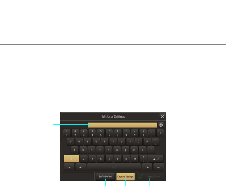
ExpressionMR400InstructionsforUseGettingStarted3‐9
NOTE
When a setting is changed in an active user settings file, a plus sign (+) will appear on the User
Settings key. And when edits have been made to an existing user settings file, a warning box and
setting change list will appear, prompting you to accept or cancel the changes to proceed.
SoftKeyboard—AddNew
Namescanbeassignedtoyourusersettingsfilesusingthesoftkeyboardthatisdisplayedwhen
theAddNewoptionisselected;seepage3‐15.Thissoftkeyboard(seeillustrationbelow)
functionslikestandardQWERTYkeyboard,butwithadditionalfeaturesfordatacapturesand
defaultsettingselection.
SoftKeyboard—EditExisting
Existingusersettingsfilescanbeeditedusingthesoftkeyboardthatisdisplayedwhenastored
fileisselected;seepage3‐15.Thefilenameanddatacontentscanbechanged,andthedefault
settingcanbeupdated.Theillustrationbelowhighlightstheseadditionalfilemanagement
featuresofthesoftkeyboard.
1Save & Close button assigns the captured settings to the
entered file name then saves the file in memory and closes the
menu.
2 Capture Settings button saves the current settings data of the
MR400.
3 Set To Default button selects the settings of the current entry
for use following power-up of the MR400.
4Entry field displays the currently entered file name for the
captured user settings.
1
2
3
4
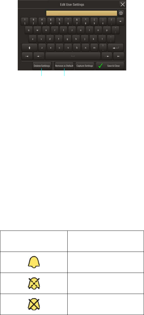
3‐10GettingStartedExpressionMR400InstructionsforUse
Initial Alarm Indications
Afterpower‐upandimmediatelyfollowingtherecallofastoredsetup,theMR400providesan
indicationofthealarmvolumebysoundingthealarmtoneatitscurrentlyadjustedsettingfor5
secondsanddisplayingCheckAlarmVolume.
Afterpower‐up,theinitialalarmstateispausedandthen,followingawaitperiodof120seconds,
armedbecomesthenormalalarmstate(asindicatedbythedisplayedsymbol,showninthetable
below):
Inthearmedstate:
•Analarmwillsoundwhileanalarmconditionexists,providedthatanypre‐alarmwait
periodhasexpiredandthealarmaudioarmedsymbolisdisplayed.
1 Remove as Default button removes the file as the default user
settings file
2 Delete Settings button deletes the file.
21
Displayed Symbol Alarm Sound State
Alarm audio armed
Alarm audio paused
Alarm audio off

ExpressionMR400InstructionsforUseGettingStarted3‐11
•Alarmflagsrelatedtootheralarmsoundstateswillberemovedfromthedisplay.
•Analarmconditionnotpreviouslyplacedinanaudiooffstatewillcausethealarmto
sound.
Selecting the Patient Type
DeterminingthePatientType
IEC80601‐2‐30Edition1.0,theinternationalstandardregardingparticularrequirementsfor
safety,includingessentialperformanceofautomaticcyclingnon‐invasivebloodpressure
monitoringequipment,definespatienttypesintwocategories:neonatalandadult.Neonatal
patientsaredefinedbytheapproximateagerangeofbirthtoafewweeks.Allotherpatientsare
identifiedasadults.
ANSI/AAMISP10:2008,theAmericanNationalStandardformanual,electronic,orautomated
sphygmomanometers,definespatienttypesaccordingtoagelimitations,asindicatedinthetable
below.
Similarly,theFood&DrugAdministrationdefinespatientswithintwocategories:pediatricsand
adults.Eachcategoryisfurtherdefinedintosubgroupsaccordingtoapproximateage.
CAUTION
There may be occasions when a particular mode is not suitable for its apparent category of patients
based on age alone. In these cases, a clinical decision shall be made to use another patient type or
measurement technique. The clinical decision shall be based on all of the factors listed in
Determining the Patient Type (above) to ensure the best possible and most timely measurement
acquisitions.
Patient Type Age
Neonatal Birth to 28 days
Pediatric 29 days to 12 years
Adult Greater than 12 years
Patient Type Subgroup Approximate Age Range
Pediatric Newborn (neonate) Birth to 1 month
Pediatric Infant Greater than 1 month to 2 years
Pediatric Child Greater than 2 to 12 years
Pediatric Adolescent Greater than 12 to 21 years
Adult --- Greater than 21 years
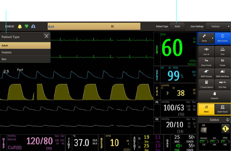
3‐12GettingStartedExpressionMR400InstructionsforUse
Regardlessofthedefinition,eachagencyrecognizesthatthepatienttypedescriptionscanbe
arbitraryandthatthefollowingpatientfactorsaremoreaccurateindeterminingtheappropriate
methodofpatientmonitoringandtreatment:
–Weight
–Bodysize
–Limbcircumference
– Physiologicaldevelopment
–Neurologicaldevelopment
– Neuromuscularcoordination
Accordingly,theMR400usesseveraloperationalparameters,includingcuffinflationpressure
andpulsesensitivity,thatvarydependingontheselectedpatienttype.(Alwaysreferto
informationaboutthecorrespondingparameterforotherpossibleconsiderationswhen
determiningthepatienttype.)
ThePatientTypekeyallowsyoutosettheMR400forthetypeofpatienttobemonitored.
ToopenthePatientTypemenu
PressthePatientTypekey.
Thefollowingpatienttypesareavailable:
•Adult(Default)
• Pediatric
Patient Type key
Patient Type menu
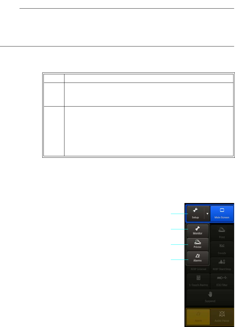
ExpressionMR400InstructionsforUseGettingStarted3‐13
•Neo(whenselected,PediatricECGwillalsobesettoOn)
NOTE
Changing the Patient Type causes the alarm to sound, Change NIBP Cuff to be displayed for 30
seconds, the initial cuff inflation to be reset to the initial pressure for the patient type selected,
NIBP > Auto Mode to be set to off, and the alarm limit settings to revert to the default values24).
Toselectthepatienttype
Setup Menus
PressingtheSetupkeywilldisplaytheMonitor,Printer,and
Alarmskeys.
TheMonitor,Printer,andAlarmskeysopenassociated
menusforsetupandcontrol,including:
•Savingandrecallingsetupconfigurations
• Controllingparameters
• Adjustingsounds
• Switchingpatienttypes
• Settingtimeanddate
Step Action
1PressthePatientTypekey.(Thecurrentsettingisdisplayed.)
ThePatientTypemenuappears.Thecurrentsettingishighlighted.
2 SelectthePatientType:
Adult
Pediatric
Neo
Thesettingisentered.
1 Setup key
2 Monitor key
3Printer key
4Alarms key
1
2
3
4
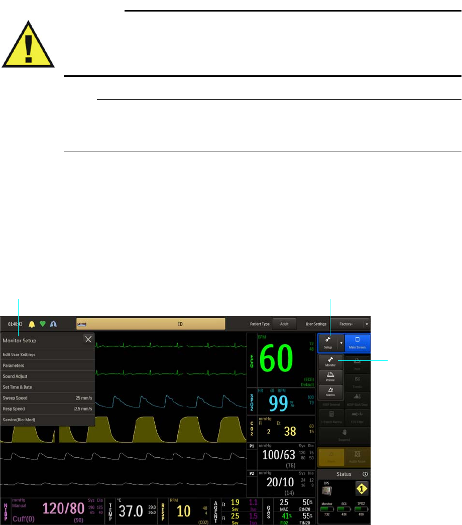
3‐14GettingStartedExpressionMR400InstructionsforUse
• Settingsweepspeeds
• ControllingECGmodes
• Controllingalarms
• Controllingremoteprinting
Warning
WARNING
When using an IP5, wait at least 4 seconds if performing a recall or setting a parameter
value, as these require a few seconds to propagate through the system. Performing another
recall within 4 seconds of a previous recall or after a value change, may result in improperly
recalled data.
NOTE
Grayed out items in the menu system, indicate features or options that are inaccessible due to
current settings, or that are not configured or installed.
Monitor Setup Menu
TheMonitorSetupmenuallowsyoutoconfiguretheMR400forpatientmonitoring.
ToopentheMonitorSetupmenu
PresstheSetupkeyandthentheMonitorkey.
Setup key
Monitor Setup menu
Monitor key

ExpressionMR400InstructionsforUseGettingStarted3‐15
ThefollowingMonitorSetupmenuitemsareavailable:
TochangesettingsintheMonitorSetupmenu
Edit User Settings
Allowsyoutocapture,storeandmanagemultipleusersetups,andtoselectanoperationalor
power‐updefaultsetup.Abackupandrestoreselectionalsoallowsyoutosavetheseuser
settingstoanexternaldevice.
ToopentheEditUserSettingsmenu
•Edit User Settings
• Parameters
• Sound Adjust
•Set Time & Date
• Sweep Speed
• Resp Speed
• Service(Bio-Med)
Step Action
1PresstheSetupkeyandthentheMonitorkey.
TheMonitorSetupmenuappears.Currentsettingsaredisplayed.
2 Selectanyofthefollowingmenuitems:
EditUserSettings
Parameters
SoundAdjust
SetTime&Date
SweepSpeed
RespSpeed
Service(Bio‐Med)
Theselectedmenuappears.Currentsettingsaredisplayed.
3 Selectthedesiredmenuitem.
Thecurrentsettingishighlighted.
4 Selectthedesiredsub‐menuorsettingfromthemenuoptions.
Thesettingisentered.
5Tochangeothersettings,repeatsteps2,3and4.
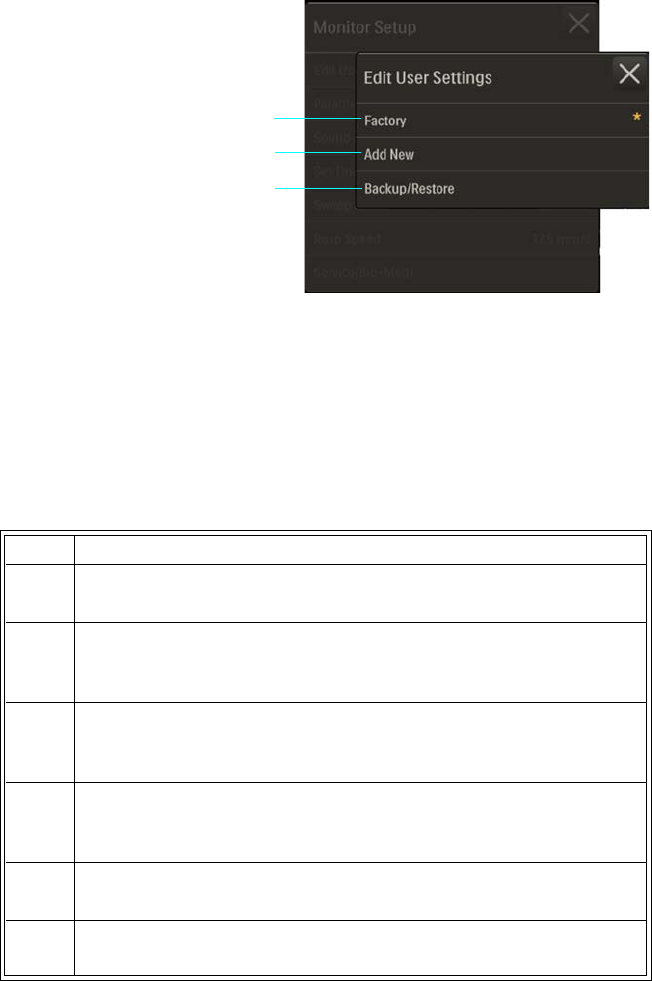
3‐16GettingStartedExpressionMR400InstructionsforUse
PresstheSetupkeyandthentheMonitor
key.OntheMonitorSetupmenu,selectEdit
UserSettings.
Thefollowingoptionsareavailable:
•Factoryrecallsthefactorysettings
frommemory,whichcannotbemodified.(Default)
•AddNewallowsyoutoassignafilename,selectadefaultsetting,andstoreacurrent
setupinthememory(uptotensetupscanbestored);seepage3‐7formoreinformation.
•Backup/RestoreallowsyoutobackupandrestoresettingsusingaUSBflashdrive;seethe
servicemanual(REF989803181911)fordetails.
Toaddandsavenewusersettings
1Factory
2 Add New
3 Backup/Restore
Step Action
1 SetuptheMR400fortheconfigurationtowhichthesesettingswill
pertain.
2PresstheSetupkeyandthentheMonitorkey.
TheMonitorSetupmenuappears.Currentsettingsaredisplayed.
3OntheMonitorSetupmenu,selectEditUserSettings.
TheEditUserSettingsmenuappears.
4 SelectAddNew.
Thesoftkeyboardappears.
5 Enterauniquefilename(ofuptotwentycharacters)fortheuser
settingsusingthesoftkeyboard.
6PresstheCaptureSettingsbuttontoenterthecurrentsetupdata.
1
2
3

ExpressionMR400InstructionsforUseGettingStarted3‐17
Toeditsavedusersettings
Todeletesavedusersettings
7Ifdesired,presstheSettoDefaultbuttontosavethecurrentfileas
thedefaultsetupforuseatpower‐up.
Warning
WARNING
If you choose to boot the device from a user settings
file, confirm that alarm presets are appropriate for the
patient prior to monitoring. Failure to do so may cause
false or missed alarm conditions.
8PresstheSave&Closebuttontosavethecurrentsetupandexit
themenu.
Awarningboxwillappear,promptingyoutoacceptthechanges:
presstheAcceptbuttontosavethecurrentsettings,orpressthe
Cancelbuttontorejectthechanges.
Step Action
1ConfiguretheMR400forthedesiredsettings.
2OntheMonitorSetupmenu,selectEditUserSettings.
3 Selectthefilenamethatyouwanttochange.
4PresstheCaptureSettingsbuttontochangetheusersetuptothe
currentsettings.
5PresstheSave&Closebuttontosavethecurrentsetup.
Awarningboxwillappear,promptingyoutoacceptthechanges—
pressAccepttosavethecurrentsettingsorpressCanceltoreject
thechanges.
Step Action
1OntheMonitorSetupmenu,selectEditUserSettings.
2 Selectthefilenamethatyouwantdelete.
Step Action
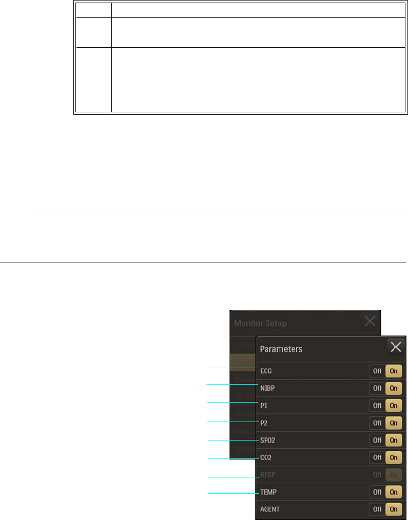
3‐18GettingStartedExpressionMR400InstructionsforUse
Parameters
Controlsmonitoringfunctions,asindicatedbytheabsenceorpresenceoftheVSboxforthe
parameter,exceptECG(seebelow).
NOTE
Some parameters require optional equipment that may not be enabled or present on your system;
see System Config for details.
ToopentheParametersmenu
PresstheSetupkeyandthentheMonitor
key.OntheMonitorSetupmenu,select
Parameters.
Thefollowingparametersareavailable:
•ECGallowselectrocardiogrammonitoring:
–OffturnsofftheECGparameter.(Heartrate(HR)willremainintheVSbox,allowingit
tobedisplayedfromanothersourceorifHRSourceissettoAuto.)
3PresstheDeleteSettingskey.
4PresstheSave&Closebuttontosavethecurrentsetup.
Awarningboxwillappear,promptingyoutoacceptthechanges—
pressAccepttosavethecurrentsettingsorpressCanceltoreject
thechanges.
1ECG
2NIBP
3P1
4P2
5SPO2
6CO2
7RESP
8TEMP
9AGENT
Step Action
1
2
3
4
5
6
7
9
8

ExpressionMR400InstructionsforUseGettingStarted3‐19
–OnturnsontheECGparameter.(Default)
•NIBPallowsnon‐invasivebloodpressuremonitoring(doesnothaveanassociated
waveform):
–OffturnsofftheNIBPparameter.
–OnturnsontheNIBPparameter.(Default)
•P1allowsinvasivebloodpressuremonitoring:
–OffturnsofftheP1parameter.(Default)
–OnturnsontheP1parameter.
•P2allowsinvasivebloodpressuremonitoring:
–OffturnsofftheP2parameter.(Default)
–OnturnsontheP2parameter.
•SPO2allowsoxygensaturationofarterialbloodmonitoring:
–OffturnsofftheSPO2parameter.
–OnturnsontheSPO2parameter.(Default)
•CO2allowsCO2andCO2‐derivedrespirationratemonitoring:
–OffturnsofftheCO2parameter.(Default)
–OnturnsontheCO2parameter.
NOTE
If CO2 is turned Off, AGENT and GAS will also be deactivated.
•RESPallowsrespirationratemonitoringusingthebellows(doesnothaveanassociated
waveform):
–Offturnsoffthebellows‐derivedrespirationparameter.(Default)
–Onturnsonthebellows‐derivedrespirationparameter.
NOTE
If CO2-derived respiration is on, then RESP will not be selectable. To use bellows respiration,
select BEL in the RESP menu; see page 10-5.
•TEMPallowstemperaturemonitoring(doesnothaveanassociatedwaveform):
–Offturnsoffthetemperatureparameter.(Default)
–Onturnsonthetemperatureparameter.
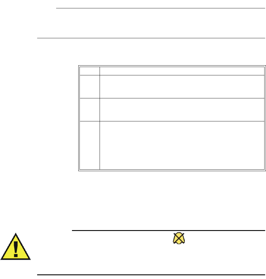
3‐20GettingStartedExpressionMR400InstructionsforUse
•AGENTallowsanestheticagentandgasmonitoring(butdoesnothaveanassociated
waveform),andCO2andCO2‐derivedrespirationratemonitoring:
–OffturnsofftheAGENTparameter.(Default)
–OnturnsontheAGENTparameter.
NOTE
When AGENT is turned on, CO2 will also be activated, including GAS; however, if AGENT is
then turned Off, CO2 will remain active.
Tocontrolparameters
Sound Adjust
Controlsalarm,heartrateandtouchscreentones,andthevolumesettingsforthesounds
generatedbytheMR400.
Warning
WARNING
The alarm sound can be turned off, as indicated by the symbol. Always ensure that the
alarm sound setting is appropriate for the monitoring environment and for each patient. The
alarm sound volume is adjustable for suitability to various clinical environments. When you
use the MR400, always ensure that the alarm sound can be heard above the ambient noise
level; otherwise, treatment of the patient could be delayed.
ToopentheSoundAdjustmenu
Step Action
1PresstheSetupkeyandthentheMonitorkey.
TheMonitorSetupmenuappears.Currentsettingsaredisplayed.
2OntheMonitorSetupmenu,selectParameters.
TheParametersmenuappears.Currentsettingsaredisplayed.
3Locatetheparameterthatyouwanttocontrolthenselectthe
desiredsetting:
Off
On
Thesettingisentered.Tochangeothersettings,repeatstep3.
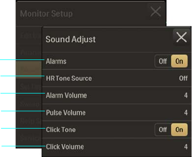
ExpressionMR400InstructionsforUseGettingStarted3‐21
PresstheSetupkeyandthentheMonitor
key.OntheMonitorSetupmenu,select
SoundAdjust.
Thefollowingmenuitemsareavailable:
•Alarmscontrolsthealarmsound(identicaltoandinteractivewithAlarmSoundinthe
Alarmsmenu):
–Offturnsoffthealarmsound,asindicatedbythealarmaudiooffsymbol(seepage4‐
4).(Onlythealarmsoundwillbedisabled;visualalarmindicationswillcontinue.)
–Onturnsonthealarmsound,asindicatedbythealarmaudioarmedsymbol(see
page4‐4).(Default)
•HRToneSourcesetsthesourceusedfortheheartratetone(identicaltoandinteractive
withsameoptionintheECGmenuandSPO2menu):
–Offremovestheheartbeatdetectedsymbolfromthedisplayandsoundsnopulse
tone.(Default)
–QRSprovidestheheartbeatdetectedsymbolandatonetriggeredbytheQRS
detectionfromtheECGvitalsign.
–SPO2providestheheartbeatdetectedsymbolandatonemodulatedbytheSPO2
vitalsign,wherethelowertheSPO2value,thelowerthepitch.
•AlarmVolumesetsthealarmsoundlevelfrom1–10.(Default=4)
•PulseVolumesetsthepulsesoundlevelfrom1–10.(Default=4)
•ClickTonecontrolsanaudioindicationthatisproducedwhenanactiveareaofthetouch
screeniscontacted:
–Offdoesnotproduceaclicktone.
–Onproducesaclicktone.(Default)
•ClickVolumesetstheclicktonesoundlevelfrom1–10.(Default=4)
1Alarms
2 HR Tone Source
3 Alarm Volume
4Pulse Volume
5 Click Tone
6Click Volume
1
2
3
4
5
6

3‐22GettingStartedExpressionMR400InstructionsforUse
Tocontrolthesounds
Set Time & Date
Setsthetimeanddate,andthedisplayedtimeanddateformats;seepage2‐14.
ToopentheSetTime&Datemenu
Step Action
1PresstheSetupkeyandthentheMonitorkey.
TheMonitorSetupmenuappears.Currentsettingsaredisplayed.
2OntheMonitorSetupmenu,selectSoundAdjust.
TheSoundAdjustmenuappears.Currentsettingsaredisplayed.
3 Selectthemenuitemforthesoundfunctionthatyouwantto
control:
Alarms
HRToneSource
AlarmVolume
PulseVolume
ClickTone
ClickVolume
Themenuitemappears.Thecurrentsettingishighlighted.
4 Selectthedesiredsettingfromthemenuoptions(exceptAlarms
andClickTone,whichareselectableontheSoundAdjustmenu.)
Thesettingisentered.
NOTE
When making adjustments to the volume settings, Real Tones
Disabled will be displayed and a momentary sound at the setting
level will be produced. To your save changes and close the menu
select .
5Tochangeothersettings,repeatsteps3and4.
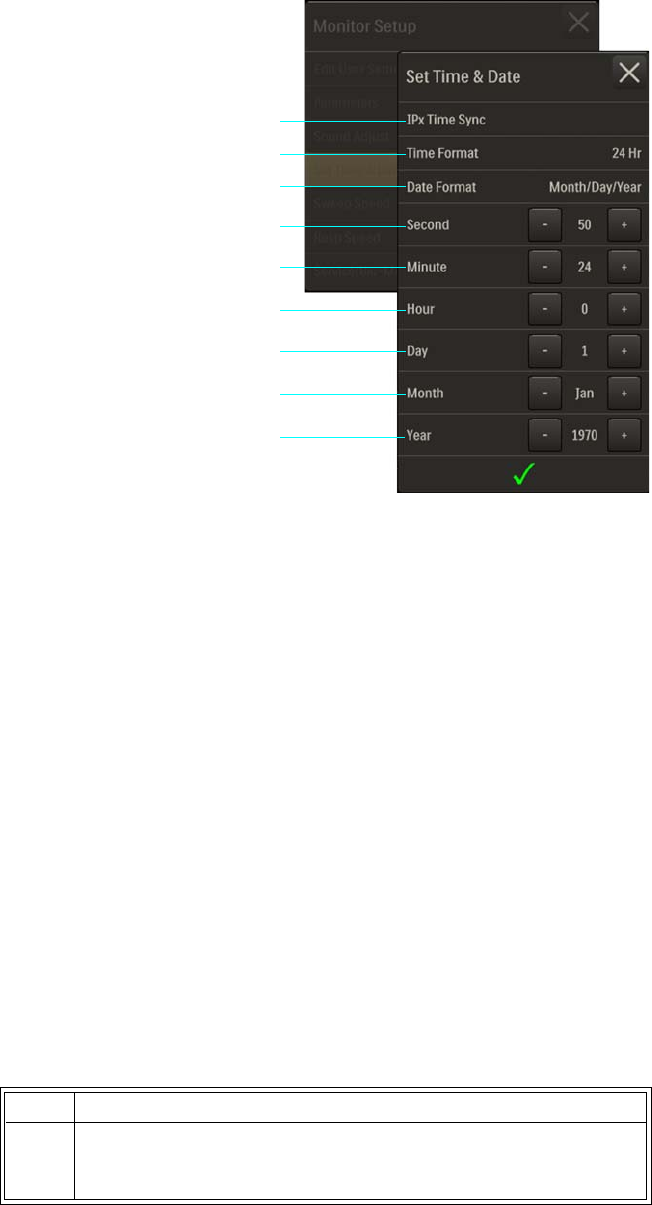
ExpressionMR400InstructionsforUseGettingStarted3‐23
PresstheSetupkeyandthentheMonitorkey.
OntheMonitorSetupmenu,selectSetTime
&Date.
Thefollowingmenuitemsareavailable:
•IPxTimeSyncsynchronizesthetimeanddatesettingsoftheMR400tothatofanIP5(IP5
optionrequired).
•TimeFormatchangestheformatofthedisplayed(andprinted)hours:minutes:seconds
(hh:mm:ss):
–12Hrusesthe12‐hour(hh)convention(01–12)withtheAMorPMdesignation.
–24Hrusesthe24‐hour(hh)convention(00–23).(Default)
•DateFormatchangestheformatofthedisplayed(andprinted)date:
– Month/Day/Year:Usesa<mm>/<dd>/<yyyy>format
– Day/Month/Year:Usesa<dd>/<mm>/<yyyy>format
–MonthDay,Year:Usesa<mname><dd>,<yyyy>format
•Secondscrollsthesecondcounter.
•Minutescrollstheminutecounter.
•Hourscrollsthehourcounter.
•Dayscrollsthedaycounter.
•Monthscrollsthemonthcounter.
•Yearscrollstheyearcounter.
Tosettheformatofthedisplayedtimeordate
1IPx Time Sync
2Time Format
3 Date Format
4Second
5 Minute
6Hour
7Day
8Month
9Year
Step Action
1PresstheSetupkeyandthentheMonitorkey.
TheMonitorSetupmenuappears.Currentsettingsaredisplayed.
2
3
4
5
6
7
8
9
1

3‐24GettingStartedExpressionMR400InstructionsforUse
Tosetthetimeordate
2OntheMonitorSetupmenu,selectTimeandDate.
TheTimeandDatemenuappears.Currentsettingsaredisplayed.
3 Selectthemenuitemforthetimeordatefunctionthatyouwant
tochange:
TimeFormat
DateFormat
Themenuitemappears.Thecurrentsettingishighlighted.
4 Selectthedesiredsettingfromthemenuoptions.
Thesettingisentered.
5Tochangeothersettings,repeatsteps3and4.
Step Action
1PresstheSetupkeyandthentheMonitorkey.
TheMonitorSetupmenuappears.Currentsettingsaredisplayed.
2OntheMonitorSetupmenu,selectTimeandDate.
TheTimeandDatemenuappears.Currentsettingsaredisplayed.
3Usethearrowkeysassociatedwitheachtimeordatefunctionthat
youwanttochange(leftarrowdecreasesthesetting,rightarrow
increasesthesetting):
Second
Minute
Hour
Day
Month
Year
Thesettingischanged.
4Toadjustothersettings,repeatstep3.
5Whenfinished,selectthecheckmark.
Thechangesaresavedandthedisplayedtimeisadjusted.
Step Action
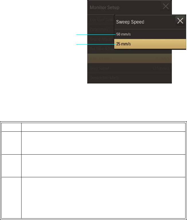
ExpressionMR400InstructionsforUseGettingStarted3‐25
Sweep Speed
Setsthesweeprateforallwaveforms(displayedandprinted),exceptCO2.
ToopentheSweepSpeedmenu
PresstheSetupkeyandthentheMonitor
key.OntheMonitorSetupmenu,select
SweepSpeed.
Thefollowingspeeds(inmillimetersper
second)areavailable:
•50mm/s
•25mm/s(Default)
Toadjustthesweeprateforallwaveforms(exceptCO2)
Resp Speed
SetsthesweepratefortheCO2waveform.
ToopentheRespSpeedmenu
1 50 mm/s
2 25 mm/s
Step Action
1PresstheSetupkeyandthentheMonitorkey.
TheMonitorSetupmenuappears.Currentsettingsaredisplayed.
2OntheMonitorSetupmenu,selectSweepSpeed.
TheSweepSpeedmenuappears.Thecurrentsettingishighlighted.
3 Selectthedesiredsettingfromthemenuoptions:
50mm/s
25mm/s
Thesettingisentered.
1
2
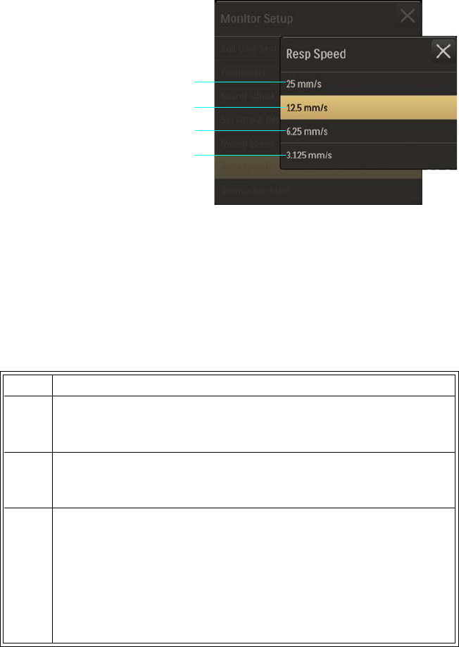
3‐26GettingStartedExpressionMR400InstructionsforUse
PresstheSetupkeyandthentheMonitor
key.OntheMonitorSetupmenu,selectResp
Speed.
Thefollowingspeeds(inmillimetersper
second)areavailable:
•25mm/s
•12.5mm/s(Default)
•6.25mm/s
•3.125mm/s
ToadjustthesweepratefortheCO2waveform
Service(Bio-Med)
Accessesasub‐menuthatcontainssoftwareandfirmwareinformationaboutthesystem,and
optionsforNIBPandP1(andP2)pressures,diagnosticsandconfiguration.
ToopentheService(Bio‐Med)menu
1 25 mm/s
2 12.5 mm/s
3 6.25 mm/s
4 3.125 mm/s
Step Action
1PresstheSetupkeyandthentheMonitorkey.
TheMonitorSetupmenuappears.Currentsettingsaredisplayed.
2OntheMonitorSetupmenu,selectRespSpeed.
TheRespSpeedmenuappears.Thecurrentsettingishighlighted.
3 Selectthedesiredsettingfromthemenuoptions:
25mm/s
12.5mm/s
6.25mm/s
3.125mm/s
Thesettingisentered.
1
2
3
4
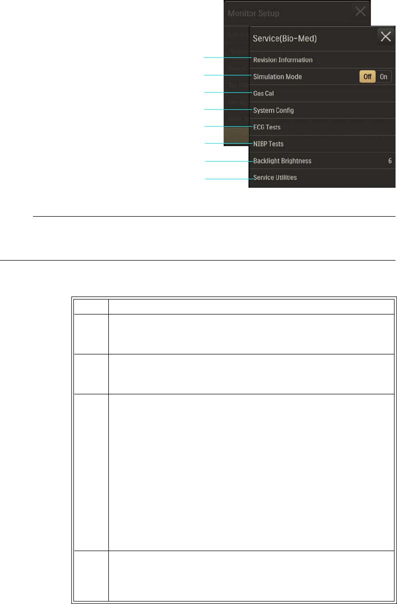
ExpressionMR400InstructionsforUseGettingStarted3‐27
PresstheSetupkeyandthentheMonitor
key.OntheMonitorSetupmenu,select
Service(Bio‐Med).
NOTE
Some menu items require entry of a password for access; see page 2-23.
ToaccesstheSERVICE(BIO‐MED)menuitems
1 Revision Information
2 Simulation Mode
3Gas Cal
4 System Config
5ECG Tests
6NIBP Tests
7 Backlight Brightness
8 Service Utilities
Step Action
1PresstheSetupkeyandthentheMonitorkey.
TheMonitorSetupmenuappears.Currentsettingsaredisplayed.
2OntheMonitorSetupmenu,selectService(Bio‐Med).
TheService(Bio‐Med)sub‐menuappears.
3 Selectthedesiredmenuitem(somemenusarepassword
protected):
RevisionInformation
SimulationMode
GasCal
SystemConfig
ECGTests
NIBPTests
BacklightBrightness
ServiceUtilities
Theselectionisentered(orenterthecorrectpasswordforaccess).
4 Selectthedesiredmenuoritem,exceptSimulationMode,whichis
selectableontheService(Bio‐Med)menu.
Thesettingisentered.
1
2
3
4
5
6
7
8
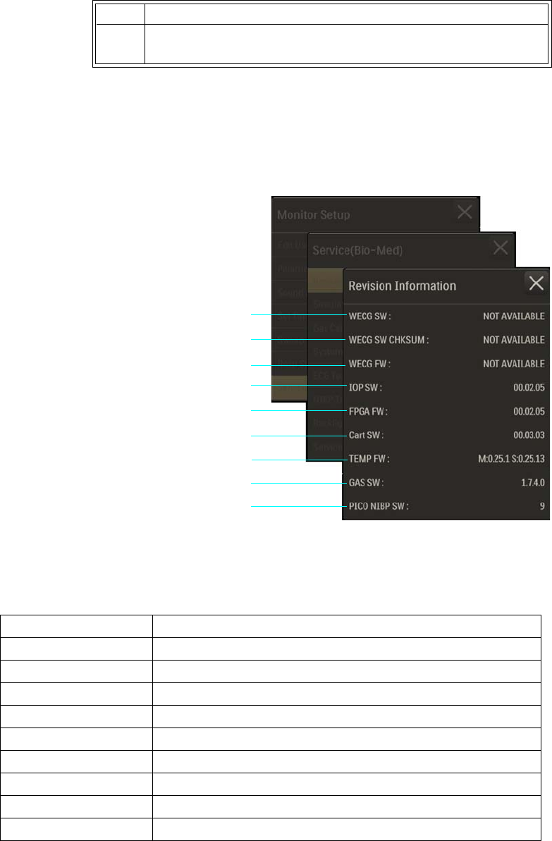
3‐28GettingStartedExpressionMR400InstructionsforUse
Revision Information
Dependingupontheinstalledoptions,displaysrevisioninformationforthesoftwareand
firmwareusedintheMR400andwirelessmodules.
Toviewtherevisioninformation
PresstheSetupkeyandthenthe
Monitorkey.OntheMonitorSetup
menu,selectService(Bio‐Med).Onthe
Service(Bio‐Med)menu,selectRevision
Information.
ThedefinitionsfortheitemsdisplayedinRevisionInformationareprovidedbelow.
5Tochangeothersettings,repeatsteps2,3and4.
1WECG SW:
2WECG SW CHKSUM:
3WECG FW:
4IOP SW:
5FPGA FW:
6Cart SW:
7TEMP FW:
8GAS FW:
9PICO NIBP SW:
NameDefinition
WECGSW SoftwarerevisionofthewECGmodule
WECGSWCHKSUM ChecksumofthesoftwareofthewECGmodule
WECGFW FirmwarerevisionofthewECGmodule
IOPSW Softwarerevisionoftheinput/outputprocessor
FPGAFW SoftwarerevisionoftheprocessingelementoftheMR400
CartSW SoftwarerevisionoftheMR400cart
TEMPFW FirmwarerevisionofTEMPsystem
GASSW Softwarerevisionofgassystem
PICONIBPSW SoftwarerevisionoftheNIBPsystem
Step Action
1
2
3
4
5
6
7
8
9
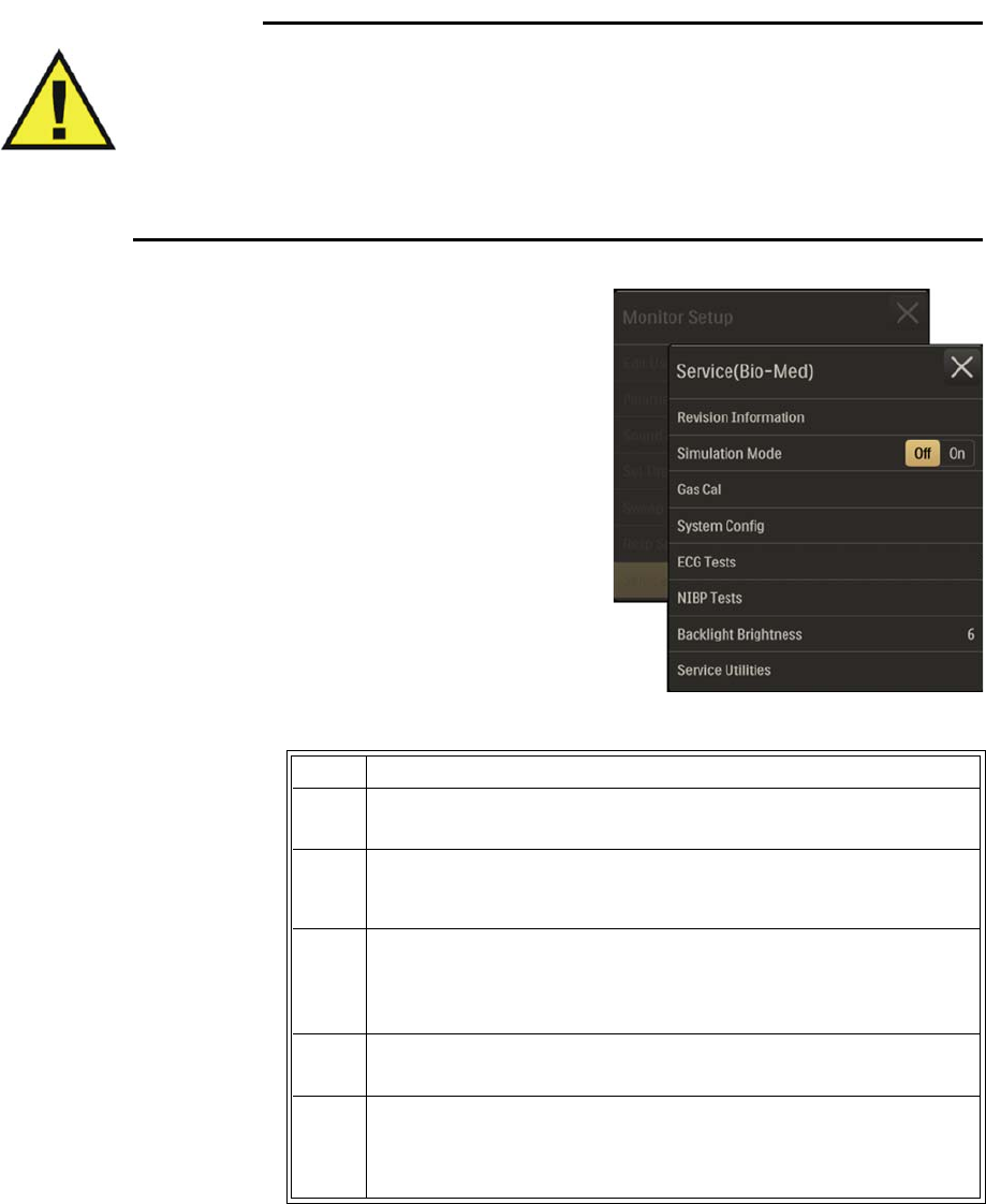
ExpressionMR400InstructionsforUseGettingStarted3‐29
Simulation Mode
Warning
WARNING
The MR400 is equipped with a simulation mode that displays computer generated data for
training or demonstration. As a safety feature, Simulation is displayed and appears on all
printouts while in simulation mode. Do not attach a patient to the MR400 when in simulation
mode and never activate simulation mode when a patient is connected. The MR400 will not
monitor patients while in the simulation mode. Activating simulation mode when a patient is
connected will result in a lapse in patient monitoring and could result in a delay in
treatment.
AllowstheMR400tooperateusinginternally‐
generateddatainsteadofpatientdata.
ToopentheSimulationModemenu
PresstheSetupkeyandthentheMonitorkey.On
theMonitorSetupmenu,selectService(Bio‐Med).
OntheService(Bio‐Med)menu,locateSimulation
ModeandselectOn.Enterthepassword.
Thefollowingcontrolsareavailable:
•Offdisplaysnormalmonitoringfunctions.
(Default)
•Ondisplayssimulationsofmonitoring
functions.
Toentersimulationmode
Toexitsimulationmode,turnoffthepowerswitch.
Step Action
1EnsurethatnopatientisconnectedtotheMR400.
2PresstheSetupkeyandthentheMonitorkey.
TheMonitorSetupmenuappears.Currentsettingsaredisplayed.
3OntheMonitorSetupmenu,selectService(Bio‐Med).
TheService(Bio‐Med)menuappears.Currentsettingsare
displayed.
4LocateSimulationModeandselectOn.
5WhenEnterPasswordisdisplayed,enterthecorrectsix‐digitcode.
Simulationwillbedisplayedinthesystemmessageareaofthe
simulatedscreen.
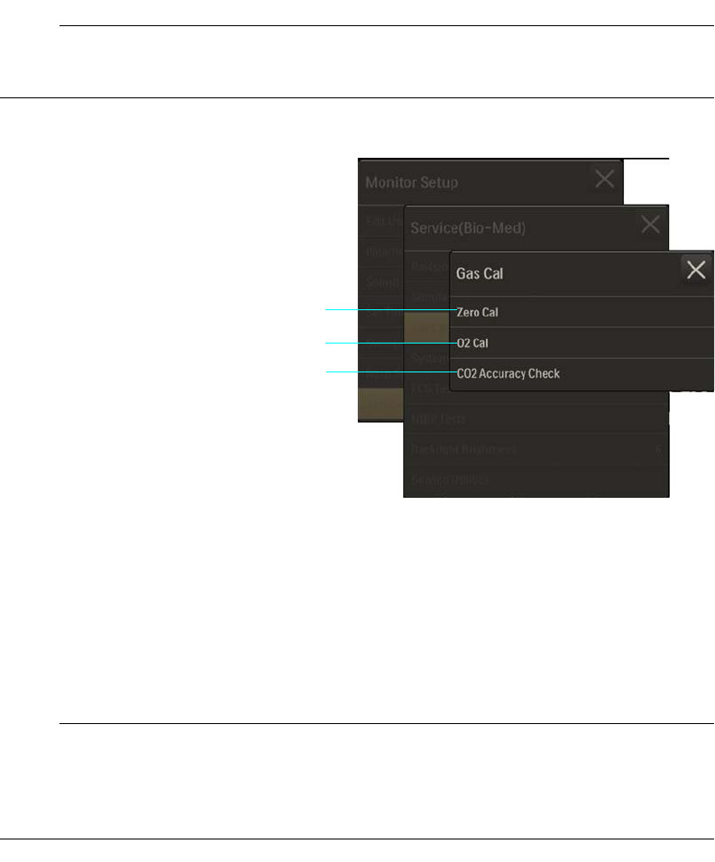
3‐30GettingStartedExpressionMR400InstructionsforUse
Gas Cal
Calibratesthegasfunction(s)whenequippedwiththeCO2ortheAGENToption.
NOTE
As indicated by displayed message, allow any warm-up to complete before calibrating.
ToopentheGasCalmenu
PresstheSetupkeyandthenthe
Monitorkey.OntheMonitorSetup
menu,selectService(Bio‐Med).Onthe
Service(Bio‐Med)menu,selectGas
Cal.
Thefollowingmenuitemsare
available:
•ZeroCalInitiatesazero
calibration(afunctionthat
occursautomaticallyduringnormaluse).ForLoFloCO2optiondetails,seepage7‐2;and
fortheAGENToptiondetails,seepage9‐2.
•O2Calperformsa1‐minutepressurecalibrationoftheO2sensorfortheAGENToption.
Connectionofasamplelineisrequiredforthistest.
•CO2AccuracyCheckteststheLoFloCO2accuracy(a5%gassourcemustbeconnectedto
theMR400).ProvidesaCO2waveformvalue(asapercentage),anatmosphericpressure
readingandanumericCO2value(inmmHg).
NOTE
During the CO2 Accuracy Check, to alert you that the indicated values are not actual patient
measurements, the following message will be displayed: CO2 test in progress. Do not use CO2
values for patient monitoring during test. Pressing close will cancel test.
System Config
ControlstheconfigurationoftheMR400includingoptions,languageandunitofmeasurement
forpressures.
1Zero Cal
2O2 Cal
3 CO2 Accuracy Check
1
2
3
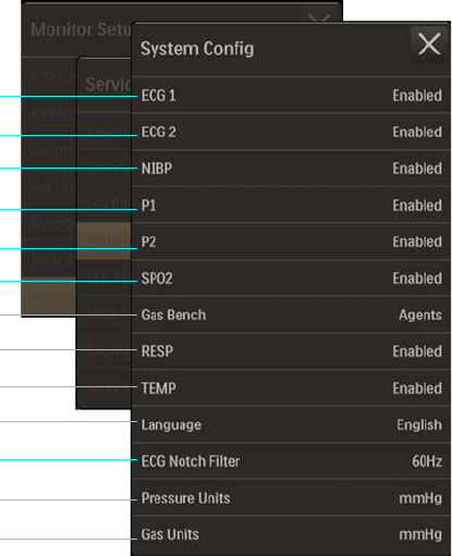
ExpressionMR400InstructionsforUseGettingStarted3‐31
ToopentheSystemConfigmenu
PresstheSetupkeyandthenthe
Monitorkey.OntheMonitorSetup
menu,selectService(Bio‐Med).Onthe
Service(Bio‐Med)menu,selectSystem
Config.
Thefollowingmenuitemsareavailable:
•ECG1configurestheMR400forECG1
•ECG2configurestheMR400forECG2
•NIBPconfigurestheMR400forNIBP
•P1configurestheMR400forP1
•P2configurestheMR400forP2
•SPO2configurestheMR400forSPO2
•GasBenchconfigurestheMR400forthegasbenchoption,whereCO2onlyselectsthe
CO2Loflooption,AgentsselectstheAGENToption
•RESPsetstheconfigurationoftheunitforbellows‐derivedRESP
•TEMPconfigurestheMR400forTEMP
•Languagesetsthelanguageforthedisplayedinformation:
– English(Default)
–Deutsch
–Espanol
– Francais
1ECG 1
2ECG 2
3NIBP
4P1
5P2
6SPO2
7Gas Bench
8RESP
9TEMP
10 Language
11 ECG Notch Filter
12 Pressure Units
13 Gas Units
1
2
3
4
5
6
7
9
8
10
11
12
13
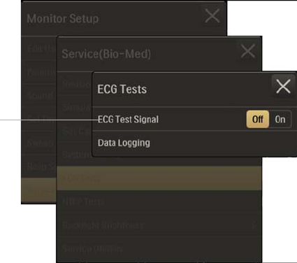
3‐32GettingStartedExpressionMR400InstructionsforUse
–Portuguese
– Italiano
–Dansk
–Svenska
–Norsk
–NLD
•ECGNotchFilterappliesanotchfiltertotheECGsignal:
–Off
–50Hz
–60Hz(Default)
•PressureUnitssetstheunitofmeasureforP1,P2,andNIBPpressurereadings:
–mmHg(Default)
–kPa
•GasUnitssetstheunitofmeasureforCO2pressurereadings:
–mmHg(Default)
–kPa
ECG Tests
AccessestestingfunctionsforECG.
ToopentheECGTestsmenu
PresstheSetupkeyandthenthe
Monitorkey.OntheMonitorSetup
menu,selectService(Bio‐Med).Onthe
Service(Bio‐Med)menu,selectECG
Tests.
Thefollowingmenuitemsare
available:
•ECGTestSignalcontrolsawECG
module‐generated1mVpeak‐
to‐peaksquarewave,where60
BPMwillbedisplayedintheECG
VSboxandECGTestSignalwillbedisplayedinthealarmflagarea(andprintedwhen
outputtotheprinter,ifequipped):
–Offdoesnottransmitthetestsignal.(Default)
–Ontransmitsthetestsignal.
1ECG Signal Test
1

ExpressionMR400InstructionsforUseGettingStarted3‐33
NOTE
ECG Test Signal is unavailable when Filter Mode > Advanced 2 is selected; see 5-31.
TocontroltheECGTestSignal
NIBP Tests
AccessescalibrationandtestingfunctionsforNIBP.
NOTE
If Module Not Calibrated is displayed, then all options in the NIBP Tests menu will be locked
until NIBP is successfully calibrated.
ToopentheNIBPTestsmenu
Step Action
1EnsurethatthewECGmoduleiscommunicatingwiththeMR400.
2PresstheSetupkeyandthentheMonitorkey.
TheMonitorSetupmenuappears.Currentsettingsaredisplayed.
3OntheMonitorSetupmenu,selectService(Bio‐Med).
TheService(Bio‐Med)menuappears.Currentsettingsare
displayed.
4LocateECGTestSignalandselectthedesiredsetting:
Off
On
Thesettingisentered.
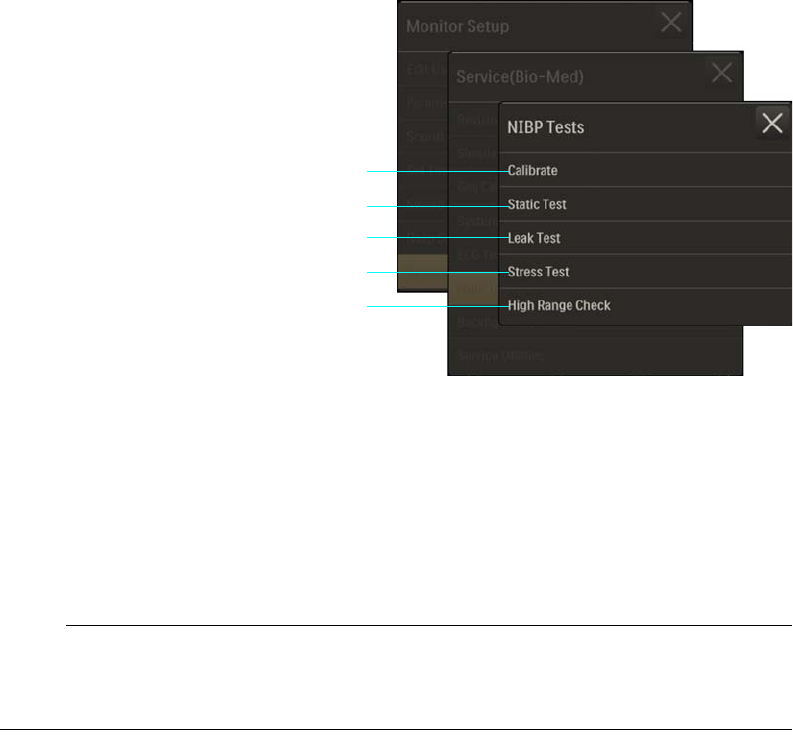
3‐34GettingStartedExpressionMR400InstructionsforUse
PresstheSetupkeyandthenthe
Monitorkey.OntheMonitorSetup
menu,selectService(Bio‐Med).Onthe
Service(Bio‐Med)menu,selectNIBP
Tests.
Thefollowingmenuitemsare
available:
•CalibrateperformscalibrationoftheNIBPsystem.(Passwordrequired)
•StaticTestperformsastaticpressuretestoftheNIBPsystem.(Passwordrequired)
•LeakTestperformsapressureleaktestoftheNIBPsystem(seenotebelow).
•StressTestperformsapressurestresstestoftheNIBPsystem.(Passwordrequired)
•HighRangeCheckperformsahighpressuretestoftheNIBPsystem.(Passwordrequired)
NOTE
If an error is reported while the Leak Test is in progress, the test will be canceled and user will be
prompted with the message: NIBP Bench Error. Press Start to try again.
Toperformthesetests
Seereferencetheservicemanualfordetails.
Backlight Brightness
Adjuststhebrightnessofthetouchscreen.
ToopentheBacklightBrightnessmenu
1 Calibrate
2 Static Test
3 Leak Test
4 Stress Test
5 High Range Check
1
2
3
4
5
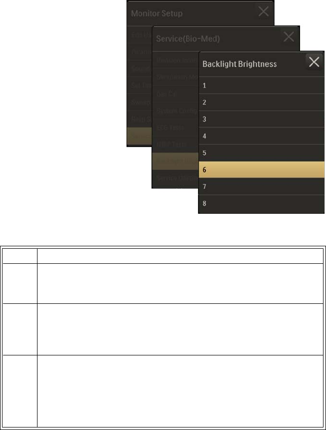
ExpressionMR400InstructionsforUseGettingStarted3‐35
PresstheSetupkeyandthentheMonitor
key.OntheMonitorSetupmenu,select
Service(Bio‐Med).OntheService(Bio‐Med)
menu,selectBacklightBrightness.
Thefollowingbrightnesslevelsareavailable:
•1(Minimum)
•2
•3
•4
•5
•6(Default)
•7
•8(Maximum)
Tocontrolthebrightnessofthedisplaybacklight
Service Utilities
Accessesservice‐relatedfunctions(apasswordisrequiredforaccess).
ToopentheServiceUtilitiesoption
Step Action
1PresstheSetupkeyandthentheMonitorkey.
TheMonitorSetupmenuappears.Currentsettingsaredisplayed.
2OntheMonitorSetupmenu,selectService(Bio‐Med).
TheService(Bio‐Med)menuappears.Currentsettingsare
displayed.
3 SelectBacklightBrightnessandthenenterthedesiredbrightness
level:
1–8
Thesettingisentered.
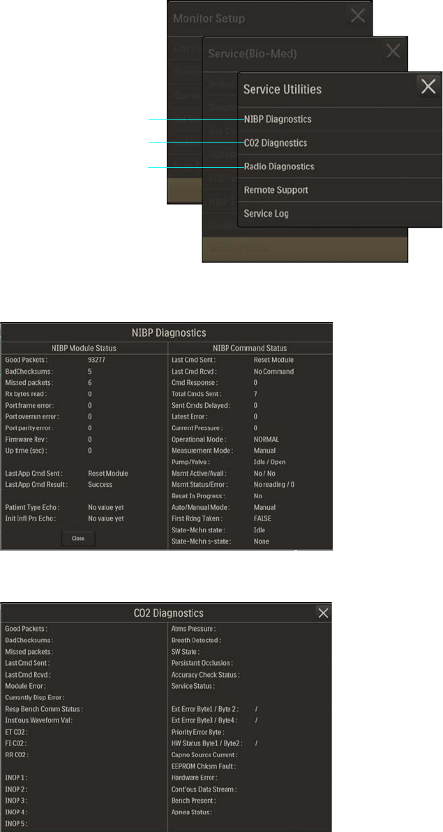
3‐36GettingStartedExpressionMR400InstructionsforUse
PresstheSetupkeyandthenthe
Monitorkey.OntheMonitorSetup
menu,selectService(Bio‐Med).Onthe
Service(Bio‐Med)menu,selectService
Utilities.Enterthepassword.
Thefollowingmenuitemsareavailable:
•NIBPDiagnosticsopensawindowthatdisplaysNIBPdiagnosticdata.
•CO2DiagnosticsopensawindowthatdisplaysCO2diagnosticdata.
1NIBP Diagnostics
2CO2 Diagnostics
3 Radio Diagnostics
1
2
3
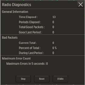
ExpressionMR400InstructionsforUseGettingStarted3‐37
•RadioDiagnosticsopensawindowthatdisplaysradiodiagnosticdata.
3‐38GettingStartedExpressionMR400InstructionsforUse

ExpressionMR400InstructionsforUseAlarms4‐1
CHAPTER 4
Alarms
Thealarminformationhereappliestoallmeasurements.Measurement‐specificalarm
informationisdiscussedinthesectionsonindividualmeasurements.Themonitorprovides
patientalarmsandINOPalarms.
PatientAlarms
Patientalarmswillilluminatearedoryellowalarmlight,wherearedalarmlightindicatesahigh
priorityalarmtoalertyoutopotentiallylifethreateningsituationsforyourpatient(forexample,
adisconnectedcatheter).Ayellowalarmlightindicatesalowerprioritypatientalarm(for
example,arespirationalarmlimitviolation).
Patientalarmsmayalsogenerateflashingnumericvaluesorotherindications,alarmflagsand
soundanaudiblealarm(providedthatahigherpriorityalarmsounddoesnotoverrideit).
Forexample,ifapatient’sheartrateclimbsto71BPM(whichisabovethesettingoftheupper
alarmlimit)aphysiologicalalarmconditionisdeclared.
INOPs
INOPsarestatusandtechnicalalarms—theyindicatethatthemonitorcannotmeasureordetect
alarmconditionsreliably;seepage4‐31foralisting.Dependinguponthenatureofthecondition
detected,INOPswillilluminatethealarmlight,generateanalarmflag,andsoundanaudible
indicatortone(providedthatahigherpriorityalarmsounddoesnotoverrideit).Otherstatus
andtechnicalalarmshaveamediumorhighprioritydependinguponthenatureofthecondition
detected.
MultipleAlarms
Patientalarmsaremutuallyexclusiveandthehighestpriorityalarmwillbeindicatedbythealarm
light;ifahighpriorityalarmandamediumpriorityalarmarepresentsimultaneously.thered
alarmlightwillbeon,buttheyellowalarmlightwillnotbe.
1Medium priority alarm example (ECG heart rate value)
2Violated (high) alarm limit setting
1
2
4‐2AlarmsExpressionMR400InstructionsforUse
Thebluealarmlightcanbeonatthesametimeastheredoryellowalarmlight.Whenanumeric
valuebecomesmissingduetoanINOP,theINOPalarmwillbepresentaswellasthepatient
alarm(duetothemissingvalue),withbothoriginatingfromthesamecause.
AlarmDelays
Thereisanalarmsoundandanalarmlightilluminationdelayofnomorethan4secondsfollowing
thedisplayedalarmflag,providedthatthealarmconditionstillexistsafterthisdelay.
Alarm Safety Information
WARNINGS
• The monitor detects and responds almost immediately to most out-of-limits conditions,
except when averaging of the physiological signal is required to reduce unwanted noise
signals (for example, respiration rates and measurements derived from SpO2 signals.)
• Set the alarm volume based upon the ambient noise levels in the MR environment.
Some areas in the MR environment, such as the MR system room, may have ambient
noise levels louder than the maximum volume of the MR400. Therefore, displayed data
should be continuously monitored. Otherwise, if sound was inaudible, treatment of the
patient could be delayed. For visual alarms, adjust the position of the MR400 so that
you maintain a clear view of the display.
Visual Alarm Indications
Dependinguponthealarmcondition,visualalarmindicationscanincludeanalarmflag,a
flashingnumeric,andanilluminatedalarmlight;whenmultiplealarmsaredetected,multiple
visualindicationsmaybepresented.
Alarm Flags
Alarmflagsarevisualindicatorsthatcontainanalarmmessagedisplayedonabackgroundcolor
thatidentifiesthepriorityofthealarm(seetablebelow).Analarmflagisdisplayedforthe
durationofanalarmcondition.Multiplealarmflagsaredisplayedwhenmultiplealarm
conditionsexist.
AlarmPriority DisplayedBackgroundColor
High(patientalarm) Red
Medium(patientalarm) Yellow
INOP(statusortechnicalalarm) Blue
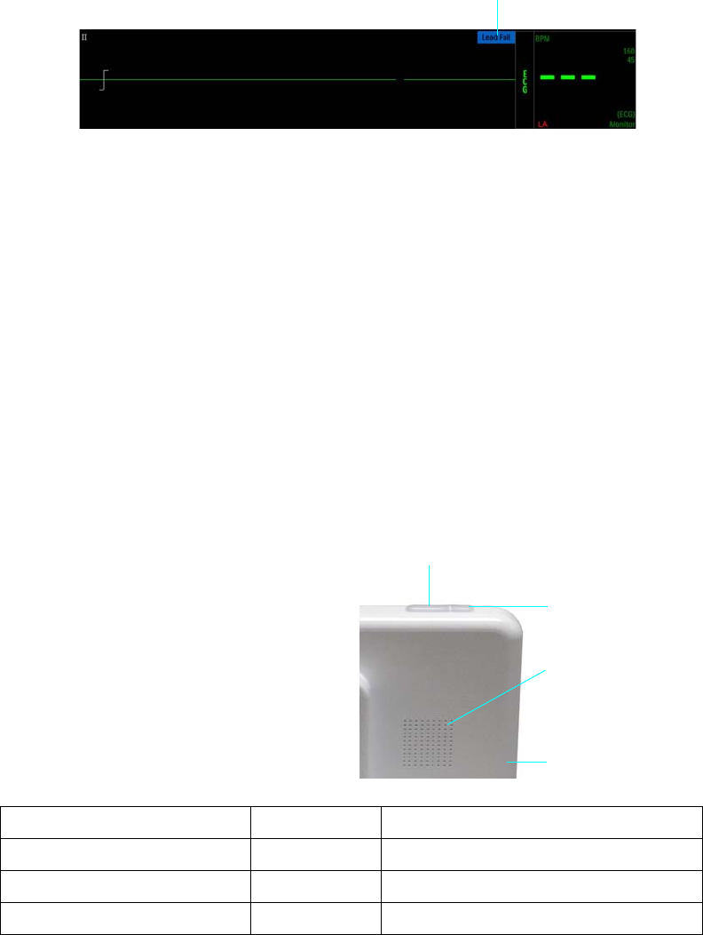
ExpressionMR400InstructionsforUseAlarms4‐3
AlarmflagsassociatedwithavitalsignaredisplayedalongsidetheVSboxofthatparameter(see
illustrationbelow),whilealarmflagsassociatedwiththesystemaredisplayedinthesystem
messagearea(middleandtopcenterofthetouchscreen,seepage2‐21).Whenmultiplealarm
flagsarepresent,theywillbestackedinacolumn.
Flashing Numeric
Duringanpatientalarmcondition,thevitalsignnumericwillchangecolorandflashtoindicate
thesource,typeandpriorityofthealarm:
•Highprioritypatientalarm—rednumeric,flashingat1.5Hzwitha50%dutycycle.
•Mediumprioritypatientalarm—yellownumeric,flashingat0.75Hzwitha50%dutycycle.
Whiletheviolationcontinues,thenumericoftheviolatedparameterwillflashinprioritycolorof
thedetectedalarm.
Alarm Light
Duringanalarmcondition,thealarmlight(see
inset)canilluminatetoprovidea360degree,
visualindicationofthealarmpriority,asdetailed
inthetablebelow.
Multiplecolorscanbeilluminatedwhen
multiplealarmconditionsexist.Thealarmlight
isamenu‐controlledfeature;seepage4‐20for
settingdetails.
1Alarm flag (an INOP in this example)
1
AlarmPriority LightColor Indication
High(patientalarm) RedFlashing,1.5Hzwitha50%dutycycle
Medium(patientalarm) YellowFlashing,0.75Hzwitha50%dutycycle
INOP(statusortechnicalalarm) Blue Steady
Alarm light, red or yellow
Alarm light, blue
Speaker
Display panel
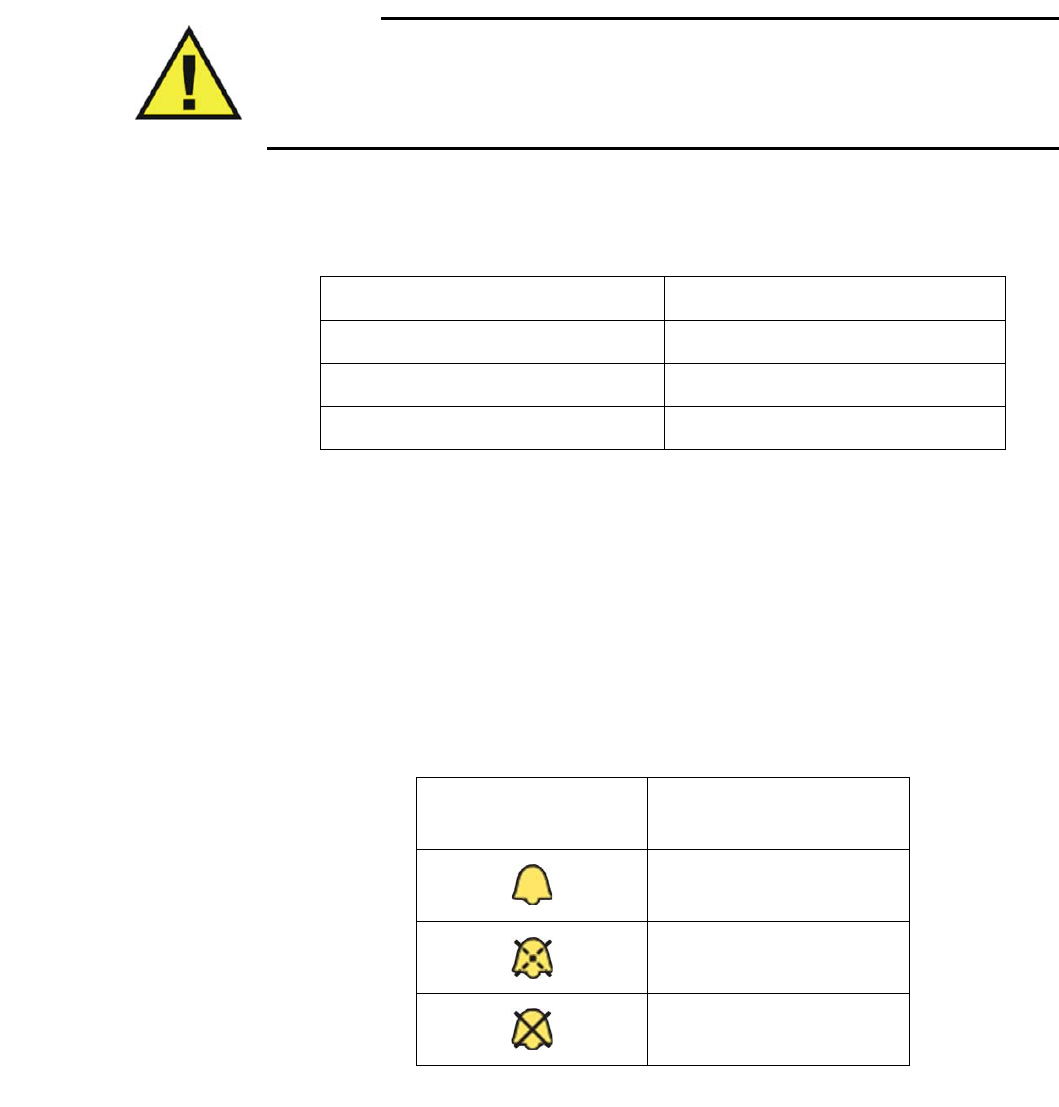
4‐4AlarmsExpressionMR400InstructionsforUse
Audible Alarm Indications
WARNING
Do not rely exclusively on the audible alarm system for patient monitoring. Adjustment of
alarm volume to a low level or off during patient monitoring may result in patient danger.
Remember that the most reliable method of patient monitoring combines close personal
surveillance with correct operation of monitoring equipment.
Dependingupontheseverityandtypeofthealarmcondition,alarmprioritytoneswithdistinct
pitchesaresoundedbythespeaker(seeillustrationonpage4‐3).Whenmultiplealarmsare
detected,thehighestpriorityalarmisannounced.
Onceactivated,anaudiblealarmindicationcontinuesaslongasthealarmconditionispresentor
untilyouacknowledgethealarmbypressingtheAudioPausekeyortheAlarmkey(orbyplacing
theMR400insuspendmode).
Alarm Sound State Indication
Dependinguponthecurrentsetting,oneofthreepossiblesymbolsareprovidedtoindicatethe
alarmsoundstate,whichisdisplayedatalltimesintheinformationbar(seepage2‐14).Symbol
definitionsforthealarmsoundstateareprovidedinthetablebelow.
Alarm priority Fixed Pitch Mnemonic Notes
High c c c – c c
Medium c c c
INOP e c
Displayed Symbol Alarm Sound State
Alarm audio armed
Alarm audio paused
Alarm audio off
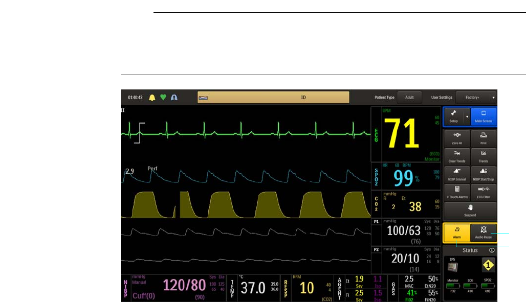
ExpressionMR400InstructionsforUseAlarms4‐5
Initial Audible Alarm Setting Indications
Afterpower‐upandimmediatelyfollowingtherecallofastoredsetup,theMR400providesan
indicationofthealarmvolumebysoundingthealarmtoneatitscurrentlyadjustedsettingfor5
secondsandbydisplayingCheckAlarmVolume.
Audiopausedistheinitialalarmstateandthen,followingawaitperiodof120seconds,armed
becomesthenormalalarmstate,where:
•Analarmwillsoundwhileanalarmconditionexists,providedthatanypre‐alarmsound
delayhasexpiredandthatthealarmaudioarmedsymbolisdisplayed.
•Alarmflagsrelatedtootheralarmsoundstateswillberemovedfromthedisplay.
•Analarmconditionnotpreviouslyplacedinanalarmaudiooffstatewillcausethealarmto
sound.
Controlling the Alarm Audio and Light Indications
Alarmaudioindicationsandthealarmlightcanbecontrolledtomeetthedesiredlevelof
responseusingtheAudioPausekeyortheAlarmkey.
Note
When an alarm is indicated, always confirm the alarm conditions with clinical observations of the
patient before administering interventions. Failure to do so may result in inappropriate
intervention.
1Audio Pause key
2Alarm key
1
2

4‐6AlarmsExpressionMR400InstructionsforUse
Audio Pause Mode
Audiopausemodecanisusefultotemporarilysilencealarmsandtotemporarilyextinguishthe
alarmlight(forexample,whenchangingECGleadsorduringotheruseractivitiesthatmightcause
a“false”alarm).
AudiopausemodeisindicatedwhentheAudioPausedalarmflag,theaudiopausedsymbol(see
page4‐4)andacountdowntimeraredisplayed.(The120‐secondcountdowntimerperiodisnot
useradjustable.)Duringthisperiod,theaudiblealarmwillbesuspendedforanynewalarm
conditionsthatoccur.Anymessagesrelatedtootheralarmsoundstateswillberemoved.
ToactivateAudioPause
PresstheAudioPausekey:
•Ifthealarmisnotsounding,pressthekeyonce.
•Ifthealarmissounding,pressthekeytwice.
TodeactivateAudioPause
•Waituntilthe120‐secondcountdownreacheszero(0),or
•PresstheAudioPausekey.
Audio Off Mode
Inaudiooffmode,thealarmtonewillcease,thealarmlightwillbeextinguished,andtheAudio
Offmessageandtheaudiooffsymbol(seepage4‐4)willbedisplayed.Anynewalarmcondition
willcauseaudiooffmodetobeexitedandthealarmtonetobesounded.However,acurrent
alarmconditionpreviouslysilencedwillnotsoundagainunlesstheconditionreturnswithinlimits
andthenviolatesalimitagain.
Audiooffmodeallowsyoutodisablethealarmtoneandalarmlightduringanalarmcondition,
whileallowingnewalarmconditionstoreactivateallalarmfunctions.Whiletheviolation
continues,thenumericoftheviolatedparameterwillflashinprioritycolorofthedetected
alarm.
WARNING
An active silenced alarm may not be accompanied by the Audio Off message and symbol
, if Audio Paused has been activated, or if a subsequent additional alarm has occurred
and was self-corrected.
ToactivateAudioOff
PresstheAlarmkey.
TodeactivateAudioOff
PresstheAlarmkeyagain.

ExpressionMR400InstructionsforUseAlarms4‐7
Alarm Volume
Theloudnessofthealarmsoundscanbeadjusted(45–86dB,typical).
WARNING
Always ensure that the alarm sound setting is appropriate for each patient. The alarm sound
volume is adjustable for suitability to various clinical environments. When you use the
MR400, always ensure that the alarm sound can be heard above the ambient noise level.
Failure to do so may cause a lapse in patient monitoring.
Tocontrolthealarmvolume
Alarm Reset
Resettingthealarmresultsinthefollowingalarmsystembehaviors:
•Theauditoryalarmsignalsofphysiologicalalarmconditionscease,enablingthealarm
systemtorespondtoasubsequentalarmcondition.
•Alarmlightindicationscease.
•Alarmflagsforanyexistingalarmscontinueaslongasthosealarmconditionsexist.
•Thealarmsystemisenabledimmediatelysothatitcanrespondtoasubsequentalarm
condition.
•ThevisualalarmsignalsofINOPconditionsdonotceaseaslongastheINOPalarm
conditionexists.
ThealarmcanberesetbypressingtheAudioPausekeyonetime.
Step Action
1PresstheSetupkeyandthentheMonitorkey.
TheMonitorSetupmenuappears.Currentsettingsaredisplayed.
2OntheMonitorSetupmenu,selectSoundAdjust.
TheSoundAdjustmenuappears.Currentsettingsaredisplayed.
3 SelectAlarmVolume.
1–10
Themenuitemappears.Thecurrentsettingishighlighted.
4 Selectthedesiredsettingfromthemenuoptions.
Thesettingisenteredandamomentarysoundatthe
correspondinglevelisproduced

4‐8AlarmsExpressionMR400InstructionsforUse
Managing Alarm Functions
WARNINGS
• Always respond promptly to any alarm condition; otherwise, treatment of the patient
could be delayed.
• You should ensure that the current alarm preset is appropriate prior to use on each
patient. Failure to do so may cause a lapse in patient monitoring.
• Setting the alarm limits to extreme values can render alarm monitoring useless. Also,
potential hazard can exist if different alarm monitoring settings are used for the same
or similar equipment in any single patient care unit. Ignoring these restrictions may
cause a lapse in patient monitoring.
TheMR400canbesettoprovidevisualalarmsignalsonly,orbothvisualandaudiblealarm
signals.Theaudiblealarmstateswillhavenoeffectonanyofthevisualalarmsdisplayedbythe
MR400(orIP5,ifequipped).
AllsettingsintheAlarmsmenu(exceptAlarmSound)canbestoredandrecalled.
Restrictionstoalarmpresetsarenotprovidedduetothefastpacedworkflow,shortaverage
durationtimeofMRIscans,differentpatienttypesscheduledforMRIprocedures,anddirect
patientsupervisionprovidedduringMRIprocedures.
Note
If the MR400 is networked to an IP5, alarm indications occur at both the MR400 and the IP5; and
control of alarms, including sound level, is localized to the device (MR400 or IP5) indicating the
alarm condition.
Showing or Hiding Current Alarm Limits
CurrenthighandlowalarmlimitsettingsaredisplayedintheVSboxofeachmonitored
parameterbydefault(exceptbellows‐derivedrespiration).
Tocontrolthedisplayfunctionforthealarmlimitsettings
Step Action
1PresstheSetupkeyandthentheAlarmskey.
TheAlarmsmenuappears.Currentsettingsaredisplayed.

ExpressionMR400InstructionsforUseAlarms4‐9
Adjusting the Alarm Limits
WARNING
Alarm limits can be set to a wide range of values, including off (with the exception of O2,
N2O and FiCO2). It is the responsibility of the operator of the MR400 to ensure that alarm
limit values appropriate for each patient are established and set. Failure to do so may cause
a lapse in patient monitoring.
TheMR400providesversatilemethodstocontrolthesettingsforthepatientparameteralarms.
Eachpatientparameter(withtheexceptionofbellowsrespiration)hasalowandhighalarmlimit
setting(seethetableonpage4‐22),whichcanbechangedmanuallyorautomatically,unlessthe
parameterisoff.
Alarm Limit Controls
Individualalarmlimitsettingscanbeadjustedbytouchingtherespectiveparameterlabelinthe
AlarmsortheGasAlarmsmenu.
2 SelectLimitsDisplay.
TheLimitsDisplaymenuappears.Thecurrentsettingis
highlighted.
3 Selectthedesiredoptionfordisplayofthealarmlimitsettings:
Off
On
Thesettingisselected.
Step Action
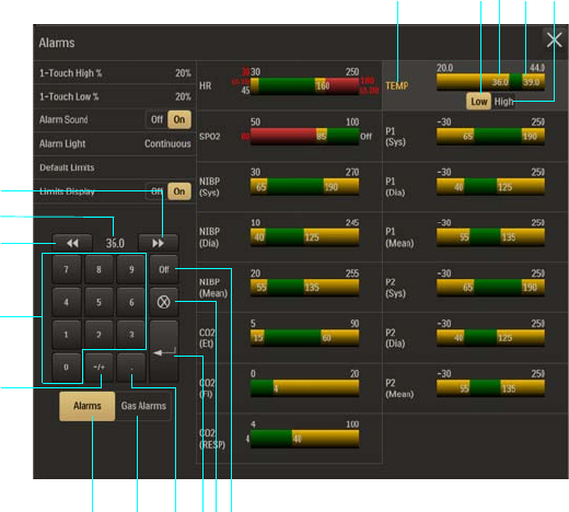
4‐10AlarmsExpressionMR400InstructionsforUse
1Parameter label for alarm limit settings (active adjustment shown)
2Low button
3Lower alarm limit setting
4Upper alarm limit setting
5High button
6Off button
7Clear entry button
8Enter button
9 Decimal point button
10 Gas Alarms button
11 Alarms button
12 Plus / minus button
13 Keypad
14 Decrement button
15 Current adjustment
16 Increment button
13245
8
15
11 9
13
14
7 6
16
12
10
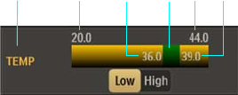
ExpressionMR400InstructionsforUseAlarms4‐11
The Alarm Window
Alarmlimitshaveminimumandmaximumvaluesthatarenotadjustable(seepage4‐22).Within
theminimumandmaximumalarmlimits,adjustablelowerandupperlimitsettingsestablishan
alarmwindow.Vitalsignmeasurementsthatfallwithinthealarmwindowwillnotresultinan
physiologicalalarm.Itisonlywhenavitalsignmeasurementexceedsthealarmwindowfora
monitoredparameterthataphysiologicalalarmwillbedeclared.(Anillustrationisshownbelow.)
Advanced Alarm Functions
TheMR400featuresadvancedalarmfunctionsthatcanalertyoutospecificormoreextreme
physiologicalconditions.Whenadjustingtheseadvancedfunctionalarms,thefollowingrules
governthealarmsettings:
ExtremeBradycardiaAlarmSetting
TheExtremeBradycardiaalarmsettingisestablishedbythesettingoftheExtremeBradycardia
deltavalue.TheExtremeBradycardiadeltavaluecannotbegreaterthanthedifferencebetween
theHRlowalarmlimitsettingandthealarmlimitminimum.Themaximumallowabledeltavalue
is50.Seepage5‐24forsettingdetails.
TheExtremeBradycardiadeltavaluewillretainitsadjustedvalueastheHRlowalarmlimit
settingisadjustedupward,butwillbegintoshrinkinvalueasthelowalarmlimitsettingis
adjustedclosertothealarmlimitminimum.
ExtremeTachycardiaAlarmSetting
TheExtremeTachycardiaalarmsettingisestablishedthesettingoftheExtremeTachycardia
deltavalue.TheExtremeTachycardiadeltavaluecannotbegreaterthanthedifferencebetween
theHRalarmlimitmaximumandthehighalarmlimitsetting.Themaximumallowabledelta
valueis50.Seepage5‐24forsettingdetails.
1Parameter name (TEMP in this example)
2Alarm limit, minimum
3Lower alarm limit setting
4Alarm window
5Alarm limit, maximum
6Upper alarm limit setting
2 3 456
1
4‐12AlarmsExpressionMR400InstructionsforUse
TheExtremeTachycardiadeltavaluewillretainitsadjustedvalueastheHRhighalarmlimit
settingisadjusteddownward,butwillbegintoshrinkinvalueasthehighalarmlimitsettingis
adjustedclosertothealarmlimitmaximum.
DesatAlarmSetting
TheDesatalarmsettingisrestrictedtoamaximumvaluethatis2lesstheSPO2lowalarmlimit
setting,whiletheminimumsettingcanbeaslowasthealarmminimum.Seepage6‐11forsetting
details.
AslongastheSPO2parameterison,theDesatalarmvaluewillretainthissettingevenifthefunc‐
tionisturnedoffandon.
TheSPO2alarmadjustmentsaredesignedtogiveprioritytotheDesatalarmsetting.Therefore,
theSPO2lowandhighalarmlimitsmayalsobeadjustedbasedonachangemadetotheDesat
alarmsetting.WhenevertheDesatalarmsettingischanged,thefollowingrulesdeterminethe
lowerandupperSPO2alarmlimits:
•IftheDesatalarmwasturnedonafterbeingsetandturnedoff,thenifthelastsetvalueof
theSPO2lowalarmlimitislessthantheDesatalarmsettingplus2,theSPO2lowalarm
limitwillbesettotheDesatalarmsettingplus2.
•IftheDesatalarmisadjustedupwardsothatthesettingisgreaterthanorequaltothe
SPO2lowalarmlimitminus2,thentheSPO2lowalarmlimitwillbeincreasedbythe
systemsuchthattheDesatalarmsettingplus2isalwaysmaintained(i.e.,thelowalarm
limitwillalwaysmovetostaytwogreaterthanDesatalarmsetting).Iflowalarmlimitis
alteredduetothisscenario,lowalarmlimitwillretainthisalteredvalueeveniftheDesat
alarmsettingisadjusteddownward.
•TheSPO2highalarmlimitwillbeadjustedasnecessaryinrelationtothelowalarmlimitas
perthenormalbehavioroflowandhighalarmlimits.
•TheSPO2lowalarmlimitwillbeallowedtobeadjusteddownwardonlyuntilitisequalto
theDesatalarmsettingplus2.Nofurtherdownwardadjustmentoflowalarmlimitwillbe
alloweduntiltheDesatalarmsettingisadjusteddownward.
Setting Alarm Limits Globally
Globalchangestoallofthelowerandupperalarmlimitsettingscanbemadeautomaticallyby
pressingtheusingthe1‐TouchAlarmskey.Theseglobalchangesarecalculatedusing
percentagesselectedinthe1‐TouchHigh%andthe1‐TouchLow%options;seepage4‐17.
Duringcalculationsifapatient’smonitoredvalueissohighorlowthatitwouldexceedthealarm
limitrangefortheparameter,thenthealarmlimitwillbesettothehighestorlowestpossible
valuebutnotoff,asindicatedinthetableonpage4‐22.Forexample,ifafterpressingthe1‐
TouchAlarmskey,apatient’sSPO2upperalarmlimitsettingwas99(thehighestallowable
value),thenanalarmwillbegeneratedifthepatient’sreadingreaches100.(Toturnoffanalarm
limit,seeSettingAlarmLimitsIndividuallyonpage4‐13.)
AlsonotethatsettingalarmlimitsgloballymayresultinalowerSPO2alarmlimitthanthe
defaultsetting.ForapatientthathasanSpO2readingof99%,thenewupperlimitwillbe99but
thenewlowerlimitwillbe79(insteadof85)ata1‐TouchHigh%of20(factorydefault).

ExpressionMR400InstructionsforUseAlarms4‐13
Toadjusttheupperandloweralarmlimitsettingsforallmonitoredparameters
Setting Alarm Limits Individually
Lowerandupperalarmlimitsettingsforeachparametercanbeindividuallyadjustedinthe
Alarmsmenu(orinthemenuoftheparameterthatyouwanttochange,bytouchingthealarm
limitsettingsinparameter’sVSbox).
IntheAlarmsmenu,lowerandupperalarmlimitsettingsforparametersareprovided,asshown
below.(Forinformationaboutgasalarms,seechapter9.)Anindividualalarmlimitsettingcanbe
adjustedbytouchingthelowerorupperalarmlimitoftherespectiveparameterintheAlarms
menu.
Step Action
1PresstheSetupkeyandthentheAlarmskey.
TheAlarmsmenuappears.Currentsettingsaredisplayed.
2 Select1‐TouchHigh%.
The1‐TouchHigh%menuappears.Thecurrentsettingis
highlighted.
3 Selectthedesiredpercentage:
5%
10%
15%
20%
30%
Thesettingisselected.
4 SelectLowerWindow.
TheLowerWindowmenuappears.Thecurrentsettingis
highlighted.
5 Selectthedesiredpercentage:
5%
10%
15%
20%
30%
Thesettingisselected.
6Pressthe1‐TouchAlarmskey.
Allactivealarmlimitsettingsarechanged.
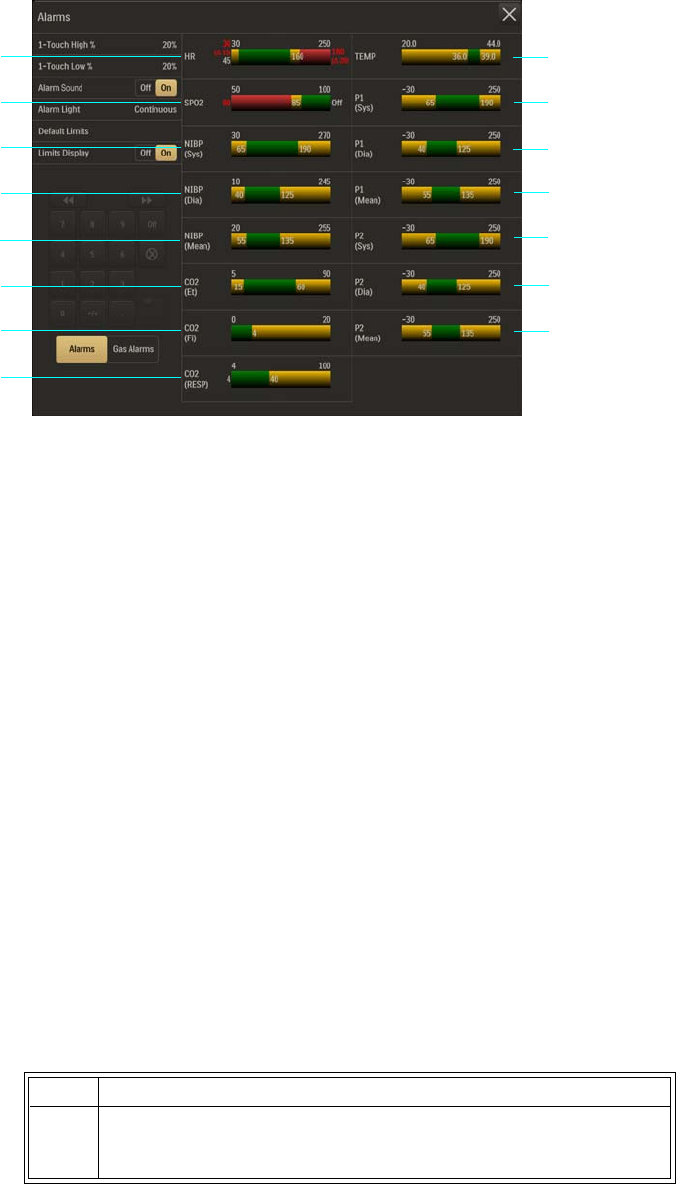
4‐14AlarmsExpressionMR400InstructionsforUse
ToadjustthealarmlimitsettingsforasingleparameterintheAlarmsmenu
1TEMP – (Temperature)
2P1 (Sys) – (P1 [Systolic])
3P1 (Dia) – (P1 [Diastolic])
4P1 (Mean)
5P2 (Sys) – (P2 [Systolic])
6P2 (Dia) – (P2 [Diastolic])
7P2 (Mean)
8CO2 (RESP) – (CO2 [Respiration])
9CO2 (Fi) – (CO2 [Fractional inspired])
10 CO2 (Et) – (CO2 [End-tidal])
11 NIBP (Mean)
12 NIBP (Dia) – (NIBP [Diastolic])
13 NIBP (Sys) – (NIBP [Systolic])
14 SPO2
15 HR – (Heart rate)
Step Action
1PresstheSetupkeyandthentheAlarmskey.
TheAlarmsmenuappears.Currentsettingsaredisplayed.
1
2
3
4
5
6
7
8
9
10
11
12
13
14
15
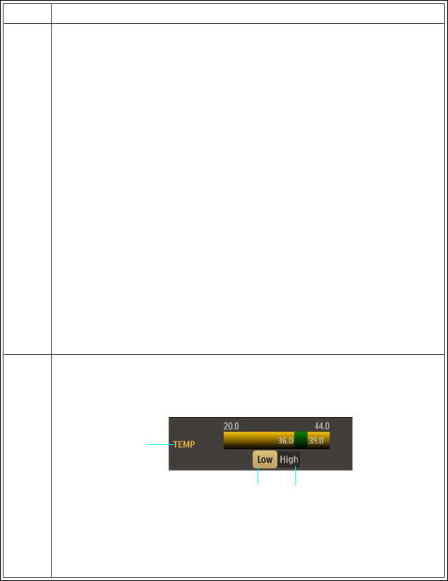
ExpressionMR400InstructionsforUseAlarms4‐15
2PressthedesiredparameterlabelontheAlarmsmenu:
HR
SPO2
NIBP(Sys)
NIBP(Dia)
NIBP(Mean)
CO2(Et)
CO2(Fi)
CO2(RESP)
TEMP
P1(Sys)
P1(Dia)
P1(Mean)
P2(Sys)
P2(Dia)
P2(Mean)
Thebackgroundoftheselectedparameterbecomeshighlighted
(TEMPinthisexample).
3 Dependinguponthealarmlimittobemodified,presstheLow
buttonortheHighbutton.
Inthisexample,theLowbuttonwasselectedtoadjustthelower
alarmlimitsetting.
Step Action
Parameter
label
Low
button
High
button
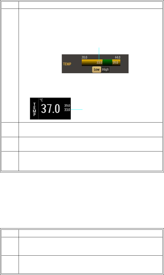
4‐16AlarmsExpressionMR400InstructionsforUse
Restoring Alarm Limit Defaults
WheneverthePatientTypesettingischanged(seepage3‐11),theMR400automaticallyrestores
thedefaultvaluestoallthealarmlimitsettings;seepage4‐24foralistingofthedefaultvalues.
Toimmediatelyrestorethealarmlimitstothedefaultsettings
4Usetheincrementorthedecrementbuttontoadjustthesetting.
Or,directlyinputthevalueusingthekeypad,theplus/minus
buttonand/orthedecimalpointbuttonthenpresstheEnter
button.(Foritemlocations,seeAlarmLimitControlsonpage4‐9.)
Thecurrentadjustmentwillreflectthesetting.(Inthisexample,the
lowerlimitsettingwasadjustedfrom36to33.)
5Tochangetheremainingsetting,repeatsteps3and4.
6Tochangeanyremainingparameters,repeatsteps2,3,and4.
7PresstheMainScreenkeytoclosethemenu.
Newlimitsettingswillbeindicatedintheparameter’sVSbox.
Step Action
Adjusted lower limit
Lower alarm limit setting
Step Action
1PresstheSetupkeyandthentheAlarmskey.
TheAlarmsmenuappears.Currentsettingsaredisplayed.
2 SelectDefaultLimits.
Thealarmlimitsettingsarereturnedtothedefaultvalues.
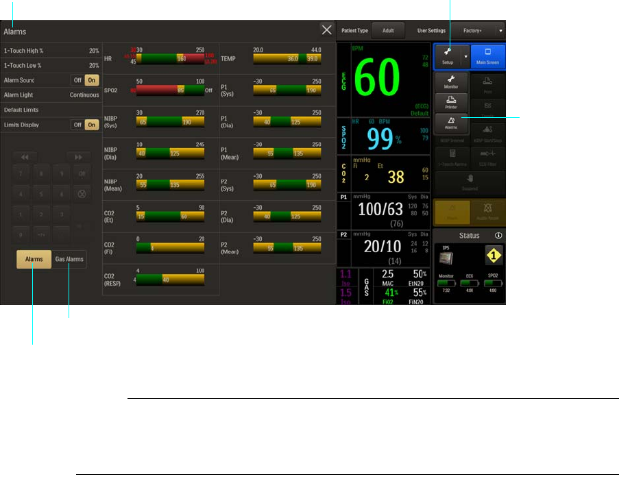
ExpressionMR400InstructionsforUseAlarms4‐17
Enabling Print on Alarm
IftheMR400isconnectedtoanIP5thatisequippedwithaprinter,aprintoutcanbe
automaticallygeneratedwhenaphysiologicalalarmoccurs.SeetheIP5IFUfordetails.
Alarms Menu
TheAlarmsmenuallowsyoutoconfiguretheMR400forsetupandcontrolofthevitalsign
alarms.
ToopentheAlarmsmenu
PresstheSetupkeyandthentheAlarmskey.
Notes
• Select the Alarms button to access the alarm limits settings for parameters.
• Select the Gas Alarms button to access the alarm limits settings for AGENT and GAS.
Alarms menu Setup key
Alarms key
Alarms button
Gas Alarms button

4‐18AlarmsExpressionMR400InstructionsforUse
ThefollowingAlarmsmenuitemsareavailable:
TochangesettingsintheAlarmsmenu
1-Touch High %
Setsapercentvalueusedtocalculatethehighalarmlimitswhenthe1‐TouchAlarmskeyis
pressed.Thecurrentparametervalueisbracketedwiththepercentagessetinthismenuandin
the1‐TouchLow%menu.
Thefollowingoptionsareavailable:
•5%
• 1-Touch High %
• 1-Touch Low %
•Alarm Sound
•Alarm Light
•Default Limits
• Limits Display
Step Action
1PresstheSetupkeyandthentheAlarmskey.
TheAlarmsmenuappears.Currentsettingsaredisplayed.
2 Selectanyofthefollowingmenuitems:
1‐TouchHigh%
1‐TouchLow%
AlarmSound
AlarmLight
DefaultLimits
LimitsDisplay
Forinformationabouttheseoptions,seetheappropriatesections
below.
3 Selectthedesiredmenuitem.
Thecurrentsettingishighlighted.
4 Selectthedesiredsettingfromthemenuoptions.
Thesettingisentered.
5Tochangeothersettings,repeatsteps2,3and4.

ExpressionMR400InstructionsforUseAlarms4‐19
•10%
•15%
•20%(Default)
•30%
Tosettheupperwindow
SeeSettingAlarmLimitsGloballyonpage4‐12.
Note
If, during calculation, a patient’s monitored value is so high that it exceeds the alarm limit range
for the parameter, then the respective alarm limit will be set to the highest value but not off, as
indicated in the table on page 4-22.
1-Touch Low %
Setsapercentvalueusedtocalculatethelowalarmlimitswhenthe1‐TouchAlarmskeyis
pressed.Thecurrentparametervalueisbracketedwiththepercentagessetinthismenuandin
the1‐TouchHigh%menu.
Thefollowingoptionsareavailable:
•5%
•10%
•15%
•20%(Default)
•30%
Tosetthelowercalculationvalue
SeeSettingAlarmLimitsGloballyonpage4‐12.
Note
If, during calculation, a patient’s monitored value is so low that it exceeds the alarm limit range
for the parameter, then the respective alarm limit will be set to lowest possible value but not off, as
indicated in the table on page 4-22.
4‐20AlarmsExpressionMR400InstructionsforUse
Alarm Sound
WARNING
The alarm sound can be turned off, as indicated by the symbol. Always ensure that the
alarm sound setting is appropriate for the monitoring environment and for each patient. The
alarm sound volume is adjustable for suitability to various clinical environments. When you
use the MR400, always ensure that the alarm sound can be heard above the ambient noise
level; otherwise, treatment of the patient could be delayed.
Controlsthealarmsound(identicaltoandinteractivewithAlarmsintheMonitorSetup>Sound
Adjustmenu).
Thefollowingoptionsareavailable:
•Offturnsoffthealarmsound,asindicatedbythealarmaudiooffsymbol(seepage4‐4).
(Onlythealarmsoundwillbedisabled;visualalarmindicationswillcontinue.)
•Onturnsonthealarmsound,asindicatedbythealarmaudioarmedsymbol(seepage4‐
4).(Default)
Tocontrolthealarmsound
Alarm Light
Setsthebehaviorofthealarmlightfollowingthedetectionofanalarm.
Thefollowingoptionsareavailable:
•Continuousilluminatesthealarmlightforthedurationofanalarmcondition.(Default)
• Temporaryilluminatesthealarmlightfor25secondsduringanalarmcondition.(Ifthe
MR400isplacedinsuspendmodeorifthealarmissilencedorpausedduringthisperiod,
thenuponexitingthealarmlightwillrestartfor25seconds.)
•Offdoesnotilluminatethealarmlightduringanalarmcondition.
Step Action
1PresstheSetupkeyandthentheAlarmskey.
TheAlarmsmenuappears.Currentsettingsaredisplayed.
2LocateAlarmSoundandselectthedesiredsetting:
Off
On
Thesettingisentered.
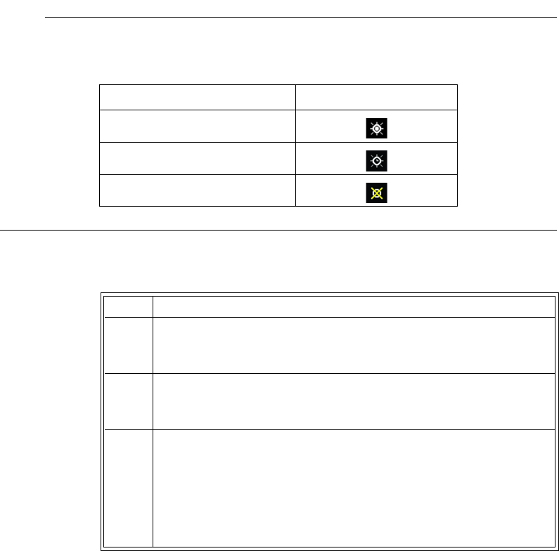
ExpressionMR400InstructionsforUseAlarms4‐21
Note
As defined in the table below, the current Alarm Light setting is indicated by the displayed symbol
on the information bar (see page 2-14).
Toadjustthealarmlightsetting
Default Limits
Automaticallysetsthelowalarmlimitsandhighalarmlimitsforallparameterstothedefault
values(seethetableonpage4‐24).
Tosetthealarmlimitsettingstothedefaultlimits
SeeRestoringAlarmLimitDefaultsonpage4‐16.
Limits Display
ControlsthevisibilityofthealarmlimitsettingsintheVSboxes.
Thefollowingoptionsareavailable:
Alarm Light Setting Displayed Symbol
Continuous
Temporary
Off
Step Action
1PresstheSetupkeyandthentheMonitorkey.
TheMonitorSetupmenuappears.Currentsettingsaredisplayed.
2OntheMonitorSetupmenu,selectAlarmLight.
TheAlarmLightmenuappears.Thecurrentsettingishighlighted.
3 Selectthedesiredsettingfromthemenuoptions:
Continuous
Temporary
Off
Thesettingisentered.

4‐22AlarmsExpressionMR400InstructionsforUse
•Offdoesnotdisplaythealarmlimitsettings.
•Ondisplaysthealarmlimitsettings.(Default)
Tocontrolthedisplayfunctionforthealarmlimitsettings
Adjustable Alarm Limit Ranges
Withtheexceptionofbellowsrespiration,eachparameteralarmhasadjustablelimitsasindicatedin
thetablesbelow
.
Notethatthealarmlimitnumericvaluescanbesettooff,withtheexceptionof
O2,N2O,FiCO2.
TheMR400alsopreventscrossoveroflowandhighalarmlimitsettings,anda
minimumnumberofunitsseparatestheselowandhighsettings.Whenaparameterhasbeen
turnedoff,itsalarmlimitswillbeoff.Alarmlimitsareadjustablebythesameresolutionspecifiedin
eachparameter'smeasurementresolutionsetforthinAppendixA.
Note
The minimum and maximum values for the low and high limits represent the most extreme settings
possible. For some vital signs, these values can be obtained for a low or high alarm limit only if
the other limit is off.
ThetablebelowprovidesthealarmlimitrangesfortheMR400.
Step Action
1PresstheSetupkeyandthentheAlarmskey.
TheAlarmsmenuappears.Currentsettingsaredisplayed.
2 SelectLimitsDisplay.
TheLimitsDisplaymenuappears.Thecurrentsettingis
highlighted.
3 Selectthedesiredoptionfordisplayofthealarmlimitsettings:
Off
On
Thesettingisselected.
Vital Sign or
Parameter Unit Patient Type
Low Alarm Limit*High Alarm Limit*Low and
High Limit
Separation
Minimum Maximum Minimum Maximum
HR BPM All Off, 30 250 60 250, Off 2
SPO2 Percent All Off, 50 100 70 100, Off 2
CO2 (Et) mmHg
kPa
All Off, 5
Off, 0.7
60
8.0
5
0.7
90, Off
12.0, Off
2

ExpressionMR400InstructionsforUseAlarms4‐23
*ForallalarmlimitvaluesthatmaybedisplayedinunitsofkPa,allow+/‐0.1kPaofvariancetoaccountforroundingerrorthatmay
occurwhenconvertingfrommmHgtokPa.
Thefollowingtableprovidesthealarmlimitrangesfortheanestheticagentgasesandoxygenfor
allpatienttypes.
CO2 (Fi) mmHg
kPa
All No low alarm 0 20, Off
2.7, Off
2
CO2 (Resp) RPM All Off, 4 40 20 100, Off 2
P1 and P2 mmHg
kPa
All Off, -30
Off, -4.0
250
33.3
-30
-4.0
250, Off
33.3, Off
2
Temperature °C
°F
All Off, 20.0
Off, 68.0
44.0
111.2
20.0
68.0
44.0, Off
111.2, Off
1
NIBP — Systolic mmHg
kPa
Adult Off, 30
Off, 4.0
270
36.0
30
4.0
270, Off
36.0, Off
2
— Mean mmHg
kPa
Adult Off, 20
Off, 2.7
255
34.0
20
2.7
255, Off
34.0, Off
2
— Diastolic mmHg
kPa
Adult Off, 10
Off, 1.3
245
32.7
10
1.3
245, Off
32.7, Off
2
NIBP — Systolic mmHg
kPa
Pediatric Off, 30
Off, 4.0
180
24.0
30
4.0
180, Off
24.0, Off
2
— Mean mmHg
kPa
Pediatric Off, 20
Off, 2.7
160
21.3
20
2.7
160, Off
21.3, Off
2
— Diastolic mmHg
kPa
Pediatric Off, 10
Off, 1.3
150
20.0
10
1.3
150, Off
20.0, Off
2
NIBP — Systolic mmHg
kPa
Neo Off, 30
Off, 4.0
130
17.3
30
4.0
130, Off
17.3, Off 2
— Mean mmHg
kPa
Neo Off, 20
Off, 2.7
120
16.0
20
2.7
120, Off
16.0, Off 2
— Diastolic mmHg
kPa
Neo Off, 10
Off, 1.3
100
13.3
10
1.3
100, Off
13.3, Off 2
Vital Sign or
Parameter Unit Patient Type
Low Alarm Limit*High Alarm Limit*Low and
High Limit
Separation
Minimum Maximum Minimum Maximum
Breath Phase and Gas Unit
Low Alarm Limit High Alarm Limit Low and
High Limit
Separation
Minimum Maximum Minimum Maximum
DES (Et), Expired Desflurane Vol. % Off, 0.1 18.0 0.1 18.0, Off 1
DES (Fi), Inspired Desflurane Vol. % Off, 0.1 18.0 0.1 18.0, Off 1
ENF (Et) Expired Enflurane Vol. % Off, 0.1 5.0 0.1 5.0, Off 1
ENF (Fi) Inspired Enflurane Vol. % Off, 0.1 5.0 0.1 5.0, Off 1
HAL (Et) Expired Halothane Vol. % Off, 0.1 5.0 0.1 5.0, Off 1
HAL (Fi) Inspired Halothane Vol. % Off, 0.1 5.0 0.1 5.0, Off 1
ISO (Et) Expired Isoflurane Vol. % Off, 0.1 5.0 0.1 5.0, Off 1
ISO (Fi) Inspired Isoflurane Vol. % Off, 0.1 5.0 0.1 5.0, Off 1

4‐24AlarmsExpressionMR400InstructionsforUse
Alarm Limit Factory Defaults
Intheeventofpowerloss,anyalarmlimitsettingsthatwerechangedwillbelost.Allsettingsthat
mayhavebeenmodifiedtosuitaparticularpatientshouldbeconfirmedbeforemonitoring.
Atpowerup,theMR400willautomaticallysetallalarmlimitsasdeterminedbythedefault
selectedintheEditUserSettingsmenu;seepage3‐15.Thefactorydefaultalarmlimitsarelisted
inthetablebelow.
Note
You are restricted from making changes to the factory default settings.
SEV (Et) Expired Sevoflurane Vol. % Off, 0.1 8.0 0.1 8.0, Off 1
SEV (Fi) Inspired Sevoflurane Vol. % Off, 0.1 8.0 0.1 8.0, Off 1
N2O (Fi) Inspired Nitrous
Oxide Percent No low alarm 0 80 1
O2 (Fi) Inspired Oxygen Percent 18 100 18 100 1
Breath Phase and Gas Unit
Low Alarm Limit High Alarm Limit Low and
High Limit
Separation
Minimum Maximum Minimum Maximum
Vital Sign or Parameter Unit
Adult Pediatric Neo
Low
Limit
High
Limit
Low
Limit
High
Limit
Low
Limit
High
Limit
Heart Rate BPM 45 160 75 160 90 210
Heart Rate - Extreme
Bradycardia
BPM202020202020
Heart Rate - Extreme
Tachycardia
BPM202020202020
SPO2 Percent 85 Off 90 Off 90 Off
SPO2 - Desat Percent 80 80 80 80 80 80
CO2 (Et) mmHg
kPa
15
2.0
60
8.0
15
2.0
60
8.0
30
4.0
45
6.0
CO2 (Fi) mmHg
kPa
No low
alarm
4
0.5
No low
alarm
4
0.5
No low
alarm
4
0.5
CO2 (Resp) RPM 4 40 4 40 30 70
P1 / P2 Systolic mmHg
kPa
65
8.7
190
25.3
70
9.3
120
16.0
70
9.3
100
13.3
P1 / P2 Mean mmHg
kPa
55
7.3
135
18.0
50
6.7
90
12.0
40
5.3
90
12.0
P1 / P2 Diastolic mmHg
kPa
40
5.3
125
16.7
40
5.3
70
9.3
35
4.7
50
6.7

ExpressionMR400InstructionsforUseAlarms4‐25
*ForallalarmlimitvaluesthatmaybedisplayedinunitsofkPa,allow+/‐0.1kPaofvariancetoaccountforroundingerrorthatmay
occurwhenconvertingfrommmHgtokPa.
Measurement Limits and Over / Under Values
Inthetablebelow,therangeofvaluesthatcanbemeasuredforavitalsignitemareprovided
alongwiththehighandlowvaluesthat,beyondwhich,anoverorunderindicationwillbegiven.
Specifically,avaluewillbemarkedasOver(OVR)iftheVSvalueisgreaterthanthegivenover
value,andmarkedasUnder(UND)iftheVSvalueislessthanthegivenundervalue.
NIBP Systolic mmHg
kPa
65
8.7
190
25.3
70
9.3
120
16.0
70
9.3
100
13.3
NIBP Mean mmHg
kPa
55
7.3
135
18.0
50
6.7
90
12.0
40
5.3
90
12.0
NIBP Diastolic mmHg
kPa
40
5.3
125
16.7
40
5.3
70
9.3
35
4.7
50
6.7
Temperature °C
°F
36.0
96.8
39.0
102.2
36.0
96.8
39.0
102.2
36.0
96.8
39.0
102.2
DES (Et), Expired Desflurane Vol. % Off 12.0 Off 12.0 Off 12.0
DES (Fi), Inspired Desflurane Vol. % Off 18.0 Off 18.0 Off 18.0
ENF (Et) Expired Enflurane Vol. % Off 3.4 Off 3.4 Off 3.4
ENF (Fi) Inspired Enflurane Vol. % Off 5.0 Off 5.0 Off 5.0
HAL (Et) Expired Halothane Vol. % Off 1.5 Off 1.5 Off 1.5
HAL (Fi) Inspired Halothane Vol. % Off 2.2 Off 2.2 Off 2.2
ISO (Et) Expired Isoflurane Vol. % Off 2.3 Off 2.3 Off 2.3
ISO (Fi) Inspired Isoflurane Vol. % Off 3.4 Off 3.4 Off 3.4
SEV (Et) Expired Sevoflurane Vol. % Off 4.1 Off 4.1 Off 4.1
SEV (Fi) Inspired Sevoflurane Vol. % Off 6.1 Off 6.1 Off 6.1
N2O (Fi) Inspired Nitrous
Oxide
Percent No low
alarm 80 No low
alarm 80 No low
alarm 80
O2 (Fi) Inspired OxygenPercent189918991899
Vital Sign or Parameter Unit
Adult Pediatric Neo
Low
Limit
High
Limit
Low
Limit
High
Limit
Low
Limit
High
Limit
Vital Sign or
Parameter
Numeric
Item Units Patient
Type
Measurement
Range
Over / Under
Values
Low High Under Over
ECG Heart Rate BPM Adult 30 250 30 250
ECG Heart Rate BPM Ped 30 300 30 300
ECG Heart Rate BPM Neo 30 300 30 300
SPO2 Heart Rate BPM All 30 250 30 250

4‐26AlarmsExpressionMR400InstructionsforUse
Listing of Alarms
Thissectionlistspatientalarmsalphabetically,andtechnicalalarms(INOPs)arrangedbythe
sourceoftheINOPandthenalphabetically,irrespectiveofpriority.AllalarmsandINOPsare
listedhere;thosewhichcanappearonyourMR400willdependontheinstalledoptions.
SPO2 Saturation % All 1 100 none none
P1 and P2 Systolic mmHg Adult -30 250 -30 250
P1 and P2 Mean mmHg Ped -30 250 -30 250
P1 and P2 Diastolic mmHg Neo -30 250 -30 250
P1 and P2 Pulse Rate BPM All 30 250 30 250
NIBP Systolic mmHg Adult 30 270 30 270
NIBP Systolic mmHg Ped 30 180 30 180
NIBP Systolic mmHg Neo 30 130 30 130
NIBP Mean mmHg Adult 20 255 20 255
NIBP Mean mmHg Ped 20 160 20 160
NIBP Mean mmHg Neo 20 120 20 120
NIBP Diastolic mmHg Adult 10 245 10 245
NIBP Diastolic mmHg Ped 10 150 10 150
NIBP Diastolic mmHg Neo 10 100 10 100
Temperature Temperature °C All 20.0 44.0 20.0 44.0
CO2 (LoFlo option) CO2 (Et) mmHg All 0 90 none 90
CO2 (LoFlo option) CO2 (Fi) mmHg All 0 90 none 90
CO2 (LoFlo option) Resp. Rate RPM All 4 100 none 100
CO2 (AGENT option) CO2 (Et) mmHg All 0 90 none 90
CO2 (AGENT option) CO2 (Fi) mmHg All 0 90 none 90
CO2 (AGENT option) Resp. Rate RPM All 4 100 4 100
AGENT Desflurane (Et & Fi) % All 0 18.0 none 18.0
AGENT Enflurane (Et & Fi) % All 0 5.0 none 5.0
AGENT Halothane (Et & Fi) % All 0 5.0 none 5.0
AGENT Isoflurane (Et & Fi) % All 0 5.0 none 5.0
AGENT Sevoflurane (Et & Fi) % All 0 8.0 none 8.0
AGENT N2O (Et) % All 0 100 none none
AGENT N2O (Fi) % All 0 100 none none
AGENT O2 (Fi) % All 0 100 none none
Bellows Respiration Resp. Rate RPM All 4 150 4 150
Vital Sign or
Parameter
Numeric
Item Units Patient
Type
Measurement
Range
Over / Under
Values
Low High Under Over

ExpressionMR400InstructionsforUseAlarms4‐27
VitalSignValueState
Avitalsignvalueisconsideredmissing(asindicatedbythreedashes,‐‐‐)whenthevitalsignhas
producedavaluesincethemonitorwasturnedon,butcannolongerproduceavalue.Examples
ofthevaluesthatcouldbecomemissingduringnormaluse,include:
•ECGheartratevalueiftheleadsareremoved.
•SPO2valueduringNoProbe,ProbeOff,etcetera.
• Temperaturevalueiftheprobewasremoved.
•Invasivepressurevaluesifthetransducerisremoved.
WhenavaluebecomesmissingduetoanINOP,anINOPalarmwillbepresent.And,apatient
alarm—duetothemissingvalue—willbepresentaswell.Therefore,thesystemcanhavean
INOPalarm,andapatientalarm,activeatthesametimeandfromthesamecause.
WARNING
If, during use, an alarm condition listed below results in a loss of patient monitoring
capability, employ an alternate means as needed to prevent a lapse in patient monitoring;
otherwise, treatment of the patient could be delayed.
Patient and INOP Alarms
Themeasurementlabelsandabbreviationsforpressure,temperature,SpO2,CO2andanesthetic
agentalarmsareexplainedintheindividualchapters.Thefollowingtablecontainsalistingof
patientalarmsarrangedbyvitalsignorparameter.Theparametermustbeonfortherespective
alarmdetectionstobeenabled;seepage3‐18.
Note
In the case of missing data (- - -), an alarm will occur only if a valid numeric was previously displayed but can
no longer be produced; see page 2-20 for details.
Patient Alarm From Condition Indication
Extreme Brady ECG, SPO2, P1
(or P2)
The heart rate measurement has
violated the Extreme Bradycardia
alarm setting.
Red flag in ECG alarm flag area, flashing red
heart rate numeric in the ECG VS box and in
the SPO2 VS box, red alarm light, high priority
alarm tone
Extreme Tachy ECG, SPO2, P1
(or P2)
The heart rate measurement has
violated the Extreme Tachycardia
alarm setting.
Red flag in ECG alarm flag area, flashing red
heart rate numeric in the ECG VS box and in
the SPO2 VS box, red alarm light, high priority
alarm tone
Violated heart rate
value
ECG, SPO2, P1
(or P2)
The heart rate measurement has
violated an alarm limit setting.
Flashing yellow heart rate numeric in the ECG
VS box and in the SPO2 VS box, yellow alarm
light, medium priority alarm tone

4‐28AlarmsExpressionMR400InstructionsforUse
Missing heart rate data ECG, SPO2, P1
(or P2)
The heart rate data, once present,
can no longer be produced.
Flashing yellow dashes (- - -) in the heart rate
numeric in the ECG VS box and in the SPO2
VS box, yellow alarm light, medium priority
alarm tone
Over maximum heart
rate value
ECG, SPO2, P1
(or P2)
The heart rate measurement has
violated the upper parameter
range.
Flashing red heart rate numeric alternating
between OVR and the heart rate value in the
ECG VS box and in the SPO2 VS box, red alarm
light, high priority alarm tone
Under minimum heart
rate value
ECG, SPO2, P1
(or P2)
The heart rate measurement has
violated the lower parameter
range.
Flashing red heart rate numeric alternating
between UND and the heart rate value in the
ECG VS box and in the SPO2 VS box, red alarm
light, high priority alarm tone
Desat SPO2 SPO2 has detected a desaturation
event.
Red flag in ECG alarm flag area, flashing red
SpO2 numeric, red alarm light, high priority
alarm tone
Violated arterial oxygen
saturation value
SPO2 The arterial oxygen saturation
measurement has violated an
alarm limit setting.
Flashing yellow SpO2 numeric in the SPO2 VS
box, yellow alarm light, medium priority alarm
tone
Missing arterial oxygen
saturation data
SPO2 The arterial oxygen saturation
data, once present, can no longer
be produced.
Flashing yellow dashes (- - -) in the SpO2
numeric in the SPO2 VS box, yellow alarm
light, medium priority alarm tone
Apnea CO2, AGENT The apnea time delay setting has
been exceeded.
Red flag in the CO2 or RESP alarm flag area,
Flashing red respiration rate numeric, red
alarm light, high priority alarm tone
Note
Apnea alarm flag appears in either the CO2 or
the RESP alarm flag area, based on the RESP
source.
Violated EtCO2 value CO2, AGENT The end-tidal CO2 measurement
has violated an alarm limit setting.
Flashing yellow EtCO2 numeric in the CO2 VS
box, yellow alarm light, medium priority alarm
tone, where OVR displayed if the value is
greater than the highest specified
Missing EtCO2 data CO2, AGENT The end-tidal CO2 data, once
present, can no longer be
produced.
Flashing yellow dashes (- - -) in the EtCO2
numeric in the CO2 VS box, yellow alarm light,
medium priority alarm tone
Violated FiCO2 value CO2, AGENT The fractional inspired CO2
measurement has violated an
alarm limit setting.
Flashing yellow FiCO2 numeric in the CO2 VS
box, yellow alarm light, medium priority alarm
tone, where OVR displayed if the value is
greater than the highest specified
Missing FiCO2 data CO2, AGENT The fractional inspired CO2 data,
once present, can no longer be
produced.
Flashing yellow dashes (- - -) in the FiCO2
numeric in the CO2 VS box, yellow alarm light,
medium priority alarm tone
Patient Alarm From Condition Indication

ExpressionMR400InstructionsforUseAlarms4‐29
Violated CO2
respiration rate value
CO2, AGENT The CO2 respiration rate
measurement has violated an
alarm limit setting.
Depending upon RESP VS box configuration:
• Flashing yellow respiration rate numeric
in the CO2 VS box, yellow alarm light,
medium priority alarm tone, or
• Flashing yellow respiration rate numeric
in the RESP VS box, yellow alarm light,
medium priority alarm tone
• And where OVR displayed if the value is
greater than the highest specified
• And where UND if the value is less than
the lowest specified (AGENT option
only)
Missing CO2 respiration
rate data
CO2, AGENT The CO2 respiration rate data,
once present, can no longer be
produced.
Depending upon RESP VS box configuration:
• Flashing yellow dashes (- - -) in the
respiration rate numeric in the CO2 VS
box, yellow alarm light, medium priority
alarm tone, or
• Flashing yellow dashes (- - -) in the
respiration rate numeric in the RESP VS
box, yellow alarm light, medium priority
alarm tone
Violated invasive blood
pressure systolic value
P1 (and P2) The P1 (or P2) invasive blood
pressure systolic measurement has
violated an alarm limit setting.
Flashing yellow systolic numeric in the P1 VS
box, yellow alarm light, medium priority alarm
tone, where OVR displayed if the value is
greater than the highest specified or UND if
the value is less than the lowest specified
Violated invasive blood
pressure mean value
P1 (and P2) The P1 (or P2) invasive blood
pressure mean measurement has
violated an alarm limit setting.
Flashing yellow mean numeric in the P1 VS
box, yellow alarm light, medium priority alarm
tone, where OVR displayed if the value is
greater than the highest specified or UND if
the value is less than the lowest specified
Violated invasive blood
pressure diastolic value
P1 (and P2) The P1 (or P2) invasive blood
pressure diastolic measurement
has violated an alarm limit setting.
Flashing yellow diastolic numeric in the P1 VS
box, yellow alarm light, medium priority alarm
tone, where OVR displayed if the value is
greater than the highest specified or UND if
the value is less than the lowest specified
Missing invasive blood
pressure data
P1 (and P2) The P1 (or P2) invasive blood
pressure data, once present, can
no longer be produced.
Flashing yellow dashes (- - -) in the systolic,
diastolic and mean numerics in the P1 VS box,
yellow alarm light, medium priority alarm tone
Violated primary agent
Et value
AGENT The end-tidal measurement for the
primary agent gas has violated an
alarm limit setting.
Flashing yellow primary agent Et numeric in the
AGENT VS box, yellow alarm light, medium
priority alarm tone, where OVR displayed if
the value is greater than the highest specified
Violated primary agent
Fi value
AGENT The fractional inspired
measurement for the primary
agent gas has violated an alarm
limit setting.
Flashing yellow primary agent Fi numeric in the
AGENT VS box, yellow alarm light, medium
priority alarm tone, where OVR displayed if
the value is greater than the highest specified
Patient Alarm From Condition Indication

4‐30AlarmsExpressionMR400InstructionsforUse
Violated secondary
agent Et value
AGENT The end-tidal measurement for the
secondary agent gas has violated
an alarm limit setting.
Flashing yellow secondary agent Et numeric in
the AGENT VS box, yellow alarm light,
medium priority alarm tone, where OVR
displayed if the value is greater than the highest
specified
Violated secondary
agent Fi value
AGENT The fractional inspired
measurement for the secondary
agent gas has violated an alarm
limit setting.
Flashing yellow secondary agent Fi numeric in
the AGENT VS box, yellow alarm light,
medium priority alarm tone, where OVR
displayed if the value is greater than the highest
specified
Missing primary and
secondary agent data
AGENT The primary and secondary agent
data, once present, can no longer
be produced.
Flashing yellow dashes (- - -) in the primary and
secondary numerics in the AGENT VS box,
yellow alarm light, medium priority alarm tone
Violated N2O value AGENT The N2O measurement has
violated an alarm limit setting.
Flashing yellow N2O numeric in the GAS VS
box, yellow alarm light, medium priority alarm
tone
Missing N2O data AGENT The N2O data, once present, can
no longer be produced.
Flashing yellow dashes (- - -) in the N2O
numeric in the GAS VS box, yellow alarm light,
medium priority alarm tone
Violated O2 value AGENT The O2 measurement has violated
an alarm limit setting.
Flashing yellow O2 numeric in the GAS VS
box, yellow alarm light, medium priority alarm
tone
Violated O2 value AGENT The O2 measurement is less than
18 percent.
Flashing red O2 numeric in the GAS VS box,
red alarm light, high priority alarm tone
Missing O2 data AGENT The O2 data, once present, can no
longer be produced.
Flashing yellow dashes (- - -) in the O2 numeric
in the GAS VS box, yellow alarm light, medium
priority alarm tone
Missing bellows
respiration rate data
RESP The bellows respiration data, once
present, can no longer be
produced.
Flashing yellow dashes (- - -) in the respiration
rate numeric in the RESP VS box, yellow alarm
light, medium priority alarm tone
Violated temperature
value
TEMP The temperature measurement
has violated an alarm limit setting.
Flashing yellow temperature numeric in the
TEMP VS box, yellow alarm light, medium
priority alarm tone, where OVR displayed if
the value is greater than the highest specified
or UND if the value is less than the lowest
specified
Missing temperature
data
TEMP The temperature data, once
present, can no longer be
produced.
Flashing yellow dashes (- - -) in the
temperature numeric in the TEMP VS box,
yellow alarm light, medium priority alarm tone,
where OVR displayed if the value is greater
than the highest specified or UND if the value
is less than the lowest specified
Violated non-invasive
blood pressure systolic
value
NIBP The non-invasive blood pressure
systolic measurement has violated
an alarm limit setting.
Flashing yellow systolic numeric in the NIBP VS
box, yellow alarm light, medium priority alarm
tone, where OVR displayed if the value is
greater than the highest specified or UND if
the value is less than the lowest specified
Patient Alarm From Condition Indication

ExpressionMR400InstructionsforUseAlarms4‐31
Technical (INOP) Alarms and Other Status Flags
ThefollowingtablecontainsalistingoftheINOPandotherstatusalarmflagmessages,locations,
toneindications,andwhereapplicablepossiblesolutions.
ECG
Violated non-invasive
blood pressure mean
value
NIBP The non-invasive blood pressure
mean measurement has violated an
alarm limit setting.
Flashing yellow mean numeric in the NIBP VS
box, yellow alarm light, medium priority alarm
tone, where OVR displayed if the value is
greater than the highest specified or UND if
the value is less than the lowest specified
Violated non-invasive
blood pressure diastolic
value
NIBP The non-invasive blood pressure
diastolic measurement has violated
an alarm limit setting.
Flashing yellow diastolic numeric in the NIBP
VS box, yellow alarm light, medium priority
alarm tone, where OVR displayed if the value
is greater than the highest specified or UND if
the value is less than the lowest specified
Missing non-invasive
blood pressure data
NIBP The non-invasive blood pressure
data, once present, can no longer
be produced.
Flashing yellow dashes (- - -) in the systolic,
diastolic and mean numerics in the NIBP VS
box, yellow alarm light, medium priority alarm
tone
Patient Alarm From Condition Indication
Message, Location,
Indication
What to Do
Lead Fail
ECG alarm flag area, blue
alarm light, INOP alarm
tone
An ECG lead (or electrode) required to measure the lead view is faulty or disconnected:
• Ensure that the ECG lead cable is connected to the wECG module, and that the wECG module
has sufficient battery power.
• Ensure that each ECG lead cable clip is connected to the Quadtrode electrode contact.
(Examine the ECG VS box for indications of a contact problem, where LL = left leg, LA = left
arm, and RA = right arm, and LL, LA, RA, = RL [right leg] or all leads.)
• Replace the ECG lead cable.
• Replace the Quadtrode electrode.
Notes
• The error message can be displayed for trace A and/or for trace B.
• May also be displayed when high DC offsets are present on an input lead.

4‐32AlarmsExpressionMR400InstructionsforUse
SPO2
Lead Saturation
ECG alarm flag area, blue
alarm light, INOP alarm
tone
Baseline offset of the ECG input signal is too large for process and display of the waveform. Replace
the Quadtrode electrode.
Note
The error message can be displayed for trace A and/or for trace B.
Message, Location,
Indication
What to Do
Bad Probe
SPO2 alarm flag area, blue
alarm light, INOP alarm
tone
The SpO2 probe is defective. Replace the SpO2 probe.
Erratic
SPO2 alarm flag area, blue
alarm light, INOP alarm
tone
The SpO2 attachment may be improperly applied or positioned on the patient; or, the probe is
faulty.
• Check the alignment of the clip (or grip) on the patient.
• Replace the SpO2 probe.
If the message persists, contact technical support or authorized service personnel.
HW Fail
SPO2 alarm flag area, blue
alarm light, INOP alarm
tone
A hardware or other failure has occurred in the wSpO2 module. Replace the wSpO2 module.
If the failure persists, immediately remove the MR400 and the wSpO2 module from service then
contact technical support or authorized service personnel, as the system must not be used on any
patient requiring SpO2 measurement.
Intrfernce
SPO2 alarm flag area, blue
alarm light, INOP alarm
tone
Interference due to attachment misalignment or incorrect attachment positioning:
• Check the alignment of the clip (or grip) on the patient site.
• Try a different limb or site.
• Ensure that the module is placed outside of the MR bore.
• Reposition the wSpO2 module (see page 6-6.
• Replace the clip (or grip).
Low Perf
SPO2 alarm flag area, blue
alarm light, INOP alarm
tone
Accuracy may be compromised due to low perfusion. The tissue at the SpO2 attachment site may
be too opaque, thick or cold.
• If the clip (or grip) is positioned on a finger, check for long, artificial or polished nails. Remove
any nail polish or relocate the attachment if needed.
• Try another attachment site, like a toe.
• Try rubbing or warming the limb to stimulate circulation.
No Probe
SPO2 alarm flag area, blue
alarm light, INOP alarm
tone
The SpO2 probe is not attached or is improperly attached to the wSpO2 module. Check the
connection of the probe to the module. Reconnect the probe or, if the connection was good,
replace the probe.
Message, Location,
Indication
What to Do

ExpressionMR400InstructionsforUseAlarms4‐33
CO2 / CO (RESP) / AGENT
Noise
SPO2 alarm flag area, blue
alarm light, INOP alarm
tone
Excessive patient motion, the MRI scan sequence or electrical interference is causing noise in the
SpO2 system:
• Stop any patient motion, especially at the monitored site.
• Ensure that the module is placed outside of the MR bore.
• Ensure the clip (or grip) is positioned in a way that does not expose it to bright ambient light.
Non-Pulsat
SPO2 alarm flag area, blue
alarm light, INOP alarm
tone
The detected pulse is too weak for reliable reporting of SpO2 measurements:
• Check the patient’s condition.
• Check the clip (or grip) position and alignment on the patient then re-position or re-apply as
necessary.
• Try a different limb or site.
Probe Off
SPO2 alarm flag area, blue
alarm light, INOP alarm
tone
The SpO2 attachment is not properly applied to the patient. Reposition the clip (or grip) on the
patient.
Pulse?
SPO2 alarm flag area, blue
alarm light, INOP alarm
tone
Pulse reading is questionable. The SpO2 attachment may not be applied optimally or the tissue at
the application site may be too opaque:
• Check the alignment of the clip (or grip) on the patient.
• Try a different limb or site.
Searching
SPO2 alarm flag area, blue
alarm light, INOP alarm
tone
The SpO2 attachment was just applied or it has shifted position on the patient:
• If the clip (or grip) was just applied, allow about 20 seconds for the system to lock on to a good
pulse.
• Check the clip (or grip) position and reposition it if necessary.
• Replace the SpO2 probe.
If the message persists, contact technical support or authorized service personnel.
Wrong Prb
SPO2 alarm flag area, blue
alarm light, INOP alarm
tone
The probe attached to the wSpO2 module is not the correct type. Attach the correct probe to the
module.
Message, Location,
Indication
What to Do
Check CO2 Sampling
Line
CO2 alarm flag area, blue
alarm light, INOP alarm tone
Reduced flow has been detected by the CO2 system. Check the sampling line for pinches or
obstructions then clear any pinch or replace if necessary.
CO2 Cal Fail
CO2 alarm flag area, blue
alarm light, INOP alarm tone
CO2 failed to calibrate. Retry calibration.
If the message persists, contact technical support or authorized service personnel.
Message, Location,
Indication
What to Do

4‐34AlarmsExpressionMR400InstructionsforUse
CO2 Low Flow
CO2 alarm flag area, blue
alarm light, INOP alarm tone
Message may appear when the sampling line is initially connected; allow the a few seconds for the
flow to be established. Otherwise, the detected flow rate is 10 percent less than nominal; in this
case, check the sampling line for pinches or obstructions then clear any pinch or replace if
necessary.
If the message persists, contact technical support or authorized service personnel.
Check for CO2 Occlusion
CO2 alarm flag area, blue
alarm light, INOP alarm tone
Detected flow through the sampling line is less than 40 ml/min or the water trap may be full of
fluid:
• Check the sampling line for obstructions and replace it if necessary.
• Check the fluid level in the water trap and replace it if necessary.
If the message persists, contact technical support or authorized service personnel.
CO2 Out Of Range
CO2 alarm flag area, blue
alarm light, INOP alarm tone
The calculation value is greater than the upper CO2 limit. Perform readings to confirm patient’s
physiological condition.
If the message persists, contact technical support or authorized service personnel.
CO2 Sensor Faulty
CO2 alarm flag area, blue
alarm light, INOP alarm tone
CO2 bench detected a hardware or sensor error. Cycle AC mains power.
If the message persists, contact technical support or authorized service personnel.
CO2 Sensor Over Temp
CO2 alarm flag area, blue
alarm light, INOP alarm tone
The CO2 sensor is above the specified operating temperature. Confirm that the MR400 is
operating within the required environmental conditions (see Appendix A); if outside the specified
range, move the MR400 to an area that is within limits.
If the problem persists, stop all monitoring activities and contact technical support or authorized
service personnel.
CO2 Warming Up
CO2 alarm flag area, blue
alarm light, INOP alarm tone
CO2 is warming to operating temperature. Allow the process to complete, about 2 minutes.
CO2 Zero Required
CO2 alarm flag area, blue
alarm light, INOP alarm tone
Zero calibration of the CO2 module is needed; see page 7-15 for details.
Magnetic Field Too High
CO2 alarm flag area, blue
alarm light, INOP alarm tone
The gauss limit has been exceeded, and the AGENT option can no longer function. Position the
MR400 per the product labeling; see page 3-2.
HW Fail
CO2 alarm flag area, blue
alarm light, INOP alarm tone
CO2 module was not found during initialization. Cycle AC mains power.
If the message persists, contact technical support or authorized service personnel.
Low O2
AGENT alarm flag area, blue
alarm light, INOP alarm tone
The inspired O2 value has dropped below 18.0
Motor Speed Error
CO2 alarm flag area, blue
alarm light, INOP alarm
tone
The MR400 is too close to the MR magnet.
Ensure that the MR400 has been positioned correctly; see page 3-2. If the message persists, contact
technical support or authorized service personnel.
Message, Location,
Indication
What to Do

ExpressionMR400InstructionsforUseAlarms4‐35
P1 (or P2)
Multiple Agents
AGENT alarm flag area, blue
alarm light, INOP alarm tone
More than one anesthetic agent gas was detected in a given breath phase, with a total MAC of the
detected mix is less than 3 MAC.
Note
If multiple agents have been detected with a total MAC of the detected mix greater than 3 MAC then
this message will be accompanied by a yellow alarm light and medium priority alarm tone.
O2 Sensor Not Present
AGENT alarm flag area, blue
alarm light, INOP alarm tone
Possible hardware failure associated with the O2 sensor. Ensure that the O2 sensor is secure in the
receptacle; see page 14-13.
If the message persists, contact technical support or authorized service personnel.
Occlusion
CO2 alarm flag area, blue
alarm light, INOP alarm tone
Occluded sample line detected at start up:
• Check the sampling line for obstructions and replace it if necessary.
• Check the fluid level in the water trap and replace it if necessary.
If the message persists, contact technical support or authorized service personnel.
O2 Sensor Fail
CO2 alarm flag area, blue
alarm light, INOP alarm
tone
O2 sensor has failed or expired. Replace the O2 sensor; see page 14-13.
If the message persists, contact technical support or authorized service personnel.
Occlusion at Start
CO2 alarm flag area, blue
alarm light, INOP alarm tone
Occluded sample line detected at start up:
• Check the sampling line for obstructions and replace it if necessary.
• Check the fluid level in the water trap and replace it if necessary.
If the message persists, contact technical support or authorized service personnel.
Performing CO2 Zero
CO2 alarm flag area, blue
alarm light, INOP alarm tone
Displayed while zeroing CO2. Allow the process to complete.
Persistent CO2 Occlusion
CO2 alarm flag area, blue
alarm light, INOP alarm tone
Reduced CO2 flow has been detected for over 2 minutes. Check for pinches or obstructions in the
sampling line. Clear any pinch, or replace the accessory if necessary.
If the message persists, contact technical support or authorized service personnel.
Message, Location,
Indication
What to Do
Catheter Disconnected
P1 (or P2) alarm flag area,
yellow alarm light, medium
priority alarm tone
The catheter cannot be detected. Check all catheter connections to and from the transducer.
Hardware Error
P1 (or P2) alarm flag area,
blue alarm light, INOP alarm
tone
A hardware error has been detected in the IBP system. Contact technical support or authorized
service personnel.
Message, Location,
Indication
What to Do

4‐36AlarmsExpressionMR400InstructionsforUse
TEMP
Transducer Faulty
P1 (or P2) alarm flag area,
yellow alarm light, medium
priority alarm tone
A electrical transducer malfunction has been detected.
• Check the transducer cable connection.
• Replace the transducer.
• Contact technical support or authorized service personnel if the message persists.
Transducer Not Present
P1 (or P2) alarm flag area,
yellow alarm light, medium
priority alarm tone
An IBP transducer was not found. Ensure that the transducer cables are connected to the
transducer and MR400.
If the message persists, contact technical support or authorized service personnel.
Message, Location,
Indication
What to Do
Cal Error
TEMP alarm flag area, blue
alarm light, INOP alarm
tone
Calibration error. Reconnect the sensor and then retry. Contact technical support or authorized
service personnel if the message persists.
Chk Probe
TEMP alarm flag area, blue
alarm light, INOP alarm
tone
The temperature sensor connection is bad, has a sharp bend, or is damaged:
• Ensure that the sensor is inserted completely in the temperature port on the patient
connection panel.
• Remove any sharp bends in the temperature sensor.
• If the message persists after performing the above actions, then the temperature sensor
most likely is damaged and readings cannot be provided. Try a new sensor.
Exp Probe
TEMP alarm flag area, blue
alarm light, INOP alarm
tone
The temperature probe connected to the MR400 is not the proper type. Insert the correct type of
temperature probe into the temperature port.
HW Fail
TEMP alarm flag area, blue
alarm light, INOP alarm
tone
Temperature hardware failure detected. Contact technical support or authorized service
personnel.
No Probe
TEMP alarm flag area, blue
alarm light, INOP alarm
tone
The temperature probe is not properly connected to the MR400. Insert a temperature probe into
the temperature port on the patient connection panel.
Wrong Prb
TEMP alarm flag area, blue
alarm light, INOP alarm
tone
The temperature probe connected to the MR400 is not the proper type. Insert the correct type of
temperature probe into the temperature port.
Message, Location,
Indication
What to Do

ExpressionMR400InstructionsforUseAlarms4‐37
NIBP
Message, Location,
Indication
What to Do
Communication Error
NIBP alarm flag area, blue
alarm light, INOP alarm tone
An internal NIBP error has occurred. Discontinue use of NIBP and contact technical support or
authorized service personnel.
Deflation Timeout
NIBP alarm flag area, red
alarm light, high priority
alarm tone
Cuff deflation has timed out; displayed if the NIBP cuff deflation period is greater than 80 seconds
(neonatal patient type) or is greater than 150 seconds (adult and pediatric patient types):
• Check the patient.
• Check for proper cuff size and placement.
• Check the cuff and hoses for pinching.
If the message persists, contact technical support or authorized service personnel.
Hardware Error
NIBP alarm flag area, blue
alarm light, INOP alarm tone
NIBP hardware failure detected. Discontinue use of NIBP and contact technical support or
authorized service personnel.
Inflation Timeout
NIBP alarm flag area, blue
alarm light, INOP alarm tone
Cuff inflation has timed out:
• Check the patient.
• Check the cuff and hoses for pinching or leaks.
If the message persists, contact technical support or authorized service personnel.
Measurement Failed
NIBP alarm flag area, blue
alarm light, INOP alarm tone
The NIBP measurement has failed:
• Check the patient.
• Check for proper cuff size and placement.
• Check the cuff and hoses for pinching or leaks.
If the message persists, contact technical support or authorized service personnel.
Measurement Timeout
NIBP alarm flag area, blue
alarm light, INOP alarm tone
The NIBP measurement has timed out:
• Check the patient.
• Check for proper cuff size and placement.
• Check the cuff and hoses for pinching or leaks.
Check the cuff condition and placement on the patient.
Module Not Calibrated
NIBP alarm flag area, blue
alarm light, INOP alarm tone
NIBP is not calibrated. Contact technical support or authorized service personnel.
Over Pressure
NIBP alarm flag area, blue
alarm light, INOP alarm tone
The allowed pressure for the type of patient has been exceeded:
• Ensure that the patient is immobilized and not applying pressure to the cuff.
• Check the cuff condition and placement on the patient.
• Make sure that the hose is not pinched.
If the message persists, contact technical support or authorized service personnel.
Pressure Correction
NIBP alarm flag area, blue
alarm light, INOP alarm tone
A pressure correction error has been detected:
• Ensure that the patient is immobilized and not applying pressure to the cuff.
• Check the cuff condition and placement on the patient.
Residual Pressure
NIBP alarm flag area, blue
alarm light, INOP alarm tone
Residual pressure remains in the NIBP system. Disconnect the NIBP hose from the patient
connection panel and then restart the procedure.
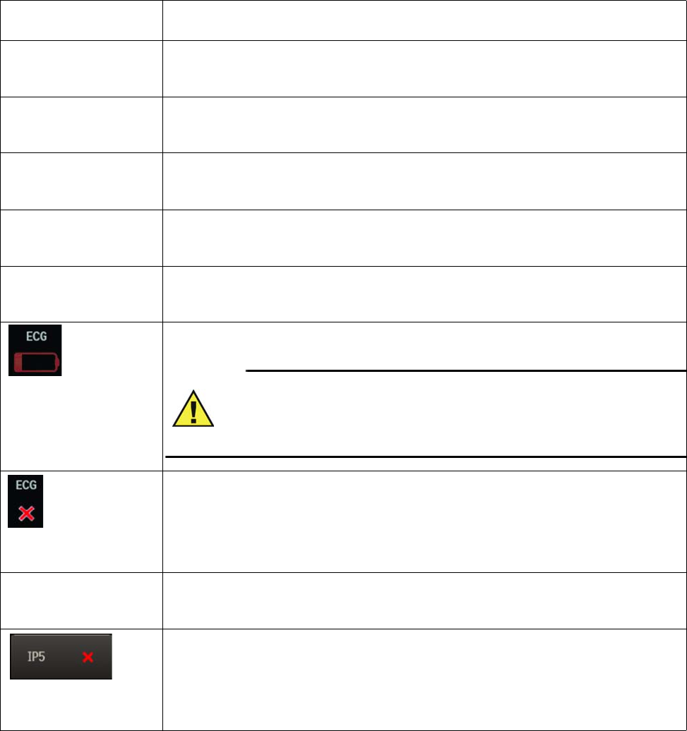
4‐38AlarmsExpressionMR400InstructionsforUse
Other Status Indications
Message, Location,
Indication
Condition
All Alarms Are Off
System message area, no
alarm light, no alarm tone
All alarm limits have been turned off.
Audio Off
System message area, no
alarm light, no alarm tone
Alarm sound is silenced.
Audio Paused
System message area, no
alarm light, no alarm tone
Alarm sound is paused.
Change NIBP Cuff
System message area, no
alarm light, no alarm tone
The Patient Type was changed so the NIBP cuff should be changed.
Check Alarm Vol
System message area, no
alarm light, no alarm tone
Power was just turned on, settings were recalled.
status information pane, blue
alarm light, INOP alarm tone
The charge level is low for the wECG module battery (or batteries). Install at least one charged
battery into the wECG module.
WARNING
A red battery symbol indicates that the module batteries have fallen below
the required operational output and module shutdown with loss of
monitoring will occur. Immediately replace the module batteries to avoid a
loss in monitoring.
Status information pane, no
alarm light, no alarm tone
No communication between the MR400 and wECG module. Ensure that the wECG module is set
to the same network channel as the MR400 cart. If both are the same, use an alternate setting.
If the indication persists, contact technical support or authorized service personnel.
ECG Test Signal
System message area, no
alarm light, no alarm tone
The ECG Test Signal is on.
Status information pane, no
alarm light, no alarm tone
No communication between the MR400 and IP5. Ensure that the IP5 is set to the same network
channel as the MR400 cart. If both are the same, use an alternate setting.
If the indication persists, contact technical support or authorized service personnel.
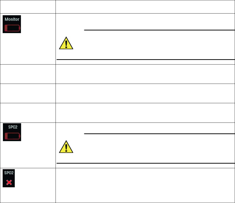
ExpressionMR400InstructionsforUseAlarms4‐39
Status information pane, blue
alarm light, INOP alarm tone
Charge level of the cart batteries is low. Connect the MR400 cart to external power and allow the
batteries to charge.
WARNING
A red battery symbol indicates that the main batteries in the MR400 have fallen
below the required operational output and system shutdown with loss of monitoring
will occur. Immediately locate an AC outlet and connect the MR400 to avoid a loss in
monitoring.
Overscale
ECG alarm flag area, no
alarm light, no alarm tone
The size of the ECG waveform is too large and the tops of the ECG waveforms are clipped (that is,
cut off). Reduce the size using the Scale setting; see page 5-28.
Real Tones Disabled
System message area, no
alarm light, no alarm tone
Normal audio sounds are suspended as a volume adjustment is in progress.
Simulation
System message area, no
alarm light, no alarm tone
The system is in simulation mode. Turn off power to exit this mode.
Status information pane, blue
alarm light, INOP alarm tone
Charge level of the wSpO2 module battery is low. Install a charged battery into the wSpO2 module.
WARNING
A red battery symbol indicates that the module batteries have fallen below
the required operational output and module shutdown with loss of
monitoring will occur. Immediately replace the module batteries to avoid a
loss in monitoring.
Status information pane, no
alarm light, no alarm tone
No communication between the MR400 and wSpO2 module. Ensure that the wSpO2 module is set
to the same network channel as the MR400 cart. If both are the same, use an alternate setting.
If the indication persists, contact technical support or authorized service personnel.
Message, Location,
Indication
Condition
4‐40AlarmsExpressionMR400InstructionsforUse

ExpressionMR400InstructionsforUseMonitoringECG5‐1
CHAPTER 5
Monitoring ECG
Electrocardiogram(ECG)monitoringinsidetheMRIenvironmentisuniqueandrequires
additionalprecautionstopermitsafepatientprocedures.Itisalwaysimportanttoremember
thattheriskofradiofrequency(RF)heatingiseverpresentwhenanyelectricalconductors(for
example,ECGleadcables)areplacedintheMRsystembore.Byfollowingtheoperating
precautions,warningsandtheguidelinesbelow,theseriskscanbeminimized.TheECG
parameterisintendedforECGmonitoringmodeandnotdiagnosticECGmonitoring.
WARNINGS
•The MR400 is not intended for use with patients using pacemakers or electrical
stimulators.
• Arrhythmias, erratic heartbeats, operation of electrical stimulators, pacemakers and
patient motion can result in inaccurate readings. Rate meters may continue to count
pacemaker rates during occurrences of cardiac arrest or some arrhythmias. Do not
rely entirely upon rate meter alarms. If questionable readings are obtained, check the
patient's vital signs by alternate means before administering medication.
CAUTION
Pacer pulses are not specifically rejected by the MR400 and may be treated as part of MRI
gradient noise. Gradient filtering attempts to remove high frequency pulse-shaped waveforms
from the ECG signal which may resemble pacer waveforms, and it is possible that the pacer
waveform may be removed with the gradient noise.
ECG Monitoring Considerations for the MR Environment
MonitoringECGintheMRenvironmentisparticularlychallengingbecauseoftheinherent
distortionoftheECGwaveformcausedbythecombinedelectromagneticfieldsgeneratedbythe
MRIscanner.Inparticular,certainECGinterferenceappearswhenthepatientisplacedinsidethe
borebeforescanningbegins.ThesebloodflowinduceddistortionsoftheECGareduetothe
largeamountofbloodmovingthroughthevesselsoftheheart(aorta).Blood(averygood
electricalconductor)movingthroughthelargemagneticfieldoftheMRproducesanelectrical
potentialthataddstotheECGsignal.Thisinducedelectricalpotentialisseenprimarilyasan
augmentationoftheECGT‐waveamplitude,althoughothernon‐specificwaveformchangesare
alsoapparentontheECG.SinceanelevatedT‐waveorSTsegmentwillbeassociatedwithtrue
physiologicdisorders,thestaticmagneticfield‐inducedECG‐distortionsmayprohibiteffective
ECGmonitoringintheMRI.Forthisreason,abaselinerecordingoftheECGpriortoslidingthe
patientinsidetheboreoroutsidetheMRmagnetroomwillbenecessary.
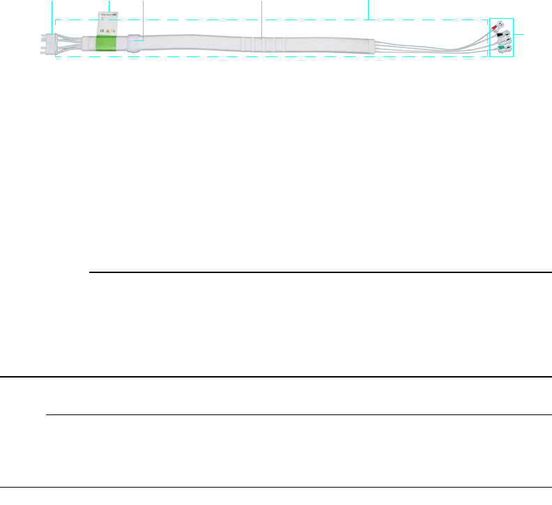
5‐2MonitoringECGExpressionMR400InstructionsforUse
TheproperplacementoftheECGelectrodesintheMRIiscriticaltoreducingthebloodflow
induceddistortionoftheECGwaveform.WithproperstrategicplacementoftheECGelectrodes
andminimizationofECGleadcablelength,thisbloodflowinduceddistortioncanbekepttoa
minimum,asdiscussedinthissection.Additionalartifactscausedbythestatic,gradientandRF
electromagneticfieldscanseverelydistorttheECG,makingobservationofthemorphologic
changesanddetectionofarrhythmiaquitedifficult.MonitoringusingadifferentECGleadview(I,
II,III,AVL,AVR,AVF)willminimizesomeoftheseartifacts.
wECG Module and ECG Lead Cable
ThewECGmoduleandleadcableareintendedforpatientuseswhencontinuousECGmonitoring
orcardiacgatingarerequired.ThewECGmoduleandleadcablemaybeusedintheMRsystem
bore,althoughthemodulemustnotbeplacedwithin28cm(11inches)oftheMRIfieldofview
(FOV).ForwECGmoduledetails,seepage2‐9.ThecomponentsoftheECGleadcablearedetailed
below.
.
CAUTIONS
• If dropped, the wECG module must be verified for correct operation before use; see page
14-12.
• Guard against the accidental ingress of liquid into the module, as measurements made by the
device can be adversely affected.
Note
Refer to your facility's biohazard procedure for disposal of ECG lead cables when they become
unusable. Usually cables are disposed of as medical waste per facility procedures.
1Connector
2ECG lead cable label identifier
3Velcro storage strap
4Cable trunk with foam insulator
5Lead wires
6Lead cable clips
123
6
4 5
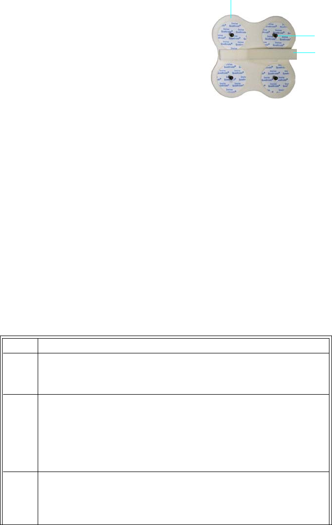
ExpressionMR400InstructionsforUseMonitoringECG5‐3
Quadtrode Electrodes
TheQuadtrodeelectrodesserveaspatientconnectionpointsfor
theECGleadcableclips.DifferentQuadtrodeelectrodesare
availabletomeeteachmonitoringrequirement.The
componentsofaQuadtrodeelectrodearedetailedbelow.
Work Flow for ECG Monitoring
WhenmonitoringECG,manyfactorswillimpacttheperformanceandoperationofthe
parameter,including:
•Thesiteselectedonthepatient,
•TheECGleadcableandQuadtrodeelectrodepairing,
•Theselectedfilterandleadviewsettingforthemonitor,
•ModuleplacementandECGleadcablerouting;and,
•ScansequenceselectionandscansequenceparametersontheMRIconsole.
ToprepareapatientforECGmonitoring
1Foam insulator
2Electrode contact (four contacts are
provided on the standard and neonatal
types, and one contact on the CV type
3Lead retainer (not present on CV and
neonatal types)
1
2
3
Step Action
1 SelectthePatientType.
SeeSelectingthePatientTypeonpage3‐11.
2 Accordingtothepatienttype,theirbodymass,andthestudytobe
performed,choosearecommendedECGleadcableandQuadtrode
electrodepair.
SeeSelectingtheECGLeadCableandQuadtrodeElectrodeTypeon
page5‐5.
3Decide
wheretoapplytheQuadtrodeelectrodetothepatient.
SeeIdentifyingthePlacementSitefortheQuadtrodeElectrodeon
page5‐7.

5‐4MonitoringECGExpressionMR400InstructionsforUse
4Preptheplacementsite(s)onthepatientandthenapplythe
Quadtrodeelectrodetothepatient.
SeePreparingtheQuadtrodeElectrodeSiteonpage5‐11.
5 AttachtheleadcableclipstothecontactsontheQuadtrode
electrode.
SeeAttachingtheECGLeadCableonpage5‐12.
6EvaluatetheECGsignalstrengthandmakeadjustmentsasneeded
beforethepatiententersthescanner.
SeeCheckingtheECGSignalStrengthonpage5‐16.
7 Positionthepatient,theleadcableandthewECGmodulefor
scanning.
SeePositioningtheECGLeadCableandwECGModuleforScanning
onpage5‐19.
8 SelecttheleadviewandFilterModeforthestudy.
SeeChangingtheLeadViewonpage5‐17andFilterModeonpage
5‐31.
9Beforeslidingpatientinsidethebore,oroutsidetheMRmagnet
room,establishabaselinerecordingofthepatient’sECGsignal.
10 Slidethepatientintothebore,butdonotstartscanning.Then,
rechecktheECGwaveformforusabilitybyevaluatingitfor
distortion.
IfECGwaveformhasbecomeexcessivelydistortedandtheheart
ratenumericisnotfunctioningproperlyinthebore,thentheECG
leadcablemayrequirereroutingand/oranewelectrode
placementsitemustbeselectedbeforestartingthescansequence.
(AlsoseeMinimizingECGWaveformNoiseonpage5‐18.)
Step Action

ExpressionMR400InstructionsforUseMonitoringECG5‐5
Selecting the ECG Lead Cable and Quadtrode Electrode Type
ECGleadcablesandQuadtrodeelectrodesareprotonemissionscompliant,willnotdistortthe
MRimage,andaredesignedtoprovidethemaximumpatientsafetyandMRIperformance:
•OnlyusethespecifiedECGleadcableswiththeMR400,asthesearespeciallyconstructed
toavoidpatientheatingbyreducingtheamountofradiofrequency(RF)energythatcan
flowthroughthewiresandwithashorterlengthtoreducethepotentialforcablelooping.
ThetypeofleadcableneededwilldependuponthetypeofQuadtrodeelectrodebeing
used.
•OnlyusethespecifiedQuadtrodeelectrodewiththeMR400,asthiswillminimizethe
possibleriskofelectrodeheatingduringMRIproceduresandreducetheamountofMRI‐
generatedartifactsontheECGwaveform.ThetypeofQuadtrodeelectrodeneededwill
dependgenerallyuponthepatienttype,genderandweight.(Regardlessofthetype,the
Quadtrodeelectrodewillbeconsideredasingleitemwhendiscussedinthistext.)
11 BeginscansequenceandobservetheECGwaveform.
IftheECGwaveformbecomescompromisedduringscanning,then
changetheleadviewand/ortheFilterModeontheMR400.
Note
ECG performance during MRI scanning can be further improved by
modifying scan sequence parameters at the MRI console. Changing
any of these parameters directly alters image quality so precaution
must be taken to not overwhelmingly affect the desired image
characteristics:
• Increase TE (Echo Time)
• Increase TR (Repetition Time)
• Increase TI (Inversion Time)
• Increase / change the imaging plane (for example, sagittal to
axial)
• Turn off fat suppression
• Decrease the PNS level
• Decrease the gradient strength
12 Afterscanning,disconnectthewECGmodulefromthepatient.
ThenstorethewECGmoduleinthemoduleholder.Loopthecable
trunkwithfoaminsulatorthensecureitusingtheVelcrostorage
straptokeeptheexcesscablelengthfromtouchingthefloor;see
page2‐12.
Step Action
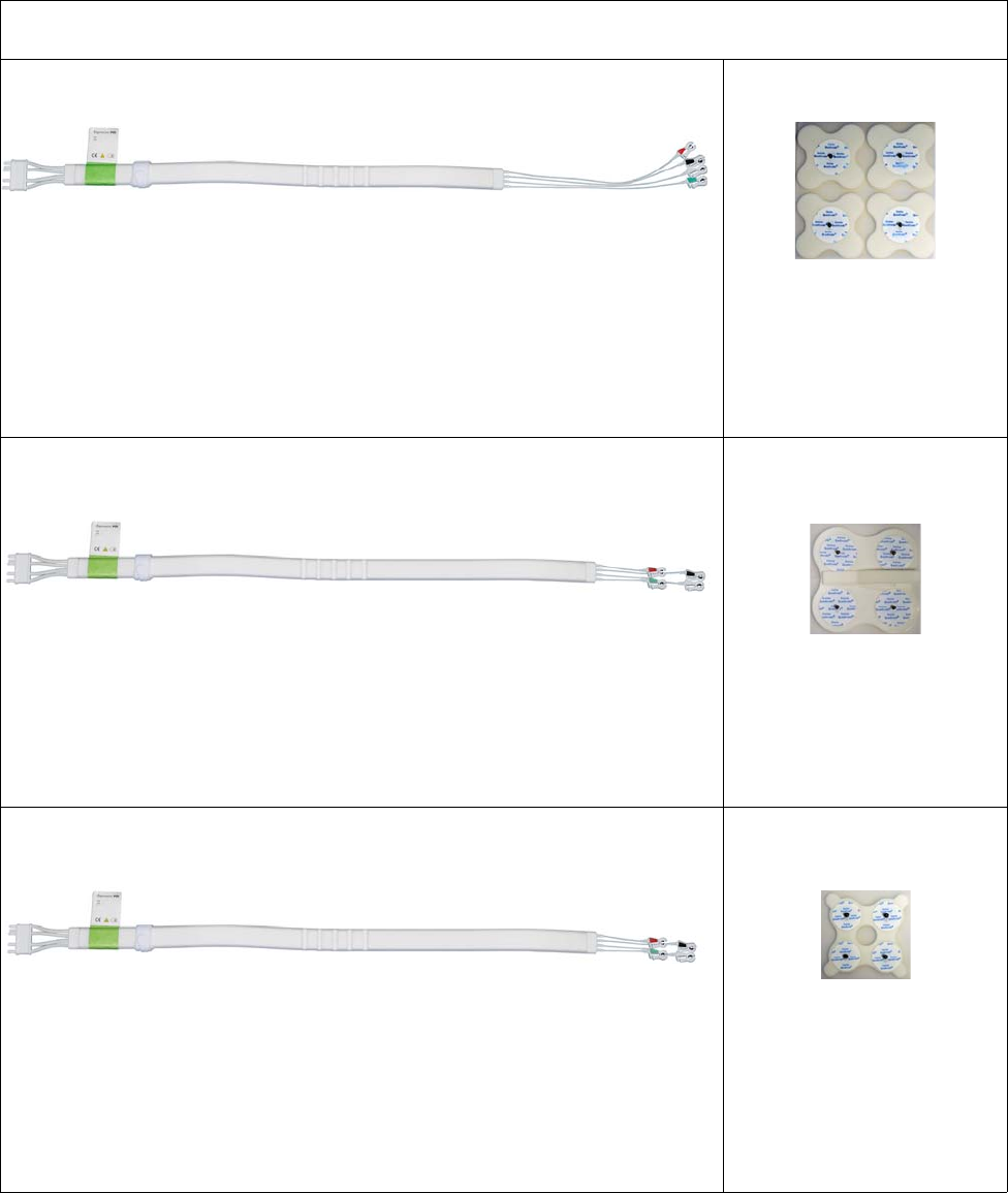
5‐6MonitoringECGExpressionMR400InstructionsforUse
ThetablebelowhighlightstherecommendedusesofECGleadcablesandQuadtrodeelectrodes.
ECG Lead Cables and Quadtrode Electrodes - Recommended Pairings
CV ECG lead cable CV Quadtrode Electrode
Purpose:
• For patients weighing more than 10 kg (22 pounds)
• Best for female and overweight patients (that is, in situations where placement
would be difficult using the standard Quadtrode electrode)
Version and Part Number:
AAMI: REF 989803193721
IEC: REF 989803193751
Part Number:
REF 989803179041
Standard ECG lead cable Quadtrode Electrode
(standard)
Purpose:
• For patients weighing more than 10 kg (22 pounds)
• Quick application
Version and Part Number:
AAMI: REF 989803193731
IEC: REF 989803193761
Part Number:
REF 989803179031
Neonatal ECG lead cable Neonatal (Neo)
Quadtrode Electrode
Purpose:
• For infants weighing less than 10 kg (22 pounds)
• Quick application
Version and Part Number:
AAMI: REF 989803193741
IEC: REF 989803193771
Part Number:
REF 989803179051

ExpressionMR400InstructionsforUseMonitoringECG5‐7
Identifying the Placement Site for the Quadtrode Electrode
Warning
WARNING
Ensure that the location of the electrodes is compliant to the requirements of your
electrosurgical equipment to reduce the possibility of burns; however, note that monitoring
in the MR environment requires specific electrode placement. (See page 5-3 to ensure the
highest quality ECG signal. For questions and guidance regarding placement, contact
technical support; see page 14-16 for contact information.)
Accordingtothepatienttypeorweight,placementoftheQuadtrodeelectrodeovertheheartis
importantforoptimalECGperformance.
Note
For placement purposes, we define to the breast line as an imaginary horizontal line that extends
across the nipple areas of a patient of normal weight.
Adultandpediatricpatients:
•IfusingastandardQuadtrodeelectrode,placeitslightlytotheleftofthepatient’s
sternum,withthetoptwoelectrodesonthebreastlineandthebottomtwoelectrodes
belowthebreastline.
•IfusingaCVQuadtrodeelectrode,attempttokeepasmallseparationbetweenindividual
electrodes—adistancethatiswideenoughtoproperlycapturetheECGvector,butnotso
wideastocauseexcessivenoisepickup.(Increasingtheloopareabetweenelectrodeshas
anegativeeffectonECGqualityuniquetotheMRIenvironmentthatcausesmorenoiseto
bepickedupbytheECGleads).
Neonatalandinfantpatients:
• Dependingonthepatient’sweight,centerastandardQuadtrodeelectrodeoraneonate
Quadtrodeelectrodeoverthesternumandthebreastline.
DeviationsfromtheguidelinesforQuadtrodeelectrodeplacementcanaffecttheproducedECG
signalasfollows:
•Placementsoffsetabovethebreastline:IncreasestheT‐waveamplitudeandthe
susceptibilitytostaticfield(B0)effects.
•Placementsoffsetbelowthebreastline:DecreasestheT‐waveamplitude,increasethe
distancefromtheaorticvalve,thesusceptibilitytostaticfield(B0)effectsandtheECG
waveamplitude.
•Placementsclosertothesternum:IncreasestheECGwaveamplitudeandalsoany
respiration‐inducednoise.
•Placementsfartherfromthesternum:DecreasestheECGwaveamplitudeandany
respiration‐inducednoise.
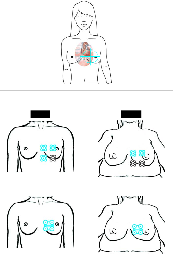
5‐8MonitoringECGExpressionMR400InstructionsforUse
ThediagramsbelowillustrateQuadtrodeelectrodeplacementsite(s)accordingtopatienttype,
includingthepreferredQuadtrodeelectrodetypeandlocationfordifferentpatientbodysizes.
Selectingsitesonadultfemalepatients
*Where grayed images indicate placement sites against the ribcage under the breast.
Average weight adult female* Overweight adult female*
CV Quadtrode
Preferred
CV Quadtrode
Preferred
Standard Quadtrode Standard Quadtrode
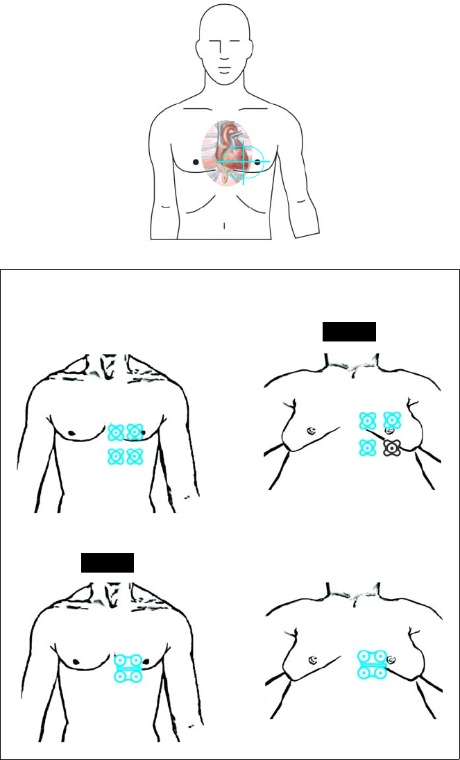
ExpressionMR400InstructionsforUseMonitoringECG5‐9
Selectingsitesonadultmalepatients
*Where the grayed image indicates a placement site against the ribcage under the breast.
Average weight adult male Overweight adult male*
CV Quadtrode CV Quadtrode
Preferred
Standard Quadtrode
Preferred
Standard Quadtrode
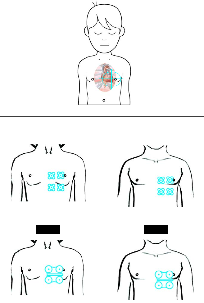
5‐10MonitoringECGExpressionMR400InstructionsforUse
Selectingsitesonpediatricpatients
Pediatric female Pediatric male
CV Quadtrode CV Quadtrode
Standard Quadtrode
Preferred
Standard Quadtrode
Preferred
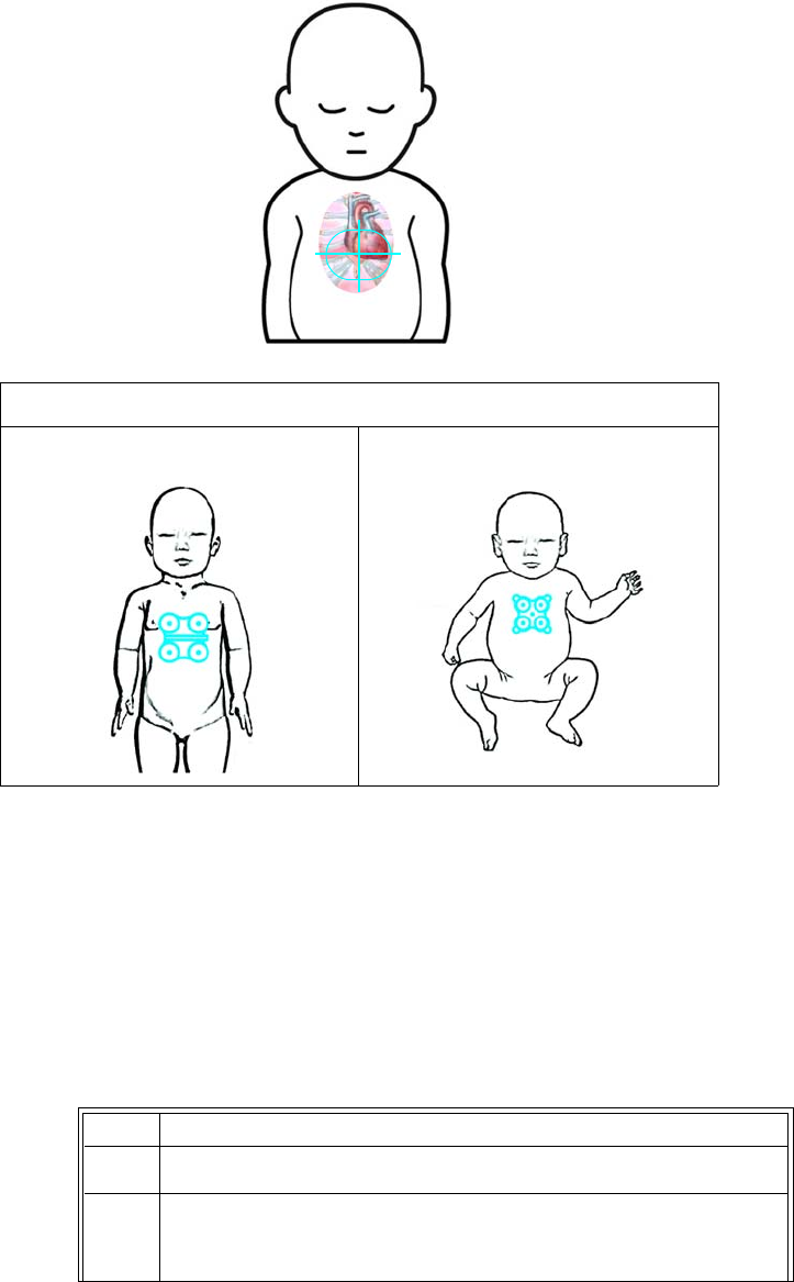
ExpressionMR400InstructionsforUseMonitoringECG5‐11
Selectingsitesoninfantsandneonatalpatients
Preparing the Quadtrode Electrode Site
ProperpreparationfortheapplicationoftheQuadtrodeelectrodeiscriticaltoECGperformance.
TheresultofpoorapplicationpreparationwillbepoorECGmonitoringperformance.Ifelectrode
contactwiththeskinispoor,thenremoveanddiscardtheQuadtrodeelectrode,andrepeatthe
sitepreparationprocessagainaccordingtotheinstructionsbelow.NeverreuseaQuadtrode
electrodebecauseitwillnotsecurelyadheretotheskin.
ToprepareaQuadtrodeelectrodesiteonapatient
Infants and Neonates
Standard Quadtrode Neonatal Quadtrode
Step Action
1ChecktheexpirationdateoftheQuadtrodeelectrodepackage.
2 Selecttheapplicationarea(s),avoidingtheareolaandnipplewhen
possible,fortheQuadtrodeelectrodesite(s)asprovidedonpage5‐
7.
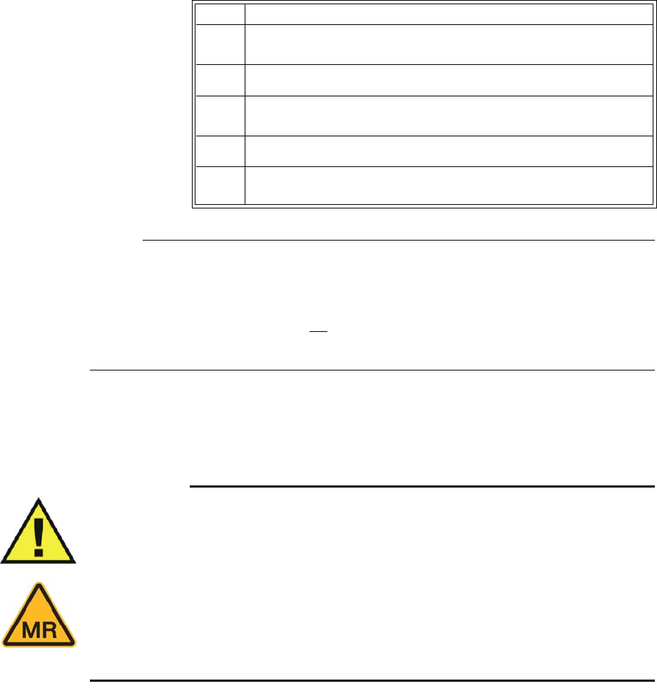
5‐12MonitoringECGExpressionMR400InstructionsforUse
Notes
• The ECG Skin Prep gel contains light abrasive pumice and saline that clean and enhance
the conductive properties of the skin, thus enhancing ECG performance. This practice also
helps remove ambient artifacts.
• Isopropyl/rubbing alcohol must not be used to prep the site as it breaks down the conductive
properties of the skin, thus degrading ECG performance.
Attaching the ECG Lead Cable
WARNINGS
• Never use any ECG lead cables other than the specified ECG lead cables.
• High levels of RF energy may cause patient heating or burns.
• An ECG lead cable that becomes inadvertently looped during an MRI examination
may act as conductive lines for RF induced currents, resulting in excessive heating and
possible burns. When lead cables or other cables form a conductive loop in contact
with the patient's tissue, minor to severe burning can result. Please refer to the
additional information in Appendix E to prevent excessive heating associated with
MRI procedures. Follow steps to minimize the risks of MRI-related heating on page 5-
20.
Giveninrelationtothepatient’slimbs,designatorsandcolorsoftheECGleadcableclips
referenceconnectionlocationsontheQuadtrodeelectrode.Also,notethatdependinguponthe
leadcableversion,AAMI(AssociationfortheAdvancementofMedicalInstrumentation)orIEC
(InternationalElectrotechnicalCommission),differentdesignatorsandcolorsareusedforthese
references.ThediagramsbelowillustratetheleadcableattachmentlocationstotheQuadtrode,
accordingtotheECGleadcableversionandlimb.
Step Action
3Ifnecessary,shavetheapplicationareatoremovehairfromthe
selectedQuadtrodeelectrodesite(s).
4ApplyECGSkinPrepGel(REF989803152291)toagauzepad.
5Briskly
rubtheselectedsite(s)withthegauzepad(theskinmay
turnpink).
6 Removeanyexcessgelwithacleangauzepad.
7PlacetheQuadtrodeelectrodeatthepreparedsite(s)onthe
patient.
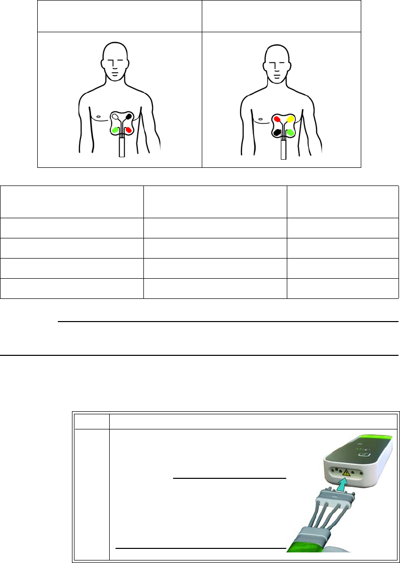
ExpressionMR400InstructionsforUseMonitoringECG5‐13
CAUTION
ECG lead cable clips should not be placed on the patient’s extremities.
ToattachtheECGleadcabletothewECGmoduleandthentotheQuadtrodeelectrode
contacts
AAMI ECG Lead Cable
Connections
IEC ECG Lead Cable
Connections
AAMI ECG Lead Cable Clip
Designator / Color
IEC ECG Lead Cable Clip
Designator and Color Associated Limb
RA / White R / Red Right arm
RL / Green N / Black Right leg
LA / Black L / Yellow Left arm
LL / Red F / Green Left leg
Step Action
1InserttheconnectoroftheECGlead
cableintothecableportonthewECG
module.
CAUTION
When inserting or removing the lead
cable, only use the connector as a
finger-hold; never pull or apply
excessive force to the wires.

5‐14MonitoringECGExpressionMR400InstructionsforUse
2 DependingupontheECGleadcabletype,attachtheclipstothe
Quatrodeelectrodecontacts,asshownintheappropriate
connectiondiagramonpage5‐12.Squeezeeachclipopenthen
placetheclipontotheelectrodecontactandrelease.
CAUTION
When inserting or removing the clip leads, use the clip as the finger-
hold; never pull or apply excessive force to the wires.
3IfusingastandardQuadtrodeelectrode,securetheleadcable
wiresusingtheleadretainer.
Seepage5‐3forthelocation.
4CheckthebatteryindicatorsonthewECGmoduletoensurethat
enoughchargeexistsinatleastoneoftheinstalledbatteries:
• Greenbatteryindicator=Chargesufficient;proceedtostep6.
•Redbatteryindicator=Chargelow;proceedtostep5.
Seepage2‐9fordetails.(Also,youcanreferencethestatus
informationpane;seepage2‐16.)
5 Accordingtotheredbatteryindicator(s)presentonthewECG
module,insertachargedmodulebatteryintothecorresponding
batterybay(s)andthenrecheckthebatteryindicator(s)toensurea
sufficientchargebeforeproceeding;seepage1‐24.
6CheckthenetworkchannelindicatoronthewECGmoduleto
ensurecommunicationisestablishedwiththeMR400:
• Steady=Goodcommunication;proceedtostep8.
• Flashing=Nocommunication;proceedtostep7.
Seepage2‐10fordetails.(Also,youcanreferencethestatus
informationpane;seepage2‐16.)AninoperativeECGparameteror
wECGmoduleisindicatedbyabsenceofanECGwaveformanda
simultaneousLeadFailalarm.
7EnsurethatthewECGmoduleiswithin9.1m(30feet)ofthe
MR400,inthesameMRIroomorinthesameshieldedroom,andis
settothesamewirelessnetworkchannelusedbytheMR400;see
page1‐29.
Step Action
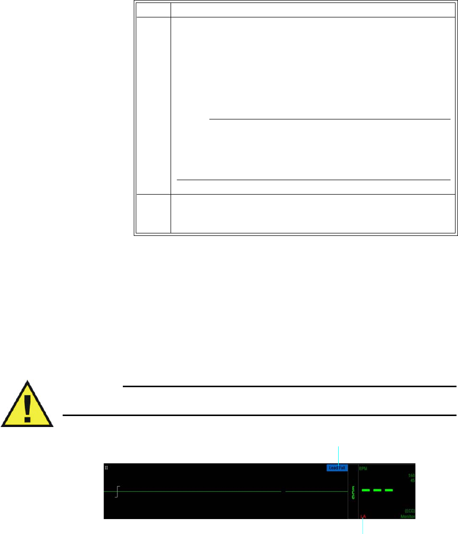
ExpressionMR400InstructionsforUseMonitoringECG5‐15
Lead Fail Indication
LeadFail(illustratedbelow)isanINOPalarmthatwillbedisplayedwhentheECGtracecanno
longerbeproducedbecauseoneoftheelectrodesrequiredformeasurementisdisconnected—
eitheranelectrodecameoffofthepatient,anECGleadcableclipcameoffoftheelectrode,ora
wireintheECGleadcablehasfailed.DependingupontheTraceALead(orTraceBLead)setting
(seepage5‐27),theelectrodefaultindicator(s),LL,LA,orRA,maybedisplayedintheECGVSbox
(seetheexamplebelow);seepage4‐31formoreinformation.
Warning
WARNING
Failure to respond to a Lead Fail alarm will result in a lapse of patient monitoring.
8EnsurethattheECGsignalhasthenecessaryamplitudebychecking
thedisplayedwaveform;seeCheckingtheECGSignalStrengthon
page5‐16.
IfLeadFailisdisplayed,seepage5‐15fortroubleshootingdetails;
or,ifLeadSaturationisdisplayed,replacetheQuadtrode
electrode,seepage5‐11.
Note
During a Lead Fail condition, if the HR Source is set to ECG, then no HR
measurement numeric will be displayed in the ECG and SPO2 VS
boxes; see page 5-15 for an example.
9 KeepthemoduleoutsidetheMRsystemborebyplacingitinone
ofthetwolocationsshowninPositioningtheECGLeadCableand
wECGModuleforScanningonpage5‐20.
Step Action
1Lead Fail message indication
2Electrode fault indication, example
2
1
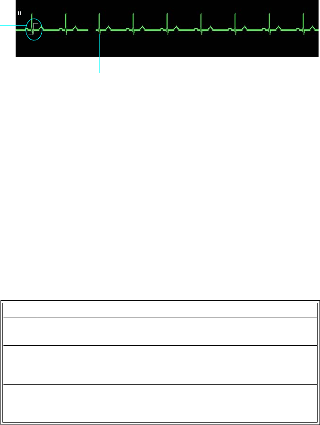
5‐16MonitoringECGExpressionMR400InstructionsforUse
Checking the ECG Signal Strength
EvaluatetheECGsignalproducedbythepatientbeforeentryintotheMRIscanner,the
optimumtimetocorrectanyproblem.
Aminimumsignalstrengthshouldbepresent,asweakersignalsmaybepronetogradient
interference:
• SelectScaletoadjustthedisplayedsizeofthewaveform(s),wherethescaleindicator
provides,a1millivolt(mV)referenceatanygivensetting;seeSelectingtheScale,below).
• SelectTraceALead(orTraceBLead)toadjusttheconfigurationoftheleadsusedforECG
signaldetection,wherethebestsignalstrengthisindicatedbythedisplayedpeak‐to‐peak
amplitudeoftheQRScomplex,whichshouldbeatleast1mV(thatis,thewaveform
shouldbeequaltothesizeofthescaleindicator).Insomecases,a1mVECGsignalcannot
beachievedduetopatientphysiology.Inthesecases,trytoachievethelargestamplitude
attainable.SeeChangingtheLeadView,onpage5‐17.
Selecting the Scale
TheScalesettingonlychangeshowtheECGtraceappearsonthescreen—increasingor
decreasingthewaveformandanyartifacts.ToincreasetheamplitudeoftheQRScomplex,refer
toChangingtheLeadViewonpage5‐17.
TochangetheSCALEsetting
Scale indicator
QRS complex
Step Action
1EnsurethatthecorrectPatientTypehasbeenselected;seepage3‐
11fordetails.
2 SelecttheECGVSbox.
TheECGmenuappears.Currentsettingsaredisplayed.
3 SelectScale.
TheScalemenuappears;seepage5‐28.

ExpressionMR400InstructionsforUseMonitoringECG5‐17
Changing the Lead View
IftheQRScomplexdoesnotequalaminimumof1mVpeak‐to‐peak,thencompletethe
followingstepstomakethewaveformamplitudeincrease.
Tochangetheleadview
4 Selectthesetting.Onlyasettingof5xor10xisrecommended.
Auto
1x
5x
10x
15x
20x
25x
30x
40x
Thesettingisapplied.
5Takenoteofthescaleindicator;seepage5‐22.Iftheselectedscale
resultsinanECGtracesolargethatthewaveformpeaksare
distortedorclipped,Overscalewillbedisplayed.Inthiscase,select
anothersettingtoresizethewaveformuntilthemessagestops.
Step Action
Step Action
1VerifythataQuadtrodeelectrodeorQuadtrodeelectrodesare
beingused,andverifytheexpirationdate,qualityandpackaging
fortheelectrode.
2EnsurethatthepreferredQuadtrodeelectrodeisbeingused;see
page5‐5.
3Ensurethatthesuggestedplacementsite(orsites)isbeingused;
seepage5‐7.
4 SelecttheECGVSbox.
TheECGmenuappears.Currentsettingsaredisplayed.
5 Dependinguponthetracebeingexamined,selectTraceALeador
TraceBLead.
Therespectivemenuappears.Thecurrentsettingishighlighted.
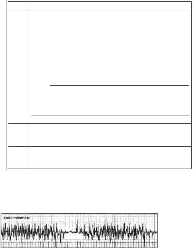
5‐18MonitoringECGExpressionMR400InstructionsforUse
Minimizing ECG Waveform Noise
NoisecanrenderanECGwaveformunusable,asshownintheexamplebelow.
ManycausescanresultinanoisyECGwaveform,including:
•Useofalcohol‐basedproductsduringpatientprep.
•UseofaQuadtrodeelectrodethatisexpiredordried‐out.
•UseofwrongordamagedECGcableleads.
•ImproperplacementoftheQuadtrodeelectrode.
•PlacingtheMR400insidethe5000gaussline.
•PlacingthewECGmoduleinsidethebore.
•MRvibrationsaffectingthewECGmodule.
• Incorrectnotchfiltersetting;seepage5‐22.
6 Selectthedesiredleadviewsetting.
I
II
III
AVL
AVR
AVF
Thesettingischanged.
Note
When presented with poor gating or heart rate performance, it may
be necessary to use the Pediatric ECG setting; see page 5-32.
7Iftheamplitudedidnotimprove,repeatstep5andcyclethrough
theremainingleadviewsettingsuntila1mVsignalamplitudeis
attained.
8Iftheamplitudedidnotimprove,removetheECGleadcableand
theQuadtrodeelectrode.Thenpreptheapplicationsiteagainand
applyanewQuadtrodeelectrode.
Step Action

ExpressionMR400InstructionsforUseMonitoringECG5‐19
• SelectingMonitorastheFilterModeforthescansequence;seepage5‐31.
•Scansequenceparameters.
•ImproperconnectionofECGleadcabletoQuadtrodeelectrodecontactlocations.
•RoutingtheECGleadcableadjacenttothebodycoilorunderneathanextremitycoil.
• ExcessivedistancebetweenelectrodeswhenusingCVQuadtrodeelectrodes.
Positioning the ECG Lead Cable and wECG Module for Scanning
WARNINGS
• When applying electrodes or connecting the ECG lead cable, ensure that the electrodes
or connectors never contact other conductive materials including grounded
conductors. In order to prevent contact with other conductors or earth ground, make
sure all the electrodes or connectors are properly attached to the patient.
• No other electrical conductors (e.g. wires, leads, probes, et cetera) should be placed
within the MRI bore at the same time as the ECG lead wires. Electrode heating risk
increases when multiple conductive cables and probes are placed in the bore with the
patient. Mixing of conductors from various manufacturers (catheters, temperature
sensors, et cetera) is not recommended. Multiple electrical conductors within the MRI
bore can allow cross-coupling between these various conductors, and appear as a large
antenna for RF energy pick-up, which will result in electrode heating, and possibly
skin burns. It is always important to identify if the patient has any metallic wires,
conductors, implants, stents, et cetera. within their body which will act as cross-
coupling conductors. If these are present, ECG monitoring may not be able to be
performed without experiencing electrode heating. Non-conductive tubes, air-lines, et
cetera—including NIBP cuffs and hoses, EtCO2 and/or oxygen air-lines, and SpO2
probes—can be used safely as these items do not include electrically conductive
materials. The MR400 has been validated for use with all accessories specified in the
accessory list; see page 1-33.
• Circular, U-shaped or S-shaped loops in the ECG lead cable should be avoided to
reduce the risk of heating.
• Do not use the Velcro storage strap to loop the ECG lead cable during MR scanning;
otherwise, there is a risk of cable heating and possibly skin burns.
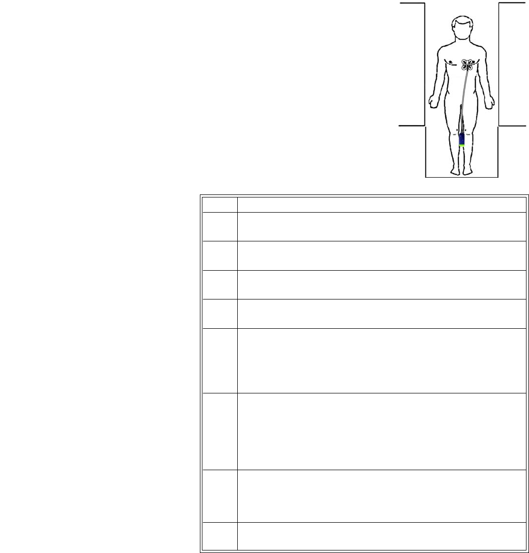
5‐20MonitoringECGExpressionMR400InstructionsforUse
PositioningtheECGleadcable
PositionandkeeptheECGleadcablesinastraightline.Never
allowtheECGleadcablestotouchtheMRsystembore.Any
loop(circular,U‐shaped,S‐shaped)inthecablesorcable
contactwiththeMRsystemborewillcauseheatinginthe
cablesorinthepatientelectrodes.Followthestepsbelowto
minimizethecableheatingrisk.
TominimizetheriskofMRI‐relatedheating
Step Action
1ArrangetheECGleadcableandtheclipleadsneatly,inastraight
alignment,withnolooping.
2Avoidcontactbetweencablesandbareskin.CushionthewECG
module.
3UseonlytheECGleadcablesdesignatedforusewiththisproduct;
seepage1‐35.
4 Minimizetheuseofmultiplecables.(Seethewarningsonpage5‐
19fordetails.)
5ThewECGmodule,ECGleadcablesandQuadtrodeelectrodeare
acceptableforusewithinMRsystemswithstaticmagneticfield
strengthsof3.0Tesl a orlesswithintheMRsystemboreusingaMR
systemreportedwholebodyaverageSpecificAbsorptionRates
(SAR)upto4.0W/kg.EnsurethatB1rms<7.2μT.
6 MonitoringofECGatpowerlevelsofgreaterthanaMRsystem
reported,wholebodyaveragedSARof4W/kgisnotrecommended
forthegeneralpatientpopulation.Suchmonitoringmustonlybe
attemptedwithconsciouspatientswithnormalthermoregulatory
capabilitiessothattheymaywarnyouofpossibleexcessiveheatat
themonitoringsites.
7Usecautionforscantimes(thatis,perpulsesequence)greater
than15minutes.ForMRIscanswithaverageSAR>1W/kg,limit
scantimeto15minutesandpauseatleast3minutesbetween
scanstoallowtheECGelectrodestocool.
8Duringmeasurement,checkthepatienttoensurethatMRI‐related
heatingisnotoccurring.
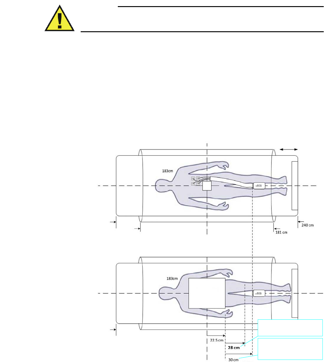
ExpressionMR400InstructionsforUseMonitoringECG5‐21
PositioningthewECGmodule
Warning
WARNING
The wECG module must be kept outside the system bore or image distortion may result.
This is a result of proton emissions from the ECG module.
Dependinguponyourregionofinterest(ROI)andthelargestfieldofviewbeingexamined(see
illustrationbelow),followtheseguidelinestoensurethebestperformanceofthewECGmodule,
especiallyduring harshscansequences:
•Forstaticfield(B0)compliance,keepthemoduleatleast28cm(11inches)outsidethe
MRIfieldofview.
• Consideringthescantobeperformed,placethemoduleonornearthepatientandas
closetotheboreiso‐centeraspossible.
•Placethemoduleasclosetotheboreopeningaspossible.(Ifthemodulecanbeplaced
outsidethebore,positioningattheboreiso‐centerisnotnecessary.)
•PlacethemoduleonacushionedsurfacetominimizeMRvibrations.
Magnet type: Achieva 3.0T XR Series
Male:
ROI
Largest FOV
(45 cm)
Bore Iso-center
Patient Table
MRI Bore
Male:
Patient Table
MRI Bore
Bore Iso-center
For B0 compliance always keep the
wECG module 28 cm from the edge
of the FOV.
For example, a lower abdomen scan
places the module at an acceptable
distance of 30 cm (considering the
length of the ECG cable)
5‐22MonitoringECGExpressionMR400InstructionsforUse
Warning
WARNING
If the wECG module is positioned incorrectly when used within the MR magnet room, the
following factors may cause ECG waveform distortion and numeric inaccuracies:
• Fast magnetic field changes usually found with, but not limited to, scan sequences
using Peripheral Nerve Stimulation (PNS) levels above 80 percent.
• Severe vibrations induced by scan sequences using PNS levels above 80 percent.
• The distance from the bore iso-center in the x, y, or z directions.
Selecting the Filter Mode
ChoosetheappropriateECGfiltermodeforyourMRIstudy;seepage5‐31formodedetails.
Tochangethefiltermodesetting
ECG Waveforms and VS Box
TheECGmeasurementisdisplayedaswaveformsintheVStraceareaofthescreenandas
numericinformationintheECGVSbox.Otherdata,includingECG‐relatedalarminformation,are
alsoprovidedinthisareaofthescreen,asdetailedbelow.
Step Action
1PresstheECGFilterkey.
TheFilterModemenuappears.Thecurrentsettingishighlighted.
2 Selectthedesiredfilter.
Monitor
Default
Advanced1
Advanced2
Thesettingisapplied,asindicatedinECGVSbox.
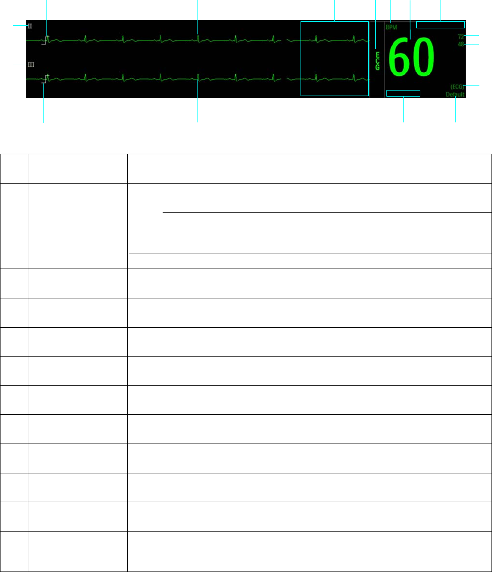
ExpressionMR400InstructionsforUseMonitoringECG5‐23
Item Name Definition
1 ECG VS waveform Is the ECG waveform (Trace A, when enabled)
Note
To change the waveform speed, see Sweep Speed on page 3-25.
2 Alarm flag area Displays ECG alarm flags when detected; see page 4-31.
3 ECG VS box label Indicates the ECG vital sign parameter, and accesses the ECG menu
4 Unit of measure Indicates that the heart rate numeric is given in BPM (beats per minute)
5 Heart rate numeric Is the patient’s detected heart rate measurement
6 Magnet indication Indicates Magnet Filter when engaged.
7 HR upper alarm limit Is the upper limit setting for the heart rate alarm, and accesses the HR Alarm Limits
menu
8 HR lower alarm limit Is the lower limit setting for the heart rate alarm, and accesses the HR Alarm Limits
menu
9 HR source Indicates the source used to measure the heart rate
10 Filter mode Indicates the active ECG filter mode; see page 5-31.
11 Electrode fault
indication
Displays the electrode fault indicator(s) when a disconnected ECG lead or bad electrode
is detected, where LL = left leg, LA = left arm, and RA = right arm; and, LL, LA, RA, = RL
right leg or all leads
123456
7
8
15
14
12
16
9
10
13 11
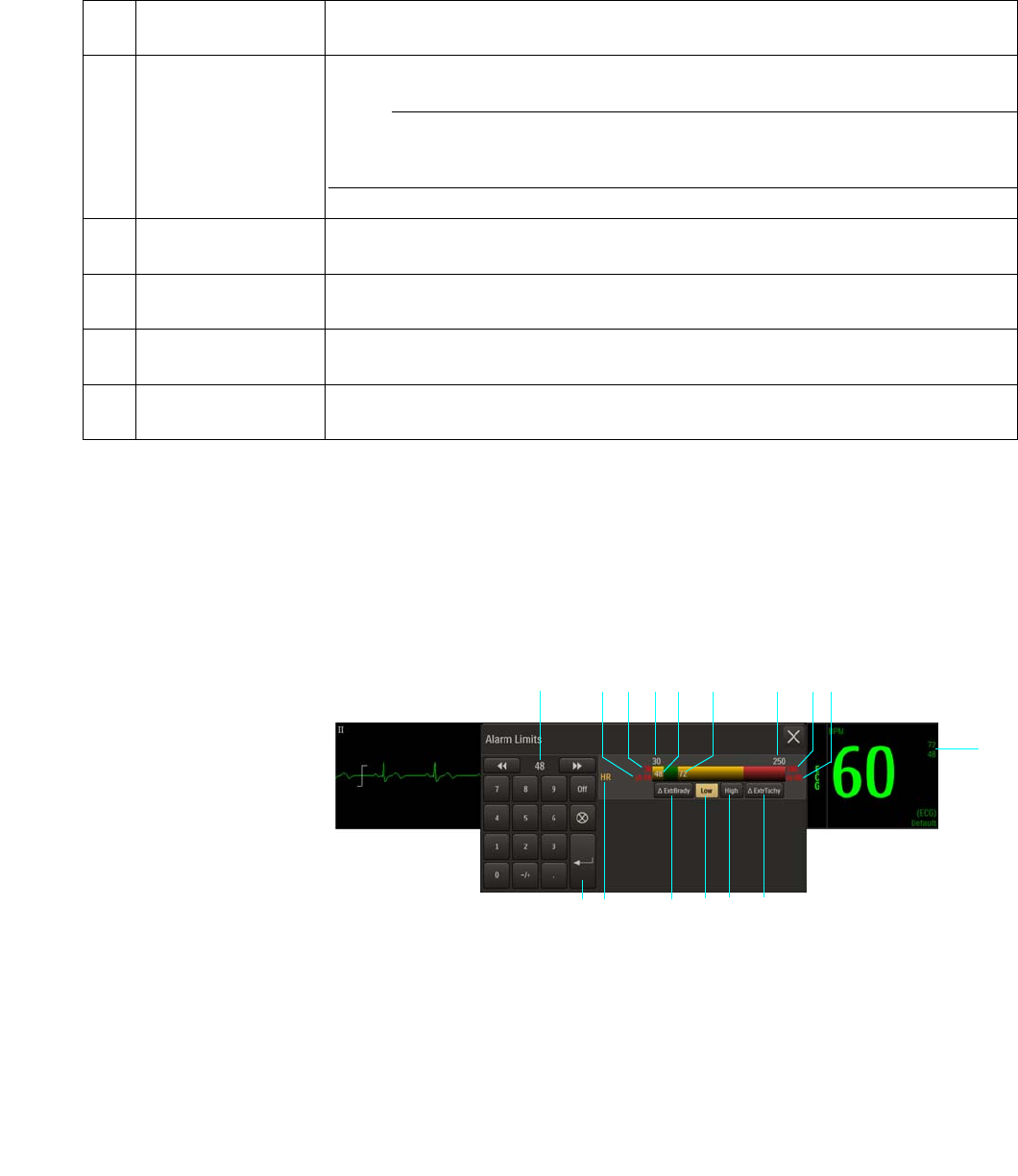
5‐24MonitoringECGExpressionMR400InstructionsforUse
* The displayed waveform should at least be equal to the size of this indicator, as signals with lower amplitudes may be prone to
gradient interference; see Checking the ECG Signal Strength on page 5-16 for details.
Changing the Heart Rate Alarm Limits
TheHeartRateAlarmLimitsmenucanbeaccessedbytouchingthealarmlimitsettingsintheECG
VSbox.
12 ECG VS waveform Is the ECG waveform (Trace B, when enabled)
Note
To change the waveform speed, see Sweep Speed on page 3-25.
13 Scale indicator Represents a 1 millivolt signal amplitude for the selected scale of Trace B*
14 Lead type Is the selected ECG lead for Trace B
15 Lead type Is the selected ECG lead for Trace A
16 Scale indicator Represents a 1 millivolt signal amplitude for the selected scale of Trace A*
Item Name Definition
1Alarm limit settings, ECG VS box
2Extreme Tachycardia button
3High button
4Low button
5 Extreme Bradycardia button
6 HR Alarm Limits menu label
1
2
3
4
5
6
7
8 9 10 11 12 13 14 15 16

ExpressionMR400InstructionsforUseMonitoringECG5‐25
Tochangetheheartratealarmlimitsettings
Note
See chapter 4 for detailed alarm limit setting instructions and options.
7Enter button
8Current adjustment
9Extreme Bradycardia delta value
10 Extreme Bradycardia alarm setting
11 Alarm limit, minimum
12 Lower alarm limit setting
13 Upper alarm limit setting
14 Alarm limit, maximum
15 Extreme Tachycardia alarm setting
16 Extreme Tachycardia delta setting
Step Action
1 SelectthealarmlimitsettingsintheECGVSbox.
TheHRAlarmLimitsmenuappears.Currentsettingsaredisplayed.
2 SelecttheLow,High,∆ExtrBrady,or∆ExtrTachybutton.
Theselectedbuttonwillbehighlightedandthecurrentadjustment
willbedisplayed.
3Usingthekeypad,ortheincrement,decrement,orOffbuttons,
enterthedesiredsetting.
Thecurrentadjustmentwillreflectthesetting.
4PresstheEnterbuttontosavethesetting.
Thealarmlimitsettingisupdated.
5Tochangeotheralarmlimitsettings,repeatsteps2,3,and4.
Thecurrentadjustmentwillreflectthechange.
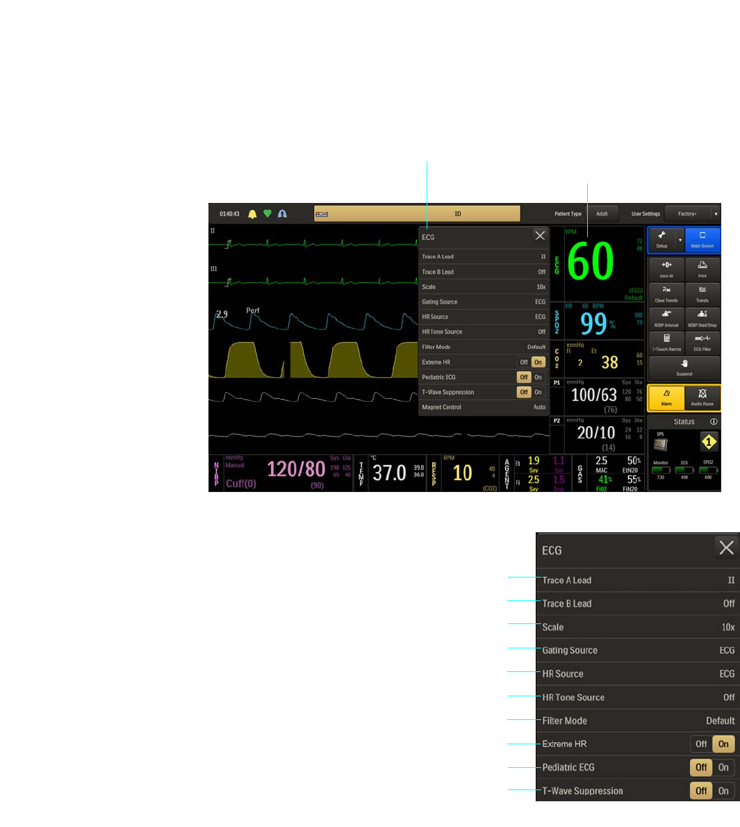
5‐26MonitoringECGExpressionMR400InstructionsforUse
ECG Menu
ECGmenuitemsallowyoutocontrolECGtraces,functionsandsettings.
ToopentheECGmenu
SelecttheECGVSbox.
ThefollowingECGmenuitemsareavailable:.
1 Trace A Lead
2Trace B Lead
3Scale
4Gating Source
5HR Source
6 HR Tone Source
7 Filter Mode
8Extreme HR
9Pediatric ECG
10 T-Wave Suppression
ECG menu
ECG VS box
2
3
4
1
5
6
7
8
9
10

ExpressionMR400InstructionsforUseMonitoringECG5‐27
TochangesettingsintheECGmenu
Trace A Lead
SetstheECG A leadconfiguration(leadview).ForbestECGandheartratemonitoring,always
selecttheoptimalleadview,theonethatprovidestheleastartifactandlargestwaveform
detection.
Thefollowingoptionsareavailable:
•Off
•I
•II(Default)
•III
•AVL
•AVR
•AVF
TosettheECGAlead
Step Action
1 SelecttheECGVSbox.
TheECGmenuappears.Currentsettingsaredisplayed.
2 SelectfromthefollowingECGmenuitems:
TraceALead
TraceBLead
Scale
GatingSource
HRSource
HRToneSource
FilterMode
ExtremeHR
PediatricECG
T‐WaveSuppression
Themenuitemappears.Thecurrentsettingishighlighted.
3 Selectthedesiredsettingfromthemenuoptions(exceptExtreme
HR,PediatricECGandT‐WaveSuppression,whichareselectable
ontheECGmenu).
Thesettingisentered.
4Tochangeothersettings,repeatsteps2and3.

5‐28MonitoringECGExpressionMR400InstructionsforUse
SeeChangingtheLeadViewonpage5‐17.
Trace B Lead
SetstheECG B leadconfiguration(leadview),allowingyoutoviewtwoECGwaveforms
simultaneously.
Thefollowingoptionsareavailable:
•Off(Default)
•I
•II
•III
•AVL
•AVR
•AVF
TosettheECGBlead
SeeChangingtheLeadViewonpage5‐17.
Scale
SetsthescalefortheECG waveforms.Aftermakingthissetting,takenoteofthescaleindicator
(seepage5‐22).Iftheselectedscaleresultsinawaveformwithdistortedorclippedpeaks,
Overscalewillbedisplayedandanothersettingshouldbeselecteduntilthemessagestops.
Thefollowingoptionsareavailable:
•AutomakesthewaveformfilltheECGtracearea(notrecommendedforuseintheMR).
•1x
•5x
•10x(Default)
•15x
•20x
•25x
•30x
•40x
TosettheECGscale
SeeSelectingtheScaleonpage5‐16.

ExpressionMR400InstructionsforUseMonitoringECG5‐29
Note
Scale does not affect the signal analyzed by the MR400 for QRS detection and ECG gating.
Gating Source
SetsthecardiacgatingsourcebasedonameasuredsignalthatisusedforMRsystemtriggering.
(ThisisthesameoptionasintheSPO2menu.)
Thefollowingoptionsareavailable:
•ECGoutputsasignalthatrepresentsthedetectionoftheR‐peakofaQRScomplex.
(Default)
•Pulseoutputsasignalthatrepresentsthedetectionofthepeakoftheperipheralpulse
complex.
Tosetthegatingsource
SeeAppendixDfordetails.
Note
Trace A is the default output channel for interfacing the cardiac gating input. To use Trace B, set
Trace A to off, and ensure that Trace B is active (that is, not off); see page 5-28.
HR Source
Selectsthesourcethatproducestheheartrate,asdisplayedintheECGandSPO2VSboxes
(identicaltoandinteractivewithsameoptionintheSPO2,P1andP2menus).
Thefollowingoptionsareavailable:
•Autosetsthesourceautomaticallyaccordingtothehighestpriorityactiveinputthatisfirst
toreportvalidpatientdata.Thepriorityranking(highesttolowest)isECG,P1,P2,SPO2
(providedthattheP1andP2channelshavebeenlabeledABP;seeSetLabelonpage8‐24
fordetails).Thesourcewillbecomeunavailablewhenithasproducednovaliddatafora
periodoften(10)ormoreseconds.Thesystemexaminesthehighestpriorityactiveinput.
Ifnotfound,thesecond‐highestpriorityinputischosen,etcetera.Ifnonearepresent,
thenNoneisdisplayedastheheartratemeasurementnumeric.
•ECGsetsECGasthesource.(Default)
•ABPsetsABPasthesource(ifnopressurechannelislabeledABP,awarningboxwillallow
automaticrenamingandselectionbeforeproceeding;alsoseeSetLabelonpage8‐24).

5‐30MonitoringECGExpressionMR400InstructionsforUse
•SPO2setsSPO2asthesource.
Tosettheheartratesource
HR Tone Source
Setsthesourceusedfortheheartratetone(identicaltoandinteractivewiththesameoptionin
theMonitorSetup>SoundAdjustmenuandintheSPO2menu).
Thefollowingoptionsareavailable:
•Offremovestheheartbeatdetectedsymbolfromthedisplayandsoundsnopulsetone.
(Default)
•QRSprovidestheheartbeatdetectedsymbolandatonetriggeredbytheQRSdetection
fromtheECGvitalsign.
•SPO2providestheheartbeatdetectedsymbolandatonemodulatedbytheSPO2vital
sign,wherethelowertheSPO2value,thelowerthepitch.
Tocontroltheheartratetonesource
Step Action
1 SelecttheECGVSbox.
TheECGmenuappears.Currentsettingsaredisplayed.
2 SelectHRSource.
TheHRSourcemenuappears.Thecurrentsettingishighlighted.
3 Selectthedesiredsettingfortheheartratesource:
Auto
ECG
ABP
SPO2
Thesourceischanged.
Step Action
1 SelecttheECGVSbox.
TheECGmenuappears.Currentsettingsaredisplayed.

ExpressionMR400InstructionsforUseMonitoringECG5‐31
Filter Mode
SetsthefilteringmodefortheECGsignal.AllfilteringmodeexceptMonitorutilizeanadaptive
filterschemeforremovalofgradientartifactsgeneratedbyMRsystems.
Notes
• Due to the variety of MRI sequence characteristics, if the filter recommendations below do
not provide optimum performance in all cases, the selection may improve ECG performance
during a specific scan sequence.
• ECG performance can be affected by electrode placement, the MRI procedure, the image
slice angle and slice thickness. In situations where ECG performance is not optimal, select
the ECG lead view (I, II, III, AVL, AVR, or AVF) that provides the best performance; see
page 5-17.
• For cases not requiring cardiac gating, start with the Default filter (depending on the MRI
sequence) then switch filters if a gradient artifact is noticed. If a gradient artifact is still
present, check ECG signal strength and try lead I or III.
Thefollowingoptionsareavailable:
•Monitorisamodethatprovidesfilteringcharacteristicsthatmeetthespecificationofthe
AAMIandIEC.Thismodeisusefulduringpatientpreparation,transporting,base‐lining,et
cetera,butisnotmeantforuseduringactiveMRIsequencesduetonoise;seepage5‐18.
•Defaultprovidesthebestpossibleperformanceon0.15to3.0TMRsystemsduringEcho
TraintypeMRIsequences.(Default)
•Advanced1providesthebestpossibleperformanceduringcardiovascular(CV)MRIscans
thatinvolvesteady‐statefreeprecessionimagingwithbalancedgradient(True‐FISP,
FIESTA,orBalancedFFE)sequenceson1.5and3.0TMRsystems.Forcasesrequiring
cardiacgating,startwiththeCardiacfilterinLeadIIandswitchfiltersifagradientartifact
isnoticed.Ifgradientartifactisstillpresent,checksignalamplitudeandtryLeadIorIII.
2 SelectHRToneSource.
TheHRToneSourcemenuappears.Thecurrentsettingis
highlighted.
3 Selectthedesiredsettingforthetonesource:
Off
QRS
SPO2
Thesettingischanged.
Step Action

5‐32MonitoringECGExpressionMR400InstructionsforUse
•Advanced2providesthebestpossibleperformanceon1.5and3.0TMRsystemsfor
removalofgradientartifactsgeneratedbyMRsystemsduringMRIsequencessuchas
neurologicalandcardiovascularscans.
Tosetthefiltermode
SeeSelectingtheFilterModeonpage5‐22.
Extreme HR
ControlsthealarmfunctionforExtremeBradycardia(whereadecreaseinheartratebya
selectablevaluelowerthanthelowHRlimitsettingwillresultinanalarm),andforExtreme
Tachycardia(whereanincreaseinheartratebyaselectablevaluehigherthanthehighHRlimit
settingwillresultinanassociatedalarm).
Thefollowingoptionsareavailable:
•OffdoesnotreportanextremeHRalarmevent.
•OnreportsanextremeHRalarmeventwhendetectedanddisplaysthe∆ExtrBradybutton
(forExtremeBradycardia)andthe∆ExtrTachybutton(forExtremeTachycardia)onthe
ECGAlarmLimitsmenuandthecontrolsfortheextremeHRalarmadjustments.(Default)
TocontroltheExtremeHRalarmfunction
Pediatric ECG
ProvidesadditionalECGfilteringwhenpatients,particularlypediatrics,presentwithnarrowQRS
complexesand/orhigh(120BPM)heartrates.
Thefollowingoptionsareavailable:
•OffdoesnotapplythepediatricECGfilter.(Default)
•OnprocessesECGdatausingapediatricalgorithm,inadditiontothegradientfiltersetting
(andwheniftheECGtraceisprinted,PEDECG=ONorPEDECG=OFFwillappearonthe
strip).
Step Action
1 SelecttheECGVSbox.
TheECGmenuappears.Currentsettingsaredisplayed.
2LocateExtremeHRandselectthedesiredsetting:
Off
On
Thesettingisentered.

ExpressionMR400InstructionsforUseMonitoringECG5‐33
Note
If Patient Type is set to Neo then Pediatric ECG is set to On and locked. When Patient Type is
changed to Adult, Pediatric ECG will be set to off and unlocked.
TocontrolpediatricECGfiltering
T-Wave Suppression
AllowsyoutoreducetheT‐waveamplitudewhenextremelylargeduetothe
magnetohydrodynamiceffect(MHD),whichcanpreventgating.Useforaccurategatingwhenan
unusuallyhighT‐waveamplitude,relativetotheR‐waveamplitude,isproduced.
Thefollowingoptionsareavailable:
•Off(Default)
•On
Note
T-Wave Suppression is unavailable when Filter Mode is set to Monitor; see page 5-31.
Pediatric ECG Patient Type Condition
Off Adult Unlocked
On Pediatric Unlocked
On Neonatal Locked
Step Action
1PresstheSetupkeyandthentheMonitorkey.
TheMonitorSetupmenuappears.Currentsettingsaredisplayed.
2LocatePediatricECGandselectthedesiredsetting:
Off
On
Thesettingisentered.

5‐34MonitoringECGExpressionMR400InstructionsforUse
TocontrolT‐wavesuppression
Step Action
1 SelecttheECGVSbox.
TheECGmenuappears.Currentsettingsaredisplayed.
2LocateT‐WaveSuppressionandselectthedesiredsetting:
Off
On
Thesettingisentered.

ExpressionMR400InstructionsforUseMonitoringSPO26‐1
CHAPTER 6
Monitoring SPO2
ThepulseoximetryfeatureoftheMR400usesamotion‐tolerantsignalprocessingalgorithm
basedonFourierArtifactSuppressionTechnology(FAST)andiscalibratedtodisplayoxygenated
hemoglobinmeasurements,avisualpulseindicationandapulserate,specifically:
•Oxygensaturationofarterialblood(SPO2):Thepercentageofoxygenatedhemoglobinin
relationtothesumofoxyhemoglobinanddeoxyhemoglobin(functionalarterialoxygen
saturation).
• Plethysmography(pleth)waveform:Avisualindicationofthepatient’spulsatileblood
flow.
•Pulserate(asderivedfromtheplethwaveform):Thenumberofdetectedpulsationsper
minute.
•Perfusionindexvalue–Anumericalindicationofthepulsatileportionofthemeasured
signalcausedbyarterialpulsation.
CAUTION
Before use, verify that the wSpO2 module is operating correctly and communicating by checking
the displayed SPO2 numeric and waveform. Also, ensure that the wSpO2 module has a
sufficiently charged battery by checking its displayed status symbol; see page 2-16.
Note
A pulse oximeter should be considered an early warning device. As a trend toward patient
deoxygenation is indicated, blood samples must be analyzed by a laboratory co-oximeter to
understand the patient’s condition completely.
wSpO2 Module, SpO2 Probe and SpO2 Attachment
ThewSpO2module,SpO2probeandSpO2attachment(cliporgrip)areintendedforpatientuses
whennon‐invasivearterialoxygensaturation,pulseratemonitoringorpulsegatingarerequired.
ThewSpO2module,SpO2probeandSpO2attachmentmaynotbeusedwithintheMRsystem
bore.

6‐2MonitoringSPO2ExpressionMR400InstructionsforUse
WARNING
Philips has verified the compatibility of the monitor, probe, and cable specified in the
Accessory List. The user should verify that only Philips accessories specified in the Accessory
List are used. Otherwise, patient injury can result.
CAUTION
If dropped, the wSpO2 module must be verified for correct operation before use; see page 14-12.
Note
Refer to your facility's biohazard procedure for disposal of SPO2 attachments and probes when
they become unusable. Usually probes are disposed of as medical waste per facility procedures.
Patient Preparation for SpO2 Monitoring
WhenmonitoringSpO2,theSpO2attachment,thesiteselectedonthepatient,theSpO2
attachment’spositiononthepatient,andtheambientenvironmentwillimpacttheperformance
andoperationoftheparameter.
Selecting the Site and SpO2 Attachment
Whenapplyingtheclipsorgripstothepatient,sitepreparationandthepressureandalignment
oftheSpO2attachmentareimportantfactorstoconsider.Selectthemostappropriatelimbthat
bestfitstheattachment’ssize.Formeasurementstobeaccurateandreliable,theoptimumfitis
reachedwhenthefiberheadwindowsontheattachmentopposeeachotherwhilecoveringskin
ornail.RefertotheinstructionsprovidedwiththeSpO2attachmentwhenselectingand
connectingthecliporgrip.
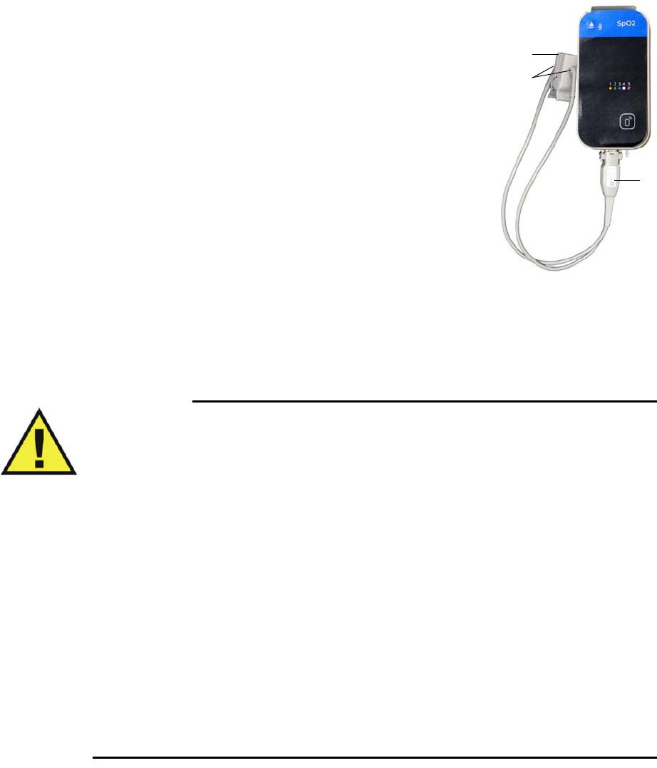
ExpressionMR400InstructionsforUseMonitoringSPO26‐3
Attaching the Clip or Grip to the SpO2 Probe
Toattachaclip(orgrip)totheSpO2probe
CarefullysnapthefiberheadsontheSpO2probeintothe
receptacles(windows)ontheSpO2attachment(cliporgrip).
Eitherfiberheadcanbeinsertedintoeitherwindowonaclipor
grip.
Applying the SpO2 Attachment to the Patient
ReadthewarningsbeforeapplyinganSPO2attachmenttothepatient.
WARNINGS
•General fit: If a clip or grip is too loose, it might compromise the optimal alignment or
dislocate. If the clip or grip is too tight (for example, if the application site is too large
or becomes large due to edema), excessive pressure may be applied resulting in venous
congestion distal from the application site, which could lead to interstitial edema,
hypoxemia, tissue malnutrition, and inaccurate measurements. Skin irritations may
occur as a result of the clip or grip being attached to one location for too long.
Periodically inspect the clip or grip application site and change the application site at
least every 4 hours. Exercise care when using tape to secure the clip or grip, as the
stretch memory properties of most tapes can apply unintended pressure to the site
easily.
• Extremities to avoid: Avoid placing the clip or grip on extremities with an arterial
catheter, intravascular venous infusion line, or inflated blood pressure cuff. Failure to
do so may result in inaccurate readings or false alarm indications.
• Protect the probe from contact with any liquid. If the probe, clips or grips show signs
of damage like exposed fibers, replace the part immediately. Do not use damaged
equipment.
• Keep detached grips and clips away from small children to avoid possibility of
swallowing.
1 SpO2 probe
2 SpO2 attachment (clip shown)
3Fiber heads
1
2
3
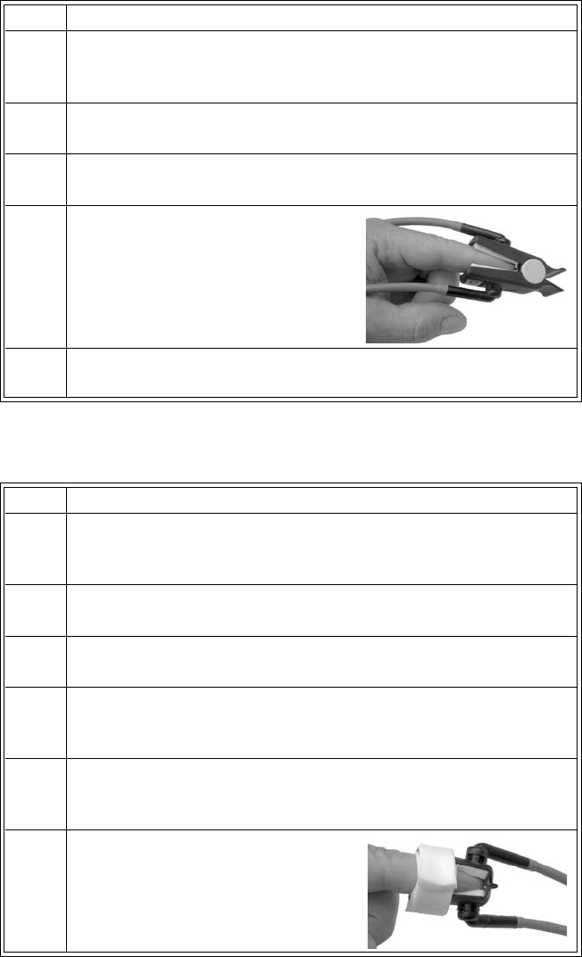
6‐4MonitoringSPO2ExpressionMR400InstructionsforUse
ToapplyareusableSpO2cliptothepatient
ToapplyadisposableSpO2grip(all,exceptneonate)tothepatient
Step Action
1 Selecttheapplicationsite.ItshouldmatchtheSpO2clipsizeso
thattheattachmentdoesnotfallofforapplyexcessivepressureat
thesite.
2Ifpresent,removeanycolorednailpolishfromtheapplicationsite.
3Pressthecliptoopen.
4Pushtheclipoverafingersoeither
fiberheadisonthetopovertheroot
ofthenailandtheotherfiberhead
oppositetoit.
5Ensurethatthefingeristouchingthestopatthecushionandlays
nicelycenteredintheclip.
Step Action
1 Selecttheapplicationsite.ItshouldmatchtheSpO2gripsizeso
thattheattachmentdoesnotfallofforapplyexcessivepressureat
thesite.
2Ifpresent,removeanycolorednailpolishfromtheapplicationsite.
3Liftoffthereleaselinersthatprotecttheadhesive.
4Putthefinger(ortoe)ontoeithersideoftheattachment‐theyare
symmetrical‐suchthatthetipcoversthewindowcompletelyand
doesnotprotrudeoverthehinge.
5Closethegrip.Ifthefitisgood,presstheattachmentfirmlyonthe
fingerortoe.Ifthefitisnotgood,repositiontheattachment.Make
surethelimbiscenterednicelyintheattachment.
6Wrapthefoamwingsaroundthefin‐
gerandattachmentandsticktothe
opposinggripside.Donotstretchthe
foamtoapplyexcessivepressure.
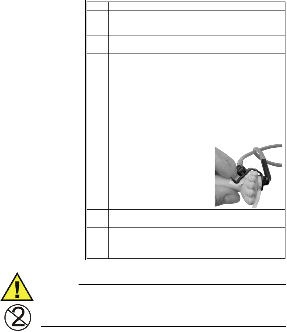
ExpressionMR400InstructionsforUseMonitoringSPO26‐5
ToapplyadisposableneonateSpO2griptothepatient
WARNING
Disposable SpO2 attachments are designed for single patient use and must be disposed after
use. They must not be cleaned and reused. Follow your hospital’s guidelines for appropriate
disposal. Reuse of single-use devices can result in spread of patient infection, degradation of
monitoring performance, or inaccurate measurements.
Step Action
1 Selecttheapplicationsite.ItshouldmatchtheSpO2gripsizeso
thattheattachmentdoesnotfallofforapplyexcessivepressureat
thesite.
2Liftoffthereleaselinersthatprotecttheadhesive.
3 Proceedaccordingtotheapplicationsite:
• Footapplication:Alignthehingeontheoutsidefacingridge
ofthefoot.Makesuretheattachmentisasfaraspossibleto‐
wardthesmalltoebutnotoverit.
•Hand/Wristapplication:Alignthehingeontheoutsidefac‐
ingridgeofthehandorwrist.Youmayhavetoswivelthefi‐
berheadstoanoptimalpositiontoeasetheapplication.
4Withthehingealignedwiththeridgeofthefoot/hand/wrist,press
onesidetotheskinandthenwraptheothersidearoundthelimb
pullingthelongfoampiecegently.
5Pressbothfiberheadsgentlytoattach
theadhesives.
6Securethelongerfoampiecebypressingitfirmlytothefoam/
adhesiveoftheopposingside.
7Ensurethatthetwofiberheadsareopposingandhavegoodskin
contact.Theanglebetweenthetwofiberheadsshouldbeassmall
aspossible,notexceeding45°.Iftheattachmentopenstoomuch,
reattachortryanothersite.
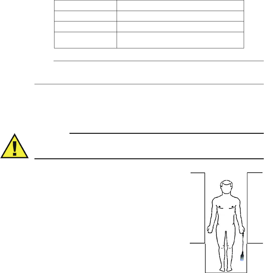
6‐6MonitoringSPO2ExpressionMR400InstructionsforUse
Perfusion Index Value
Whenenabled,thedisplayedperfusionindexvalue(seepage6‐8)isanindicationofthepulsatile
portionoftheSpO2signalcausedbythepatient'sarterialbloodflow.Ifyouneedanindicationof
changeinpulsevolume,useperfusionindexvalue.Thisvaluecanalsobeusedasaquality
indicatoroftheSpO2measurementfromthemodule.Thetablebelowprovidesgeneralguidelines
regardingthisindexvalue.
Note
If a Low Perf alarm is generated, see page 4-32 for corrective actions.
Positioning the wSpO2 Module for Scanning
WARNING
The wSpO2 module must be kept outside the MR system bore or image distortion may
result.
Toensurethebestperformance,specificpositioning
considerationsarerequiredwhenusingthewSpO2modulein
theMRmagnetroom,includingduringharshscansequences
withperipheralnervestimulationlevelsabove80percent.
Whileconsideringthescantobeperformed:
•PlacethewSpO2moduleonornearthepatientandas
closeaspossibletotheboreopening;
• KeeptheSpO2probeandwSpO2moduleoutsidetheMR
systembore;
•PlacethewSpO2moduleonacushionedsurfaceto
minimizeMRvibrations;and,
•CovertheSpO2attachmentsiteonthepatientwith
opaquematerial.
PerfusionIndexValue Meaning
Above1.0 Optimal–highqualityreadings
0.3to1.0 Acceptable–goodqualityreadings
Below0.3 Marginal–Attachmentpositionshouldbeadjusted
oranothersiteshouldbeused.

ExpressionMR400InstructionsforUseMonitoringSPO26‐7
WARNING
If the wSpO2 module is incorrectly positioned when used within the MR magnet room, the
following factors can cause SPO2 waveform distortion and numeric inaccuracies, and
respiration numeric inaccuracies:
• Fast magnetic field changes usually found but not limited to scan sequences using PNS
levels above 80 percent.
• Severe vibrations induced by scan sequences using PNS levels above 80 percent.
• Distance from the bore opening.
• Distance from the bore iso-center in the x, y, or z direction.
ToensurebestperformanceduringSPO2measurements
Step Action
1Ensurethatthefiberheadsaredirectlyoppositeeachother,asthe
lightmustpassthroughthepatient’stissueandbereceivedfor
properoperation.
2Swiveleachfiberheadintoapositionthatcausestheleastbending
ofthecablewhileprovidingthemostcomforttothepatient.
3CheckthebatteryindicatoronthewSpO2moduletoensurethat
enoughchargeexists:
• Greenbatteryindicator=Chargesufficient;proceedtostep5.
•Redbatteryindicator=Chargelow;proceedtostep4.
Seepage2‐11fordetails.(Also,youcanreferencethestatus
informationpane;seepage2‐16.)
4InsertachargedmodulebatteryintothewSpO2moduleandthen
recheckthebatteryindicatortoensureasufficientchargebefore
proceeding;seepage1‐26.
5CheckthenetworkchannelindicatoronthewSpO2moduleto
ensurecommunicationisestablishedwiththeMR400:
• Steady=Goodcommunication;proceedtostep7.
• Flashing=Nocommunication;proceedtostep6.
Seepage2‐11fordetails.(Also,youcanreferencethestatus
informationpane;seepage2‐16.)
6EnsurethatthewSpO2moduleiswithin9.1m(30feet)ofthe
MR400,inthesameMRIroomorinthesameshieldedroom,andis
settothesamewirelessnetworkchannelusedbytheMR400;see
page1‐29.
7ChecktheperfusionindexvalueforthequalityoftheSpO2
measurementfromthemodule;seepage6‐6fordetails.
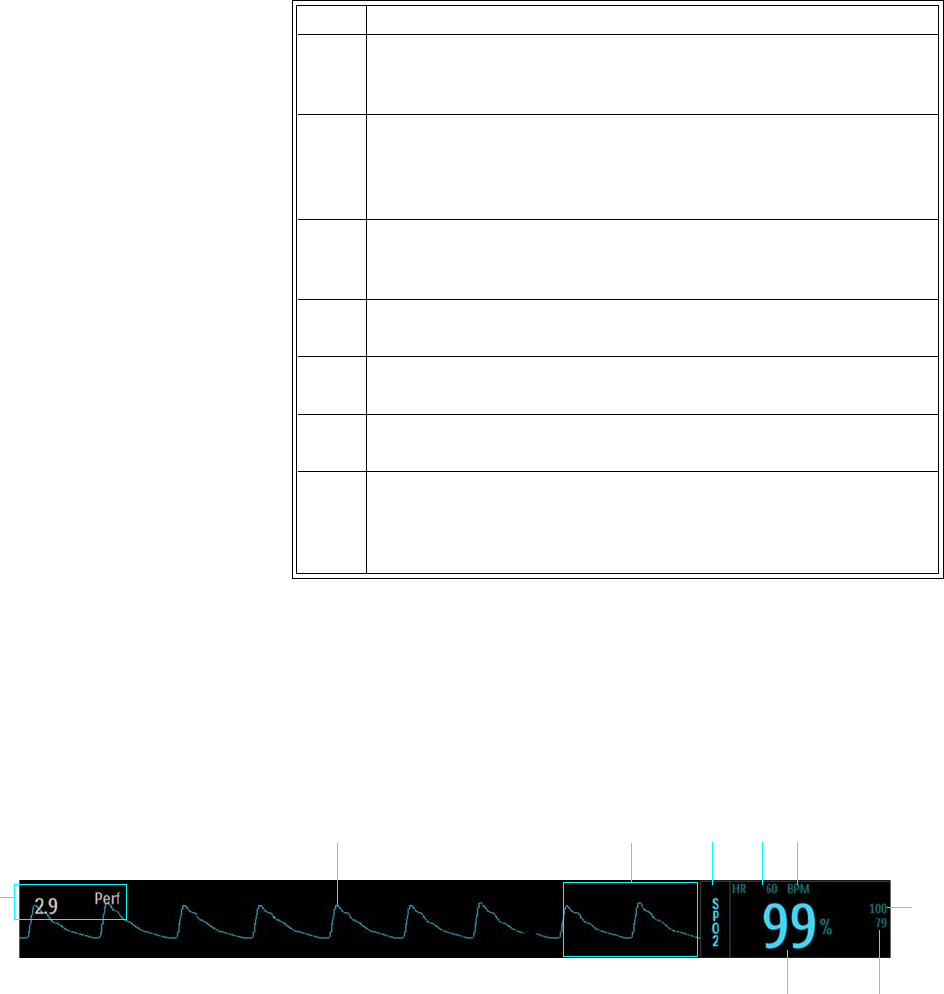
6‐8MonitoringSPO2ExpressionMR400InstructionsforUse
SPO2 Waveform and VS Box
TheSpO2measurementsaredisplayedasawaveformintheVStraceareaofthescreenandas
numericinformationintheSPO2VSbox.Otherdata,includingSpO2‐relatedalarminformation,
arealsoprovidedinthisareaofthescreen,asdetailedbelow.
8 SelectthePatientType.
SeeSelectingthePatientTypeonpage3‐11.
9CheckforanydisplayedSPO2messages
Ifamessageispresent,followtherecommendedactiontoachieve
betterresults(seepage4‐26).
10 Placethemoduleascloseaspossibletotheboreopening.(Ifthe
modulecanbeplacedoutsidethebore,positioningattheiso‐
centerisnotnecessary.)
11 KeeptheSpO2probeandmoduleoutsidetheMRsystembore.
12 Placethemoduleonacushionedsurface.
13 CoverthepatientSpO2attachmentsitewithopaquematerial.
14 Duringmeasurement,checkthepatienttoensurethatthe
applicationsitehasapulsatileflowandthatthesitehasnot
changedinthickness(forexample,duetoedema)causingan
improperfit.
Step Action
1
6
234
9
8
5
7

ExpressionMR400InstructionsforUseMonitoringSPO26‐9
Assessing Suspicious SPO2 Readings
Pulseoximetrymeasurementsarestatisticallydistributed.Withneweralgorithms,suchasFAST‐
SPO2,thecalculationofSPO2isnotdirectlylinkedtothecorrectdetectionofeachpulse.When
thepulserateisveryloworastrongarrhythmiaispresent,theSPO2/plethysmographypulse
ratemaydifferfromtheheartratecalculatedfromECG.Thisdoesnotindicateaninaccurate
SPO2value.IfyoudoubtthemeasuredSPO2,usetheplethysmographywavetoassessthesignal
quality.
WARNING
Always shield (for example, cover with opaque material) the SPO2 clip or grip from
extraneous incidental light sources, as such light can cause erroneous SPO2 readings or
pulse detection errors.
Item Name Definition
1 SpO2 VS waveform Is the detected SpO2 (pleth) pulsatile waveform (Trace C), automatically adjusted for
proper viewing if above a minimum level
Note
To change the waveform speed, see Sweep Speed on page 3-25.
2 Alarm flag area Displays SPO2 alarm flags when detected; see page 4-31.
3SPO2 VS box label Indicates the SpO2 vital sign parameter, and accesses the SPO2 menu
4 Heart rate numeric Is the patient’s detected heart rate measurement
5 Unit of measure Indicates that the heart rate numeric is given in BPM (beats per minute)
6 SpO2 upper alarm limit Is the upper limit setting for the SpO2 alarm, and accesses the SPO2 Alarm Limits
menu
7 SpO2 lower alarm limit Is the lower limit setting for the SpO2 alarm, and accesses the SPO2 Alarm Limits
menu
8 SpO2 numeric Is the patient’s detected arterial oxygen saturation measurement, given as a percentage
9 Perfusion index Is the value for the portion of the measured signal caused by the pulsating arterial
blood flow, which can be used as a measurement quality indicator; see page 6-15

6‐10MonitoringSPO2ExpressionMR400InstructionsforUse
WARNINGS
• SPO2 monitoring requires the detection of valid pulses to correctly determine SPO2
and heart rate values. Any of the following items can lead to inaccuracies of the SPO2
readings and/or prolonged measurement time: Ambient light (including photodynamic
therapy), physical movement (patient and imposed motion), arrhythmias and/or
erratic heartbeats, diagnostic testing, electromagnetic interference, electrosurgical
units, dysfunctional hemoglobin, intravascular dyes, presence of dyes or pigments at
the application site, and inappropriate positioning of the pulse oximeter attachment. If
questionable readings are obtained, check the patient’s vital signs by alternate means
before administering medication.
•Attachment movement, ambient light (especially strobe or flashing lights) or
electromagnetic interference can give unexpected intermittent readings when the
probe is not attached to a patient. Bandage and grip attachment designs are
particularly sensitive to minimal movement that might occur when the probe is
dangling, not attached to the patient. An unapplied probe may cause readings to be
displayed on the monitor. To avoid misdiagnosis, ensure the probe is applied to patient
correctly.
Changing the SPO2 Waveform Amplitude
TheverticalscaleofthedisplayedSPO2waveformcanbechangedtobestsuittheviewing
requirements.
TochangetheSPO2waveformamplitude
Step Action
1 SelecttheSPO2VSbox.
TheSPO2menuappears.Currentsettingsaredisplayed.
2 SelectSize.
TheSizemenuappears.Thecurrentsettingishighlighted.
3 Selectthedesiredsize:
10%
20%
40%
60%
80%
100%
Thesettingischanged.
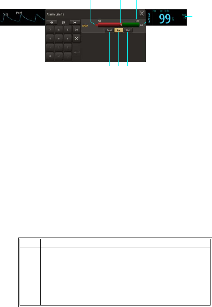
ExpressionMR400InstructionsforUseMonitoringSPO26‐11
Changing the SPO2 Alarm Limits
TheSPO2AlarmLimitsmenucanbeaccessedbytouchingthealarmlimitsettingsintheSPO2VS
box.
TochangetheSPO2alarmlimitsettings
1Alarm limit settings, SPO2 VS box
2High button
3Low button
4Desat button
5SPO2 Alarm Limits menu label
6Enter button
7Current adjustment
8Desat alarm setting
9Alarm limit, minimum
10 Lower alarm limit setting
11 Upper alarm limit setting
12 Alarm limit, maximum
Step Action
1 SelectthealarmlimitsettingsintheSPO2VSbox.
TheSPO2AlarmLimitsmenuappears.Currentsettingsare
displayed.
2 SelecttheLow,High,orDesatbutton.
Theselectedbuttonwillbehighlightedandthecurrentadjustment
willbedisplayed.(Desatmustbeon;seepage6‐15.)
1
2
7
3456
1098 1211
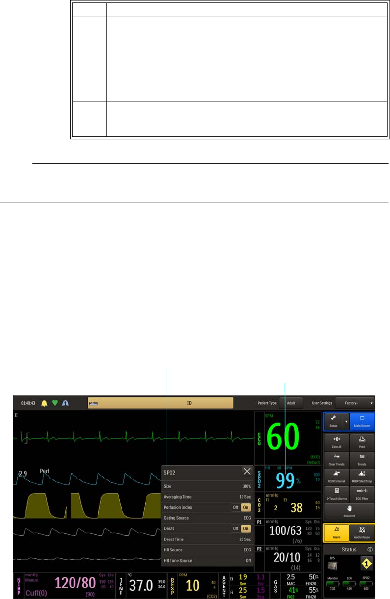
6‐12MonitoringSPO2ExpressionMR400InstructionsforUse
Note
See chapter 4 for detailed alarm limit setting instructions and options.
SPO2 Menu
SPO2menuitemsallowyoutocontrolSPO2functionsandsettings.
ToopentheSPO2menu
SelecttheSPO2VSbox.
3Usingthekeypad,ortheincrement,decrement,orOffbuttons,
enterthedesiredsetting.
Thecurrentadjustmentwillreflectthesetting.
4PresstheEnterbuttontosavethesetting.
Thealarmlimitsettingisupdated.
5Tochangeotherlimitsettings,repeatsteps2,3,and4.
Thecurrentadjustmentwillreflectthechange.
Step Action
SPO2 VS box
SPO2 menu
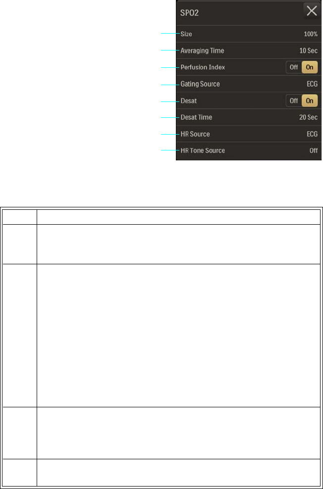
ExpressionMR400InstructionsforUseMonitoringSPO26‐13
ThefollowingSPO2menuitemsareavailable:
TochangesettingsintheSPO2menu
Size
ChangestheverticalscaleoftheSPO2(pleth)waveformsothathighamplitudescanbescaled
downtoavoidclippingofthepeaksandlowamplitudescanbescaleduptoviewthepeaks.
Thefollowingoptionsareavailable:
1Size
2Averaging Time
3 Perfusion Index
4Gating Source
5Desat
6Desat Time
7HR Source
8 HR Tone Source
Step Action
1 SelecttheSPO2VSbox.
TheSPO2menuappears.Currentsettingsaredisplayed.
2TouchthemenuitemtoselectoneofthefollowingSPO2options:
Size
AveragingTime
PerfusionIndex
GatingSource
Desat
DesatTime
HRSource
HRToneSource
Themenuitemappears.Thecurrentsettingishighlighted.
3 Selectthedesiredsettingfromthemenuoptions(exceptPerfusion
IndexandDesat,whichareselectableontheSPO2menu).
Thesettingisentered.
4Tochangeothersettings,repeatsteps2and3.
2
3
4
1
5
6
7
8

6‐14MonitoringSPO2ExpressionMR400InstructionsforUse
•10%
•20%
•40%
•60%
•80%
•100%(Default)
ToadjustthesizeoftheSPO2waveform
SeeChangingtheSPO2WaveformAmplitudeonpage6‐10.
Averaging Time
Selectshowquicklythereadingrespondstochangesinthepatient’ssaturation,whereselecting
alongerdurationwillpreventthesaturationvaluefromchangingquicklywhichcanbeusefulfor
avoidingalarmtriggeringinpatientswithverydynamicconditionssuchasneonataland
pediatrics.
Thefollowingoptions(inseconds)areavailable:
•5Sec
•10Sec(Default)
•15Sec
TosettheaveragingtimeoftheSPO2reading
Step Action
1 SelecttheSPO2VSbox.
TheSPO2menuappears.Currentsettingsaredisplayed.
2 SelectAveragingTime.
TheAveragingTimemenuappears.Thecurrentsettingis
highlighted.
3 Selectthedesiredtimeforaveraging:
5Sec
10Sec
15Sec
Thesettingischanged.

ExpressionMR400InstructionsforUseMonitoringSPO26‐15
Perfusion Index
Controlstheperfusionindexvalueindicationandalarmfunction(seepage5‐6).Thefollowing
optionsareavailable:
•Offdisablestheperfusionindexfunctions.
•Onenablestheperfusionindexfunctions.(Default)
Tocontroltheperfusionindexfunctions
Gating Source
SetsthecardiacgatingsourcebasedonameasuredsignalthatisusedforMRsystemtriggering.
(ThisisthesameoptionasintheECGmenu.)
Thefollowingoptionsareavailable:
•ECGoutputsasignalthatrepresentsthedetectionoftheR‐peakofaQRScomplex.
(Default)
•Pulseoutputsasignalthatrepresentsthedetectionofthepeakoftheperipheralpulse
complex.
Tosetthegatingsource
SeeAppendixDfordetails.
Desat
ControlsthedesaturationalarmandallowsadjustmentoftheDesatalarmsetting(seepage6‐
11),whereaDesatalarmwillbedeclaredwhenthedetectedoxygenationconditionhas
remainedatorbelowthevaluefortheperiodestablishedbytheDesatTimesetting(seepage6‐
16).
Thefollowingoptionsareavailable:
•Offdisablesthedesatalarmfunction.
Step Action
1 SelecttheSPO2VSbox.
TheSPO2menuappears.Currentsettingsaredisplayed.
2LocatePerfusionIndexandselectthedesiredsetting:
Off
On
Thesettingisentered.

6‐16MonitoringSPO2ExpressionMR400InstructionsforUse
•Onenablesthedesatalarmfunction.(Default)
Tocontrolthedesatalarmfunction
Desat Time
WhenDesatison,thissetsthetimethatmustpassbeforedeclaringthatadesaturation
conditionexists.
Thefollowingoptions(inseconds)areavailable:
•20Sec(Default)
•25Sec
•30Sec
•35Sec
•40Sec
Tosetthedesattime
Step Action
1 SelecttheSPO2VSbox.
TheSPO2menuappears.Currentsettingsaredisplayed.
2Locate
Desatandselectthedesiredsetting:
Off
On
Thesettingisentered.
Step Action
1EnsurethatDesatisOn.SelecttheSPO2VSbox.
TheSPO2menuappears.Currentsettingsaredisplayed.(Seepage
6‐15fordetails.)

ExpressionMR400InstructionsforUseMonitoringSPO26‐17
HR Source
Selectsthesourcethatproducestheheartrate,asdisplayedintheECGandSPO2VSboxes
(identicaltoandinteractivewithsameoptionintheECG,P1andP2menus).
Thefollowingoptionsareavailable:
•Autosetsthesourceautomaticallyaccordingtothehighestpriorityactiveinputthatisfirst
toreportvalidpatientdata.Thepriorityranking(highesttolowest)isECG,P1,P2,SPO2
(providedthattheP1andP2channelshavebeenlabeledABP;seeSetLabelonpage8‐24
fordetails).Thesourcewillbecomeunavailablewhenithasproducednovaliddatafora
periodoften(10)ormoreseconds.Thesystemexaminesthehighestpriorityactiveinput.
Ifnotfound,thesecond‐highestpriorityinputischosen,etcetera.Ifnonearepresent,
thenNoneisdisplayedastheheartratemeasurementnumeric.
•ECGsetsECGasthesource.(Default)
•ABPsetsABPasthesource(ifnopressurechannelislabeledABP,awarningboxwillallow
automaticrenamingandselectionbeforeproceeding;alsoseeSetLabelonpage8‐24).
•SPO2setsSPO2asthesource.
Tosettheheartratesource
2 SelectDesatTime.
TheDesatTimemenuappears.Thecurrentsettingishighlighted.
3 Selectthedesiredtime(inseconds)forthealarmindication:
20Sec
25Sec
30Sec
35Sec
40Sec
Thesettingischanged.
Step Action
1 SelecttheSPO2VSbox.
TheSPO2menuappears.Currentsettingsaredisplayed.
2 SelectHRSource.
TheHRSourcemenuappears.Thecurrentsettingishighlighted.
Step Action

6‐18MonitoringSPO2ExpressionMR400InstructionsforUse
HR Tone Source
Setsthesourceusedfortheheartratetone(identicaltoandinteractivewithsameoptioninthe
intheMonitorSetup>SoundAdjustmenuandintheECGmenu).
Thefollowingoptionsareavailable:
•Offremovestheheartbeatdetectedsymbolfromthedisplayandnopulsetonewillbe
sounded.(Default)
•QRSprovidestheheartbeatdetectedsymbolandatonetriggeredbytheQRSdetection
fromtheECGvitalsign.
•SPO2providestheheartbeatdetectedsymbolandatonemodulatedbytheSPO2vital
sign,wherethelowertheSPO2value,thelowerthepitch.
Tocontroltheheartratetonesource
3 Selectthedesiredsettingfortheheartratesource:
Auto
ECG
ABP
SPO2
Thesourceischanged.
Step Action
1 SelecttheSPO2VSbox.
TheSPO2menuappears.Currentsettingsaredisplayed.
2 SelectHRToneSource.
TheHRToneSourcemenuappears.Thecurrentsettingis
highlighted.
3 Selectthedesiredsettingforthetonesource:
Off
QRS
SPO2
Thesettingischanged.
Step Action

ExpressionMR400InstructionsforUse MonitoringCO2(LoFloOption)7‐1
CHAPTER 7
Monitoring CO2 (LoFlo Option)
WhenequippedwiththeLoFloCO2option,thepatient’sairwayrespiratorygascanbe
monitored.Thesystemusessidestreammeasurementstoproduce:
•AfractionalinspiredCO2(FiCO2)value(thelowestreadingoftheCO2waveforminthe
previous20seconds)andanend‐tidalCO2(EtCO2)valuemeasuredduringexpiration.
•Arespirationrate:Thenumberofbreathsperminute.
•Awaveformoftheconcentrationofcarbondioxideintherespiratorygases.
WARNINGS
•Do not use on patients that cannot tolerate the withdrawal of 50ml/min ± 10 ml/min
from the airway or patients that cannot tolerate the added dead space to the airway.
• An alarm will sound when the MR400 is too close to the MR magnet and shutdown of
CO2 monitoring will occur. Always position the MR400 as indicated on page 3-2.
Note
LoFlo option-equipped models do not feature a water trap (see page 7-4). If your MR400 is
equipped with a water trap, refer to chapter 9 for CO2 monitoring instructions.
MR400 Preparation for CO2 Monitoring
WhenpreparingtheMR400forCO2monitoring,ensurethatthewastegasport(seepage1‐19)
hasbeenconnectedtoyourfacility’sgasscavengingsystemfordisposalofsampledand
calibrationgases.
Note
Never route the waste gas tubing in a location that will allow it to be an obstruction or stepped on.
7‐2MonitoringCO2(LoFloOption) ExpressionMR400InstructionsforUse
Operation and Use
Whenmonitoringanestheticagentgases,thetypicaloperationsandpossibleconditionsthatcan
arisemayresultinpotentialmessagesrequiringyourattention.Seepage4‐26foramessage
listingandsuggestedactions.
Warm-Up Period
Inordertoachieveaccurateidentificationsandmeasurements,theLoFlosystemrequiresa
warm‐upperiodtothermallystabilize.Thiswarm‐upperiodbeginswhentheCO2parameteris
activated.Uponactivation,CO2WarmingUpwillbedisplayeduntiltheLoFlosystembecomes
fullyoperational(about2minutes).
Zero Reference Adjustment
WARNING
During Zero calibration the system pulls ambient air through the zero intake port on the
cart The calibration system assumes that the ambient air will contain normal trace amounts
of CO2. If the system is placed in an unventilated area that allows CO2 (from the waste gas
port on the rear panel, if not connected to a gas scavenging system) to accumulate, the result
could be inaccurate CO2 zeroing and resulting inaccurate patient readings. Always place the
cart in a well ventilated area.
TheLoFlosystemwilloccasionallyperformazeroreferenceadjustment(ZeroCal)toensurethe
accuracyofthedisplayedgasconcentrations.PerformingCO2Zerowillbedisplayedduringazero
referenceadjustment;allowtheprocesstocomplete.Themaximumtimerequiredforcalibrationis
approximately40seconds.ZeroCalisnotrequiredwhenswitchingsamplinglines.
Undercertainconditions,ZeroCalwillnotbeallowed:
•Iflessthan20secondshavepassedsincedetectionofthelastbreath;
•IftheCO2temperatureisunstable;or
•IfthesamplinglineisdisconnectedfromtheCO2port.
Toperformamanualzeroreferenceadjustment
Step Action
1IfCO2WarmingUpisdisplayed,waitasthesystemthermally
stabilizes.Whenthemessageiscleared,proceed.
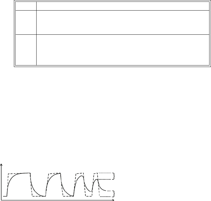
ExpressionMR400InstructionsforUse MonitoringCO2(LoFloOption)7‐3
Breath Rate Distortion
Theeffectofrisetimedistortiontothegascurvebecomesapparentwhenthebreathingrate
increasessothatthetimeforafullinspiratoryorexpiratoryeventgetsshorter.Inthose
situations,duetotheeffectoftherisetime,thegascurvedoesnotreachthetrueend‐tidal(or
firstinspiredvalue)andtheend‐tidalgasvaluemaythenbeunderestimated.Correspondingly,
thefirstinspiredvaluemaybeoverestimated.Belowisanexaggeratedillustrationoftheeffect.
Thebreathratelimitforaccuratelyresolvedend‐tidalgasvalues(atanI:Eratioof1:1)maybe
foundinAppendixA.TheeffectofotherI:Eratiosmaybecalculatedbydeterminingthelengthof
theshortestinspiratory/expiratoryeventthatcanberesolvedaccurately:
tresolved=60/(2xBRlimit(1:1)
BRlimit(I:E)=60/((I+E)xtresolved)
Thedifferenceintheseresultswhencomparedtotherisetime'sspecificationisthatrisetime's
onlytests10‐90%performance.Thisspecificationisfor(0+accuracy)to(100‐accuracy)%andis
thusmuchtougher.Theabilitytoproperlyresolveend‐tidalvaluescanbemeasuredbyusingthe
set‐updescribedinISO80601‐2‐55:2011figure201.101.Inshort,themethodconsistsof
samplinggasfromtwodifferentsourcesconnectedtoanelectricallycontrolledpneumaticvalve
topermitrapidswitchingbetweenthetwosources.Duringthetest,thevalveissettoswitchgas
sourceatanumberoffrequencies(simulatingtherangeofspecifiedbreathrates)andforeach
frequencytheend‐tidalvaluepresentedbythegasanalyzerisnoted.Fromadiagramofend‐tidal
valueoverfrequency,thefrequencyatwhichthegasanalyzerisnolongerabletoresolveend‐
tidalvaluesaccordingtospecificationisidentified.Thisabilitytoproperlyresolveend‐tidalvalues
islistedinthespecification.
2 SelecttheCO2VSbox.
TheCO2menuappears.Currentsettingsaredisplayed.
3 SelectZeroCal.
CalibrationwillbeginandPerformingCO2Zerowillbedisplayed.
Whencomplete,themessagewillberemoved.
Step Action
Fi error
Percent
Time
Et error
- - at gas sampling site
— as presented by gas analyzer
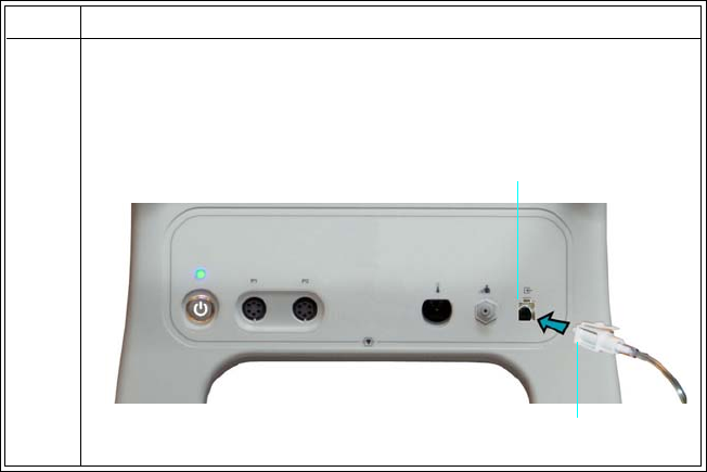
7‐4MonitoringCO2(LoFloOption) ExpressionMR400InstructionsforUse
Patient Preparation for CO2 Monitoring
Whenpreparingapatient,theaccessorypositiononthepatientwillimpacttheperformanceand
operationoftheCO2parameter.
Selecting the CO2 Accessory
Inpatientsonabreathingcircuit,asampleoftherespiratorygasisdrawnfromthepatient’s
breathingcircuitthroughanairwayadapterandagassamplingline.Inpatientswhoarenotona
breathingcircuit,thegassampleisdrawnthroughanasalcannula.Thesespeciallydesigned
cannulasandon‐airwayadaptersincorporateafilterandsamplecelltoprovidemaximum
filtrationoffluidsandcontaminantstoprotectagainstsystemintake.WhenselectingCO2
accessories(seepage1‐34foralisting),considerthefollowing:
•Thetypeofpatient(adult,pediatric,orneonatal)
•Whetherthepatientisreceivingsupplementaloxygen
•Theconditionofthepatient
•Allaccessoriesaresingleuse.
Connecting the Sampling Line
Toconnectthesamplingline
Step Action
1InsertthesamplinglineconnectorintotheCO2portonthepatient
connectionpanelandthenpushtheconnectorforwarduntilyou
feelorhearitclickintoplace.
Sampling line connector
CO2 port
ExpressionMR400InstructionsforUse MonitoringCO2(LoFloOption)7‐5
WARNINGS
•Inspect CO2 port and accessories before use. If the sampling line, connector or port
show signs of damage, replace the part immediately or discontinue use and contact
technical support. Never use damaged equipment.
• Frequently inspect the patient sampling line and keep it clear of any moving
mechanisms (for example, table wheels) which could cut, pinch, or dislodge the
sampling line. Leaks, reduced or stopped flow, or internal venting of sampled gas into
damaged tubing will cause inaccurate measurements.
• Do not position the sampling line in any manner that may cause entanglement or
strangulation.
• Replace the sampling line if excessive secretions are observed, as inaccurate
measurements could result if the flow is reduced or stopped.
• Leakages in the breathing system or sampling system may cause the displayed EtCO2
values to be too low. Always connect all components securely and check for leaks
according to standard clinical procedures. Displacement of the sampling line cannula
or airway adapter can cause lower than actual EtCO2 readings.
• If CO2 values for patients who are not on a breathing circuit appear extremely low,
check whether the patient is breathing through the mouth or whether one nostril is
blocked.
Notes
• For optimum fit and compatibility, use only specified parts.
• Always inspect the patient sampling line after attachment to the MR400.
2IfCO2WarmingUpisdisplayed,waitasthesystemthermally
stabilizes(about2minutes).Whenthemessageiscleared,
proceed.
3AlwaysremovethepatientsamplinglinefromtheCO2portwhen
notinuse.(Toremovethesamplingline,pressdownonthelocking
tabandpulltheconnectorfromtheport.)
Note
To increase the life of the filter and pump, when CO2 will not be
used to monitor a patient, we recommend turning the CO2
parameter off; see Parameters on page 3-18.
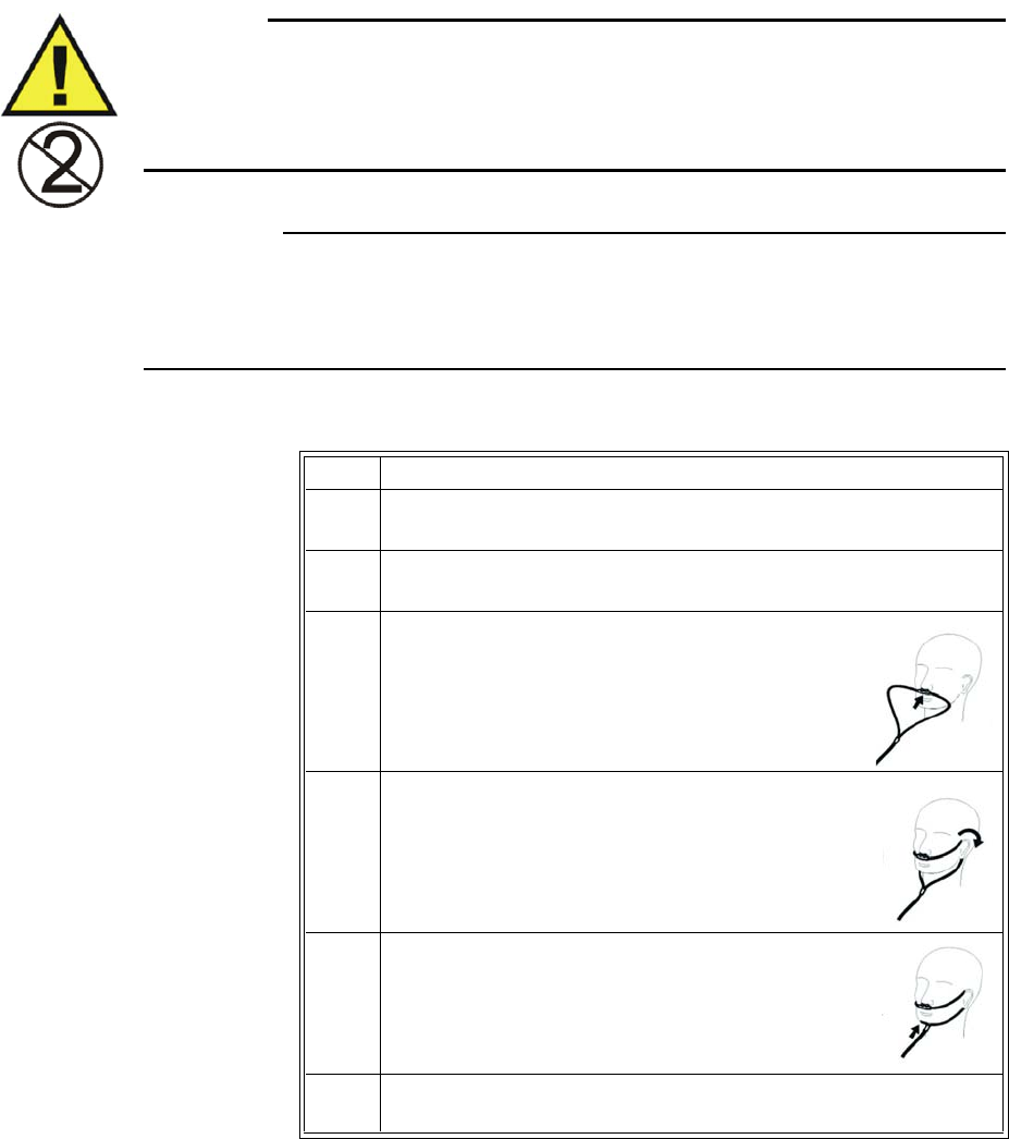
7‐6MonitoringCO2(LoFloOption) ExpressionMR400InstructionsforUse
Applying the Sampling Line to the Patient
Selectthepatientsamplinglinethatisappropriateforthepatientsizeandapplication.Patient
samplinglineswiththeairwayadapterareintendedforusewithbreathingcircuitsand
anesthesiacircuitsthathaveanintegratedairwayadapter.
WARNING
Patient sampling lines are intended for single-patient use only. Do not clean or disinfect these
items. Follow your hospital’s guidelines for appropriate disposal. Reuse of single-use devices
can result in spread of patient infection, degradation of monitoring performance, or
inaccurate measurements.
CAUTIONS
• The accuracy of the data is greatly influenced by the proper use and fitting of the patient
sampling line to ensure proper sampling without the introduction of outside air.
• Remove the patient sampling line from the CO2 port when not in use.
Toapplythesamplinglinetothepatient
Step Action
1Ensurethatthesamplinglineisclean,dryandundamaged.Replace
thelineifnecessary.
2InsertthesamplinglineconnectorintotheCO2port(seepage7‐4).
Aclickwillbeheardwhenproperlyinserted.
3 Positionthecannulaonthepatient’sfaceby
insertingthenasalprongsintothenostrils.
4Passthetubingovertheearsandbehindthehead,
ensuringthepatient’sheadwillnotrestonanypart
ofthecannulawhilethepatientislyingdown.
5Slidethesleevetowardthepatient’sheadtoassurea
goodfitofthecannula.
6Ifusingthesamplinglinewiththeairwayadapter,proceedtostep
7;otherwisegotostep8.

ExpressionMR400InstructionsforUse MonitoringCO2(LoFloOption)7‐7
CO2 Waveform and VS Box
TheCO2measurementisdisplayedasawaveformintheVStraceareaofthescreenandas
numericinformationintheCO2VSbox.Otherdata,includingCO2‐relatedalarminformation,are
7Placetheairwayadapterattheproximalendoftheairwaycircuit.
CAUTION
Always insert the patient sampling line into the CO2 port before
inserting the airway adapter into the breathing circuit. Failure to
follow this may introduce a leak in the circuit, thereby reducing set
minute volume.
Note
Do not place the airway adapter between the ET tube and the elbow
as this may allow patient secretions to accumulate in the adapter. If
pooling does occur, replace the airway adapter. To prevent moisture
from draining into the airway adapter, always place the adapter
tubing in a up position, as shown above.
8 SelectthePatientType.
SeeSelectingthePatientTypeonpage3‐11.
9Checkthattheconnectionshavebeenmadecorrectlybyverifying
thepatient’sbreathingeffortswiththedisplayedwaveform.
WARNING
Before completion of patient setup, ensure that the
patient’s breathing efforts coincide with the displayed
CO2 waveform.
10 Ifthefollowingwarningisdisplayed:
PersistentCO2occlusiondetected.
PleaseclearocclusionandpressOK
toresumeusingCO2
Clearanypinchesorobstructionsinthesamplinglinebefore
proceeding.
Step Action
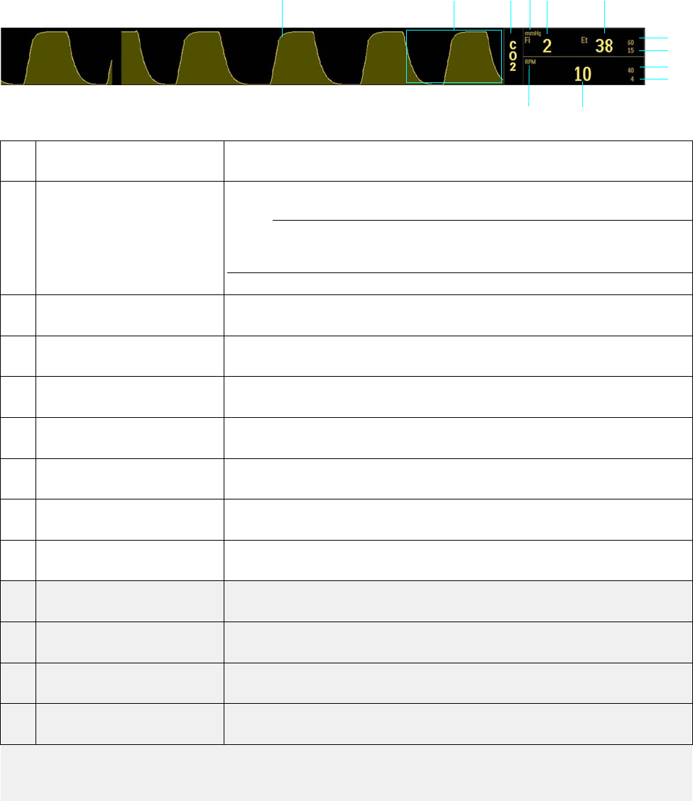
7‐8MonitoringCO2(LoFloOption) ExpressionMR400InstructionsforUse
alsoprovidedinthisareaofthescreen.(CO2[RESP]informationcanbedisplayedintheCO2VS
boxorintheRESPVSbox,asdetailedbelow.)
Item Name Definition
1 CO2 VS waveform Is the detected CO2 waveform (Trace D)
Note
To change the waveform speed, see Resp Speed on page 3-25.
2 Alarm flag area Displays CO2 alarm flags when detected; see page 4-31.
3CO2 VS box label Indicates the CO2 vital sign parameter, and accesses the CO2 menu
4 Unit of measure Indicates that the gas measurement numeric values are given in mmHg
(millimeters of mercury) or kPa (kilopascals); see page 7-11.
5 FiCO2 numeric Is the patient’s detected fractional inspired CO2 measurement
6 EtCO2 numeric Is the patient’s detected end-tidal CO2 measurement
7 EtCO2 upper alarm limit Is the upper limit setting for the end-tidal CO2 alarm, and accesses the CO2
(Et) Alarm Limits menu
8 EtCO2 lower alarm limit Is the lower limit setting for the end-tidal CO2 alarm, and accesses the CO2
(Et) Alarm Limits menu
9Respiration rate upper alarm
limit
Is the upper limit setting for CO2-derived respiration rate alarm, and accesses
the CO2 (RESP) Alarm Limits menu
10 Respiration rate lower alarm
limit
Is the lower limit setting for CO2-derived respiration rate alarm, and accesses
the CO2 (RESP) Alarm Limits menu
11 Respiration rate numeric Is the patient’s detected respiration rate measurement, as derived from CO2
12 Unit of measure Indicates that the respiration rate numeric is given in RPM (respirations per
minute)
When Source is set to BEL in the RESP menu (see page 10-5), the CO2 VS box will also contain CO2-derived respiration rate
elements, as indicated by the shaded rows and illustration above; otherwise, this information will be displayed in the RESP VS box
(see page 7-10).
7
13456
11
8
9
10
2
12
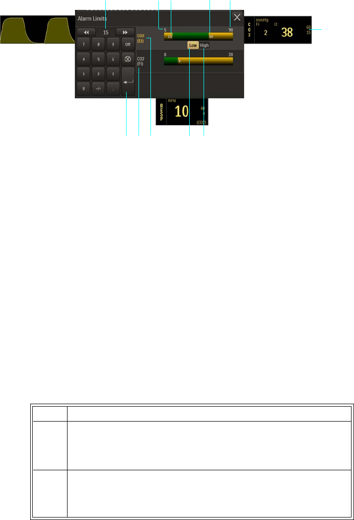
ExpressionMR400InstructionsforUse MonitoringCO2(LoFloOption)7‐9
Changing the CO2 and CO2 (RESP) Alarm Limits
TheCO2(Et)andCO2(Fi)AlarmLimitsmenucanbeaccessedbytouchingthealarmlimitsettings
intheCO2VSbox.
TochangetheCO2(Et)andCO2(Fi)alarmlimitsettings
1Alarm limit settings, CO2 (Et), CO2 VS box
2High button
3Low button
4CO2 (Et) Alarm Limits menu label (active adjustment shown)
5CO2 (Fi) Alarm Limits menu label
6Enter button
7Current adjustment
8Alarm limit, minimum
9Lower alarm limit setting
10 Upper alarm limit setting
11 Alarm limit, maximum
Step Action
1 Selectthe(Et)CO2alarmlimitsettingsintheCO2VSbox.
TheCO2AlarmLimitsmenuappears.CurrentCO2(Et)settingsare
displayed.
2 SelecttheCO2alarmlimitsmenu,CO2(Et)orCO2(Fi),thatyou
wanttochange.
Theassociatedmenuappears.Currentsettingsaredisplayed.
1
2
7
3456
8 9 10 11
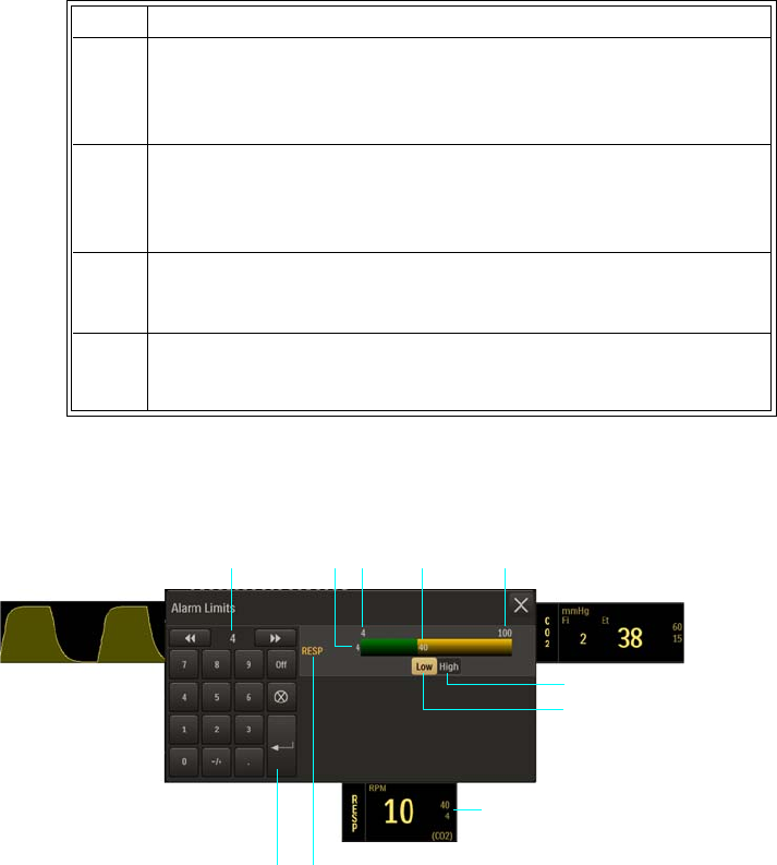
7‐10MonitoringCO2(LoFloOption) ExpressionMR400InstructionsforUse
Atthedefaultsetting,theCO2(RESP)AlarmLimitsmenucanbeaccessedbytouchingthealarm
limitsettingsintheRESPVSbox.
3 SelecttheLowbuttonortheHighbutton.
Theselectedbuttonwillbehighlightedandthecurrentadjustment
willbedisplayed.
4Usingthekeypad,ortheincrement,decrement,orOffbuttons,
enterthedesiredsetting.
Thecurrentadjustmentwillreflectthesetting.
5PresstheEnterbuttontosavethesetting.
Thealarmlimitsettingisupdated.
6
Tochangetheremainingsettings,repeatsteps2–5.
Thecurrentadjustmentwillreflectthechange.
1High button
2Low button
3Alarm limit settings, CO2 (RESP), RESP VS box
4CO2 (RESP) Alarm Limits menu label
5Enter button
6Current adjustment
7Lower alarm limit setting
8Alarm limit, minimum
9Upper alarm limit setting
10 Alarm limit, maximum
Step Action
1
2
6
3
45
7 8 9 10

ExpressionMR400InstructionsforUse MonitoringCO2(LoFloOption)7‐11
TochangetheCO2(RESP)alarmlimitsettings
Note
See chapter 4 for detailed alarm limit setting instructions and options.
Changing the Unit of Measure
Tochangetheunitofmeasure
Step Action
1 SelecttheCO2(RESP)alarmlimitsettingsintheRESPVSbox(or,in
theCO2VSbox,seepage7‐7.)
TheCO2(RESP)AlarmLimitsmenuappears.Currentsettingsare
displayed.
2 SelecttheLowbuttonortheHighbutton.
Theselectedbuttonwillbehighlightedandthecurrentadjustment
willbedisplayed.
3Usingthekeypad,ortheincrement,decrement,orOffbuttons,
enterthedesiredsetting.
Thecurrentadjustmentwillreflectthesetting.
4PresstheEnterbuttontosavethesetting.
Thealarmlimitsettingisupdated.
5
Tochangetheremainingsetting,repeatsteps2,3,and4.
Thecurrentadjustmentwillreflectthechange.
Step Action
1PresstheSetupkeyandthentheMonitorkey.
TheMonitorSetupmenuappears.Currentsettingsaredisplayed.
2OntheMonitorSetupmenu,selectService(Bio‐Med).
TheService(Bio‐Med)sub‐menuappears.
3OntheService(Bio‐Med)menu,selectSystemConfig.
TheSystemConfigmenuappears.Currentsettingsaredisplayed.
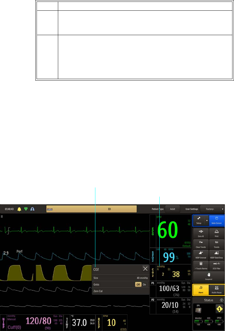
7‐12MonitoringCO2(LoFloOption) ExpressionMR400InstructionsforUse
CO2 Menu
TheCO2menuallowsyoutocontroltheCO2andCO2(RESP)monitoringfunctionsandsettings.
ToopentheCO2menu
SelecttheCO2VSbox.
4OntheSystemConfigmenu,selectGasUnits.
TheGasUnitsmenuappears.Thecurrentsettingishighlighted.
5 Selectthedesiredunitofmeasure:
mmHg
kPa
Thesettingischanged.
Step Action
CO2 VS box
CO2 menu
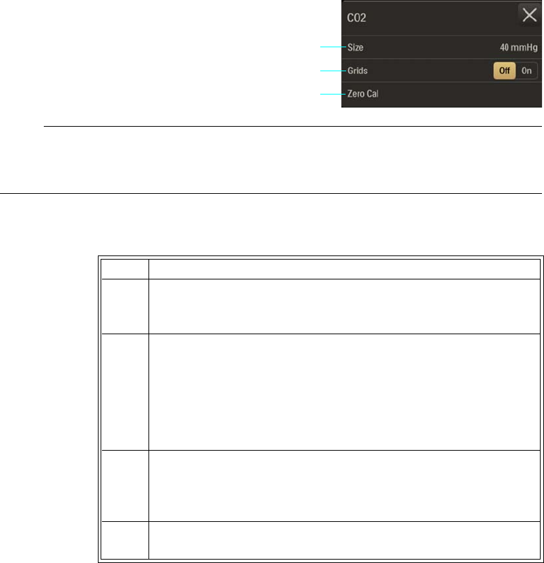
ExpressionMR400InstructionsforUse MonitoringCO2(LoFloOption)7‐13
ThefollowingCO2menuitemsareavailable:
Note
Apnea and Apnea Time will be in the CO2 menu when bellows (BEL) is the selected RESP >
Source; see page 10-7 for setting details.
TochangesettingsintheCO2menu
Size
ControlsthesizeoftheCO2waveform.
Thefollowingoptionsareavailable:
•40mmHg(Default)
•60mmHg
•80mmHg
1Size
2Grids
3Zero Cal
Step Action
1 SelecttheCO2VSbox.
TheCO2menuappears.Currentsettingsaredisplayed.
2TouchthemenuitemtoselectoneofthefollowingCO2options:
Size
Grids
ZeroCal
Themenuitemappears.Thecurrentsettingishighlighted.
3 Selectthedesiredsettingfromthemenuoptions(exceptGrids,
whichisselectableontheCO2menu).
Thesettingisentered.
4Tochangeothersettings,repeatsteps2and3.
2
3
1
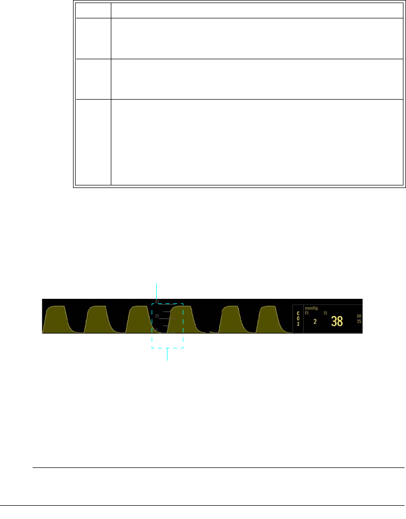
7‐14MonitoringCO2(LoFloOption) ExpressionMR400InstructionsforUse
ToadjustthesizeoftheCO2waveform
Grids
Displaysascaledgrid,whichisgraduatedaccordingtotheSizeselectionfortheCO2waveform.
Thefollowingoptionsareavailable:
•Offdoesnotdisplayagrid.(Default)
•Ondisplaysagrid.
Note
Grids will not be displayed during a CO2 Accuracy Check; see page 3-30.
Step Action
1 SelecttheCO2VSbox.
TheCO2menuappears.Currentsettingsaredisplayed.
2 SelectSize.
TheSizemenuappears.Thecurrentsettingishighlighted.
3 Selectthedesiredsize:
40mmHg
60mmHg
80mmHg
Thesettingischanged.
Grid
Size

ExpressionMR400InstructionsforUse MonitoringCO2(LoFloOption)7‐15
TocontrolthedisplayfunctionfortheCO2grid
Zero Cal
Initiatesazerocalibration(anautomaticfunctionduringnormaluse)oftheCO2systemtoallow
forthedifferentcharacteristicsofeachaccessorytype.ZeroCalisnotrequiredwhenswitching
samplinglines.
Undercertainconditions,ZeroCalwillnotbeallowed:
•Iflessthan20secondshavepassedsincedetectionofthelastbreath;
•IftheCO2temperatureisunstable;or
•IfthesamplinglineisdisconnectedfromtheCO2port.
Toperformazerocalibration
Seepage7‐2.
Step Action
1 SelecttheCO2VSbox.
TheCO2menuappears.Currentsettingsaredisplayed.
2LocateGridsandselectthedesiredsetting:
Off
On
Thesettingisentered.
7‐16MonitoringCO2(LoFloOption) ExpressionMR400InstructionsforUse

ExpressionMR400InstructionsforUseMonitoringInvasiveBloodPressure8‐1
CHAPTER 8
Monitoring Invasive Blood Pressure
Whenequippedwiththeinvasivebloodpressureoption,theMR400providescompatibilitywith
standardinvasivebloodpressuretransducershavinga5µV/V/mmHgsensitivity,andofferstwo
invasivebloodpressurechannels,P1andP2.
Indications and Contraindications
Adult and Pediatric Patients
Indications
•Directarterialpressuremonitoring
•Leftatrialmonitoringwithanair‐eliminatingfilterbetweensolutionsourceandcontinuous
flushdevice
• Pulmonaryarterymonitoring(PAdistal)
•Venouspressuremonitoring(RAproximal)
•Cardiaccatheterization
Contraindications
•Leftatrialmonitoringwithoutanair‐eliminatingfilterbetweensolutionsourceand
continuousflushdevice
•Intracranialpressuremonitoring
• Compartmentalpressuremonitoring
•Intrauterinepressuremonitoring
Neonatal Patients
WARNING
Do not use a pressure administration cuff.
Indications
• Umbilicalarterycatheterizationofneonates
•Invasivepressuremonitoringwithinfusionpump
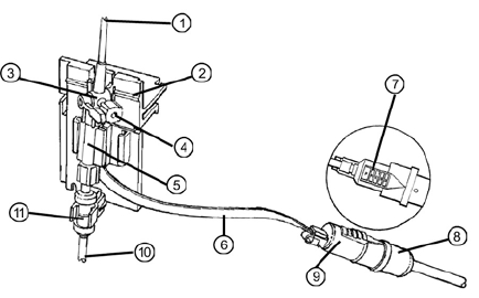
8‐2MonitoringInvasiveBloodPressure ExpressionMR400InstructionsforUse
Contraindications
•Leftatrialmonitoringwithoutanair‐eliminatingfilterbetweenthesolutionsourceand
continuousflushdevice
•Intracranialpressuremonitoring
• Compartmentalpressuremonitoring
• Intrauterinepressuremonitoring
Patient Preparation for IBP Monitoring
Whenpositioningthepatient,routineIBPmeasurements(includingforthecondition
hypertension)requirethepatienttoremainsilent,stillandrelaxed,withlegsuncrossedandarms
supported.NotethatduringMRIprocedures,patientsaretypicallylayingdownwiththeirlegs
uncrossedandarmssupportedasneededfortheMRIscan.Wealsorecommendwaiting5
minutesbeforetakingreadings.
Transducer Component, Connection, and Feature Locations
Theillustrationbelowdetailsthepressuretransducer(REF989803179721)component,feature,
andconnectionlocations.Ifusingadifferentkit,refertothemanufacturersinstructionswhich
accompanythatkit.
1To patient
2Site line
3Zero reference stopcock
4Zero port
5Transducer
6Transducer cable

ExpressionMR400InstructionsforUseMonitoringInvasiveBloodPressure8‐3
MR 400 Preparation for IBP Monitoring
FollowtheprocedurebelowtopreparetheMR400forIBPmonitoringwhenusingtheExpression
MRIBPDPTKits(Adult/Pediatric,REF989803194631;and,Infant/Neonatal,REF989803194641).
Astherearepreparationdifferences,alwaysfollowtheappropriateprocedure.
TopreparetheMR400forIBPmonitoringusingtransducerkitsotherthanthosereferenced
below,orforcomponentsaddedtothemonitoringsystem,refertoapplicablemanufacturer’s
instructionsforsetupanduse.
WARNINGS
• Invasive blood pressure transducers are sensitive to vibrations that can occur during
MRI scanning, which can lead to pressure reading inaccuracies. Always mount the invasive
blood pressure transducer away from areas where vibration is likely to occur.
• The fluid within the pressure transducer system is a conductive connection to the
patient, and must not contact other conductive parts, including earth ground.
• Do not allow fluids to enter the electrical connections of the transducer cables. Erratic
readings may result.
• Always reference the manufacturer’s instructions and follow the safe use instructions
included with the IBP transducer kit when monitoring invasive blood pressure.
• Never attach the pressure transducer(s) directly to the patient as excessive heating can
occur resulting in burn injuries to the patient.
• If air bubbles appear in the tubing system, flush the system with the infusion solution
again. Air bubbles may lead to a wrong pressure reading.
• Transducers do not protect against burns when used with high-frequency (HF)
surgical equipment.
• A transducer cable or other cable that becomes inadvertently looped during an MRI
examination may act as conductive lines for RF induced currents, resulting in
excessive heating and possible burns. When transducer cables or other cables form a
conductive loop in contact with the patient's tissue, minor to severe burning can result.
Do not allow the transducer cable or other cable to touch the patient or to become
looped. Please refer to the additional information in Appendix E to prevent excessive
heating associated with MRI procedures.
7Press here to disconnect transducer from reusable cable
8Reusable cable connector
9Transducer cable connector
10 To fluid source
11 Squeeze continuous flush device
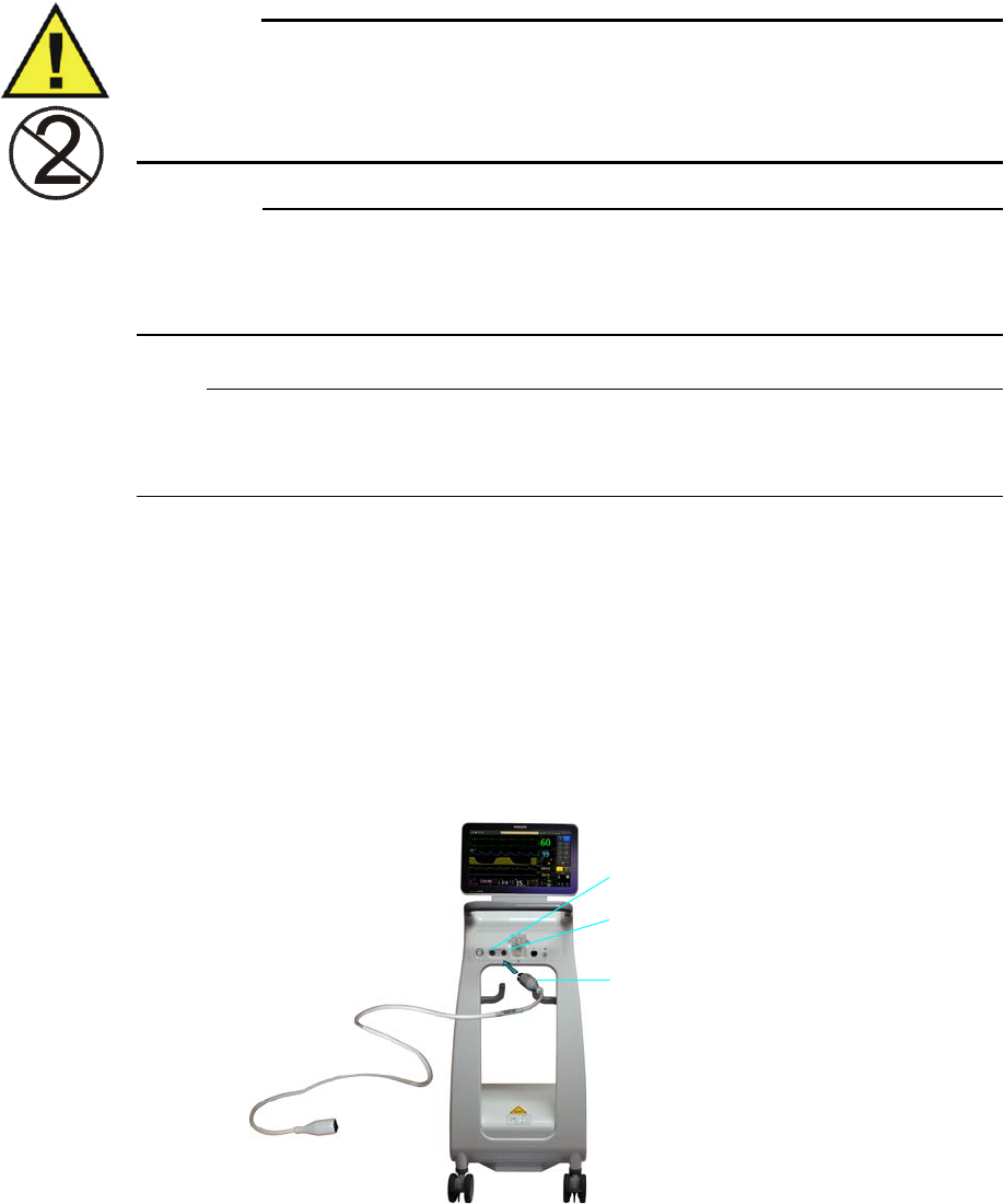
8‐4MonitoringInvasiveBloodPressure ExpressionMR400InstructionsforUse
WARNING
Disposable attachments are designed for single patient use and must be disposed after use.
They must not be cleaned and reused. Follow your hospital’s guidelines for appropriate
disposal. Reuse of single-use devices can result in spread of patient infection, degradation of
monitoring performance, or inaccurate measurements.
CAUTION
Use only approved pressure transducers and cables, as listed in Accessories in chapter 1, and
follow the Instructions for Use that are supplied with the pressure transducer to set up and use the
transducer monitoring kit.
Note
The procedure below details the connection of a single transducer. To monitor two IBP channels,
repeat the procedure to connect an additional transducer to the unused IBP port on the MR400.
Adult and Pediatric Patients: Expression MR IBP DPT Kit, A/P (REF 989803194631)
I. Connecting the Reusable Cable to the MR400
Connectthereusablecable,REF989803194601(orequivalent),totheP1ortheP2portonthe
patientconnectionpanel.
P2 port
Reusable cable
(REF 989803194601, or equivalent)
P1 port
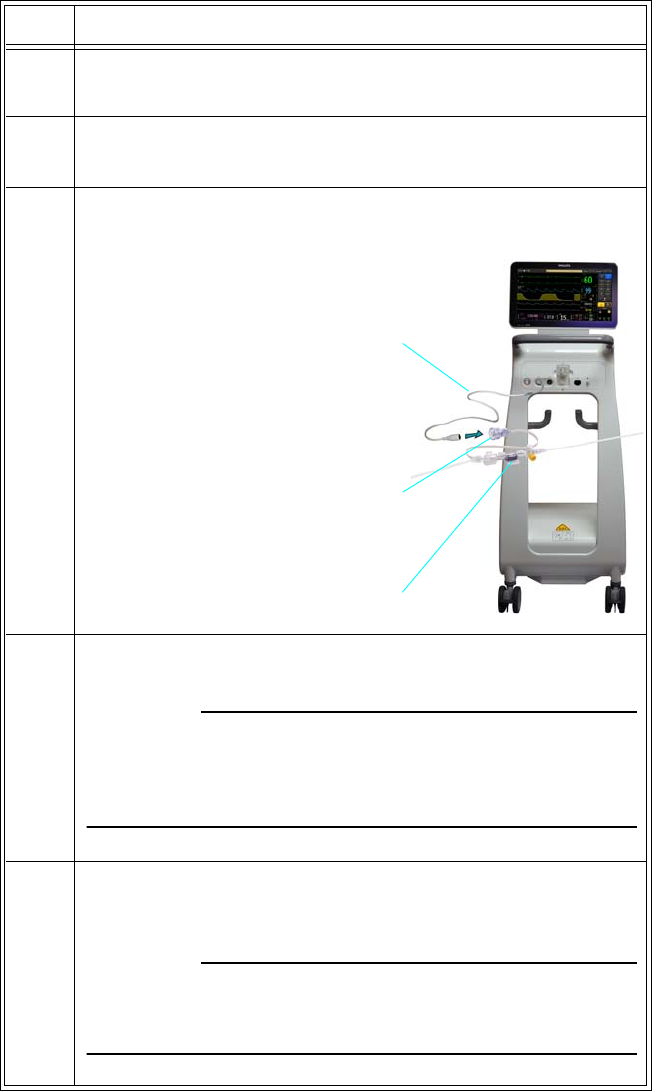
ExpressionMR400InstructionsforUseMonitoringInvasiveBloodPressure8‐5
II. Kit Set Up
Setupthedisposabletransducermonitoringkitusingaseptictechnique.
Step Action
1Openpackagecontainingthesteriledisposabletransducer
monitoringkit.
2 Removetransducermonitoringkitassemblyfromthepackage.
Checkallfittingstoensuretightconnection.
3Connectthereusablecable,REF989803194601(orequivalent),to
thetransducercable.
4 PrepareacollapsibleI.V.solutionbagbyextractingallairfromthe
bag.Ifheparinizing,addheparinpriortoairremoval.
CAUTION
If an air-free solution source is not used (i.e., air is not extracted
from the fluid source), air may be forced into the monitoring line
when solution is exhausted.
5Closetheclampontheadministrationsetandremovethe
protectivecapfromtheadministrationsetspike.Insertthespike
carefullyintotheI.V.solutionbag.
CAUTION
To prevent inadvertent puncture of the I.V. solution bag, insert the
spike carefully using a twisting motion.
Transducer
Reusable cable
(REF 989803194601, or equivalent)
Transducer cable

8‐6MonitoringInvasiveBloodPressure ExpressionMR400InstructionsforUse
III. Purging Air from the Monitoring Line
A. AttachthetransducertoanMRIVpolemount.
B.Turnzeroreferencestopcock“off”topatient.Removewhiteventedcapfromthesideport
ofthezeroreferencestopcock.
C.Activatefastflushmechanismofthecontinuousflushdeviceandfilltransducerslowly
(gravityprimeonly)untilair‐free.Flushfluidthroughtransducerandsideportofstopcock.
D.Turnhandleofzeroreferencestopcock“off”toitssideport.Placeayellownon‐ventedcap
ontothesideportofthestopcock.
E.RepeatprimingstepsB–Dforanyadditionalstopcocks.
F.Removewhitecoveratpatientconnectorandflushtherestofthepatientline.Placea
yellownon‐ventedcoverontothepatientconnector.
Note
Take care to ensure no air is trapped in any components of the fluid pathway. The monitoring
system must be totally air-free for maximum performance, i.e., optimal dynamic response.
G.PressurizetheI.V.solutionsourceto300mmHg.Closeclamponpressurecuff.
CAUTIONS
• Make certain the drip chamber does not completely fill during pressurization. Air should
remain in the drip chamber so that the continuous flush rate can be verified following a fast
flush.
• Pulling a vacuum to purge bubbles from the lines is not recommended. This practice may
entrain air or release air from solution. If the line is primed in a forward manner under
pressure, care must be taken to assure the maximum pressure specifications for the
transducer are not exceeded.
6InserttheI.V.solutionbagintothepressureadministrationcuff.
7HangthepressureadministrationcufffromanMRI.V.pole.
8Withtheadministrationsetclampclosed,gentlysqueezethedrip
chamberandfilldripchamberapproximately1/2full.
9Openclamponadministrationset.
Step Action

ExpressionMR400InstructionsforUseMonitoringInvasiveBloodPressure8‐7
IV. Zeroing, Leveling and Calibration
A. Afterthesystemhasbeenprimedandmounted,zerothetransducerusingoneofthe
followingmethods:
—Or—
Step Action
1Turnthezeroreferencestopcock“off”tothepatientandremove
yellownon‐ventedcapfromthesideportwhichopensthezero
referencestopcocktoair.
Note
The air-fluid interface of the zero reference stopcock should be at or
near the right atrial (mid-axillary) level.
2Zerothetransducer.PresstheZeroAllkey.(Otherwise,tozeroa
singlechannel,useZeroSetintherespectiveP1orP2menu;see
page8‐24).
ZeroingAllPressureChannels(orZeroingPressureChannelfora
singlechannelifZeroSetwasused)willbedisplayedandzeroing
willbegin;where,uponcompletion,Donewillbedisplayedto
indicatesuccess.
Note
If the transducer will not zero and an error condition occurs, verify
that the transducer is being used as described in the manufacturer’s
instructions. Press Retry to attempt zeroing again. If the transducer
still does not zero, try another transducer and/or cable; and, if
condition persists, contact technical support or authorized service
personnel.
3Turnthezeroreferencestopcock“off”tothesideportandreplace
yellownon‐ventedcap.
Step Action
1 Attachdesiredcathetertodistalendofmonitoringkitandprime,
purgingallairbubblesfromcatheter.
2Openstopcock(s)tothecatheter.(Thecathetertipisnowthe
systemair‐fluidinterface.)

8‐8MonitoringInvasiveBloodPressure ExpressionMR400InstructionsforUse
B. Repeatthiszeroing,leveling,andcalibrationprocedureforeachadditionalmonitoringline
asapplicable.
C. Transducersarepre‐calibratedtoindustrystandards.
V. Connecting the Monitoring Kit to the Patient
WARNING
The IBP transducer must not be mounted to the patient, or patient burn may result.
A. Removeyellownon‐ventedcoveratpatientconnector.Acontinuousflushofapproximately
3mlperhourshouldbeobservedinthedripchamber.Droprateshouldbeapproximately1
dropperminute.Foreachadditionalmonitoringline,thecontinuousflushwillincreaseby3
ml/hr(i.e.,6ml/hrfortwolines).
B. Forasystemicarterialbloodpressureline,activatethefastflushmechanismofthe
continuousflushdevice,whileallowingarterialcannulatobackflowduringattachment.For
pulmonaryarterycatheters,themonitoringkitshouldbeattachedtothecatheterandthe
3Placetransducerintheposition(horizontalplane)itwillmaintain
duringpressuremeasurement.
4Placethecathetertipattherightatrial(mid‐axillary)level.
5Zerothetransducer.Zerothetransducer.PresstheZeroAllkey.
(Alternatively,useZeroSetintherespectiveP1orP2menutozero
aspecificchannelconnectedtothetransducer;seepage8‐24).
ZeroingAllPressureChannels(orZeroingPressureChannelfora
singlechannelifZeroSetwasused)willbedisplayedandzeroing
willbegin;where,uponcompletion,Donewillbedisplayedto
indicatesuccess.
Note
If the transducer will not zero and an error condition occurs, verify
that the transducer is being used as described in the manufacturer’s
instructions. Press Retry to attempt zeroing again. If the transducer
still does not zero, try another transducer and/or cable; and, if
condition persists, contact technical support or authorized service
personnel.
Step Action
ExpressionMR400InstructionsforUseMonitoringInvasiveBloodPressure8‐9
catheterfilledwithI.V.solutionpriortoinsertion.Followcathetermanufacturer’sinsertion
instructions.
VI. Fast Flushing
A. Activatethefastflushmechanismofthecontinuousflushdeviceandcheckdripchamberto
confirmfastflush.
B. FOLLOWINGEACHFASTFLUSH,DRIPCHAMBERDROPRATEMUSTBEOBSERVEDTO
VERIFYCOMPLETECLOSURE.
VII. Checking for Leaks
Afterapproximately1minutehaselapsed,theflowrateshouldbeobservedatthedripchamber
toensurethatthecontinuousflushdeviceisoperatingproperly.Avisualinspectionforleaks
shouldalsobemadesinceasmallleakcanmisrepresenttheactualcontinuousflowthroughthe
catheter.Aprotocolshouldbeestablishedaccordingtothehospitalstandardofcareforroutinely
checkingthesystemforproperfluidsourcepressure,flowrateandleaks.
VIII. In the MR Room
WARNINGS
•The IBP transducer must not be allowed past the 5,000 gauss line, or transducer
failure, inaccurate readings, noisy MRI images or patient burn may result.
• Never place the pressure transducer’s stopcocks or port covers within 8 cm (3.2
inches) of the field of view of the MR bore as inaccurate readings or noisy MRI images
can result.
• An offset occurs when the pressure transducer is repositioned in the magnetic field.
The transducer must be zeroed prior to the MRI examination after the transducer is in
its final setup position. Moving the transducer after zeroing may cause a measurement
offset to occur.
IntheMRroom,ensurethatthetransducerislevelwiththeheartthatthetransducerinterface
cablingisnotloopedortouchingthepatient(refertheWarningsonpages8‐3and8‐4),andthen
re‐zerothetransducer;seepage8‐16.
WARNING
Non-physiological pulsatile P1 (or P2) waveform (for example, those found during intra-
aortic balloon pump use) can lead to inaccurate blood pressure readings. If questionable
values are observed, recheck the patient’s pressures by alternate means before administering
medication or therapy.
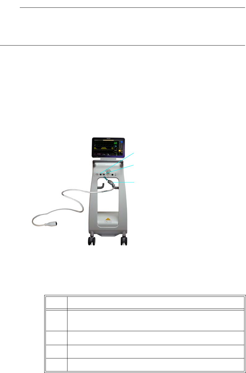
8‐10MonitoringInvasiveBloodPressure ExpressionMR400InstructionsforUse
Note
When monitoring invasive blood pressure, routinely inspect the catheter and/or pressure line for
leaks after zeroing, and always follow the pressure transducer/catheter manufacturer’s use
recommendations.
Neonatal Patients: Expression MR IBP DPT Kit, I/N (REF 989803194641)
I. Connecting the Reusable Cable to the MR400
Connectthereusablecable,REF989803194601(orequivalent),totheP1ortheP2portonthe
patientconnectionpanel.
II. Kit Set Up
A. Setupthedisposabletransducermonitoringkitusingaseptictechnique
Step Action
1Openpackagecontainingthesteriledisposabletransducermonitor‐
ingkit.
2 Removetransducermonitoringkitassemblyfrompackage.
3 Attachadditionalmonitoringcomponentsasdesired.
4Checkallfittingstoensuretightconnections.
P2 port
Reusable cable
(REF 989803194601, or equivalent)
P1 port
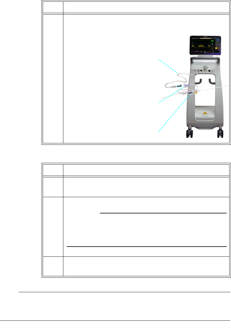
ExpressionMR400InstructionsforUseMonitoringInvasiveBloodPressure8‐11
B. PreparingSolution
Note
If an air-free solution source is not used (i.e., air is not extracted from the fluid source), air may
be forced into the monitoring line when solution is exhausted.
5Connectthereusablecable,REF989803194601(orequivalent),to
thetransducercable.
Step Action
1 Assemblepumpadministrationsetappropriatefortheinfusion
pumpthatistobeused.
2Ifusingheparin,addpriortoairremoval.
CAUTION
If an air-free solution source is not used (i.e., air is not extracted
from the fluid source), air may be forced into the monitoring line
when solution is exhausted.
3 Attachtubingtosolutioncontainerandprimethetubingfollowing
pumpmanufacturer’sinstructions.
Step Action
Transducer
Reusable cable
(REF 989803194601, or equivalent)
Transducer cable

8‐12MonitoringInvasiveBloodPressure ExpressionMR400InstructionsforUse
C. ConnectingKittotheInfusionPump
III. Purging Air from the Monitoring Line
A.Removetheventedcapfromthestopcocksandtheventedcoverfromthepatientconnector
(distalstopcock).
B.Adjustthepumpdeliveryregulatortoafluidflowratesufficienttoflushsolutionthroughthe
system.
C.CarefullyfillfluidlinesofthemonitoringkitwithI.V.solutionuntilallairhasbeenremoved
fromthesystem.Activateflushdevicetofacilitatefillingandtoremoveairfromflushdevice.
Turnstopcockhandlesasapplicabletoprimethroughsideportsofstopcocks.Non‐vented
capsandcoversareprovidedinthesparepartsbagtoreplaceventedcapsandcoversas
required.
CAUTION
Pulling a vacuum to purge bubbles from the lines is not recommended. This practice may entrain
air or release air from solution. If the line is primed in a forward manner under pressure, care must
be taken to assure the maximum pressure specifications for the transducer are not exceeded.
Note
Take care to ensure no air is trapped in any components of the fluid pathway. The monitoring
system must be totally air-free for maximum performance, i.e., optimal dynamic response.
IV. Zeroing, Leveling and Calibration
A. Afterthesystemhasbeenprimedandmounted,zerothetransducerusingoneofthe
followingmethods:
Step Action
1 Removeventedcapfromthefemaleportofflushdeviceandcon‐
nectflushdevicefluidlinetodistalconnectorofinfusionpump
administrationset.
CAUTION
In this application, the flush device is not intended to control flow
rate. Flow rate must be controlled by an infusion pump. Do not use
with pressure administration cuff.

ExpressionMR400InstructionsforUseMonitoringInvasiveBloodPressure8‐13
—Or—
Step Action
1Turnthezeroreferencestopcock“off”tothepatientandremove
non‐ventedcapfromthesideportwhichopensthezeroreference
stopcocktoair.
Note
The air-fluid interface of the zero reference stopcock should be at or
near the right atrial (mid-axillary) level.
2Zerothetransducer.PresstheZeroAllkey.(Otherwise,tozeroa
singlechannel,useZeroSetintherespectiveP1orP2menu;see
page8‐24).
ZeroingAllPressureChannels(orZeroingPressureChannelfora
singlechannelifZeroSetwasused)willbedisplayedandzeroing
willbegin;where,uponcompletion,Donewillbedisplayedto
indicatesuccess.
Note
If the transducer will not zero and an error condition occurs, verify
that the transducer is being used as described in the manufacturer’s
instructions. Press Retry to attempt zeroing again. If the transducer
still does not zero, try another transducer and/or cable; and, if
condition persists, contact technical support or authorized service
personnel.
3Turnthezeroreferencestopcock“off”tothesideportandreplace
non‐ventedcap.
Step Action
1 Attachdesiredcathetertodistalendofmonitoringkitandprime,
purgingallairbubblesfromcatheter.
2Openstopcock(s)tothecatheter.(Thecathetertipisnowthesys‐
temair‐fluidinterface.)
3Placetransducerintheposition(horizontalplane)itwillmaintain
duringpressuremeasurement.
4Placethecathetertipattherightatrial(mid‐axillary)level.
8‐14MonitoringInvasiveBloodPressure ExpressionMR400InstructionsforUse
B. Transducersarepre‐calibratedtoindustrystandards.
V. Connecting the Monitoring Kit to the Patient
WARNING
The IBP transducer must not be mounted to the patient, or patient burn may result.
A. Removenon‐ventedcoveratpatientconnector.
B. Settheinfusionpumptodeliverthedesiredflowrate.Continuouslowflowflushshouldbe
observedatthepatientconnectoranddripchamber(ifprovided)atthistime.
CAUTION
Kits with a 30 ml per hour flush device are not intended to control flow rate. Flow rate must be
controlled by an infusion pump. Do not use with pressure administration cuff.
C. Activatepumpdeliverymechanismtopumpsolutionthroughtheflushdevicewhileallowing
arterialcannulatobackflowduringattachment.
5Zerothetransducer.PresstheZeroAllkey.(Alternatively,useZero
SetintherespectiveP1orP2menutozeroaspecificchannel
connectedtothetransducer;seepage8‐24).
ZeroingAllPressureChannels(orZeroingPressureChannelfora
singlechannelifZeroSetwasused)willbedisplayedandzeroing
willbegin;where,uponcompletion,Donewillbedisplayedto
indicatesuccess.
Note
If the transducer will not zero and an error condition occurs, verify
that the transducer is being used as described in the manufacturer’s
instructions. Press Retry to attempt zeroing again. If the transducer
still does not zero, try another transducer and/or cable; and, if
condition persists, contact technical support or authorized service
personnel.
Step Action
ExpressionMR400InstructionsforUseMonitoringInvasiveBloodPressure8‐15
CAUTIONS
• Be certain not to introduce air into the system during connection procedure.
• If this product is used with fat emulsions, they must be introduced through the lipid
compatible stopcock that is distal to the flush transducer assembly to avoid cracking of the
transducer line.
VI. Checking for Leaks
Afterapproximately1minutehaselapsed,theflowrateshouldbeobservedatthedripchamber
toensurethatthecontinuousflushdeviceisoperatingproperly.Avisualinspectionforleaks
shouldalsobemadesinceasmallleakcanmisrepresenttheactualcontinuousflowthroughthe
catheter.Aprotocolshouldbeestablishedaccordingtothehospitalstandardofcareforroutinely
checkingthesystemforproperfluidsourcepressure,flowrateandleaks.
VII. In the MR Room
WARNINGS
•The IBP transducer must not be allowed past the 5,000 gauss line, or transducer
failure, inaccurate readings, noisy MRI images or patient burn may result.
• Never place the pressure transducer’s stopcocks or port covers within 8 cm (3.2
inches) of the field of view of the MR bore as inaccurate readings or noisy MRI images
can result.
• An offset occurs when the pressure transducer is repositioned in the magnetic field.
The transducer must be zeroed prior to the MRI examination after the transducer is in
its final setup position. Moving the transducer after zeroing may cause a measurement
offset to occur.
IntheMRroom,ensurethatthetransducerislevelwiththeheartthatthetransducerinterface
cablingisnotloopedortouchingthepatient(refertotheWarningsonpages8‐3and8‐4),and
thenre‐zerothetransducer;seepage8‐16.
WARNING
Non-physiological pulsatile P1 (or P2) waveform (for example, those found during intra-
aortic balloon pump use) can lead to inaccurate blood pressure readings. If questionable
values are observed, recheck the patient’s pressures by alternate means before administering
medication or therapy.

8‐16MonitoringInvasiveBloodPressure ExpressionMR400InstructionsforUse
Note
When monitoring invasive blood pressure, routinely inspect the catheter and/or pressure line for
leaks after zeroing, and always follow the pressure transducer/catheter manufacturer’s use
recommendations.
Zeroing the Pressure Transducer
WARNING
The transducer must be zeroed prior to the MRI examination after the transducer is in its
final setup position. Moving the transducer after zeroing may cause a measurement offset to
occur. Otherwise, inaccurate patient pressure readings may result.
Toavoidinaccuratepressurereadings,themonitorrequiresavalidzero.Zerothetransducerin
accordancewithyourhospitalpolicy(atleastonceperday).Youmustperformazero:
•whenyouuseanewtransducerortubing,
•everytimeyoureconnectthetransducercabletothemonitor,or
•ifyouthinkthemonitor’spressurereadingsarenotcorrect.
Tozeroapressuretransducer
Refertotheappropriateprocedureaccordingtothepatienttypeandapplication:
•Adult/Pediatric—seepage8‐7.
•Neonate—seepage8‐12.
P1 and P2 Waveforms and VS Boxes
Invasivebloodpressuremeasurements(P1andP2)aredisplayedaswaveforms(traceEandtrace
F,respectively)intheVStraceareaofthescreenandasnumericinformationintheP1andP2VS
boxes.Otherdata,includingP1‐andP2‐relatedalarminformation,arealsoprovidedinthese
areasofthescreen,asdetailedbelow.
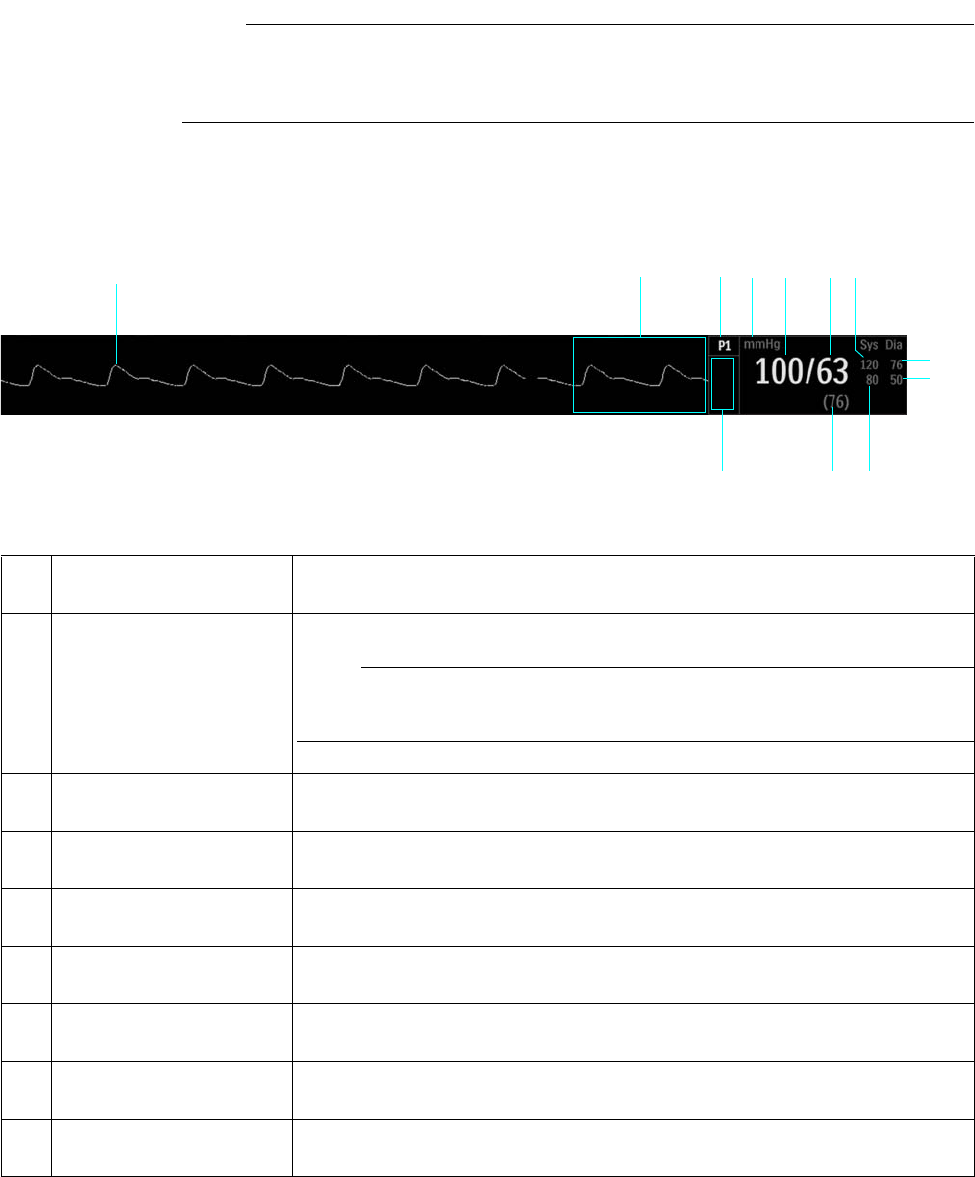
ExpressionMR400InstructionsforUseMonitoringInvasiveBloodPressure8‐17
Note
Except for the VS box annotations and waveform locations, the definitions described below are
applicable to both P1 and P2 channels.
Systolic/Diastolic Format
15
23
8
7
46
9
11 10
12
Item Name Definition
1 P1 VS waveform, or P2 VS
waveform
Is the detected P1 (or P2) waveform, Trace E (or Trace F)
Note
To change the waveform speed, see Sweep Speed on page 3-25.
2 Alarm flag area Displays P1 (or P2) alarm flags when detected; see page 4-31.
3 P1 (or P2) VS box label Indicates the P1 (or P2) vital sign parameter, and accesses the P1 menu (or P2
menu)
4 Unit of measure Indicates that the pressure measurement numeric values are given in mmHg
(millimeters of mercury) or kPa (kilopascals); see Pressure Units on page 3-32.
5 Systolic numeric Is the patient’s detected systolic invasive blood pressure measurement
6 Diastolic numeric Is the patient’s detected invasive diastolic blood pressure measurement
7 Systolic upper alarm limit Is the upper limit setting for the P1 (or P2) systolic alarm, and accesses the P1
Alarm Limits menu (or the P2 Alarm Limits menu)
8 Diastolic upper alarm limit Is the upper limit setting for the P1 (or P2) diastolic alarm, and accesses the P1
Alarm Limits menu (or the P2 Alarm Limits menu)
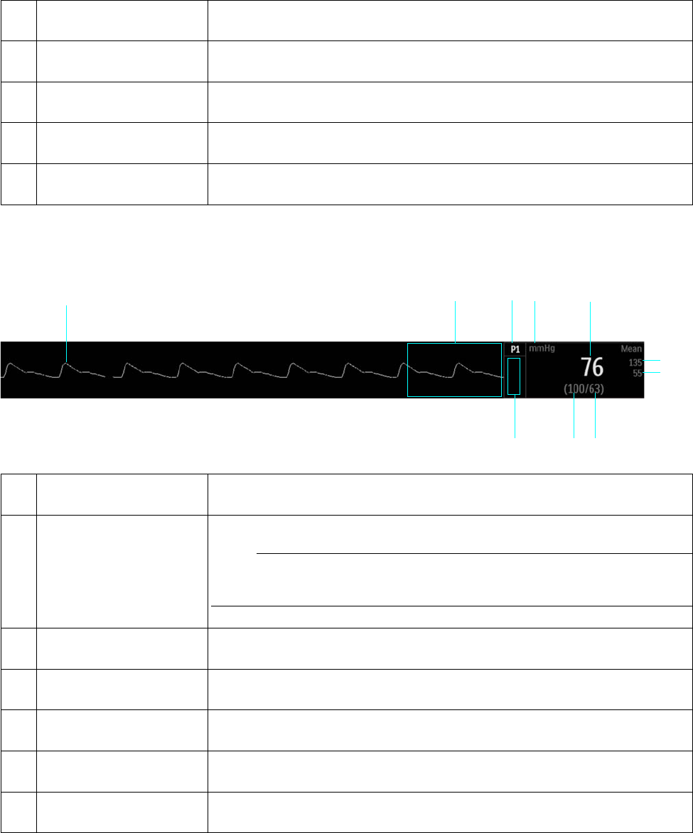
8‐18MonitoringInvasiveBloodPressure ExpressionMR400InstructionsforUse
Mean Format
9 Diastolic lower alarm limit Is the lower limit setting for the P1 (or P2) diastolic alarm, and accesses the P1
Alarm Limits menu (or the P2 Alarm Limits menu)
10 Systolic lower alarm limit Is the lower limit setting for the P1 (or P2) systolic alarm, and accesses the P1
Alarm Limits menu (or the P2 Alarm Limits menu)
11 Mean numeric Indicates the patient’s detected mean invasive blood pressure measurement
12 <P1 label> or <P2 label> Indicates the Set Label name, if assigned, for P1 (or P2)
Item Name Definition
123
6
45
7
8
10 9
Item Name Definition
1 P1 VS waveform, or P2 VS
waveform
Is the detected P1 (or P2) waveform, Trace E (or Trace F)
Note
To change the waveform speed, see Sweep Speed on page 3-25.
2 Alarm flag area Displays P1 (or P2) alarm flags when detected; see page 4-31.
3 P1 (or P2) VS box label Indicates the P1 (or P2) vital sign parameter, and accesses the P1 menu (or P2
menu)
4 Unit of measure Indicates that the pressure measurement numeric values are given in mmHg
(millimeters of mercury) or kPa (kilopascals); see Pressure Units on page 3-32.
5 Mean numeric Is the patient’s detected mean invasive blood pressure measurement
6 Mean upper alarm limit Is the upper limit setting for the P1 (or P2) mean alarm, and accesses the P1 Alarm
Limits menu (or the P2 Alarm Limits menu)

ExpressionMR400InstructionsforUseMonitoringInvasiveBloodPressure8‐19
Changing the P1 (or P2) Format
TocontroltheformatoftheP1(orP2)data
Changing the P1 (or P2) Waveform Amplitude
TheverticalscaleofthedisplayedP1(orP2)waveformcanbechangedtobestsuittheviewing
requirements.Alwaysselecttheappropriatewaveformscaleforthewaveformbeingobserved.
7 Mean lower alarm limit Is the lower limit setting for the P1 (or P2) mean alarm, and accesses the P1 Alarm
Limits menu (or the P2 Alarm Limits menu)
8 Diastolic numeric Is the patient’s detected invasive diastolic blood pressure measurement
9 Systolic numeric Indicates the patient’s detected systolic invasive blood pressure measurement
10 <P1 label> or <P2 label> Indicates the Set Label name, if assigned, for P1 (or P2)
Item Name Definition
Step Action
1 SelecttheP1(orP2)VSbox.
TheP1menu(ortheP2menu)appears.Currentsettingsare
displayed.
2 SelectFormat.
TheFormatmenuappears.Thecurrentsettingishighlighted.
3 Selectthedesiredformat:
SysDia
Mean
Theformatischanged.
Note
When using P1 (or P2) labels CVP or ICP, the displayed format
cannot be changed; see page 8-28 for details.
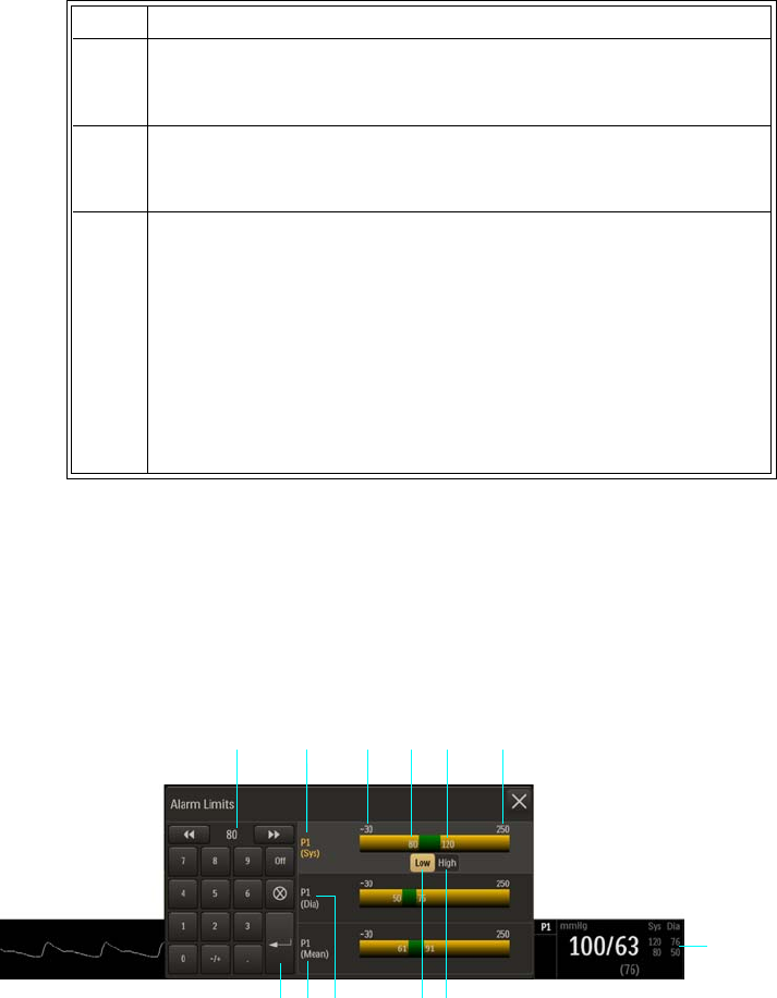
8‐20MonitoringInvasiveBloodPressure ExpressionMR400InstructionsforUse
TochangetheP1(orP2)waveformamplitude
Changing the P1 (or P2) Alarm Limits
TheP1AlarmLimitsmenucanbeaccessedbytouchingthealarmlimitsettingsintheP1vitalsign
box,andtheP2AlarmLimitsmenucanbeaccessedbytouchingthealarmlimitsettingsintheP2
vitalsignbox.Exceptformenulabelingdifferences,theelementsdescribedbelowareapplicable
toboththeP1andP2parameters.
Step Action
1 SelecttheP1(orP2)VSbox.
TheP1(orP2)menuappears.Currentsettingsaredisplayed.
2 SelectSize.
TheSizemenuappears.Thecurrentsettingishighlighted.
3 Selectthedesiredsize:
40mmHg
75mmHg
100mmHg
150mmHg(Default)
200mmHg
250mmHg
Thesettingischanged.
1Alarm limit settings, P1 VS box
2High button
3Low button
4 P1 Diastolic Alarm Limits menu label
5P1 Mean Alarm Limits menu label
6Enter button
7
1
2
35 46
8 9 10 11 12

ExpressionMR400InstructionsforUseMonitoringInvasiveBloodPressure8‐21
Tochangetheinvasivebloodpressurealarmlimitsettings
Note
See chapter 4 for detailed alarm limit setting instructions and options.
7Current adjustment
8P1 Systolic Alarm Limits menu label (active adjustment shown)
9Alarm limit, minimum
10 Lower P1 (Sys) alarm limit setting
11 Upper P1 (Sys) alarm limit setting
12 Alarm limit, maximum
Step Action
1 SelectthealarmlimitsettingsintheP1(orP2)VSbox.
TheP1AlarmLimits(ortheP2AlarmLimits)menuappears.
Currentsettingsaredisplayed.
2 Selectthedesiredpressuresetting:
P1(Sys)
P1(Dia)
P1(Mean)
Thesettingisselected.
3 SelecttheLowbuttonortheHighbutton.
Theselectedbuttonwillbehighlightedandthecurrentadjustment
willbedisplayed.
4Usingthekeypad,ortheincrement,decrement,orOffbuttons,
enterthedesiredsetting.
Thecurrentadjustmentwillreflectthechange.
5PresstheEnterbuttontosavethesetting.
Thealarmlimitsettingisupdated.
6
Tochangetheremainingsettings,repeatsteps2,3,4and5.
Thecurrentadjustmentwillreflectthechange.

8‐22MonitoringInvasiveBloodPressure ExpressionMR400InstructionsforUse
Changing the Unit of Measure
Note
When using an IP5 and Pressure Units is changed, the displayed formatting of the value and
placement of the decimal point is changed immediately. However, it can take up to 2 seconds for
the measurement numeric values to reflect the new unit of measure. Do not print or perform data
captures during this period.
Tochangetheunitofmeasure
P1 (and P2) Menu
TheP1andP2menusallowyoutocontrolinvasivebloodpressuretraces,functionsandsettings.
Eachmenucontainsidenticaloptionsforthecontroloftherespectiveinvasivebloodpressure
channel,P1orP2.
Note
The operation and menus for P1 and P2 are identical.
Step Action
1PresstheSetupkeyandthentheMonitorkey.
TheMonitorSetupmenuappears.Currentsettingsaredisplayed.
2OntheMonitorSetupmenu,selectService(Bio‐Med).
TheService(Bio‐Med)menuappears.Currentsettingsare
displayed.
3OntheService(Bio‐Med)menu,selectSystemConfig.
TheSystemConfigmenuappears.Currentsettingsaredisplayed.
4OntheSystemConfigmenu,selectPressureUnits.
ThePressureUnitsmenuappears.Thecurrentsettingis
highlighted.
5 Selectthedesiredsetting:
mmHg
kPa
Thesettingisentered.
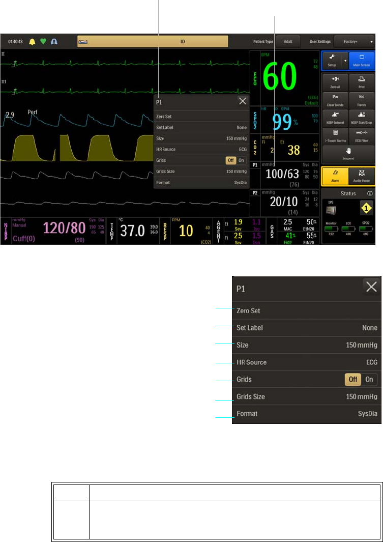
ExpressionMR400InstructionsforUseMonitoringInvasiveBloodPressure8‐23
ToopentheP1menu(orP2menu)
SelecttheP1VSbox(ortheP2VSbox).
ThefollowingP1(andP2)menuitemsare
available:.
TochangesettingsintheP1(orP2)menu
1Zero Set
2Set Label
3Size
4HR Source
5Grids
6Grids Size
7Format
Step Action
1 SelecttheP1(orP2)VSbox.
TheP1(orP2)menuappears.Currentsettingsaredisplayed.
P1 menu
P1 VS box
2
3
4
1
5
6
7

8‐24MonitoringInvasiveBloodPressure ExpressionMR400InstructionsforUse
Zero Set
ZerosthepressuretransducerforP1(orP2).Thepressuretransducermustbezeroedbeforeuse
andatregularintervalsduringuse.(ZeroPressureChannelwillbedisplayedduringtheprocess
andDonewillbedisplayeduponcompletion.)
Tozerothepressuretransducer
SeeZeroingthePressureTransduceronpage8‐16.
Set Label
Assignsalabeltothepressurechannelforidentificationofthetransducersite.Thelabelwill
appearintheVSboxanditwillalsodeterminethecolorusedfortheVSbox.
Thefollowingnamesandcolorsareavailable:
•Nonedisplayedinwhite.(Default)
•ABP(arterialbloodpressure)displayedinpink.
Note
In the event ABP is chosen as the heart rate source while there are multiple pressures labeled as
ABP, the system will choose P1.
•PAP(pulmonaryarterypressure)displayedinyellow.
2TouchthemenuitemtoselectoneofthefollowingP1(orP2)
options:
ZeroSet
SetLabel
Size
HRSource
Grids
GridsSize
Format
Themenuitemappears.Thecurrentsettingishighlighted.
3 Selectthedesiredsettingfromthemenuoptions(exceptGrids,
whichisselectableontheP1[orP2]menu):
Thesettingisentered.
4Tochangeothersettings,repeatsteps2and3.
Step Action

ExpressionMR400InstructionsforUseMonitoringInvasiveBloodPressure8‐25
•CVP(centralvenouspressure)displayedinblue.
•LAP(leftatrialpressure)displayedinpurple.
•ICP(intracranialpressure)displayedinlightblue.
ToassignalabeltoanP1(orP2)channel
Size
ChangestheP1(orP2)waveformamplitude,allowinglowlevelsignalstobescaleduporhigh
levelsignalstobescaleddownforbetterviewing.
Thefollowingoptionsareavailable:
•40mmHg
•75mmHg
•100mmHg
•150mmHg(Default)
•200mmHg
•250mmHg
TochangetheamplitudeoftheP1(orP2)waveform
SeeChangingtheP1(orP2)WaveformAmplitudeonpage8‐19.
Step Action
1 SelecttheP1(orP2)VSbox.
TheP1menu(ortheP2menu)appears.Currentsettingsare
displayed.
2 SelectSetLabel.
TheSetLabelmenuappears.Thecurrentsettingishighlighted.
3 Selectthedesiredlabel:
None
ABP
PAP
CVP
LAP
ICP
Thelabelischanged.TheannotationintheVSboxanditscoloris
updated.

8‐26MonitoringInvasiveBloodPressure ExpressionMR400InstructionsforUse
HR Source
Selectsthesourcethatproducestheheartrate,asdisplayedintheECGandSPO2VSboxes
(identicaltoandinteractivewithsameoptionintheECGandSPO2menus).
Thefollowingoptionsareavailable:
•Autosetsthesourceautomaticallyaccordingtothehighestpriorityactiveinputthatisfirst
toreportvalidpatientdata.Thepriorityranking(highesttolowest)isECG,P1,P2,SPO2
(providedthattheP1andP2channelshavebeenlabeledABP;seeSetLabelonpage8‐24
fordetails).Thesourcewillbecomeunavailablewhenithasproducednovaliddatafora
periodoften(10)ormoreseconds.Thesystemexaminesthehighestpriorityactiveinput.
Ifnotfound,thesecond‐highestpriorityinputischosen,etcetera.Ifnonearepresent,
thenNoneisdisplayedastheheartratemeasurementnumeric.
•ECGsetsECGasthesource.(Default)
•ABPsetsABPasthesource(ifnopressurechannelislabeledABP,awarningboxwillallow
automaticrenamingandselectionbeforeproceeding;alsoseeSetLabelonpage8‐24).
•SPO2setsSPO2asthesource.
Tosettheheartratesource
Grids
ControlsthepressuregriddisplayforIBPwaveforms.
Step Action
1 SelecttheP1(orP2)VSbox.
TheP1menu(ortheP2menu)appears.Currentsettingsare
displayed.
2 SelectHRSource.
TheHRSourcemenuappears.Thecurrentsettingishighlighted.
3 Selectthedesiredsettingfortheheartratesource:
Auto
ECG
ABP
SPO2
Thesourceischanged.
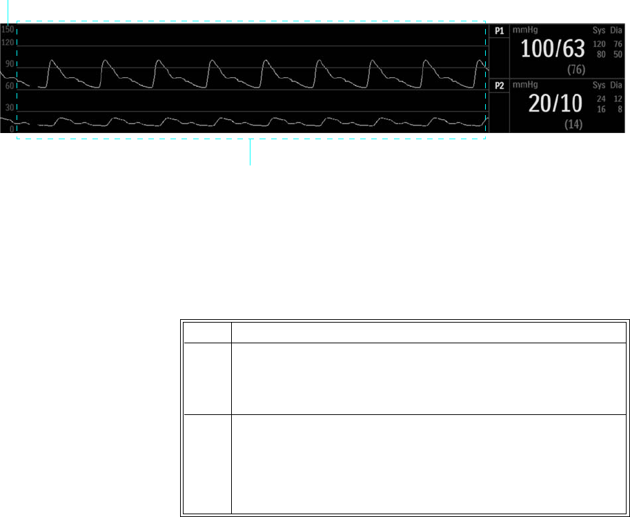
ExpressionMR400InstructionsforUseMonitoringInvasiveBloodPressure8‐27
Thefollowingoptionsareavailable:
•Offnogridisdisplayed.(Default)
•Ondisplaysascaledgrid(alsoseeGridsSize,below).
Tocontrolthedisplayfunctionforthepressuregrid
Grids Size
SetsthescalesizewhenGridsison(seeGrids,above).
Thefollowingoptionsareavailable:
•40mmHg
•75mmHg
•100mmHg
•150mmHg(Default)
•200mmHg
•250mmHg
Grid
Grids Size
Step Action
1 SelecttheP1(orP2)VSbox.
TheP1menu(ortheP2menu)appears.Currentsettingsare
displayed.
2LocateGridsandselectthedesiredsetting:
Off
On
Thesettingisentered.

8‐28MonitoringInvasiveBloodPressure ExpressionMR400InstructionsforUse
ToadjustthegridsizefortheP1(orP2)waveform
Format
SetsthedisplayedformatoftheP1(orP2)numericdata,exceptwhenusingcertainpressure
channellabels.
Thefollowingoptionsareavailable:
•SysDiadisplaysthesystolicanddiastolicnumericsinalargefont(separatedbyaslash)and
displaysthemeannumericinasmallerfont(bracketedwithparenthesis).(Default)
•Meandisplaysthemeannumericinalargefont,andthesystolicanddiastolicnumericsin
asmallerfontandseparatedbyaslash.Onlymeanalarmswillbepresentinthisformat.
Also,labels(i.e.,CVPandICP)thatdesignatesinglepressureswillautomaticallyassumethe
meanformat;seeSetLabelonpage8‐24.
TocontroltheformatoftheP1(orP2)numericdata
SeeChangingtheP1(orP2)Formatonpage8‐19.
Step Action
1 SelecttheP1(orP2)VSbox.
TheP1menu(ortheP2menu)appears.Currentsettingsare
displayed.
2 SelectGridsSize.
TheGridsSizemenuappears.Thecurrentsettingishighlighted.
3 Selectthedesiredsize:
40mmHg
75mmHg
100mmHg
150mmHg
200mmHg
250mmHg
Thesettingischanged.
ExpressionMR400InstructionsforUseMonitoringAgentsandGases(AGENTOption)9‐1
CHAPTER 9
Monitoring Agents and Gases (AGENT Option)
WhenequippedwiththeAGENToption,thepatient’slevelofanestheticagentgases,oxygen
(O2),carbondioxide(CO2),andnitrousoxide(N2O)concentrationscanbemonitored.An
anestheticgassensor(AGS)systemusesinfraredspectroscopycombinedwithdigitalsignal
processingtoquicklyandaccuratelyidentifygasconcentrations.
WARNING
Whenever a patient is under anesthesia or connected to a ventilator, constant attention by
qualified medical personnel is required.
MR400 Preparation for AGENT Monitoring
WhenpreparingtheMR400forAGENTmonitoring,ensurethatthewastegasport(seepage1‐
19)hasbeenconnectedtoyourfacility’sgasscavengingsystemfordisposalofsampledand
calibrationgases.
Notes
• These instructions are for setting up a typical monitoring system. Exact components and set-
up procedure used may vary, depending upon the application. For components added to the
monitoring system, refer to applicable manufacturer’s instructions for set up and use.
• Never route the waste gas tubing in a location that will allow it to be an obstruction or
stepped on.
Operation and Use
Whenmonitoringanestheticagentgases,thetypicaloperationsandpossibleconditionsthatcan
arisemayresultinpotentialmessagesrequiringyourattention.Seepage4‐26foramessage
listingandsuggestedactions.
9‐2MonitoringAgentsandGases(AGENTOption) ExpressionMR400InstructionsforUse
WARNINGS
•Organic vapors (for example, from cleaning agents) in the sampling line or room air
may alter anesthetic agent readings.
• Alcohol in the patient’s breath can modify the anesthetic agent readings.
Warm-Up Period
Inordertoachieveaccurateidentificationsandmeasurements,theAGSsystemrequiresawarm‐
upperiodtothermallystabilize.Thiswarm‐upperiodbeginswhentheAGENTortheCO2
parameterisactivated.Uponactivation,theAGSsystemwillbecomefullyoperationalaccording
tothefollowingsequence:
1. Duringthewarm‐upperiod,CO2WarmingUpwillbedisplayed.
2. Within45secondsofactivation,theAGSsystemwillbeabletoidentifythegasesand
providegasconcentrationinformationwithISO‐levelaccuracy.Waitduringthisperiod,the
measurementnumericvaluesintheAGENT,GAS,andCO2VSboxeswilldisplaythree
dashes(‐‐‐);seeNoDataIndicationonpage2‐20fordetails.
3. Within10minutesofactivation,theAGSsystemwillbeabletooperateatfullaccuracy.
Zero Reference Adjustment
WARNING
During Zero calibration the system pulls ambient air through the zero intake port on the cart
The calibration system assumes that the ambient air will contain normal trace amounts of
CO2. If the system is placed in an unventilated area that allows CO2 (from the waste gas port
on the rear panel, if not connected to a gas scavenging system) to accumulate, the result could
be inaccurate CO2 zeroing and resulting inaccurate patient readings. Always place the cart in
a well ventilated area.
TheAGSsystemwilloccasionallyperformazeroreferenceadjustment,brieflyinterruptinggas
monitoringtotakeinroomairthroughareferencegasintakeporttoensuretheaccuracyofthe
displayedgasconcentrations.
ReadjustingCO2Zerowillbedisplayedduringazeroreferenceadjustment;allowtheprocessto
complete.Azeroreferenceadjustmenttypicallytakes10–12seconds,andwilloccur
automaticallyasneeded,butmostlyduringthewarm‐upperiod.WhentheAGSsystemhas
becomefullyoperational,theseadjustmentswilloccurapproximatelyonceevery4hoursor
whenevertheAGSsystemtemperaturechangesbyatleast±1°Cfromthelaststoredstable
temperature.

ExpressionMR400InstructionsforUseMonitoringAgentsandGases(AGENTOption)9‐3
Note
Whenever the Agent sensor changes from a steady state condition, the system will perform an zero
reference adjustment to restabilize the sensor readings. During this time it is possible for a false
identification and concentration value to occur. Change from a steady state condition may occur
when:
– Applying a sampling line for the first time.
– Switching from one agent to another.
– Going from high agent concentrations to low or off.
Note
During the first hour after the system has been turned on and flowing oxygen greater than 50
percent, the CO2 waveform periodically baselines to complete reference measurement; however,
the measurement numeric values remain. Once the system reaches ambient temperature this
condition will cease to occur.
Toperformamanualzeroreferenceadjustment
Breath Rate Distortion
Theeffectofrisetimedistortiontothegascurvebecomesapparentwhenthebreathingrate
increasessothatthetimeforafullinspiratoryorexpiratoryeventgetsshorter.Inthose
situations,duetotheeffectoftherisetime,thegascurvedoesnotreachthetrueend‐tidal(or
firstinspiredvalue)andtheend‐tidalgasvaluemaythenbeunderestimated.Correspondingly,
thefirstinspiredvaluemaybeoverestimated.Belowisanexaggeratedillustrationoftheeffect.
Step Action
1 SelecttheCO2VSbox.
TheCO2menuappears.Currentsettingsaredisplayed.
2 SelectZeroCal.
Allowtheprocesstocomplete,typically10–12seconds.

9‐4MonitoringAgentsandGases(AGENTOption) ExpressionMR400InstructionsforUse
Thebreathratelimitforaccuratelyresolvedend‐tidalgasvalues(atanI:Eratioof1:1)maybe
foundinAppendixA.TheeffectofotherI:Eratiosmaybecalculatedbydeterminingthelengthof
theshortestinspiratory/expiratoryeventthatcanberesolvedaccurately:
tresolved=60/(2xBRlimit(1:1)
BRlimit(I:E)=60/((I+E)xtresolved)
Thedifferenceintheseresultswhencomparedtotherisetime'sspecificationisthatrisetime's
onlytests10‐90%performance.Thisspecificationisfor(0+accuracy)to(100‐accuracy)%andis
thusmuchtougher.Theabilitytoproperlyresolveend‐tidalvaluescanbemeasuredbyusingthe
set‐updescribedinISO80601‐2‐55:2011figure201.101.Inshort,themethodconsistsof
samplinggasfromtwodifferentsourcesconnectedtoanelectricallycontrolledpneumaticvalve
topermitrapidswitchingbetweenthetwosources.Duringthetest,thevalveissettoswitchgas
sourceatanumberoffrequencies(simulatingtherangeofspecifiedbreathrates)andforeach
frequencytheend‐tidalvaluepresentedbythegasanalyzerisnoted.Fromadiagramofend‐tidal
valueoverfrequency,thefrequencyatwhichthegasanalyzerisnolongerabletoresolveend‐
tidalvaluesaccordingtospecificationisidentified.Thisabilitytoproperlyresolveend‐tidalvalues
islistedinthespecification.
CO2 Low Flow and Occlusion Conditions
CO2LowFlowwillbedisplayedandanalarmwillsoundintheeventofalowflowcondition
(wheneverthegasflowfallstoanamountthatis10percentlessthanthesampleflowratefor
theselectedpatienttype),asshowninthetablebelow.
Occlusionwillbedisplayedandanalarmwillsoundintheeventofanocclusioncondition
(wheneverthegasflowratehasfallenbelow40ml/minforatleast1second.Thetypicalcauseof
Fi error
Percent
Time
Et error
- - at gas sampling site
— as presented by gas analyzer
Patient Type Sample Flow Rate Flow Rate when Low Flow is Declared
Adult 200 ml/min ≤ 180 ml/min
Pediatric 200 ml/min ≤ 180 ml/min
Neonate 150 ml/min ≤ 135 ml/min
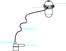
ExpressionMR400InstructionsforUseMonitoringAgentsandGases(AGENTOption)9‐5
thelowflowortheocclusionconditionisduetoapinchedsamplingline,orablockedsampling
lineduetoexcessivemoisturefrompatientexpiration.
Selecting AGENT Accessories
VariousaccessoriesareavailableforusewiththeAGENToption.Forexample,whenmonitoring
patientsonabreathingcircuit,asampleoftherespiratorygasisdrawnfromthepatient’s
breathingcircuitthroughanairwayadapterandsamplingline,orwhenpatientsarenotona
breathingcircuit,thesampleisdrawnthroughanasalcannula.WhenselectingAGENT
accessories(seepage1‐34foralisting),considerthefollowing:
•Thetypeofpatient(adult,pediatric,orneonatal)
•Theconditionofthepatient
•Whetherthepatientisonabreathingcircuit
•Whetherthepatientisreceivingsupplementaloxygen
•Allaccessoriesaresingleuse.
AGENT Tubing Preparation
VariouspneumaticcircuitconfigurationsforusewiththeAGENToptionareillustratedbelow:
•Monitoringusingtheairwayadapter
1Water trap
2Sample port (with Luer lock connector)
3Sampling line
4Luer lock connector
5Airway adapter connected to the patient airway
1
2
3
5
4
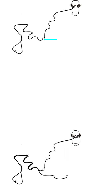
9‐6MonitoringAgentsandGases(AGENTOption) ExpressionMR400InstructionsforUse
•Monitoringusingthenasalcannula
•Monitoringusingadividednasalcannula(whendeliveringO2tothepatient)
1Water trap
2Sample port (with Luer lock connector)
3Sampling line
4Luer lock connector
5Nasal cannula connected to a patient airway
1Water trap
2Sample port (with Luer lock connector)
3Sampling line
4Luer lock connector
5Large tubing connector to patient O2 source
6Divided nasal cannula connected to a patient airway
1
2
3
4
5
1
2
3
5
6
4
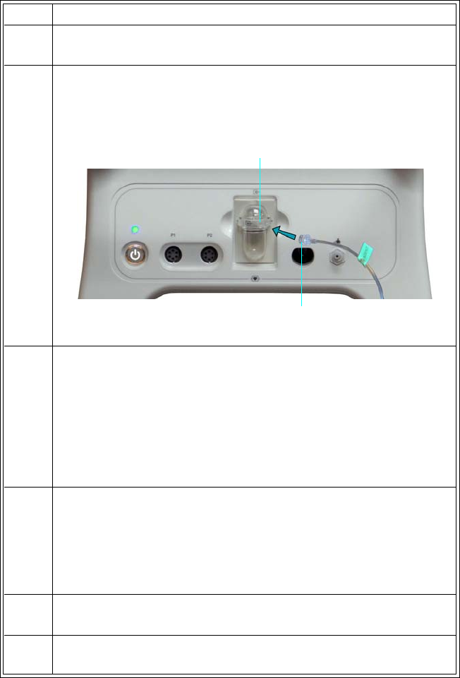
ExpressionMR400InstructionsforUseMonitoringAgentsandGases(AGENTOption)9‐7
TopreparetheAGENTtubing
Step Action
1Ensurethatthewatertraphasbeeninstalledinthewatertrap
receptacle(seepage9‐13forinstallationinstructions).
2InserttheLuerlockconnectoronthesamplingline(REF94018)
intothesampleportonthewatertrapandthentightenthe
connector(nomorethanonehalf‐turnshouldberequired).
3 AccordingthetypeofpneumaticcircuitrequiredtoperformAGENT
monitoring,connectthepneumaticcircuititems(seethediagrams
above).
WhereequippedwithaLuerlock,onlyahalf‐turnoftheLuerlock
connectorshouldberequiredwhereequipped;otherwise,ensure
thatanytubingconnectorhasbeenpressedfirmlyontothe
associatedadapter.
4Verifythateachconnectionistightbyholdingthenasalprongs(or
thepatientairwayadapter)closetoyourearandlisteningfora
hissingsound.
Increasetheflowtemporarilyifnecessaryandthenreducetothe
prescribedflowrateoncetheflowisverified.
5Onadailybasis,performasystemtest;seepage9‐8fordetails.
6Applythesamplinglinetothepatient(seepage9‐10).
Sample port
Sampling line

9‐8MonitoringAgentsandGases(AGENTOption) ExpressionMR400InstructionsforUse
WARNINGS
•Remove the sampling line from the patient airway whenever nebulized medications are
being delivered.
• Continuous exposure to waste anesthetic gases (including halogenated agents and
nitrous oxide) is not recommended. Always connect a line between the system’s waste
gas port and your facility’s gas scavenging/evacuation system. Avoid venting any waste
anesthetic gas directly into the room air as exposure to these gases above the
recommended OHSA limits could result.
• Do not block the waste gas port on the system. Ensure that the exhaust gas is not
removed from the system under too strong a vacuum. (To prevent this condition, there
must always be an opening to the room air.) Too high a vacuum level will change the
operating pressure of the system and cause inaccurate readings or internal damage.
• Use only approved sampling lines and AGENT accessories, as other sampling lines and
accessories will cause inaccurate readings and malfunctions.
• Replace the sampling line, replace the airway adapter, and inspect the water trap
between each patient use.
CAUTIONS
• Do NOT over-tighten the sampling line connection to the water trap; only a half-turn should
be needed. Over-tightening this connection may damage the water trap and cause failure of
the trap assembly.
• Regularly inspect the line to facility’s gas scavenging system for deterioration, and replace
the line if necessary.
Pre-Use System Checks
PriortousingthesystemforAGENTmonitoring,itisrecommendedthatthefollowinginitial
checksbeperformedatleastonce.
Step Action
1 Afterthepneumatictubinghasbeenpreparedasdirectedabove
(page9‐5),turnonthesystemandactivateAGENTintheMonitor
Setup>Parametersmenu;seepage3‐18.
IfAgentHWFail‐O2Sensorisdisplayedafteractivationofthe
parameter,replacetheO2sensorasdescribedonpage14‐13.
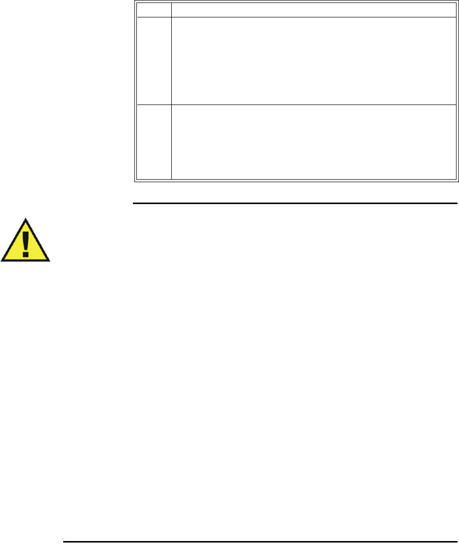
ExpressionMR400InstructionsforUseMonitoringAgentsandGases(AGENTOption)9‐9
WARNINGS
•Always test sampling line adapter for a tight connection and proper operation before
attaching to a patient. Over-tightening the sampling line connection may damage the
water trap. Tighten the sampling line connector no more than one half-turn. Over-
tightening this connector can cause failure of the water trap assembly and inaccurate
patient gas measurements.
• Inspect water trap and AGENT accessories before use. If the sampling line, connector
or sample port show signs of damage, replace the part immediately or discontinue use
and contact technical support. Never use damaged equipment.
• Frequently inspect the patient sampling line and keep it clear of any moving
mechanisms (for example, table wheels) which could cut, pinch, or dislodge the patient
tubing. Avoid kinking of the patient sampling line as leaks, reduced or stopped flow, or
internal venting of sampled gas into damaged tubing will cause inaccurate
measurements.
• Do not position the sampling line in any manner that may cause entanglement or
strangulation.
• Replace the sampling line if excessive secretions are observed, as inaccurate
measurements could result if the flow is reduced or stopped.
• Leakages in the breathing system or sampling system may cause the displayed
AGENT, CO2, O2, N2O values to be too low. Always connect all components securely
and check for leaks according to standard clinical procedures. Displacement of the
nasal cannula or patient airway adapter can cause lower than actual readings.
• If AGENT, CO2, O2, N2O values for patients who are not on a breathing circuit
appear extremely low, check whether the patient is breathing through the mouth or
whether one nostril is blocked.
2AllowtheAGSsystemtorunandsampleroomairforatleast1
minute.TheFiO2readingdisplayedintheGASVSboxshouldbe
approximately21percent.
Ifthereadingremainsoutsidethisrangeformorethan1minute
afterfirstcheckingthereading,replacetheoxygensensoras
describedinchapter14.
3 AfterallowingtheAGSsystemtorunforatleast1minute,pinchor
sealtheinputline(tothewatertrap)for5secondsandverifythat
Occlusionisdisplayed.
Ifthismessagedoesnotappear,checkalltubingconnectionsfor
leakageandretest.
Step Action
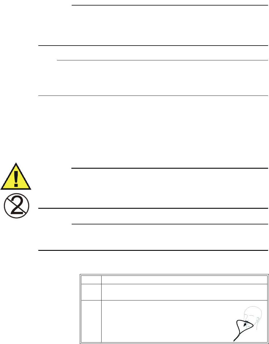
9‐10MonitoringAgentsandGases(AGENTOption) ExpressionMR400InstructionsforUse
CAUTION
Routinely inspect the hose assemblies for proper attachment and orientation. Replace hose
assemblies with cracks, holes, tears, or cuts that could cause leaks in the system. If hose
assemblies with damage that could result in leaks are used, prolonged and/or inaccurate patient
readings could result.
Note
Always inspect the patient sampling line after attachment to the MR400. If questionable anesthetic
agent gas measurements are observed, recheck the patient connections, the anesthesia gas
machine, and/or the vaporizer before readjusting anesthesia delivery.
Applying the Sampling Line to the Patient
SelecttheAGENTpatientaccessorythatisappropriateforthepatientsizeandapplication.
Patientnasalcannulasandsamplinglineswithanairwayadapterareintendedforusewith
breathingcircuitsandanesthesiacircuitsthathaveanintegratedairwayadapter.
WARNING
Patient sampling lines are intended for single-patient use only. Do not clean or disinfect these
items. Follow your hospital’s guidelines for appropriate disposal. Reuse of single-use devices
can result in spread of patient infection, degradation of monitoring performance, or
inaccurate measurements.
CAUTION
The accuracy of the data is greatly influenced by the proper use and fitting of the patient sampling
line to ensure proper sampling without the introduction of outside air.
Toapplythenasalcannulatothepatient
Step Action
1Ensurethatthenasalcannulaisclean,dryandundamaged.Replace
thecannulaifnecessary.
2 Positionthecannulaonthepatient’sfaceby
insertingthenasalprongsintothenostrils.
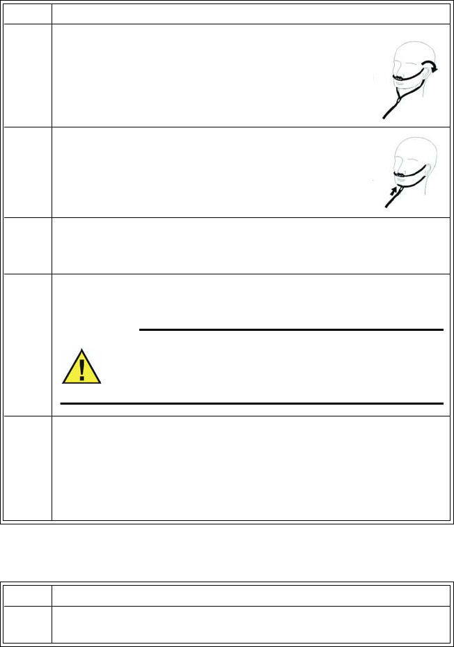
ExpressionMR400InstructionsforUseMonitoringAgentsandGases(AGENTOption)9‐11
Toapplythesamplinglineairwayadapter
3Passthetubingovertheearsandbehindthehead,
ensuringthepatient’sheadwillnotrestonanypart
ofthecannulawhilethepatientislyingdown.
4Slidethesleevetowardthepatient’sheadtoassurea
goodfitofthecannula.
5 SelectthePatientType.
SeeSelectingthePatientTypeonpage3‐11.
6Checkthattheconnectionshavebeenmadecorrectlybyverifying
thepatient’sbreathingeffortswiththedisplayedCO2waveform.
WARNING
Before completion of patient setup, ensure that the
patient’s breathing efforts coincide with the displayed
CO2 waveform.
7 AfterallowingtheAGSsystemtorunforatleast1minute,pinchor
sealthesamplinglinefor5secondsandverifythatOcclusionis
displayed.
Ifthismessagedoesnotappear,checkalltubingconnectionsfor
leakageandretest.
Step Action
1Ensurethatthesamplinglineisclean,dryandundamaged.Replace
thesamplinglineifnecessary.
Step Action

9‐12MonitoringAgentsandGases(AGENTOption) ExpressionMR400InstructionsforUse
2Placetheairwayadapterattheproximalendoftheairwaycircuit.
CAUTION
Always insert the patient sampling line into the water trap port
before inserting the airway adapter into the breathing circuit. Failure
to follow this may introduce a leak in the circuit, thereby reducing
set minute volume.
Note
Do not place the airway adapter between the ET tube and the elbow
as this may allow patient secretions to accumulate in the adapter. If
pooling does occur, replace the airway adapter. To prevent moisture
from draining into the airway adapter, always place the adapter
tubing in a up position, as shown above.
3 SelectthePatientType.
SeeSelectingthePatientTypeonpage3‐11.
4Checkthattheconnectionshavebeenmadecorrectlybyverifying
thepatient’sbreathingeffortswiththedisplayedCO2waveform.
WARNING
Before completion of patient setup, ensure that the
patient’s breathing efforts coincide with the displayed
CO2 waveform.
5 AfterallowingtheAGSsystemtorunforatleast1minute,pinchor
sealthesamplinglinefor5secondsandverifythatOcclusionis
displayed.
Ifthismessagedoesnotappear,checkalltubingconnectionsfor
leakageandretest.
Step Action
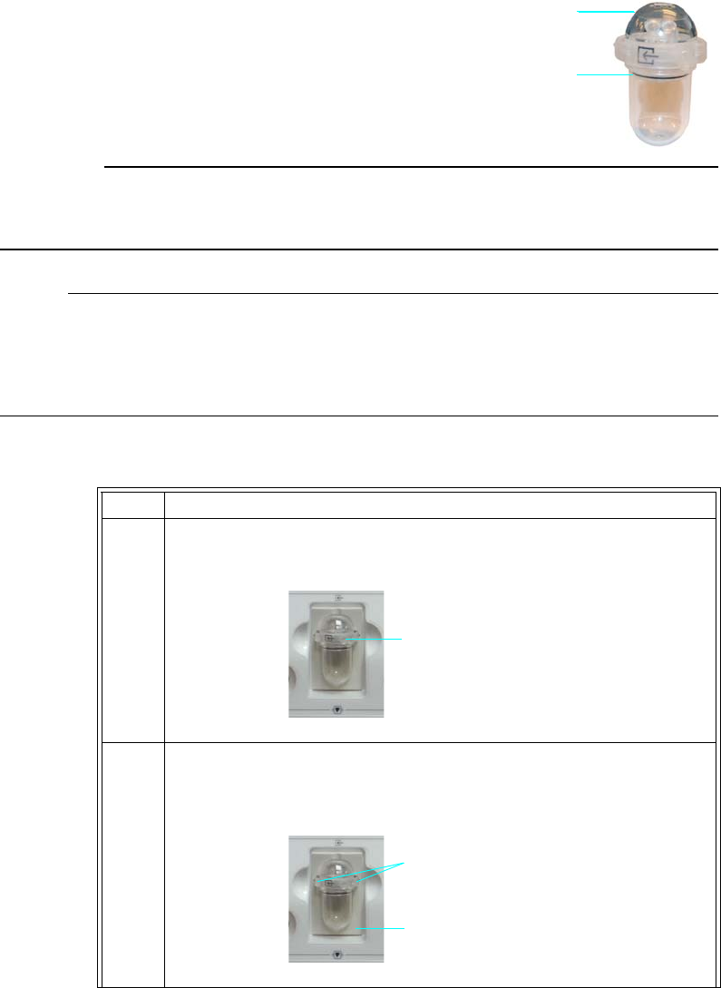
ExpressionMR400InstructionsforUseMonitoringAgentsandGases(AGENTOption)9‐13
Water Trap Replacement
Thewatertrapisintendedtoprotectthe
AGENTsystemfromhumidity,secretions,
bacterialcontaminationanddust.Replacement
ofthewatertrapisnecessarywhenthe
contentsinthewatertrapreachitsfullline.
CAUTION
Always discard the water trap when it becomes filled. Do not attempt to clean or reuse the water
trap. Accidental water ingress into the system can affect the gas measurements.
Notes
• The water trap must be checked every 17 hours of use and replaced as necessary. (Dispose
of the trap according to your facility’s biohazard procedure.)
• For optimum fit and compatibility, use only Invivo (Royal Philips) specified parts.
Toreplacethewatertrap
Step Action
1
Ifasamplinglineisconnected,thenremovethesamplinglinefromthe
sampleportonthewatertrap.
2Whilesimultaneouslypressingbothreleasetabsonthewatertrap,
removethewatertrapfromthewatertrapreceptaclethendisposeof
thewatertrapproperly.
Full line
Water trap
Sample port
Release tabs
Water trap receptacle
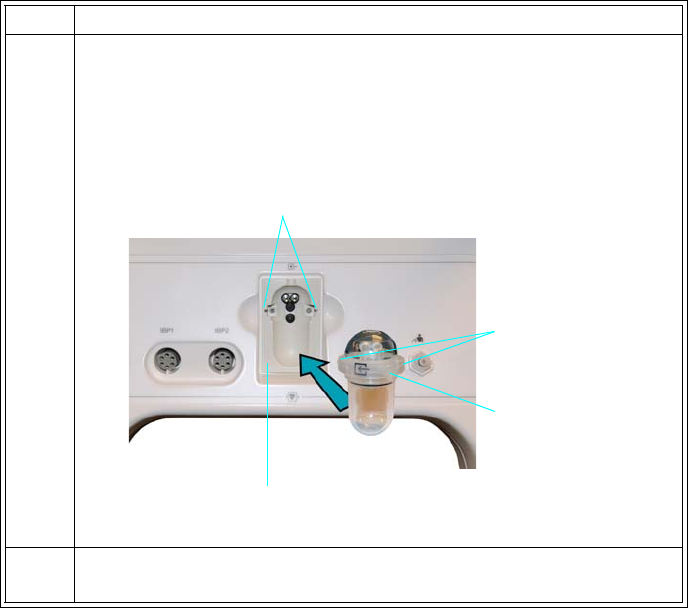
9‐14MonitoringAgentsandGases(AGENTOption) ExpressionMR400InstructionsforUse
AGENT and GAS VS Boxes
AGENToptionmeasurementsaredisplayedinseveralareas:
• Primaryandsecondaryagentgasmeasurementsaredisplayedasnumericinformationin
theAGENTVSbox.
•N2O,O2,andMACmeasurementsaredisplayedasnumericinformationintheGASVSbox.
•CO2measurementsaredisplayedasawaveformintheVStraceareaofthescreenandas
numericinformationintheCO2VSbox—wheredependingupontheRESP>Source
setting,CO2‐derivedrespirationinformationmayappearintheRESPVSbox.
3Withthenewwatertrappositionedsothatthesampleportisfacing
towardyou,alignthetrap’sreleasetabstothereleasetabslotsinthe
watertrapreceptacle.Pressthewatertrapintothewatertrap
receptacleuntilaudible“clicks”areheardasbothofthereleasetabs
lockintothereleasetabslots.
4 Attachthesamplinglinetothesampleport.
Step Action
Release tabs
Release tab slots
Water trap receptacle
Sample port
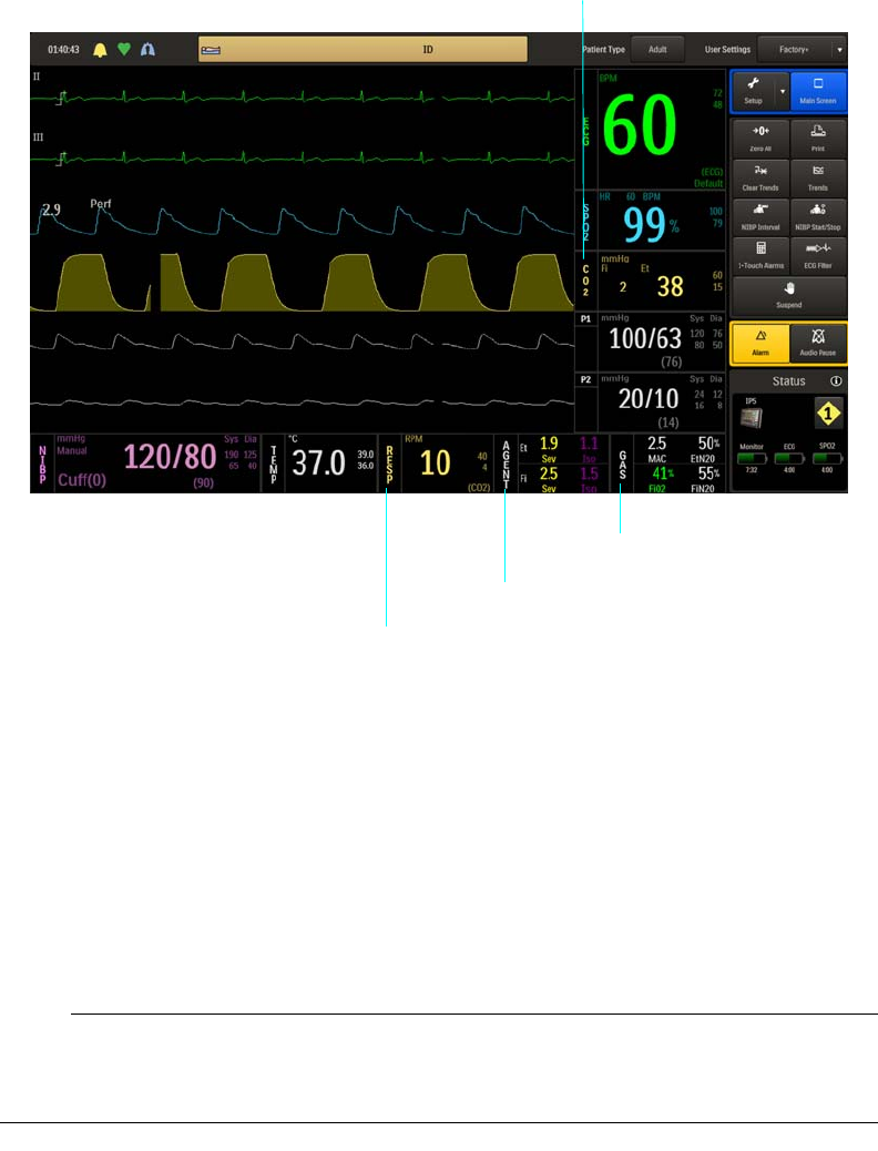
ExpressionMR400InstructionsforUseMonitoringAgentsandGases(AGENTOption)9‐15
Multiple (Mixed) Agents
Whenevertwoormoreanestheticagentgasesofdetectableconcentrationsaresensedbythe
AGSsystemorwhentheagentgasesintheinspiredandend‐tidalbreathphasesarepurebut
differfromoneanother,amultipleagentsconditionexistsandMultipleAgentswillbedisplayed.
Itiscommonforamultipleagentsconditiontooccurduringthetransitionfromoneanesthetic
agenttoanother,suchaswhenoneagentisusedtoinduceapatientandanotheragentisused
tomaintainthesedatedstate.
Note
Some hydrocarbons (for example, acetone or methane) will cause a Multiple Agents alarm to
occur.
AGENT VS box
GAS VS box
CO2 VS box
RESP VS box
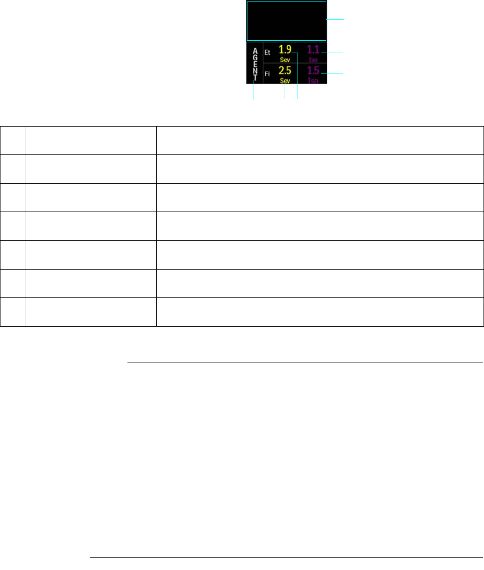
9‐16MonitoringAgentsandGases(AGENTOption) ExpressionMR400InstructionsforUse
AGENT VS Box
*Valuesdisplayedtothenearest0.1percent
Notes
• No data indication is denoted by three dashes (---) in the agent measurement numeric values
(see page 2-20 for an example). When the agent vaporizer is first turned on, it may take 30–
90 seconds for agent identification and readings to be displayed. Once identification is
established, changes in concentration readings are virtually immediate.
• With a 200 percent change in concentration, an auto zero will occur and full accuracy of
the changed concentration will be accomplished within approximately 30 seconds.
• For the identified agent gases, these abbreviations (and colors) are used:
– Desflurane – Des (light blue)
– Enflurane – Enf (orange)
– Halothane – Hal (pink)
– Isoflurane – Iso (purple)
– Sevoflurane – Sev (yellow)
1
64
5
2
3
Item Name Definition
1 Alarm flag area Displays AGENT alarm flags when detected; see page 4-31.
2 Secondary agent Et numeric Is the patient’s detected concentration and type of secondary end-tidal agent, in
volume percent *
3 Secondary agent Fi numeric Is the patient’s detected concentration and type of secondary fractional inspired
agent, in volume percent *
4 Primary agent Et numeric Is the patient’s detected concentration and type of primary end-tidal agent, in
volume percent *
5 Primary agent Fi numeric Is the patient’s detected concentration and type of primary fractional inspired
agent, in volume percent *
6 AGENT VS box label Indicates the Agent parameter, and accesses the MAC window
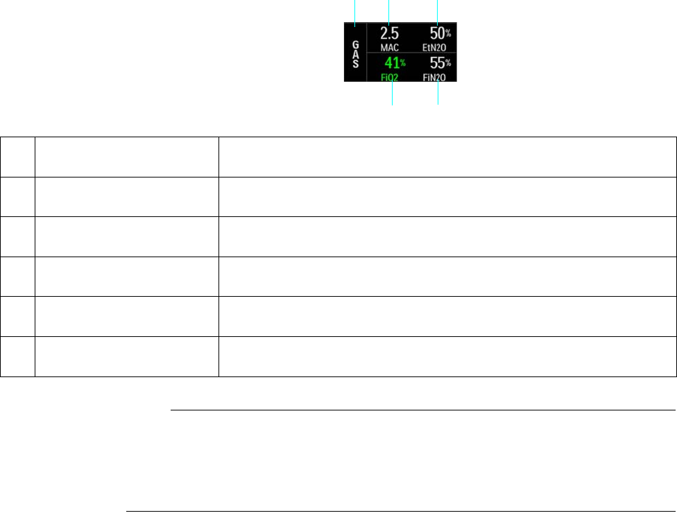
ExpressionMR400InstructionsforUseMonitoringAgentsandGases(AGENTOption)9‐17
GAS VS Box
Note
No data indication is denoted by three dashes (---) in the numeric values (see page 2-20 for an
example). When AGENT is turned on, it may take 30–90 seconds for gases identification and
readings to be displayed. Once identification is established, changes in concentration readings
will be virtually immediate.
Changing the AGENT and GAS Alarm Limits
TheGasAlarmsmenucanbeaccessedbytouchingtheSetupkeyandthentheAlarmskey.On
theAlarmsmenu,selecttheGasAlarmsbutton.
12
4
3
5
Item Name Definition
1GAS VS box label Indicates the gas parameter
2 MAC numeric Is the total MAC value (see MAC Window on page 9-20)
3 EtN2O numeric Is the patient’s detected end-tidal nitrous oxide concentration in percent
4 FiN2O numeric Is the patient’s detected fractional inspired nitrous oxide concentration in
percent
5 FiO2 numeric Is the patient’s detected fractional inspired oxygen concentration in percent
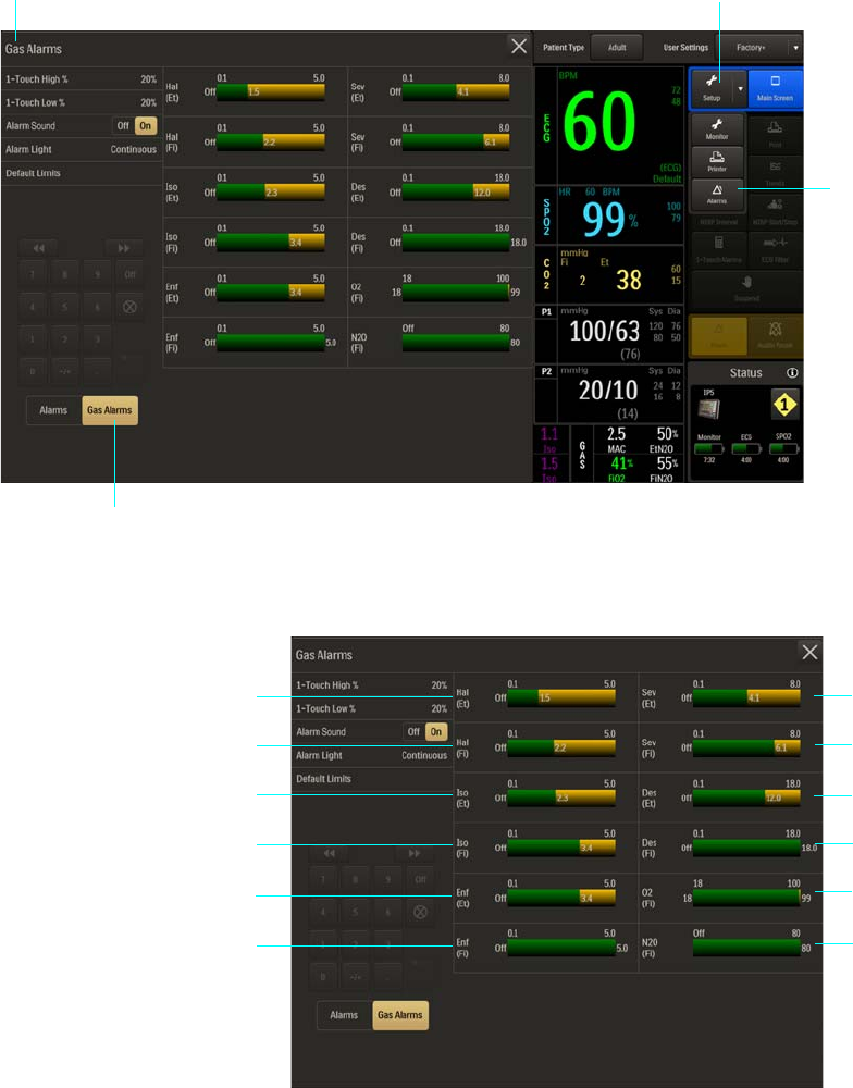
9‐18MonitoringAgentsandGases(AGENTOption) ExpressionMR400InstructionsforUse
Lowerandupperalarmlimitsettingsforagentsandgasesareillustratedbelow.
Gas Alarms menu Setup key
Alarms key
Gas Alarms button
1Sev (Et) – (Sevoflurane [End-tidal])
2Sev (Fi) – (Sevoflurane [Fractional inspired])
3Des (Et) – (Desflurane [End-tidal])
4Des (Fi) – (Desflurane [Fractional inspired])
1
2
3
4
5
6
7
8
9
10
11
12
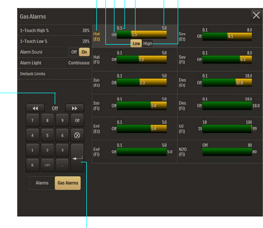
ExpressionMR400InstructionsforUseMonitoringAgentsandGases(AGENTOption)9‐19
Individualalarmlimitsettingscanbeadjustedbyselectingtheparameterthatyouwantto
changeontheGasAlarmsmenu.
5O2 (Fi) – (Oxygen [Fractional inspired])
6N2O (Fi) – (Nitrous oxide [Fractional inspired])
7Enf (Fi) – (Enflurane [Fractional inspired])
8Enf (Et) – (Enflurane [End-tidal])
9Iso (Fi) – (Isoflurane [Fractional inspired])
10 Iso (Et) – (Isoflurane [End-tidal])
11 Hal (Fi) – (Halothane [Fractional inspired])
12 Hal (Et) – (Halothane [End-tidal])
1Agent or gas alarm limits label (active adjustment shown)
2Low button
3Lower alarm limit setting
4Alarm limit, minimum
5Upper alarm limit setting
6Alarm limit, maximum
7High button
13257
8
9
64

9‐20MonitoringAgentsandGases(AGENTOption) ExpressionMR400InstructionsforUse
TochangeanindividualalarmlimitsettingintheGasAlarmsmenu
Note
See chapter 4 for detailed alarm limit setting instructions and options.
MAC Window
DetectedanestheticvaporstrengthsoftheexpiredgasescontributetotheMAC(Minimum
AlveolarConcentration)valueandareprovidedintheMACwindow.
8Enter button
9Current adjustment
Step Action
1Touchtheagentorgasparameterthatyouwanttochangeonthe
GasAlarmsmenu.
Theselectionappearsonahighlightedbackground.(HAL[Et]was
selectedforthisexample.)Currentsettingsaredisplayed.
2 SelecttheLowbuttonortheHighbutton.
Theselectedbuttonwillbehighlightedandthecurrentadjustment
willbedisplayed.
3Usingthekeypad,ortheincrement,decrement,orOffbuttons,
enterthedesiredsetting.
Thecurrentadjustmentwillreflectthesetting.
4Press
theEnterbuttontosavethesetting.
Thealarmlimitsettingisupdated.
5Tochangetheremainingsetting,repeatsteps2,3,and4.
Thecurrentadjustmentwillreflectthechange.
6Tochangeanyremainingalarmlimitsettings,repeatsteps1,2,3,
and4.
7PresstheMainScreenkeytoclosethemenu.
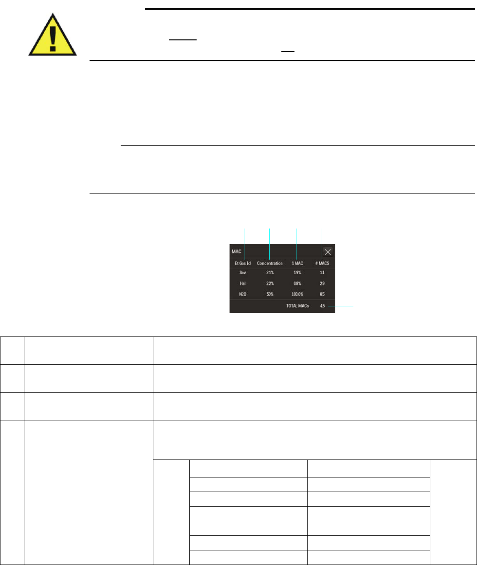
ExpressionMR400InstructionsforUseMonitoringAgentsandGases(AGENTOption)9‐21
WARNING
MAC values are empirical, not absolute values. The MAC values correspond to those of
healthy adults and cannot be applied to children. Age and other individual factors
influencing the behavior of volatile agents are not taken into account.
ToopentheMACwindow
SelecttheAGENTortheGASVSbox(seepage9‐14forthelocation).
Note
If AGENT is set to Single in the System Config menu, the MAC window will display Mixed
Agents Not Included In MAC Calculation.
2
5
34
1
Item Name Definition
1 Et Gas Id Is the identifier for the given end-tidal gas
2 Concentration Is the current concentration of the given gas, in percent
3 1 MAC Is the minimum alveolar concentration for the given gas at which 50 percent of a
patient population does not respond with movement to a noxious stimulus, such
as skin incision; see table below.
Gas 1 MAC Value
DES (Desflurane) 6.00 volume%
ENF (Enflurane) 1.70 volume%
HAL (Halothane) 0.77 volume%
ISO (Isoflurane) 1.15 volume%
SEV (Sevoflurane) 2.10 volume%
N2O (Nitrous oxide) 105 percent
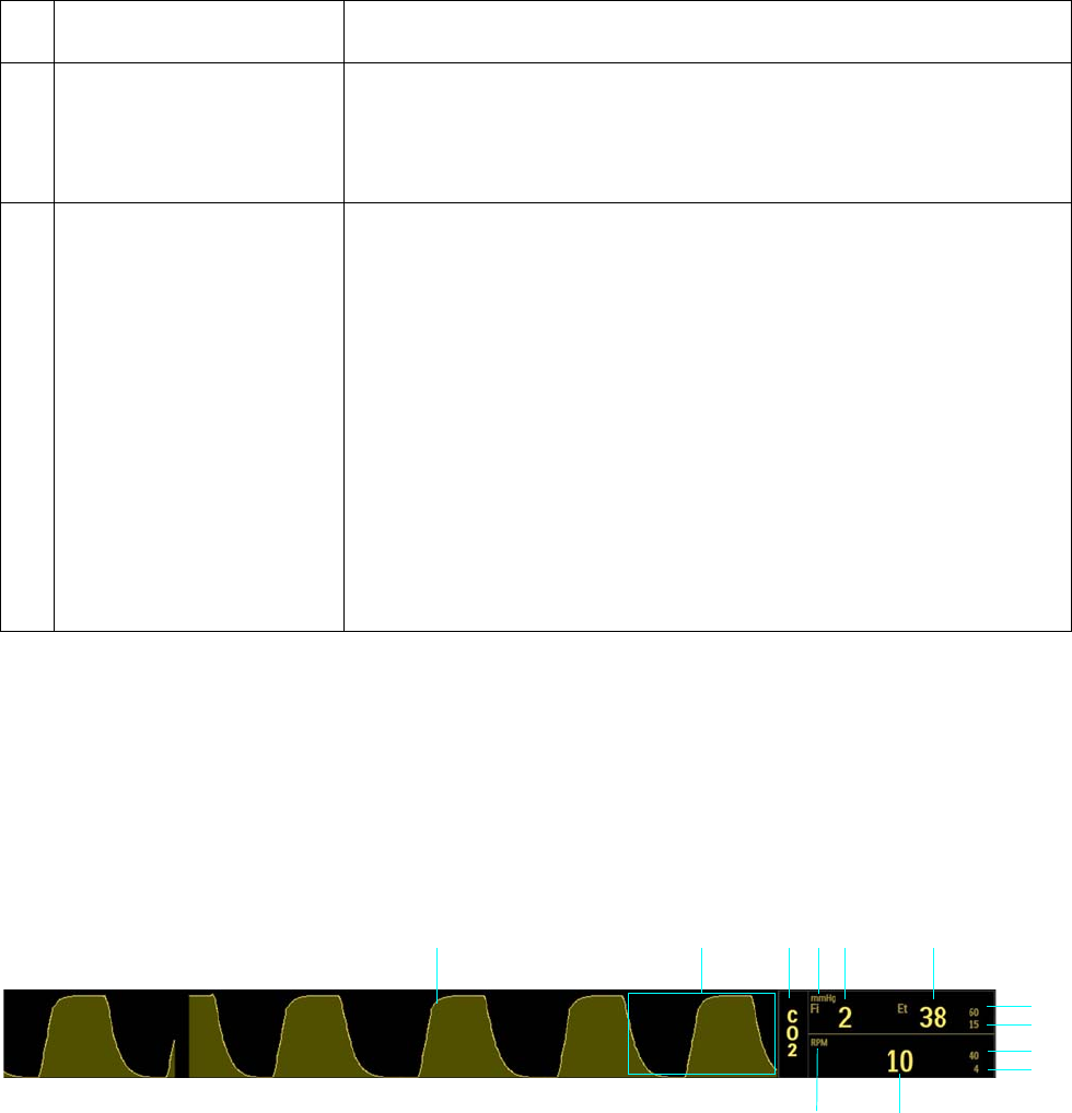
9‐22MonitoringAgentsandGases(AGENTOption) ExpressionMR400InstructionsforUse
CO2 Waveform and VS Box
TheCO2measurementisdisplayedasawaveformintheVStraceareaofthescreenandas
numericinformationintheCO2VSbox.Otherdata,includingCO2‐relatedalarminformation,are
alsoprovidedinthisareaofthescreen.(CO2[RESP]informationcanbedisplayedintheCO2VS
boxorintheRESPVSbox,asdetailedbelow.)
4 # MAC Is the MAC value that each individual gas contributes to the total MAC value,
calculated by C/M, where:
C = the current concentration of the given gas
M = the 1 MAC value for the given gas
5 TOTAL MACs Is the total MAC value, which is equal to the sum of the values in the # MAC
column, calculated using the following formula:
TOTAL MAC = EtN2O / (1 MAC N2O) +
(Et 1st Agt) / (1 MAC 1st Agt) +
(Et 2nd Agt) / (2 MAC 2nd Agt)
Where:
•EtN
2O = The current value of end-tidal nitrous oxide
•1 MAC N
2O = The 1 MAC value for nitrous oxide
•Et 1
st Agt = The current concentration of the primary agent gas
•Et 2
nd Agt = The current concentration of the secondary agent gas
•1 MAC 1
st Agt = The 1 MAC value for the current primary agent gas
•2 MAC 2
nd Agt = The 2 MAC value for the current secondary agent gas
Item Name Definition
7
13456
11
8
9
10
2
12

ExpressionMR400InstructionsforUseMonitoringAgentsandGases(AGENTOption)9‐23
Changing the CO2 and CO2 (RESP) Alarm Limits
TheCO2(Et)andCO2(Fi)AlarmLimitsmenucanbeaccessedbytouchingthealarmlimitsettings
intheCO2VSbox.
Item Name Definition
1 CO2 VS waveform Is the detected CO2 waveform (Trace D)
Note
To change the waveform speed, see Resp Speed on page 3-25.
2 Alarm flag area Displays CO2 alarm flags when detected; see page 4-31.
3CO2 VS box label Indicates the CO2 vital sign parameter, and accesses the CO2 menu
4 Unit of measure Indicates that the gas measurement numeric values are given in mmHg
(millimeters of mercury) or kPa (kilopascals); see page 9-26.
5 FiCO2 numeric Is the patient’s detected fractional inspired CO2 measurement
6 EtCO2 numeric Is the patient’s detected end-tidal CO2 measurement
7 EtCO2 upper alarm limit Is the upper limit setting for the end-tidal CO2 alarm, and accesses the CO2
(Et) Alarm Limits menu
8 EtCO2 lower alarm limit Is the lower limit setting for the end-tidal CO2 alarm, and accesses the CO2
(Et) Alarm Limits menu
9Respiration rate upper alarm
limit
Is the upper limit setting for CO2-derived respiration rate alarm, and accesses
the CO2 (RESP) Alarm Limits menu
10 Respiration rate lower alarm
limit
Is the lower limit setting for CO2-derived respiration rate alarm, and accesses
the CO2 (RESP) Alarm Limits menu
11 Respiration rate numeric Is the patient’s detected respiration rate measurement, as derived from CO2
12 Unit of measure Indicates that the respiration rate numeric is given in RPM (respirations per
minute)
When Source is set to BEL in the RESP menu (see page 10-5), the CO2 VS box will also contain CO2-derived respiration rate
elements, as indicated by the shaded rows and illustration above; otherwise, this information will be displayed in the RESP VS box
(see page 9-25).
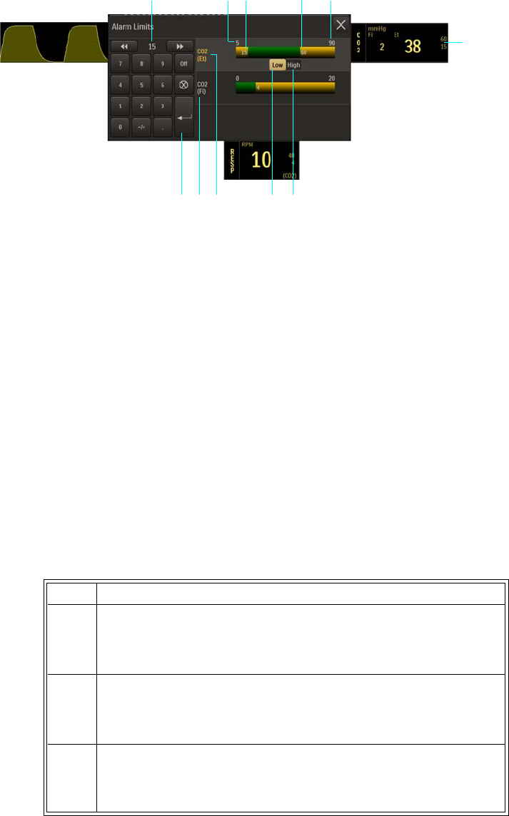
9‐24MonitoringAgentsandGases(AGENTOption) ExpressionMR400InstructionsforUse
TochangetheCO2(Et)andCO2(Fi)alarmlimitsettings
1Alarm limit settings, CO2 (Et), CO2 VS box
2High button
3Low button
4 CO2 (Et) Alarm Limits menu label (active adjustment shown)
5CO2 (Fi) Alarm Limits menu label
6Enter button
7Current adjustment
8Alarm limit, minimum
9Lower alarm limit setting
10 Upper alarm limit setting
11 Alarm limit, maximum
Step Action
1 Selectthe(Et)CO2alarmlimitsettingsintheCO2VSbox.
TheCO2AlarmLimitsmenuappears.CurrentCO2(Et)settingsare
displayed.
2 SelecttheCO2alarmlimitsmenu,CO2(Et)orCO2(Fi),thatyou
wanttochange.
Theassociatedmenuappears.Currentsettingsaredisplayed.
3 SelecttheLowbuttonortheHighbutton.
Theselectedbuttonwillbehighlightedandthecurrentadjustment
willbedisplayed.
1
2
7
3456
8 9 10 11
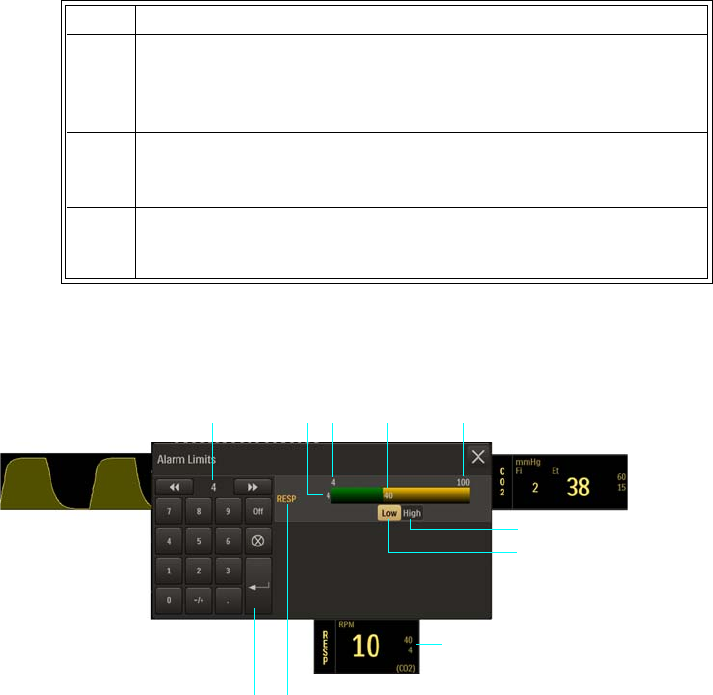
ExpressionMR400InstructionsforUseMonitoringAgentsandGases(AGENTOption)9‐25
Atthedefaultsetting,theCO2(RESP)AlarmLimitsmenucanbeaccessedbytouchingthealarm
limitsettingsintheRESPVSbox.
4Usingthekeypad,ortheincrement,decrement,orOffbuttons,
enterthedesiredsetting.
Thecurrentadjustmentwillreflectthesetting.
5PresstheEnterbuttontosavethesetting.
Thealarmlimitsettingisupdated.
6
Tochangetheremainingsettings,repeatsteps2–5.
Thecurrentadjustmentwillreflectthechange.
1High button
2Low button
3Alarm limit settings, CO2 (RESP), RESP VS box
4CO2 (RESP) Alarm Limits menu label
5Enter button
6Current adjustment
7Lower alarm limit setting
8Alarm limit, minimum
9Upper alarm limit setting
10 Alarm limit, maximum
Step Action
1
2
6
3
45
7 8 9 10

9‐26MonitoringAgentsandGases(AGENTOption) ExpressionMR400InstructionsforUse
TochangetheCO2(RESP)alarmlimitsettings
Note
See chapter 4 for detailed alarm limit setting instructions and options.
Changing the Unit of Measure
Tochangetheunitofmeasure
Step Action
1 SelecttheCO2(RESP)alarmlimitsettingsintheRESPVSbox(or,in
theCO2VSbox,seepage9‐22.)
TheCO2(RESP)AlarmLimitsmenuappears.Currentsettingsare
displayed.
2 SelecttheLowbuttonortheHighbutton.
Theselectedbuttonwillbehighlightedandthecurrentadjustment
willbedisplayed.
3Usingthekeypad,ortheincrement,decrement,orOffbuttons,
enterthedesiredsetting.
Thecurrentadjustmentwillreflectthesetting.
4PresstheEnterbuttontosavethesetting.
Thealarmlimitsettingisupdated.
5
Tochangetheremainingsetting,repeatsteps2,3,and4.
Thecurrentadjustmentwillreflectthechange.
Step Action
1PresstheSetupkeyandthentheMonitorkey.
TheMonitorSetupmenuappears.Currentsettingsaredisplayed.
2OntheMonitorSetupmenu,selectService(Bio‐Med).
TheService(Bio‐Med)sub‐menuappears.
3OntheService(Bio‐Med)menu,selectSystemConfig.
TheSystemConfigmenuappears.Currentsettingsaredisplayed.
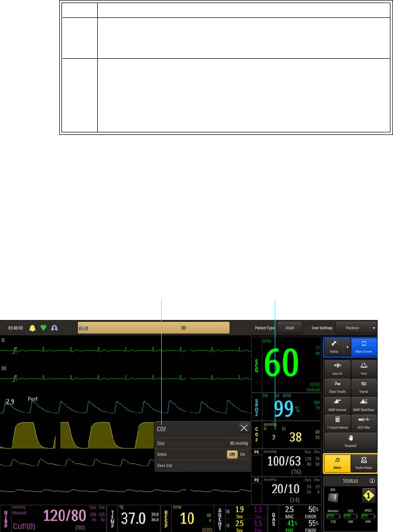
ExpressionMR400InstructionsforUseMonitoringAgentsandGases(AGENTOption)9‐27
CO2 Menu
TheCO2menuallowsyoutocontroltheCO2(Et)andCO2(RESP)monitoringfunctionsand
settings.
ToopentheCO2menu
SelecttheCO2VSbox.
4OntheSystemConfigmenu,selectGasUnits.
TheGasUnitsmenuappears.Thecurrentsettingishighlighted.
5 Selectthedesiredunitofmeasure:
mmHg
kPa
Thesettingischanged.
Step Action
CO2 VS box CO2 menu
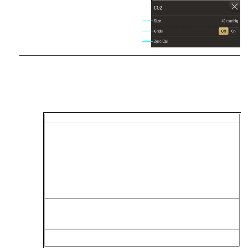
9‐28MonitoringAgentsandGases(AGENTOption) ExpressionMR400InstructionsforUse
ThefollowingCO2menuitemsareavailable:
Note
Apnea and Apnea Time will be in the CO2 menu when bellows (BEL) is the selected RESP >
Source; see page 10-7 for setting details.
TochangesettingsintheCO2menu
Size
ControlsthesizeoftheCO2waveform.
Thefollowingoptionsareavailable:
•40mmHg(Default)
•60mmHg
•80mmHg
1Size
2Grids
3Zero Cal
Step Action
1 SelecttheCO2VSbox.
TheCO2menuappears.Currentsettingsaredisplayed.
2TouchthemenuitemtoselectoneofthefollowingCO2options:
Size
Grids
ZeroCal
Themenuitemappears.Thecurrentsettingishighlighted.
3 Selectthedesiredsettingfromthemenuoptions(exceptGrids,
whichisselectableontheCO2menu).
Thesettingisentered.
4Tochangeothersettings,repeatsteps2and3.
2
3
1
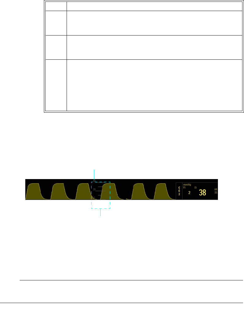
ExpressionMR400InstructionsforUseMonitoringAgentsandGases(AGENTOption)9‐29
ToadjustthegridsizefortheCO2waveform
Grids
Displaysascaledgrid,whichisgraduatedaccordingtotheSizeselectionfortheCO2waveform.
Thefollowingoptionsareavailable:
•Offdoesnotdisplayagrid.(Default)
•Ondisplaysagrid.
Note
Grids will not be displayed during a CO2 Accuracy Check; see page 3-30.
Step Action
1 SelecttheCO2VSbox.
TheCO2menuappears.Currentsettingsaredisplayed.
2 SelectSize.
TheSizemenuappears.Thecurrentsettingishighlighted.
3 Selectthedesiredsize:
40mmHg
60mmHg
80mmHg
Thesettingischanged.
Grid
Size

9‐30MonitoringAgentsandGases(AGENTOption) ExpressionMR400InstructionsforUse
TocontrolthedisplayfunctionoftheCO2grid
Zero Cal
Initiatesazerocalibration(anautomaticfunctionduringnormaluse)oftheCO2systemtoallow
forthedifferentcharacteristicsofeachaccessorytype.ZeroCalisnotrequiredwhenswitching
samplinglines.Themaximumtimerequiredforcalibrationisapproximately10–12seconds.
Toperformazerocalibration
Seepage9‐2.
Step Action
1 SelecttheCO2VSbox.
TheCO2menuappears.Currentsettingsaredisplayed.
2LocateGridsandselectthedesiredsetting:
Off
On
Thesettingisentered.

ExpressionMR400InstructionsforUseMonitoringRESP10‐1
CHAPTER 10
Monitoring RESP
WhenequippedwiththeCO2orAGENToption,thepatient’srespirationratecanbemeasuredas
thetimeintervalbetweendetectedbreaths.Alternatively,thepatient’srespirationratecanbe
measuredusingthepneumaticbellowsandthewSpO2module.
Patient Preparation for RESP Monitoring
Whenpreparingapatient,themonitoringmethodusedwillimpacttheperformanceand
operationoftheRESPparameter.
Monitoring Respiration using CO2
CO2‐derivedrespirationiscalculatedbymeasuringthetimeintervalbetweendetectedbreaths;
seechapter7(ifequippedwiththeLoFlooption)orchapter9(ifequippedwiththeAGENT
option)fordetailedmonitoringinformation.ForRESPVSboxfunctionswhenCO2‐derived
respirationisthesource,seepage10‐3.
Monitoring Respiration using the Bellows
Bellows‐derivedrespirationismonitoredbydetectingabdominalorchestwallmotionusingthe
pneumaticbellowsdevice(REF989803152791)andthewSpO2module.
ThebellowsmaybeusedintheMRsystembore,althoughthemodulemustnotbeplacedwithin
theMRsystembore.Notethattherearenoalarmsforthebellows‐derivedrespirationrateasit
isnotintendedforvitalsignmonitoring.
CAUTION
If dropped, the wSpO2 module must be verified for correct operation before use; see page 14-12.
Note
If bellows respiration is turned on while the CO2 is on, bellows respiration rate data will appear
in the RESP VS box and CO2 respiration rate data will appear in the CO2 VS box.
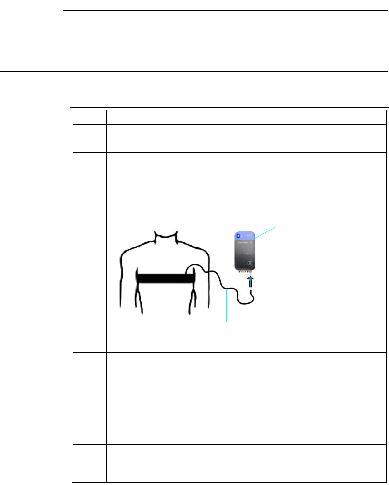
10‐2MonitoringRESPExpressionMR400InstructionsforUse
Bellows Preparation
Respirationmeasurementsthataredeterminedusingthebellowsmethodmakechestwall
expansionveryimportantforaccuratemonitoringofapatient’sbreathing.Iftherespiratory
signalappearstoweakenbetweenscans,instructthepatienttobreathemoredeeplyduringthe
scantocreatemoremovementatthesensorsite.
CAUTIONS
• Avoid excessive bending of the flexible hose, as this can impair respiration detection.
• Always apply the bellows to the patient prior to connecting the pneumatic respiration hose
to the port on the wSpO2 module; otherwise damage to the module can result.
Topositiontherespiratorysensor
Step Action
1Placethesensoronthepatient’supperabdomenorlowerchest
(whicheverexpandsmostduringinspiration).
2 Afterthepatienthasexhaled,placethevelcrostraparoundthe
patient’strunkandsecurethesensorsnuggly.
3Connecttheflexiblehosefromthebellowstothepneumatic
respirationportonthewSpO2module.
4CheckthebatteryindicatoronthewSpO2moduletoensurethat
enoughchargeexists:
• Greenbatteryindicator=Chargesufficient;proceedtostep6.
•Redbatteryindicator=Chargelow;proceedtostep5.
Seepage2‐11fordetails.(Also,youcanreferencethestatus
informationpane;seepage2‐16.)
5InsertachargedmodulebatteryintothewSpO2moduleandthen
recheckthebatteryindicatortoensureasufficientchargebefore
proceeding;seepage1‐26.
Pneumatic
respiration port
wSpO2 module
Flexible hose
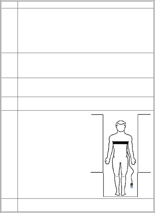
ExpressionMR400InstructionsforUseMonitoringRESP10‐3
Respiration VS Box
DependingupontheSourceselection,respirationmeasurementsaredisplayedasnumeric
informationintheRESPVSbox.Otherdata,includingrespiration‐relatedalarminformation,are
alsoprovidedinthisareaofthescreen,asdetailedbelow.
6CheckthenetworkchannelindicatoronthewSpO2moduleto
ensurecommunicationisestablishedwiththeMR400:
• Steady=Goodcommunication;proceedtostep7.
• Flashing=Nocommunication;proceedtostep6.
Seepage2‐11fordetails.(Also,youcanreferencethestatus
informationpane;seepage2‐16.)
7EnsurethatthewSpO2moduleiswithin9.1m(30feet)ofthe
MR400,inthesameMRIroomorinthesameshieldedroom,andis
settothesamewirelessnetworkchannelusedbytheMR400;see
page1‐29.
8 SelectthePatientType.
SeeSelectingthePatientTypeonpage3‐11.
9Ensurethattheparameterisworkingbycheckingthedisplayed
respiratorynumericintheVSbox.
10 PositionthepatientintheMR
system,keepingthewSpO2
moduleoutsidetheMR
systembore.Ensurethatthe
flexiblehoseisroutedaway
fromanymovingpartssothat
itdoesnotgetcaughtinthe
mechanisms(forexample,
betweenthetabletopandthe
patientsupport).
11 PlacethewSpO2moduleonacushionedsurfacetominimizeMR
vibrations.
Step Action
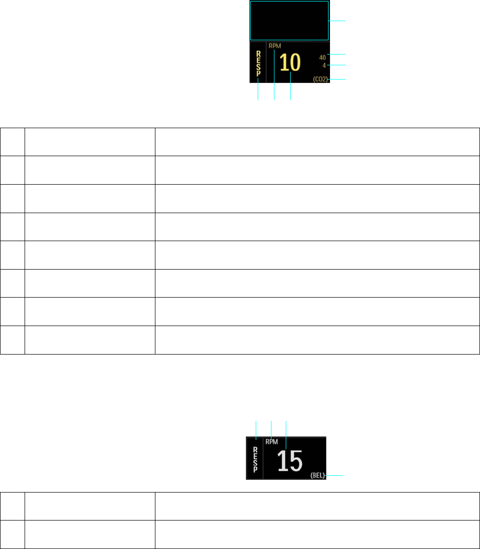
10‐4MonitoringRESPExpressionMR400InstructionsforUse
•WhenRESP>Source>CO2isselected,theCO2‐derivedrespirationmeasurementand
alarmlimitsettings(displayedinthesamecolorastheCO2VSboxdata)willpopulatethe
RESPVSbox.
•WhenRESP>Source>BELisselected,thebellows‐derivedrespirationmeasurement
(displayedinwhite)willpopulatetheRESPVSbox.
5
2
3
4
1
6
7
Item Name Definition
1 Alarm flag area Displays CO2 (RESP) alarm flags when detected; see page 4-31.
2 Respiration rate upper alarm
limit
Is the upper limit setting for the CO2 (RESP) alarm, and accesses the CO2
(RESP) Alarm Limits menu (when Source isCO2)
3 Respiration rate lower alarm
limit
Is the lower limit setting for the CO2 (RESP) alarm, and accesses the CO2
(RESP) Alarm Limits menu (when Source isCO2)
4 Source label Is the source used for the respiration monitoring, where CO2 is CO2-derived;
see page 10-7
5 Respiration rate numeric Is the patient’s detected respiration rate measurement
6 Unit of measure Indicates that the respiration rate numeric is given in RPM (respirations per
minute)
7 RESP VS box label Indicates the respiration vital sign parameter, and accesses the RESP menu
123
4
Item Name Definition
1 RESP VS box label Indicates the respiration parameter, and accesses the RESP menu

ExpressionMR400InstructionsforUseMonitoringRESP10‐5
Changing the CO2 (RESP) Alarm Limits
TochangetheCO2(RESP)alarmlimitsettings:
•IfequippedwiththeCO2LoFlooption,seepage7‐9.
•IfequippedwiththeAGENToption,seepage9‐23.
RESP Menu
RESPmenuitemsallowyoutocontrolrespirationfunctionsandsettings.
ToopentheRESPmenu
SelecttheRESPVSbox.
2 Unit of measure Indicates that the respiration rate numeric is given in RPM (respirations per
minute)
3 Respiration rate numeric Is the patient’s detected respiration rate measurement
4 Source label Is the source used for the respiration monitoring, where BEL is bellows-derived;
see page 10-7
Item Name Definition
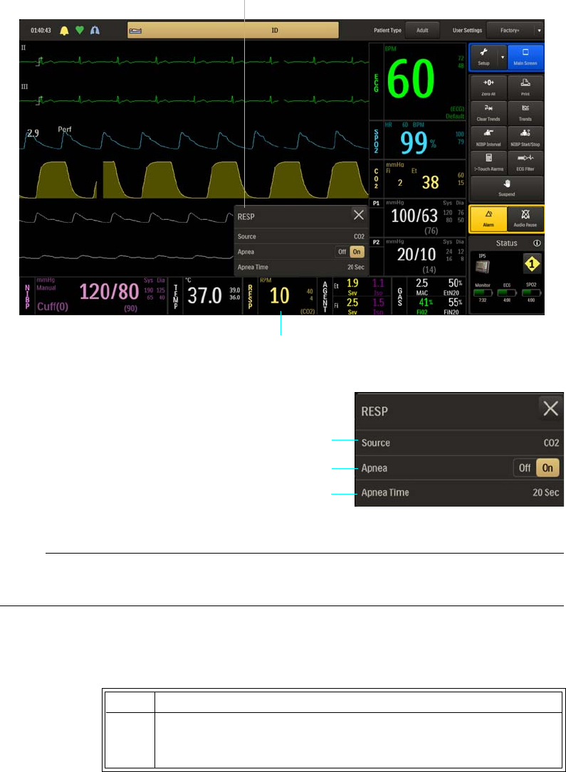
10‐6MonitoringRESPExpressionMR400InstructionsforUse
ThefollowingRESPmenuitemsareavailable:.
Note
If RESP > Source > BEL, then Apnea and Apnea Time will be in the CO2 menu.
TochangesettingsintheRESPmenu
1Source
2Apnea
3Apnea Time
Step Action
1 SelecttheRESPVSbox.
TheRESPmenuappears.Currentsettingsaredisplayed.
RESP menu
RESP VS box
1
2
3

ExpressionMR400InstructionsforUseMonitoringRESP10‐7
Source
SelectsthesourceusedtoacquiretherespirationratemeasurementsdisplayedtheRESPVSbox.
Thefollowingoptionsareavailable:
•CO2calculatestheratebymeasuringthetimeintervalbetweendetectedbreaths.
(Default,whenequippedwiththeCO2orAGENToption)
•BELcalculatestherateusingapneumaticbellowsthatmeasureschestorabdominal
movement.Nowaveformisprovided.(IfequippedwiththeCO2orAGENToption,thenthe
CO2respirationrateelementswillappearintheCO2VSbox.)
Tocontrolthesourceusedforrespiration
2TouchthemenuitemtoselectoneofthefollowingRESPoptions:
Source
Apnea
ApneaTime
Themenuitemappears.Thecurrentsettingishighlighted.
3 Selectthedesiredsettingfromthemenuoptions(exceptApnea,
whichisselectableontheRESPmenu).
Thesettingisentered.
4Tochangeothersettings,repeatsteps2and3.
Step Action
1 SelecttheRESPVSbox.
TheRESPmenuappears.Currentsettingsaredisplayed.
2 SelectSource.
TheSourcemenuappears.Thecurrentsettingishighlighted.
3 Selectthedesiredsettingfortherespirationratesource:
CO2
BEL
Thesettingischanged.
Step Action

10‐8MonitoringRESPExpressionMR400InstructionsforUse
Apnea
WARNING
The respiration measurement does not recognize obstructive and mixed apneas—it only
indicates an alarm when a pre-adjusted time has elapsed since the last detected breath. The
safety and effectiveness of the respiration measurement method in the detection of apnea,
particularly the apnea of prematurity and apnea of infancy, has not been established.
Controlstheapneaalarmfunction,whichisdeclaredwhenthepre‐adjustedtime(seeApnea
Time,below)haselapsedsincethelastbreathwasdetected.DeterminedfromCO2only,not
bellows.Onceactivated,thealarmwillbedeactivatedwhentherespirationrategoesabove
zero.
Thefollowingoptionsareavailable:
•Off
doesnotreportanapneaalarm.
•Onreportsanapneaalarmwhendetected.(Default)
Tocontroltheapneaalarmfunction
Apnea Time
Setstheamountoftimetowaitbeforedeclaringthattheapneaconditionexists.
Thefollowingoptions(inseconds)areavailable:
•20Sec(Default)
•25Sec
•30Sec
•35Sec
•40Sec
Step Action
1 SelecttheRESPVSbox.
TheRESPmenuappears.Currentsettingsaredisplayed.
2LocateApneaandselectthedesiredsetting:
Off
On
Thesettingisentered.

ExpressionMR400InstructionsforUseMonitoringRESP10‐9
Tosettheapneatimedelay
Step Action
1 SelecttheRESPVSbox.
TheRESPmenuappears.Currentsettingsaredisplayed.
2EnsurethatApneaisOn.
IfApneaisnotOn,enablethesettingasdescribedonpage10‐8.
3 SelectApneaTime.
TheApneaTimemenuappears.Thecurrentsettingishighlighted.
4 Selectthedesiredtimedelay(inseconds)forthealarmindication:
20Sec
25Sec
30Sec
35Sec
40Sec
Thesettingischanged.
10‐10MonitoringRESPExpressionMR400InstructionsforUse

ExpressionMR400InstructionsforUse MonitoringTemperature11‐1
CHAPTER 11
Monitoring Temperature
Whenequippedwiththetemperatureoption,thepatient’ssurfaceorbodytemperaturecanbe
monitoredusingthereusablesensor,FlexTEMPIISensor(Esophageal/Rectal/Axillary,Direct
Mode),REF989803194511.TheFlexTEMPIISensor(Esophageal/Rectal/Axillary,DirectMode),
hereafterreferredtoasthetemperaturesensor,isdesignedspecificallyforusewithMR400.The
componentsofthetemperaturesensorareshownbelow.
General Usage Precautions
WARNINGS
• Only use specified temperature accessories as other types or brands may compromise
the safety and accuracy of the MR400. Patient injury or loss of monitoring may result
if incorrect accessories are used.
• During long term monitoring sessions (4 hours or more), frequent medical attention
must be given to the sensor site for possible pressure tissue necrosis, especially on the
tender skin of neonatal patients.
1Sensing tip
2Leader
3Connector
4Jacket retainer
5Patient segment
1
2
4
3
5

11‐2MonitoringTemperature ExpressionMR400InstructionsforUse
CAUTION CAUTION
The sensor contains no latex, and is constructed of fiber-optic glass. Always handle the sensor with
care to prevent damage, as improper handling can result in inaccurate readings. Never bend any
portion of the sensor into a radius of less than 15 mm (0.6 inches).
Youshouldobservethefollowinggeneralprecautionswhenusingthetemperaturesensor:
•EnsurethatonlytheFlexTEMPIISensor(Esophageal/Rectal/Axillary,DirectMode),REF
989803194511—andifneededsensorjackets(REF989803178181)—areusedwiththe
MR400.
• Neverimmersetheentiresensorinliquid.
• Neversterilizethesensor.
•Donottangle,pullorapplyexcessiveforceortensiontoanyportionofthesensor.
•Donotexposethesensingtiptotemperaturesabove50°C(122°F).
•Donotalterormodifythesensor,asthiscanaffectperformanceandaccuracyandvoid
thewarranty.
• Neverusestrongsolventssuchasacetone,freonorotherindustrialcleanersonthe
sensor.
• Aftereachcleaningandbeforeeachuse,inspectthesensorfordamage(cracks,holes,
tears,cuts,etcetera)andalwaysdiscardadamagedsensor.
Initial Use
Alwayshandlethetemperaturesensorwithcare.Uponreceivingthetemperaturesensor,
thoroughlycleananddisinfectthedevicebeforeusingitonapatient.Usesoapandwaterand
CaviWipes®disinfectanttowelettesandthesuggestedmethodtocleananddisinfectthesensor,
asthewarrantydoesnotcoverdamagecausedbyunapprovedsubstancesormethods;see
Cleaning,DisinfectingandInspectingtheAccessories,onpage14‐7,fordetails.Afterward,
connectthesensortotheMR400.
CAUTION CAUTION
The temperature sensor is sold non-sterile.
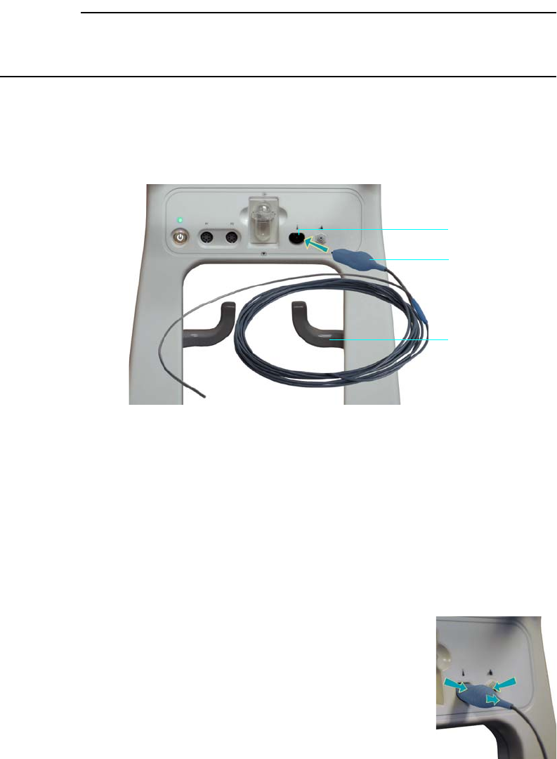
ExpressionMR400InstructionsforUse MonitoringTemperature11‐3
Connecting and Disconnecting the Sensor
CAUTION CAUTION
When inserting or removing the temperature sensor from the MR400, only use the connector and
never pull or apply excessive force or tension to any other portion of the device.
Toconnectthetemperaturesensor
GraspthesensorconnectorthenaligntheconnectortothetemperatureportontheMR400and
pushtheconnectorforwarduntilyoufeelorhearit“click”intoplace.
Tostorethetemperaturesensor
Whennotinuse,looselyloopthesensorandthendrapeitoveranaccessoryhook.
TodisconnectthetemperaturesensorfromtheMR400
Graspthesidesoftheconnector,andthenpulltheconnectoroutofthe
temperatureport.
1Temperature port
2Sensor connector
3Accessory hook
2
1
3
11‐4MonitoringTemperature ExpressionMR400InstructionsforUse
Temperature Measurements
Dependinguponthemonitoringmethod(surfaceorbody),followthecorrespondingprocedure
belowtomakeatemperaturemeasurement.Allowatleast2minutesformeasurement
stabilization,withorwithoutthesensorcover(jacket).
Note
A temperature difference exists between a patient’s surface temperature and body temperature.
Making Surface Temperature Measurements
Whenmakingsurfacetemperaturemeasurements,placethetemperaturesensoratanaxillary
siteaccordingtothestepsbelow.
Tomakesurfacetemperaturemeasurements
Step Action
1 Carefullyuncoilthesensor,usingcaretoavoidknottingorkinking
thedevice.
2Cleananddisinfectthesensor;seeCleaning,Disinfectingand
InspectingtheAccessories,onpage14‐7,fordetails.
3 Thoroughlycleananddrythepatient’saxillaryapplicationsite.
WARNING
Do not place the sensor on or near an open wound.
Failure to comply may result in patient infection.
4 Positionthesensingtipofthesensorattheaxillarysitethenapply
ittothepatient.
5Ifdesired,changetheunitofmeasure(Celsiusisthedefault
setting);seeTEMPMenu,onpage11‐10,fordetails.
6Performthemonitoringprocedure,allowingatleast2minutesfor
themeasurementtostabilize;seeTEMPVSBox,onpage11‐8,for
details.
7 Aftertheprocedure,removethesensorfromthepatient.
8 Immediatelycleananddisinfectthesensor(seePost‐Measurement
Processingonpage11‐7).
ExpressionMR400InstructionsforUse MonitoringTemperature11‐5
Making Body Temperature Measurements
FlexTEMPSystemJacketsaremandatoryforusewiththetemperaturesensorwhenmaking
esophagealorrectal(body)temperaturemeasurements.Beforemakingtemperature
measurementsatesophagealorrectalsites,coverthesensoraccordingtothestepsbelow.
WARNINGS
• Use of FlexTEMP System Jackets are mandatory when using the sensor for body (i.e.,
esophageal or rectal) site temperature measurements. Failure to comply may result in
patient infection.
• Always use a new jacket if a different placement area is desired. Once the sensor has
been used for esophageal or rectal placement, do not change the location unless a new
jacket is installed as patient injury or infection could result.
• Do not reuse a FlexTEMP System Jacket, as they are designed for single-use only.
Failure to comply may result in patient infection.
Placing the Temperature Sensor in a Jacket
FlexTEMPSystemJacketsaresterilepolyurethanesensorcoversandshouldbehandledaccord‐
ingly.Foroptimalstorage,jacketsshouldremainsealedinsterilepacksinclosedcabinetswherea
moderatetemperatureandlowhumidityaremaintained.Whenplacingthesensorinajacket,
ensurethatthesensingtipisfullyinsertedandthatthejackettabsextendoverthepatientseg‐
mentofthetemperaturesensor,asdescribedinthestepsbelow.
Toplacethetemperaturesensorinajacket
Step Action
1 Carefullyuncoilthesensor,usingcaretoavoidknottingorkinking
thedevice.
2Cleananddisinfectthesensor;seeCleaning,Disinfecting,and
InspectingtheAccessories,onpage14‐7,fordetails.
3Opentheindicatedendofajacketpackageenoughtoexposethe
jackettabs.
4Insertthepatientsegmentofthesensorintothejacket.Graspthe
jackettabsthencarefullypullthejacketcompletelyoverthe
patientsegmentofthesensor.
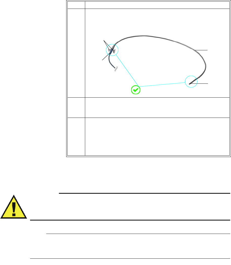
11‐6MonitoringTemperature ExpressionMR400InstructionsforUse
Placing the Temperature Sensor at the Body Site
WARNING
When inserting the sensor into the mouth, use care not to scrape or tear the jacket on the
patient’s teeth and ensure that the patient does not bite the sensor, as this could expose the
sensor and compromise the infection control features of the jacket.
Note
During MRI procedures a large amount of radio frequency (RF) energy is present, which may
cause a patient’s body temperature to increase.
Whenmakingbodytemperaturemeasurements,placethecoveredsensorattheesophagealor
rectalsiteaccordingtothestepsbelow.
5Ensurethatthepatientsegmentofthesensoriscompletely
inserted.Thereshouldbenoexcessspaceatjackettipandthe
jackettabsshouldextendoverthesensor’sjacketretainer.
6Ifneeded,securethejackettabstothejacketretainerusing
medicaltape.Followthestepsbelowtomakeabodytemperature
measurement.
7Whenreadytoapplythesensortothepatient,peelthejacket
packageopenandremovethejacketedsensor,usingcarenotto
soilthesterilizedjacket.
Forsensorplacementinstructions,seePlacingtheSensoratthe
BodySite,below.
Step Action
Jacket
tabs
Jacket
tip
Patient
segment
Jacket
retainer
ExpressionMR400InstructionsforUse MonitoringTemperature11‐7
Tomakebodytemperaturemeasurements
Post-Measurement Processing
Aftermonitoringtemperature,processthesensorasfollows.
Step Action
1Ensurethatajackethasbeenplacedonthesensor(seePlacingthe
SensorinaJacket,onpage11‐5).
2Ifneeded,applylubricanttothejacketforinsertionintothe
patient.
CAUTION CAUTION
Never use petroleum-based lubricants. A water-based lubricant (for
example, Surgical Lubricant, REF 989803168891) can be used to
facilitate insertion.
3Insertthesensingtipofthesensorintothepatientatan
appropriatedepth.
WARNING
Never insert the sensor beyond the patient segment of
the sensor. Insertion beyond the patient segment can
lead to difficulties removing the jacket from the
patient.
4Ifdesired,changetheunitofmeasure(Celsiusisthedefault
setting);seeTEMPMenu,onpage11‐10,fordetails.
5Performthemonitoringprocedure,allowingatleast2minutesfor
themeasurementtostabilize;seeTEMPVSBox,onpage11‐8,for
details.
6 Aftertheprocedure,removethesensorfromthepatient.
WARNING
Ensure that the entire jacket is removed from the
patient when withdrawing the sensor. Failure to do
so can potentially lead to jacket material being left
inside the patient.
7 Immediatelycleananddisinfectthesensor(seePost‐Measurement
Processingonpage11‐7).
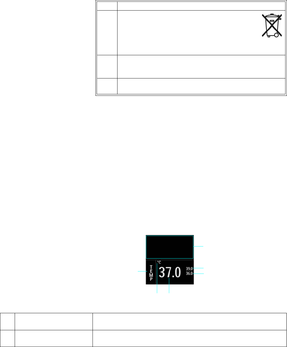
11‐8MonitoringTemperature ExpressionMR400InstructionsforUse
Toprocessthetemperaturesensorafteruse
Accuracy Check
Nocalibrationofthetemperaturesensorisrequired.Iftheaccuracyofameasurementisin
questionorifaproblemissuspectedwiththetemperatureoption,performtheuserroutine‐
tests;seechapter14.
TEMP VS Box
ThetemperaturemeasurementisdisplayedasnumericinformationintheTEMPVSbox.Other
data,includingtemperature‐relatedalarminformation,arealsoprovidedinthisareaofthe
screen,asdetailedbelow.
Step Action
1Ifajacketwasplacedonthesensor,removethejacket
andanymedicaltape(ifused).Refertoyourfacility’s
biohazardprocedurefordisposalofusedjacketsand
medicaltape.Typically,jacketsandtapearedisposed
ofasmedicalwasteperfacilityproceduresdueto
contaminationconcerns.
2 Thoroughlycleananddisinfectthesensor;seeCleaning,
Disinfecting,andInspectingtheAccessories,onpage14‐7,for
details.
3Storethesensor;seeConnectingandDisconnectingtheSensor,on
page11‐3,fordetails.
1
2
3
4
5
6
Item Name Definition
1 Alarm flag area Displays TEMP alarm flags when detected; see page 4-31.
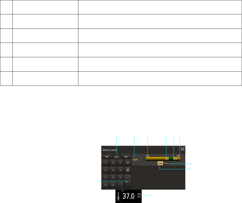
ExpressionMR400InstructionsforUse MonitoringTemperature11‐9
Changing the TEMP Alarm Limits
TheTEMPAlarmLimitsmenucanbeaccessedbytouchingthealarmlimitsettingsintheTEMPVS
box.
2 Temperature upper alarm limit Is the upper limit setting for the TEMP alarm, and accesses the TEMP Alarm
Limits menu
3 Temperature lower alarm limit Is the lower limit setting for the TEMP alarm, and accesses the TEMP Alarm
Limits menu
4 Temperature numeric Is the patient’s detected temperature measurement
5 Unit of measure Indicates that the temperature numeric is given in degrees Celsius (°C) or
degrees Fahrenheit (°F)
6 TEMP VS box label Indicates the temperature vital sign parameter, and accesses the TEMP menu
Item Name Definition
1Alarm limit settings, TEMP VS box
2Enter button
3Current adjustment
4TEMP Alarm Limits menu label
5Alarm limit, minimum
6Lower alarm limit setting
7Upper alarm limit setting
8Alarm limit, maximum
9High button
10 Low button
1
2
346
5
9
10
7 8
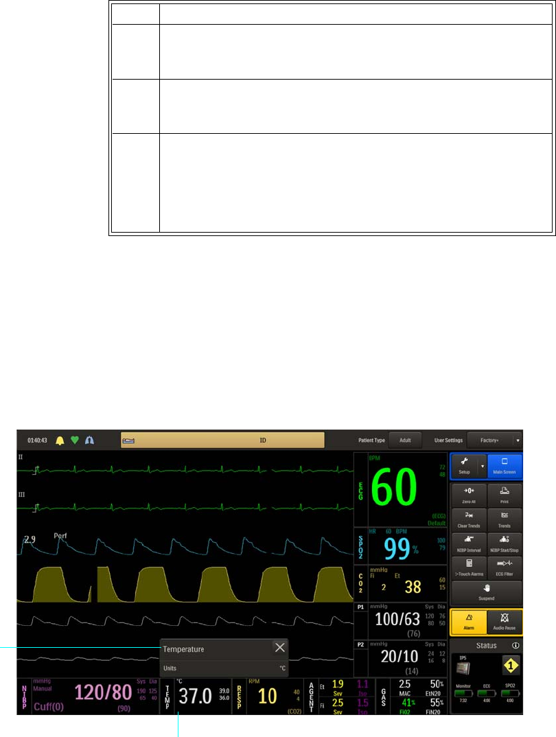
11‐10MonitoringTemperature ExpressionMR400InstructionsforUse
Changing the Unit of Measure
Tochangetheunitofmeasure
TEMP Menu
TheTEMPmenuitemallowsyoutocontroltheunitofmeasurefortemperature.
ToopentheTEMPmenu
SelecttheTEMPVSbox.
Step Action
1 SelecttheTEMPVSbox.
TheTEMPmenuappears.Currentsettingsaredisplayed.
2 SelectUnits.
TheUnitsmenuappears.Thecurrentsettingishighlighted.
3 Selectthedesiredunitofmeasure:
°C
°F
Thesettingischanged.
TEMP VS box
TEMP menu

ExpressionMR400InstructionsforUse MonitoringTemperature11‐11
ThefollowingTEMPmenuitemsareavailable:
Units
Selectstheunitofmeasureusedforpresentationofthetemperaturenumericdata.
Thefollowingoptionsareavailable:
•°C(Default)
•°F
Toselecttheunitofmeasurefortemperature
SeeChangingtheUnitofMeasureonpage11‐10.
1Units
1
11‐12MonitoringTemperature ExpressionMR400InstructionsforUse

ExpressionMR400InstructionsforUseMonitoringNIBP12‐1
CHAPTER 12
Monitoring NIBP
TheNIBP(non‐invasivebloodpressure)parametermeasuresanddisplayssystolic,diastolicand
meanarterialpressures.Alarmlimitsettingsareavailableforallthreepressures.Whenusing
NIBPtomeasurebloodpressure,readingsarenotcontinuousbutareupdatedeachtimeablood
pressuremeasurementistaken.Setashorterintervalwhenfrequentupdatingofthepatient’s
bloodpressureisneeded.Visuallycheckingthepatient,confirmingNIBPmeasurementsagainst
othervitalsignmeasurementsandattentiontothelimbwherethecuffisattachedmustbe
standardroutinesduringNIBPuse.
Adultandpediatricbloodpressuremeasurementsdeterminedwiththisdeviceareequivalentto
thoseobtainedbyatrainedobserverusingthecuff/stethoscopeauscultatorymethod,withinthe
limitsprescribedbytheAmericanNationalStandard,manual,electronic,orautomated
sphygmomanometers.
ThismonitorusestheoscillometricmethodformeasuringNIBP.Studiesshowthat,especiallyin
criticalcases(arrhythmia,vasoconstriction,hypertension,shock),oscillometricdevicesaremore
accurateandconsistentthandevicesusingothernoninvasivemeasuringtechniques.
Inadultandpediatricmode,thebloodpressuremeasurementsdeterminedwiththisdevice
complywiththeAmericanNationalStandardforElectronicorAutomatedSphygmomanometers
(IEC80601‐2‐30:2011)inrelationtomeanerrorandstandarddeviation,whencomparedtointra‐
arterialorauscultatorymeasurements(dependingontheconfiguration)inarepresentative
patientpopulation.Fortheauscultatoryreference,thefifthKorotkoffsoundwasusedto
determinethediastolicpressure.
Inneonatalmode,thebloodpressuremeasurementsdeterminedwiththisdevicecomplywith
theAmericanNationalStandardforElectronicorAutomatedSphygmomanometers(IEC80601‐2‐
30:2011)inrelationtomeanerrorandstandarddeviation,whencomparedtointra‐arterial
measurementsinarepresentativepatientpopulation.Neonatalbloodpressuremeasurements
determinedwiththisdeviceareequivalenttothoseobtainedbyanintra‐arterialbloodpressure
measurementdevice,withinthelimitsprescribedbytheAmericanNationalStandard,manual,
electronic,orautomatedsphygmomanometers.
WARNINGS
• Use clinical judgment to decide whether to perform a repeated series of NIBP
measurements because of the risk of purpura, ischemia and neuropathy in the limb
with the NIBP cuff.
• Arrhythmias, erratic heartbeats and patient motion can result in inaccurate readings
and/or prolonged measurements. If questionable readings are obtained, check the
patient’s vital signs by alternate means before administering medication.
• The performance of the automated sphygmomanometer can be affected by extremes of
temperature, humidity and altitude.
12‐2MonitoringNIBPExpressionMR400InstructionsforUse
CAUTIONS
• Substitution of components or accessories different from those supplied or recommended
can result in measurement errors.
• NIBP accuracy has not been verified in the presence of some common arrhythmias such as
atrial or ventricular premature beats or atrial fibrillation.
Patient Preparation for NIBP Monitoring
WARNINGS
•The NIBP cuff inflation rate may increase and the initial pressure may increase up to
180 mmHg when changing the patient type.
•Patient Category: Select the correct patient category setting for your patient. Do not
apply the higher adult inflation, overpressure limits and measurement duration to
neonatal patients as this may result in inaccurate readings or patient injury.
ThePatientTypeshouldbeselected,asthissettingdeterminestheinflationpressuresofthe
NIBPcuff,readingtimesandappropriatealarmlimitrange.
Whenpositioningthepatient,routineNIBPmeasurements(includingforthecondition
hypertension)requirethepatienttoremainsilent,stillandrelaxed,withlegsuncrossedandarms
supported.NotethatduringMRIprocedures,patientsaretypicallylayingdownwiththeirlegs
uncrossedandarmssupportedasneededfortheMRIscan,anda5‐minutewaitingperiodisalso
recommendedbeforestartingreadings.Ensurethatthecuffisattheleveloftherightatriumof
theheart.
Insomecases,apatientmayexhibitalowpulseamplitudeduetoanyofthefollowing
conditions.Thelistprovidesonlysomeexamplesofpotentialcausesoflowpulseamplitudesthat
canmakeNIBPdifficulttomeasureinaconvenientandtimelymanner:
• Medication
•Sedation
•Diseaseorillness
• Physiologicalorneurologicalconditions
•Obesity(oranyoccurrenceofmetabolismwithextremevariations)
• Stress
•Size

ExpressionMR400InstructionsforUseMonitoringNIBP12‐3
CAUTION
There may be occasions when a particular mode is not suitable for its apparent category of patients
based on age alone. In these cases, a clinical decision shall be made to use another patient type,
NIBP cuff size or measurement technique. The clinical decision shall be based on all of the factors
listed in Determining the Patient Type (see page 3-11) to ensure the best possible and most timely
NIBP measurement acquisition.
Note
Adult and Pediatric types dictate use of a larger NIBP cuff and interconnect hose size, while Neo
uses smaller sizes; see the cuff and hose information on page 1-36.
Selecting the NIBP Cuff
WARNING
To ensure accurate reliable measurements, use only the recommended NIBP accessories. Use
the appropriate NIBP cuff size for each patient, as recommended by the current American
Heart Association guidelines for blood pressure monitoring, to ensure safety and accuracy.
AwidevarietyofNIBPcuffsandinterconnecthosesareavailableforyourmonitoringneeds;see
page1‐36fordetails.
TheNIBPcuffshouldbeselectedasitwouldbeforanauscultatorybloodpressure
determination.ThecurrentguidelinesoftheAmericanHeartAssociationmustbefollowed.
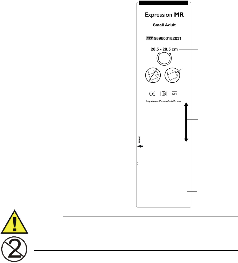
12‐4MonitoringNIBPExpressionMR400InstructionsforUse
Thebladderwidthofthecuffmustbe40
percentofthecircumferenceofthelimb.Itis
alsoadvisabletokeeptheairvolumetoa
minimumbyusingthesmallestcuffsize
possibleforeachpatient.Thepointof
maximumoscillationsiscoincidentwithmean
arterialpressureregardlessofarterialelasticity
solongastheratioofairvolumeinthecuffto
thevolumeofthearteryundercompression
doesnotgreatlyexceedten(10)toone(1).
ForacorrectNIBPcufffit:
•Adultandpediatricpatients—theindex
lineonthesizechosenshouldfallwithin
therangelinewhenplacedonthe
patient.
• Neonatalpatients—thesizechosen
shouldbewithinthestated
circumferencerangeforthelimbofthe
neonate.
•Allpatients—alignthecufftoensurethe
arterymarkisplacedovertheartery.
•Allpatients—themiddleofthecuff
shouldbeplacedattheleveloftheright
atriumoftheheart.
WARNING
Single use devices, as indicated on the device packaging, should be disposed of after use and
must never be reused. Follow your hospital’s guidelines for appropriate disposal. Reuse of
single-use devices can result in spread of patient infection, degradation of monitoring
performance, or inaccurate measurements.
Index line
Range line
Circumference
range
Artery mark
NIBP cuff
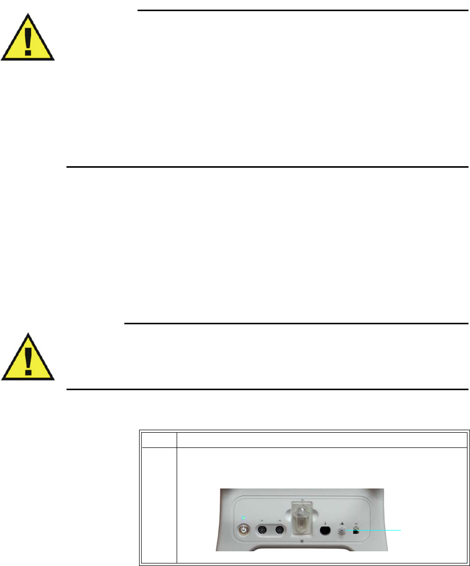
ExpressionMR400InstructionsforUseMonitoringNIBP12‐5
Positioning the NIBPCuff
WARNINGS
•Avoid compression, kinking or restriction of the NIBP cuff hose, as the effect of blood
flow interference can result in patient injury caused by continuous cuff pressure.
• Do not use the NIBP cuff on a limb with an intravenous infusion or where an arterial
catheter or arterio-venous (A-V) shunt is in place because of temporary interference to
blood flow. This could result in injury to the patient.
• Do not place the NIBP cuff over a wound, as this can cause further injury.
• Do not place the NIBP cuff on the same or adjacent arm to a mastectomy, or where the
lymph nodes were removed, or if a shunt is on that arm. This can lead to bruising,
inaccurate readings, or negatively impact the drainage of fluids because of temporary
interference to blood flow.
TheNIBPcuffshouldbepositionedasitwouldbeforanauscultatorybloodpressure
determination.ThecurrentguidelinesoftheAmericanHeartAssociationmustbefollowed.Wrap
theNIBPcufffirmly(notsnuggly)aroundthearmorlegofthepatient,makingsurethatthecuff
isattheapproximatelevelofthehearttoensureaccuracyoftheobtainedvalues.
Connecting the NIBP Cuff
WARNING
Routinely inspect the NIBPcuff and hose assemblies for proper connection and orientation.
Replace accessories that have cracks, holes, tears, or cuts that could cause leaks in the
system. If such damaged NIBP cuff or hose assemblies are used, prolonged and/or inaccurate
patient readings could result.
ToconnecttheNIBPcuffandhose
Step Action
1InserttheappropriateinterconnecthoseconnectorontotheNIBP
port.Pushthehoseconnectorforwardandthenturnitclockwise.
NIBP port

12‐6MonitoringNIBPExpressionMR400InstructionsforUse
Choosing the Measurement Mode
NIBPmeasurementscanbetakenautomaticallyormanually,usingthemodethatbestsuitsthe
needsofyourpatient.ThefollowingarefrequentlyusedfunctionsrelatedtoNIBP;alsoreferto
page12‐14forotherNIBPfunctions.
Making Automatic Measurements
Youcanautomaticallymeasureapatient’sbloodpressureatpredefinedintervals,whichare
measuredfromthestartofoneNIBPmeasurementtothestartofthenext.
Toturnonautomaticoperation
2AttachaNIBPcuffappropriateforthepatienttypeandsizetothe
interconnecthose.
3 Positionthecuffonthepatient;seepage12‐5.
4Ensurethatthecuffandinterconnecthosesarenotkinked.
Step Action
Step Action
1 SelectthePatientType.
SeeSelectingthePatientTypeonpage3‐11.
2PresstheNIBPIntervalkey.
TheIntervalmenuappears.Thecurrentsettingishighlighted.
3 Selectthedesiredminute(s)fortheinterval:
1Min
2Min
3Min
5Min
10Min
15Min
20Min
30Min
Theselectionisentered.
ExpressionMR400InstructionsforUseMonitoringNIBP12‐7
Making Manual Measurements
Youcanmanuallydefinethemeasurementintervalofapatient’sbloodpressure.
Tocontrolmanualoperation
Initial Inflation Pressures and Reading Durations
WARNINGS
• Performing NIBP measurements too frequently can cause injury to the patient due to
blood flow interference.
• Always monitor the NIBP cuff site (for example, by observation of the limb concerned)
to ensure that operation of the automated sphygmometer does not result in prolonged
impairment of the circulation of the blood of the patient.
• Pressurization of the NIBP cuff can temporarily cause loss of function of
simultaneously used monitoring ME equipment on the same limb.
TheinitialinflationpressureistheamountthattheNIBPcuffwillinflateforthefirstNIBP
measurement:
•Adultisusedformostadultpatients:Initialinflationpressure:165±15mmHg
•Pediatricisusedforanypatientexhibitinglowpulseamplitudes(aconditionexhibitedby
pediatric‐sizepatients):Initialinflationpressure:130±15mmHg
•Neoisusedformostneonatalpatients:Initialinflationpressure:100±15mmHg
WhensubsequentNIBPmeasurementsaretakenonthesamepatient(andifnotinsuspend
mode),themonitoradjuststheinflationvalueupordownbasedonthepreviousreadingresults.
4 SelecttheNIBPVSbox.OntheNIBPmenu,toggleAutoModeto
On.
5Tobeginautomaticoperation,presstheNIBPStart/Stopkey.
Step Action
Step Action
1 SelectthePatientType.
SeeSelectingthePatientTypeonpage3‐11.
2Tostartorstopthemeasurement,presstheNIBPStart/Stopkey.
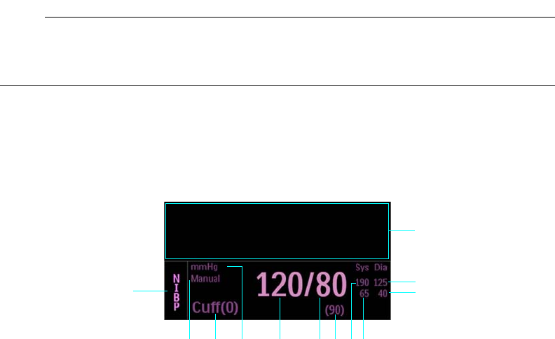
12‐8MonitoringNIBPExpressionMR400InstructionsforUse
Stopping an NIBP Measurement
PresstheNIBPStart/Stopkeytostopareadingcycle.
Suspend Mode during NIBP Measurements
WhentheSuspendkeyispressed,NIBPfunctionswillbeaffectedasfollows:
•Anyreadinginprogresswillbestopped.
•Thesystemwillpumptotheinitialinflationpressurefortheselectedpatienttype.
•Manualreadingscanbetaken.
•Autoreadingscannotbetaken.
•The“NEXT”timerwillnotrun.
•WhenexitingSuspendMode,anymanualreadingwillnotbestopped.
NIBP VS Box
TheNIBPmeasurementsaredisplayedasnumericinformationintheNIBPVSbox.Otherdata,
includingNIBP‐relatedalarminformation,arealsoprovidedinthisareaofthescreen,asdetailed
below.
Note
Depending upon the selected Format (see page 12-17) of the data, the elements contained in the
NIBP VS box are displayed in the Systolic/Diastolic format or in the Mean format.
Systolic/Diastolic Format
1
2
3
4
12
5
67891011

ExpressionMR400InstructionsforUseMonitoringNIBP12‐9
Item Name Definition
1 Alarm flag area Displays NIBP alarm flags when detected; see page 4-31.
2 Dia upper alarm limit Is the upper limit setting for the diastolic alarm, and accesses the NIBP Alarm
Limits menu
3 Dia lower alarm limit Is the lower limit setting for the diastolic alarm, and accesses the NIBP Alarm
Limits menu
4 Sys lower alarm limit Is the lower limit setting for the systolic alarm, and accesses the NIBP Alarm
Limits menu
5 Sys upper alarm limit Is the upper limit setting for the systolic alarm, and accesses the NIBP Alarm
Limits menu
6 Mean numeric Is the patient’s detected mean pressure measurement
7 Diastolic numeric Is the patient’s detected diastolic pressure measurement
8 Systolic numeric Is the patient’s detected systolic pressure measurement
9 Unit of measure Indicates that the NIBP measurement numeric values are given in mmHg
(millimeters of mercury) or kPa (kilopascals)
10 Elapsed time / cuff pressure Is the time since the last completed NIBP reading, in the following format:
<hh>:<mm>:<ss>, where
<hh> = Two-digit hours field
<mm> = Two-digit minutes field
<ss> = Two-digit seconds field
Note
During a reading, this displays the cuff pressure.
11 Auto Mode setting Indicates Manual when in manual mode; or, Next when in automatic mode along
with the time until the next NIBP measurement, displayed in the following
format:
<hh>:<mm>:<ss>, where
<hh> = Two-digit hours field
<mm> = Two-digit minutes field
<ss> = Two-digit seconds field
12 NIBP VS box label Indicates the NIBP vital sign parameter, and accesses the NIBP menu
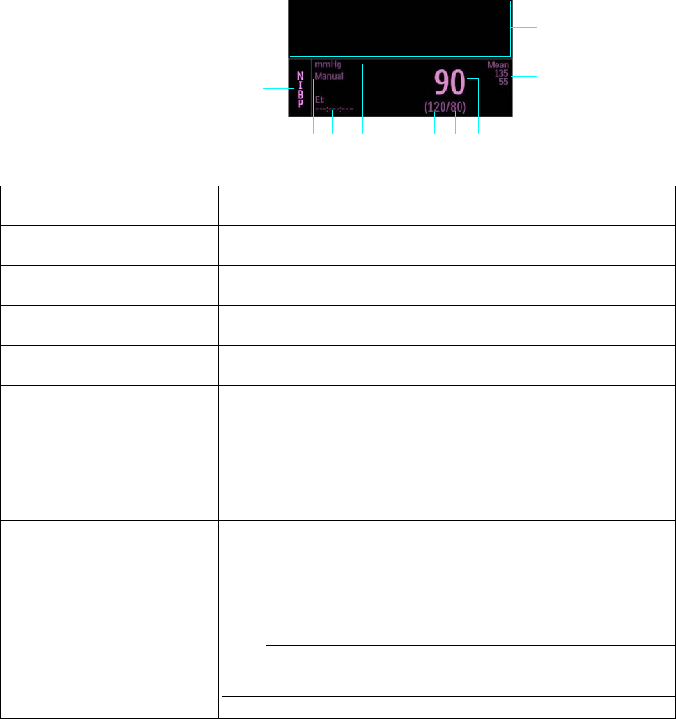
12‐10MonitoringNIBPExpressionMR400InstructionsforUse
Mean Format
1
2
3
4
10
5
6789
Item Name Definition
1 Alarm flag area Displays NIBP alarm flags when detected; see page 4-31.
2 Mean upper alarm limit Is the upper limit setting for the mean alarm, and accesses the NIBP Alarm
Limits menu
3 Mean lower alarm limit Is the lower limit setting for the mean alarm, and accesses the NIBP Alarm
Limits menu
4 Mean numeric Is the detected patient’s mean pressure measurement
5 Diastolic numeric Is the patient’s diastolic pressure measurement
6 Systolic numeric Is the patient’s systolic pressure measurement
7 Unit of measure Indicates that the NIBP measurement numeric values are given in mmHg
(millimeters of mercury) or kPa (kilopascals); see Pressure Units in the
System Config menu on page 3-30.
8 Elapsed time / cuff pressure Is the time since the last completed NIBP reading, in the following format:
<hh>:<mm>:<ss>, where
<hh> = Two-digit hours field
<mm> = Two-digit minutes field
<ss> = Two-digit seconds field
Note
During a reading, this displays the cuff pressure.

ExpressionMR400InstructionsforUseMonitoringNIBP12‐11
Changing the NIBP Format
TocontroltheformatoftheNIBPdata
Changing the Unit of Measure
Note
When using an IP5 and Pressure Units is changed, the displayed formatting of the value and
placement of the decimal point is changed immediately. However, it can take up to 2 seconds for
the measurement numeric values to reflect the new unit of measure. Do not print or perform data
captures during this period.
9Auto Mode setting Indicates Manual when in manual mode; or, Next when in automatic mode along
with the time until the next NIBP measurement, displayed in the following
format:
<hh>:<mm>:<ss>, where
<hh> = Two-digit hours field
<mm> = Two-digit minutes field
<ss> = Two-digit seconds field
10 NIBP VS box label Indicates the NIBP vital sign parameter, and accesses the NIBP menu
Item Name Definition
Step Action
1 SelecttheNIBPVSbox.
TheNIBP1menuappears.Currentsettingsaredisplayed.
2 SelectFormat.
TheFormatmenuappears.Thecurrentsettingishighlighted.
3 Selectthedesiredformat:
SysDia
Mean
Theformatischanged.
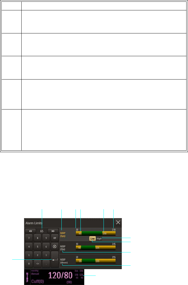
12‐12MonitoringNIBPExpressionMR400InstructionsforUse
Tochangetheunitofmeasure
Changing the NIBP Alarm Limits
TheNIBPAlarmLimitsmenucanbeaccessedbytouchingthealarmlimitsettingsintheNIBPVS
box.
Step Action
1PresstheSetupkeyandthentheMonitorkey.
TheMonitorSetupmenuappears.Currentsettingsaredisplayed.
2OntheMonitorSetupmenu,selectService(Bio‐Med).
TheService(Bio‐Med)menuappears.
3OntheService(Bio‐Med)menu,selectSystemConfig.
TheSystemConfigmenuappears.Currentsettingsaredisplayed.
4OntheSystemConfigmenu,selectPressureUnits.
ThePressureUnitsmenuappears.Thecurrentsettingis
highlighted.
5 Selectthedesiredsetting:
mmHg
kPa
Thesettingisentered.
1Alarm limit settings, NIBP VS box
2Enter button
3Current adjustment
4 NIBP Systolic Alarm Limits menu label (active adjustment shown)
1
2
37
9
45
10
11
12
6 8

ExpressionMR400InstructionsforUseMonitoringNIBP12‐13
TochangetheNIBPalarmlimitsettings
Note
See chapter 4 for detailed alarm limit setting instructions and options.
5Alarm limit, minimum
6Lower alarm limit setting
7Upper alarm limit setting
8Alarm limit, maximum
9High button
10 Low button
11 NIBP Diastolic Alarm Limits menu label
12 NIBP Mean Alarm Limits menu label
Step Action
1 SelectthealarmlimitsettingsintheNIBPVSbox.
TheNIBPAlarmLimitsmenuappears.Currentsettingsare
displayed.
2 Selectthedesiredpressure:
NIBP(Sys)
NIBP(Dia)
NIBP(Mean)
Thepressureisselected.
3 SelecttheLowbuttonortheHighbutton.
Theselectedbuttonwillbehighlightedandthecurrentadjustment
willbedisplayed.
4Usingthekeypad,ortheincrement,decrement,orOffbuttons,
enterthedesiredsetting.
Thecurrentadjustmentwillreflectthechange.
5PresstheEnterbuttontosavethesetting.
Thealarmlimitsettingisupdated.
6
Tochangetheremainingsettings,repeatsteps2,3,4and5.
Thecurrentadjustmentwillreflectthechange.
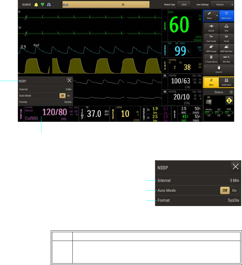
12‐14MonitoringNIBPExpressionMR400InstructionsforUse
NIBP Menu
TheNIBPmenuallowsyoutocontrolnon‐invasivebloodpressurefunctionsandsettings.
ToopentheNIBPmenu
SelecttheNIBPVSbox.
ThefollowingNIBPmenuitemsareavailable:.
TochangesettingsintheNIBPmenu
NIBP menu
NIBP VS box
1Interval
2Auto Mode
4Format
Step Action
1 SelecttheNIBPVSbox.
TheNIBPmenuappears.Currentsettingsaredisplayed.
2
3
1

ExpressionMR400InstructionsforUseMonitoringNIBP12‐15
Interval
SetstheintervalforautomaticNIBPmeasurements.
Thefollowingoptionsareavailable:
•1Min
•2Min
•3Min(Default)
•5Min
•10Min
•15Min
•20Min
•30Min
TosettheintervalforNIBPreadings
2TouchthemenuitemtoselectoneofthefollowingNIBPoptions:
Interval
AutoMode
Format
Themenuitemappears.Thecurrentsettingishighlighted.
3 Selectthedesiredsettingfromthemenuoptions(exceptAuto
Mode,whichisselectableontheNIBPmenu).
Thesettingisentered.
4Tochangeothersettings,repeatsteps2and3.
Step Action
1 SelecttheNIBPVSbox.
TheNIBPmenuappears.Currentsettingsaredisplayed.
Step Action

12‐16MonitoringNIBPExpressionMR400InstructionsforUse
Auto Mode
SetsthemodeusedtotakeNIBPreadings.
Note
A manual reading will not restart this cycle time.
Thefollowingoptionsareavailable:
•Offtakesreadingsmanually(Manualmode),wherereadingsareinitiatedbypressingthe
NIBPStart/Stopkey;seeMakingManualMeasurementsonpage12‐7fordetails.(Default)
•Ontakesreadingsautomatically,wherewhenselected(orsinceleavingsuspendmode),
thefirstreadingmustbeinitiatedbypressingtheNIBPStart/Stopkeyandthenall
subsequentreadingswillbetakenattheselectedinterval;seeMakingAutomatic
Measurementsonpage12‐6forothersetupdetails.
TosetthemodeforNIBPreadings
2 SelectInterval.
TheIntervalmenuappears.Thecurrentsettingishighlighted.
3 Selectthedesiredminute(s)fortheinterval:
1Min
2Min
3Min
5Min
10Min
15Min
20Min
30Min
Thesettingischanged.
Step Action
1 SelecttheNIBPVSbox.
TheNIBPmenuappears.Currentsettingsaredisplayed.
2LocateAutoModeandselectthedesiredsetting:
Off
On
Thesettingisentered.
Step Action
ExpressionMR400InstructionsforUseMonitoringNIBP12‐17
Format
SetsthedisplayedformatoftheNIBPnumericdata.
Thefollowingoptionsareavailable:
•SysDiadisplaysthesystolicanddiastolicnumericsinalargefontseparatedbyaslashand
themeannumericwillbeinasmallerfontbracketedwithparenthesis.(Default)
•Meandisplaysthemeanmeasurementnumericinalargefont,andthesystolicand
diastolicmeasurementnumericvaluesinasmallerfontandseparatedbyaslash.
TocontroltheformatoftheNIBPdata
SeeChangingtheNIBPFormatonpage12‐11.
12‐18MonitoringNIBPExpressionMR400InstructionsforUse

ExpressionMR400InstructionsforUseTrendDataandPrinting13‐1
CHAPTER 13
Trend Data and Printing
Trending Functions
TheMR400providesversatiletrendingfeatures,includingtrendarrowindicationsformonitored
parametersandtabulartrendsreporting.TheMR400storesupto12hoursofhistoricaltrend
data,retaininginformationwhennewpatientsareconnectedtothehostandthroughshort
powercycles;however,ifpowerisremovedfor10minutesorlonger,allstoredtrenddatawillbe
lost.
Viewing Tabular Trend Data
Toviewtabulartrenddataforanyavailableparameter
Tabular Trends Menu
TheTabularTrendsmenuallowsyoutocontroltrendfunctions,todisplaytrendedpatientdata,
andtoprintdatawhenconnectedtoanIP5andprinter.
ToopentheTabularTrendsmenu
PresstheTrendskey.
Step Action
1PresstheTrendskey.
TheTabularTrendsmenuappears.Allowthetrendsdatato
refresh.
2Selectthecorrespondingbutton(s)oftheparameter(s)thatyou
wanttoexamine.
3Usethenavigationbuttons(seepage13‐2)tomovethroughthe
datapages.
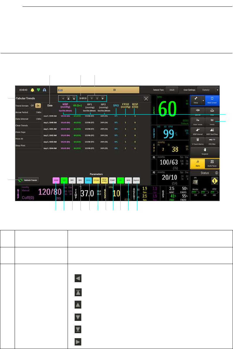
13‐2TrendDataandPrinting ExpressionMR400InstructionsforUse
Notes
•Refreshing Trend Data may be displayed while the information on the page is being
populated.
• In the illustration below, the trend buttons for all parameters are shown in their selected
state.
Item Name Definition
1 Page Indicates the current page and the total page count of the file
2 Navigation buttons Allows you to move through the listings as follows:
Moves one column to the left
Moves to the first (oldest) file page
Moves up one file page
Moves down one file page
Moves to the last (most recent) file page
Moves one column to the right
4
12
567
8
91011
12
13
1415
16
17
18
3

ExpressionMR400InstructionsforUseTrendDataandPrinting13‐3
3 Parameter headings Identifies the parameter reading for the associated column of data
(in the same color as that of the vital sign)
4Trends key Opens the Tabular Trends menu
5Agents trend button Displays the AGENT parameter readings, where percentages for
primary and secondary end-tidal (Et) and fractional inspired (Fi)
gases (ID) are provided in the form: Et ID% Fi ID%
6N2O trend button Displays the N2O parameter readings
7O2 trend button Displays the O2 parameter readings
8TEMP trend button Displays the temperature parameter readings (and the unit of
measure)
9RESP (CO2) trend
button
Displays the CO2-derived respiration parameter readings (and
source)
10 ETCO2 trend
button
Displays the end-tidal CO2 parameter readings (and the unit of
measure)
11 SPO2 trend button Displays the SPO2 parameter readings
12 P2 trend button Displays the P2 parameter readings (and the unit of measure)
13 P1 trend button Displays the P1 parameter readings (and the unit of measure)
14 HR trend button Displays the heart rate parameter readings (and source)
15 NIBP trend button Displays the NIBP parameter readings (and the unit of measure),
given in the form: Systolic/Diastolic (Mean)
16 Refresh Trends
button
Refreshes the readings
Note
While Refreshing Trend Data, the screen will freeze momentarily;
however, audible alarms will continue to function.
17 Tabular Trends
menu
Is the Tabular Trends menu (see below for details)
18 Date Is the date (and time) of the readings
Item Name Definition
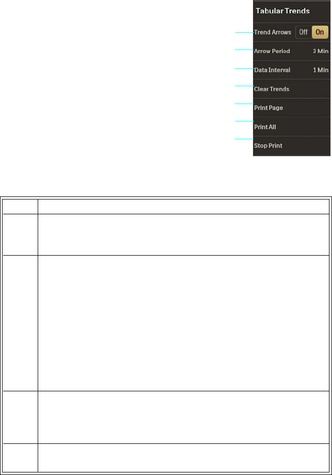
13‐4TrendDataandPrinting ExpressionMR400InstructionsforUse
ThefollowingTabularTrendsmenuitemsareavailable:.
TochangesettingsandcontrolfunctionsintheTabularTrendsmenu
Trend Arrows
Controlsvitalsigntrendindications,wheretrendarrowsaredisplayedalongsidetheVSboxes
(exceptforNIBPandbellows‐derivedrespiration),withameaningasdefinedbelow.
1Trend Arrows
2Arrow Period
3Data Interval
4Clear Trends
5Print Page
6Print All
7Stop Print
Step Action
1PresstheTrendskey.
TheTabularTrendsmenuappears.Currentsettingsaredisplayed.
2 Selectfromthefollowingmenuitems:
TrendArrows
ArrowPeriod
DataInterval
ClearTrends
PrintPage
PrintAll
StopPrint
Formenuiteminformation,seetheappropriatesectionbelow.
3 Selectfromthedesiredsettingofmenuoptions(exceptTrend
Arrows,whichisselectableontheTabularTrendsmenu.)
Thesettingisentered.
4Tochangeothersettings,repeatsteps2and3.
2
3
4
1
5
6
7
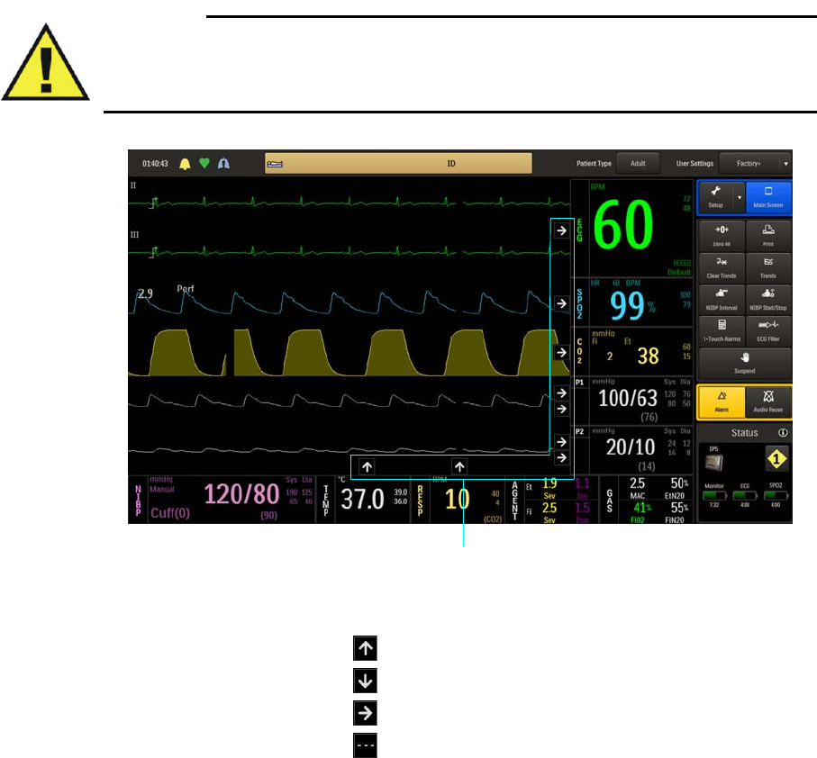
ExpressionMR400InstructionsforUseTrendDataandPrinting13‐5
WARNING
Depending upon the Arrow Period menu option and measurement cycles of the vital signs,
NIBP trend arrow indications may not be representative of the current condition of the
patient.
Thefollowingoptionsareavailable:
•Offturnsoffthetrendarrows.(Default)
•Onturnsonthetrendarrows.
1Trend arrow indications, where
is rising
is declining
is stable
is none declared
1

13‐6TrendDataandPrinting ExpressionMR400InstructionsforUse
Tocontroltrendarrowindications
Arrow Period
Controlsthetimethatmustelapsebeforeatrendarrowchangecanoccur.
Thefollowingoptionsareavailable:
•30Seconds
•1Minute
•3Minutes(Default)
•5Minutes
•10Minutes
Tocontrolthetrendarrowperiod
Step Action
1PresstheTrendskey.
TheTabularTrendsmenuappears.Currentsettingsaredisplayed.
2OntheTabularTrendsmenu,selectTrendArrows.
TheTrendArrowsmenuappears.Thecurrentsettingishighlighted.
3 Selectthedesiredsetting:
Off
On
Thesettingischanged,andthedisplayischangedaccordingly.
Step Action
1PresstheTrendskey.
TheTabularTrendsmenuappears.Currentsettingsaredisplayed.
2OntheTabularTrendsmenu,selectArrowPeriod.
TheArrowPeriodmenuappears.Thecurrentsettingishighlighted.

ExpressionMR400InstructionsforUseTrendDataandPrinting13‐7
Data Interval
Controlsthetimethatmustelapsebeforetrenddatareadingsaretaken.
Thefollowingoptionsareavailable:
•1Minute
•5Minutes(Default)
•10Minutes
•15Minutes
•20Minutes
•25Minutes
•30Minutes
•45Minutes
•60Minutes
•AutoNIBP(OccursattheIntervalselectedforautomaticNIBPmeasurements;seepage
12‐15fordetails)
3 Selectthedesiredsetting:
30Seconds
1Minute
3Minutes
5Minutes
10Minutes
Thesettingischanged.
Note
If a newly selected period is shorter than the previous period (and
the arrows have been on for the longer of the two periods) then
immediate recalculation using the new period will occur. However, if
the newly selected period is longer than the previous period,
recalculation will occur using all available data.
Step Action

13‐8TrendDataandPrinting ExpressionMR400InstructionsforUse
Tocontrolthedatainterval
Clear Trends
Removesalltrenddata,usefultoensurethatthemonitoredinformationreflectsdataforonlyone
patient.
Toclearalltrenddata
Step Action
1PresstheTrendskey.
TheTabularTrendsmenuappears.Currentsettingsaredisplayed.
2OntheTabularTrendsmenu,selectDataInterval.
TheDataIntervalmenuappears.Thecurrentsettingishighlighted.
3 Selectthedesiredsetting:
1Minute
5Minutes
10Minutes
15Minutes
20Minutes
25Minutes
30Minutes
45Minutes
60Minutes
AutoNIBP
Thesettingischanged.
Step Action
1PresstheClearTrendskey.
TheTabularTrendsmenuappears.Currentsettingsaredisplayed.
2OntheTabularTrendsmenu,selectClearTrends.
TheClearTrendsmenuappears.
3 Followallassociateddialogstoclearthefile.Thedataiserased.

ExpressionMR400InstructionsforUseTrendDataandPrinting13‐9
Print Page
PrintsthecurrentlydisplayedTrendspagewhenconnectedtoaprinter‐equippedIP5.
Toprintthepage
Print All
PrintsallTrendspageswhenconnectedtoaprinter‐equippedIP5.
Toprinttheallpages
Stop Print
Stopsprintingofthetrendspage(s)whenconnectedtoaprinter‐equippedIP5.
Tostopacurrentprintjob
Step Action
1PresstheTrendskey.
TheTabularTrendsmenuappears.Currentsettingsaredisplayed.
2OntheTabularTrendsmenu,selectPrintPage.
Step Action
1PresstheTrendskey.
TheTabularTrendsmenuappears.Currentsettingsaredisplayed.
2OntheTabularTrendsmenu,selectPrintAll.
Step Action
1PresstheTrendskey.
TheTabularTrendsmenuappears.Currentsettingsaredisplayed.
2OntheTabularTrendsmenu,selectStopPrint.

13‐10TrendDataandPrinting ExpressionMR400InstructionsforUse
Printing Functions
WhenequippedwithanIP5andprinter,theMR400canproducehardcopiesofuptotwo
waveforms,trendinformationandpatientdatareports.
Notes
• If a printer-equipped IP5 is not installed or connected, an indication is displayed on the
Print key; see page 13-11.
• Any print command from the MR400 automatically initiates a 30-second print cycle at the
IP5.
• Any print command initiated from the MR400 takes precedence over the IP5 print functions.
Printing Parameter-Specific Trends
Trendedinformationcanbeprintedseparatelyforeveryparameter(exceptbellows‐derived
respiration).
Toprintindividualtrenddata
Controlling Printer Outputs
Tostartandstoptheprintingofastripchart,pressthePrintkey.
Iftheprinterisallowedtorunafterprinting,paperwillcontinuetobeoutputforabout30
secondsbeforeautomaticallystopping.
Step Action
1PresstheTrendskey.
TheTabularTrendsmenuappears.Allowthetrendsdatato
refresh.
2 Selectthetrendbuttonoftheparameterthatyouwanttoprint.
Thecorrespondingvitalsigndataappears.Thecurrentpageis
displayed.
3 SelectPrintAlltoprintallthedatafortheparameter,orselect
PrintPagetoprintthecurrentlydisplayeddata.
ThedataisprintedattheIP5.
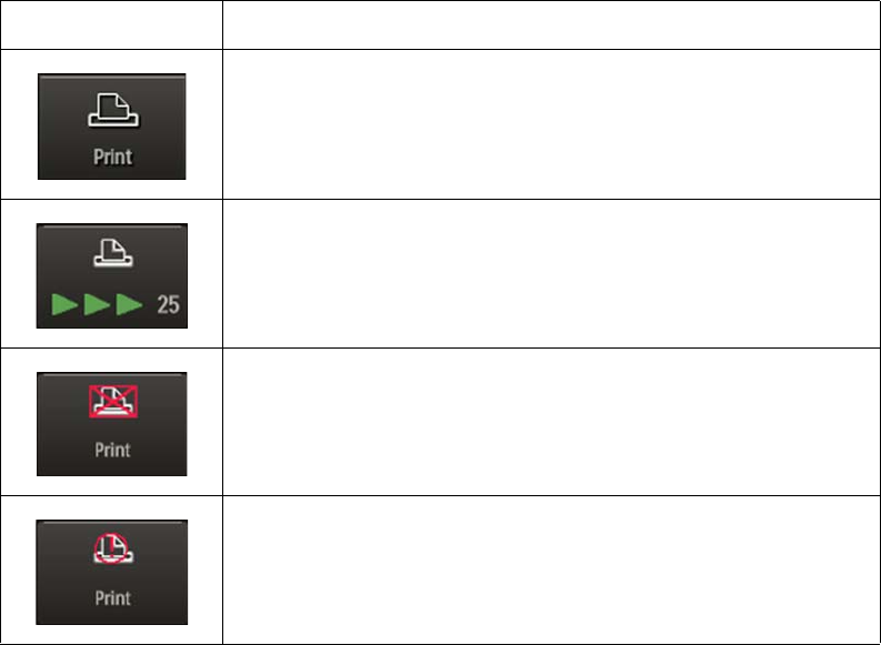
ExpressionMR400InstructionsforUseTrendDataandPrinting13‐11
Printer Indications
ThesymboldisplayedonthePrintkeyindicatesthestateoftheremoteprinter,asshowninthe
tablebelow.
Printer Menu
ThePrintermenuallowsyoutoconfiguretheMR400forprintingwhenanoptionalIP5and
printerareconnected.
ToopenthePrintermenu
PresstheSetupkeyandthenthePrinterkey.
ToopenthePrintermenu
PresstheSetupkeyandthenthePrinterkey.
Symbol Indication
Theprinterisready.
Printingisinprocessandsecondsremain(25,intheexample)until
completion.
Noprinterisavailable.
Thereisaprintererrorcondition.
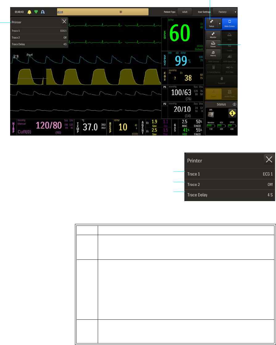
13‐12TrendDataandPrinting ExpressionMR400InstructionsforUse
.
ThefollowingPrintermenuitemsareavailable:
TochangesettingsinthePrintermenu
Setup key
Printer key
Printer
menu
1Trace 1
2Trace 2
3Trace Delay
Step Action
1PresstheSetupkeyandthenthePrinterkey.
ThePrintermenuappears.Currentsettingsaredisplayed.
2 Selectfromthefollowingmenuitems:
Trace1
Trace2
TraceDelay
Theselectedmenuappears.Currentsettingsaredisplayed.(For
menuiteminformation,seetheappropriatesectionbelow.)
3 Selectthedesiredmenuitem.
Thecurrentsettingishighlighted.
2
3
1
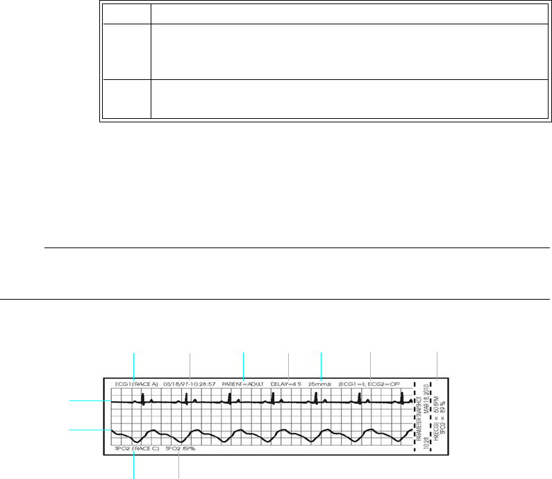
ExpressionMR400InstructionsforUseTrendDataandPrinting13‐13
Trace 1
Printsaselectedparameter’swaveformintheTrace1waveformlocationonastripchart,as
shownintheillustrationbelow.(Astripcancontaintwowaveforms.)
Note
If Trace 2 is off, then Trace 1 is printed using the full 40 mm width of the strip.
Thefollowingoptionsareavailable:
•ECG1outputstheTraceAwaveform(Default)
4 Selectthedesiredsettingfromthemenuoptions.
Thesettingisentered.
5Tochangeothersettings,repeatsteps2,3and4.
1Trace 1 setting
2Date and time (formatted as MM/DD/YY-HH:MM:SS)
3Patient type
4Trace delay
5Trace speed
6Parameter setting information
7Values of active parameters at time of printing
8Trace 2 parameter information
9Trace 2 setting
10 Trace 2 waveform
11 Trace 1 waveform
Step Action
1234567
8
9
11
10

13‐14TrendDataandPrinting ExpressionMR400InstructionsforUse
•ECG2outputstheTraceBwaveform
•SPO2outputstheTraceCwaveform
•RESP(CO2)outputstheTraceDwaveform
•P1outputstheTraceEwaveform
•P2outputstheTraceFwaveform
ToprintawaveformintheTrace1location
Trace 2
PrintsawaveformintheTrace2locationonastripchart(seeexample,onpage13‐13).
Note
When printing two traces, the waveform to grid ratio will not correspond to the displayed
waveform/scale indicator size.
Thefollowingoptionsareavailable:
•Off(Default)
•ECG1outputstheTraceAwaveform.
•ECG2outputstheTraceBwaveform.
•SPO2outputstheTraceCwaveform.
•P1outputstheTraceEwaveform.
Step Action
1PresstheSetupkeyandthenthePrinterkey.
ThePrintermenuappears.Currentsettingsaredisplayed.
2 SelectTrace1.
TheTrace1menuappears.Thecurrentsettingisdisplayed.
3 Selectthedesiredsettingfromthemenuoptions:
ECG1
ECG2
SPO2
RESP(CO2)
P1
P2
Thesettingisentered.

ExpressionMR400InstructionsforUseTrendDataandPrinting13‐15
•P2outputstheTraceFwaveform.
•RESP(CO2)outputstheTraceDwaveform.
ToprintawaveformintheTrace2location
Trace Delay
Allowsyoutodelaythetimewhensendingthetracedatatotheprinter.
Thefollowingoptions(inseconds)areavailable:
•0S
•4S(Default)
•8S
•16S
Tosetaprintingtimedelay
Step Action
1PresstheSetupkeyandthenthePrinterkey.
ThePrintermenuappears.Currentsettingsaredisplayed.
2 SelectTrace2.
TheTrace2menuappears.Thecurrentsettingisdisplayed.
3 Selectthedesiredsettingfromthemenuoptions:
Off
ECG1
ECG2
SPO2
P1
P2
RESP(CO2)
Thesettingisentered.
Step Action
1PresstheSetupkeyandthenthePrinterkey.
ThePrintermenuappears.Currentsettingsaredisplayed.
2 SelectTraceDelay.
TheTraceDelaymenuappears.Thecurrentsettingisdisplayed.

13‐16TrendDataandPrinting ExpressionMR400InstructionsforUse
3 Selectthedesiredsettingfromthemenuoptions:
0S
4S
8S
16S
Thesettingisentered.
Step Action

ExpressionMR400InstructionsforUseMaintenanceandTroubleshooting14‐1
CHAPTER 14
Maintenance and Troubleshooting
WARNINGS
• Schedule: Failure on the part of the responsible individual hospital or institution
employing the use of this equipment to implement a satisfactory maintenance schedule
may cause undue equipment failure and possible health hazards.
• To reduce the possibility of damage to the equipment or injury to patients/personnel,
perform all cleaning, disinfection, maintenance, software update, testing, disassembly
and repair outside of the MR system room.
• Contact: If you discover a problem with any of the equipment, contact technical
support or authorized service personnel.
General Cleaning Guidelines
KeeptheMR400andaccessoriesfreeofdust,dirtandpathogens.Aftercleaninganddisinfection,
alwayschecktheequipmentcarefully.Stopusingequipmentthatshowssignsofdeteriorationor
damage.Observethefollowinggeneralprecautionswhencleaning:
•Alwaysdilutethecleaningsubstanceaccordingtothemanufacturer’sinstructionsoruse
lowestpossibleconcentration.
• Neverallowliquidtoentertheequipment.
• Neverimmerseanypartoftheequipmentinliquid.
• Neverpourliquidontotheequipment.
• Neveruseabrasivematerialtowipetheequipment.
Note
For answers to questions regarding infection control, call us at (877) 468-4861 (inside the USA) or
+31 (0) 499 378299 (outside the USA).
Cleanusingalint‐freecloth,moistenedwithwarmwater(40°C/104°Fmaximum)andmildsoap,
adilutednon‐causticdetergentoralcohol‐basedcleaningagent.Neverusestrongsolventssuch
asacetoneortrichloroethylene.Stainscanberemovedbyscrubbingbrisklywithamoistened
cloth.Ifdisinfectionisrequired,cleantheequipmentbeforedisinfectingit.
Whencleaningthetouchscreen,wipeitgentlyusingasoftnon‐wovenclothwith80%diluted
alcoholmixture.

14‐2MaintenanceandTroubleshooting ExpressionMR400InstructionsforUse
UseonlytheRoyalPhilips‐approvedsubstancesandmethodslistedinthischaptertocleanor
disinfecttheequipment.RoyalPhilipsmakesnoclaimsregardingtheefficacyofthelisted
chemicalsormethodsasameansforcontrollinginfection.Warrantydoesnotcoverdamage
causedbyusingunapprovedsubstancesormethods.
Therecommendedtypesofdisinfectingagentsarelistedinthetablebelow.Wemakenoclaims
regardingtheefficacyofthelistedchemicalsormethodsasameansforcontrollinginfection.
Consultyourfacility'sInfectionControlOfficerorEpidemiologist.Forcomprehensivedetailson
cleaningagentsandtheirefficacyrefertoGuidelinesforPreventionofTransmissionofHuman
ImmunodeficiencyVirusandHepatitisBVirustoHealthCareandPublic‐SafetyWorkersissuedby
theU.S.DepartmentofHealthandHumanServices,PublicHealthService,CentersforDisease
Control,February1989.Alsorefertoanypoliciesthatapplywithinyourfacilityandcountry.
*Anyproductresidueshouldberemovedbywipingthesurface.
Removing all Power to the MR400
Inordertoclean,disinfect,inspect,testorservicetheMR400,itmaybenecessarytoremove
powertothecart.
ToremoveallpowertotheMR400cart
Product Name Product Type
Cavicide Disinfectant: CaviWipes® Towelette
Coverage Disinfectant: Coverage® Spray TB, TB Plus, HB Plus* Spray
Sani-Cloth Germicidal Wipes* Towelette
Sklar Disinfectant* Towelette, spray
Step Action
1Pressthenholdthepowerswitchforapproximately2secondsto
turnoffpowertothecart.
2PulltheplugofpowercordfromtheACwalloutlet.Then,liftthe
strainreliefandremovethepowercordfromtheACreceptacleon
thecart.Disconnectanygatingconnectionfromthecart;
otherwise,removetheshieldcap.
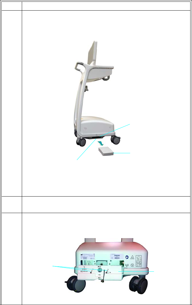
ExpressionMR400InstructionsforUseMaintenanceandTroubleshooting14‐3
3Pressthebatteryejectbuttontopartiallyejectamaincartbattery
fromabatterycompartment,andthengraspthebatteryandpull
toremoveitcompletelyfromtheMR400.
(Ifthebatterydoesnotrelease,applyaslightforwardpressureto
thebatterywhilepressingthebatteryejectbutton.)
4Repeatsteps1and2toremovetheothermaincartbatteryonthe
oppositesideoftheMR400.
5 Removethetwoscrewsthatsecuretheservicepanelcovertothe
MR400andthenremovetheservicepanelcover.
Step Action
Main cart battery
Battery compartment
Battery eject button
Screws Service panel
cover
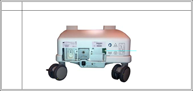
14‐4MaintenanceandTroubleshooting ExpressionMR400InstructionsforUse
Restoring all Power to the MR400
TorestoreallpowertotheMR400,seepage1‐16.
Removing Power from the Wireless Modules
Inordertoclean,disinfectorinspectawirelessmoduleitmaybenecessarytoremovepower
fromthedevice.Toturnpowerofftothewirelessmodules,proceedaccordingtothemodule
type:
•wECGmodule:Removeallinstalledbatteries(seepage1‐25).
•wSpO2module:Removethebattery(seepage1‐27).
Restoring Power to the Wireless Modules
Torestoreallpowertothewirelessmodules,proceedaccordingtothemoduletype:
•wECGmodule:Installatleastonebattery(seepage1‐24).
•wSpO2module:Installonebattery(seepage1‐26).
User Routine-Checks and Planned Maintenance
Thisproductrequiresroutinechecking,plannedmaintenanceandtestingthatmustperformed
onascheduledbasistokeeptheproductoperatingsafely,effectivelyandreliably.
UserRoutine‐ChecksProgram
6LocatethebatteryswitchandtoggleitintotheOff(O)position.
Step Action
Battery switch

ExpressionMR400InstructionsforUseMaintenanceandTroubleshooting14‐5
Theuseroftheproductmustinstitutearoutine‐checksprogramasdetailedinthetablebelow.
Theuseroftheproductshallmakesurethatallchecksandactionshavebeensatisfactorily
completedbeforeusingtheproductforitsintendedpurpose.
PlannedTestingProgram
Plannedmaintenancemayonlybecarriedoutbyqualifiedandauthorizedpersonnel,andis
comprehensivelydescribedintheservicedocumentation.Philipsprovidesafullplanned
maintenanceandrepairserviceonbothacallbasisandacontractbasis.Fulldetailsareavailable
fromyourPhilipsServiceOrganization.Asummaryofserviceeventsandmaintenance
requirementsappearsinthetablebelow.
Area / Item Frequency Required Action
Accessories Daily Clean and inspect for damage; see page 14-7.
Alarms Daily Confirm proper function; see Testing Alarms on page
14-11.
Module batteries Every 8 hours
of use
Recharge; see page 2-16 for displayed indications, and
refer to the battery charger’s IFU for recharging
instructions.
Wireless module If dropped Inspect and clean (see page 14-9) then test (see page
14-12).
Area / Item Frequency Required Action
Monitor cleaning Every 6 months Perform external cleaning
System -
AGENT option
Once per year
or as specified
by local laws
Perform calibration.
System - CO2
(LoFlo option)
Once per year
or as specified
by local laws
Perform calibration.
System- NIBP Once per year
or as specified
by local laws
Perform calibration.
System Once per year
or as specified
by local laws,
or after any
type of repair
or service
event
Perform Visual Inspection, and Power On, Verification
and Safety Tests

14‐6MaintenanceandTroubleshooting ExpressionMR400InstructionsforUse
Cleaning, Disinfection, and Damage Inspection
Cleaninganddisinfectionofthisproductisrequiredperiodically.Generalguidelinesforeachare
givenbelow.
WARNING
Always isolate the product from the mains electrical supply and remove and disconnect
batteries before cleaning, disinfecting or sterilizing to prevent electric shocks.
CAUTION
Never allow water or other liquids to enter the product, since these may cause electrical short-
circuits or metal corrosion.
Cleaninganddisinfectiontechniquesforboththeproductandtheroommustcomplywithall
applicablelocallawsandregulations.
Cleaning
Enameledpartsandaluminumsurfacesshouldonlybewipedcleanwithadampclothandamild
detergent,andthenrubbeddownwithadrywoolencloth.Neverusecorrosivecleaningagents,
solvents,abrasivedetergentsorabrasivepolishes.Ifyouarenotsureaboutthepropertiesofa
cleaningagent,donotuseit.
Disinfection
Thosepartsoftheproductthataresuitableforsuchtreatment,includingaccessoriesand
connectingcables,canbedisinfectedbygentlywipingthesurfaceswithaclothdampenedwitha
suitableagentforabriefperiod(30secondsto1minute)orasdirectedbythesubstance
manufacturer.Neverusecorrosiveorsolventdisinfectantsorsterilizingagents.Ifyouarenot
sureaboutthepropertiesofadisinfectantorsterilizingagent,donotuseit.
Cart batteries:
two main and
two reserve
Every 12
months
• Replace the main batteries; see page 1-16.
• Replace the reserve batteries; contact technical
support.
Module
batteries
Every 12
months
Replace the module batteries; see page 1-23.
Area / Item Frequency Required Action
ExpressionMR400InstructionsforUseMaintenanceandTroubleshooting14‐7
WARNING
Do not use flammable or potentially explosive disinfecting sprays. Such sprays create vapors,
which can ignite, causing fatal or other serious personal injury.
CAUTION
Disinfecting a medical product room by means of sprays is not recommended, since the vapor
could penetrate the product, causing electrical short-circuits, metal corrosion or other damage to
the product.
Cleaning, Disinfecting, and Inspecting the Accessories
Anyreusablepatientaccessory(suchasECGcables,SPO2attachmentsandprobes,temperature
sensors,etcetera)mustbecleanedanddisinfectedbeforeinitialuseandaftereachuseto
protectpatientsandpersonnelfromavarietyofpathogens.Usesoapandwater,andasuggested
disinfectantandmethod,tocleananddisinfecttheaccessories.Thewarrantydoesnotcover
damagecausedbyunapprovedsubstancesormethods.
Duringthecleaningprocess,inspecttheaccessoryfordamage.Theaccessoriesareexposedto
potentiallydamagingsituationsduringuseandcleaning.Beforeeachuse,carefullyinspectthe
accessoriesforthefollowingsignsofdamage:
•Cracks,holes,tears,gouges,cuts,etcetera.
•Cracksorothersignsofdamagetotheconnector,includingbentordamagedpins.
• Disposableaccessoriesmustbediscardedandreplacedwithnewitems.
WARNING
Cracks, tears, cuts and gouges interfere with standard cleaning procedures and therefore
pose a potential risk to patients and personnel. If you see any sign of damage to any
accessory, immediately discontinue use.
WARNING
Single-use devices, as indicated on the device packaging, should be disposed of after use and
must never be reused.Reuse of single-use devices can result in spread of patient infection,
degradation of monitoring performance, or inaccurate measurements.
CAUTIONS
• Never immerse an accessory in any cleaning fluid.
• Do not autoclave any part of the equipment. Disinfect the accessory as determined by your
facility’s policy.

14‐8MaintenanceandTroubleshooting ExpressionMR400InstructionsforUse
Tocleanareusableaccessory
Step Action
1 Removetheaccessoryfromuse.
2 Removeallvisibledebrisfromtheaccessoryusingsoapandwater.
CAUTION
Never pour liquid onto the accessory.
3CleantheaccessorybythoroughlywipingitusingCaviWipes
disinfectanttowelettes.Discardtheusedtowelettes(refertoyour
facility'sbiohazardprocedurefordisposal).
Note
Follow the Instructions for Use from the disinfectant manufacturer
to clean the probe.
4DisinfecttheaccessorybythoroughlywettingitusingCaviWipes
disinfectanttowelettes.Discardtheusedtowelettes(refertoyour
facility'sbiohazardprocedurefordisposal).
Note
Follow the Instructions for Use from the disinfectant manufacturer
to disinfect the probe.
5Allowtheaccessorytodry.(Norinsingisrequired.)
6
Checktheaccessoryforanyresidualdebris.Ifanydebrisispresent,
repeatsteps2through5thenre‐examinetheitembefore
proceeding.
Note
Disposable SPO2 attachments: After some use, adhesive residue may
accumulate at the fiber heads on the probe. Carefully remove any
residue with alcohol to keep the glass fiber ends clean.
7Checktheaccessoryfordamage(cracks,holes,tears,cuts,et
cetera)anddiscardtheaccessoryifdamageisfound.
8Storetheaccessory;seepage2‐12fordetails.
ExpressionMR400InstructionsforUseMaintenanceandTroubleshooting14‐9
Cleaning, Disinfecting, and Inspecting MR400 and Wireless Modules
FollowthegeneralguidelinestocleantheMR400cartandthewECGandwSpO2modules.
Alwaysturnoffthecartandthewirelessmodulestoperformcleaning.Neverimmerseany
portionofthecartorwirelessmodulesinfluidorattempttocleanthedevicesbydirectly
applyingliquidcleaningagents.
Duringthecleaningprocess,inspecttheMR400andthewirelessmodulesfordamaged,looseor
missinghardware;iffound,takecorrectiveactionorcontacttechnicalsupport.
WARNING
Always disconnect the MR400 from AC mains power, and remove the batteries from the
cart and the wireless modules, before performing any cleaning or maintenance. To avoid an
electrical hazard, never immerse any part of the MR400 in any cleaning agent or attempt to
clean it with liquid cleaning agents.
CAUTIONS
• Other than those specified in the preceding table, avoid ammonia-, phenol- and acetone-
based cleaners as they will damage the surfaces of the MR400.
• Disinfect the MR400 cart and wireless modules as determined by your hospital’s policy to
avoid long term damage to the product.
• Do not permit liquid to contact the front or rear of the display panel. Do not permit liquid to
drip into or around the touch screen. Contact technical support if liquid enters any
component.
• If the MR400 becomes accidentally wet during use, discontinue operation until all affected
components have been cleaned and permitted to completely dry. Contact technical support if
additional information is required.
Tocleananddisinfectthecartandwirelessmodules
Step Action
1TurnofftheMR400anddisconnectallpower;seepage14‐2.
2 Removethebatteryfromeachwirelessmodule;seepage14‐4.
3Cleanthetouchscreenbywipingitgentlyusingasoftnon‐woven
clothwith80%dilutedalcoholmixture.
4 Removeallvisibledebrisfromthecartandwirelessmodulesusing
soapandwater.
CAUTIONS
Never pour liquid onto the equipment.

14‐10MaintenanceandTroubleshooting ExpressionMR400InstructionsforUse
Sterilization
TheMR400cart,wirelessmodulesandaccessoriesarenotsterilizable;donotimmerseanypartof
theseitemsinfluidorattempttocleanthemwithunspecifiedliquidcleaningagents.Severe
damage,notcoveredbythewarranty,willresult.
5Cleanthecartandmodulesbythoroughlywipingthedevicesusing
CaviWipesdisinfectanttowelettes.Discardtheusedtowelettes
(refertoyourfacility'sbiohazardprocedurefordisposal).
Note
Follow the Instructions for Use from the disinfectant manufacturer
to clean the cart and wireless modules.
6Disinfectthecartandmodulesbythoroughlywettingthedevices
usingCaviWipesdisinfectanttowelettes.Discardtheused
towelettes(refertoyourfacility'sbiohazardprocedurefor
disposal).
Note
Follow the Instructions for Use from the disinfectant manufacturer
to disinfect the cart and wireless modules.
7Allowthecartandthewirelessmodulestodry.(Norinsingis
required.)
8Checkthecartandthewirelessmodulesforanyresidualdebris.If
anydebrisispresent,repeatsteps3through6thenre‐examinethe
cartandwirelessmodulesbeforeproceeding.
9Checkthecartandwirelessmodulesfordamaged,looseormissing
hardware.Contacttechnicalsupportifnecessary.
10 Storethemodule;seepage2‐12fordetails.
Step Action

ExpressionMR400InstructionsforUseMaintenanceandTroubleshooting14‐11
Testing Alarms
Note
If a problem with the alarm sound or messaging system is suspected, discontinue use of the
MR400 and immediately refer it to authorized service personnel for evaluation.
Toverifythealarmfunctions
Step Action
1WiththeMR400turnedonandnotinsuspendmode,ensurethat
AlarmSoundisturnedonintheAlarmsmenu.
2MakesurethattheloweralarmlimitforSPO2isnotoff.
3CheckthebatteryindicatoronthewSpO2moduletoensurethat
enoughchargeexists:
• Greenbatteryindicator=Chargesufficient;proceedtostep5.
•Redbatteryindicator=Chargelow;proceedtostep4.
Seepage2‐11fordetails.(Also,youcanreferencethestatus
informationpane;seepage2‐16.)
4InsertachargedmodulebatteryintothewSpO2moduleandthen
recheckthebatteryindicatortoensureasufficientchargebefore
proceeding;seepage1‐26.
5CheckthenetworkchannelindicatoronthewSpO2moduleto
ensurecommunicationisestablishedwiththeMR400:
• Steady=Goodcommunication;proceedtostep7.
• Flashing=Nocommunication;proceedtostep6.
Seepage2‐11fordetails.(Also,youcanreferencethestatus
informationpane;seepage2‐16.)
6EnsurethatthewSpO2moduleiswithin9.1m(30feet)ofthe
MR400,inthesameMRIroomorinthesameshieldedroom,andis
settothesamewirelessnetworkchannelusedbytheMR400;see
page1‐29.
7PlacetheSPO2attachmentonyourfingerandwaitforavalueto
appearintheSPO2VSbox.

14‐12MaintenanceandTroubleshooting ExpressionMR400InstructionsforUse
Testing a Dropped Wireless Module
IntheeventthatthewECGorwSpO2modulehasbeendropped,itisimportanttodeterminethe
functionalityofthedevicebeforeattemptingtomonitorapatient.
Toverifythebasicfunctionsofadroppedwirelessmodule
8 Removeyourfingerfromtheattachment.
9Verifythefollowing:
•Non‐PulsatorProbeOffappearsintheSPO2alarmflagarea,
•TheSPO2waveformflatlines.
•Thenumericflashesinyellow;and,
•Thealarmtonesounds.
Thiscompletesthetestofthealarmsystem.
Step Action
Step Action
1Performavisualexaminationthedroppedmoduleforsignsof
breakage(crackedhousings,damagedconnectors,etcetera):
•Ifnosignsofdamagearepresent,gotostep2;or,
•Ifnoticeabledamageispresent,gotostep6.
2Ensurethatafreshmodulebatteryisinstalled.(Ifcheckingthe
wECGmodule,ensurethattwofreshbatteriesareinstalled.)Then,
checkthemoduleandproceedaccordingly:
•Ifthebatteryindicator(s)andnetworkchannelindicatorare
illuminated,gotostep3;or,
•Ifthebatteryindicator(s)andnetworkchannelindicatorare
NOTilluminated,gotostep6.
3Ensurethatthemoduleiswithin9.1m(30feet)oftheMR400,in
thesameMRIroomorinthesameshieldedroom,andissettothe
samewirelessnetworkchannelusedbytheMR400;seepage1‐29.
4Checkthestatusinformationpane(seepage2‐16)ontheMR400
andproceedaccordingly:
•Ifthebatterytime‐remainingindicationandcommunication
statusarepresentforthedroppedmodule,gotostep5;or,
•IfaredXispresent(orifblank)forthedroppedmodule,go
tostep6.

ExpressionMR400InstructionsforUseMaintenanceandTroubleshooting14‐13
Verification Testing
VerificationtestingfortheMR400caninsomecasesbeperformedbytheuser,providedthe
necessaryaccessoriesandtestequipmentareavailable.However,manyverificationtestsrequire
specializedequipmentandtraining,andasaresultmustbeperformedbyqualifiedservice
personnel;refertotheservicemanual(REF989803181911)foracomprehensivetesting
procedureandcontacttechnicalsupportwithanyquestions.
Anesthetic Oxygen (O2) Sensor Depletion
Theanestheticoxygen(O2)sensorusesgalvanictechnologyandhasalimitedshelflife,as
indicatedbytheexpirationdateprintedonthepackagingandsensor.Takenotethisexpiration
dateandplanaccordinglyforreplacementschedulingoftheO2sensor;seepage14‐13for
instructions.
IftheO2sensorismissingormalfunctioning,AgentHWFail‐O2Sensorwillbedisplayedshortly
afteractivationoftheAGENTparameter;or,duringCO2use,TurnOffCO2,ReplaceO2Sensor
willbedisplayed.Ineachcase,theO2sensormustbereplacedbeforeAgentandgasmonitoring
canproceed.
Replacing the O2 Sensor
TheO2sensorislocatedbehindtheservicepanelcoveratthebackoftheWPU.
WARNING
The gas sampling line must not be connected to the patient airway adapter or any other gas
source during oxygen sensor replacement, as it will cause an incorrect calibration of the O2
reading.
5Thiscompletesbasicfunctionaltestingofthedroppedmodule.
However,ifduringfurtherusage,problemsareencountered,such
asstatusmessages(LeadFail,NoProbe,etcetera)then
discontinueuseofthemoduleandreplaceitbeforeusingthe
MR400system.
6 Discontinueuseofthemoduleandreplaceitbeforeusingthe
MR400system.
Step Action
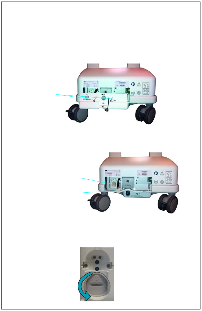
14‐14MaintenanceandTroubleshooting ExpressionMR400InstructionsforUse
ToreplacetheO2sensor.
Step Action
1TurnofftheMR400.
2Ensurethatanygassamplinglinehasbeendisconnectedfromthe
watertraponthepatientconnectionpanel.
3 Removethetwoscrewsthatsecuretheservicepanelcovertothe
backoftheWPUandthenremovetheservicepanelcover.
4LocatethesensortoolandtheO2sensorport.
5PlacethesensortoolintotheslotintheO2sensor,thenturnthe
sensorcounterclockwiseuntilitdisengagesfromthesensorport.
Screws Service panel
cover
O2 sensor
O2 tool
Slot
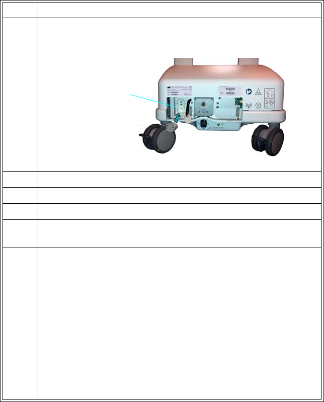
ExpressionMR400InstructionsforUseMaintenanceandTroubleshooting14‐15
Updating Software
Asrevisionstothesoftwarebecomeavailable,theMR400canbeupdated;refertotheservice
manual(REF989803181911).Itisrecommendedthatyoubackupyoursettingspriortoupdating
software,sothattheycanberestoredafterward;seeEditUserSettingsonpage3‐15.
6InsertanewO2sensorintothesensorportandthen,usingthe
sensortool,turnthesensorclockwiseuntilsecure.
7Replacetheservicepanelcoverandsecureitusingthetwoscrews.
8Connectagassamplinglinetothewatertrap.
9TurnontheMR400.
10 TurnontheAgentsparameterandallowthesystemtorununtil
CO2WarmingUpisnolongerdisplayed.
11 CalibratetheO2sensorbyperformingthefollowingsteps:
a. PresstheMonitorkey.
b. OntheMonitorSetupmenu,selectService(Bio‐Med).
c. OntheService(Bio‐Med)menu,selectGasCal.
d. OntheGasCalmenu,selectO2Cal.
e. Whenprompted:FlowRoomAirfor10Seconds,Doyou
wishtocontinue?SelectYestoproceed.
ReadjustingCO2Zerowillbedisplayeduntilcalibrationis
complete.
Step Action
Sensor port
O2 sensor

14‐16MaintenanceandTroubleshooting ExpressionMR400InstructionsforUse
WARNING
When performing software updates (or upgrades) to the operating software of the MR400,
ensure that all remaining devices in the monitor’s network are at the same or a compatible
software revision level. Failure to observe this requirement could result in compatibility
conflicts, communication problems, et cetera.
Calibrating the Touch Screen
Note
Touch screen calibration is not routinely required, but will occur after installation of new
operating software.
Tocalibratethetouchscreenmenu,refertotheservicemanual(REF989803181911).
Troubleshooting
Methodsfortroubleshootingproblemswhentheequipmentseemstobefunctioningincorrectly
includeusingdisplayedalarmmessagesasastartingpoint;seechapter4foralisting.
Plannedmaintenanceanduserroutine‐testingarealsohelpfulwaystoconfirmdeviceoperations
ortohelpidentifyaproblem;seepage14‐4.
TroubleshootingtheMR400iscomprehensivelydescribedintheservicedocumentation.Philips
providesafullplannedmaintenanceandrepairserviceonbothacallbasisandacontractbasis.
FulldetailsareavailablefromyourPhilipsServiceOrganization.
Repair
TheMR400containsnouser‐serviceableparts.Allrepairsmustbeperformedbytrainedservice
personnel.Allrepairsonproductsunderwarrantymustbeperformedbyauthorizedpersonnel
orinanauthorizedServiceandRepairCenter.Unauthorizedrepairswillvoidthewarranty.
Circuitdiagrams,componentpartlists,descriptions,calibrationinstructions,andother
informationtoassistservicepersonnelintherepairoftheserviceablepartsofthedeviceare
availableintheservicemanual(REF989803181911)andonrequest.

ExpressionMR400InstructionsforUseMaintenanceandTroubleshooting14‐17
WARNINGS
•A shock hazard exists if the MR400 is operated without covers.
• Do not modify the MR400 Patient Monitoring System without authorization of the
Invivo (Royal Philips).
IftheMR400failstofunctionproperlyorrequiresmaintenance,contacttechnicalsupport:
1‐877‐INVIVO1
or
1‐877‐468‐4861
Internationally,pleasecontactyourKeyMarketrepresentative.Foracurrentlisting,goto
www.invivocorp.com
CAUTIONS
• This product, or any of its parts, must not be repaired other than in accordance with written
instructions provided by Invivo (Royal Philips), or altered without prior written approval.
• No repair should ever be undertaken or attempted by anyone not having a thorough
knowledge of the repair of Invivo (Royal Philips) patient monitoring systems. Only replace
damaged parts with components manufactured or sold by Invivo (Royal Philips). Contact
the Technical Service and Repair Center for assistance and service.
• The user of this product shall have the sole responsibility for any malfunction which results
from improper use, faulty maintenance, improper repair, damage, or alteration by anyone
other than Invivo (Royal Philips) or its authorized service personnel.
Environmental Requirements
PhilipsMedicalSystemsisconcernedtohelpprotectthenaturalenvironment,andtohelp
ensurecontinuedsafeandeffectiveuseofthisproduct,throughpropersupport,maintenance
andtraining.
ThereforePhilipsproductsaredesignedandmanufacturedtocomplywithrelevantguidelinesfor
environmentalprotection.Aslongastheproductisproperlyoperatedandmaintained,it
presentsnoenvironmentalrisks.However,theproductmaycontainmaterial(s),whichcouldbe
harmfultotheenvironmentifdisposedofincorrectly.Useofsuchmaterial(s)isessentialto
performingthefunctionsoftheproduct,andtomeetingstatutoryandotherrequirements.
ThissectionoftheInstructionsforUseisdirectedmainlyattheuser/owneroftheproduct.
Operatorsarenotusuallyinvolvedindisposal,exceptinthecaseofcertainbatteries;seepage
14‐22forthosedetails.

14‐18MaintenanceandTroubleshooting ExpressionMR400InstructionsforUse
Passing the Product on to another User
Ifthisproductpassestoanotheruser,itmustbeinitscompletestate,includingallproduct
supportdocumentation.MakethenewuserawareofthesupportservicesthatPhilipsMedical
Systemsprovidesforinstalling,commissioningandmaintainingtheproduct.Beforepassingon
theproductortakingitoutofservice,allpatientdatamustbe(backedupelsewhereifnecessary,
and)unrecoverablebedeletedontheproduct.
Itmustberememberedbyallexistingusersthatpassingonmedicalelectricalproductstonew
usersmaycreateserioustechnical,medicalandlegal(e.g.onprivacy)risks.Suchriskscanarise
eveniftheproductisgivenaway.Existingusersarestronglyadvisedtoseekadvicefromtheir
localPhilipsMedicalSystemsrepresentativebeforecommittingthemselvestopassingonany
product.Alternatively,contactthemanufacturer.
Oncetheproducthasbeenpassedontoanewuser,aprevioususermaystillreceiveimportant
safety‐relatedinformation,suchasbulletinsandfieldchangeorders.Inmanyjurisdictions,there
isacleardutyontheprevioususertocommunicatesuchsafety‐relatedinformationtonewusers.
PrevioususerswhoarenotableorpreparedtodothisshouldinformPhilipsMedicalSystems
aboutthenewuser,sothatPMScanprovidethenewuserwithsafety‐relatedinformation.
Packaging the MR400
TopackagetheMR400forshipment,usetheMR400packingmaterialstosafelytransportthe
monitor.Removeallaccessoriesbeforepackaging.
CAUTION
If shipment of the MR400 is required, batteries must be removed prior to transport and internal
batteries must be disconnected.
TopacktheMR400
Step Action
1InalocationoutsideoftheMRmagnetroom,ensurethattheAC
mainspowerisdisconnected.
2Ensurethatbothmainbatterieshavebeenremovedandthatthe
batteryswitchforthereservebatteriesisoff;seepage14‐2.
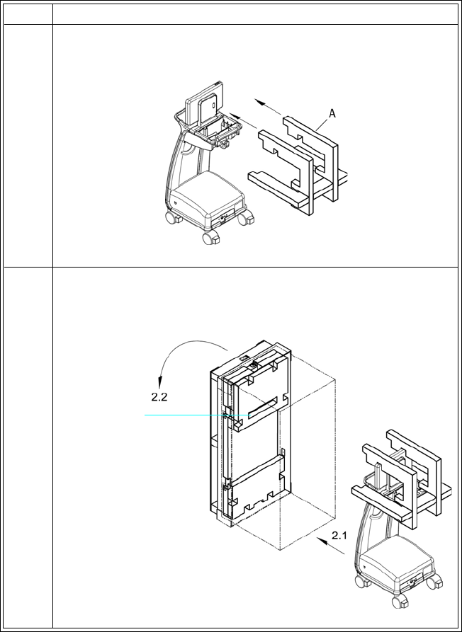
ExpressionMR400InstructionsforUseMaintenanceandTroubleshooting14‐19
3CoverthedisplaypanelandtheWPUwithprotectivefilmthen
installfoamAoverthedisplaypanel.
4Withthepackagingorientedsothattheslottedfoamwillbe
nearestthetop,raisethecrateintoanuprightposition.Rollthe
MR400intothecrateandthencarefullylowerthecrate.
Step Action
Slotted foam
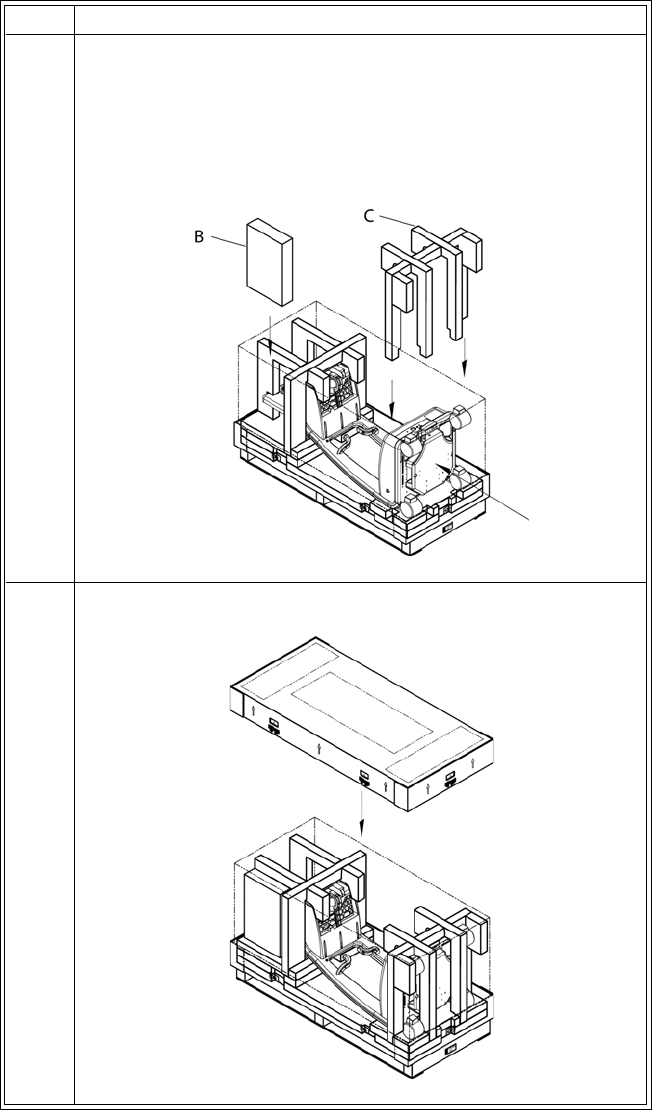
14‐20MaintenanceandTroubleshooting ExpressionMR400InstructionsforUse
5Ensurethattheguidehandleislocatedintheslottedfoam(see
step4)—ifnecessary,pushtheMR400fromthebottom.Packthe
MR400accessoriesintheaccessorybox(B)andthenplacethe
accessoryboxintothecrate,alongsidethedisplaypanelasshown
below.InsertfoamCovertheWPUandbetweenthebaseofthe
MR400andthecrate.
6Placethelidonthecrate.
Step Action

ExpressionMR400InstructionsforUseMaintenanceandTroubleshooting14‐21
Final Disposal of the Product
Finaldisposaliswhentheuserdisposesoftheproductinsuchawaythatitcannolongerbe
usedforitsintendedpurposes.
WARNING
Do not dispose of this product (or any parts of it) in industrial or domestic waste.
The product may contain materials and hazardous substances that can cause
serious environmental pollution. The system also contains privacy sensitive
information. It is advisable to contact your Royal Philips Service Organization
before disposing of this product.
PhilipsHealthcaresupportsusersin:
• Recoveringreusableparts.
• Recyclingofusefulmaterialsbycompetentdisposalcompanies.
•Safeandeffectivedisposalofequipment.
Foradviceandinformation,contactyourPhilipsServiceOrganizationfirst,orotherwisethe
manufacturer.
Disposal of the MR400 and Accessories
TheMR400cart,wirelessmodulesandaccessoriesaresubjecttostrictdisposalregulationsfor
userandenvironmentalsafety.Neverdisposeofwasteelectricalandelectronicequipmentas
7Installalltheclipsintothelidonthecrate,ensuringthateachis
lockedandthatthecrateissecure.
Step Action

14‐22MaintenanceandTroubleshooting ExpressionMR400InstructionsforUse
unsortedmunicipalwaste.Collectitseparatelysothatitcanbesafelyandproperlyreused,
treated,recycledorrecovered.
WARNING
To avoid contaminating or infecting personnel, the environment or other equipment, make
sure you disinfect and decontaminate the MR400 appropriately before disposing of it in
accordance with your country's laws for equipment containing electrical and electronic
parts. Do not dispose of this product (or any parts of it) in industrial or domestic waste. The
system may contain materials such as lead, tungsten or oil, or other hazardous substances
that can cause serious environmental pollution. The system also contains privacy sensitive
information. It is advisable to contact your Royal Philips Service Organization before
disposing of this product. You can disassemble the MR400 and accessories as described in
the service manual.
Fitting, Removing and Disposing of Batteries
REACHrequiresPhilipsHealthcare(PH)toprovidechemicalcontentinformationforSubstances
ofVeryHighConcern(SVHC)iftheyarepresentabove0.1%oftheproductweight.Components
withinelectricandelectronicequipmentmaycontainphthalatesabovethethreshold(e.g.,bis2‐
ethyl[hexyl]phthalate,CASnr.:117‐81‐7).TheSVHClistisupdatedonaregularbasis.Therefore,
refertothefollowingPhilipsREACHwebsiteforthemostup‐to‐datelistofproductscontaining
SVHCabovethethreshold:http://www.philips.com/about/sustainability/reach.page
Thelithiumbatteriesfoundinthesystemandsomeoftheaccessoriesoroptionalequipment
maybesubjecttostrictdisposalregulationsforuserandenvironmentalsafety.Observeand
adheretoyourcurrentlocalregulationswhendisposingofbatteries.
CAUTIONS
• Never heat or throw a battery into fire. Heating the battery will damage the safety circuitry,
which can cause rupture or ignition of the battery.
• Never disassemble a battery. The batteries contain hazardous material that must be recycled
or disposed of properly. (Refer to the disposal guidelines above.)

ExpressionMR400InstructionsforUseSpecificationsA‐1
APPENDIX A
Specifications
General
Patient Safety
ConformstoANSI/AAMIES60601‐1.CertifiedtoCAN/CSAC22.2No.60601‐1‐08;IEC60601‐1‐2
Conformsto93/42/EECasamendedby2007/47/EEC,MedicalDeviceDirective
Defibrillatorprotectionupto5KVDC
Accordingtothedegreeofingressprotection:RatedIP21
(Protectedagainstaccesstohazardouspartsandtheingressofsolidforeignobjectsgreaterthan12.5mm(0.5inch),
andagainstverticallydrippingliquid.)
Whereappropriate,theequipmentcomplieswithworldwidestandardsforsafetyandperformanceofeachsystem
feature,whenconsideringtheindicationsforusewithintheMRenvironment.Thisequipmentcomplieswiththe
followinginternationalindustrystandardsforsafetyandperformance:
•ISO14971,Medicaldevices‐Applicationofriskmanagementtomedicaldevices
•IEC60601‐1,MedicalElectricalEquipmentPart1:GeneralRequirementsforSafety(Amendment1)IEC60601‐
1,clause16,MedicalElectrical(ME)Systems
•ETSIEN300‐440‐1,ElectromagneticcompatibilityandRadiospectrumMatters(ERM);Shortrangedevices;
Radioequipmenttobeusedinthe1GHzto40GHzfrequencyrange
•ETSIEN300‐440‐2,ElectromagneticcompatibilityandRadiospectrumMatters(ERM);Shortrangedevices;
Radioequipmenttobeusedinthe1GHzto40GHzfrequencyrange
•ETSIEN301‐489‐1,ElectromagneticcompatibilityandRadiospectrumMatters(ERM);Electromagnetic
Compatibility(EMC)standardforradioequipmentandservices;Part1:Commontechnicalrequirements‐V1.5.1
•ETSIEN301‐489‐3,ElectromagneticCompatibilityandRadioSpectrumMatters(ERM);Electromagnetic
Compatibility(EMC)StandardforRadioEquipmentandServices;Part3:SpecificConditionsforShort‐Range
Devices(SRD)OperatingonFrequenciesbetween9KHzand40GHz‐V1.4.1
•EN980:Symbolsforuseinlabelingofmedicaldevices
•EN1041:Informationsuppliedbythemanufacturerofmedicaldevices
•BSEN12470‐4:2001+A1:2009,ClinicalThermometers–Part4:PerformanceofElectricalThermometersfor
ContinuousMeasurement
•IEC60068‐2‐1,EnvironmentalTesting–Part2‐1:Test–TestA:Cold
•IEC60068‐2‐2,EnvironmentalTesting–Part2‐2:Test–TestB:DryHeat
•IEC60068‐2‐6,EnvironmentalTesting–Part2:Tests–TestFE:Vibration(Sinusoidal)
•IEC60068‐2‐27,EnvironmentalTesting–Part2:Tests–TestEBandGuidance:Bump
•IEC60068‐2‐64,EnvironmentalTesting–Part2:TestMethodsTestFH:VibrationBroad‐bandRandom(Digital
Control)andGuidance
•IEC60601‐1‐2,MedicalElectricalEquipmentPart1‐2:GeneralRequirementsforSafety‐CollateralStandard:
ElectromagneticCompatibility‐RequirementsandTests

A‐2Specifications ExpressionMR400InstructionsforUse
•IEC60068‐2‐64,EnvironmentalTesting–Part2:TestMethodsTestFH:VibrationBroad‐bandRandom(Digital
Control)andGuidance
•IEC60601‐1‐2,MedicalElectricalEquipmentPart1‐2:GeneralRequirementsforSafety‐CollateralStandard:
ElectromagneticCompatibility‐RequirementsandTests
•IEC60601‐1‐6,MedicalElectricalEquipment‐Part1‐6:GeneralRequirementsforSafety‐CollateralStandard:
Usability
•IEC60601‐1‐8,MedicalElectricalEquipment–Part1‐8:GeneralRequirementsforBasicSafetyandEssential
Performance–CollateralStandard:GeneralRequirements,TestsandGuidanceforAlarmSystemsinMedical
ElectricalEquipmentandMedicalElectricalSystems
•IEC60601‐2‐27,ParticularRequirementsforSafety‐SpecificationforElectrocardiographicMonitoring
Equipment
•IEC60601‐2‐33,Particularrequirementsforthesafetyofmagneticresonanceequipmentformedicaldiagnosis
•IEC60601‐2‐34,MedicalElectricalEquipment–Part2‐34:ParticularRequirementsfortheSafety,Including
EssentialPerformance,ofInvasiveBloodPressureMonitoringEquipment
•IEC60601‐2‐49,MedicalElectricalEquipment‐Part2‐49:ParticularRequirementsfortheSafetyof
MultifunctionPatientMonitoringEquipment
•IEC80601‐2‐30,MedicalElectricalEquipment‐Part2‐30:ParticularRequirementsfortheSafety,Including
EssentialPerformance,ofAutomaticCyclingNon‐InvasiveBloodPressureMonitoringEquipment
•ISO80601‐2‐61,MedicalElectricalEquipmentParticularRequirementsfortheBasicSafetyandEssential
PerformanceofPulseOximeterEquipmentforMedicalUse
•ISO80601‐2‐55,MedicalElectricalEquipmentParticularRequirementsfortheBasicSafetyandEssential
PerformanceofRespiratoryGasMonitorsandPart2‐55
•DangerousGoodsRegulations2008,DangerousGoodsRegulations2008–UNID3090
•UNDOTT1‐T8,UNTransportTestingforSecondaryLithiumCells
•ISTAProcedure1A,FixedDisplacementVibrationandShockTestingforPackagedProductsweighing150lb(68
kg)orless
• Directive2011/65/EU,Restrictionoftheuseofcertainhazardoussubstancesinelectricalandelectronic
equipment(RoHS2)
•ISO10993‐1,BiologicalEvaluationofMedicalDevices‐Part1:EvaluationandTesting
•ISO10993‐5,BiologicalEvaluationofMedicalDevices‐Part5:TestsforCytotoxicity:Invitromethods
•ISO10993‐10,BiologicalEvaluationofMedicalDevices‐Part10:TestsforIrritationandDelayed‐Type
Hypersensitivity
•21CFRPart801,CodeofFederalRegulations–MedicalDevices:Labeling
•49CFRPart173.185,CodeofFederalRegulations–Transportation–OtherRegulationsRelatingto
Transportation–PipelineandHazardousMaterialsSafetyAdministration,DepartmentofTransportation–
HazardousMaterialsRegulations–Shippers‐GeneralRequirementsforShipmentsandPackagings–Non‐bulk
packagingforhazardousmaterialsotherthanclass1andclass7–Lithiumcellsandbatteries
• 1999/5/EC,R&TTEDirective(RadioandTelecommunicationsTerminalEquipment)
General

ExpressionMR400InstructionsforUseSpecificationsA‐3
• 2002/96/EC,DirectiveonWasteofElectricalandElectronicEquipment
• 2006/66/EC,BatteryDirective
•ANSI/AAMIBP22,BloodPressureTransducers
•ANSI/AAMIEC13,CardiacMonitors,HeartRateMeters,andAlarms
•ANSI/AAMIEC53,ECGtrunkcablesandpatientleadwires
•ASTME‐1112—2000,StandardSpecificationforElectronicThermometerforIntermittentDeterminationof
PatientTemperature
•ASTMF2052‐14,StandardTestMethodforMeasurementofMagneticallyInducedDisplacementForceon
MedicalDeviceinMREnvironment
•ASTMF2503‐13,StandardPracticeforMarkingMedicalDevicesandotherItemsforSafetyintheMR
Environment
•FCCPart15.249(47CFRPart15.249),RadioFrequencyDevices–Operationwithinthebands902‐928MHz,
2400‐2483MHz,5725‐5875MHz,and24.0‐24.25GHz
•UL2054,StandardforHouseholdandCommercialBatteries
•IEC62133,Secondarycellsandbatteriescontainingalkalineorothernon‐acidelectrolytes,Standardfor
HouseholdandCommercialBatteries
•RSS‐210,Issue7,Low‐powerLicense‐exemptRadioCommunicationDevices(AllFrequencyBands):Category1
Equipment
•SAAAS/NZS3200.1.2,MedicalElectricalEquipmentPart1‐2:GeneralRequirementsforSafety‐Collateral
Standard:ElectromagneticCompatibility‐RequirementsandTests
•ISO14155‐1,Clinicalinvestigationofmedicaldevicesforhumansubjects.Part1:Generalrequirements
•IEC62304,MedicalDeviceSoftware:Softwarelifecycleprocesses
•JIST0601‐2‐34,MedicalElectricalEquipment–Part2‐34:ParticularRequirementsfortheSafety,Including
EssentialPerformance,ofInvasiveBloodPressureMonitoringEquipment
•JIST1306,ContinuousMeasuringClinicalElectricalThermometers
•ISO80601‐2‐56,Medicalelectricalequipment.Part2‐56:Particularrequirementsforbasicsafetyandessential
performanceofclinicalthermometersforbodytemperaturemeasurement
Power Requirements, Cart
OperatingVoltageRange 100to240VAC,±10percent
FrequencyRange 50to60Hz,singlephase
Current 1.4A@100VAC/0.7A@240VAC
PowerConsumption,Maximum 65Watts
Protection Internallyfused(3.15A,slowblow@250VAC),AClineand
neutral
General

A‐4Specifications ExpressionMR400InstructionsforUse
Battery
TypeCart:Lithium‐Ion
Module:Lithiumpolymer
OperationTime
(Fullycharged)
Cart:Dependentuponenabledparametersandsettings:
•Alldisplays,alarms,andmonitoringfunctionscontinuously
for8hours
•ECG&SPO2continuouslyfor8hours
•CO2continuouslyfor6hours(withorwithoutAGENT)
•P1andP2continuouslyfor6hours
•AGENTanalysiscontinuouslyfor6hours
• Temperaturecontinuouslyfor6hours
•NIBPreadingsevery5minutesfor6hours
Module:Approximately8hours
ChargeTime Cart:Torechargeafullydischargedbatteryisapproximately12
hourswiththeMR400turnedoff.Batterychargetimeto90
percentofcapacityisapproximately6hours.
Module:Torechargeafullydischargedbatteryisapproximately4
hours.Batterychargetimeto90percentofcapacityislessthan4
hours.
MinimumVoltage
(Fornormaloperation)
Cart:14.4V
Module:3.7V
Capacity Cart:75Wh
Module:3.1Wh
Environment
OperatingTemperatureRange 10to35°C(50to95°F)
StorageandTransportTemperatureRange Batteries:0to40°C(32to104°F)
Cart:‐20to60°C(‐4to140°F)
Wirelessmodulesandallotheraccessoriesnotspecifiedbelow:
‐20to60°C(‐4to140°F)
ECGskinprepgel:Followinstructionsontube
Quadtrodes:10to32°C(50to90°F)
Transducerandcable(optional)(REF989803179721):‐15to60°C
(‐50to140°F)
O2sensor(AGENToption),StorageTemperature:+5to25°C(+41
to77°F);TransportTemperature‐40to50°C(‐40to122°F)
(Whenstoringortransportingintemperaturesbeyondtheranges
specifiedabove,removethedesignatedcomponentandstoreor
moveitappropriately.)
General

ExpressionMR400InstructionsforUseSpecificationsA‐5
RelativeHumidityRange 5to80percent,non‐condensing
PhilipsIBPTransducerandcable(optional):15to80percent,non‐
condensing
OperatingPressureRange Upto3,000m(9,842ft)abovesealevel(708mbaror531mmHg)
StorageandTransportPressureRange 708mbar(708hPAor531mmHg)to1020mbar(1020hPAor765
mmHg)
MRISystemRange 0.7to3.0Tesla,atRFpowerlevelsnotexceeding4W/kgSAR,and
7.2µTB1rmsinallorientations
Dimensions and Weights
(Allmeasurementsmadewithbatteriesbutwithoutaccessories;fullyloadedcartweightalsoprovided)
Height Cart:127.3cm(50.1inches)
WirelessECGpatientmodule:18.2cm(7.17inches)
WirelessSpO2patientmodule:13.0cm(5.13inches)
Width Cart:47.5cm(18.7inches)
WirelessECGpatientmodule:6.7cm(2.65inches)
WirelessSpO2patientmodule:6.5cm(2.55inches)
Depth Cart:55.9cm(22inches)
WirelessECGpatientmodule:3.1cm(1.24inches)
WirelessSpO2patientmodule:3.1cm(1.24inches)
Weight Cart:46.9kg(103.3pounds);fullyloaded:50.2kg(110.7pounds)
WirelessECGpatientmodule:340g(12ounces)
WirelessSpO2patientmodule:204g(7.2ounces)
Display
Type LiquidCrystalDisplay(LCD),touchscreen,color
DriveSystem a‐SiTFTactivematrix
ScreenSize 39.5cm(15.6inches)diagonal
AspectRatio 16:9
Area 344.2(H)by193.5(V)mm
Pixels 1366(H)by768(V)pixels
DotPitch 0.084(H)by0.252(V)mm
PixelPitch 0.252(H)by0.252(V)mm
ContrastRatio 500:1(typical)
Backlight LED
PolarizerSurface Anti‐glare
Tilt Adjustable,5°to35°
General

A‐6Specifications ExpressionMR400InstructionsforUse
SweepSpeed ForECG,SPO2,andIBP,aspeedof25mm/secondgives9.1
secondsofdisplaytime,while50mm/secondgives4.6seconds.
Forrespiration,aspeedof3.125,6.25,12.5or25mm/secondis
provided.
WaveformDisplayMode Fixedtrace,movingerasebar
WaveformDisplayHeight(ECG,SingleTrace) ≥40mm
WaveformDisplayHeight(ECG,DualTrace)≥20mm
WaveformDisplayHeight(SPO2,CO2,P1,P2) ≥25mm
WaveformDisplayLength ≥228mm
BatteryIndication Timeremaining,redlowwarning
AlarmLight,PriorityIndication High:Red,flashing,1.5Hzwitha50%dutycycle
Medium:Yellow,flashing,0.75Hzwitha50%dutycycle
INOP:Blue,steady
AlarmVisibility Legibleat1meter(assumingavisualacuityof20/20andwithno
lineofsightobstructions)
AlarmSoundVolume Atthemaximumsetting(10):86dB
AlarmSound,PriorityIndication Threetonesoffixedpitchmnemonicnotes:
High:ccc–cc
Medium:ccc
INOP:ec
Communication
Attenuation 110dBconducted
Displayed Information
Time Battery‐backedquartzcrystalclock
Alarms Highandlowlimitsselectableforpatientparameters
Note
No algorithms were used to determine the manufacturer
configured alarm presets.
ECG ECGwaveformscale,displayedleads(2)
General

ExpressionMR400InstructionsforUseSpecificationsA‐7
HeartRate Automaticmodeselectsthevitalsigntoprovidetheheartrate
accordingtovitalsignsourceavailabilityandpriority.Ifnosource
available(ifnovitalsignmeetsthecriteria,thentheheartrate
sourcewillbedisplayedasNoneandnoheartratewillbe
produced.
Manualmodeselectiontoprovidetheheartrateisalsoavailable.
PulseOximeter Pulserate,pulsewaveform(normalized)andpercentsaturation
Trends Heartrate,respirationrate,P1and/orP2(systolic,diastolic,
mean),NIBP(systolic,diastolic,mean),EtCO2,O2,N2O,SpO2,
andAgents
CO2 Bothend‐tidalandfractionalinspiredCO2
NIBP Pressures(systolic,mean,diastolic)andstatus
RespirationRate RespirationratederivedfrombellowsorCO2
N2O EtN2OavailableinAgentMACbox
FiN2Onotdisplayed
O2 Inspired,end‐tidal(averagedpercent)
AGENT Automaticidentificationofprimaryandsecondaryagents
(Desflurane,Isoflurane,Enflurane,HalothaneorSevoflurane)
displayingbothend‐tidal(Et)andfractionalinspired(Fi)
concentrations.
Temperature Body temperature(°Cor°F)
ECG
ECG Amplifier
Protectedagainstdefibrillatorandelectrosurgerypotentials
StandardLeadConfigurations I,II,III,AVR,AVL,AVF
LeadFail Passive,sensingsignalimbalance
ECGInputImpedance >2.5MΩ,single‐ended(accordingtoIEC60601‐2‐27,50.102.3)
ElectrodeContactImpedance 20Kohms@10Hz
Heart Rate
Resolution 1beatperminute(BPM)
PulseRateRange 30to250BPM(Adult)
30to300BPM(Neonate,Pediatric)
Accuracy ±1percentor±1BPM,whicheverisgreater.
Displayed Information

A‐8Specifications ExpressionMR400InstructionsforUse
Cardiotach
Sensitivity(Monitorfiltermode) Adultpatienttype:>200μV
Neonate/Pediatricpatienttype:>100μV
QRSDuration Adultpatienttype:70to120ms
Neonate/Pediatricpatienttype:40to120ms
Bandwidth(Monitorfiltermode) 0.5to40Hz
BaselineOffset Automaticallyremoved
TallT‐WaveRejectionCapabilityforHeartRate
Indication
2mVwitha1mVQRSamplitude(Monitormode)
Leads‐offSensing DetectionbyDCcurrentwaveformof<100nA,notapplied
Alarm Limits (HR)
Lower
Upper
Off,or30to250BPM
60to250BPM,oroff
Test/Calibrations
SquareWaveTestSignal 60BPM±1BPM,1mV±10percent
ECG Supplemental Information, as required by IEC 60601-2-27
HeartRate(HR)AveragingMethod Fifteen‐pointmedianfilteremployedwheretheBPMheartrateis
computedbytakingthemeanofthethreemiddleelements.
Updaterateofthedisplayis2Hz.
TimetoAlarmforTachycardia
B1‐VentTachycardia
1mVpp,206BPM
B2‐VentTachycardia
2mVpp,195BPM
Gain0.5(12.03,11.04,14.1,11.8,11.4)Average:12.1sec(The
monitoringsystemmaytemporarilyexitthealarmcondition
duringthearrhythmiawaveformduration.)
Gain1.0(11.9,11.6,9.2,9.6,10.9)Average:10.6seconds
Gain2.0(8.8,9.1,10.3,9.4,12.1)Average:9.9seconds
Gain0.5(9.0,10.4,12.3,8.1,10.4)Average:10.0seconds
Gain1.0(8.4,7.7,12.5,7.7,8.3)Average:8.9seconds
Gain2.0(9.7,12.6,8.9,11.8,8.3)Average:10.3seconds
Note
Measurements made in FILTER MODE - MONITOR, outside of the MR environment. The alarm condition response
time of some arrhythmia complexes may be affected by MRI gradient artifacts.
ResponseTimeofHeartRateMetertoChange
inHeartRate
HRchangefrom80to120BPM:8.3secaverage
HRchangefrom80to40BPM:7.9secaverage
ECG

ExpressionMR400InstructionsforUseSpecificationsA‐9
HeartRateMeterAccuracyandResponseto
IrregularRhythm
A1:Ventricularbigeminy:40BPM
A2:Slowalternatingventricularbigeminy:30BPM
A3:Rapidalternatingventricularbigeminy:115–125BPM
A4:Bidirectionalsystoles58–85BPM
Note
Measurements made in FILTER MODE - MONITOR, outside of the MR environment. The accuracy of the indicated
heart rate may be affected by MRI gradient artifacts.
Pulse Oximeter
Pulsetonepitchismodulatedbythesaturationvalue.
SaturationRange 1to100percent,inclusive
SaturationValueResolution 1percent
SaturationAccuracy ±3percentat70–100percent
PulseAccuracy ±2percentor±1beatperminute(BPM),whicheverisgreater
PulseRateRange 30to250BPM,inclusive
PulseRateResolution 1BPM
DataUpdatePeriod 5,10,or15seconds(accordingtotheSPO2AveragingTime
setting)
DataUpdatePeriodduringAlarm 9,14,or19seconds,maximum(4secondsplustheSPO2
AveragingTimesettingof5,10,or15seconds)
WavelengthRange 500to1000nm
Note
Information about wavelength range can be especially useful to clinicians.
EmittedLightEnergy <15mW
PulseOximeterCalibrationRange 70to100percent
Alarm Limits
Lower
Upper
Off,or50to100percent
70to100percent,oroff
ECG

A‐10Specifications ExpressionMR400InstructionsforUse
When“HR”isderivedfromSPO2
Lower
Upper
Off,or30to250BPM
60to250BPM,oroff
Note
Measurement validation: SPO2 accuracy validated in human studies against arterial blood sample reference measured with
a CO-oximeter. In a controlled desaturation study, healthy adult volunteers with saturation levels between 70–100 percent
SPO2 were studied. The population characteristics for those studies were:
• about 50% female and 50% male subjects
• 19 – 27 years of age
• light to black skin tones
Reference method for the computation of pulse rate accuracy made using an electronic pulse simulator. (A functional
tester cannot be used for accuracy assessment of a pulse oximeter monitor; however, it can demonstrate that a pulse
oximeter monitor reproduces a calibration curve that has been independently demonstrated to fulfill a particular
accuracy specification.)
SPO2 measurements are statistically distributed; therefore, in accordance to 80601-2-61:2011, it is possible that only
two-thirds of the measurements will fall within ± 3 percent of the value measured by the CO-Oximeter.
CO2 (Optional LoFlo)
Sidestream,non‐dispersiveinfraredabsorptiontechnique,includesmultiplefiltrationsystemandmicroprocessor
logiccontrolofsamplehandlingandcalibration.Methodfordeterminingend‐tidalCO2measurement:Measures
peakoftheend‐tidalCO2waveformevery20seconds.
Output CO2waveform,EtCO2andFiCO2measurementnumericvalues,
andrespirationrate
InitializationTime Waveformdisplayedinlessthan20seconds,atanambient
temperatureof25°C(77°F);fullspecificationsattainedwithin2
minutes
ZeroCalibrationInterval Automaticoruserrequested
CO2UnitofMeasure Millimetersofmercury(mmHg)orkilopascals*(kPa)
CO2Resolution 1mmHg(0.1kPa)
FlowRate 50mL/minute±10mL/minute
DataSampleRate 100Hz
End‐tidalCO2(EtCO2)MeasurementRange
(InwhichtheCO2accuracyspecificationismet)
0to76mmHg(0to10.1kPa)forrespirationratesrangingfrom4
to60breathsperminute,inclusive
Pulse Oximeter

ExpressionMR400InstructionsforUseSpecificationsA‐11
FractionalinspiredCO2(FiCO2)Measurement
Range
3to50mmHg(0.4to6.7kPa)
Method:LowestreadingoftheCO2waveformintheprevious20
seconds
CO2Accuracy
(Allmeasurementsatgastempof25°C)
±4mmHg(±0.5kPa)or±12percent,whicheverisgreater,after
thespecifiedwarm‐upperiod
CO2Stability
ShortTerm Drift
LongTermDrift
Nottoexceed0.8mmHg(0.1kPa)overa4‐hourperiod
Accuracyspecificationmaintainedovera120‐hourperiod
RespirationAccuracy ±1breathor±3percent,whicheverisgreater
RespirationResolution 1breathperminute
RespirationRateRange
(Inwhichtherespirationaccuracyspecification
ismet)
4to100breathsperminute,inclusive
Note
A simulator was used to simulate breathing rates and calibrated gas was flowed through the simulator and into the
system, and effects on accuracy were recorded to determine the rated respiration rate range and the corresponding
effects of end-tidal gas reading accuracy as a function of respiratory rate.
Accessoryusage Functionalwithoutchangingaccessoriesforaminimumof6
hours
SystemResponseandRiseTimes
(Asmeasuredfromthepatientgasinputofthe
completepneumaticcircuit,includingtubing,
from10–90percentofthemeasuredCO2lev‐
els)
AirwayAdapter Systemresponse:10.89seconds
Risetime:0.94seconds
CO2Cannula Systemresponse:12.44seconds
Risetime:1.12seconds
DividedCannulaSystemresponse:16.17seconds
Risetime:2.01seconds
CO2 (Optional LoFlo)

A‐12Specifications ExpressionMR400InstructionsforUse
Compensations
(AutomaticCO2ambientpressure
compensation400–800mmHg[53.3–106.6
kPa])
Forend‐tidalO2balancegas(N2,N2O,O,He)andanesthetic
agentsB
Usesgascompensationinformationtocorrecttherawcarbon
dioxidevalue
AnestheticAgentEffects
(MACLevels)
AnestheticAgentSensitivityA(uncompensated):Accuracy
specificationwillbemaintainedforhalogenatedanesthetic
agentspresentatacceptedMAC(MinimumAlveolar
Concentration)clinicallevels.
AnestheticAgentSensitivity(compensated):Testingatagent
levelsdefinedbyacceptedregulatorystandards(60601‐2‐55)
Cross‐sensitivityCompensationError
(Additionalworstcaseerrorwhen
compensationforO2,N2O,anestheticagents,
orheliumiscorrectlyselectedfortheactual
fractionalgasconstituentspresent.)
0to40mmHg:±1mmHgadditionalerror
(0to5.3kPa:±0.1kPaadditionalerror)
41to70mmHg:±2.5mmHgadditionalerror
(5.5to9.3kPa:±0.3kPaadditionalerror)
71to100mmHg:±4mmHgadditionalerror
(9.5to13.3kPa:±0.5kPaadditionalerror)
101to150mmHg:±5mmHgadditionalerror
(13.5to20kPa:±0.6kPaadditionalerror)
Quantitativeeffectsofgassamplehumidityor
condensate**:
0to40mmHg:±2mmHg
(0to5.3kPa:±0.2kPa)
41to70mmHg:±5percent
(5.5to9.3kPa:±5percent)
71to100mmHg:±8percent
(9.5to13.3kPa:±8percent)
101to150mmHg:±10percent
(13.5to20kPa:±10percent)
**Withappropriatecompensationsapplied
Note
There are no known adverse effects on stated performance due to cyclical pressure of up to 10 kPa (100 cmH2O).
CalibrationInterval Calibrationverificationmustbeperformedat1yearintervals.
CO2 (Optional LoFlo)

ExpressionMR400InstructionsforUseSpecificationsA‐13
*Forkilopascals(kPa),allow±1leastsignificantdigittoaccommodateround‐offerrorforcalculatedvalues.
A.
(FromISO80601‐2‐55.FDArecommendedforahealthy40‐yearoldmale.)
B.
Alarm Limits
End‐tidalCO2
Lower
Upper
Off,or5to60mmHg(Off,or0.7to8.0kPa)
5to90mmHg,oroff(0.7to12.0kPa,oroff)
FractionalinspiredCO2
Lower
Upper
Nolowalarm;
0to20mmHg,oroff(0to2.7kPa,oroff)
Respiration
Lower
Upper
Off,or4to40RPM
20to100RPM,oroff
GAS or Vapor Halothane Enflurane Isoflurane Desflurane Sevoflurane N2O
MAC Level, % vol fraction 0.77 1.70 1.15 6.00 2.10 105
Measured Quantitative Effects of Gas or Vapor
Gas N2O HAL ENF ISO SEVO Xenon Helium DES Ethanol Isopropanol Acetone Methane
Carbon
Dioxide
NE @
60%
NE
@
4%
NE
@
5%
NE
@ 5%
NE
@
5%
ME1
@
80%
NE @
50%
ME2
@
15%
NE @
0.1%
NE @
0.1%
NE @
0.1%
NE @
1%
No Effect (NE)
Minimal Effect 1 (ME1) = Negatively bias Carbon Dioxide values by up to an additional 5 mmHg at 38 mmHg
Minimal Effect 2 (ME2) = Concentrations greater than 5% will positively bias Carbon Dioxide values by up to an additional 3 mmHg at 38
mmHg
***Metered dose inhaler propellants: Unspecified
Invasive Blood Pressure (Optional)
Pressure Amplifier
IsolationVoltage 5KVDC
SignalRange ‐30to+250mmHg
Sensitivity 5µV/V/mmHg
GainAccuracy ±0.5percent
Bandwidth 0to10Hz(‐3dB)
CO2 (Optional LoFlo)

A‐14Specifications ExpressionMR400InstructionsforUse
TransducerOffsetRange ±300mmHg
Transducer (REF 989803179721)
OperatingPressure ‐50to300mmHg
OverpressureLimits ‐400to5000mmHg
Sensitivity 5µV/V/mmHg±1@6VDCand22°C(71.6°F)
ZeroOffset <25mmHg
ZeroDrift <2mmHgin8hours
InputImpedance 300to350ohms
Auto Zero
Range +300mmHg
ZeroAccuracy ±1.0mmHg
ResponseTime 1second,notifiesoperatorwhendone
Pressure Wave Display
NumberofChannels 0,1or2
ABP,PAPandLAP Numericdisplayofsystolic,meananddiastolicpressures
CVPandICP Numericdisplayofmeanpressureonly
Pressure Scale Ranges
(UserSelectable)
0to250mmHg
0to200mmHg
0to150mmHg
0to100mmHg
0to75mmHg
0to45mmHg
Pulse Rate (when derived from P1 or P2)
Range 30to250BPM
Accuracy ±2percentoffullscale
Resolution 1BPM
Alarm Delay
TransducerDisconnect Sixseconds
PressureDisconnect Sixseconds
HighandLowPressure Tenseconds
Alarm Limits
When“HR”isderivedfromP1orP2
Lower
Upper
Off,or30to250BPM
60to250BPM,oroff
Systolic,Mean,Diastolic
Lower
Upper
Off,or‐30mmHgto250mmHg(Off,or‐4.0to33.3kPa)
‐30mmHgto250mmHg,oroff(‐4.0to33.3kPa,oroff)
Invasive Blood Pressure (Optional)
ExpressionMR400InstructionsforUseSpecificationsA‐15
Transducer Adapter Cable Compatibility
InvasivepressureinputmateswithanAmphenolconnector(MS‐3106A14S‐6P).Withthisconnectorandthe
followingconnectioninformation,transduceradaptercablesmaybefabricatedororderedfromvarious
manufacturers.
ConnectorPinNumber SignalName
A‐Signal
B+Excitation
C+Signal
D‐Excitation
EShield
AGENT (Optional)
SideStream,non‐dispersiveinfrared(NDIR)absorptiontechnique,includingwatertrapfiltrationsystemand
microprocessorlogiccontrolofsamplehandlingandcalibration
Simultaneouslymeasuredgases Anytwoofthefollowing,inspiredorexpired,whilealsomeasuring
CO2,N2O,andO2:
Halothane
Isoflurane
Sevoflurane
Desflurane
Enflurane
MeasurementRange(aftermaximumwarm‐
upperiod)
Halothane:0to5.0Vol.%
Isoflurane:0to5.0Vol.%
Sevoflurane:0to8.0Vol.%
Desflurane:0to18.0Vol.%
Enflurane:0to5.0Vol.%
CarbonDioxide:0to10.0Vol.%
NitrousOxide:0to100Vol.%
Invasive Blood Pressure (Optional)

A‐16Specifications ExpressionMR400InstructionsforUse
Accuracy*(includesstabilityanddrift)Halothane:±0.15Vol.%at0to1.00Vol%
±0.20Vol%at1.00to5.00Vol%
Unspecified>5.00
Isoflurane:±0.15Vol.%at0to1.00Vol%
±0.20Vol%at1.00to5.00Vol%
Unspecified>5.00
Sevoflurane:±0.15Vol.%at0to1.00Vol%
±0.20Vol%at1.00to5.00Vol%
±0.40Vol%at5.00to8.00Vol%
Unspecified>8.00
Desflurane:±0.15Vol%at0to1.00Vol%
±0.20Vol%at1.00to5.00Vol%
±0.40Vol%at5.00to10.00Vol%
±0.60Vol%at10.00to15.00Vol%
±1.0Vol%at15.00to18.00Vol%
Unspecified>18.00
Enflurane:±0.15Vol.%at0to1.00Vol%
±0.20Vol%at1.00to5.00Vol%
Unspecified>5.00
CarbonDioxide:±0.10Vol%at0to1.00Vol%
±0.20Vol%at1.00to5.00Vol%
±0.30Vol%at5.00to7.00Vol%
±0.50Vol%at7.00to10.00Vol%
Unspecified>10.00
NitrousOxide:±2.00Vol%at0to20Vol%
±3.00Vol%at20.0to100Vol%
InterferenceGas CO2:N2O,O2,AnyAgent=0.1%ABSinaccuracyallowanceforeach
N2O:CO2,O2,AnyAgent=0.1%ABSinaccuracyallowanceforeach
Agents:CO2=0%ABSinaccuracyallowance
N2O,O2,2ndAgent=0.1%ABSinaccuracyallowanceforeach
FlowRate(fixed) 200±20ml/min(Adult,Pediatric)
150±15ml/min(Neonate)
Maximumspecifiedintervalforintervention
ofwater(hoursatspecifiedminimumsample
flowrate)
AGENTmode:Adultandpediatricis17hours@200ml/min,37°C,
100%RH;neonateis17hours@120ml/min,37°C,100%RH
CO2mode:8hours@50mL/min+/‐10ml/min
AGENT (Optional)

ExpressionMR400InstructionsforUseSpecificationsA‐17
SystemResponseandRiseTimes
(Asmeasuredfrompatientgasinputofthe
completepneumaticcircuit,includingtubing,
from10–90percentofmeasuredlevels)
Cannula,AdultHalothane—
Systemresponse:11.56seconds
Risetime:5.77seconds
Enflurane—
Systemresponse:7.55seconds
Risetime:1.75seconds
Isoflurane—
Systemresponse:6.71seconds
Risetime:0.88seconds
Sevoflurane—
Systemresponse:6.45seconds
Risetime:0.62seconds
Desflurane—
Systemresponse:6.63seconds
Risetime:0.57seconds
Oxygen—
Systemresponse:6.99seconds
Risetime:1.02seconds
Nitrousoxide—
Systemresponse:6.28seconds
Risetime:0.25seconds
CO2—
Systemresponse:6.62seconds
Risetime:0.61seconds
AGENT (Optional)

A‐18Specifications ExpressionMR400InstructionsforUse
Cannula,InfantHalothane—
Systemresponse:15.95seconds
Risetime:8.63seconds
Enflurane—
Systemresponse:11.98seconds
Risetime:4.75seconds
Isoflurane—
Systemresponse:9.26seconds
Risetime:1.70seconds
Sevoflurane—
Systemresponse:6.48seconds
Risetime:0.62seconds
Desflurane—
Systemresponse:6.47seconds
Risetime:0.61seconds
Oxygen—
Systemresponse:8.61seconds
Risetime:1.13seconds
Nitrousoxide—
Systemresponse:7.95seconds
Risetime:0.72seconds
CO2—
Systemresponse:6.51seconds
Risetime:0.48seconds
AGENT (Optional)

ExpressionMR400InstructionsforUseSpecificationsA‐19
DividedCannula,AdultHalothane—
Systemresponse:20.81seconds
Risetime:14.18seconds
Enflurane—
Systemresponse:13.83seconds
Risetime:7.11seconds
Isoflurane—
Systemresponse:10.99seconds
Risetime:3.91seconds
Sevoflurane—
Systemresponse:7.48seconds
Risetime:0.78seconds
Desflurane—
Systemresponse:7.38seconds
Risetime:0.64seconds
Oxygen—
Systemresponse:8.02seconds
Risetime:1.07seconds
Nitrousoxide—
Systemresponse:7.16seconds
Risetime:0.51seconds
CO2—
Systemresponse:7.57seconds
Risetime:0.64seconds
AGENT (Optional)

A‐20Specifications ExpressionMR400InstructionsforUse
DividedCannula,InfantHalothane—
Systemresponse:9.98seconds
Risetime:3.95seconds
Enflurane—
Systemresponse:7.32seconds
Risetime:1.37seconds
Isoflurane—
Systemresponse:6.75seconds
Risetime:0.89seconds
Sevoflurane—
Systemresponse:5.45seconds
Risetime:0.67seconds
Desflurane—
Systemresponse:6.25seconds
Risetime:0.60seconds
Oxygen—
Systemresponse:7.25seconds
Risetime:0.84seconds
Nitrousoxide—
Systemresponse:6.51seconds
Risetime:0.39seconds
CO2—
Systemresponse:5.49seconds
Risetime:0.49seconds
DataSampleRate 25Hz
FullAccuracyRespirationRate
(Rangepermittingspecifiedgasaccuracy)
2to60rpm
Note
A simulator was used to simulate breathing rates and calibrated gas was flowed through the simulator and into the
system, and effects on accuracy were recorded to determine the rated respiration rate range and the corresponding
effects of end-tidal gas reading accuracy as a function of respiratory rate.
End‐tidalgasreadings,calculationmethod EndtidalCO2concentrationreadingsareidentifiedbyusingthe
highestvalueofthetemporalCO2‐curve.Correspondingreadingsof
N2Oandanestheticagentsaretakenatthesamepointintime.End‐
tidalO2concentrationreadingsareidentifiedbytheO2meanvalue
duringtherespiratoryphaseasidentifiedbythetemporalCO2
curve.Oncecorrectlyidentified,thelowestO2concentration
readingduringthephasewillbepresentedasend‐tidalO2.
Tota l RespirationRange 2to100rpm;accuracyisunspecifiedfrom60to100rpm
AGENT (Optional)

ExpressionMR400InstructionsforUseSpecificationsA‐21
RelevantInterference 0.5mmHgequivalentwith37.5°CsaturatedwithH2O(0.1% relative
max)
DisplayResolution0.1percentvolume
MaximumWarm‐upTime10minutes;ISOaccuracyachievedin<45secondsofactivation
AutoIDThreshold(fullaccuracymode) PrimaryAgentID:0.15%
SecondaryAgentID:0.3%
MultipleAgentsAlarmThreshold0.3%(0.5%duringISOaccuracymode)or5%REL(10%forIsoflurane)
ofprimaryagentifprimaryagent>10%(ForHaladd0.1%ABSto
thresholdvalues)
CO2AmbientPressureCompensationRange 500mmHgto900mmHg
PressureCompensationUnaffectedbycyclicalpressuresofupto10kPaas,apartfromthe
describedautomaticpressurecompensation,thepumpautomati‐
callyregulatesflowsothatnotonlygasreadingsbutalsogassample
flowisunaffected
CalibrationInterval Calibrationverificationmustbeperformedat1yearintervals.
Alarm Limits
EtCO2
Lower
Upper
Off,or5to60mmHg(Off,or0.6–8.0kPa)
5to90mmHg,oroff(0.7–12.0kPa,oroff)
FiCO2
Lower
Upper
Nolowalarm;
0to20mmHg,oroff(0to2.7kPa,oroff)
FiN2O
Lower
Upper
Nolowalarm;
0to80percent
EtHalothane
Lower
Upper
Off,or0.1to5.0Vol.%
0.1to5.0Vol.%,oroff
FiHalothane
Lower
Upper
Off,or0.1to5.0Vol.%
0.1to5.0Vol.%,oroff
EtIsoflurane
Lower
Upper
Off,or0.1to5.0Vol.%
0.1to5.0Vol.%,oroff
AGENT (Optional)

A‐22Specifications ExpressionMR400InstructionsforUse
FiIsoflurane
Lower
Upper
Off,0.1to5.0Vol. %
0.1to5.0Vol. %,Off
EtEnflurane
Lower
Upper
Off,0.1to5.0Vol. %
0.1to5.0Vol. %,Off
FiEnflurane
Lower
Upper
Off,0.1to5.0Vol. %
0.1to5.0Vol. %,Off
EtSevoflurane
Lower
Upper
Off,0.1to8.0Vol. %
0.1to8.0Vol. %,Off
FiSevoflurane
Lower
Upper
Off,0.1to8.0Vol. %
0.1to8.0Vol. %,Off
EtDesflurane
Lower
Upper
Off,0.1to18.0Vol. %
0.1to18.0Vol. %,Off
FiDesflurane
Lower
Upper
Off,0.1to18.0Vol. %
0.1to18.0Vol. %,Off
FiO2
Lowerandupper 18to100percent
O2
Resolution 1percent
Range 0to100percent
SignalOutput(atconstanttemperatureand
pressure)
10mV±1.5mV@20°C/20.95%O2
MaximumResponseTime(21%to100%step
changethroughpatientsamplinglineasseen
inWPUgasmonitorwindow)
Adult/Pediatric<7.3seconds
Neonate:<8.2seconds
Accuracy(includesstabilityanddrift),full
scale*
±1%at0to40%
±2%at40to60%
±3%at60to80%
±4%at80to100%
*Gasmeasurementperformancerequirementsaremetafterthemaximumwarm‐upperiod.
AGENT (Optional)

ExpressionMR400InstructionsforUseSpecificationsA‐23
Offset ±1percent
O2InterferingGasEffects:
N2O
CO2
Halothane
Enflurane
Isoflurane
Desflurane
Sevoflurane
Acetone
Ethanol
Helium
Methane
NitricOxide
<0.3vol%@80vol%N2O
<0.3vol%@5vol%CO2
<0.3vol%@5vol%HAL
<0.3vol%@5vol%ENF
<0.3vol%@5vol%ISO
<0.3vol%@18vol%DES
<0.3vol%@8vol%SEV
<0.3vol%@1vol%Acetone
<0.3vol%@0.1vol%Ethanol
<0.3vol%@80vol%HE
<0.3vol%@0.1vol%Methane
<0.3vol%@50ppmNO
OxygenSensor,OperatingTemperature 15to35°C(59to95°F)
OxygenSensor,ExpectedOperatingLife Productlabeledwithause‐bydate;15monthsfrommanufacturing
date(2500hoursat100percentO2).Exchangerecommendedevery
12months.
CO2
Resolution 1percent
Range 0to100percent
Bellows Respiration
RespirationRateMeasurementRange 0to60breathsperminute
RespirationRateResolution 1breathperminute
RespirationRateAccuracy ±1breathperminute
Temperature (Optional)
(Allmeasurementsmadewithorwithoutasterilejacket)
Channel One
Units Celsius(°C)orFahrenheit(°F)
Range 20.0°Cto44.0°C(68.0°Fto111.2°F)
Resolution 0.1°C(0.1°F)
AGENT (Optional)

A‐24Specifications ExpressionMR400InstructionsforUse
Accuracy ±0.5°C(±0.9°F)
Confirmingchangesinameasurementagainstothervitalsignmea‐
surementsshouldbestandardroutineduringuse.
ResponseTime Themeasuringtimetoobtainasteady‐statereadingwithinthe
manufacturer’saccuracyspecificationsiswithin15seconds,
complianttoISO80601‐2‐56,Particularrequirementsforbasic
safetyandessentialperformanceofclinicalthermometersforbody
temperaturemeasurement.
NumericDisplayUpdateTime 2seconds
SensorType Fiber‐optic,multiple‐use(whenusedwithsingle‐usesterilizedjack‐
ets)
ApplicationSite Axillary,esophageal,rectal
MeasurementMode Direct
Alarm Limits
Lower
Upper
Off,or20.0to44.0°C(Off,or68.0to111.2°F)
20.0to44.0°C,oroff(68.0to111.2°F,oroff)
Non-Invasive Blood Pressure
Oscillometrictechnology(withaninflatablecuff)determinessystolic,diastolicandmeanarterialpressures
PatientTypes Adult,PediatricandNeonate
Pneumatic Systems
CuffInflationPressure Initial:165mmHg(22kPa)forAdult,130mmHg(17.3kPa)for
Pediatric,and100mmHg(13.3kPa)forNeonate;allpressuresare±
15mmHg(2kPa)
SubsequentinflationpressuresdeterminedbylastNIBP
measurement
OverpressureProtection Automaticcuffpressurereleaseifinflationpressureexceeds300
mmHg(40kPa)forAdultandPediatricmodes,and150mmHg(20
kPa)forNeonatemode
UnitofMeasure Millimetersofmercury(mmHg)orkilopascals*(kPa)
Measurement Range
Systolic
Adult
Pediatric
Neonate
30to270mmHg(4.0to36kPa)
30to180mmHg(4.0to24kPa)
30to130mmHg(4.0to17.3kPa)
Temperature (Optional)
(Allmeasurementsmadewithorwithoutasterilejacket)

ExpressionMR400InstructionsforUseSpecificationsA‐25
Mean
Adult
Pediatric
Neonate
20to255mmHg(2.7to34kPa)
20to160mmHg(2.7to21.3kPa)
20to120mmHg(2.7to16kPa)
Diastolic
Adult
Pediatric
Neonate
10to245mmHg(1.3to32.7kPa)
10to150mmHg(1.3to20kPa)
10to100mmHg(1.3to13.3kPa)
Accuracy
PressureMeasurementAccuracy Maximummeanerror±5mmHg(±0.6kPa)withastandarddeviation
oflessthan8mmHg(1kPa)
PressureMeasurementResolution 1mmHg(0.1kPa)
PressureTransducerRange 0to300mmHg(0to40kPa)
Modes
Manual Immediateuponoperatorcommand
Automatic Determinationsautomaticallymadewithselectableintervalsof1,2,
3,5,10,15,20,and30minutes
Non-Invasive Blood Pressure

A‐26Specifications ExpressionMR400InstructionsforUse
Notes
• The effectiveness of NIBP has not been established in the presence of any dysrhythmias included in the exclusion
criteria.
• The NIBP clinical study was performed on adult and pediatric patients with the following attributes:
– The effectiveness of NIBP has not been established in the presence of any dysrhythmias included in the
exclusion criteria.Gender: 61% male, 39% female.
– No patients less than 29 days of age.
– Patients with limb circumferences ranged from 10.5 cm to 39 cm, with a distribution of 46 percent below
25 cm and 7 percent above 35 cm.
– The arterial systolic pressure ranges from 58 mmHg to 211 mmHg, with an average of 115 mmHg and with
a distribution of 32.7 percent below 100 mmHg and 2.4 percent above 180 mmHg. The arterial diastolic
pressure ranges from 34 mmHg to 131 mmHg, with an average of 65 mmHg and with a distribution of 42.3
percent below 60 mmHg and 3.9 percent above 100 mmHg.
– Patients with any sign of arterial disease were excluded.
– Patients with a heart beat greater than 180 BPM were excluded.
– The radial artery was acceptable as a reference site for all patients but one which used the femoral artery.
– The effectiveness was not validated on pregnant, including pre-eclamptic, patient populations.
• The NIBP clinical study was performed on neonatal patients with the following attributes:
– No specified gender.
– All patients 28 days or less if born at term (37 gestation or more); otherwise, up to 44 gestational weeks.
– Patients with limb circumferences ranged from 5.75 cm to 13 cm with an average of 7.9 cm.
– The arterial systolic pressure ranged from 42 mmHg to 89 mmHg, with an average of 57 mmHg. The
arterial diastolic pressure ranged from 20 mmHg to 62 mmHg, with an average of 34 mmHg.
•Arterial reference sites included the umbilical, femoral, brachial and radial artery.
Non-Invasive Blood Pressure
ExpressionMR400InstructionsforUseSpecificationsA‐27
*Forkilopascals(kPa),allow±1leastsignificantdigittoaccommodateround‐offerrorforcalculatedvalues.
Alarm Limits
Systolic
Adult
Lower
Upper
Pediatric
Lower
Upper
Neonate
Lower
Upper
Mean
Adult
Lower
Upper
Pediatric
Lower
Upper
Neonate
Lower
Upper
Diastolic
Adult
Lower
Upper
Pediatric
Lower
Upper
Neonate
Lower
Upper
Off,or30to270mmHg(Off,or4.0to36.0kPa)
30to270mmHg,oroff(or4.0to36.0kPa,oroff)
Off,or30to180mmHg(Off,or4.0to24.0kPa)
30to180mmHg,oroff(or4.0to24.0kPa,oroff)
Off,or30to130mmHg(Off,or4.0to17.3kPa)
30to130mmHg,oroff(4.0to17.3kPa,oroff)
Off,or20to255mmHg(Off,or2.7to34.0kPa)
20to255mmHg,oroff(2.7to34.0kPa,oroff)
Off,or20to160mmHg(Off,or2.7to21.3kPa)
20to160mmHg,oroff(2.7to21.3kPa,oroff)
Off,or20to120mmHg(Off,or2.7to16.0kPa)
20to120mmHg,oroff(2.7to16.0kPa,oroff)
Off,or10to245mmHg(Off,or1.3to32.7kPa)
10to245mmHg,oroff(1.3to32.7kPa,oroff)
Off,or10to150mmHg(Off,or1.3to20.0kPa)
10to150mmHg,oroff(1.3to20.0kPa,oroff)
Off,or10to100mmHg(Off,or1.3to13.3kPa)
10to100mmHg,oroff(1.3to13.3kPa,oroff)
Non-Invasive Blood Pressure

A‐28Specifications ExpressionMR400InstructionsforUse
GatingOutputs
PinDesignator SignalName DescriptionandCharacteristics
A Digitalgatingpulse ECG/SPO2digitalgatingpulse:
•Peaktopeakvoltage:3.3Vto5.0V
•Pulseduration:10±3ms
•Delay<10ms,ECG:MonitorandDefaultfiltermodes
•Delay<12ms,ECG:Advanced1filtermode
•Delay<14ms,ECG:Advanced2filtermode
•Delay<50ms,SPO2
BSignalground Returnvoltagereferenceforallothersignalpins
CRESP1VAnalog Analogrespirationgatingwaveformsignal:
•Maximumoutputvoltage:±5V
•Maximumcurrent:5mA
•Peak‐to‐peaksignalvoltage:1V
•Delay=200ms
DECG1VAnalog AnalogECG1‐Voltwaveformsignal:
• Bandwidth0.5to40Hz(Monitorfiltermode)
• Outputsignalscaling:1V/mV
•Maximumoutputvoltage:±5V
•Maximumcurrent:5mA
•Delay<10ms
EP1200mVAnalog AnalogP1gatingwaveformsignal:
•Maximumoutputvoltage:200mV
FNegativegatingpulse ECG/SPO2negativedigitalgatingpulse:
•Peak‐to‐peaksignalvoltage:‐3.3Vto‐5.0V
•AllothersignalcharacteristicssameasPinA(seeabove)
GSPO240mVAnalog SPO2IR/redanaloggatingwaveformsignal:
•Signalscaling:1V/mV
•Maximumoutputvoltage:40mV
•Delay=250ms
HECG1mVAnalog ECGanaloggatingwaveformsignal:
•Signalscaling:1mV/mv
•Maximumcurrent:5mA
•Maximumoutputvoltage:20mV
• Bandwidth0.5to40Hz(Monitorfiltermode)
•Delay<10ms
JSPO22VAnalog SPO2IR/redanaloggatingwaveformsignal:
•Maximumoutputvoltage:2V
•Delay=250ms
K,L,M,N,O Unused Unusedpins
Gating connector pin-outs
ExpressionMR400InstructionsforUseWarrantyB‐1
APPENDIX B
Warranty
Warranty Statement
KoninklijkePhilipsN.V. warrantsthisproduct,otherthanitsconsumableparts,tobefreefrom
defectsinmaterialsandworkmanshipforaperiodoftwelve(12)monthsfromthedateof
originaldeliverytothebuyerortobuyer'sorder,providedthatsameisproperlyoperatedunder
conditionsofnormaluse,andthatperiodicmaintenanceandserviceisperformed.Thissame
warrantyismadeforaperiodofninety(90)daysonconsumableparts.Thiswarrantyshall
becomenullandvoidiftheMR400hasbeenrepairedbysomeoneotherthanKoninklijkePhilips
N.V. oriftheproducthasbeensubjecttomisuse,accident,negligenceorabuse.
KoninklijkePhilipsN.V.’ssoleobligationunderthiswarrantyislimitedtorepairinganMR400
whichhasbeenreportedtotheTechnicalServiceCenterduringnormalbusinesshoursand
shippedtransportationprepaid.KoninklijkePhilipsN.V. shallnotbeliableforanydamages
includingbutnotlimitedtoincidentaldamages,consequentialdamagesorspecialdamages.
Thiswarrantyisinlieuofanyotherwarranties,guaranteesorconditions,including
merchantabilityorfitnessforaparticularpurpose.Theremediesunderthiswarrantyare
exclusiveandKoninklijkePhilipsN.V. neitherassumesnorauthorizesanyonetoassumeforitany
otherobligationinconnectionwiththesaleorrepairofitsproducts.
KONINKLIJKEPHILIPSN.V. PRODUCTSCONTAINPROPRIETARYCOPYRIGHTEDMATERIAL.
ALLRIGHTSRESERVED
B‐2WarrantyExpressionMR400InstructionsforUse

ExpressionMR400InstructionsforUseRegulatoryInformationC‐1
APPENDIX C
Regulatory Information
European Union
Declaration of Conformity
ToobtainacopyoftheDeclarationofConformitytotheEuropeanUnionMedicalDevice
Directive(93/42/EEC)andRadio&TelecommunicationsTerminalEquipmentDirective(1999/5/
EC),and/orRestrictiononHazardousSubstance(RoHS)Directive,contacttheRegulatoryAffairs
DepartmentatInvivo:
407‐275‐3220
‐or‐
1‐800‐331‐3220(toll‐free)
Internationally,pleasecontactyourKeyMarketrepresentative.Gotowww.invivocorp.comfora
listing.Inaddition,copiesmaybeobtainedfromInCenter.
Authorized Representative
TheAuthorizedRepresentativefortheEuropeanUnion(asrequiredbytheMedicalDevice
Directive,93/42/EEC)isasfollows:
PhilipsMedizinSystemeBöblingenGmbH
Hewlett‐PackardStraße2
71034,Böblingen
Germany
Australia
TheAustraliaSponsorisasfollows:
PhilipsElectronicsAustraliaLtd
65EppingRoad,NorthRydeNSW2113
Australia
C‐2RegulatoryInformationExpressionMR400InstructionsforUse
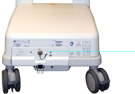
ExpressionMR400InstructionsforUseGatingFeatureD‐1
APPENDIX D
Gating Feature
ThegatingfeatureintheMR400outputsdataanddiscretesignalstotheMRIscannersystem
resultingfromthecollectionandprocessingofdatafromamonitoredparameter.Thescanner
systemusesthesesignalsanddatatopreciselycontrolthetimesthatitcollectsMRimagedata
fromthepatient.
TwotypesofdatacanbeoutputbythegatingfacilityoftheMR400:
•Analogwaveforms,whichareanalogelectronicrepresentationsofwaveformscollected
frommonitoredparameters;and,
•Gatingpulses,whicharediscreteelectronicsignalsthatindicatethatsomephysiological
eventassociatedwithamonitoredparameterhasoccurred.
MR400 Preparation for Gating
WhenpreparingtheMR400forgatingoftheMRsystem,ensurethatthecorrecttypeofgating
cableisconnectedbetweentherearpaneloftheMR400andtheMRsystem.
Gating Connector Pin-outs
GatingsignalsfromtheMR400areavailablethroughtheshieldedgatingconnectorlocatedon
therearpanelofthecart(seeabove).Connectionsaremadeusingagatingcable.Gatingcables
areavailableforeachmanufacturer’sMRIsystem(GEHorizonLX,SiemensHarmony,Siemens
1 Gating connector for connection of the gating cable to the MR system.
1

D‐2GatingFeatureExpressionMR400InstructionsforUse
Symphony,SiemensAlvanto,PhilipsIntera,etcetera;seepage1‐35).Fordetailedsignal
characteristicsofthegatingoutputs,seeA‐28.
Using the Gating Feature
ThegatingfeatureprovidesfacilitiesforlowlatencyMRItriggeringandsynchronizationbasedon
themeasuredECGorSPO2signal.DatameasuredandtransmittedbythewECGorwSpO2
moduleisprocessedbytheMR400andoutputatthegatingconnector;seepage1‐19forthe
location,andseethetableattheendofthisappendixforsignaldetails.(Signalscanalso
transmittedbytheoptionalwBTU.)
Using ECG Gating
ToreceiveECGgatingsignals
Step Action
1CheckthebatteryindicatorsonthewECGmoduletoensurethat
enoughchargeexistsinatleastoneoftheinstalledbatteries:
• Greenbatteryindicator=Chargesufficient;proceedtostep3.
•Redbatteryindicator=Chargelow;proceedtostep2.
Seepage2‐9fordetails.(Also,youcanreferencethestatus
informationpane;seepage2‐16.)
2 Accordingtotheredbatteryindicator(s)presentonthewECG
module,insertachargedmodulebatteryintothecorresponding
batterybay(s)andthenrecheckthebatteryindicator(s)toensurea
sufficientchargebeforeproceeding;seepage1‐24.
3CheckthenetworkchannelindicatoronthewECGmoduleto
ensurecommunicationisestablishedwiththeMR400:
• Steady=Goodcommunication;proceedtostep5.
• Flashing=Nocommunication;proceedtostep4.
Seepage2‐10fordetails.(Also,youcanreferencethestatus
informationpane;seepage2‐16.)
4Ensure
thatthewECGmoduleiswithin9.1m(30feet)ofthe
MR400,inthesameMRIroomorinthesameshieldedroom,andis
settothesamewirelessnetworkchannelusedbytheMR400;see
page1‐29.
5Ensurethattheleadcableisproperlyattachedtothepatient;see
AttachingtheECGLeadCableonpage5‐12.
(ECGoutputsareenabledbydefault;seepage5‐29.)
6ItmaybenecessarytouseT‐WaveSuppression,seepage5‐33.

ExpressionMR400InstructionsforUse GatingFeatureD‐3
7 Proceedaccordingtothetypeofgatingbeingused:
AnalogGating—To receivetheanalogECGgatingwaveform
throughtheMR400,ensurethatallofthefollowingconditions
havebeenmet:
•ThecorrectgatingcableisinstalledbetweentheMR400and
theMRsystem;
•ThesystemiscommunicatingwiththewECGmodule;
•ThewECGmoduleisproperlyattachedtothepatient;and,
•LeadFaildoesnotexistforthemeasuredECGsignal.
DigitalGating—ToreceivethedigitalECGgatingpulsefromthe
MR400,ensurethatallofthefollowingconditionshavebeenmet:
•ThecorrectgatingcableisinstalledbetweentheMR400and
theMRsystem;
•ThesystemiscommunicatingwiththewECGmodule;
•ThewECGmoduleisproperlyattachedtothepatient;
•LeadFaildoesnotexistforthemeasuredECGsignal;
•TheECGparameterhasbeenactivatedinthemenusystem;
and,
•TheECGsignalhasbeenselectedasthedigitalpulsesource,
asfollows:
a. SelecttheECGVSbox.
b. SelectGatingSource.
c. SelectECG.
Step Action

D‐4GatingFeatureExpressionMR400InstructionsforUse
Using SPO2 Gating
ToreceiveSPO2gatingsignals
Step Action
1CheckthebatteryindicatoronthewSpO2moduletoensurethat
enoughchargeexists:
• Greenbatteryindicator=Chargesufficient;proceedtostep5.
•Redbatteryindicator=Chargelow;proceedtostep4.
Seepage2‐11fordetails.(Also,youcanreferencethestatus
informationpane;seepage2‐16.)
2InsertachargedmodulebatteryintothewSpO2moduleandthen
recheckthebatteryindicatortoensureasufficientchargebefore
proceeding;seepage1‐26.
3CheckthenetworkchannelindicatoronthewSpO2moduleto
ensurecommunicationisestablishedwiththeMR400:
• Steady=Goodcommunication;proceedtostep7.
• Flashing=Nocommunication;proceedtostep6.
Seepage2‐11fordetails.(Also,youcanreferencethestatus
informationpane;seepage2‐16.)
4Ensurethatthecorrectgatingcableisinstalledbetweenthe
MR400andtheMRsystem.
5EnsurethatthewSpO2moduleiswithin9.1m(30feet)ofthe
MR400,inthesameMRIroomorinthesameshieldedroom,andis
settothesamewirelessnetworkchannelusedbytheMR400;see
page1‐29.
6EnsurethattheSPO2attachmentisproperlyattached;seeApply‐
ingtheSPO2AttachmenttothePatientonpage6‐3.
7 SelecttheSPO2VSbox(seepage6‐8).
TheSPO2menuappears.Currentsettingsaredisplayed.
8 SelectGatingSource.
TheGatingSourcemenuappears;seepage5‐15.
9 SelectPulse.
Thesettingisapplied.
ExpressionMR400InstructionsforUseGuidelinesandReferencesE‐1
APPENDIX E
Guidelines and References
Guidelines for the Prevention of Excessive Heating and Burns
Associated with Magnetic Resonance Procedures
Ingeneral,magneticresonance(MR)imagingisconsideredtobearelativelysafediagnostic
modality.However,theuseofradiofrequencycoils,physiologicmonitors,electronically‐
activateddevices,andexternalaccessoriesorobjectsmadefromconductivematerialshas
causedexcessiveheating,resultinginburninjuriestopatientsundergoingMRprocedures.
HeatingofimplantsandsimilardevicesmayalsooccurinassociationwithMRprocedures,but
thistendsbeproblematicprimarilyforobjectsmadefromconductivematerialsthathave
elongatedshapessuchasleads,guidewires,andcertaintypesofcatheters(e.g.,catheterswith
thermistorsorotherconductingcomponents).
Notably,morethan30incidentsofexcessiveheatinghavebeenreportedinpatientsundergoing
MRproceduresintheUnitedStatesthatwereunrelatedtoequipmentproblemsorthepresence
ofconductiveexternalorinternalimplantsormaterials[reviewofdatafilesfromU.S.Foodand
DrugAdministration,CenterforDevicesandRadiologicalHealth,ManufacturerandUserFacility
DeviceExperienceDatabase,MAUDE,http://www.fda.gov/cdrh/maude.htmlandU.S.Foodand
DrugAdministration,CenterforDevicesandRadiologicalHealth,MedicalDeviceReport,(http://
www.fda.gov/CDRH/mdrfile.html)].Theseincidentsincludedfirst,second,andthirddegree
burnsthatwereexperiencedbypatients.Inmanyofthesecases,thereportsindicatedthatthe
limbsorotherbodypartsofthepatientswereindirectcontactwithbodyradiofrequency(RF)
coilsorotherRFtransmitcoilsoftheMRsystemsortherewereskin‐to‐skincontactpoints
suspectedtoberesponsiblefortheseinjuries.
MRsystemsrequiretheuseofRFpulsestocreatetheMRsignal.ThisRFenergyistransmitted
readilythroughfreespacefromthetransmitRFcoiltothepatient.Whenconductingmaterials
areplacedwithintheRFfield,theresultmaybeaconcentrationofelectricalcurrentssufficient
tocauseexcessiveheatingandtissuedamage.Thenatureofhighfrequencyelectromagnetic
fieldsissuchthattheenergycanbetransmittedacrossopenspaceandthroughinsulators.
Therefore,onlydeviceswithcarefullydesignedcurrentpathscanbemadesafeforuseduring
MRprocedures.Simplyinsulatingconductivematerial(e.g.,wireorlead)orseparatingitfrom
thepatientmaynotbesufficienttopreventexcessiveheatingorburnsfromoccurring.
Furthermore,certaingeometricalshapesexhibitthephenomenonof“resonance”which
increasestheirpropensitytoconcentrateRFcurrents.Attheoperatingfrequenciesofpresent
dayMRsystems,conductingloopsoftensofcentimetersinsizemaycreateproblemsand,
therefore,mustbeavoided,unlesshighimpedanceisusedtolimitRFcurrent.Importantly,even
loopsthatincludesmallgapsseparatedbyinsulationmaystillconductcurrent.
Topreventpatientsfromexperiencingexcessiveheatingandpossibleburnsinassociationwith
MRprocedures,thefollowingguidelinesarerecommended:
E‐2GuidelinesandReferencesExpressionMR400InstructionsforUse
1. PreparethepatientfortheMRprocedurebyensuringthattherearenounnecessary
metallicobjectscontactingthepatient'sskin(e.g.,metallicdrugdeliverypatches,jewelry,
necklaces,bracelets,keychains,etcetera).
2. PreparethepatientfortheMRprocedurebyusinginsulationmaterial(i.e.,appropriate
padding)topreventskin‐to‐skincontactpointsandtheformationof“closed‐loops”from
touchingbodyparts.
3. Insulatingmaterial(minimumrecommendedthickness,1cm)shouldbeplacedbetween
thepatient'sskinandtransmitRFcoilthatisusedfortheMRprocedure(alternatively,the
RFcoilitselfshouldbepadded).Forexample,positionthepatientsothatthereisnodirect
contactbetweenthepatient'sskinandthebodyRFcoiloftheMRsystem.Thismaybe
accomplishedbyhavingthepatientplacehis/herarmsoverhis/herheadorbyusingelbow
padsorfoampaddingbetweenthepatient'stissueandthebodyRFcoiloftheMRsystem.
ThisisespeciallyimportantforthoseMRexaminationsthatusethebodycoilorotherlarge
RFcoilsfortransmissionofRFenergy.
4. Useonlyelectricallyconductivedevices,equipment,accessories(e.g.,ECGleads,
electrodes,etcetera),andmaterialsthathavebeenthoroughlytestedanddeterminedto
besafeandcompatibleforMRprocedures,aslistedinthisIFU.
5. CarefullyfollowspecificMRsafetycriteriaandrecommendationsforimplantsmadefrom
electrically‐conductivematerials(e.g.,bonefusionstimulators,neurostimulationsystems,
etcetera).
6. Beforeusingelectricalequipment,checktheintegrityoftheinsulationand/orhousingof
allcomponentsincludingsurfaceRFcoils,monitoringleads,cables,andwires.Preventive
maintenanceshouldbepracticedroutinelyforsuchequipment.
7. Removeallnon‐essentialelectricallyconductivematerialsfromtheMRsystem(i.e.,
unusedsurfaceRFcoils,ECGleads,cables,wires,etcetera).
8. KeepelectricallyconductivematerialsthatmustremainintheMRsystemfromdirectly
contactingthepatientbyplacingthermaland/orelectricalinsulationbetweenthe
conductivematerialandthepatient.
9. KeepelectricallyconductivematerialsthatmustremainwithinthebodyRFcoilorother
transmitRFcoiloftheMRsystemfromformingconductiveloops.Note:Thepatient's
tissueisconductiveand,therefore,maybeinvolvedintheformationofaconductiveloop,
whichcanbecircular,U‐shaped,orS‐shaped.
10. Positionelectricallyconductivematerialstoprevent“crosspoints”.Forexample,across
pointisthepointwhereacablecrossesanothercable,whereacableloopsacrossitself,or
whereacabletoucheseitherthepatientorsidesofthetransmitRFcoilmorethanonce.
Notably,eventhecloseproximityofconductivematerialswitheachothershouldbe
avoidedbecausesomecablesandRFcoilscancapacitively‐couple(withoutanycontactor
crossover)whenplacedclosetogether.
11. PositionelectricallyconductivematerialstoexitdownthecenteroftheMRsystem(i.e.,
notalongthesideoftheMRsystemorclosetothebodyRFcoilorothertransmitRFcoil).
ExpressionMR400InstructionsforUseGuidelinesandReferencesE‐3
12. Donotpositionelectricallyconductivematerialsacrossanexternalmetallicprosthesis
(e.g.,externalfixationdevice,cervicalfixationdevice,etcetera)orsimilardevicethatisin
directcontactwiththepatient.
13. Allowonlyproperlytrainedindividualstooperatedevices(e.g.,monitoringequipment)in
theMRenvironment.
14. Followallmanufacturerinstructionsfortheproperoperationandmaintenanceof
physiologicmonitoringorothersimilarelectronicequipmentintendedforuseduringMR
procedures.
15. ElectricaldevicesthatdonotappeartobeoperatingproperlyduringtheMRprocedure
shouldberemovedfromthepatientimmediately.
16. CloselymonitorthepatientduringtheMRprocedure.Ifthepatientreportssensationsof
heatingorotherunusualsensation,discontinuetheMRprocedureimmediatelyand
performathoroughassessmentofthesituation.
17. RFsurfacecoildecouplingfailurescancauselocalizedRFpowerdepositionlevelstoreach
excessivelevels.TheMRsystemoperatorwillrecognizesuchafailureasasetofconcentric
semicirclesinthetissueontheassociatedMRimageorasanunusualamountofimage
non‐uniformityrelatedtothepositionoftheRFcoil.
Theadoptionoftheseguidelineswillhelptoensurethatpatientsafetyismaintained,especially
asmoreconductivematerialsandelectronically‐activateddevicesareusedinassociationwith
MRprocedures.
References
BasheinG,SyroryG.Burnsassociatedwithpulseoximetryduringmagneticresonanceimaging.
Anesthesiology1991;75:382‐3.
BrownTR,GoldsteinB,LittleJ.Severeburnsresultingfrommagneticresonanceimagingwith
cardiopulmonarymonitoring.Risksandrelevantsafetyprecautions.AmJPhysMedRehabil
1993;72:166‐7.
ChouC‐K,McDougallJA,ChanKW.Absenceofradiofrequencyheatingfromauditoryimplants
duringmagneticresonanceimaging.Bioelectromagnetics1997;44:367‐372.
DempseyMF,CondonB.ThermalinjuriesassociatedwithMRI.ClinRadiol2001;56:457‐65.
DempseyMF,CondonB,HadleyDM.Investigationofthefactorsresponsibleforburnsduring
MRI.JMagnResonImaging2001;13:627‐631.
ECRI,HealthDevicesAlert.AnewMRIcomplication?HealthDevicesAlert.May27,pp.1,1988.
ECRI.ThermalinjuriesandpatientmonitoringduringMRIstudies.HealthDevicesAlert.1991;20:
362‐363.
E‐4GuidelinesandReferencesExpressionMR400InstructionsforUse
FinelliDA,RezaiAR,RuggieriPM,TkachJA,NyenhuisJA,HrdlickaG,SharanA,Gonzalez‐Martinez
J,StypulkowskiPH,ShellockFG.MRimaging‐relatedheatingofdeepbrainstimulation
electrodes:Invitrostudy.AmJNeuroradiol2002;23:1795‐1802.
HeinzW,FrohlichE,StorkT.Burnsfollowingmagneticresonancetomographystudy.(German)Z
Gastroenterol1999;37:31‐2.
http://www.MRIsafety.com
InternationalElectrotechnicalCommission(IEC),MedicalElectricalEquipment,Particular
requirementsforthesafetyofmagneticresonanceequipmentformedicaldiagnosis,
InternationalStandardIEC60601‐2‐33,2002.
JonesS,JaffeW,AlviR.Burnsassociatedwithelectrocardiographicmonitoringduringmagnetic
resonanceimaging.Burns1996;22:420‐1.
KanalE,ShellockFG.BurnsassociatedwithclinicalMRexaminations.Radiology1990;175:585.
KanalE,ShellockFG.Policies,guidelines,andrecommendationsforMRimagingsafetyand
patientmanagement.JMagnResonImaging1992;2:247‐248.
KeensSJ,LaurenceAS.BurnscausedbyECGmonitoringduringMRIimaging.Anaesthesia
1996;51:1188‐9.
KnoppMV,EssigM,DebusJ,ZabelHJ,vanKaickG.Unusualburnsofthelowerextremities
causedbyaclosedconductingloopinapatientatMRimaging.Radiology1996;200:572‐5.
KnoppMV,MetznerR,BrixG,vanKaickG.Safetyconsiderationstoavoidcurrent‐inducedskin
burnsinMRIprocedures.(German)Radiologe199838:759‐63.
KugelH,BremerC,PuschelM,FischbachR,LenzenH,TombachB,VanAkenH,HeindelW.
HazardoussituationintheMRbore:inductioninECGleadscausesfire.EurRadiol2003;13:690‐
694.
NakamuraT,FukudaK,HayakawaK,AokiI,MatsumotoK,SekineT,UedaH,ShimizuY.
Mechanismofburninjuryduringmagneticresonanceimaging(MRI)‐simpleloopscaninduce
heatinjury.FrontMedBiolEng2001;11:117‐29
NyenhuisJA,KildishevAV,FosterKS,GraberG,AtheyW.Heatingnearimplantedmedicaldevices
bytheMRIRF‐magneticfield.IEEETransMagn1999;35:4133‐4135.
RezaiAR,FinelliD,NyenhuisJA,HrdlickG,TkachJ,RuggieriP,StypulkowskiPH,SharanA,
ShellockFG.Neurostimulatorfordeepbrainstimulation:ExvivoevaluationofMRI‐related
heatingat1.5‐Tesla.JournalofMagneticResonanceImaging2002;15:241‐250.
SchaeferDJ.SafetyAspectsofradio‐frequencypowerdepositioninmagneticresonance.MRI
ClinicsofNorthAmerica1998;6:775‐789.
SchaeferDJ,FelmleeJP.Radio‐frequencysafetyinMRexaminations,SpecialCross‐Specialty
CategoricalCourseinDiagnosticRadiology:PracticalMRSafetyConsiderationsforPhysicians,
Physicists,andTechnologists,Syllabus,87thScientificoftheRadiologicalSocietyofNorth
America,Chicago,pp111‐123,2001.
ShellockFG.MagneticResonanceProcedures:HealthEffectsandSafety.CRCPress,LLC,Boca
Raton,FL,2001.
ExpressionMR400InstructionsforUseGuidelinesandReferencesE‐5
ShellockFG.MRsafetyupdate2002:Implantsanddevices.JournalofMagneticResonance
Imaging2002;16:485‐496.
ShellockFG.Radiofrequency‐inducedheatingduringMRprocedures:Areview.Journalof
MagneticResonanceImaging2000;12:30‐36.
ShellockFG.ReferenceManualforMagneticResonanceSafety:2003Edition,Amirsys,Inc.,2003.
ShellockFG,SlimpG.SevereburnofthefingercausedbyusingapulseoximeterduringMRI.
AmericanJournalofRoentgenology1989;153:1105.
ShellockFG,HatfieldM,SimonBJ,BlockS,WamboldtJ,StarewiczPM,PunchardWFB.
Implantablespinalfusionstimulator:assessmentofMRIsafety.JournalofMagneticResonance
Imaging2000;12:214‐223.
SmithCD,NyenhuisJA,KildishevAV.Healtheffectsofinducedelectricalfields:implicationsfor
metallicimplants.In:ShellockFG,ed.Magneticresonanceprocedure:healtheffectsandsafety.
BocaRaton,FL:CRCPress,2001;393‐414.
U.S.FoodandDrugAdministration,CenterforDevicesandRadiologicalHealth(CDRH),Medical
DeviceReport(MDR)(http://www.fda.gov/CDRH/mdrfile.html).Thefilescontaininformation
fromCDRH'sdeviceexperiencereportsondeviceswhichmayhavemalfunctionedorcauseda
deathorseriousinjury.ThefilescontainreportsreceivedunderboththemandatoryMedical
DeviceReportingProgram(MDR)from1984‐1996,andthevoluntaryreportsuptoJune1993.
Thedatabasecurrentlycontainsover600,000reports.
U.S.FoodandDrugAdministration,CenterforDevicesandRadiologicalHealth(CDRH),
ManufacturerandUserFacilityDeviceExperienceDatabase,MAUDE,(http://www.fda.gov/cdrh/
maude.html).MAUDEdatarepresentsreportsofadverseeventsinvolvingmedicaldevices.The
dataconsistsofallvoluntaryreportssinceJune,1993,userfacilityreportssince1991,distributor
reportssince1993,andmanufacturerreportssinceAugust,1996.
E‐6GuidelinesandReferencesExpressionMR400InstructionsforUse
Notes
Notes
Notes
Notes
Notes
Notes
Notes
Notes