Invixium Access MENXP Biometric Fingerprint Reader User Manual
Invixium Access Inc. Biometric Fingerprint Reader
User Manual
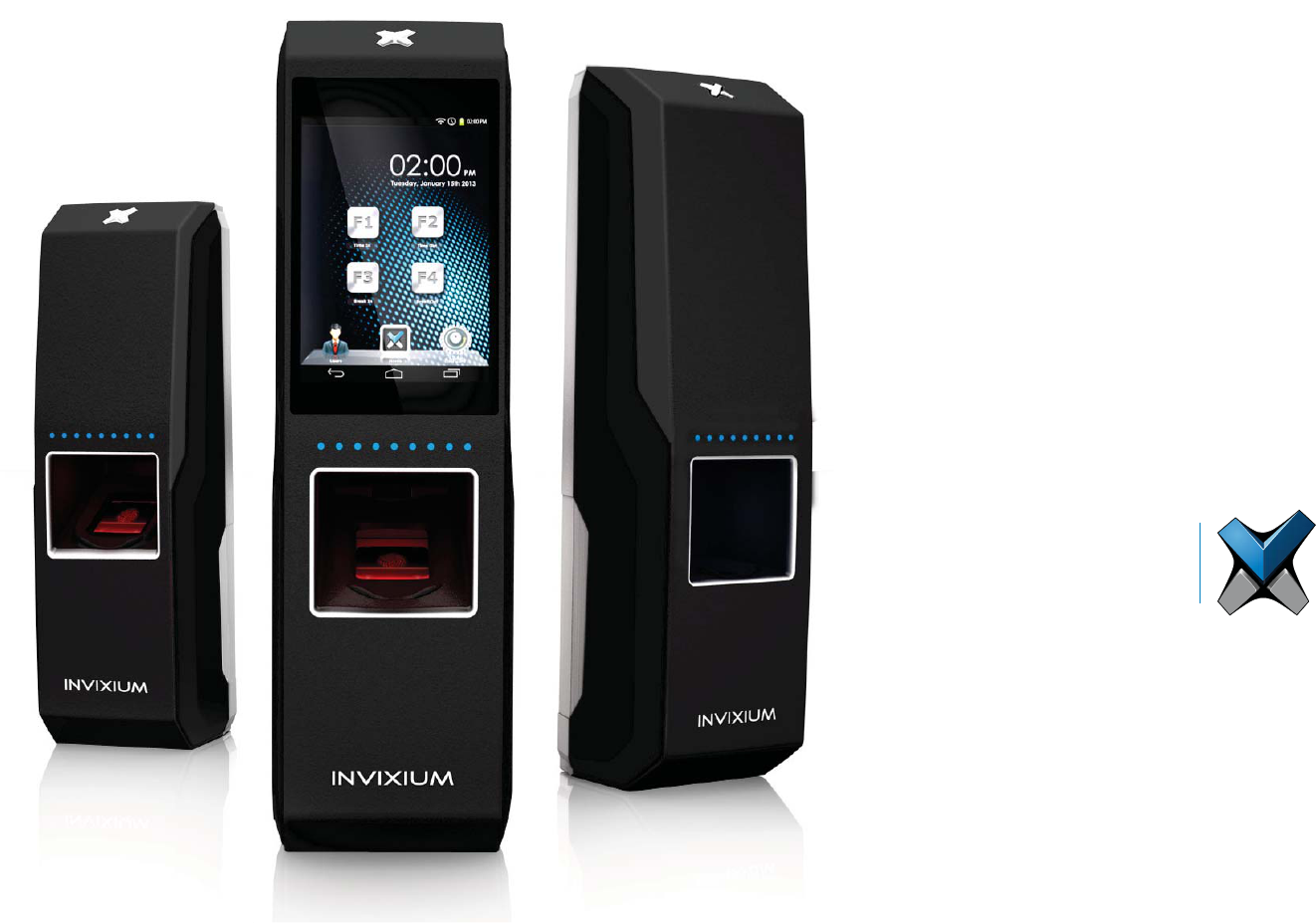
Installation
Guide
INVIXIUM
ACCESS

INVIXIUM
Copyright© 2013
Table of Contents
Glossary ..............................................................................................................................................................3
Earth Ground .............................................................................................................................................................................4
Device Handling and Cleaning ......................................................................................................................................................5
IXM INSTALL KIT Contents.........................................................................................................................................................6
IXM MYCRO ...........................................................................................................................................................................7
IXM SENSE .............................................................................................................................................................................9
IXM TOUCH ........................................................................................................................................................................... 11
I/O Cable: Top Connector Pin Out ............................................................................................................................................... 13
I/O Cable: Bottom Connector Pin Out .......................................................................................................................................... 14
Hardware Tools Required For Installation .................................................................................................................................... 15
Hardware Installation Steps ....................................................................................................................................................... 16
Connections for Power ............................................................................................................................................................... 20
Connections for Communication ................................................................................................................................................. 22
Connections for Operation ......................................................................................................................................................... 26
............................................................................................................................................................. 28
Software Installation System Requirements ................................................................................................................................. 29
Software Installation Steps ........................................................................................................................................................ 30
Notices ................................................................................................................................................................................... 32
Support ................................................................................................................................................................................... 35
2
INVIXIUM
Copyright© 2013
Glossary
ACP Access Control Panel
COM Common
DAC Door Access Control
DOS Door Open Schedule
EGND Earth Ground
ESD Electrostatic Discharge
GND Ground
IXM INVIXIUM
LED Light Emitting Diode
NC Normally Closed
NO Normally Open
OTG On-the-Go
RLY Relay
RX Receive
SGND Signal Ground
TX Transmit
USB Universal Serial Bus
WDATA Wiegand Data
WGND Wiegand Ground
VDC Volts Direct Current
VIN+ Power Positive (12-24 VDC)
VIN- Power Return
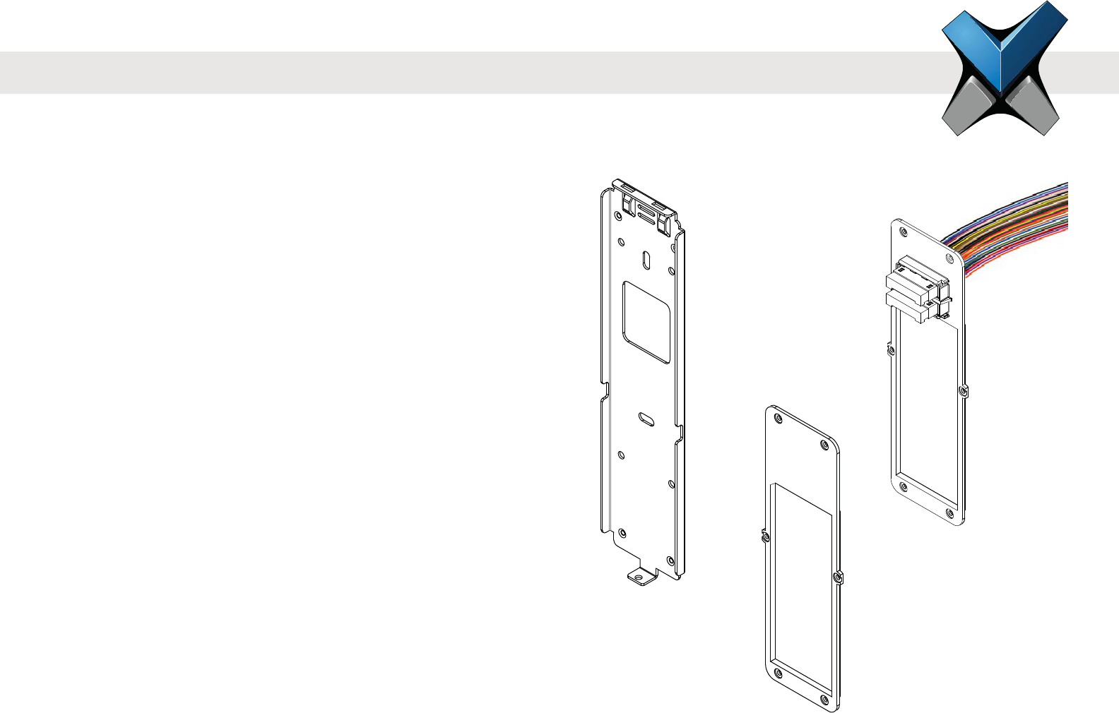
Temporary Back
Cover
Wired Back
Cover
Metal Mounting
Plate
3
INVIXIUM
Copyright© 2013
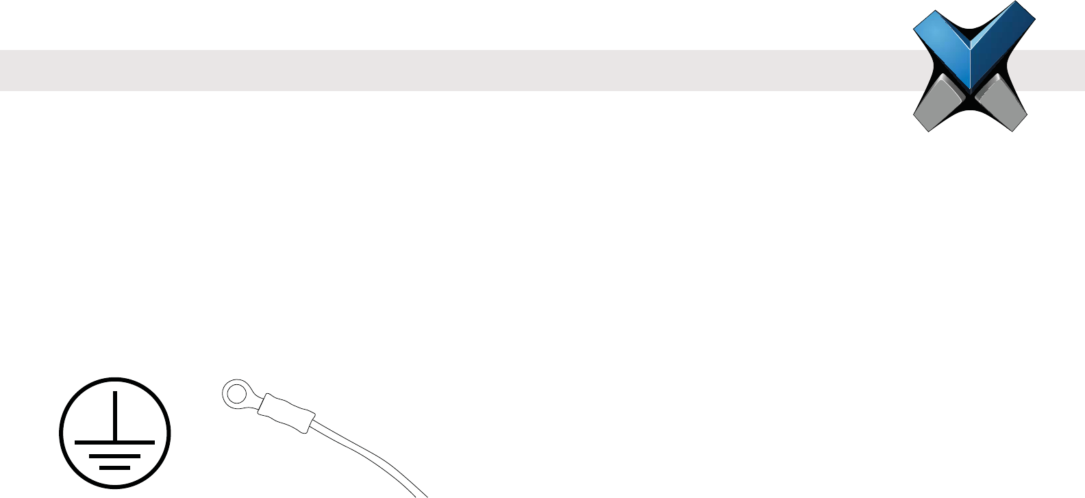
Earth Ground
For protection against ESD, which may cause damage or malfunction to the IXM device, Invixium recommends the use of the ground
connections between each IXM device and a high quality Earth Ground available at the install site. Please note that installation of any IXM
device should be performed by licensed electricians.
An Earth Ground wire with lug is provided in the IXM INSTALL KIT. The lug of the Earth Ground wire should be fastened with a screw to the
front of the mounting plate. The other end of the Earth Ground wire should be connected to the high quality Earth Ground connection on site.
When the IXM device is installed onto the mounting plate, this Earth Ground lug will make direct contact with the Metal Back plate of the IXM
device, thus allowing for proper grounding.
Please refer to page 15 for step-by-step instructions for mounting plate, device and Earth Ground wire installation.
4
Earth Ground WireEarth Ground

INVIXIUM
Copyright© 2013
Device Handling Do's
Handle with care, ensure not to drop or step on the device.
Perform occassional cleaning to eliminate a build-up of dust, dirt, oil and residual grime.
Device Handling Don'ts
Do not install in areas with direct sunlight, high levels of humidity,
Do not allow magnetic objects to come in close contact to any device.
Do not install near any heating elements or equipment.
Do not attempt to open or disassemble the device, as this will void the product warranty.
Do not deploy for any use other than its intended purpose.
Device Cleaning
The component that will require most frequent cleaning is the sensor, as it experiences the most contact. The cleaning should be performed
with care and attention, as improper cleaning may damage the sensor or surrounding components.
Follow the steps below for proper sensor cleaning procedure:
1. Lightly moisten a new cotton swab or lint free polishing cloth with water or isopropyl alcohol.
2. Gently wipe the surface of the sensor with the moistened cotton swab or cloth.
3. Finish the wiping the sensor again with a dry cotton swab or cloth.
WARNING
Do not use harsh or abrasive chemicals to clean the surface of the sensor, as this may cause permanent damage to the device.
Do not use sandpaper, steel wool, scouring pads, chlorine, ammonia, bleach, or any inappropriate products for cleaning.
5
INVIXIUM
Copyright© 2013 6
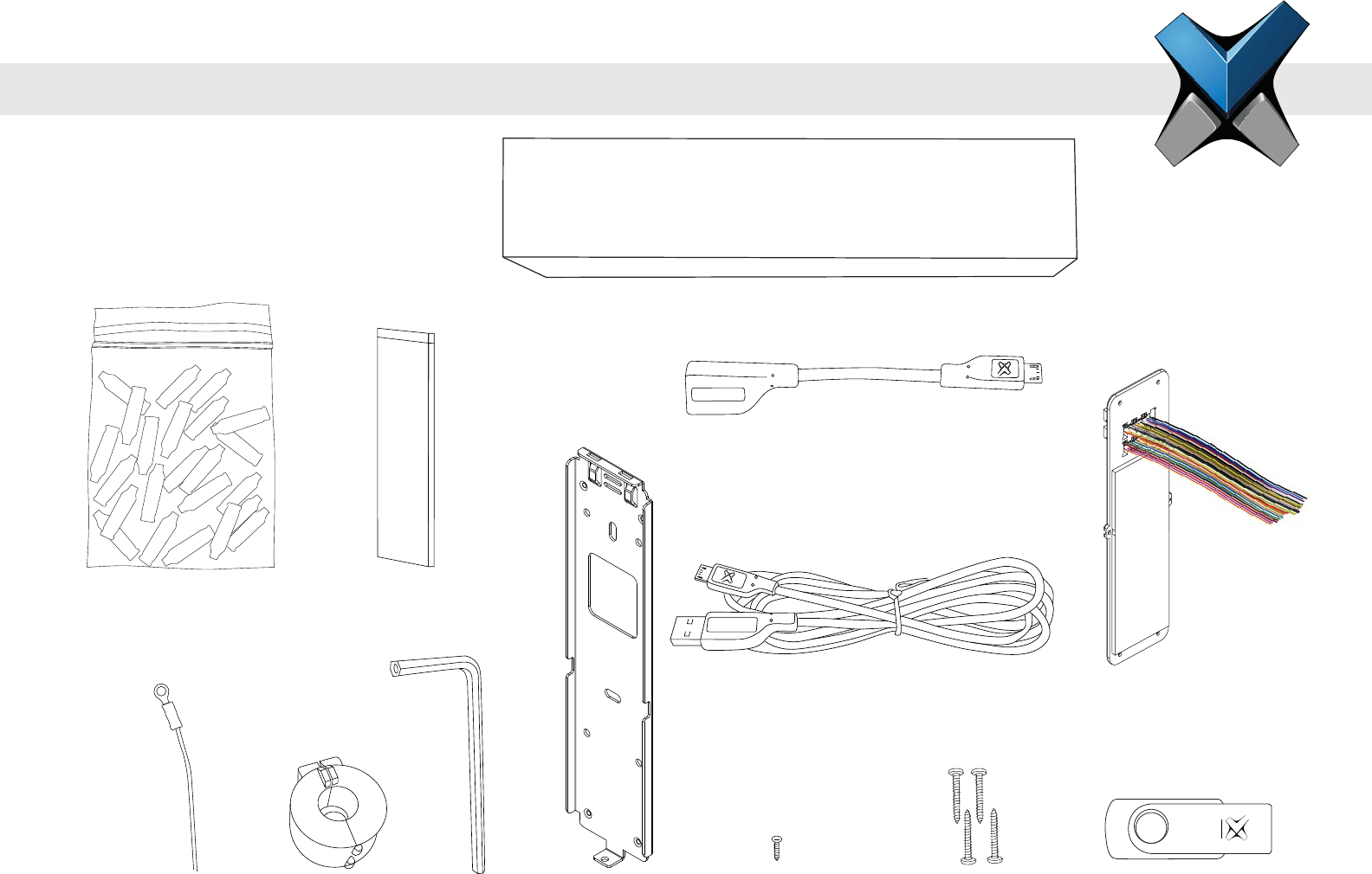
IXM INSTALL KIT
The IXM Install Kit includes:
INVIXIUM
ACCESS
DOLPHIN
DOLPHIN
DOLPHIN
DOLPHIN
DOLPHIN
DOLPHIN
DOLPHIN
DOLPHIN
DOLPHIN
DOLPHIN
DOLPHIN
DOLPHIN
DOLPHIN
DOLPHIN
INVIXIUM
INVIXIUM
Dolphin Crimps
(qty 24)
Lithium Battery
(IXM TOUCH only)
Metal Mounting
Plate
Earth Ground Wire Metal Mounting
Plate Screw
(qty 1)
Wall Mounting Screws
(qty 4)
Micro USB-On-the-Go Cable
Micro USB Extension
Cable (4 ft/1.2m) Wired Back Cover
USB Flash DriveFerrrite Core Hex Key
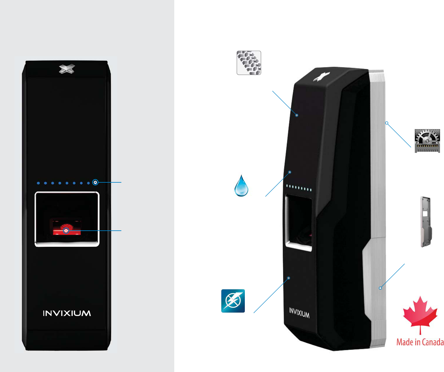
IXM MYCRO
Surge Protection as per
EN55024
More than IP65
Rugged Front Shell
Solid Metal Back
Plate
Industrial Grade
Connectors
7
Sensor
Multi-color
LEDs
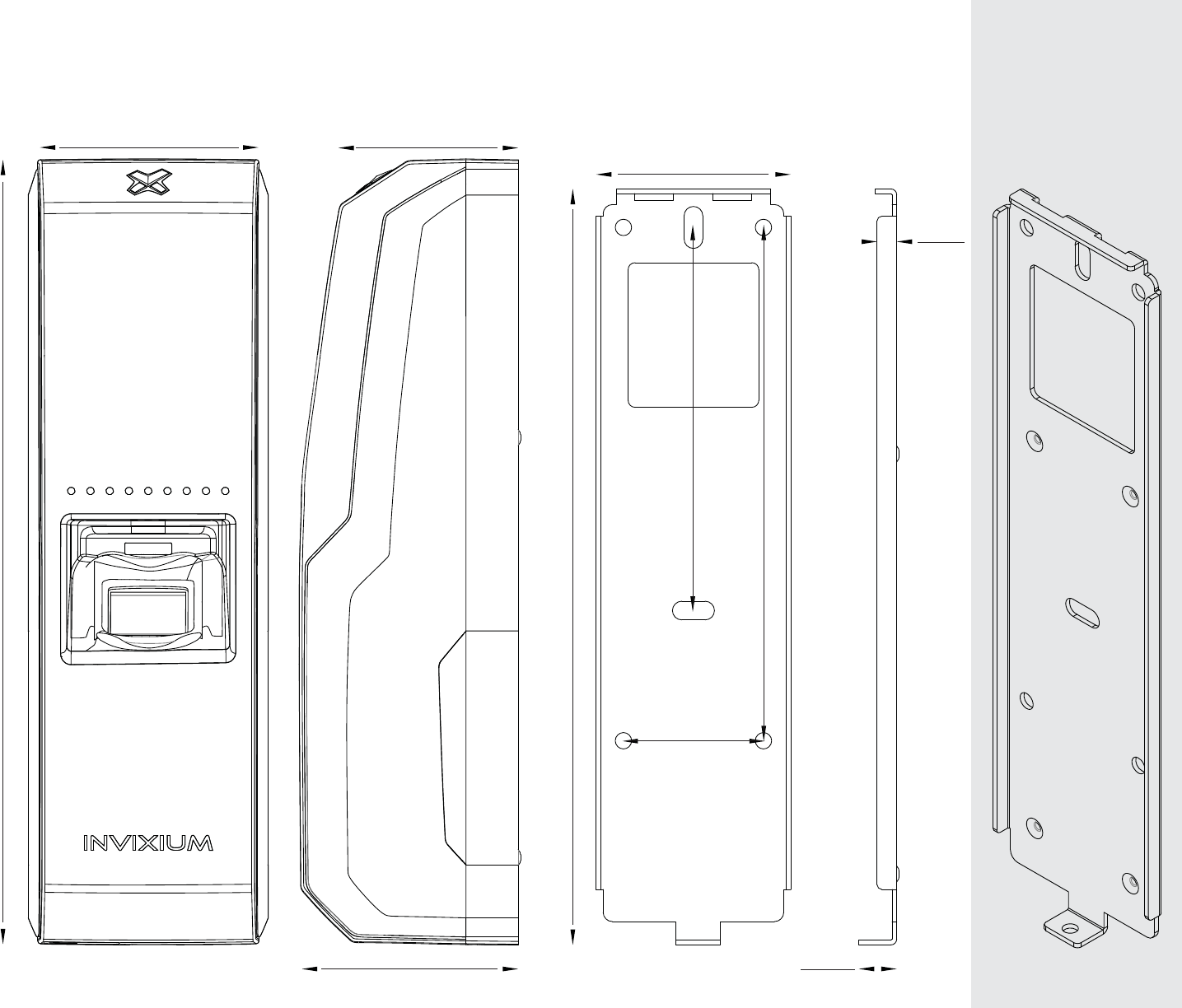
IXM MYCRO Product & Mounting Plate Actual Dimensions in mm
INVIXIUM recommends printing this page in Actual Size
162
41.70
30
82.1
110
48
168
Front View
38.5
46.3
Side View Front View
8.10
4.20
Side View
Angled
Front View
8
IXM SENSE
9
Surge Protection as per
EN55024
More than IP65
Rugged Front Shell
Multispectral
Fingerprint Imaging
Sensor
Solid Metal
Back Plate
Industrial Grade
Connectors
Lumidigm
Sensor
Multi-color
LEDs
IXM SENSE Product & Mounting Plate Actual Dimensions in mm
NVIXIUM recommends printing this page in Actual Size
199.7
Front View
46.08
51.85
Side View
45.20
194.9
Front View
9
5.40
Side View
Angled
Front View
49
30
82.1
110
10
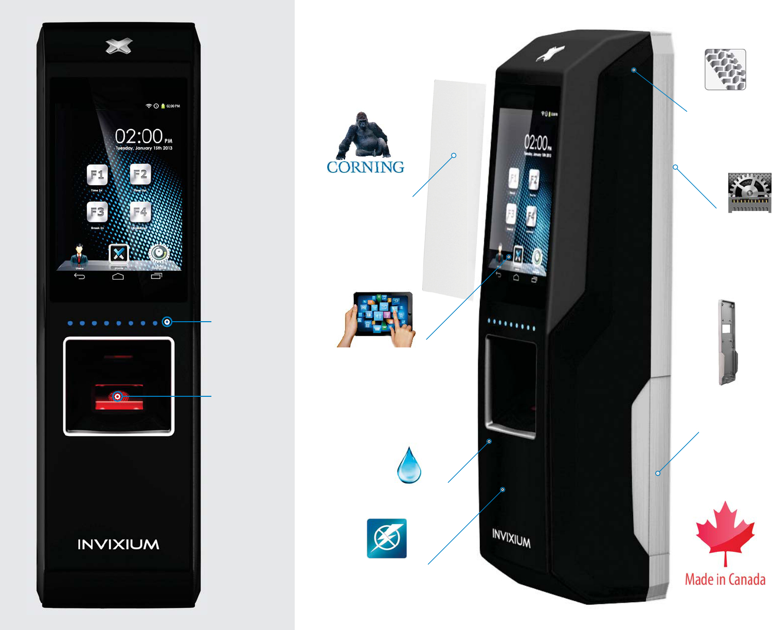
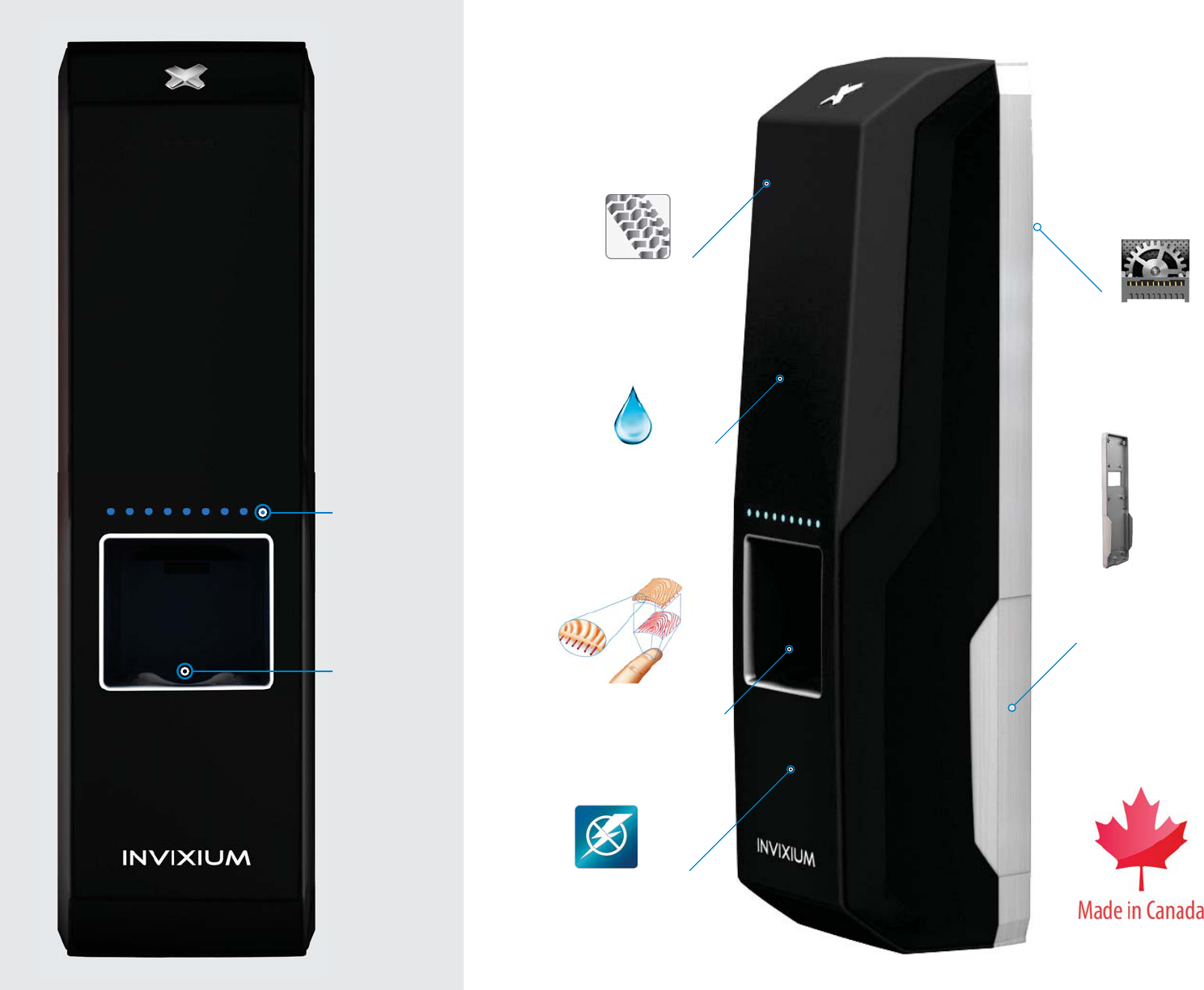
IXM TOUCH
11
Solid Metal
Back Plate
Industrial Grade
Connectors
Surge Protection as per
EN55024
More than IP65
Rugged
Front Shell
Super Strong
Protective Glass
Optically Bonded
Capacitive Touch Screen
Sensor
Multi-color
LEDs
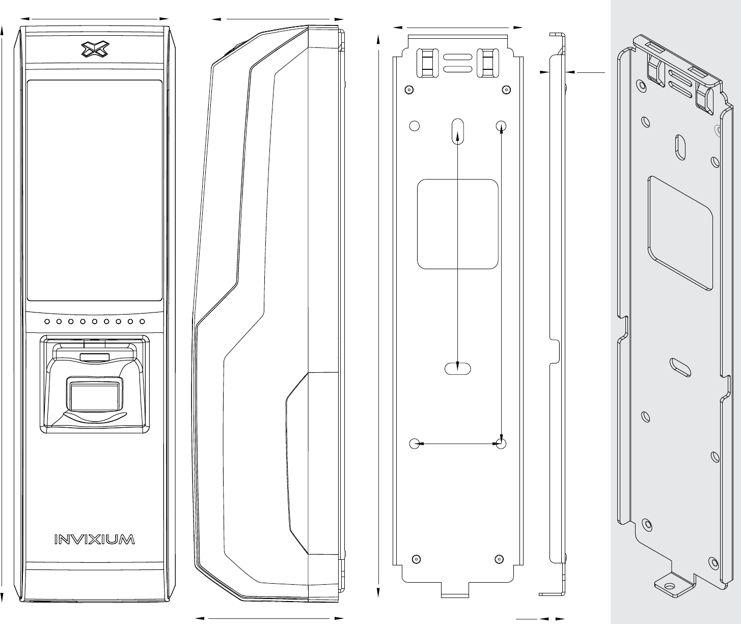
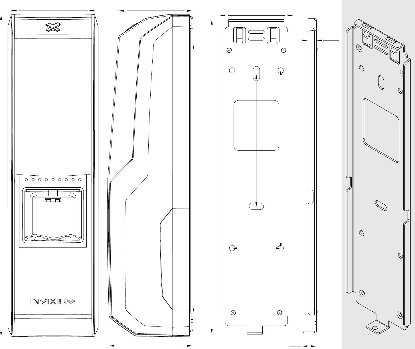
IXM TOUCH Product & Mounting Plate Actual Dimensions in mm
NVIXIUM recommends printing this page in Actual Size
49
199.7
Front View
46.08
51.85
Side View
45.20
194.9
Front View
9
5.40
Side View
Angled
Front View
82.1
110
30
12
INVIXIUM
Copyright© 2013
RLY_NC
RLY_NO
RLY_COM
ACP_LED2
ACP_LED_GND
ACP_LED1
DAC_IN1
DAC_IN3
DAC_IN2
DAC_GND
NC
DAC_OUT
SPI_GND
SPI_2
SPI_1
SPI_3
SPO_GND
SPO_2
SPO_3
SPO_1
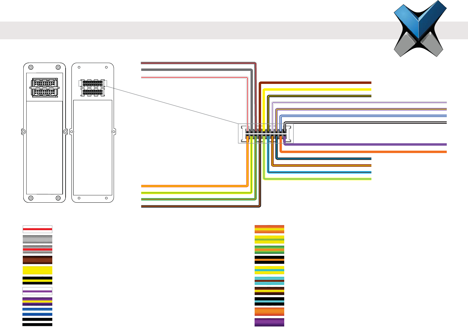
Application Label Pin
Door Access Control Output DAC_OUT 18
Reserved for Future (No Connect) N/C 20
Wire Color
Application Label Pin
Relay Normally Closed RLY_NC 1
Relay Common RLY_COM 3
Relay Normally Open RLY_NO 5
Access Control Panel LED 1 Feedback ACP_LED1 7
Access Control Panel LED 2 Feedback ACP_LED2 9
Ground for Access Control Panel LED Feedback ACP_LED_GND 11
Door Access Control Input 1 DAC_IN1 13
Door Access Control Input 2 DAC_IN2 15
Door Access Control Input 3 DAC_IN3 17
Ground for Door Access Control Inputs DAC_GND 19
Wire Color
I/O Cable: Top Connector Pin Out
Front View Back View
Wired Back Cover
13
INVIXIUM
Copyright© 2013
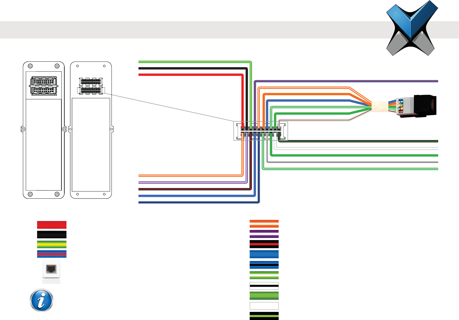
Application Label Pin
RS-232 Data Receive RS-232_RX 2
RS-232 Data Transmit RS-232_TX 4
Signal Ground SGND 6
RS-485 Non-Inverting Line RS-485+ (B) 8
RS-485 Inverting Line RS-485- (A) 10
Wiegand Data Input Line 0 WDATA_IN0 12
Wiegand Data Input Line 1 WDATA_IN1 14
Wiegand Data Output Line 0 WDATA_OUT0 16
Wiegand Data Output Line 1 WDATA_OUT1 18
Ground for Wiegand WGND 20
Application Label Pin
Power (+12-24 VDC) VIN+ 1
Power Ground VIN- 3
Earth Ground EGND 5
RS-485 Terminated (Optional)* RS-485_T 7
Ethernet or PoE† TCP/IP 9,11,13,
15,17,19
*This pin is optional and should be used in place of the
†PoE only available for IXM SENSE and IXM TOUCH
I/O Cable: Bottom Connector Pin Out
Wire ColorWire Color
RJ45 Receptacle
WGND
WDATA_OUT0
WDATA_IN0
WDATA_OUT1
WDATA_IN1
RS-485+ (B)
RS232_TX
RS-485- (A)
SGND
RS232_RX
VIN+
EGND
VIN-
TCP/IP
RS-485_T
Front View Back View
Wired Back Cover
NOTE
14
INVIXIUM
Copyright© 2013
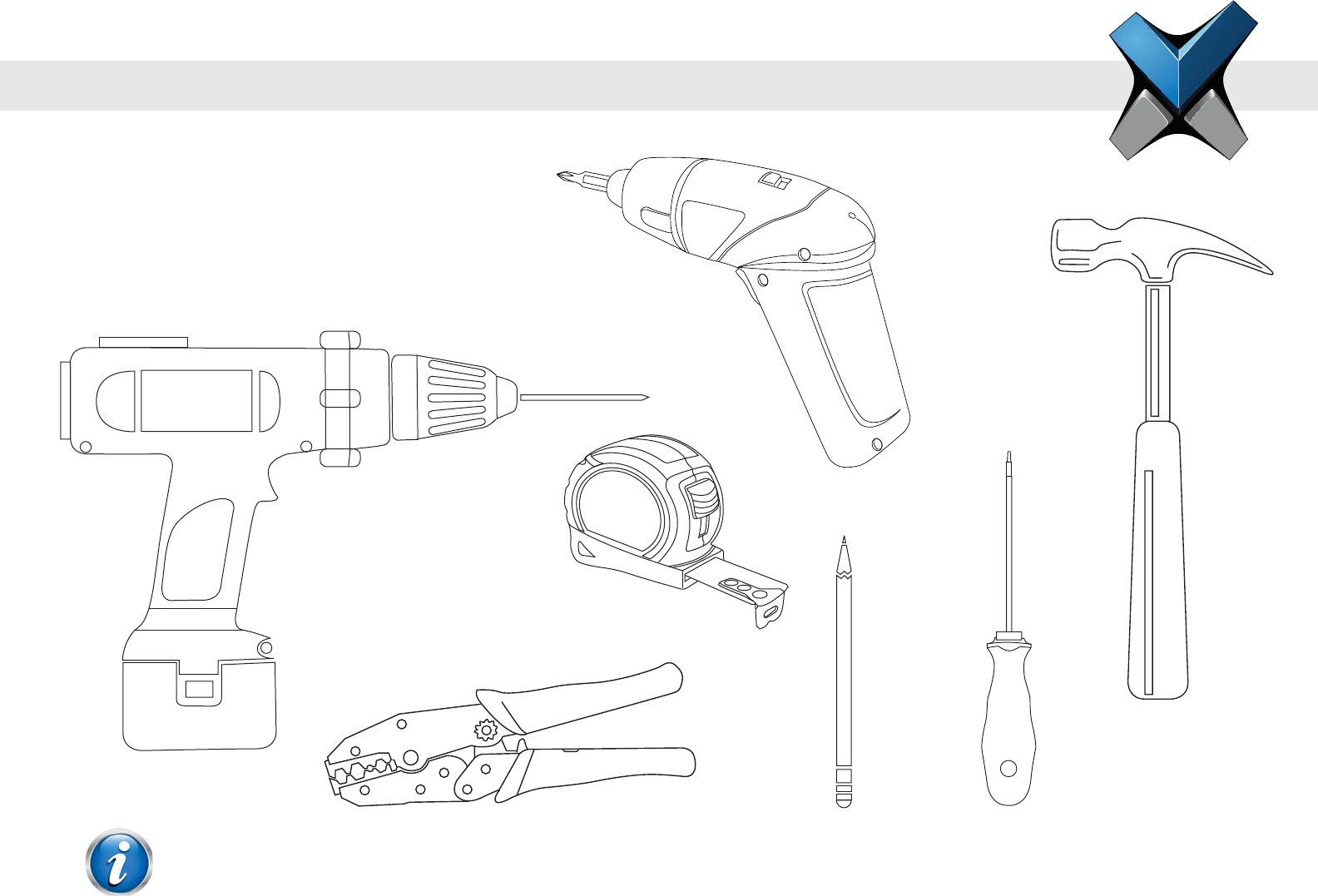
Hardware Tools Required For Installation
Pencil
Hammer*
Power Drill*
Ratchet-style Crimping tool
Installation of any IXM device should be performed by licensed electricians.
*Depending on the mounting surface, the Power Drill and Hammer may not be required.
NOTE
Measuring Tape
Battery powered
Screwdriver
Manual Screwdriver
INVIXIUM
Copyright© 2013
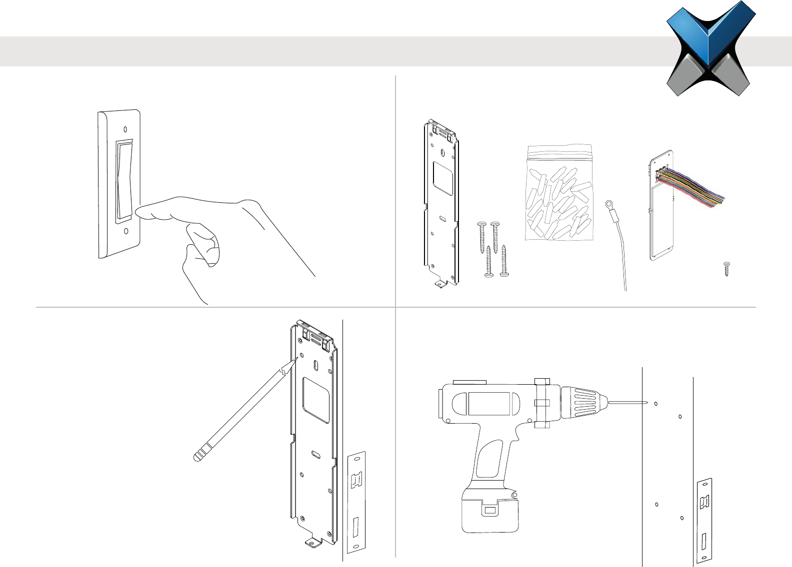
1 Ensure Power is Off
This protects the device being installed.
ON
OFF
2 IXM Install Kit
Remove the following items from the kit:
4 Drill Holes
If required, drill holes where marked and install the appropriate wall
anchors (not included) using the hammer.
3 Mark the Screws Holes
INVIXIUM recommends the
use of the 4 circular holes for
mounting. Refer to diagrams on
page 8, 10 or 12 for actual
dimensions.
Ideal mounting height is 120 -
140 cm from the ground to
the top of the device. But
also be sure to align the
device in case of multiple
installations.
120-140 cms
16
DOLPHIN
DOLPHIN
DOLPHIN
DOLPHIN
DOLPHIN
DOLPHIN
DOLPHIN
DOLPHIN
DOLPHIN
DOLPHIN
DOLPHIN
DOLPHIN
DOLPHIN
DOLPHIN
INVIXIUM
Copyright© 2013
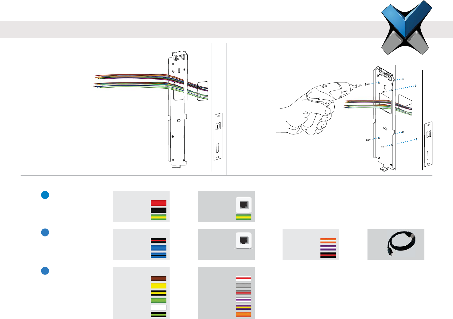
6 Insert Screws
Align the holes of the mounting plate with
the wall anchors and attach the mounting
plate with the screws provided in the IXM
Install Kit. Invixium
recommends the use of
an electric or
battery-powered
screwdriver
for this step.
5 Get Wires
Get access to the installation wires
either from behind the wall or from the
wiring conduit. Feed
wires through the
square hole of the
mounting plate.
7 Identify the Connections:
DC Power
VIN+
VIN-
EGND
PoE
RJ-45
Receptacle
EGND
Power & Grounding
1
Communications RS-485
SGND
RS-485+
RS-485-
Ethernet
RJ-45
Receptacle
USB RS-232
RS-232_RX
RS-232_TX
SGND
Operations ACP
ACP_LED1
ACP_LED2
ACP_LED_GND
WDATA_OUT0
WDATA_OUT1
WGND
DAC
RLY_NC
RLY_COM
RLY_NO
DAC_IN1
DAC_IN2
DAC_OUT
2
3
OR
OR OR OR
OR
Refer to pages 20 & 21 for Power connections,
pages 22-25 for Network or Serial Communication
connections and pages 26 & 27 for Operation
connections.
17
INVIXIUM
Copyright© 2013
DOLPHIN
Earth Ground Wire
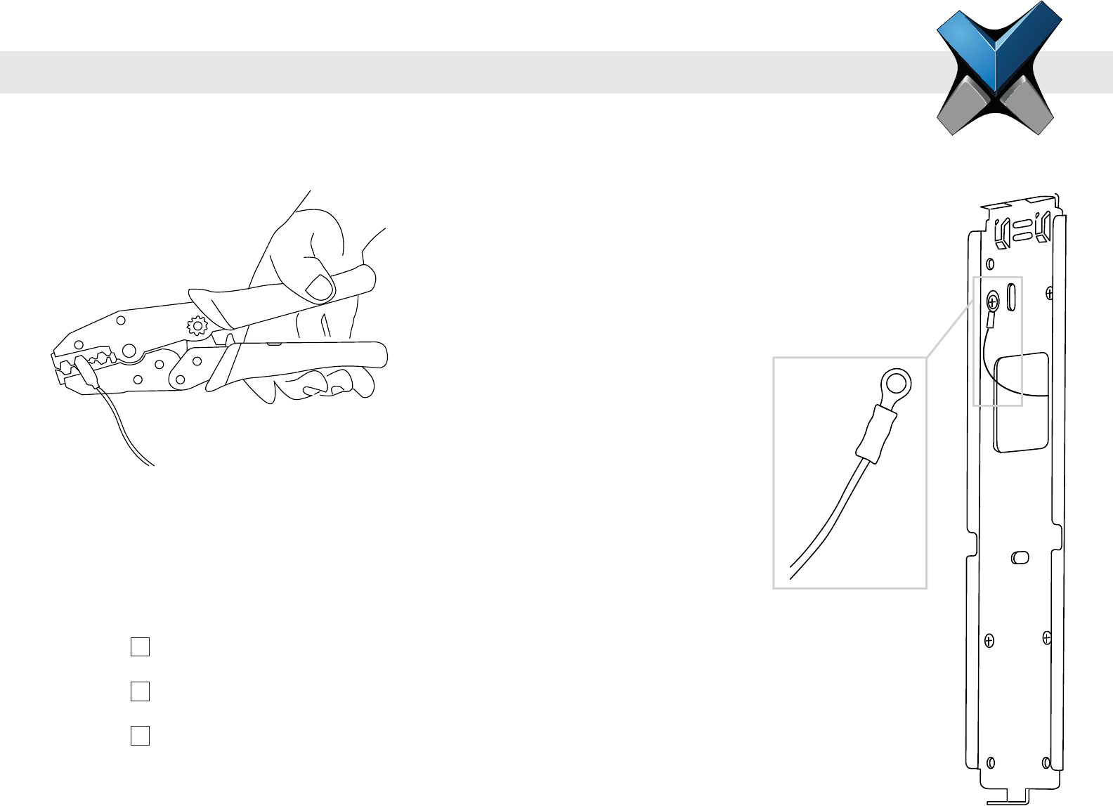
8A Make the Connections
Connect the required wires using the Dolphin® crimps provided in the IXM Install Kit (or any similar
crimps) and a ratchet style crimping tool. Insert the two wires (no stripping required) into the open end of
the crimp and then using the crimping tool, clamp down on the middle of the crimp.
8B Connect Earth Ground
Connect the lug of the Earth Ground wire directly to the front of the mounting plate using one of
the Wall mounting screws. Ensure that the lug is secured tightly as to make the necessary contact
between the device and the mounting plate. Connect the other end of the Earth Ground wire to
the Earth Ground connection of the install site with a crimp.
Ensure all required connections are made to each device in the setup prior to turning on the power.
Checklist: Connections for Power & Grounds (DC or PoE)
Connections for Communications (Ethernet, RS-485 or RS-232)
Connections for Operation (ACP or DAC)
Lug
18
INVIXIUM
Copyright© 2013
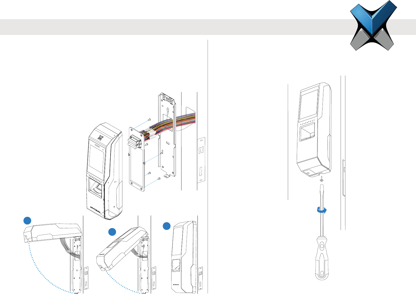
10 Secure the Device
Finally, secure the device on the bottom to
the mounting plate with the Metal Mounting
Plate screw provided in the IXM Install Kit.
9 Attach the Device
Take the IXM device and unscrew the Temporary Back Cover,
keeping the screws handy. Connect the Wired Back Cover to
the back of the device by lining up the connectors. Secure the
Wired Back Cover with the same screws. Next, hang the IXM
device onto the mounting plate as shown in the series of
diagrams below.
1
2
INVIXIUM
3
19
INVIXIUM
Copyright© 2013
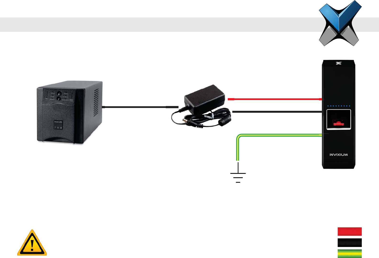
Connections for Power
INVIXIUM recommends:
12-24 VDC regulated power supply
Dedicated Power Supply for each IXM device (minimum 1 A)
Use of a battery back-up or UPS with built-in surge protection
If sharing power supplies, ensure that each device is supplied with minimum 1 A per device
(ie. Powering two devices will require an supply with output current of 2 A)
Bottom Connector Power
VIN+ (1)
VIN- (3)
EGND (5)
Product Warranty is void if improper power (under or over) is supplied to the device.
WARNING
20
IXM MYCRO
DC Power Supply
UPS
EGND
VIN+
VIN-
UPS
INVIXIUM
Copyright© 2013
INVIXIUM recommends:
A centralized Power Sourcing Equipment (PSE) for full PoE deployments (not included)
Use of a battery back-up or UPS with built-in surge protection
Only available on IXM SENSE and IXM TOUCH
Connections for Power Over Ethernet (PoE)
Both IEEE 802.3af power transmission modes (A and B) are supported.
NOTE
21
IXM SENSE
IXM TOUCH
Bottom Connector PoE
TX+ (9)
TX- (11)
RJ45_PIN4 (13)
RX+ (15)
RX- (17)
RJ45_PIN7 (19)
INVIXIUM
Copyright© 2013
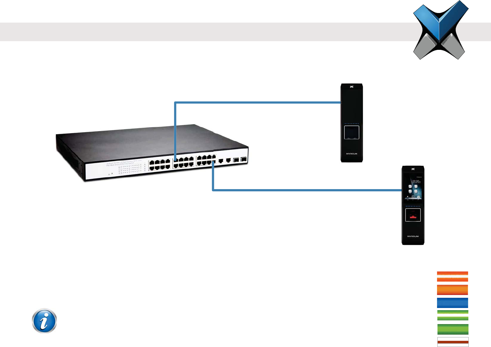
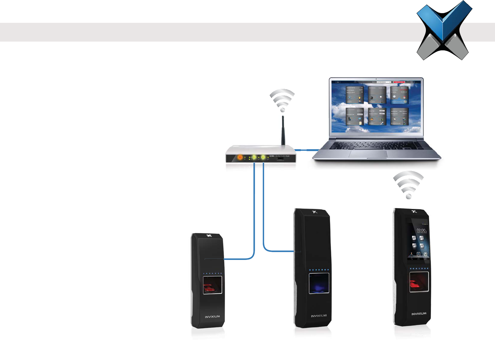
Ethernet and Wi-Fi Communication
Ethernet:
Switch/Router required
CAT 5 cabling or better
WiFi:
Wireless router to LAN/WAN
802.11b/g/n protocol
WEP, WPA and WPA2 encryptions supported
DHCP enabled by default
IXM WEB
Router connected to
LAN/WAN
IXM TOUCHIXM SENSEIXM MYCRO
22
INVIXIUM
Copyright© 2013
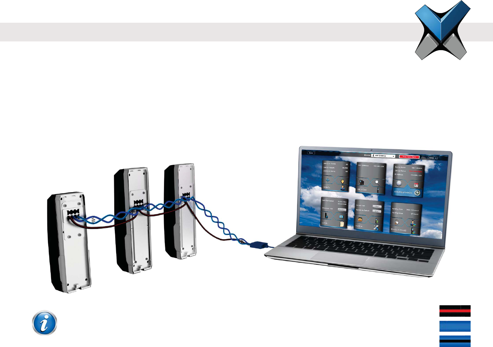
RS-485 Network Communication
INVIXIUM recommends:
Maximum 31 devices in the network
Both RS-485 converter and the last device in the chain should be terminated (not included, refer to NOTE below for
correct Resistor values)
Connect the IXM device to PC via RS-485-to-Serial (RS-232 or USB) Converter
Maximum cable length of 1200 m (4000 ft.) at 9600 bps baud rate
Bottom Connector RS-485
SGND (6)
RS-485+ (8)
RS-485- (10)
B
ottom Connector RS-4
8
SG
ND
(6)
RS-485 to USB
Converter
IXM TOUCH
IXM WEB
IXM SENSE
IXM MYCRO
R
R
R = 120 ohms for Standard RS-485 Cabling
R = 100 ohms for CAT5/6 Cabling
NOTE
23
INVIXIUM
Copyright© 2013
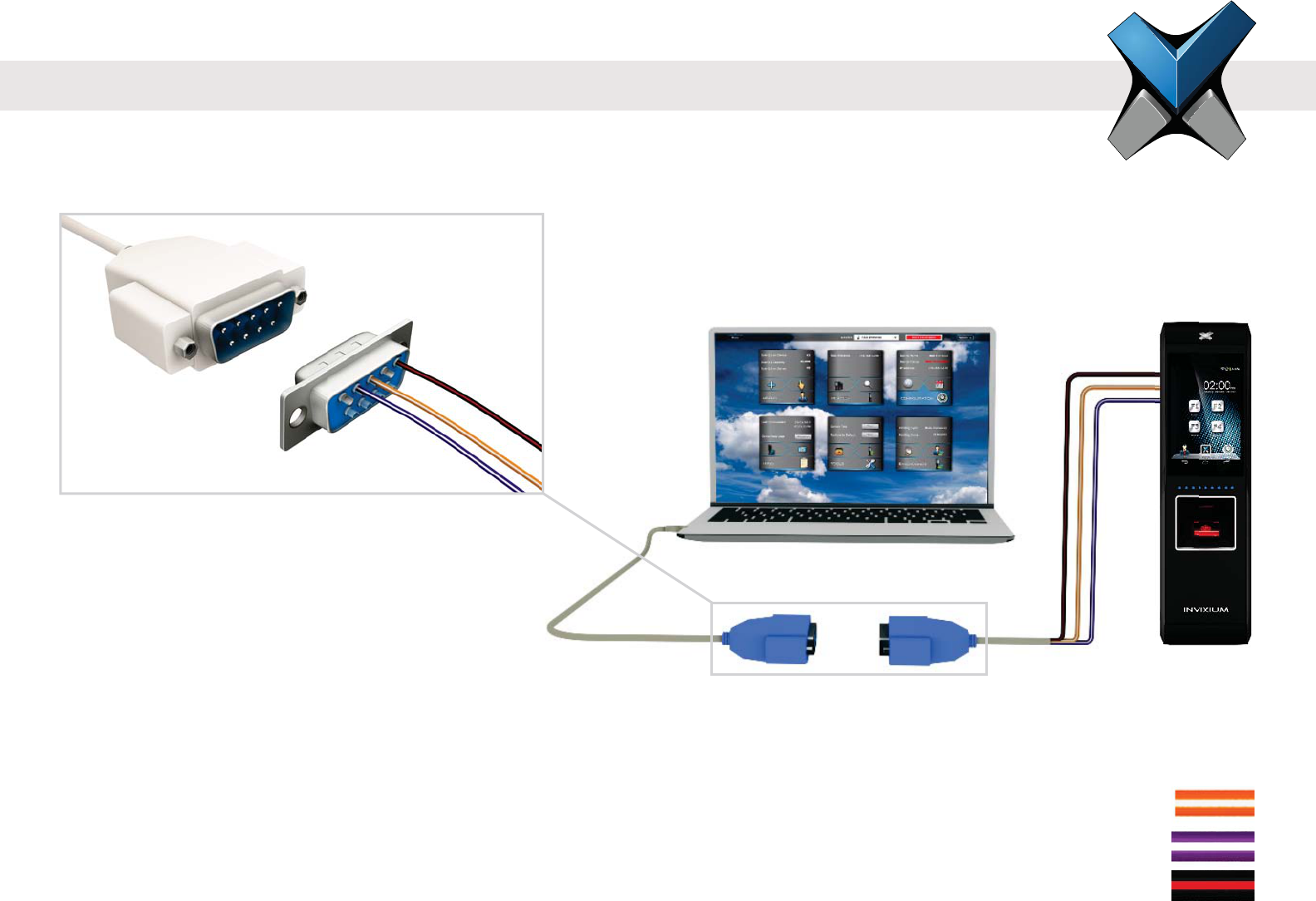
Serial Communication
RS-232:
Connect IXM device directly to the DB9 Serial port of the PC (if available)
DB9 connectors and cables are not included
Bottom Connector RS-232
RS-232_RX (2)
RS-232_TX (4)
SGND (6)
USB-to-Serial Converter
IXM WEB
IXM TOUCH
RS232_RX
RS232_TX
SGND
1 2 3 4 5
24
INVIXIUM
Copyright© 2013
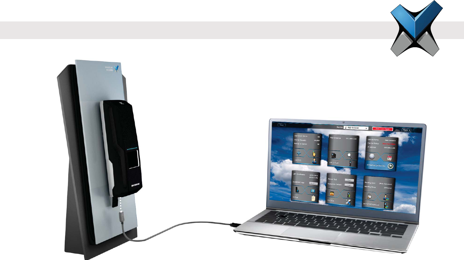
USB:
USB port can also be used to connect to a PC running IXM WEB via Micro USB cable
Driver installation is required and will automatically initiate once the device is connected
Host PC
Micro USB cable
(Provided in IXM
Install Kit)
IXM SENSE
USB Communication
25
INVIXIUM
Copyright© 2013
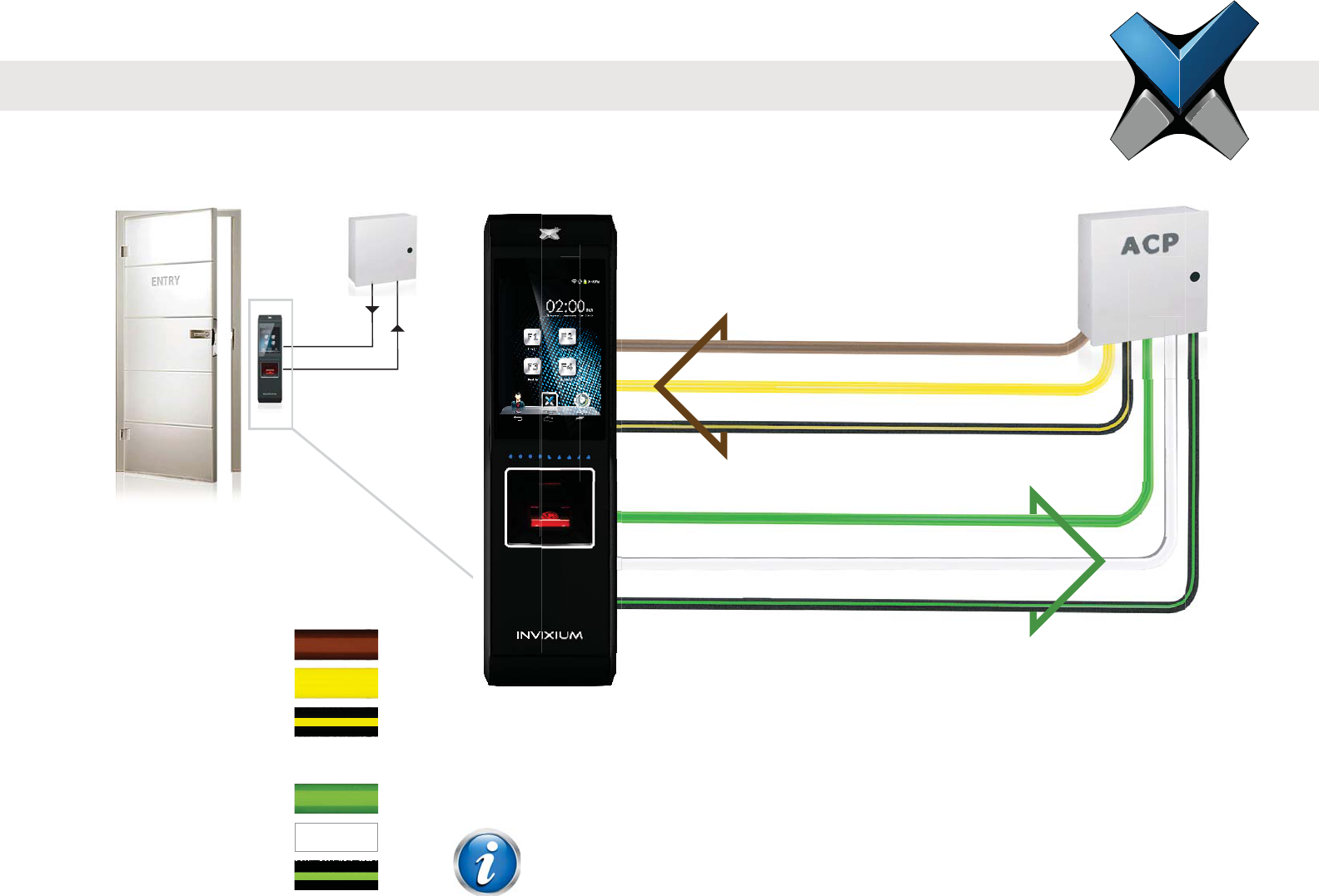
Access Control Panel Connections
ACP:
LED and Wiegand connections available for ACP operation
INVIXIUM recommends the use of Wiegand Output Data 0, 1 and GND connection
Top Connector LED
ACP_LED1 (7)
ACP_LED2 (9)
ACP_LED_GND (11)
Bottom Connector Wiegand
WDATA_OUT0 (16)
WDATA_OUT1 (18)
WGND (20)
3
3ACP_LED1
ACP_LED_GND
WDATA_OUT1
ACP_LED2
WDATA_OUT0
WGND
IXM TOUCH
ACP_LED signals can be used if available on the Access Control Panel.
IXM devices support up to 2 wires + GND for LED status.
NOTE
26
INVIXIUM
Copyright© 2013
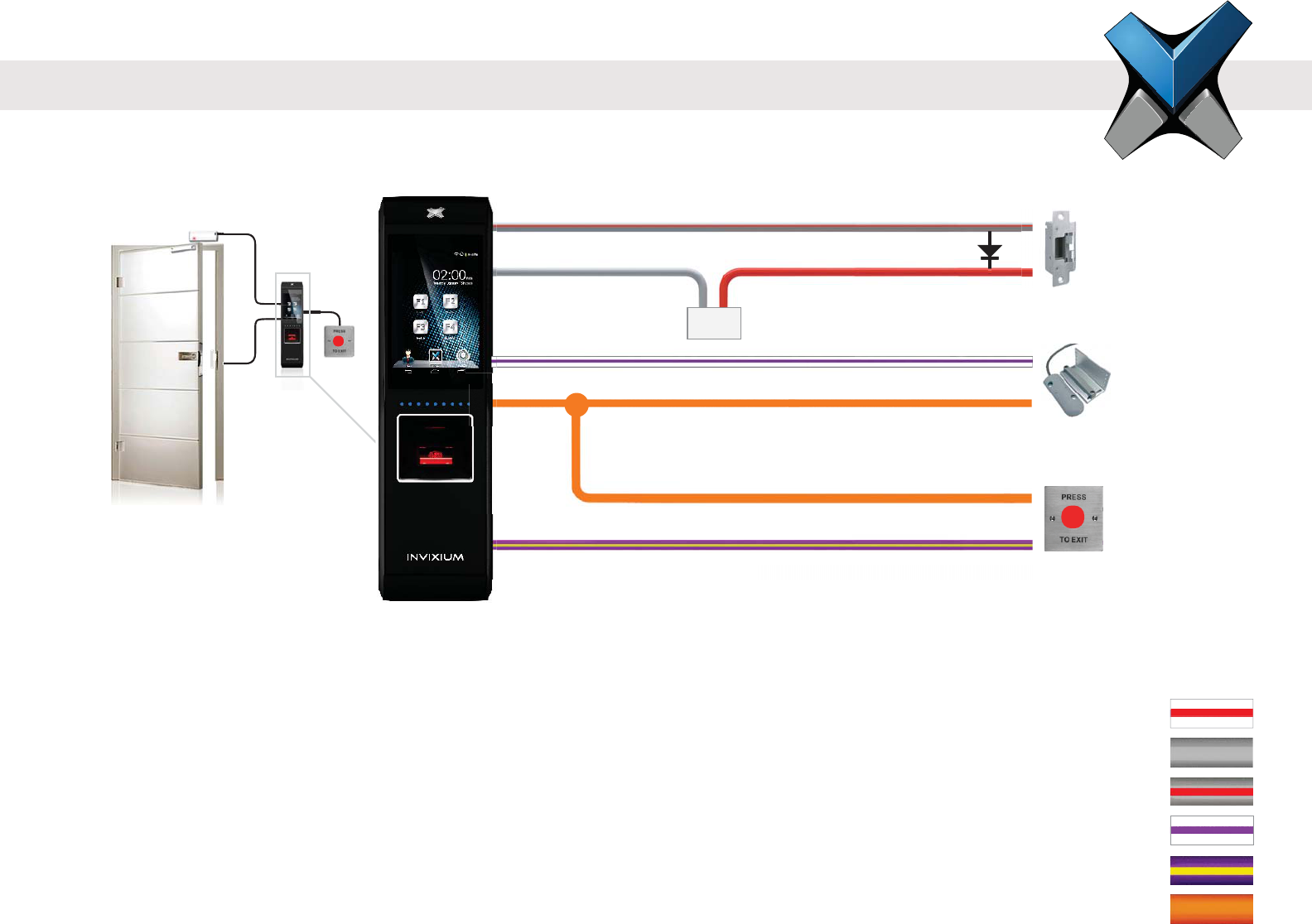
Door Access Control Connections
DAC:
INVIXIUM recommends a separate power supply for Door Strike (not included)
Snubber Diode required for Door Strike (not included)
Example above shows use of RLY_NO, but RLY_NC may be used instead if required by the Door Strike
Internal Relay rated upto max of 1 A @ 30 VDC, external relay required if Door Strike draws
more than 1A
For motion detector instead of Request-to-Exit-button, connect the following signals:
(1) DAC_OUT to the COM and (2) DAC_IN2 to the Relay NO of the motion detector
*Max Relay rating=1 Amp @ 30 VDC
*
Max Re
l
ay rating=1 Amp @ 30 V
DC
+
-
RLY_NO
DAC_IN1
RLY_COM
DAC_OUT
DAC_OUT
DAC_IN2
Snubber Diode
Door Strike Power Supply
Door Strike
Door Contact
Request to exit
IXM TOUCH
27
Top Connector DAC
RLY_NC (1)
RLY_COM (3)
RLY_NO (5)
DAC_IN1 (13)
DAC_IN2 (15)
DAC_OUT (18)
INVIXIUM
Copyright© 2013
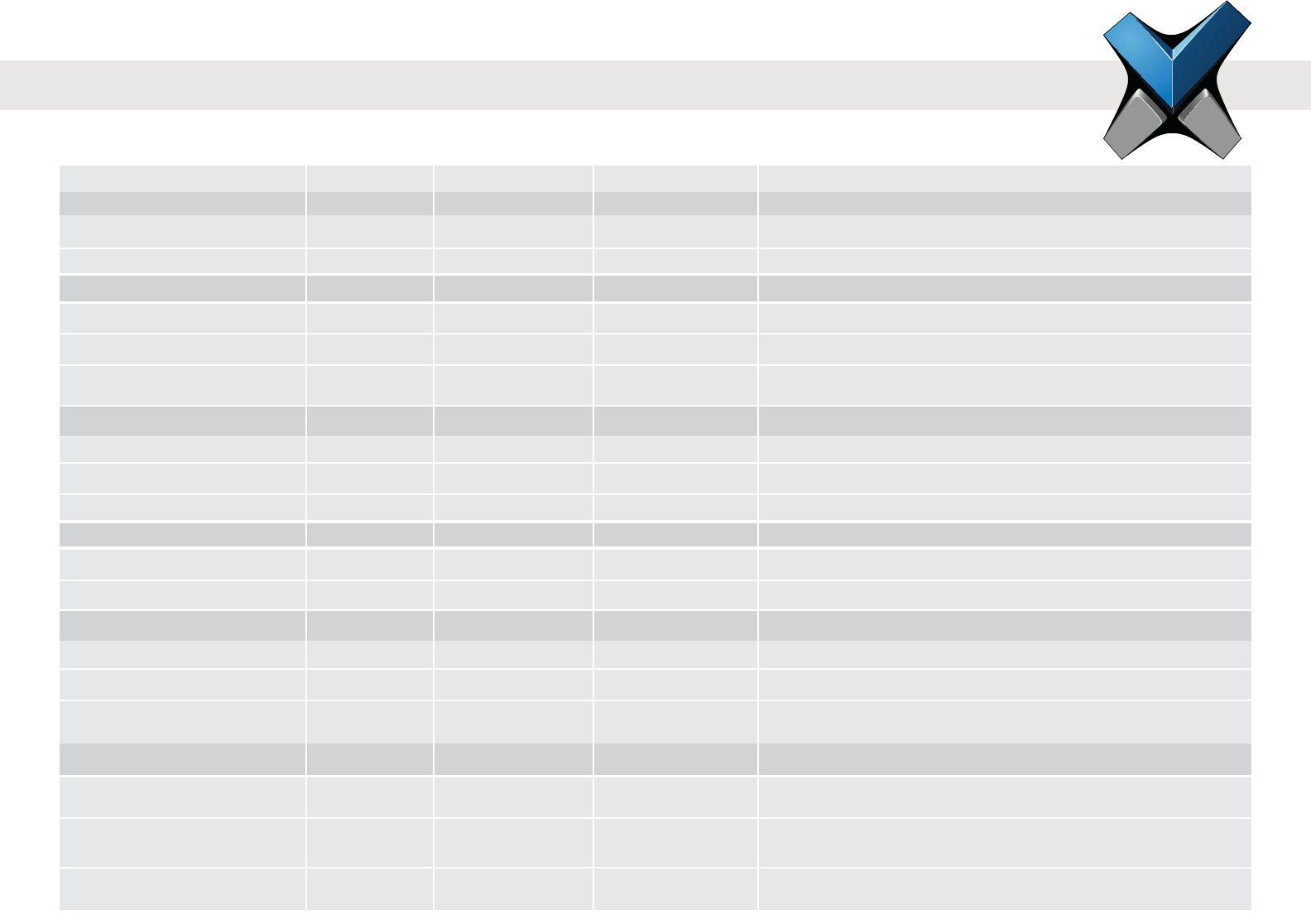
Power
Min. Value Recommended
Voltage (V) 9.6
Current (A)
VIN_H (V)
Specic Purpose Inputs
VIN_L (V)
Wiegand Inputs
Specic Purpose Outputs
Wiegand Outputs
Internal Relay
VIN_H (V)
VIN_L (V)
VOUT_H (V)
VOUT_H (V)
VOUT_L (V)
Current Rating (A)
Switching Power (R)
Switching Voltage (V)
12
1
Max. Value
4
10K
24
1
2
10K
0.8
4.2
0.44
4.5
4.7K
0.8
1
0.3
110
125
30 Watt
30 VA
INVIXIUM recommends using a regulated DC power supply
and SPI3 lines
Wiegand Output is an open drain output.
@IOH = -24mA
@IOL = +24mA
@ 30 VDC
@ 125 VAC
DC
AC
DC
AC
-
-
-
-
-
-
-
-
-
-
-
-
-
-
-
-
-
-
-
-
-
-
-
-
-
-
-
-
-
-
Electrical Information
Additional Comments
VOUT_L (V)

INVIXIUM
Copyright© 2013
PC Workstation:
1 GHz Intel® Pentium® 4 or equivalent
(INVIXIUM recommends 2.0 GHz or higher)
1 GB RAM (INVIXIUM recommends 2 GB RAM or higher)
50 MB Free Hard Disk Space for IXM WEB
850 MB Hard Disk for x86 systems or
2 GB Hard Disk for x64 systems for Microsoft®.NET Version 4.0
500 MB Hard Disk Space for Microsoft®.NET Version 2.0
(Windows® XP & Windows® 2003 R2)
1 GB Hard Disk (INVIXIUM recommends) for SQL Server™ 2008
Express Edition SP1
Available COM or USB port
Ethernet Card (10/100 Mb Ethernet connections)
Monitor capable of displaying at least 1024 x 786 high colour
resolution
Software Installation System Requirements
To successfully install and run Invixium software, the system must meet the following minimum requirements:
One of the following Operating Systems:
Windows® 8 and 7 both 32-Bit and 64-Bit versions
Windows® XP Service Pack 3 or higher
Windows® Server 2012
Windows® 2008 R2
Windows® 2008
Windows® 2003 R2
One of the following Web Browsers (Client):
Internet Explorer® version 8.0 or higher
Google Chrome™ version 26.0 or higher
Mozilla Firefox® version 20.0 or higher
Apple Safari® version 5.1.7 or higher
IXM WEB will install the following:
Microsoft®.NET Framework (version 4.0)
SQL Server™ 2008 Express Edition Service Pack 1
Microsoft® Internet Information Services (version 7.5)
Windows® Installer (version 4.5)
29
INVIXIUM
Copyright© 2013
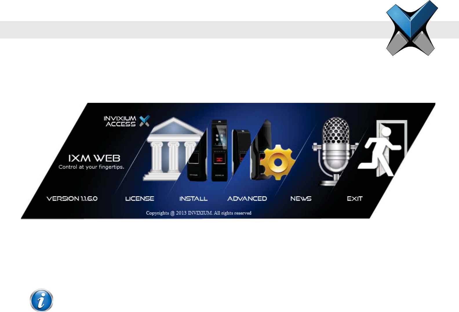
Software Installation Steps
Step 1 Plug the USB drive (found in IXM INSTALL KIT) into an available port on PC.
Step 2 Open the USB drive folder. Run IXMWEBIXM WEB Install Menu will initiate.
Step 3 There are two installation options: INSTALL or ADVANCED. INVIXIUM recommends selecting INSTALL option for rapid
installation.
The ADVANCED process allows for:
entering a different install path
NOTE
A Windows dialog may pop up to provide a warning about installing from an unreliable source.
Click “Yes” to proceed with the install.
30
checkbox for installing SQL Server database

INVIXIUM
Copyright© 2013
Step 4 During the installation process, the status of the install will be shown.
Step 5 When the installation is complete, click EXIT. IXM WEB icon is now on the desktop.
Step 6 Run IXM WEB to launch the application in the default web browser to setup the Database and Admin credentials.
31
INVIXIUM
Copyright© 2013
FCC Information to Users (English)
This device complies with part 15 of the FCC Rules. Operation is subject to the following two conditions:
1. This device may not cause harmful interference
2. This device must accept any interference received, including interference that may cause undesired operation.
This equipment has been tested and found to comply with the limits for a Class B digital device, pursuant
to part 15 of the FCC Rules. These limits are designed to provide reasonable protection against harmful
interference in a residential installation. This equipment generates, uses and can radiate radio frequency
energy and, if not installed and used in accordance with the instructions, may cause harmful interference
to radio communications. However, there is no guarantee that interference will not occur in a particular
installation. If this equipment does cause harmful interference to radio or television reception, which can be
determined by turning the equipment off and on, the user is encouraged to try to correct the interference by
one or more of the following measures:
Reorient or relocate the receiving antenna
Increase the separation between the equipment and receiver
Connect the equipment into an outlet on a circuit different from that to which the receiver is connected
Consult the dealer or an experienced radio/TV technician for help
Informations de la FCC aux Utilisateurs (en Français)
Cet appareil est conforme à la partie 15 des règles de la FCC. Son fonctionnement est soumis aux deux conditions suivantes:
1. Cet appareil ne doit pas provoquer d'interférences nuisibles
2. Cet appareil doit accepter toute interférence reçue, incluant toute interférence pouvant causer un fonctionnement indésirable
Notice
32
INVIXIUM
Copyright© 2013
CE Information to Users (English)
All INVIXIUM devices have the CE mark for conformance with EMC Directive 89/336/EEC, and Low Voltage Safety Directive 73/23/EEC.
Device with RFID components are compliant with R&TTE Directive 1999/5/EC, and are Class 1 Devices.
Informations de la CE aux Utilisateurs (en Français)
Tous les dispositifs de INVIXIUM ont le marquage CE de conformité à la directive CEM 89/336/CEE et basse tension de sécurité Directive
73/23/CEE. Les appareils avec composants RFID sont conformes aux Directive R & TTE 1999/5/CE. et sont des appareils de classe 1.
Notication
Cet équipement a été testé et s'est avéré conforme aux limites pour un appareil numérique de Classe B,
conformément à la partie 15 des règles de la FCC. Ces limites sont conçues pour fournir une protection
raisonnable contre les interférences nuisibles dans une installation résidentielle. Cet équipement génère,
utilise et peut émettre des fréquences radio et, s'il n'est pas installé et utilisé conformément aux instructions,
il peut causer des interférences nuisibles pour les communications radio. Cependant, il n'existe aucune
garantie que des interférences ne se produiront pas dans une installation particulière. Si cet équipement
provoque des interférences nuisibles à la réception radio ou de télévision, ce qui peut être déterminé en
l'éteignant et rallumant, l'utilisateur est encouragé à essayer de corriger l'interférence par une ou plusieurs
des mesures suivantes:
Réorienter ou déplacer l'antenne de reception
Augmentez la distance entre l'équipement et le récepteur
Connecter l'équipement à une sortie sur un circuit différent de celui sur lequel le récepteur est branché
Pour obtenir de l’aide, consulter le revendeur ou un technicien radio / TV expérimenté
33
INVIXIUM
Copyright© 2013
Industry Canada Information to Users (English)
This device complies with Industry Canada license-exempt RSS standard(s). Operation is subject to the following two conditions:
1. This device may not cause interference
2. This device must accept any interference, including interference that may cause undesired operation of the device
Industrie Canada Information pour les Utilisateurs (en Français)
Cet appareil est conforme avec Industrie Canada exempts de licence standard RSS (s). Son fonctionnement est soumis aux deux conditions
suivantes:
1. Cet appareil ne doit pas provoquer d'interférences
2. Cet appareil doit accepter toute interférence, y compris celles pouvant causer un mauvais fonctionnement de l'appareil
Warning to Users (English)
Avertissement aux Utilisateurs (en Français)
Warning
INVIXIUM could void the user's authority to operate the
equipment.
Avertissement
INVIXIUM pourraient annuler l'autorité
de l'utilisateur à utiliser l'équipement.
34

invixium.com
For Technical or Customer Support issues,
please contact your Local Authorized Reseller.
For all other inquiries, please contact us at
Experience@invixium.com
For detailed information, please visit the links below:
INSTALLATION GUIDE
www.invixium.com/installation
INGUIDE (online copy)
www.invixium.com/inguide
USER'S GUIDE
www.invixium.com/userguide
invixium
access
Enjoy the Experience.
Some features may vary based on device models.
Copyright © 2013, INVIXIUM. All rights reserved.
P/N XAD-00E-001-01G
© 2013 Google Inc. All rights reserved. ChromeTM browser is a trademark of Google Inc.
Firefox logo® is a registered trademark of the Mozilla Foundation.
Windows® and Internet Explorer® are trademarks of the Microsoft group of companies.
Safari® is a trademark of Apple Inc.
35