Iolan Systems LA-WIWPROXKEYM Security Badge Reader User Manual ISIBR
Iolan Systems Inc. Security Badge Reader ISIBR
Contents
- 1. ISI Technical Brochure
- 2. Badge Reader info
Badge Reader info
September 21, 1998 www.iolan.com Page: 1
Iolan Systems, Inc.
1200 Barton Hills Dr. Suite 233
Austin, Texas 78704
Tel: (512) 443-4369
Fax: (512) 443-3615
SALES SPECIFICATIONS LA-WIW-PROXKEY-M
Gerard Verkaart
President
Email: gverkaart@austintx.com

LA WIW Proxkey M
ISIBR.doc www.iolan.com Page: 2
1. Contents
1. CONTENTS..........................................................................................................................................................2
2. PURPOSE OF THIS DOCUMENT....................................................................................................................3
3. DESCRIPTION OF THE READER...................................................................................................................3
4. DATA AND RELATION WITH TC NETWORK............................................................................................3
5. TECHNICAL DATA............................................................................................................................................4
6. PARAMETERS OF THE MODULE .................................................................................................................5
7. DIMENSIONS OF THE MODULE: ..................................................................................................................5
8. CONNECTING.....................................................................................................................................................6
9. THE WIEGAND INTERFACE ..........................................................................................................................7
10. THE LED INTERFACE..................................................................................................................................7
11. WIEGAND PROTOCOL ................................................................................................................................8
12. CHARACTER COMPOSITION ....................................................................................................................8
13. METHOD OF SENDING AND TIMING ......................................................................................................9
LA WIW Proxkey M
ISIBR.doc www.iolan.com Page: 3
2. Purpose of this document
This document gives a full explanation of the possibilities of the LA-WIW-PROXKEY-M. This information
can be used, for example, in sales documentation.
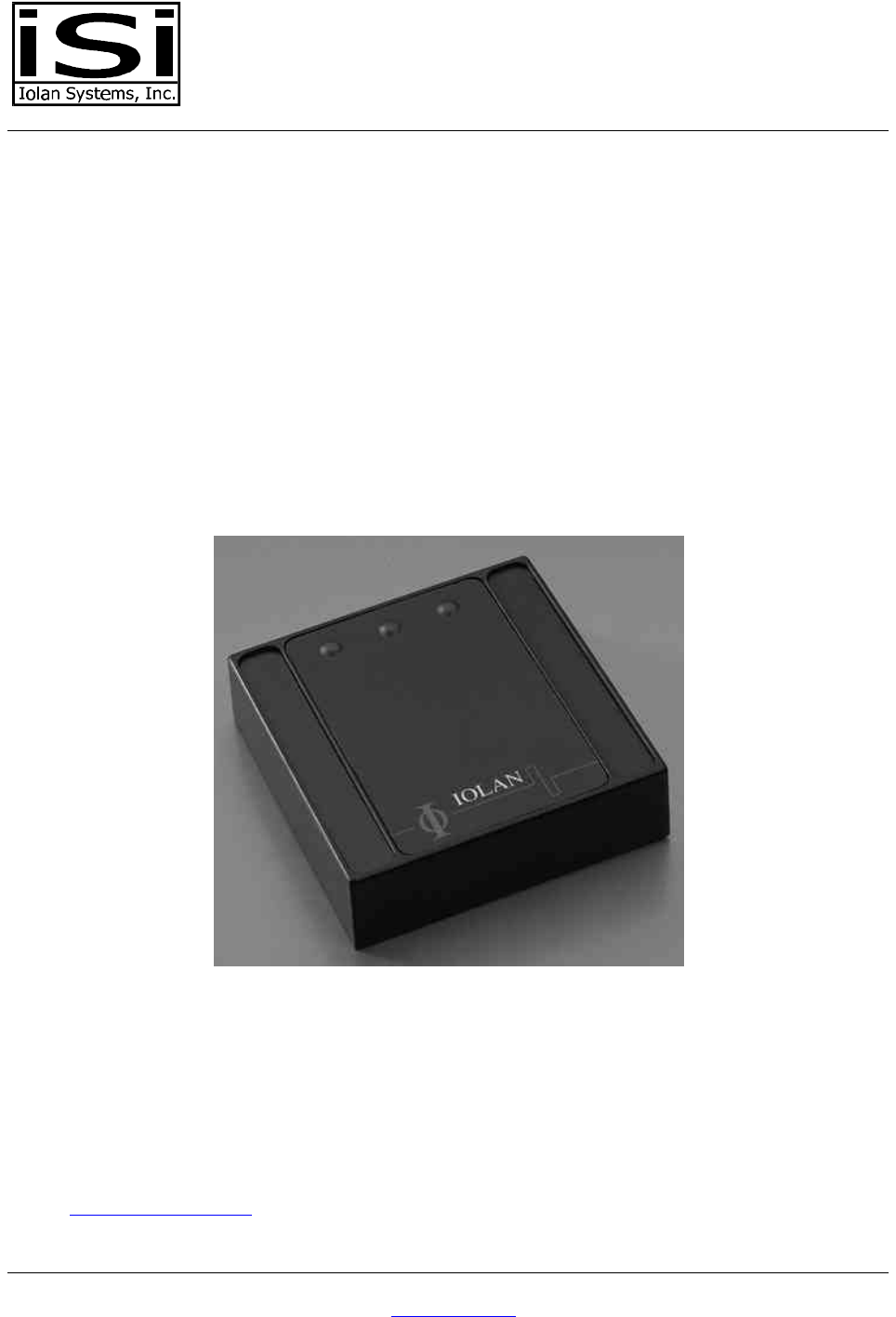
3. Description of the reader
The LA-WIW-PROXKEY-M is a ‘wallmount-module,’ a reader for MIFARE® tags. The module is designed
for identification purposes. It uses a Wiegand data-interface to read a card number, or any other kind of
data, and to send it to the connecting unit. There are three indicators: red, green and yellow. The yellow
lamp blinks when the card is successfully read. A buzzer is available to give signals as programmed
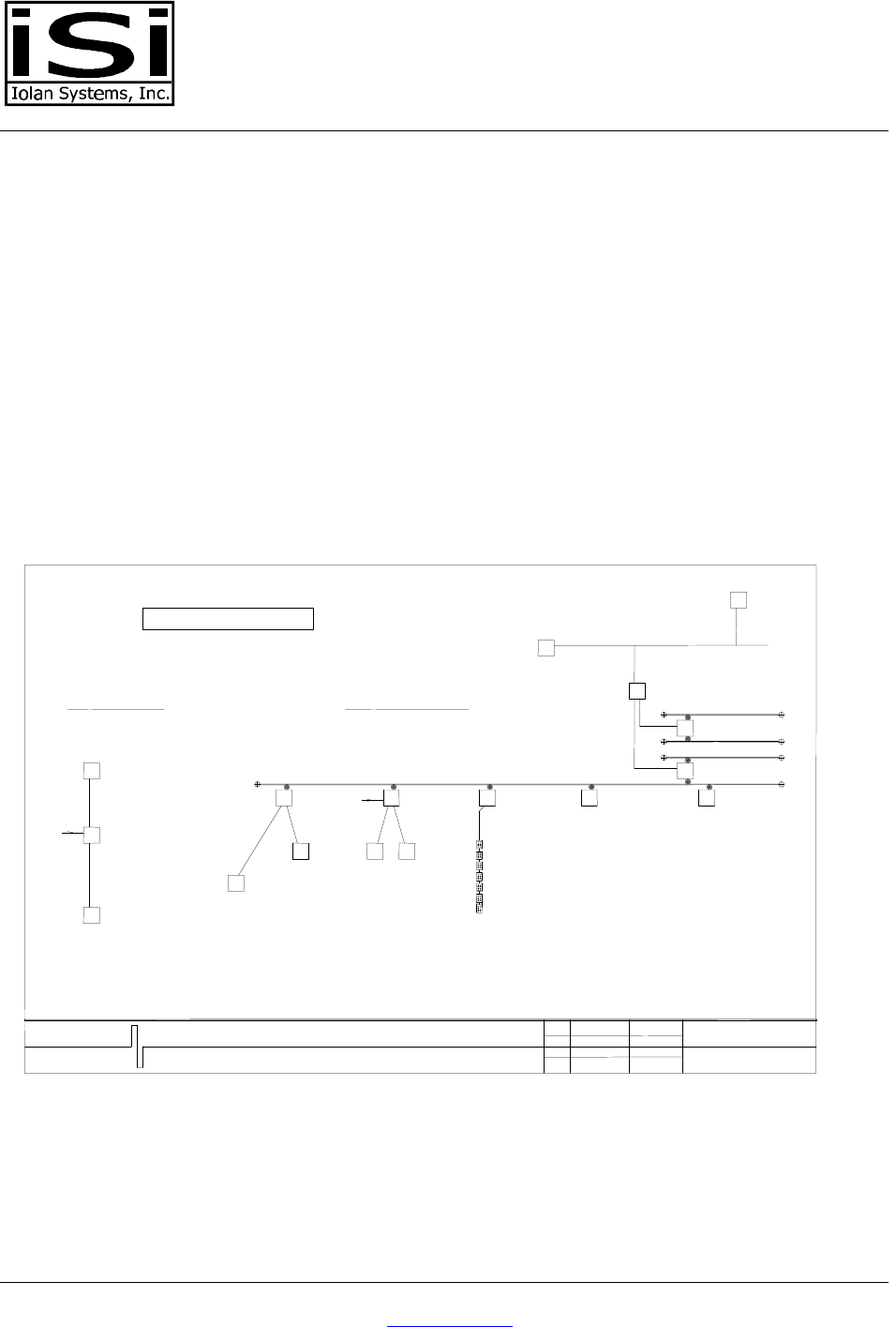
4. Data and Relation with TC Network
The reader can be connected to a network as shown in this scheme:
PC MET
IOLAN_TC
BEHEER
NETWORKITEM :
LA-WIW-PROXKEY-B
SERVER
NETWERK
MET DATABASE PC MET
IOLAN_TC
PC-LAN
SPANT 3
SPANT 4
LA-TCR-RSOMZ-B
SYSTEEM MET MEERDERE MODULEN
KANAALNUMMERS DIENEN ALS
VOORBEELD
EENVOUDIGSTE OPSTELLING
RS232-KABEL
PC MET
IOLAN_TC
LA-TCB-2WI-2I-2R
K8
LA-TCK-2WI-4I-2Y
K9220Vac
LA-TCB-PANEL
K10
LA-TCX-DISPLAY
K11
LA-TCR-RSOMZ-B
LA-TCB-8AN
SPANT 1
SPANT 2
K12
ANALOGE INPUTSDISPLAY MODULE
LA-CHP-8A-8S-H
LA-CHP-8A-8S-V
LA-CHP-8A-8S-R2X
LA-WIW-PROXKEY-B
LA-WIW-PROXKEY-B
LA-TCK-2WI-4I-2Y
&
LA-TCI-RSOMZ-A
220Vac
LA-WIW-PROXKEY-B
LA-WIX-PROXKEY-M
LA-CHR-8I-8Y
LA-CHR-16I-16Q
LA-CHP-8A-8S-G
DIGITALE INPUT EN OUTPUT
IOLAN
GEBOUWAUTOMATISERING
PROJECTNAAM
ONDERWERP
:
:
STANDAARDISERING IOLAN NETWERK
LA-WIW-PROXKEY-B DEEL : NETWERKSYMBOLIEK
GET.
GEW.
GEW.
GEW.
E.LEMM PROJECTNR.
TEKENING NR.
13-10-1997 R086
E003
LA WIW Proxkey M
ISIBR.doc www.iolan.com Page: 4
5. Technical data
Input
Input • 5..0 Volt. The power input is included in the 6 pins connector. In
cooperation with IOLAN-modules the power is supplied.
• 50..80mA.
Technical data
WI interface • 6 pins connector with:
• 2x power supply
• 2x lamp switcher
• 2x data. Wiegand ‘clock-data’
• Data structure according to ISO 7811/2-1986 TRACK 2
Reading distance • 20mm typical, min 10mm max 30mm met transponder types : MF1-
S50, MF1-P60 en MF1-L10
Operating frequency • 13,56mhz.
Data-transport transmitting
speed • 106kBd
Security • Data encrypted, protected against recording and ‘replay-attack’.
Possibilities
Transponders • Can read from MIFARE® card types 1, 2, and 3.
• Reader can hold one key (A or B) and one read location for
transponder-identification.
• Flexible transponder-code length.
Indicators • Yellow LED-lamp and buzzer for successful reading action
• Red LED-lamp and green LED-lamp for logistic matters. E.g.: red: no
access; green: access allowed.
Mechanical aspects
Material housing • Typical W-housing
• Black plastic housing, ABS plastic house.
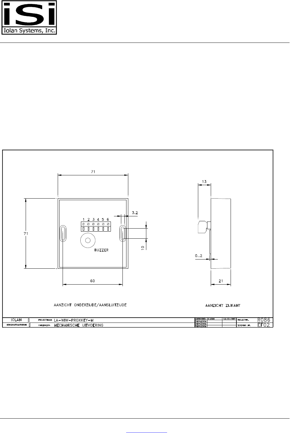
• Dimensions (without connectors; HxBxL mm ) 21x71x71mm. See
drawing R086EF02.
Connection to wall • 2x 3mm opening on 60mm distance. See drawing R086EF02.
Cable connectors • Max. diameter 1.5 mm2
• Connectors 1x6 pins
Protection • When connector-protected IP66.
Temperature • Stock -10..70 o Celsius
• Operating temp 0..50 o Celsius
Installation
Connectors • 6 pins. Thus maximum of 6 connecting wires
Mounting place • When mounting, outside connector must be protected with lacquer, or
the edges must be made watertight.
Ordering information
Type LA WIW Proxkey M
Order number LA 0110 01
LA WIW Proxkey M
ISIBR.doc www.iolan.com Page: 5
6. Parameters of the module
There are no switches on the module; however, according to the MIFARE protocol the readers must be
personalized. There is a procedure available which accomplishes this.
During this personalization-procedure, the key and pointers are downloaded. The key is necessary to gain
access to an application on the transponder. The pointers determine where the information is located.
The reader is constructed in such a way that downloaded keys can never be read from the reader; reading
from the reader is physically impossible; encryption also negates this possibility.
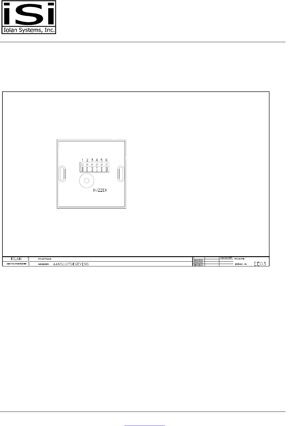
7. Dimensions of the module:
LA WIW Proxkey M
ISIBR.doc www.iolan.com Page: 6
8. Connecting
1 : - Power
2 : Data 2 Clock
3 : Data 1 Data
4 : Switch Green LED
5 : Switch Red LED
6 : + Power
LA WIW Proxkey M
ISIBR.doc www.iolan.com Page: 7
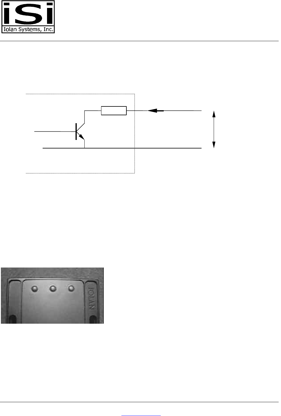
9. The Wiegand Interface
The data interface is a ‘clock-data’ interface. The following scheme shows the hardware of the lines:
• Connector 1, the negative is the reference for the data lines.
• The circuit is similar for clock and data.
• Maximum current through the transistor is 30mA
• The maximum open power is 10 volt. For ESD protection a zenerdiode (12V) is applied parallel over
the emitter en collector.
• There is no pull-up resistance.
10. The LED interface
Two LED’s are externally controlled, the red and the green LED. The yellow LED lights up when a card is
being read.
Red yellow green
The controller can steer the LED’s. Typical use is showing: red = no access, green = access. In case of
using IOLAN modules the controller would be of type LA-TCK-2WI-4I-2Y.
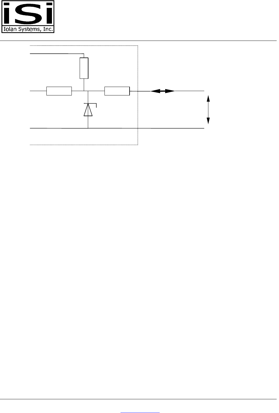
The hardware from the two connections is shown in the next scheme:
330ohm
max 10v
max 30mA
conn. 1
conn. 2/3
LA WIW Proxkey M
ISIBR.doc www.iolan.com Page: 8
The circuits for the green and red LED are similar. The maximum current is ±30mA. Typical use is pulling
the dataline to 0 volt.
11. Wiegand protocol
This version of the IOLAN mifare readers sends out data according to the Wiegand protocol. Sending a
string of digits with a maximum length of 16 is possible.
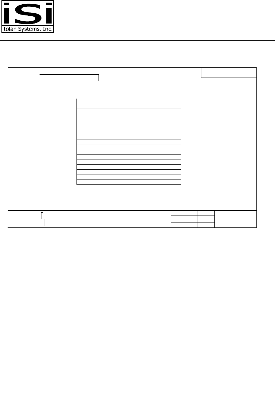
12. Character composition
Immediately after reading a card the reader sends out a string. This string is composed according to ISO
1711/2 track 2:
330ohm max 30mA
Conn. 1
Conn. 4/5
330ohm
4,7kohm
+5v
Uon < 1,5v
Uoff >3,5v
5,1v
LA WIW Proxkey M
ISIBR.doc www.iolan.com Page: 9
CONFIDENTIAL
CHARACTER DEFINITIONITEM :
*ALL CHARACTERS ACCORDING TO ISO 7811/2-1986 TRACK 2
*LIST : CHARACTER
TEXT IN DRAWINGS DISCRIPTION
BITSTREAM
INCLUDING PARITY*
LSB
*
MSB PARITY
1
1
0
0
0
0
0
0
0
0
0
0
0
0
0
0
11
11
1
2
3
DIGIT
DIGIT
DIGIT
0DIGIT
0
1
2
3
4
5
6
7
4
5
6
7
DIGIT
DIGIT
DIGIT
DIGIT
0
0
0
0
0
0
0
0
1
1
1
111
111
1
0
0
1
0
0
0
0
0
0
0
0
0
0
0
11
11
1
1
1
1
START SENTINEL
UNUSED CHARACTER
8
9
DIGIT
DIGIT
8
9
START
UNUSED
*FIELD IS THE ABREVIATION
FOR 'FIELD SEPARATOR'
STOP
FIELD
UNUSED
UNUSED
END SENTINEL
FIELD SEPARATOR
UNUSED CHARACTER
UNUSED CHARACTER 0
0
0
0
1
1
1
111
11
1
1
1
1
1
1
0
0
00000000000000000
EDGE
<STOP><LRC>
11111 01101
<FIELD> <"3">
10110 11001
<"1"> <"2">
01000
<START>
11010 10000
TWO FIELDS : FIELD 2 = "3"
FIELD 1 = "12"
:
EDGE
MESSAGE IS :
*EXAMPLE
00000000000000000
IOLAN
GEBOUWAUTOMATISERING
PROJECTNAAM
ONDERWERP
:
:
STANDAARDISERING IOLAN NETWERK
LA-IOB-PROXKEY
START SENTINEL
DEEL : MAGSTRIPE INTERFACE DATA
CHARACTER DEFINITION
FIELD SEPARATOR
GET.
GEW.
GEW.
GEW.
E.LEMM
END SENTINEL
PROJECTNR.
TEKENING NR.
28-08-1995 S041
E102
The string forwarded by the LA-WIW-PROXKEY-M is default:
(edge) <START> <D0> <D1> <D2> <D3> <D4> <D5> <D6> <D7> <D8> <D9> <END><LRC> (edge)
• The length of the string is defined in the EEPROM and is variable. Standard the length is set to 10
digits.
• The LRC is the XOR of all data characters.
• The ‘edge’ is 2 characters long.
• There is no ‘Card-load’ signal.
• D0 ..D9 is the card identification - number.
13. Method of sending and timing
The to be transmitted data is split up into characters and they are send out one by one Each character
gets its own paritybit. The string as a whole gets an extra parity-character. The character structure is
explained later in this document.
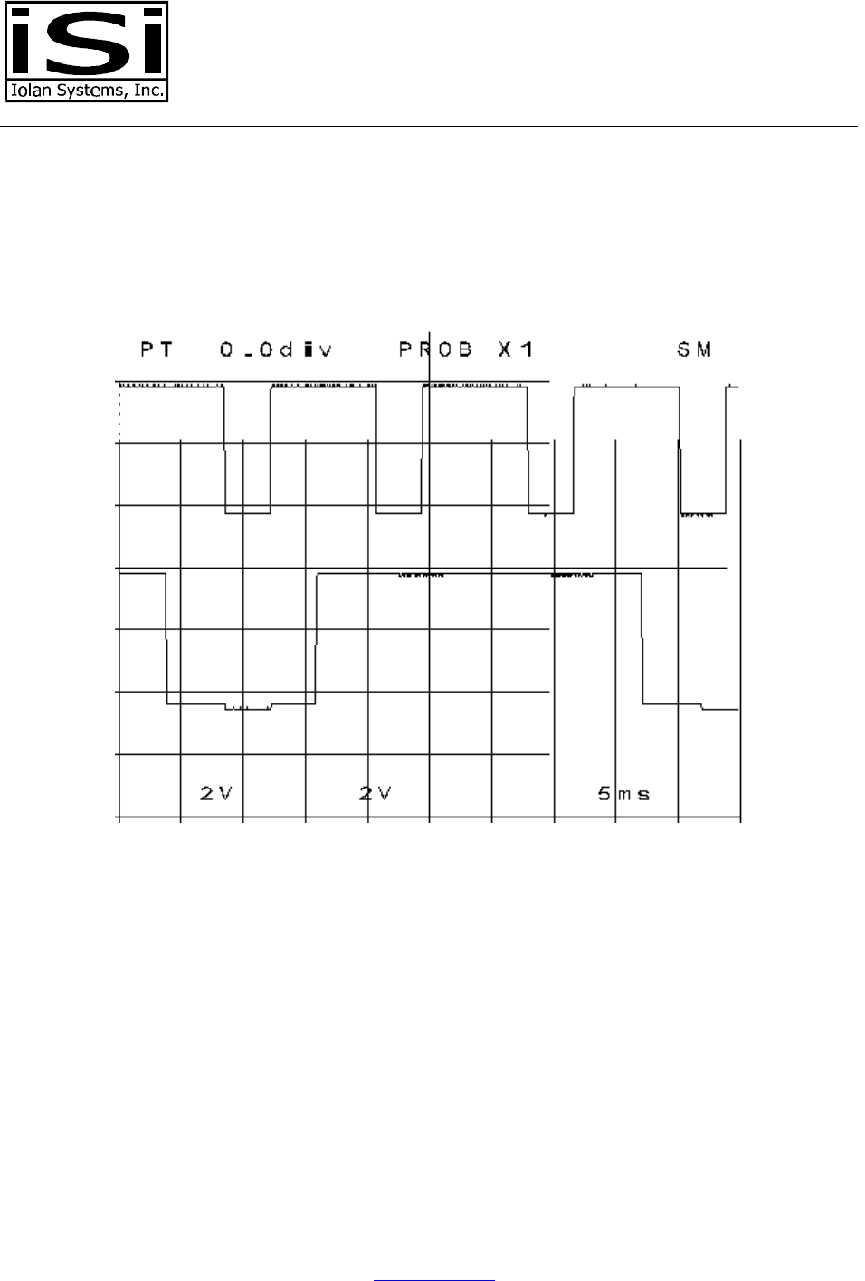
A character consists of 5 bits. 4 databits and 1 paritybit. These are transmitted 1 by 1:
LA WIW Proxkey M
ISIBR.doc www.iolan.com Page: 10
1. Dataline setup
2. clockline goes low.
3. clockline goes up
This gives the following pattern:
file:R086EE01.BMP
• The upper signal line is the clockline. (connector 2)
• The lower signal line is the dataline. (connector 3)
• The setuptime for data 3..5 mS.
• The clock low period is 3..5 mS
• The timelap the data remains up after going up of the clock is 3mS
LA WIW Proxkey M
ISIBR.doc www.iolan.com Page: 11
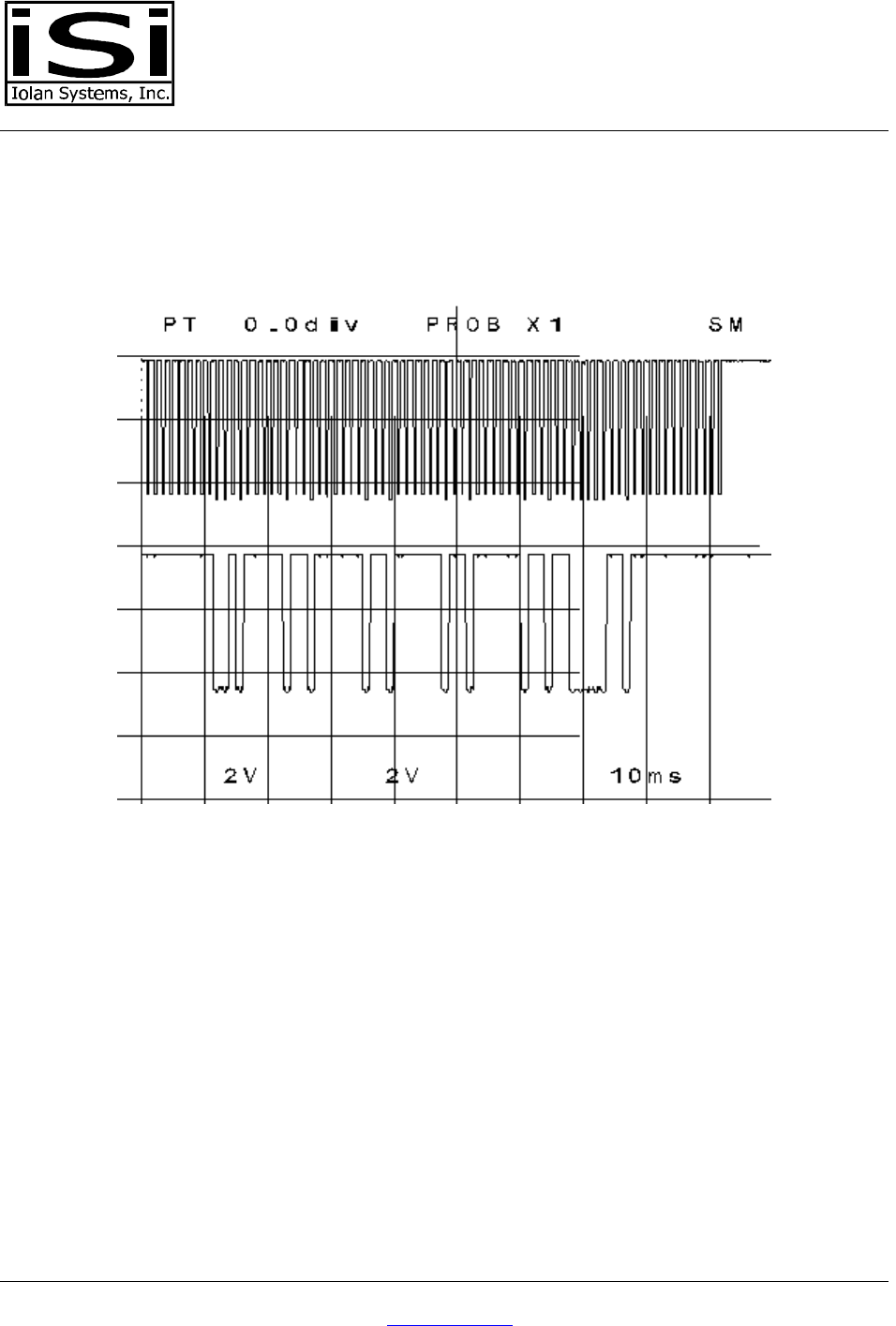
A whole string of 10 characters would look like this:
file:R086EE02.BMP
In this case card number 0404040400 is send.
• The upper signal line is the clockline. (connector 2)
• The lower signal line is the data line. (connector 3)