Iridium Satellite 9602 Iridium Satellite Transceiver Module 9602 User Manual manual
Iridium Satellite LLC Iridium Satellite Transceiver Module 9602 manual
UserManual.wiki
>
Iridium Satellite
>
9602 User Manual
>
manual
Contents
1.
manual
2.
Manual
3.
User Manual
manual
Navigation menu
Upload a User Manual
Namespaces
Wiki Guide
HTML
PDF
Info
Views
User Manual
Discussion / Help
Navigation
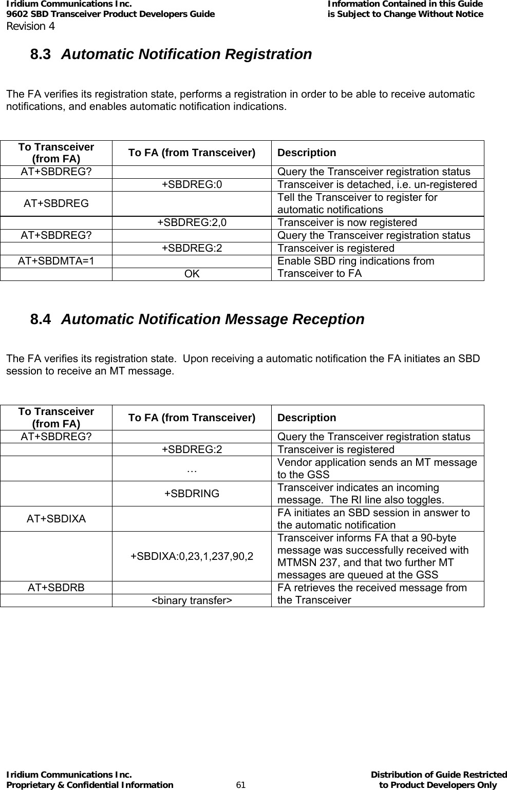
![>>>>>>>>>>>>>DRAFT COPY ONLY<<<<<<<<<<< RELEASE RESTRICTED TO PRODUCT DEVELOPERS ONLY 9602 SBD Product Developer’s Guide Iridium Communications Inc. Proprietary & Confidential Information Iridium Communications Inc. 6707 Democracy Blvd., Suite 300 Bethesda, MD 20817 USA www.iridium.com Toll Free: +1.866.947.4348 [US Only] International +1.480.752.5155 email: info@iridium.com](https://usermanual.wiki/Iridium-Satellite/9602.manual/User-Guide-1265166-Page-1.png)
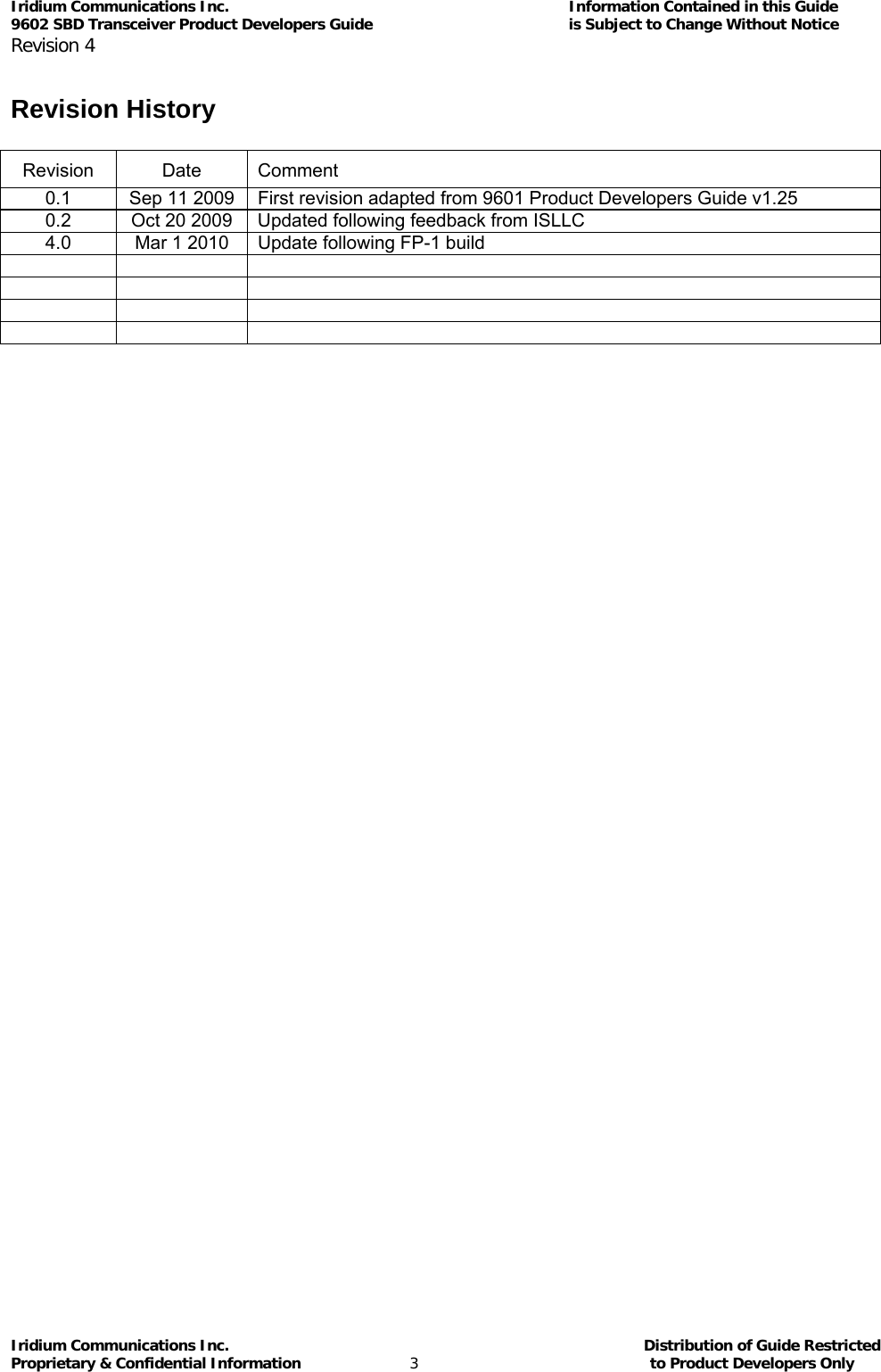
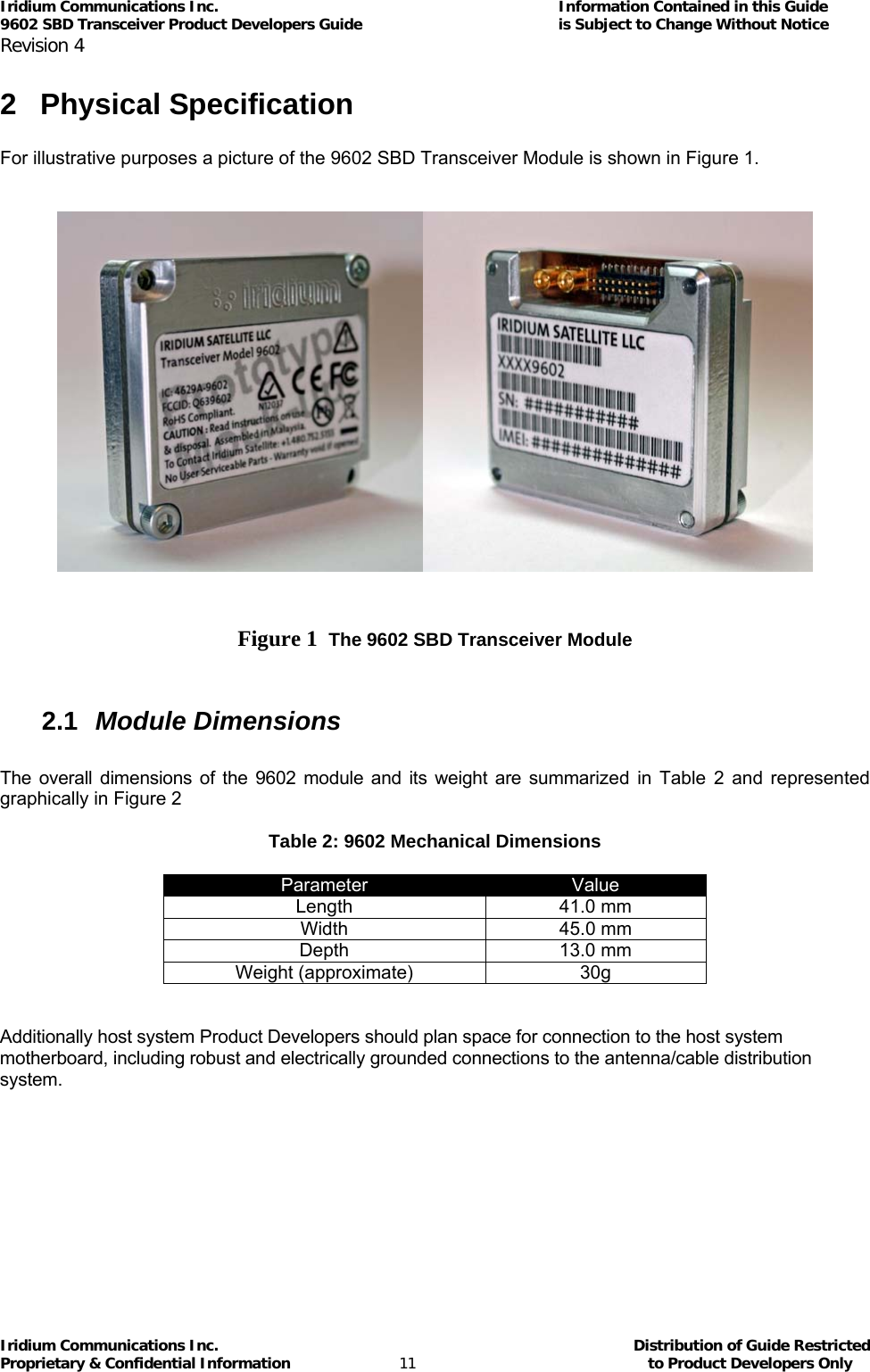
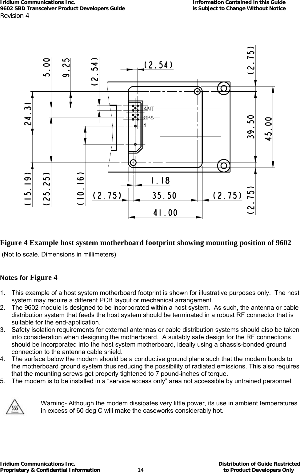
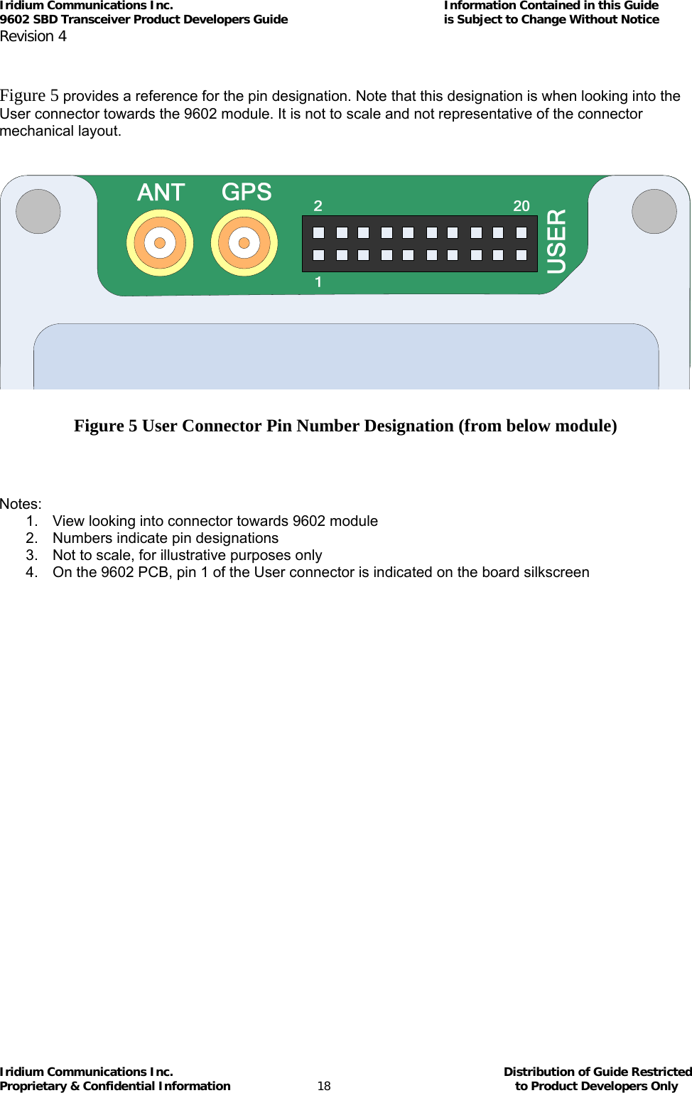
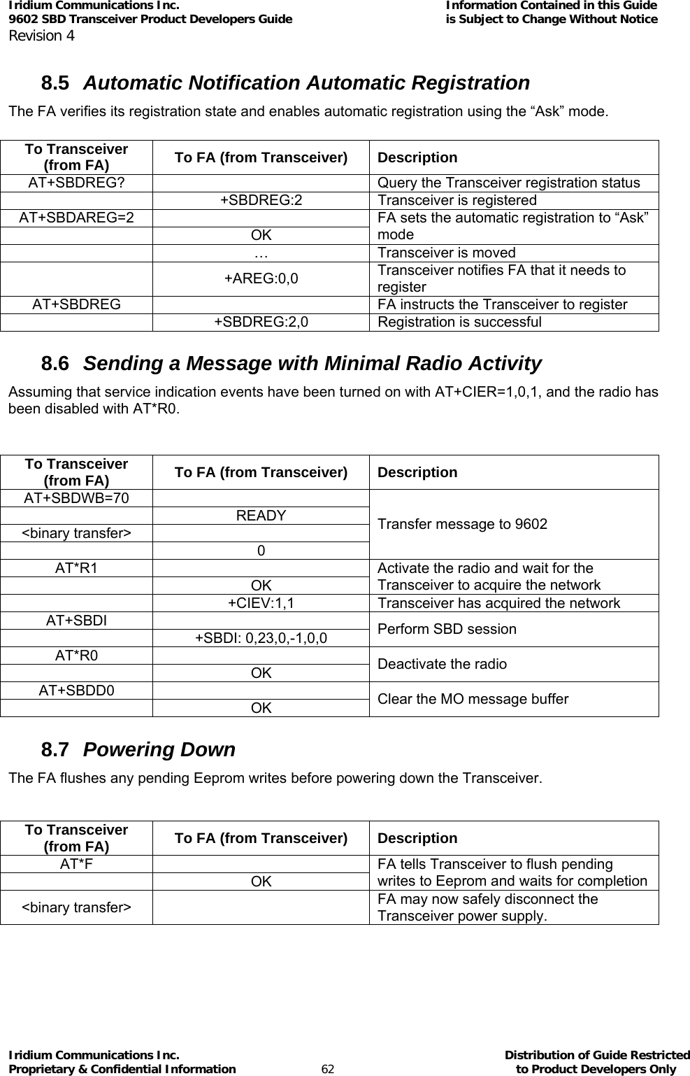
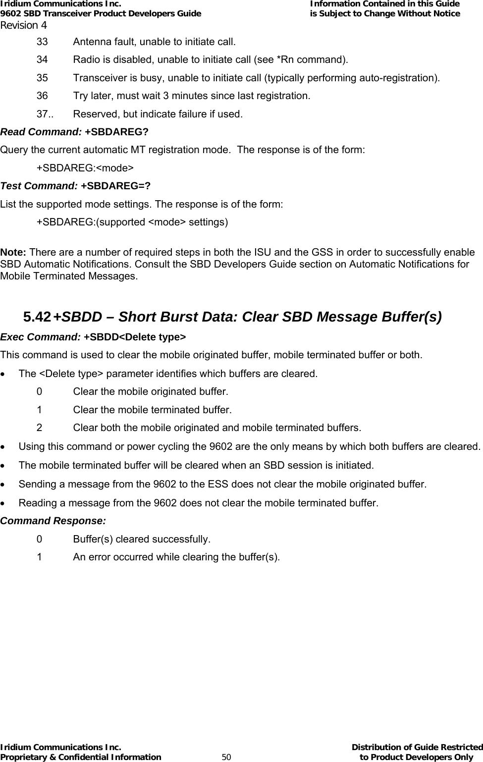
![Iridium Communications Inc. Information Contained in this Guide 9602 SBD Transceiver Product Developers Guide is Subject to Change Without Notice Revision 4 Iridium Communications Inc. Distribution of Guide Restricted Proprietary & Confidential Information 21 to Product Developers Only 3.3 Serial Data Interface The Serial data interface is used to both command the 9602 and transfer user data to and from the Transceiver. The 9602 presents a 9-wire data port to the FA (Field Application), where the interface is at 3.3V digital signal levels. With respect to this interface, the 9602 behaves as a DCE (Data Communication Equipment), and the FA behaves as a DTE (Data Terminal Equipment). The terms “FA” and “DTE” are used interchangeably throughout this document; similarly for the terms “9602” and “DCE”. Autobaud is not supported in 9602 SBD Transceiver. The baud rate can be set via the AT+IPR command. The default rate is 19200 bps. 3.3.4 9-Wire and 3-Wire Operation By default, the serial interface operates as a 9-wire connection. Table 10 describes each of the signals, where “input” means an input to the 9602, and “output” means an output from the 9602 SBD Transceiver. Table 10 – Serial Interface Signals Signal Description RX Active high data output [The DTE receives the data from the 9602] TX Active high data input [Data is transmitted from the DTE to the 9602] GND 0V RTS Active low flow control input CTS Active low flow control output RTS and CTS are used together to implement hardware flow control when enabled with AT&K3 DTR Active low handshaking input AT&Dn controls how the 9602 uses DTR: • If set to AT&D0, DTR is always ignored. • Otherwise DTR set to OFF places the data port into UART test mode after 10 seconds, or immediately on boot-up. A subsequent transition of DTR to ON returns the data port to DCE mode and resets it to its power-on state. • The UART test mode is provided for factory testing of the data port UART. An FA should never activate test mode; if it does, the 9602 will stop responding to AT commands until the data port is returned to DCE mode. DSR Active low handshaking output The 9602 drives DSR ON when the data port is in DCE mode, and OFF when the data port is in test mode. The DTE may use this signal as an indication that the 9602 is powered up and ready to receive AT commands. RI Active low ring indicator output The 9602 drives RI ON when it receives a Automatic Notification from the network that a Mobile Terminated SBD Message is queued at the Gateway, and drives RI OFF after 5 seconds or when the DTE initiates an SBD session, whichever occurs first. DCD Active low handshaking output DCD is driven OFF at all times. Note that the Ring Indicator (RI) pin is used by the 9602 SBD Transceiver to indicate that a Mobile Terminated SBD (MT-SBD) message is queued at the Gateway. The Field Application can monitor this pin and use appropriate AT Commands to command the Transceiver to retrieve the MT-SBD message.](https://usermanual.wiki/Iridium-Satellite/9602.manual/User-Guide-1265166-Page-21.png)
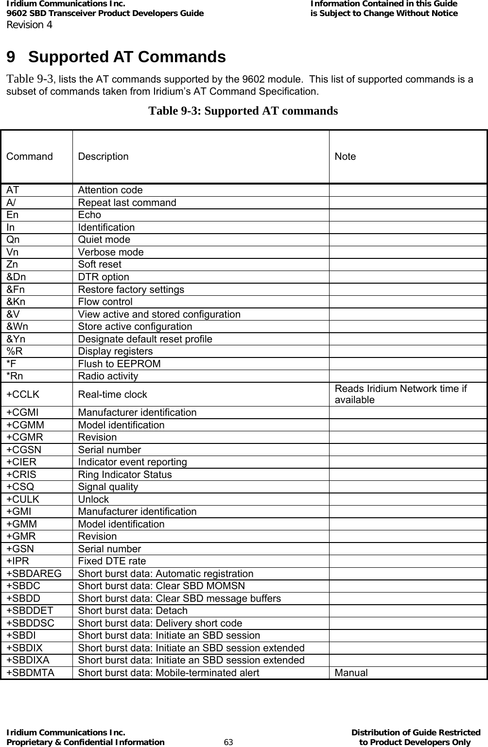
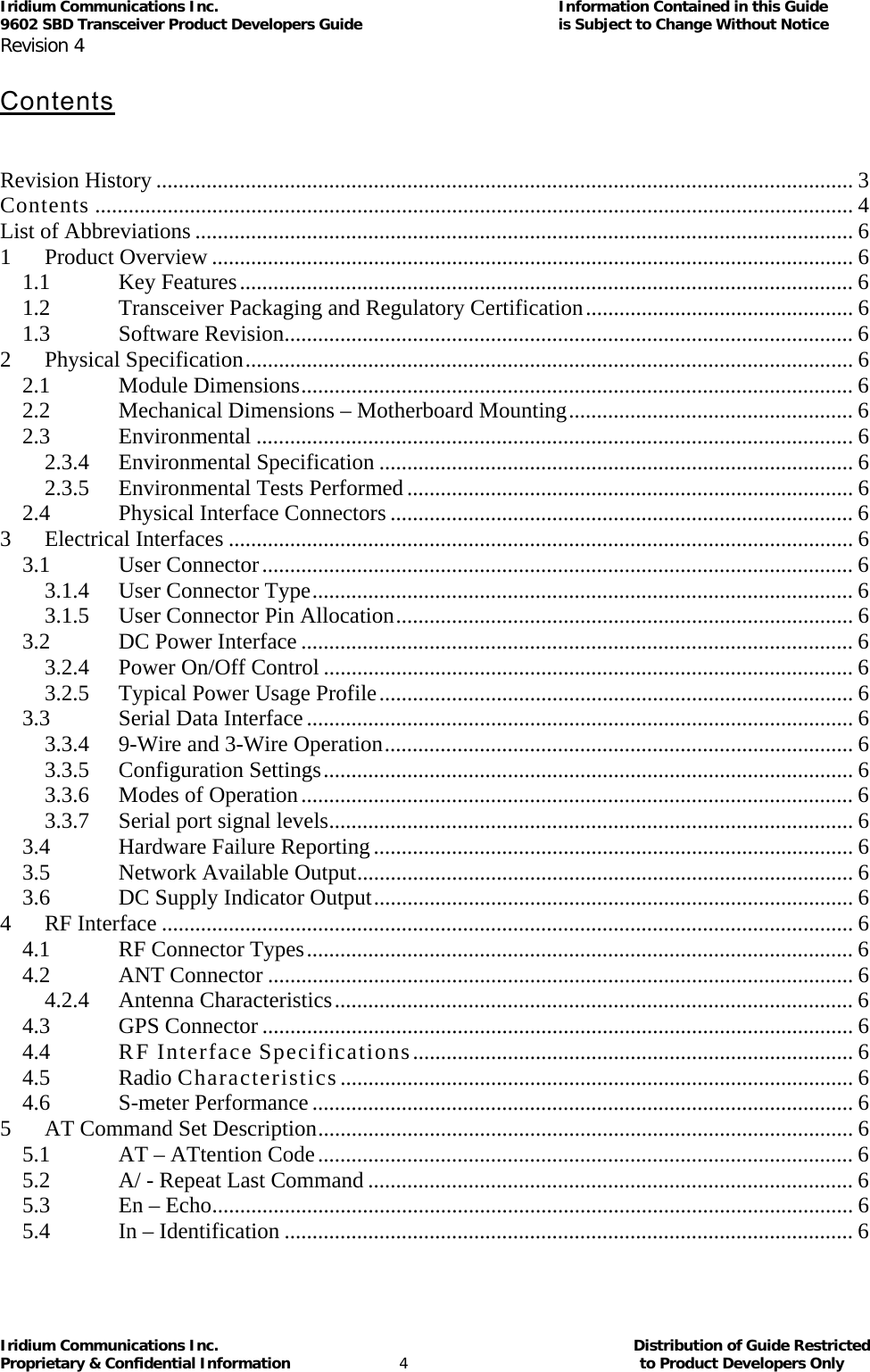
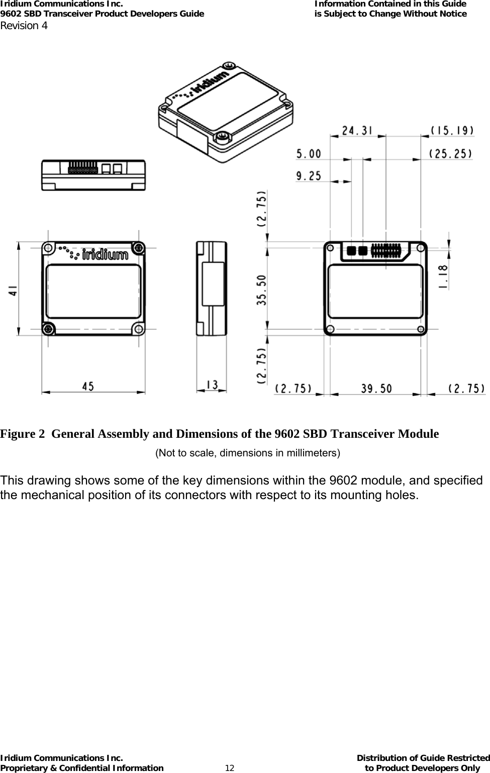
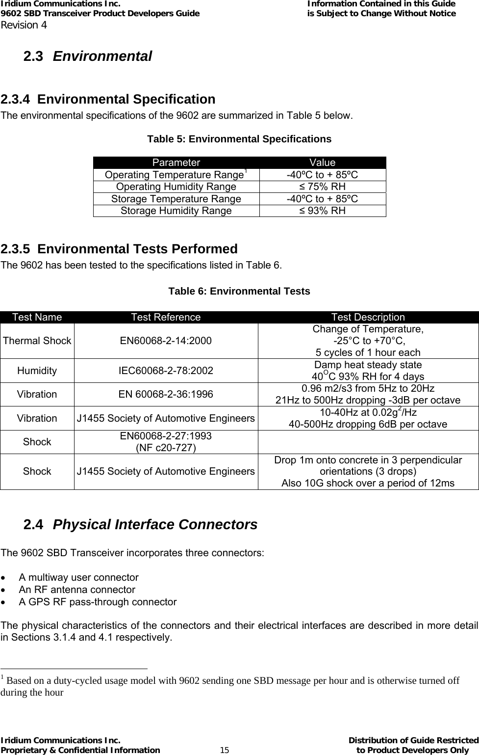
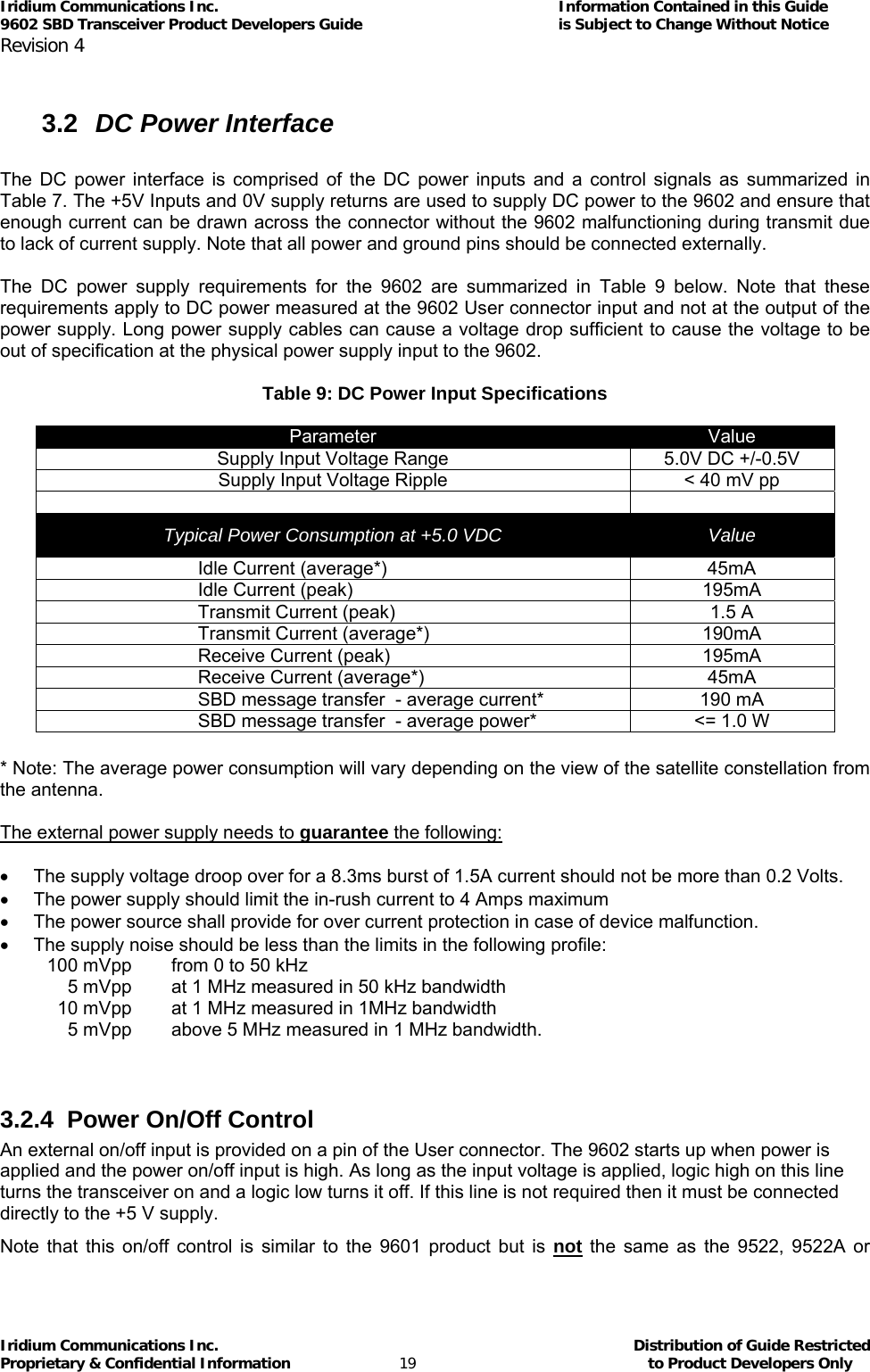
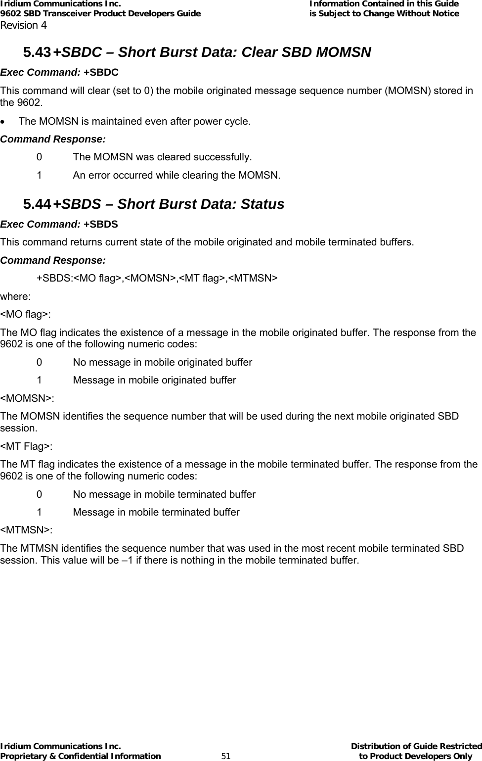
![Iridium Communications Inc. Information Contained in this Guide 9602 SBD Transceiver Product Developers Guide is Subject to Change Without Notice Revision 4 Iridium Communications Inc. Distribution of Guide Restricted Proprietary & Confidential Information 23 to Product Developers Only 3.3.6 Modes of Operation The serial interface is always in one of three modes: command mode, SBD data mode or SBD session mode. When the data port is in command mode, AT commands can be entered to control the 9602. In command mode, flow control has no effect, with the RTS input ignored and the CTS output driven ON (low). When in SBD data mode, the 9602 is transferring binary or text SBD message data to or from the DTE. In SBD data mode: • All characters from the DTE not forming part of the message data are ignored (i.e. no AT commands may be entered) • No unsolicited result codes are issued. • RTS/CTS flow control, if enabled, is active. When RTS is OFF (high), the 9602 suspends transfer of data to the DTE; when CTS is OFF (high), the 9602 expects the DTE to suspend transfer of data to the 9602. When in SBD session mode, the 9602 is attempting to conduct an SBD session with the network. In SBD session mode: • The DTE must wait for the +SBDI [X][A]session result code. • All characters from the DTE are ignored. • Unsolicited result codes are issued where those codes have been enabled. Transitions between the modes of operation are performed automatically by the 9602 in response to the SBD AT Commands; the DTE has no other control over the mode. 3.3.7 Serial port signal levels 3.3.7.1 Data Port Inputs The inputs on the 9602 serial port (RTS, DTR and TXD) will operate correctly at 3.3V digital signal levels. RS-232 interface chips can be fitted to the host system motherboard if connection to an external RS232 link is required. Note that these may invert the digital logic level, so another inversion may be required. 3.3.7.2 Data Port Outputs The five outputs from the 9602 serial port (DCD, DSR, CTS, RI and RXD) are all at 3.3V digital levels. 3.4 Hardware Failure Reporting If the 9602 detects a hardware problem during initialisation, the 9602 may be unable to function correctly. The 9602 notifies the DTE of this situation by issuing an unsolicited result code at the end of initialisation: HARDWARE FAILURE: <subsys>,<error> where <subsys> identifies the software subsystem that detected the error, and <error> is the subsystem-specific error code. Any AT commands that cannot be handled in the failure condition will terminate with result code 4 (“ERROR”).](https://usermanual.wiki/Iridium-Satellite/9602.manual/User-Guide-1265166-Page-23.png)
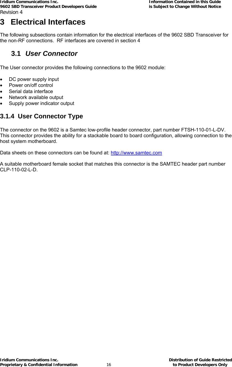
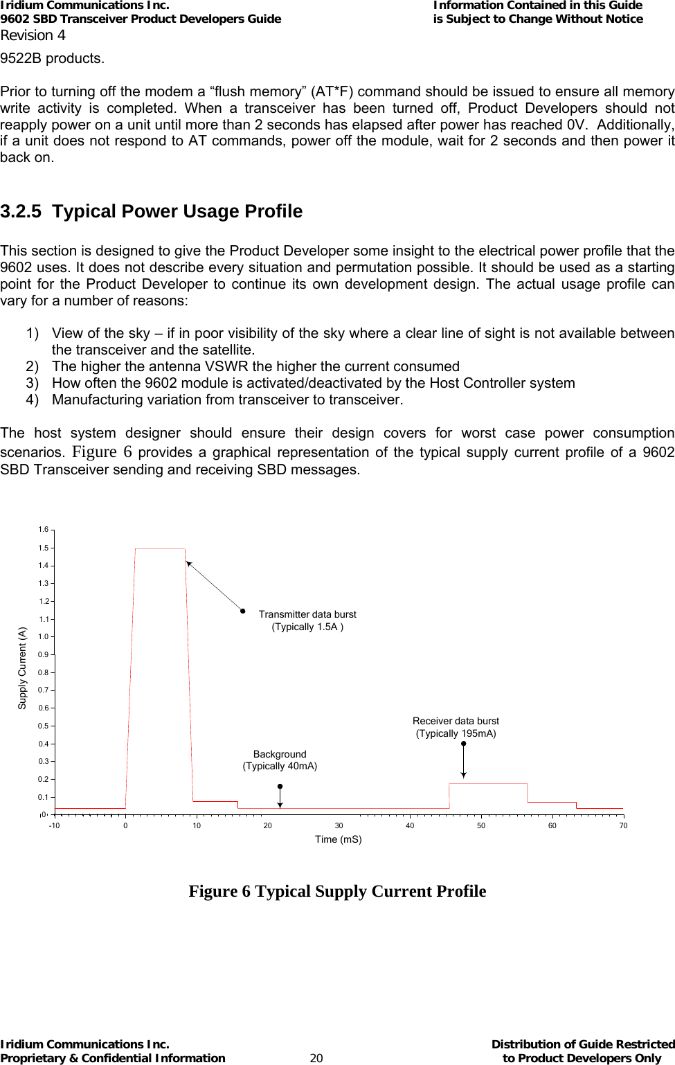
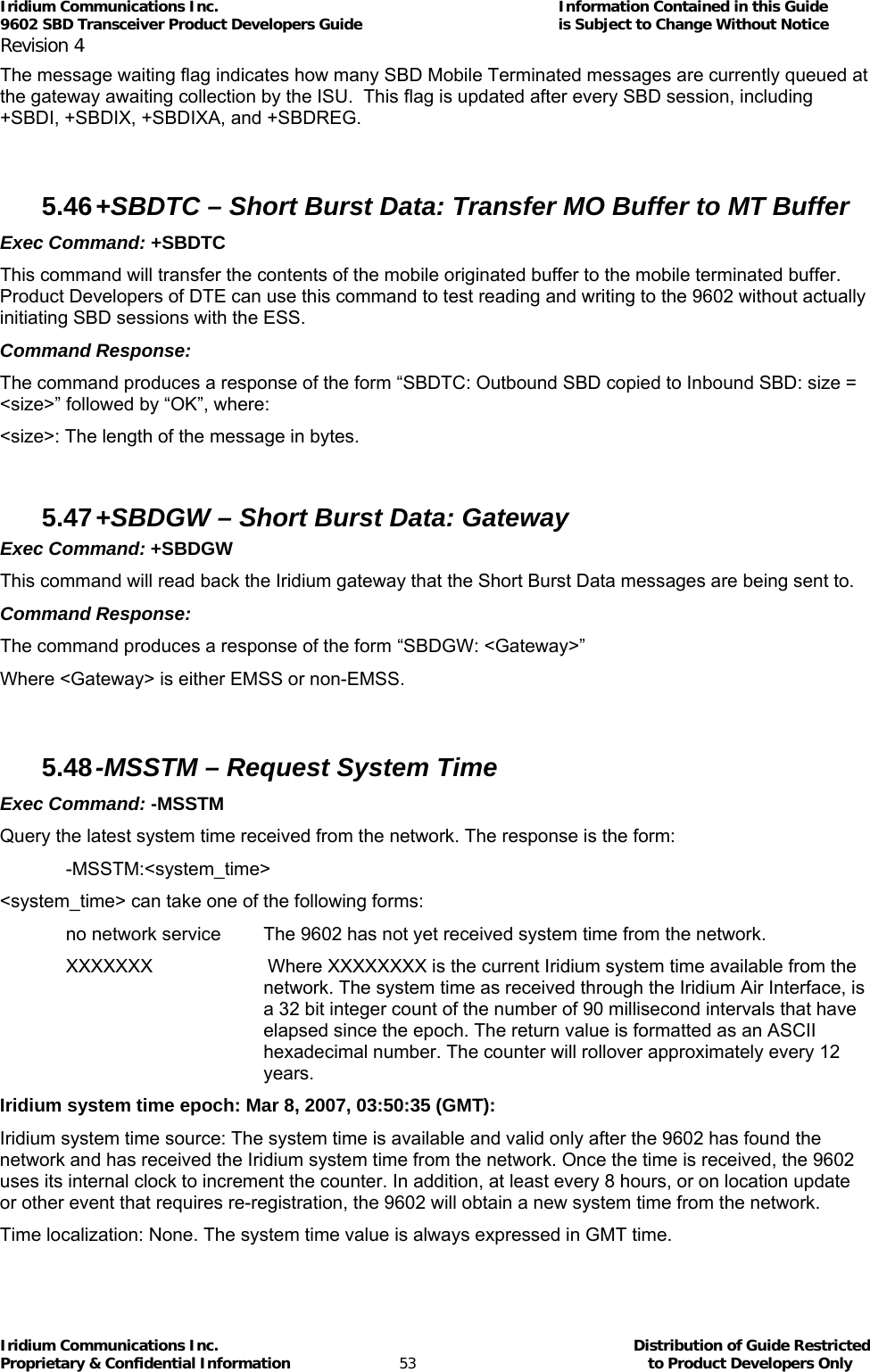
![Iridium Communications Inc. Information Contained in this Guide 9602 SBD Transceiver Product Developers Guide is Subject to Change Without Notice Revision 4 Iridium Communications Inc. Distribution of Guide Restricted Proprietary & Confidential Information 24 to Product Developers Only 3.5 Network Available Output This is a digital output that can be used by an application to know when the Transceiver has visibility to the satellite network. This is useful in applications where the Transceiver may move around terrain that reduces the amount of time that clear line of sight to the satellite constellation is available. The Product Developer can use this output to preserve battery life by reducing the number of attempted transmissions by including this logic output in the application decision logic. Network Available means only that the 9602 can successfully receive the Ring Channel, or, put more simply, it can see an Iridium satellite. Network Available is not a guarantee that a message can be successfully sent. The Network Available state is evaluated every time the Ring Channel is received or missed. If the Ring Channel is visible, then that is typically every 4 seconds. If the Ring Channel is not currently visible, then the update period can be as long as 2 minutes, depending on how long the lack of satellite visibility existed. This is because the 9602 attempts to conserve power by increasing the ring search interval while the satellites are not visible. Every time a ring search fails, the time to wait is increased and eventually limits at 120 seconds. If Network Available is currently off, the Field Application may still attempt an SBDI[X] session. This will force the 9602 Transceiver to look for the Ring Channel immediately, and on finding it, to attempt to send the message. In this case Network Available will not come on immediately. The Network Available does not turn on while in a +SBDI session. It will however turn on 4 seconds later assuming that the Ring Channel is present. After the SBD session completes, the 9602 performs a new Ring Channel search sequence, at the end of which Network Available gets turned on. That can take between 4 and 12 seconds. The wait time between search windows is reset to 4 seconds every time a search succeeds. Otherwise it continues to increase. So if the +SBDI attempt fails to find the ring channel, the search window does not reset to 4 seconds. Note that the behavior of +CIEV:1 is identical in to that of the Network Available output. 3.6 DC Supply Indicator Output A DC supply indicator signal is provided by the 9602 which could be used directly for driving an LED to provide a visible indication that the Transceiver supply is on. Alternatively the output signal could be used in application logic to determine if the internal Transceiver power supply is on.](https://usermanual.wiki/Iridium-Satellite/9602.manual/User-Guide-1265166-Page-24.png)
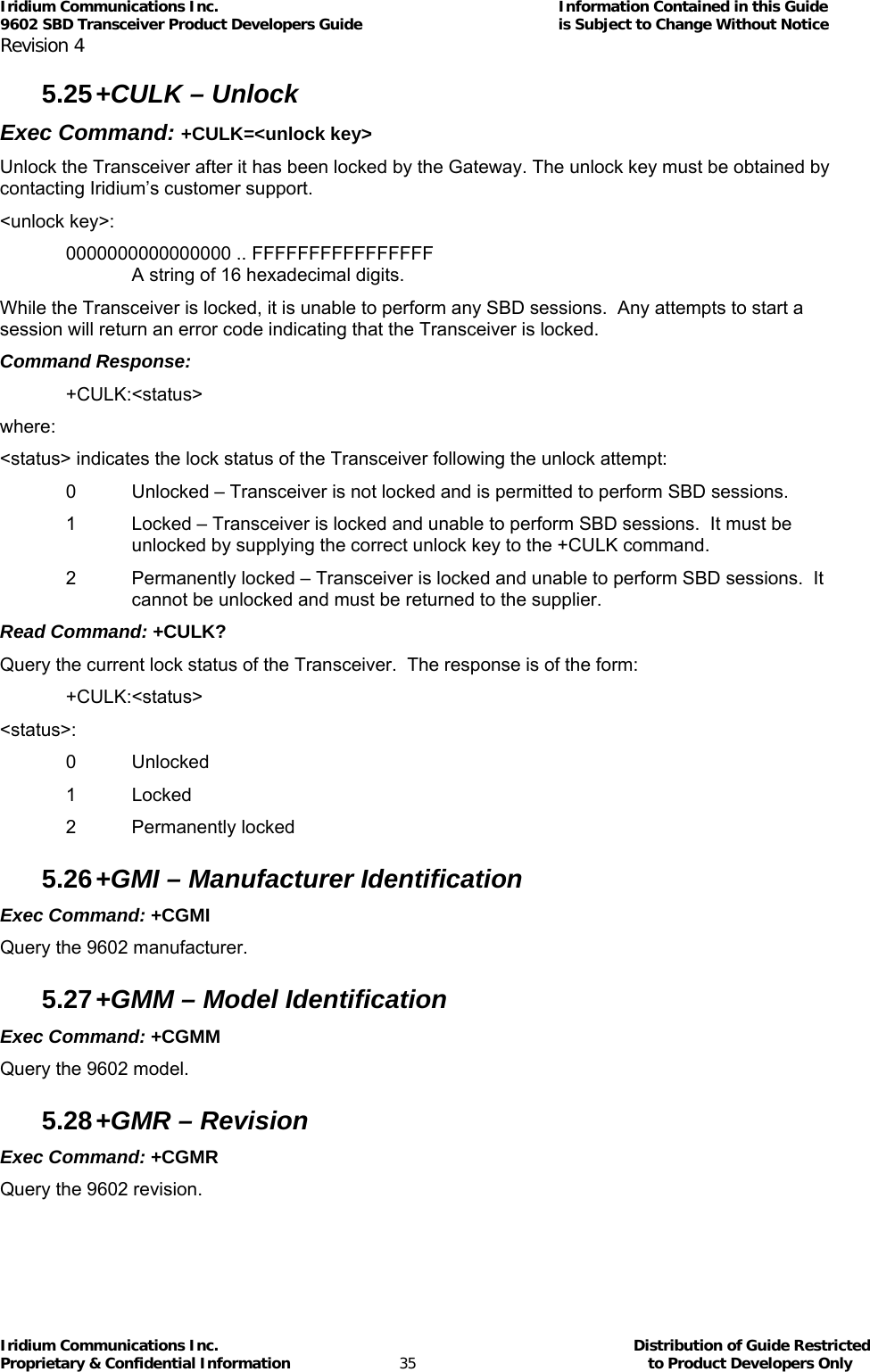
![Iridium Communications Inc. Information Contained in this Guide 9602 SBD Transceiver Product Developers Guide is Subject to Change Without Notice Revision 4 Iridium Communications Inc. Distribution of Guide Restricted Proprietary & Confidential Information 32 to Product Developers Only 5.22 +CIER – Indicator Event Reporting Set Command: +CIER=[<mode>[,<sigind>[,<svcind>]]] The set command enables or disables sending of the +CIEV unsolicited result code from the 9602 to the DTE in case of indicator state changes. <mode> controls the processing of the +CIEV unsolicited result codes. <mode>: 0 Disable indicator event reporting; do not send +CIEV unsolicited result codes to the DTE; buffer the most recent indicator event for each indicator in the 9602 (default). 1 Enable indicator event reporting; buffer the most recent +CIEV unsolicited result code for each indicator when the data port is reserved (e.g. in SBD data mode) and flush them to the DTE after reservation; otherwise forward them directly to the DTE. <sigind>: Control reporting of "signal quality" indicator changes: 0 No "signal quality" indicator reporting. 1 Enable "signal quality" indicator reporting using result code +CIEV:0,<rssi> where <rssi> is: 0 Equivalent to 0 bars on the signal strength indicator 1 Equivalent to 1 bars on the signal strength indicator 2 Equivalent to 2 bars on the signal strength indicator 3 Equivalent to 3 bars on the signal strength indicator 4 Equivalent to 4 bars on the signal strength indicator 5 Equivalent to 5 bars on the signal strength indicator The reported signal strength is the same value that would be returned by the +CSQ command. When enabled, the signal quality indicator is reported only when the signal strength changes. <svcind>: Control reporting of "service availability" indicator changes: 0 No "service availability" indicator reporting. 1 Enable "service availability" indicator reporting using result code +CIEV:1,<value> where <value> is: 0 Network service is currently unavailable. 1 Network service is available.](https://usermanual.wiki/Iridium-Satellite/9602.manual/User-Guide-1265166-Page-32.png)
![Iridium Communications Inc. Information Contained in this Guide 9602 SBD Transceiver Product Developers Guide is Subject to Change Without Notice Revision 4 Iridium Communications Inc. Distribution of Guide Restricted Proprietary & Confidential Information 34 to Product Developers Only 5.24 +CSQ – Signal Quality Exec Command: +CSQ[F] Execution command returns the received signal strength indication <rssi> from the 9602. Response is in the form: +CSQ:<rssi> where: <rssi>: 0 Equivalent to 0 bars displayed on the signal strength indicator. 1 Equivalent to 1 bar displayed on the signal strength indicator. 2 Equivalent to 2 bars displayed on the signal strength indicator. 3 Equivalent to 3 bars displayed on the signal strength indicator. 4 Equivalent to 4 bars displayed on the signal strength indicator. 5 Equivalent to 5 bars displayed on the signal strength indicator. Test Command: +CSQ=? List the supported signal strength indications. The response is in the form: +CSQ:(supported <rssi>s) Note: A signal strength response may not be immediately available, but will usually be received within two seconds of issuing the command. If the 9602 is in the process of acquiring the system, a delay in response of up to 50 seconds may be experienced. Note: The +CSQF form of the command returns immediately, reporting the last known calculated signal strength. Note that the signal strength returned by this command could be different from the current actual signal strength if the +CSQ form is used. This form is included for Product Developer application compatibility as it provides a Fast response.](https://usermanual.wiki/Iridium-Satellite/9602.manual/User-Guide-1265166-Page-34.png)
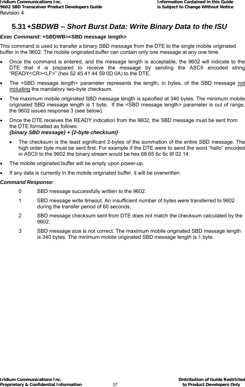
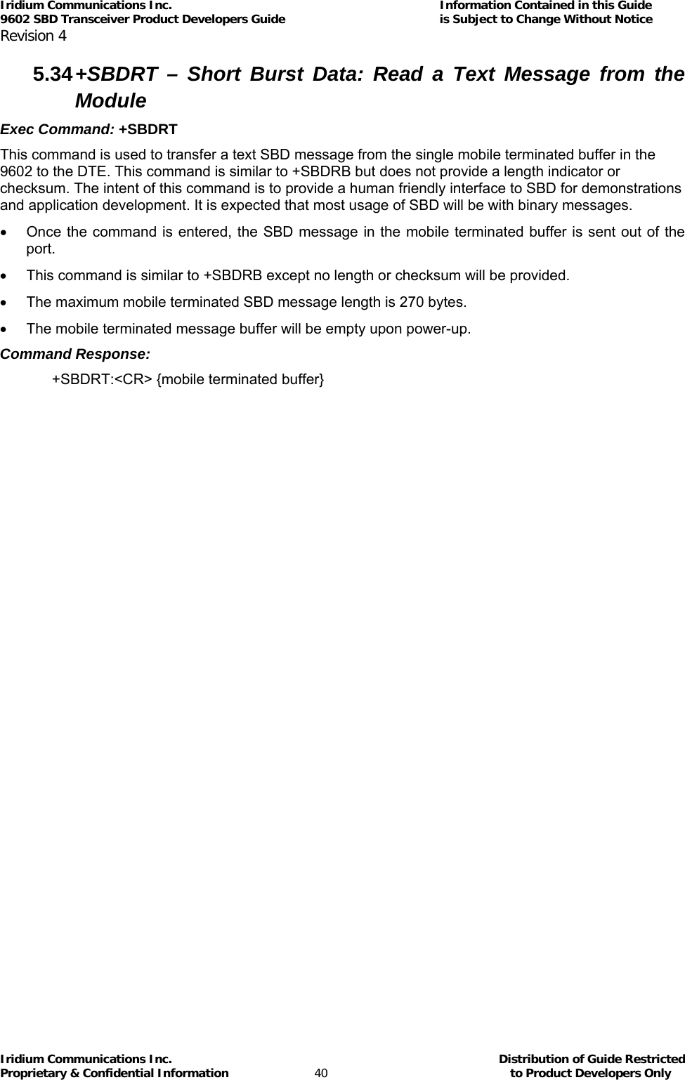
![Iridium Communications Inc. Information Contained in this Guide 9602 SBD Transceiver Product Developers Guide is Subject to Change Without Notice Revision 4 Iridium Communications Inc. Distribution of Guide Restricted Proprietary & Confidential Information 39 to Product Developers Only 5.33 +SBDWT – Short Burst Data: Write a Text Message to the Module Exec Command: +SBDWT[=<text message>] This command is used to transfer a text SBD message from the DTE to the single mobile originated buffer in the 9602. The text message may be entered on the command line: • For example, “AT+SBDWT=hello”. • The length of <text message> is limited to 120 characters. This is due to the length limit on the AT command line interface. • The message is terminated when a carriage return is entered. Alternatively, the text message may be entered separately: • Upon entering the command “AT+SBDWT”, the 9602 will indicate to the DTE that it is prepared to receive the message by sending the string “READY<CR><LF>” (hex 52 45 41 44 59 0D 0A) to the DTE. • Once the DTE receives the READY indication, the text message must be sent, terminated by a carriage return. • The length of the text message entered in this way is limited only by maximum mobile-originated SBD message length of 340 bytes. • The mobile originated buffer will be empty upon power-up. • If any data is currently in the mobile originated buffer, it will be overwritten. Command Response: For the “AT+SBDWT” form: 0 SBD message successfully written to the 9602. 1 SBD message write timeout. An insufficient number of bytes were transferred to 9602 during the transfer period of 60 seconds. For the “AT+SBDWT=<text message>” form: OK: SBD message successfully stored in mobile originated buffer. ERROR: An error occurred storing SBD message in mobile originated buffer.](https://usermanual.wiki/Iridium-Satellite/9602.manual/User-Guide-1265166-Page-39.png)
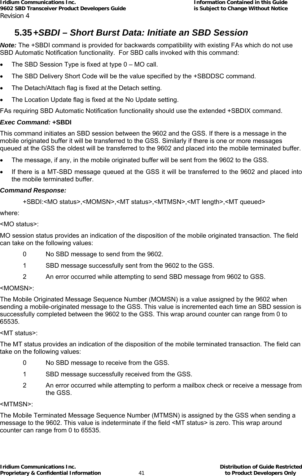
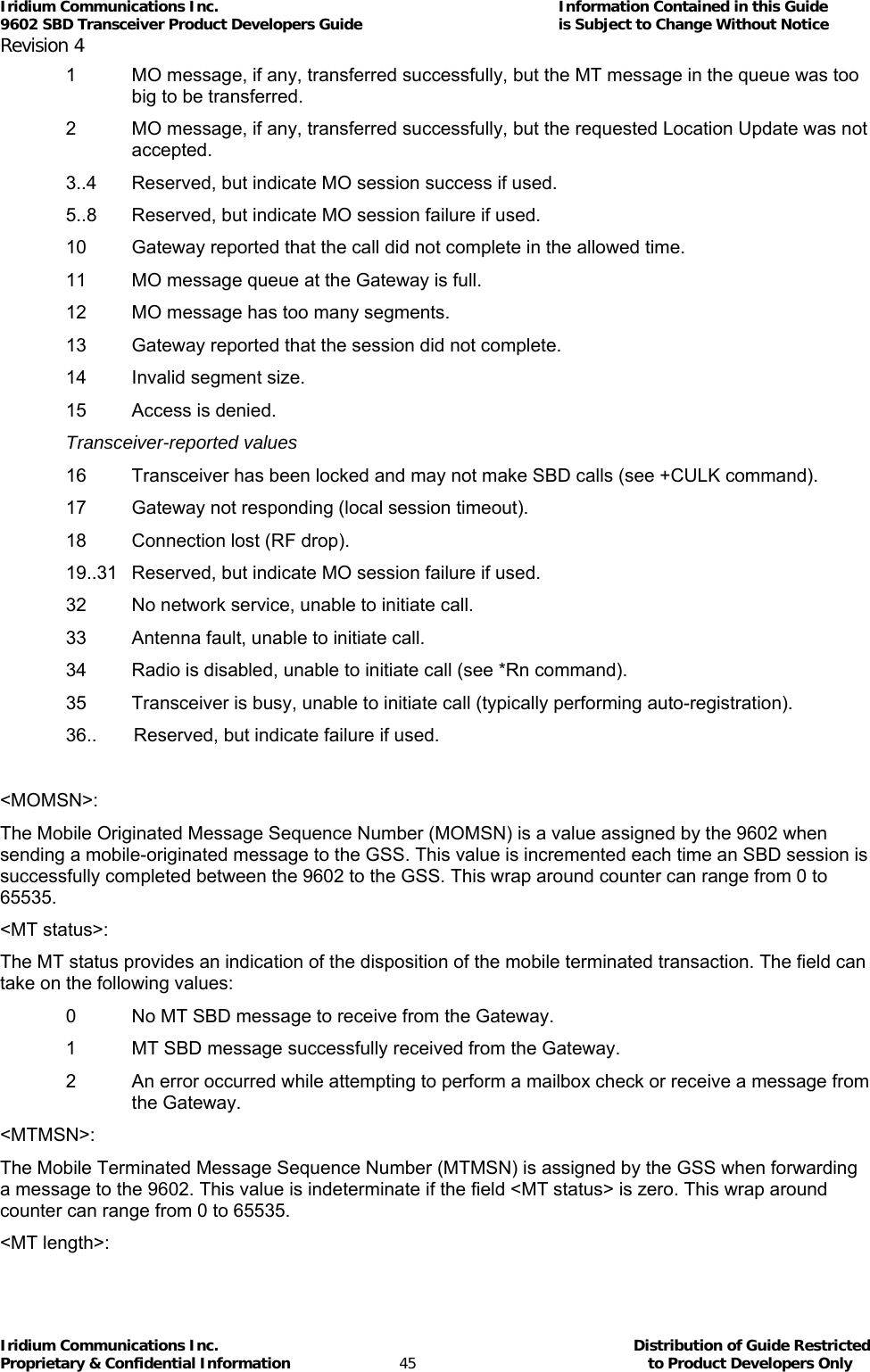
![Iridium Communications Inc. Information Contained in this Guide 9602 SBD Transceiver Product Developers Guide is Subject to Change Without Notice Revision 4 Iridium Communications Inc. Distribution of Guide Restricted Proprietary & Confidential Information 44 to Product Developers Only 5.38 +SBDIX – Short Burst Data: Initiate an SBD Session Extended Note: The +SBDIX command must be used in place of the +SBDI command for FAs wishing to make use of SBD Automatic Notification functionality. Exec Command: +SBDIX[A][=<location>] This command initiates an SBD session between the 9602 and the GSS, setting the SBD Session Type according to the type of command +SBDIX or +SBDIXA, Delivery Short Code according to the value specified by the +SBDDSC command, and the type of location according to whether the optional location value is provided. If there is a message in the mobile originated buffer it will be transferred to the GSS. Similarly if there is one or more MT messages queued at the GSS the oldest will be transferred to the 9602 and placed into the mobile terminated buffer. • The message, if any, in the mobile originated buffer will be sent from the 9602 to the GSS. • If there is a MT message queued at the GSS it will be transferred to the 9602 and placed into the mobile terminated buffer. • This command will always attempt an SBD Network Registration, consisting of attach and location update, during the SBD session in order to support SBD Automatic Notification. If this is not desired, the +SBDI command should be used. • The FA should append an ‘A’ to the command, i.e. +SBDIXA, when the SBD session is in response to SBD Ring Alert. If this option is not used, more than one SBD Ring Alert may be received. <location> has format: [+|-]DDMM.MMM,[+|-]dddmm.mmm where: DD Degrees latitude (00-89) MM Minutes latitude (00-59) MMM Thousandths of minutes latitude (000-999) ddd Degrees longitude (000-179) mm Minutes longitude (00-59) mmm Thousandths of minutes longitude (000-999) The optional sign indicators specify latitude North (+) or South (-), and longitude East (+) or West (-). If omitted, the default is +. For example, AT+SBDIX=5212.483,-00007.350 corresponds to 52 degrees 12.483 minutes North, 0 degrees 7.35 minutes West. Command Response: +SBDIX:<MO status>,<MOMSN>,<MT status>,<MTMSN>,<MT length>,<MT queued> where: <MO status>: MO session status provides an indication of the disposition of the mobile originated transaction. The field can take on the following values: Gateway-reported values 0 MO message, if any, transferred successfully.](https://usermanual.wiki/Iridium-Satellite/9602.manual/User-Guide-1265166-Page-44.png)
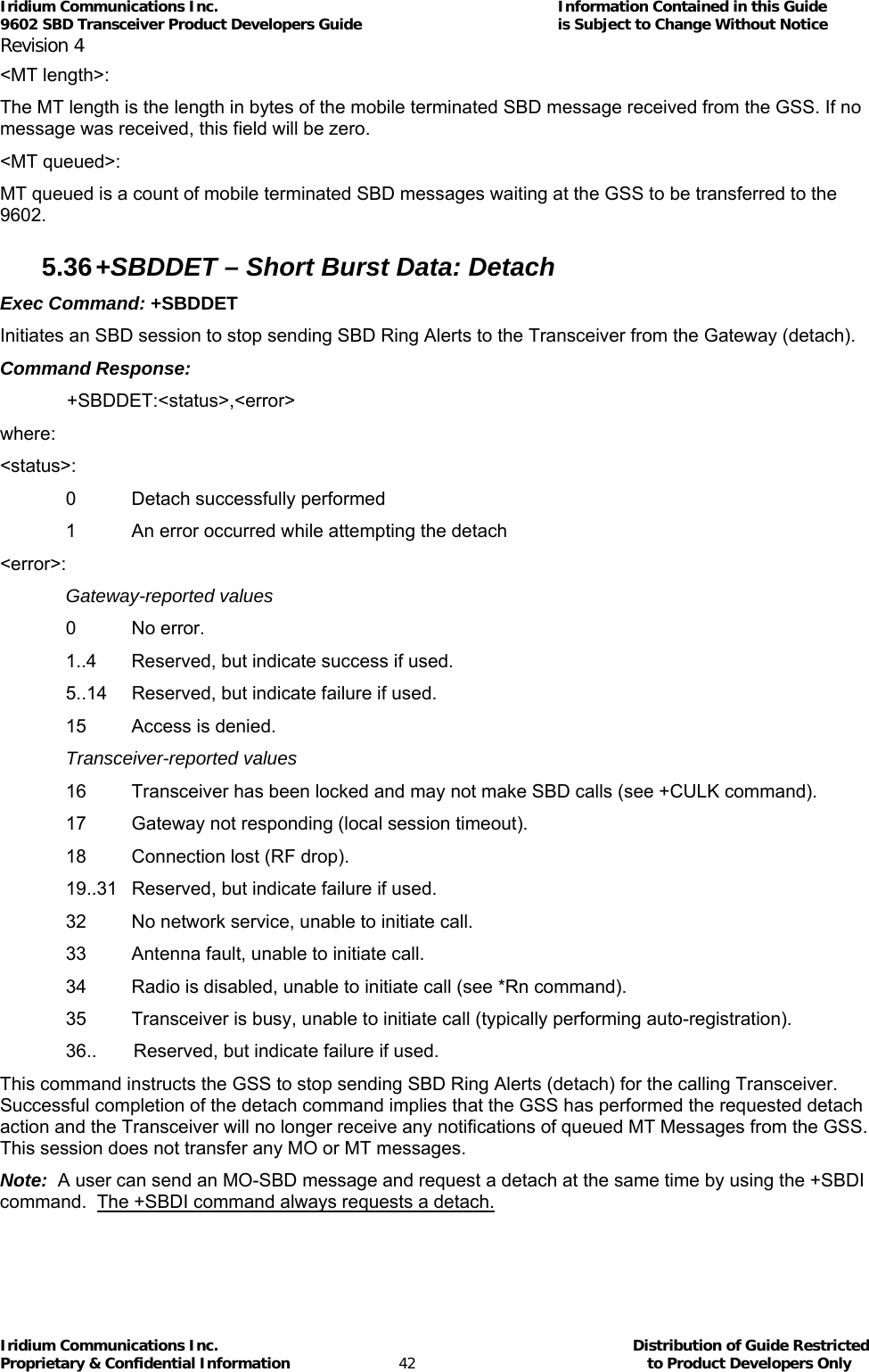
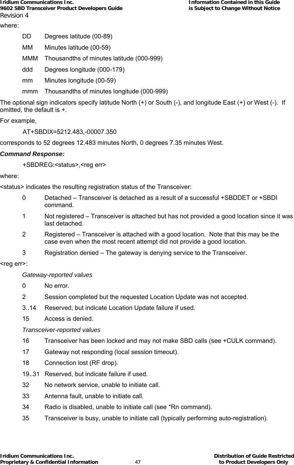
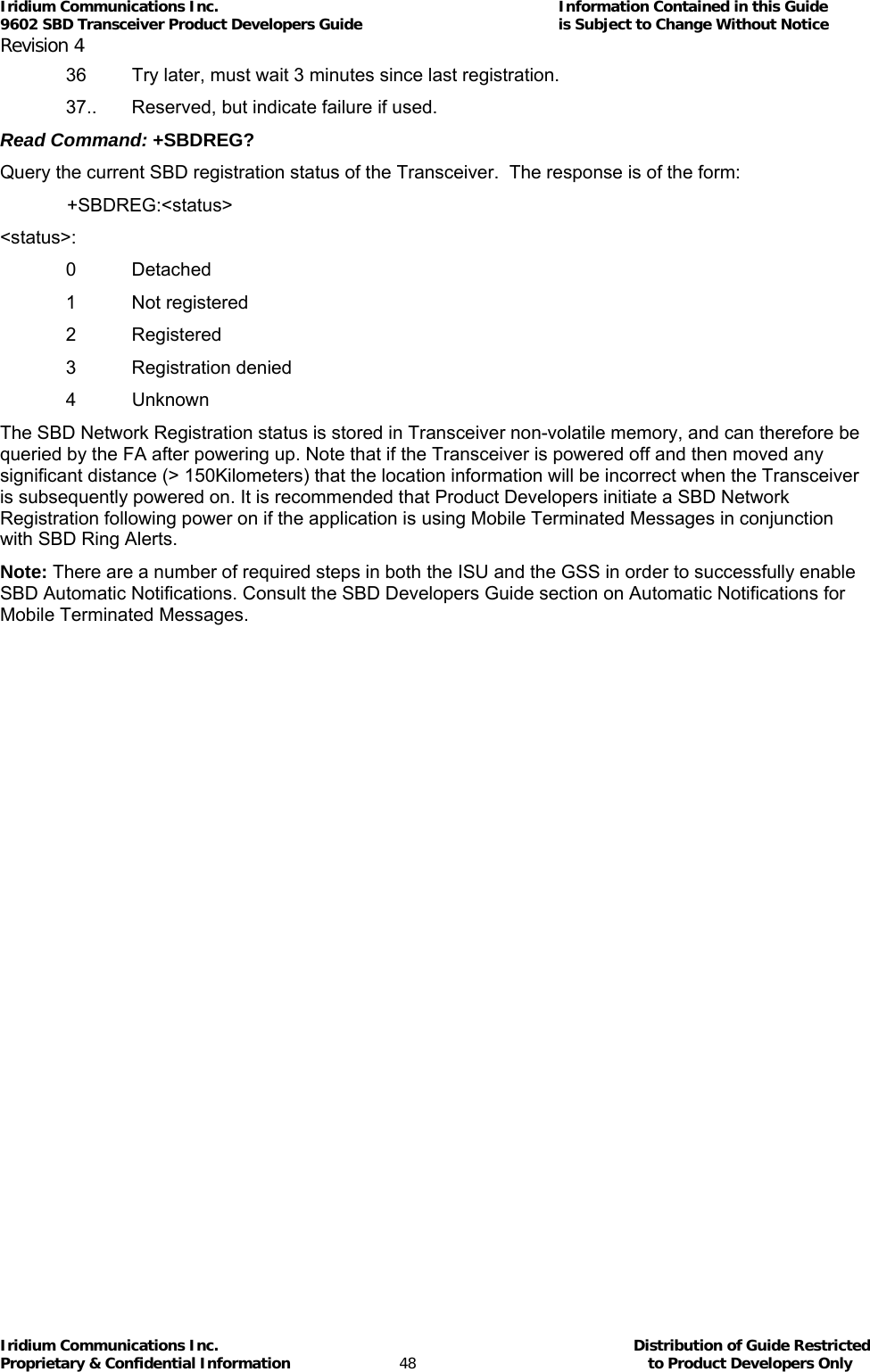
![Iridium Communications Inc. Information Contained in this Guide 9602 SBD Transceiver Product Developers Guide is Subject to Change Without Notice Revision 4 Iridium Communications Inc. Distribution of Guide Restricted Proprietary & Confidential Information 46 to Product Developers Only The MT length is the length in bytes of the mobile terminated SBD message received from the GSS. If no message was received, this field will be zero. <MT queued>: MT queued is a count of mobile terminated SBD messages waiting at the GSS to be transferred to the 9602. 5.39 +SBDMTA – Short Burst Data: Mobile-Terminated Alert Set Command: +SBDMTA=<mode> Enable or disable the ISU to listen for SBD Ring Alerts. <mode>: 0 Disable SBD Ring Alert indication 1 Enable SBD Ring Alert ring indication (default) When SBD Ring Alert indication is enabled, the 9602 asserts the RI line and issues the unsolicited result code SBDRING when an SBD Ring Alert is received. Read Command: +SBDMTA? Query the current ring indication mode. The response is of the form: +SBDMTA:<mode> Test Command: +SBDMTA=? List the supported mode settings. The response is of the form: +SBDMTA:(supported <mode> settings) Note: There are a number of required steps in both the ISU and the GSS in order to successfully enable SBD Automatic Notifications. Consult the SBD Developers Guide section on Automatic Notifications for Mobile Terminated Messages. 5.40 +SBDREG – Short Burst Data: Network Registration Exec Command: +SBDREG[=<location>] Triggers an SBD session to perform a manual SBD Network Registration. This command initiates an SBD session to perform a manual SBD Network Registration, consisting of an attach and location update. The session type will be set to 2 – registration. This session does not transfer any MO or MT message(s). Note: The Transceiver restricts the number of manual and automatic registrations to one every 3 minutes. Successive attempts within 3 minutes will return an error code indicating that the FA should try later (see error 36 below). Note: A user can send an MO SBD message and perform a SBD Network Registration at the same time by using the +SBDIX command. The +SBDIX command always performs a SBD Network Registration attempt and should be used for an application requiring SBD Automatic Notification. The +SBDI command never includes an SBD Network registration and should be used for an application that does not require SBD Automatic Notification. Note: If you are not using MT-SBD messages there is no requirement or benefit to using this command. <location> has format: [+|-]DDMM.MMM,[+|-]dddmm.mmm](https://usermanual.wiki/Iridium-Satellite/9602.manual/User-Guide-1265166-Page-46.png)
![Iridium Communications Inc. Information Contained in this Guide 9602 SBD Transceiver Product Developers Guide is Subject to Change Without Notice Revision 4 Iridium Communications Inc. Distribution of Guide Restricted Proprietary & Confidential Information 52 to Product Developers Only 5.45 +SBDSX - Short Burst Data: Status Extended Exec Command: +SBDSX This command returns current state of the mobile originated and mobile terminated buffers, and the SBD ring alert status. Command Response: +SBDSX: <MO flag>, <MOMSN>, <MT flag>, <MTMSN>, <RA flag>, <msg waiting> where: <MO flag>: The MO flag indicates the existence of a message in the mobile originated buffer. The response from the ISU is one of the following numeric codes: 0 No message in mobile originated buffer. 1 Message in mobile originated buffer. <MOMSN>: The MOMSN identifies the sequence number that will be used during the next mobile originated SBD session. <MT Flag>: The MT flag indicates the existence of a message in the mobile terminated buffer. The response from the ISU is one of the following numeric codes: 0 No message in mobile terminated buffer. 1 Message in mobile terminated buffer. <MTMSN>: The MTMSN identifies the sequence number that was used in the most recent mobile terminated SBD session. This value will be –1 if there is nothing in the mobile terminated buffer. <RA flag>: The RA flag indicates whether an SBD Ring Alert has been received and still needs to be answered. 0 No SBD ring alert. 1 SBD ring alert has been received and needs to be answered. Note: The RA flag is set whenever the ISU receives an SBD Ring Alert; this happens even if the +SBDMTA setting specifies that SBD ring indications are disabled. The RA flag is cleared only on successful completion of an SBD mailbox check, i.e. an SBD session invoked with +SBDI[X[A]] in which the returned MT status indicates that no error occurred. The value of the RA flag is stored in non-volatile memory so it is preserved across power cycling of the ISU. <msg waiting>:](https://usermanual.wiki/Iridium-Satellite/9602.manual/User-Guide-1265166-Page-52.png)
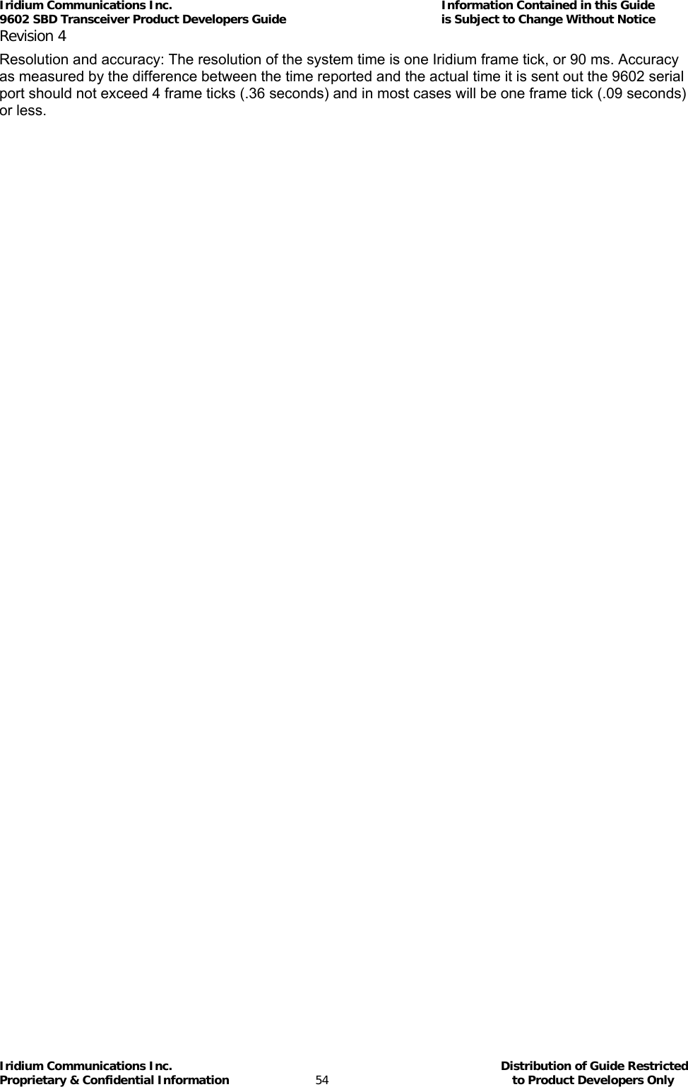
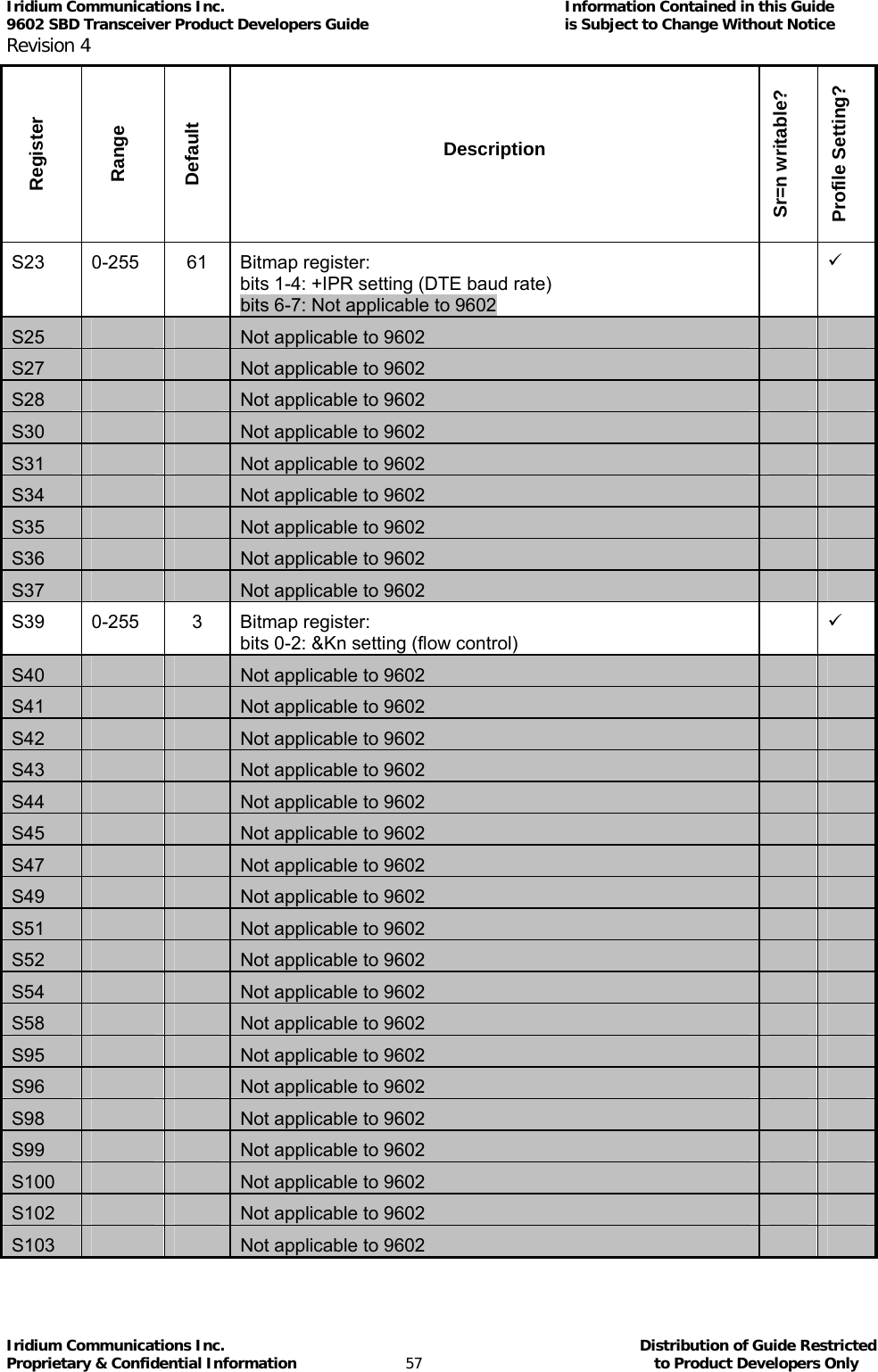
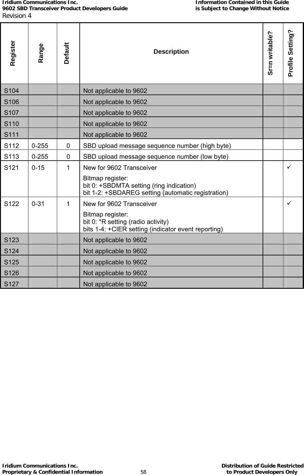
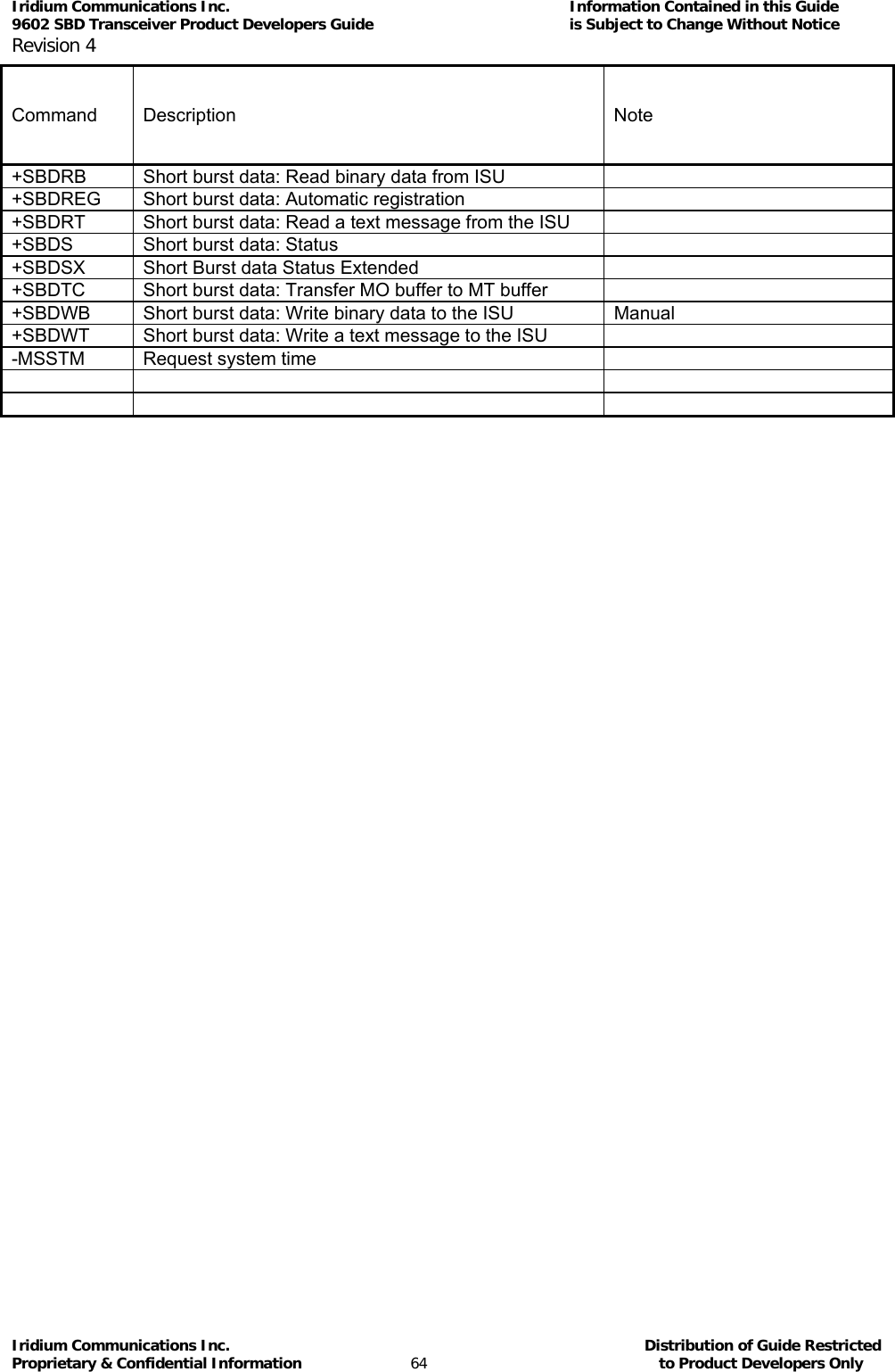
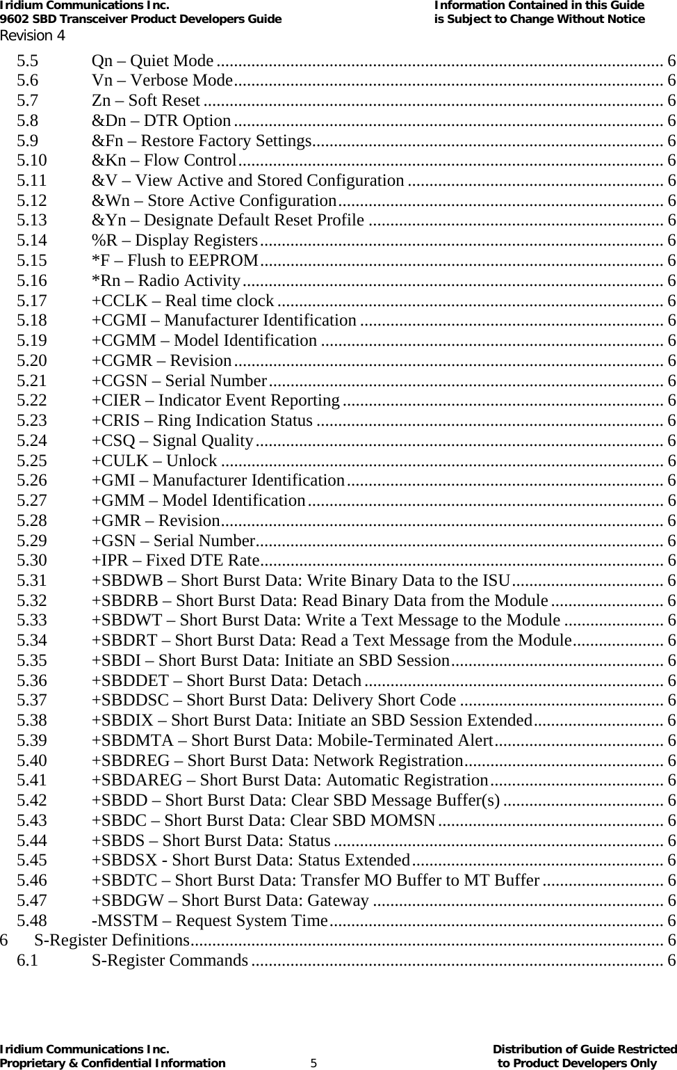
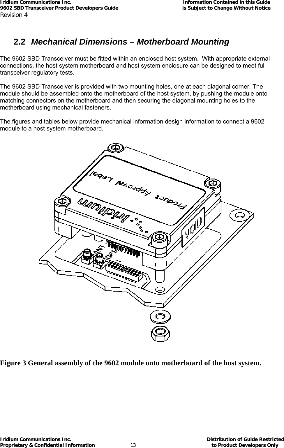
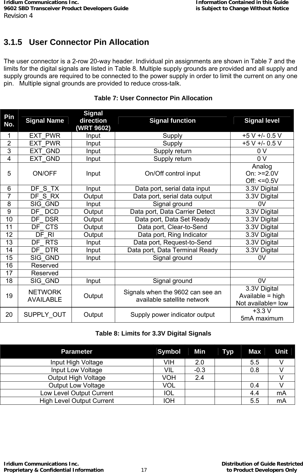
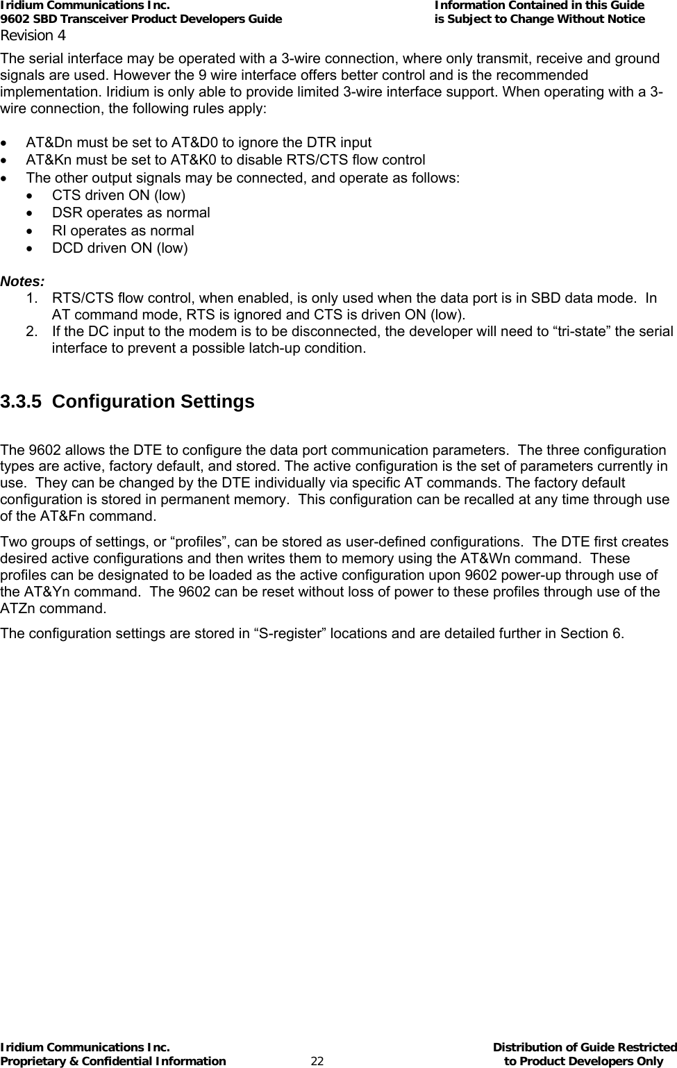
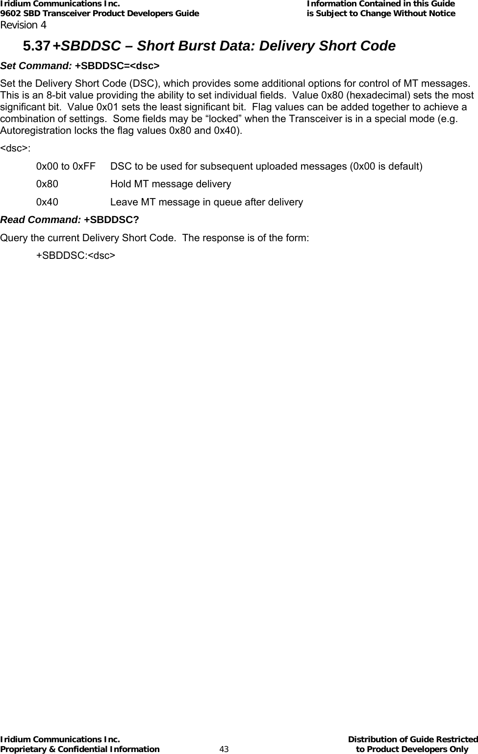
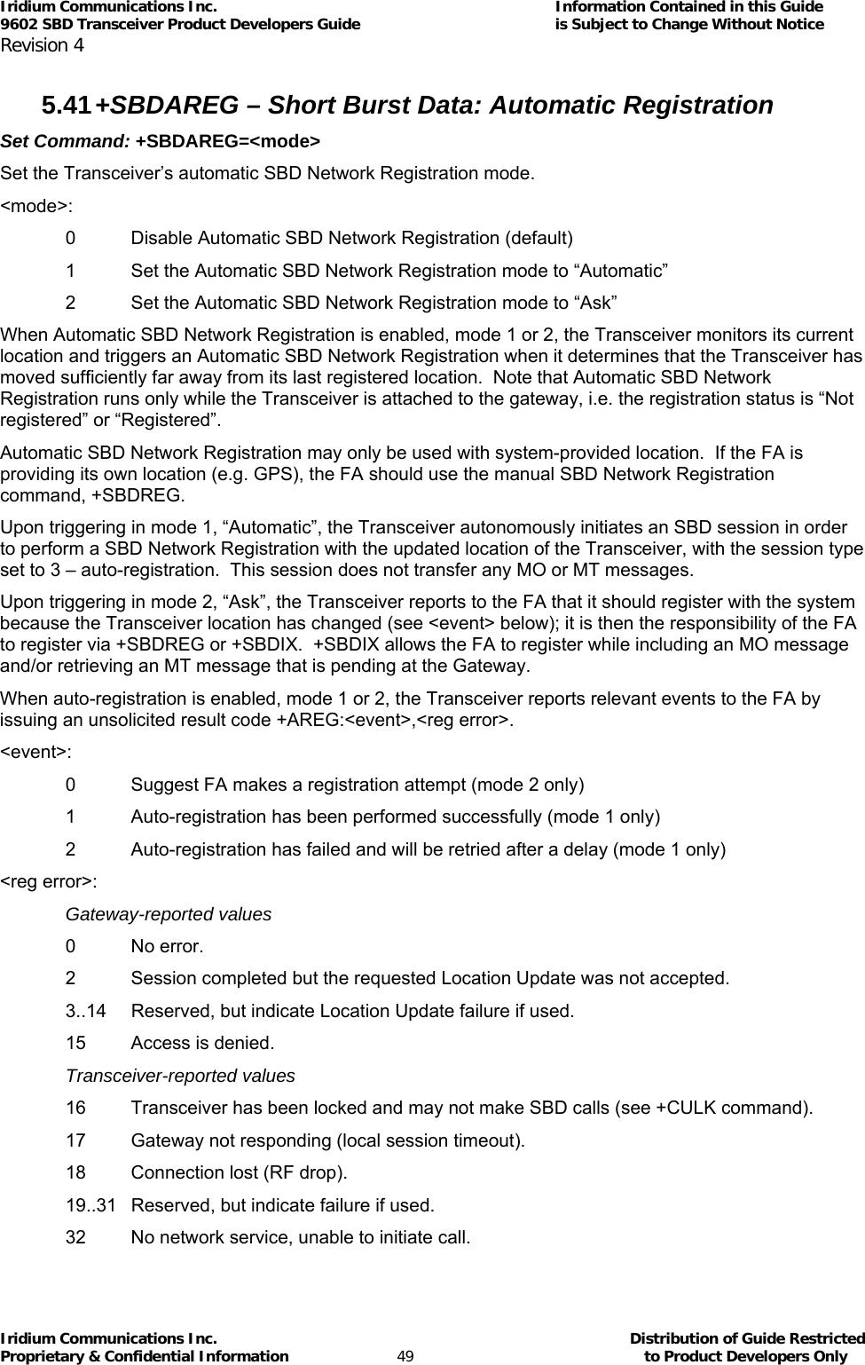
![Iridium Communications Inc. Information Contained in this Guide 9602 SBD Transceiver Product Developers Guide is Subject to Change Without Notice Revision 4 Iridium Communications Inc. Distribution of Guide Restricted Proprietary & Confidential Information 56 to Product Developers Only 6.2 S-Registers Table 6-1: 9602 Transceiver S-Registers [Note: To prevent reallocation of obsolete S-registers, they are reserved and shaded out in the table, and the new S-registers are registers that are unused in 9522A Transceiver and are marked as “new for 9602 Transceiver.”] Register Range Default Description Sr=n writable? Profile Setting? S0 Not applicable to 9602 S1 Not applicable to 9602 S2 0-255 43 Not applicable to 9602Escape code character 9 9 S3 0-127 13 Carriage return character 9 S4 0-127 10 Line feed character 9 S5 0-32 8 Backspace character 9 S6 Not applicable to 9602 S7 Not applicable to 9602 S8 Not applicable to 9602 S9 Not applicable to 9602 S10 Not applicable to 9602 S11 Not applicable to 9602 S12 Not applicable to 9602 S13 0-255 49 Bitmap register: bits 0-1: DCE data bits bits 2-3: DCE stop bits bits 4-6: DCE parity setting 9 S14 0-255 170 Bitmap register: bit 1: En setting (echo) bit 2: Qn setting (quiet) bit 3: Vn setting (verbose) bit 5: Not applicable to 9602 9 9 S21 0-255 48 Bitmap register: bit 0: Not applicable to 9602 bit 2: Not applicable to 9602 bits 3-4: &Dn setting (DTR operation) bit 5: Not applicable to 9602 bit 6: Not applicable to 9602 9 S22 Not applicable to 9602](https://usermanual.wiki/Iridium-Satellite/9602.manual/User-Guide-1265166-Page-56.png)