IsoLynx IL0201 Wireless Tracking Reference Node User Manual 2AHCQ IL0201 Manual
IsoLynx, LLC Wireless Tracking Reference Node 2AHCQ IL0201 Manual
IsoLynx >
User Manual
IsoLynx Reference Node - 2AHCQ-IL0201 1
IsoLynx II Reference Node
IL0201 - User Manual
March 2016

IsoLynx Reference Node - 2AHCQ-IL0201 2
Table of Contents
Introduction ...........................................................................................................................3
Regulatory Information for the United States.........................................................................3
FCC Notice (For US Customers): FCC ID: 2AHCQ-IL0201 Model: IL0201...................3
Hardware & Specifications ....................................................................................................4
IsoLynx Reference Node................................................................................................4
Sample American Football Venue Setup...............................................................................5
Mounting And Placement of Portable Reference Nodes ................................................5
Attaching a USB Power Source .....................................................................................5
Mounting the Reference Nodes to Portable Tripods.......................................................6
Placement and Aim of the Reference Nodes .................................................................6
Dismantling The Reference Nodes After Use.................................................................7
IsoLynx Reference Node Hardware Specifications................................................................7
Main System Components .............................................................................................7
Mechanical.....................................................................................................................7
RF Characteristics..........................................................................................................7

IsoLynx Reference Node - 2AHCQ-IL0201 3
Introduction
The IsoLynx II Reference Node (IL0201) is a USB device that relies on ultra-wideband (UWB) pulses
and time-stamp information to capture real-time location and movement data. The reference node
contains separate receive and transmit antennas so it can receive ultra-wideband pulses from objects
of interest and transmit time-sync data in real time. The reference nodes are attached to tripods and
placed around the perimeter of a playing surface. The system requires a minimum of 4 reference
nodes to produce accurate location data. The nodes are small, wireless, and easily moveable, which
allows for quick setup and tear-down before and after use. This makes the IsoLynx reference nodes
an ideal solution for fast, accurate, and temporary real-time sports tracking.
Regulatory Information for the United States
FCC Notice (For US Customers):
FCC ID: 2AHCQ-IL0201
Model: IL0201
This device complies with Part 15 of the FCC Rules. Operation is subject to the following two
conditions:
1. This device may not cause harmful interference.
2. This device must accept any interference received, including interference that may cause
undesired operation.
Note: This equipment has been tested and found to comply with the limits for a Class B digital device,
pursuant to Part 15 of the FCC Rules. These limits are designed to provide reasonable protection
against harmful interference in a residential installation. This equipment generates, uses and can
radiate radio frequency energy and, if not installed and used in accordance with the instructions, may
cause harmful interference to radio communications. However, there is no guarantee that interference
will not occur in a particular installation. If this equipment does cause harmful interference to radio or
television reception, which can be determined by turning the equipment off and on, the user is
encouraged to try to correct the interference by one or more of the following measures:
• Reorient or relocate the receiving antenna.
• Increase the separation between the equipment and receiver.
• Connect the equipment into an outlet on a circuit different from that to which the receiver is
connected.
• Consult the dealer or an experienced radio/television technician for help.
Changes and modifications not expressly approved by IsoLynx LLC can void your authority to operate
this equipment under Federal Communications Commissions rules.
IsoLynx Reference Node - 2AHCQ-IL0201 4
Hardware & Specifications
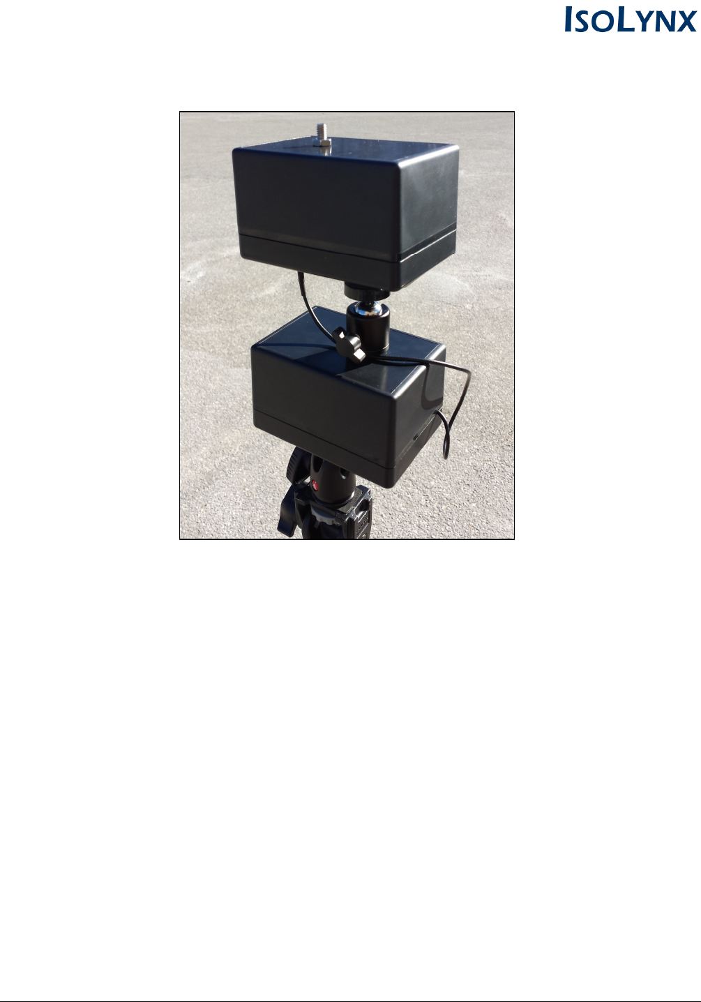
IsoLynx Reference Node
The reference node receives real-time UWB pings from tags attached to athletes and other objects of
interest, which are used to calculate the real-time location data. The reference node is capable of
receiving real-time data from UWB tags or interfacing with other reference nodes placed around the
playing surface in order to calculate live movement and position data. The reference node is a
standard USB device and can receive power from a PC/laptop, USB hub, USB battery pack, etc.
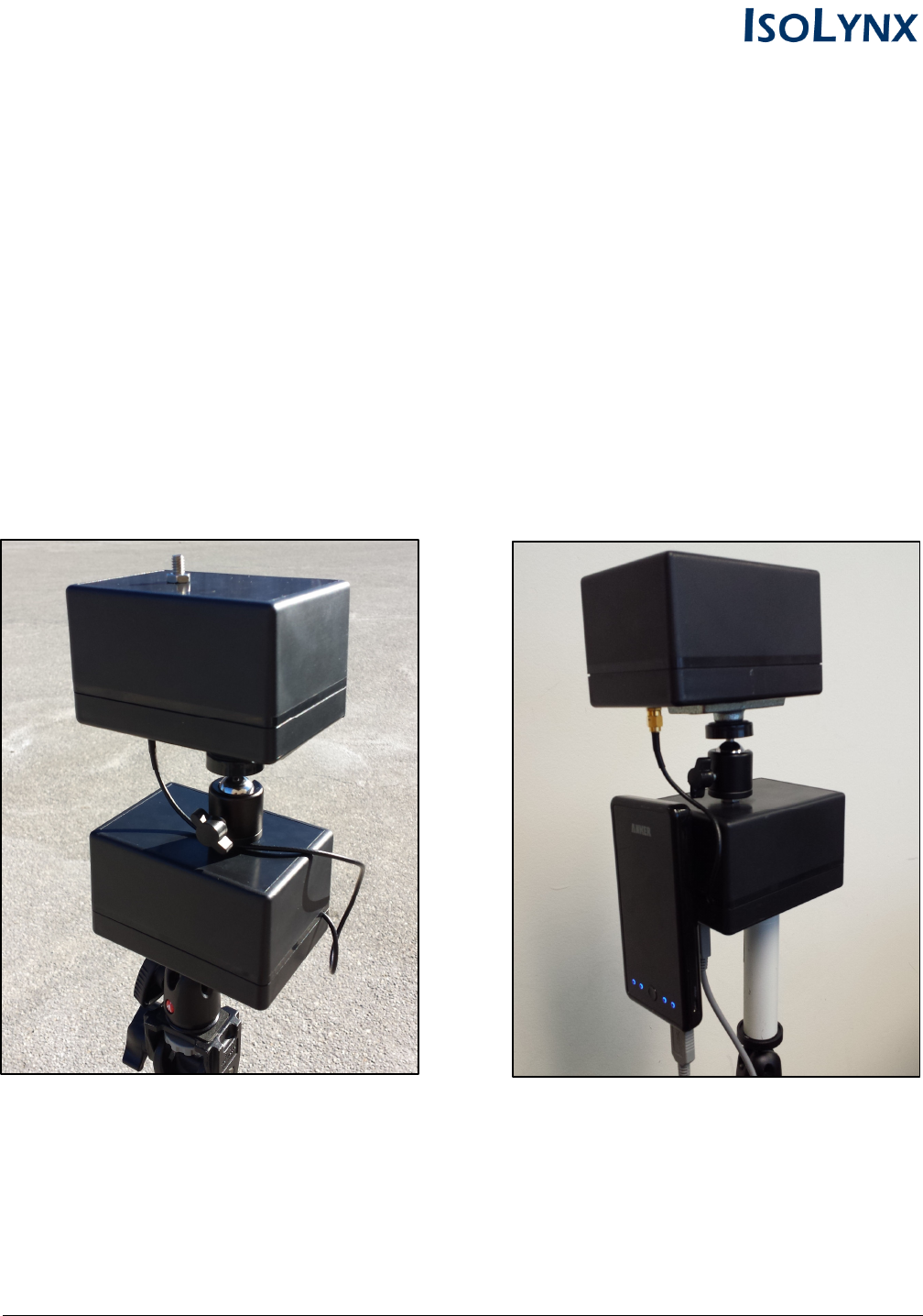
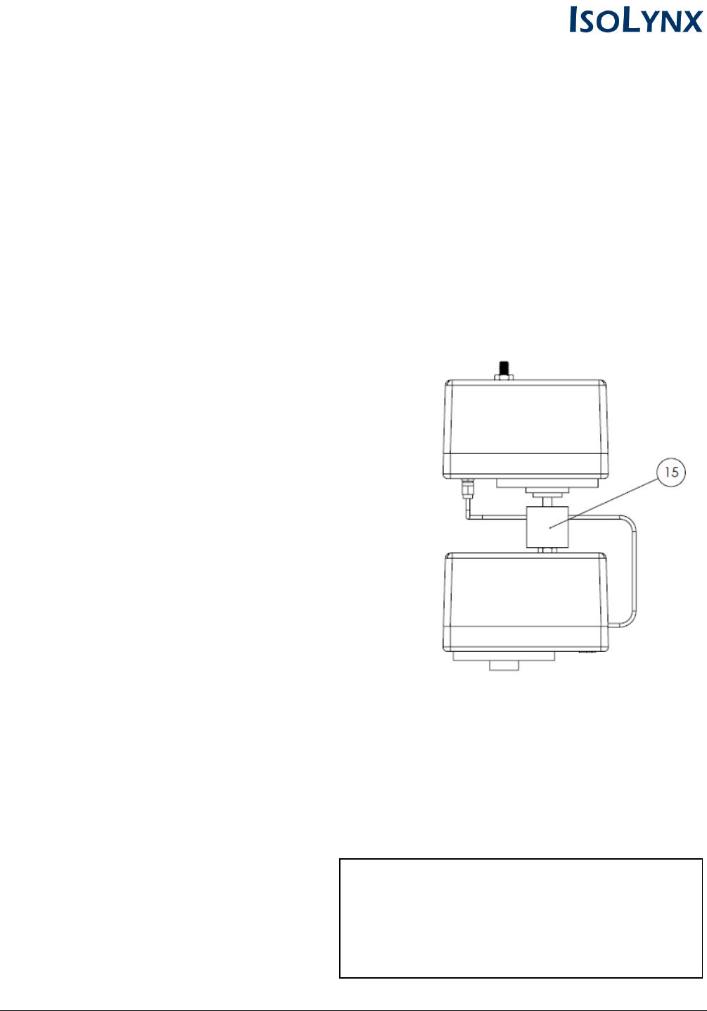
Mounted Reference Node Housing Node with Sample 3rd-Party Battery Pack
IsoLynx Reference Node - 2AHCQ-IL0201 5
Sample American Football Venue Setup
The steps below provide an example for setting up IsoLynx II reference nodes at an American Football
venue. The sample venue uses 8 reference nodes placed evenly around the perimeter of the field.
Mounting And Placement of Portable Reference Nodes
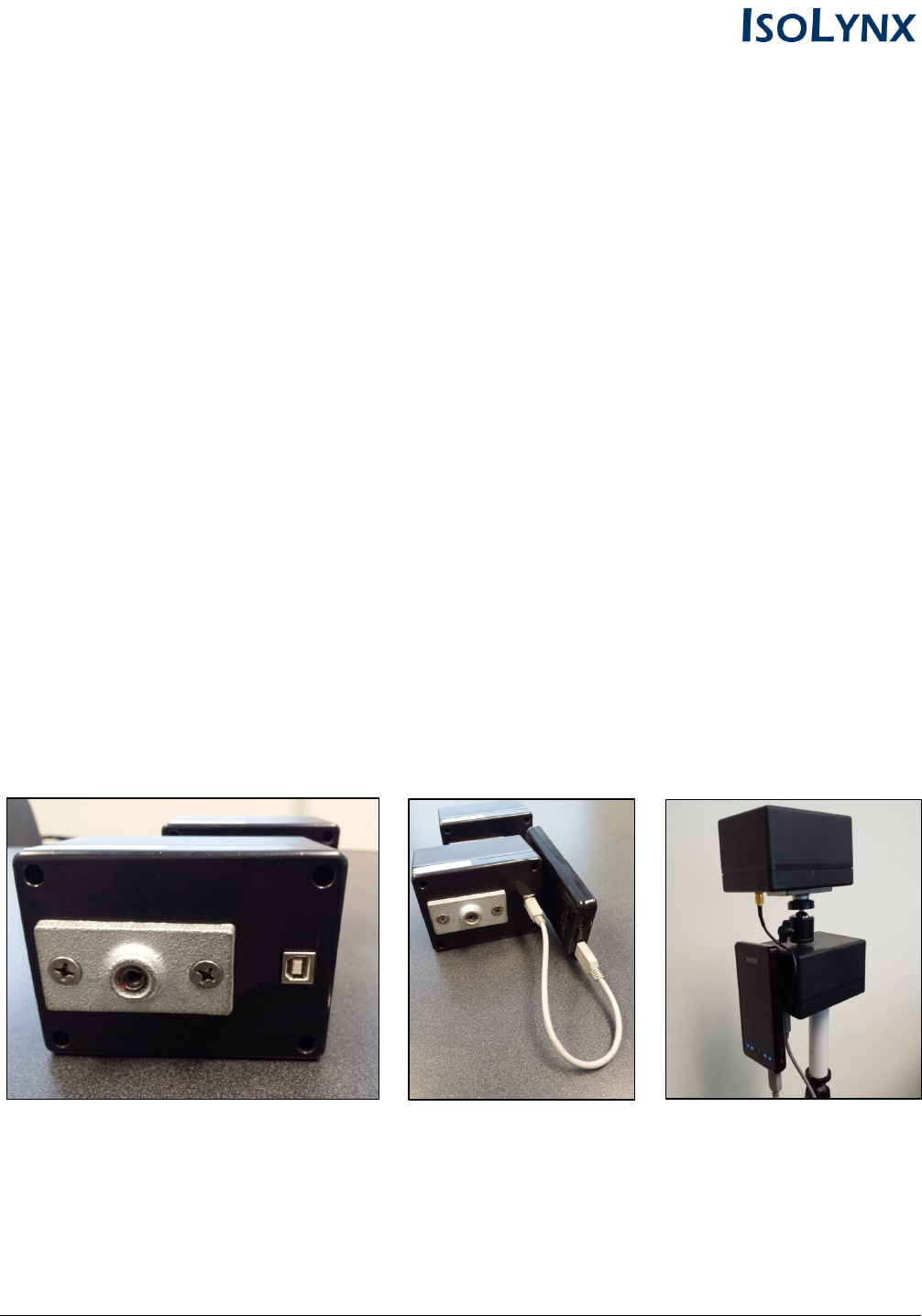
Attaching a USB Power Source
IsoLynx Reference Nodes are a standard USB device and will run on any USB power source.
Example 1 shows how to attach a third-party USB battery pack (not included) to power the reference
node during a game. An external USB battery pack can power the reference node continuously for
several days and is more than sufficient for a temporary setup like a football game. However, any USB
power source will work and we recommend finding the most appropriate USB solution for your needs.
Example 1: Attaching a USB Battery Pack (Not Included)
1. Ensure the battery pack is fully charged
2. Insert the battery pack USB cord into the bottom of the reference node
3. Attach the battery pack to the back of the unit using velcro
IsoLynx Reference Node - 2AHCQ-IL0201 6
Mounting the Reference Nodes to Portable Tripods
1. Attach the IsoLynx reference node to the tripod by screwing it on to the geared tripod head.
Ensure the reference node is fastened securely the tripod.
2. Extend the tripod to its full height and repeat steps 1 and 2 until all 8 reference nodes are ready
for placement around the field.
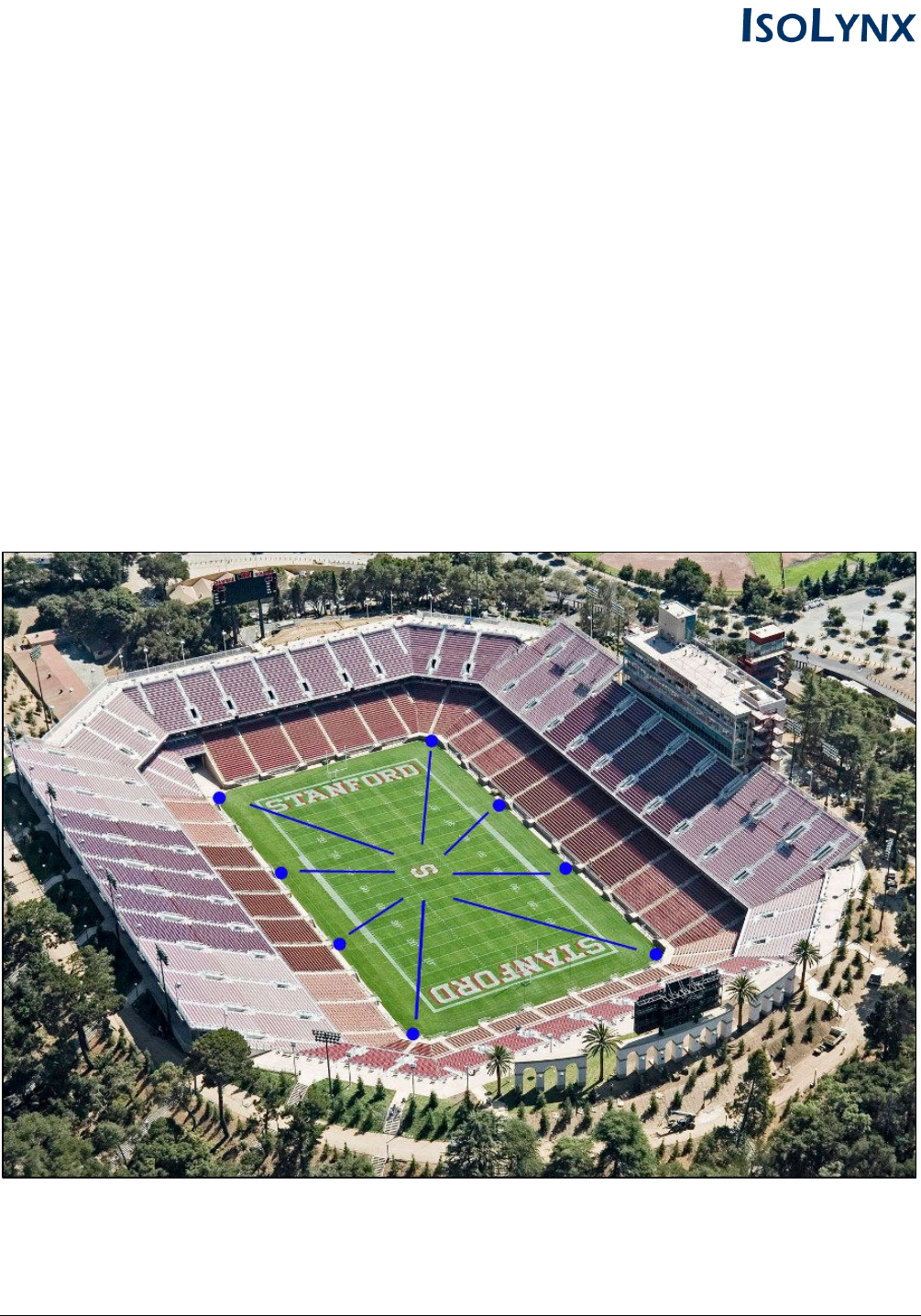
Placement and Aim of the Reference Nodes
Once attached to the tripods, the reference nodes should be evenly placed around the perimeter of
the playing surface and aimed toward the center of the venue (e.g.; the middle of the field at the 50-
yard). Ensure the tripods are set back at least 10 yards from the boundaries to prevent interference by
athletes or bystanders. See the image below for an example of the placement and aim of the
reference nodes during a football game.
IsoLynx Reference Node - 2AHCQ-IL0201 7
Dismantling The Reference Nodes After Use
The IsoLynx reference nodes are designed to be easily dismantled and powered-down after use. To
remove the IsoLynx hardware after a game, complete the following steps:
1. Power down the reference node by disconnecting the USB power source from the node
2. Detach the reference node housing from the tripod
3. Repeat steps 1 and 2 for all remaining reference nodes at the venue
IsoLynx Reference Node Hardware Specifications
Main System Components
Microcontroller: ATSAM4S4AA-MU
Power: USB 2.0 (5V)
Operating Voltage: 3.3V
Operating Current: 20mA (nominal)
Temperature Range: -40 - 85C
Mechanical
Height: 8.0"
Width: 3.25"
Depth: 5.5"
Weight: 0.59 kg
RF Characteristics
UWB IEEE802.15.4-2011 UWB Channel: 5
Bandwidth (Values in GHz):
fM The highest emission peak 6.7388
fL 10 dB below the highest peak 6.1414
fH 10 dB above the highest peak 6.8347
Bandwidth Calculated: (fH - fL) 0.6933
TX Antenna: 0 dBi Omnidirectional
RX Antenna: 10dBi Directional
Model
: IL0201
FCC ID: 2AHCQ-IL0201
This device complies with Part 15 of the FCC Rules.
Operation is subject to the following two conditions:
1. This device may not cause harmful interference.
2. This device must accept any interference received,
including interference that may cause undesired operation.