Itron 100GDLC AMR transceiver device for utility meters User Manual 100G Datalogging Installation Guide Direct Mount
Itron, Inc. AMR transceiver device for utility meters 100G Datalogging Installation Guide Direct Mount
Itron >
Contents
- 1. Users Manual Part 1
- 2. Users Manual Part 2
- 3. Users Manual Part 3
Users Manual Part 1

Natural Gas Solutions
100G Datalogging Installation Guide -
Direct Mount

100G Datalogging Installation Guide - Direct Mount ii
Identification
100G Datalogging Installation Guide - Direct Mount
03/6/2009 TDC-0823-000
Endpoint Part Numbers: 100G Endpoint: ERG-5000-001, ERG-5000-002, ERG-5000-003, ERG-5000-004, ERG-5000-005, ERG-5000-006, ERG-5000-007, ERG-5000-008
100G Datalogging Endpoint: ERG-5002-001, ERG-5002-002, ERG-5002-003, ERG-5002-004, ERG-5002-005, ERG-5002-006, ERG-5002-007, ERG-5002-008
Copyright
© 2009 Itron, Inc. All rights reserved.
Applicable Patents
U.S. Patent Numbers: 4,614,945; 4,753,169; 4,768,903; 4,799,059; 4,867,700
Canadian Patent Numbers: 1,254,949; 1,267,936; 1,282,118
Compliance Statement
This device complies with Part 15 of the FCC Rules. Operation of this device is subject to the following two conditions:
• This device may not cause harmful interference.
• This device must accept any interference that may cause undesirable operation.
This device must be permanently mounted such that it retains a distance of 20 centimeters (7.9 inches) from all persons in order to comply with FCC RF exposure levels.
Compliance Statement
This equipment has been tested and found to comply with the limits, pursuant to Part 15 of the FCC Rules. These limits are designed to provide reasonable protection against harmful
interference in a residential installation. Operation is subject to the following conditions:
• This device may not cause interference.
• This device must accept any interference that may cause undesired operation of the device.
Compliance Statement
This equipment complies with policies RSS-210 and RSS-GEN of the Industry Canada rules. Operation is subject to the following two conditions: (1) this device may not cause
interference, and (2) this device must accept any interference, including interference that may cause undesired operation of the device.
Trademark Notice
Itron and Endpoint-Link are registered trademarks of Itron, Inc.
All other product names and logos in this documentation are used for identification purposes only and may be trademarks or registered trademarks of their respective companies.
Suggestions
If you have comments or suggestions on how we may improve this documentation, send them to TechnicalCommunicationsManager@itron.com
If you have questions or comments about the software or hardware product, contact Itron Technical Support:
Contact
• Mail: Itron, Inc. Attention: Customer Care, 2111 N Molter Road, Liberty Lake, WA 99019
• Internet: www.itron.com
• E-mail: support@itron.com
• Phone: 1 800 635 8725
WARNING! Follow these procedures to avoid injury to yourself or others:
•The lithium battery may cause a fire or chemical burn if it is not disposed of properly.
•Do not recharge, disassemble, heat above 100° Celsius (212° Fahrenheit), or incinerate
the lithium battery.
•Keep the lithium battery away from children.
•Replace the lithium battery only with batteries meeting Itron specifications. Any other battery
may cause a fire or explosion.
WARNING! Only authorized Itron personnel should attempt repairs on Itron equipment.
Attempts to do so by others might void any maintenance contract with your company.
Unauthorized service personnel might also be subject to shock hazard on some Itron equipment
if removal of protective covers is attempted.
WARNING! To prevent ignition of flammable or combustible atmospheres, disconnect power
before servicing.
WARNING!
Substitution of components may impair intrinsic safety.

100G Datalogging Installation Guide - Direct Mount iii
Transportation Classification
The Federal Aviation Administration prohibits operating transmitters and receivers on all commercial aircraft. When powered, the 100G Datalogging Endpoint is considered an operating
transmitter and receiver and cannot be shipped by air. All product returns must be shipped by ground transportation.
Modifications and Repairs
To ensure system performance, this device and antenna shall not be changed or modified without the expressed approval of Itron. Any unauthorized modification will void the user's
authority to operate the equipment.
Meter Installation/Removal
In the event of malfunction, all repairs should be performed by Itron. It is the responsibility of users requiring service to report the need for service to Itron.

100G Datalogging Installation Guide - Direct Mount iv
Document Conventions
The following documentation conventions are used:
CAUTION! This type of note warns the user that failure to heed the
information in the note could result in loss of data. Be sure to carefully
read a CAUTION note and heed the advice/instructions.
WARNING! This type of note is used to warn of potential physical harm
to the user or hardware. It is critical that you pay strict attention to
WARNING notes, read the information carefully, and heed the advice,
instructions.
This type of note provides the user with extra hints/tips to make a task
easier to perform or a concept easier to understand.
This type of note supplies generic information to the user. The
information could be ignored and the user could still continue with a task
without suffering any adverse consequences.

100G Datalogging Installation Guide - Direct Mount v
Chapter 1 100G Datalogging Gas Endpoint ................................................................ 1
Transmission Modes ........................................................................................................................... 1
Specifications ...................................................................................................................................... 2
Related Documents .................................................................................................................. 2
Meter Compatibility List ....................................................................................................................... 2
Installation Prerequisites ..................................................................................................................... 8
Chapter 2 Elster American Meter Installation ........................................................... 11
Programming the 100G Datalogging Gas Endpoint Assembly ......................................................... 16
Attaching the 100G Datalogging Gas Endpoint Assembly to the Elster American Meter ................. 18
Chapter 3 Sensus/Rockwell Meter Installation ......................................................... 21
Programming the 100G Datalogging Gas Endpoint Assembly ......................................................... 25
Attaching the 100G Datalogging Gas Endpoint Assembly to the Sensus Meter .............................. 27
Chapter 4 Itron/Actaris Meter Installation ................................................................. 31
Programming the 100G Datalogging Gas Endpoint Assembly ......................................................... 34
Attaching the 100G Datalogging Gas Endpoint Assembly to the Itron/Actaris Meter ....................... 36
Attaching the 100G Datalogging Gas Endpoint Assembly to Flat-faced Itron/Actaris Meters 39
Securing Brass Meter Tags to Flat-faced Meters ................................................................... 43
Chapter 5 National/Lancaster Meter Installation ...................................................... 47
Programming the 100G Datalogging Gas Endpoint Assembly ......................................................... 53
Attaching the 100G Datalogging Gas Endpoint Assembly to the National/Lancaster Meter ............ 55
Chapter 6 Elster American and Itron Actaris Commercial Meter Installation ........ 57
Removing the Index/ Index Assembly from the Meter ...................................................................... 58
Programming the 100G Datalogging Commercial Gas Endpoint ..................................................... 60
Installing the 100G Datalogging Commercial Gas Endpoint on an Itron/Actaris Commercial Meter 67
Chapter 7 Sensus/Rockwell Commercial Meter Installation ................................... 73
Removing the Index/ Index Assembly from the Meter ...................................................................... 73
Programming the 100G Datalogging Gas Endpoint .......................................................................... 74
Attaching the 100G Datalogging Commercial Endpoint to a Sensus/Rockwell Commercial
Diaphragm Meter ............................................................................................................................... 76
Contents

Contents
vi 100G Datalogging Installation Guide - Direct Mount
Chapter 8 Dresser ROOTS Commercial Rotary Meter Installation ......................... 81
Installation Prerequisites ......................................................................................................... 81
Installation Examples .............................................................................................................. 82
Programming the 100G Datalogging Gas Endpoint Assembly ......................................................... 83
B3, LMMA, and S3A CTR/TC Dresser ROOTS Series Register Settings and Direct Drive
Programming Information .................................................................................................................. 85
B3, LMMA and S3A CTR/TC Meter Drive Rates: Residential Direct Drive Programming* ... 87
Installing the Residential 100G Datalogging Gas Endpoint Assembly to the Dresser
ROOTS Rotary Meter ........................................................................................................................ 89
Installing the 100G Datalogging Commercial Gas Endpoint on a Dresser ROOTS Rotary Meter ... 90
Programming the 100G Datalogging Commercial Gas Endpoint Assembly .......................... 91
B3, LMMA, and S3A CD/TD Dresser ROOTS Series Meter Drive Rates .............................. 93
To Attach the 100G Datalogging Commercial Gas Endpoint to the Meter ............................. 95
Completed Installation Examples ............................................................................................ 97

100G Datalogging Installation Guide - Direct Mount 1
Itron 100G Datalogging Gas Endpoints are radio-frequency (RF) devices designed to
transmit meter data to an RF meter reading device within transmission distance of the
endpoint. 100G Datalogging Gas Endpoints have the same increased output power as the
first generation 100G Gas Endpoints for greater RF transmission distance. The 100G direct-
mount endpoint reads and transmits a Standard Consumption Message (SCM) with
magnetic-tamper and tilt-tamper data. The Itron 100G Datalogging direct-mount endpoint
adds functionality by storing up to 40 days of hourly data.
This installation guide provides step-by-step instructions for installing the 100G Gas
Endpoint and the 100G Datalogging Gas Endpoint on a wide variety of meters. This
installation guide refers to both 100G endpoint versions as the 100G Datalogging Endpoint.
Mechanical installation procedures are identical for both modules. 100G Datalogging Gas
Endpoint compatible meters are listed in the Meter Compatibility List.
Transmission Modes
The 100G Datalogging Gas Endpoint transmits in one of three modes:
• Fixed Network Mode In this mode, a 100G Datalogging Gas Endpoint transmits a
high-powered RF message every 60 seconds. Output power in this mode is 250
milliwatts or +24dBm; expected battery life is 20 years.
• Mobile and Handheld Mode In this mode, a 100G Datalogging Gas Endpoint
transmits a medium-powered RF message every 15 seconds. Output power in this
mode is 10 milliwatts or +10dBm; expected battery life is 20 years.
• (Optional) Hard to Read Mobile and Handheld Mode In this mode, a 100G
Datalogging Gas Endpoint transmits a high-powered RF message every 30 seconds.
Output power in this mode is 250 milliwatts or +24dBm; expected battery life
decreases to 15 years in this mode. The Hard to Read Mobile and Handheld Mode
should only be used for exceptionally hard-to-read applications (such as meters
installed on roof tops or in sub-basements).
An FCC license is not required to read 100G Datalogging Gas Endpoint.
C
HAPTER
1
100G Datalogging Gas Endpoint

Chapter 1 100G Datalogging Gas Endpoint
2 100G Datalogging Installation Guide - Direct Mount
Specifications
Functional Specifications Description
Power Source
100G
100G Datalogging
Two "A" cell lithium batteries
One "A" cell lithium battery
Tamper Detection Tilt tamper and magnetic tamper
FCC Compliance Part 15 certified
Industry Canada Compliance RSS-210 certified
Intrinsically Safe per UL Class I, Division 1, Groups C and D
Product Identification Numeric and barcoded endpoint type and serial number
Construction Materials Gray polycarbonate housing and back plate with
encapsulated electronics
Operational Specifications Description
Operating Temperatures -40° to 158° F (-40° to +70° C)
Operating Humidity 5 to 95 percent relative humidity
Program Frequency 908 MHz
Transmit Frequency Spread spectrum 908 to 924 MHz ISM band
Data Integrity Verified in every data message
Related Documents
Document Title Document Part Number
Gas Endpoint Meter Compatibility List PUB-0117-002
Gas Endpoint Ordering Guide PUB-0117-001
100G Datalogging Specification Sheet Publication 100941SP-01
Endpoint Link® Programming Guide TDC-0744
Meter Compatibility List
The Meter Compatibility table lists meters compatible with the 100G Datalogging Gas
Endpoint. Due to continuous research, product improvements, and enhancements, Itron
reserves the right to change this list without notice.
Note On rare occasions the location of endpoint-to-meter mounting holes on
older diaphragm gas meters might not match up with the mounting holes on the
100G Datalogging Gas Endpoint. This can prevent the 100G Datalogging Gas
Endpoint from properly mounting to the meter.

Meter Compatibility List
100G Datalogging Installation Guide - Direct Mount 3
100G Series Meter Compatibility List
Mfg. Model Description Class Comments Endpoint
Type Endpoint
Part No.
Elster American/
Canadian
W75AL Residential Aluminum case meters
only 100G
100G Datalogging
ERG-5000-001
ERG-5002-001
Elster American/
Canadian
AL-175 Residential Aluminum case meters
only 100G
100G Datalogging
ERG-5000-001
ERG-5002-001
Elster American/
Canadian
AT-175 Residential Aluminum case meters
only 100G
100G Datalogging
ERG-5000-001
ERG-5002-001
Elster American/
Canadian
ALC-175 Residential Aluminum case meters
only 100G
100G Datalogging
ERG-5000-001
ERG-5002-001
Elster American/
Canadian
AT-210 Residential Aluminum case meters
only 100G
100G Datalogging
ERG-5000-001
ERG-5002-001
Elster American/
Canadian
AL-225 Canada only Residential Aluminum case meters
only 100G
100G Datalogging
ERG-5000-001
ERG-5002-001
Elster American/
Canadian
AL-250 Residential Aluminum case meters
only 100G
100G Datalogging
ERG-5000-001
ERG-5002-001
Elster American/
Canadian
AR-250 Residential Aluminum case meters
only 100G
100G Datalogging
ERG-5000-001
ERG-5002-001
Elster American/
Canadian
AC-250 Residential Aluminum case meters
only 100G
100G Datalogging
ERG-5000-001
ERG-5002-001
Elster American/
Canadian
AM-250 Residential Aluminum case meters
only 100G
100G Datalogging
ERG-5000-001
ERG-5002-001
Elster American/
Canadian
AL-310 Residential Aluminum case meters
only 100G
100G Datalogging
ERG-5000-001
ERG-5002-001
Elster American/
Canadian
AL-350 Residential Aluminum case meters
only 100G
100G Datalogging
ERG-5000-001
ERG-5002-001
Elster American/
Canadian
AT-350 Residential Aluminum case meters
only 100G
100G Datalogging
ERG-5000-001
ERG-5002-001
Elster American/
Canadian
AL-425 Residential Aluminum case meters
only 100G
100G Datalogging
ERG-5000-001
ERG-5002-001
Elster American/
Canadian
AC-630 Residential Aluminum case meters
only 100G
100G Datalogging
ERG-5000-001
ERG-5002-001
Elster American/
Canadian
5B 225 Aluminum case Residential 100G
100G Datalogging
ERG-5000-001
ERG-5002-001
Elster American/
Canadian
35B Iron case Commercial 100G ERG-5000-007
Elster American/
Canadian
60B Iron case Commercial 100G
ERG-5000-007
Elster American/
Canadian
80B Iron case Commercial Must have front reading
index.
100G
ERG-5000-007
Elster American/
Canadian
250B Iron case Commercial 100G
ERG-5000-007
Elster American/
Canadian
500B Iron case Commercial 100G
ERG-5000-007
Elster American/
Canadian
AL800 Commercial Aluminum case meters
only
100G
ERG-5000-007

Chapter 1 100G Datalogging Gas Endpoint
4 100G Datalogging Installation Guide - Direct Mount
Mfg. Model Description Class Comments Endpoint
Type Endpoint
Part No.
Elster American/
Canadian
AL1000 Commercial Aluminum case meters
only
100G
ERG-5000-007
Elster American/
Canadian
AL1400 Commercial Aluminum case meters
only
100G
ERG-5000-007
Elster American/
Canadian
AL2300 Commercial Aluminum case meters
only
100G
ERG-5000-007
Elster American/
Canadian
AL3000 Commercial Aluminum case meters
only
100G
ERG-5000-007
Elster American/
Canadian
AL5000 Commercial Aluminum case meters
only
100G
ERG-5000-007
Sensus/Invensys/
Equimeter/Rockwell
R-175 11-tooth Residential 24- and 30-tooth gears
are not compatible.
100G
100G Datalogging
ERG-5000-002
ERG-5002-002
Sensus/Invensys/
Equimeter/Rockwell
R-200 11-tooth Residential 100G
100G Datalogging
ERG-5000-002
ERG-5002-002
Sensus/Invensys/
Equimeter/Rockwell
RT-200 11-tooth Residential 100G
100G Datalogging
ERG-5000-002
ERG-5002-002
Sensus/Invensys/
Equimeter/Rockwell
RC-225 11-tooth
(Canada only)
Residential 100G
100G Datalogging
ERG-5000-002
ERG-5002-002
Sensus/Invensys/
Equimeter/Rockwell
RT-230 11-tooth Residential 100G
100G Datalogging
ERG-5000-002
ERG-5002-002
Sensus/Invensys/
Equimeter/Rockwell
R-275 11-tooth Residential 24- and 30-tooth gears
are not compatible. 100G
100G Datalogging
ERG-5000-002
ERG-5002-002
Sensus/Invensys/
Equimeter/Rockwell
RT-275 11-tooth Residential 100G
100G Datalogging
ERG-5000-002
ERG-5002-002
Sensus/Invensys/
Equimeter/Rockwell
R-315 11-tooth Residential 24- and 30-tooth gears
are not compatible. 100G
100G Datalogging
ERG-5000-002
ERG-5002-002
Sensus/Invensys/
Equimeter/Rockwell
250 11-tooth Residential 24- and 30-tooth gears
are not compatible. 100G
100G Datalogging
ERG-5000-002
ERG-5002-002
Sensus/Invensys/
Equimeter/Rockwell
310 11-tooth Residential 100G
100G Datalogging
ERG-5000-002
ERG-5002-002
Sensus/Invensys/
Equimeter/Rockwell
S-110 11-tooth Residential 100G
100G Datalogging
ERG-5000-002
ERG-5002-002
Sensus/Invensys/
Equimeter/Rockwell
S-200 11-tooth Residential 100G
100G Datalogging
ERG-5000-002
ERG-5002-002
Sensus/Invensys/
Equimeter/Rockwell
175-S 18-tooth Residential 24- and 30-tooth gears
are not compatible. 100G
100G Datalogging
ERG-5000-004
ERG-5002-004
Sensus/Invensys/
Equimeter/Rockwell
RT-100 18-tooth Residential 24- and 30-tooth gears
are not compatible 100G
100G Datalogging
ERG-5000-004
ERG-5002-004
Sensus/Invensys/
Equimeter/Rockwell
S-190 18-tooth Residential 24- and 30-tooth gears
are not compatible. 100G
100G Datalogging
ERG-5000-004
ERG-5002-004

Meter Compatibility List
100G Datalogging Installation Guide - Direct Mount 5
Mfg. Model Description Class Comments Endpoint
Type Endpoint
Part No.
Sensus/Invensys/
Equimeter/Rockwell
S-120 11-tooth Residential 100G
100G Datalogging
ERG-5000-002
ERG-5002-002
Sensus/Invensys/
Equimeter/Rockwell
T-120 11-tooth Residential 100G
100G Datalogging
ERG-5000-002
ERG-5002-002
Sensus/Invensys/
Equimeter/Rockwell
T-110 11-tooth Residential 100G
100G Datalogging
ERG-5000-002
ERG-5002-002
Sensus/Invensys/
Equimeter/Rockwell
R-415 18-tooth Residential Older meters may have
endpoint-to-meter
mounting hole variations
that can make them
incompatible.
100G
100G Datalogging
ERG-5000-004
ERG-5002-004
Sensus/Invensys/
Equimeter/Rockwell
RT-360 18-tooth Residential 100G
100G Datalogging
ERG-5000-004
ERG-5002-004
Sensus/Invensys/
Equimeter/Rockwell
MR8
(R-275
Metric)
16-tooth Residential 100G
100G Datalogging
ERG-5000-003
ERG-5002-003
Sensus/Invensys/
Equimeter/Rockwell
MR12
(R-415
Metric)
16-tooth Residential 100G
100G Datalogging
ERG-5000-003
ERG-5002-003
Sensus/Invensys/
Equimeter/Rockwell
750 Commercial 100G ERG-5000-008
Sensus/Invensys/
Equimeter/Rockwell
1000 Commercial 100G ERG-5000-008
Sensus/Invensys/
Equimeter/Rockwell
1600 Commercial 100G ERG-5000-008
Sensus/Invensys/
Equimeter/Rockwell
3000 Commercial Vertical index only 100G ERG-5000-008
Sensus/Invensys/
Equimeter/Rockwell
5000 Commercial Vertical index only 100G ERG-5000-008
Sensus/Invensys/
Equimeter/Rockwell
10000 Commercial Vertical index only 100G ERG-5000-008
National/ Lancaster 175 Residential Actaris/Schlumberger/
Sprague direct-read
(odometer) indexes
cannot be used.
100G ERG-5000-006
National/ Lancaster U175 UL175 Residential Actaris/Schlumberger/
Sprague direct-read
(odometer) indexes
cannot be used.
100G ERG-5000-006
National/ Lancaster 250 Residential Actaris/Schlumberger/
Sprague direct-read
(odometer) indexes
cannot be used.
100G ERG-5000-006
Itron/Actaris/
Schlumberger/
Sprague
175 3-hole index box Residential Index boxes with 3
mounting holes 100G ERG-5000-005
Itron/Actaris/
Schlumberger/
Sprague
175 WC 3-hole index box Residential Index boxes with 3
mounting holes 100G ERG-5000-005

Chapter 1 100G Datalogging Gas Endpoint
6 100G Datalogging Installation Guide - Direct Mount
Mfg. Model Description Class Comments Endpoint
Type Endpoint
Part No.
Itron/Actaris/
Schlumberger/
Sprague
175
Combination
3-hole index box
Integrated
regulator
Residential Index boxes with 3
mounting holes 100G ERG-5000-005
Itron/Actaris/
Schlumberger/
Sprague
210 Residential
100G ERG-5000-005
Itron/Actaris/
Schlumberger/
Sprague
240 Canadian
Version of 250
Residential
100G ERG-5000-005
Itron/Actaris/
Schlumberger/
Sprague
240
Combination
Integrated
regulator
Residential
100G ERG-5000-005
Itron/Actaris/
Schlumberger/
Sprague
240 Residential
100G ERG-5000-005
Itron/Actaris/
Schlumberger/
Sprague
240 1-hole cover flat
face
Residential Requires Itron 1A
Adapter P/N
CFG-0015-001 Kit
100G ERG-5000-005
+ CFG-0015-001
Itron/Actaris/
Schlumberger/
Sprague
240 2-hole cover Residential
100G ERG-5000-005
Itron/Actaris/
Schlumberger/
Sprague
250 Residential
100G ERG-5000-005
Itron/Actaris/
Schlumberger/
Sprague
250 WC Residential
100G ERG-5000-005
Itron/Actaris/
Schlumberger/
Sprague
250
Combination
Integrated
regulator
Residential
100G ERG-5000-005
Itron/Actaris/
Schlumberger/
Sprague
1A Flat face
Includes 3-dial,
2cf indexes.
Residential Requires Itron 1A adapter
kit, CFG-0015-001
100G ERG-5000-005 +
CFG-0015-001
Itron/Actaris/
Schlumberger/
Sprague
METRIS 250 3-hole index box
Slant-faced
Residential Index boxes with 3
mounting holes
100G ERG-5000-005
Itron/Actaris/
Schlumberger/
Sprague
305
Combination
Integrated
regulator
Residential
100G ERG-5000-005
Itron/Actaris/
Schlumberger/
Sprague
400 Slant-faced Residential
100G ERG-5000-005
Itron/Actaris/
Schlumberger/
Sprague
400A Slant-faced Residential
100G ERG-5000-005
Itron/Actaris/
Schlumberger/
Sprague
675A Top-mount index Commercial Requires Itron/Actaris
adapter p/n 80005901-001;
purchase from
Itron/Actaris
100G ERG-5000-007
Itron/Actaris/
Schlumberger/
Sprague
800A Top-mount index Commercial Requires Itron/Actaris
adapter p/n 80005901-001;
purchase from
Itron/Actaris
100G ERG-5000-007

Meter Compatibility List
100G Datalogging Installation Guide - Direct Mount 7
Mfg. Model Description Class Comments Endpoint
Type Endpoint
Part No.
Itron/Actaris/
Schlumberger/
Sprague
1000A Top-mount index Commercial Requires Itron/Actaris
adapter p/n 80005901-001;
purchase from
Itron/Actaris
100G ERG-5000-007
EMCO #2 ½ Commercial 100G ERG-5000-008
EMCO #3 Commercial 100G ERG-5000-008
EMCO #4 Commercial 100G ERG-5000-008
EMCO #4 ½ Commercial 100G ERG-5000-008
EMCO #5 Commercial 100G ERG-5000-008
Dresser ROOTS Series B3
8C - 56M
8C - 16M
CTR
TC
(No pulser, No
instrument drive)
Commercial To attach an Elster
American endpoint,
install Dresser's Elster
American AMR adapter
kit.
100G
100G Datalogging
Dresser adapter
P/N 059599-000
ERG-5000-001
ERG-5002-001
Dresser ROOTS Series A1
(LMMA)
1.5M - 5M
CTR
(No pulser, No
instrument drive)
Commercial To attach an Elster
American endpoint,
install Dresser's Elster
American AMR adapter
kit.
100G
100G Datalogging
Dresser adapter
P/N 058530-610
ERG-5000-001
ERG-5002-001
Dresser ROOTS Series A1
(LMMA)
7M - 16M
CTR
(No pulser
No instrument
drive)
Commercial To attach an Elster
American endpoint,
install Dresser's Elster
American adapter kit.
100G
100G Datalogging
Dresser adapter
P/N 058531-610
ERG-5000-001
ERG-5002-001
Dresser ROOTS Series A1
(LMMA)
1.5M - 16M
TC
(No pulser
No instrument
drive)
Commercial To attach an Elster
American endpoint,
install Dresser's Elster
American AMR adapter
kit.
100G
100G Datalogging
Dresser adapter
P/N 058224-641
ERG-5000-001
ERG-5002-001
Dresser ROOTS 5C/8C15 Series Z compact
meter
Commercial To attach an Elster
American endpoint,
install Dresser's Elster
American adapter kit.
100G
100G Datalogging
Dresser adapter
P/N 059847-000
ERG-5000-001
ERG-5002-001
Dresser ROOTS B3/LMMA Instrument drive
CD/TD
Commercial Standard index drive and
no instrument.
100G ERG-5000-007
Chapter 1 100G Datalogging Gas Endpoint
8 100G Datalogging Installation Guide - Direct Mount
Installation Prerequisites
Prior to installation, verify you have the following items:
1. 100G Datalogging Gas Endpoints designed for your specific brand of residential or
commercial gas meters (endpoints include new tamper seals).
2. A compatible meter (see the Meter Compatibility List on page 2).
3. A compatible index. Itron 100G Datalogging Gas Endpoints are compatible with
standard dial and direct-read (odometer) indexes. Exceptions are noted on the Meter
Compatibility List on page 2.
4. Installation tools (provided by installer or customer)
• Small and medium flat-blade or Phillips screwdrivers - to remove and tighten
index and index-cover screws.
• Side-cutting plier/wire snips - to cut wire seals, if applicable.
• Small putty knife - residential meters.
• Meter seals, wire seal, and seal press - to protect the meter from tampering, if
applicable.
• 11/32-inch nut driver or other blunt tool - to securely seat new tamper plugs
over screw holes.
• FC200SR handheld computer with Endpoint-Link® or EndPoint-Link Pro®
software - to program and check 100G Datalogging Gas Endpoint installation
and operation.
Caution The 100G Datalogging Gas Endpoints can only be programmed using
FC200SR Handheld Computers loaded with EndPoint-Link® or EndPoint-Link Pro®
software version 5.3 or later.

Installation Prerequisites
100G Datalogging Installation Guide - Direct Mount 9
• Replacement screws - to mount the 100G Datalogging Gas Endpoint assembly
to the meter and the index to the endpoint housing:
Replacement Screws
Meter To mount the 100G
Datalogging Gas
Endpoint on the meter:
Itron Part
Number To mount the index on the
100G Datalogging Gas
Endpoint housing:
Itron Part
Number
Elster American 1/4 - 20 x 5/8" slotted,
Fillister head
8 - 32 x 3/16" slotted, round
pan-head
Sensus/Rockwell 10 - 24 x 5/8" slotted
Fillister head
6 - 32 x 5/8" slotted, round
pan-head
Itron/Actaris 10 - 24 x 5/8" slotted
Fillister head
10 - 24 x 1/4" slotted, round
pan-head
National/Lancaster 10 - 24 x 3/4" Phillips flat-
head stainless steel
SCR-0014-004 6 - 19 x 3/8" thread-forming,
Phillips pan-head to mount
indexes with legs
6 - 19 x 3/8" thread-forming,
Phillips, Fillister head to
mount indexes with screw
holes
SCR-0015-001
SCR-0037-001
Commercial
Meter To mount the 100G
Datalogging
Commercial endpoint
on the meter:
Itron Part
Number To mount the index (and
index assembly, if
applicable) on the 100G
Datalogging Commercial
endpoint housing:
Itron Part
Number
Elster American 2A x 3.25" length, slotted
round-head drilled to accept
utility-approved wire seals
SCR-0062-001
(Elster American)
12 - 24 x 1/2" slotted, Fillister
head machine screws, drilled
to accept utility-approved wire
seals
Sensus/Rockwell 2A x 3.63" length, slotted
round-head drilled to accept
utility-approved wire seals
SCR-0062-002 2A x 2.94" length, slotted
round-head
SCR-0062-003

Chapter 1 100G Datalogging Gas Endpoint
10 100G Datalogging Installation Guide - Direct Mount
100G Datalogging Installation Guide - Direct Mount 11
This chapter provides instructions to install the 100G Datalogging Gas Endpoint on an
Elster American Meter.
Installing the 100G Datalogging Gas Endpoint involves four tasks:
1. Removing the index from the meter.
2. Assembling the 100G Datalogging Gas Endpoint and index.
3. Programming the 100G Datalogging Gas Endpoint assembly.
4. Attaching the 100G Datalogging Gas Endpoint assembly to the meter.
Note Properly dispose all unused screws, old index covers, gaskets, tamper seals,
and other leftover materials. Do not leave materials on customer premises.
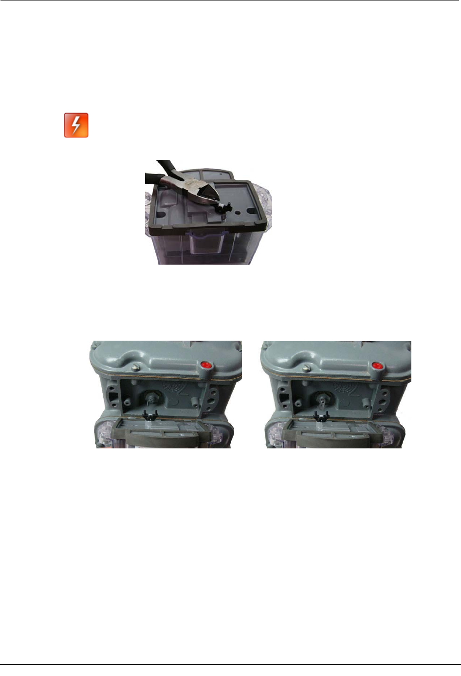
To remove the index from the meter
1. Remove the four index cover screws and the index cover from the Elster American
meter. Alternate screw removal following the numbered pattern in the photo.
C
HAPTER
2
Elster American Meter Installation
Chapter 2 Elster American Meter Installation
12 100G Datalogging Installation Guide - Direct Mount
2. Examine the mounting screws. If they are 5/8" long and not corroded, keep them to re-
attach the 100G Datalogging Gas Endpoint assembly. If the screws are not the correct
length or if the screws are corroded, discard.
Note You may use the removed index cover as a temporary storage container for
screws. Properly dispose all unused screws, old index covers, gaskets, tamper
seals, and other leftover materials. Do not leave materials on customer premises.
3. Unscrew one index mounting screw completely. Hold one hand under the index to
catch the screw. While removing the other mounting screw, pull the index away from
the meter to keep the index backplate against the back of the screw. Remove the screw
completely after the index is free of the meter.
Set the index aside where it will not be damaged or fill with dirt, rain or snow. The
index will be mounted to the endpoint later in this procedure. Verify the index
mounting screws are 3/16" long and not corroded. If the screws are the correct length
and not corroded, retain for later use. If the original screws were discarded, use the
correct replacement screws (see Installation Prerequisites on page 8.)
4. Remove the old gasket, gasket residue and dirt from the meter (if applicable). The
meter face must be free of gasket residue before you install the 100G Datalogging Gas
Endpoint.
Installation Prerequisites
100G Datalogging Installation Guide - Direct Mount 13
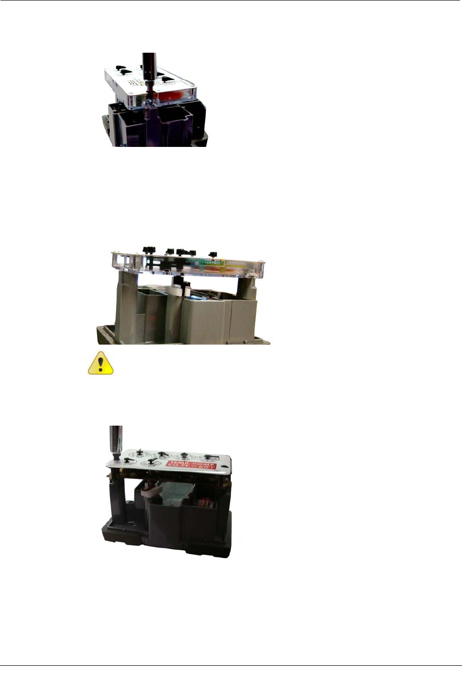
To Assemble the 100G Datalogging Gas Endpoint and Index
1. Separate the 100G Datalogging Gas Endpoint housing from the cover by pulling the
cover straight out from the housing.
2. Set the endpoint cover aside where it will not be damaged or fill with rain, dirt or
snow. The cover will be used later in this installation procedure.
Chapter 2 Elster American Meter Installation
14 100G Datalogging Installation Guide - Direct Mount
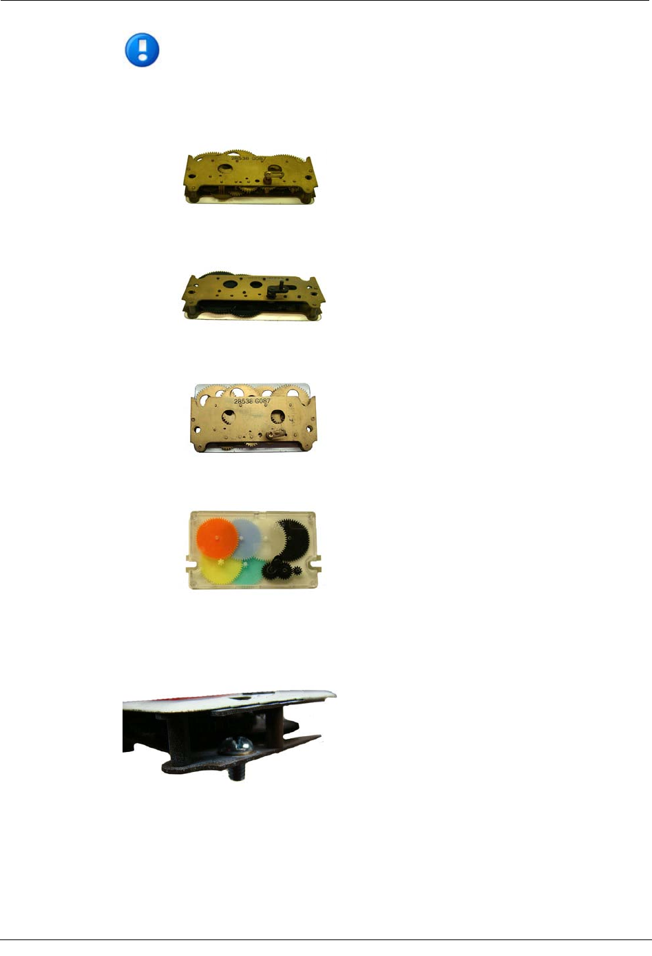
Note Elster American meter indexes are available in different models:
Index wrigglers on one-foot meters
with drive slots
Index meters on two-foot meters
with drive posts
An Elster American index with
mounting screw holes
An Elster American index with
mounting slots
If your index has mounting screw slots, skip steps 3 and 4. If your index has mounting
screw holes, perform steps 3 and 4, and skip steps 5 and 6.
3. Using the original index mounting screw or a replacement screw, if necessary, place
one 8 - 32 3/16" screw into the index's right-hand mounting screw hole.
Installation Prerequisites
100G Datalogging Installation Guide - Direct Mount 15
4. Attach the screw to the endpoint housing's right-index mounting post just enough to
hold the screw and the right end of the index in place.
5. Screw one 8 - 32 x 3/16" screw into the right index mounting post one or two turns.
Do not tighten the screw.
6. Place the right index mounting screw slot under the screw head. Do not tighten the
screw.
7. Slide the index drive post into the endpoint wriggler. Verify positive engagement.
Caution If the index wriggler has a drive slot, place the endpoint wriggler's drive
post into the index drive slot. Failure to mate the endpoint wriggler with the index
drive post (or slot) can cause binding and lead to poor registration or meter failure.
8. Install and tighten the left index mounting screw (for indexes with either mounting
screw slots or holes). Tighten the right index mounting screw.
Chapter 2 Elster American Meter Installation
16 100G Datalogging Installation Guide - Direct Mount
9. Slide the endpoint cover over the index and housing. Verify the cover is installed
correctly. The endpoint label should be clearly visible and easily read.
Programming the 100G Datalogging Gas Endpoint Assembly
The 100G Datalogging Gas Endpoint must be programmed with the FC200SR
handheld computer loaded with EndPoint-Link® or Point-Link Pro® software version
5.3 or later. See the Endpoint-Link v5.3 (or later) Endpoint Programming Guide
(TDC-0744) for more complete programming information.
Caution The 100G Datalogging Gas Endpoint must be programmed before use.
Follow the steps in this section to properly program the endpoint.
Programming the 100G Datalogging Gas Endpoint Assembly
100G Datalogging Installation Guide - Direct Mount 17
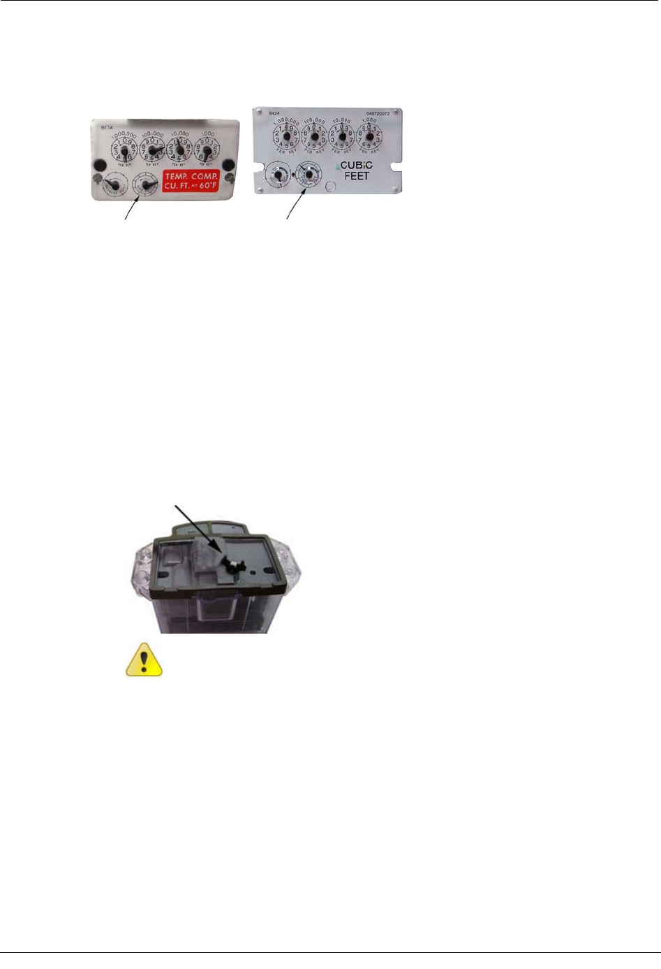
The endpoint is programmed based on the meter's drive rate. Take note of the index drive
rate shown on a lower left dial on the index. The endpoint is programmed based on the drive
rate. Elster American meter index drive rates are either 1-cubic foot or 2-cubic feet.
To Program the 100G Datalogging Gas Endpoint
1. Program the meter drive rate into the 100G Datalogging Gas Endpoint using the
FC200SR. For all programming and "Check Endpoint" operations, hold the FC200SR
as close to vertical as possible. For best success, keep the FC200SR within 6 feet of
the target endpoint. Verify you have the correct programming mode (Fixed Network
Mode, Mobile/Handheld Mode, or Hard to Read Mobile/Handheld Mode) for your
application. Programming parameters are based on the mode defined by your system
administrator.
During programming, the 100G Datalogging Gas Endpoint is set to the nearest 100
cubic feet; the last two digits (tens and units) are programmed as zeros (0). After
programming is complete, the endpoint assembly will read to the nearest cubic foot.
2. Slowly turn the endpoint's drive wriggler two turns in the direction shown on the
index drive rate. This verifies the endpoint is counting properly after assembly.
Caution Do not turn the drive wriggler faster than one turn per second.
3. Read the 100G Datalogging Gas Endpoint using the FC200SR.
• If the read result is higher than the number programmed in Step 1, the 100G
Datalogging Gas Endpoint is counting correctly.
• If the read result is not higher than the number programmed in Step 1, replace
the 100G Datalogging Gas Endpoint.
Chapter 2 Elster American Meter Installation
18 100G Datalogging Installation Guide - Direct Mount
Attaching the 100G Datalogging Gas Endpoint Assembly to
the Elster American Meter
After 100G Datalogging Gas Endpoint programming is complete, attach the endpoint
assembly to the Elster American Meter.
Warning For 5B Meters only: If the 100G Datalogging Gas Endpoint
will be installed on a 5B-225 aluminum meter, cut 1/16" off each
endpoint wriggler post to prevent the wriggler from rubbing on the face
of the nut holding the meter drive dog in place.
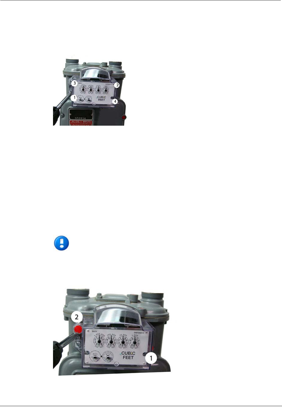
To Attach the 100G Datalogging Gas Endpoint
1. Align the endpoint wriggler to connect with the drive post (or slot) of the meter.
For one-foot meters: Align the endpoint assembly wriggler perpendicular to the meter
drive post.
For two-foot meters: Align the endpoint assembly wriggler perpendicular to the meter
drive slot. The pin on the endpoint wriggler may be installed inside or outside the
meter drive slot. For easy assembly, Itron recommends installing the pin on the 100G
Datalogging Gas Endpoint wriggler outside the meter drive slot.
Attaching the 100G Datalogging Gas Endpoint Assembly to the E
lster American Meter
100G Datalogging Installation Guide - Direct Mount 19
2. Carefully align the endpoint's four screw holes with the holes on the meter. Attach
using the original mounting screws if they are the correct size and are not corroded
(1/4 - 20 x 5/8" screws.) If the original screws were discarded, use the correct
replacement screws (see Installation Prerequisites on page 8). Tighten in an
alternating, diagonal pattern as shown in the photo:
• Insert first screw and tighten 1/4 to 1/2 turn after the screw contacts the meter
connection.
• Insert the second screw and tighten 1/4 to 1/2 turn after contact with the meter
connection.
• Insert the third screw and tighten 1/4 to 1/2 turn after contact with the meter
connection.
• Insert the last screw and tighten 1/4 to 1/2 turn after contact with the meter
connection.
Return to the first screw and tighten. Continue with the second, third and last screw
until all screws are tight. Use equal screw tension to tighten each screw.
Note Meter manufacturers should torque the mounting screws 15 to 20 inch-
pounds.
3. Place new tamper seals over the two screws with tamper seal mounts. Press tamper
seals into place using the 11/32" nut driver or similar blunt tool.
Chapter 2 Elster American Meter Installation
20 100G Datalogging Installation Guide - Direct Mount
4. Complete necessary paperwork and verify all excess materials are removed from the
customer's premises. 100G Datalogging Gas Endpoint installation on the Elster
American meter is complete.