Itron 100GDLRN AMR Transceiver device for utility meters User Manual 1
Itron Inc AMR Transceiver device for utility meters Users Manual 1
Itron >
Contents
- 1. Users Manual 1
- 2. Users Manual 2
Users Manual 1

Natural Gas Solutions
100G Datalogging FN ERT Module Installation
Guide - Remote Mount
TDC-0824-003

Identification
100G Datalogging FN ERT Module Installation Guide - Remote Mount
01/10/2011 TDC-0824-003
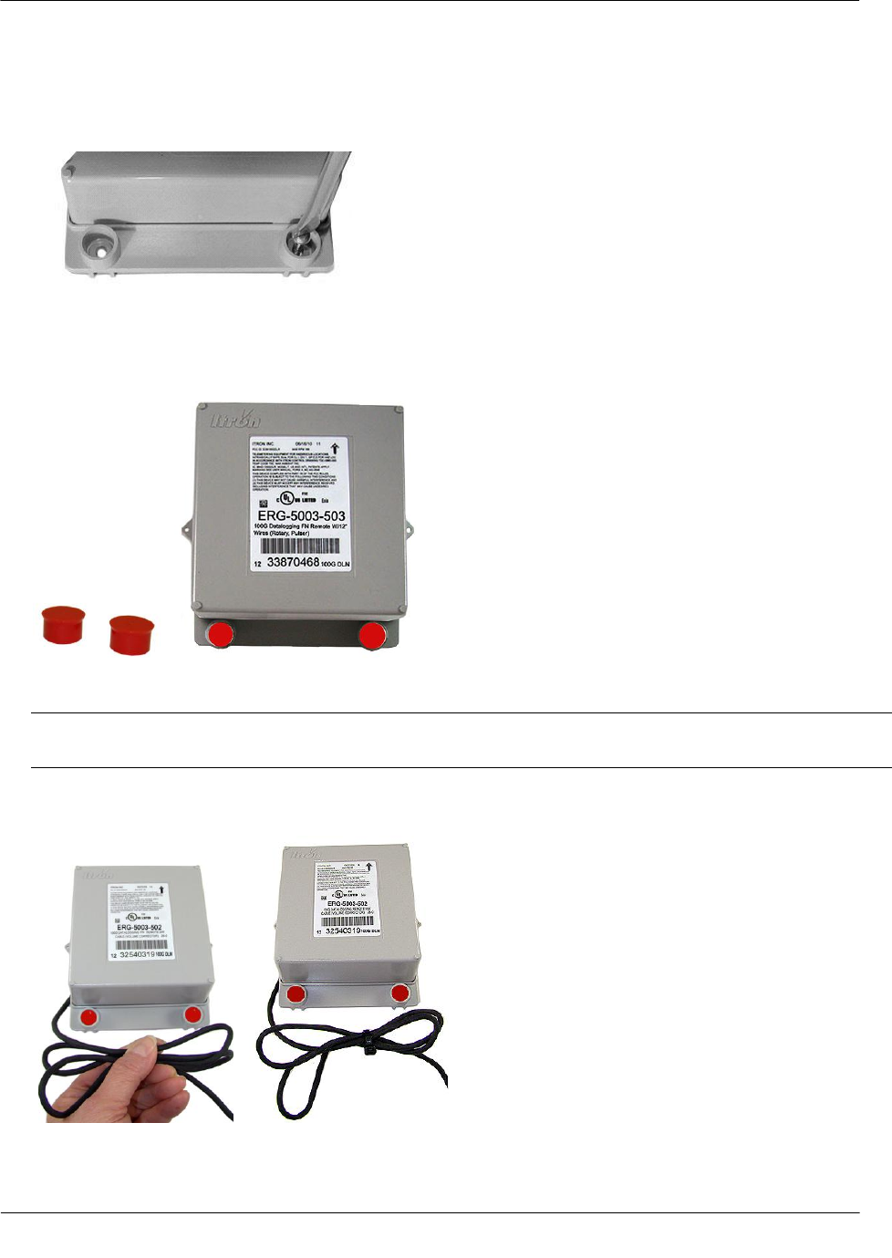
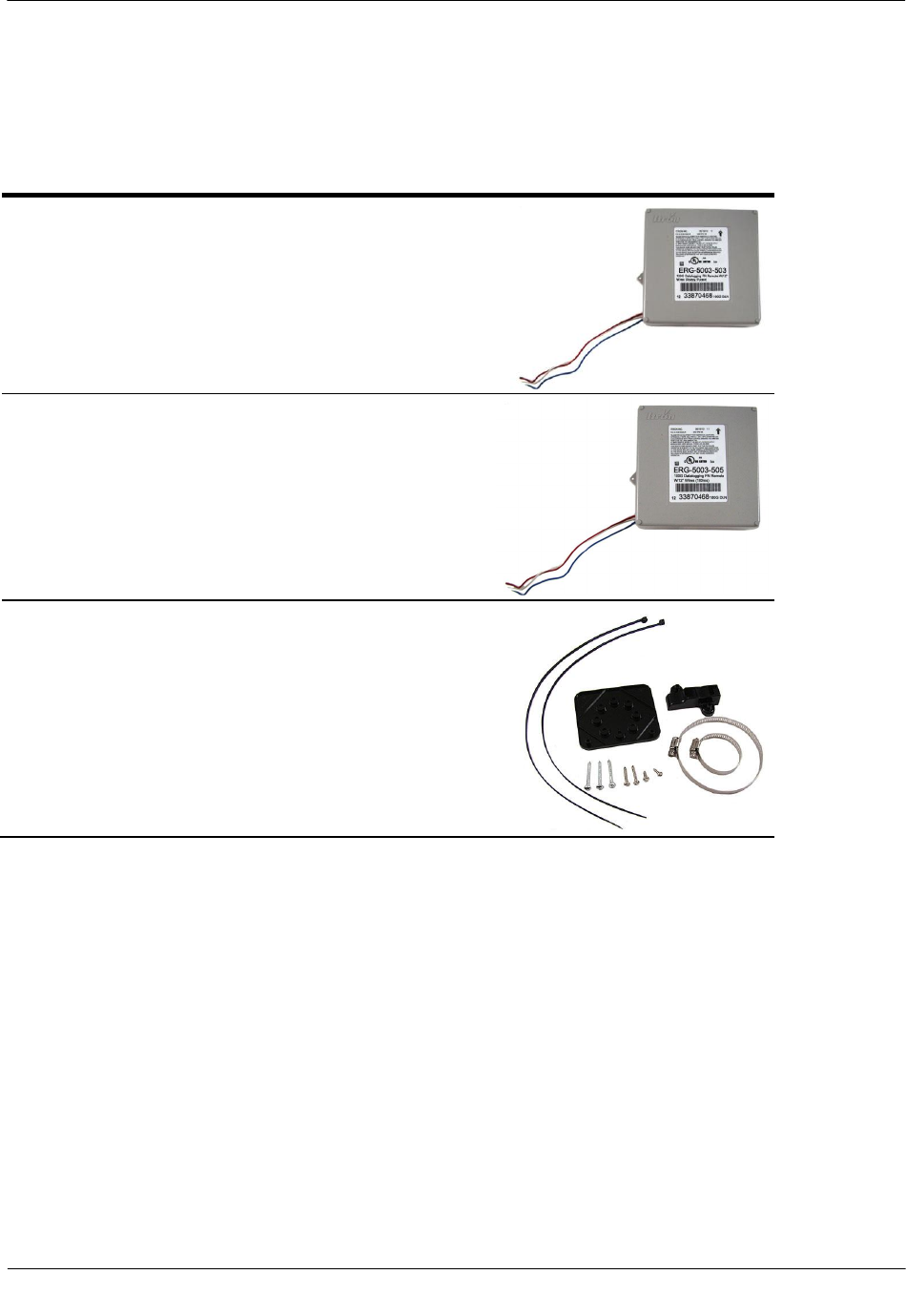
100G Remote Mount ERT Module part numbers: ERG-5000-501, ERG-5000-502, ERG-5000-503
100G Datalogging Remote Mount ERT Module: ERG-5002-501, ERG-5002-502, ERG-5002-503, ERG-5002-505
100G Datalogging FN Remote Mount ERT Module: ERG-5003-501, ERG-5003-502, ERG-5003-503, ERG-5003-505
Copyright
© 2009 - 2010 - 2011 Itron, Inc. All rights reserved.
Confidentiality Notice
The information contained herein is proprietary and confidential and is provided subject to the condition that (i) it is held in confidence except to the extent required otherwise by law and (ii) is
issued only for the purposes described herein. Any third party given access to this information is similarly bound in writing.
Trademark Notice
Itron is a registered trademark of Itron, Inc.
All other product names and logos in this documentation are used for identification purposes only and may be trademarks or registered trademarks of their respective companies.
Applicable Patents
U.S. Patent Numbers: 4,614,945; 4,753,169; 4,768,903; 4,799,059; 4,867,700
Canadian Patent Numbers: 1,254,949; 1,267,936; 1,282,118
Compliance Statement
This device complies with Part 15 of the FCC Rules. Operation of this device is subject to the following two conditions:
This device may not cause harmful interference.
This device must accept any interference that may cause undesirable operation.
This device must be permanently mounted such that it retains a distance of 20 centimeters (7.9 inches) from all persons in order to comply with FCC RF exposure levels.
Compliance Statement
This device complies with Industry Canada license-exempt RSS standard(s). Operation is subject to the following two conditions:
(1) this device may not cause interference, and
(2) this device must accept any interference, including interference that may cause undesired operation of the device.
Déclaration de conformité
Le présent appareil est conforme aux CNR d'Industrie Canada applicables aux appareils radio exempts de licence. L'exploitation est autorisée aux deux conditions suivantes :
(1) l'appareil ne doit pas produire de brouillage, et
(2) l'utilisateur de l'appareil doit accepter tout brouillage radioélectrique subi, même si le brouillage est susceptible d'en compromettre le fonctionnement.
Transportation Classification
The Federal Aviation Administration prohibits operating transmitters and receivers on all commercial aircraft. When powered, the 100G Datalogging FN remote ERT module is considered an
operating transmitter and receiver and cannot be shipped by air. All product returns must be shipped by ground transportation.
Modifications and Repairs
To ensure system performance, this device and antenna shall not be changed or modified without the expressed approval of Itron. Any unauthorized modification will void the user's authority to
operate the equipment.
Meter Installation/Removal
In the event of malfunction, all repairs should be performed by Itron. It is the responsibility of users requiring service to report the need for service to Itron.
Warning Follow these procedures to avoid injury to yourself or others:
The lithium battery may cause a fire or chemical burn if it is not disposed of properly.
Do not recharge, disassemble, heat above 100º Celsius (212º Fahrenheit), crush, expose to
water, or incinerate the lithium battery. Fire, explosion, and severe burn hazard.
Keep the lithium battery away from children.
Replace the lithium battery only with batteries meeting Itron specifications. Any other battery
may cause a fire or explosion.
Warning Only authorized Itron personnel should attempt repairs on Itron equipment. Attempts to do so
by others might void any maintenance contract with your company. Unauthorized service personnel might
also be subject to shock hazard on some Itron equipment if removal of protective covers is attempted.
Warning To prevent ignition of flammable or combustible atmospheres, disconnect power before
servicing.
Warning Substitution of components may impair intrinsic safety.
Suggestions
If you have comments or suggestions on how we may improve this documentation, send them to TechnicalCommunicationsManager@itron.com
If you have questions or comments about the software or hardware product, contact Itron Technical Support:
Contact
Internet: www.itron.com
E-mail: support@itron.com
Phone: 1 877 487 6602

TDC-0824-003 100G Datalogging FN ERT Module Installation Guide - Remote Mount iii
Proprietary and Confidential
Before You Begin .......................................................................................................... v
Document Purpose .............................................................................................................................. v
Chapter 1 100G Datalogging FN Remote ERT Module .............................................. 1
Transmission Modes ........................................................................................................................... 1
Specifications ...................................................................................................................................... 2
Related Documents .................................................................................................................. 2
100G Datalogging FN Remote ERT Module Meter Compatibility List ................................................ 3
Installation Prerequisites ..................................................................................................................... 5
Chapter 2 Mounting the 100G Datalogging FN Remote ERT Module ....................... 6
Installation Options .............................................................................................................................. 6
Mounting Screw Specifications ................................................................................................. 6
Mounting Installation Considerations .................................................................................................. 7
Mounting the Remote ERT Module on a Pipe .......................................................................... 8
Mounting the ERT Module on a Wall or Other Flat Vertical Surface ............................ 14
Chapter 3 Rotary Meter Installation .......................................................................... 16
Required Installation Materials Available from Itron .......................................................................... 17
Programming the Remote ERT Module for Dresser ROOTS® Rotary Meters .................................. 19
B3, LMMA & S3A CTR/TC Meter Drive Rates for Remote ERT Module Programming ................... 20
Installing the Remote ERT Module to the Elster American Meter RPM Series Rotary Meter .......... 21
Mounting the 100G Datalogging FN Remote Mount ERT Module .................................................... 27
Installing the Remote ERT Module to the Romet Electronically Compensated Meter (ECM2®) ...... 27
Connecting the Remote ERT Module to the Romet ECM2® Meter ................................................... 28
Romet ECM2® Mounting Requirement.............................................................................................. 28
Programming the 100G Datalogging FN Remote ERT Module ........................................................ 31
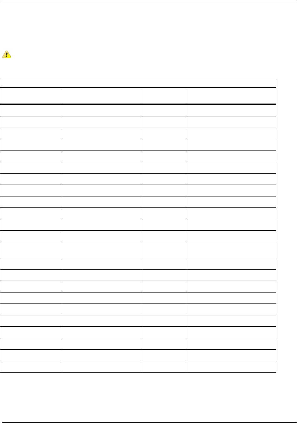
Chapter 4 Electronic Volume Corrector and Instrument Installation ..................... 33
Installation Prerequisites ................................................................................................................... 34
Installation Overview ......................................................................................................................... 34
Programming the Mercury Instrument ............................................................................................... 35
Code Settings.......................................................................................................................... 35
Wiring the ERT Module to the Instrument ......................................................................................... 36
Wiring Dual ERT Modules to a Mercury Instrument .......................................................................... 38
Wiring the Remote ERT Module to the Mercury TCI ........................................................................ 40
Connecting the 100G Datalogging FN Remote Mount ERT Module to the IMC/W2 or MC2 Cable . 43
Installing the ERT Module to the Dresser ROOTS® Micro Corrector (IMC/W2 or MC2) .................. 46
Programming the 100G Datalogging FN Remote ERT Module ........................................................ 50
Contents

Contents
TDC-0824-003 100G Datalogging FN ERT Module Installation Guide - Remote Mount iv
Proprietary and Confidential
Chapter 5 Diaphragm Meter Installation ................................................................... 52
Tools and Materials Supplied By You ............................................................................................... 52
Materials Available from Itron ............................................................................................................ 53
Replacement Gaskets ............................................................................................................. 53
Installing the 100G Datalogging FN Remote ERT Module ............................................................... 54
Installing 100G Datalogging FN Remote ERT Module Encoders ..................................................... 55
Index Cover Installation Required Materials ........................................................................... 60
Programming the 100G Datalogging FN Remote ERT Module ........................................................ 64
Chapter 6 DATTUS Meter Installation ....................................................................... 66
Installation Prerequisites ................................................................................................................... 66
Programming the DATTUS Meter ..................................................................................................... 66
Installation Overview ............................................................................................................... 66
Installing the Remote ERT Module to Itron DATTUS Meters ....................................... 67
Mounting the 100G Datalogging FN Remote ERT Module .......................................... 70
Programming the 100G Datalogging FN Remote ERT Module ................................... 71
Chapter 7 Sensus Sonix Meter Installation .............................................................. 73
Programming the Sensus Sonix Meter ............................................................................................. 73
Adjusting the Pulse Output for Sonix 600 and 880 Meters ..................................................... 73
Installing the 100G Datalogging FN Remote ERT Module with Sensus Sonix Meters ..................... 74
Sensus Sonix2000 Pulse Output Wiring ................................................................................. 74
Direct Mounting the Remote ERT Module to the Sonix Meter ................................................ 75
Connecting the Remote ERT Module to a Sensus Sonix 600 or 880 Meter .......................... 76
Programming the 100G Datalogging FN Remote ERT Module .............................................. 77
Index ............................................................................................................................. 79
Before You Begin
TDC-0824-003 100G Datalogging FN ERT Module Installation Guide - Remote Mount v
Proprietary and Confidential
The following documentation conventions are used:
Caution A Caution warns the user that failure to heed the information in the
note could result in loss of data. Be sure to carefully read a Caution note and
follow the advice/instructions.
Warning A Warning alerts you about potential physical harm to the user or
hardware. It is critical that you pay strict attention to Warning notes, read the
information carefully, and follow the advice/instructions.
Document Purpose
This installation guide provides step-by-step instructions for installing the 100G Series remote gas ERT
module on a wide variety of meters and instruments. This installation guide refers to the 100G series remote
ERT module as the 100G Datalogging FN remote ERT module. Mechanical and electrical installation
procedures are similar for all modules. 100G Datalogging FN remote ERT module compatible meters and
instruments are listed in the 100G Datalogging FN Remote ERT Module Meter Compatibility List on page 3.
Before You Begin
Tip A Note provides the user with extra hints to make a task easier to perform
or a concept easier to understand.
Note A Note supplies generic information to the user. The user could ignore
the information and continue a task without suffering any adverse
consequences.

TDC-0824-003 100G Datalogging FN ERT Module Installation Guide - Remote Mount 1
Proprietary and Confidential
Itron 100G series remote ERT modules are radio-frequency (RF) devices designed to transmit meter data to an
RF meter reading device within transmission distance of the remote ERT module. The 100G remote gas ERT
module was designed with a higher output power than earlier Itron remote gas ERT modules to achieve an
increased RF transmission distance. The 100G series remote gas ERT modules have greater output power to
meet Itron mobile and fixed network requirements. The first 100G remote gas ERT module offered high
transmit power capability which increased operational efficiency and reduced infrastructure costs. The 100G
Datalogging remote gas ERT module offers high transmit power with data logging capability (time-stamped
hourly interval data) for both mobile and fixed network applications. Itron's 100G Datalogging Fixed Network
(DLN) remote gas ERT module adds improved network performance through even higher transmit power,
accomplished using increased antenna efficiency and more robust optimized messaging structures.
The 100G Datalogging FN remote ERT module features tilt-tamper and cut cable-tamper reporting and
security seals to indicate physical tampering and minimize theft. Cut cable is reported when the cable is cut or
disconnected from the meter, instrument, or endpoint. 100G Datalogging FN remote ERT module circuitry
senses an electrical current break to report a cut cable tamper event.
Transmission Modes
The 100G Datalogging FN remote ERT module can be set to transmit in Fixed Network, Mobile and
Handheld, or Hard to Read Mobile and Handheld Mode.
Fixed Network Mode. The 100G Datalogging FN remote gas ERT transmits a high-powered network
interval message (NIM) RF message every five minutes. Output power in this mode is 500 milliwatts or
+27 dBm. Interspersed in the high power NIM, the 100G Datalogging FN remote ERT module transmits a
medium power RF message at 10 milliwatts or +10 dBm; expected battery life is 20 years.
Mobile High Power Mode. The 100G series remote gas ERT transmits a high-powered RF message
every 60 seconds. Output power in this mode is 250 milliwatts or +24dbm; expected battery life is 20
years.
Mobile and Handheld Mode. The 100G series remote gas ERT transmits a medium-powered RF
message every 15 seconds. Output power in this mode is 10 milliwatts or +10dBm; expected battery life is
20 years.
(Optional) Hard to Read Mobile and Handheld Mode. The 100G series remote FN gas module
transmits a high-powered RF message every 30 seconds. Output power in this mode is 250 milliwatts or
+24dBm; expected battery life decreases to 15 years in this mode. The Hard to Read Mobile and
Handheld Mode should only be used for exceptionally hard-to-read applications (such as meters installed
on roof tops or in sub-basements).
An FCC license is not required to read 100G series remote gas ERT modules.
CH A P T E R 1
100G Datalogging FN ERT Module

100G Datalogging FN ERT Module
TDC-0824-003 100G Datalogging FN ERT Module Installation Guide - Remote Mount 2
Proprietary and Confidential
Specifications
The functional and operational specifications for the 100G Datalogging FN remote ERT module are listed
below.
Functional Specifications
Description
Power source
Two "A" cell lithium batteries
Tamper detection
Tilt tamper and cut cable tamper
FCC compliance
Part 15 certified
Industry Canada compliance
RSS-210 certified
Intrinsically safe per
UL Class I, Division 1, Groups C and D
Product identification
Numeric and bar-coded ERT module type and serial number
Construction materials
Gray polycarbonate housing and back plate with encapsulated
electronics
Operational Specifications
Description
Operating temperatures
-40° to 158° F (-40° to +70° C)
Operating humidity
5 to 95 percent relative humidity
Program frequency
908 MHz
Transmit frequency
Spread spectrum 908 to 924 MHz ISM band
Data integrity
Verified in every data message
Related Documents
Document Title
Document Part Number
Gas Endpoint Meter Compatibility List
PUB-0117-002
Gas Endpoint Ordering Guide
PUB-0117-001
100G Datalogging Specification Sheet
Publication 100941SP-XX
Endpoint Link Programming Guide
TDC-0744*
Field Deployment Manager Endpoint Tools Mobile
Application Guide
TDC-0934*
Field Deployment Manager Field Representative's
Guide
TDC-0936*
*The last three digits of the user and installation guides represent the document's revision level. The revision
level is subject to change without notice.

100G Datalogging FN ERT Module
TDC-0824-003 100G Datalogging FN ERT Module Installation Guide - Remote Mount 3
Proprietary and Confidential
100G Datalogging FN Remote ERT Module Meter Compatibility
List
This table lists meters compatible with the 100G Datalogging FN remote ERT module. Due to continuous
research, product improvements, and enhancements Itron reserves the right to change this list without notice.
Meter
Model
Description
Class
Comments
ERT Module Type
ERT Module
Part Number
Elster/American/
Canadian
10 Metric (10B)
Iron case
Residential
2.5' cable with encoder
100G Remote
100G Datalogging Remote
100G Datalogging FN
Remote
ERG-5000-501
ERG-5002-501
ERG-5003-501
Sensus/Invensys
Sonix
12,16,25,57,
600,880,2000
Pulser
Metric
Cubic foot
Commercial
12" lead wires
100G Remote
100G Datalogging Remote
100G Datalogging FN
Remote
ERG-5000-503
ERG-5002-503
ERG-5003-503
National/ Lancaster
All meters
Where direct mount is
not compatible
Residential
2.5' cable with encoder
100G Remote
100G Datalogging Remote
100G Datalogging FN
Remote
ERG-5000-501
ERG-5002-501
ERG-5003-501
Itron/Actaris
Schlumberger/ Sprague
1A
Where direct mount is
not compatible
Residential
2.5' cable with encoder
100G Remote
100G Datalogging Remote
100G Datalogging FN
Remote
ERG-5000-501
ERG-5002-501
ERG-5003-501
Itron/Actaris/
Schlumberger/
Sprague
Metris 250
Straight Face meter
Residential
2.5' cable with encoder
100G Remote
100G Datalogging Remote
100G Datalogging FN
Remote
ERG-5000-501
ERG-5002-501
ERG-5003-501
Itron/Actaris/
Schlumberger/
Sprague
305
#2 flat-face meter
2.5' cable with encoder
100G Remote
100G Datalogging Remote
100G Datalogging FN
Remote
ERG-5000-501
ERG-5002-501
ERG-5003-501
Itron/Actaris/
Schlumberger/
Sprague
400
#3 flat-face meter
2.5' cable with encoder
100G Remote
100G Datalogging Remote
100G Datalogging FN
Remote
ERG-5000-501
ERG-5002-501
ERG-5003-501
Itron/Actaris/
Schlumberger/
Sprague
675, 1000
Front mount index
Commercial
2.5' cable with encoder
Also requires thicker gasket for
magnet hub to clear index box.
1-hole gasket: FAB-0014-001
2-hole gasket: FAB-0014-002
4-hole gasket: FAB-0014-003
100G Remote
100G Datalogging Remote
100G Datalogging FN
Remote
ERG-5000-501
ERG-5002-501
ERG-5003-501
Elster American
TC and STD CTR
American RPM series
rotary meters including
TC and non-TC.
Commercial
Meter must have a factory
installed pulser with connector
output. Purchase endpoint from
Itron and correct cable interface
from appropriate meter
manufacturer.
100G Remote (12' lead wires)
100G Datalogging Remote
(12" lead wires)
100G Datalogging FN
Remote (12" lead wires)
ERG-5000-503
ERG-5002-503
ERG-5003-503
Romet
STD CTR
600 through 56000
TC 2000 through 23000
RM series
Commercial
Meter must have a factory
installed pulser with connector
output. Purchase endpoint from
Itron and correct cable interface
from appropriate meter
manufacturer.
100G Remote (12' lead wires)
100G Datalogging Remote
(12" lead wires)
100G Datalogging FN
Remote (12" lead wires)
ERG-5000-503
ERG-5002-503
ERG-5003-503

100G Datalogging FN ERT Module
TDC-0824-003 100G Datalogging FN ERT Module Installation Guide - Remote Mount 4
Proprietary and Confidential
Meter
Model
Description
Class
Comments
ERT Module Type
ERT Module
Part Number
Romet
RM Series
ECM2
Electronically
compensated meter
Commercial
Meter must have connector pin
with factory-installed pulse
output. Purchase endpoint from
Itron and correct cable interface
from Romet. ECM2 must be
configured for 750ms "off-
time" between pulses. The
ECM2 must have firmware
version J or later.
100G Datalogging Remote
(12" lead wires)
100G Datalogging FN
Remote (12" lead wires)
ERG-5002-503
ERG-5003-503
Dresser ROOTS®
B3/LMMA
Dresser ROOTS®
rotary meters equipped
with WeigandWire
solid state pulsers
Commercial
Meter must have factory-
installed pulser with connector
output. Purchase endpoint from
Itron and correct cable interface
from Dresser. Dresser pulser
must be version 17 or higher to
be compatible.
100G Remote (12" lead
wires)
100G Datalogging Remote
(12" lead wires)
100G Datalogging FN
Remote (12" lead wires)
ERG-5000-503
ERG-5002-503
ERG-5003-503
Dresser ROOTS®
IMC/W2
MC2
Dresser ROOTS®
Micro Correctors
Commercial
Endpoint compatibile with
IMC/W2 firmware version
1.93 or earlier. Pulse width
must be set for 125ms. Pulse
output must be at 100CF(CM)
or higher.
100G Datalogging Remote
(12” lead wires)
100G Datalogging FN
Remote (12" lead wires)
ERG-5002-505
ERG-5003-505
Itron/Actaris
DATTUS fM2/fM3
Commercial
For all meter types, pulse width
must be set to .050 seconds.
Meter type 11M or smaller
must have pulse weight
minimum of 10 cubic feet or 1
cubic meter. Meter type 16M
or greater must have pulse
weight minimum of 100 cubic
feet or 1 cubic meter.
100G Datalogging Remote
(5' cable)
100G Datalogging FN
Remote (5' cable)
ERG-5002-502
ERG-5003-502
Mercury Instruments
EC-AT
Mini-P
Mini-AT
Mini-Max
Pressure and
temperature electronic
volume correctors
Commercial
Correctors must have a Form A
board; Form C is NOT
supported. Item #056 Pulse
Scaling Factor must be set to
2.0. Item #096 Cor Vol Display
must be set at 1, 2, 3, or 4
blanks. endpoint does NOT
support a setting of 0 blanks.
Item #115 Output Pulse Code
must be set at 1, 2, 3, or 4.
endpoint does NOT support an
Output Pulse Code of 0.
100G Remote (5'cable)
100G Datalogging Remote
(5' cable)
100G Datalogging FN
Remote (5' cable)
ERG-5000-502
ERG-5002-502
ERG-5003-502
Mercury Instruments
TCI
Temperature
Compensating Index
Commercial
Correctors must have a Form
A board, Form C is NOT
supported. Item #56 Pulse
Scaling Factor must be 2.0.
Item #96 must be 7, 6, 5, or 4
digits (1, 2, 3, & 4 blanks).
Endpoint does NOT support 8
digits (0 blanks). Item # 1014
set to the preset “Itron”
selection in the drop down
menu. Compatible firmware
versions on TCI are 1.06,
1.07, and 1.10.
100G Datalogging Remote
(5’ cable)
100G Datalogging Remote
(12” lead wires)
100G Datalogging FN
Remote (5’ cable)
100G Datalogging FN
Remote (12" lead wires)
5’: ERG-5002-502
12”:ERG-5002-503
ERG-5003-502
ERG-5003-503

100G Datalogging FN ERT Module
TDC-0824-003 100G Datalogging FN ERT Module Installation Guide - Remote Mount 5
Proprietary and Confidential
Installation Prerequisites
The following tools are required to install, program, and check the 100G Datalogging FN remote ERT
module. Some specific tools may be required dependent on meter or instrument type.
Medium flat-blade screwdriver
Small flat-blade screwdriver
Medium Phillips screwdriver
Hand pliers
Side-cutting pliers
1/4-inch nut driver or similar blunt tool
One-inch width putty knife
Adjustable wrench
3M Scotchlock E-9Y crimping tool, 3M Scotchlock E-9C cartridge tool, or similar crimping tool
All-weather electrical tape
Size T-10 Torx screwdriver
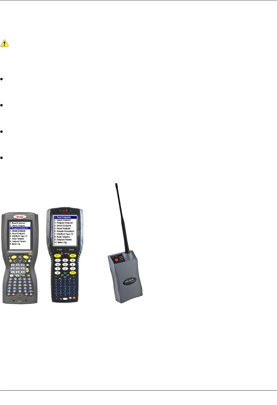
Itron programming device to program and check 100G Datalogging FN remote gas ERT module
installation and operation:
FC200SR handheld computer with Endpoint-Link or Endpoint-Link Pro software version 5.3 or higher or
Field Deployment Manager (FDM) software version 1.1 or higher
or
FC300 with SRead with Endpoint-Link or Endpoint Link Pro version 5.5 or higher or Field Deployment
Manager (FDM) software version 1.1 or higher
or
900 MHz Belt Clip Radio with Endpoint-Link version 5.5 or higher or Field Deployment Manager (FDM)
software version 1.1 or higher and a customer-supplied laptop
Note Reference the appropriate programming guide or specification sheet for correct software
version (see Related Documents on page 2).
TDC-0824-003 100G Datalogging FN ERT Module Installation Guide - Remote Mount 6
Proprietary and Confidential
This chapter provides the instructions to mount the 100G Datalogging FN remote ERT module on a pipe or
other flat vertical surface (wall).
Installation Options
Mount the 100G Datalogging FN remote ERT module using the Pipe Mount or Wall Mount (Flat Surface)
procedure.
Pipe Mount. Pipe mounting is used in conjunction with the Remote Mount Kit (Itron part number CFG-
0005-003). The pipe mount option places the ERT module on a pipe near the meter or instrument (not on a
wall surface). This option requires a meter manufacturer's cable to connect the ERT module to the meter
or instrument.
Flat Vertical (Wall) Mount. Installation using the wall mount option places the ERT module on a wall or
other vertical surface. A cable connects the ERT module to the meter or instrument.
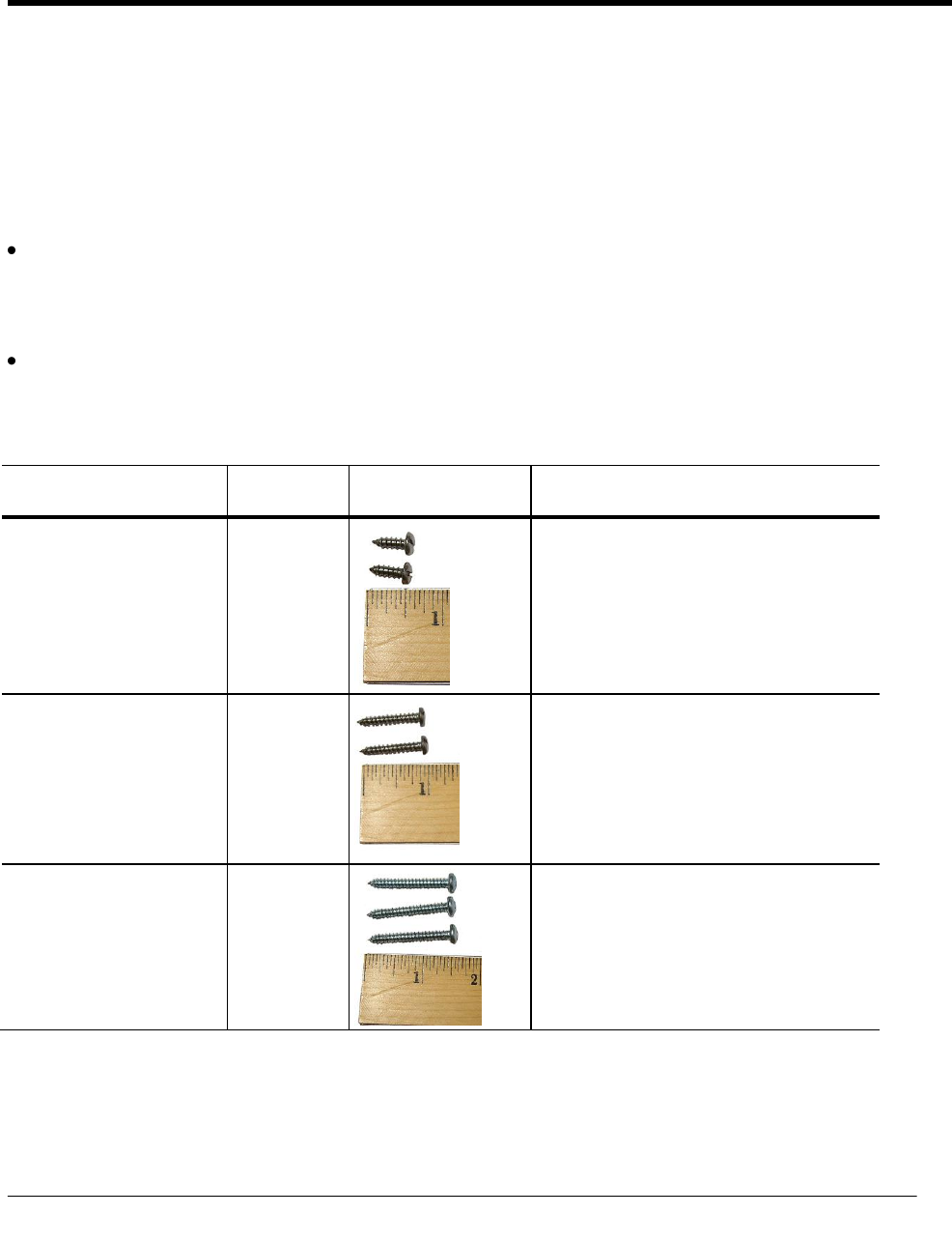
Mounting Screw Specifications
Application
Itron Part
Number
Description
To mount adapter plates on
pipe brackets
575-9930-016
8-16 x 1/2-inch length, Type 8 slotted pan-head
tapping screw - corrosion-resistant steel
To mount remote ERT
modules on adapter plates
575-9930-032
8-16 x 1-inch Type 8, slotted pan-head tapping
screw, corrosion-resistant steel
To mount remote ERT
modules on sheet metal
surfaces (to mount ERT
modules to wood surfaces, a
comparable wood screw is
required)
SCR-0009-001
10-16 x 1 1/2-inch Type AB thread for sheet
metal, Phillips pan-head tapping screw,
corrosion-resistant steel
CH A P T E R 2
Mounting the 100G Datalogging FN Remote ERT Module

Mounting the 100G Datalogging FN Remote ERT Module
TDC-0824-003 100G Datalogging FN ERT Module Installation Guide - Remote Mount 7
Proprietary and Confidential
Mounting Installation Considerations
Select a proper mounting location. Itron recommends mounting the 100G Datalogging FN remote ERT
module in close proximity to the meter or instrument. Some applications may require an extended cable-
length. The 100G Datalogging FN remote ERT module supports cable lengths up to 300 feet.
Mount the 100G Datalogging FN remote ERT module in a vertical position with the ERT module label
directional arrow pointed upward.
Caution Upright vertical positioning is very important because:
100G Datalogging FN remote gas modules are designed with the antenna in a
vertical direction so the antenna is parallel to the reading device (which has a
vertical antenna). Matching antenna polarity can greatly affect RF performance
and enable easy ERT module reading.
100G Datalogging FN remote gas modules are designed so the tilt tamper is
vertical. It is important to maintain vertical positioning in the field to enable tilt
tamper stability.
Warning Do not mount the 100G Datalogging FN remote ERT module in an orientation other
than vertical (remote ERT module label arrow pointed upward or downward). Violating the
mounting orientation requirements will void the product warranty.
Mounting the 100G Datalogging FN Remote ERT Module
TDC-0824-003 100G Datalogging FN ERT Module Installation Guide - Remote Mount 8
Proprietary and Confidential
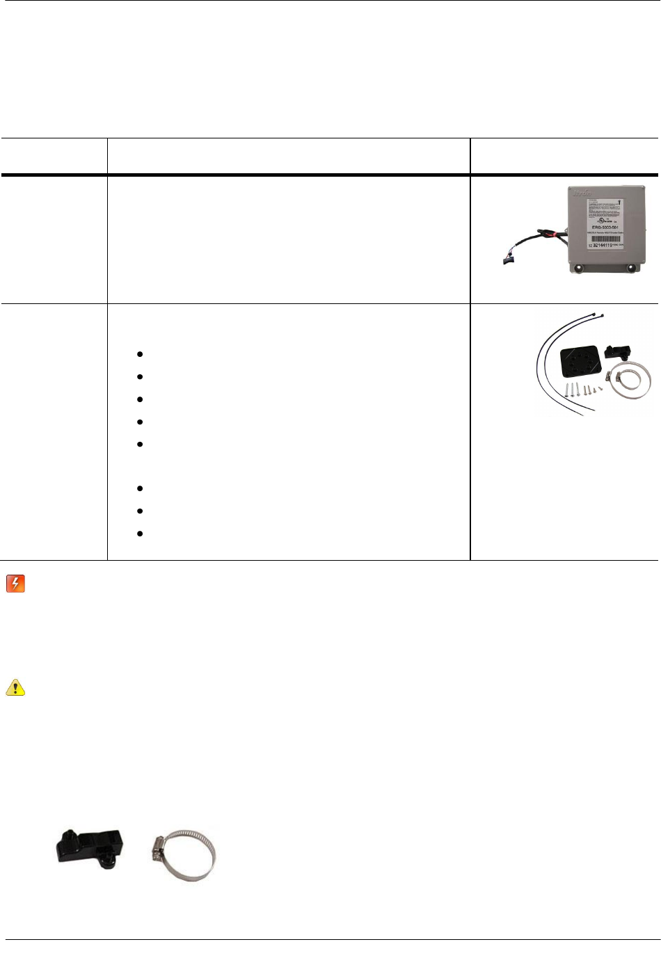
Mounting the Remote ERT Module on a Pipe
The following items are required to mount the 100G Datalogging FN remote ERT module on a pipe or
vertical flat surface (wall):
Itron Part
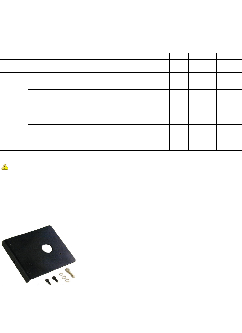
Number
Description
ERG-5003-501
ERG-5003-502
ERG-5003-503
ERG-5003-505
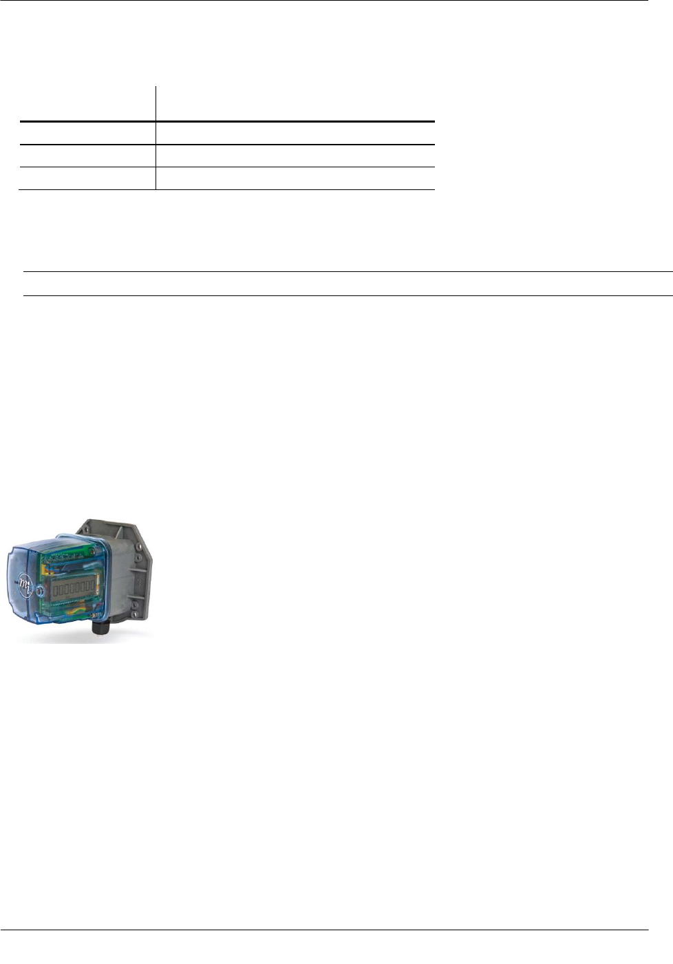
100G Datalogging FN Remote ERT Module
(ERG-5003-501 shown)
CFG-0005-003
Remote Mount Installation Kit
Kit includes:
2 band clamps
2 tamper seals
pipe bracket
cable ties
adapter plate
Screws:
(2) 1/2-inch - to attach the adapter plate to pipe bracket
(2) 1-inch - to attach the ERT module to the adapter plate
(3) 1 1/2-inch - to attach the ERT module to a vertical surface
(wall)
Warning Install the 100G Datalogging FN remote ERT module in an upright position. Any
position other than upright can negatively affect radio performance and potentially reduce
battery life.
To mount the pipe bracket on a vertical pipe
Caution Vertical mounting position is important to maximize RF performance. Mount the 100G
Datalogging FN remote ERT module with the module's label arrow pointing up. The module's
arrow must never point to either side or upside down. The module's tilt tamper functionality is
designed to operate with the module installed vertically.
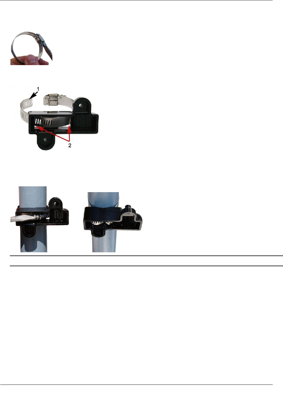
1. Remove the pipe bracket and band clamp from the Remote Mount Installation Kit (Itron part number
CFG-0005-003).
Mounting the 100G Datalogging FN Remote ERT Module
TDC-0824-003 100G Datalogging FN ERT Module Installation Guide - Remote Mount 9
Proprietary and Confidential
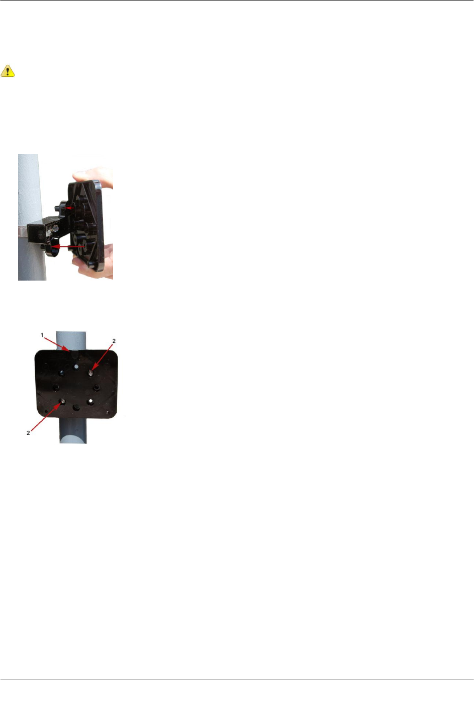
2. Loosen the band clamp screw until the end of the band releases.
3. Push the end of the clamp's band (1) through the holes (2) in the pipe bracket. The pipe bracket must be
oriented as shown below.
4. Place the band clamp around the pipe. The band will loosely wrap around the pipe. Push the end of the
band through the band clamp screw assembly. Turn the band clamp's screw assembly to fit into the pipe
bracket opening. Tighten the clamp screw until the band clamp is secure on the pipe.
Caution The pipe bracket must fit firmly against the pipe to prevent slippage.
Mounting the 100G Datalogging FN Remote ERT Module
TDC-0824-003 100G Datalogging FN ERT Module Installation Guide - Remote Mount 10
Proprietary and Confidential
To mount the adapter plate on the pipe bracket
Caution Vertical mounting position is important to maximize RF performance. Mount the 100G
Datalogging FN remote ERT module with the module's label arrow pointing up. The module's arrow
must never point to either side or upside down. The module's tilt tamper functionality is designed to
operate with the module installed vertically.
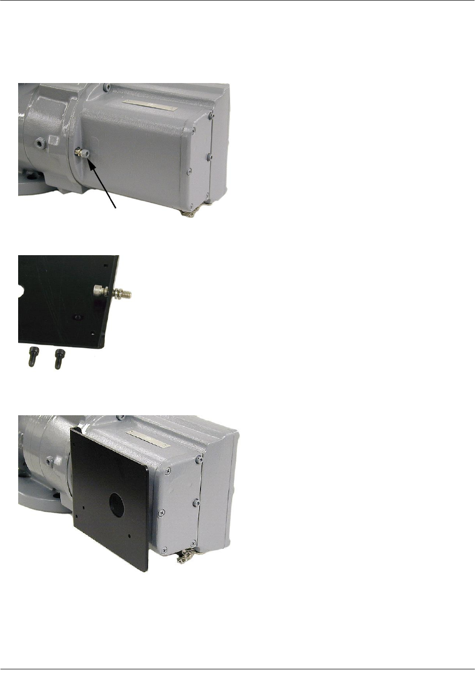
1. Place the adapter plate on the pipe bracket with the mounting lug at the top or bottom. The adapter plate
screw bosses fit into the pipe bracket recess.
2. Ensure the adapter plate is positioned as shown below with the mounting lug (1) at the top or bottom. To
install the adapter plate on a vertical pipe, use the two shortest (1/2-inch) adapter plate mounting screws
from the Remote Mount Installation Kit. Place the mounting screws (2) in the holes shown below.
Upright module mounting
3. Tighten both screws securely in an alternating fashion. Itron recommends 9 to 12-inch-pounds torque.
Mounting the 100G Datalogging FN Remote ERT Module
TDC-0824-003 100G Datalogging FN ERT Module Installation Guide - Remote Mount 11
Proprietary and Confidential
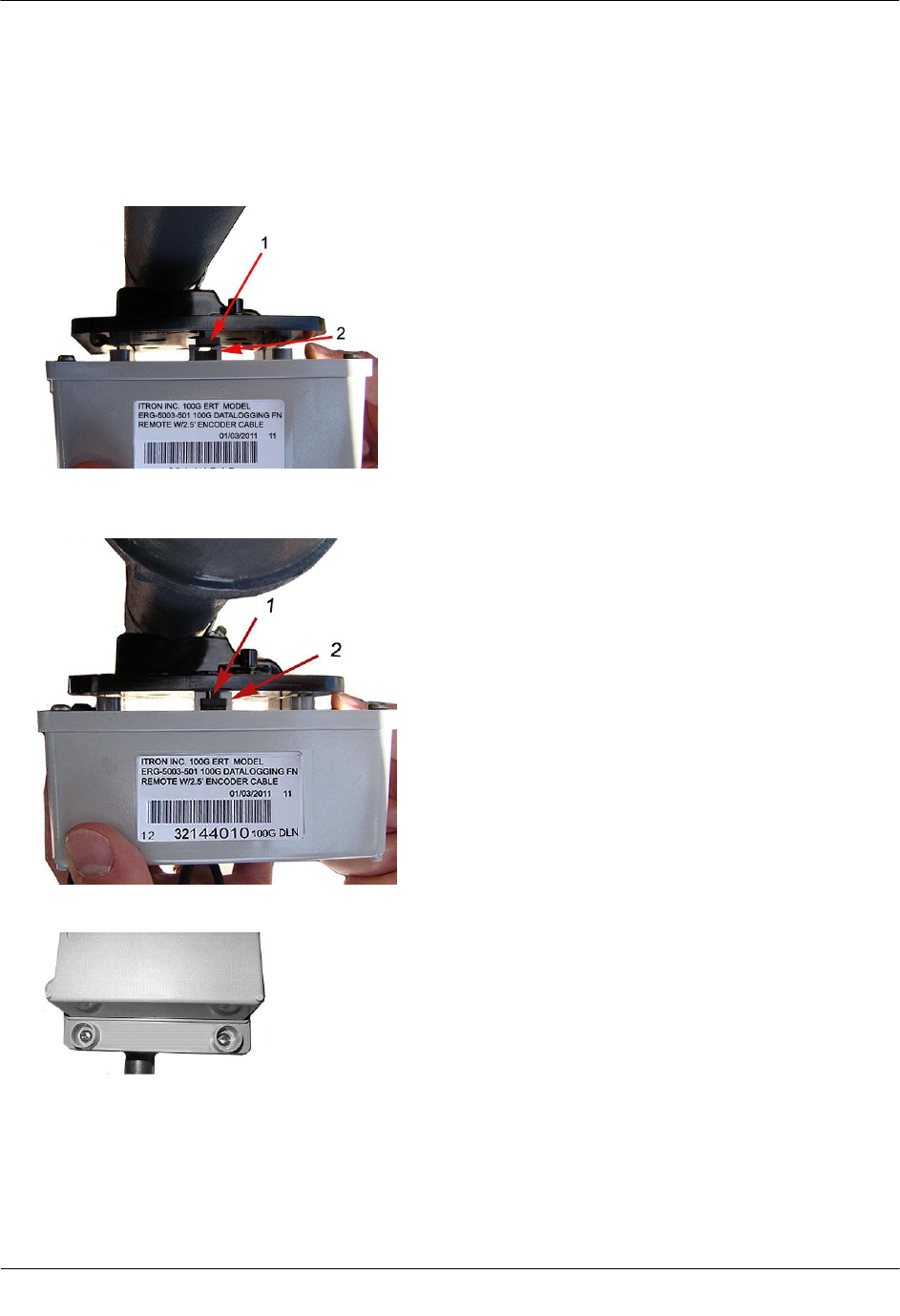
To mount the 100G Datalogging FN remote ERT module on the adapter plate
1. Take the 100G Datalogging FN remote ERT module and the two one-inch mounting screws from the
Remote Mount Installation kit. Place the back of the remote endpoint against the face of the adapter plate.
The adapter plate mounting lug (1) must be positioned just above the endpoint mounting lug recess (2).
2. Push up on the 100G Datalogging FN remote ERT module until the adapter plate mounting lug (1) is as
far as possible inside the module mounting lug recess (2).
3. Install the two one-inch ERT module mounting screws from the installation kit.
4. Tighten the module mounting screws evenly in an alternating fashion. Itron recommends 9 to 12 inch-
pounds of pressure.
Mounting the 100G Datalogging FN Remote ERT Module
TDC-0824-003 100G Datalogging FN ERT Module Installation Guide - Remote Mount 12
Proprietary and Confidential
Adapter Plate Mounting Positions
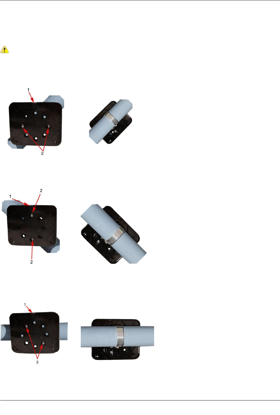
The following pictures show adapter plates mounted on horizontal or 45-degree angle pipes.
Caution Regardless of the pipe's direction, the adapter plate mounting lug must always be at
the top.
If the pipe is a 45 degree angle up to the right, install the adapter plate as shown below.
Typical module mounting Mounted adapter plate
If the pipe is a 45 degree angle up to the left, install the adapter plate as shown below.
Typical module mounting Mounted adapter plate
If the pipe is horizontal, install the adapter plate as shown below.
Typical module mounting Mounted adapter plate
Mounting the 100G Datalogging FN Remote ERT Module
TDC-0824-003 100G Datalogging FN ERT Module Installation Guide - Remote Mount 13
Proprietary and Confidential
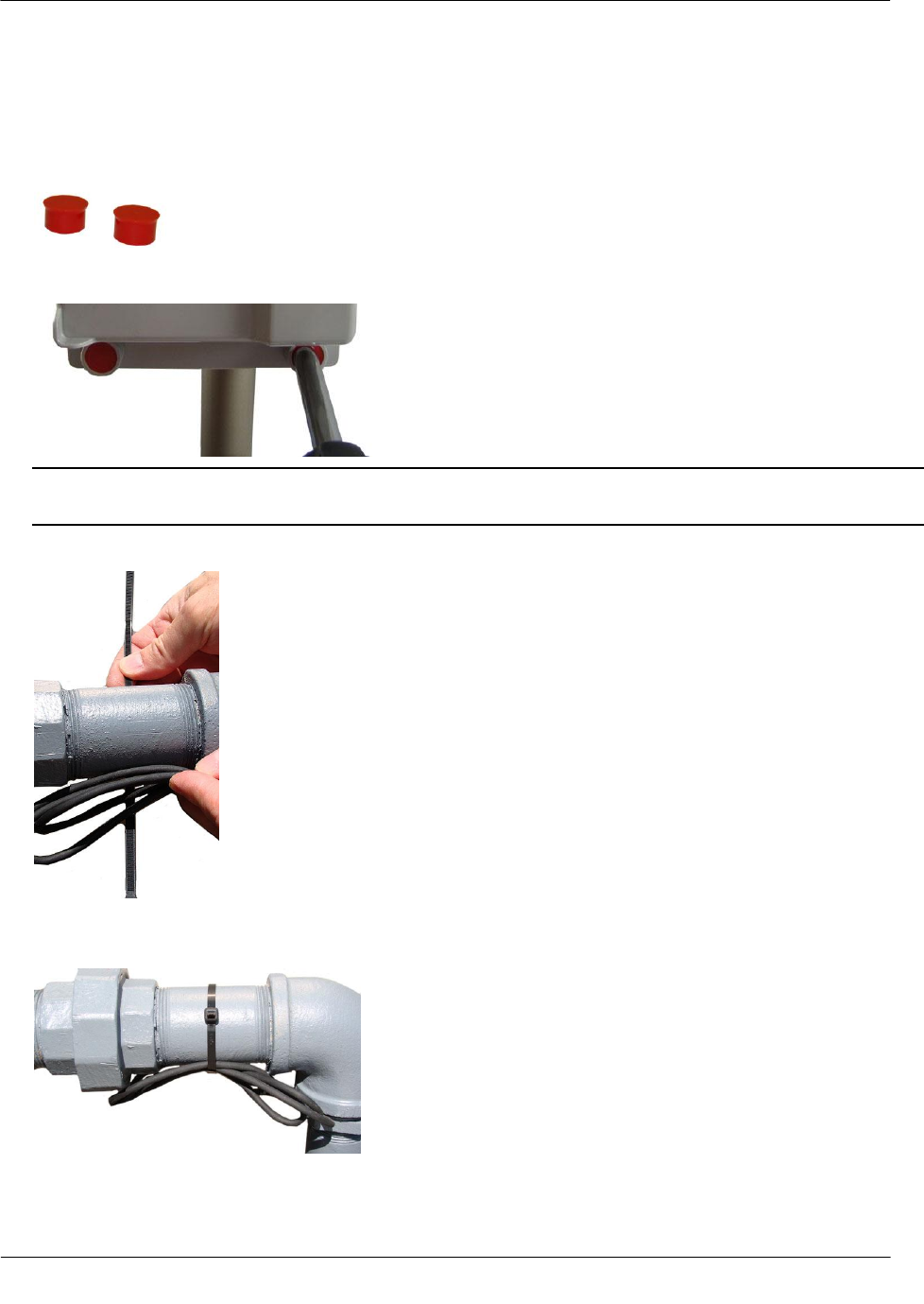
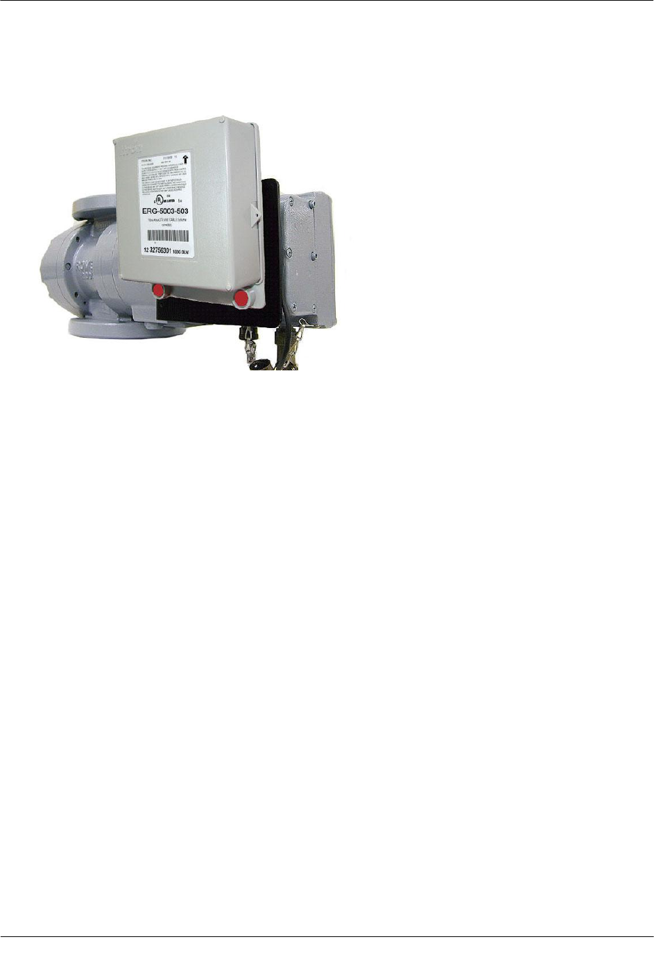
To install tamper seals and cable ties
1. Place the new tamper seals from the Remote Mount Installation Kit over the 100G Datalogging FN remote
ERT module mounting screws.
2. Firmly push both tamper seals all the way into place with a 1/4-inch nut driver or similar blunt tool.
Note A tamper seal is fully seated when the top of the tamper seal is approximately 1/16 inch below the
top of the screw recess.
3. Gather any excess ERT module cable. Loop a cable tie around the pipe and excess module cable.
4. Insert the chiseled end of the cable tie into the locking end and pull the cable tie tight. Cut off and properly
dispose the excess cable tie.
100G Datalogging FN remote ERT module pipe mount installation is complete.
Mounting the 100G Datalogging FN Remote ERT Module
TDC-0824-003 100G Datalogging FN ERT Module Installation Guide - Remote Mount 14
Proprietary and Confidential
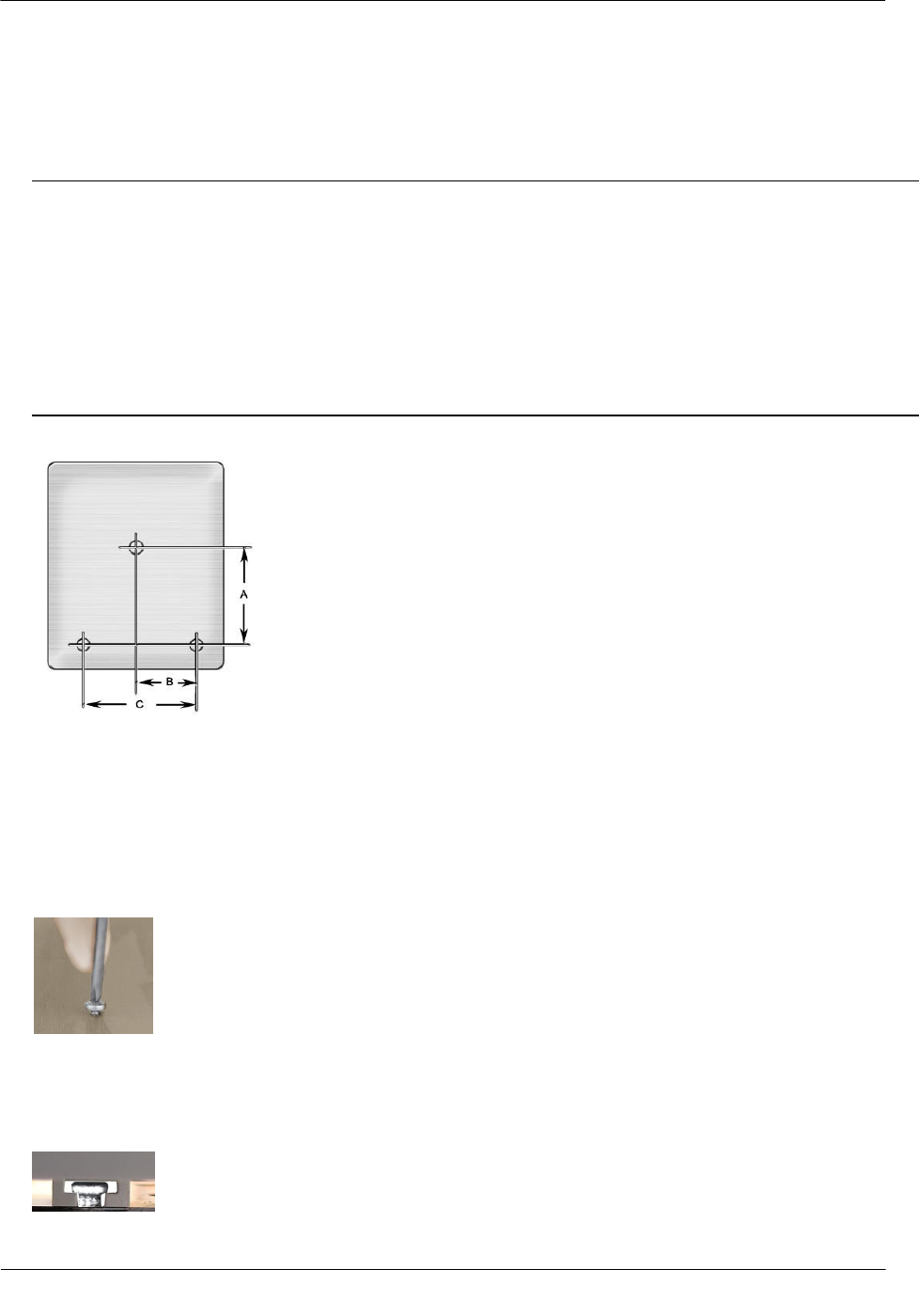
Mounting the ERT Module on a Wall or Other Flat Vertical Surface
To mount the 100G Datalogging FN remote ERT module on a wall or other flat vertical
surface
Note For easier installation, you may drill three pilot holes in the mounting surface (use the proper size
drill bit to accommodate the module mounting screws, see the Drilling Template below). When drilling
pilot holes to mount the 100G Datalogging FN remote ERT module, the holes for the two bottom screws
must be on a horizontal line. If you will mount the module on a sheet metal surface, use the mounting
screws included with the 100G Datalogging FN remote ERT module mounting kit. Use a comparable
wood screw to mount the module on a vertical wood surface.
Carefully select a mounting location free from electrical wires. The mounting location must have the
proper clearance to accommodate the 1-1/2-inch module mounting screws so nothing is damaged by the
drill or mounting screws.
100G Datalogging FN Remote ERT Module drilling template
A 3 inches
B 1-11/16 inches
C 3-3/8 inches
1. Using the three 1-1/2-inch mounting screws from the Remote Mount Installation Kit, turn the mounting
screw for the mounting lug (top of module) part way into the mounting surface.
2. Place the 100G Datalogging FN remote ERT module mounting lug recess (on the top of the module's
backplate) just under the screw head. Slide the module upward until the screw head fits completely inside
the mounting lug recess. Several adjustments may be necessary to properly position the screw for module
mounting.
Mounting the 100G Datalogging FN Remote ERT Module
TDC-0824-003 100G Datalogging FN ERT Module Installation Guide - Remote Mount 15
Proprietary and Confidential
3. Install the bottom two mounting screws. Fasten screws in an alternating fashion until fully tightened to
secure the module firmly in position.
To install tamper seals and cable ties
1. Place a new tamper seal (from the Remote Mount Installation Kit) over each endpoint mounting screw.
2. Firmly push both tamper seals into place with a 1/4-inch nut driver or similar blunt tool.
Note A tamper seal is fully seated when the top of the tamper seal is approximately 1/16-inch below the
top of the screw recess.
3. To reduce the risk of cable damage, secure the excess module cable with the cable ties from the Remote
Mount Installation Kit. Pull the cable tight. Remove and properly dispose the excess cable tie.
100G Datalogging FN remote ERT module installation on a vertical flat surface or wall is complete.
TDC-0824-003 100G Datalogging FN ERT Module Installation Guide - Remote Mount 16
Proprietary and Confidential
This chapter provides the instructions to install the Datalogging FN remote ERT module on rotary gas meters.
Reference the Gas Endpoint Meter Compatibility List (see 100G Datalogging FN Remote ERT Module Meter
Compatibility List on page 3) for rotary meters compatible with the 100G Datalogging FN remote ERT
module .
American rotary meter
Dresser ROOTS® Series LMMA rotary meter
Dresser ROOTS® series B3 meter
Romet Imperial series RM meter
Romet Imperial ECM2 meter
CH A P T E R 3
Rotary Meter Installation
Rotary Meter Installation
TDC-0824-003 100G Datalogging FN ERT Module Installation Guide - Remote Mount 17
Proprietary and Confidential
Required Installation Materials Available from Itron
The materials in the following table are required to install a 100G Datalogging FN remote ERT module.
Itron Part Number
ERG-5003-503
Note this remote ERT module comes standard
with 12-inch lead wires and may be shipped
directly to the meter manufacturer for a factory-
installed cable (interface). The interface cable
must be purchased directly from the meter
manufacturer.
ERG-5002-505
Note this remote ERT module comes standard
with 12-inch lead wires and may be shipped
directly to the meter manufacturer for a factory-
installed cable (interface). The interface cable
must be purchased directly from the meter
manufacturer.
CFG-0005-003
Remote Endpoint Mounting Kit
Rotary Meter Installation
TDC-0824-003 100G Datalogging FN ERT Module Installation Guide - Remote Mount 18
Proprietary and Confidential
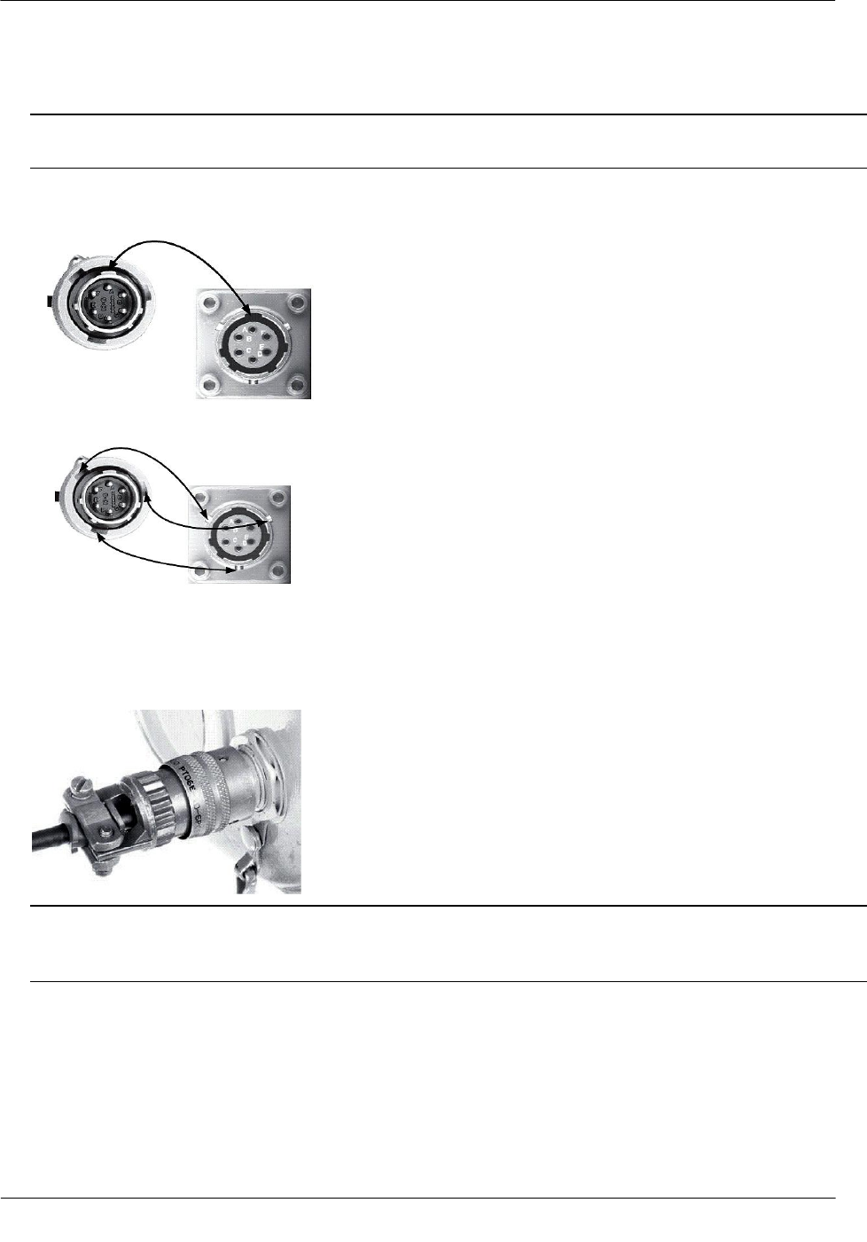
To connect the 100G Datalogging FN remote ERT module cable assembly to the rotary meter
Caution Verify the cable connector mates with the meter connector. Meter manufacturers use different
connector styles (types).
1. Align the large lug on the 100G Datalogging FN remote ERT module connector with the large notch on
the meter connector.
2. Align the lock ring notches on the module cable connector with the pins on the meter connector.
3. Hold the lock ring on the module connector back and push the plug into the meter connector until it is
securely seated.
4. Turn the lock ring clockwise as far as it will go. You will feel it snap into place when it locks.
Warning To remove the module connector plug from the meter connector jack, push in on the lock ring,
turn the lock ring counterclockwise as far as possible, and pull out the plug body. Do not pull on the
module's connector cable.
Rotary Meter Installation
TDC-0824-003 100G Datalogging FN ERT Module Installation Guide - Remote Mount 19
Proprietary and Confidential
5. Install the new Datalogging FN remote ERT module on the wall or a pipe using the Remote Endpoint
Mount Kit (Itron part number CFG-0005-003). See Mounting the 100G Datalogging FN Remote ERT
Module on page 6 for mounting instructions.
Programming the Remote ERT Module for Dresser ROOTS®
Rotary Meters
To program 100G Datalogging FN remote ERT modules for use with Dresser ROOTS® rotary meters, use the
meter drive rates from the drive rate table in this section.
Rotary Meter Installation
TDC-0824-003 100G Datalogging FN ERT Module Installation Guide - Remote Mount 20
Proprietary and Confidential
B3, LMMA & S3A CTR/TC Meter Drive Rates for Remote ERT Module
Programming
Caution Do not use these meter drive rates to program residential direct-drive or commercial
direct-drive modules. Use the information in the following tables to program 100G Datalogging
FN remote ERT modules connected to Dresser ROOTS® rotary meters..
B3, LMMA, S3A CTR/TC Meter Drive Rates
B3 CTR Meter Size
B3 CTR Meter Pulse Rate
LMMA CTR
Meter Size
LMMA CTR Meter Pulse Rate
8C
10
1.5M
10
11C
10
3M
10
15C
10
5M
10
2M
10
7M
10
3M
10
11M
10
5M
10
16M
100
7M
10
23M
100
11M
10
38M
100
16M
100
56M
100
23M
100
102M
100
38M
100
56M
100
LMMA CTR Meter
Size
LMMA CTR Meter Pulse
Rate
LMMA TC
Meter Size
LMMA TC Meter Pulse Rate
1.5M
10
1.5M
10
3M
10
3M
10
5M
10
5M
10
7M
10
7M
10
11M
10
11M
10
16M
100
16M
100
23M
100
38M
100
56M
100
102M
100
Rotary Meter Installation
TDC-0824-003 100G Datalogging FN ERT Module Installation Guide - Remote Mount 21
Proprietary and Confidential
Meters built 1/99 and beyond
Meters built prior to 1/99
B3 TC Meter Size
B3 TC Meter Pulse Rate
B3 TC Meter
Size
B3 TC Meter Pulse Rate
8C
10
8C
50
11C
10
11C
50
15C
10
15C
50
2M
10
2M
50
3M
10
3M
50
5M
10
5M
50
7M
10
7M
50
11M
10
11M
50
16M
100
16M
500
S3A CTR Meter Size
S3A CTR Meter Pulse Rate
S3A TC Meter
Size
S3A TC Meter Pulse Rate
1.5M
10
1.5M
10
3M
10
3M
10
5M
10
5M
10
7M
10
7M
10
11M
10
11M
10
16M
100
16M
100
Installing the Remote ERT Module to the Elster American Meter
RPM Series Rotary Meter
Some meter manufacturers provide ERT mounting kits and installation procedures for their meters. If the
100G Datalogging FN remote ERT module to Elster American RPM meter installation instructions are not
available, follow the installation procedure in this section.
Elster American Meter RPM Series Rotary Meter

Rotary Meter Installation
TDC-0824-003 100G Datalogging FN ERT Module Installation Guide - Remote Mount 22
Proprietary and Confidential
To install the 100G Datalogging FN remote ERT module on an Elster American RPM series
meter
1. Remove the meter's top plate by removing the two 5mm screws and carefully prying up on the plate. The
plate is secured with an o-ring seal. Remove the o-ring from the plate.
Caution If the o-ring is damaged during removal, obtain a replacement from Elster American Meter Co.
2. Look into the meter tower and find the meter switch lead and connector (4-pin).
3. If the lead and connector are not visible or cannot be found, remove the four 5mm mounting screws and
the register cover. The meter switch lead and connector will be visible inside the cover.
4. Feed the lead and connector into the register cover tower.
Note Save any meter tags. You will re-install them later in the installation process.
5. If you removed the register cover, replace the cover using the four (4) 5mm mounting screws.
Rotary Meter Installation
TDC-0824-003 100G Datalogging FN ERT Module Installation Guide - Remote Mount 23
Proprietary and Confidential
6. Attach the 4-pin male connector on the Elster American Meter adapter plate to the 4-pin female connector
inside the meter's tower. The connectors will slide together and latch.
7. Carefully push the connectors and wires into the meter tower housing.
8. Lubricate the o-ring with o-ring lubricant and install the o-ring on the adapter plate. Insert the adapter
plate into the tower and tighten the two 5 mm screws.

Rotary Meter Installation
TDC-0824-003 100G Datalogging FN ERT Module Installation Guide - Remote Mount 24
Proprietary and Confidential
To connect the manufacturer cable to the ERT module
Note Connection to an Elster American Meter requires a cable interface compatible to an Elster
American Meter RPM rotary meter.
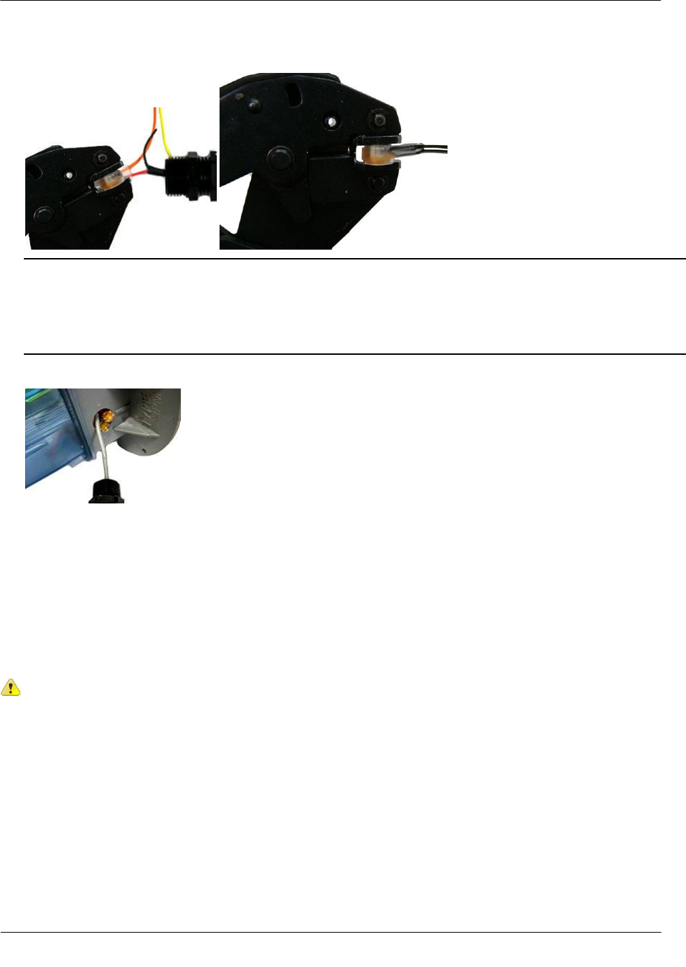
1. Trim the ERT module wires to 3.5-inches.
2. Carefully strip the insulation covering from the meter cable (purchased from the meter manufacturer)
approximately 1-1/2-inches from the end.
Caution Do not cut through the individual wire insulation.
3. Separate the black, white, and blue wires for connection to the Datalogging FN remote ERT module. Cut
off the unused wires even with the outer covering (insulation).
Caution Do not strip the individual wires.
Rotary Meter Installation
TDC-0824-003 100G Datalogging FN ERT Module Installation Guide - Remote Mount 25
Proprietary and Confidential
4. Connect the meter cable to the 100G Datalogging FN remote ERT module using 3M gel-cap connectors.
Follow the wire connection table and wiring diagrams below. See Installation Prerequisites on page 5 for
appropriate 3M crimping tools.
Important Use a crimping tool compatible with gel-connectors. Do not use a standard pliers for crimping
gel-connects. The crimping tool provides an even pressured crimp to make a secure connection. Apply
pressure for three seconds until the gel cap is fully crimped (collapsed) to allow time for the low viscosity
silicone-based gel to flow. If the silicone gel flows out of the crimped connector, avoid touching the gel.
Gel flowing from the connector provides environmental protection for the connection.
American RPM Meter to Datalogging FN remote ERT module Wire Connections
American RPM Meter wire
100G Datalogging FN remote mount ERT module wire
Red
Red
White
White
Black
Blue
Rotary Meter Installation
TDC-0824-003 100G Datalogging FN ERT Module Installation Guide - Remote Mount 26
Proprietary and Confidential
5. Insert the meter cable through the slot on the ERT module backplate. Install a cable tie to the meter cable
wire below the meter cable insulation to provide strain relief.
6. Tuck the connectors and cable tie into the ERT module housing. Place backplate on the assembly and
tighten the four backplate screws using a size T-10 Torx screwdriver.
Important Verify the cable tie and gel connectors are inside the module housing and the cable extends
out of the slot in the backplate. Torque the backplate mounting screws to 9-12 inch-pounds.
To install the Datalogging FN remote ERT module cable
1. Insert the plug on the cable connected to the ERT module into the receptacle on the meter adapter plate.
2. Tighten the threaded collar on the plug onto the American Meter interface receptacle. Verify the
connection is hand-tight.
Rotary Meter Installation
TDC-0824-003 100G Datalogging FN ERT Module Installation Guide - Remote Mount 27
Proprietary and Confidential
Mounting the 100G Datalogging FN Remote Mount ERT Module
Select an appropriate mounting location on adjacent piping close to the meter. Using the pipe bracket,
mounting plate and band clamps from the Remote Mount Kit (Itron part number CFG-0005-003), secure the
100G Datalogging FN remote ERT module. Use the cable ties from the kit to secure any excess wire to the
piping (see Mounting the 100G Datalogging FN Remote ERT Module on a Pipe on page 7).
Installing the Remote ERT Module to the Romet Electronically
Compensated Meter (ECM2®)
The Romet ECM2® meter has three Form A outputs that can be configured at the factory to provide any
combination of the following three outputs:
Uncorrected volume (UNC VOL)
Corrected volume (COR VOL)
Alarm
The pulse weight for the volumetric outputs is configured in SetUp Mode at Menu items > SET UNC OUT
and Menu items > SET COR OUT. Since Setup Mode is fully configurable, the ECM2® module is
universally adaptable to all Romet TC meter bodies. Reference the Romet technical manual for specific details
on the ECM2®.
Rotary Meter Installation
TDC-0824-003 100G Datalogging FN ERT Module Installation Guide - Remote Mount 28
Proprietary and Confidential
Connecting the ERT Module to the Romet ECM2® Meter
Connect the correct interface wirings and set the output pulse spacing to complete 100G Datalogging FN
remote ERT module installation with the Romet ECM2® meter. See the ECM2® Interface Wiring Table below
to complete wire connections.
Function
(+)UC
(-)UC
(+)CC
(-)CC
(+)ALM
(-)ALM
(+)Aux.CC
(-)Aux.CC
ERT Module wire
White and
Blue
Red
White and
Blue
Red
White and
Blue
Red
White and
Blue
Red
Pin location
for Cannon
Connector
Part
Number
34-125-20
C
B
A
B
E
D
34-125-40
A
B
C
D
E
F
34-125-41
A
B
C
D
E
F
34-125-42
E
F
A
B
C
D
34-125-43
A
B
E
F
C
D
34-125-44
A
B
34-125-45
A
B
E
D
C
F
34-125-50
3
1
2
5
6
4
34-125-51
3
1
2
5
6
4
Caution Set the ECM2® output pulse spacing to 750ms for operation with the 100G Datalogging
FN remote ERT module. Output spacing represents an off-time between pulses.
Romet ECM2 Mounting Requirement
This mounting procedure requires the Romet ECM2/ERT Mounting Kit (Romet part number 34-444-1-KIT).
Rotary Meter Installation
TDC-0824-003 100G Datalogging FN ERT Module Installation Guide - Remote Mount 29
Proprietary and Confidential
To mount the 100G Datalogging FN remote ERT module on the Romet ECM2 meter
1. Remove the module screw from the back of the ECM2 meter and discard.
2. Insert the mounting screw fitted with the three lock washers. Two lock washers are used as spacers as
shown.
3. Attach the mounting plate to the meter. Insert the mounting screw where the module screw was removed.
Torque the mounting screw to 5-7 ft.lbs. to secure the plate to the Romet meter.
4. Mount the 100G Datalogging FN remote ERT module using the pre-drilled holes on the mounting plate
and the module mounting screws.
5. Place new tamper seals over the two screws. Press tamper seals into place using an 11/32-inch nut driver
or similar blunt tool.
Rotary Meter Installation
TDC-0824-003 100G Datalogging FN ERT Module Installation Guide - Remote Mount 30
Proprietary and Confidential
6. Connect the module to the meter using the previously installed cable interface.
Rotary Meter Installation
TDC-0824-003 100G Datalogging FN ERT Module Installation Guide - Remote Mount 31
Proprietary and Confidential
Programming the 100G Datalogging FN Remote ERT Module
Caution You must program the 100G Datalogging FN remote ERT module before use.
Follow the steps in this section to properly program the ERT module.
Program the 100G Datalogging FN remote ERT modules using:
A FC200SR handheld computer with Endpoint-Link® or Endpoint-Link Pro version 5.3 or higher or Field
Deployment Manager (FDM) software version 1.1 or higher
or
A FC300 with SRead handheld computer with Endpoint-Link or Endpoint-Link Pro version 5.5 or higher
or Field Deployment Manager (FDM) software version 1.1 or higher
or
A 900MHz Belt Clip Radio with Endpoint-Link version 5.5 or higher or Field Deployment Manager
(FDM) software version 1.1 or higher and a customer-supplied laptop. The Belt Clip Radio connects to the
user-supplied laptop using a USB cable or Bluetooth.
See the Endpoint-Link v5.3 (or higher) Endpoint Programming Guide (TDC-0744) or the Field
Deployment Manager Endpoint Tools Mobile Application Guide (TDC-0934) for more complete
programming information.
FC200SR FC300 with SRead 900MHz Belt Clip Radio

Rotary Meter Installation
TDC-0824-003 100G Datalogging FN ERT Module Installation Guide - Remote Mount 32
Proprietary and Confidential
To program the 100G Datalogging FN remote ERT module
1. Program the meter drive rate into the 100G Datalogging FN remote ERT module using a handheld
computer or Belt Clip Radio and laptop computer. For all programming and Check Endpoint operations
using a handheld computer, hold the handheld as close to vertical as possible. For best success, keep the
handheld within six feet of the target ERT module. Verify you have the correct programming mode (Fixed
Network Mode, Mobile High Power Mode, Mobile/Handheld Mode, or Hard to Read Mobile/Handheld
Mode) for your application. Programming parameters are based on the configuration file loaded into the
programming device. During programming, the 100G Datalogging FN remote ERT module is set to the
nearest 100 cubic feet; the last two digits (tens and units) are programmed as zeros (0). After
programming is complete, the ERT module assembly will read to the nearest cubic foot.
2. Read or Check the 100G Datalogging FN remote ERT module using the handheld computer or Belt Clip
Radio.
If the read result is higher than the number programmed in step 1, the 100G Datalogging FN remote
ERT module is counting correctly.
If the read result is not higher than the number programmed in step 1, replace the 100G Datalogging
FN remote ERT module.
TDC-0824-003 100G Datalogging FN ERT Module Installation Guide - Remote Mount 33
Proprietary and Confidential
This section provides the instructions to install the 100G Datalogging FN remote ERT module on:
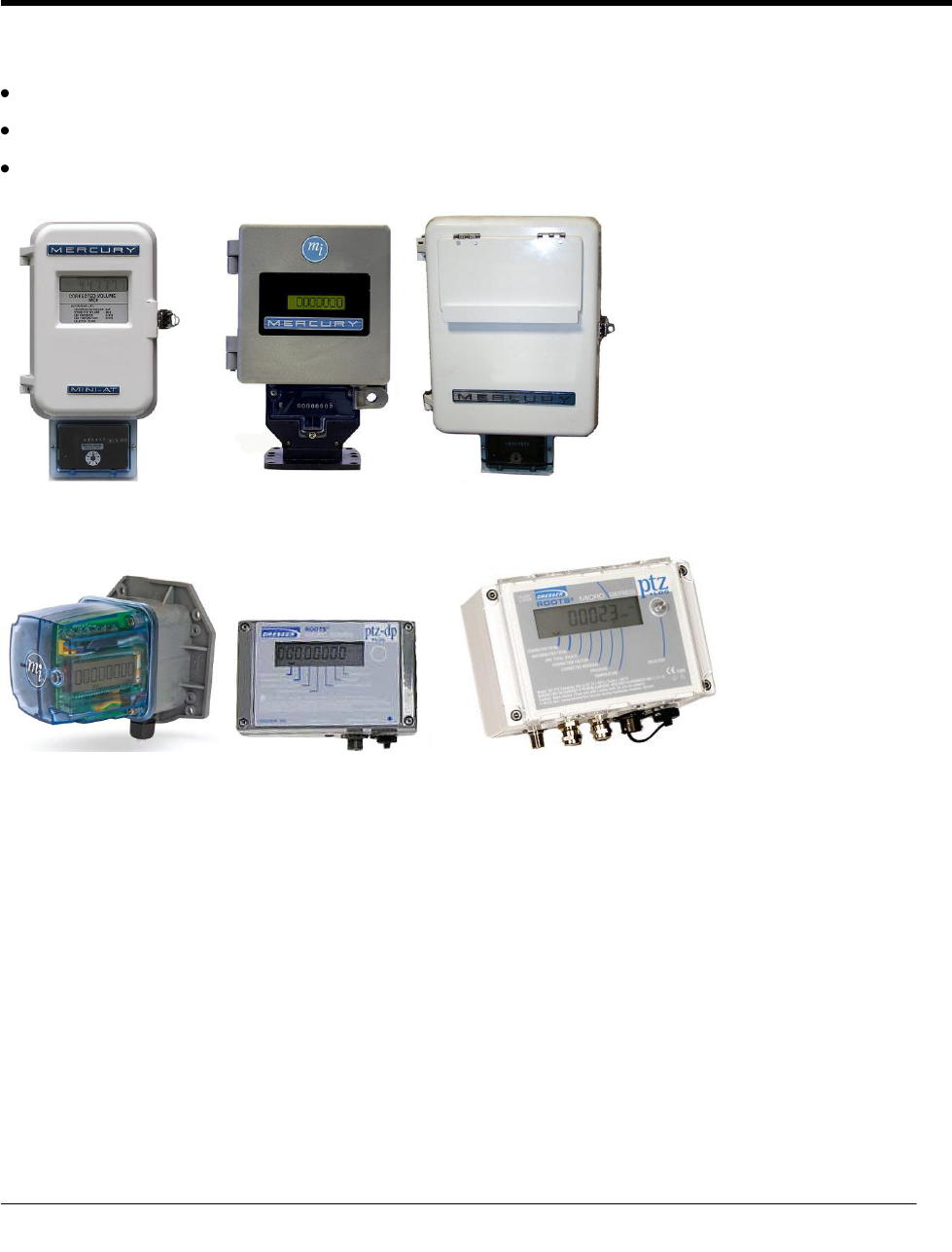
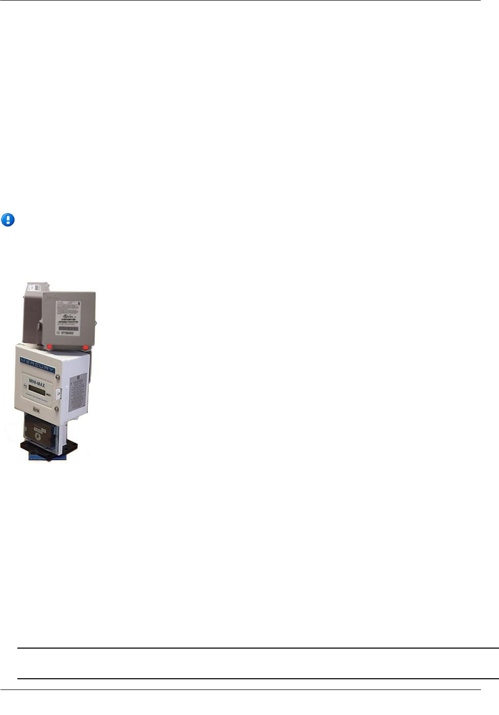
Mercury Instruments Mini-P, Mini-AT, Mini-Max, and EC-AT
Mercury Instruments Temperature Compensated Indexes (TCI)
Dresser ROOTS IMC/W2 and MC2 Micro Correctors
Mini-AT Mini-Max EC-AT
TCI IMC/W2 MC2
CH A P T E R 4
Electronic Volume Corrector and Instrument Installation

Electronic Volume Corrector and Instrument Installation
TDC-0824-003 100G Datalogging FN ERT Module Installation Guide - Remote Mount 34
Proprietary and Confidential
Installation Prerequisites
100G Datalogging FN remote ERT module installation to a volume corrector or instrument requires:
100G Datalogging FN remote ERT module compatible to a volume corrector or instrument (see the 100G
Datalogging FN Remote ERT Module Meter Compatibility List on page 3).
Volume corrector or instrument compatible with the remote ERT module.
Proper tools and devices for installation and programming (see Installation Prerequisites on page 5).
Installation Overview
Installing the 100G Datalogging FN remote ERT module to a volume corrector or instrument involves five
tasks:
1. Programming the Mercury Instrument (see Programming the Mercury Instrument on page 34 or reference
the Mercury Instrument Programming Guide for more information).
2. Installing Mercury retrofit parts (if necessary).
3. Attaching the Datalogging FN remote ERT module to a pipe or vertical flat surface (wall) (see Mounting
the 100G Datalogging FN Remote ERT Module).
4. Connecting the Datalogging FN remote ERT module on page 6 to the Mercury Instrument Volume
Corrector (see To wire the ERT Module to the Mercury Instrument on page 37), Mercury Instrument
Temperature Compensating Index (TCI), or Dresser ROOTS Micro Corrector (IMC/W2 or MC2).
5. Programming the Datalogging FN remote ERT module (see Programming the 100G Datalogging FN
Remote ERT Module on page 30).
Electronic Volume Corrector and Instrument Installation
TDC-0824-003 100G Datalogging FN ERT Module Installation Guide - Remote Mount 35
Proprietary and Confidential
Programming the Mercury Instrument
Code Settings
Volume
Instrument
Type
Item Code Settings and Corresponding Terminal Board Channel
Terminal Board Connections*
Pulse Output
Options
Channel A
Channel B
Channel C
Number of
Blanked digits
on CorVol
Display
Pulse Output Spacing
Ka, Ya = Channel A
#056
#93
#057
#094
#058
#095
#96
#115
#1014
#1015
ECAT
Pulse Board Ver-1(3)
Form-C
n/a
n/a
n/a
n/a
n/a
n/a
n/a
n/a
n/a
n/a
Module does not support a Form-C pulse output
board.
Pulse Board Ver-2(3)
Form-A
2.0000
0
2.0000
0
2.0000
0
1, 2, 3, or 4
1, 2, 3, or 4
n/a
n/a
Ka, Kb, Kc (Red Wire)
Ya, Yb, Yc (Blue & White Wire)
Connection must be on same terminal board
channel (for example, Ka/Ya; Kb/Yb; Kc/Yc).
Pulse Board Ver-3(2)
Form-C1 Form-A
n/a
n/a
n/a
n/a
2.0000
0
1, 2, 3, or 4
1, 2, 3, or 4
n/a
n/a
Kc (Red Wire) Y (Blue & White Wire). For this
option, module must be connected to Channel C.
Mini with
Form A
Mainboard
Main Board Type-2
2.0000
0
n/a
n/a
n/a
n/a
1, 2, 3, or 4
1, 2, 3, or 4
n/a
n/a
K (Red Wire) Y (Blue & White Wire).
For optional SPA Bd., jumper must be installed
on J1-B as indicated in the Mercury Quick
Reference Guide (page 148) for Form A.
Mini-AT
JB29, JB30 & JB31
Jumpered for Form-
A
2.0000
0
2.0000
0
n/a
n/a
1, 2, 3, or 4
1, 2, 3, or 4
n/a
n/a
K (Red Wire) Y (Blue & White Wire).
For optional SPA Bd., jumper must be installed
on J1-B as indicated in the Mercury Quick
Reference Guide (page 148) for Form-A.
JB29, JB30 & JB31
Jumpered for Form-
C
n/a
n/a
n/a
n/a
n/a
n/a
n/a
n/a
n/a
n/a
Module does not support a Form-C pulse output
board.
Mini-Max
All Main Boards
2
0
2
0
n/a
n/a
1, 2, 3, or 4
1, 2, or 4
n/a
n/a
K (Red Wire) Ya or Yb (Blue & White Wire)
TCI
Form C Main Board
n/a
n/a
n/a
n/a
n/a
n/a
n/a
n/a
n/a
n/a
Module does not support a Form-C pulse output
board.
Form A Main Board
2.0000
0
2.0000
0
n/a
n/a
1, 2, 3, or 4 blanks
(7, 6, 5, or 4 active)
n/a
Itron selection
in dropdown
menu.
Itron selection
in dropdown
menu
Connections to channels of output pulses are
made through loose unterminated cable wires
and gel connect connectors.
Notes:
Code 0 for items 093, 094 & 095 = Corrected Volume Pulse Data
Code 1 for item 115 = 1.000 Sec.
Code 2 for item 115 = 2.000 Sec.
Code 1 for item 096 = blank 1 digit and display 7 digits
Code 2 for item 096 = blank 2 digits and display 6 digits
Code 3 for item 096 = blank 3 digits and display 5 digits
Code 4 for item 096 = blank 4 digits and display 4 digits
*For more information, see pages 11-20 of the "Basic Pulse Information for Mercury Instruments, Inc., Electronic Volume Correctors" manual, or contact Mercury Instruments at
513-272-1111.
Electronic Volume Corrector and Instrument Installation
TDC-0824-003 100G Datalogging FN ERT Module Installation Guide - Remote Mount 36
Proprietary and Confidential
Mercury Instrument programming parameters:
Caution A Mercury Instrument must have a Form A board. A Form C board is not compatible
with the 100G Datalogging FN remote ERT module.
For TCI, when using both outputs, items 1014 and 1015 must be set to Itron.
Item #056: Pulse A Scaling. Set at 2.0000 for a form A switch.
Item #057: Pulse A Scaling. Set at 2.0000 for a form A switch.
Item #058: Pulse A Scaling. Set at 2.0000 for a form A switch.
Item #090: Corrected Volume Units: Code (0-20) selects the unit of measure for Corrected Volume
(Item000) and other "CorrVol" related items.
Item #092: Uncorrected Volume Units: Code (0-20) selects the unit of measure for Uncorrected Volume
(Item002) and other "UncVol" related items.
Item # 093, 094, 095: Type of gas volume information to be sent. For "CorrVol" selected, must be set at 0.
Item # 096: Corrected Volume Display: Must be set at 1, 2, 3 or 4 blanks. Module does not support a
setting of 0 blanks.
Item # 097: Uncorrected Volume Display: Must be set at 1, 2, 3, or 4 blanks. Module does not support a
setting of blanks.
Item # 098: Check drive rate of the corrector. Should be the same as the plate above the uncorrected dials
and the same as the plate on the index drive of the meter.
Item # 115: Output Pulse Code: Must be set at 1 or 2.
Wiring the ERT Module to the Instrument
Use the terminal strip connector (Phoenix connector) in the Mercury Instrument to connect the 100G
Datalogging FN remote ERT module to the instrument.
Note In Mercury Instrument EC-AT correctors, the connector may be soldered to the pulse board.
The 100G Datalogging FN remote ERT module has three lead wires (red, white, and blue). The red wire is
attached according to Mercury Instrument Code Settings (see Code Settings on page 35).
Electronic Volume Corrector and Instrument Installation
TDC-0824-003 100G Datalogging FN ERT Module Installation Guide - Remote Mount 37
Proprietary and Confidential
The blue and white wires are twisted together and attached according to Mercury Instrument's Code Settings
(see Code Settings on page 35).
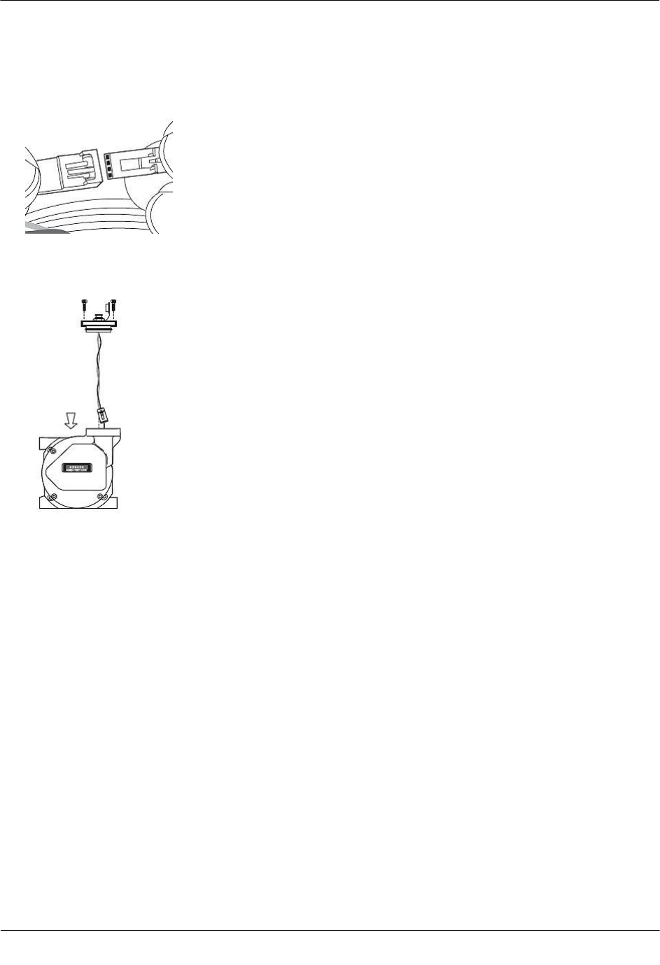
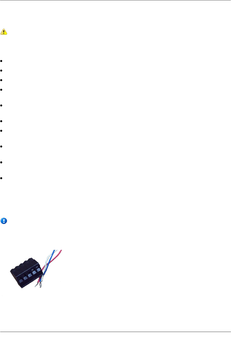
To wire the ERT module to the Mercury Instrument
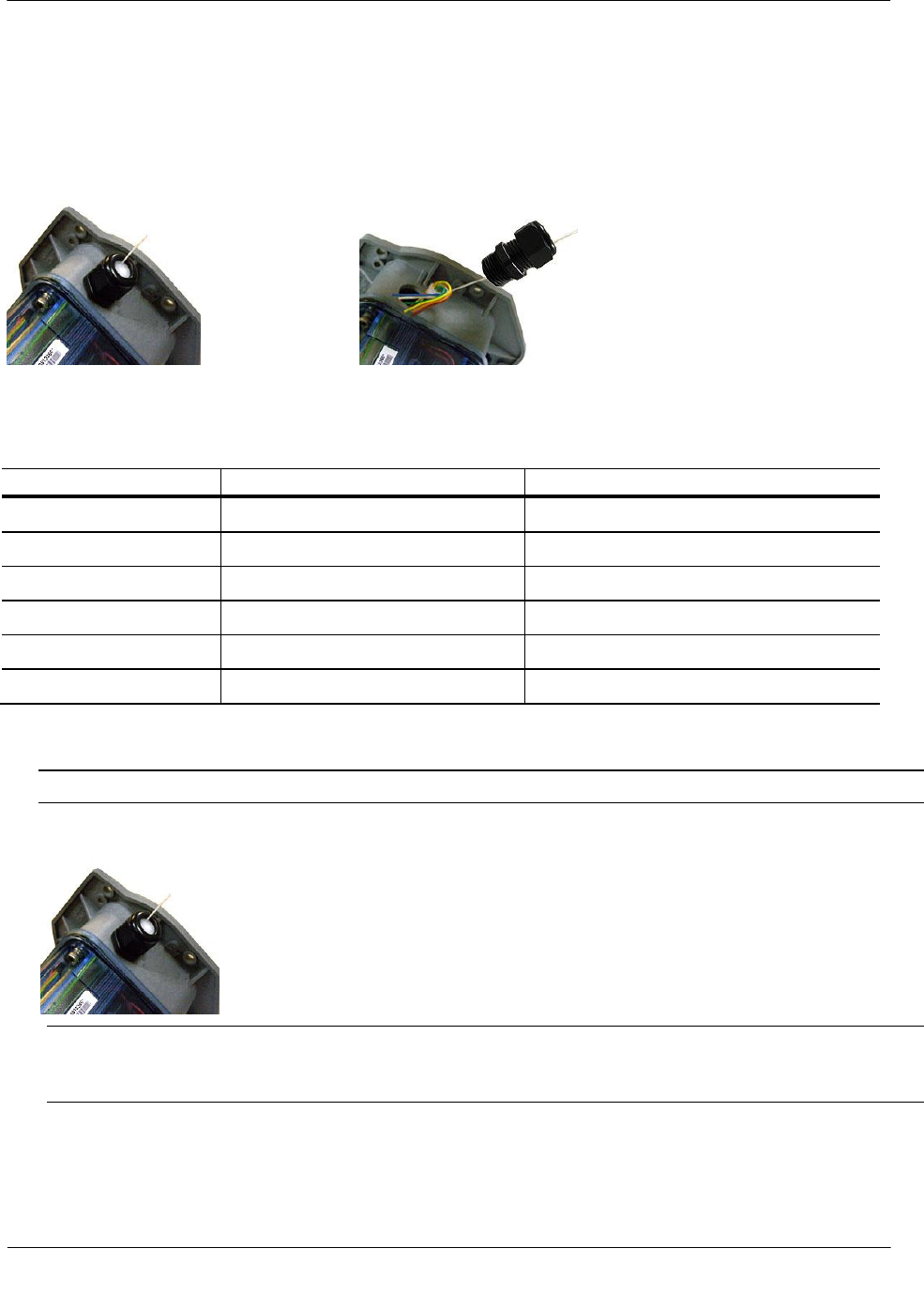
1. Insert the ERT module cable into the instrument's compression connector.
2. Strip one inch of the outer insulation from the 100G Datalogging FN remote ERT module. Strip 1/4-inch
individual wire insulation from the red, white, and blue lead wires.
A White wire
B Blue wire
C Red wire
Caution Keep wires away from the rotating magnetic spindle in the Mercury Instrument.
Electronic Volume Corrector and Instrument Installation
TDC-0824-003 100G Datalogging FN ERT Module Installation Guide - Remote Mount 38
Proprietary and Confidential
3. See Mounting the 100G Datalogging FN Remote ERT Module on page 6 for module mounting
instructions.
Wiring Dual ERT Modules to a Mercury Instrument
This section includes the information to wire dual ERT modules to a single Mercury Instrument. Installation
requires the correct programming parameters (see Code Settings on page 35).
With Itron 100G Datalogging FN remote ERT modules, utilities can receive corrected and uncorrected
consumption values by installing two endpoints. The ERT module for corrected reads is attached to the
corrector's pulse output. The ERT module for uncorrected reads is attached to the input switch board. The
corrected pulse output is programmable; the uncorrected pulse output is dependent on the connected meter's
drive rate.
Important Some Mercury Instruments have two pulse outputs so the uncorrected pulse output
could be connected to the additional output, but the connection should be to the input switch
board in case the corrector battery fails. Counts will be collected if the uncorrected pulse is
connected to the switch board since the board is not dependent on battery power.
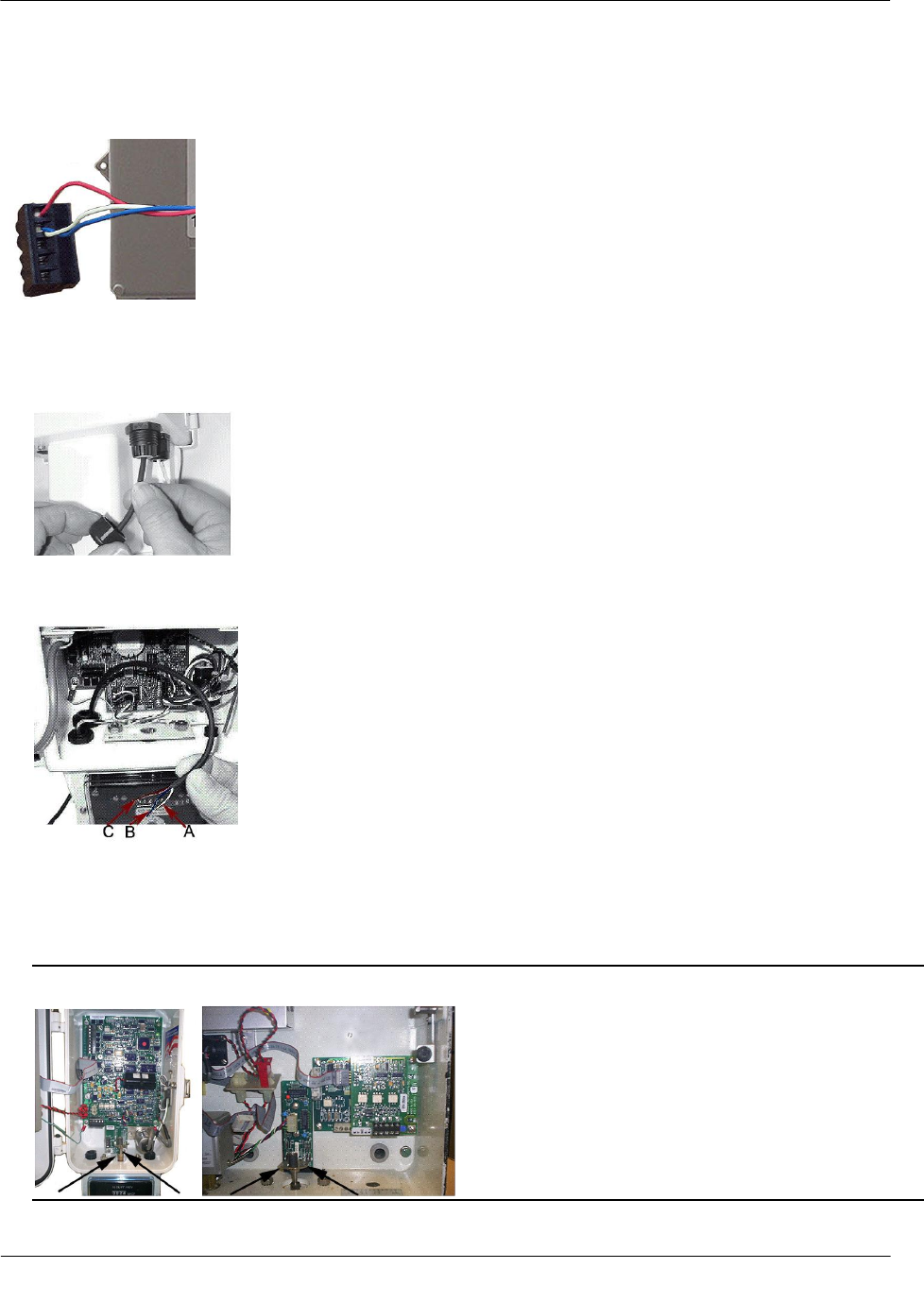
Dual Remote ERT Modules Mounted on a Mercury Instrument
To install dual 100G Datalogging FN remote ERT modules to a Mercury Instrument Mini-Max
Case Volume Corrector using Mercury Kit 22-1077
1. Place the Mercury Instrument volume corrector in shutdown condition and disconnect all power from the
Mini-Max main board.
2. Remove the battery pack from the volume corrector and set it aside.
3. Remove the four screws from the main board and the board from the enclosure. Set the board aside.
4. Remove the two hex screws from the input switchboard and the switchboard from the enclosure and set it
aside. You will re-install the switchboard later.
Warning The battery pack, main board and switchboard may be damaged if left in the Mercury
Instrument volume corrector while completing this installation.

Electronic Volume Corrector and Instrument Installation
TDC-0824-003 100G Datalogging FN ERT Module Installation Guide - Remote Mount 39
Proprietary and Confidential
5. Drill two 3/16-inch holes in the back of the Mini-Max enclosure as specified by the information included
in the kit. Remove any metal shavings from the enclosure.
6. Clean the 100G Datalogging FN remote ERT modules with the alcohol wipe where you will place the
Corrected and Uncorrected labels (included in the kit).
Note Clean the Datalogging FN remote ERT modules with the alcohol wipe to ensure good label
adhesion.
7. Mount the module for corrected pulse outputs on the left bracket mounting space. Insert three #8-32 x 1/2-
inch screws in a triangular pattern. Install the top screw so the head of the screw is approximately 1/8-inch
from the Endpoint Mounting Bracket surface. Slide the module onto the screw so the mounting lug fits
securely onto the screw. If necessary, remove the module and make any necessary adjustment to the screw
depth to ensure a secure fit. Install the two bottom screws in an alternating fashion.
8. Mount the module for uncorrected pulse outputs on the right bracket mounting space. Insert three #8-32 x
1/2-inch screws in a triangular pattern. Install the top screw so the head of the screw is approximately 1/8-
inch from the Endpoint Mounting Bracket surface. Slide the endpoint onto the screw so the mounting lug
fits securely onto the screw. If necessary, remove the module and make any necessary adjustment to the
screw depth to ensure a secure fit. Install the two bottom screws in an alternating fashion.
9. Route the module cables under the bracket edge and toward the rear of the Mercury Instrument.
10. Mount the Endpoint Mounting Bracket (Mercury Instrument part number 22-1077, included in the kit)
onto the Mini-Max enclosure. Place a #8 metal flat washer followed by a rubber sealing washer onto both
#8-32 x 3/8" screws. Align the lower threaded holes in the mounting bracket with the drilled enclosure
holes and insert a screw/washer through the enclosure housing. Screws heads must be inside the enclosure.
Tighten both screws using a screwdriver.
Note Aligning the second bracket threaded hole and drilled hole may require some manipulation of the
mounting bracket.
11. Insert the module cables (both units) through the large cable strain relief on the left rear of the instrument's
enclosure. Leave a one-half to one inch drip loop under the cable strain relief.
12. Secure three cable ties on the module cables in three places on the cables as specified by information
included in the kit.
13. Re-install the input switchboard, main board, and battery pack removed in step 2.
14. Connect the corrected module wires to TB1 on the Mini-Max board following the table below. Use
Mercury upgrade kit 40-2678-1 to provide the second pulse output channel for the uncorrected ERT
module.
Corrected ERT Module Connections
ERT Module
Mini-Max TB1
Red wire
K terminal
Blue wire*
Ya terminal
White wire*
Ya terminal
*Twist the blue and white endpoint wires together before connecting to the Mini-Max board.
Tighten terminal connections securely.
Electronic Volume Corrector and Instrument Installation
TDC-0824-003 100G Datalogging FN ERT Module Installation Guide - Remote Mount 40
Proprietary and Confidential
15. Connect the uncorrected module wires to the Input Switch Board UNC. VOL following the table below.
Uncorrected ERT Module Connections
ERT Module
Mini-Max Input
Switch Board UNC. Vol.
Red wire
COM terminal
Blue wire*
NO terminal
White wire*
NO terminal
*Twist the blue and white ERT module wires together before connecting to the Mini-Max board.
Tighten terminal connections securely.
16. Tighten the large strain relief securely.
Warning Do not crush the endpoint through-cables when tightening the strain relief.
17. Re-install or reconnect the power or battery sources.
18. Close the instrument case and tighten the case screw securely. Replace any locks that were removed for
installation.
Wiring the Remote ERT Module to the Mercury TCI
The Mercury Instruments Temperature Compensating Index (TCI) provides two Form-A volume pulse
outputs and one Form-B alarm output. These outputs are electronic switches. The first two pulse outputs are
configurable for compensated or uncompensated volume. The third output (Form-B) is for alarm output use
only.
Electronic Volume Corrector and Instrument Installation
TDC-0824-003 100G Datalogging FN ERT Module Installation Guide - Remote Mount 41
Proprietary and Confidential
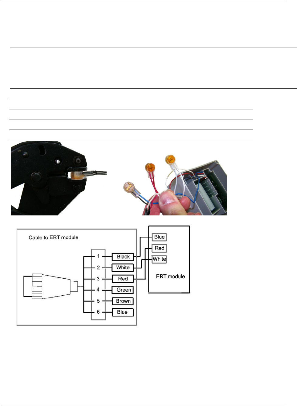
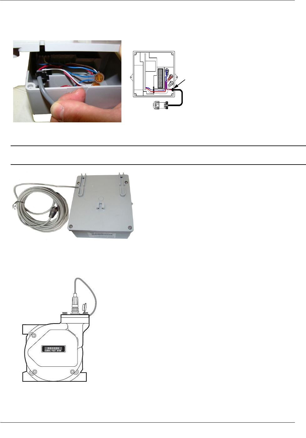
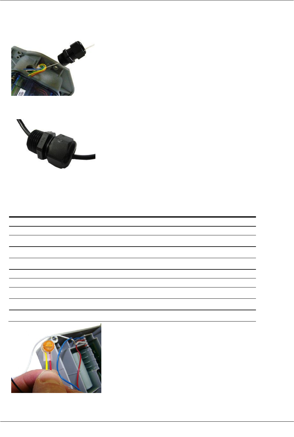
Connections to the three output pulse channels are completed using loose unterminated wires (the individual
wires from a cable) and gel-connectors. The TCI unit has six unterminated wires and six gel-connectors (Itron
part number CON-0023-001) to enable pulse connections to ancillary devices. Loose wires are located inside
the gray adapter plate behind the black strain relief fitting.
Adapter plate with black strain relief Loose cable wires
The three switch contacts on the TCI PC board are MOSFET output type opto-isolators that provide high
voltage isolation between the sensitive processor components of the TCI board and the outside world.
Wire Color
Description
Function
Orange
Volume output channel A
Comp/uncomp volume pulse
Yellow
Volume output channel A
(configurable pulse timing)
White
Volume output channel B
Comp/uncomp volume pulse
Green
Volume Output channel B
(configurable pulse timing)
Brown
Alarm channel
Alarm event signal
Blue
Alarm channel
(Pulse timing)
To make TCI pulse connections
Note Connect one ERT module/channel to the alarm output if the modules are used on channels A and B.
1. Remove strain relief fitting by unscrewing from the gray adapter plate.
Note Do not remove the fitting's hex nut. Un-screw the entire fitting from the gray adapter plate. A
tether line is secured to the strain relief fitting. When the strain relief fitting is removed, the tether line
pulls the unterminated wires out of the adapter plate for access to the loose wires.
2. Loosen the strain relief fitting hex nut and remove the white plug from the center.
Electronic Volume Corrector and Instrument Installation
TDC-0824-003 100G Datalogging FN ERT Module Installation Guide - Remote Mount 42
Proprietary and Confidential
3. Place the strain relief fitting onto the field pulse cable.
4. If the field pulse cable is smaller than a 0.2-inch diameter, install the rubber tube supplied with the TCI
onto the cable so the strain relief will clamp onto the tube after it is re-installed.
5. Connect the individual external pulse cable conductors to the un-terminated wires following
Configuration for two endpoints connected to one TCI. Insert one un-terminated wire into an opening of a
gel-connector (six gel-connectors were included with the TCI). Insert the appropriate field cable wire into
the other gel-connector opening.
Configuration for two ERT modules connected to one TCI
Channel A
ERG-500x-503
TCI
White
Orange and brown
Red
Yellow
Blue
Blue (alarm)
Channel B
ERG-500x-503
TCI
White
White
Red
Green
Blue
White
Electronic Volume Corrector and Instrument Installation
TDC-0824-003 100G Datalogging FN ERT Module Installation Guide - Remote Mount 43
Proprietary and Confidential
6. Verify both wires are fully inserted into the gel-connector prior to crimping.
Important Use a crimping tool compatible with gel-connectors. Do not use a standard pliers for crimping
gel-connects. The crimping tool provides an even pressured crimp to make a secure connection. Apply
pressure for three seconds until the gel cap is fully crimped (collapsed) to allow time for the low viscosity
silicone-based gel to flow. If the silicone gel flows out of the crimped connector, avoid touching the gel.
Gel flowing from the connector provides environmental protection for the connection.
7. Insert the gel-connected wires into the threaded gray adapter plate hole.
8. Replace the strain relief and tighten until secure.
Connecting the 100G Datalogging FN Remote Mount ERT
Module to the IMC/W2 or MC2 Cable
You may ship the Itron 100G Datalogging FN remote ERT module directly to Dresser ROOTS® Meters for a
factory-installed cable. If you connect the ERT module to the meter using an existing cable purchased from
Dresser ROOTS®, complete the following cable installation procedure.
Caution The purchased cable must have a mating connector compatible with the IMC/W2 or MC2
receptacle. Dresser ROOTS® cables may be wired in different configurations for specific
applications. If necessary, contact Dresser ROOTS® Meters for wiring diagrams for your specific
application.
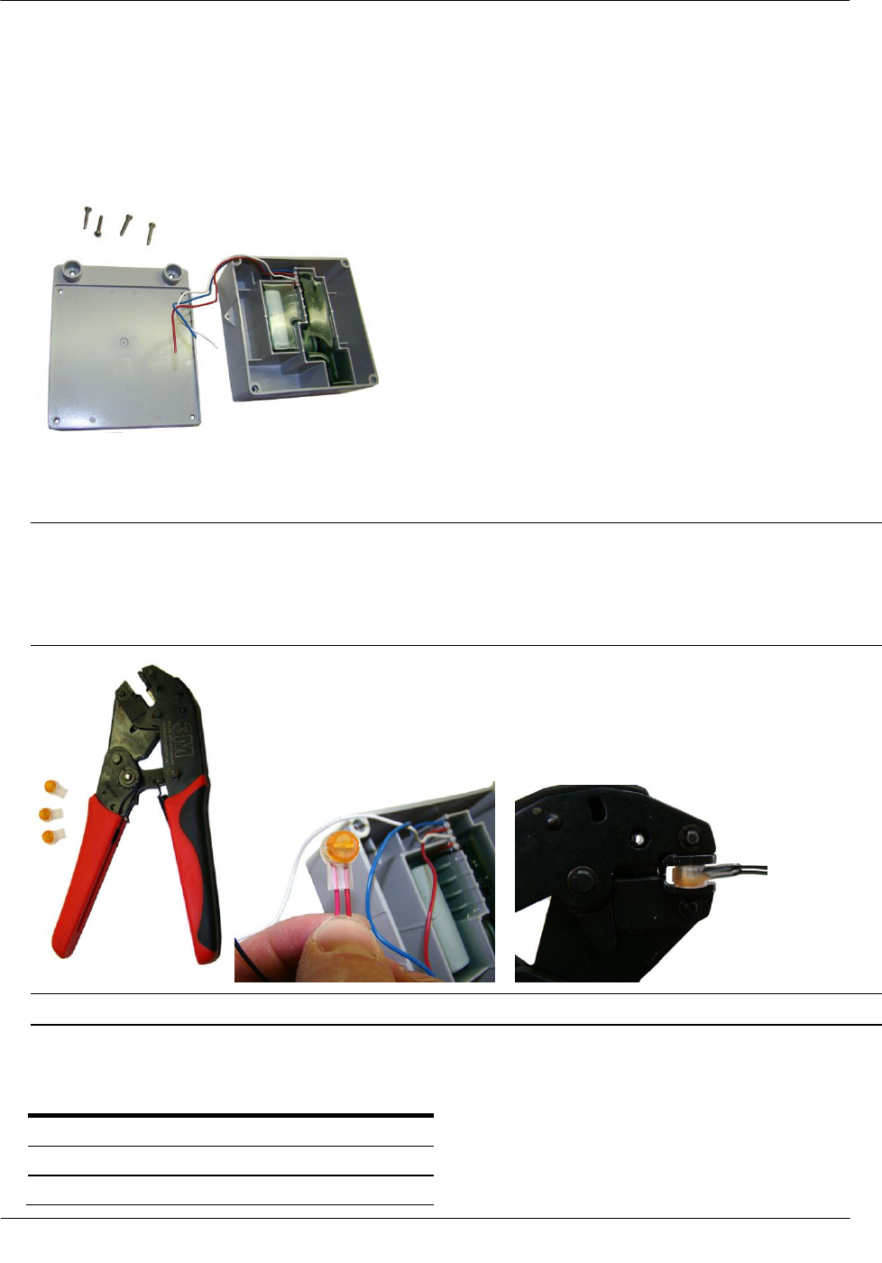
Electronic Volume Corrector and Instrument Installation
TDC-0824-003 100G Datalogging FN ERT Module Installation Guide - Remote Mount 44
Proprietary and Confidential
To connect the 100G Datalogging FN remote ERT module to the IMC/W2 or MC2 cable
1. Remove the backplate (4 screws) from the 100G Datalogging FN remote ERT module and expose the
module lead wires. The backplate and screws will be re-installed on the module later in this procedure so
store them (temporarily) in a safe, secure place.
2. Insert the lead wires from the 100G Datalogging FN remote ERT module into new 3M gel connectors
(Itron part number CON-0023-001) together with the same colored lead wire from the meter cable (see the
wiring table below) and crimp using a 3M hand-held crimping tool.
Important Use a crimping tool compatible with gel-connectors. Do not use a standard pliers for crimping
gel-connects. The crimping tool provides an even pressured crimp to make a secure connection. Apply
pressure for three seconds until the gel cap is fully crimped (collapsed) to allow time for the low viscosity
silicone-based gel to flow. If the silicone gel flows out of the crimped connector, avoid touching the gel.
Gel flowing from the connector provides environmental protection for the connection.
Note Do not strip lead wire prior to inserting the wire in the gel connector.
IMC/W2 to Remote ERT Module Wire Table
IMC/W2 Wire
Remote Module wire
Red
Red
White
White
Blue
Blue