Itron 100GR Spread Spectrum Device User Manual
Itron, Inc. Spread Spectrum Device Users Manual
Itron >
Users Manual

Natural Gas Solutions
100G Installation Guide for Mercury
Electronic Volume Correctors
Revision A3
Natural Gas Solutions
DRAFT

Identification
100G Remote ERT Module Installation Guide
Part number: PUB-0200-002 Revision A 02/08
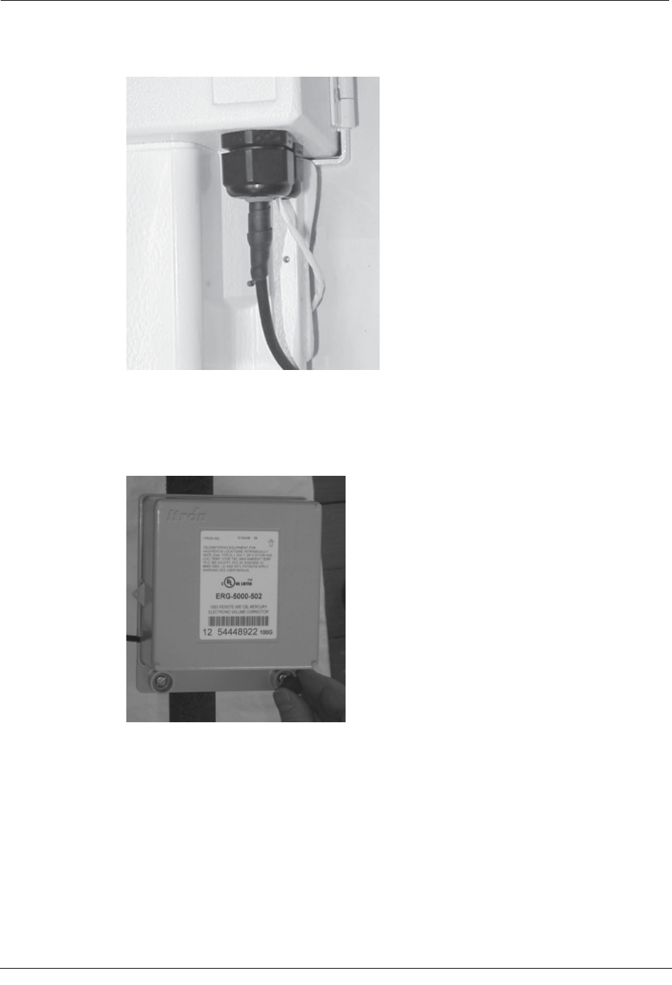
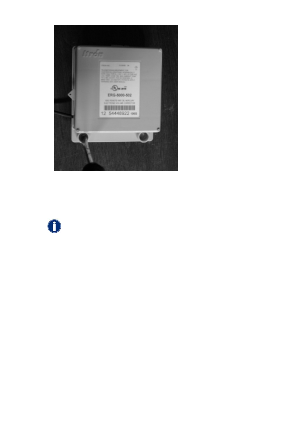
ERT Part Numbers: ERG-5000-502 (100G with 5-ft. cable)
Copyright
© 2008 Itron, Inc. All rights reserved.
Your company has the right to reproduce this contract document, provided that such reproduction shall be subject to the same use and disclosure restrictions contained in the
Confidentiality and Non-Disclosure paragraphs in the Sales Contract.
Applicable Patents
U.S. Patent Numbers: TBD
Canadian Patent Numbers: TBD
Transportation Classification
The Federal Aviation Administration prohibits operating transmitters and receivers on all commercial aircraft. When powered, the 100G Remote ERT Module is considered an operating
transmitter and receiver and cannot be shipped by air. All product returns must be shipped by ground transportation.
WARNING! Only authorized Itron personnel should attempt repairs on Itron
equipment. Attempts to do so by others might void any maintenance contract
with your company. Unauthorized service personnel might also be subject to
shock hazard on some Itron equipment if removal of protective covers is
attempted.
WARNING! Substitution of components may impair intrinsic safety.
WARNING! To prevent ignition of flammable or combustible atmospheres,
disconnect power before servicing.
Compliance Statement
This device complies with Part 15 of the FCC Rules. Operation of this device is subject to the following two conditions:
• This device may not cause harmful interference.
• This device must accept any interference that may cause undesirable operation.
This device must be permanently mounted such that it retains a distance of 20 centimeters (7.9 inches) from all persons in order to comply with FCC RF exposure levels.
Modification and Repairs
To ensure FCC compliance and system performance, this device and antenna shall not be changed or modified without the expressed approval of Itron. Any unauthorized modification
will void the user’s authority to operate the equipment.
Meter Installation/Removal
In the event of malfunction, all repairs should be performed by Itron. It is the responsibility of users requiring service to report the need for service to Itron.
WARNING! Follow these procedures to avoid injury to yourself or
others.
• The lithium battery may cause a fire or chemical burn if it is
not disposed of properly.
• Do not recharge, disassemble, heat, or incinerate the lithium
battery.
• Keep the lithium battery away from children.
Related Documents
Endpoint-Link Endpoint Programming Guide (TDC-0744)
Trademark Notice
Enscan, ERT, Itron, ReadOne, and Endpoint-Link are registered trademarks of Itron, Inc. All other product names and logos in this documentation are used for identification purposes
only and may be trademarks or registered trademarks of their respective companies.
Suggestions
If you have comments or suggestions on how we may improve this documentation, send them to TechnicalCommunicationsManager@itron.com.
If you have questions or comments about this application, contact Itron Technical Support:
Itron, Inc.
• Mail: Itron, Inc. Attention: Customer Care, 2111 N Molter Road, Liberty Lake, WA 99019
• E-mail: support@itron.com
• Phone: 1 800 635 8725
DRAFT

Contents
Chapter 1 Getting Started...........................................................................................1
Tools and Materials Supplied By You .................................................................................................1
Materials Supplied by Itron..................................................................................................................2
Screw Specifications.................................................................................................................3
Code Settings......................................................................................................................................3
Chapter 2 Installing the 100G Remote ERT Module ..................................................7
Mount the Corrector ............................................................................................................................7
Pipe Mounting .....................................................................................................................................8
Adapter Plate Mounting Positions...........................................................................................12
Program the ERT ....................................................................................................................15
Flat Surface Mounting .......................................................................................................................22
Program the ERT ....................................................................................................................25
Functional Specifications...................................................................................................................30
Physical Specifications......................................................................................................................31
Operational Specifications.................................................................................................................31
Natural Gas Solutions 100G Installation Guide for Mercury Electronic Volume Correctors iii
DRAFT

Contents
iv Natural Gas Solutions 100G Installation Guide for Mercury Electronic Volume Correctors
DRAFT
CHAPTER 1
Getting Started
The 100G is Itron's latest gas encoder-receiver-transmitter (ERT®) module.
ERT modules are radio-frequency (RF) devices that transmit meter data. The RF meter data
can be received by a reading device that is within transmission distance of the ERT. Itron's
100G ERT module has increased output power over legacy gas ERT modules for increased
RF transmission distance.
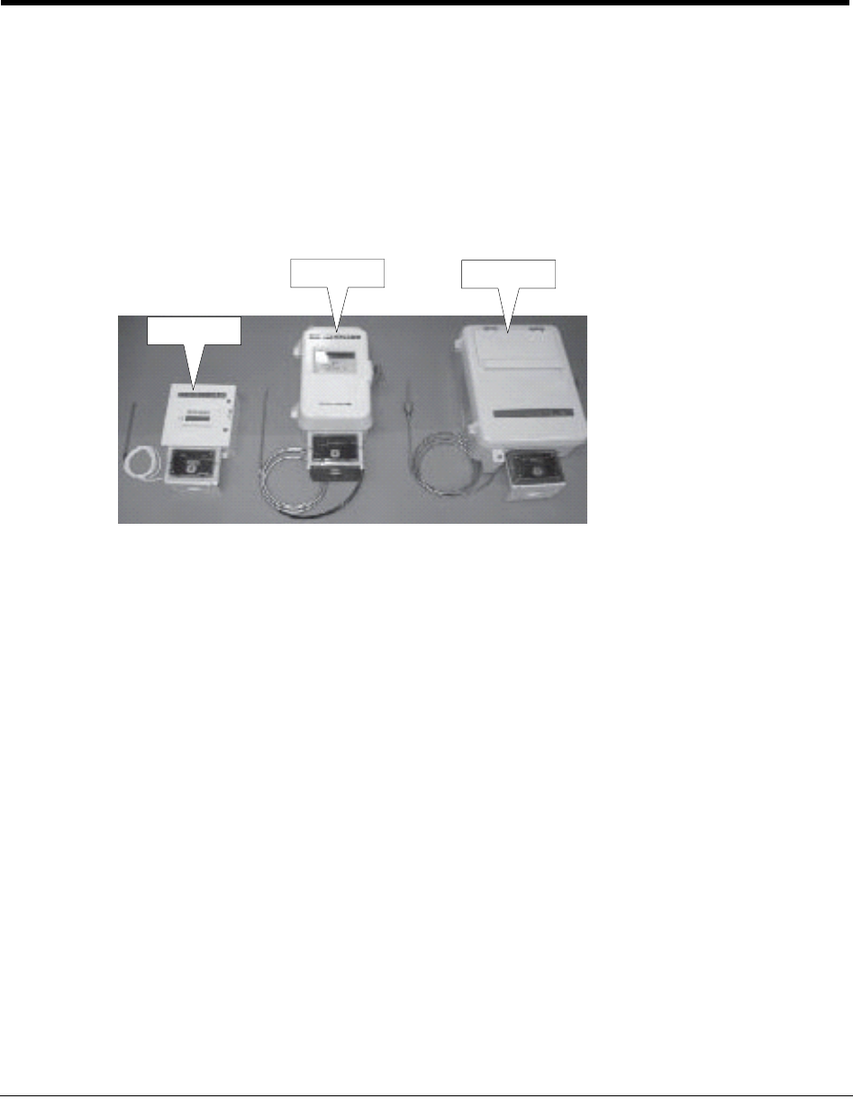
This installation guide shows you how to install the 100G Remote ERT Module on the
Mercor Mini, Mini-AT, Mini-Max, and EC-AT meter correctors.
Mini-Max
Mini-AT EC-AT
Tools and Materials Supplied By You
You must supply the following tools and material to install, program, and check the 100G
Remote ERT Module:
• Medium flat-blade screwdriver for band clamps
• Small flat-blade screwdriver for installing Phoenix connector
• Medium flat-blade, torque-measuring screwdriver for the screws used to attach
adapter plates to pipe brackets and the screws used to attach ERT modules to adapter
plates. Torque to be measured is 9 to 12 inch-pounds
• Medium Philips screwdriver for opening and closing Mini-Max cover, and, if
necessary, for attaching ERT modules to flat surfaces
• Pliers for pulling cable ties tight
• 1" wrench for tightening compression connector nut
• Side-cutting pliers ("dykes") or similar tool for cutting off the excess length of cable
tie straps
• 1/4-inch nut driver or other blunt tool for seating ERT-module tamper seals
• Rubber tape for sealing compression connector
Natural Gas Solutions 100G Installation Guide for Mercury Electronic Volume Correctors 1
DRAFT
Chapter 1 Getting Started
• FC200R unit for programming and checking ERT modules.
Materials Supplied by Itron
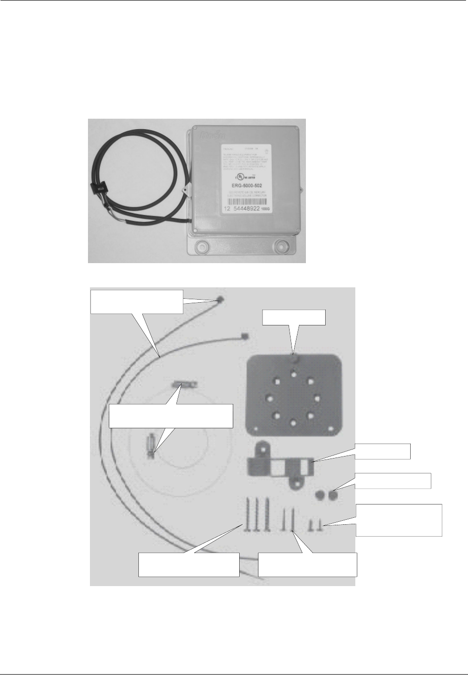
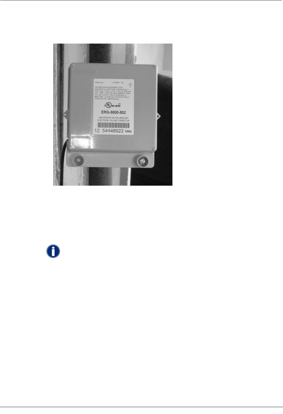
The following items are supplied with each 100G Remote ERT Module installation:
• 100G Remote ERT Module with 5-foot cable (ERG-5000-502)
• A pipe bracket installation kit
Pipe bracket
Two tamper seals
Adapter plate
Two screws to attach
the adapter plate to
the pipe bracket
Three screws to attach
the ERT to a flat surface Two screws to attach the
ERT to the adapter plate
Two band clamps for attaching
the pipe bracket to a pipe
Two cable ties for
securing the ERT cable
2 Natural Gas Solutions 100G Installation Guide for Mercury Electronic Volume Correctors
DRAFT
Code Settings
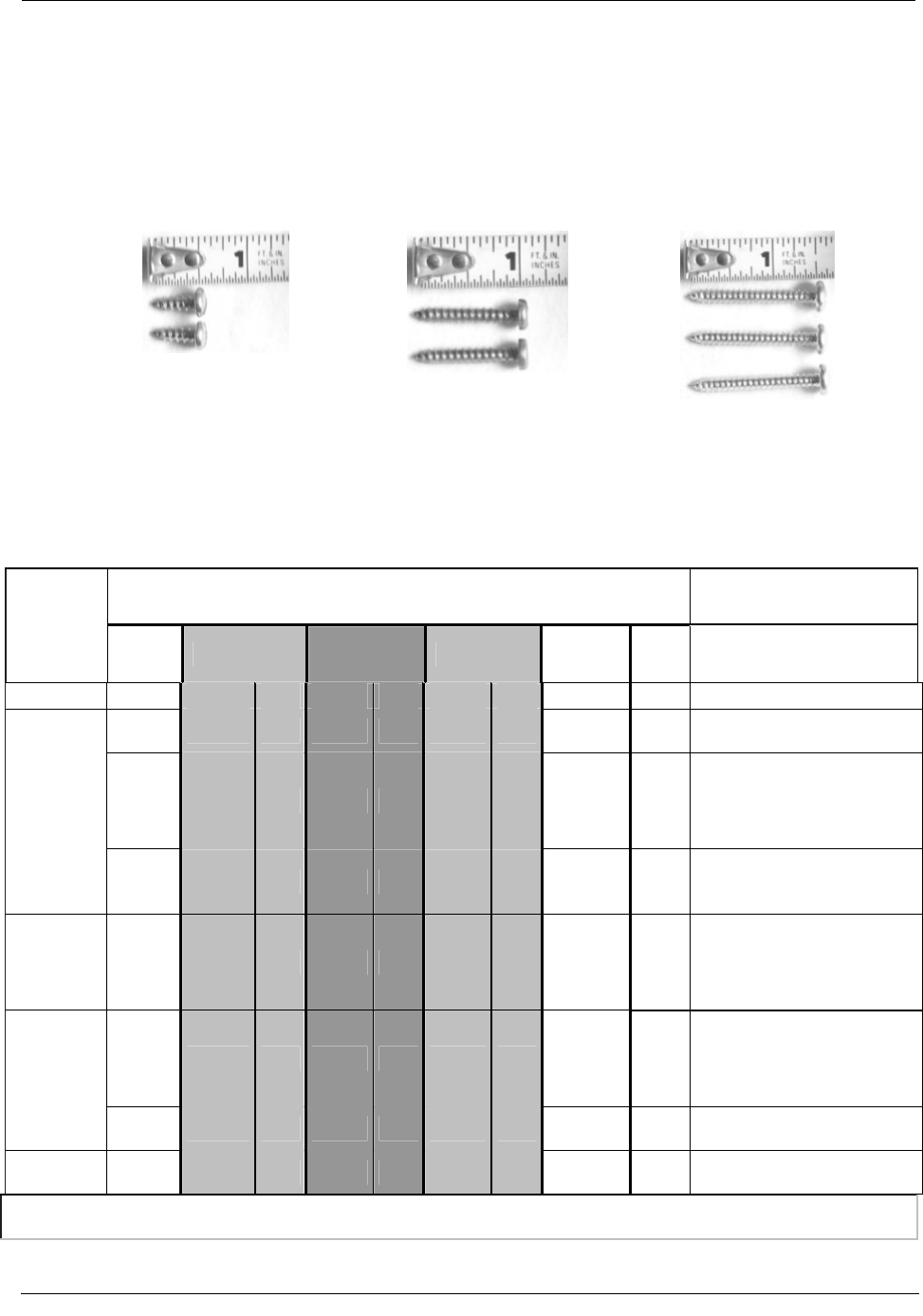
Screw Specifications
For mounting adapter plates on
pipe brackets For mounting ERTs on adapter
plates For mounting ERTs on wood or
sheet metal surfaces
8–15 x 1/2 Type A slotted pan
head tapping screw,corrosion
resistant steel
8–15 x 1 Type A slotted panhead
tapping screw, corrosion resistant
steel
10–16 x 1 1/2 Type AB Phillips
panhead tapping screw, corrosion
resistant steel
Code Settings
Item Code Settings and Corresponding Terminal Board Channel Terminal Board Connections*
Instrument
Type
Form A Channel A Channel B Channel C
Ka, Ya = Channel A Kb, Yb =
Channel B Kc, Yc = Channel C
#056 #093 #057 #094 #058 #095 #096 #115
0 n/a n/a n/a n/a n/a n/a n/a n/a ERT does not support a Form-C
Pulse Output Board
3 2.0000 0 2.0000 0 2.0000 0 1, 2, 3 or 4 1 or 2
Ka, Kb, Kc (Red Wire) Ya, Yb, Yc
(Blue & White Wire). Connection
must be on same terminal board
channel (i.e., Ka/Ya; Kb/Yb;
Kc/Yc).
ECAT:
1 n/a n/a n/a n/a 2.0000 0 1, 2, 3 or 4 1 or 2 Kc (Red Wire) Yc (Blue & White
Wire) For this option, ERT must be
connected to Channel C.
Mini with
Form A
Mainboard: 1 2.0000 0 n/a n/a n/a n/a 1, 2, 3 or 4 1 or 2
K (Red Wire) Y (Blue & White
Wire) Jumper settings must be on
J1-B as stated in the Mercury Quick
Reference Guide (page 45) for
Form-A.
2 2.0000 0 2.0000 0 n/a n/a 1, 2, 3 or 4 1 or 2
K (Red Wire) Y (Blue & White
Wire) Jumper settings must be on
J1-B as stated in the Mercury Quick
Reference Guide (page 45) for
Form-A.
Mini-AT:
0 n/a n/a n/a n/a n/a n/a n/a n/a ERT does not support a Form-C
Pulse Output Board
Mini-Max: 2 2.0000 0 2.0000 0 n/a n/a 1, 2, 3 or 4 1 or 2 K (Red Wire) Ya OR Yb (Blue &
White Wire)
* For more information, see pages 11-20 of the "Basic Pulse Information for Mercury Instruments, Inc., Electronic Volume Correctors" manual, or
contact Mercury Instruments at 513-272-1111.
Natural Gas Solutions 100G Installation Guide for Mercury Electronic Volume Correctors 3
DRAFT

Chapter 1 Getting Started
4 Natural Gas Solutions 100G Installation Guide for Mercury Electronic Volume Correctors
DRAFT

Code Settings
Natural Gas Solutions 100G Installation Guide for Mercury Electronic Volume Correctors 5
DRAFT
DRAFT
CHAPTER 2
Installing the 100G Remote ERT Module
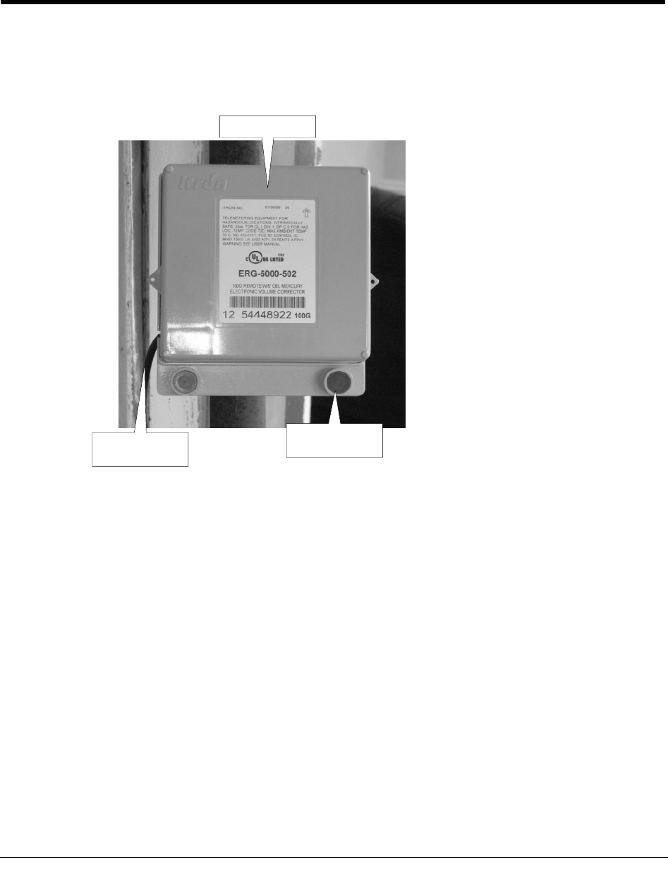
The 100G Remote ERT Module can be mounted on a pipe, using the pipe bracket
installation kit, or a flat surface. The 100G Remote ERT Module must always be mounted
with the printed label right-side-up, and the encoder wires and tamper seals at the bottom, as
shown.
Top of ERT
Cable comes
out the bottom
Tamper seals at
the bottom
Mount the Corrector
Mount the corrector on the meter according to the Mercury installation manual.
Enter the specified code settings for the corrector.
Natural Gas Solutions 100G Installation Guide for Mercury Electronic Volume Correctors 7
DRAFT
Chapter 2 Installing the 100G Remote ERT Module
Pipe Mounting
To mount the adapter plate on vertical a pipe
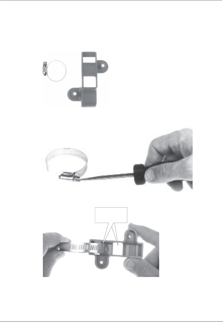
1. Get the pipe bracket from remote mount kit and a proper size band clamp.
2. Loosen the clamp screw until the end of the band is released.
3. Push the end of the band through this hole in the pipe bracket.
Pass end of
band clamp
through the hole
8 Natural Gas Solutions 100G Installation Guide for Mercury Electronic Volume Correctors
DRAFT
Pipe Mounting
4. Place the band clamp around the pipe.
5. Push the end of the band through the hole in the band clamp and into the entrance to
the screw assembly.
Pass end of the band
through this hole
Entrance to screw
assembly
6. Tighten the band clamp until the end of the band can be pushed into the hole in the
pipe bracket.
Put the end of
the band in this
hole
Natural Gas Solutions 100G Installation Guide for Mercury Electronic Volume Correctors 9
DRAFT
Chapter 2 Installing the 100G Remote ERT Module
7. Tighten the clamp screw three or four more turns to make sure the end of the band
does not pop back out on this side of the pipe bracket.
8. Position the band clamp as shown then fully tighten the band clamp screw.
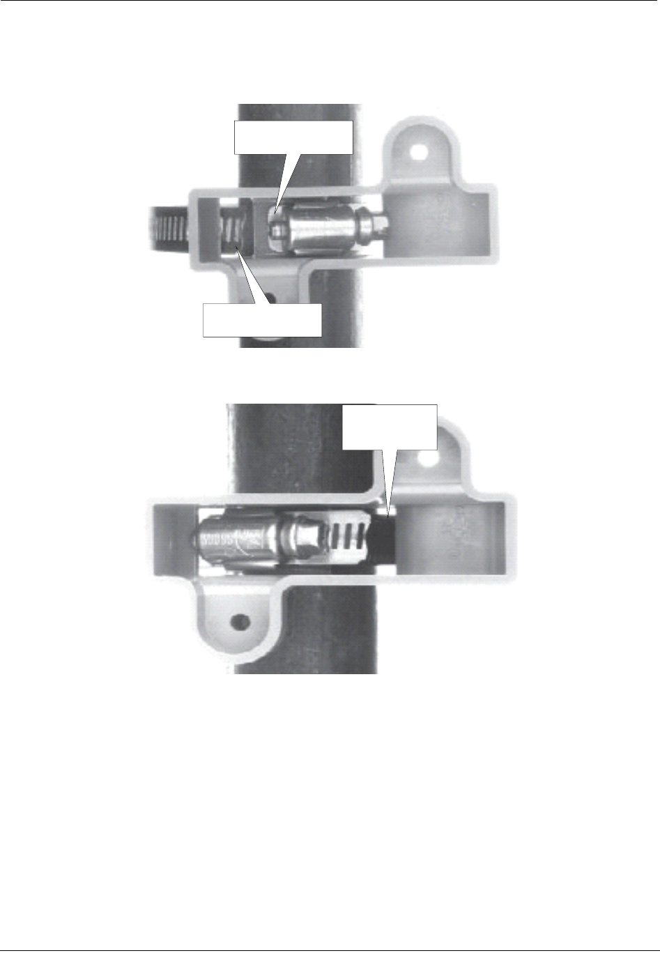
9. Place the adapter plate on the pipe bracket. The adapter-plate screw boss goes into this
pipe-bracket recess.
Screw boss
Screw boss
10 Natural Gas Solutions 100G Installation Guide for Mercury Electronic Volume Correctors
DRAFT
Pipe Mounting
When the adapter plate is properly positioned on the pipe bracket, it looks like this.
10. Obtain two adapter-plate mounting screws (shown here actual size) from the
installation kit.
11. Install the adapter plate mounting screws in these holes.
Put screws in
these holes
12. Tighten both screws to 9 to 12 inch-pounds of torque.
Natural Gas Solutions 100G Installation Guide for Mercury Electronic Volume Correctors 11
DRAFT
Chapter 2 Installing the 100G Remote ERT Module
Adapter Plate Mounting Positions
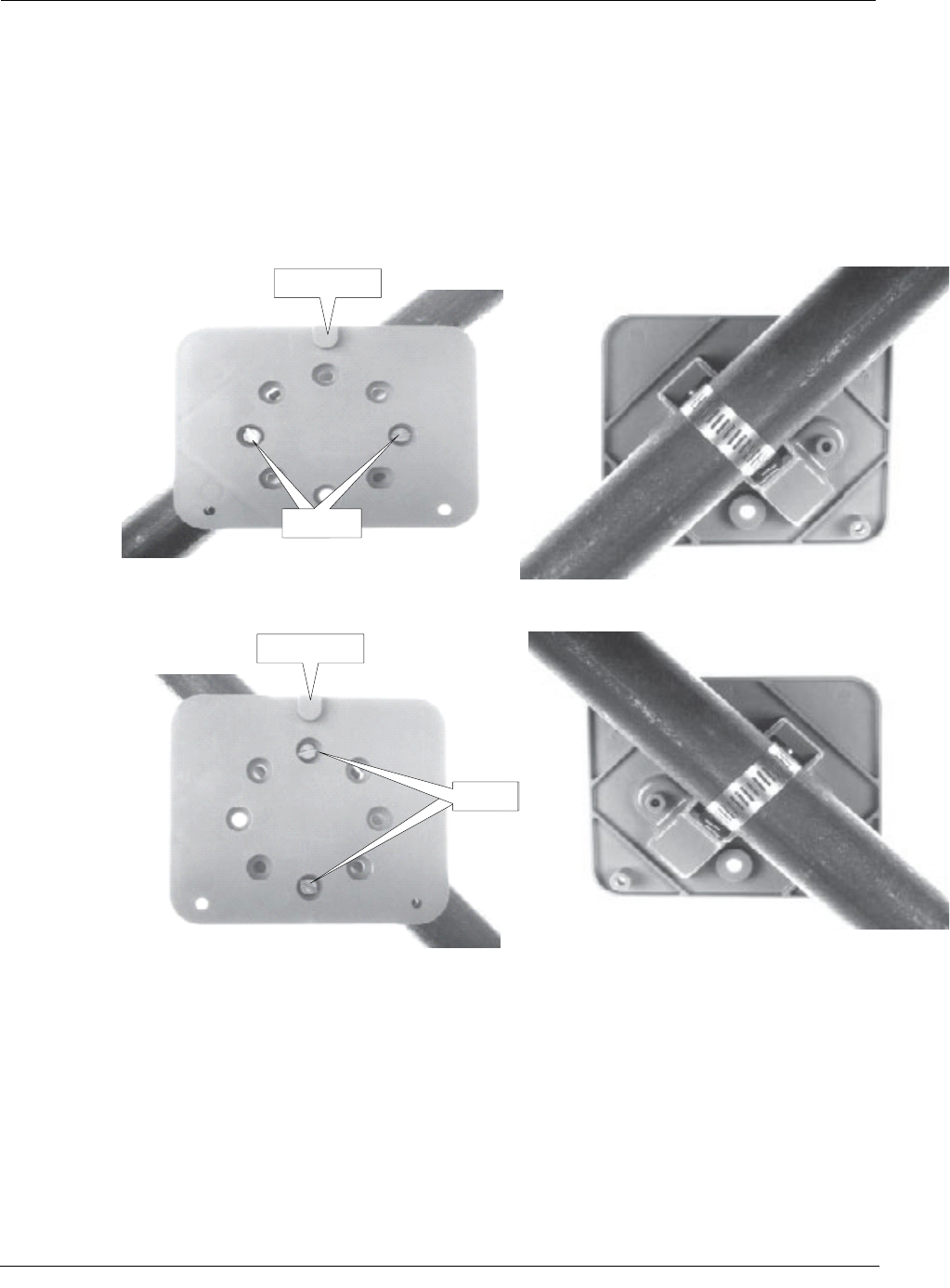
The installation procedure in this section shows how to mount the adapter plate on vertical
pipes. The following pictures show how to mounting the adapter plate on pipes that are
either horizontal or at 45 degree angles. Regardless of which direction the pipe goes, the
adapter plate mounting lug must always be at the top.
If the pipe is at a 45 degrees angle up to the right, install the adapter plate as shown.
Mounting lug
Screws
If the pipe is at a 45 degrees angle up to the left, install the adapter plate as shown.
Mounting lug
Screws
If the pipe is horizontal, install the adapter plate as shown.
12 Natural Gas Solutions 100G Installation Guide for Mercury Electronic Volume Correctors
DRAFT
Pipe Mounting
Mounting lug
Screws
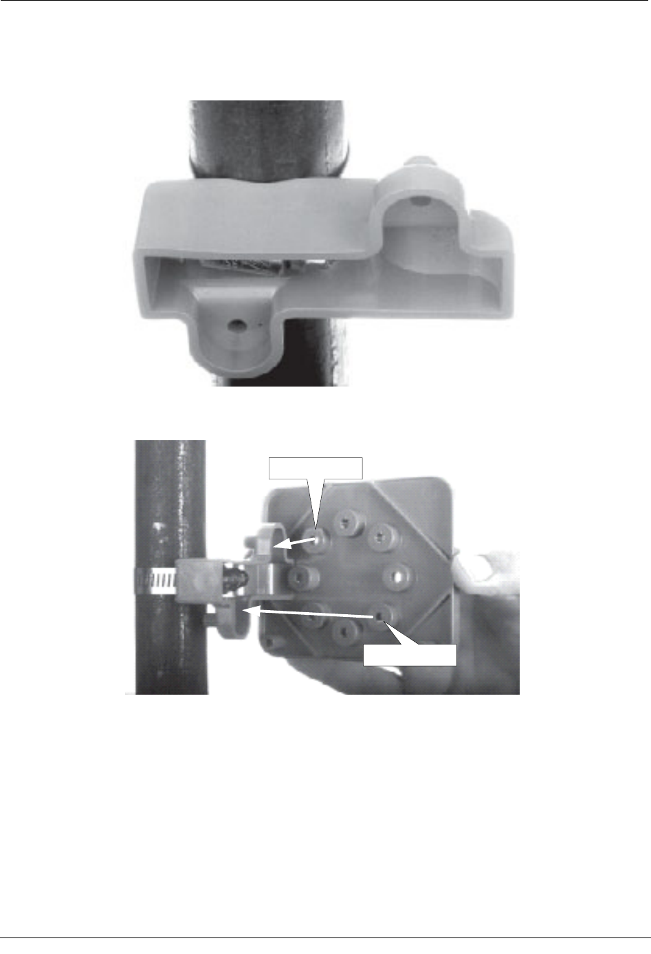
To mount the 100G Remote ERT Module on the adapter plate
1. Get the 100G Remote ERT Module and two 1-inch mounting screws from the
installation kit.
2. Place the back of the ERT module against the face of the adapter plate.
Natural Gas Solutions 100G Installation Guide for Mercury Electronic Volume Correctors 13
DRAFT
Chapter 2 Installing the 100G Remote ERT Module
The adapter-plate mounting lug should be just above the ERT-module mounting lug
recess.
Mounting lug
Mounting lug
recess
3. Raise the ERT module until the adapter-plate mounting lug is as far as possible inside
the ERT-module mounting lug recess.
14 Natural Gas Solutions 100G Installation Guide for Mercury Electronic Volume Correctors
DRAFT
Pipe Mounting
4. Install the two ERT module mounting screws you got from the installation kit.
When the ERT module is properly mounted on the adapter plate, it should look like
this.
5. Tighten the screws to 9 to 12 inch-pounds of torque.
Program the ERT
The ERT must be programmed using the FC200SR with EndPoint-Link software. See the
Endpoint-Link ERT Programming Guide (TDC-0411) for more information.
IMPORTANT You must perform the following programming procedure for
the ERT module to function properly.
When programming the ERT module, you must take note of the drive rate shown on the
index of the meter. Program the meter based on the drive rate shown on the index.
Natural Gas Solutions 100G Installation Guide for Mercury Electronic Volume Correctors 15
DRAFT
Chapter 2 Installing the 100G Remote ERT Module
To program the ERT module
1. Using the FC200SR, program the reading of the index that was on the meter into the
ERT module assembly.
• For initial programming, hold the FC200SR approximately 1 foot away from
the 100G.
• For reprogramming (30 days or more past initial programming), hold the
FC200SR approximately 4 to 5 feet away from the 100G.
Be sure to program the 100G to the correct mode for the reading technology that will
be used (for example, Fixed Network Mode, Mobile/Handheld Mode, or Hard to Read
Mobile/Handheld Mode). In Endpoint-Link Pro v5.0, you will have access to the one
mode that was defined by your system administrator.
2. Read the ERT module assembly using the FC200SR. Consult the EndPoint-Link ERT
Programming Guide (TDC-0411) or other applicable instructions for details on how to
read an ERT.
• If this reading is higher than the one you programmed in step 1 above, the ERT
module assembly is counting correctly.
• If the ERT module assembly reading is not higher than what was programmed
in step 1, replace the ERT module with a new one.
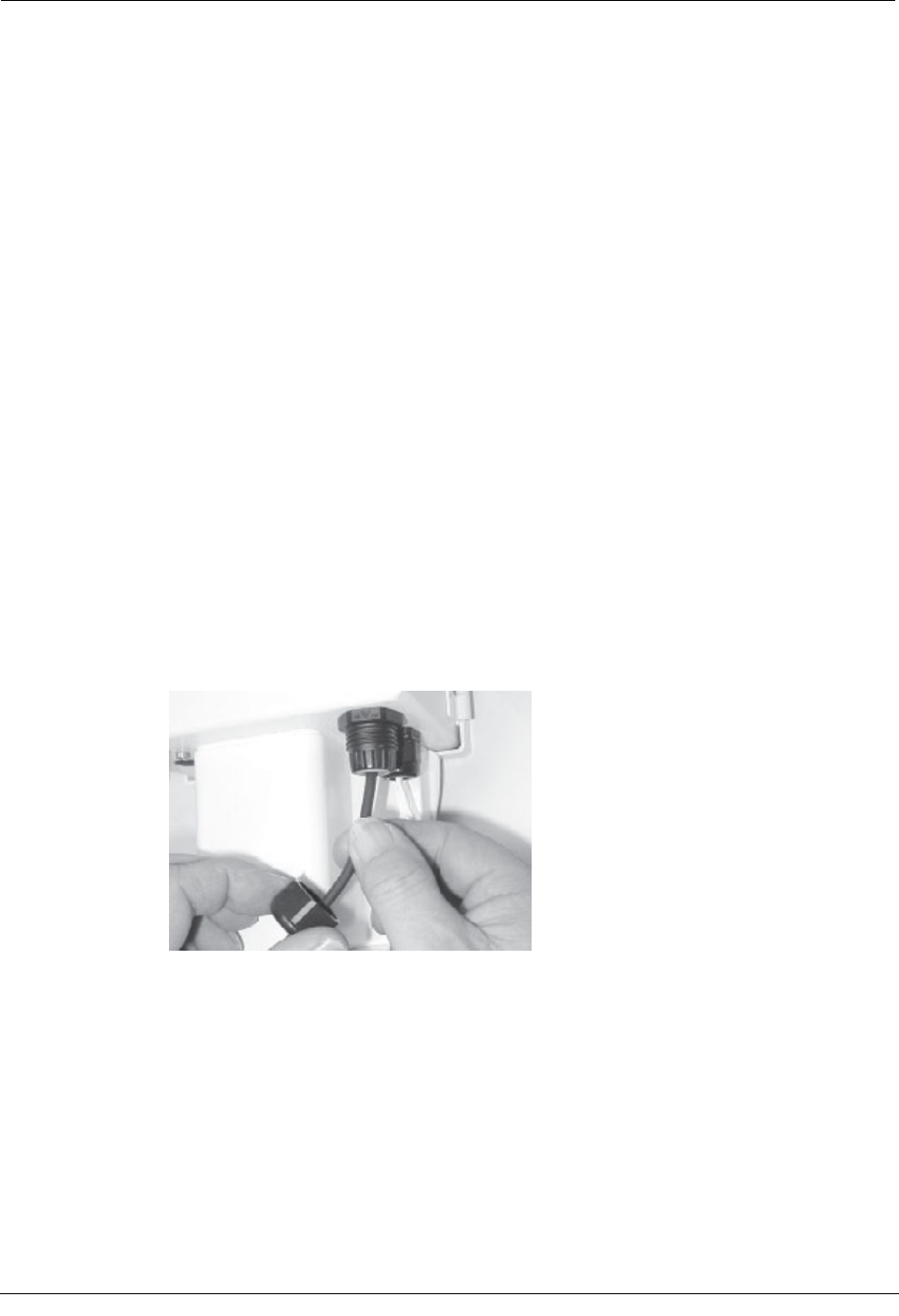
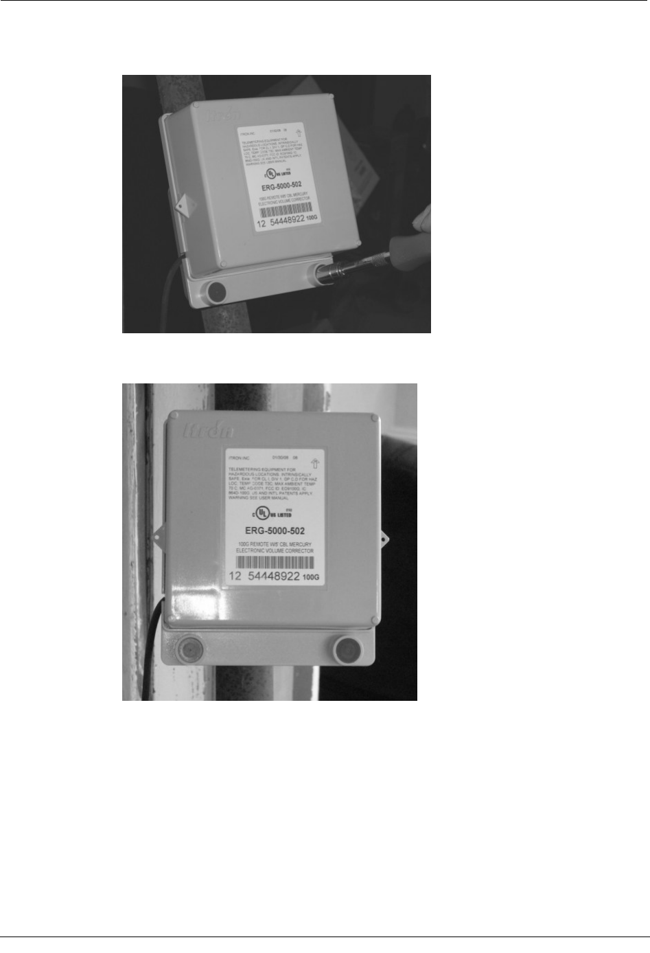
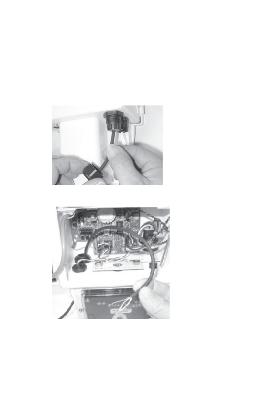
To connect the ERT cable to the corrector
1. Insert the ERT cable into the compression connector.
16 Natural Gas Solutions 100G Installation Guide for Mercury Electronic Volume Correctors
DRAFT
Pipe Mounting
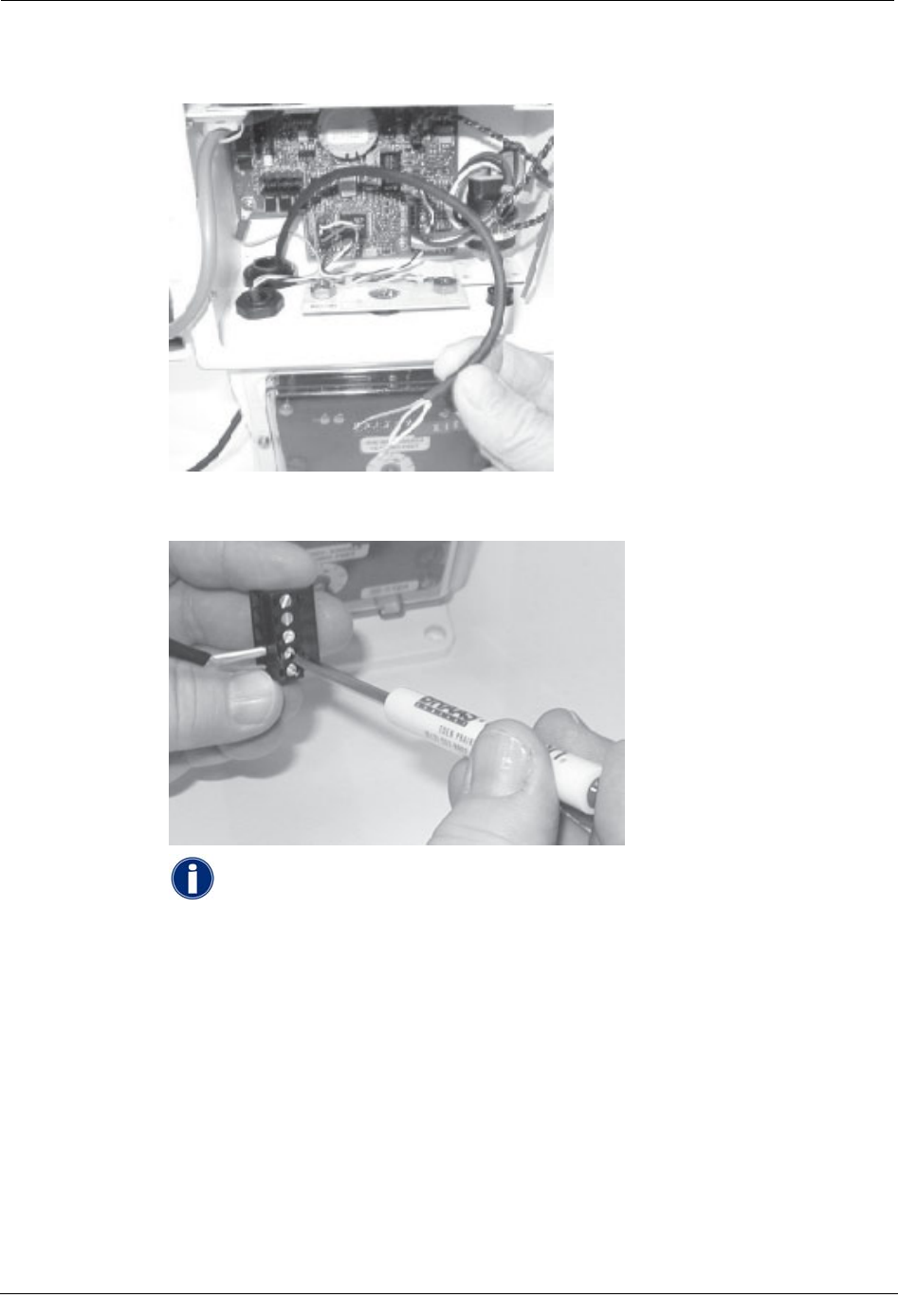
2. Strip one inch from the outer insulation and about 1/4-inch from the red,white and
blue wires. Twist the blue and white wires together.
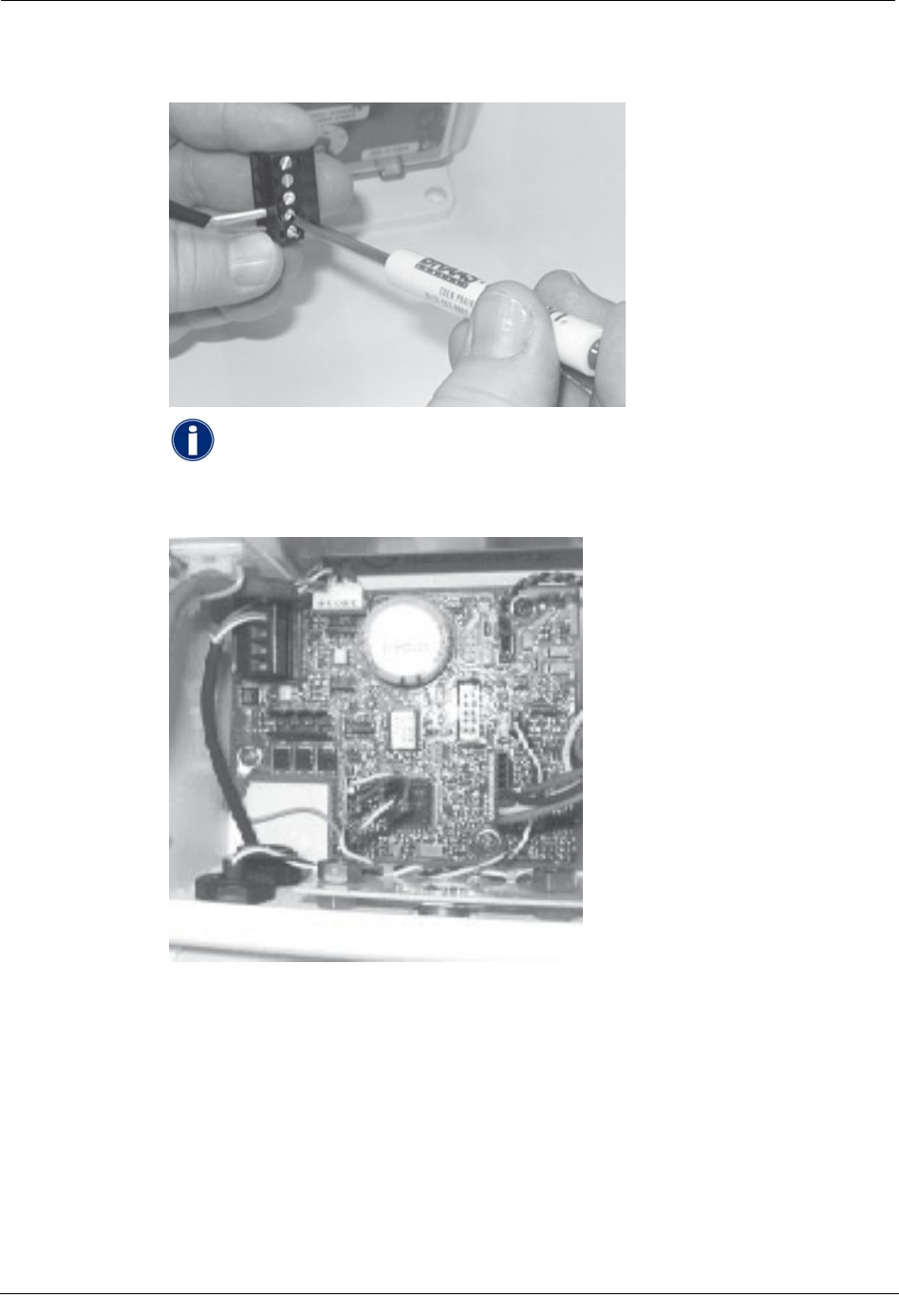
3. Install the Phoenix connector (supplied by Mercury). Connect the red, blue and white
wires to the Phoenix connector terminals as directed in Code Settings on page 3.
NOTE In EC-AT units, the connector might be soldered to the pulse board.
Natural Gas Solutions 100G Installation Guide for Mercury Electronic Volume Correctors 17
DRAFT
Chapter 2 Installing the 100G Remote ERT Module
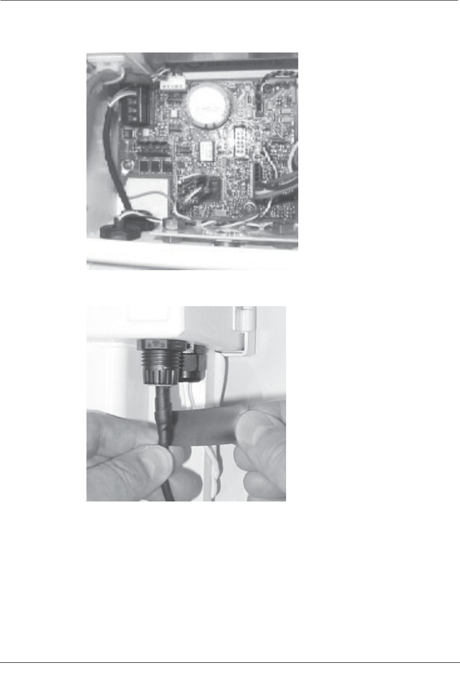
4. Install the connector so that the"K" terminal is topmost, leaving some slack in the
cable.
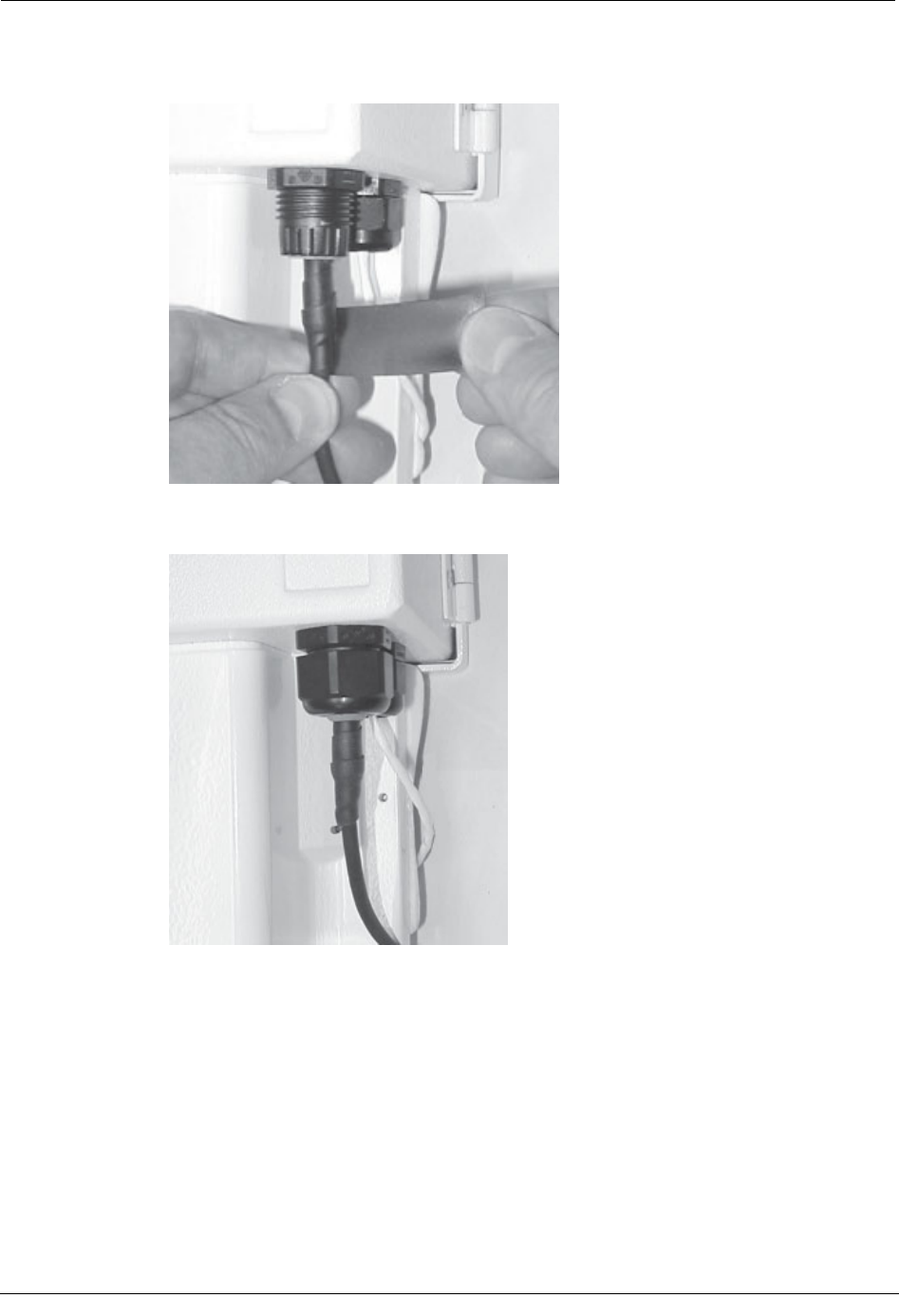
5. To hold the cable in place, wrap and stretch some rubber tape at the compression
connector.
18 Natural Gas Solutions 100G Installation Guide for Mercury Electronic Volume Correctors
DRAFT
Pipe Mounting
6. Install and tighten compression nut. This provides strain relief and seals the
connection.
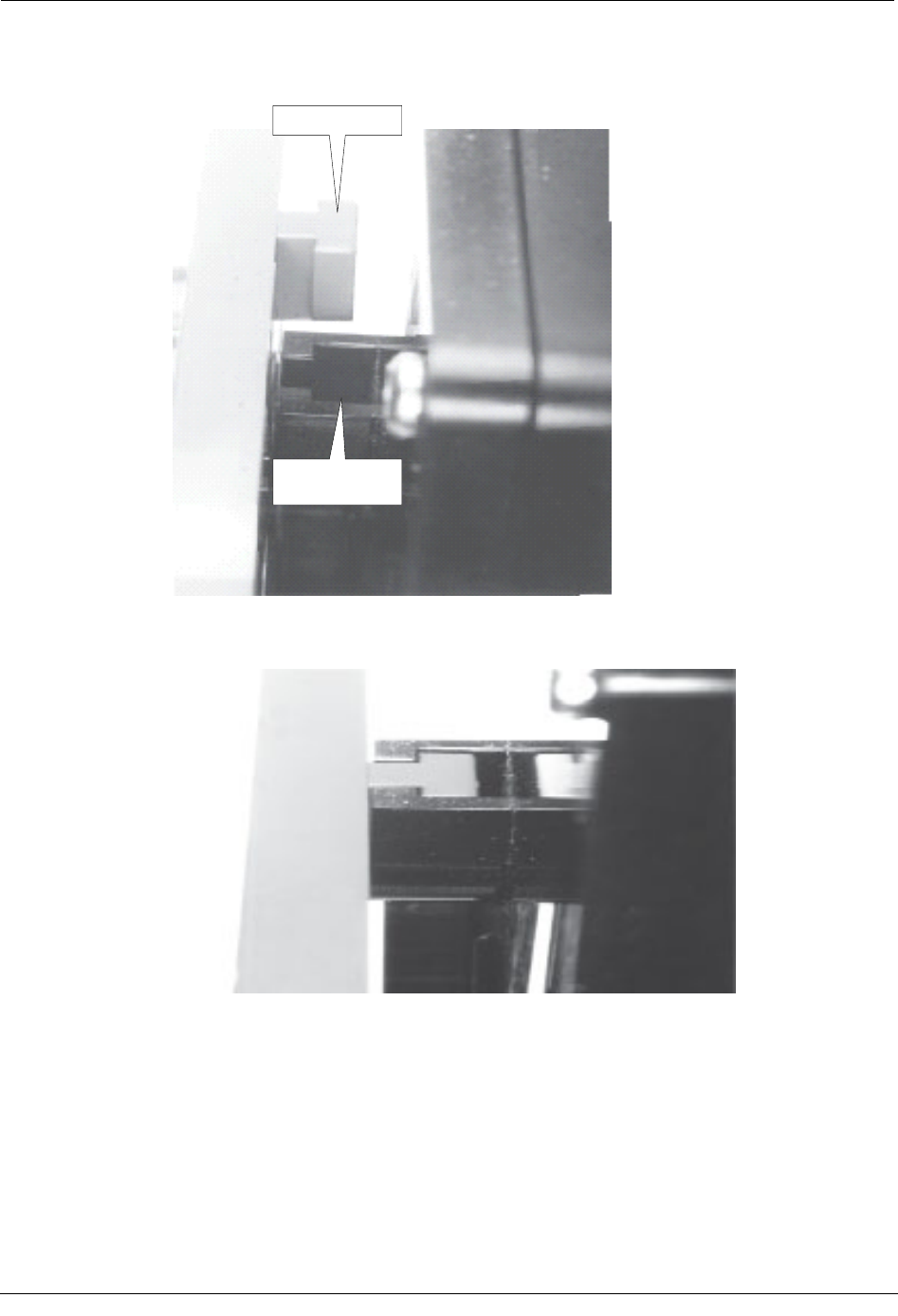
To install tamper seals and cable ties
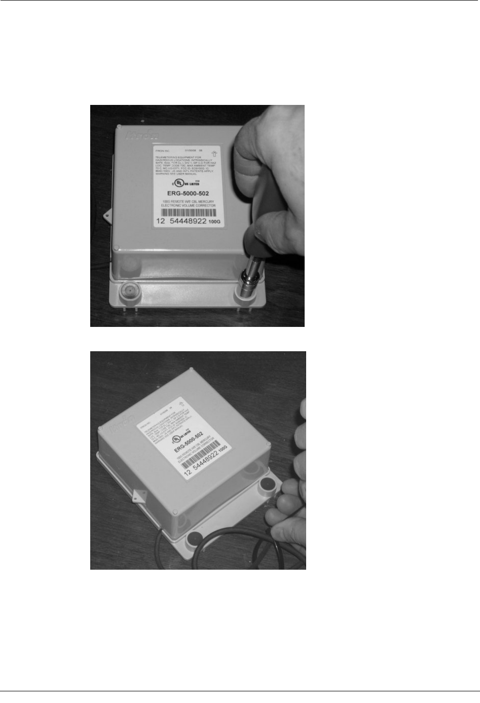
1. Get two new tamper seals from the installation Kit.
2. Place anew tamper seal over each ERT module mounting screw.
Natural Gas Solutions 100G Installation Guide for Mercury Electronic Volume Correctors 19
DRAFT
Chapter 2 Installing the 100G Remote ERT Module
3. Push both tamper seals all the way into place with a 1/4-inch nut driver or similar
tool.
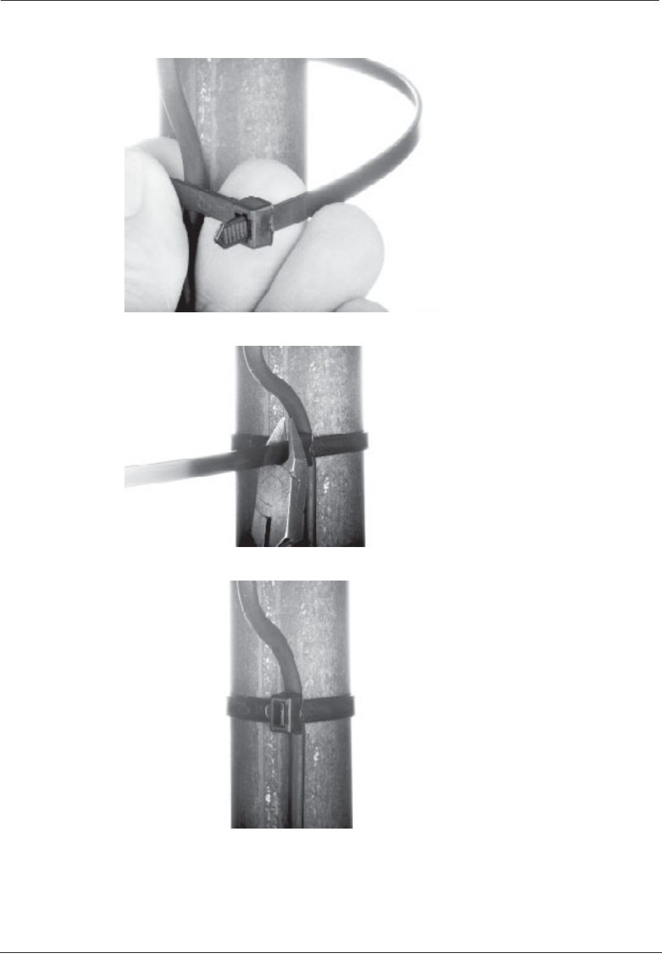
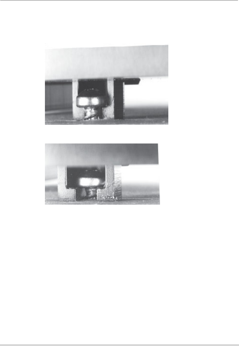
The100G Remote ERT Module should look like this after the tamper seals have been
installed.
20 Natural Gas Solutions 100G Installation Guide for Mercury Electronic Volume Correctors
DRAFT
Pipe Mounting
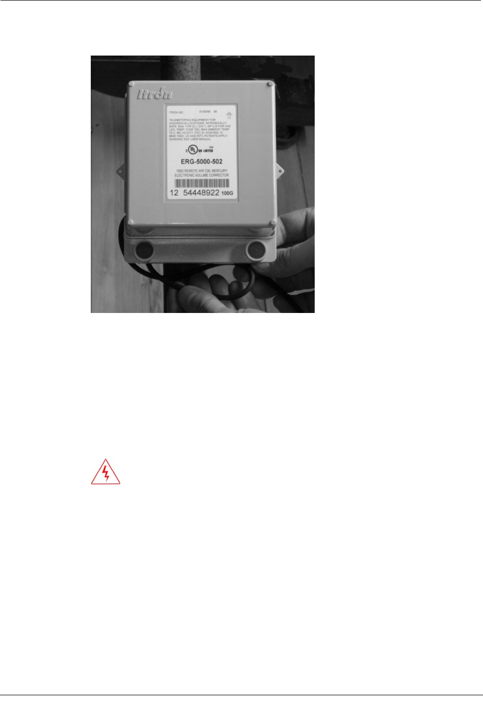
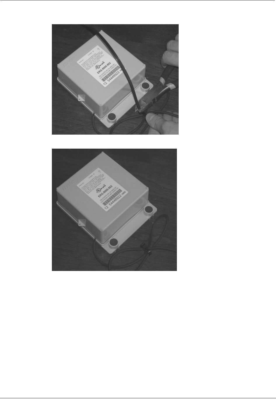
4. Loop a cable tie around the pipe and the ERT cable.
5. Pull the cable tie tight and cut off excess length. Dispose of the cut-off piece properly.
When finished, the cable tie should look like this.
Natural Gas Solutions 100G Installation Guide for Mercury Electronic Volume Correctors 21
DRAFT
Chapter 2 Installing the 100G Remote ERT Module
6. Push any excess wire up between the back of the ERT module and the face of the
adapter plate.
Flat Surface Mounting
To mount the 100G Remote ERT Module on a flat surface
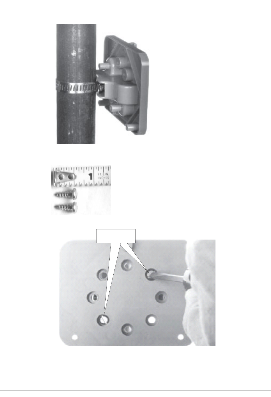
1. Drill three pilot holes in the mounting surface the proper size for the mounting screws,
as shown in the drilling template.
WARNING! Do not strike electrical wires or damage anything on the other side
of the surface you are going to mount the ERT module on when you drill the
holes and install the screws.
22 Natural Gas Solutions 100G Installation Guide for Mercury Electronic Volume Correctors
DRAFT
Flat Surface Mounting
The holes for the bottom two screws must be on a horizontal line.
If you mount the ERT module on a wood surface, use the mounting screws included
with the ERT module or screws with the same size heads.
2. Get the three 1 1/2 inch mounting screws from the installation kit.
3. Turn the top mounting screw part way into the mounting surface.
Natural Gas Solutions 100G Installation Guide for Mercury Electronic Volume Correctors 23
DRAFT
Chapter 2 Installing the 100G Remote ERT Module
4. Get an ERT module assembly.
5. Turn the screw into the mounting surface until the back side of the ERT module
mounting lug recess at the top of the ERT module will just barely slide under the
screw head.
6. Push the ERT module upward until the screw head is all the way into the screw-head
mounting recess at the top of the ERT module.
24 Natural Gas Solutions 100G Installation Guide for Mercury Electronic Volume Correctors
DRAFT
Flat Surface Mounting
7. Install and fully tighten the two bottom ERT module mounting screws.
Program the ERT
The ERT must be programmed using the FC200SR with EndPoint-Link software. See the
Endpoint-Link ERT Programming Guide (TDC-0411) for more information.
IMPORTANT You must perform the following programming procedure for
the ERT module to function properly.
When programming the ERT module, you must take note of the drive rate shown on the
index of the meter. Program the meter based on the drive rate shown on the index.
To program the ERT module
1. Using the FC200SR, program the reading of the index that was on the meter into the
ERT module assembly.
• For initial programming, hold the FC200SR approximately 1 foot away from
the 100G.
• For reprogramming (30 days or more past initial programming), hold the
FC200SR approximately 4 to 5 feet away from the 100G.
Be sure to program the 100G to the correct mode for the reading technology that will
be used (for example, Fixed Network Mode, Mobile/Handheld Mode, or Hard to Read
Mobile/Handheld Mode). In Endpoint-Link Pro v5.0, you will have access to the one
mode that was defined by your system administrator.
Natural Gas Solutions 100G Installation Guide for Mercury Electronic Volume Correctors 25
DRAFT
Chapter 2 Installing the 100G Remote ERT Module
2. Read the ERT module assembly using the FC200SR. Consult the EndPoint-Link ERT
Programming Guide (TDC-0411) or other applicable instructions for details on how to
read an ERT.
• If this reading is higher than the one you programmed in step 1 above, the ERT
module assembly is counting correctly.
• If the ERT module assembly reading is not higher than what was programmed
in step 1, replace the ERT module with a new one.
To connect the ERT cable to the corrector
1. Insert the ERT cable into the compression connector.
2. Strip one inch from the outer insulation and about 1/4-inch from the red,white and
blue wires. Twist the blue and white wires together.
26 Natural Gas Solutions 100G Installation Guide for Mercury Electronic Volume Correctors
DRAFT
Flat Surface Mounting
3. Install the Phoenix connector (supplied by Mercury). Connect the red, blue and white
wires to the Phoenix connector terminals as directed in Code Settings on page 3.
NOTE In EC-AT units, the connector might be soldered to the pulse board.
4. Install the connector so that the"K" terminal is topmost, leaving some slack in the
cable.
Natural Gas Solutions 100G Installation Guide for Mercury Electronic Volume Correctors 27
DRAFT
Chapter 2 Installing the 100G Remote ERT Module
5. To hold the cable in place, wrap and stretch some rubber tape at the compression
connector.
6. Install and tighten compression nut. This provides strain relief and seals the
connection.
28 Natural Gas Solutions 100G Installation Guide for Mercury Electronic Volume Correctors
DRAFT
Flat Surface Mounting
To install tamper seals and cable ties
1. Get two new tamper seals from the installation kit.
2. Place a new tamper seal over each ERT module mounting screw and push both seals
all the way into place with a 1/4-inch nut driver or similar tool.
3. Secure extra cable with a cable tie.
Natural Gas Solutions 100G Installation Guide for Mercury Electronic Volume Correctors 29
DRAFT
Chapter 2 Installing the 100G Remote ERT Module
4. Pull the cable tie tight and cut off excess length. Dispose of the cut-off piece properly.
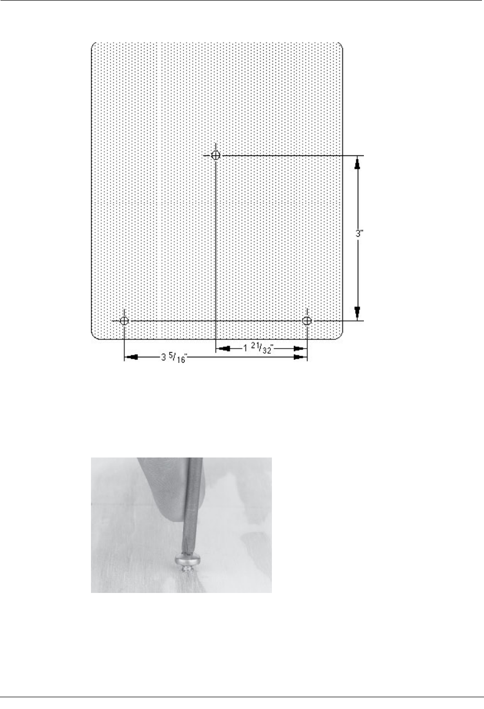
When finished, the tamper seals and cable should look like this.
Functional Specifications
Power source: Lithium battery
Radio programming parameters: LCD reading, number of digits, count rate, security
level
Mercury corrector programming parameters:
• Correctors must have Form A board. Form C is NOT supported.
• Item # 056: Pulse A Scaling. Set at 2.0000 for a form A switch.
• Item #057: Pulse A Scaling. Set at 2.0000 for a form A switch.
• Item #058: Pulse A Scaling. Set at 2.0000 for a form A switch.
30 Natural Gas Solutions 100G Installation Guide for Mercury Electronic Volume Correctors
DRAFT

Physical Specifications
• Item # 093: Type of gas volume information to be sent. For CorVol selected, must be
set at 0.
• Item # 094: Type of gas volume information to be sent. For CorVol selected, must be
set at 0.
• Item # 095: Type of gas volume information to be sent. For CorVol selected, must be
set at 0
• Item # 096: Corrected Volume Display: Must be set at 1, 2, 3 or 4 blanks. ERT does
not support a setting of 0 blanks.
• Item # 115: Output Pulse Code: Must be set at 1 or 2.
Operating temperatures: –40°F to + 158°F (–40°C to +70°C)
Operating humidity: 5 to 95 percent non-condensing relative humidity
Product identification: Numeric and bar-coded ERT module type and serial number
FCC compliance: Part 15 certified
Intrinsically safe per: Factory Mutual and UL Class 1, Division 1, Groups C and D
Physical Specifications
Materials of construction: Black polycarbonate housing; encapsulated electronics
Operational Specifications
Receive frequency: 952 and 956 MHz (MAS Bands)
Transmit frequency: 910 to 920 MHz
Data integrity: Verified in every data message
Natural Gas Solutions 100G Installation Guide for Mercury Electronic Volume Correctors 31
DRAFT

Chapter 2 Installing the 100G Remote ERT Module
32 Natural Gas Solutions 100G Installation Guide for Mercury Electronic Volume Correctors
DRAFT