Itron 100TCP AMR transceiver device for utility distribution systems User Manual
Itron Inc AMR transceiver device for utility distribution systems Users Manual
Itron >
Users Manual

100T-CP Cathodic Protection Telemetry Module
Installation Guide
TDC-1344-000
Identification
100T-Cathodic Protection (CP) Telemetry Module Installation Guide
04December 2012 TDC-1344-000
100T-CP cathodic protection telemetry module TEL-1000-003
Copyright
© 2012 Itron, Inc. All rights reserved.
Confidentiality Notice
The information contained herein is proprietary and confidential and is provided subject to the condition that (i) it is held in confidence except to the extent required otherwise by law and (ii) it is
used only for the purposes described herein. Any third party given access to this information is similarly bound in writing.
Trademark Notice
Itron is a registered trademark of Itron, Inc.
All other product names and logos in this documentation are used for identification purposes only and may be trademarks or registered trademarks of their respective companies.
Compliance Statement
This device complies with Part 15 of the FCC Rules. These limits are designed to provide reasonable protection against harmful interference in a residential installation. Operation is subject to
the following two conditions:
• This device may not cause harmful interference.
• This device must accept any interference that may cause undesirable operation.
This device must be permanently mounted such that it retains a distance of 20 centimeters (7.9 inches) from all persons in order to comply with FCC RF exposure levels.
This equipment has been tested and found to comply with the limits for a Class B digital device, pursuant to Part 15 of the FCC Rules. These limits are designed to provide reasonable
protection against harmful interference in a residential installation. This equipment generates, uses, and can radiate radio frequency energy and, if not installed and used in accordance with the
instructions, may cause harmful interference to radio communications. However, there is no guarantee that interference will not occur in a particular installation.
• If this equipment does cause harmful interference to radio or television reception, which can be determined by turning the equipment off and on, the user is encouraged to try to
correct the interference by one or more of the following measures:
• Reorient or relocate the receiving antenna.
• Increase the separation between the equipment and receiver.
• Connect the equipment into an outlet on a circuit different from that to which the receiver is connected.
• Consult the dealer or an experienced radio or TV technician for help.
Compliance Statement
This equipment complies with policies RSS-210 and RSS-GEN of the Industry
Canada rules.
Operation is subject to the following two conditions:
(1) this device may not cause interference, and
(2) this device must accept any interference, including interference that may cause
undesired operation of the device.
Déclaration de conformité
Le présent appareil est conforme aux CNR d'Industrie Canada applicables aux appareils radio exempts de licence.
L'exploitation est autorisée aux deux conditions suivantes :
(1) l'appareil ne doit pas produire de brouillage, et
(2) l'utilisateur de l'appareil doit accepter tout brouillage radioélectrique subi, même si le brouillage est susceptible d'en
compromettre le fonctionnement.
Transportation Classification
The Federal Aviation Administration prohibits operating transmitters and receivers on all commercial aircraft. When powered, any 100T telemetry module is considered an operating transmitter
and receiver and cannot be shipped by air. All product returns must be shipped by ground transportation.
Modifications and Repairs
To ensure system performance, this device and antenna shall not be changed or modified without the expressed approval of Itron. Any unauthorized modification will void the user's authority to
operate the equipment.
Safety Statements
Warning Category 0. Do not use measuring leads for other measuring categories.
• Normal maximum operating voltage = 30V AC.
• Maximum withstand voltage = 60V AC
• Maximum impulse voltage = 4 kV
Warning Follow these procedures to avoid injury to yourself or others:
• The lithium battery may cause a fire or chemical burn if it is not disposed of properly.
• Do not recharge, disassemble, heat above 100º Celsius (212º Fahrenheit), crush,
expose to water, or incinerate the lithium battery.
• Keep the lithium battery away from children.
• Fire, explosion, and severe burn hazard.
Warning Only authorized and qualified personnel should attempt to install Itron equipment. Attempts to
do so by others might void any maintenance contract with your company. Unauthorized service
personnel might be subject to shock hazard on some Itron equipment if removal of protective covers is
attempted.
Warning To prevent ignition of flammable or combustible atmospheres, disconnect power before
servicing.
Warning Substitution of components may impair intrinsic safety.
Warning These devices are not field-repairable. Before installation or removal, measure the terminal
voltages of the test station to ensure the voltage is below 30V AC.
Suggestions
If you have comments or suggestions on how we may improve this documentation, send them to TechnicalCommunicationsManager@itron.com
If you have questions or comments about the software or hardware product, contact Itron Technical Support:
Contact
• Internet: www.itron.com
• E-mail: support@itron.com
• Phone: 1 877 487 6602

TDC
-1344-000 100T-CP Cathodic Protection Telemetry Module Installation Guide v
Proprietary and Confidential
Before You Begin ......................................................................................................... vi
Document Purpose ............................................................................................................................. vi
Chapter 1 100T-CP Cathodic Protection Telemetry Module Overview..................... 1
100T-CP Security ................................................................................................................................ 1
Configuration and Programming ......................................................................................................... 1
100T-CP Telemetry Module Specifications ......................................................................................... 2
Related Documents .................................................................................................................. 2
Installation Prerequisites ..................................................................................................................... 3
Chapter 2 Mounting the 100T-CP Module on the Test Station Post ......................... 4
Mounting Screw Specifications ........................................................................................................... 4
Mounting Installation Considerations .................................................................................................. 4
Mounting the 100T-CP Module on the Test Station Pipe .................................................................... 5
Chapter 3 Connecting the 100T-CP Module to the Test Station ............................. 10
Buried Reference Cell Installation ..................................................................................................... 10
Programming the 100T-CP ............................................................................................................... 12
Contents

Before You Begin
TDC
-1344-000 100T-CP Cathodic Protection Telemetry Module Installation Guide vi
Proprietary and Confidential
This installation guide observes the following documentation conventions.
Caution A Caution warns the user that failure to follow the information could
result in loss of data. Carefully read a Caution note and follow the advice or
instructions.
Warning A Warning alerts you about potential physical harm to the user or
hardware. It is important that you pay careful attention to Warning notes; read
the information, and follow the advice or instructions.
Tip A Tip provides extra hints to make a task easier to perform or a concept
easier to understand.
Note A Note supplies generic information to the user. The user could ignore the
information and continue a task without suffering any adverse consequences.
Document Purpose
This installation guide provides instructions for installing the 100T-CP cathodic protection telemetry module.
Before You Begin

TDC
-1344-000 100T-CP Cathodic Protection Telemetry Module Installation Guide 1
Proprietary and Confidential
A cathodic protection system protects buried ferrous metal pipelines from corrosion. Cathodic protection
works by making a buried metal object slightly more cathodic (or negative electrically) when compared to the
surrounding soil causing the metal object to give up electrons, not ions, to the soil. A loss of ions occurs when
metal corrodes (rusts). Pipeline companies are required, by law, to maintain cathodic protection on their
pipelines, to monitor the pipe to soil voltage and keep records of the level of protection. Pipe to soil
measurements are traditionally taken manually once a year.
The 100T-CP cathodic protection telemetry module, coupled with a buried reference cell, takes voltage
measurements to monitor the status of the cathodic protection system. 100T-CP readings are collected daily
through a fixed network system, or on a periodic basis using a mobile/handheld system to detect trends and
allow the pipeline operator to correct problems in a timely manner, satisfying regulatory protection
requirements. The 100T-CP telemetry module was developed in cooperation with the Gas Technology
Institute.
100T-CP telemetry modules operate in two distinct modes which are mutually exclusive but similar to other
100S devices. It is possible to transition between mobile and fixed network modes using a command.
• Fixed Network Mode. In fixed network mode, the telemetry module transmits monitoring information
over a ChoiceConnect Fixed Network system.
• Mobile/Handheld Mode. In mobile/handheld mode, monitoring information and parameter changes are
completed using ChoiceConnect handheld and mobile products.
100T-CP Security
The 100T-CP helps utilities authenticate and verify that status readings are delivered from a recognized CP
module. As a component of the Itron 100S solution, the 100T-CP module supports the enhanced security
model in the Itron ChoiceConnect solution for both reading and programming. If the 100T-CP modules are
shipped without enhanced security enabled, the utility can inject security key sets into the 100T-CPs at a later
date.
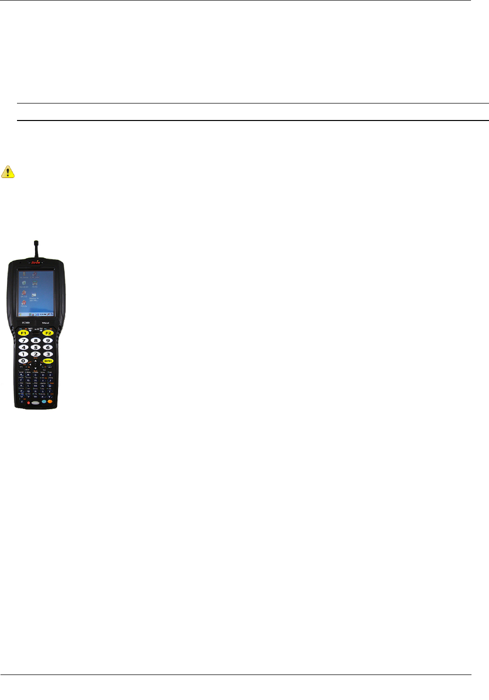
Configuration and Programming
A FC300 handheld computer loaded with Field Deployment Manager (FDM) Endpoint Tools is required to
install and configure the 100T-CP telemetry module. See the Field Deployment Manager Endpoint Tools
Mobile Application Guide (TDC-0934) for configuration and programming information.
CHAPTER 1
100T
-CP Cathodic Protection Telemetry Module Overview

100T-CP Cathodic Protection Telemetry Module Overview
TDC
-1344-000 100T-CP Cathodic Protection Telemetry Module Installation Guide 2
Proprietary and Confidential
100T-CP Telemetry Module Specifications
Functional Specifications
Description
Power source
Two "A" cell lithium batteries
Tamper detection
Tilt tamper and magnetic tamper
FCC compliance
Part 15 certified
Industry Canada compliance RSS-210 certified
Intrinsic safety classification
UL Listed Measurement Equipment
Product identification
Numeric and bar coded module type and serial number
Construction materials Gray polycarbonate housing and back plate with encapsulated
electronics
Operational Specifications
Description
Operating temperatures
-40° to 158° F (-40° to +70° C)
Operating humidity 5 to 95 percent relative humidity
Program frequency 908 MHz
Transmit frequency
Spread spectrum 908 to 924 MHz ISM band
Data integrity
Verified in every data message
Related Documents
Document Title
Document Part Number
Gas and Telemetry Module Meter Compatibility List PUB-0117-002
Gas and Telemetry Module Ordering Guide PUB-0117-001
100T-CP Cathodic Protection Telemetry Module Specification Sheet Publication
Field Deployment Manager Endpoint Tools Mobile Application Guide TDC-0934-XXX*
Field Deployment Manager Field Representative's Guide TDC-0936-XXX*
100 Series Modules and CENTRON Bridge Meter Tamper Reference Guide TDC-1028-XXX*
*The last three digits of the user and installation guides represent the document's revision level. The revision
level is subject to change without notice.

100T-CP Cathodic Protection Telemetry Module Overview
TDC
-1344-000 100T-CP Cathodic Protection Telemetry Module Installation Guide 3
Proprietary and Confidential
Installation Prerequisites
The following tools are required to install, program, and check the 100T-CP module. Specific tools may be
required for some installation locations.
• Medium flat-blade screwdriver
• Medium Phillips screwdriver
• Hand pliers
• Side-cutting pliers
• Nut driver with sockets
• Adjustable wrench
• 3M Scotchlock E-9Y crimping tool, 3M Scotchlock E-9C cartridge tool, or similar crimping tool
• All-weather electrical tape
• Voltmeter
• Itron programming device to program and check 100T-CP module installation and operation.
Note See the FDM programming guide or specification sheet for correct software version Related
Documents on page 2.
TDC
-1344-000 100T-CP Cathodic Protection Telemetry Module Installation Guide 4
Proprietary and Confidential
This chapter provides the instructions to mount the 100T-CP on the test station post (riser pipe).
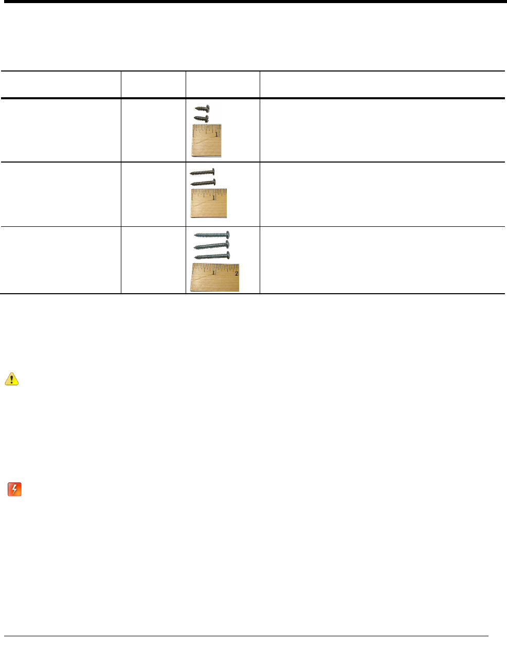
Mounting Screw Specifications
Application Itron Part
Number
Description
To mount adapter plates on the
pipe mounting bracket
SCR-0215-002
8-16 x 1/2-inch length, type 8 slotted pan-head/Phillips tapping
screw, corrosion-resistant steel
To mount 100T-CP modules
on the adapter plate
SCR-0215-001
8-16 x 1-inch type 8, slotted pan-head/Phillips tapping screw,
corrosion-resistant steel
To mount the 100T-CP
modules on a wall or flat
vertical surface
SCR-0009-001
10-16 x 1/2-inch type AB thread for sheet metal, Phillips
pan-head tapping screw, corrosion-resistant steel
Mounting Installation Considerations
Mount the 100T-CP in a vertical position on the test station pipe with the telemetry module label directional
arrow pointed upward.
Caution Upright vertical positioning is very important because:
• 100T-CP cathodic protection telemetry modules are designed with the antenna in a
vertical direction so the antenna is parallel to the reading device (which has a vertical
antenna). Matching antenna polarity can greatly affect RF performance and enable
easy module reading.
• 100T-CP cathodic protection telemetry modules are designed so the tilt tamper is
vertical. It is important to maintain vertical positioning in the field to enable tilt tamper
stability.
Warning Do not mount the 100T-CP in an orientation other than vertical (module label arrow
pointed upward). Violating the mounting orientation requirements will void the product
warranty.
Test for induced AC voltage on pipeline (using an accepted test procedure) prior to installing
the 100T-CP module.
CHAPTER 2
Mounting the 100T
-CP Module on the Test Station Post
Mounting the 100T-CP Module on the Test Station Post
TDC
-1344-000 100T-CP Cathodic Protection Telemetry Module Installation Guide 5
Proprietary and Confidential
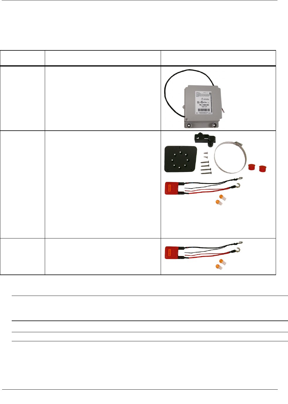
Mounting the 100T-CP Module on the Test Station Pipe
The following items are required to mount the 100T-CP on the test station pipe:
Itron Part
Number
Description
TEL-1000-003 100T-CP cathodic protection telemetry module
CFG-5006-701 100T-CP Hardware Installation Kit
Kit includes:
(1) one band clamp
(2) two tamper seals
pipe bracket
adapter plate
lightning suppressor kit (also includes 2 gel-
connectors)
Screws:
(2) 1/2-inch, to attach the adapter plate to pipe bracket
(2) 1-inch, to attach the telemetry module to the
adapter plate
(3) 1 1/2-inch, to attach the telemetry module to a
vertical surface (wall)
CFG-5006-710
(may be ordered
with 100T-CP
Harware Kit or
separately)
Lightning Suppressor Kit
Kit includes:
Lightning suppressor
(2) gel connectors
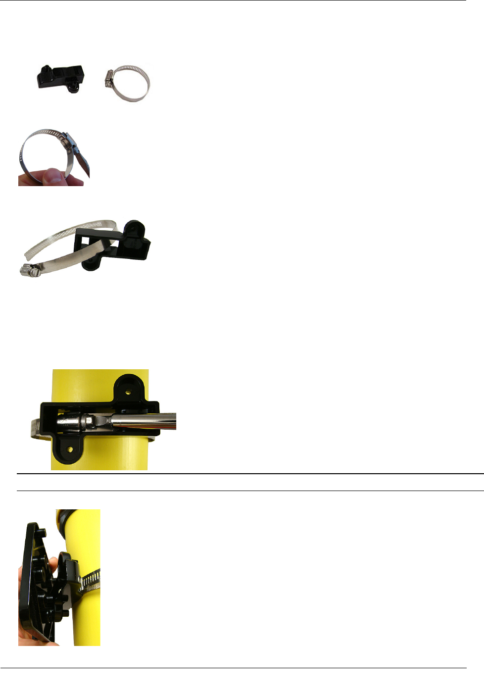
To mount the pipe bracket on a vertical pipe
Warning A vertical mounting position is important to maximize RF performance. Mount the 100T-CP
with the module's label arrow pointing up. The module's arrow must never point to either side or upside
down. The module's tilt tamper functionality is designed to operate with the module installed vertically.
1. Drill a 3/16" hole for the 100T-CP cable in the riser post 1-1/2" below the test station base.
Caution Protect wires within riser post from damage when the hole is drilled.
Mounting the 100T-CP Module on the Test Station Post
TDC
-1344-000 100T-CP Cathodic Protection Telemetry Module Installation Guide 6
Proprietary and Confidential
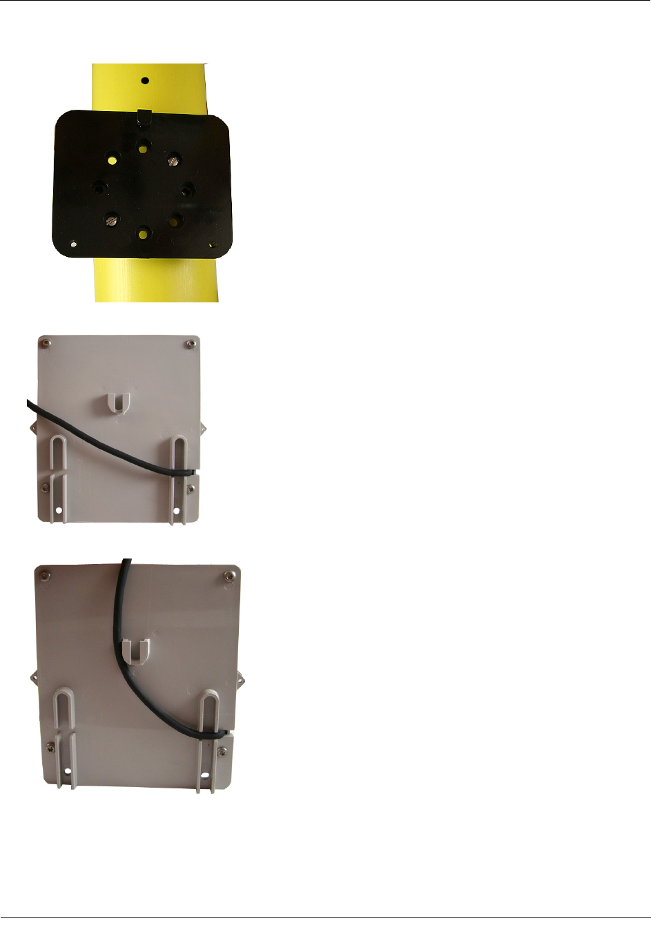
2. Remove the pipe bracket and band clamp from the hardware kit (Itron part number CFG-5006-701).
3. Loosen the band clamp screw until the end of the band releases.
4. Push the end of the clamp's band through the holes in the pipe bracket. Itron suggests orienting the pipe
bracket as shown below.
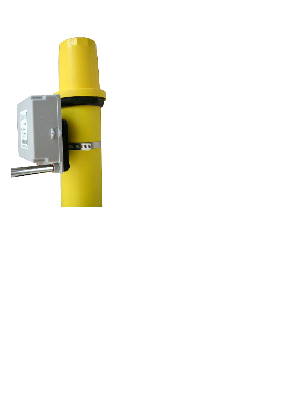
5. Place the band clamp around the riser pipe approximately 3-1/2" below the test station base or
approximately 2" below the previously drilled hole. The band will loosely wrap around the riser post.
6. Push the end of the band through the band clamp screw assembly. Turn the band clamp's screw assembly
to fit into the pipe bracket opening.
7. Tighten the clamp screw (using a flat bladed screwdriver or 5/16" nut driver) until the band clamp is
secure on the pipe.
Caution The pipe bracket must fit firmly against the riser post to prevent slippage.
8. Align the mounting plate screw holes to the pipe bracket adapter plate screw holes.
Mounting the 100T-CP Module on the Test Station Post
TDC
-1344-000 100T-CP Cathodic Protection Telemetry Module Installation Guide 7
Proprietary and Confidential
9. Insert the adapter plate mounting screws. Tighten the screws in an alternating pattern.
10. Route the 100T-CP cable through the channel in the standoff on the backplate.
11. Route the cable on the left of the mounting post slot.
Mounting the 100T-CP Module on the Test Station Post
TDC
-1344-000 100T-CP Cathodic Protection Telemetry Module Installation Guide 8
Proprietary and Confidential
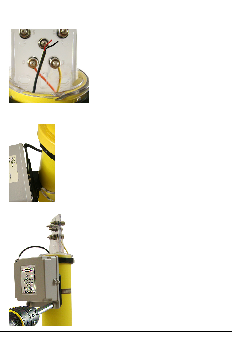
12. Thread the 100T-CP cable through the hole previously drilled in the riser post and gently pull the cable
through the top of the riser post.
13. Slide the 100T-CP module mounting post slot onto the mounting post on the adapter plate. Align the
100T-CP mounting screw holes with those on the adapter plate. Verify the cable is on the left side of the
mounting post slot.
14. Insert the mounting screws and tighten in an alternating pattern.
Mounting the 100T-CP Module on the Test Station Post
TDC
-1344-000 100T-CP Cathodic Protection Telemetry Module Installation Guide 9
Proprietary and Confidential
15. Install the tamper seals in the screw mounting cups. A tamper seal is correctly seated when it is recessed
1/16" into the cup.
TDC
-1344-000 100T-CP Cathodic Protection Telemetry Module Installation Guide 10
Proprietary and Confidential
This section provides the instructions to connect the 100T-CP to the cathodic protection test station.
Buried Reference Cell Installation
The 100T-CP must be connected to a Cu-CuSO4 reference cell designed for burial to measure pipe to soil
voltage. The reference cell must be purchased from a third-party vendor and installed according to the
manufacturer's specifications.
To connect the 100T-CP to the lightning suppressor and buried reference cell
1. Confirm test station integrity by using a voltmeter to read the pipe to soil voltage at the structure and
reference cell terminals on the test station terminal board.
2. Connect the lightning suppressor hook terminals to the test station terminal posts following the table
below and tighten the connections. Insert the lightning suppressor down into the riser post.
Note The lightning suppressor (CFG-5006-710) will not fit into a <1" riser post.
Lightning Suppressor Connection Table
Red lightning suppressor wire Test lead(s) connected to pipe
Black lightning suppressor wire To test lead from buried reference cell
CHAPTER 3
Connecting the 100T
-CP Module to the Test Station
Connecting the 100T-CP Module to the Test Station
TDC
-1344-000 100T-CP Cathodic Protection Telemetry Module Installation Guide 11
Proprietary and Confidential
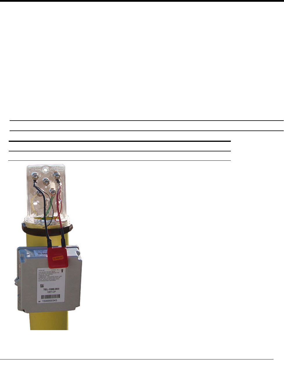
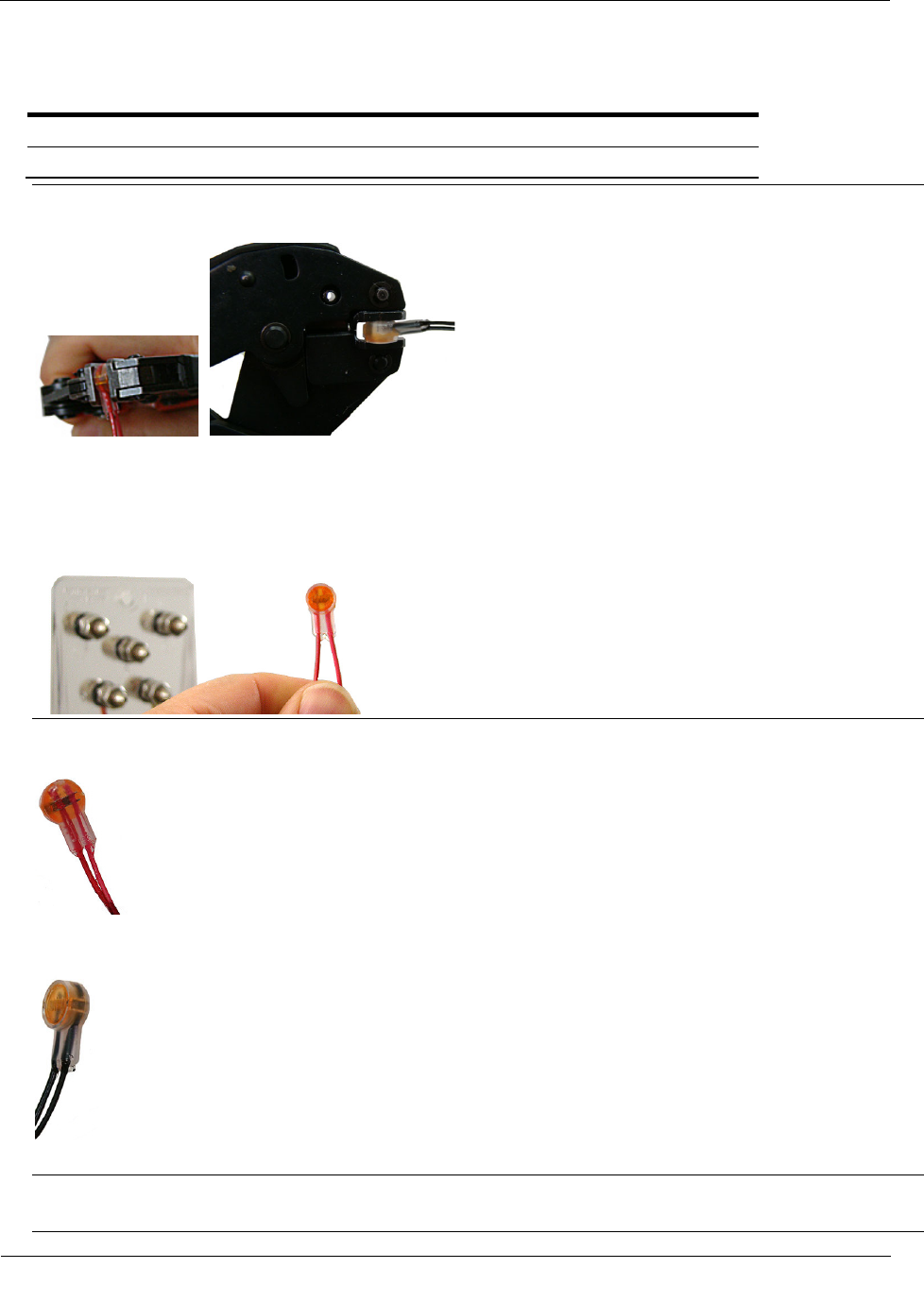
3. Connect the 100T-CP lead wires to the lightning suppressor following the table indications.
Lightning Suppressor to 100T-CP Connection Table
Red lightning suppressor wire Red 100T-CP wire
Black lightning suppressor wire Black 100T-CP wire
Important Use an Itron-approved crimping tool to install gel connectors. Do not use a standard pliers.
The crimping tool provides an even-pressured crimp to ensure a secure connection between the wires.
Note Do not strip lead wire prior to inserting the wire into the gel connector.
Warning Crimping the connector forces some sealant out of the connector. The sealant protects the
inside of the connector against insects, moisture, and other contaminants. The sealant may cause minor
eye and skin irritation. Avoid eye contact. Avoid prolonged or repeated skin contact. Contact Itron
Support for Material Safety Data Sheets (MSDS).
4. Insert the red wire from the lightning suppressor and the red wire from the 100T-CP into a gel connector.
Crimp the connector.
5. Insert the black wire from the lightning suppressor and the black wire from the 100T-CP into the
remaining gel connector. Crimp the connector.
6. Insert the excess module cable down into the riser post.
Warning Allow six minutes for the 100T-CP to stabilize with the system before you check voltage level
and polarity.
Connecting the 100T-CP Module to the Test Station
TDC
-1344-000 100T-CP Cathodic Protection Telemetry Module Installation Guide 12
Proprietary and Confidential
7. Perform a Check Endpoint using a handheld computer and FDM to display the pipe to soil and AC
voltage readings measured by the 100T-CP.
8. A negative DC voltage indicates a successful connection. If the Check Endpoint indicates a positive DC
voltage, switch the red and black lightning suppressor leads on the test station terminals.
9. Perform a Check Endpoint to verify a negative DC voltage.
Warning Allow one minute between readings for the voltage to stabilize.
Programming the 100T-CP
Caution You must program the 100T-CP before use.
Program the 100T-CP using an FC200SR or FC300 handheld computer loaded with FDM Endpoint Tools.
For complete programming information, see the Field Deployment Manager Endpoint Tools Mobile
Application Guide (TDC-0934).
Program the Utility ID into the 100T-CP using the handheld computer. Optionally, you can program the
100T-CP to enable the enhanced security key, Test Station ID, and voltage reading Capture Hour. For all
programming and Check Endpoint operations, hold the handheld within six feet of the target telemetry
module and as close to vertical as possible. Programming parameters are based on the configuration file
loaded into the programming device.