Itron 100THON AMR transceiver device for utility gas/telemetry meters User Manual 100T HON Telemetry Module Installation Guide
Itron Inc AMR transceiver device for utility gas/telemetry meters 100T HON Telemetry Module Installation Guide
Itron >
Users Manual

Natural Gas Solutions
100T-HON Honeywell Telemetry Module
Installation Guide
TDC-1346-000

TDC-1346-000 100T-HON Honeywell Telemetry Module Installation Guide ii
Proprietary and Confidential
Identification
100T-HON Honeywell Telemetry Module Installation Guide
13 March 2013 TDC-1346-000
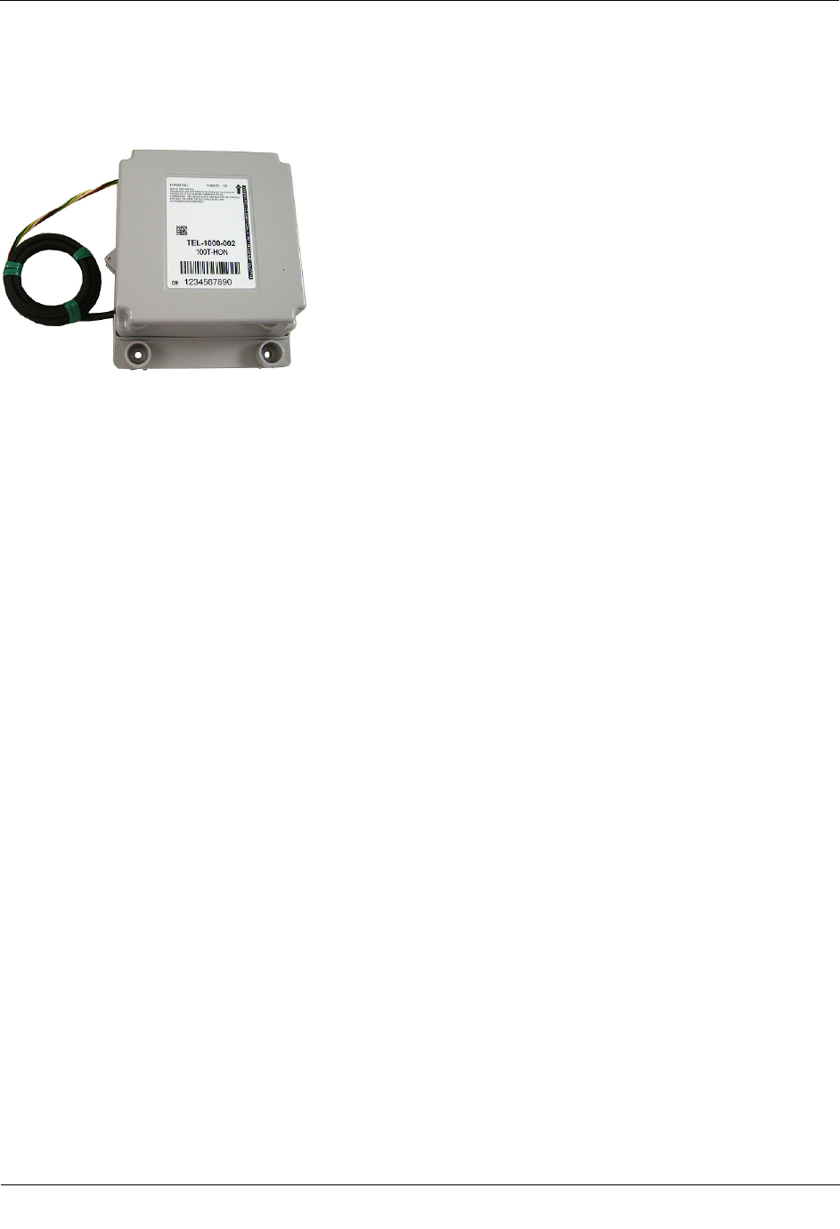
100T-HON
100-T HON part number: TEL-1000-002
Copyright
© 2013 Itron, Inc. All rights reserved.
Confidentiality Notice
The information contained herein is proprietary and confidential and is provided subject to the condition that (i) it is held in confidence except to the extent required otherwise by law and (ii) it is
used only for the purposes described herein. Any third party given access to this information is similarly bound in writing.
Trademark Notice
Itron is a registered trademark of Itron, Inc.
All other product names and logos in this documentation are used for identification purposes only and may be trademarks or registered trademarks of their respective companies.
Compliance Statement
This device complies with Part 15 of the FCC Rules. These limits are designed to provide reasonable protection against harmful interference in a residential installation. Operation is subject to
the following two conditions:
• This device may not cause harmful interference.
• This device must accept any interference that may cause undesirable operation.
This device must be permanently mounted such that it retains a distance of 20 centimeters (7.9 inches) from all persons in order to comply with FCC RF exposure levels.
This equipment has been tested and found to comply with the limits for a Class B digital device, pursuant to Part 15 of the FCC Rules. These limits are designed to provide reasonable
protection against harmful interference in a residential installation. This equipment generates, uses, and can radiate radio frequency energy and, if not installed and used in accordance with the
instructions, may cause harmful interference to radio communications. However, there is no guarantee that interference will not occur in a particular installation.
If this equipment does cause harmful interference to radio or television reception, which can be determined by turning the equipment off and on, the user is encouraged to try to correct the
interference by one or more of the following measures:
• Reorient or relocate the receiving antenna.
• Increase the separation between the equipment and receiver.
• Connect the equipment into an outlet on a circuit different from that to which the receiver is connected.
• Consult the dealer or an experienced radio or TV technician for help.
Compliance Statement
This equipment complies with policies RSS-210 and RSS-GEN of the Industry Canada
rules. Operation is subject to the following two conditions:
• (1) this device may not cause interference, and
• (2) this device must accept any interference, including interference that may
cause undesired operation of the device.
Déclaration de conformité
Le présent appareil est conforme aux CNR d'Industrie Canada applicables aux
appareils radio exempts de licence. L'exploitation est autorisée aux deux conditions
suivantes:
• (1) l'appareil ne doit pas produire de brouillage, et
• (2) l'utilisateur de l'appareil doit accepter tout brouillage radioélectrique subi,
même si le brouillage est susceptible d'en compromettre le fonctionnement.
Modifications and Repairs
To ensure system performance, this device and antenna shall not be changed or modified without the expressed approval of Itron. Any unauthorized modification will void the user’s authority to
operate the equipment.
Transportation Classification
The Federal Aviation Administration prohibits operating transmitters and receivers on all commercial aircraft. When powered, the 100T-HON is considered an operating transmitter and receiver
and cannot be shipped by air. All product returns must be shipped by ground transportation.
Safety Statements
Warning Follow these procedures to avoid injury to yourself or others:
• The lithium battery may cause a fire or chemical burn if it is not disposed of
properly.
• Do not recharge, disassemble, heat above 100º Celsius (212º Fahrenheit),
crush, expose to water, or incinerate the lithium battery. Fire, explosion,
and severe burn hazard.
• Keep the lithium battery away from children.
• Replace the lithium battery only with batteries meeting Itron specifications.
Any other battery may cause a fire or explosion.
Warning Only authorized Itron personnel should attempt repairs on Itron equipment.
Attempts to do so by others might void any maintenance contract with your company.
Unauthorized service personnel might also be subject to shock hazard on some Itron
equipment if removal of protective covers is attempted.
Warning To prevent ignition of flammable or combustible atmospheres, disconnect
power before servicing.
Warning Substitution of components may impair intrinsic safety.
Warning Potential Electrostatic Charging Hazard. Clean only with a damp cloth.

TDC-1346-000 100T-HON Honeywell Telemetry Module Installation Guide iii
Proprietary and Confidential
Suggestions
If you have comments or suggestions on how we may improve this documentation, send them to TechnicalCommunicationsManager@itron.com
If you have questions or comments about the software or hardware product, contact Itron Technical Support:
Contact
• Internet: www.itron.com
• E-mail: support@itron.com
• Phone: 1 877 487 6602

TDC-1346-000 100T-HON Honeywell Telemetry Module Installation Guide iv
Proprietary and Confidential

TDC
-1346-000 100T-HON Honeywell Telemetry Module Installation Guide v
Proprietary and Confidential
Before You Begin ......................................................................................................... vi
Document Purpose ............................................................................................................................. vi
Document Conventions ...................................................................................................................... vi
Chapter 1 About the 100T-HON Honeywell Telemetry Module .................................. 1
Mercury Devices Supported by the 100T-HON................................................................................... 1
Transmission Modes ........................................................................................................................... 2
100T-HON Telemetry Module Messaging ........................................................................................... 2
Itron Security Manager ........................................................................................................................ 3
Operating Modes ................................................................................................................................. 3
Specifications ...................................................................................................................................... 5
Related Documents ............................................................................................................................. 6
Installation Prerequisites ..................................................................................................................... 6
Chapter 2 Mounting the 100T-HON Telemetry Module ............................................... 8
Installation Options .............................................................................................................................. 8
Mounting Screw Specifications ........................................................................................................... 8
Mounting Installation Considerations .................................................................................................. 9
Mounting the 100T-HON Telemetry Module on a Pipe............................................................. 9
Mounting the 100T-HON Telemetry Module on a Wall or Other Flat Vertical Surface ........... 12
Chapter 3 Connecting and Configuring the Module and Instrument ...................... 15
Installation Overview ......................................................................................................................... 15
Programming the Mercury Instrument Parameters ........................................................................... 15
Honeywell Instrument Call-In Configuration ...................................................................................... 16
Connecting the 100T-HON Telemetry Module to the Instrument ...................................................... 17
The Mechanical Uncorrected Volume Switch ......................................................................... 18
Electronic Corrected Pulse Output ............................................................................... 18
Electronic Uncorrected Pulse Output ........................................................................... 18
Alarm Switch ................................................................................................................. 18
Honeywell Instrument Cable Connections .............................................................................. 18
Chapter 4 Programming the 100T-HON Telemetry Module ...................................... 26
Contents

Before You Begin
TDC
-1346-000 100T-HON Honeywell Telemetry Module Installation Guide vi
Proprietary and Confidential
Document Purpose
This installation guide provides step-by-step instructions for installing the 100T-HON telemetry module on a
Honeywell Mercury Instrument.
Document Conventions
The following documentation conventions are used in this installation guide.
Caution A Caution warns the installer that failure to follow the information in the note could
result in loss of data. Be sure to carefully read a Caution note and follow the advice or
instructions.
Warning A Warning alerts the installer about potential physical harm to the installer or
hardware. It is critical that you pay strict attention to Warning notes, read the information
carefully, and follow the advice or instructions.
Before You Begin
Tip A Tip provides the installer with extra hints or tips to make a task easier to perform or a
concept easier to understand.
Note A Note supplies generic information to the installer. The installer can ignore the
information and continue the task without suffering any adverse consequences.
TDC
-1346-000 100T-HON Honeywell Telemetry Module Installation Guide 1
Proprietary and Confidential
Itron 100T-HON telemetry modules are radio-frequency (RF) devices designed to transmit meter and
instrument data to an RF meter reading device within transmission distance of the module. The 100T-HON is
designed to interface specifically with Honeywell Mercury Instrument devices and communicates using a
protocol similar to other Itron AMR devices. The 100T-HON provides both a traditional meter reading RF
interface and a new telemetry RF interface. The 100T-HON module physically connects to the Honeywell
device.
Honeywell devices support several output mechanisms, but the majority of the information required for the
100T-HON module is collected over an RS-232 serial connection with the exception being the pulse output
representing uncorrected mechanical volumes that can be optionally added to Mini-Max, Mini-Max AT, Mini-
Max ATX, Mini-Max Rotary, and Mini-AT volume correctors.
The 100T-HON telemetry module features cut, tilt-tamper and cable-tamper reporting and security seals to
indicate physical tampering and minimize theft. Cut cable is reported when the cable is cut or disconnected
from the instrument or telemetry module. The module circuitry senses an electrical current break to report a
cut cable tamper event.
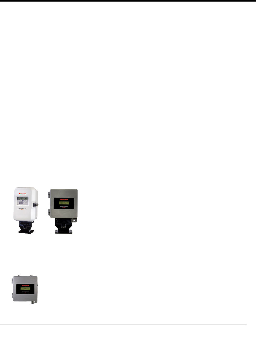
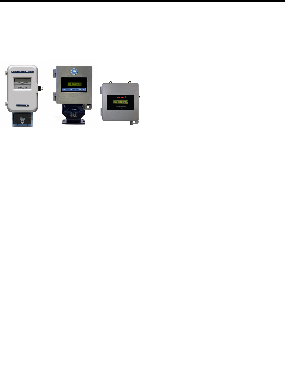
Mercury Devices Supported by the 100T-HON
The 100T-HON telemetry module supports two Mercury Instrument types:
Electronic Volume Corrector
• Mini-Max, Mini-Max AT, Mini-Max ATX and Mini-Max Rotary Correctors
• Mini-AT
Mini-AT Mini-Max
Electronic Pressure Recorder
• ERX
CHAPTER 1
About the 100T
-HON Honeywell Telemetry Module

About the 100T-HON Honeywell Telemetry Module
TDC
-1346-000 100T-HON Honeywell Telemetry Module Installation Guide 2
Proprietary and Confidential
Honeywell product features are beyond the scope of this installation guide. Please reference the Honeywell
product information for your particular Mercury Instrument.
Transmission Modes
The 100T-HON telemetry module can be set to transmit in fixed network or mobile and handheld mode.
• Fixed Network Mode. The 100T-HON telemetry module transmits a high-powered network interval
message (NIM) RF message every five minutes. Output power in this mode is 500 milliwatts or +27 dBm.
Interspersed with the high power NIM, the 100T-HON telemetry module transmits a medium power RF
message every 60 seconds at 10 milliwatts or +10 dBm; expected battery life is 20 years.
• Mobile and Handheld Mode. The 100T-HON telemetry module transmits a medium-powered RF
message (Beacon) every 15 seconds. Output power in this mode is 10 milliwatts or +10dBm; expected
battery life is 20 years.
An FCC license is not required to read 100T-HON telemetry modules.
100T-HON Telemetry Module Messaging
The 100T-HON telemetry module messaging is dependent on the transmission mode. 100T-HON telemetry
module messaging supports two bubble-up (BUP) message types and two-way commands.
• Normal BUP
• Alarm BUP. If a critical alarm is detected, the 100T-HON telemetry module enters an alarm state and
transmits the alarm details. An alarm state causes the following events:
• While the alarm window is active, any scheduled normal fixed network or mobile BUP messages are
not transmitted.
• If an acknowledgment is received, the 100T-HON telemetry module returns to its normal BUP
transmission schedule. The normal mobile and fixed network BUP messages will contain the
appropriate tamper flags set in the message.
• If an acknowledgment is not received by the 100T-HON telemetry module after the programmed
number of alarm BUP retries, the device returns to its normal BUP transmission schedule. The 100T-
HON telemetry module transmits normal mobile and fixed network BUP messages with the
appropriate alarm tamper flags set.
Alarm BUP messages contain the following information:
• Alarm ID defining the cause of the alarm
• Endpoint ID
• Utility ID
• Current extended tamper field values (ready to secure mode only)
Two-Way Commands. Fixed network and mobile command messages manage and control the status of the
100T-HON telemetry module.

About the 100T-HON Honeywell Telemetry Module
TDC
-1346-000 100T-HON Honeywell Telemetry Module Installation Guide 3
Proprietary and Confidential
Itron Security Manager
The 100T-HON telemetry module addresses two types of security, ChoiceConnect networking and 100T-
HON to Honeywell device communication, provided by Itron Security Manager.
ChoiceConnect Networking
The first model is a traditional Itron protocol that includes a complete system knowledge of the content and
purpose of each message. Security related decisions such as which key type (for example, reading or
command keys) to use when securing a message are based on the command function.
100T-HON Telemetry Module Security
The second message model is a telemetry security model. The application level message details are not known
to the ChoiceConnect system components. Messages may contain commands ranging from reading data to
those that update the state of the Honeywell device. The 100T-HON telemetry module allows 100T two-way
requests to be sent and processed through the 100T-HON telemetry module in a basic security fashion, if the
command does not change the security state of the Honeywell device.
Operating Modes
The 100T-HON telemetry module operating modes determine the module's default packet types, bubble-up
rates, and transmit power levels.
Factory Ship. Factory ship mode conserves the module battery between the time it ships from the factory
until it is deployed in the field. In factory ship mode, the module will not transmit but will periodically turn on
its receiver and listen for a command. While the module is in factory ship mode, the module will not attempt
to periodically log onto the Honeywell device to retrieve data.
Audit Mode. Audit mode reduces the read latency time so an audit can be performed on a population of
modules after installation.
Quiet Mode. Quiet mode is very similar to factory ship mode except that the module exits quiet mode
automatically after a pre-configured period of time.
Fixed Network. Fixed network mode is chosen when the device will be read by a fixed network. The 100T-
HON telemetry module behavior varies based on the connected Honeywell device.
• EVC. When the module is connected to a Honeywell EVC device, the following message types are
supported:
Bubble-up Messages:
Channel-based hourly consumption (NIM-chl)
Handheld and mobile contingency (SCM+)
Optional gas day take (GDT)
Optional Honeywell alarm messages (100T-HON telemetry module Alarm BUP).

About the 100T-HON Honeywell Telemetry Module
TDC
-1346-000 100T-HON Honeywell Telemetry Module Installation Guide 4
Proprietary and Confidential
Channel-based data logging requests/responses
Datalogging request channel
Datalogging response channel
Telemetry requests/responses
100T-HON telemetry module two-way request
100T-HON telemetry module two-way response
• ERX. When the module is connected to a Honeywell ERX device, the following message types are
supported:
Bubble-up messages:
100T fixed network BUP message
Optional Honeywell alarm message (100T alarm BUP)
Telemetry requests/responses
100T-HON telemetry module two-way request
100T-HON telemetry module two-way response
Mobile Mode. The 100T-HON telemetry module is set to mobile mode when the device will be read by a
handheld and/or mobile system. Mobile mode can support varying data loads and RF propagation challenges.
Mobile mode sub-modes are listed in the following table:
Mobile Sub-Mode
Description
Normal
Normal defines the typical mobile mode. Characteristics of normal mode include
frequent bubble-up rates at relatively low power levels.
Hard-to-read Hard-to-read mode is used for cases where there are RF signal issues but the size
of the data transmitted is in line with the endpoints operating in the normal mode.
Characteristics of hard-to-read mode include less frequent bubble-up rates (to
conserve power) at higher transmit power levels.
Mobile high power Mobile high power mode is used for times when the data amount retrieved from
the 100T-HON telemetry module is so large that drive-by collection is not
practical. In mobile high power cases, the mobile unit will have to park for some
time to capture all of the requested data. Characteristics of mobile high power
mode include less frequent bubble-up rates (less than hard-to-read mode) at
higher transmit power levels.

About the 100T-HON Honeywell Telemetry Module
TDC
-1346-000 100T-HON Honeywell Telemetry Module Installation Guide 5
Proprietary and Confidential
Like fixed network mode, the 100T-HON telemetry module behavior in mobile mode varies based on the
connected Honeywell device.
• EVC. When the 100T-HON telemetry module is connected to a Honeywell Mini-Max device, the
following message types are supported:
Bubble-up standard consumption message (SCM+)
Channel-based data logging requests/responses
Datalogging request channel
Datalogging response channel
Telemetry requests/responses
100T two-way requests
100T two-way responses
• ERX. When the 100T-HON telemetry module is connected to a Honeywell ERX device, the following
message types are supported:
Bubble-up 100T mobile BUP message
Telemetry requests/responses
100T two-way requests
100T two-way responses
Specifications
The functional and operational specifications for the 100T-HON telemetry module are listed below.
Functional Specifications
Description
Power source One "D" cell lithium battery
Tamper detection Tilt tamper and cut cable tamper
FCC compliance Part 15 certified
Industry Canada compliance RSS-210 certified
Intrinsically safe per UL Class I, Division 1, Groups C and D
Product identification Numeric and bar-coded module type and serial number
Construction materials Gray polycarbonate housing and back plate with encapsulated
electronics
Operational Specifications
Description
Operating temperatures -40° to 158° F (-40° to +70° C)
Operating humidity 5 to 95 percent relative humidity
Program frequency 908 MHz
Transmit frequency Spread spectrum 908 to 924 MHz ISM band
Data integrity Verified in every data message

About the 100T-HON Honeywell Telemetry Module
TDC
-1346-000 100T-HON Honeywell Telemetry Module Installation Guide 6
Proprietary and Confidential
Related Documents
Document Title
Document Part Number
100 Series and CENTRON Tamper Reference Guide
TDC-1028-XXX
Gas and Telemetry Module Ordering Guide PUB-0117-001
100T-HON Honeywell Telemetry Module Specification Sheet Publication 100
Field Deployment Manager Endpoint Tools Mobile Application Guide TDC-0934-XXX
Field Deployment Manager Field Representative's Guide TDC-0936-XXX
Note The last three digits of the user and installation guides represent the document's revision level. The
revision level is subject to change without notice.
Installation Prerequisites
The following tools are required to install, program, and check the 100T-HON telemetry module. Some
specific tools may be required dependent on instrument type.
• Medium flat-blade screwdriver
• Small flat-blade screwdriver
• Medium Phillips screwdriver
• Hand pliers
• Side-cutting pliers
• 1/4-inch nut driver or similar blunt tool
• Adjustable wrench
• 3M Scotchlock E-9Y crimping tool, 3M Scotchlock E-9C cartridge tool, or similar crimping tool
• All-weather electrical tape
• Size T-10 Torx screwdriver
• Itron programming device to program and check 100T-HON telemetry module installation and operation:
• FC300 with SRead loaded with Field Deployment Manager (FDM) software version 1.1 or higher
or
• 900 MHz Belt Clip Radio and a customer-supplied laptop loaded with Field Deployment Manager
(FDM) software version 1.1 or higher
Note Reference the appropriate programming guide or specification sheet for the correct software version
(see Related Documents on page 6).
About the 100T-HON Honeywell Telemetry Module
TDC
-1346-000 100T-HON Honeywell Telemetry Module Installation Guide 7
Proprietary and Confidential
• A 100T-HON telemetry module compatible to a volume corrector or instrument
• A volume corrector or ERX instrument compatible with the 100T-HON telemetry module
TDC
-1346-000 100T-HON Honeywell Telemetry Module Installation Guide 8
Proprietary and Confidential
This chapter provides the instructions to mount the 100T-HON telemetry module on a pipe or other flat
vertical surface (wall).
Installation Options
Mount the 100T-HON telemetry module using the Pipe Mount or Wall Mount (Flat Surface) procedure.
• Pipe Mount. Pipe mounting is used in conjunction with the Remote Mount Kit (Itron part number CFG-
0005-003). The pipe mount option places the module on a pipe near the meter or instrument (not on a wall
surface). This option requires a meter manufacturer's cable to connect the module to the meter or
instrument.
• Flat Vertical (Wall) Mount. Installation using the wall mount option places the module on a wall or
other vertical surface. A cable connects the module to the meter or instrument.
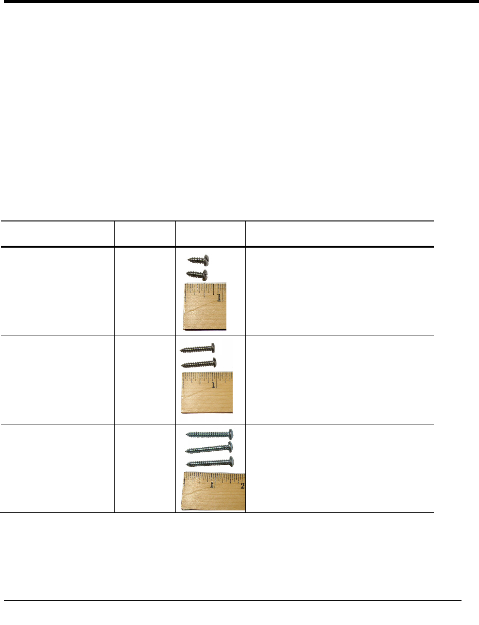
Mounting Screw Specifications
Application Itron Part
Number
Description
To mount adapter plates on
pipe brackets
575-9930-016
8-16 x 1/2-inch length, type 8 slotted pan-head
tapping screw, corrosion-resistant steel
To mount the module on
adapter plates
575-9930-032
8-16 x 1-inch type 8, slotted pan-head tapping screw,
corrosion-resistant steel
To mount the module on sheet
metal surfaces (to mount
modules to wood surfaces, a
comparable wood screw is
required)
SCR-0009-001
10-16 x 1 1/2-inch type AB thread for sheet metal,
Phillips pan-head tapping screw, corrosion-resistant
steel
CHAPTER 2
Mounting the 100T
-HON Telemetry Module
Mounting the 100T-HON Telemetry Module
TDC
-1346-000 100T-HON Honeywell Telemetry Module Installation Guide 9
Proprietary and Confidential
Mounting Installation Considerations
Select a proper mounting location. Itron recommends mounting the module in close proximity to the meter or
instrument. Some applications may require an extended cable-length.
Mount the module in a vertical position with the label directional arrow pointed upward.
Caution Upright vertical positioning is very important because:
• 100T-HON modules are designed with the antenna in a vertical direction so
the antenna is parallel to the reading device (which has a vertical antenna).
Matching antenna polarity can greatly affect RF performance and enable easy
module reading.
• 100T-HON modules are designed so the tilt tamper is vertical. It is important to
maintain vertical positioning in the field to enable tilt tamper stability.
Warning Do not mount the module in an orientation other than vertical (module label arrow
pointed upward). Violating the mounting orientation requirements will void the product
warranty.
Mounting the 100T-HON Telemetry Module on a Pipe
The following items are required to mount the 100T-HON telemetry module on a pipe or vertical flat surface
(wall):
Itron Part
Number
Description
TEL-1000-001
100T-HON telemetry module
CFG-0005-003 Remote Mount Installation Kit
Kit includes:
(2) two band clamps
(2) two tamper seals
pipe bracket
cable ties
adapter plate
Screws:
(2) 1/2-inch, to attach the adapter plate to the pipe bracket
(2) 1-inch, to attach the module to the adapter plate
(3) 1-1/2-inch, to attach the module to a vertical surface (wall)
Warning Install the 100T-HON telemetry module in an upright position. Any position other than
upright, can negatively affect radio performance and reduce battery life.

Mounting the 100T-HON Telemetry Module
TDC
-1346-000 100T-HON Honeywell Telemetry Module Installation Guide 10
Proprietary and Confidential
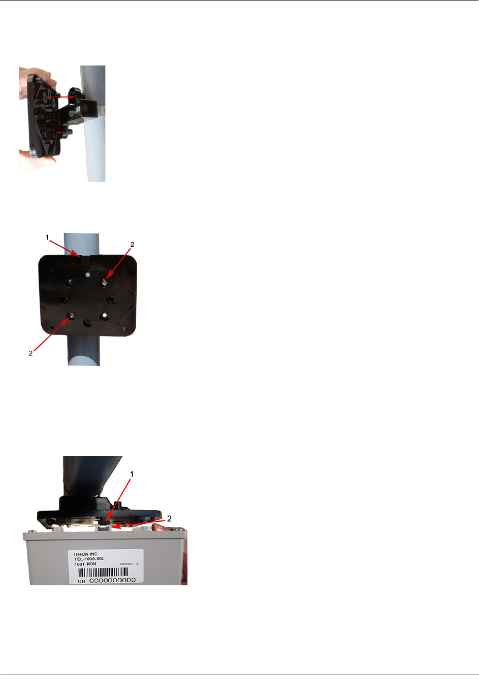
To mount the pipe bracket on a vertical pipe
1. Remove the pipe bracket and band clamp from the Remote Mount Installation Kit (Itron part number
CFG-0005-003).
2. Loosen the band clamp screw until the end of the band releases.
3. Push the end of the clamp's band through the holes in the pipe bracket. The pipe bracket must be oriented
as shown below.
4. Place the band clamp around the pipe. The band will loosely wrap around the pipe. Push the end of the
band through the band clamp screw assembly. Turn the band clamp's screw assembly to fit into the pipe
bracket opening. Tighten the clamp screw until the band clamp is secure on the pipe.
Caution The pipe bracket must fit firmly against the pipe to prevent slippage.
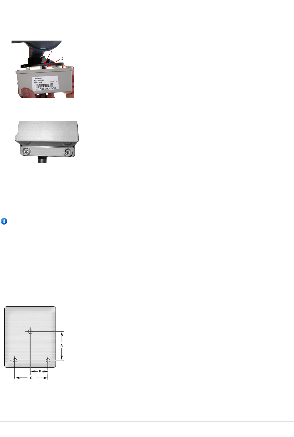
To mount the adapter plate on the pipe bracket
Caution Vertical mounting position is important to maximize RF performance. Mount the 100T-HON
telemetry module with the module label arrow pointing up. The module's arrow must never point to either
side or upside down. The module tilt tamper functionality is designed to operate with the module installed
vertically.
Mounting the 100T-HON Telemetry Module
TDC
-1346-000 100T-HON Honeywell Telemetry Module Installation Guide 11
Proprietary and Confidential
1. Place the adapter plate on the pipe bracket with the mounting lug at the top or bottom. The adapter plate
screw bosses fit into the pipe bracket recess.
2. Ensure the adapter plate is positioned as shown below with the mounting lug (1) at the top or bottom. To
install the adapter plate on a vertical pipe, use the two shortest (1/2-inch) adapter plate mounting screws
from the installation kit. Place the mounting screws (2) in the holes shown below.
3. Tighten both screws securely in an alternating pattern. Tighten to 9 - 12 inch-pounds torque.
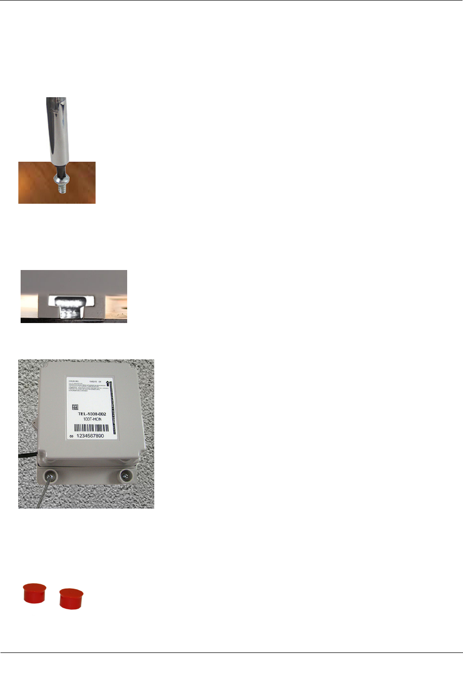
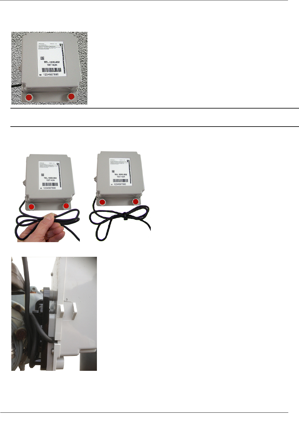
To mount the 100T-HON telemetry module on the adapter plate
1. Place the back of the module against the face of the adapter plate. The adapter plate mounting lug (1) must
be positioned just above the module mounting lug recess (2).
Mounting the 100T-HON Telemetry Module
TDC
-1346-000 100T-HON Honeywell Telemetry Module Installation Guide 12
Proprietary and Confidential
2. Slide the module up onto the adapter plate mounting lug until the mounting lug (1) is as far as possible
inside the module mounting lug recess (2).
3. Align the module back plate mounting holes with the pipe mount adapter plate holes. Install the two one-
inch mounting screws from the installation kit.
4. Tighten the module mounting screws evenly in an alternating fashion. Torque the screws to 9 - 12 inch-
pounds of pressure.
Mounting the 100T-HON Telemetry Module on a Wall or Other Flat Vertical
Surface
Note For easier installation, drill three pilot holes in the mounting surface (use the correct size drill bit to
accommodate the module mounting screws [see the drilling template below]). The drilled pilot holes for
the two bottom screws must be on a horizontal line. To mount the module on a sheet metal surface, use
the mounting screws included with the Mounting kit. Use a comparable wood screw to mount the module
on a vertical wood surface.
Carefully select a mounting location free from electrical wires. The mounting location must have the
proper clearance to accommodate the 1-1/2-inch module mounting screws so nothing is damaged by the
drill or mounting screws.
Module drilling template
A 3 inches
B 1-11/16 inches
C 3-3/8 inches
Mounting the 100T-HON Telemetry Module
TDC
-1346-000 100T-HON Honeywell Telemetry Module Installation Guide 13
Proprietary and Confidential
To mount the 100T-HON telemetry module on a wall or other flat vertical surface
1. Using one of the three 1-1/2-inch mounting screws from the module installation kit, turn the mounting
screw for the mounting lug (top of the module) part way into the mounting surface.
2. Place the 100T-HON telemetry module mounting lug recess (on the top of the module's backplate) just
under the screw head.
3. Slide the module upward until the screw head fits completely inside the mounting lug recess. Several
adjustments may be necessary to properly position the screw for module mounting.
4. Install the bottom two mounting screws. Fasten the screws in an alternating pattern until fully tightened to
secure the module firmly in position.
To install tamper seals and cable ties
1. Place the new tamper seals from the module installation kit over the 100T-HON telemetry module
mounting screws.
Mounting the 100T-HON Telemetry Module
TDC
-1346-000 100T-HON Honeywell Telemetry Module Installation Guide 14
Proprietary and Confidential
2. Firmly push both tamper seals all the way into place with a 1/4-inch nut driver or similar blunt tool.
Note A tamper seal is fully seated when the top of the tamper seal is approximately 1/16-inch below the
top of the screw recess.
3. To reduce the risk of cable damage, secure the excess module cable with the cable ties from the module
installation kit. Pull the cable tight. Remove and properly dispose the excess cable tie.
4. Alternatively, the cable may be wrapped around the adapter plate as shown.
100T-HON telemetry module installation on a vertical flat surface or wall is complete.
TDC
-1346-000 100T-HON Honeywell Telemetry Module Installation Guide 15
Proprietary and Confidential
This section provides the instructions to install the 100T-HON telemetry module on Honeywell Instruments:
• Mini-AT
• Mini-Max
• ERX
Mini-AT Mini-Max ERX
Installation Overview
Installing the 100T-HON telemetry module to a Honeywell Mercury instrument involves five tasks:
1. Programming the instrument (for more information, see Programming the Mercury Instrument Parameters
on page 15 or reference the Mercury Instrument Programming Guide for more information).
2. Installing Mercury retrofit parts (if required).
3. Attaching the 100T-HON telemetry module to a pipe or vertical flat surface (wall) (for more information,
see Mounting the 100T-HON Telemetry Module on page 8).
4. Connecting the 100T-HON telemetry module to the Mercury Instrument Volume Corrector (see To wire
the 100T-HON telemetry module to the Mercury Instrument).
5. Programming the 100T-HON telemetry module (see Programming the 100T-HON Telemetry Module).
Programming the Mercury Instrument Parameters
The Honeywell Mercury Instrument configuration must support the connection of the 100T-HON telemetry
module. Complete instrument configuration using a separate application (not using the Itron network,
applications, or 100T-HON).
CHAPTER 3
Connecting and Configuring the Module and Instrument

Connecting and Configuring the Module and Instrument
TDC
-1346-000 100T-HON Honeywell Telemetry Module Installation Guide 16
Proprietary and Confidential
Honeywell Instrument Call-In Configuration
The installer must configure the Honeywell Instrument properly to support the instrument-controlled alarm
call-in feature. Automatic instrument configuration is not supported by the 100T-HON module. Configure the
call-in feature using the following item codes.
Mini-Max
Item Number
Item Description
Set Value
Value Meaning
126 Instrument baud rate 0 9600 Baud
139 Serial link access 0 Full read/write
238 Serial Log Trigger 1 Active
333 Call-in trigger 1 Alarm call-in enabled
336 Call-in retry by 0 Host
405 Call-in delay time 4 4 seconds
486 Modem AT enable 1 call-in using AT commands
491 Modem init-string ATE0Q0V0X4
-
492 Modem dial string ATDT -
493 Alarm call-in phone number 924-9900 -
494 Modem hangup string ATH0 -
495 Modem retry interval A 5 5 minutes
496 Modem retry interval B 1440 1440 minutes
497 Modem retry A count 3 3 retries
821 Modem wake-up delay 50 5 seconds
Mini-AT
Item Number
Item Description
Set Value
Value Meaning
126 Instrument baud rate 0 9600 Baud
139 Serial link access 0 Full read/write
238 Serial Log Trigger 1 Active
333 Call-in trigger 1 Alarm call-in enabled
336 Call-in retry by 0 Host
405 Call-in delay time 4 4 seconds
486 Modem AT enable 1 call-in using AT commands
491 Modem init-string ATE0Q0V0X4
-
492 Modem dial string ATDT -
Connecting and Configuring the Module and Instrument
TDC
-1346-000 100T-HON Honeywell Telemetry Module Installation Guide 17
Proprietary and Confidential
Mini-AT
Item Number
Item Description
Set Value
Value Meaning
493 Alarm call-in phone number 924-9900 -
494 Modem hangup string ATH0 -
495 Modem retry interval A 5 5 minutes
496 Modem retry interval B 1440 1440 minutes
497 Modem retry A count 3 3 retries
821 Modem wake-up delay 50 5 seconds
ERX
Item Number
Item Description
Set Value
Value Meaning
333 Call-in trigger 1 Alarm call-in enabled
336 Call-in retry by 0 Host
588 Instrument baud rate 0 9600 baud
602 Serial Log Trigger 1 Active
780 Modem init string ATE0Q0V0X4 -
781 Modem dial string ATDT -
782 Modem hangup string ATH0 -
784 Alarm call-in phone number 1 924-9900 -
785 Alarm call-in phone number 2 <BLANK> -
786 Modem retry interval A 5 5 minutes
787 Modem retry interval B 1440 1440 minutes
788 Modem retry A count 3 3 retries
789 Modem AT enable 1 Call-in using AT commands
821 Modem wake-up delay 50 5 seconds
Connecting the 100T-HON Telemetry Module to the Instrument
The 100T-HON module has a single serial RS232 interface to the Honeywell instrument. Some of the
compatible instruments (ERX, MMX) require the installation of an internal CMOS to RS232 adapter board. If
the adapter board is not installed in the field units, contact Honeywell to obtain the board.
Serial access to the Honeywell instrument requires an instrument access code. The Honeywell instrument
requires this access code from the 100T-HON module to log on to the instrument prior to every data read.
You must program the access code into the 100T-HON module at installation time.
Connecting and Configuring the Module and Instrument
TDC
-1346-000 100T-HON Honeywell Telemetry Module Installation Guide 18
Proprietary and Confidential
The Mechanical Uncorrected Volume Switch
The 100T-HON telemetry module supports a connection to a mechanical uncorrected volume switch output
from the Honeywell Mini-Max and Mini-AT instruments. This switch output allows the 100T-HON telemetry
module to independently count the mechanically uncorrected volume, even if the instrument losses power.
To collect mechanical uncorrected volume data, the following must be true:
• The instrument must have the mechanical pulse output option board installed.
• The module’s mechanical pulser cable must be connected to the Honeywell instrument.
• The module must be configured to use the mechanical uncorrected volume as its channel 2 data stream.
The 100T-HON telemetry module pulse counter supports a maximum of 1 pulse per second with at least 1/3
second on, and 1/3 second off.
Electronic Corrected Pulse Output
The 100T-HON telemetry module does not provide a connection to an instrument electronic corrected pulse
output. Electronic corrected volume data is collected through the serial connection.
Electronic Uncorrected Pulse Output
The 100T-HON telemetry module does not include a connection to an instrument electronic uncorrected pulse
output. Electronic uncorrected volume data is collected through the serial connection.
Alarm Switch
The 100T-HON telemetry module does not include a connection to an instrument alarm switch. The
instrument alarm data is collected through the serial connection.
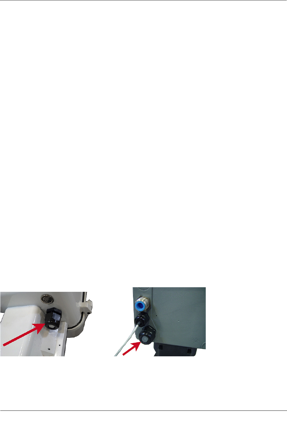
Honeywell Instrument Cable Connections
The 100T-HON telemetry module cable enters the Honeywell instrument through a watertight compression
connector on the back of the instrument.
Mini-AT compression connector ERX/MiniMax compression connector
The 100T-HON telemetry module connects to the Honeywell Mini-AT, MiniMax, and ERX instruments.
Connecting and Configuring the Module and Instrument
TDC
-1346-000 100T-HON Honeywell Telemetry Module Installation Guide 19
Proprietary and Confidential
The 100T-HON telemetry module includes a single 5-foot cable. The cable accommodates the RS232 serial
connection or connection to the mechanical uncorrected volume.
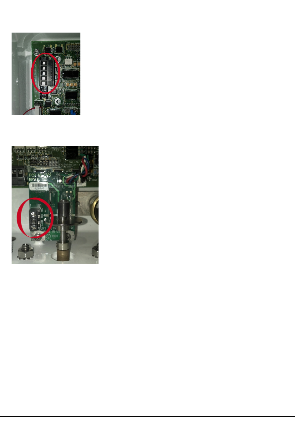
100T-HON telemetry module to Mercury Instrument Connections
Wire Color
Wire Function
Instrument Connection
White Pulse Interface (Count Sense) Pulser Board--COM
Red Pulse Interface (Count Enable) Pusler Board - NO
Black RS232 Ground RS232 Main or Adapter Board--COM
Green RS232 Tx RS232 Main or Adapter Board--Tx
Yellow RS232 Rx RS232 Main or Adapter Board--Rx
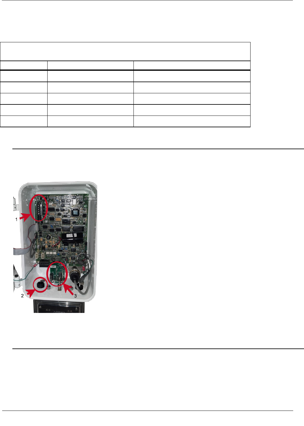
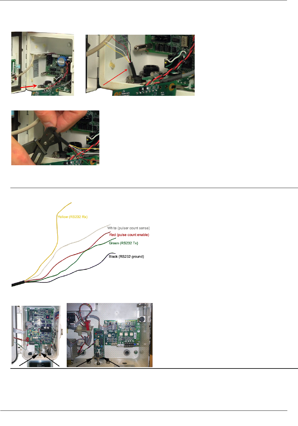
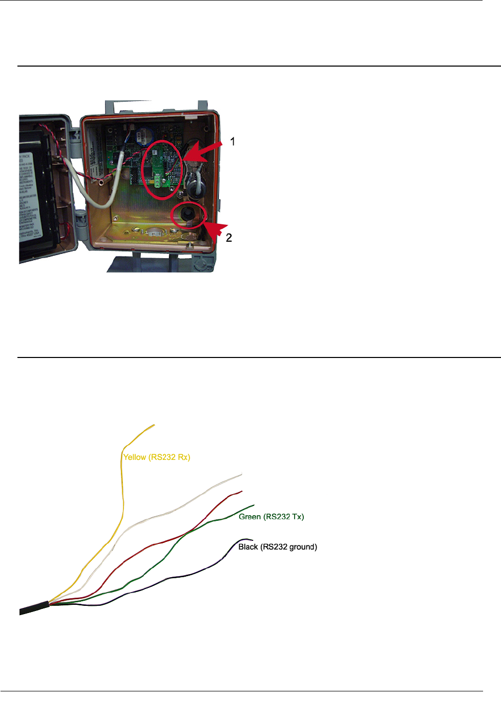
To connect the 100T-HON telemetry module to the Mini-AT Mercury Instrument
If the 100T-HON telemetry module will be connected to the Honeywell Mini-AT, the module must have
an RS232 connection to the instrument. (Optional) The module connection to the Mini-AT may be a
mechanical uncorrected volume pulser connection.
1. RS232 Terminal Block
2. Compression Connector
3. Pulser Board
Connecting and Configuring the Module and Instrument
TDC
-1346-000 100T-HON Honeywell Telemetry Module Installation Guide 20
Proprietary and Confidential
1. Insert the 100T-HON telemetry module cable into the instrument's compression connector.
2. Strip five inches of the outer insulation from the 100T-HON telemetry module cable.
3. Individually strip 1/4-inch individual wire insulation from the red, white, yellow, black, and green lead
wires. Complete each connection prior to stripping the next wire.
Warning Strip wires one at a time to prevent shorting stripped wires.
Caution Keep wires away from the rotating magnetic spindle in the Mercury Instrument.
Connecting and Configuring the Module and Instrument
TDC
-1346-000 100T-HON Honeywell Telemetry Module Installation Guide 21
Proprietary and Confidential
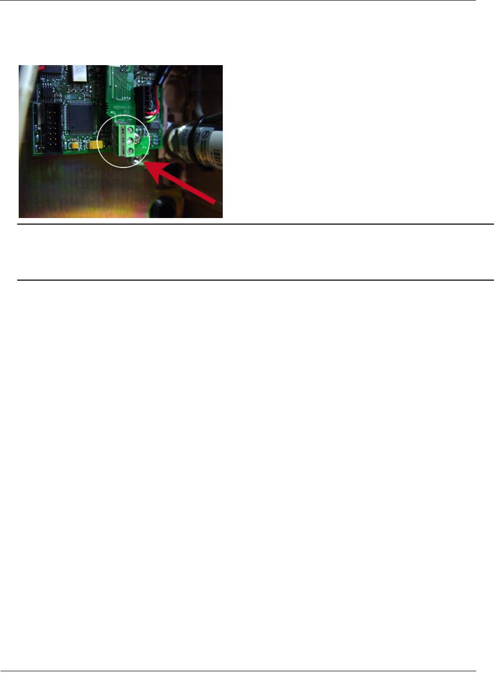
4. Connect the 100T-HON telemetry module to the instrument RS232 terminal block connections.
5. (Optional) To connect the 100T-HON telemetry module for mechanical uncorrected volume pulser data,
connect the 100T-HON telemetry module to the three-wire screw terminal connector on the mechanical
pulser board. Connect only to the NO and COM.
6. After the 100T-HON telemetry module is wired to the instrument, see Mounting the 100T-HON
Telemetry Module for module mounting instructions.
Connecting and Configuring the Module and Instrument
TDC
-1346-000 100T-HON Honeywell Telemetry Module Installation Guide 22
Proprietary and Confidential
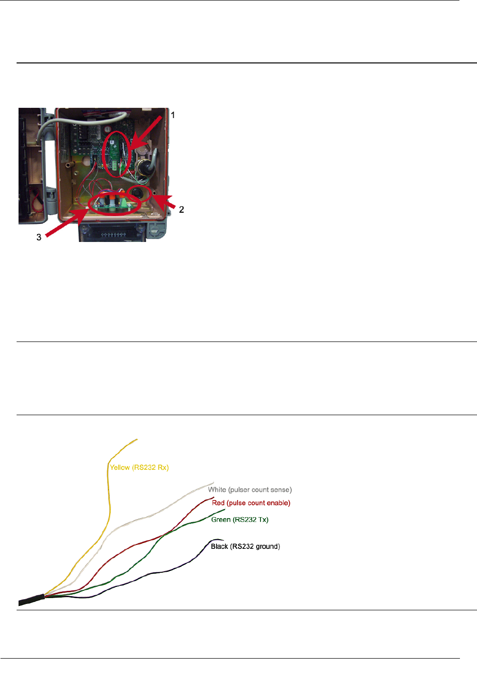
To connect the 100T-HON telemetry module to the Mini-Max Mercury Instrument
Note If the 100T-HON telemetry module will be connected to the Honeywell Mini-Max, the module
must have an RS232 connection to the instrument. (Optional) The module connection to the Mini-Max
may be a mechanical uncorrected volume pulser connection.
1. RS232 Terminal Block
2. Compression Connector
3. Pulser Board
Note For more information about routing the cable through the compression connector and stripping the
cable's outer jacket, refer to To connect the 100T-HON telemetry module to the Mini-AT Mercury
Instrument on page 19.
1. Insert the 100T-HON telemetry module cable into the instrument's compression connector.
2. Strip five inches of the outer insulation from the 100T-HON telemetry module cable.
3. Individually strip 1/4-inch individual wire insulation from the red, white, yellow, black, and green lead
wires.
Warning Strip wires one at a time to prevent shorting stripped wires.
Connecting and Configuring the Module and Instrument
TDC
-1346-000 100T-HON Honeywell Telemetry Module Installation Guide 23
Proprietary and Confidential
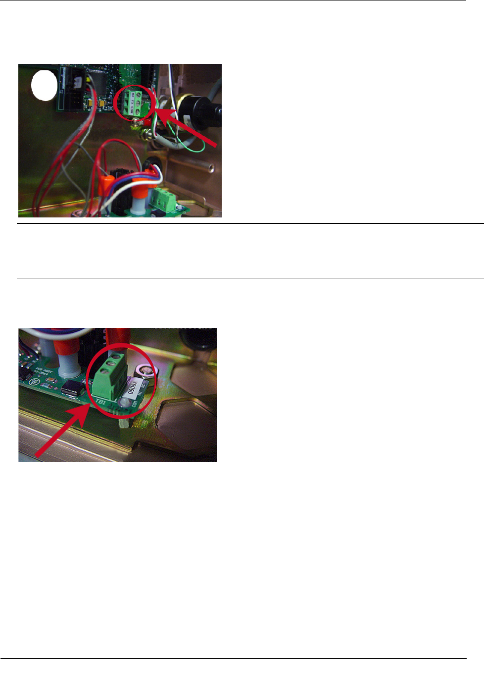
4. Connect the 100T-HON telemetry module to the instrument RS232 terminal block connections on the
CMOS to RS232 adapter board. Connect Rx, Tx, and COM (Gnd).
Note The Mini-Max may have the RS232 adapter board connected to the external RS232 case connector.
The external case connector must be replaced with the connector capable of using an external shorting
plug and the RS232 connection. The 100T-HON telemetry module wires are gel connected to the internal
wires and the external shorting plug is installed.
5. (Optional) To connect the 100T-HON telemetry module for mechanical uncorrected volume pulser data,
connect the 100T-HON telemetry module to the three-wire screw terminal connector on the mechanical
pulser board. Connect only to the NO and COM.
Connecting and Configuring the Module and Instrument
TDC
-1346-000 100T-HON Honeywell Telemetry Module Installation Guide 24
Proprietary and Confidential
To connect the 100T-HON telemetry module to the ERX Mercury Instrument
Note If the 100T-HON telemetry module is connected to the ERX Mercury Instrument, the connection is
only made to the RS232 connection in the instrument.
1. RS232 Terminal Block
2. Compression Connector
Note For more information about routing the cable through the compression connector and stripping the
cable's outer jacket, refer to To connect the 100T-HON telemetry module to the Mini-AT Mercury
Instrument on page 19
1. Insert the 100T-HON telemetry module cable into the instrument's compression connector.
2. Strip five inches of the outer insulation from the 100T-HON telemetry module cable.
3. Strip 1/4-inch individual wire insulation from the yellow, black, and green lead wires.
Connecting and Configuring the Module and Instrument
TDC
-1346-000 100T-HON Honeywell Telemetry Module Installation Guide 25
Proprietary and Confidential
4. Connect the 100T-HON telemetry module to the instrument RS232 terminal block connections on the
CMOS to RS232 adapter board. Connect Rx, Tx, and COM (Gnd).
Note The ERX may have the RS232 adapter board connected to the external RS232 case connector. The
external case connector must be replaced with the connector capable of using an external shorting plug
and the RS232 connection. The 100T-HON telemetry module wires are gel connected to the internal wires
and the external shorting plus is installed.
5. To protect the unused red and white wires from shorting inside the instrument, place and compress a gel
connector over each red and white wire.

TDC
-1346-000 100T-HON Honeywell Telemetry Module Installation Guide 26
Proprietary and Confidential
After the 100T-HON telemetry module is installed, you must program the module using an Itron handheld or
900MHz Belt Clip Radio and your PC loaded with Field Deployment Manager (FDM) software. FDM
supports configuration of the following parameters:
• (Optional) Injecting ChoiceConnect security keys.
• Setting the fixed network or mobile operation mode (setting the operation mode establishes the transmit
power, default packet type, and BUP rates).
• Setting the Honeywell communication access code.
• Setting the utility ID.
• Setting the 100T-HON telemetry module time.
• Setting connected device-specific parameters:
• Honeywell EVC devices
o Configure channel 2 (for none, electronic uncorrected volume, or mechanical uncorrected
volume).
o For mechanical uncorrected volume channel 2 only (implies the existence of an uncorrected
mechanical input):
• initial index read
• drive rate
Configure gas day take (GDT) options.
• Enable or disable GDT
• GDT capture time
• GDT BUP frequency
• Number of GDT transmissions
Caution You must program the 100T-HON telemetry module before use.
CHAPTER 4
Programming the 100T
-HON Telemetry Module
Programming the 100T-HON Telemetry Module
TDC
-1346-000 100T-HON Honeywell Telemetry Module Installation Guide 27
Proprietary and Confidential
Program the 100T-HON telemetry modules using:
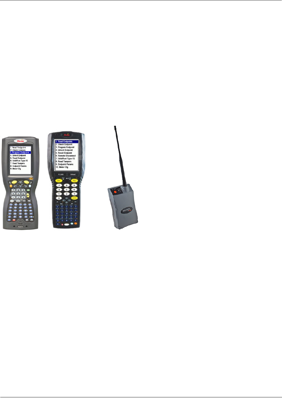
• An FC200SR handheld computer with Field Deployment Manager (FDM) software version 3.2 or higher
or
• An FC300 with SRead handheld computer with Field Deployment Manager (FDM) software version 3.2
or higher
or
• A 900MHz Belt Clip Radio and your laptop with Field Deployment Manager (FDM) software version 3.2
or higher. The Belt Clip Radio connects to the user-supplied laptop using a USB cable or Bluetooth.
See the Field Deployment Manager Endpoint Tools Mobile Application Guide (TDC-0934) for more complete
programming information.
FC200SR FC300 with SRead 900MHz Belt Clip Radio
To program the 100T-HON telemetry module
1. Program the meter drive rate into the 100T-HON telemetry module using a handheld computer or Belt
Clip Radio and laptop computer. For all programming and Check Endpoint operations using a handheld
computer, hold the handheld as close to vertical as possible. For best success, keep the handheld within six
feet of the target endpoint. Verify you have the correct programming mode (Fixed Network Mode, or
Mobile/Handheld Mode) for your application. Programming parameters are based on the configuration file
loaded into the programming device.
2. To verify 100T-HON telemetry module installation and configuration, FDM supports the ability to read
electronic corrected volume (for Honeywell EVC devices only), read channel 2 if available (electronic
uncorrected or mechanical uncorrected volume—for Honeywell EVC devices only), get tampers, perform
check ERT functions, and perform network coverage tool (NCT) operation.

Programming the 100T-HON Telemetry Module
TDC
-1346-000 100T-HON Honeywell Telemetry Module Installation Guide 28
Proprietary and Confidential
To verify proper communications
Note Itron recommends the following operations to verify communications between the 100T-HON
telemetry module and the Mercury Instrument.
1. For an EVC instrument: send a channel 1 EMMIMO read immediately to collect an electronic corrected
read. Compare the collected read to the Mercury Instrument LCD reading.
2. For and EVC instrument with channel 2 data not set to None: send a channel 2 EMIMO to collect an
uncorrected read. Compare the collected read to the Mercury Instrument meter dial.
3. Confirm the Invalid Access Code tamper is not set. If the tamper is set, check the wire connections and
repeat the EMIMO and tamper check.