Itron 100THONA AMR transceiver device for utility gas/telemetry meters User Manual 100T HON Telemetry Module Installation Guide
Itron Inc AMR transceiver device for utility gas/telemetry meters 100T HON Telemetry Module Installation Guide
Itron >
Users Manual


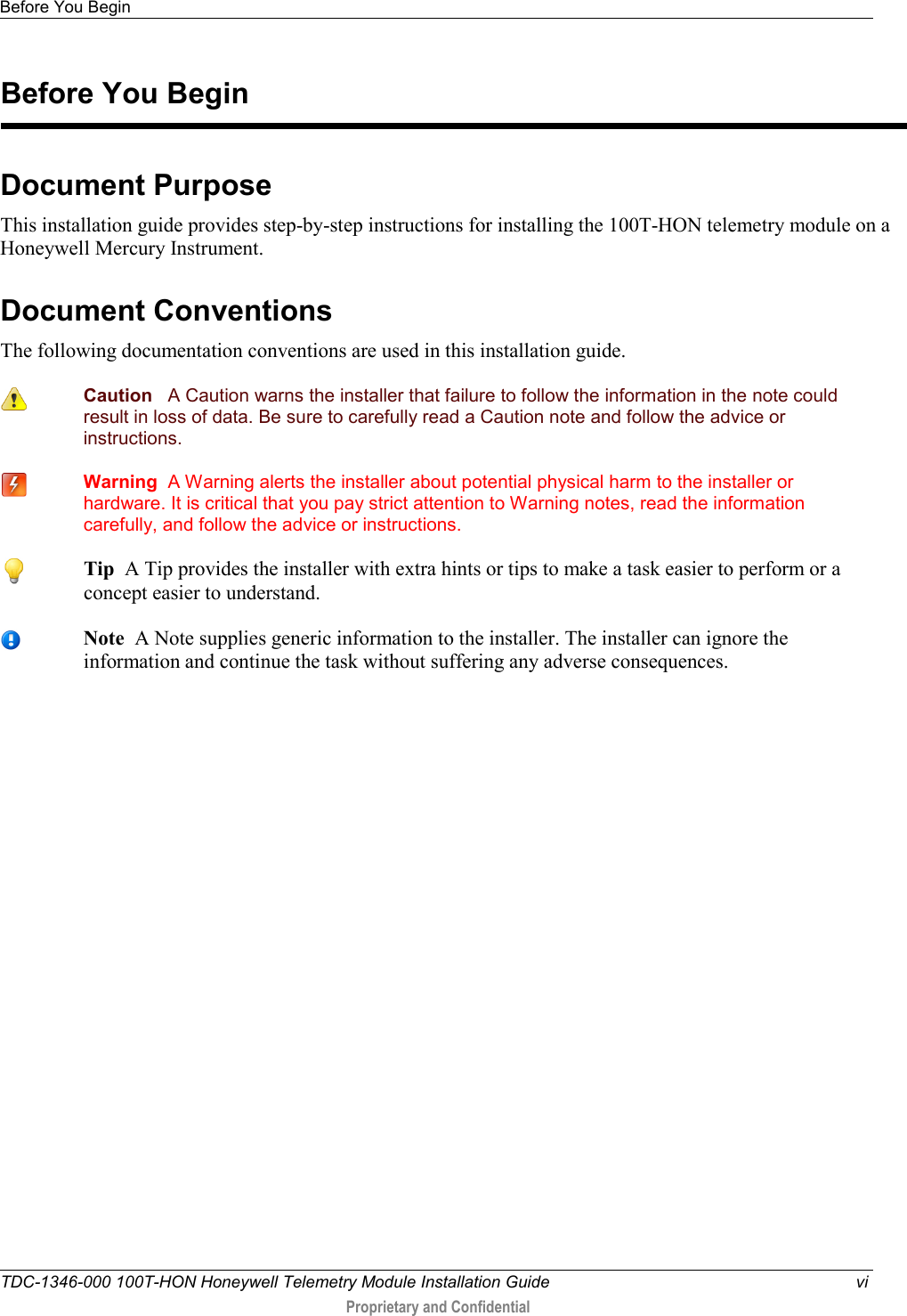

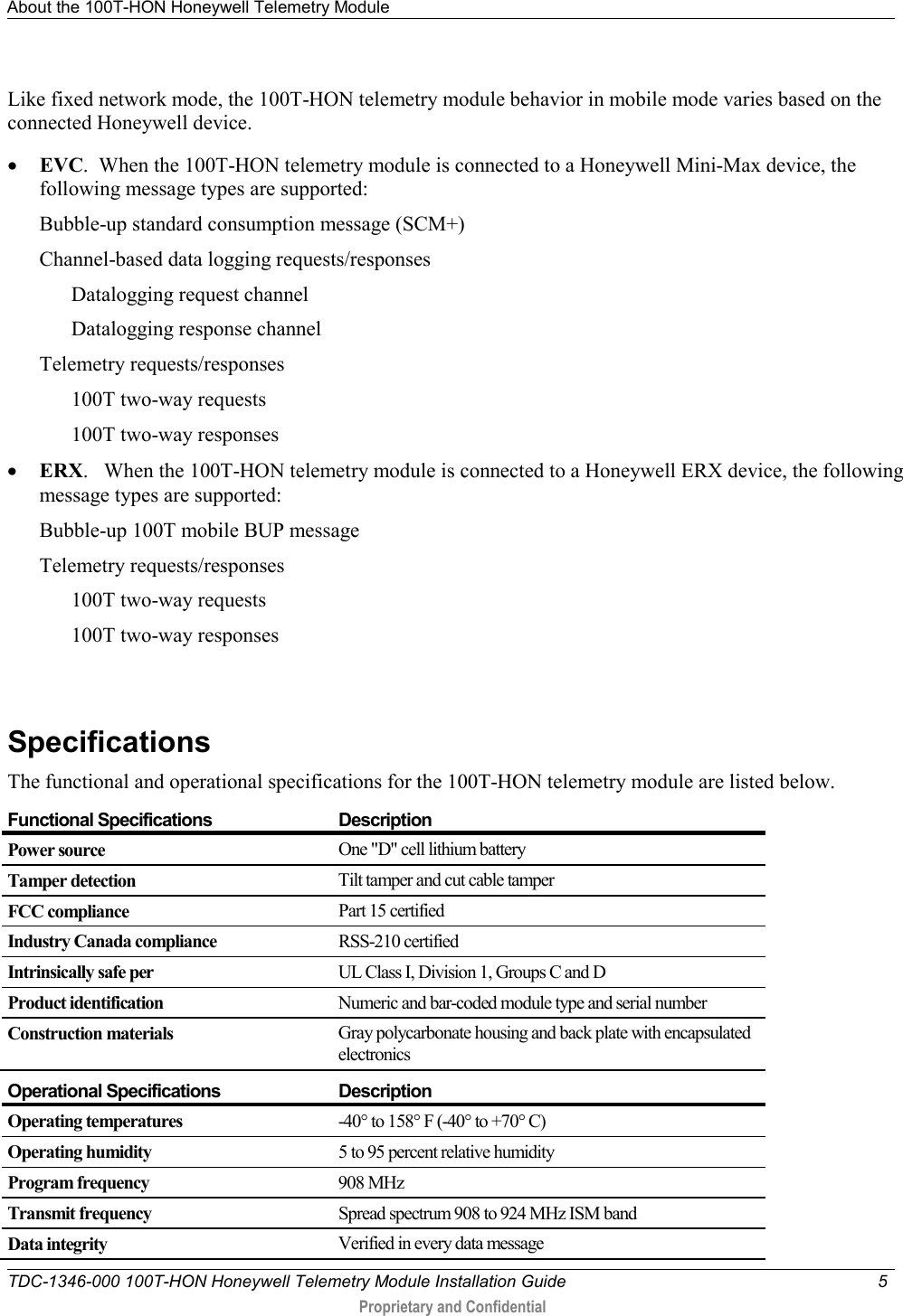
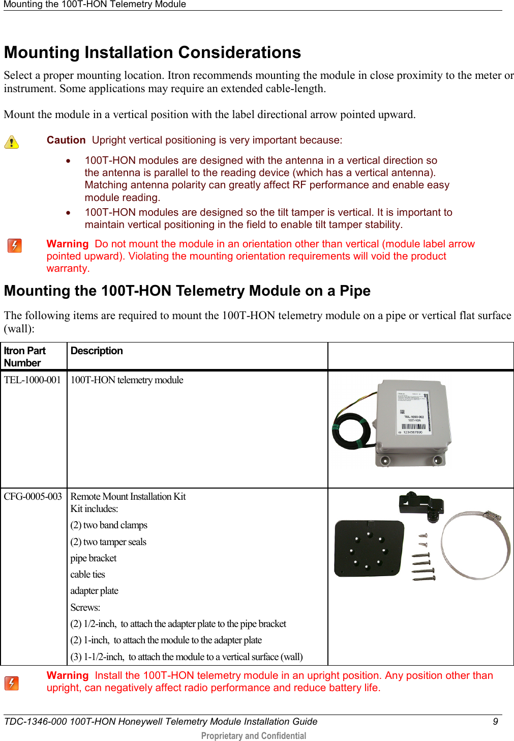
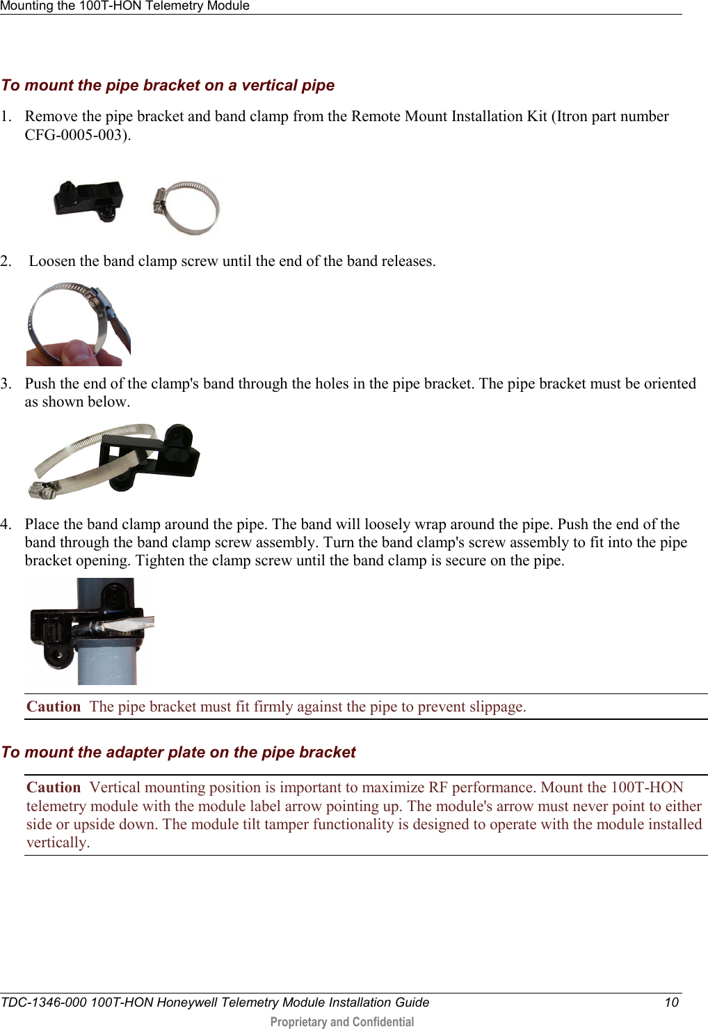
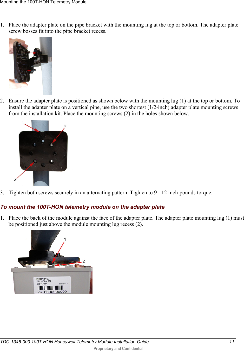
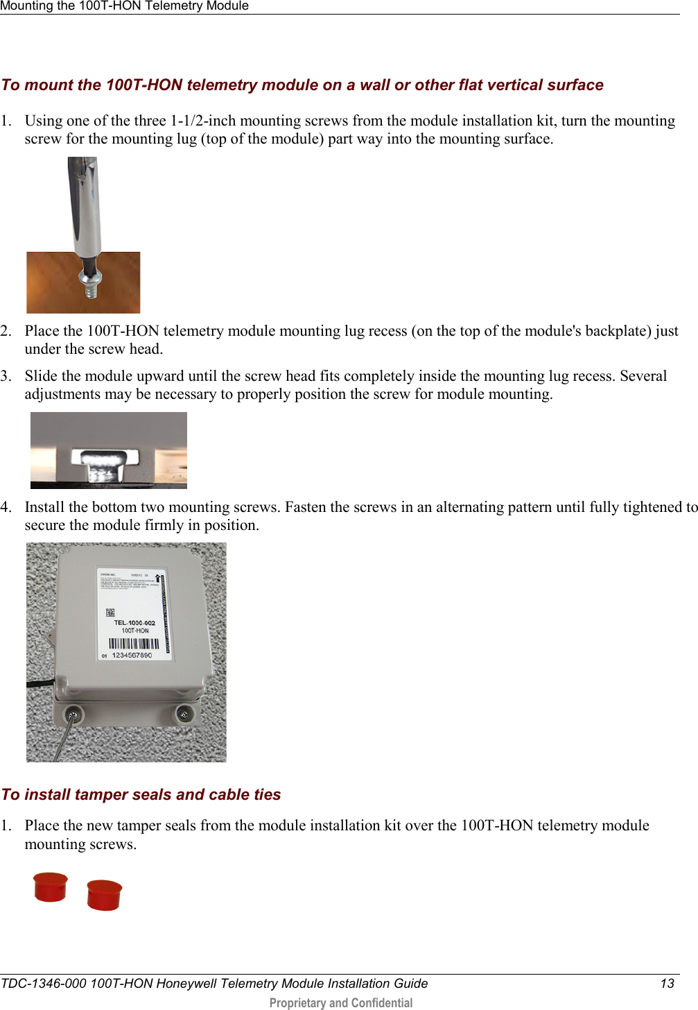
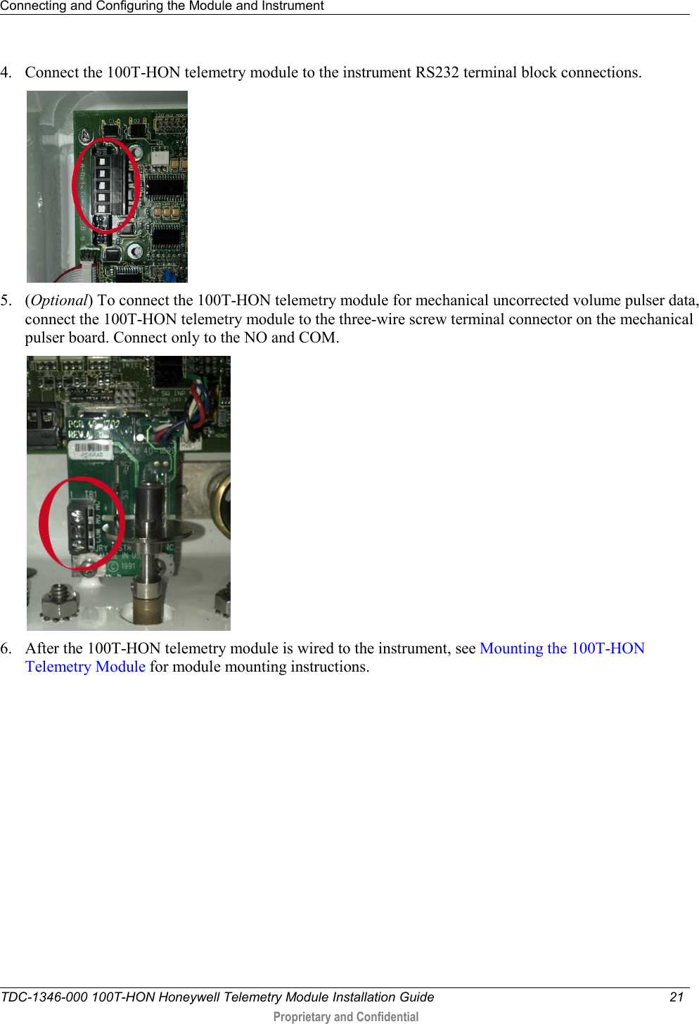
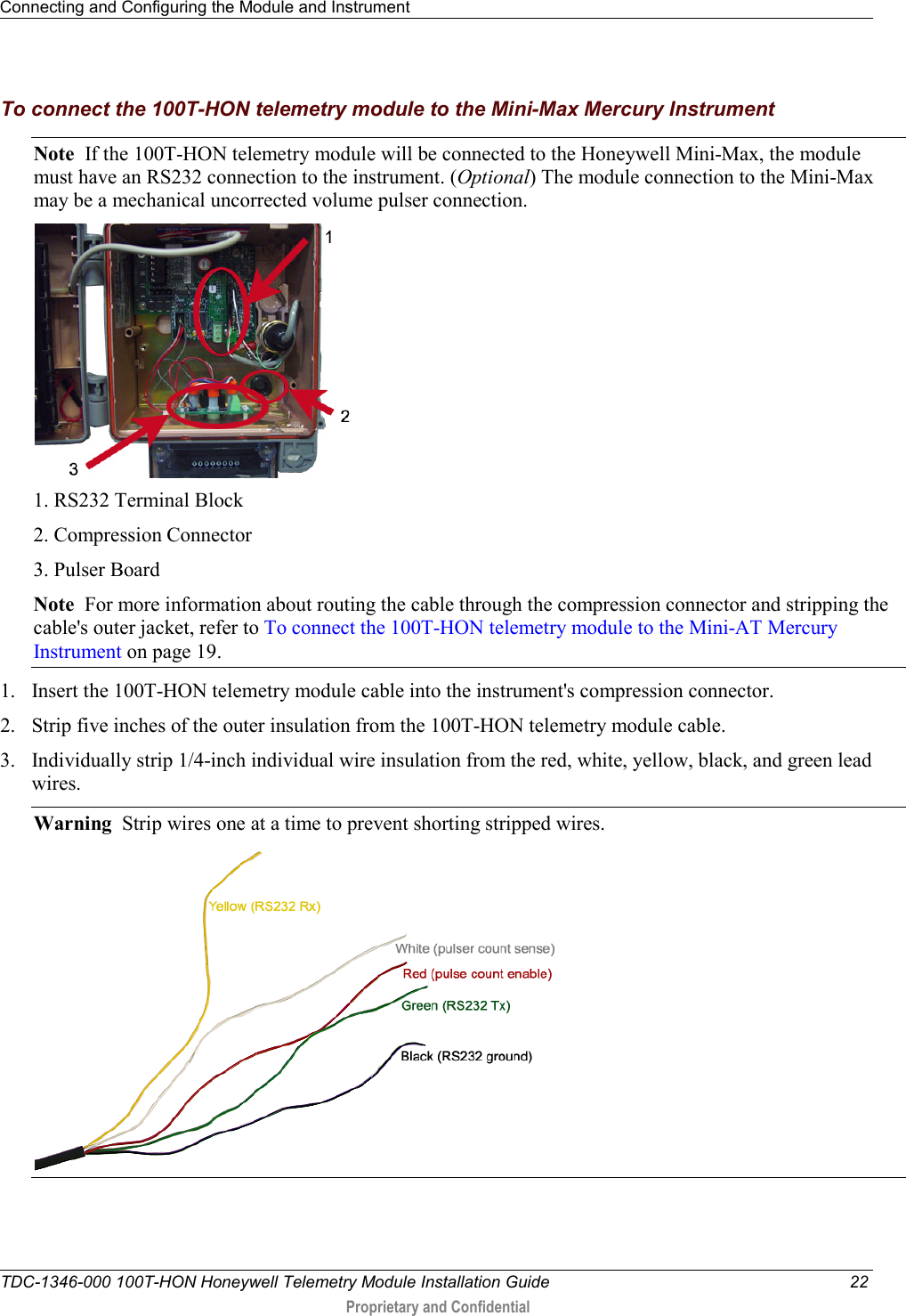
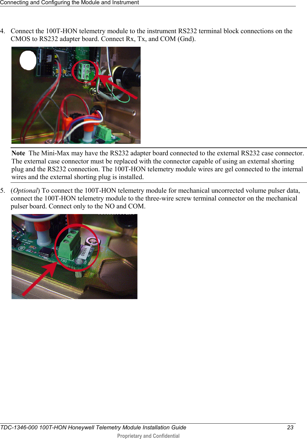
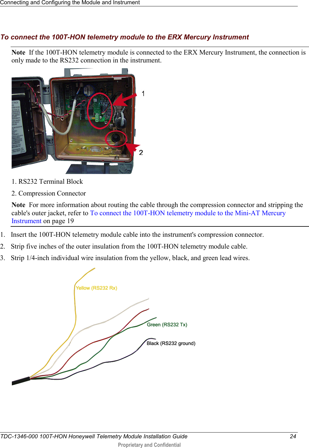
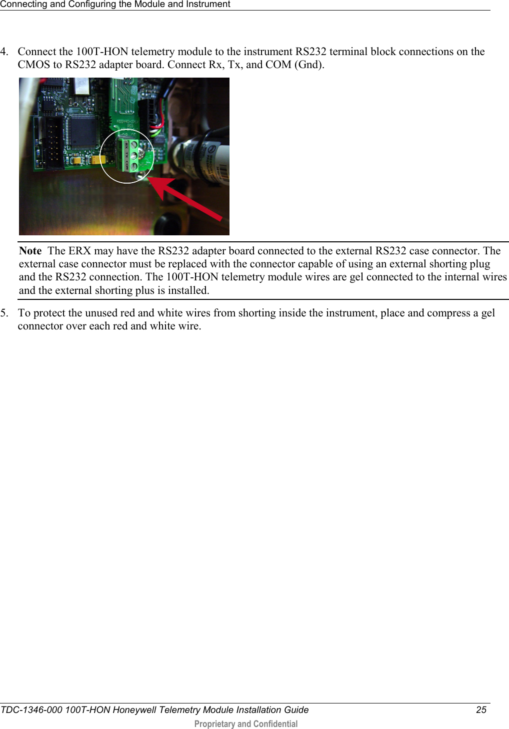
![Mounting the 100T-HON Telemetry Module TDC-1346-000 100T-HON Honeywell Telemetry Module Installation Guide 12 Proprietary and Confidential 2. Slide the module up onto the adapter plate mounting lug until the mounting lug (1) is as far as possible inside the module mounting lug recess (2). 3. Align the module back plate mounting holes with the pipe mount adapter plate holes. Install the two one-inch mounting screws from the installation kit. 4. Tighten the module mounting screws evenly in an alternating fashion. Torque the screws to 9 - 12 inch-pounds of pressure. Mounting the 100T-HON Telemetry Module on a Wall or Other Flat Vertical Surface Note For easier installation, drill three pilot holes in the mounting surface (use the correct size drill bit to accommodate the module mounting screws [see the drilling template below]). The drilled pilot holes for the two bottom screws must be on a horizontal line. To mount the module on a sheet metal surface, use the mounting screws included with the Mounting kit. Use a comparable wood screw to mount the module on a vertical wood surface. Carefully select a mounting location free from electrical wires. The mounting location must have the proper clearance to accommodate the 1-1/2-inch module mounting screws so nothing is damaged by the drill or mounting screws. Module drilling template A 3 inches B 1-11/16 inches C 3-3/8 inches](https://usermanual.wiki/Itron/100THONA/User-Guide-2034218-Page-18.png)