Itron 100WB AMR transceiver device for utility meters User Manual
Itron Inc AMR transceiver device for utility meters Users Manual
Itron >
Contents
- 1. Users Guide
- 2. Users Manual
Users Manual

Water Solutions
100W and 100WP Datalogging ERT Module
Installation Guide
TDC-0909-003

Identification
100W and 100WP Datalogging ERT Module Installation Guide
06/29/2011 TDC-0909-003
Copyright
© 2010 - 2011 Itron, Inc. All rights reserved.
Confidentiality Notice
The information contained herein is proprietary and confidential and provided subject to the condition that (i) it is held in confidence except to the extent required otherwise by law and (ii) it is
used only for the purposes described herein. Any third party given access to this information is similarly bound in writing.
Compliance Statement
This device complies with Part 15 of the FCC Rules. These limits are designed to provide reasonable protection against harmful interference in a residential installation. Operation is subject to
the following two conditions:
• This device may not cause harmful interference.
• This device must accept any interference that may cause undesirable operation.
This device must be permanently mounted such that it retains a distance of 20 centimeters (7.9 inches) from all persons in order to comply with FCC RF exposure levels.
Compliance Statement
This equipment complies with policies RSS-210 and RSS-GEN of
the Industry Canada rules.
Operation is subject to the following two conditions:
(1) this device may not cause interference, and
(2) this device must accept any interference, including
interference that may cause undesired operation of the device.
Déclaration de conformité
Le présent appareil est conforme aux CNR d'Industrie Canada applicables aux
appareils radio exempts de licence. L'exploitation est autorisée aux deux conditions
suivantes :
(1) l'appareil ne doit pas produire de brouillage, et
(2) l'utilisateur de l'appareil doit accepter tout brouillage radioélectrique subi, même si le
brouillage est susceptible d'en compromettre le fonctionnement.
Compliance Statement Canada
Under Industry Canada regulations, this radio transmitter may only
operate using an antenna of a type and maximum (or lesser) gain
approved for the transmitter by Industry Canada. To reduce
potential radio interference to other users, the antenna type and its
gain should be so chosen that the equivalent isotropically radiated
power (e.i.r.p.) is not more than that necessary for successful
communication.
Déclaration de Conformité
Conformément à la réglementation d'Industrie Canada, le présent émetteur radio peut
fonctionner avec une antenne d'un type et d'un gain maximal (ou inférieur) approuvé
pour l'émetteur par Industrie Canada. Dans le but de réduire les risques de brouillage
radioélectrique à l'intention des autres utilisateurs, il faut choisir le type d'antenne et son
gain de sorte que la puissance isotrope rayonnée équivalente (p.i.r.e.) ne dépasse pas
l'intensité nécessaire à l'établissement d'une communication satisfaisante.
Trademark Notice
Itron is a registered trademark of Itron, Inc.
All other product names and logos in this documentation are used for identification purposes only and may be trademarks or registered trademarks of their respective companies.
Warning To prevent ignition of flammable or combustible atmospheres, disconnect
power before servicing.
Warning Follow these procedures to avoid injury to yourself or others:
•The lithium battery may cause a fire or chemical burn if it is not disposed of properly.
• Do not recharge, disassemble, heat above 100° Celsius (212° Fahrenheit), crush,
expose to water, or incinerate the lithium battery. Fire, explosion, and severe burn
hazard.
• Keep the lithium battery away from children.
• Replace the lithium battery only with batteries meeting Itron specifications. Any other
battery may cause a fire or explosion.
Warning ELECTROMAGNETIC COMPATIBILITY
Use only approved accessories with this equipment. Unapproved modifications or
operation beyond or in conflict with these instructions for use may void authorization by
the authorities to operate the equipment.
Warning This unit cannot be modified and is not repairable. Attempts to modify or repair
this device will void the warranty.
Transportation Classification
The Federal Aviation Administration prohibits operating transmitters and receivers on all commercial aircraft. When powered, ERT modules are considered operating transmitters and receivers
and cannot be shipped by air. All product returns must be shipped by ground transportation to Itron.
Suggestions
If you have comments or suggestions on how we may improve this documentation, send them to TechnicalCommunicationsManager@itron.com
If you have questions or comments about the software or hardware product, contact Itron Technical Support:
Contact
• Internet: www.itron.com
• E-mail: support@itron.com
• Phone: 800 635 8725

TDC-0909-003 100W and 100WP Datalogging ERT Module Installation Guide iii
Proprietary and Confidential
Chapter 1 Before You Begin ........................................................................................ 1
Document Conventions ....................................................................................................................... 1
Document Purpose .............................................................................................................................. 1
How This Document is Organized ....................................................................................................... 2
Related Documents ............................................................................................................................. 2
Chapter 2 About the 100W and 100WP ERT Module ................................................. 3
100W and 100WP Models ................................................................................................................... 4
Battery Life .......................................................................................................................................... 4
100W and 100WP Transmission Modes ............................................................................................. 5
100W Operating Modes ...................................................................................................................... 5
100WP Operating Modes .................................................................................................................... 6
Chapter 3 Initializing, Connecting, and Programming the ERT Module .................. 7
Initializing the 100W ............................................................................................................................ 9
100W Encoder Start-up ..................................................................................................................... 10
Connecting to a Meter Register Using the Inline Connector ............................................................... 7
Connecting to a Meter Register Using a Cable ................................................................................... 7
Connecting the 100WP to a Remote Meter Register .......................................................................... 9
Using an Extension Cable ................................................................................................................... 9
Programming the 100WP .................................................................................................................. 10
100WP Pulser Start-up ...................................................................................................................... 11
Verifying 100W and 100WP ERT Module Operation ........................................................................ 11
Chapter 4 Installing the 100W and 100WP ERT Module .......................................... 12
100W and 100WP ERT Module Accessories .................................................................................... 12
100W and 100WP ERT Modules with Integral Connectors .............................................................. 12
Rod Mount Installation ....................................................................................................................... 14
Required Tools and Hardware .......................................................................................................... 14
Wall Mount Installation ...................................................................................................................... 17
Required Tools and Hardware .......................................................................................................... 17
Base Mount Installation ..................................................................................................................... 19
Required Base Mounting Tools and Hardware ................................................................................. 19
Shelf Mount Installation ..................................................................................................................... 20
Required Tools and Hardware .......................................................................................................... 20
Through Lid Mount ............................................................................................................................ 22
Required Tools and Hardware .......................................................................................................... 22
Installing in a New Lid ....................................................................................................................... 25
Optional Leak Sensor Installation ..................................................................................................... 26
Required Equipment .......................................................................................................................... 26
Required Materials ............................................................................................................................ 29
Pipe Preparation ........................................................................................................... 30
Contents

Contents
TDC-0909-003 100W and 100WP Datalogging ERT Module Installation Guide iv
Proprietary and Confidential
Chapter 5 Remote Antenna Installation .................................................................... 34
Industry Canada Conformity .............................................................................................................. 34
Installing the Remote Antenna .......................................................................................................... 35
Appendix A Using an Inline Connector .................................................................... 38
Appendix B Using Gel Cap Connectors and the Itron Splice Kit ........................... 40
Appendix C Troubleshooting .................................................................................... 43
Index ............................................................................................................................. 44
TDC-0909-003 100W and 100WP Datalogging ERT Module Installation Guide 1
Proprietary and Confidential
Document Conventions
Convention
Example
Itron product part numbers are noted in
parentheses. To install the ERT module (ERW-1300-XXX), do the following steps.
Hypertext links are in blue. See the Copyright Page for identification information.
Note A Note indicates neutral or positive information that stresses or
supplements important points of the main text. A note supplies information that
may apply only in special cases.
Caution A Caution advises users that failure to take or avoid a specified action
could result in a loss of data.
Warning A Warning advises users that failure to take or avoid a specified
action could result in physical harm to the user or the hardware.
Document Purpose
This document provides the installation instructions for the 100W and 100WP ERT module. Mounting
options for the 100W and 100WP ERT module include rod mount, wall mount, through-lid, and shelf-mount
installation. The ERT module is available with the following configurations:
• Integral connector
• 5-foot open-end cable
• 20-inch open-end cable
An optional Itron Leak Sensor is available for all three configurations to provide leak monitoring capability.
100W and 100WP ERT module configurations provide an easy interface to several register types. The 20-inch
cable variant allows meter manufacturers to mount the ERT module directly to their respective meter registers
before delivery to the installer.
Caution Installing an integrated 100W or 100WP ERT module and meter register in a water pit box reduces
the ERT module's RF signal distance significantly. If read reliability is a problem, install the remote antenna or
select a new installation method.
C
HAPTER
1
Before You Begin

Before You Begin
TDC-0909-003 100W and 100WP Datalogging ERT Module Installation Guide 2
Proprietary and Confidential
How This Document is Organized
This document is organized into the following chapters:
Chapter
Description
1. Before You Begin Information about this publication.
2. About the 100W and 100WP ERT module Overview of 100W and 100WP ERT module installation.
3. Initializing, Connecting, and Programming Instructions to initialize the 100W ERT module, program
the 100WP ERT module, and connect the ERT modules to
the water meter.
4. Installing the 100W and 100WP ERT module Step-by-step ERT module installation instructions for:
• Rod mount
• Wall mount
• Base mount
• Shelf mount (kit CFG-1300-001)
• Through lid mount
• Optional Leak Sensor installation
5. Remote Antenna Installation Instructions for installing the ERT module with the remote
antenna.
Appendix A Using an Inline Connector Instructions for installing an inline connector.
Appendix B Using Gel Cap Connectors Instructions for installing gel cap connectors.
Appendix C Troubleshooting Troubleshooting 100W and 100WP ERT module
operation.
Related Documents
Document Description
Itron Part Number
Field Deployment Manager Endpoint Tools Mobile Application Guide TDC-0934-XXX
Field Deployment Manager Field Representative's Guide TDC-0936-XXX
900 MHz Belt-Clip Radio User's Guide TDC-0889-XXX
FC300 Getting Started Guide TDC-0898-XXX
FC200 Series Getting Started Guide TDC-0598-XXX
Endpoint-Link® Programming Guide TDC-0744-XXX
Water Endpoint Ordering Guide PUB-0063-001
Water Meter Compatibility List PUB-0063-002
mlogonline™ Network Leak Monitoring System User Guide TDC-0792-XXX
Note XXX designates the document revision and is subject to change without notice.

TDC-0909-003 100W and 100WP Datalogging ERT Module Installation Guide 3
Proprietary and Confidential
The 100W and 100WP ERT modules are high-power radio frequency automatic meter reading (AMR) devices
that attach to water registers to collect consumption usage and tamper data the ERT module then transmits to a
data collection device. The ERT module operates in both bubble-up mode and two-way mode.
The 100W and 100WP ERT modules ship in Factory Mode. The ERT modules acquire and transmit meter
register data. The ERT module transfers meter data immediately if the unit is initialized or programmed with a
handheld computer during installation (see Initializing, Connecting, and Programming the ERT Module on
page 7).
The 100W and 100WP ERT modules support protocols for a variety of meter manufacturer's registers. Refer
to the Water Meter Compatibility List (PUB-0063-002), for the list of supported meters and registers.
100W and 100WP ERT modules feature the following capabilities:
• Leak Detection and Reverse Flow Detection. 100W series ERT modules feature the same robust
features as Itron's 60 series ERT modules to provide Leak Detection and Reverse Flow Detection. For
more information about Leak Detection and Reverse Flow Detection, see the Itron white paper Detecting
Leaks and Reverse Flow with 60 Series Endpoints.
• Communication Error Indicators.
• Last Good Read (LGR Flag). The LGR flag indicates a communication error with the register.
• 100W encoder ERT module
If this flag is set for 24 consecutive hours, it initiates a cut cable flag in the extended tampers.
The Last Good Read Flag automatically clears after the ERT module receives a successful read
from the register.
• 100WP pulser ERT module
If the Last Good Read Flag is set two consecutive times, it initiates a Cut Cable Flag in the
extended tampers.
The Last Good Read Flag automatically clears after the ERT module receives a successful read
from the register.
Note Last Good Read Flag may be an indicator of a damaged register.
• Extended Tamper Flag (retrievable with two-way communication)
• Low Battery Warning. The 100W and 100WP ERT modules include a battery life estimator. The
estimator is based on the number of data packets sent at the various power levels and the age
(self-discharge) of the ERT module. The low battery warning allows the utility to easily identify
which ERT modules are nearing end-of-life in a mixed population and gives the opportunity to
schedule replacement.
The low battery warning is a single flag set when the battery has less than 10% remaining
capacity, typically 2 years life remaining Battery life is evaluated daily at midnight.
C
HAPTER
2
About the 100W and 100WP Datalogging ERT Module

About the 100W and 100WP Datalogging ERT Module
TDC-0909-003 100W and 100WP Datalogging ERT Module Installation Guide 4
Proprietary and Confidential
• Cut Cable Flag
• 100W encoder ERT module. The Cut Cable Flag sets if the LGR Flag is active for 24 hours.
• 100WP pulser ERT module. The Cut Cable Flag sets if the LGR Flag is active two consecutive
times.
• The Cut Cable Flag remains active for 40 days in Mobile mode.
• The Cut Cable Flag remains active for 24 hours in Fixed Network mode.
100W and 100WP Models
100W and 100WP ERT Module Description
Itron Part Number
100W Encoder, integral connector ERW-1300-101
100W Encoder with Leak Sensor, integral connector ERW-1300-102
100W Encoder, 5-foot cable ERW-1300-103
100W Encoder with Leak Sensor, 5-foot cable ERW-1300-104
100W Encoder, 20-inch cable ERW-1300-105
100W Encoder with Leak Sensor, 20-inch cable ERW-1300-106
100W Encoder, with Remote Antenna, integral connector ERW-1300-118
100WP Pulser, integral connector ERW-1300-107
100WP Pulser with Leak Sensor, integral connector ERW-1300-108
100WP Pulser, 5-foot cable ERW-1300-109
100WP Pulser with Leak Sensor, 5-foot cable ERW-1300-110
100WP Pulser, 20-inch cable ERW-1300-111
100WP Pulser with Leak Sensor, 20-inch cable ERW-1300-112
100WP Pulser, with Remote Antenna, integral connector ERW-1300-119
Note The 100W and 100WP ERT module works accurately with cable lengths up to 300 feet.
Battery Life
Powered by two non-replaceable, long-life lithium batteries, the 100W and 100WP ERT modules have an
expected battery life of 20 years when the ERT modules operate in default Mobile or Fixed Network
Operating mode. If the 100W and 100WP ERT module is programmed for Hard to Read Mobile mode, the
battery life is reduced to 12 years. To pro-actively indicate the battery has reached a <10% useful battery life,
a Low Battery Flag is set to indicate a low battery warning and alert the utility of an impending battery failure.

About the 100W and 100WP Datalogging ERT Module
TDC-0909-003 100W and 100WP Datalogging ERT Module Installation Guide 5
Proprietary and Confidential
100W and 100WP Transmission Modes
The 100W and 100WP ERT module can be set to transmit in Fixed Network, Mobile High Power, Mobile and
Handheld, or Hard to Read Mobile and Handheld Mode.
• Fixed Network Mode. The 100W and 100WP ERT module transmits a high-powered NIM RF message
every five minutes and a contingency SCM RF message every minute.
• Mobile and Handheld Mode. The 100W and 100WP ERT module transmits a medium-powered SCM
RF message every 9 seconds.
• (Optional) Mobile High Power Mode. The 100W and 100WP ERT module transmits a high-powered
SCM RF message every 60 seconds.
• (Optional) Hard to Read Mobile Mode. The 100W and 100WP ERT module transmits a high-powered
SCM RF message every 30 seconds. The Hard to Read Mobile and Handheld Mode should only be used
for exceptionally hard-to-read applications.
Note The battery life is significantly affected in Hard to Read Mobile Mode. You may use the 900 MHz
Remote Antenna to increase reading range.
An FCC license is not required to read 100W and 100WP ERT modules.
100W Operating Modes
1. Factory Mode
• 100Ws ship from the factory in Factory Mode.
• The ERT module's transmitter is off.
• The ERT module's receiver bubbles-up to listen for a programming command.
• 100W encoder models attempt to read the register every hour.
• Last Good Read and Extended Tamper Flags may be set when a register is not connected.
• If the 100W reads a connected register, the ERT module automatically moves to Run Mode (100W
only).
2. Run Mode
• 100W normal operation mode.
• The 100W transmitted message is dependent on its factory settings or setting programmed with FDM
for standard consumption messages (SCM) or network interval message (NIM).
o For SCM (Mobile), the 100W default bubble-up rate is 9 seconds.
o For NIM (Fixed Network), the 100W default bubble-up rate is five minutes. When the ERT
module is set for NIM, the 100W transmits a contingency SCM message every minute.
Program FN mode with a programming device to configure NIM mode.

About the 100W and 100WP Datalogging ERT Module
TDC-0909-003 100W and 100WP Datalogging ERT Module Installation Guide 6
Proprietary and Confidential
3. Meter Manufacturer Quiet Mode
• Meter manufacturers can configure the ERT module for Quiet mode after initializing and direct
mounting the 100W in the factory.
• The ERT module awakens from Quiet mode and enters Run mode in one of two ways:
1. The 100W detects consumption at the top of the hour (last hourly interval >1 or <-1).
2. The 100W receives a two-way command (for example, a Read ERT using FDM software).
100WP Operating Modes
The 100WP has three standard operating modes.
1. Factory Mode
• 100WPs ship from the factory in Factory Mode.
• The 100WP's transmitter is off.
• The 100WP's receiver bubbles-up to listen for a programming command.
• Last Good Read and Extended Tamper Flags may be set when a register is not connected.
• You must program the 100WP with the initial consumption and the register type to properly move the
ERT module to Run mode and record consumption. You can program the 100WP in the field with
FDM or in the factory using custom programming.
2. Run Mode
• 100WPs normal operation mode.
• The 100W transmitted message is dependent on its factory settings or Field Deployment Manufacturer
(FDM) programming for standard consumption messages (SCM) or network interval message (NIM).
o For SCM (Mobile), the 100WP default bubble-up rate is 9 seconds.
o For NIM (Fixed Network), the 100WP default bubble-up rate is five minutes. When the ERT
module is set for NIM, the 100WP transmits a contingency SCM message every minute. NIM
mode is configured by programming NIM mode with a programming device.
3. Meter Manufacturer Quiet Mode
• Meter manufacturers can configure the 100WP for Quiet mode after programming and direct
mounting the 100WP in a factory.
• The 100WP is awakened from Quiet mode and enters Run Mode in one of two ways:
o Counting two pulses. The pulses are counted internal to the 100WP while it is in Quiet mode.
o Receiving a two-way command, such as a Read ERT using FDM.
• If an ERT module installed in quiet mode is not bubbling up SCM or NIM messages, it may be due to
zero consumption on the ERT module, such as a vacant or vacation home. Initiate a two-way
command (for example, perform a Read ERT with FDM) before removing the unit.

TDC-0909-003 100W and 100WP Datalogging ERT Module Installation Guide 7
Proprietary and Confidential
This chapter provides the instructions to connect the 100W or 100WP ERT module, initialize and start up the
100W, and program and start up the 100WP.
Connecting to a Meter Register Using the Inline Connector
The inline connector system easily allows a separation between the ERT module and meter register and
provides for general maintenance or system troubleshooting (see Using an Inline Connector on page 38).
Connecting to a Meter Register Using a Cable
You may connect the 100W and 100WP ERT module to the water meter register using the 5-foot or 20-inch
cable.
Caution The wire terminations must be properly sealed with a non-conductive gel material to
prevent water intrusion (otherwise, this configuration should not be used in a pit box environment).
Itron recommends the 5-foot cable configuration for OEM users only.
C
HAPTER
3
Connecting, Initializing, and Programming the ERT Module

Connecting, Initializing, and Programming the ERT Module
TDC-0909-003 100W and 100WP Datalogging ERT Module Installation Guide 8
Proprietary and Confidential
To connect the 100W to the register
• Connect the 100W wires to the register screw terminals according to the following table.
Register Manufacturer
100W wire color
Red
(data)
Black
(power/clock)
White
(ground)
Register screw terminal
Elster AMCO Invision R G B
Elster AMCO Scancoder R G B
Elster AMCO evoQ4 (Q4000) R W B
Hersey Translator G R B
Badger ADE G R B
Sensus ECR G R B
Sensus ICE G R B
Metron Farnier G R B
Itron (Actaris) Coder G R B
Neptune ProRead
E-Coder
ARB-V
R B G
Performance ETR G R B
Severn Trent SM700
SmartMeter
(Sensus Protocol)
G
R
B
Caution Wrap the wire one complete revolution around the register screw. Completely tighten the
register screw and verify the wire insulation is not under the screw terminal heads or intermittent electrical
connection may occur. You must use a moisture-proof sealant if the meter is installed outdoors or in any
environment where moisture can collect on the screw terminals.

Connecting, Initializing, and Programming the ERT Module
TDC-0909-003 100W and 100WP Datalogging ERT Module Installation Guide 9
Proprietary and Confidential
Connecting the 100WP to a Remote Meter Register
• Connect the wires from the ERT module to the register according to the following table.
100WP Connections
Register Manufacturer
100WP wire color
Red
(signal)
Black
(common)
White
(tamper)
Register screw color designator
Elster Digital BLK GRN R
Itron (Actaris) Cyble Sensor (2-
wire) Either wire Remaining wire must be connected to both
ERT module wires
Badger RTR R BLK Green/bare
Elster V100 BLK R Blue
Sensus PMM R BLK Bare
Connect the ERT module to the cable using gel-cap connectors (see Using Gel Cap Connectors and the Itron
Splice Kit on page 40).
Using an Extension Cable
Order the 25-foot inline connector extension cable assembly (CFG-0151-401) to extend the 100W with the
inline connector.
Initializing the 100W
Caution To obtain an immediate reading, initialize the 100W with an approved handheld
computer. Failure to initialize the ERT module may delay the initial reading up to one hour.
• To initialize the 100W immediately, use one of the following handheld computers running Field
Deployment Manager (FDM) version 1.0 or later.
• FC200SR handheld computer (Itron part number FC2-0005-004 or FC2-0006-004)
• FC300 with SRead
• For normal activation, connect the 100W to the water meter register. The ERT module polls for a register
every hour. The 100W automatically activates after the ERT module detects a register.

Connecting, Initializing, and Programming the ERT Module
TDC-0909-003 100W and 100WP Datalogging ERT Module Installation Guide 10
Proprietary and Confidential
100W Encoder Start-up
The 100W automatically:
• Detects the connected register type at the top of the hour, exits Factory mode, and enters Run mode
(programming is not required for the 100W to initiate Run mode in the default Mobile mode).
• Detects an Itron Leak Sensor.
100W encoder programming is required to:
• Change the operation mode (for example, to change the ERT module from the default Mobile mode to
Fixed Network mode).
• Enter a Utility ID or Lock Type.
• To enter an E-Coder 8-digit driver.
Itron strongly recommends performing a Check ERT with a handheld computer running FDM to verify the
ERT module is operating correctly after installation. Performing a Check ERT will:
• Generate an immediate register read.
• Align the 100W's time with the handheld's time.
Important Periodically dock or cradle the handheld computer or Mobile Reader to keep the time
current.
• Verify communication with the Leak Sensor.
• Check for tamper flags.
Programming the 100WP
Programming the 100WP requires one of the following handheld computers running Field Deployment
Manager (FDM) version 1.0 or later.
• FC200SR handheld computer (Itron part number FC2-0005-004 or FC2-0006-004)
• FC300 with SRead
For normal activation, connect the 100WP to the water meter register and program the ERT module with
FDM.
Connecting, Initializing, and Programming the ERT Module
TDC-0909-003 100W and 100WP Datalogging ERT Module Installation Guide 11
Proprietary and Confidential
100WP Pulser Start-up
The 100WP enters Run mode by completing programming with FDM. Programming sets the appropriate
pulser parameters (initial consumption and Utility ID).
Itron strongly recommends performing a Check ERT with a handheld computer running FDM to verify the
100WP is operating correctly after installation. Performing a Check ERT will:
• Generate an immediate register read.
• Align the 100WP's time with the handheld's time.
Important Periodically dock or cradle the handheld computer or Mobile Reader to keep the time
current.
• Verify communication with the Leak Sensor.
• Check for tamper flags.
Verifying 100W and 100WP ERT Module Operation
Use one of the following handheld computers to verify consumption:
• FC200SR handheld computer (Itron part number FC2-0005-004 or FC2-0006-004)
• FC300 with SRead
Notes
• Each handheld radio requires special setup and configuration parameters to successfully read and
program 100W and 100WP ERT module products. Refer to the respective meter reading
application for specific instructions.
• When comparing the actual register value to that reported by the 100W and 100WP ERT module,
please keep in mind the ERT module's consumption value is updated once an hour when it is in a
Run Mode.
Caution Do not use ReadOne Pro, FS2PN, FS3PN, or FC200 readers to read the 100W and
100WP ERT module. These readers do not operate their receivers long enough or at the right
frequency to reliably capture a 100W and 100WP ERT module transmission.
TDC-0909-003 100W and 100WP Datalogging ERT Module Installation Guide 12
Proprietary and Confidential
Install the 100W and 100WP ERT module using one of the following methods:
100W and 100WP Mounting Options
Rod mount The ERT module mounts on a 1/2-inch outside diameter rod.
Wall mount The ERT module mounts to a wall or other vertical surface.
Base mount The ERT module mounts on a horizontal, flat surface.
Shelf Mount The ERT module mounts in pre-fabricated pockets or shelves within the pit lid
using a shelf mount accessory kit.
Through Lid The ERT module mounts in lids with hole sizes from 1-3/4 inches to 2-inches.
Through-lid installation requires the Pit Lid Mounting Kit (CFG-1300-004).
For water pit boxes, the type of installation method is based on two factors: the lid material and the current lid
configuration. Metal lids may require a through-lid remote mount antenna for optimal ERT module radio
performance. Plastic lids and other composite materials accept any installation methods described above. The
100W and 100WP ERT modules are temperature rated from -20º C to +60º C. Do not install the 100W and
100WP ERT module in locations that may exceed the temperature rating.
Caution Observe the following guidelines for mounting the 100W and 100WP ERT module:
• ERT module positioning other than upright could negatively affect radio performance
and battery life.
• Use only Itron-approved splice kits or inline connectors.
100W and 100WP ERT Module Accessories
100W/100WP Mounting Accessories
Accessory
Part Number
Remote Antenna Kit (mobile applications only) CFG-0900-003
Shelf Mount Kit CFG-1300-001
Pit Lid Mounting Kit CFG-1300-004
100W and 100WP ERT Modules with Integral Connectors
If 100W and 100WP ERT modules with integral connectors (ERW-1300-X0X) and the registers are not
installed at the same time, secure the protective connector cover on the ERT module using an Itron Security
Seal (Itron part number MSC-0018-001). Cable ties are not shipped with the 100W and 100WP ERT module,
but can be ordered from Itron. Use the protective cover (on the ERT module side) in the field for up to one
year.
Warning If a dual-port 100W and 100WP ERT module is installed but the Leak Sensor is not
attached, the environmental cap (MSC-0019-005) must remain in place on the blue
connector (Leak Sensor connector) to protect the connector from damage.
C
HAPTER
4
Installing the 100W and 100WP ERT Module
Installing the 100W and 100WP ERT Module
TDC-0909-003 100W and 100WP Datalogging ERT Module Installation Guide 13
Proprietary and Confidential
To install a Security Seal through the protective connector cover
1. Align the protective cover and connector security seal holes.
2. Insert the security seal pointed end through the security holes in the connector and protective cover.
3. Insert the pointed end of the security seal into the cap end and push until the seal locks.
Installing the 100W and 100WP ERT Module
TDC-0909-003 100W and 100WP Datalogging ERT Module Installation Guide 14
Proprietary and Confidential
Rod Mount Installation
100W and 100WP ERT modules can mount below the pit lid on a customer-supplied 1/2-inch OD rod. The
example installation described in this section uses a fiberglass rod. For more information, visit www.itron.com
and reference the Water Meter Compatibility List (PUB-0063-002).
Warning The rod installation area must be free from other pipes, wires, or facilities that may
be damaged by driving a rod into the ground.
Caution You must follow local codes when using the rod mount installation method. Failure to
use 1/2-inch rod and follow instructions may result in an unreliable installation.
Observe the following guidelines for mounting the 100W and 100WP ERT module using the
wall mount procedure:
• ERT module positioning other than upright could negatively affect radio
performance and battery life.
• Use only Itron-approved splice kits or inline connectors.
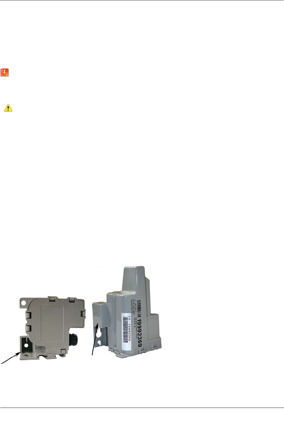
Required Tools and Hardware
• Hammer
• 1/2-inch outside diameter rod (you may use either a square or round rod)
• Tape measure
• Rod-driving tool (optional)
• Rod cutting tool
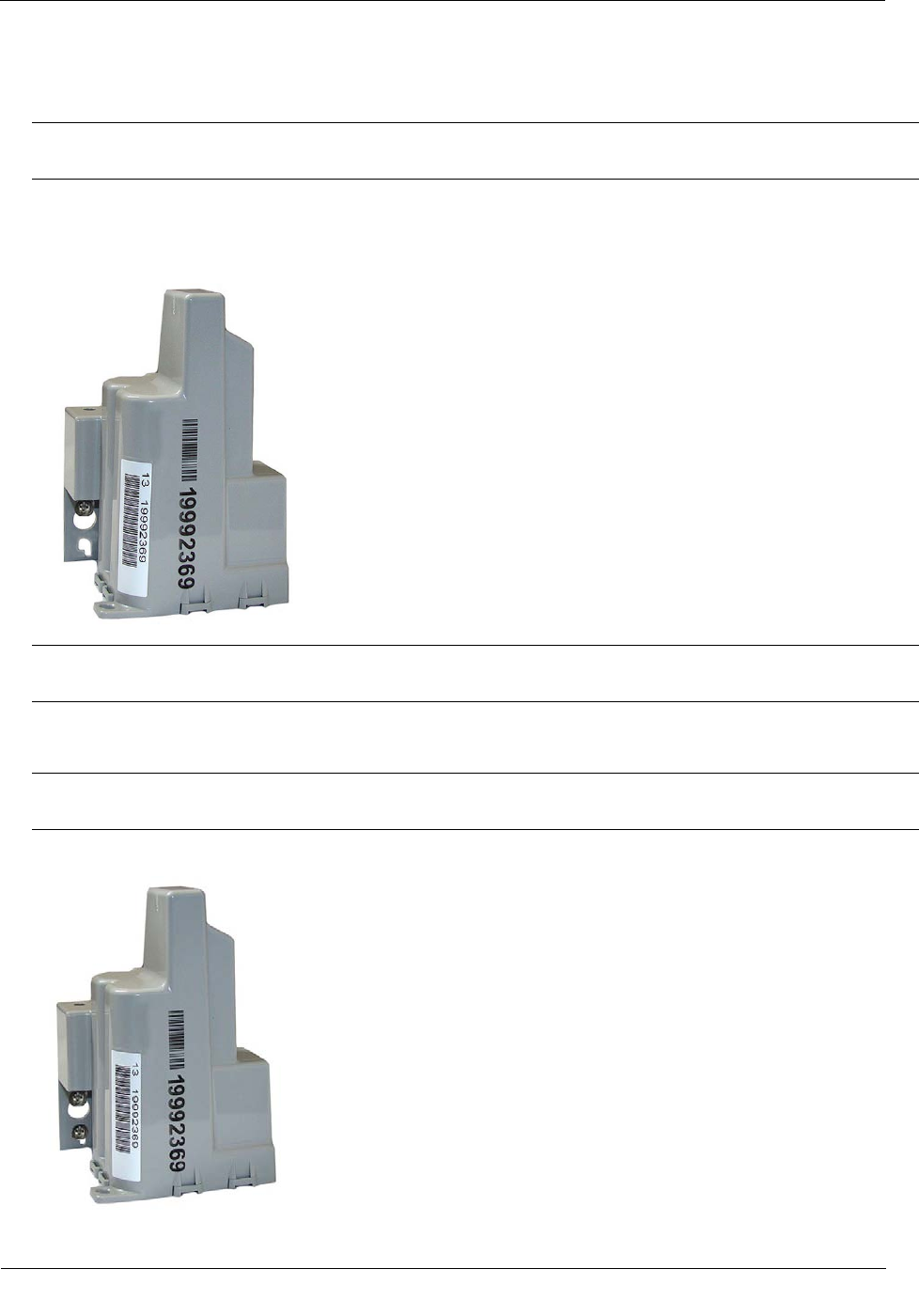
The 1/2-inch diameter rod hole is shown in the following 100W and 100WP ERT module bottom and side
views.
Installing the 100W and 100WP ERT Module
TDC-0909-003 100W and 100WP Datalogging ERT Module Installation Guide 15
Proprietary and Confidential
To install the 100W and 100WP ERT module on a rod
1. Remove the pit lid. Inspect the area to make sure there are no buried cables, pipes, or other obstructions.
2. Measure the pit box depth from the top of the lip (where the lid will rest) to the bottom of the pit. Be sure
to measure the depth at the point where you will drive the rod into the ground.
3. Add 12 inches to the pit box depth measurement taken in step 2. The resulting total represents the
minimum length of rod needed. Soil types and moisture conditions may require longer rod lengths to
ensure the ERT module is well supported and remains vertical.
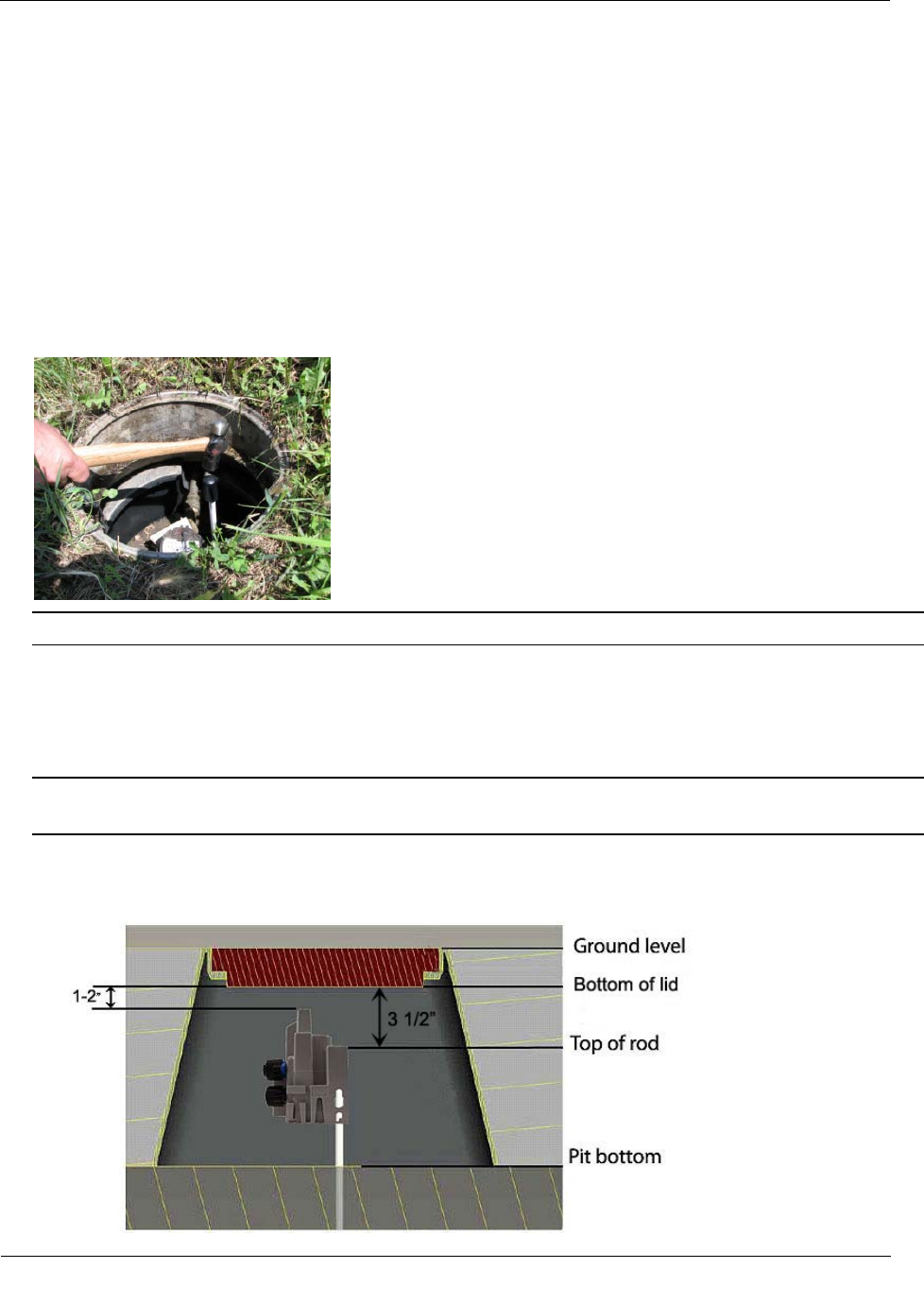
4. Without touching the meter body or adjacent pipes, position the rod as close to the center of the pit as
possible. Drive the rod into the ground. Ensure the rod remains vertical.
Note The rod shown has an end cap to protect the rod while driving it into the ground.
5. Drive the rod into the ground so the top of the rod is approximately 3-1/2 inches below the bottom of the
pit lid.
• If you cannot drive the rod in enough to equal the necessary spacing, cut the remaining rod length to
the proper height using an abrasive cut-off tool.
Caution Cutting fiberglass creates dust particles. Practice proper safety precautions when using cut-off
tools to prevent exposure to fiberglass dust particles.
• If the rod is the correct depth but remains loose in the soil, replace the rod with a longer version.
Installing the 100W and 100WP ERT Module
TDC-0909-003 100W and 100WP Datalogging ERT Module Installation Guide 16
Proprietary and Confidential
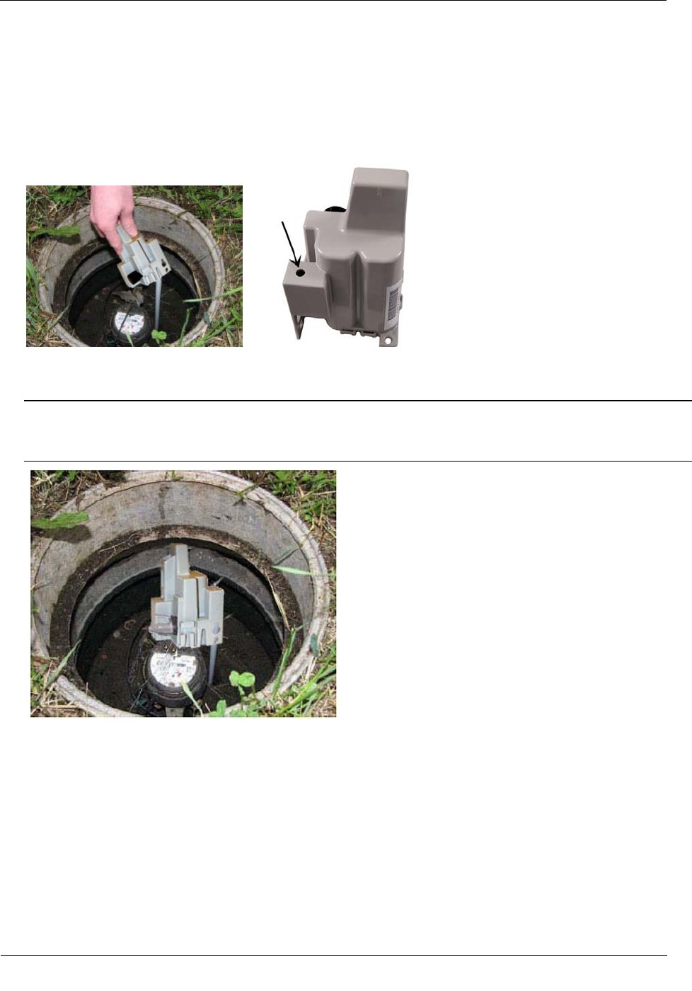
6. The top of the rod must be 3-1/2 inches below the bottom of the lid. Place the ERT module on the rod.
Completely insert the rod into the ERT module's rod mount hole. Do not force the ERT module onto the
rod. If the ERT module does not slide freely on the rod, remove the ERT module and examine the ERT
module rod hole and rod for burrs or obstructions. You may secure the ERT module to the rod with a self-
drilling screw through the hole in the top of the ERT module's rod mount cavity. The screw mounting hole
is shown in the following product image.
7. Installation is complete when the ERT module is perpendicular to the underside of the lid. The ERT
module must not contact the pit structure or lid.
Caution Verify the pit lid does not touch the ERT module when the lid is replaced. There must be a 1 to
2-inch space between the top of the ERT module and the bottom of the pit lid. If the ERT module is
installed too high, too low, or is touching any of the surrounding surfaces, adjust as necessary.
Installing the 100W and 100WP ERT Module
TDC-0909-003 100W and 100WP Datalogging ERT Module Installation Guide 17
Proprietary and Confidential
Wall Mount Installation
Select a flat vertical mounting surface. Install the ERT module in an upright position. Locate the ERT module
as high as possible. To mount the ERT module to the wall in a water pit box, select a mounting location on the
inside of the pit box and try to maintain a distance of one to two inches from the bottom of the pit box lid.
Caution Observe the following guidelines for mounting the ERT module using the wall mount
procedure:
• ERT module positioning other than upright could negatively affect radio
performance and battery life.
• Do not use gel connectors in pit environments.
• Use only Itron-approved splice kits or inline connectors.
The ERT module works accurately with Itron-approved cable type and lengths up to 300 feet.
Required Tools and Hardware
Itron 100W Shelf Mount Kit
To install the 100W and 100WP ERT module using the wall mount procedure
1. Select a vertical surface in the pit box or on a wall (for example, an ERT module mounted in a basement).
2. Position the ERT module vertically so the top of the ERT module is between 1 and 2-inches below the
bottom of the lid.
3. Mark the location of the top mounting hole.
4. Drill a pilot hole in the pit box wall. Follow the screw manufacturer's recommendation for the pilot hole
size.
Installing the 100W and 100WP ERT Module
TDC-0909-003 100W and 100WP Datalogging ERT Module Installation Guide 18
Proprietary and Confidential
5. For concrete-type pit boxes, it may be necessary to use a screw anchor. Choose an anchor appropriate for
a #10 pan head screw.
Caution Do not over-tighten the mounting screws. Over-tightening the mounting screws may break the
ERT module mounting tabs.
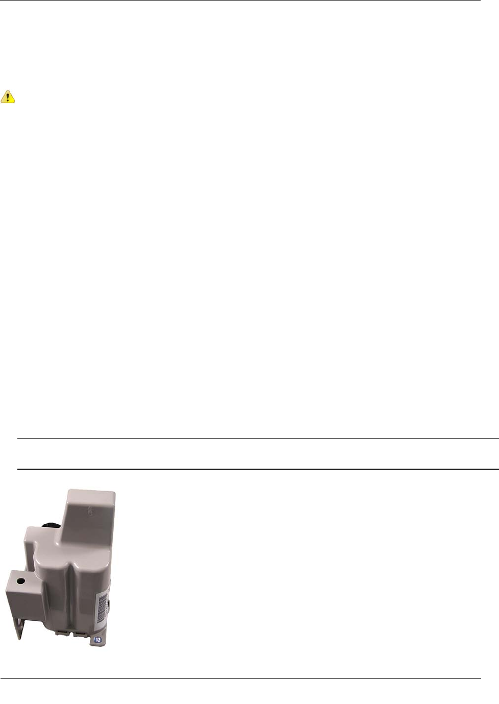
6. Start a screw into the pilot hole. Using the top hole of the ERT module, set the ERT module over the
screw head and slide it down so the screw is now at the top of the notch (as shown). Carefully tighten the
screw until snug. Over-tightening the mounting screw could crack the ERT module housing.
Note If mounting requires a screw anchor, mark the location of the bottom anchor and remove the ERT
module. Drill the required mounting hole, insert the anchor, and re-attach the ERT module.
7. Holding the ERT module in the upright position, drill the second pilot hole. Use the bottom mounting hole
as a template.
Caution Any ERT module position other than upright may negatively affect radio performance and
battery life.
8. Screw the bottom screw into the pilot hole until snug. Do not over-tighten the mounting screw.
Installing the 100W and 100WP ERT Module
TDC-0909-003 100W and 100WP Datalogging ERT Module Installation Guide 19
Proprietary and Confidential
Base Mount Installation
The ERT module may be mounted to a flat surface using the base tab.
Caution Observe the following guidelines for mounting the ERT module using the wall mount
procedure:
• ERT module positioning other than upright could negatively affect radio
performance and battery life.
• Use only Itron-approved splice kits or inline connectors.
Required Base Mounting Tools and Hardware
• Drill and drill bits appropriate for mounting location material.
• Common hand tools for the selected fastening method.
• Mounting screws: #10 size pan head screws appropriate for the wall or pit box material.
To install the 100W and 100WP ERT module using the base mount procedure
1. Select a flat surface.
2. Position the ERT module vertically.
3. Mark the mounting-hole location.
4. Drill a pilot hole in the mounting location material. Follow the screw manufacturer's recommendation for
the pilot hole size.
5. Position the ERT module and insert a #10 pan head screw in the base mounting tab. Carefully tighten the
mounting screw until the ERT module is secure.
Caution Do not over-tighten the mounting screws. Over-tightening the mounting screws may break the
ERT module mounting tabs.
Installing the 100W and 100WP ERT Module
TDC-0909-003 100W and 100WP Datalogging ERT Module Installation Guide 20
Proprietary and Confidential
Shelf Mount Installation
This section describes 100W and 100WP ERT module installation using a shelf mount adapter to mount the
ERT module in a pit lid slot.
Caution Observe the following guidelines for mounting the ERT module using the shelf mount
procedure:
• ERT module positioning other than upright could negatively affect radio
performance and battery life.
• Use only Itron-approved splice kits or inline connectors.
The pit lid and slot must have the correct dimensions for the ERT module assembly to fit
properly.
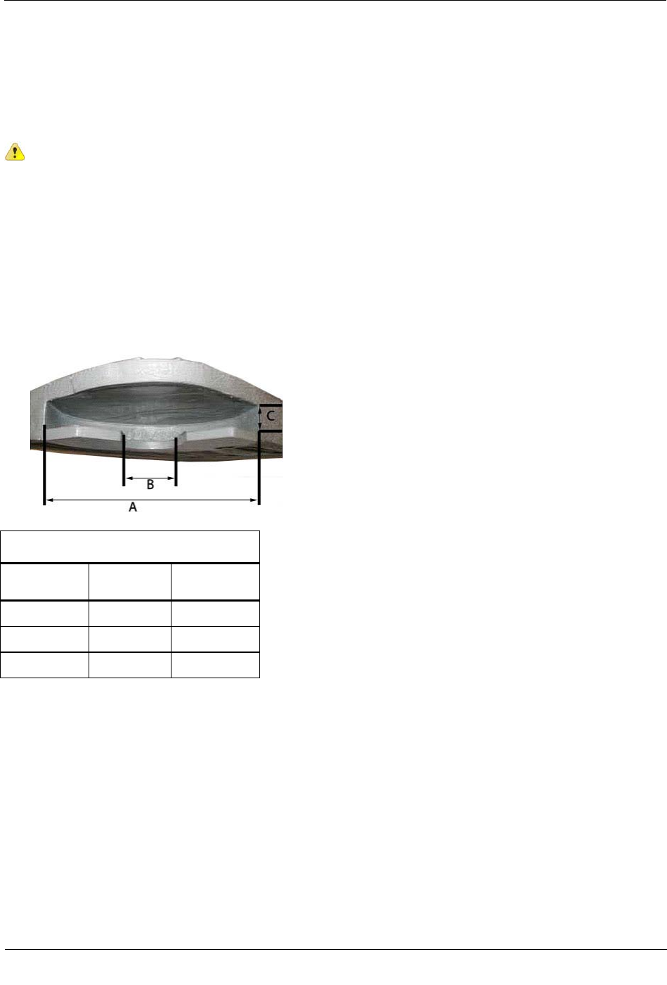
The following illustration and the accompanying table give pit lid slot dimensions for the shelf mount
installation method.
Pit Lid Slot Dimensions
Dimension Minimum
(inches)
Maximum
(inches)
A 6 3/4 N/A
B 2 5 3/4
C 3/4 1
Required Tools and Hardware
Itron 100W Shelf Mount Kit
Installing the 100W and 100WP ERT Module
TDC-0909-003 100W and 100WP Datalogging ERT Module Installation Guide 21
Proprietary and Confidential
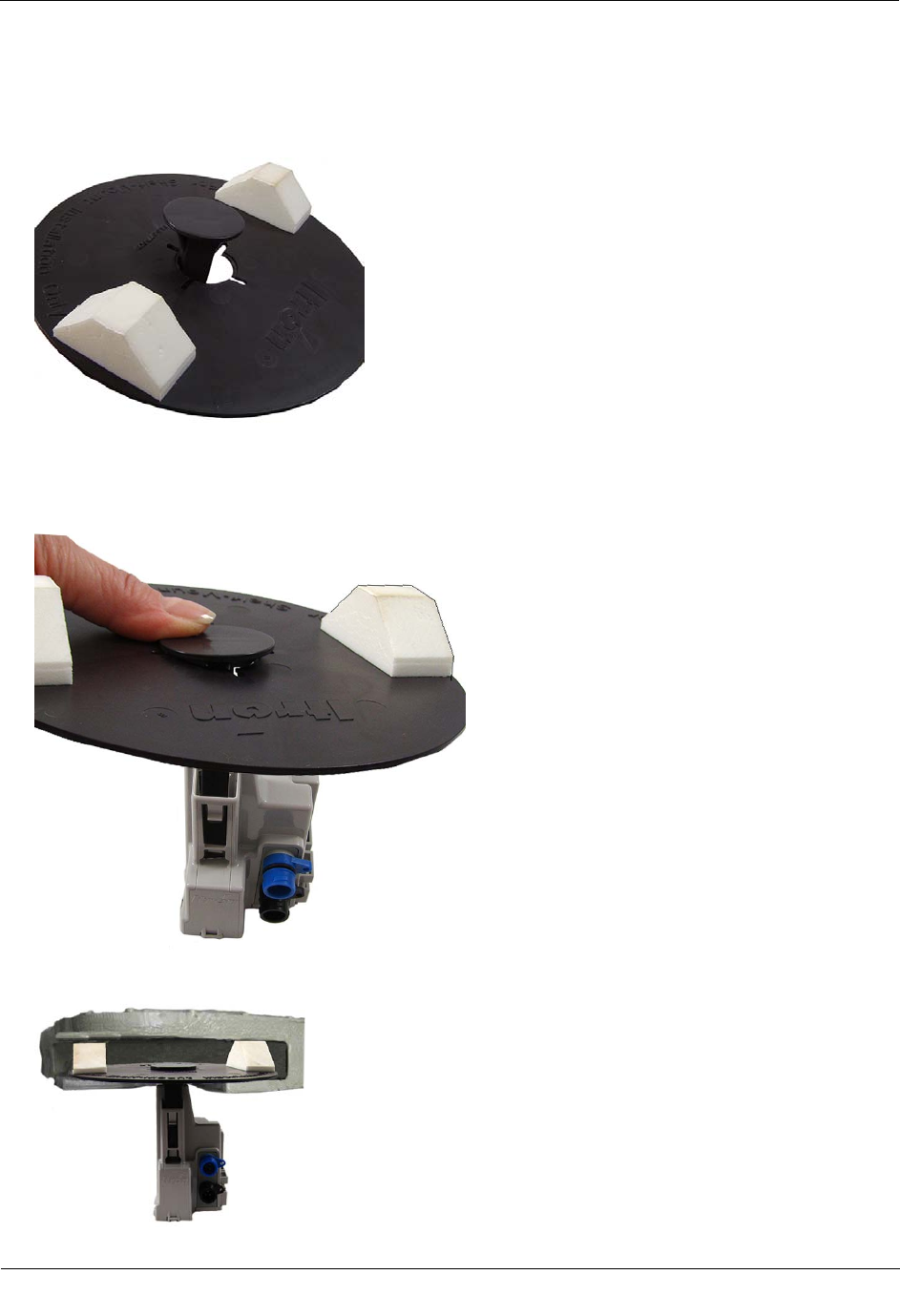
To install using the shelf mount adapter
1. With the foam spacers facing up, insert the shelf mount adapter into the opening in the disk.
2. Push the adapter into the opening gently until the adapter snaps into place. Insert the shelf mount adapter
into the ERT module antenna slot pushing firmly with your thumb until the adapter tab locks into place in
the ERT module antenna slot opening.
3. Slide the adapter assembly into the pit lid with the foam spacers positioned on each side of the pit lid slot.
Installing the 100W and 100WP ERT Module
TDC-0909-003 100W and 100WP Datalogging ERT Module Installation Guide 22
Proprietary and Confidential
Correct position for foam spacers
Caution Do not install the adapter assembly in a manner that provides little or no support under
disk's edge.
Incorrect mounting position for foam spacers.
4. The installed ERT module position must be vertical and upright when the lid is replaced on the pit.
Caution When placing the pit lid on to the pit box after the shelf mount adapter installation, use care to
avoid pinching or damaging the ERT module to meter cable. Any ERT module position other than upright
may negatively affect radio performance and battery life.
Through Lid Mount
This section provides instructions to mount the 100W and 100WP ERT module in a pit lid with a drilled,
round 1-3/4-inch, 1-7/8-inch, or 2-inch hole.
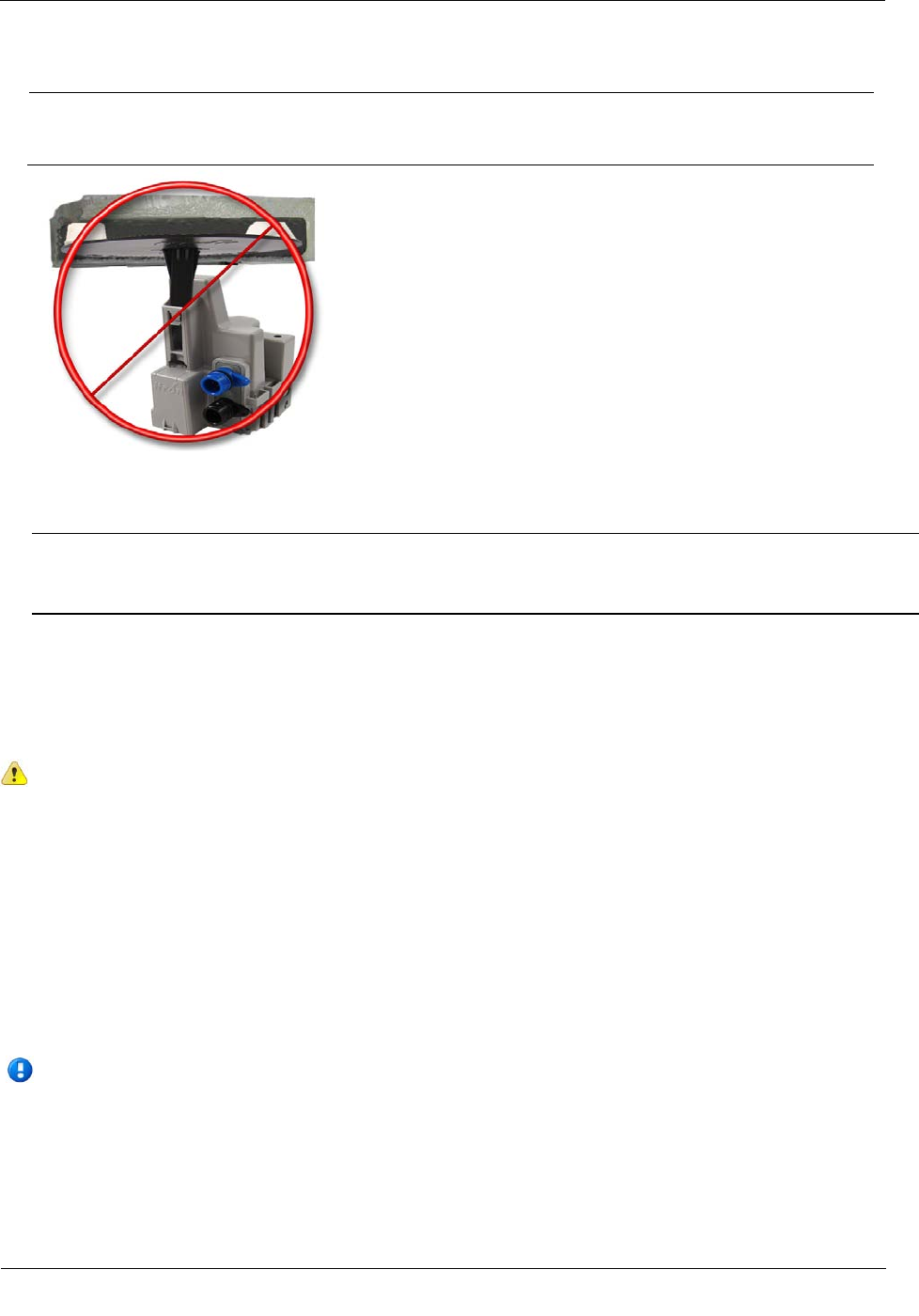
Caution Some pit lids have a molded, recessed cavity that allows Itron 40W-1, 50W-1, and
50W-2 ERT modules to sit flush with the top surface of the lid. However, the dome of the
ERT module retainer for the 100W or 100WP ERT module has a smaller diameter and does
not fill the pit lid cavity. This can cause the cavity to become a trip hazard. Itron does not
recommend using this type of pit lid with 100W and 100WP ERT modules.
Required Tools and Hardware
This mounting method requires the Pit Lid Mounting Kit. Refer to the 100W Installation Methods Overview
(PUB-1300-004) for guidance on which kit to install for different pit lid material and traffic conditions.
Pit Lid Mounting Kit (CFG-1300-004)
Note The Pit Lid Mounting Kit is not intended for applications involving vehicular traffic. Use the
Remote Antenna Kit in incidental traffic areas (such as residential environments).
Installing the 100W and 100WP ERT Module
TDC-0909-003 100W and 100WP Datalogging ERT Module Installation Guide 23
Proprietary and Confidential
To install in lids with holes using the Pit Lid Mounting Kit (CFG-0771-011)
This section provides the instructions to install the 100W and 100WP ERT module in a pit lid with a hole
using the Pit Lid Mounting Kit (CFG-1300-004).
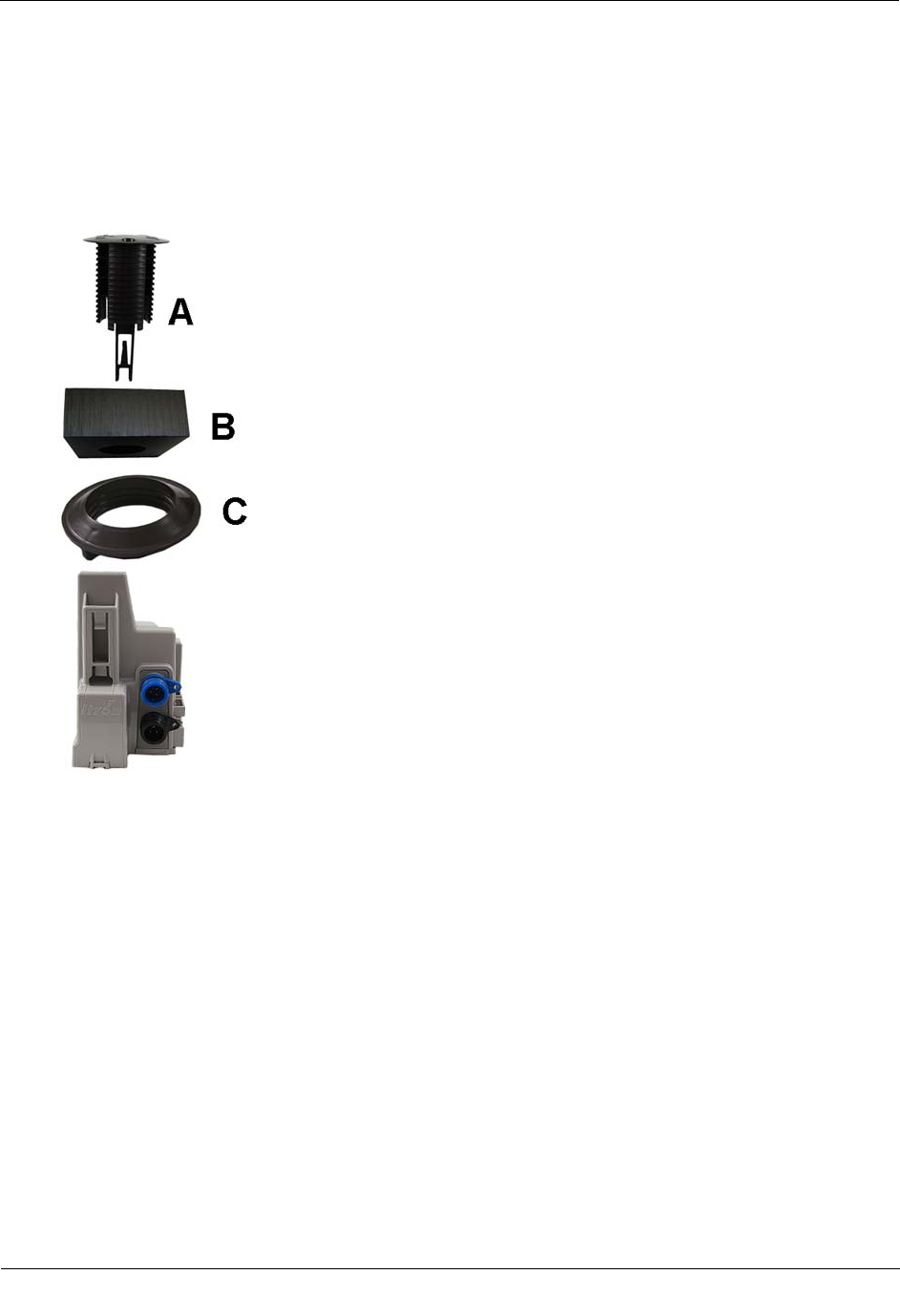
1. Verify you have the following items to complete the installation.
A Retainer clip
B Pit lid with a pre-drilled hole
(simulated pit lid material shown)
C Retainer clip collar
D 100W and 100WP ERT module
Installing the 100W and 100WP ERT Module
TDC-0909-003 100W and 100WP Datalogging ERT Module Installation Guide 24
Proprietary and Confidential
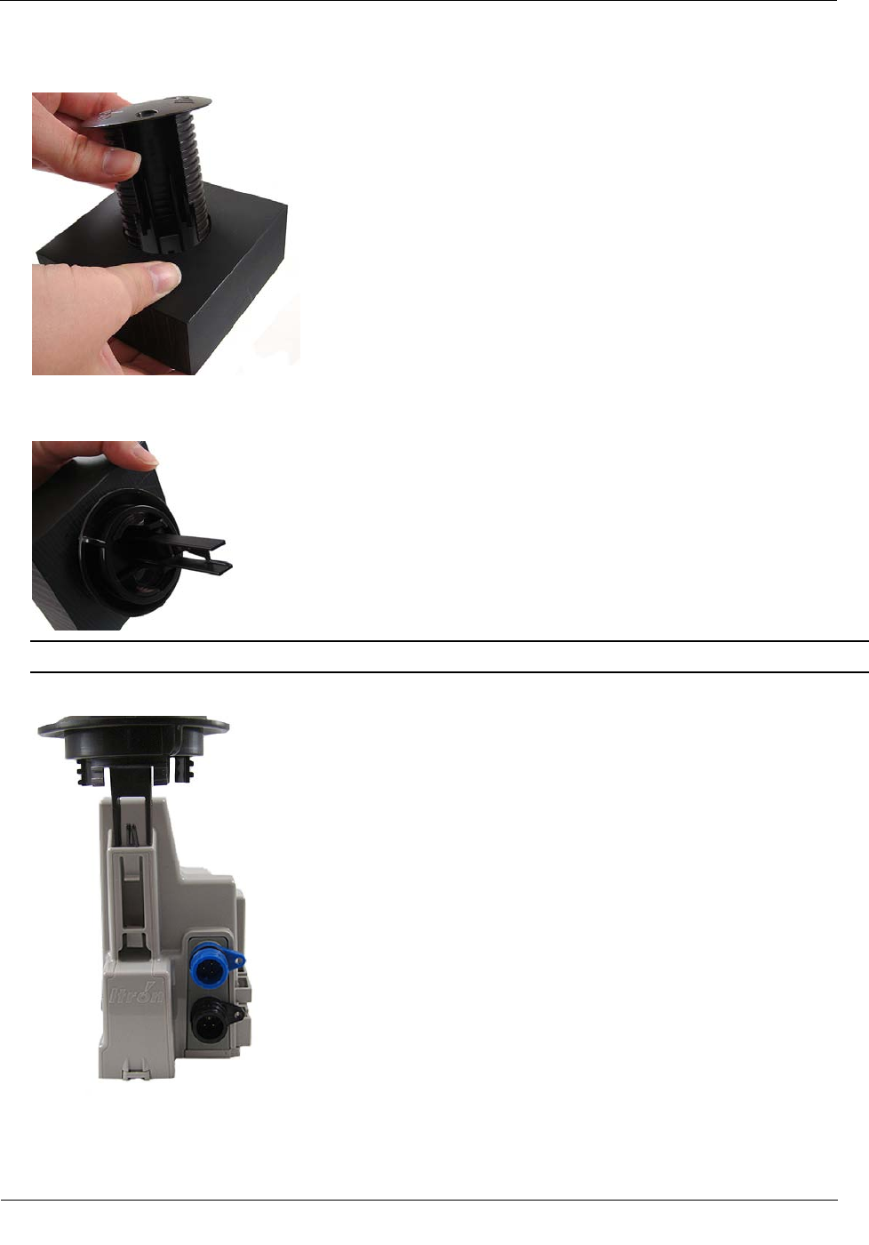
2. Insert the retainer clip into the pit lid hole with the convex surface on the top of the pit lid.
3. From the bottom side of the lid, screw on the threaded retainer clip collar until the beveled top rests
against the pit lid.
Note Ensure the beveled edge of the clip collar is toward the top of the pit lid.
4. Align and insert the retainer clip tab into the retainer clip receptacle on the ERT module housing.
Installing the 100W and 100WP ERT Module
TDC-0909-003 100W and 100WP Datalogging ERT Module Installation Guide 25
Proprietary and Confidential
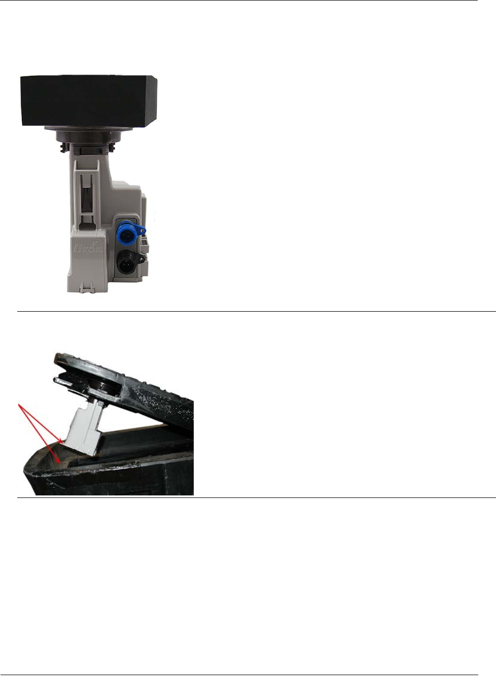
5. Verify the clip locks into place in the housing.
Caution Carefully align the ERT module through lid assembly. If the assembly is improperly aligned, the
pit lid may not close.
Pit Lid Mounting Kit installation is complete.
Installing in a New Lid
This section describes installation of the 100W and 100WP ERT module in a pit lid without a drilled hole.
To install the 100W in new lids
1. Select a hole location with enough clearance on the bottom side of the lid to attach the threaded clip collar.
2. Drill a 1-3/4 inch hole in the lid.

Installing the 100W and 100WP ERT Module
TDC-0909-003 100W and 100WP Datalogging ERT Module Installation Guide 26
Proprietary and Confidential
3. See To install in lids with holes using the Pit Lid Mounting Kit on page 23 to complete installation in a
new lid.
Optional Leak Sensor Installation
Leak Sensors (LS) analyze water flow sound patterns to detect new, evolving, and pre-existing leaks. LS
analysis data is uploaded to mlogonline™ Network Leak Monitoring for data analysis and accessed through a
secure Internet portal unique to your utility. This section describes installation of the Leak Sensor (LS) in a
100W and 100WP ERT module system.
The ERT module stores 20 days of Leak Sensor data. On the 21st day, the ERT module begins to write over
stored data in a first in, first out manner.
The ERT module automatically detects the presence of connected Leak Sensors. The ERT module will
automatically detect the Leak Sensor within 22.5 minutes and begin reading Leak Sensor data. To
immediately detect the Leak Sensor and begin reading data, perform a Check ERT with a handheld computer
running FDM software.
The LS is used in conjunction with both indoor (basement) and outdoor (mounting on the exterior of the
house) 100W and 100WP ERT module installations. LS devices are mounted on a water service pipe or meter
insetter (meter horn) and connect to the Leak Sensor connector on the ERT module as described in To connect
the Leak Sensor to the 100W and 100WP ERT module on page 27. The mounting bracket shipped with the
Leak Sensor accommodates an (up to) 1-1/2-inch OD pipe. An optional mounting bracket is available for pipe
sizes (up to 2 1/2-inch OD).
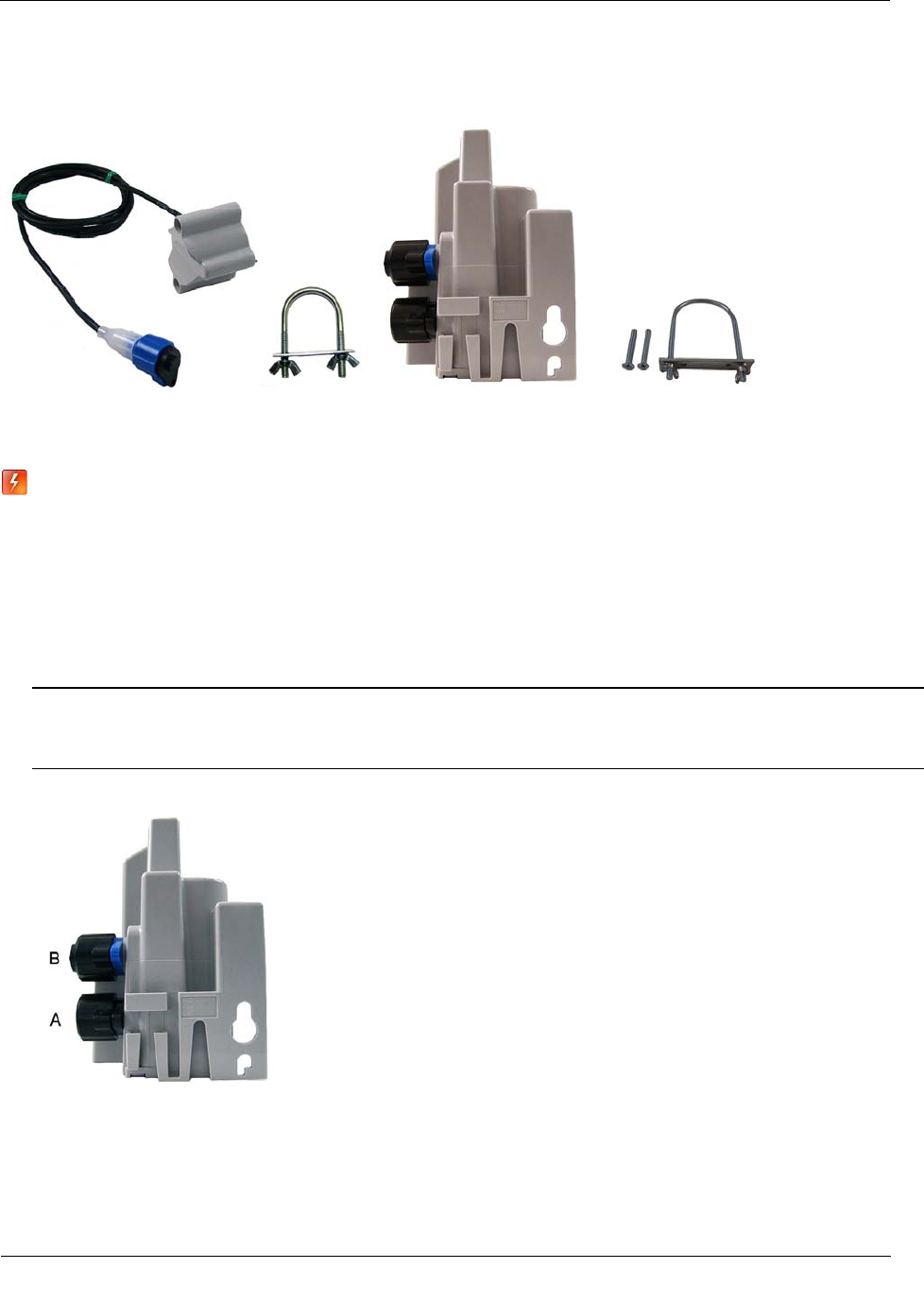
Required Equipment
Equipment
Itron Part Number
Description
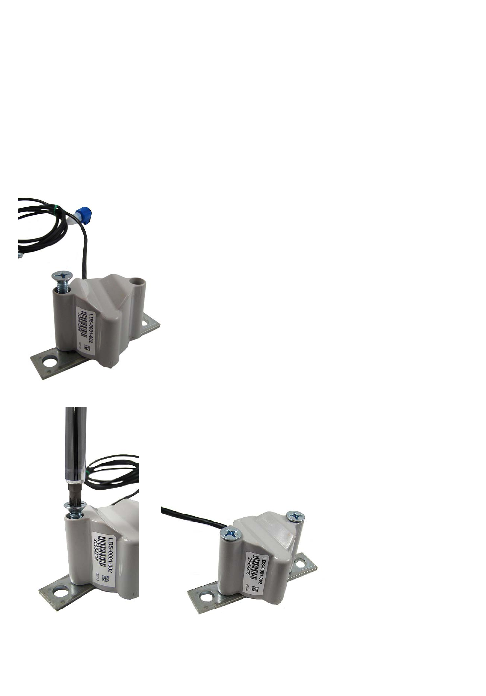
Leak Sensor LDS-0001-002 LS with inline connector, environmental connector cap; 5-foot
cable, and mounting bolt (fits up to 1 1/2-inch OD pipe).
Optional mounting bracket CFG-0349-002 Mounting bolt fits up to 2 1/2-inch OD pipe.
100W ERT module
100WP ERT module
ERW-1300-102
ERW-1300-108
Dual port ERT module for LS and environmental connector caps.
25-foot extension cable CFG-0349-101 25-foot cable with coordinating connectors (LS blue connector,
register black connector).
100W LS environmental replacement
cap MSC-0019-005 Protects Leak Sensor connector when the Leak Sensor is not
connected to the 100W ERT module.
Itron Security Seal MSC-0018-001 Indicates module tampering and ensures the protective cover stays
intact.
Installing the 100W and 100WP ERT Module
TDC-0909-003 100W and 100WP Datalogging ERT Module Installation Guide 27
Proprietary and Confidential
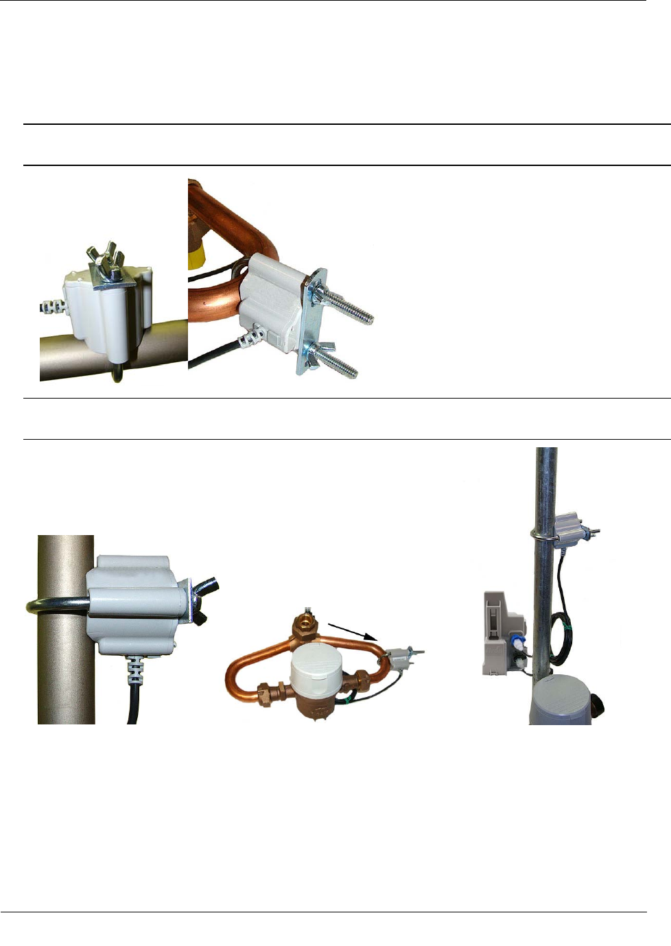
Leak Sensor Mounting 100W/100WP ERT Optional mounting bracket
bracket
Warning When the 100W or 100WP is installed but the Leak Sensor is not attached, you must
protect the blue Leak Sensor port with the environmental cap (MSC-0019-005). If you remove the
Leak Sensor from the ERT module, the environmental cap must be replaced to protect the
connector.
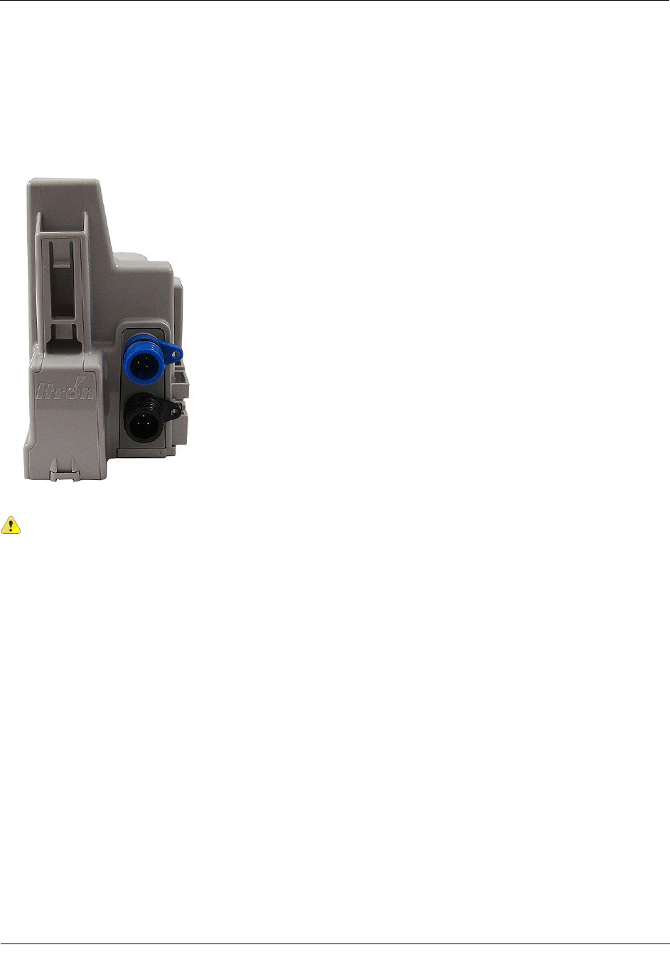
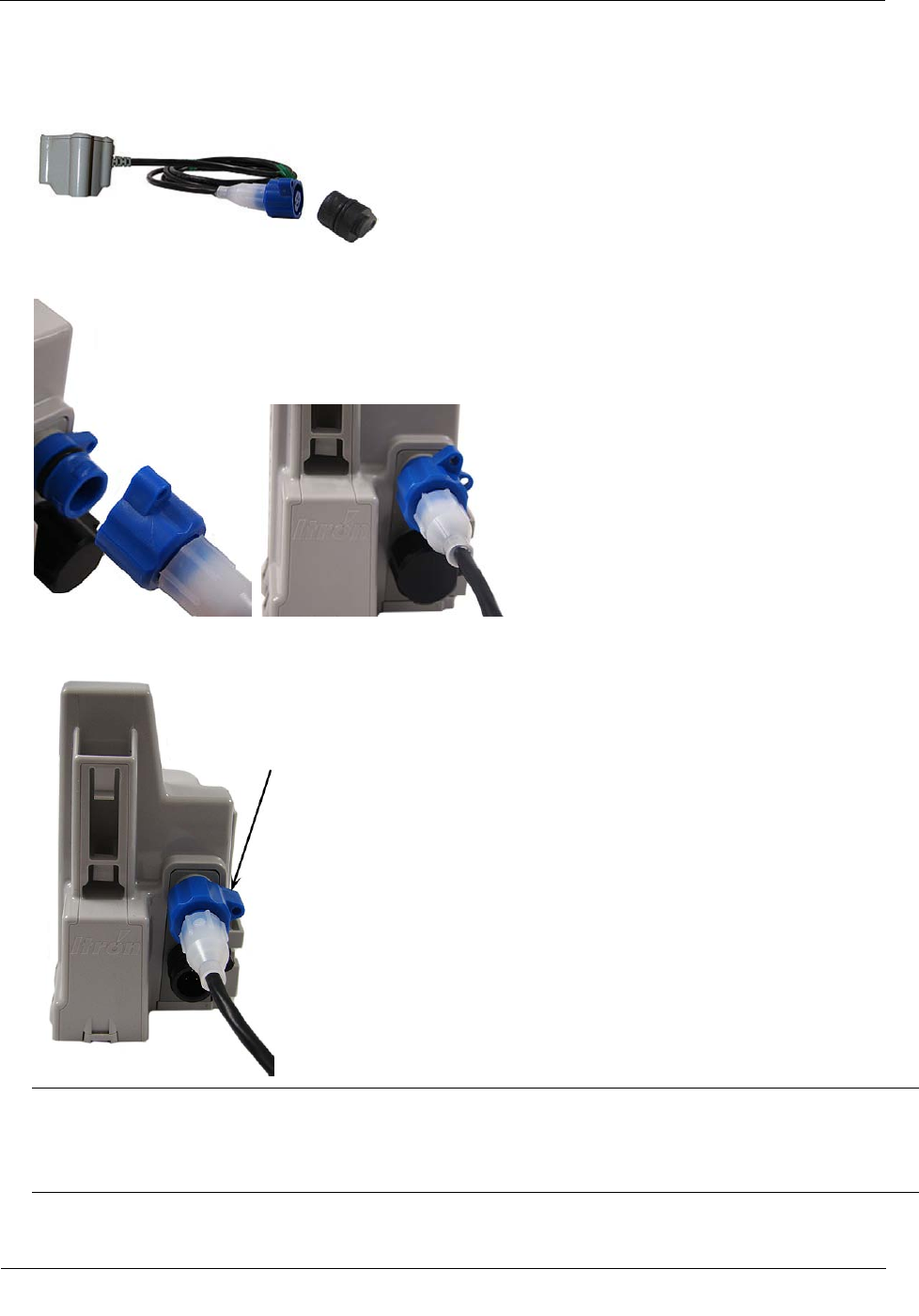
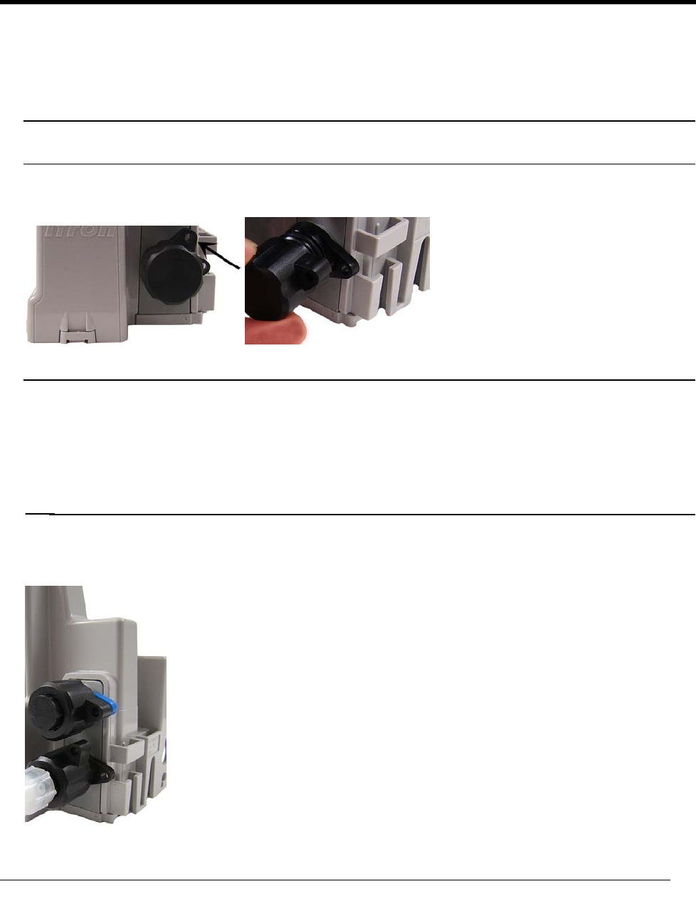
To connect the Leak Sensor to the 100W and 100WP ERT module
Caution Verify you have the correct 100W or 100WP ERT module. Leak Sensors must mount to Port B
(top port) of the ERT module. Connecting the LS to Port A (bottom port) will cause electrical damage to
the LS and ERT module.
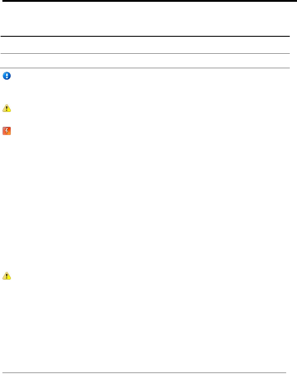
1. Remove the environmental cap from the ERT module's blue connector (B).
B. Blue connector: Leak Sensor connection
A. Black connector: register connection
Installing the 100W and 100WP ERT Module
TDC-0909-003 100W and 100WP Datalogging ERT Module Installation Guide 28
Proprietary and Confidential
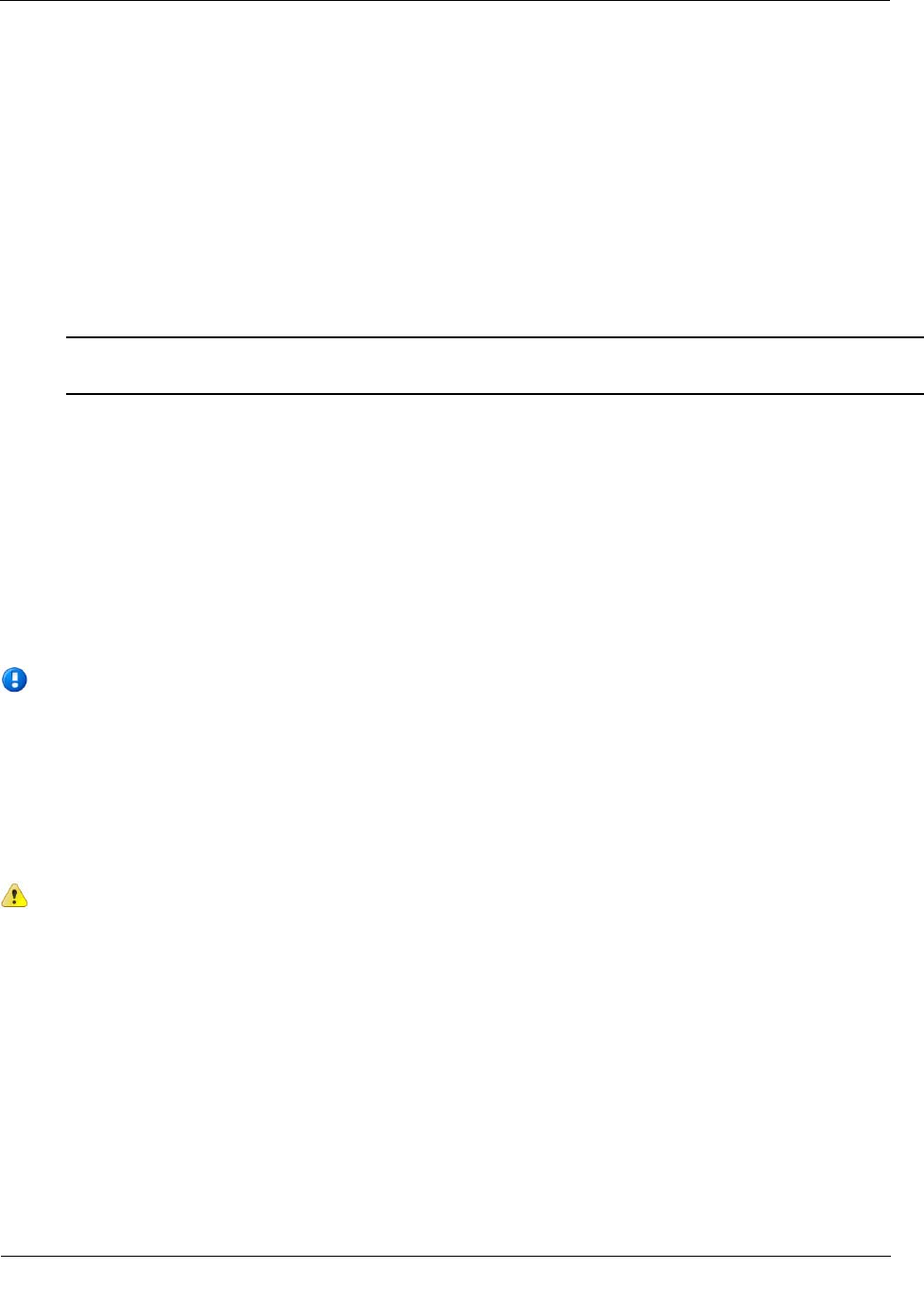
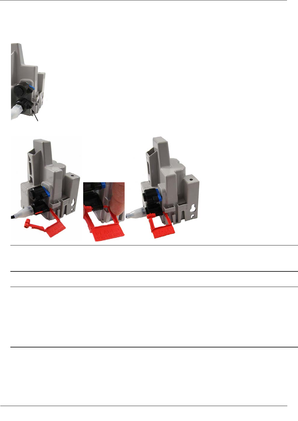
2. Remove the environmental cap from the Leak Sensor connector. Verify the connectors (the ERT module's
LS connector and the Leak Sensor connector) are clean and dry.
3. Align the Leak Sensor connector with the ERT module's blue connector and insert.
4. Rotate the connector locking ring until the security holes align.
Caution Do not force the connector ends together. While holding the LS connector, engage the ERT
module's connector by rotating the locking ring until both connectors securely connect. Twist only the
connector locking ring, not the body of the connector. Twisting the connector body could damage the
connector's pins.
Installing the 100W and 100WP ERT Module
TDC-0909-003 100W and 100WP Datalogging ERT Module Installation Guide 29
Proprietary and Confidential
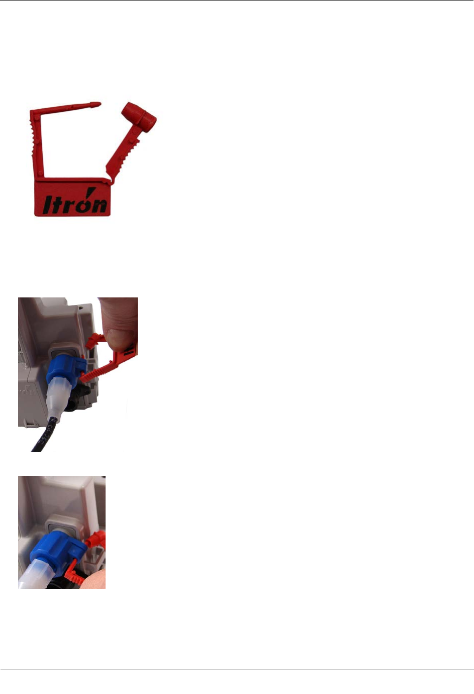
Required Materials
Itron Security Seal (MSC-0018-001)
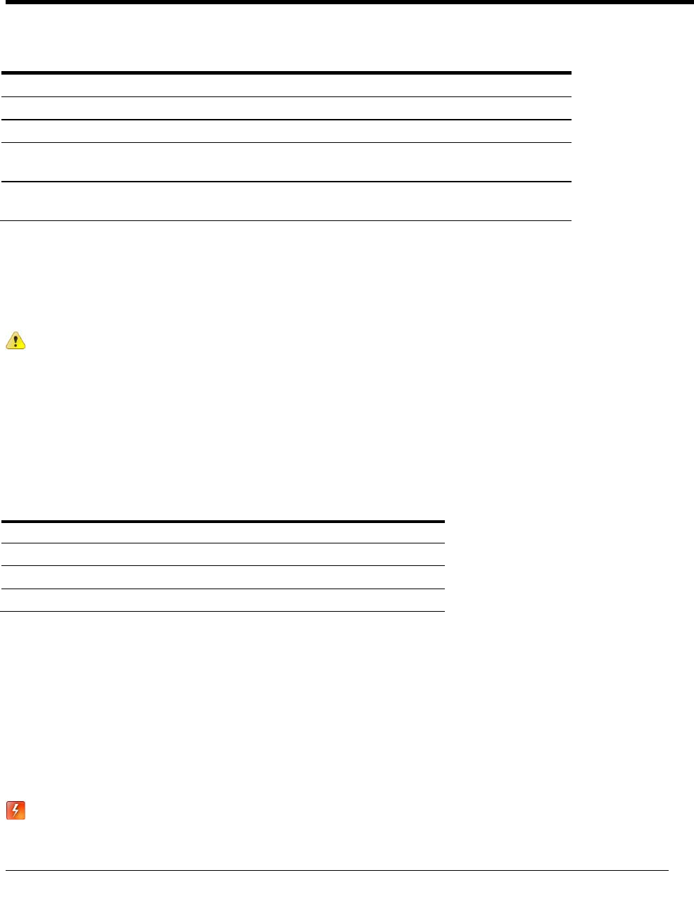
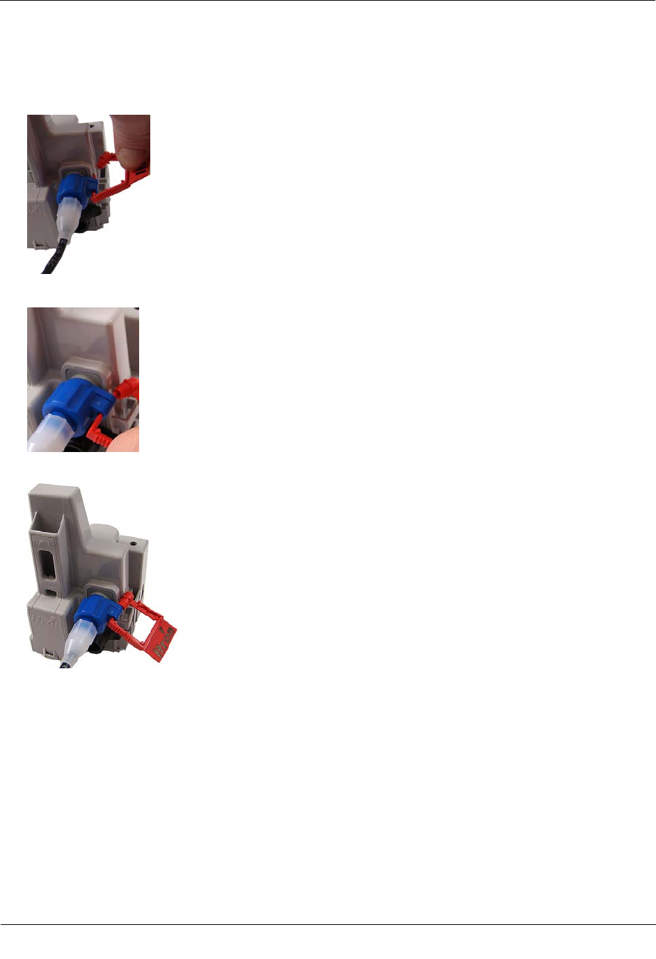
To attach an Itron Security Seal through the connector security hole
1. Insert the pointed end of the security seal through the inline connector and the ERT module connector
security holes.
2. Insert the pointed end of the security seal into the capped end and push until the seal locks.
This completes the ERT module and Leak Sensor connections.
Installing the 100W and 100WP ERT Module
TDC-0909-003 100W and 100WP Datalogging ERT Module Installation Guide 30
Proprietary and Confidential
Pipe Preparation
Clean any dust or dirt from the pipe to facilitate direct contact with the LS surface.
To install the Leak Sensor on a pipe or meter insetter
1. Select a Leak Sensor mounting location within 5-feet of the ERT module. Mount the sensor on the water
input side of the meter.
Caution Mount the Leak Sensor on the water input side of the meter. Failure to follow this mounting
requirement could result in errors in the leak detection data. Installation requires Itron mounting hardware.
Repair costs and service charges relating to the use on non-compliant mounting hardware will be charged
to the customer. Contract Itron Support for more information.
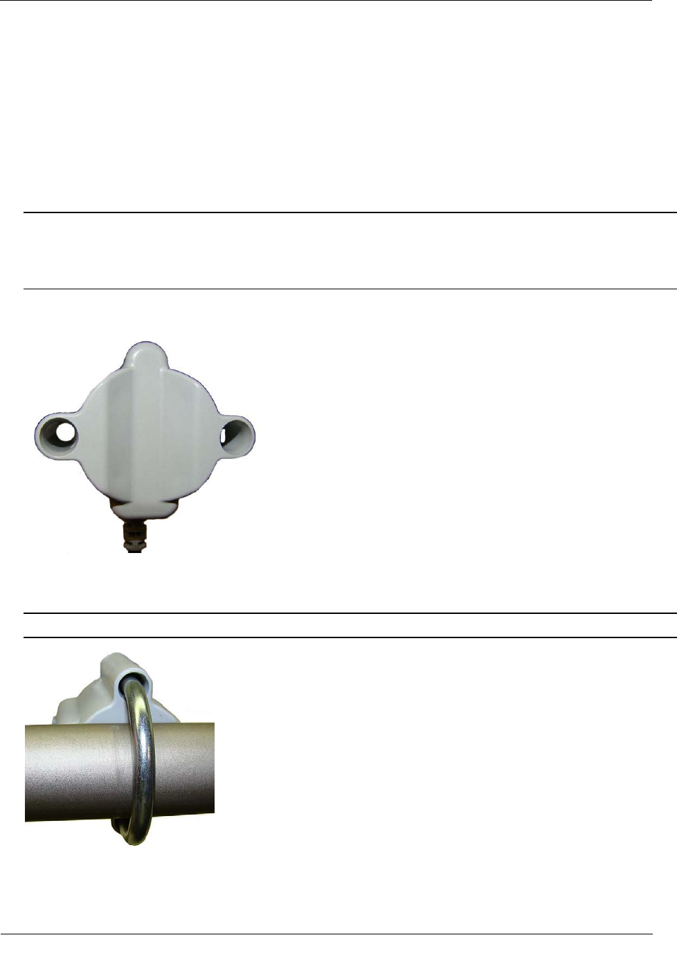
2. Verify the pipe’s mounting surface is free from dirt and debris. Place the curved surface of the LS against
the pipe.
3. Insert the mounting U-bolt over the pipe and into the LS mounting holes.
Caution Do not mount the Leak Sensor on a pipe coupler, joint, or nut.
Installing the 100W and 100WP ERT Module
TDC-0909-003 100W and 100WP Datalogging ERT Module Installation Guide 31
Proprietary and Confidential
4. Insert the mounting plate over the U-bolt's threaded screw ends. Attach the two wing nuts over the clamp
screw ends and tighten the wing nuts until snug (to a minimum of 5-inch pounds) to prevent device
rotation on the pipe. After you tighten the second wing nut, check the Leak Sensor to verify the device is
snug. If the sensor moves, tighten the wing nuts until there is no movement.
Caution Do not tighten the Leak Sensor to more than 20 inch-pounds. Over-tightening could damage the
Leak Sensor housing and/or the pipe.
Note Leak Sensor mounting orientation is not critical. Orient the sensor to best accommodate your
installation. The most important installation practice is to mount the sensor securely to the pipe.
Installing the 100W and 100WP ERT Module
TDC-0909-003 100W and 100WP Datalogging ERT Module Installation Guide 32
Proprietary and Confidential
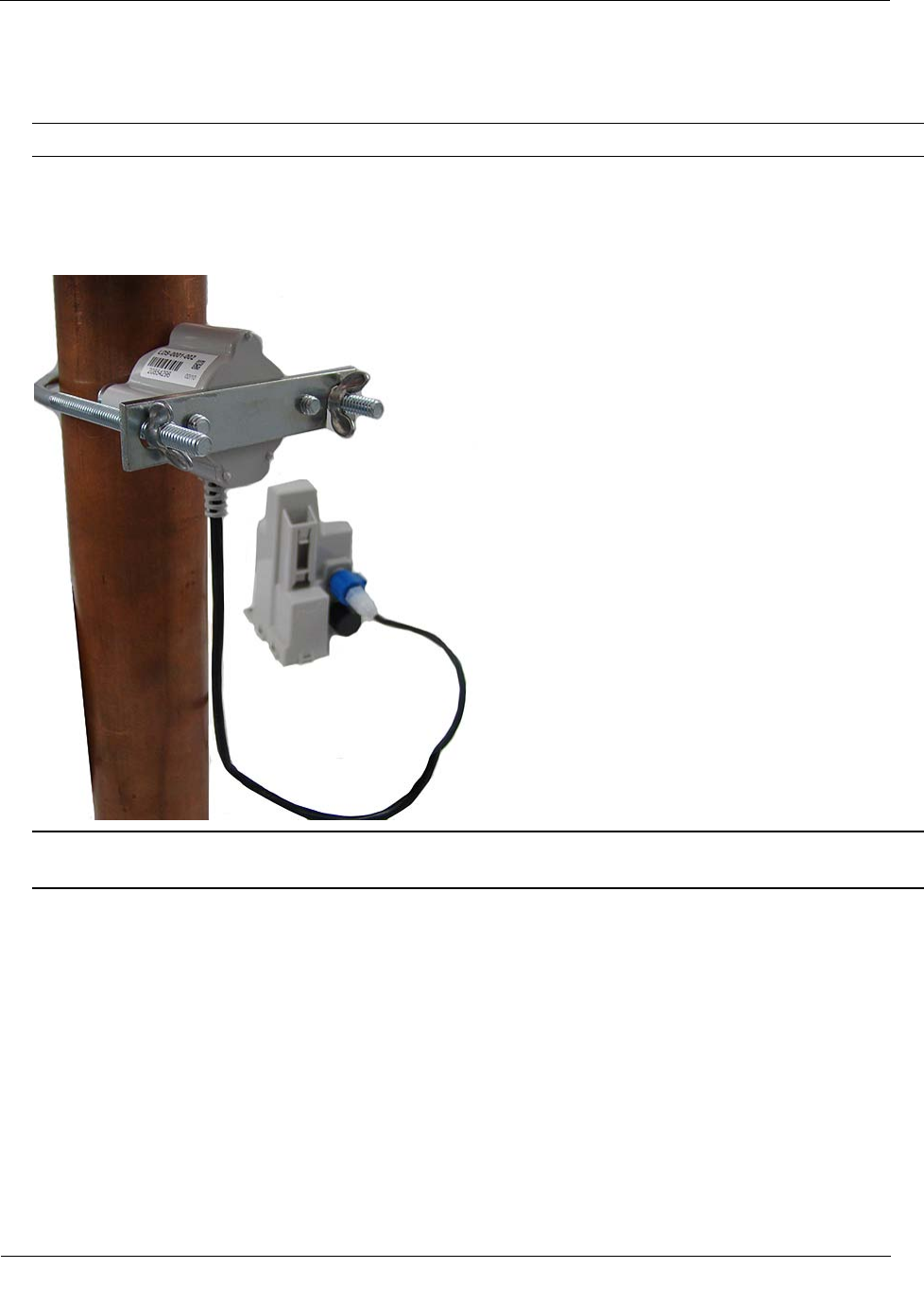
To install the Leak Sensor on a pipe (up to 2 1/2-inch OD)
1. Select a Leak Sensor mounting location within 5 feet of the ERT module.
Note Leak Sensor mounting orientation is not critical. Orient the sensor to best accommodate your
installation. The most important installation practice is to fasten the sensor securely to the pipe.
Caution Mount the Leak Sensor on the water input side of the meter. Failure to follow this mounting
requirement could result in errors in the leak detection data. Installation requires Itron mounting hardware.
Repair costs and service charges relating to the use on non-compliant mounting hardware will be charged
to the customer. Contract Itron Support for more information.
2. Insert the mounting plate screws into the holes on the Leak Sensor's curved surface.
3. Secure the mounting plate to the Leak Sensor.
Installing the 100W and 100WP ERT Module
TDC-0909-003 100W and 100WP Datalogging ERT Module Installation Guide 33
Proprietary and Confidential
4. Verify the pipe’s mounting surface is free from dirt and debris. Place the curved surface of the LS against
the pipe.
Caution Do not mount the Leak Sensor on a pipe coupler, joint, or nut.
5. Insert the U-bolt around the pipe and into the holes in the plate/Leak Sensor assembly. Secure the U-bolt
with the wing nuts. Tighten the wing nuts until snug (to a minimum of 5-inch pounds) to prevent device
rotation on the pipe. After the second wing nut is tightened, check the Leak Sensor to verify the device is
snug. If the sensor moves, tighten the wing nuts until there is no movement.
Caution Do not tighten the Leak Sensor to more than 20 inch-pounds. Over-tightening could damage the
Leak Sensor housing and/or the pipe.

TDC-0909-003 100W and 100WP Datalogging ERT Module Installation Guide 34
Proprietary and Confidential
The 900 MHz remote mount antenna provides increased RF range coverage for the listed mobile applications
where the meters are located deep in a pit boxes.
This section provides antenna mounting instructions through a pit lid and the instructions to connect the
antenna to the ERT module.
Caution Only remote antenna ERT modules can be used with the remote antenna. See the
following table for 100W and 100WP remote antenna ERT models.
100W and 100WP Remote Antenna Models
100W and 100WP ERT Module Description
Itron Part Number
100W Encoder, with Remote Antenna, integral connector ERW-1300-118
100WP Pulser, with Remote Antenna, integral connector ERW-1300-119
Industry Canada Conformity
This radio transmitter (IC:864D-100WB) has been approved by
Industry Canada to operate with the antenna types listed below
with the maximum permissible gain and required antenna
impedance for each antenna type indicated. Antenna types not
included in this list, having a gain greater than the maximum gain
indicated for that type, are strictly prohibited for use with this
device.
Le présent émetteur radio (IC: 864D-100WB) a été approuvé par
Industrie Canada pour fonctionner avec les types d'antenne
énumérés ci-dessous et ayant un gain admissible maximal et
l'impédance requise pour chaque type d'antenne. Les types
d'antenne non inclus dans cette liste, ou dont le gain est supérieur
au gain maximal indiqué, sont strictement interdits pour
l'exploitation de l'émetteur.
Specification
Part number CFG-0900-003
Gain 7.0 dBi
Horizontal beamwidth Omnidirectional
Impedance 50 ohms
Termination Proprietary
C
HAPTER
5
Remote Antenna Installation
Remote Antenna Installation
TDC-0909-003 100W and 100WP Datalogging ERT Module Installation Guide 35
Proprietary and Confidential
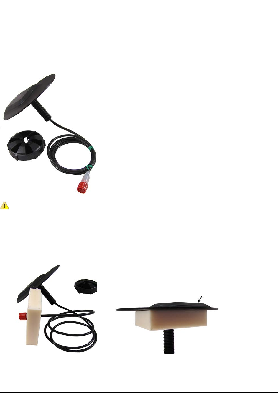
Installing the Remote Antenna
Metal lids on water pit boxes require a through-lid solution for optimal ERT module radio performance. The
remote antenna is designed to fit in a pit lid hole with a diameter of 3/4-inch and lid thicknesses from 1/4-inch
to 1-3/4-inch.
Caution Remove any cable or twist ties from the antenna cable to prevent damage to the ERT
module or antenna.
To install the remote antenna through a pit lid
1. Thread the remote antenna connector and cable through the pit lid hole. Verify the antenna's convex
surface is on the top of the pit lid. (These instructions show a simulated pit lid material.)
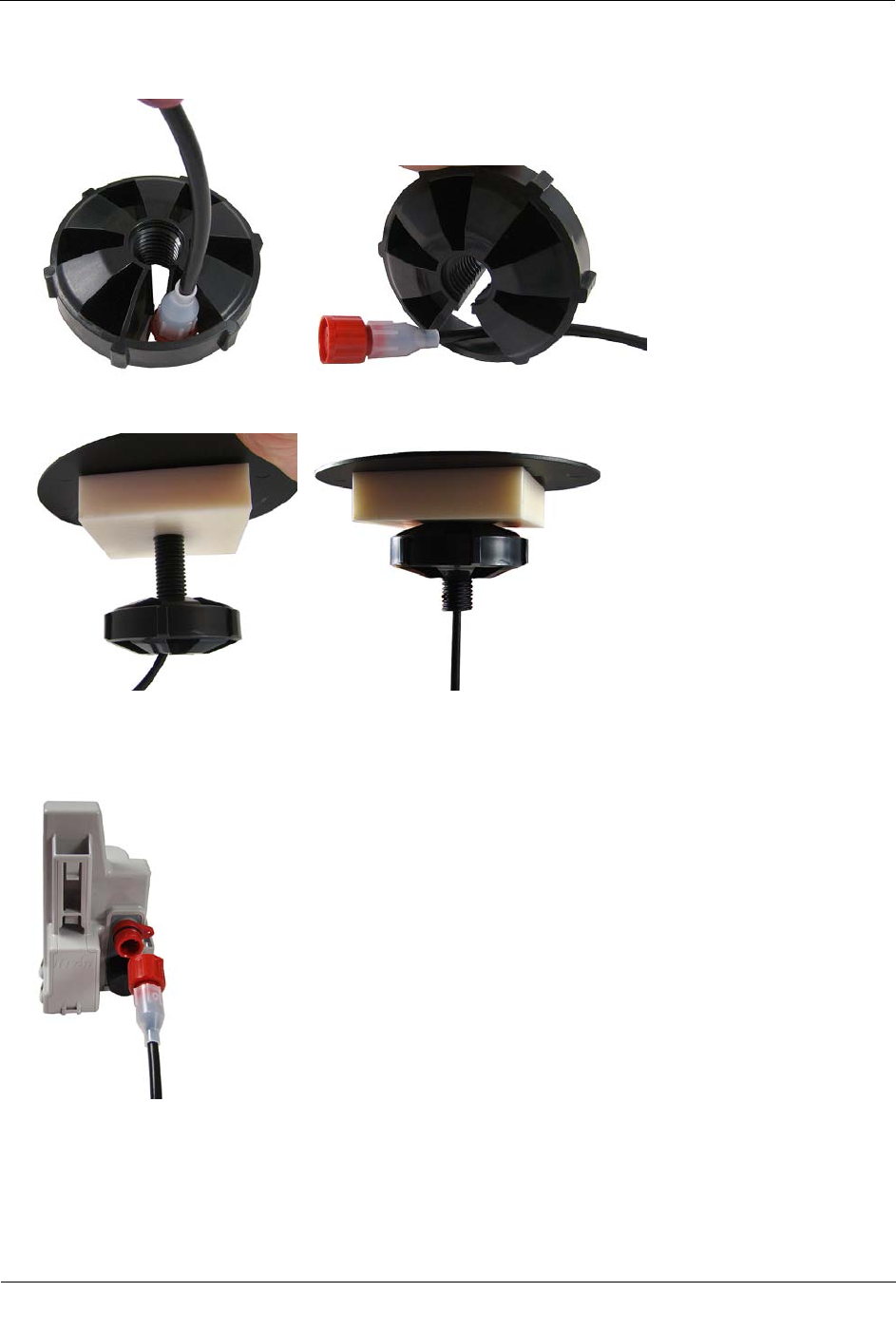
Remote Antenna Installation
TDC-0909-003 100W and 100WP Datalogging ERT Module Installation Guide 36
Proprietary and Confidential
2. Insert the antenna connector through the rectangular opening in the threaded collar.
3. Turn the threaded collar until it is tight against bottom of the pit lid.
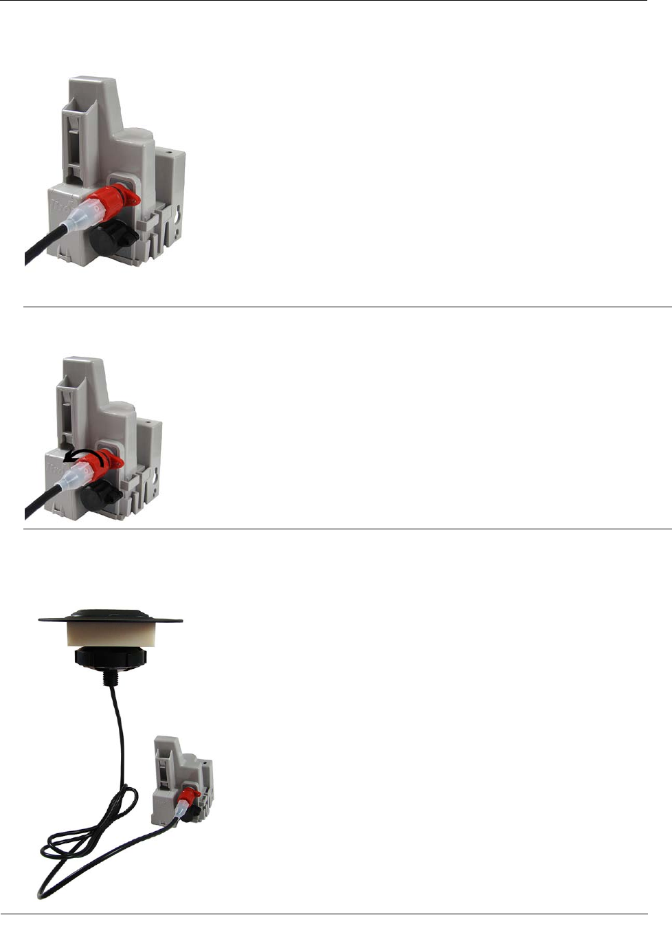
To connect the remote antenna to the ERT module
1. Align the connector pins with the top, red connector on the ERT module.
Remote Antenna Installation
TDC-0909-003 100W and 100WP Datalogging ERT Module Installation Guide 37
Proprietary and Confidential
2. Push in the antenna connector to complete the connection.
3. Turn the connector lock ring to the left to secure the connection.
Caution Turn the connector lock-ring only. Do not twist the completed connection. Twisting the
connection could damage the ERT module or antenna connector pins.
4. Follow the Rod Mount Installation (on page 13) or Wall Mount Installation (on page 17) instructions to
mount the ERT module.
Remote antenna installation is complete.
TDC-0909-003 100W and 100WP Datalogging ERT Module Installation Guide 38
Proprietary and Confidential
This section describes the 100W connections to the water meter register using the inline connector assembly.
Follow the manufacturer's recommended procedure for installing the water meter register on the meter.
To connect the inline connector
Note If an inline connector is not used and the ERT module is already connected to the water meter
register, skip this step.
1. Remove the protective cover from the connector by twisting the two halves in opposite directions. Pull the
halves apart.
Caution Verify the connector halves are clean and dry before assembly.
If any of the following conditions occur, do not install the ERT modules:
• Any of the three pins are damaged or missing.
• The O-ring is missing.
• The cable is cut or nicked.
2. Connect the register cable to the ERT module connector. Holding the connectors by the back shells, rotate
one end to align the keyed slots. Push until snug. Slide the black coupling nut over the O-ring. Make sure
the O-ring stays seated. If the O-ring does not stay seated, disconnect and try again.
A
PPENDIX
A
Using an Inline Connector
Using an Inline Connector
TDC-0909-003 100W and 100WP Datalogging ERT Module Installation Guide 39
Proprietary and Confidential
3. Twist the register cable's black coupling nut to align the two tabs.
4. Install the security seal as shown. Push it until it snaps into place.
Note For future meter or ERT module servicing, break the security seal by pulling the seal apart. The
original protective connector covers can be reused if kept clean and dry. Install a new security seal after
servicing either device. To order more parts, see the Water Endpoint Ordering Guide (PUB-0063-001).
Caution Shield connectors with protective environmental covers. Do not leave an exposed connector in
the field.
Leak Sensor connector environmental cover: (MSC-0019-005)
Register connector environmental cover: (MSC-0019-001), 1-year life.
The Leak Sensor environmental cap employs multiple seals to increase cap life. The Leak Sensor's cap
design allows utilities to install the ERT module and install the Leak Sensor at a future date.
TDC-0909-003 100W and 100WP Datalogging ERT Module Installation Guide 40
Proprietary and Confidential
This section describes connecting the 100W and 100WP ERT module to the water meter register using gel cap
connectors.
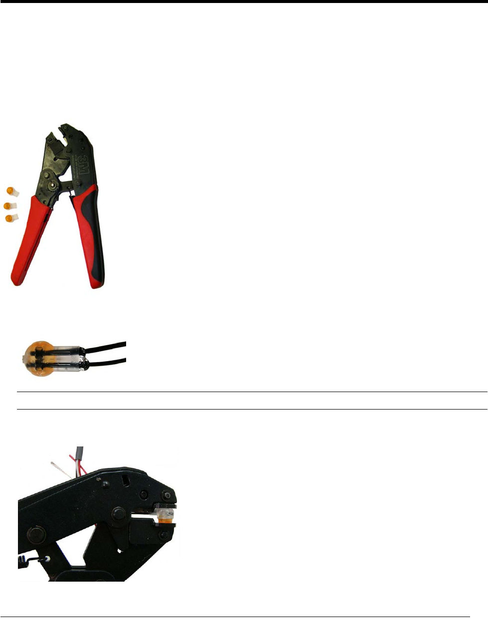
Required Materials
• E-9R 3M® gel cap crimping tool
• Itron Splice Kit (OEM-0034-002)
1. Push two wires as far as possible into the connector.
Caution Do not strip insulation from the ends of the wires before inserting them into the connector.
2. Carefully place the connector and wires into the jaws of the crimping tool. Make sure the wires remain
fully inserted in the gel-cap connector.
A
PPENDIX
B
Using Gel Cap Connectors and the Itron Splice Kit
Using Gel Cap Connectors and the Itron Splice Kit
TDC-0909-003 100W and 100WP Datalogging ERT Module Installation Guide 41
Proprietary and Confidential
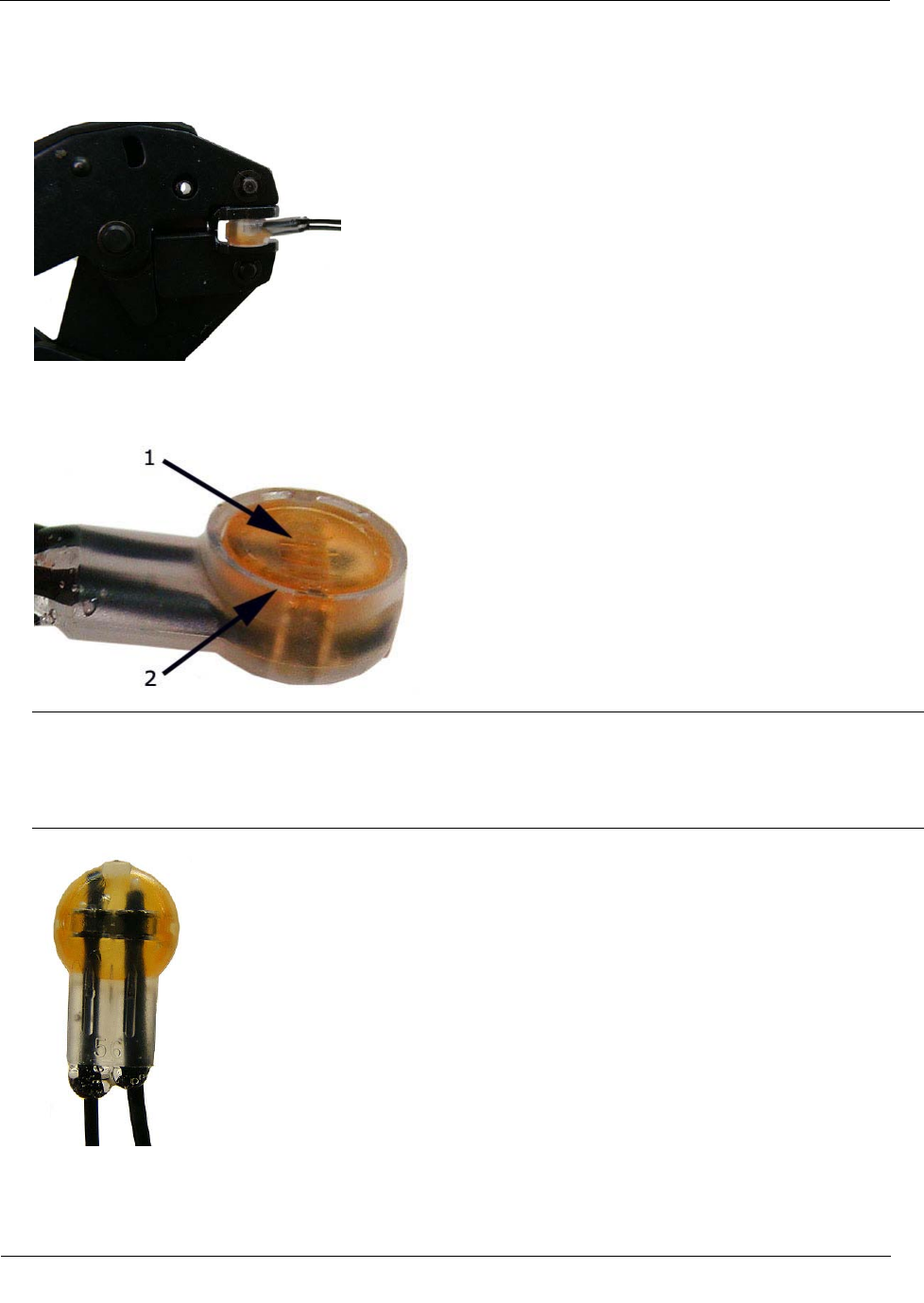
3. Crimp the connector by squeezing the handles until the connector cap is fully seated. Continue to apply
pressure for three seconds.
4. A connector is crimped properly when the top of the movable yellow center (1) is flush with the top of the
connector body (2).
Warning Crimping the connector forces some sealant out of connector. The sealant protects the inside of
the connector against insects, moisture, and other contaminants.
The sealant may cause minor eye and skin irritation. Avoid eye contact. Avoid prolonged or repeated skin
contact. Contact Itron Support for Material Safety Data Sheets (MSDS).
Using Gel Cap Connectors and the Itron Splice Kit
TDC-0909-003 100W and 100WP Datalogging ERT Module Installation Guide 42
Proprietary and Confidential
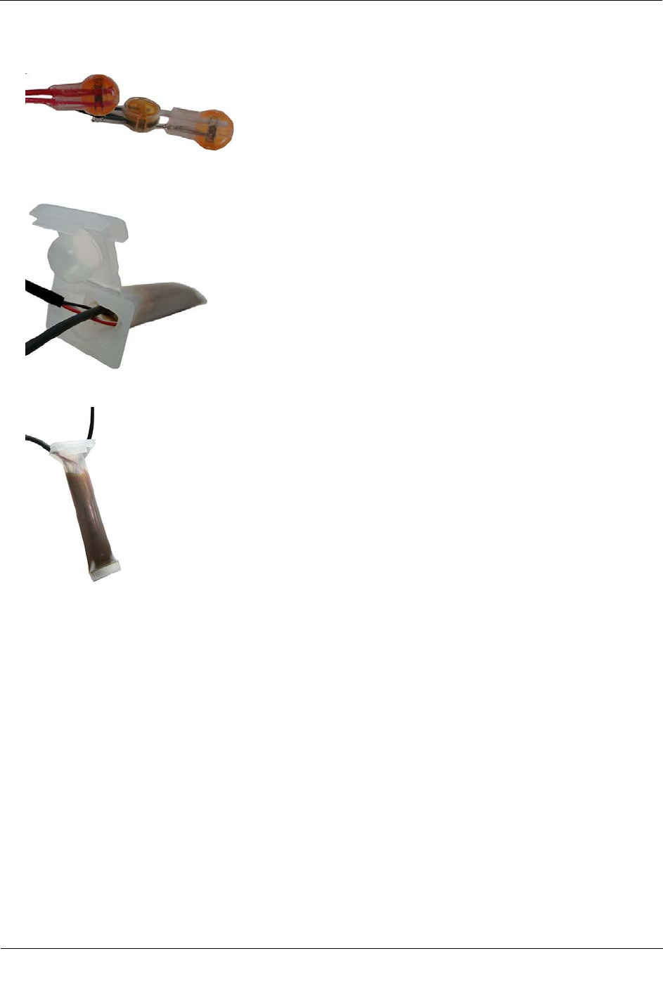
5. After you complete all ERT module to register wire connections, arrange the connectors in a single file.
6. Insert the connectors and wires into the splice tube until the connectors and wires completely immerse in
the tube's gel material.
7. Separate the cables to the sides and close the splice tube cover.
8. Discard any leftover materials from the customer premises.

TDC-0909-003 100W and 100WP Datalogging ERT Module Installation Guide 43
Proprietary and Confidential
This chapter provides the information to help you troubleshoot issues related to the 100W and 100WP ERT
modules.
The following table describes possible issues and provides suggested actions to resolve the issue.
Issue
Action
Cannot program the ERT module. Check the programming device and software version. Program ERT modules using
the FC300 handheld computer running Field Deployment Manager (FDM)
software.
Cannot read the ERT module. An ERT module that is not programmed will not transmit an SCM. Reprogram the
ERT module and perform a reread. If an ERT module is not initially programmed, it
will not bubble-up and listen for an SCM.
Marginal readability due to water ERT module
location (for example, an ERT module deep
inside a pit).
Consider reprogramming the endpoint for Hard-to-Read (H2R) mode. This
increases the output power to Fixed Network levels.
Note This mode will reduce battery life.
The ERT module in a Fixed Network is not
reporting. Perform a Check ERT and verify the ERT module is in FN mode. If the CCU's
pathway is obstructed, consider including an 8-channel repeater. Systems that utilize
Fixed Network v4.0 software and a CCU100 may require a Repeater 100.
The handheld programmer is locked up and
button presses produce no response. Soft boot the handheld by pressing and holding buttons A and B until the screen
fades. Release the buttons and allow the handheld to reboot.
A
PPENDIX
C
Troubleshooting

TDC-0909-003 100W and 100WP Datalogging ERT Module Installation Guide 44
Proprietary and Confidential
Symbols & Numbers
100W and 100WP ERT module Accessories, 12
100W and 100WP ERT modules with Integral
Connectors, 12
100W and 100WP Models, 4
100W and 100WP Transmission Modes, 5
100W Encoder Start-up, 10
100W Operating Modes, 5
100WP Operating Modes, 6
100WP Pulser Start-up, 11
A
About the 100W and 100WP ERT module, 3
B
Base Mount Installation, 19
Battery Life, 4
Before You Begin, 1
C
Connecting the 100WP to a Remote Meter
Register, 9
Connecting to a Meter Register Using a Cable, 7
Connecting to a Meter Register Using the Inline
Connector, 7
H
How This Document is Organized, 2
I
Initializing the 100W, 9
Initializing, Connecting, and Programming the
ERT Module, 7
Installing and Connecting, 7
Installing in a New Lid, 25
Installing the 100W and 100WP ERT module, 12
Installing the Remote Antenna, 35
O
Optional Leak Sensor Installation, 26
P
Pipe Preparation, 30
Programming the 100WP, 10
R
Related Documents, 2
Remote Antenna Installation, 34
Required Base Mounting Tools and Hardware, 19
Required Equipment, 26
Required Tools and Hardware, 14, 17, 20, 22
Rod Mount Installation, 14
S
Shelf Mount Installation, 20
T
Through Lid mount, 22
To connect the 100W to the register, 8
To connect the inline connector, 38
To connect the Leak Sensor to the 100W and
100WP ERT module, 27
To connect the remote antenna to the ERT module,
36
To install a Security Seal through the protective
connector cover, 13
To install in lids with holes using the Pit Lid
Mounting Kit (CFG-0771-011), 23
To install the 100W and 100WP ERT module on a
rod, 15
To install the 100W and 100WP ERT module
using the base mount procedure, 19
To install the 100W and 100WP ERT module
using the wall mount procedure, 17
To install the 100W in new lids, 25
To install the Leak Sensor on a pipe (up to 2 1/2-
inch OD), 32
To install the Leak Sensor on a pipe or meter
insetter, 30
To install using the shelf mount adapter, 21
Troubleshooting, 43
U
Using an Extension Cable, 9
Using an Inline Connector, 38
Using Gel Cap Connectors and the Itron Splice
Kit, 40
Index

Index
TDC-0909-003 100W and 100WP Datalogging ERT Module Installation Guide 45
Proprietary and Confidential
V
Verifying 100W and 100WP ERT module
Operation, 11
W
Wall Mount Installation, 17