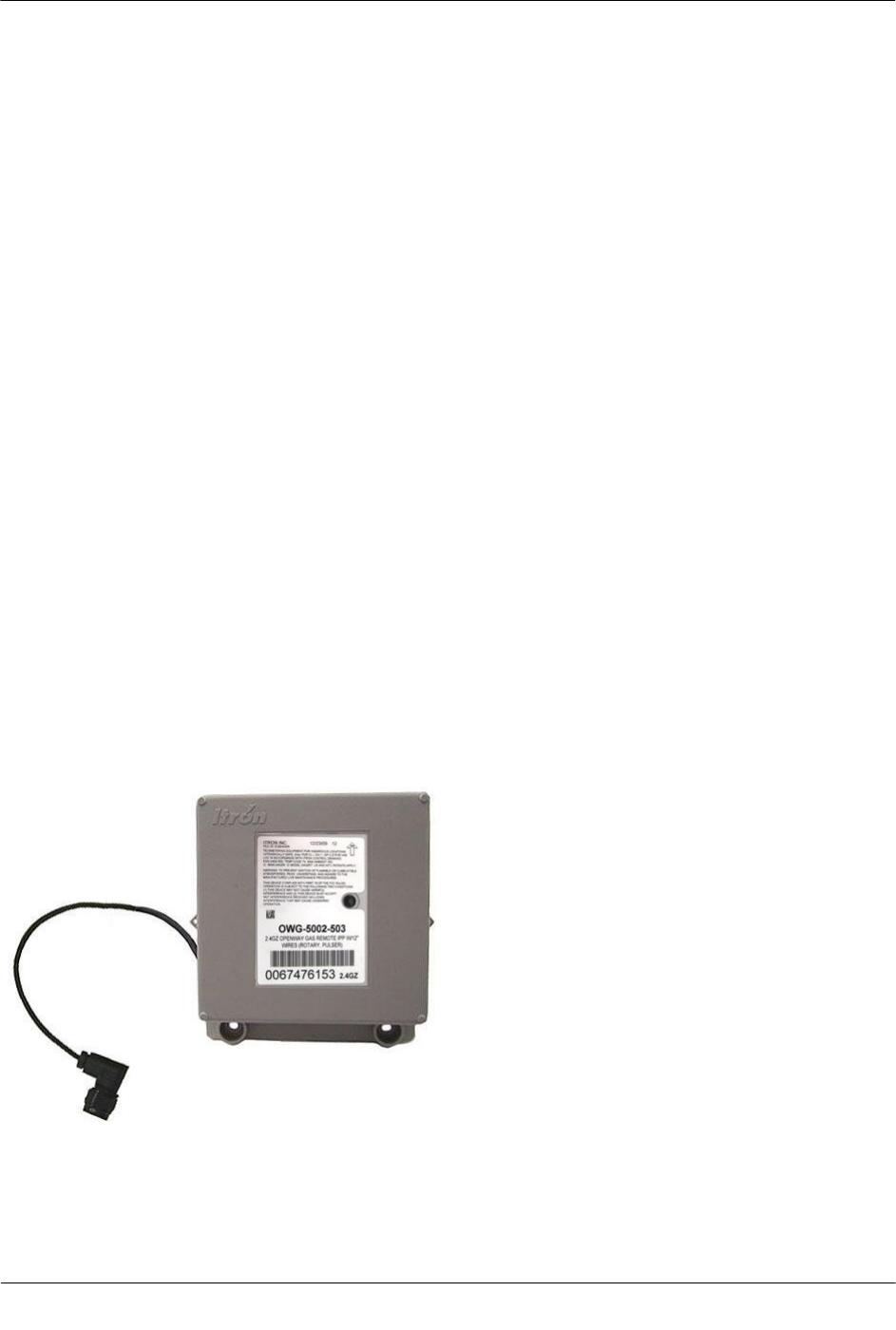
Itron 24GZRB AMR transceiver device for utility meters. User Manual Part2
Itron, Inc. AMR transceiver device for utility meters. Users Manual Part2
Itron >
Contents
- 1. Users Manual Part1
- 2. Users Manual Part2
Users Manual Part2

Electronic Instrument Installation
TDC-0838-001 2.4GZ OpenWay Gas Module Installation Guide - Remote Mount 51
Proprietary and Confidential
Installing the Module to the Dresser ROOTS® Micro Corrector
(IMC/W2 or MC2)
Dresser ROOTS® Meters and Instruments offer a mounting bracket kit assembly to direct mount Itron's 2.4GZ
OpenWay remote gas module to the IMC/W2.
Dresser ROOTS® Meters Instruments Mounting Bracket Kit
(Dresser ROOTS Part Number 057783-000)
Quantity
Description
Dresser ROOTS® Part Number
1
Mounting bracket
015951-000
1
Screw, 8-32 x 7/16-inch
000163-277
2
Screw, 8-32 x 3/4-inch
000163-282
3
Nut, 8-32
012829-005
4
Spacer, #10
053669-001
4
Endpoint/bracket mounting screw, M6 x 20 mm
013444-002
Important Dresser ROOTS® mounting bracket kit does not include the cable required
to connect the 2.4GZ OpenWay remote mount gas module to the Amphenal connector
on the IMC\W2.
Dresser ROOTS® Accessories
Description
Dresser ROOTS® Part Number
9" A-B male cable
054983-012
9" D-E male cable
054983-010
Electronic Instrument Installation
TDC-0838-001 2.4GZ OpenWay Gas Module Installation Guide - Remote Mount 52
Proprietary and Confidential
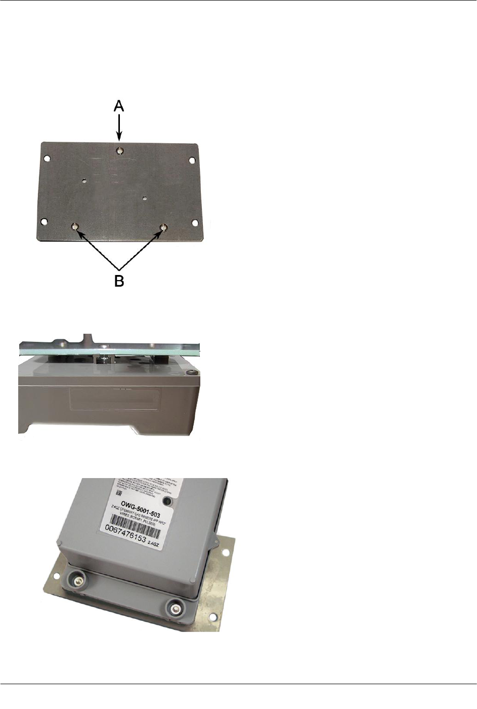
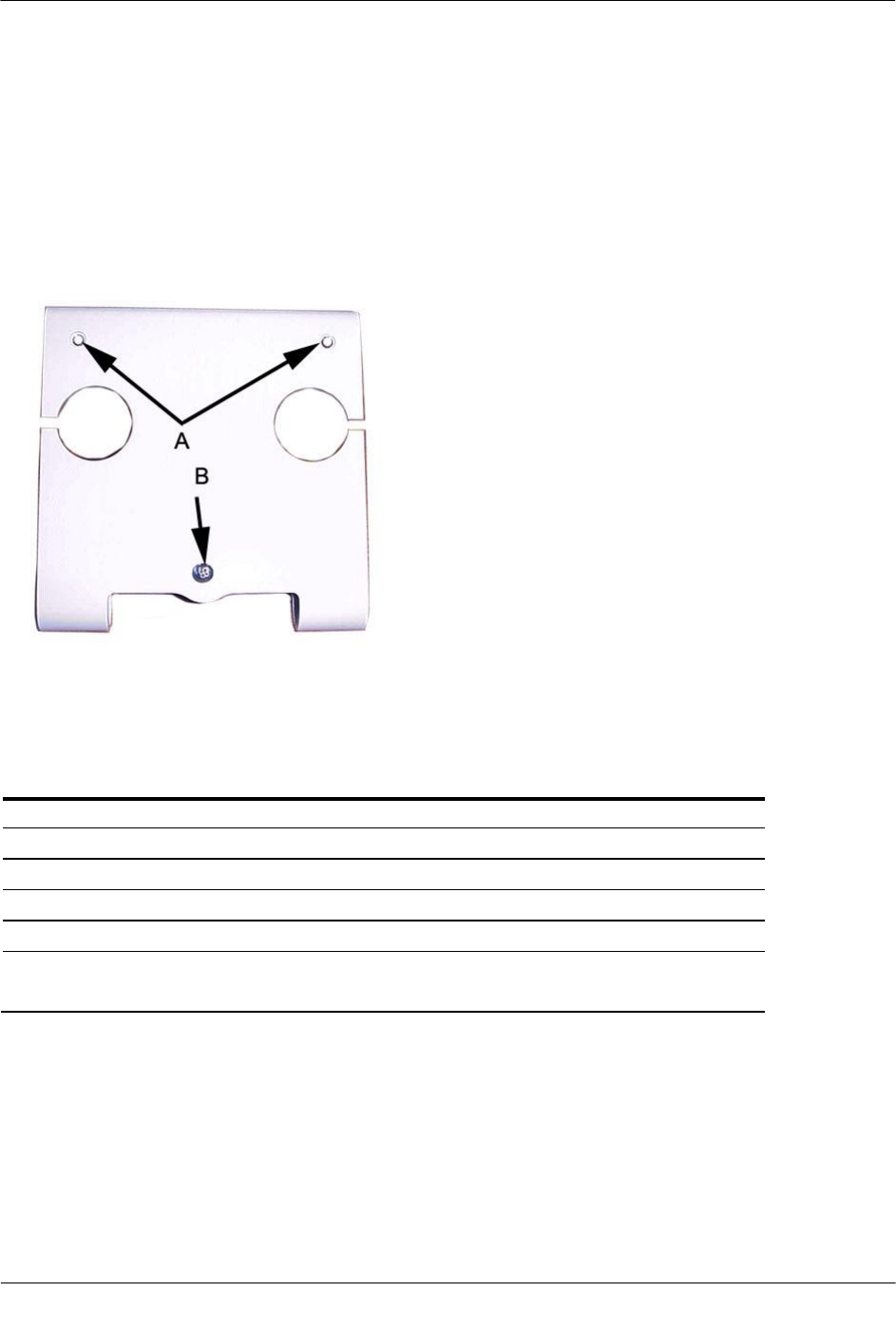
To attach the module to the IMC\W2 and MC2
1. Insert the 8-32 x 7/16-inch screw (A) into the top of the mounting bracket. Insert the two 8-32 x 3/4-inch
screws (B) into the bottom of the mounting bracket.
2. Insert one 3/32-inch nut on the top 7/16-inch bracket screw (A). Slide the 2.4GZ OpenWay remote mount
gas module mounting lug over the top of the bracket screw and nut.
3. Secure the bottom 2.4GZ OpenWay remote mount gas module mounting holes over the two 8-32 x 3/4-
inch screws with the remaining two 8-32 nuts.
Electronic Instrument Installation
TDC-0838-001 2.4GZ OpenWay Gas Module Installation Guide - Remote Mount 53
Proprietary and Confidential
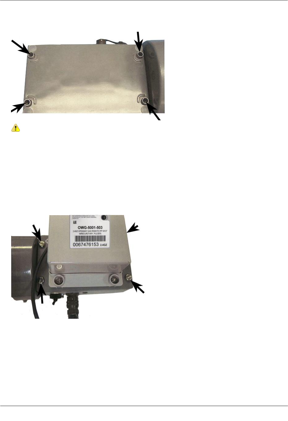
4. Insert the #10 spacers into the four mounting holes on the back of the IMC\W2.
Caution Vertical mounting position is important to maximize RF performance. You can mount
a 2.4GZ OpenWay remote gas module with the module's label arrow pointing up or down,
dependent upon the application as noted in relevant sections of this installation manual. The
module's arrow must never point to either side. The module's tilt tamper functionality is
designed to operate with the module installed vertically. The 2.4GZ module's tilt tamper will
operate with the label arrow pointed up or down. The module's tilt tamper will not operate with
the module installed horizontally (the label arrow pointed to either side).
5. Secure the module/bracket assembly on the IMC\W2 using four module/mounting bracket screws (M6 x
20 mm).
Electronic Instrument Installation
TDC-0838-001 2.4GZ OpenWay Gas Module Installation Guide - Remote Mount 54
Proprietary and Confidential
6. There are two options to connect the 2.4GZ remote gas module to Dresser ROOTS to the IMC\W2:
1. For the Amphenol connector: plug the connector from the Itron endpoint to the IMC\W2 volume
input connector.
2. For the cable gland or conduit fitting:
a. Route the cable from the 2.4GZ OpenWay remote mount gas module through the IMC\W2 cable
gland/conduit connector.
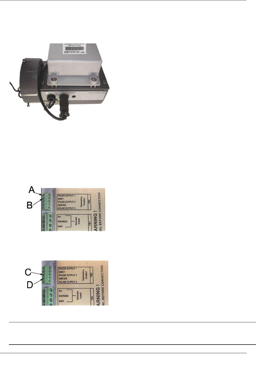
To receive uncorrected reads: connect the red wire to the terminal block 3 (TB3 telemetry output)
GND1 (ground) position (B). Connect the white and blue wires to the pulse output 1 position (A).
To receive corrected reads: connect the red wire to the GND 2/3 (ground) TB3 telemetry output
position (C). Connect the white and blue wires to the pulse output 2 position.
b. Tighten the cable gland fitting around the cable. Apply 15 inch-pounds torque.
Note 2.4GZ OpenWay remote mount gas modules using the flying lead cable assembly (Dresser
ROOTS® part number 055018-700) are factory wired to terminal block 3 (TB3) according to IMC\W2
pulse output default configuration. Consult the customer specification for other wiring configurations.
Electronic Instrument Installation
TDC-0838-001 2.4GZ OpenWay Gas Module Installation Guide - Remote Mount 55
Proprietary and Confidential
To test the 2.4GZ OpenWay remote mount gas module IMC\W2 installation
1. Connect the IMC\W2 to the PC using the serial cable.
2. Using the Dresser ROOTS® User Terminal (UT) communications software, connect to the IMC\W2.
3. Read the uncorrected or corrected count number on the 2.4GZ OpenWay remote mount gas module with
the Itron endpoint reading device. Compare the IMC\W2 uncorrected or corrected amounts to the 2.4GZ
OpenWay remote mount gas module.
4. Input approximately 20 pulses to the 2.4GZ OpenWay remote mount gas module. Verify the uncorrected
or corrected counts on the IMC\W2 and the 2.4GZ OpenWay remote mount gas module are the same.
Programming the 2.4GZ OpenWay Remote Mount Gas Module
Assembly
Caution The 2.4GZ Remote Mount Gas Module must be programmed before use.
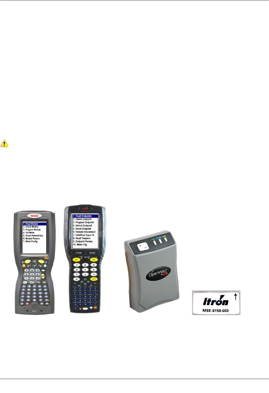
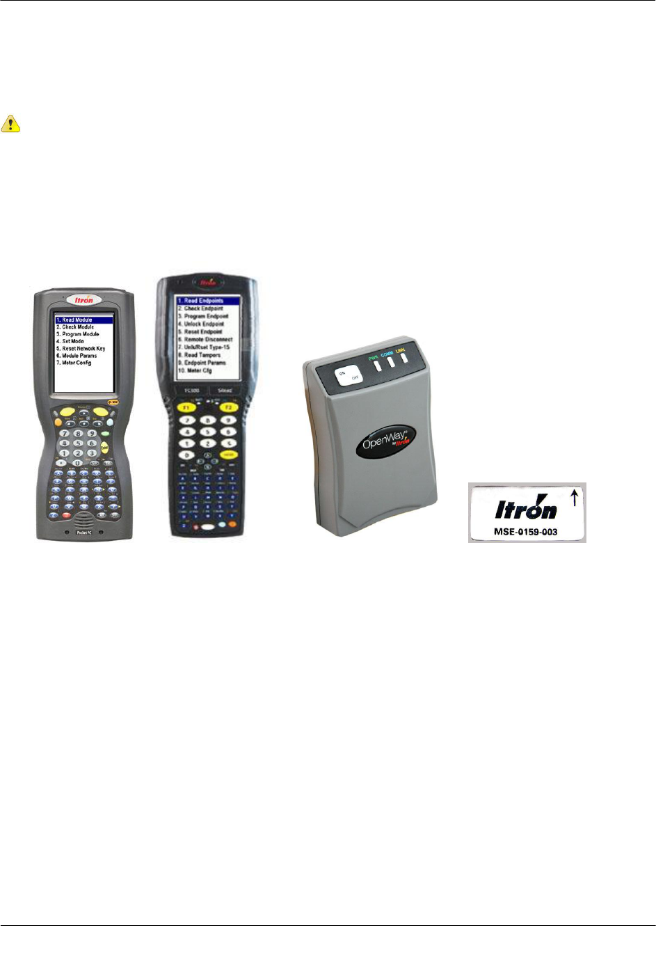
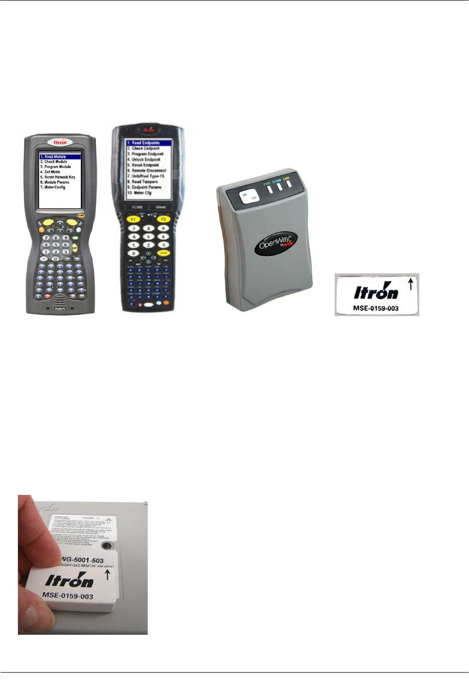
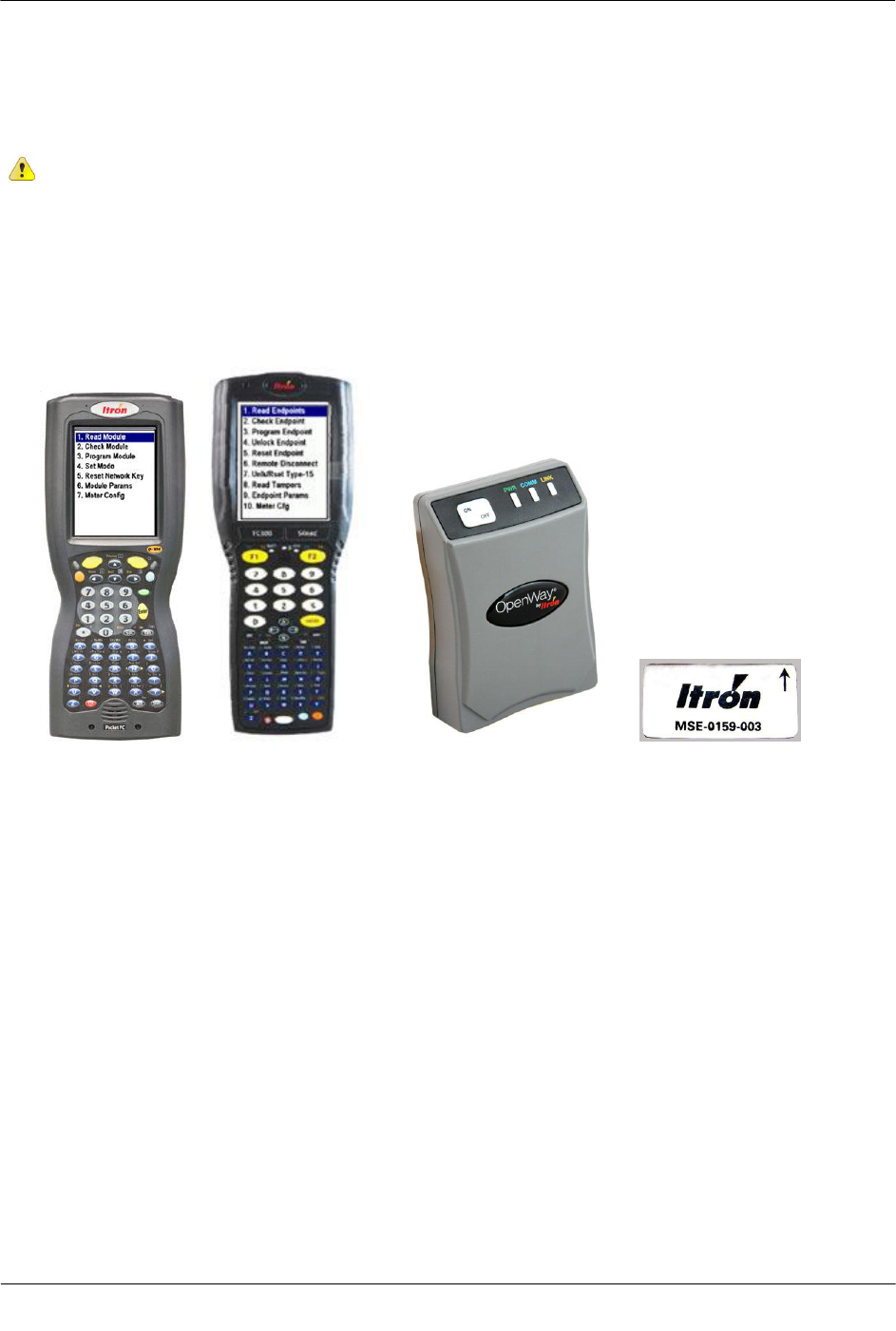
Program the 2.4GZ OpenWay remote mount gas module with a Bluetooth-enabled FC200 or FC300 with
SRead handheld computer and ZigBee Belt Clip Radio loaded with Endpoint-Link or Endpoint-Link Pro
software version 5.3.1.26 or version 5.5 for Itron Private Profile (IPP) gas modules (OWG-5001-XXX).
Endpoint-Link Pro software version 5.5 must be used for Smart Energy Profile (SEP) gas modules
(OWG-5002-XXX). See the Endpoint-Link Endpoint Programming Guide (TDC-0744) for more
complete programming information. An Itron magnet is also required for programming.
FC200SR FC300 with SRead Zigbee Belt Clip Radio Itron Magnet
Electronic Instrument Installation
TDC-0838-001 2.4GZ OpenWay Gas Module Installation Guide - Remote Mount 56
Proprietary and Confidential
To program the 2.4GZ OpenWay remote mount gas module
1. Program the meter drive rate into the 2.4GZ OpenWay remote mount gas module using the handheld
computer and Belt Clip Radio. Programming parameters are based on the configuration file loaded into
the handheld computer.
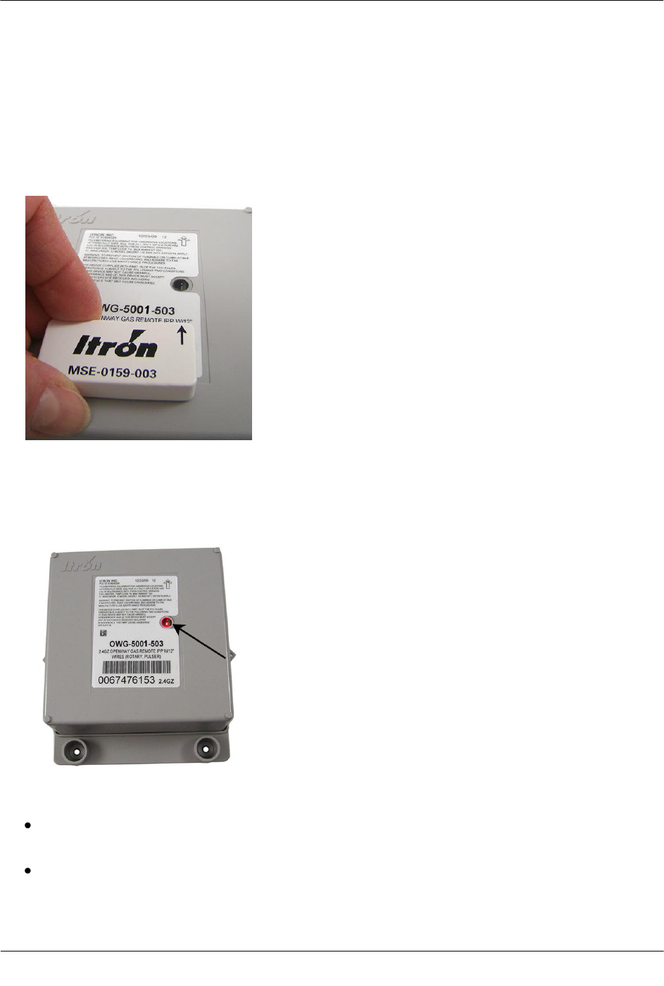
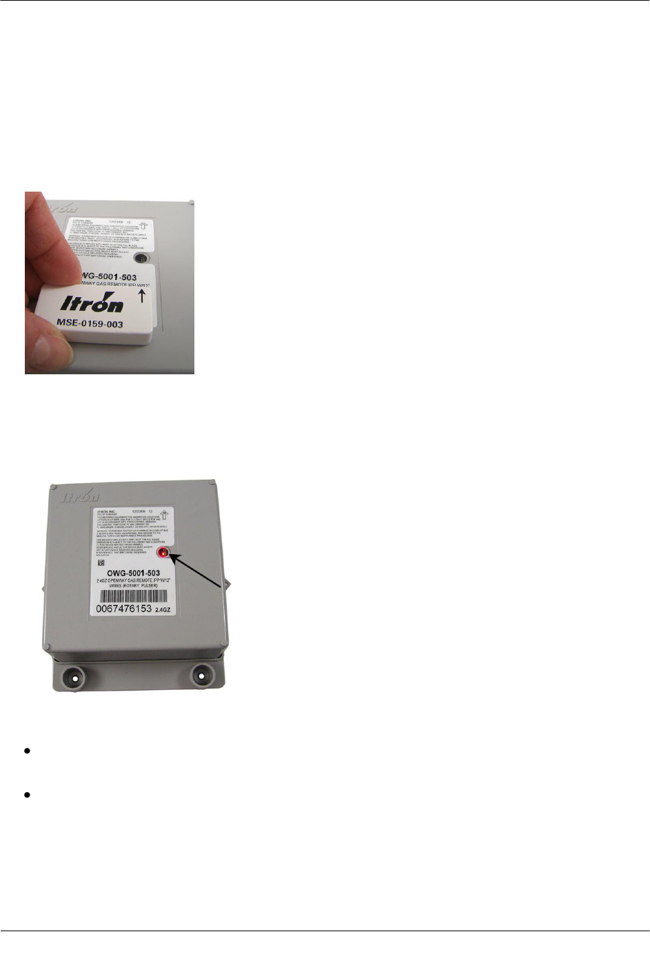
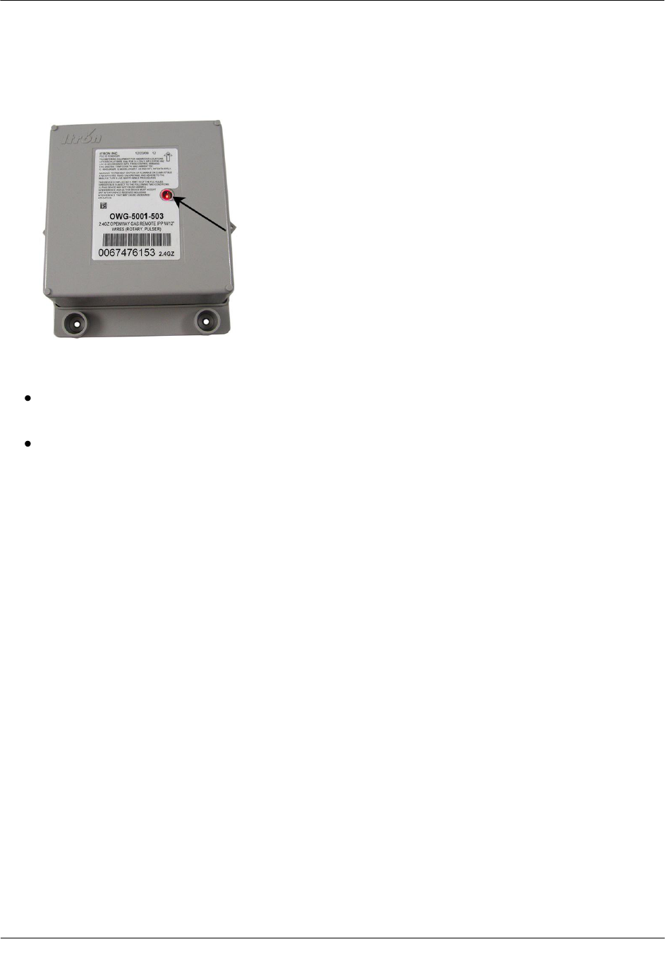
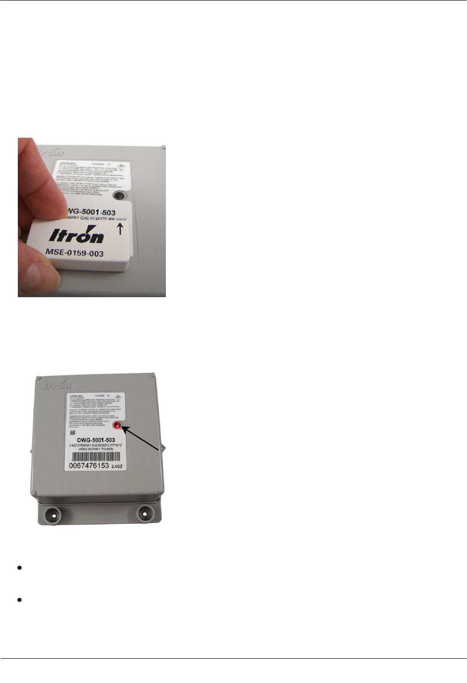
2. Place the magnet over the barcode on the module cover label with the magnet face (inked Itron logo and
part number) arrow pointed up toward the top of the module.
3. Hold the magnet in place for 5 seconds and remove it.
4. The LED will blink red three times. This signifies the 2.4GZ OpenWay remote mount gas module is
searching for a programming device. Within a few seconds of locating the handheld computer, the red
LED will blink five more times. The handheld computer will confirm programming success or failure.
5. Read the 2.4GZ OpenWay remote mount gas module using the handheld computer and Belt Clip Radio.
If the read result is higher than the number programmed in Step 1, the 2.4GZ OpenWay remote mount
gas module is counting correctly.
If the read result is not higher than the number programmed in Step 1, replace the 2.4GZ OpenWay
remote mount gas module.

TDC-0838-001 2.4GZ OpenWay Gas Module Installation Guide - Remote Mount 57
Proprietary and Confidential
This chapter provides the instructions to install Remote 2.4GZ OpenWay remote mount gas modules (Itron
part number OWG-5001-501 and OWG-5002-501 with 2.5 foot cable and encoder) on the diaphragm gas
meters where a direct mount endpoint is not possible. Reference the Itron Gas Endpoint Meter Compatibility
List (PUB-0117-002 or the 2.4GZ OpenWay remote mount gas module Meter Compatibility List on page 3
for compatible diaphragm meters.
Tools and Materials Supplied By You
Note 2.4GZ OpenWay remote mount gas module installation to a diaphragm meter may require
additional tools and materials over those listed in Installation Prerequisites on page 7.
The following user/installer-supplied tools and materials are required to install, program, and check the 2.4GZ
OpenWay remote mount gas module:
Medium flat-blade screwdriver
Medium flat-blade, torque-measuring screwdriver
Medium Philips screwdriver
Pliers
Side-cutting pliers or similar tool
1/4-inch nut driver or other blunt tool for seating endpoint tamper
Itron programming device to program and check 2.4GZ OpenWay remote mount gas module installation
and operation:
FC300 with SRead with Endpoint-Link or Endpoint Link Pro version 5.5 or higher or
FC200 (with Bluetooth-enabled) handheld computer loaded with Endpoint-Link or Endpoint-Link Pro
software to program and check endpoint.
ZigBee Belt-clip Radio with Endpoint-Link or EndPoint-Link Pro software - to program and check
2.4GZ OpenWay remote mount gas module installation and operation.
Caution You must program the 2.4GZ OpenWay remote mount gas module with a Bluetooth-
enabled FC200 or FC300 with SRead handheld computer and ZigBee Belt Clip Radio loaded
with EndPoint-Link Pro software version 5.3.1.26 or version 5.5 for Itron Private Profile (IPP)
gas modules (OWG-5001-XXX).
Endpoint-Link Pro software version 5.5 must be used for Smart Energy Profile (SEP) gas
modules (OWG-5002-XXX).
1-inch putty knife or similar tool to remove old gasket material from the meter and index cover
Replacement temperature compensation (TEMP COMP) meter index stickers (if required)
CH A P T E R 5
Diaphragm Meter Installation
Diaphragm Meter Installation
TDC-0838-001 2.4GZ OpenWay Gas Module Installation Guide - Remote Mount 58
Proprietary and Confidential
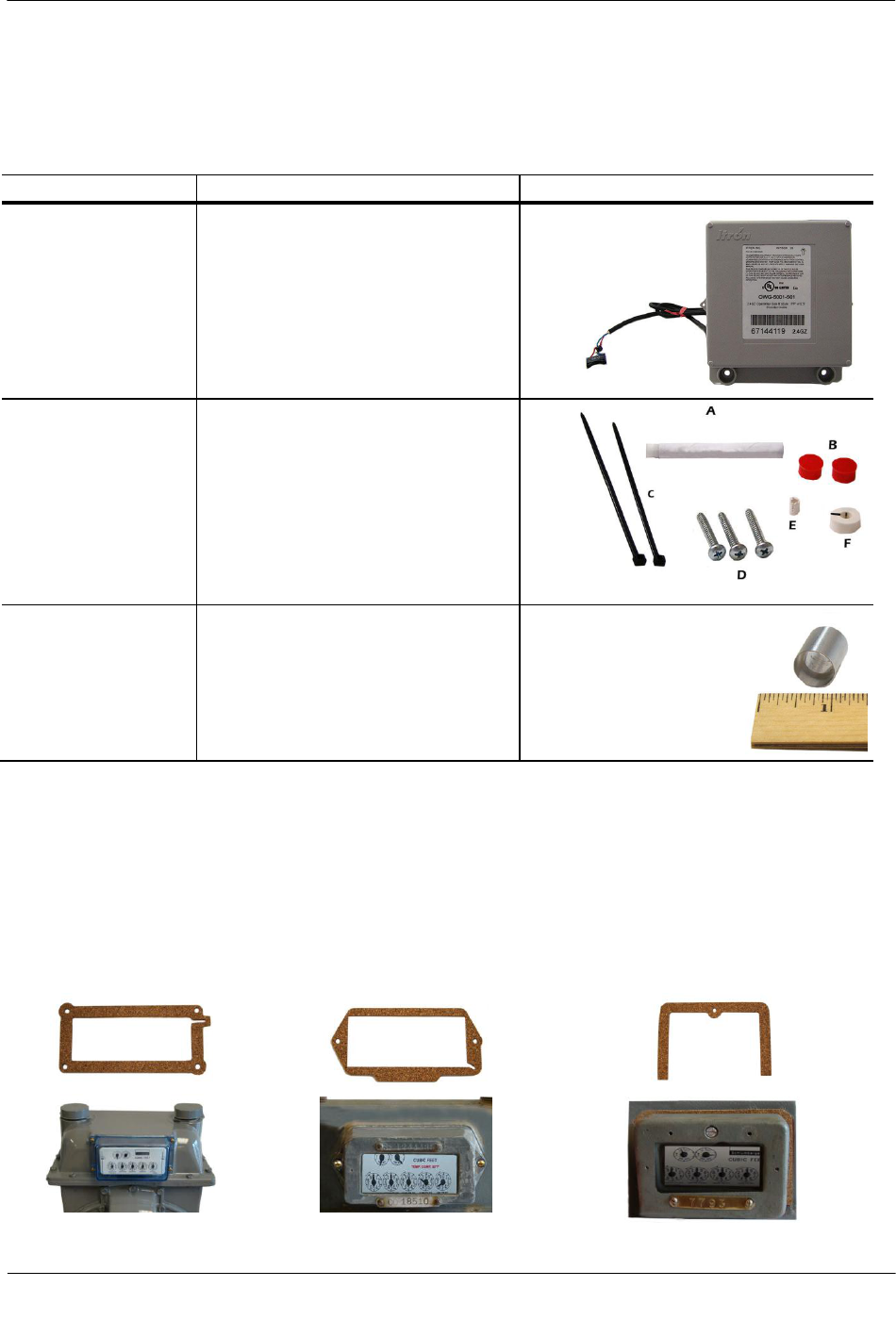
Materials Available from Itron
The following items are required for each 2.4GZ OpenWay remote mount gas module installation to a
diaphragm gas meter:
Itron Part Number
Description
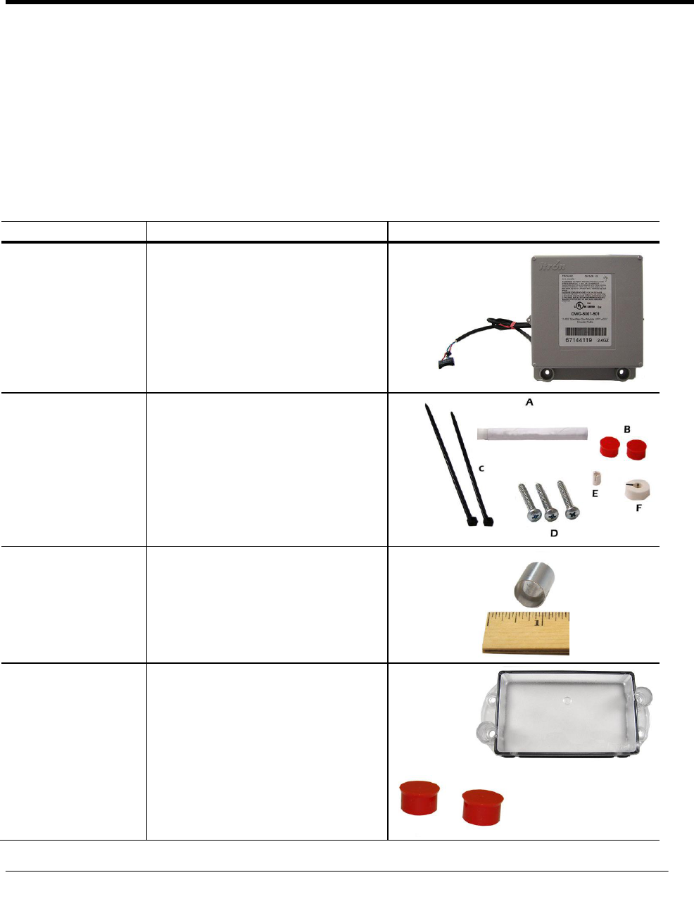
OWG-5001-501
OWG-5002-501
2.4GZ OpenWay Remote Mount Module -
IPP
2.4GZ OpenWay Remote Mount Module -
SEP
CFG-0081-001
Remote Mount Encoder Kit
A Acetone applicator stick
B Tamper Seals
C Cable ties
D Mounting screws
E Hub spacer
F Magnet hub
013-1723-112
Encoder Spacing Tool
(Use the Encoder Spacing Tool to ensure the
encoder mounts the correct distance from the
magnet hub on the meter index.)
Replacement Gaskets
The Itron replacement index cover gaskets shown below are thicker than standard gaskets and have a special
slot to accommodate the encoder cable. Gaskets are specific to Schlumberger/Sprague model 675 and 1000
commercial diaphragm meters
4-hole front cover gasket:
Itron part number
FAB-0014-003
2-hole front cover gasket:
Itron part number
FAB-0014-002
1-hole front cover gasket:
Itron part number
FAB-0014-001
Diaphragm Meter Installation
TDC-0838-001 2.4GZ OpenWay Gas Module Installation Guide - Remote Mount 59
Proprietary and Confidential
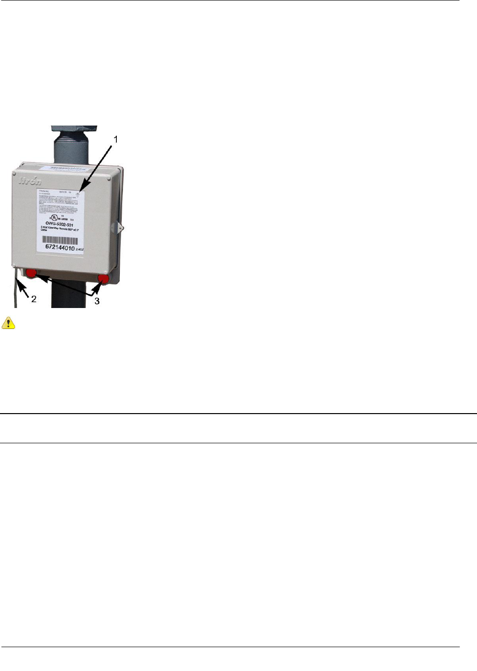
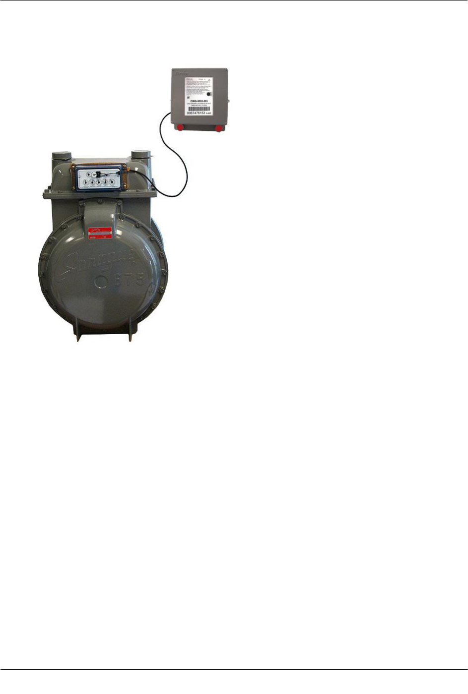
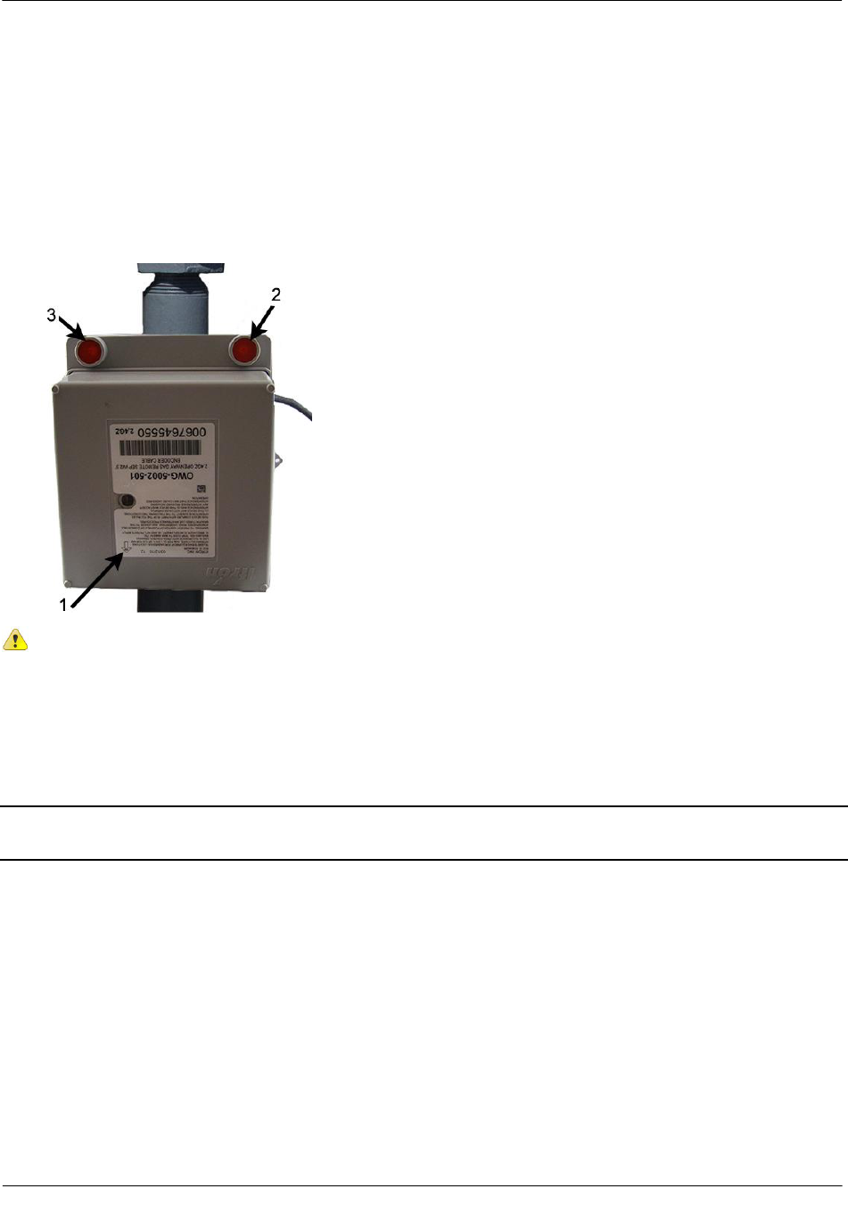
Installing the 2.4GZ OpenWay Remote Mount Gas Module
The 2.4GZ OpenWay remote mount gas module mounts on a pipe using the Remote Mount Installation Kit
(Itron part number CFG-0005-003) or a vertical flat (wall) surface. Always mount the 2.4GZ OpenWay
remote mount gas module with the printed label right-side-up (arrow pointing up -1), and the encoder wires
(2) and tamper seals (3) at the bottom, as shown.
Caution Vertical mounting position is important to maximize RF performance. You can mount a
2.4GZ OpenWay remote gas module with the module's label arrow pointing up or down,
dependent upon the application as noted in the relevant section of this installation manual. The
module's arrow must never point to either side. The module's tilt tamper functionality is designed
to operate with the module installed vertically. The 2.4GZ module's tilt tamper will operate with the
label arrow pointed up or down. The module's tilt tamper will not operate with the module installed
horizontally (the label arrow pointed to either side).
Note The occurrence of false tampers may increase on inverted 2.4GZ modules installed in high vibration
areas.
Diaphragm Meter Installation
TDC-0838-001 2.4GZ OpenWay Gas Module Installation Guide - Remote Mount 60
Proprietary and Confidential
Installing 2.4GZ OpenWay Remote Mount Gas Module Encoders
Caution To insure proper adhesion, the 2.4GZ OpenWay remote mount gas module encoder
must be installed at temperatures between 40° to 95° Fahrenheit.
There are four tasks when installing the 2.4GZ OpenWay remote mount gas module with an encoder on a
diaphragm meter:
Remove the index cover and any gasket residue.
Install the 2.4GZ OpenWay remote mount gas module encoder on the index.
Program the 2.4GZ OpenWay remote mount gas module.
Attach the index cover to the meter.
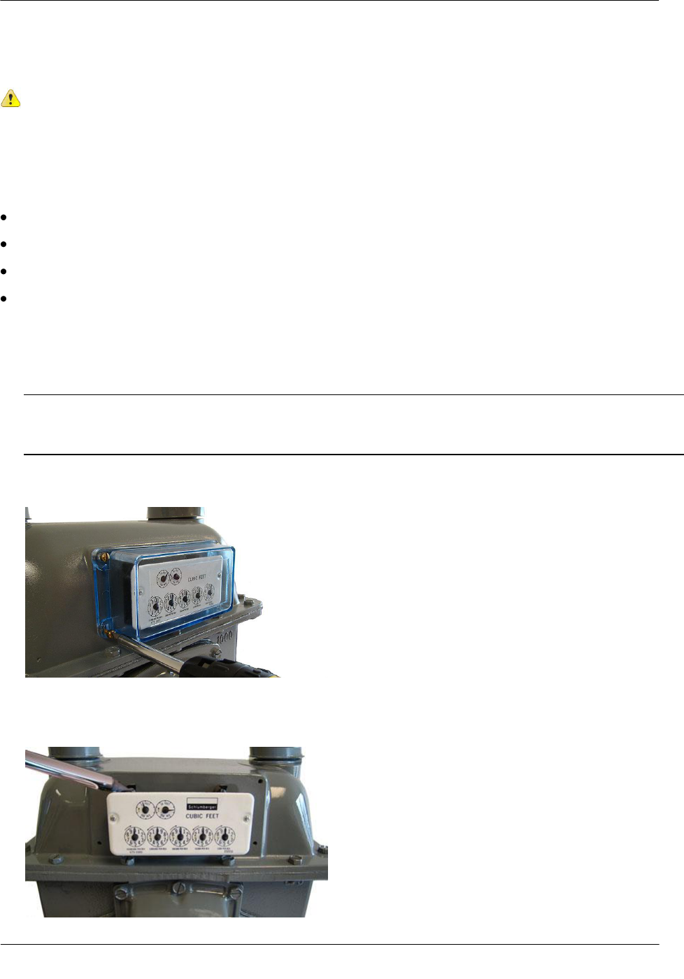
To remove the index
Note Properly dispose all unused screws, old index covers, gaskets, tamper seals, and other leftover
materials. Do not leave materials on customer premises. Replace any stripped, worn, or corroded
mounting screws.
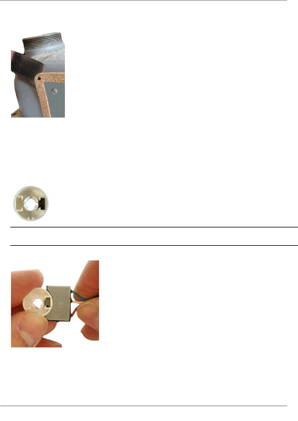
1. Cut and remove any wire seal routed through the index cover screws. Remove the index cover and set
aside. Remove the index mounting screws in an alternating fashion.
2. Remove the two index screws in an alternating fashion. Loosen the left index screw two turns, loosen the
index screw three to four turns. Hold the index while removing the screws to keep the index from falling.
Set the index aside where it will not be damaged.
Diaphragm Meter Installation
TDC-0838-001 2.4GZ OpenWay Gas Module Installation Guide - Remote Mount 61
Proprietary and Confidential
3. Remove old gasket and any gasket residue from the meter and index cover.
4. Use the FC200 or FC300 to read the 2.4GZ OpenWay remote mount gas module and record the reading
for comparison with progressive readings as installation is completed.
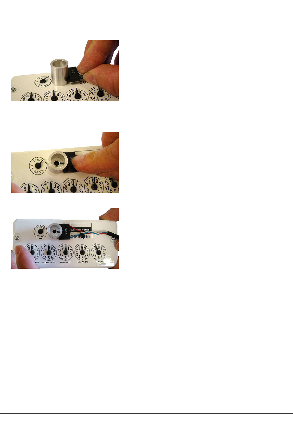
To install the encoder
1. Take the magnet hub from the Encoder Installation kit ( Itron part number CFG-0081-001).
2. Verify there is only one magnet in the hub.
Note If there is no magnet or if there are two magnets in the magnet hub, discard the magnet hub and use
a hub with one magnet.
3. Briefly place the magnet side of the magnet hub into the curved indentation in the encoder, as shown.
4. Take the magnet hub away from the encoder and set it at least one inch away from the encoder.
5. Use the FC200 to read the 2.4GZ OpenWay remote mount gas module. If this reading is higher than the
reading taken after removing the index, the 2.4GZ OpenWay remote mount gas module is counting and
working properly.
Diaphragm Meter Installation
TDC-0838-001 2.4GZ OpenWay Gas Module Installation Guide - Remote Mount 62
Proprietary and Confidential
Note If the reading is not higher than the previous reading, the 2.4GZ OpenWay remote mount gas
module is not reading. Repeat steps 3, 4, and 5. If the 2.4GZ OpenWay remote mount gas module is still
not counting, replace the 2.4GZ OpenWay remote mount gas module and perform steps 3, 4, and 5.
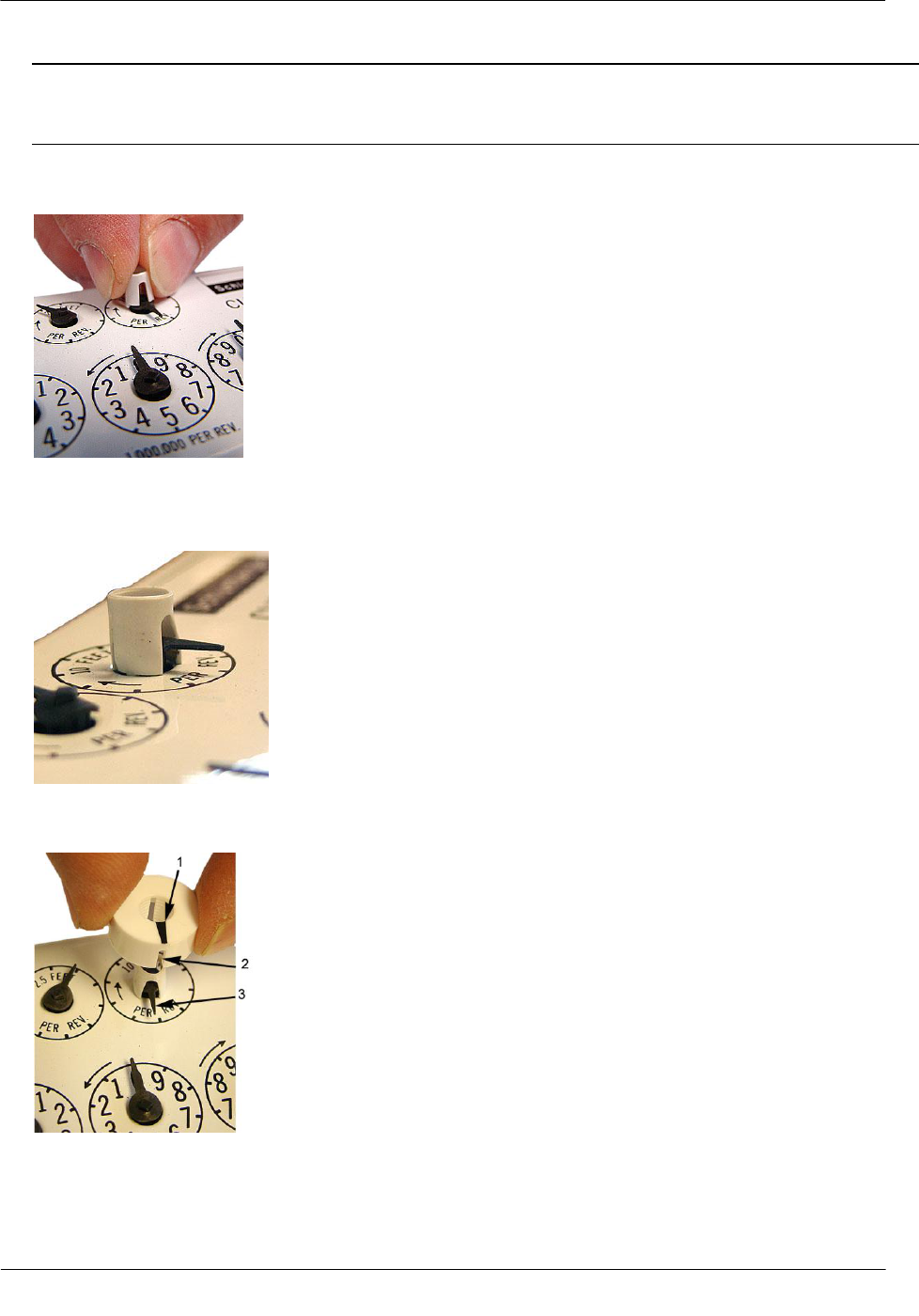
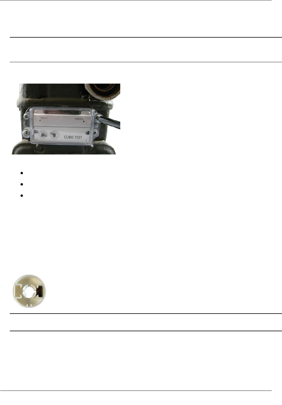
6. Align the large notch in the side of the magnet hub spacer with the needle of the meter drive rate dial (1
foot or 2 foot for residential diaphragm meters; 5, 10, or 100-foot for commercial diaphragm meters).
7. Press the magnet hub spacer down over the dial needle as far as possible. The tip on the bottom of the
spacer may touch index face. Turn the dial after hub spacer installation to verify the index dial functions
with a smooth, easy rotation.
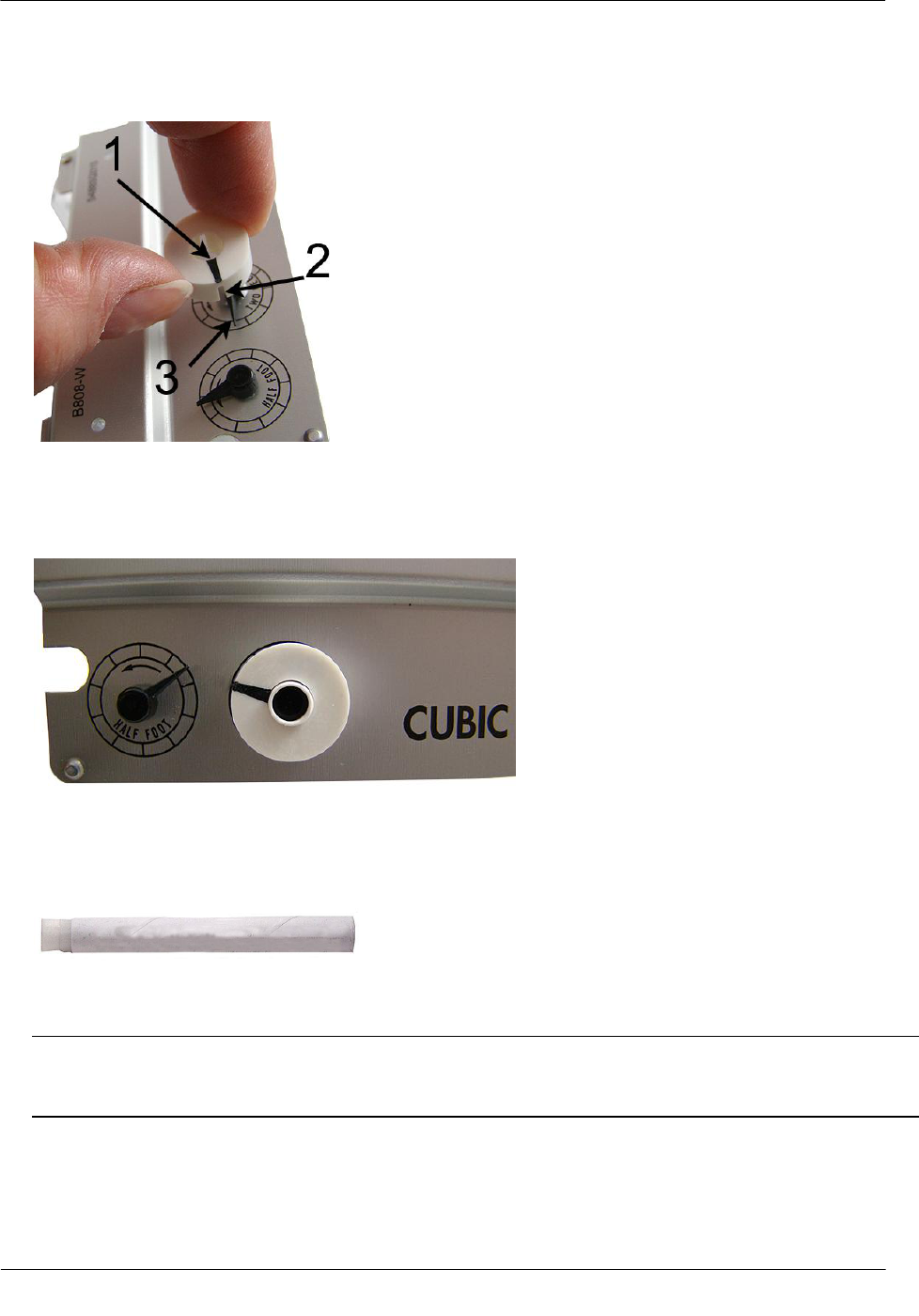
8. Align the pointer (1) on the top of the magnet hub and the notch (2) in the side of the magnet hub with the
needle (3) of the meter drive rate dial.
Diaphragm Meter Installation
TDC-0838-001 2.4GZ OpenWay Gas Module Installation Guide - Remote Mount 63
Proprietary and Confidential
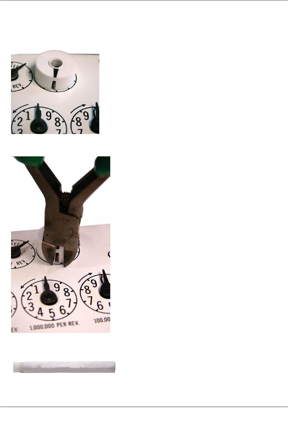
9. Press the magnet hub down over the hub spacer as far as possible. The bottom of the hub spacer may
touch the index face. Turn the dial after magnet hub installation to verify the index dial functions with a
smooth, easy rotation.
10. If the tip of the dial needle sticks out past the edge of the magnet hub, cut off the end of the dial needle as
close as possible to the magnet hub with a sharp, side-cutting pliers.
11. Take the acetone stick applicator from the Remote Encoder Installation Kit (Itron part number CFG-0081-
001).
12. Select a location on the index face next to the magnet hub. After encoder installation, the encoder cable
must not interfere with the index dials.
Diaphragm Meter Installation
TDC-0838-001 2.4GZ OpenWay Gas Module Installation Guide - Remote Mount 64
Proprietary and Confidential
Note If a TEMP COMP sticker is attached to the index where the encoder cable will mount, remove it
before cleaning with the acetone stick. If the sticker (or replacement sticker) must be put back on the
register face, place it in a new location on the index face after the encoder is attached.
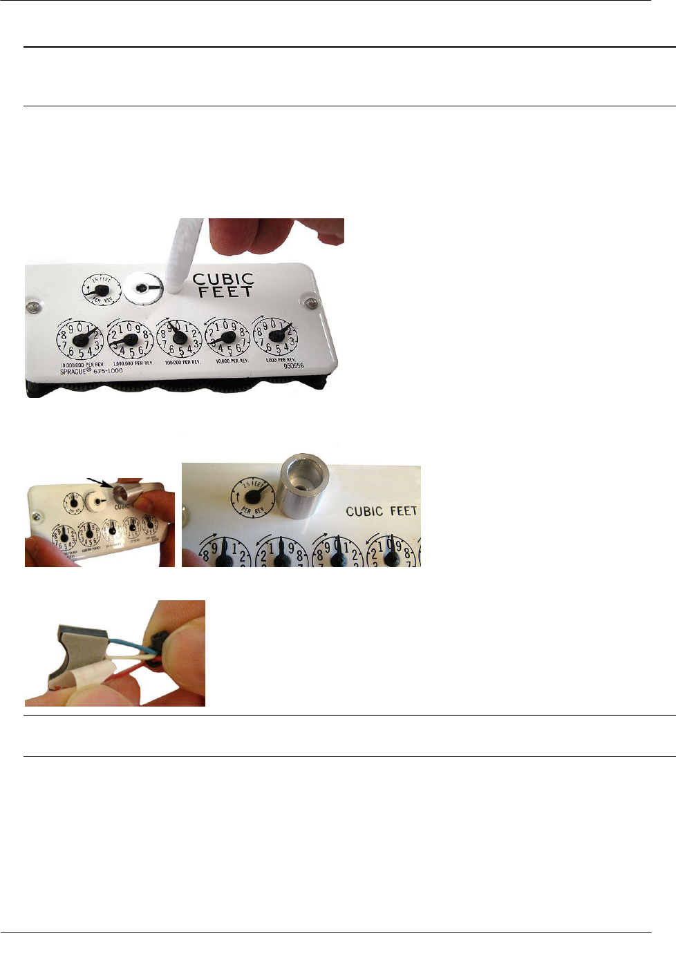
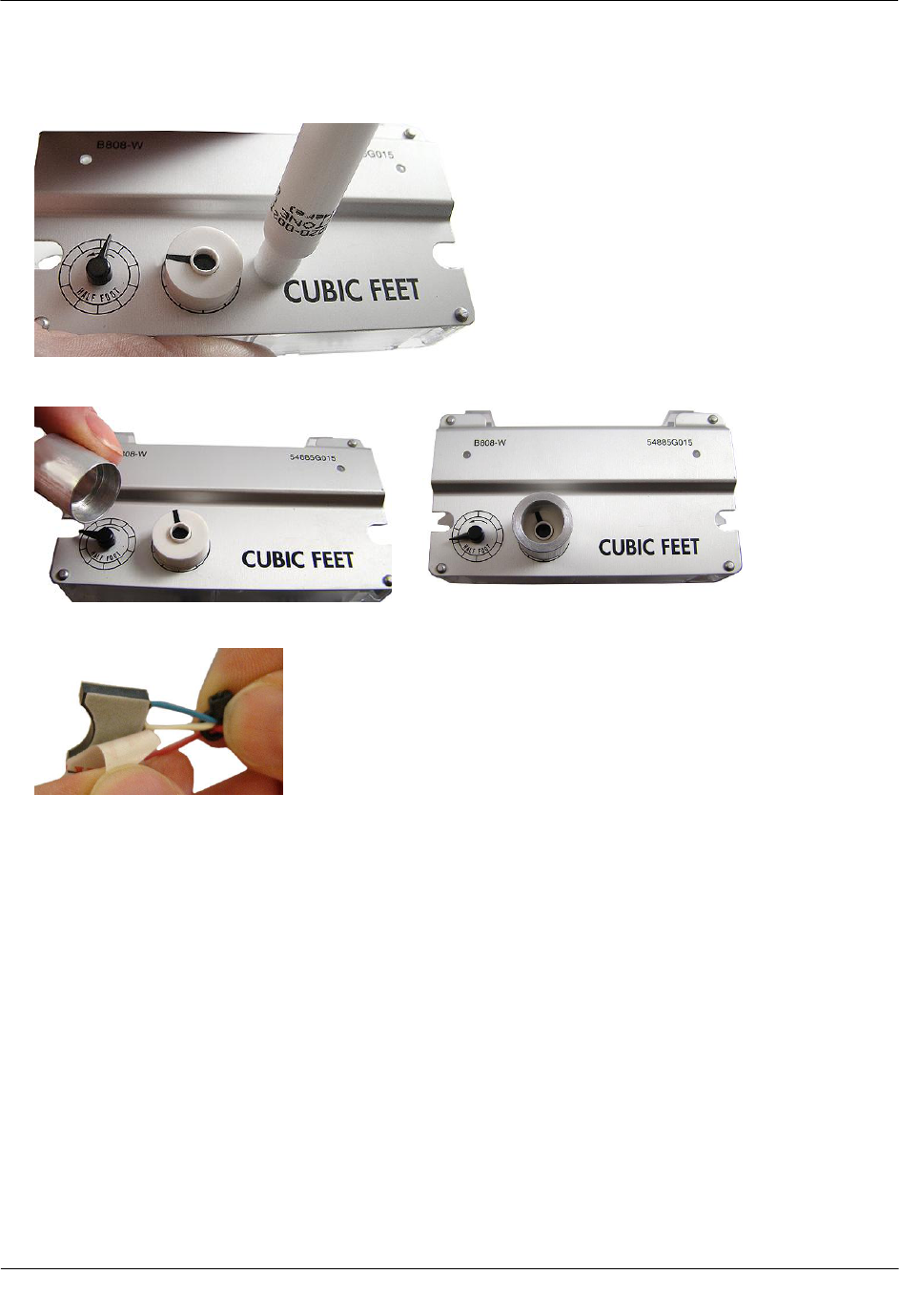
13. Tilt the acetone stick vertically with the wick end down. Squeeze the acetone stick on the black dot until
the packet inside the pen breaks. Continue to hold acetone stick vertical until the acetone wicks into the
foam applicator end.
14. Thoroughly apply acetone the area where the encoder will be installed. Do not touch the cleaned area of
the index face before the encoder is installed.
15. Slide the thin end of the encoder spacing tool down over the magnet hub.
16. Peel the strip of protective plastic off the adhesive side of the endpoint's encoder.
IMPORTANT You must do the next two steps exactly as described or the 2.4GZ OpenWay remote
mount gas module will not work properly.
Diaphragm Meter Installation
TDC-0838-001 2.4GZ OpenWay Gas Module Installation Guide - Remote Mount 65
Proprietary and Confidential
17. Press the curved side of the encoder firmly against the side of the encoder spacing tool as shown below,
with the adhesive side down.
18. Slide the encoder down along the side of the encoder spacing tool until it touches the surface of the index
(as shown below). Using moderate pressure, hold the encoder firmly against the index, without moving,
for 15 seconds to permanently apply the encoder.
The photo below shows how the encoder spacing tool and encoder will look after the 15 second wait time.
19. Remove the encoder spacing tool, set it aside, and lay the index on a flat, horizontal surface, to diminish
strain on the encoder cable.
20. Program the index reading (with the encoder mounted) into the 2.4GZ OpenWay remote mount gas
module.
21. Read the 2.4GZ OpenWay remote mount gas module. If this reading is the same as the reading
programmed into the 2.4GZ OpenWay remote mount gas module, the module is programmed correctly.
Diaphragm Meter Installation
TDC-0838-001 2.4GZ OpenWay Gas Module Installation Guide - Remote Mount 66
Proprietary and Confidential
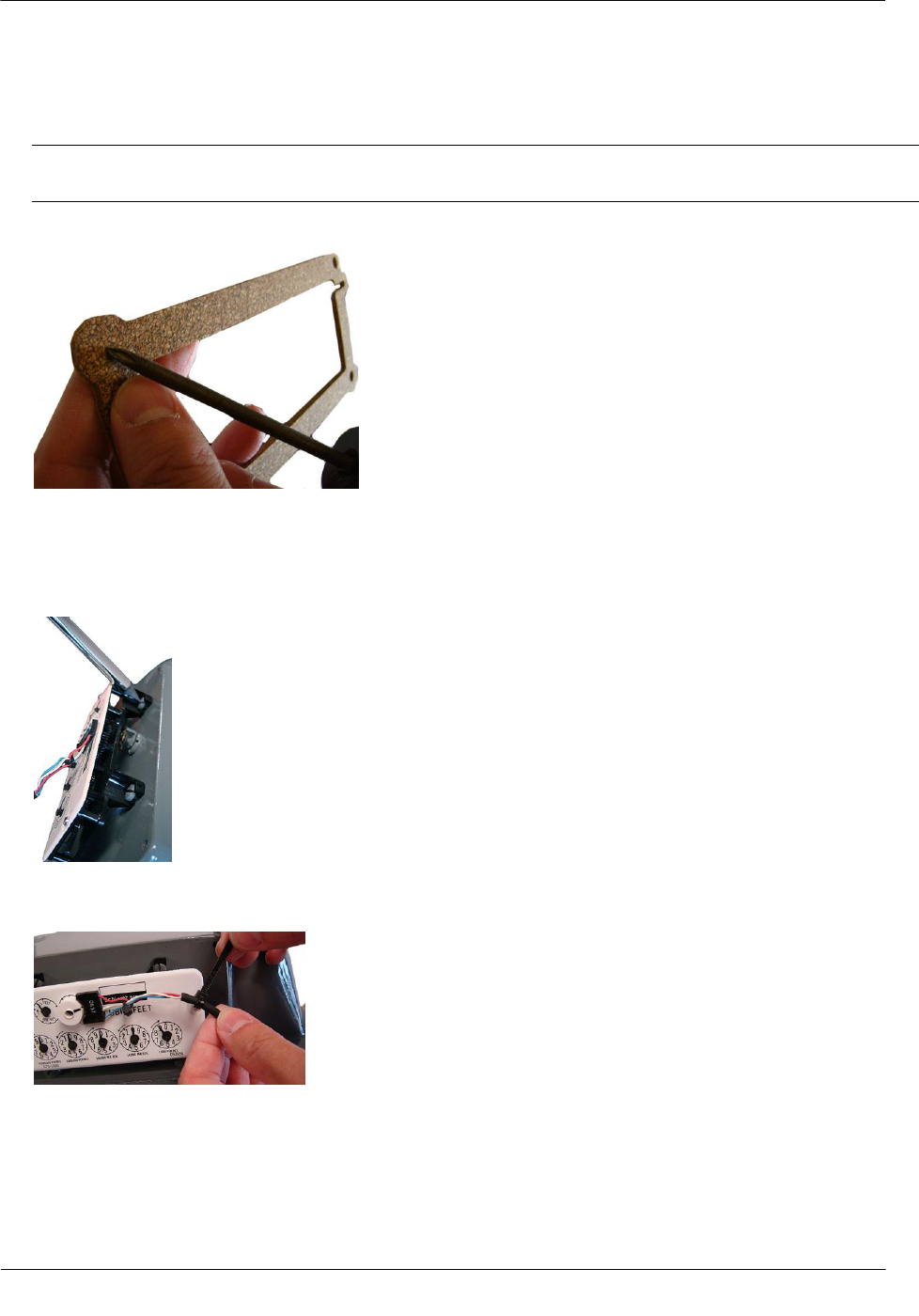
To install the meter index covers over the 2.4GZ OpenWay remote mount gas module
encoder cable
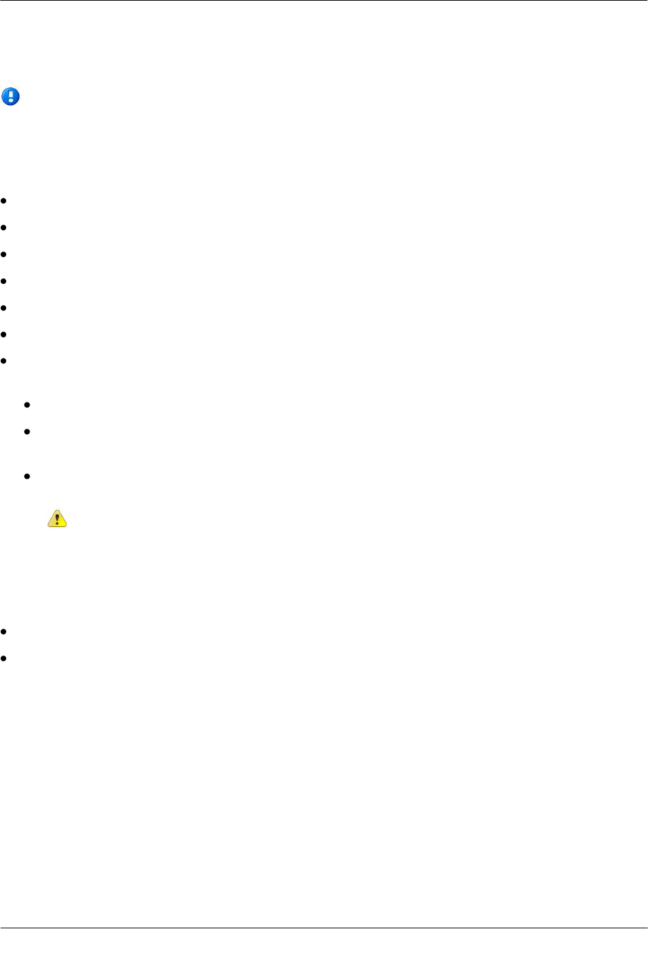
Note Use the correct replacement index cover gasket for your index (see Replacement Gaskets on page
58 for Itron 4-hole, 2-hole, or 1-hole gasket part numbers).
1. Remove the gasket center and index cover hole plugs from the new gasket.
2. Insert the index/encoder assembly through the gasket center. Verify the gasket's adhesive-backed side is
facing the meter face.
3. Align the index wriggler with the meter's drive dog. Install the index on the meter using the index
mounting screws. Tighten in an alternating fashion.
4. Install a strain-relief cable tie about one 1/4" from the encoder cable's stripped end. (The cable tie must be
inside the index cover after the cover is installed on the meter.)
Diaphragm Meter Installation
TDC-0838-001 2.4GZ OpenWay Gas Module Installation Guide - Remote Mount 67
Proprietary and Confidential
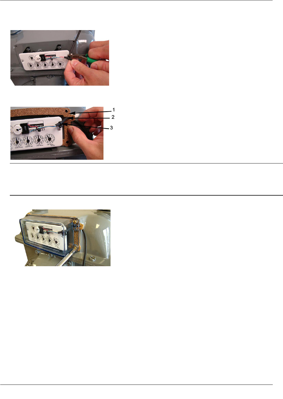
5. Remove the excess cable tie with a side-cutting pliers. Dispose excess cable tie properly.
6. Remove the protective backing on the replacement gasket to expose the adhesive side of the gasket. Align
the gasket (1), encoder cable (2), and cable tie (for strain-relief) (3) on the meter as shown.
Caution Route the encoder cable inside the index cover to provide strain relief (minimize pulling or
twisting on the encoder). Verify the strain-relief cable tie on the encoder cable is inside the index cover
when the cover is installed on the meter. The gasket must align with the index cover screw holes and
adhere to the meter face to insure a proper seal after the index cover is installed.
7. Install the four index cover screws and tighten them just enough to hold them in place.
Diaphragm Meter Installation
TDC-0838-001 2.4GZ OpenWay Gas Module Installation Guide - Remote Mount 68
Proprietary and Confidential
8. Verify the encoder cable is in the cable slot of the gasket. Fully tighten the screws in an alternating
fashion. If required, install utility-approved security wire seals.
2.4GZ OpenWay remote mount gas module encoder/index installation is complete.
Diaphragm Meter Installation
TDC-0838-001 2.4GZ OpenWay Gas Module Installation Guide - Remote Mount 69
Proprietary and Confidential
Programming the 2.4GZ OpenWay Remote Mount Gas Module
Assembly
Caution The 2.4GZ Remote Mount Gas Module must be programmed before use.
Program the 2.4GZ OpenWay remote mount gas module with a Bluetooth-enabled FC200 or FC300 with
SRead handheld computer and ZigBee Belt Clip Radio loaded with Endpoint-Link or Endpoint-Link Pro
software version 5.3.1.26 or version 5.5 for Itron Private Profile (IPP) gas modules (OWG-5001-XXX).
Endpoint-Link Pro software version 5.5 must be used for Smart Energy Profile (SEP) gas modules
(OWG-5002-XXX). See the Endpoint-Link Endpoint Programming Guide (TDC-0744) for more
complete programming information. An Itron magnet is also required for programming.
FC200SR FC300 with SRead Zigbee Belt Clip Radio Itron Magnet
Diaphragm Meter Installation
TDC-0838-001 2.4GZ OpenWay Gas Module Installation Guide - Remote Mount 70
Proprietary and Confidential
To program the 2.4GZ OpenWay remote mount gas module
1. Program the meter drive rate into the 2.4GZ OpenWay remote mount gas module using the handheld
computer and Belt Clip Radio. Programming parameters are based on the configuration file loaded into
the handheld computer.
2. Place the magnet over the barcode on the module cover label with the magnet face (inked Itron logo and
part number) arrow pointed up toward the top of the module.
3. Hold the magnet in place for 5 seconds and remove it.
4. The LED will blink red three times. This signifies the 2.4GZ OpenWay remote mount gas module is
searching for a programming device. Within a few seconds of locating the handheld computer, the red
LED will blink five more times. The handheld computer will confirm programming success or failure.
5. Read the 2.4GZ OpenWay remote mount gas module using the handheld computer and Belt Clip Radio.
If the read result is higher than the number programmed in Step 1, the 2.4GZ OpenWay remote mount
gas module is counting correctly.
If the read result is not higher than the number programmed in Step 1, replace the 2.4GZ OpenWay
remote mount gas module.
TDC-0838-001 2.4GZ OpenWay Gas Module Installation Guide - Remote Mount 71
Proprietary and Confidential
This chapter provides the instructions to install Remote 2.4GZ OpenWay remote mount gas modules (Itron
part number OWG-5001-501 and OWG-5002-501 with 2.5 foot cable and encoder) on curb diaphragm gas
meters where a direct mount endpoint is not possible. Reference the Itron Gas Endpoint Meter Compatibility
List (PUB-0117-002 or the 2.4GZ OpenWay Remote Mount Gas Module Meter Compatibility List on page 3
for compatible curb diaphragm meters.
Materials Available from Itron
The following items are required for each 2.4GZ OpenWay remote mount gas module installation to a curb
diaphragm gas meter:
Itron Part Number
Description
OWG-5001-501
OWG-5002-501
2.4GZ OpenWay Remote Mount Module -
IPP
2.4GZ OpenWay Remote Mount Module -
SEP
CFG-0081-001
Remote Mount Encoder Kit
A Acetone applicator stick
B Tamper Seals
C Cable ties
D Mounting screws
E Hub spacer
F Magnet hub
013-1723-112
Encoder Spacing Tool
(Use the Encoder Spacing Tool to ensure the
encoder mounts the correct distance from the
magnet hub on the meter index.)
CFG-2400-501
American Curb Meter Installation Kit
CH A P T E R 6
Curb Diaphragm Meter Installation
Curb Diaphragm Meter Installation
TDC-0838-001 2.4GZ OpenWay Gas Module Installation Guide - Remote Mount 72
Proprietary and Confidential
Tools and Materials Supplied By You
Note 2.4GZ OpenWay remote mount gas module installation to a curb diaphragm meter may
require additional tools and materials over those listed in Installation Prerequisites on page 7.
The following user/installer-supplied tools and materials are required to install, program, and check the 2.4GZ
OpenWay remote mount gas module:
Medium flat-blade screwdriver
Medium flat-blade, torque-measuring screwdriver
Medium Phillips screwdriver
Pliers
Side-cutting pliers or similar tool
1/4-inch nut driver or other blunt tool for seating endpoint tamper
Itron programming device to program and check 2.4GZ OpenWay remote mount gas module installation
and operation:
FC300 with SRead with Endpoint-Link or Endpoint Link Pro version 5.5 or higher or
FC200 (with Bluetooth-enabled) handheld computer loaded with Endpoint-Link or Endpoint-Link Pro
software to program and check endpoint.
ZigBee Belt-clip Radio with Endpoint-Link or EndPoint-Link Pro software - to program and check
2.4GZ OpenWay remote mount gas module installation and operation.
Caution You must program the 2.4GZ OpenWay remote mount gas module with a Bluetooth-
enabled FC200 or FC300 with SRead handheld computer and ZigBee Belt Clip Radio loaded with
EndPoint-Link Pro software version 5.3.1.26 or version 5.5 for Itron Private Profile (IPP) gas
modules (OWG-5001-XXX).
Endpoint-Link Pro software version 5.5 must be used for Smart Energy Profile (SEP) gas modules
(OWG-5002-XXX).
1-inch putty knife or similar tool to remove old gasket material from the meter and index cover
Replacement temperature compensation (TEMP COMP) meter index stickers (if required)
Curb Diaphragm Meter Installation
TDC-0838-001 2.4GZ OpenWay Gas Module Installation Guide - Remote Mount 73
Proprietary and Confidential
Installing the 2.4GZ Remote Mount Gas Module on the Curb
Meter
The 2.4GZ OpenWay remote mount gas module mounts on a pipe using the Remote Mount Installation Kit
(Itron part number CFG-0005-003) or a vertical flat (wall) surface. Always mount the 2.4GZ OpenWay
remote mount gas module in a vertical position with the arrow pointing down (1), and the encoder wire and
tamper seals (2, 3) at the top, as shown.
Caution Vertical mounting position is important to maximize RF performance. You can mount a
2.4GZ OpenWay remote gas module with the module's label arrow pointing up or down,
dependent upon the application as noted in relevant sections of this installation manual. The
module's arrow must never point to either side. The module's tilt tamper functionality is designed
to operate with the module installed vertically. The 2.4GZ module's tilt tamper will operate with
the label arrow pointed up or down. The module's tilt tamper will not operate with the module
installed horizontally (the label arrow pointed to either side).
Note The occurrence of false tampers may increase on inverted 2.4GZ modules installed in high vibration
areas.
Curb Diaphragm Meter Installation
TDC-0838-001 2.4GZ OpenWay Gas Module Installation Guide - Remote Mount 74
Proprietary and Confidential
To remove the index
Note Properly dispose all unused screws, old index covers, gaskets, tamper seals, and other leftover
materials. Do not leave materials on customer premises. Replace any stripped, worn, or corroded
mounting screws.
1. Cut and remove any wire seal routed through the index cover screws. Remove the index cover and
dispose. Remove the index mounting screws in an alternating fashion.
2. Remove the two index screws in an alternating fashion.
Loosen the left index screw two turns.
Loosen the right index screw three to four turns. Finish removing the index holding screw.
Hold the index while removing the screws to keep the index from falling.
Set the index aside where it will not be damaged.
3. Use the FC200 or FC300 to read the 2.4GZ OpenWay remote mount gas module and record the reading
for comparison with progressive readings as installation is completed.
To install the encoder
1. Take the magnet hub from the Encoder Installation kit (Itron part number CFG-0081-001).
2. Verify there is only one magnet in the hub.
Note If there is no magnet or if there are two magnets in the magnet hub, discard the magnet hub and use
a hub with one magnet.

Curb Diaphragm Meter Installation
TDC-0838-001 2.4GZ OpenWay Gas Module Installation Guide - Remote Mount 75
Proprietary and Confidential
3. Briefly place the magnet side of the magnet hub into the curved indentation in the encoder, as shown.
4. Take the magnet hub away from the encoder and set it at least one inch away from the encoder.
5. Use the FC200 to read the 2.4GZ OpenWay remote mount gas module. If this reading is higher than the
reading taken after removing the index, the 2.4GZ OpenWay remote mount gas module is counting and
working properly.
Note If the reading is not higher than the previous reading, the 2.4GZ OpenWay remote mount gas
module is not reading. Repeat steps 3, 4, and 5. If the 2.4GZ OpenWay remote mount gas module is still
not counting, replace the 2.4GZ OpenWay remote mount gas module and perform steps 3, 4, and 5.
6. Align the large notch in the side of the magnet hub spacer with the needle of the meter drive rate dial (2
foot).
7. Press the magnet hub spacer down over the dial needle as far as possible. The tip on the bottom of the
spacer may touch index face. Turn the dial after hub spacer installation to verify the index dial functions
with a smooth, easy rotation.
Curb Diaphragm Meter Installation
TDC-0838-001 2.4GZ OpenWay Gas Module Installation Guide - Remote Mount 76
Proprietary and Confidential
8. Align the pointer (1) on the top of the magnet hub and the notch (2) in the side of the magnet hub with the
needle (3) of the meter drive rate dial.
9. Press the magnet hub down over the hub spacer as far as possible. The bottom of the hub spacer may
touch the index face. If the tip of the dial needle sticks out past the edge of the magnet hub, cut off the end
of the dial needle as close as possible to the magnet hub with a sharp, side-cutting pliers. Turn the dial
after magnet hub installation to verify the index dial functions with a smooth, easy rotation.
10. Take the acetone stick applicator from the Remote Encoder Installation Kit (Itron part number CFG-0081-
001).
11. Select a location on the index face next to the magnet hub. After encoder installation, the encoder cable
must not interfere with the index dials.
Note If a TEMP COMP sticker is attached to the index where the encoder cable will mount, remove it
before cleaning with the acetone stick. If the sticker (or replacement sticker) must be put back on the
register face, place it in a new location on the index face after the encoder is attached.
12. Tilt the acetone stick vertically with the wick end down. Squeeze the acetone stick on the black dot until
the packet inside the pen breaks. Continue to hold acetone stick vertical until the acetone wicks into the
foam applicator end.
Curb Diaphragm Meter Installation
TDC-0838-001 2.4GZ OpenWay Gas Module Installation Guide - Remote Mount 77
Proprietary and Confidential
13. Thoroughly apply acetone the area where the encoder will be installed. Do not touch the cleaned area of
the index face before the encoder is installed.
14. Slide the thin end of the encoder spacing tool down over the magnet hub.
15. Peel the strip of protective plastic off the adhesive side of the module's encoder.
Curb Diaphragm Meter Installation
TDC-0838-001 2.4GZ OpenWay Gas Module Installation Guide - Remote Mount 78
Proprietary and Confidential
IMPORTANT You must do the next two steps exactly as described or the 2.4GZ OpenWay remote
mount gas module will not work properly.
16. Press the curved side of the encoder firmly against the side of the encoder spacing tool as shown below,
with the adhesive side down.
17. Slide the encoder down along the side of the encoder spacing tool until it touches the surface of the index
(as shown below). Using moderate pressure, hold the encoder firmly against the index, without moving,
for 15 seconds to permanently apply the encoder.
The photo below shows how the encoder spacing tool and encoder will look after the 15 second wait time.
18. Remove the encoder spacing tool, set it aside, and lay the index on a flat, horizontal surface, to diminish
strain on the encoder cable.
Curb Diaphragm Meter Installation
TDC-0838-001 2.4GZ OpenWay Gas Module Installation Guide - Remote Mount 79
Proprietary and Confidential
19. Program the index reading (with the encoder mounted) into the 2.4GZ OpenWay remote mount gas
module.
20. Read the 2.4GZ OpenWay remote mount gas module. If this reading is the same as the reading
programmed into the 2.4GZ OpenWay remote mount gas module, the module is programmed correctly.
To install the meter index covers over the 2.4GZ OpenWay remote mount gas module
encoder cable
1. Align the index wriggler (1) with the meter's drive dog (2). Install the index on the meter using the index
mounting screws. Tighten in an alternating fashion.
2. Install a strain-relief cable tie about one 1/4-inch from the encoder cable's stripped end (1). Remove the
excess cable tie with a side-cutting pliers (2). Dispose the excess cable tie properly.
Curb Diaphragm Meter Installation
TDC-0838-001 2.4GZ OpenWay Gas Module Installation Guide - Remote Mount 80
Proprietary and Confidential
3. Route the encoder cable through the index mounting screw inset to ensure adequate clearance for the
index cover and minimize pulling or twisting on the encoder. Continue routing the cable through the cable
inset on the Itron index cover to provide strain relief. Verify the strain-relief cable tie on the encoder cable
is inside the index cover before tightening the index cover screws.
4. Install the four index cover screws and tighten in an alternating fashion. Install the tamper seals included
in the American Meter Curb Installation kit.
2.4GZ OpenWay remote mount gas module encoder/index installation on the curb meter is complete.

Curb Diaphragm Meter Installation
TDC-0838-001 2.4GZ OpenWay Gas Module Installation Guide - Remote Mount 81
Proprietary and Confidential
Programming the 2.4GZ OpenWay Remote Mount Gas Module
Assembly
Caution The 2.4GZ Remote Mount Gas Module must be programmed before use.
Program the 2.4GZ OpenWay remote mount gas module with a Bluetooth-enabled FC200 or FC300 with
SRead handheld computer and ZigBee Belt Clip Radio loaded with Endpoint-Link or Endpoint-Link Pro
software version 5.3.1.26 or version 5.5 for Itron Private Profile (IPP) gas modules (OWG-5001-XXX).
Endpoint-Link Pro software version 5.5 must be used for Smart Energy Profile (SEP) gas modules
(OWG-5002-XXX). See the Endpoint-Link Endpoint Programming Guide (TDC-0744) for more
complete programming information. An Itron magnet is also required for programming.
FC200SR FC300 with SRead Zigbee Belt Clip Radio Itron Magnet

Curb Diaphragm Meter Installation
TDC-0838-001 2.4GZ OpenWay Gas Module Installation Guide - Remote Mount 82
Proprietary and Confidential
To program the 2.4GZ OpenWay remote mount gas module
1. Program the meter drive rate into the 2.4GZ OpenWay remote mount gas module using the handheld
computer and Belt Clip Radio. Programming parameters are based on the configuration file loaded into
the handheld computer.
2. Place the magnet over the barcode on the module cover label with the magnet face (inked Itron logo and
part number) arrow pointed up toward the top of the module.
3. Hold the magnet in place for 5 seconds and remove it.
4. The LED will blink red three times. This signifies the 2.4GZ OpenWay remote mount gas module is
searching for a programming device. Within a few seconds of locating the handheld computer, the red
LED will blink five more times. The handheld computer will confirm programming success or failure.
5. Read the 2.4GZ OpenWay remote mount gas module using the handheld computer and Belt Clip Radio.
If the read result is higher than the number programmed in Step 1, the 2.4GZ OpenWay remote mount
gas module is counting correctly.
If the read result is not higher than the number programmed in Step 1, replace the 2.4GZ OpenWay
remote mount gas module.
TDC-0838-001 2.4GZ OpenWay Gas Module Installation Guide - Remote Mount 83
Proprietary and Confidential
This section provides the instructions to install the 2.4GZ OpenWay remote mount gas module with Itron
Dattus fM2 and fM3 meters.
Dattus fM2 Dattus fM3
Installation Prerequisites
2.4GZ OpenWay remote mount gas module installation to a Dattus meter requires the following materials:
2.4GZ OpenWay remote mount gas module compatible with the Dattus meter (see the 2.4GZ OpenWay
Remote Mount Gas Module Meter Compatibility List on page 3)
Itron Dattus meter compatible with the 2.4GZ OpenWay remote mount gas module
Tools and devices to complete installation and programming (see Installation Prerequisites on page 7)
Programming the Dattus Meter
Program the Dattus fM2 or fM3 meter with the correct pulse width and weight. For all Dattus type meters, the
pulse width must be set to .050 seconds.
Dattus Meter Pulse Weight Settings
Meter type
Pulse weight in cubic feet (CF)
or cubic meter (CM)
11M or smaller
10 (CF) or 1 CM
16M or greater
100 CF or 1 CM
CH A P T E R 7
Dattus Meter Installation
Dattus Meter Installation
TDC-0838-001 2.4GZ OpenWay Gas Module Installation Guide - Remote Mount 84
Proprietary and Confidential
Installation Overview
Installing the 2.4GZ OpenWay remote mount gas module to an Dattus meter involves five tasks:
1. Programming the meter (reference the Itron Dattus programming guide for more information).
2. Installing any necessary Itron retrofit parts. Itron offers installation kits and brackets for module mounting
options.
3. Mounting the 2.4GZ OpenWay remote mount gas module directly on the meter. If direct-mounting is not
an option for your installation, the 2.4GZ OpenWay remote mount gas module may be mounted on a pipe,
or flat surface (see Mounting the 2.4GZ OpenWay Remote Mount Gas Module on page 8).
4. Connecting the 2.4GZ OpenWay remote mount gas module to the Dattus meter (see Connecting the
2.4GZ OpenWay Remote Mount Gas Module to the Dattus meter on page 87).
5. Programming the 2.4GZ OpenWay Remote Mount Gas Module (see Programming the OpenWay Remote
Mount Gas Module Assembly on page 88).
Installing the 2.4GZ Remote Mount Gas Module to Itron Dattus
Meters
Dattus meters provide an electronic pulse output compatible with the 2.4GZ OpenWay remote mount gas
module. The Dattus meter may be wired to the module using the pulse output cable or the module can be
directly mounted to the meter.
When ordering, customers can have the 2.4GZ OpenWay remote mount gas modules drop shipped to Itron's
Owenton, Kentucky meter factory to have a factory-installed connector attached to the module's bare leads.
The connector directly fits the pulse output on the Dattus meter.
Dattus Meter Installation
TDC-0838-001 2.4GZ OpenWay Gas Module Installation Guide - Remote Mount 85
Proprietary and Confidential
Direct Mounting the 2.4GZ OpenWay Remote Mount Gas
Module to the Dattus Meter
2.4GZ OpenWay remote mount gas modules can be direct mounted to Dattus fM2 and fM3 meters with the
Dattus Direct Mount Kit (Itron part number 442491-001). Dattus meter registers can be rotated to
accommodate vertical or horizontal meter. Customers may have Itron, Owenton, Kentucky complete the cover
modification and bracket attachment or may order the kit to retrofit the Dattus meter. The external cover of the
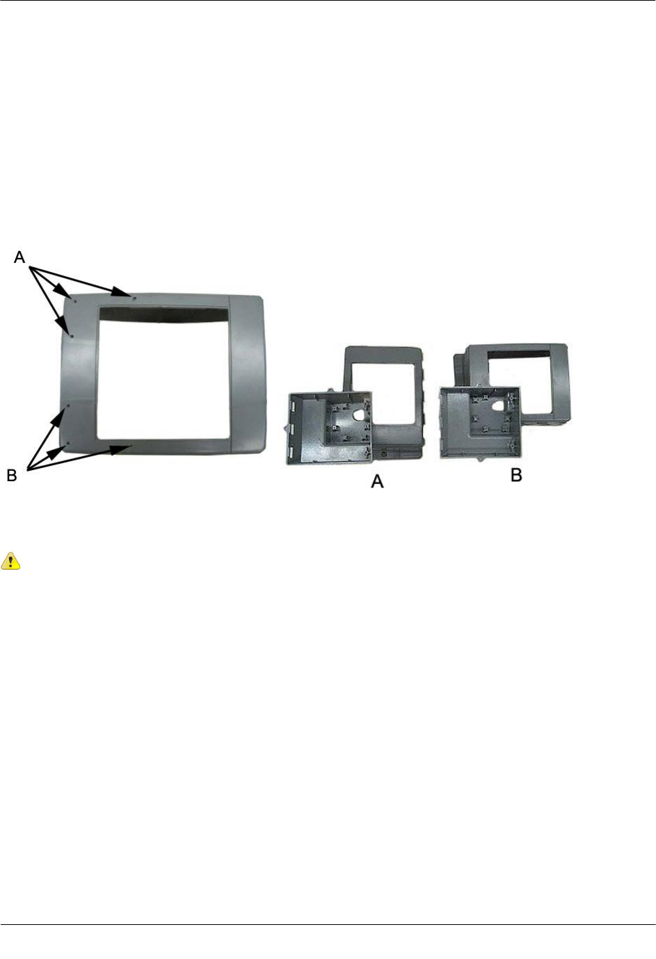
Dattus meter is modified with three holes to mount the module bracket. The modification is dependent on the
orientation of the meter installation.
A
Horizontally oriented meter module mounting hole modifications
B
Vertically oriented meter module mounting hole modifications
Caution Vertical mounting position is important to maximize RF performance. You can mount
a 2.4GZ OpenWay remote gas module with the module's label arrow pointing up or down,
dependent upon the application as noted in relevant sections of this installation manual. The
module's arrow must never point to either side. The module's tilt tamper functionality is
designed to operate with the module installed vertically. The 2.4GZ module's tilt tamper will
operate with the label arrow pointed up or down. The module's tilt tamper will not operate with
the module installed horizontally (the label arrow pointed to either side).
Dattus Meter Installation
TDC-0838-001 2.4GZ OpenWay Gas Module Installation Guide - Remote Mount 86
Proprietary and Confidential
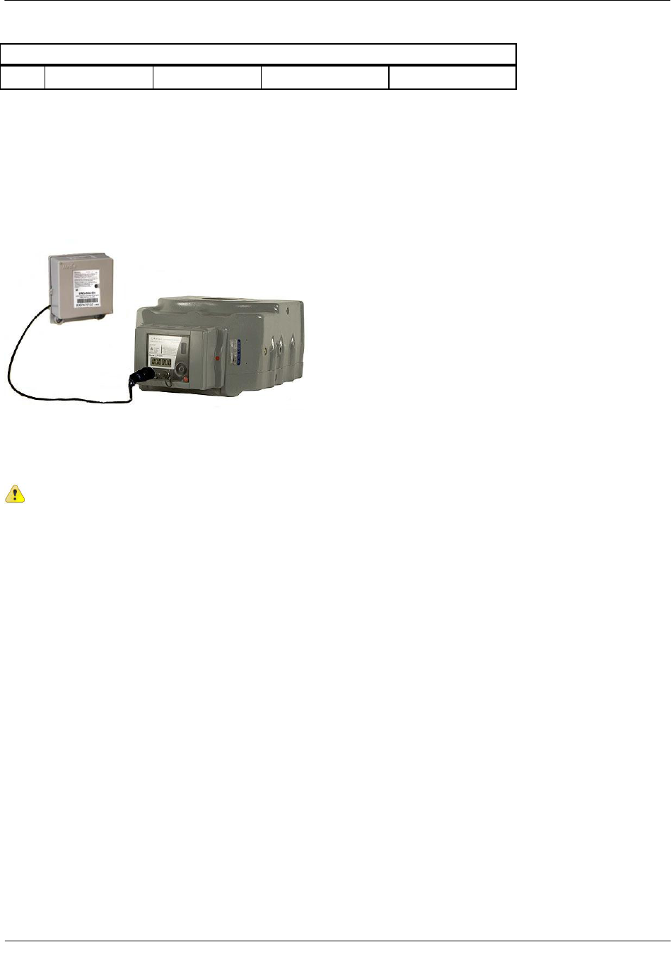
After the meter cover and bracket are replaced on the meter, the 2.4GZ OpenWay remote mount gas module is
connected to the pulse output of the Dattus meter by the Binder Connector. The module is seated into the
bracket to create a secure assembly.
Vertical installation Horizontal installation
Connecting the 2.4GZ OpenWay Remote Mount Gas Module to a
Dattus meter
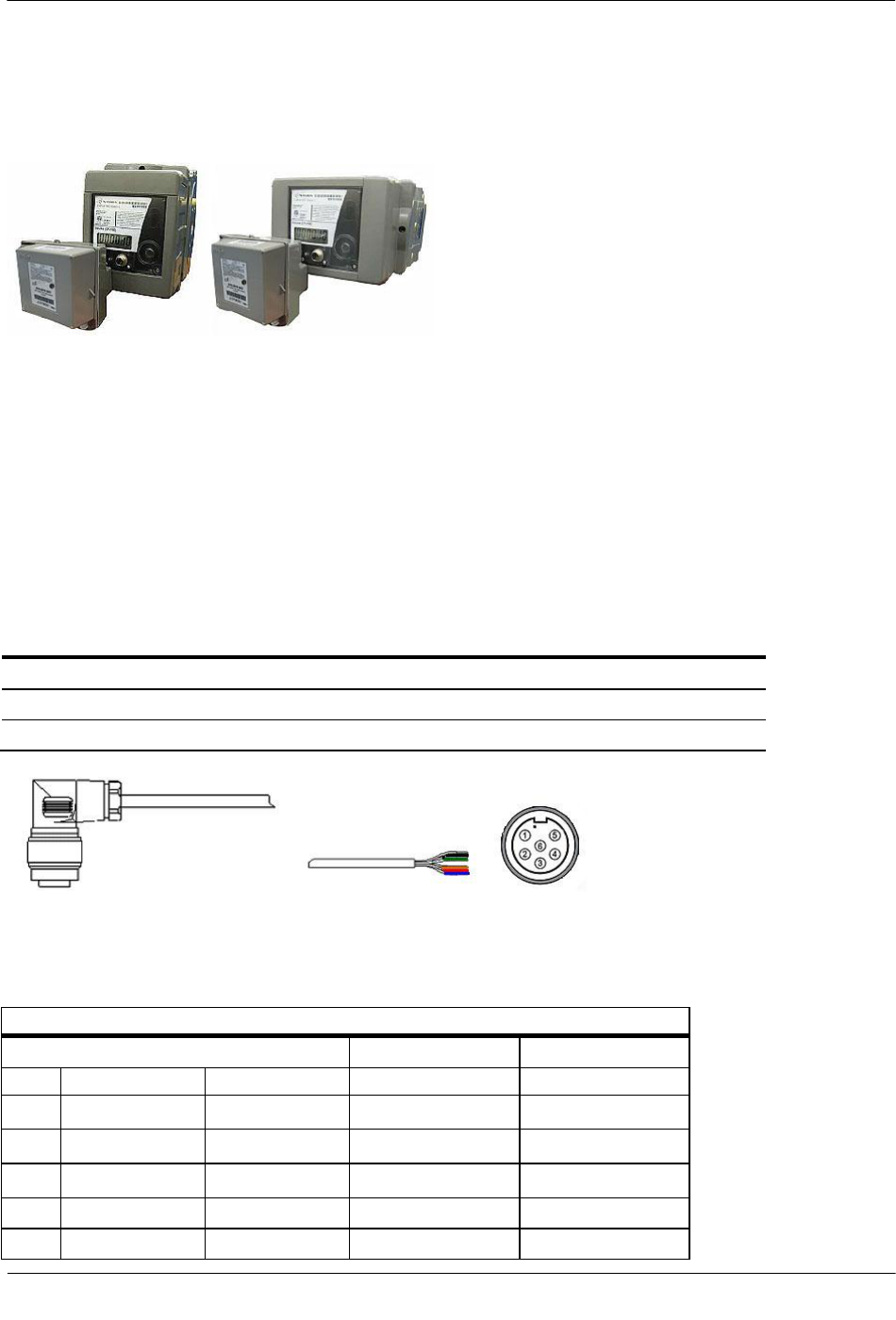
The Dattus fM2 and fM3 meters have two configurable outputs usable as pulse outputs to the 2.4GZ
OpenWay remote mount gas module. Connecting the endpoint following the information in this section
requires a pulse output cable, installed at the Owenton, Kentucky Itron location. Pulse output cables are
available in 10 foot and 20 foot lengths. Factory-installed cables have a Binder connector on one end and six
bare wires on the opposite end.
Dattus Meter Wiring Accessories (available from Itron, Owenton, Kentucky)
Accessory
Itron Part Number
Pulse output cable - 10 ft.
442461-009
Pulse output cable - 20 ft.
442461-010
Pulse output cable
To wire the 2.4GZ to the Dattus meter
Pulse Output Cable Pin Descriptions
To use Output 3
To use Output 4
Pin
Function
Wire color
2.4GZ wire color
2.4GZ wire color
1
Cut cable
White
Blue
2
Output 4 (+)
Black
White
3
Ground (-)
Green
Red
4
Output 3 (+)
Orange
White
5
Cut cable
Red
Blue
Dattus Meter Installation
TDC-0838-001 2.4GZ OpenWay Gas Module Installation Guide - Remote Mount 87
Proprietary and Confidential
Pulse Output Cable Pin Descriptions
6
Ground (-)
Blue
Red
Mounting the 2.4GZ OpenWay Remote Mount Gas Module
The 2.4GZ OpenWay remote mount gas module can be mounted on a pipe or vertical flat surface (wall).
Mounting requires the Itron Remote Mount Kit (Itron part number CFG-0005-003). See Mounting the 2.4GZ
OpenWay Remote Mount Gas Module on page 8 for mounting procedure instructions.
Programming the 2.4GZ OpenWay Remote Mount Gas Module
Assembly
Caution The 2.4GZ Remote Mount Gas Module must be programmed before use.
Dattus Meter Installation
TDC-0838-001 2.4GZ OpenWay Gas Module Installation Guide - Remote Mount 88
Proprietary and Confidential
Program the 2.4GZ OpenWay remote mount gas module with a Bluetooth-enabled FC200 or FC300 with
SRead handheld computer and ZigBee Belt Clip Radio loaded with Endpoint-Link or Endpoint-Link Pro
software version 5.3.1.26 or version 5.5 for Itron Private Profile (IPP) gas modules (OWG-5001-XXX).
Endpoint-Link Pro software version 5.5 must be used for Smart Energy Profile (SEP) gas modules
(OWG-5002-XXX). See the Endpoint-Link Endpoint Programming Guide (TDC-0744) for more
complete programming information. An Itron magnet is also required for programming.
FC200SR FC300 with SRead Zigbee Belt Clip Radio Itron Magnet
To program the 2.4GZ OpenWay remote mount gas module
1. Program the meter drive rate into the 2.4GZ OpenWay remote mount gas module using the handheld
computer and Belt Clip Radio. Programming parameters are based on the configuration file loaded into
the handheld computer.
2. Place the magnet over the barcode on the module cover label with the magnet face (inked Itron logo and
part number) arrow pointed up toward the top of the module.
3. Hold the magnet in place for 5 seconds and remove it.
Dattus Meter Installation
TDC-0838-001 2.4GZ OpenWay Gas Module Installation Guide - Remote Mount 89
Proprietary and Confidential
4. The LED will blink red three times. This signifies the 2.4GZ OpenWay remote mount gas module is
searching for a programming device. Within a few seconds of locating the handheld computer, the red
LED will blink five more times. The handheld computer will confirm programming success or failure.
5. Read the 2.4GZ OpenWay remote mount gas module using the handheld computer and Belt Clip Radio.
If the read result is higher than the number programmed in Step 1, the 2.4GZ OpenWay remote mount
gas module is counting correctly.
If the read result is not higher than the number programmed in Step 1, replace the 2.4GZ OpenWay
remote mount gas module.
TDC-0838-001 2.4GZ OpenWay Gas Module Installation Guide - Remote Mount 90
Proprietary and Confidential
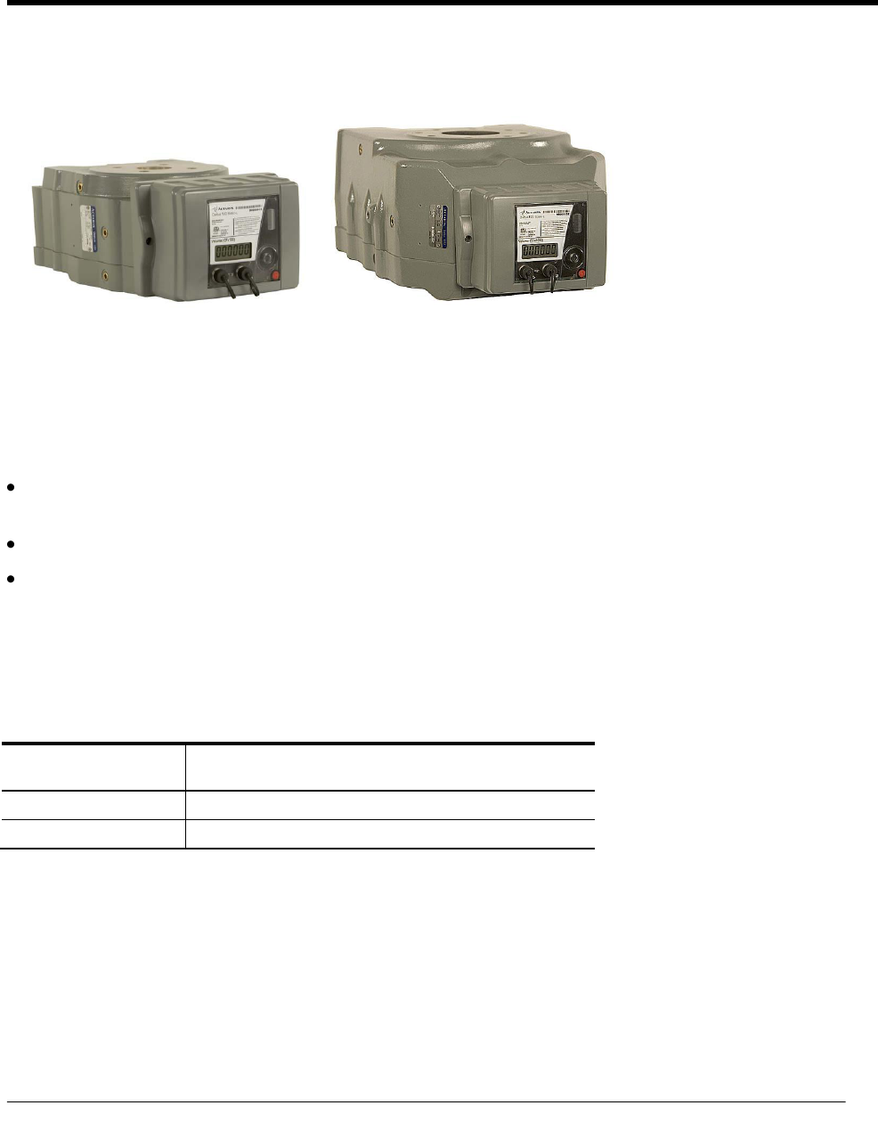
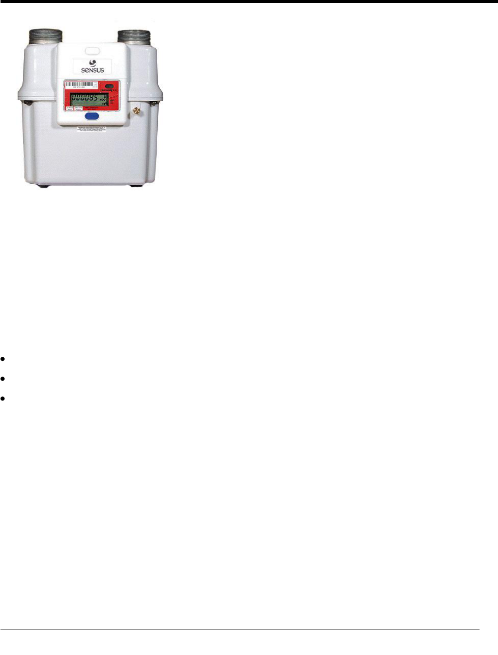
Sensus Sonix Meter
Programming the Sensus Sonix Meter
Program the Sensus Sonix meter following the Sensus programming guidelines.
Adjusting the Pulse Output for Sonix 600 and 880 Meters
The pulse output sent to the 2.4GZ OpenWay remote mount gas module may be set (using the SonixCom
software) as:
1 pulse per 10 cf
1 pulse per 100 cf
1 pulse per 1000 cf
Contact Sensus North American Gas Customer Service for more information.
CH A P T E R 8
Sensus Sonix Meter Installation
Sensus Sonix Meter Installation
TDC-0838-001 2.4GZ OpenWay Gas Module Installation Guide - Remote Mount 91
Proprietary and Confidential
Installing the 2.4GZ OpenWay Remote Mount Gas Module with
Sensus Sonix Meters
Sensus Sonix meters provide a standard Form A electronic pulse output compatible with the 2.4GZ OpenWay
remote mount gas module. The Sensus Sonix meter may be connected to the module using the pulse output
cable or the module can be directly mounted to the meter.
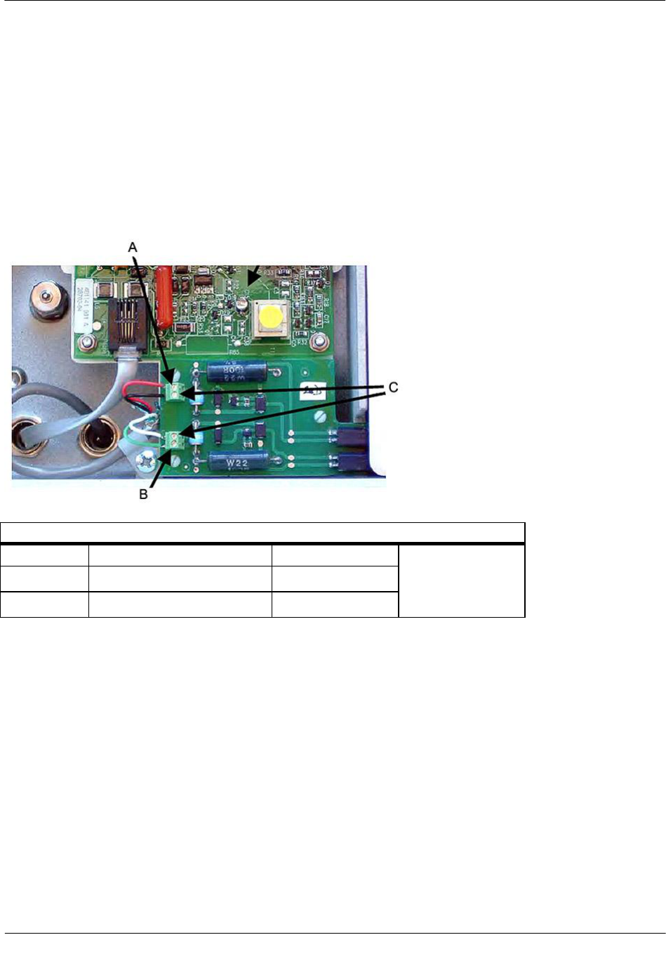
Sensus Sonix2000 Pulse Output Wiring
Sensus Sonix2000 Pulse Output Options
Option
(A) Pulse 1 (+)
(B) Pulse 2 (+)
(C) Ground (-)
1
Uncorrected
Corrected
2
LCD index volume
Alarm
Sensus Sonix Meter Installation
TDC-0838-001 2.4GZ OpenWay Gas Module Installation Guide - Remote Mount 92
Proprietary and Confidential
Direct Mounting the 2.4GZ OpenWay Remote Mount Gas Module to the
Sonix Meter
2.4GZ OpenWay remote mount gas modules can be direct mounted to Sensus Sonix meters at the Sensus
factory (contact Sensus North American Gas Customer Service for mounting specifications and ordering
information). This section includes the instructions for customers to mount the moduleon the Sonix meter
using the mounting materials available from Sensus Metering Systems.
A
Top anchor screw positions
B
Bottom anchor position for the endpoint U-shaped mount
Sensus Sonix Direct Mount Brackets and Mounting Hardware
Sensus Part Number
Description
60025-063-00000
1 1/2" FTP, 45Lt, #3 Spg, 60Lt, #4 Spg
60025-063-01000
2" - 11BS, 2" FTP
60025-063-02000
30Lt, #1A Spg, 1 1/4" NPT, #2 Spg, 20Lt
903376
#8-32 x 3/4" SS Fillister-head screws (2 required)
011-14-286-00
Rubber mounting washer
Stabilizes bracket/2.4GZ OpenWay remote mount gas module assembly
*Order the correct bracket for your installation requirements from Sensus North American Gas Customer
Service. Brackets and mounting hardware are ordered separately.
Sensus Sonix Meter Installation
TDC-0838-001 2.4GZ OpenWay Gas Module Installation Guide - Remote Mount 93
Proprietary and Confidential
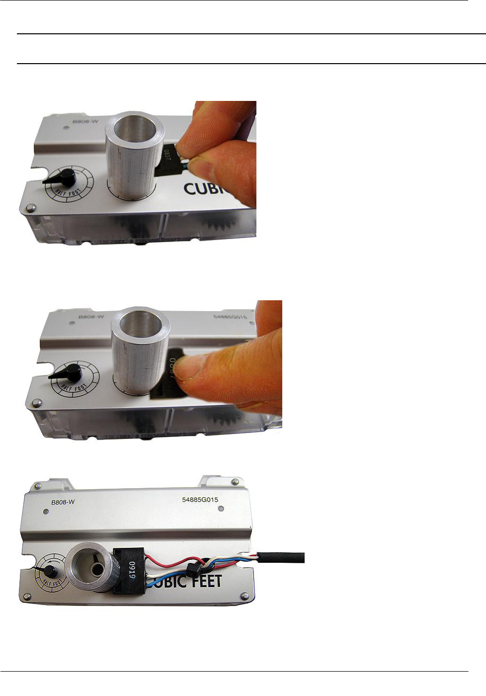
To direct-mount the 2.4GZ OpenWay remote mount gas module on the Sonix meter
1. Place the module mounting bracket over the inlet or outlet pipe fitting on the Sonix meter. (The default
position is over the inlet connection - left side connection looking at the meter front.)
2. Remove the four module backplate screws and turn the backplate so the module mounting screw holes are
to the top of the module (the arrow on the module label must point up). Secure with the four module
backplate screws previously removed.
3. Slide the mounting lug (now on the bottom of the module) over the bottom anchor. Insert the two top
module mounting screws and tighten in an alternating fashion.
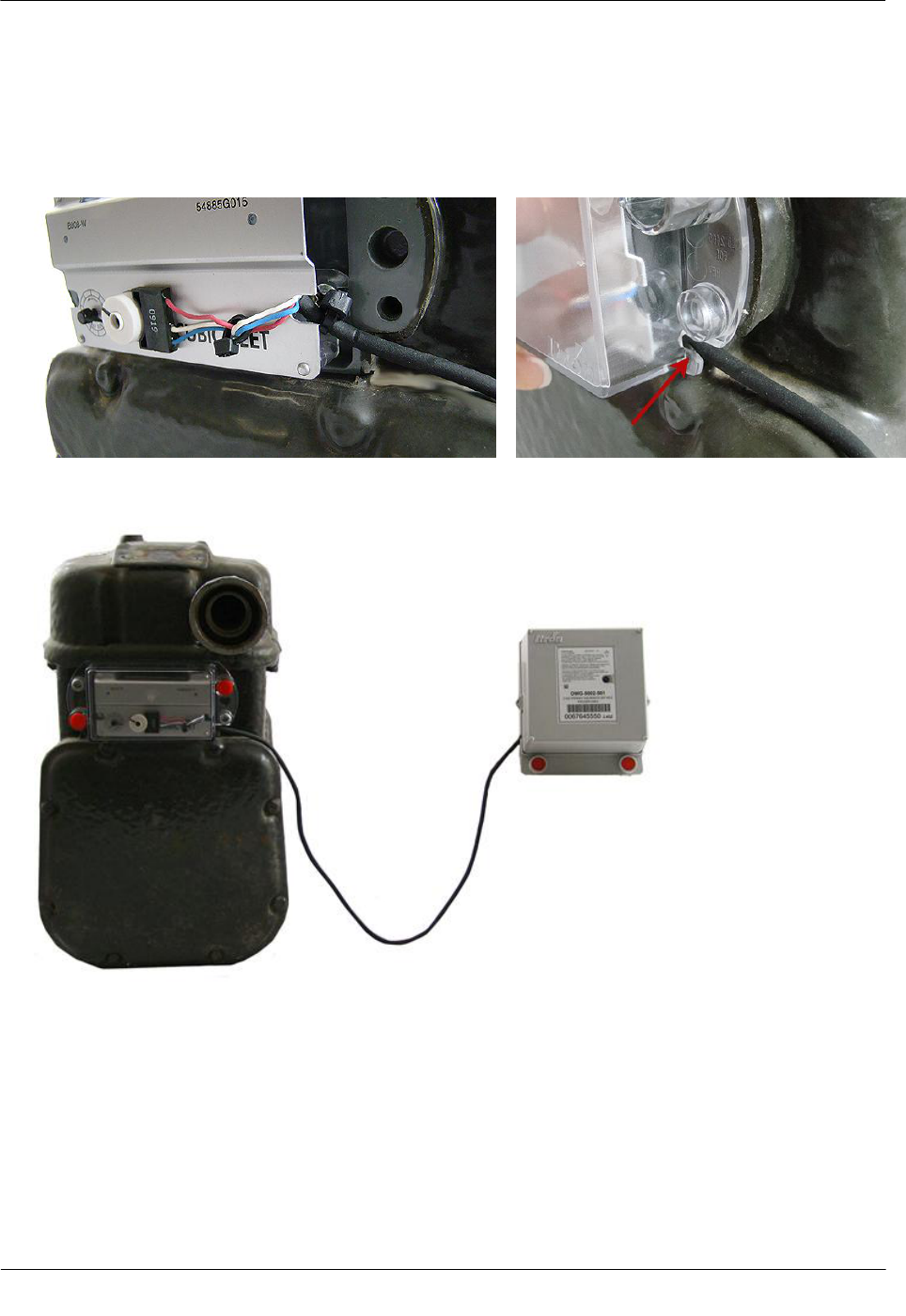
Connecting the 2.4GZ OpenWay Remote Mount Gas Module to a Sensus
Sonix 600 or 880 Meter
The 2.4GZ OpenWay remote mount gas module provides RF-based data collection for the Sonix 600 or 880
meter.
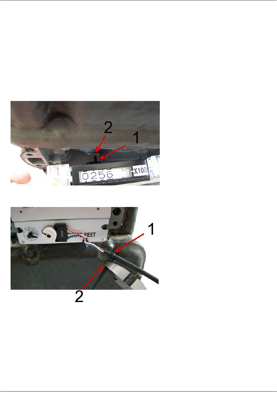
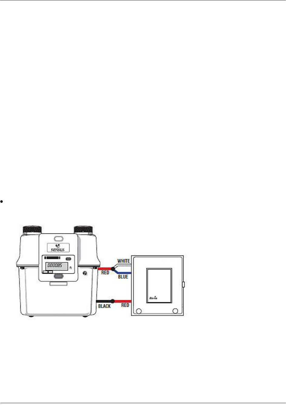
To wire the 2.4GZ OpenWay remote mount gas module to Sonix 600 and 880 meters
Connect the Sonix 600 or 880 meter to the 2.4GZ OpenWay remote mount gas module following the
wiring diagram below.
Sensus Sonix Meter Installation
TDC-0838-001 2.4GZ OpenWay Gas Module Installation Guide - Remote Mount 94
Proprietary and Confidential
Programming the 2.4GZ OpenWay Remote Mount Gas Module
Assembly
Caution The 2.4GZ Remote Mount Gas Module must be programmed before use.
Program the 2.4GZ OpenWay remote mount gas module with a Bluetooth-enabled FC200 or FC300 with
SRead handheld computer and ZigBee Belt Clip Radio loaded with Endpoint-Link or Endpoint-Link Pro
software version 5.3.1.26 or version 5.5 for Itron Private Profile (IPP) gas modules (OWG-5001-XXX).
Endpoint-Link Pro software version 5.5 must be used for Smart Energy Profile (SEP) gas modules
(OWG-5002-XXX). See the Endpoint-Link Endpoint Programming Guide (TDC-0744) for more
complete programming information. An Itron magnet is also required for programming.
FC200SR FC300 with SRead Zigbee Belt Clip Radio Itron Magnet
Sensus Sonix Meter Installation
TDC-0838-001 2.4GZ OpenWay Gas Module Installation Guide - Remote Mount 95
Proprietary and Confidential
To program the 2.4GZ OpenWay remote mount gas module
1. Program the meter drive rate into the 2.4GZ OpenWay remote mount gas module using the handheld
computer and Belt Clip Radio. Programming parameters are based on the configuration file loaded into
the handheld computer.
2. Place the magnet over the barcode on the module cover label with the magnet face (inked Itron logo and
part number) arrow pointed up toward the top of the module.
3. Hold the magnet in place for 5 seconds and remove it.
4. The LED will blink red three times. This signifies the 2.4GZ OpenWay remote mount gas module is
searching for a programming device. Within a few seconds of locating the handheld computer, the red
LED will blink five more times. The handheld computer will confirm programming success or failure.
5. Read the 2.4GZ OpenWay remote mount gas module using the handheld computer and Belt Clip Radio.
If the read result is higher than the number programmed in Step 1, the 2.4GZ OpenWay remote mount
gas module is counting correctly.
If the read result is not higher than the number programmed in Step 1, replace the 2.4GZ OpenWay
remote mount gas module.

TDC-0838-001 2.4GZ OpenWay Gas Module Installation Guide - Remote Mount 96
Proprietary and Confidential
Symbols & Numbers
2.4GZ OpenWay Remote Mount Gas Module
Meter Compatibility List • 83, 71, 57, 37, 3
2.4GZ Remote Mount Gas Module Installation • 1
A
Adapter Plate Mounting Positions • 13
B
Before You Begin • v
C
Code Settings • 38, 40, 40, 42
Connecting the 2.4GZ OpenWay Remote Mount
Gas Module to the IMC/W2 or MC2 Cable • 48
Connecting the 2.4GZ OpenWay Remote Mount
Gas Module to the Rotary Meter Cable • 20
Connecting the 2.4GZ OpenWay Remote Mount
Gas Module to a Dattus meter • 86
Connecting the 2.4GZ OpenWay Remote Mount
Gas Module to a Sensus Sonix 600 or 880 Meter
• 93
Connecting the 2.4GZ OpenWay Remote Mount
Gas Module to the Romet ECM2® Meter • 31
D
Dattus Meter Installation • 83
Diaphragm Meter Installation • 57, 71
Direct Mounting the 2.4GZ OpenWay Remote
Mount Gas Module to the Sonix Meter • 92
Direct Mounting the 2.4GZ OpenWay Remote
Mount Gas Module to the Dattus Meter • 85
I
Installation Options • 8
Installation Overview • 37, 84
Installation Prerequisites • 7, 28, 37, 57, 72, 83
Installing 2.4GZ OpenWay Remote Mount Gas
Module Encoders • 60
Installing the 2.4GZ OpenWay Remote Mount Gas
Module • 59
Installing the 2.4GZ OpenWay Remote Mount Gas
Module to the Elster American Meter RPM
Series Rotary Meter • 25
Installing the 2.4GZ OpenWay Remote Mount Gas
Module to the Romet Electronically
Compensated Meter (ECM2® ) • 30
Installing the 2.4GZ OpenWay Remote Mount Gas
Module with Sensus Sonix Meters • 91
Installing the 2.4GZ Remote Mount Gas Module
on the Curb Meter • 73
Installing the 2.4GZ Remote Mount Gas Module
to Itron Dattus Meters • 84
Installing the Endpoint to the Dresser ROOTS®
Micro Corrector (IMC/W2 or MC2) • 51
M
Materials Available from Itron • 58, 71
Mercury Electronic Volume Corrector Installation
• 36
Mounting Installation Considerations • 9
Mounting Screw Specifications • 8
Mounting the 2.4GZ OpenWay Remote Mount
Gas Module on a Pipe • 30, 10
Mounting the 2.4GZ OpenWay Remote Mount
Gas Module • 87, 84, 41, 37, Error! Bookmark
not defined., 22, 8
Mounting the 2.4GZ OpenWay Remote Mount
Gas Module • 30
Mounting the Endpoint on a Wall or Other Flat
Vertical Surface • 16
P
Programming 2.4GZ OpenWay Remote Mount
Gas Module for Dresser ROOTS® Rotary
Meters • 24
Programming Modes • 2
Programming the 2.4GZ OpenWay Remote Mount
Gas Module Assembly • 94, 87, 81, 69, 55, 34
Programming the Dattus Meter • 83
Programming the Mercury Instrument • 38
Programming the Sensus Sonix Meter • 90
R
Related Documents • 3, 19
Replacement Gaskets • 58, 66
Required Installation Materials Available from
Itron • 20
Romet ECM2 Mounting Requirement • 31
Rotary Meter Installation • 19
Index

TDC-0838-001 2.4GZ OpenWay Gas Module Installation Guide - Remote Mount 97
Proprietary and Confidential
S
Sensus Sonix Meter Installation • 90
Specifications • 3
T
To attach the endpoint to the IMC\W2 and MC2 •
52
To connect the 2.4GZ OpenWay remote mount gas
module cable assembly to the rotary meter • 23
To connect the 2.4GZ OpenWay remote mount gas
module to the IMC/W2 or MC2 cable • 48
To connect the 2.4GZ OpenWay remote mount gas
module to the rotary meter cable • 21
To connect the manufacturer cable to the endpoint
• 27
To install dual 2.4GZ OpenWay remote mount gas
modules to a Mercury Instrument Mini-Max
Case Corrector using Mercury Kit 22-1077 • 42
To install tamper seals and cable ties • 15, 17
To install the 2.4GZ OpenWay remote mount gas
module cable • 29
To install the 2.4GZ OpenWay remote mount gas
module on an Elster American RPM series
meter • 26
To install the encoder • 61, 74
To install the meter index covers over the 2.4GZ
OpenWay remote mount gas module encoder
cable • 79, 66
To make TCI pulse connections • 46
To mount the 2.4GZ OpenWay remote mount gas
module on a wall or other flat vertical surface •
16
To mount the 2.4GZ OpenWay remote mount gas
module on the adapter plate • 13
To mount the 2.4GZ OpenWay remote mount gas
module on the Romet ECM2 meter • 32
To mount the adapter plate on the pipe bracket •
12
To mount the pipe bracket on a vertical pipe • 11
To program the 2.4GZ OpenWay remote mount
gas module • 95, 88, 82, 70, 56, 35
To remove the index • 60, 74
To wire the 2.4GZ OpenWay remote mount gas
module to Sonix 600 and 880 meters • 93
To wire the 2.4GZ OpenWay remote mount gas
module to the Mercury Instrument corrector • 41
To wire the 2.4GZ to the Dattus meter • 86
Tools and Materials Supplied By You • 57, 72
Transmission Modes • 1
W
Wiring Dual Endpoints to a Mercury Instrument
Corrector • 42
Wiring the 2.4GZ OpenWay Remote Mount Gas
Module to the Mercury Instrument • 40, 37
Wiring the Remote Endpoint to the Mercury TCI •
44