Itron 920 Gateway User Manual
Silver Spring Networks Gateway
UserManual.wiki
>
Itron
>
920 User Manual
>
User Manual
Contents
1.
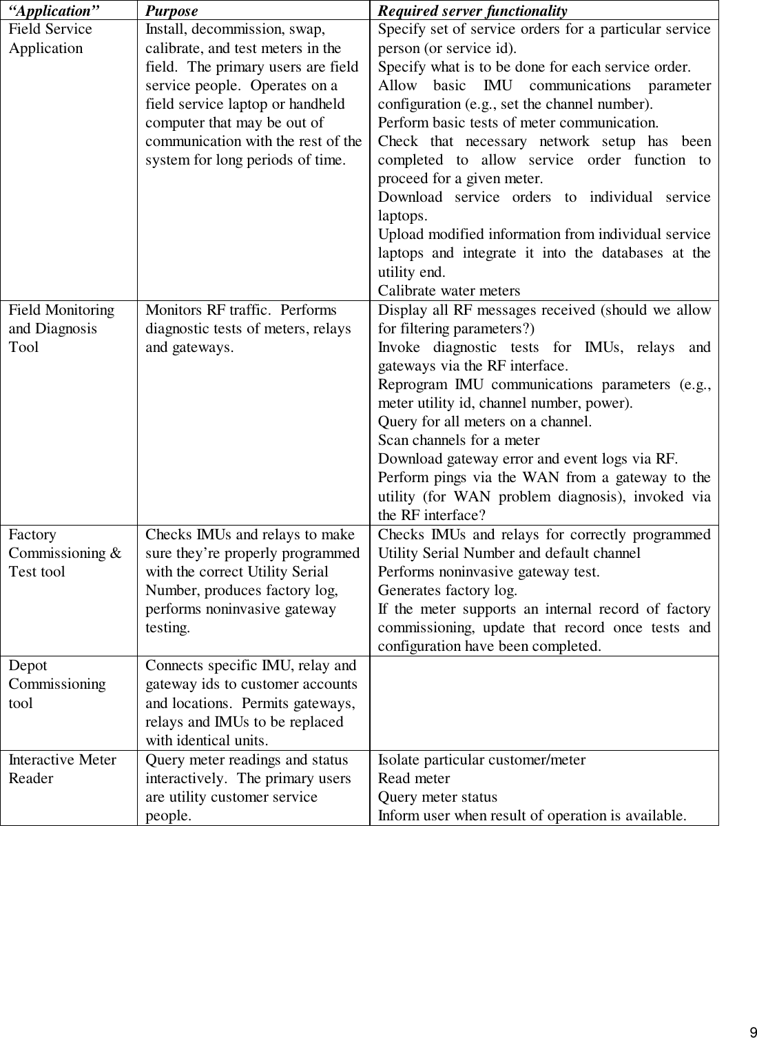
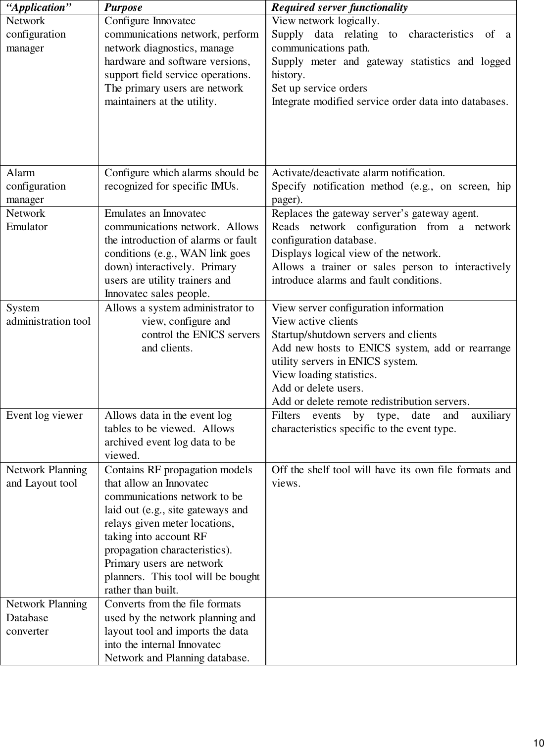
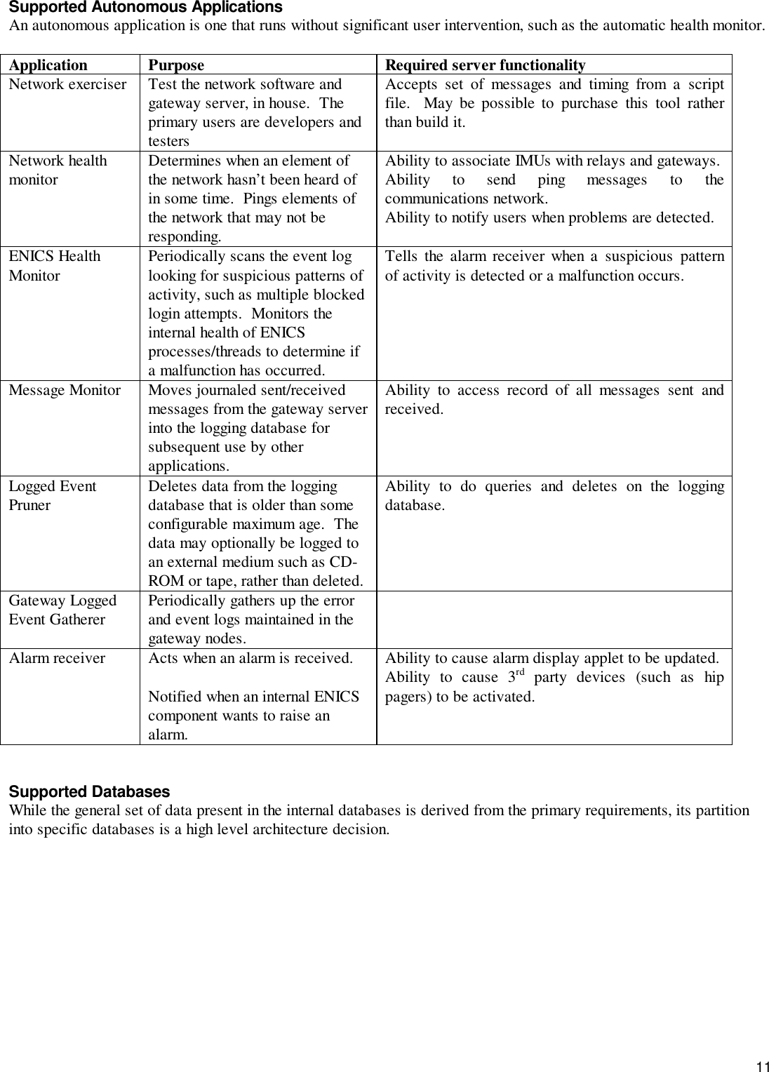
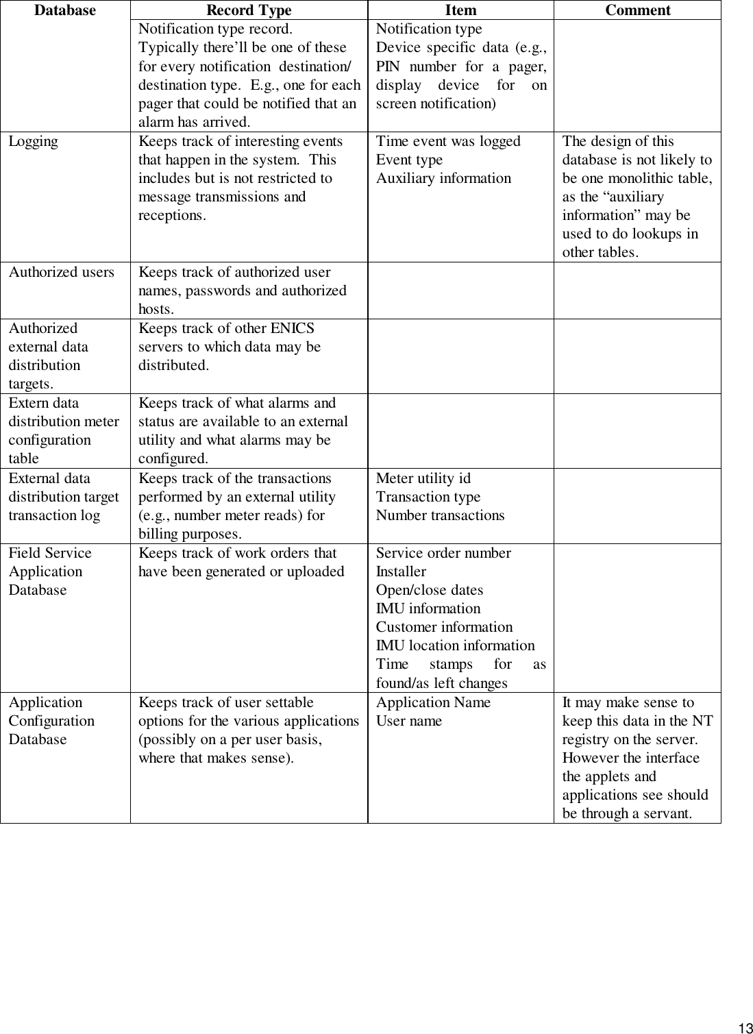
User Manual
2.
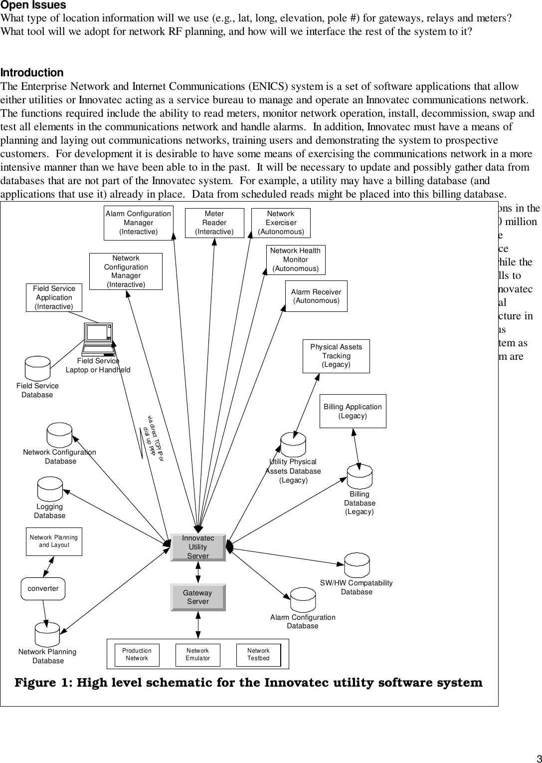
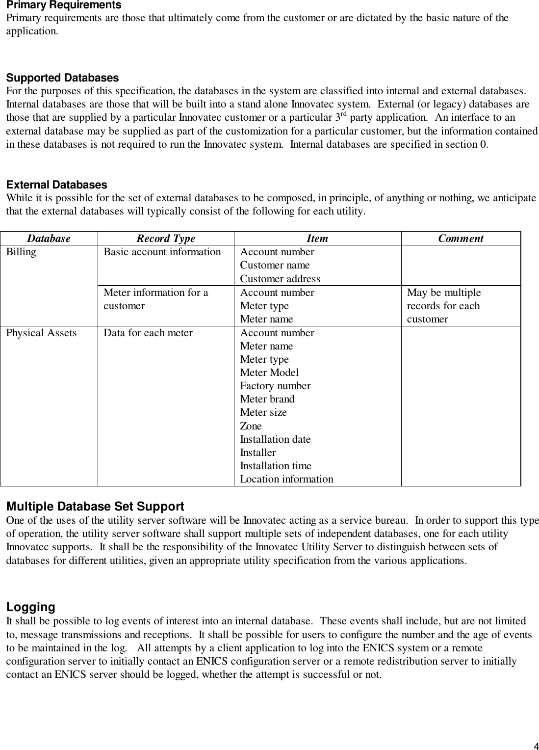
Operational Instructions(ulitlity software....?)
User Manual
Navigation menu
Upload a User Manual
Namespaces
Wiki Guide
HTML
PDF
Info
Views
User Manual
Discussion / Help
Navigation