Itron 921 Gateway/Telco User Manual Utility Network Operational Manual
Silver Spring Networks Gateway/Telco Utility Network Operational Manual
Itron >
Contents
- 1. User Manual
- 2. Utility Network Operational Manual
- 3. Modem User Manual
Utility Network Operational Manual

Innovatec Utility Software System Organization and
Requirements
Compuware Corp.
08/09/99 11:13 AM06/16/99 2:46 PM
Version 0.32

2
Table of Contents
1 OPEN ISSUES...............................................................................................................................4
2 INTRODUCTION.........................................................................................................................4
3 PRIMARY REQUIREMENTS....................................................................................................5
3.1 SUPPORTED DATABASES..........................................................................................................6
3.1.1 External databases..........................................................................................................6
3.2 MULTIPLE DATABASE SET SUPPORT .........................................................................................6
3.3 LOGGING..................................................................................................................................7
3.4 ARCHITECTURAL CONSTRAINTS...............................................................................................7
3.5 SERVER DATA MAINTENANCE ..................................................................................................7
3.6 EXTERNAL DATA DISTRIBUTION .............................................................................................7
3.7 SECURITY.................................................................................................................................8
3.7.1 Firewalls .........................................................................................................................9
3.7.2 Attack methods ................................................................................................................9
3.7.3 Export restrictions.........................................................................................................11
3.8 INTERNATIONALIZATION........................................................................................................11
3.9 FACTORY/DEPOT/INSTALLATION WORK FLOW .....................................................................11
4 DERIVED REQUIREMENTS ..................................................................................................13
4.1 SUPPORTED APPLICATIONS ....................................................................................................13
4.1.1 Supported interactive applications ...............................................................................13
4.1.2 Supported autonomous applications.............................................................................16
4.2 SUPPORTED DATABASES........................................................................................................18
4.2.1 Internal databases.........................................................................................................18
4.3 COM ACCESS ....................................................................................................................2221
4.4 REQUIRED REQUIREMENTS ................................................................................................2221
4.5 INNOVATEC LOOK AND FEEL.............................................................................................2221
4.5.1 Pluggable Look and Feel ..........................................................................................2221
4.5.2 Colors........................................................................................................................2322
4.5.2.1 Foreground/Text.....................................................................................................2322
4.5.2.2 Background............................................................................................................2322
4.6 NAVIGATION ......................................................................................................................2322
4.6.1 Keyboard ...................................................................................................................2322
4.6.1.1 Mnemonics ............................................................................................................2322
4.6.1.2 Shortcuts................................................................................................................2423
4.6.2 Mouse ........................................................................................................................2423
4.7 COMPONENTS.........................................................................................................................24
4.7.1 Primary Windows..........................................................................................................24
4.7.2 Secondary Windows ..................................................................................................2524
4.7.2.1 Dialogs ..................................................................................................................2524
4.7.2.2 Login Dialog ..........................................................................................................2524
4.7.3 Plain Windows...........................................................................................................2524
4.7.3.1 Splash Screens........................................................................................................2524
4.7.4 A splash screen should be implemented using com.innovatec.ui.Jsplash. The
application name, version and copyright information should appear on all splash screens.Applets
..........................................................................................................................................................2625
4.7.5 Buttons.......................................................................................................................2625
4.7.5.1 Toolbars.................................................................................................................... 26
4.7.6 Menus ............................................................................................................................26
4.7.7 Statusbar .......................................................................................................................26
4.7.8 Organizing.................................................................................................................2726
4.7.8.1 Group Boxes ..........................................................................................................2726

3
4.7.8.2 Tabbed Panes.........................................................................................................2726
5 CHANGE LOG ...........................................................................................................................27
4
1 Open Issues
• What type of location information will we use (e.g., lat, long,
elevation, pole #) for gateways, relays and meters?
• What tool will we adopt for network RF planning, and how will
we interface the rest of the system to it?
2 Introduction
The Enterprise Network and Internet Communications (ENICS)
system is a set of software applications that allow either utilities or
Innovatec acting as a service bureau to manage and operate an Innovatec
communications network. The functions required include the ability to
read meters, monitor network operation, install, decommission, swap
and test all elements in the communications network and handle alarms.
In addition, Innovatec must have a means of planning and laying out
communications networks, training users and demonstrating the system
to prospective customers. For development it is desirable to have some
means of exercising the communications network in a more intensive
manner than we have been able to in the past.
It will be necessary to update and possibly gather data from
databases that are not part of the Innovatec system. For example, a
utility may have a billing database (and applications that use it) already
in place. Data from scheduled reads might be placed into this billing
database.
Finally, it should be possible to log events of interest for later
analysis either by utility personnel or applications in the Innovatec
system.
Innovatec plans to eventually use the system for very large
installations (on the order of 10 million meters or more). Thus, it is
necessary to architect and build the system in such a way that its
functions can be distributed across multiple machines and possibly
multiple servers.
In addition, in Innovatec’s role as a service bureau, it may be
necessary to site a gateway server and possibly some server functions at
a customer site, while the rest are handled at Innovatec’s offices. For
example, a utility may want to put modems at their site so that calls to
gateways are local calls, while Innovatec administers the network
remotely.
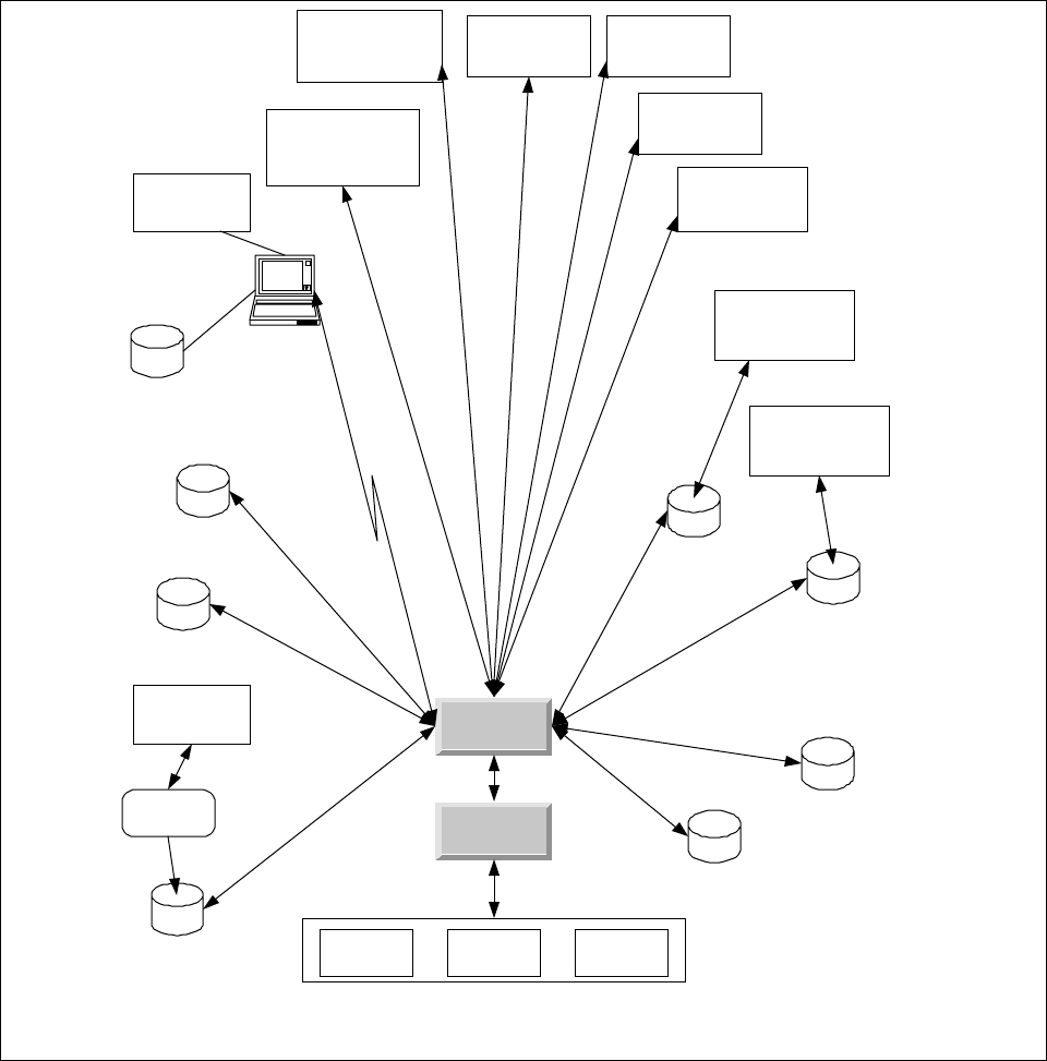
A high level schematic for the Innovatec utility system is shown in
Figure 1. In the schematic, each of the applications is shown as if it was
a traditional monolithic program. However, the Innovatec system is
being designed and implemented as a multitier architecture in which the
user interface is a set of Java applets and HTML pages which use a set of
servants to access various services, such as database access.
5
This document supplies a general organization and partitioning for
the system as well as requirements that apply to all applications. The
requirements for the various components of the system are contained in
their own requirements documents.
3 Primary Requirements
Primary requirements are those that ultimately come from the
customer or are dictated by the basic nature of the application.
Network Configuration
Database
SW/HW Compatability
Database
Network Planning
Database
Alarm Configuration
Database
Logging
Database
Billing
Database
(Legacy)
Utility Physical
Assets Database
(Legacy)
Gateway
Server
Innovatec
Utility
Server
Production
Network Network
Emulator Network
Testbed
Field Service
Application
(Interactive)
Network
Configuration
Manager
(Interactive)
Alarm Configuration
Manager
(Interactive)
Field Service
Database
Field Service
Laptop or Handheld
via direct TCP/ IP or
d i al up PPP
Network Planning
and Layout
converter
Billing Application
(Legacy)
Physical Assets
Tracking
(Legacy)
Meter
Reader
(Interactive)
Network
Exerciser
(Autonomous)
Network Health
Monitor
(Autonomous)
Alarm Receiver
(Autonomous)
Figure 1: High level schematic for the Innovatec utility software system

6
1.13.1 Supported Databases
For the purposes of this specification, the databases in the system
are classified into internal and external databases. Internal databases
are those that will be built into a stand alone Innovatec system. External
(or legacy) databases are those that are supplied by a particular
Innovatec customer or a particular 3rd party application. An interface to
an external database may be supplied as part of the customization for a
particular customer, but the information contained in these databases is
not required to run the Innovatec system.
Internal databases are specified in section 4.2.1.
3.1.1 External databases
While it is possible for the set of external databases to be
composed, in principle, of anything or nothing, we anticipate that the
external databases will typically consist of the following for each utility.
Database Record Type Item Comment
Billing Basic
account
information
• Account number
• Customer name
• Customer address
Meter
information
for a
customer
• Account number
• Meter type
• Meter name
May be
multiple
records for
each
customer
Physical Assets Data for each
meter • Account number
• Meter name
• Meter type
• Meter Model
• Factory number
• Meter brand
• Meter size
• Zone
• Installation date
• Installer
• Installation time
• Location
information
3.2 Multiple database set support
One of the uses of the utility server software will be Innovatec
acting as a service bureau. In order to support this type of operation, the
7
utility server software shall support multiple sets of independent
databases, one for each utility Innovatec supports.
It shall be the responsibility of the Innovatec Utility Server to
distinguish between sets of databases for different utilities, given an
appropriate utility specification from the various applications.
3.3 Logging
It shall be possible to log events of interest into an internal
database. These events shall include, but are not limited to, message
transmissions and receptions. It shall be possible for users to configure
the number and the age of events to be maintained in the log.
All attempts by a client application to log into the ENICS system or
a remote configuration server to initially contact an ENICS configuration
server or a remote redistribution server to initially contact an ENICS
server should be logged, whether the attempt is successful or not.
3.4 Architectural constraints
It shall be possible to distribute user interface, database and
server functions over multiple machines. It shall be possible for users to
remotely access the interactive utility programs from remote desktop
computers. It shall be possible to site the WAN interface hardware on a
machine that is physically separate from the machine(s) that host the
databases and are generally used for network maintenance and other
functions.
3.5 Server data maintenance
To the extent that is consistent with maintaining the integrity of
the various databases, user visible data shall not be lost if a server or
server machine suffers an ungraceful shutdown.
3.6 External Data Distribution
In addition to interacting with an Innovatec communications
network, it shall be possible for the ENICS system to distribute data to
and/or receive data from another ENICS system. This will allow a utility
that does not actually own the meters for a particular customer to gather
data about a meter from the utility that does own the meter. The
interactions supported in this mode are limited to scheduled reads, on
demand reads, informational alarms, informational alarm configuration
and basic meter status information. Informational alarms include low
flow threshold, prepay alarms and other alarms that indicate usage
violations but that are not associated with a possible physical failure.
Alarms that do indicate a physical failure (such as runaway alarms),
shall not be configurable by an external utility and shall not be
distributed to an external utility.
8
It shall be possible to configure access permission for an external
utility on a meter by meter basis. It shall be possible to configure which
alarms may be distributed to or configured by an external utility on an
alarm by alarm and meter by meter basis. If an external utility has been
granted configuration permission for a particular alarm on a particular
meter, then the utility that grants that permission will no longer be able
to configure or receive that alarm for that meter. Note that the owner
utility will still need to keep track of the alarms that have been
configured by an external utility, in case the meters associated with the
external utility or the gateways associated with those meters are
physically modified, reconfigured or replaced.
Both the hosting and receiving ENICS servers shall keep track of
the number and types of data sent/received to/from the remote
distribution server for billing purposes.
3.7 Security
Security considerations for the ENICS system fall into the following
four areas:
• Authentication (is the user or utility really who he, she or it
says they are)
• Authorization (is the user or utility allowed to perform the
operation they are requesting)
• Confidentiality (prevent an outside observer from viewing data
that the utility doesn’t want them to view)
• Auditing (leave a trail so that attempts to compromise the
system are tracked for later analysis)
The other two areas that are often of concern for browser users in
a networked environment, containment and nonrepudiation, are not of
much concern to users who may run ENICS applets or applications since
all such applets, applications and servers come from a trusted source.
Authentication is a concern in two areas. The first is that only
people authorized by the utility run the ENICS applets/applications,
such as the interactive meter reader, the field service application or the
network configuration manager. The second is that data distributed to
an outside utility is sent only to systems that have been explicitly
authorized to receive such data.
Authentication in the ENICS system consists of two elements. The
first is password authentication. All users shall be required to enter a
password before using any ENICS application/applet with a user
interface. Passwords shall be stored internally in a form that is
cryptographically secure. The second is host identification. It shall be
possible for system administrators to allow access to the ENICS system
from an application/applet or a third party using the external data
distribution capability only from some designated set of hosts. Thus a

9
user attempting to log in using a valid password from a host that is not
in the designated set of hosts would be denied access to the system (with
an appropriate reason given). There shall be a means to indicate that
access from any host are allowed.
Authorization shall be supported by access control lists. It shall be
possible to assign permissions on a user by user, utility by utility (for
external data distribution) and application by application basis. Thus, a
user might be allowed full access to the interactive meter reader, but no
access to the network configuration manager. All ENICS applications
shall consult the access control list before performing any operation that
might be forbidden by the access control list. Applications/applets
should provide a visual indication of forbidden operations (e.g., grayed
out controls) if a set of operations is not allowed for a user.
Confidentiality shall be supported through encryption of any
communication between ENICS servers (for external data distribution) or
between ENICS servers and applications/applets that involved
confidential data. If private key exchange is required (e.g., to use a DES
algorithm), then the private keys shall be encrypted when they are
exchanged (e.g., with a public key encryption technique).
Auditing shall be supported by the logging facility. All attempts to
access (i.e., log into) the system by a user or by an external agent shall
be logged, whether they are successful or not. As much data as possible
should be captured, particularly for unsuccessful logins, including the
login name and the machine name from which the login attempt is made.
1.1.13.7.1 Firewalls
It is anticipated that an ENICS system will typically operate behind
a firewall. The firewall is set up to deny access to unauthorized users
contacting the system from outside the local network (e.g., through the
Internet). ENICS applications, applets and servers are neither required
nor encouraged to defeat firewall security using HTTP tunneling or other
techniques. This implies that it will be necessary for ENICS system
administrators to explicitly allow firewall access to outside users on
specified ports. It shall be possible for an ENICS system administrator to
configure the port number(s) used to contact enics servers. This does
not imply that such configuration necessarily must be done on a server
by server basis.
1.1.23.7.2 Attack methods
The following potential attacks should be considered in the design
of the ENICS software:
• Monitoring. A cracker could monitor the data stream in an
attempt to find authorized user names and passwords. A utility
competitor could attempt to monitor the stream of meter reads
to determine which customers could be “cherry picked”.
10
Monitoring can be defeated through encryption of the data
stream, including any interactions in which passwords are
passed.
• Password guessing, dictionary or exhaustive scan (particularly if
driven by a computer program). Password choice rules plus the
use of a reasonably large salt (to complicate reverse dictionary
construction by an insider) should make this very difficult.
Note some part of the enforcement of good password choices
(e.g., don’t use your wife’s maiden name) must be addressed by
internal utility processes.
• A legitimate user attempts operations that he or she is not
authorized to perform. This is addressed by access control
permissions.
• A legitimate user attempts operations from a suspicious
location (e.g., a disgruntled former employee who was a network
administrator tries to shut down the Innovatec communications
network by deregistering all the meters from the gateways and
erasing them from the utility database from his home
computer). This is addressed using host identification in
addition to passwords. Note that internal utility processes are
responsible for making sure that only correct hosts are
identified as legitimate sources to the ENICS system.
• A computer cracker attempts to gain access to the ENICS
system by running an applet or application that claims to be a
standard ENICS applet. This is handled by keeping password
and host identification contained on the server (any
authentication contained in a client would have been bypassed
because a real ENICS client isn’t being used).
• A computer cracker attempts to gain access to the ENICS
system by running an applet or application that claims to be an
ENICS configuration server portal. This is handled by host
identification. The cracker may attempt to defeat host
identification by assigning his machine the same host address
as a legitimate ENICS server. This can be defeated by
configuring a firewall to refuse incoming packets from a host
that has the same address as an internal ENICS server.
• A computer cracker attempts to gain access to meter data and
some alarm configuration capability by running an applet or
application that claims to be a ENICS server that is set up for
external data distribution. This is handled using host
identification. The cracker may attempt to defeat host
identification by assigning his machine the same host address
as a legitimate machine that is the target for external data
distribution. This cannot be defeated using firewall
configuration, since external access for on-demand reads and

11
alarm configuration is necessary. There is currently no effective
answer in these specifications for this form of attack. There is no
potential for harm to the source utility databases or the Innovatec
communications network, however meter data that was set up for
external data distribution could be monitored.
• A computer cracker runs a program that bombards the ENICS
system with random packets or bogus login attempts. By using
up the available bandwidth, access to the ENICS system by
legitimate users is prevented (i.e., a denial of service attack).
There is no way to automatically defeat this type of attack.
Rejects of improper access attempts to the ENICS system
should be logged, including the host name of the source of the
attempt. Care should be taken that repeated illegal access
attempt by the same source do not fill up the logging database.
This log will aid in tracking down the offending party.
3.7.3 Export restrictions
Some of the strong cryptographic algorithms that we plan to use to
protect data confidentiality are export restricted. This means that if an
ENICS system is deployed outside of the borders of the United States
that it may be necessary to plug in a different set of weaker algorithms to
meet export restrictions. The software shall be structured in such a way
that it is possible to easily produce an export version that uses different
cryptographic algorithms than the regular ENICS software.
3.8 Internationalization
There are no plans to export the ENICS software to non English
speaking countries. Internationalization of the ENICS servers,
applications or applets is not required.
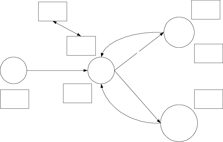
3.9 Factory/Depot/Installation Work Flow
IMUs, relays and gateways are expected to follow a certain work
flow during their lifetimes, as shown in Figure 2Figure 2Figure 2.
IMUs, relays and gateways are assembled at the factory. At this
point IMUs and relays are assigned a Utility Serial Number (i.e., pin #)
and a channel. Gateways should have their WANs activated, if possible.
IMUs, relays and gateways should be tested via the RF and (in the case of
gateways) via the WAN interface (see Gateway Node Noninvasive Test
Procedure Specification). The tool used to perform these functions is the
Factory Commissioning and Test tool.
IMUs, relays and gateways are manufactured in response to
projected demand, rather than for a specific utility order. Therefore, at
the factory utility serial numbers (i.e., pin numbers) are assigned
sequentially, but not associated with any specific Innovatec customer.
12
IMUs, relays and gateways are forwarded to a utility depot. At this
point they must be associated with a certain customer (for IMUs) or a
certain location and set of IMUs (for relays and gateways), the association
loaded into the network configuration database and work orders
generated and IMUs registered with their respective gateways. These
functions are preformed (directly or indirectly) using the Depot
Commissioning tool. In addition, the units may be tested again using the
Field Maintenance and Diagnosis tool.
Factory
Gateway &
Relay Pole
Locations
Utility
Customer
Site
Utility
Depot
IMU, Relay,
Gateway
IMU
IMU
(failed or
reused)
Relay,
Gateway
Relay,
Gateway
(failed or
reused)
Factory
Commisioning
& Test Tool
Depot
Commisioning
Tool
ENICS Server Field Service
Application
Field
Maintainence
& Diagnosis
Tool
Field
Maintainence
& Diagnosis
Tool
Field
Maintainence
& Diagnosis
Tool
Figure 2: IMU, Relay and Gateway work flow
Gateways and relays will move from the depot to their pole
locations. Gateways and relays are installed and tested using the Field
Maintenance and Diagnosis tool. Once gateways and relays have been
installed, the IMUs move from the depot to customer sites, where they
are installed, tested and their installation in the gateways verified using
the Field Service Application tool.
At some point in their lives IMUs, relays or gateways may be
replaced due to suspected failure or other reasons. These units go back
to the depot. Suspected failures may be explored using the Field
Maintenance and Diagnosis tool.
While both the depot commissioning tools and the network
configuration manager modify the network configuration database, the
depot commissioning tool is limited to filling in id (e.g., IMU utility serial
number) and address fields (e.g., WAN addresses) for units that have
already been entered into the network configuration database. This

13
implies that a unit must have already been added into the system by the
network configuration manager before the depot commissioning tool can
be used to modify its data, and that a null entry for certain fields must
be allowed in the network configuration database for IMUs, relays and
gateways that are marked as not installed.
4 Derived Requirements
Derived requirements are those that are driven by the primary
requirements, but are imposed on ourselves.
1.14.1 Supported applications
For those applications whose user interfaces are implemented
using Java applets, designers/implementers should strive to keep the
applets small, and implement any heavy duty operations in the servers
rather than in the applets themselves.
1.1.14.1.1 Supported interactive applications
Interactive applications are those whose functions are primarily
driven by an explicit user request, such as a meter read or a request to
upload a database from a field service application.
The Innovatec utility server system implements services for the
following user visible applications. These “applications” are not
necessarily implemented as monolithic applications in the traditional
sense, but they appear that way to end-users.
“Application” Purpose Required server functionality
Field Service
Application Install, decommission,
swap, calibrate, and
test meters in the field.
The primary users are
field service people.
Operates on a field
service laptop or
handheld computer
that may be out of
communication with
the rest of the system
for long periods of time.
• Specify set of service orders for
a particular service person (or
service id).
• Specify what is to be done for
each service order.
• Allow basic IMU
communications parameter
configuration (e.g., set the
channel number).
• Perform basic tests of meter
communication.
• Check that necessary network
setup has been completed to
allow service order function to
proceed for a given meter.
• Download service orders to
individual service laptops.
• Upload modified information
from individual service laptops

14
and integrate it into the
databases at the utility end.
• Calibrate water meters
Field
Monitoring and
Diagnosis Tool
Monitors RF traffic.
Performs diagnostic
tests of meters, relays
and gateways.
• Display all RF messages
received (should we allow for
filtering parameters?)
• Invoke diagnostic tests for
IMUs, relays and gateways via
the RF interface.
• Reprogram IMU
communications parameters
(e.g., meter utility id, channel
number, power).
• Query for all meters on a
channel.
• Scan channels for a meter
• Download gateway error and
event logs via RF.
• Perform pings via the WAN
from a gateway to the utility
(for WAN problem diagnosis),
invoked via the RF interface?
Factory
Commissioning
& Test tool
Checks IMUs and
relays to make sure
they’re properly
programmed with the
correct Utility Serial
Number, produces
factory log, performs
noninvasive gateway
testing.
• Checks IMUs and relays for
correctly programmed Utility
Serial Number and default
channel
• Performs noninvasive gateway
test.
• Generates factory log.
• If the meter supports an
internal record of factory
commissioning, update that
record once tests and
configuration have been
completed.
Depot
Commissioning
tool
Connects specific IMU,
relay and gateway ids to
customer accounts and
locations. Permits
gateways, relays and
IMUs to be replaced
with identical units.
Interactive
Meter Reader
Query meter readings
and status interactively.
The primary users are
• Isolate particular
customer/meter
• Read meter

15
utility customer service
people. • Query meter status
• Inform user when result of
operation is available.
Network
configuration
manager
Configure Innovatec
communications
network, perform
network diagnostics,
manage hardware and
software versions,
support field service
operations. The
primary users are
network maintainers at
the utility.
• View network logically.
• Supply data relating to
characteristics of a
communications path.
• Supply meter and gateway
statistics and logged history.
• Set up service orders
• Integrate modified service
order data into databases.
Alarm
configuration
manager
Configure which alarms
should be recognized
for specific IMUs.
• Activate/deactivate alarm
notification.
• Specify notification method
(e.g., on screen, hip pager).
Network
Emulator Emulates an Innovatec
communications
network. Allows the
introduction of alarms
or fault conditions (e.g.,
WAN link goes down)
interactively. Primary
users are utility
trainers and Innovatec
sales people.
• Replaces the gateway server’s
gateway agent.
• Reads network configuration
from a network configuration
database.
• Displays logical view of the
network.
• Allows a trainer or sales
person to interactively
introduce alarms and fault
conditions.
System
administration
tool
Allows a system
administrator to
view, configure
and control the
ENICS servers
and clients.
• View server configuration
information
• View active clients
• Startup/shutdown servers and
clients
• Add new hosts to ENICS
system, add or rearrange
utility servers in ENICS
system.
• View loading statistics.
• Add or delete users.
• Add or delete remote
redistribution servers.
Event log
viewer Allows data in the event
log tables to be viewed. • Filters events by type, date
and auxiliary characteristics

16
Allows archived event
log data to be viewed. specific to the event type.
Network
Planning and
Layout tool
Contains RF
propagation models
that allow an Innovatec
communications
network to be laid out
(e.g., site gateways and
relays given meter
locations, taking into
account RF propagation
characteristics).
Primary users are
network planners.
This tool will be bought
rather than built.
• Off the shelf tool will have its
own file formats and views.
Network
Planning
Database
converter
Converts from the file
formats used by the
network planning and
layout tool and imports
the data into the
internal Innovatec
Network and Planning
database.
•
1.1.24.1.2 Supported autonomous applications
An autonomous application is one that runs without significant
user intervention, such as the automatic health monitor.
Application Purpose Required server
functionality
Network exerciser Test the network
software and gateway
server, in house. The
primary users are
developers and testers
• Accepts set of
messages and
timing from a script
file.
• May be possible to
purchase this tool
rather than build it.
Network health
monitor Determines when an
element of the network
hasn’t been heard of in
some time. Pings
elements of the
network that may not
be responding.
• Ability to associate
IMUs with relays
and gateways.
• Ability to send ping
messages to the
communications
network.

17
• Ability to notify
users when
problems are
detected.
ENICS Health Monitor Periodically scans the
event log looking for
suspicious patterns of
activity, such as
multiple blocked login
attempts. Monitors
the internal health of
ENICS
processes/threads to
determine if a
malfunction has
occurred.
• Tells the alarm
receiver when a
suspicious pattern
of activity is
detected or a
malfunction occurs.
Message Monitor Moves journaled
sent/received
messages from the
gateway server into the
logging database for
subsequent use by
other applications.
• Ability to access
record of all
messages sent and
received.
Logged Event Pruner Deletes data from the
logging database that
is older than some
configurable maximum
age. The data may
optionally be logged to
an external medium
such as CD-ROM or
tape, rather than
deleted.
• Ability to do queries
and deletes on the
logging database.
Gateway Logged Event
Gatherer
Periodically gathers up
the error and event
logs maintained in the
gateway nodes.
•
Alarm receiver Acts when an alarm is
received.
Notified when an
internal ENICS
component wants to
raise an alarm.
• Ability to cause
alarm display
applet to be
updated.
• Ability to cause 3rd
party devices (such
as hip pagers) to be
activated.

18
1.24.2 Supported Databases
While the general set of data present in the internal databases is
derived from the primary requirements, its partition into specific
databases is a high level architecture decision.
1.1.14.2.1 Internal databases
The utility server software shall support access to and
maintenance of the following internal databases, independently for each
utility supported. The databases referred to in this section are abstract
entities introduced for the purposes of requirements analysis and will not
necessarily be implemented as databases in the sense of an JDBC (or
other protocol) database entity. The assignment of data to specific tables
and the assignment of tables to specific databases will be done in part in
the system architecture design and in part in the utility server design.
Database Record Type Item Comment
Network Configuration,
Network Planning Gateway • Gateway id
• Gateway WAN Type
• Hardware revision
number
• Software revision
number
• Operating system
revision number
• Gateway application
(gw.zip) revision
number
• Classes.zip revision
number
• Patch file contents
and revision numbers
• Location information
Patch file
may be a
separate
record type
or even in a
separate
table.
Location
information
may include
lat, long,
elevation
and pole # .
Relay • Relay id
• Relay hardware
revision number
• Relay software
revision number
• Location information
Location
information
may include
lat, long,
elevation
and pole # .
Meter • Utility Id (AKA utility
serial number, pin
number)
• Meter type
• Location information
• Calibration Factor (for
water meters)
Location
information
may include
lat, long,
elevation
and pole # .
Supported
WANs • WAN type designation
• WAN PIN number
Gateway-IMU • Gateway id

19
association
information • IMU id that is
registered with
gateway
• Option relay id that
IMU is registered with
Software/Hardware
version compatibility Use to keep
track of which
gateways,
relays and
meter versions
are compatible
with other
versions.
• This is
intended to
act as an
error
checking
mechanism.
This
database is
static from
the utilities
point of
view, and
would be
supplied by
Innovatec
each time a
new
gateway,
relay or IMU
version came
out.
Alarm configuration Alarm activity
information • IMU id
• Alarm type
• Alarm active or
inactive
• Time of last activation
(or should this be an
alarm history?)
Alarm
notification
information
• IMU id
• Alarm type
• Notification type
specification
Notification
type record.
Typically
there’ll be one
of these for
every
notification
destination/des
tination type.
E.g., one for
each pager that
could be
notified that an
alarm has
arrived.
• Notification type
• Device specific data
(e.g., PIN number for
a pager, display
device for on screen
notification)
Logging Keeps track of
interesting • Time event was logged
• Event type
The design
of this

20
events that
happen in the
system. This
includes but is
not restricted to
message
transmissions
and receptions.
• Auxiliary information database is
not likely to
be one
monolithic
table, as the
“auxiliary
information”
may be used
to do
lookups in
other tables.
Authorized users Keeps track of
authorized user
names,
passwords and
authorized
hosts.
•
Authorized external data
distribution targets. Keeps track of
other ENICS
servers to
which data may
be distributed.
•
Extern data distribution
meter configuration table Keeps track of
what alarms
and status are
available to an
external utility
and what
alarms may be
configured.
•
External data distribution
target transaction log Keeps track of
the
transactions
performed by
an external
utility (e.g.,
number meter
reads) for
billing
purposes.
• Meter utility id
• Transaction type
• Number transactions
•
Field Service Application
Database Keeps track of
work orders
that have been
generated or
uploaded
• Service order number
• Installer
• Open/close dates
• IMU information
• Customer information
• IMU location
information
• Time stamps for as
found/as left changes
Application Configuration
Database Keeps track of
user settable
options for the
various
applications
• Application Name
• User name
It may make
sense to
keep this
data in the
NT registry

21
(possibly on a
per user basis,
where that
makes sense).
on the
server.
However the
interface the
applets and
applications
see should
be through a
servant.
4.3 Permissions
Access control permissions (or just permissions) in the ENICS
system apply to all applications (including both Java applications and
applets) that may be initiated outside of the server environment.
Applications that are initiated by and run under the control of the ENICS
server environment (such as the network health monitor) do not require
access permissions. Access permissions are assigned out of the available
options on a user by user basis.
Each application has three sets of permissions. The first “set”
determines whether a user is allowed to access the ENICS server while
running a particular application. For example, a user may be granted
permission to run the Interactive Meter Reader, but not the Network
Configuration Manager. This is not a security measure, since the only
way the ENICS server has to know what application is being run is for
the application to tell it. Thus, this sort of permission won’t be able to
deter a cracker who writes his or her own application, but it will give the
system administrator control over who can run applications under
normal circumstances.
The second set controls access to the various database tables in
the system. An application may have read, modify and append
permission for a table. Append is a restricted type of write access that
allows an application to add new records to a table, but not to either
modify or read records that already exist. Modify access implies both
read and append access. For databases that contain information that is
associated with particular users, users may be granted permission to
read or modify data for themselves only or for all users.
The third set of permissions controls access to the
communications network. The first access permission is “network use”.
This allows an application to interact with the communications network.
If it is not set, then the application is not allowed to interact with the
communications server. The second network access permission is IMU
read/modify, which determine which types of messages that can get or
set IMU information are allowed to be sent. The third network access
permission is network read/modify, which determines which messages
can be sent that may read information from or modify gateways and
relays. Please note that even an application that has no explicit network

22
access may invoke an operation that will cause the ENICS server to
access the network.
1.34.4 COM Access
In order to support miscellaneous analysis and data gathering
capabilities, a COM interface to the ENICS business objects shall be
implemented. This will allow programs to be written in Visual Basic that
can retrieve information from the ENICS system. The COM interface
shall be design in such a way that it shall not be possible to compromise
ENICS server or Innovatec network communications using the interface.
A set of standard Visual Basic applications should be implemented
for common operations such as gathering reads from a predefined group
of meters and gathering time of use information. These standard
applications will serve to get Innovatec customer’s started using the more
exotic functions of the system quickly and also server as examples for
Innovatec customer IT departments that wish to implement their own
data analysis programs.
1.44.5 Required Requirements
All application requirements documents shall include the following:
1. Startup
2. Shutdown
3. I/O interfaces, if any.
4. Required services.
5. Behavior in the event of errors, including but not limited to
internal program errors, communications errors, database
access errors and server access errors.
6. Mechanism for notifying users when a problem is detected (e.g.,
dialog box, logged event).
7. Which events should be logged (e.g., significant user actions).
4.54.6 Innovatec Look and Feel
4.5.14.6.1 Pluggable Look and Feel
All enics applications should implement the
com.innovatec.plaf.InnovatecLookAndFeel look and feel.
import com.innovatec.plaf.InnovatecLookAndFeel;
...
static{
try{
UIManager.setLookAndFeel( new InnovatecLookAndFeel() );
}
catch( Exception e ){}
}

23
1.1.24.6.2 Colors
4.5.2.14.6.2.1 Foreground/Text
Foreground colors should contrast extremely with the background.
Since most of our background colors are very light, labels, and text areas
will have black foreground colors. Buttons on the other hand have very
dark backgrounds, so their text will normally be white.
1.1.1.24.6.2.2 Background
Backgrounds for panels should be light and change in color and or
image with different concept area. For example if there are two panels on
one screen that represent different ideas, utility record and meter status,
they should be of different colors to make them easily distinguishable.
Since colors cannot be completely relied upon due to color
blindness, images with different subtle textures should be used as well.
Images can be added by using com.innovatec.ui.BasicPanel instead of
JPanel, and setting the image through
BasicPanel.setBackgroundImage.
1.64.7 Navigation
4.6.14.7.1 Keyboard
In general, navigating between components follows these rules.
• Tab or Ctrl-Tab. Moves keyboard focus to the next component or to
the first member of the next group of components. Use Ctrl-Tab when
the component itself accepts tabs, as in text fields, tables, and tabbed
panes.
• Shift-Tab. Moves keyboard focus to the previous component or to the
first component in the previous group of components.
• Arrow keys. Moves keyboard focus within the individual components
of a group of components, for example, within menu items in a menu
or within radio buttons in a group of radio buttons.
Most of the keyboard navigation is taken care of by Java, some
changes in tab order may need to be implemented by specifying the
next focusable component to a component. This can be accomplished
by JComponent.setNextFocusableComponent.
1.1.1.14.7.1.1 Mnemonics
Mnemonics are another keyboard alternative to the mouse.
Mnemonics can be used to navigate menus.
Rules of thumb for creating mnemonics:
1. If the mnemonic does not appear in the table of common
mnemonics, choose the first letter of the menu item. For instance,
choose J for Justify.

24
2. If the first letter of the menu item conflicts with those of other
menus, choose a prominent consonant. For instance, the letter S
has already been designated as the mnemonic for the Style
command. Therefore, choose the letter Z as the mnemonic for the
Size command.
3. If the first letter of the menu item and the prominent consonant
conflict with those of other menu items, choose a prominent vowel.
Mnemonics can be set by AbstractButton.setMnemonic.
Mnemonics can also be added to any item with a label. This can
make it very easy to go directly to a component and add information.
A mnemonic can be added to a component via the label by
JLabel.setLabelFor and JLabel.setDisplayMnemonic.
1.1.1.24.7.1.2 Shortcuts
All common commands should have a short cut key strokes, these
should be clearly labeled on the menu and or button for that command.
The same shortcut key cannot refer to different actions in the
application. Here is partial list of shortcut keys and their purpose:
Common Shortcut combinations include:
Ctrl-N New (File Menu)
Ctrl-O Open (File Menu)
Ctrl-S Save (File Menu)
Ctrl-P Print (File Menu)
Ctrl-Z Undo (Edit Menu)
Ctrl-X Cut (Edit Menu)
Ctrl-C Copy (Edit Menu)
Ctrl-V Paste (Edit Menu)
Ctrl-F Find (Edit Menu)
Ctrl-A Select All (Edit Menu)
F1 Help
Ctrl-Q Exit Application
1.1.24.7.2 Mouse
A user can navigate through applications with the mouse.
Specifically clicking once on an enabled button should cause that
buttons action to occur. Clicking once on an editable text component
should cause the text caret to be placed and put the text component in
insert mode.
1.74.8 Components
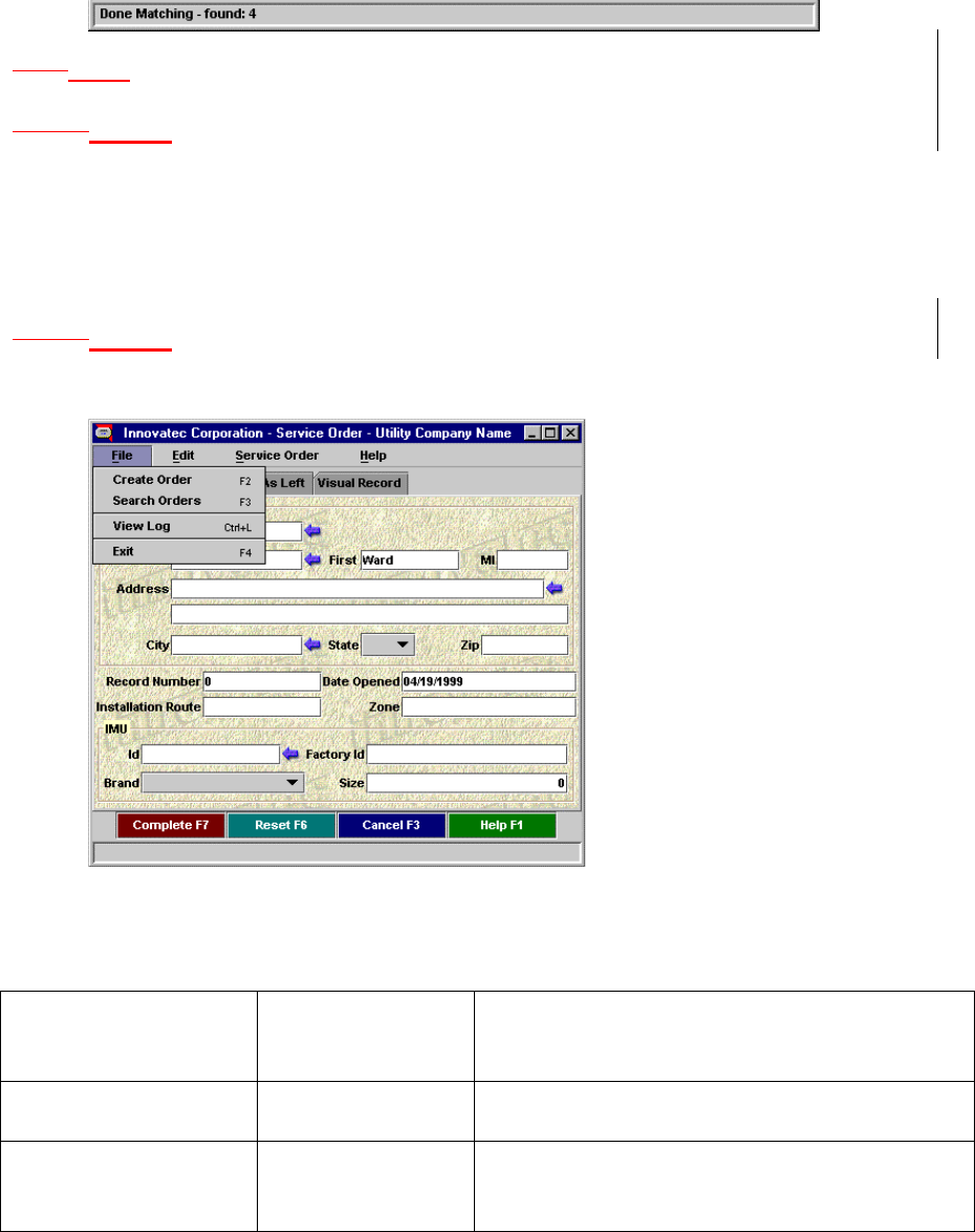
4.7.14.8.1 Primary Windows
A primary window is a window used as primary communication
with the user by the application. This is where the user will return to in
order initiate different functionality. A Primary Window shall consist of a
25
Titlebar giving the name of the application, frame, and what is being
done.
1.1.24.8.2 Secondary Windows
4.7.2.14.8.2.1 Dialogs
Dialogs are small windows used to concisely communicate with the
user.
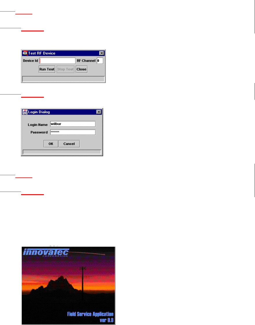
1.1.1.24.8.2.2 Login Dialog
Prompt the user for login name and password.
Use com.innovatec.ui.LoginDialog.
1.1.34.8.3 Plain Windows
4.7.3.14.8.3.1 Splash Screens
A splash screen is a window with no standard window decorations
(titlebar, close, minimize, maximize icons) that informs the user that the
software is loading and what exactly the program is.
A splash screen in ENICS shall consist of the Innovatec logo, an
image for the application, the application logo, version, and copyright
information.

26
1.1.44.8.4 A splash screen should be implemented using
com.innovatec.ui.Jsplash. The application name, version and copyright
information should appear on all splash screens.Applets
Applets can be broken down into two types, simple and complex.
How an applet is displayed depends on what type of applet it is. A simple
applet would consist of one screen, no menus, no toolbars, no status bar.
This type of applet should be displayed within the browser window and
should not add the confusion of creating another frame.
A complex applet is one that needs to be interacted with from
another frame. A separate frame allows clear delineation between the
applet’s menus, toolbars, statusbar, and the browser’s equivalent. A
code snippet for a complex applet’s frame could look like this:
public void init(){
...
frame = new JFrame();
frame.getContentPane().add( panel );
...
}
public void start(){
...
frame.setVisible( true );
...
}
public void stop(){
...
frame.setVisible( false );
...
}
This will make the applet a non-visual component, and the visual
components are added the frame itself.
1.1.54.8.5 Buttons
Buttons should be different colors from each other and the
background, colors can be repeated, but as far from a button of the same
color as possible.
1.1.1.14.8.5.1 Toolbars
Icons on toolbars will match icons for buttons and or menus.
1.1.64.8.6 Menus
All commands available should also be made available by menu.
As much as possible all menus should have shortcut keys and or
mnemonic associated with them. If a menu shares functionality with a
button is should share the same label.
1.1.74.8.7 Statusbar
Small bar at the bottom used to convey information to the user.
The status bar should be used before a dialog box if at all possible. Error
27
messages should be in Red. Successful completion should be indicated
with black.
For implementation use com.innovatec.ui.StatusBar.
1.1.84.8.8 Organizing
4.7.8.14.8.8.1 Group Boxes
Used to group like concepts. Group boxes should used sparingly
and group boxes within group boxes should be avoided, they can become
confusing very fast and add very little to the organization of the screen.
Instead of Group boxes consider having titles for areas, labels that
extend slightly more left than the rest.
1.1.1.24.8.8.2 Tabbed Panes
Tabbed panes are the preferred method of breaking large hunks of
data that are only tied together by a process.
5 Change Log
Date Applications/
Subsystems
Affected
Description of changes
5/17/99, Revision
0.2 Changed revision number to 0.2 from
0.1.92
5/17/99, Revision
0.2 Remove action item for authentication
of remote redistribution servers. It
was decided in requirements review

28
that host identification and the risks it
presents were tolerable and the way to
go.
5/17/99, Revision
0.2 Added meter model to physical assets
database.
5/17/99, Revision
0.2 Moved PIN number and calibration
factor data out of the specs for the
physical assets database and into the
network configuration database.
5/18/99, Revision
0.2 Added logging for remote distribution
server applications.
5/18/99, Revision
0.2 Added alarm by alarm and meter by
meter configuration for remote data
distribution.
5/18/99, Revision
0.2 Added use of factory commissioning
signature in IMU for factory
commissioning tool if the meter
supports it.
5/18/99, Revision
0.2 Remove requirements for physical
display of Innovatec communications
network.
5/18/99, Revision
0.2 Updated shortcut keys: Changed Exit
Application from F4 to Ctrl-Q.
Assigned find to Ctrl-F and Paste to
Ctrl-V which is Windows standard.
5/18/99, Revision
0.2
Changed typo in Statusbar area that
said successful messages should be in
red, should be in black.
6/4/99, Revision
0.2 Add requirements for ENICS Health
monitor, add requirement for alarm
monitor to allow for server generated
alarms (in addition to alarm
messages).
6/4/99, Revision
0.2 Added requirements for COM
interface.
6/4/99, Revision
0.2 Add field service application database
to internal database requirements.
6/15/99 Revision
0.2 Signoff complete