Itron 963 Gas Pulse Interface User Manual Commercial Industrial Gas Meter IMU Interface
Silver Spring Networks Gas Pulse Interface Commercial Industrial Gas Meter IMU Interface
Itron >
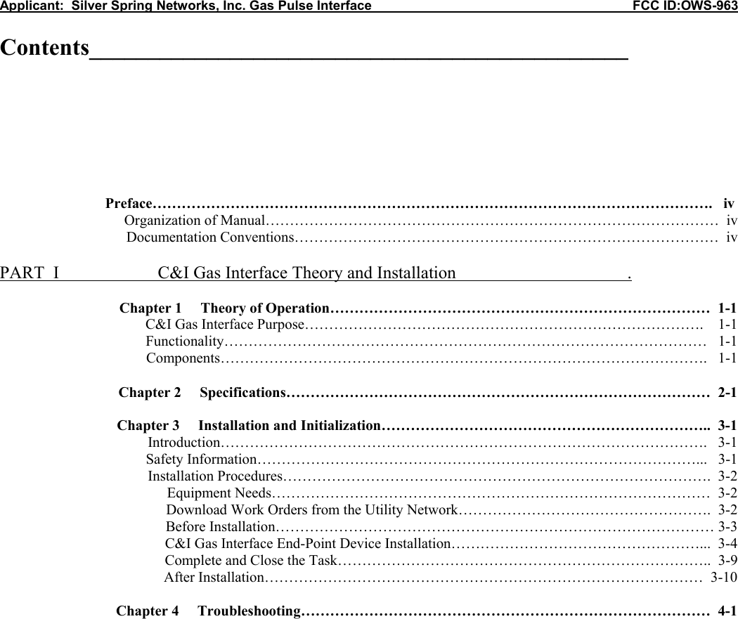
Contents
- 1. Operations User Manual
- 2. User Manual
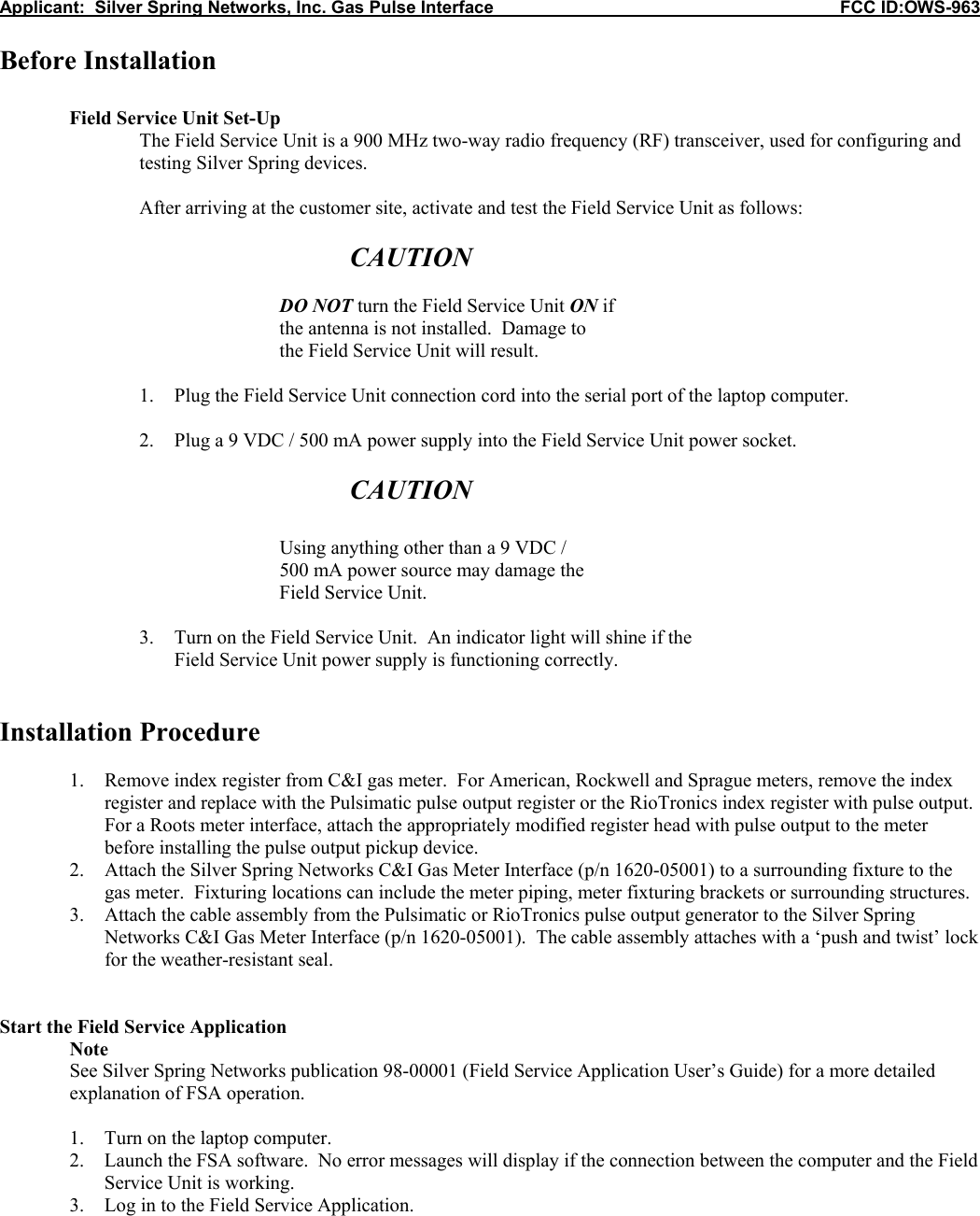
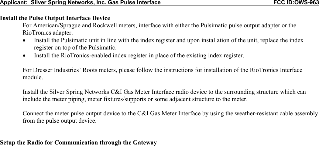
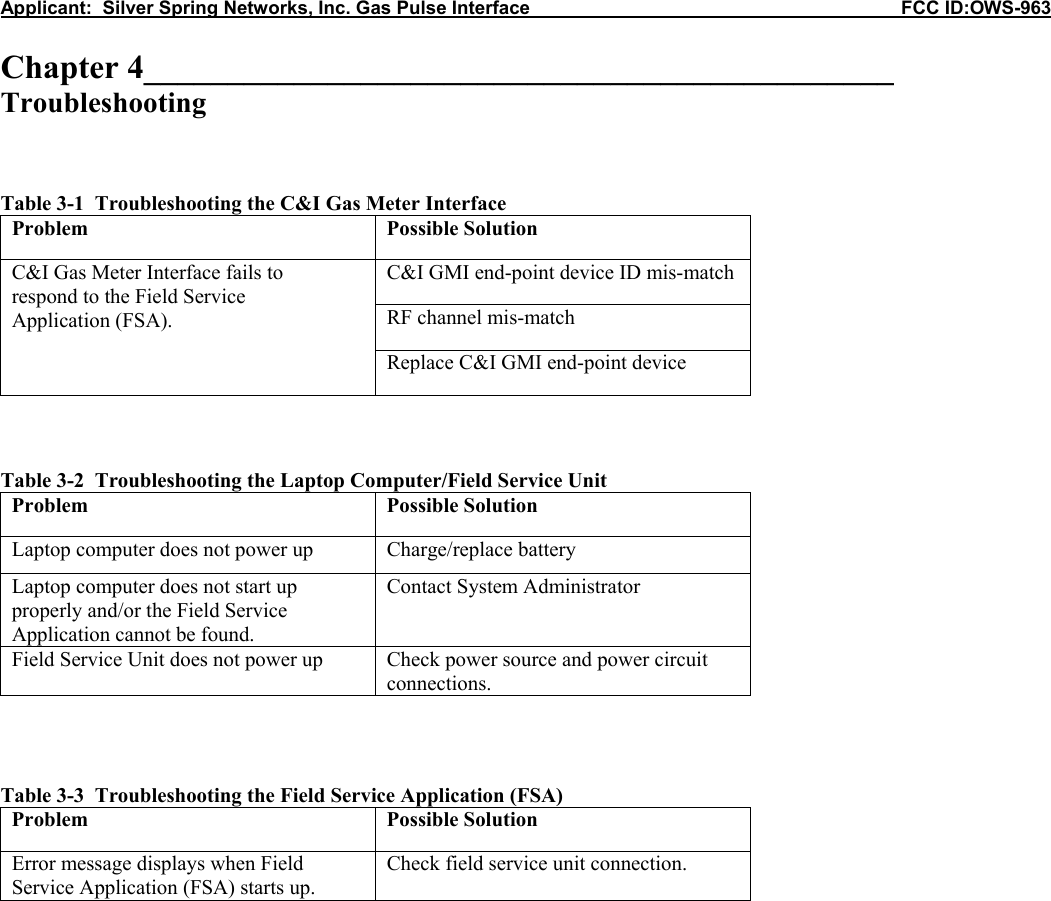
Operations User Manual