Itron AMI-1 CENTRON OPEN WAY ELECTRICITY METER User Manual USERS MANUAL
Itron Electricity Metering, Inc. CENTRON OPEN WAY ELECTRICITY METER USERS MANUAL
Itron >
USERS MANUAL

5015 B.U. Bowman Drive Buford, GA 30518 USA Voice: 770-831-8048 Fax: 770-831-8598
FCC Part 15.247/15.249
Transmitter Certification
Composite Device
Test Report
FCC ID: SK9AMI-1
FCC Rule Part: 15.247/15.249
ACS Report Number: 06-0239-15C-DSS, 06-0239-15C-DXX
Manufacturer: Itron Electricity Metering Inc.
Trade Name: CENTRON Open Way
Model(s): CVSO, CVSOD, CVSOC
Manual

CENTRON® OpenWay™ Meter
Technical Reference Guide
Effective Date: September 26, 2006
Draft

ii CENTRON® OpenWay™ Meter Technical Reference Guide
This manual contains the trade secrets and confidential information of Itron, Inc., which are not to be divulged to
third parties and may not be reproduced or transmitted in whole or part, in any form or by any means, electronic or
mechanical for any purpose, without the express written permission of Itron, Inc. All rights to designs or inventions
disclosed herein, including the right to manufacture, are reserved to Itron, Inc.
The information contained in this document is subject to change without notice. Itron, Inc. reserves the right to
change the product specifications at any time without incurring any obligations.
Trademarks Used in This Manual
CENTRON is a registered trademark of Itron, Inc.
Windows is a trademark of Microsoft Corporation
CENTRON® OpenWay™ Meter Technical Reference Guide
100699GM-01
Itron, Inc.
Corporate Headquarters
2818 North Sullivan Road
Spokane Valley, WA 99216
U.S.A.
Tel: (509) 924-9900
Fax: (509) 891-3355
Itron, Inc.
Oconee Electricity Metering
313-B North Highway 11
West Union, SC 29696
U.S.A.
Tel: (864) 638-8300
Fax: (864) 638-4950
www.itron.com Copyright© 2006
Itron, Inc.
All rights reserved.
Draft

CENTRON® OpenWay™ Meter Technical Reference Guide iii
Compliance With FCC Regulations
FCC Part 15, Class B
This equipment has been tested and found to comply with the limits for a Class B digital device, pursuant to Part 15
of the FCC Rules. These limits are designed to provide reasonable protection against harmful interference in a
residential installation. This equipment generates uses and can radiate radio frequency energy and, if not installed
and used in accordance with the instructions, may cause harmful interference to radio communications. However,
there is no guarantee that interference will not occur in a particular installation. If this equipment does cause harmful
interference to radio or television reception, which can be determined by turning the equipment off and on, the user
is encouraged to try to correct the interference by one or more of the following measures:
Reorient or relocate the receiving antenna.
Increase the separation between the equipment and receiver.
Connect the equipment into an outlet on a circuit different from that to which the receiver is connected.
Consult the dealer or an experienced radio/TV technician for help.
Changes or modifications to this device not expressly approved by Itron,
Inc. could void the user’s authority to operate the equipment.
Co-existance of Transmitter
This device is authorized to operate simultaniously with GPRS transmitter FCC ID MIVGSM0108
RF Exposure
In accordance with FCC requirements of human exposure to radiofrequency fields, the radiating element shall be
installed such that a minimum separation distance of 20 cm.
Canadian Interference Causing Equipment Regulations
This Class B digital apparatus meets all requirements of the Canadian Interference Causing Equipment Regulations.
Operation is subject to the following two conditions: (1) this device may not cause harmful interference, and (2) this
device must accept any interference received, including interference that may cause undesired operation.
Cet appareillage numérique de la classe B répond à toutes les exigences de l'interférence Canadienne causant des
règlements d'équipement. L'opération est sujette aux deux conditions suivantes: (1) ce dispositif peut ne pas causer
l'interférence nocive, et (2) ce dispositif doit accepter n'importe quelle interférence reçue, y compris l'interférence qui
peut causer l'opération peu désirée.
Factory Repair of Meters
Itron recommends that all repairs be performed at the factory. Certain repairs may be performed by the user;
however, unauthorized repairs will void any existing warranty. All surface mounted parts must be replaced by the
factory.
Draft

iv CENTRON® OpenWay™ Meter Technical Reference Guide
Repair of Meters Under Warranty
If the meter is under warranty, then Itron, Inc. will repair the meter at no charge if the meter has failed due to
components or workmanship. A return authorization number must be obtained before the equipment can be sent back
to the factory. Contact your Itron Sales Representative for assistance.
Repair of Meters Not Under Warranty
The same procedure as above applies. Itron will charge for the necessary repairs based on the failure.
Service Return Address
Itron, Inc.
Customer Repair Department
313 North Highway 11 Dock C
West Union, SC 29696
Recycling Information
The product you have purchased contains a battery (or batteries), circuit boards, and switches. The batteries are
recyclable. At the end of the meter’s useful life, under various state and local laws, it may be illegal to dispose of
certain components into the municipal waste system. Check with your local solid waste officials for details about
recycling options or proper disposal.
Although polycarbonate is not a commonly recycled plastic, the recycling number for the polycarbonate inner cover,
outer cover, and base is seven (7).
Draft

CENTRON® OpenWay™ Meter Technical Reference Guide v
Table of Contents
Trademarks Used in This Manual..................................................................................................ii
Compliance With FCC Regulations .............................................................................................. iii
FCC Part 15, Class B ......................................................................................................... iii
RF Exposure....................................................................................................................... iii
Canadian Interference Causing Equipment Regulations ................................................... iii
Factory Repair of Meters .............................................................................................................. iii
Repair of Meters Under Warranty....................................................................................... iv
Repair of Meters Not Under Warranty................................................................................ iv
Service Return Address...................................................................................................... iv
Recycling Information.................................................................................................................... iv
General Information ..................................................................................................1
About This Manual .........................................................................................................................1
General Description .......................................................................................................................2
Physical Description.......................................................................................................................3
Meter Base ..........................................................................................................................3
Personality Modules ............................................................................................................3
Product Availability.........................................................................................................................4
Display Functions...........................................................................................................................4
Specifications.................................................................................................................................5
Electrical ..............................................................................................................................5
Operating Environment........................................................................................................5
Characteristic Data ..............................................................................................................5
Burden Data.........................................................................................................................6
Technical Data.....................................................................................................................6
Type Codes .........................................................................................................................7
Dimensions..........................................................................................................................8
CVSO ........................................................................................................................8
CVSOD, CVSOR, CVSOC.......................................................................................................9
Installation ...............................................................................................................11
Inspection.....................................................................................................................................11
Battery..........................................................................................................................................11
Storage.........................................................................................................................................11
Unpacking ....................................................................................................................................12
Preliminary Inspection..................................................................................................................12
Meters Without Batteries ...................................................................................................12
Meters With Batteries ........................................................................................................12
Selecting a Site ............................................................................................................................13
Installing the Meter into Service...................................................................................................13
Retrofitting with Personality Modules...........................................................................................13
Operation: Base Metrology.....................................................................................15
Metrology .....................................................................................................................................15
Surge Protection ..........................................................................................................................16
Sampling ......................................................................................................................................16
Voltage and Current Measurement..............................................................................................17
Watthour (Wh) Measurement.......................................................................................................17
Volt-amperehour (VAh) Measurement.........................................................................................18
Draft

Table of Contents
vi CENTRON® OpenWay™ Meter Technical Reference Guide
Demand Calculations...................................................................................................................18
Block Interval Demand Calculation....................................................................................19
Rolling/Sliding Demand Interval Calculation .....................................................................19
Cumulative Demand Values..............................................................................................19
Continuous Cumulative Demand Values...........................................................................20
Present Demand................................................................................................................20
Previous Demand ..............................................................................................................20
Peak Demand (Maximum Demand) ..................................................................................20
Demand Thresholds ..........................................................................................................20
Coincident Demand ...........................................................................................................21
Operation: CVSO OpenWay Register ....................................................................23
Controls and Indicators ................................................................................................................24
Infrared Test LED ..............................................................................................................24
Liquid Crystal Display (LCD) .............................................................................................25
Load Emulator .........................................................................................................26
Power Circle Quadrants ..........................................................................................27
Optical Port ........................................................................................................................27
Factory Reset...............................................................................................................................28
Application of Power and Power-up.............................................................................................28
Power Down Procedures .............................................................................................................28
Demand Meter ...................................................................................................................28
TOU/Load Profile Meters...................................................................................................28
Cold Load Pickup...............................................................................................................29
Interval Make-up................................................................................................................29
Operating Modes..........................................................................................................................29
Normal Mode .....................................................................................................................29
Test Mode..........................................................................................................................30
Test Mode Timeout .................................................................................................30
Display Modes..............................................................................................................................30
Energy Data Display Items ................................................................................................31
Demand Data Display Items..............................................................................................31
Instantaneous Data Display Items.....................................................................................32
Informational Data Display Items.......................................................................................32
Magnetic Switch.................................................................................................................34
Scroll Lock .........................................................................................................................34
Changing Display Modes...................................................................................................34
Mode Timeout....................................................................................................................34
Normal Display Mode ........................................................................................................34
Alternate Display Mode .....................................................................................................34
Toolbox Display Mode .......................................................................................................35
Test Display Mode.............................................................................................................36
Test Alternate Display Mode .............................................................................................37
Diagnostic Displays ...........................................................................................................37
Registers ......................................................................................................................................37
Energy Registers ...............................................................................................................37
Demand Registers.............................................................................................................38
Instantaneous Registers....................................................................................................39
Self Read and Snapshot Registers ...................................................................................39
Information Registers ........................................................................................................39
Interrogation and Programming ...................................................................................................39
Interrogation.......................................................................................................................39
Programming .....................................................................................................................40
Time-of-Use (TOU) ......................................................................................................................40
Draft

Table of Contents
CENTRON® OpenWay™ Meter Technical Reference Guide vii
TOU Schedules .................................................................................................................40
Calendar Schedule..................................................................................................40
Rates .......................................................................................................................40
Daily Patterns ..........................................................................................................41
Day Types ...............................................................................................................41
Seasonal Schedules................................................................................................41
TOU Registers...................................................................................................................41
Current Season Registers .......................................................................................41
Last Season Registers ............................................................................................41
TOU Operation ..................................................................................................................41
Rate Annunciators and Active Rate Indicators........................................................42
Season Change.......................................................................................................42
Battery Carryover ....................................................................................................42
Load Profile..................................................................................................................................43
Load Profile Specifications ................................................................................................43
Capacity...................................................................................................................43
Bit Resolution ..........................................................................................................43
Interval Lengths.......................................................................................................43
Power Outage..........................................................................................................44
Channel Configuration.......................................................................................................44
Pulse Constants.................................................................................................................44
Data Storage......................................................................................................................45
Recording Duration............................................................................................................45
Event Log .....................................................................................................................................46
Security Codes.............................................................................................................................48
Implementing Security Codes............................................................................................49
Clearing Security Codes....................................................................................................49
Firmware Upgrades......................................................................................................................50
Installing D/T/L Register Firmware on the PC...................................................................50
R300CD/CD3 ...............................................................................................................................50
Testing, Troubleshooting, and Maintenance................................................................................52
Visual Indicators ................................................................................................................53
Infrared Test LED ....................................................................................................53
Annunciators......................................................................................................................53
Load Indication/Direction Annunciator ....................................................................53
Phase-Voltage Indication Annunciators ..................................................................54
Nominal Voltage Indication Annunciator .................................................................54
Test Mode Annunciator ...........................................................................................54
Energy Testing...................................................................................................................55
Testing With the Infrared Test LED.........................................................................55
Testing Using the Load Indication Annunciator.......................................................55
Testing Using the Energy/Time Method..................................................................56
Recommended Energy Testing Procedures .....................................................................56
Test Description.......................................................................................................56
Recommendations ..................................................................................................57
Demand Testing ................................................................................................................58
Demand Test Method..............................................................................................59
Demand Calculations ..............................................................................................60
Field Testing ......................................................................................................................61
Required Hardware .................................................................................................61
Test Method Using Infrared Pulse Adapter .............................................................61
Test Method Using a Snap Switch Assembly .........................................................61
Troubleshooting.................................................................................................................62
Fatal Errors..............................................................................................................62
Non-Fatal Errors......................................................................................................63
Draft

Table of Contents
viii CENTRON® OpenWay™ Meter Technical Reference Guide
Other Problems .......................................................................................................66
Maintenance ......................................................................................................................68
Preventive Maintenance..........................................................................................68
Corrective Maintenance ..........................................................................................68
Operation: CP1SR Version .....................................................................................69
Physical Description.....................................................................................................................70
FCC Regulations..........................................................................................................................70
Tamper Detection.........................................................................................................................70
Testing the CENTRON Polyphase CP1SR Tamper Counter............................................70
SCM Testing............................................................................................................70
Retrofitting the CP1SR Personality Module.................................................................................72
Testing, Troubleshooting and Maintenance.................................................................................72
Testing Support Features ..................................................................................................73
Infrared Test LED ....................................................................................................73
Pulse Detector.........................................................................................................73
Annunciators......................................................................................................................74
Watthour Annunciators............................................................................................74
Glossary of Terms...................................................................................................75
Index.........................................................................................................................77
Draft

CENTRON® OpenWay™ Meter Technical Reference Guide ix
Table of Figures
Figure 1: CENTRON OpenWay Meter Personality Modules .........................................................2
Figure 2: CENTRON OpenWay Meter Metrology..........................................................................3
Figure 3: CENTRON OpenWay Module Assembly .......................................................................4
Figure 4: CENTRON OpenWay Meter Type Codes ......................................................................7
Figure 5: CVSO Dimensions..........................................................................................................8
Figure 6: CVSOD, CVSOC Dimensions ........................................................................................9
Figure 7: CENTRON OpenWay Metrology..................................................................................15
Figure 8: Sampled Waveform ......................................................................................................16
Figure 9: Voltage and Current Measurement ..............................................................................17
Figure 10: CENTRON CVSO Meter ............................................................................................23
Figure 11: Controls and Indicators...............................................................................................24
Figure 12: CENTRON OpenWay LCD.........................................................................................25
Figure 13: Load Emulator Segment Progression for Delivered Power........................................26
Figure 14: Load Emulator Segment Progression for Received Power........................................26
Figure 15: Power Circle Diagram.................................................................................................27
Figure 16: Load Emulator Segment Progression.........................................................................54
Figure 17: Test Connections........................................................................................................59
Figure 18: CENTRON CP1SR Meter...........................................................................................69
Figure 19: CENTRON Polyphase CP1SR Meter.........................................................................72
Figure 20: Test LED Location ......................................................................................................73
Figure 21: Pulse Detector ............................................................................................................74
Draft

Table of Figures
x
CENTRON® OpenWay™ Meter Technical Reference Guide
Notes:
Draft

CENTRON® OpenWay™ Meter Technical Reference Guide 1
In This Chapter
About This Manual................................................................................................1
General Description...............................................................................................2
Physical Description ..............................................................................................3
Product Availability...............................................................................................4
Display Functions..................................................................................................4
Specifications.........................................................................................................5
This technical reference guide describes the installation, operation, and maintenance of the
Itron CENTRON OpenWay meter. Itron urges you to read the entire manual before
attempting installation, testing, operation, or maintenance of a meter. To operate the Itron
PC-PRO+ Advanced Programming Software discussed in this manual, refer to the online
user manuals that are installed with the PC-PRO+ Advanced software.
The online software manuals are in Adobe® Portable Document Format (PDF) and are
accessible from the Windows Start menu. The Adobe Reader is required to view and
print these manuals. The Adobe Reader is free and can be downloaded from
http://www.adobe.com.
About This Manual
This manual contains the following information as listed in the chapter descriptions below:
Chapter Title Description
General Information Provides a general description, operation, physical
and functional descriptions, and complete CENTRON
OpenWay meter specifications.
Installation Gives instructions for the proper handling and
installation.
Operation: Base Metrology Describes the measurement technique used for the
base on the CENTRON OpenWay meter.
Operation: CVSO Provides detailed information and theoretical operation
for the OpenWay module with TOU, Demand, and
Load Profile capabilities.
Operation: Zigbee Radio Provides a physical description and the operational
characteristics of the Zigbee 2.4 GHz radio.
Testing, Troubleshooting,
and Maintenance Provides an explanation of the testing,
troubleshooting, and maintenance of the CENTRON
OpenWay meter.
CHAPTER 1
General Information
Draft

General Information
2 CENTRON® OpenWay™ Meter Technical Reference Guide
Chapter Title Description
Specification Numbers and
Drawings Provides a reference to meter part numbers and
shows meter form drawings.
General Description
The CENTRON OpenWay meter is used for measuring electrical energy consumption. The
CENTRON OpenWay meter incorporates a two-piece design combining a base metrology
with a variety of OpenWay registers or options. The metrology portion of the meter contains
all measurement circuitry and calibration information, while the personality modules
contain the register functionality and communication mediums.
Each version of the meter is distinguished by the various personality modules or option
boards that mount to the standard meter metrology base. The CENTRON OpenWay meter
is also available with a remote disconnect which is located in the bottom of the meter
housing. The CENTRON OpenWay meter is available in the following versions:
Standard-CVSO
Integrated disconnect/reconnect - CVSOD
Integrated cell relay - CVSOR, CVSOC
Figure 1: CENTRON OpenWay Meter Personality Modules
Draft

General Information
CENTRON® OpenWay™ Meter Technical Reference Guide 3
Physical Description
The CENTRON OpenWay meter features a common meter base to which various
personality modules are attached. The cover is polycarbonate. Meters with the disconnect
or integrated cell relay have an extended cover.
Meter Base
The CENTRON OpenWay meter base contains all of the measurement circuitry and
calibration information on the metrology board.
Figure 2: CENTRON OpenWay Meter Metrology
Personality Modules
All of the personality modules in the CENTRON OpenWay meter snap into the module
holder located on the standard meter base as shown below. From the base metrology, the
energy data is transmitted to the OpenWay module, which contains the meter display,
communication mediums, and register functionality.
Draft

General Information
4 CENTRON® OpenWay™ Meter Technical Reference Guide
Figure 3: CENTRON OpenWay Module Assembly
Product Availability
The current offerings for the CENTRON are:
Metrology Class 200, 240V , Form 2S
Personality Modules Standard OpenWay Register
OEM Communications Modules
Additional Base Functionality CellRelay
Remote Disconnect/Reconnect
Display Functions
The CVSO module can display up to 80 items between Normal and Test mode.
Draft

General Information
CENTRON® OpenWay™ Meter Technical Reference Guide 5
Specifications
Electrical
Voltage Rating 240V
Operating Voltage ± 20% (60 Hz); ± 10% (50 Hz)
Frequency 60 Hz, 50 Hz
Operating Range ± 3 Hz
Battery
Type:
Itron Part Number:
Voltage
Operating Range:
Carryover:
Shelf Life:
TADIRAN type 4902/PT
512766-001
3.6 V nominal; 3.4 V - 3.8 V
10-12 years
15 years
Operating Environment
Temperature -40°C to +85°C
Humidity 0% to 95% non-condensing
Accuracy ± 0.5% @ unity power factor
Transient/Surge Suppression ANSI C62.45 - 1992
IEC 61000-4-4
Characteristic Data
Temperature Rise Meets ANSI C12.1 Section 4.7.2.9
Draft

General Information
6 CENTRON® OpenWay™ Meter Technical Reference Guide
Burden Data
Energy Only R300 (V&I) D/T/L R300CD/CD3
Voltage Watts VA Watts VA Watts VA Watts VA
120 0.773 1.38 0.791 1.22 1.25 1.86 1.25 1.86
240 1.03 1.91 1.09 1.79 1.53 2.6 1.53 2.6
277 1.38 2.13 1.16 2.18 1.65 2.87 1.65 2.87
480 1.84 3.38 1.91 3.57 2.39 4.43 2.39 4.43
Technical Data
Meets applicable standards:
ANSI C12.1 - 2001 (American National Standard for Electric Meters - Code for
Electricity Metering)
ANSI C12.18 - 1996 (American National Standard - Protocol Specification for ANSI
Type 2 Optical Port)
ANSI C12.19 - 1997 (American National Standard - Utility Industry End Device Data
Tables)
ANSI C12.20 - 2002 (American National Standard for Electricity Meters - 0.2 and 0.5
Accuracy Classes)
ANSI/IEEE C62.45 - 1992 (Guide to Surge Testing on Low-Voltage AC Power
Circuits)
IEC 61000-4-2
IEC 61000-4-4
Draft
General Information
CENTRON® OpenWay™ Meter Technical Reference Guide 7
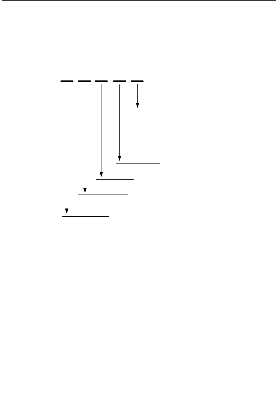
Type Codes
The type code indicates the metrology, version, base, functionality, and RF options in the
meter. The type code is found on the nameplate of the meter. The following is a depiction of
how type codes are displayed for the CENTRON OpenWay meter:
CV
SO
Meter Type
X = Third Party Comm
R = Cellrelay, 2 Zigbee (GPRS, Ethernet, GPRS+Ethernet)
D = Disconnect
(Blank) = Standard
Base Style
S = Socket
Metrology Type
V= VA
Product Family
C = CENTRON
System
O= OpenWay
C = Cellrelay, 1 Zigbee (GPRS, Ethernet, GPRS+Ethernet)
Figure 4: CENTRON OpenWay Meter Type Codes
Draft
General Information
8 CENTRON® OpenWay™ Meter Technical Reference Guide
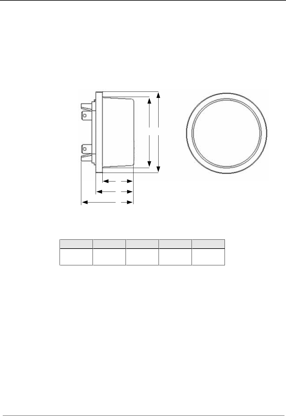
Dimensions
The following dimensional measurements are shown in inches and (centimeters).
CVSO
AB
C
D
E
Figure 5: CVSO Dimensions
A B C D E
6.29
(16.00) 6.95
(17.70) 3.84
(9.80) 4.30
(10.90) 5.67
(14.40)
Draft
General Information
CENTRON® OpenWay™ Meter Technical Reference Guide 9
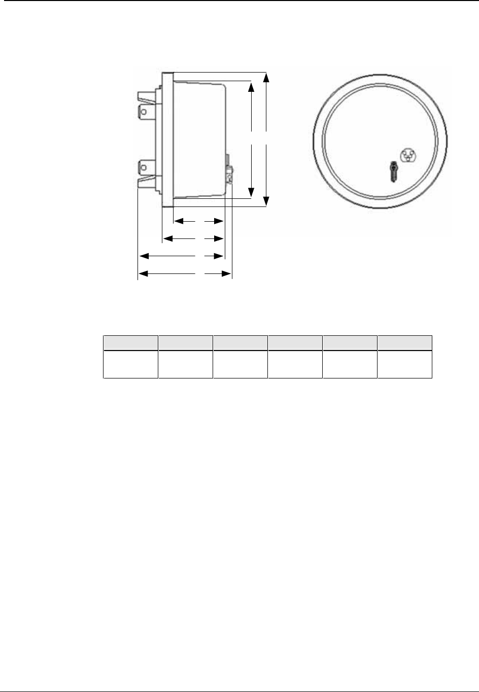
CVSOD, CVSOR, CVSOC
AB
C
D
E
F
Figure 6: CVSOD, CVSOC Dimensions
A B C D E F
6.29
(16.00) 6.95
(17.70) 3.84
(9.80) 4.30
(10.90) 5.67
(14.40) 6.11
(15.50)
Draft

General Information
10 CENTRON® OpenWay™ Meter Technical Reference Guide
Notes:
Draft

CENTRON® OpenWay™ Meter Technical Reference Guide 11
In This Chapter
Inspection.............................................................................................................11
Battery .................................................................................................................11
Storage.................................................................................................................11
Unpacking............................................................................................................12
Preliminary Inspection.........................................................................................12
Selecting a Site ....................................................................................................13
Installing the Meter into Service..........................................................................13
Retrofitting with Personality Modules.................................................................13
This chapter provides information about installing the CENTRON OpenWay meter.
Inspection
Perform the following inspections when you receive the meter:
Inspect for obvious damage to the cover, base, and meter assembly.
Compare the meter and register nameplates to the record card and invoice. Verify the
type, class, voltage, form number, and other pertinent data.
Save the original packing materials.
Battery
The CENTRON OpenWay module contains a battery that powers the clock circuit during a
power outage. The battery is permanently soldered to the module and is expected to last the
life of the meter.
Storage
Store the CENTRON OpenWay meter in a clean, dry (Relative Humidity < 50%)
environment between -40° C to +85° C (-40° F to +185° F). Avoid prolonged storage (more
than one year) at temperatures above +70° C (+158° F). Store the meter in the original
packing material.
CHAPTER 2
Installation
Draft

Installation
12 CENTRON® OpenWay™ Meter Technical Reference Guide
Unpacking
As with all precision electronic instruments, the meter should be handled with care in an
outdoor environment. Follow these precautions when handling the meter:
Avoid damaging the meter base, cover, reset mechanism (if supplied), and optical
connector (if supplied).
When handling personality modules, grip the circuit board by its edges. Do not touch
the liquid crystal display.
Save the original packing materials.
Preliminary Inspection
A preliminary inspection should be performed immediately upon receipt of your order. The
following sections suggest the minimum requirements of the preliminary inspection.
Meters Without Batteries
Upon receipt, do the following:
1 Inspect for obvious shipping damage to the cover and the meter assembly.
2 Ensure that the demand reset mechanism (optional) is secure and not damaged.
3 From the meter nameplate, verify that the information in the following table is as
specified on the original order.
Meter Type Kh Class
Voltage (Range) Service Test Amps
Form Number Frequency Serial Number
Bar Code Data Functional Options Communication Options
I/O Options
Meters With Batteries
The CENTRON OpenWay meter battery is a 3.6 volt lithium battery (TADIRAN type
5276/C).
The product you have purchased contains a battery which is recyclable. At
the end of its useful life, under various state and local laws, it may be illegal
to dispose of this battery into the municipal waste stream. Check with your
local area solid waste officials for details about recycling options or proper
disposal.
Draft

Installation
CENTRON® OpenWay™ Meter Technical Reference Guide 13
Selecting a Site
The meter is designed and manufactured to be installed in an outdoor environment, at
operating temperature ranges between -40° C and +85° C (-40° F to +185° F). Operation in
moderate temperatures increases reliability and product life.
Installing the Meter into Service
Install the meter base using standard meter installation practices.
The current and potential terminals extend as blades, or bayonets, from the back of the
meter. The meter is plugged into the socket so that the bayonets engage the main socket
jaws that connect to the service lines. Clamping pressure on the bayonets is provided by the
heavy spring pressure of the socket jaws. In some heavy-duty sockets, jaw clamping
pressure is provided by a handle or wrench.
Retrofitting with Personality Modules
CENTRON OpenWay meters can be upgraded to increase functionality by changing the
Personality Modules.
Do not power ON the meter without the inner cover in place. Power
the meter OFF before removing the inner cover. Personality modules
are sensitive to ESD damage. Take appropriate grounding measures
before retrofitting!
To change or add a Personality Module:
1 De-energize the meter.
2 Remove the outer cover.
3 Remove plastic inner cover by holding the meter with both hands and applying equal
pressure on either side of the three and nine-o’clock positions. The inner cover is held in
place by four plastic tabs on the meter base.
4 Remove the black board-to-board connector (M in the figure below) between the
circuit board and the metrology board by pulling it by its middle while moving it side-
to-side. To maintain the integrity of the connector, only remove it when you are
upgrading the meter.
5 Remove the register module, one side at a time, by pulling gently outward on the meter
frame snaps (N in the figure above) while lifting the module up.
6 Snap the new module into the meter frame by aligning the notches at bottom of the
circuit board with the lower two snaps.
Draft

Installation
14 CENTRON® OpenWay™ Meter Technical Reference Guide
The module must be aligned properly in the snaps to avoid damaging
the connector or circuit board.
7 Replace the board-to-board connector by aligning the top of the connector with the
notches in the circuit board and pressing gently at the bottom of connector to mate the
connector to metrology board. Then, gently press the top of the connector to mate it to
the register module. The connector is seated correctly when you hear it snap into place.
Be sure to use the meter base for leverage instead of the LCD holder.
Pressure on the LCD holder may damage the personality module.
8 Ensure the board-to-board connector is fully seated by pressing firmly in on the middle
of the connector.
9 Carefully replace the inner protective cover. Engage the top snaps first, taking care to
place the slot at the top of the cover over the IR light pipe. Failure to do so could break
the light pipe. Ensure that all four meter base tabs are engaged with the slots at the top
and bottom of the inner cover.
10 Place the cover over the meter base until the flange on the cover is flush with the flange
on the meter base.
11 Turn the cover clockwise until the locking tabs are fully engaged with the meter base.
Draft

CENTRON® OpenWay™ Meter Technical Reference Guide 15
In This Chapter
Metrology ............................................................................................................15
Surge Protection...................................................................................................16
Sampling..............................................................................................................16
Voltage and Current Measurement......................................................................17
Watthour (Wh) Measurement ..............................................................................17
Volt-amperehour (VAh) Measurement................................................................18
Demand Calculations...........................................................................................18
Metrology
The CENTRON OpenWay meter is a solid-state meter which uses the Hall Effect (one per
phase) to measure metered current and voltage dividers (one per phase) to measure metered
voltage as indicated in block diagram below.
Figure 7: CENTRON OpenWay Metrology
The metrology performs the direct sampling of the voltage and current waveforms and the
raw processing of these samples to compute all the energy quantities. It is comprised of a
dedicated microprocessor and an analog-to-digital (A/D) converter. Low level signals
proportional to the service voltages and currents are connected to the analog inputs of the
A/D converters. These converters, which are contained in one package, individually sample
the signals and send the digital results to the microprocessor 1,920 times per second. The
microprocessor takes these samples, applies precision calibration corrections and computes
all the quantities required for the specific meter configuration.
CHAPTER 3
Operation: Base Metrology
Draft
Operation: Base Metrology
16 CENTRON® OpenWay™ Meter Technical Reference Guide
Surge Protection
Surge protection for the electronics in the CENTRON OpenWay meter is provided by Metal
Oxide Varistors (MOVs). MOVs are clamping devices that allow voltage up to a limit, and
then increasingly conduct current to prevent the voltage from exceeding the limit. The
MOVs on the power supply board are connected directly across the voltage inputs to the
meter. Although this approach requires very large MOVs, it prevents high voltages from
appearing on or near the electronic boards giving the CENTRON OpenWay meter superior
performance when exposed to extremely high-voltage surges.
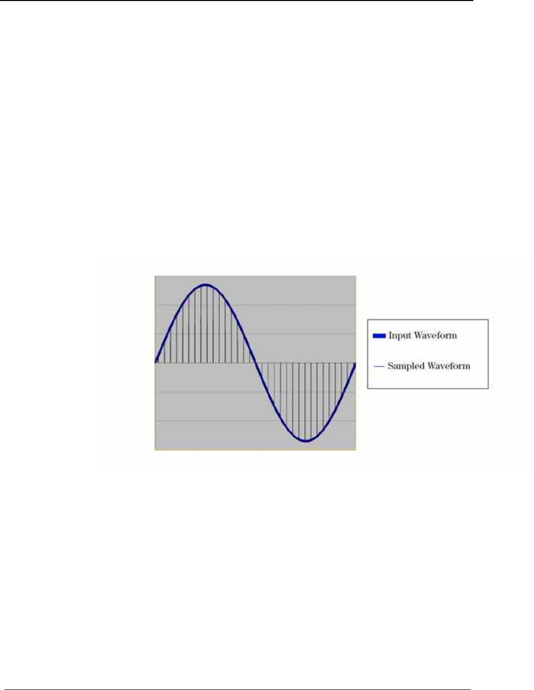
Sampling
The analog-to-digital converter samples each phase voltage and current signal (independent
of the line frequency) and sends the digital values immediately to the microprocessor. Each
time a new set of digital samples are received by the microprocessor, it calculates all of the
selected metrological quantities.
Figure 8: Sampled Waveform
At this sampling rate, harmonics to the 15th are measured. The high rate of the sampling
enables the CENTRON OpenWay meter to measure energy quantities accurately under high
harmonic distortion conditions. The sampling continues uninterrupted as long as the meter is
powered up. All other processing is done in the background between samples. From the
continuous train of digital samples on each of the six channels, current, voltage, active
energy, reactive energy, and apparent energy quantities are computed.
Draft

Operation: Base Metrology
CENTRON® OpenWay™ Meter Technical Reference Guide 17
Voltage and Current Measurement
Figure 9: Voltage and Current Measurement
Watthour (Wh) Measurement
Watt-hours are measured by multiplying the instantaneous value of the voltage on each
phase times the instantaneous value of the current on the same phase.
The resulting values are added to the Wh accumulator. After the completion of two cycles,
the registers are compared to a threshold. This threshold represents 0.025 watt-hours. The
value in the accumulator is then divided by this threshold, and the registers are updated
accordingly. This means that under bidirectional measurement, if the consumption changes
from delivered to received within one second, the meter will respond correctly to the change
and accumulate in both the delivered and received registers. The CENTRON OpenWay
meter can be programmed to register watt-hours either in the delivered quadrants only, or
under bidirectional measurement, in the delivered and received quadrants. When only
delivered watt-hours are measured, any negative watthour value is ignored. This has the
same effect as a detent mechanism on an induction watthour meter.
When delivered and received watt-hours are measured, there will be one register for each
quantity available—Wh delivered and Wh received, as well as one combined register—Wh
net.
Draft

Operation: Base Metrology
18 CENTRON® OpenWay™ Meter Technical Reference Guide
Volt-amperehour (VAh) Measurement
The CENTRON OpenWay meter measures either Vectorial or RMS volt-amperes using
arithmetic phase summation. The arithmetic method of measurement ensures that the
resulting VAh value contains as much of the harmonic information as possible.
Volt-ampere values are calculated by multiplying the RMS voltage value times the
coincident RMS current value.
The voltage and current values from each phase are squared and then stored in their
respective accumulators. At the end of one second, each accumulator contains the sums of
the square of the voltages or currents for each phase. The contents of these accumulators
are passed to the consumption routine where they are averaged (divided by the sample
count) and the square root is taken, yielding the RMS voltage and RMS current for each
phase.
Every second the RMS voltage and the RMS current for each phase are multiplied together
to establish a VA-second value for each phase. These values are scaled and corrected.
The total VAhour value is calculated by adding the VA-second quantities for each phase and
dividing the total by 3600. This value is added to the appropriate register. If the harmonics
on the Voltage waveform differ from the harmonics on the Current waveform, then the
harmonic energies will fall out of the Watthour and Varhour calculation, and thus the VA
Vectorial measurement, but they will not fall out of the VA Arithmetic measurement.
The VA Vectorial and VA Arithmetic measurements will also differ when there is
imbalanced power. Imbalanced power is generated when the phases of the service are not in
balance with one another.
Demand Calculations
To calculate demand, the selected quantities are accumulated over a programmable time
period (1, 2, 3, 4, 5, 6, 10, 12, 15, 20, 30, or 60 minutes) depending on the programmed
demand interval length. At the end of the interval, the accumulated values are stored in
separate demand storage registers and the accumulating registers are cleared. Incremental
values for the next demand interval are then accumulated.
The maximum demand in a billing period is determined by comparing the demand values
for the most recently completed interval to the respective readings presently stored in the
peak demand registers. If the previous demand is greater than the value in the
corresponding peak demand register, the lower value (the maximum demand recorded so
far) is replaced. If the previous demand is less than the value in the corresponding peak
demand register, the maximum demand value remains unchanged. This update process is
carried out when a demand interval is completed, when a power outage occurs, when Test
Mode is initiated, or when a Real Time Rate change occurs.
The CENTRON OpenWay meter demand calculations are performed using one of two
possible methods: block or rolling. The demand method is selected when the register is
programmed.
Draft

Operation: Base Metrology
CENTRON® OpenWay™ Meter Technical Reference Guide 19
Block Interval Demand Calculation
Block Demand calculations are based on user-defined interval lengths. The demand is the
total energy accumulated during the interval divided by the length of the interval. At each
end of interval (EOI), demand calculations are made and “EOI” can be displayed on the
LCD.
For block interval, demand calculations are made at the end of each completed demand
interval. This method is similar to the way mechanical demand meters operate. As load is
applied to the demand register, an indicating pointer and maximum demand indicator are
driven upscale. At the end of each interval, the indicating demand pointer is returned to the
zero position, and the maximum demand pointer retains its highest or maximum position.
Rolling/Sliding Demand Interval Calculation
A selected number of subintervals make up the demand interval. At the end of each
subinterval, new demand calculations occur based on the last full demand interval and
“EOI” can be displayed on the LCD.
See Demand Registers (on page 38) for a list of the quantities that can be selected for rolling
demand.
Block interval demand calculation is subject to peak splitting, whereby it is possible for an
electricity consumer to manipulate the load for limited periods within the demand interval.
The registered demand reading will be less than the actual maximum demand of the load.
To counter this situation, the concept of rolling demand was introduced. Rolling demand is
calculated as follows:
1 For illustration purposes, assume a 15 minute billing demand interval with three five-
minute subintervals has been selected. Then, at any given moment, the meter has three
complete sets of five-minute information available for demand calculations.
2 At the end of the present five-minute subinterval, the information on the oldest five-
minute subinterval is discarded, and demand calculations are performed on the three
newest sets of subintervals. In this manner, the CENTRON OpenWay meter with the
rolling demand option updates the demand calculations every five minutes.
3 If the billing demand interval is 30 minutes with five-minute subintervals, then six sets
of five-minute information or updates will be used for calculating previous demand.
Cumulative Demand Values
Cumulative Demand is the summation of previous maximum demands after each demand
reset. When a demand reset occurs, the maximum demand values are added to the existing
corresponding cumulative demand values, and the sums are saved as the new cumulative
demands. These values will not increase until the next demand reset. This feature not only
protects the user from false or erroneous readings, but also provides the customer with extra
security against tampering. Cumulative demand may be used for block, rolling and thermal
demand types.
Draft

Operation: Base Metrology
20 CENTRON® OpenWay™ Meter Technical Reference Guide
Continuous Cumulative Demand Values
Continuous Cumulative Demand is the sum of the maximum demand and the cumulative
demand at any point in time. At the end of each demand interval, if a new maximum
demand is reached, continuous cumulative demand will also be adjusted to reflect this new
maximum demand value. A demand reset will clear the maximum demand value, but will
not affect the continuous cumulative demand. Continuous cumulative demand may be used
for block, rolling and thermal demand types.
Present Demand
Present Demand is the value that would be used if an EOI were to occur when the data is
being viewed. It is calculated by dividing the accumulated energy in the current interval by
the time of a full interval. For block demands, present demand starts at zero for each interval
and ramps up to the demand value at the EOI. For rolling demands, the energy from the
oldest subinterval is discarded and the present demand is calculated using the energy in the
remaining subintervals and the energy in the current subinterval. At the beginning of a new
subinterval, it drops by the demand of the oldest subinterval and ramps up to the demand
value at the next EOI.
Present demand is not affected by a demand reset.
Previous Demand
Previous Demand is the demand from the most recently completed demand interval. When a
demand interval ends, the present demand is transferred to the previous demand. When
using rolling demand, this quantity is updated after each subinterval.
Peak Demand (Maximum Demand)
Peak Demand is the largest demand value that has occurred during any demand interval
since the last demand reset. At the end of a demand interval, the present demand is
compared with the current maximum demand register. If the present demand is greater, it is
transferred to the maximum demand. The maximum demand is reset to zero on a demand
reset. The date and time of the maximum demand are also recorded. Maximum demand is
used for block, rolling, and thermal demand types.
Demand Thresholds
The table below describes parameters that define the configuration of demand thresholds. A
threshold is a value against which a meter quantity is compared. If the quantity is beyond
the threshold, an alarm is generated.
Draft

Operation: Base Metrology
CENTRON® OpenWay™ Meter Technical Reference Guide 21
Threshold Alarm Parameters
Parameter Description
Quantity Selects the demand register to which this threshold will
apply.
Threshold Value Sets the limit for this threshold event to be activated.
• The valid range for Power Factor (PF) is 0.0 - 1.0
• For all others, the valid range is 1.0 - 500.000
Coincident Demand
Coincident Demand is the energy accumulated in an interval where a second trigger energy
attained a peak. For example, Var demand when Watt demand attained a peak. Coincident
demands are programmable.
Draft

Operation: Base Metrology
22 CENTRON® OpenWay™ Meter Technical Reference Guide
Notes:
Draft

CENTRON® OpenWay™ Meter Technical Reference Guide 23
In This Chapter
Controls and Indicators........................................................................................24
Factory Reset .......................................................................................................28
Application of Power and Power-up....................................................................28
Power Down Procedures......................................................................................28
Operating Modes .................................................................................................29
Display Modes.....................................................................................................30
Registers ..............................................................................................................37
Interrogation and Programming...........................................................................39
Time-of-Use (TOU).............................................................................................40
Load Profile .........................................................................................................43
Event Log.............................................................................................................46
Security Codes.....................................................................................................48
Firmware Upgrades..............................................................................................50
R300CD/CD3 ......................................................................................................50
Testing, Troubleshooting, and Maintenance........................................................52
This chapter describes the basic operation of the CENTRON OpenWay meter register
operation. It also explains how to configure the OpenWay register while providing detailed
information on energy and demand functions, as well as Time of Use (TOU), Load Profile,
and communications board options.
Figure 10: CENTRON CVSO Meter
CHAPTER 4
Operation: CVSO OpenWay Register
Draft

Operation: CVSO OpenWay Register
24 CENTRON® OpenWay™ Meter Technical Reference Guide
Controls and Indicators
All controls and indicators are shown in the figure below.
Figure 11: Controls and Indicators
Callout Description
M Liquid Crystal Display (LCD)
N Magnetic Switch
O Demand Reset Button
P Test Mode Button
Q Optical Port
R Infrared Test LED
S Nameplate
Infrared Test LED
One infrared (IR) LED is located at the 3 o’clock position of the meter nameplate. The LED
can be configured to pulse based on any of the following energy quantities:
Wh delivered, received
VAh delivered, received (arithmetic or vectorial)
Draft
Operation: CVSO OpenWay Register
CENTRON® OpenWay™ Meter Technical Reference Guide 25
Liquid Crystal Display (LCD)
The CENTRON OpenWay meter features a versatile ANSI C12.10-compliant, 104-segment
liquid crystal display (LCD). The LCD with all segments lit is shown in the figure below.
There are several static indicators available on the LCD as described in the table below the
figure.
Figure 12: CENTRON OpenWay LCD
Static Indicators
Indicator Description
Load Emulator (-> for positive, <- for negative)
888 888888 Nine digits (7 segments each) for display of
alphanumeric information
120 240 Nominal Voltage Indicator (one value appears at a time)
EOI End of Interval (Registers - Dmd)
Scr Loc Scroll Lock (indicates temporary scroll lock of a display
item)
nor diSP Entry into Normal Mode.
TEST Entry into Test Mode.
The indicators shown in the table above actually display in a digital readout font;
some characters may display as upper case.
Draft
Operation: CVSO OpenWay Register
26 CENTRON® OpenWay™ Meter Technical Reference Guide
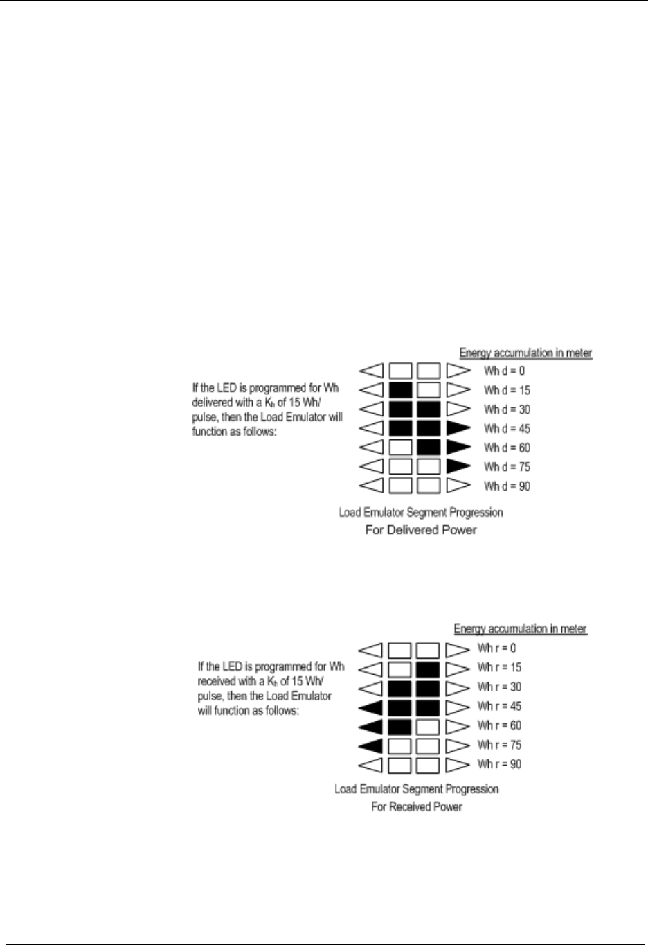
Load Emulator
The Load Emulator follows the Infrared Test LED. For each pulse of the Test LED, the
Load Emulator increments one segment. The operation of the Load Emulator depends on the
quantity being pulsed.
If the quantity being pulsed is “Delivered-Only”, then the Load Emulator scrolls to the
right when energy is being delivered and lights the left arrow when energy is being
received.
If the quantity being pulsed is “Received-Only”, then the Load Emulator scrolls to the
left when energy is being received and lights the right arrow when energy is being
delivered.
If the quantity being pulsed is “Delivered and Received”, then the Load Emulator
scrolls to the right when energy is being delivered and scrolls to the left when energy is
being received.
The figures below represents a typical progression of the Load Emulator segments:
Figure 13: Load Emulator Segment Progression for Delivered Power
Figure 14: Load Emulator Segment Progression for Received Power
Draft
Operation: CVSO OpenWay Register
CENTRON® OpenWay™ Meter Technical Reference Guide 27
Several uni-directional quantities are available. When these quantities are
programmed to LED, both the LED and the load emulator will function for
delivered and received quantities.
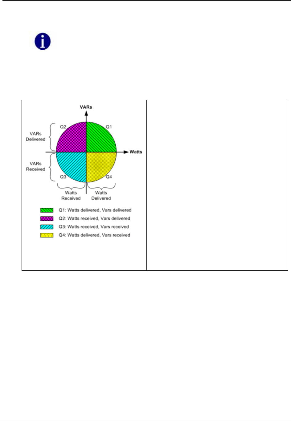
Power Circle Quadrants
The following power circle diagram shows the quadrants for watts and vars delivered and
received.
Figure 15: Power Circle Diagram
The directional calculations in the CENTRON
OpenWay meter are as follows:·
• Watts delivered = (wattsQ1) + (wattsQ4)·
• Watts received = (wattsQ2) + (wattsQ3)·
• VA delivered = (VA while watts are in Q1) + (VA
while watts are in Q4)·
• VA received = (VA while watts are in Q2) + (VA while
watts are in Q3)·
Optical Port
The optical port is mounted on the meter cover. The optical port is a communication
interface from the meter to a PC. Interface to a PC is accomplished through a
communication cable which attaches to the optical port on one end and a PC serial port on
the other end. This interface cable can be powered by a DC TAP, an AC Adaptor, or the
PC’s COM Port. Communication through the optical port may be at 9600, 14400, 19200, or
28800 bps.
Draft

Operation: CVSO OpenWay Register
28 CENTRON® OpenWay™ Meter Technical Reference Guide
Factory Reset
To return the meter to its original factory settings, you must perform a factory reset. A
factory reset is also referred to as a “three button reset”.
All programming of the meter will be lost when a factory reset is performed.
All security codes are also cleared.
When you perform a factory reset, the original factory settings of the meter are restored.
Application of Power and Power-up
To energize all electronics, apply 240V (50/60 Hz).
Do not power up the meter if the upper and lower housing are not
properly secured. Line-level voltages are present inside the housings.
Failure to follow this procedure could result in serious personal injury
or death.
Power Down Procedures
To de-energize all electronics, remove power from the meter.
A power outage is recognized any time the line voltage drops 20 percent below the lowest
nominal point of the voltage range. With a standard single phase power supply, a power
outage occurs when line voltage drops below XX volts; with a OpenWay power supply, a
power outage occurs when line voltage drops below XX volts. When a power outage is
recognized, the OpenWay Register saves all billing values to non-volatile Flash memory.
Demand Meter
Restoration of AC power energizes the electronics and causes the meter to perform self-
diagnostic check procedures. The meter then retrieves all billing data from non-volatile
memory, begins measuring energy, and starts the process of calculating any demand values.
TOU/Load Profile Meters
All OpenWay meters have a battery installed. The battery allows the TOU and Load Profile
data in RAM to be maintained during a power outage. The battery also allows the
timekeeping circuitry in the meter to maintain the meter's clock during an outage. If a
battery is removed on a TOU/Load Profile meter during an outage, then the meter's clock
will be off by the duration of the outage and the TOU data and some Load Profile data will
be lost. Load Profile data is periodically committed to flash as described in the Load Profile
section.
Draft

Operation: CVSO OpenWay Register
CENTRON® OpenWay™ Meter Technical Reference Guide 29
Upon the return of AC power, the register undergoes a procedure similar to the initial
power-up. The meter performs self-diagnostic checks, data is retrieved from non-volatile
memory, and normal operation is resumed. The number of minutes of power outage
maintained while the meter was in carry-over operation, is added to the Time on Battery
register. Since the demand interval is synchronized to the top of the hour, the first demand
interval after a power outage may be shorter than the programmed interval value.
Cold Load Pickup
Normally, when power is restored to the meter after an outage, a new demand interval is
started and demand calculations begin immediately. The meter can be configured to
recognize a demand delay or cold load pickup (CLPU) time. If a CLPU is configured in the
meter, the meter will delay demand calculations for the configured amount of time—0 to
255 minutes in one-minute increments. For example, if a CLPU time of five minutes is
programmed into the meter, a power outage will cause the meter to wait five minutes after
power restoration before resuming demand calculations.
Defining CLPU as zero will cause demand calculations to restart immediately after
any recognized power outage.
Interval Make-up
During power-up processing, the Load Profile component checks if the duration of the
outage exceeds the configured minimum duration time. If it does, then at least one interval
will be tagged with an outage status. The interval that was active when outage occurred is
tagged as a partial interval due to the outage. If the outage ended in the middle of another
interval, then that interval is also tagged as a partial interval due to the outage. If any
intervals occurred in between, then those intervals are tagged as skipped intervals due to the
outage and their data will be all zeroes.
Operating Modes
The OpenWay Register has two operating modes: Normal Mode and Test Mode.
When the meter is placed in Test Mode, it ceases all normal billing functions. The
TEST switch can be used to control the operating mode of the OpenWay Register.
Normal Mode
Normal Mode is the standard mode of operation and the mode in which the meter
automatically starts when energized. Selected quantities are measured and processed in
billing registers. During this mode of operation, billing registers are saved in non-volatile
memory during power outages.
Draft

Operation: CVSO OpenWay Register
30 CENTRON® OpenWay™ Meter Technical Reference Guide
Test Mode
The meter can be placed into Test Mode through software communications.
While in Test Mode, the “TEST” annunciator is displayed on the LCD. When the Test
Mode is activated, all billing registers and certain non-billing registers are preserved in non-
volatile memory and restored when Test Mode is exited.
Test Mode Timeout
If the meter is left in Test Mode, the meter will automatically exit after a user-configurable
Mode Timeout. This action prevents someone from accidentally leaving a meter in Test
Mode and thus losing billing data.
Display Modes
The OpenWay Register has five display modes as shown in the table below: Normal,
Alternate, Test, Test Alternate, and Toolbox. Each display mode has a separate list of items
(quantities) it can display. The aggregate of items associated with a display mode is called a
display list. Test and Test Alternate modes employ the same display list. The CENTRON
OpenWay meter can display a maximum of 80 items. The display list is dynamically
configured through PC-PRO+ Advanced. The user can select as many items per mode
totaling up to 80 with at least one item in each display mode. The display items and
sequence of display, along with any desired annunciators or ID code number, are selected
during program setup, a feature of the PC-PRO+ Advanced programming software.
Operating Mode Display Mode Metrological LED Quantity
Normal
Normal
Alternate
Toolbox
Normal Mode Quantity
Alt Mode Quantity
Normal Mode LED
Selection
Test Test
Test/Alternate
Test Mode Quantity
Test Alt Mode Quantity
The following types of displayable items are available for the user-defined display lists:
Energy registers
Demand registers
Instantaneous registers
Self Read registers
SnapShot registers
Informational items (configuration, state informational items)
Numerical values may be displayed in various formats depending on configuration. For
example, kilo units, mega units, fixed decimal point, floating decimal point, and leading
zeros can all be configured.
The following tables show items programmable for display in the modes indicated.
Draft

Operation: CVSO OpenWay Register
CENTRON® OpenWay™ Meter Technical Reference Guide 31
All of the display items in the next two tables may be selected by TOU Rate. They also may
be selected from the four Self Read buffers, the two Demand Reset Snapshot buffers, and
Last Season Self Read buffer.
Energy Data Display Items
Display Mode
Energy Data Display Item Normal
Alternate Test
Toolbox 1
Wh (delivered, received, net, uni-
directional) X X X
Varh (delivered [lag], received [lead], Net,
net delivered, net received, Q1, Q4) X X X
VAh (delivered, received; arithmetic &
vectorial) X X X
VAh lag (vectorial) X X X
Qh (delivered, received) X X X
Vh (Phase A, Phase B, Phase C,
Average) X X
Ah (Phase A, Phase B, Phase C) X X
V2h Aggregate X X
A2h Aggregate X X
Demand Data Display Items
Display Mode
Demand Data Display Item Normal
Alternate Test
Toolbox2
W Delivered (Max, Present, Previous,
Projected, Cumulative, Continuous
Cumulative) X X X
W Received (Max, Present, Previous,
Projected, Cumulative, Continuous
Cumulative) X X X
W Net (Max, Present, Previous, Projected,
Cumulative, Continuous Cumulative) X X X
W Uni-directional (Max, Present, Previous,
Projected, Cumulative, Continuous
Cumulative)
Var Q1, Var Q4 (Max, Present, Previous,
Projected, Cumulative, Continuous
Cumulative) X X X
Var Delivered [lag: Q1+Q2] (Max, Present,
Previous, Projected, Cumulative,
Continuous Cumulative) X X X
Var Received [lead: Q3+Q4] (Max,
Present, Previous, Projected, Cumulative,
Continuous Cumulative) X X X
Draft

Operation: CVSO OpenWay Register
32 CENTRON® OpenWay™ Meter Technical Reference Guide
Display Mode
Demand Data Display Item Normal
Alternate Test
Toolbox2
Var Net
VA Delivered [arithmetic or vectorial] (Max,
Present, Previous, Projected, Cumulative,
Continuous Cumulative) X X X
VA Received [arithmetic or vectorial] (Max,
Present, Previous, Projected, Cumulative,
Continuous Cumulative) X X X
VA Lag (Max, Present, Previous,
Projected, Cumulative, Continuous
Cumulative) X X X
Max A (per phase: A, B, C) X X
PF Average X X
Min P.F. X X
Coincident Demands (up to 4) X X
Instantaneous Data Display Items
Display Mode
Instantaneous Data Display Item Normal
Alternate Test
Toolbox3
Instantaneous W X X X
Instantaneous Var X X X
Instantaneous VA (arithmetic & vectorial) X X X
Instantaneous Volts (A, B, C) X X X
Instantaneous Amps (A, B, & C) X X X
Instantaneous P.F. X X
Instantaneous Frequency (Hz) X X
Instantaneous Current Phase Angles (A, B, C)
X
Instantaneous Voltage Phase Angles (A, B, C)
X
Informational Data Display Items
Display Mode
Informational Data Display Item Normal
Alternate Test
Toolbox4
Calibration Date & Calibration Time X X
Cold Load Pickup Outage Time X X
Current Transformer Ratio X X
Current Date, Day & Current Time X X
Days Since Demand Reset X X
Demand Reset Count X X
Draft

Operation: CVSO OpenWay Register
CENTRON® OpenWay™ Meter Technical Reference Guide 33
Display Mode
Informational Data Display Item Normal
Alternate Test
Toolbox4
Diagnostic Counters 1-4
X
Display On Time X X
Firmware Revision X X
Last Outage Date & Last Outage Time X X
Last Program Date & Last Program Time X X
Last Reset Date & Last Reset Time X X
Last Test Date & Last Test Time X X
Load Profile Pulse Weight 1-8 X X
Load Research ID X X
Last Season Self Read Registers X X
Meter ID & Meter ID 2 X X
Minutes on Battery X X
Normal Kh & Normal Kh #2 (Alternate Kh) X X
Number of Subintervals X X
Number of Test Subintervals
X
Last Interrogate Date & Time X X
Option Board Fields 1 - 3 X X
Outage Count X X
Program Count X X
Program ID X X
Register Fullscale X X
Register Multiplier X X
RF ID 1-3 X X
Segment Test X X
Service Type X X
SiteScan Diagnostic Count X
Software Revision Number X X
Subinterval Length X X
Test Kh & Test Kh #2 (Test Alternate Kh)
X
Test Subinterval Length
X
Time Remaining in Demand Subinterval X X X
Time Remaining in Test Mode
X
TOU Expiration Date X X
Draft

Operation: CVSO OpenWay Register
34 CENTRON® OpenWay™ Meter Technical Reference Guide
Display Mode
Informational Data Display Item Normal
Alternate Test
Toolbox4
Transformer Ratio X X
User Data 1-3 X X X
Voltage Transformer Ratio X X
Magnetic Switch
The magnetic switch enables scroll lock of display items as well as manual switching
between display modes. The magnetic switch is located near the front of the meter face in
the 9 o’clock position.
Scroll Lock
When the magnetic switch is activated for one second and removed, the “ScrLoc” message
appears on the LCD and the display locks on the current display item. The value displayed
on the locked screen will continue to be updated every second. The user may scroll to the
next item by again momentarily activating the magnetic switch. The display will remain in
the scroll lock condition until a mode timeout occurs or until the display mode is changed.
Changing Display Modes
When the magnetic switch is activated for four seconds, the display may indicate the
“ScrLoc” condition (if not already in scroll lock) and then, enter into a display mode
selection menu. The menu options are: “SELnor”, “SELALt”, and “SELtooL”. The desired
mode can be selected by removing the magnet when it is being displayed.
Mode Timeout
When the display is put into display modes other than Normal display (Alternate, Toolbox,
Scroll Lock, Test, or Test Alternate display modes), the meter will return to normal
operation after a programmable Mode Timeout expires. The Mode Timeout can be
configured from 1 to 255 minutes using the meter programming software.
Normal Display Mode
The Normal Display Mode is the default display when the meter is energized and when the
meter is in Normal Operating Mode. When Mode Timeout occurs from any other display
mode, the display returns to Normal Display Mode.
Alternate Display Mode
The Alternate Display Mode is functionally identical to the Normal Mode. The meter itself
still operates under normal measurement, but the display sequence can be programmed to
show a different set of displayable items from those in the Normal Display Mode.
Draft

Operation: CVSO OpenWay Register
CENTRON® OpenWay™ Meter Technical Reference Guide 35
While in Alternate Display Mode, the “ALT” annunciator on the lower left of the display
designates activation of the Alternate Display Mode. Upon completion of the Mode Time-
out period, the meter automatically returns to the Normal Display Mode.
Toolbox Display Mode
Toolbox Display Mode is identical to Normal Mode except that the list of displayable items
is a fixed list dependent on the service type.
You can enter the Toolbox Mode from either Normal or Alternate Mode. While in Toolbox
Mode, a flashing “TEST” appears on the right side of the display.
Once activated, the Toolbox Mode scrolls through the list of per-phase items and diagnostic
counters. The table below shows an example of a 3-element meter.
Description Display
Phase A voltage angle PhA 0.0° U
Phase A voltage PhA xxx.x U
Phase A current angle PhA xxx.x° A
Phase A current PhA xxx.x A
Phase B voltage angle PhB xxx.x° U
Phase B voltage PhB xxx.x U
Phase B current angle PhB xxx.x° A
Phase B current PhB xxx.x A
Phase C voltage angle PhC xxx.x° U
Phase C voltage PhC xxx.x U
Phase C current angle PhC xxx.x° A
Phase C current PhC xxx.x A
# of Diagnostic 1 errors d1 xxx
# of Diagnostic 2 errors d2 xxx
# of Diagnostic 3 errors d3 xxx
# of Diagnostic 4 errors d4 xxx
All “PhA”, “PhB”, “PhC” quantities are displayed with a fixed decimal and no
leading zeros. While displaying phase information, the load emulator cycles at a
fixed rate in the direction of energy flow for that phase. The Load Emulator is not
displayed while the diagnostic counters are displayed. The diagnostic counters are
displayed with leading zeros (000-255).
Draft

Operation: CVSO OpenWay Register
36 CENTRON® OpenWay™ Meter Technical Reference Guide
The per-phase Volt and Amp readings are Root-Mean-Square (RMS) values which are
updated every second. The voltage and current angles are updated every five seconds. The
direction of the load emulator is the same as the direction of energy flow for the phase being
displayed. If any quantity is undefined due to the meter’s service, the per-phase information
for that quantity will not be displayed.
If the magnitude of the current for that phase is too low, the current magnitude and angle for
a particular phase (A, B, or C) are displayed as zeros.
The SiteScan diagnostic counters represent the number of times each diagnostic error
occurred since the last time the counters were reset.
The diagnostic counters range from 0 to 255 and can only be reset to zero through the
PC-PRO+ Advanced programming software.
Upon completion of the Mode Timeout period, the meter automatically returns to the
Normal Display Mode.
Test Display Mode
The Test Mode can be accessed from either the Normal, Alternate, or Toolbox Mode by
removing the meter cover and pressing the Test button.
To activate this mode with a programming device, refer to the appropriate software user’s
manual.
The Test Mode annunciator (“TEST”) is displayed while the D/T/L Register is in Test
Mode.
Activating Test Mode causes all billing data to be transferred to non-volatile memory. Upon
entry of Test Mode, if any calculated demand values of the present interval are higher than
the stored maximum demand values, the new values are stored as maximum demands. All
Test Mode program parameters are then retrieved from non-volatile memory for use in Test
Mode. The parameters are demand test interval length, number of subintervals, and test Kh.
Each is independent from those specified for Normal Mode. Activating the demand reset
while in Test Mode initializes the demand test interval. (This interval is not synchronized to
the top of the hour.)
To exit Test Mode and place the register in Normal Mode, perform one of the following:
Press and then release the manual Test Mode button a second and a third time. The
“TEST” annunciator will go away.
Wait for selected Test Mode timeout to occur; if the meter is inadvertently left in Test
Mode, it will return to Normal Mode at the completion of Mode Timeout.
Removal of power for a brief period will force Test Mode to end.
Values calculated in Test Mode are not added to previous billing values or stored for
retrieval. After exiting Test Mode, all billing data previously transferred to non-volatile
memory is retrieved, an end-of-interval (EOI) is initiated, and a new demand interval
begins.
Draft

Operation: CVSO OpenWay Register
CENTRON® OpenWay™ Meter Technical Reference Guide 37
Any time-related activities, such as TOU rate changes or Daylight Savings Time (DST)
changes that occur while the meter is in Test Mode, are performed upon exiting Test Mode.
Test Alternate Display Mode
Test Alternate Mode is functionally identical to Test Mode. To enter Test Alternate Mode,
press the Test switch a second time. The “TEST” and “ALT” annunciators will be
displayed. The meter will return to Normal Mode at the completion of Mode Time-out.
Diagnostic Displays
The user may program the behavior that the meter should exhibit for every specific error
condition. The possible actions in order of increasing severity are to ignore the error (do not
display the error code); scroll its error code (an error code is automatically displayed after
each display item); or lock the display, showing only the error code (do not display anything
else).
Registers
There are five register types in the D/T/L Register: Energy, Demand, Instantaneous, Self
Read (or Snapshot), and Information.
Energy Registers
The D/T/L Register can measure numerous energy quantities (as shown in the table below)
from which the user can configure any eight to be registered.
If an energy register that is being used in the Load Profile is edited, the current interval
for that quantity will be affected.
Measured Energy
Quantity Type Phases Directions
watt-hours aggregate delivered
received
net
uni-directional
Varhours aggregate delivered
received
net
net delivered
net received
Q1, Q4
VA-hours (vectorial or arithmetic [RMS]) aggregate delivered
received
lagging
Draft

Operation: CVSO OpenWay Register
38 CENTRON® OpenWay™ Meter Technical Reference Guide
Measured Energy
Quantity Type Phases Directions
Volt-hours (Vh) phase A
phase B
phase C
average
Amp-hours (Ah) phase A
phase B
phase C
V2h aggregate
A2h aggregate
Q-hours aggregate delivered
received
Demand Registers
Demands can be calculated from any of the eight selected energy quantities. The user can
configure up to ten demand registers. The D/T/L Register can compute three types of
demand: Block Demand, Rolling Demand, or Thermal Demand.
Measured Demand
Quantity Type Demand Registers Phases Directions
watt-hours Block, Rolling,
Thermal aggregate delivered
received
net
uni-
directional
Varhours Block, Rolling,
Thermal aggregate delivered
received
net
per
quadrant
VA-hours (vectorial or
arithmetic [RMS]) Block, Rolling,
Thermal aggregate delivered
received
lagging
Amp-hours (Ah) Block phase A
phase B
phase C
Draft

Operation: CVSO OpenWay Register
CENTRON® OpenWay™ Meter Technical Reference Guide 39
Instantaneous Registers
The D/T/L Register is capable of displaying Primary or Secondary Instantaneous registers,
with the following exceptions: Frequency, Power Factor (PF), and Phase Angles. The user
can configure the CT and VT multipliers (transformer ratios) using PC-PRO+ Advanced
programming software.
Instantaneous Register
Quantity Directions (Types) [Range] Phases
W Signed (+) Delivered or (-)
Received Aggregate
Var Signed (+) Delivered or (-)
Received Aggregate
VA
(Vectorial or
Arithmetic)
None Aggregate
V None A, B, C
A None A, B, C
PF None Average
Frequency None A
Phase Angles Va = 0° Vb, Vc, Ia, Ib, Ic
Self Read and Snapshot Registers
There are up to fifteen self-read registers available in the D/T/L Register, depending on the
particular version. All meters have two snapshot registers that store self read data triggered
by a demand reset. Snapshot 1 is taken at the most recent demand reset. Snapshot 2 is the
next most recent set of self read data at demand reset. Meters with time keeping
functionality have an additional twelve self-reads registers used for scheduled self-reads,
and one Last Season self-read register triggered at a season change in TOU meters.
Information Registers
The D/T/L Register also stores a significant amount of informational data. These non-
registered values are listed in Informational Data.
Interrogation and Programming
Interrogation
The meter can be interrogated via the ANSI C12.18 optical port using PSEM (ANSI
C12.18-1996) protocol.
Draft

Operation: CVSO OpenWay Register
40 CENTRON® OpenWay™ Meter Technical Reference Guide
Programming
The software for programming this meter (PC-PRO+ Advanced) is a 32-bit Windows
NT/2000/XP application. User-definable security codes in both the programming software
and the meter prevent unauthorized access to the meter.
Programming and/or interrogation of the meter can be accomplished through the optical port
using a laptop PC and an optical probe.
Time-of-Use (TOU)
The Time-of-Use (TOU) functionality is designed for use in billing applications where
multiple rates (bins) are required for energy and demand. The TOU option provides 4 Rates
plus Total.
TOU is a clock-dependent feature; therefore, a battery is required in the meter.
TOU Schedules
Schedule information is programmed using the PC-PRO+ Advanced Programming
software. The CENTRON OpenWay meter TOU calendar is programmable for up to 25
years and accommodates leap years, daylight savings time, and recurring holidays.
When using the TOU functions of the meter, energy and demand registrations are
segmented into time blocks during the day. Each time block is assigned one of four rate
periods. In addition to these four rate periods, a total rate is always available.
Calendar Schedule
The calendar schedule contains all daily and yearly information needed for the meter to
measure and register data in real time. The schedule contains daily patterns, seasons, and up
to 44 holidays with programmable day types, rates and outputs. For information concerning
the entry of these parameters into the PC-PRO+ Advanced software package, consult the
PC-PRO+ Advanced System Manual.
Rates
Four independent rates are available for TOU registration. These are designated A, B, C,
and D. Only one of these rates can be active at a time. The Total register, designated Rate
T, is always active, regardless of the active rate period.
The D/T/L Register TOU rates are applied to all energy and demand registers that have been
selected for measurement. Therefore, all energy and demand registers are segmented as per
the TOU schedule and available in each rate period, in addition to the Total rate.
Draft

Operation: CVSO OpenWay Register
CENTRON® OpenWay™ Meter Technical Reference Guide 41
Daily Patterns
Each pattern defines the times during the day that rate period A, B, C, or D begins and ends.
Up to 24 rate period changes may be specified for each daily pattern.
Day Types
There are four day types: Weekday, Saturday, Sunday, and Holiday. Each day of the week
is assigned to one of the four day types. Each day type is assigned one of the four daily
patterns when each season is defined. Any of the daily patterns can be used in any
combination with the day types.
Seasonal Schedules
A season is a period of weeks during the year when a particular rate structure is in effect.
The year can be divided into a maximum of eight seasons. The day types with associated
daily patterns can be defined differently for each season. Up to eight season change dates
are specified for each year in the calendar schedule. If multiple seasons are not used, the
TOU schedule contains one year-round season.
Season changes occur at midnight of the season change date (where midnight corresponds to
00:00 hours) or can be designated through programming to occur at the first demand reset
following the season change date.
TOU Registers
The D/T/L Register can measure up to eight energies and ten demands. When the meter is
configured for a TOU calendar, all energies and demands that are selected for measurement
also have the configured TOU rates applied to them, with the exception of previous,
projected, and instantaneous registers. The TOU energy and demand registers are available
for display as well.
Current Season Registers
All energy and demand registers selected are considered current season registers. If a single
rate schedule is applicable year-round, then only current season registers are used.
Last Season Registers
Last season registers are available when two or more seasons are used during the year. For
every current season register (with the exception of Cumulative and Continuous Cumulative
registers), there is a last season register for the same quantity. Last season registers are
designated “LS” in the programming software. Last season registers can be selected for
display in Normal and Alternate Display Lists.
TOU Operation
This section describes TOU operation specific to the meter display. Several TOU indicators
are available on the liquid crystal display (LCD).
Draft

Operation: CVSO OpenWay Register
42 CENTRON® OpenWay™ Meter Technical Reference Guide
Rate Annunciators and Active Rate Indicators
Rate annunciators are available with each demand and energy register. An A, B, C, or D will
be displayed on the far right side of the LCD to indicate the rate period for each quantity
being displayed. The rate annunciator that may be displayed for the Total Rate is T.
If the rate annunciator is flashing while a demand or energy value is displayed, the
annunciator indicates that it is the current rate in effect. This gives a quick indication that
the register is programmed with the correct TOU schedule and that it is currently set to the
correct time.
Season Change
At the end of a specified season, all last season registers are updated with current season
register data. The meter can be programmed to either delay the season change until a
demand reset occurs, to activate an automatic demand reset at season change, or to change
the season without performing a demand reset. A season change occurs at midnight at the
end of the programmed season change date or at the first demand reset following the season
change date, depending on how the meter has been programmed. Some utilities program the
season change to occur at the first demand reset following the season change date to make
season changes concurrent with the meter reading cycles.
The following events take place when an automatic demand reset occurs at a season change:
1 The current season energy registers are copied directly to the last season energy
registers.
2 The current season maximum demand registers are copied directly to the last season
maximum demand registers, and T rate is added to the cumulative demand register.
3 After the demand reset, the maximum demand registers are reset to zero, and the T rate
cumulative demand register is copied to the last season cumulative demand register.
If there is no demand reset at season change, all current season registers are directly copied
to last season registers at season change, but no current season registers are zeroed.
Battery Carryover
When the meter recognizes a power outage, it begins battery carryover operations. Billing
data is transferred to non-volatile memory at this time, and all circuits, except the RAM and
timekeeping circuit, are de-energized. The timekeeping circuitry, powered by the lithium
battery, keeps time while the meter is in battery carryover mode.
Upon restoration of AC power, all self-diagnostics are completed, and data is retrieved from
non-volatile memory. The real time is retrieved from the real time clock. The elapsed time
of the outage is also added to the stored value for the time spent on battery.
During programming of the D/T/L register using PC-PRO+ Advanced, as an option the
user can choose to enable or disable the clock. Disabling the clock will prevent battery
carryover; however, all programming parameters will be set. Prior to meter installation,
the clock must be set to activate time-keeping functionality and features.
Draft

Operation: CVSO OpenWay Register
CENTRON® OpenWay™ Meter Technical Reference Guide 43
Load Profile
Load Profile (mass memory) data is stored in blocks (records) of 128 intervals. The profile
interval length is the same for all channels and is independent of the interval length for
demand quantities. Each interval of load profile data is identified by date and time. Each
interval contains status bits indicating the occurrence of outages, Test Mode, and other
significant events or errors. Refer to the PC-PRO+ Advanced online help for a list of Load
Profile Status Codes. Register readings are also stored for each channel for data validation.
The Load Profile functionality is designed for use in billing and load research applications
where multi-channel high resolution data is needed.
Load Profile Specifications
Capacity
The load profile option is available in 144 KBytes of memory. The amount of memory
actually used for load profile recording is programmable in 1 KByte increments. There are
up to 8 channels available for interval load profile data.
Bit Resolution
The load profile operates with 16-bit data resolution. Equivalent pulse count resolution is as
follows:
Bits Pulse Counts
16 65,535
151 32,767
1 When a Net quantity (i.e., Net Wh) is chosen as a load profile channel, all load profile channels have
15-bit data resolution.
There is a difference between MV-90 and the D/T/L Register concerning load profile
data. The D/T/L Register can accommodate a maximum of 65,535 pulses (16 bit) per
interval. (A maximum of 32,767 pulses per interval is allowed when using bidirectional
quantities because the 16th bit is used for "+" or "-"). MV-90 is a 16 bit system,
however the 16th bit is always used for "+" or "-". Since the 16th bit is always signed,
the maximum allowed pulses per interval is always 32,767. If MV-90 receives a number
of pulses per interval larger than 32,767, MV-90 will record a negative number
(received value) for that interval.
Itron recommends programming any D/T/L Register with load profile that is
interrogated by MV-90 or any system that exports load profile information to MV-90 to
use 15 bit resolution or 32,767 pulses per interval.
Interval Lengths
The load profile records data on a block interval basis. The interval length is programmable
for 1, 2, 3, 4, 5, 6, 10, 12, 15, 20, 30, or 60 minutes. The interval length is the same for all
channels and is independent of the interval length for demand quantities.
Draft

Operation: CVSO OpenWay Register
44 CENTRON® OpenWay™ Meter Technical Reference Guide
Power Outage
The D/T/L Register flags an interval when a power outage exceeds a specified number of
seconds. The range for power outage length is programmable from 0 to 255 seconds and
must not exceed the programmed interval length.
During power outages the CENTRON OpenWay meter maintains all meter data as well
as timekeeping functions.
During an outage, billing data is stored in non-volatile memory.
When power is restored, data is returned to active memory and normal metering
resumes.
The meter records the date and time of the power outage and the power restoration (for
meters with batteries).
Channel Configuration
The D/T/L Register can be programmed to have one to eight channels of interval load
profile data. Each channel corresponds to an energy register selected during the
programming process. In order to load profile an energy, the energy must first be selected
as a quantity to be measured.
Selection of channel configuration and pulse constants is accomplished through the
programming software. Each data channel is programmed to record load profile data from a
user-selected register. The energy registers allowed for load profile are listed in Energy
Data.
Pulse Constants
For each load profile channel, the pulse constant is programmable from 0.01 to 10 unit
hours per pulse in 0.01 increments. The load profile pulse constants apply to secondary
readings only.
Example: Calculation of pulse weight from kWh
A meter, 3-element, 120 Volts, CL20 is programmed to record kWh in load profile with 15
minute intervals.
First, calculate the maximum watthour accumulation during 15 minute intervals:
)25.0()3()20()120(max hoursXphasesXAXVWh =
watthoursWh 800,1max =
The maximum number of pulses is 65,535; therefore, the smallest pulse weight (PW) that
can be used is:
0275.0
535,65
1800
min == Wh
PW
Draft

Operation: CVSO OpenWay Register
CENTRON® OpenWay™ Meter Technical Reference Guide 45
Since the pulse weight value must be a multiple of 0.01 in the meter, 0.03 Wh could be
programmed as the pulse weight (Ke) for the kWh channel in load profile in this example.
Data Storage
The D/T/L Register uses non-volatile flash memory to record load profile data. Data is
stored in load profile memory at the end of each interval. Each channel has 16 bits written to
load profile memory. For example, consider 8 channels of load profile. At the end of an
interval, a 16-bit number is written into load profile memory for channel 1; a 16-bit number
for channel 2 follows immediately; and so on, up to the last 16-bit number for channel 8,
which follows immediately.
The process continues for each interval until 128 intervals (one block or record) have been
recorded. In addition to the profile data, each interval contains eight types of status bits
written into each data interval.
1 Partial Interval—The status bit is set for a partial interval due to a time adjust, power
outage, or beginning interval.
2 Long Interval—The status bit is set for a long interval due to a time adjust backwards.
3 Skipped Interval—The status bit is set for a skipped interval due to either a power
outage, Test Mode, or time adjusted forward during the interval.
4 Test Mode—The status bit is set for Test Mode due to the meter being in test mode
during the interval.
5 DST—The status bit is set for DST due to DST being in effect during the interval.
6 Power Outage—The status bit is set for each interval during which a power outage
occurs (greater than the minimum time programmed in software).
7 Time Adjust Forward—The status bit is set for time adjust forward during the
interval.
8 Time Adjust Backward—The status bit is set for time adjust backward during the
interval.
Refer to the PC-PRO+ Advanced online help for a list of Load Profile Status Codes.
In addition to the interval profile data and the interval status data, each block contains a time
tag specifying the month, day, hour, and second of the end of the data block.
Recording Duration
The following equation can be used to determine the recording duration of the load profile:
Recording Duration (days) = (M x I x 1024) / (1,440 x [(2 x C + 2) + ((6 x C + 4) / 128)])
M = Memory size in kilobytes
C = Number of channels
I = Interval Length in minutes
Draft

Operation: CVSO OpenWay Register
46 CENTRON® OpenWay™ Meter Technical Reference Guide
The table below shows the recording duration (in days) for 144 kilobytes (KB) load profile
memory size.
INTERVAL LENGTH (Minutes)
Number of
Channels 1 2 3 4 5 6 10 12 15 20 30 60
1 25 50 75 100
125
150
251
301
376
502
753
1506
2 16 33 50 66 83 100
167
200
250
334
501
1003
3 12 25 37 50 62 75 125
150
187
250
375
751
4 10 20 30 40 50 60 100
120
150
200
300
601
5 8 16 25 33 41 50 83 100
125
166
250
500
6 7 14 21 28 35 42 71 85 107
143
214
429
7 6 12 18 25 31 37 62 75 93 125
187
375
8 5 11 16 22 27 33 55 66 83 111
166
333
Event Log
The D/T/L Register has an Event Log that records historical events that have taken place in
the meter. The events to be logged must be configured via the PC-PRO+ Advanced
programming software. To aid in troubleshooting, Itron recommends enabling all events to
be logged.
In order to have date and time associated with an event, Time-of-Use or Load Profile
is required. A Demand-only D/T/L Register allows for event log recording. However,
in the event of a power outage, the date and time will not be reliable.
The D/T/L Register Event Log is circular in nature, allowing for the capture of the most
recent events in the meter at all times. The CENTRON OpenWay meter is capable of
retaining 420 events prior to wrapping.
Each event log record includes an event description, a time and date stamp, and additional
information on certain events.
For meters with batteries, all logged events are retained through a power outage. For meters
without batteries, the Event Log is periodically written to non-volatile memory. Events that
occur just prior to a power outage may be lost depending on whether they were backed-up
or not.
The contents of the event log can be viewed using the meter programming software.
The following events may be configured for recording in the D/T/L Register Event Log:
Clear Billing Data—billing data has been cleared upon initialization of the meter, or as
a secondary activity by authorized personnel
Configuration Error—meter configuration was not successful
Demand Reset—a demand reset occurred
Draft

Operation: CVSO OpenWay Register
CENTRON® OpenWay™ Meter Technical Reference Guide 47
Diagnostic 1 On—diagnostic 1 condition occurred
Diagnostic 1 Off—diagnostic 1 condition went away
Diagnostic 2 On—diagnostic 2 condition occurred
Diagnostic 2 Off—diagnostic 2 condition went away
Diagnostic 3 On—diagnostic 3 condition occurred
Diagnostic 3 Off—diagnostic 3 condition went away
Diagnostic 4 On—diagnostic 4 condition occurred
Diagnostic 4 Off—diagnostic 4 condition went away
DST Time Change—DST adjustment forward or backward has occurred
Event Log Cleared—Event Log was cleared by programming software
Full Scale Overflow—see Non-Fatal Error 6 (see "Non-Fatal Errors" on page 63) for
description
Load Profile Error—see Non-Fatal Error 5 (see "Non-Fatal Errors" on page 63) for
description
Logon Successful—a user or option board logged on successfully to the meter
Loss of Phase—see Non-Fatal Error 2 (see "Non-Fatal Errors" on page 63) for
description
Loss of Phase Restored—phase voltage was restored
Low Battery—see Non-Fatal Error 1 (see "Non-Fatal Errors" on page 63) for
description
Meter Reprogrammed—meter was initialized or reconfigured
Power Outage—power was lost
Power Restored—power was restored
Rate Change—TOU rate change occurred
Register Self Read—self read occurred
Reverse Power Flow—see Non-Fatal Error 4 (see "Non-Fatal Errors" on page 63) for
description
Reverse Power Flow Restored—delivered power flow resumed after reverse flow
exceeded a configured threshold
Season Change—TOU season change occurred
Security Fail—logon with security code failed
Security Pass—logon with security code succeeded
SiteScan Error—a SiteScan error occurred
Test Mode Entered—Test Mode or Alternate Test Mode was entered
Test Mode Exited—Test Mode or Alternate Test Mode was exited
Time Changed—a time adjustment forward or backward occurred
TOU Schedule Error—see Non-fatal Error 3 (see "Non-Fatal Errors" on page 63) for
description
Draft

Operation: CVSO OpenWay Register
48 CENTRON® OpenWay™ Meter Technical Reference Guide
Security Codes
The meter security codes provide protection for meter register and load profile data. Four
levels of security are inherent in the D/T/L Register. The table below describes the level of
access to the meter provided by each device security code. Once security codes are
programmed and stored in the meter, users are required to logon to the meter with an
appropriate password. The user may choose not to use security codes in the meter’s
program.
D/T/L Register Security Code Levels
Level Access Level Description
Primary/Firmware
Download Read/Write
access and
firmware
download
Access to the meter is unrestricted. All
read/write functions are available
including all programming options and
the ability to download new firmware to
the meter. New security codes can be
programmed into the meter using the
level of access provided by this security
code.
Limited
Reconfigure Read/Limited
Write access Provides read and limited write access
including the ability to reset demand,
change the time in the device, and
reconfigure the device. You cannot
clear billing data, change display
modes, or change security codes.
Secondary Read-only access
plus Demand
Reset and Reset
Time
Read-only access is provided as well as
the ability to reset demand and change
the time.
Tertiary Read-only access Access to the meter is limited to reading
information from the meter. No
operation that writes information to the
meter is available. This code can be
used by other applications that contact
the meter.
Previous Security
Code Read-only access This code is not programmed into the
meter; it allows a user to save an
alternate password in the software to
use for logging on only; can be any
security level.
Draft

Operation: CVSO OpenWay Register
CENTRON® OpenWay™ Meter Technical Reference Guide 49
Implementing Security Codes
When a customer file is created, security codes are entered by the software (PC-PRO+
Advanced) operator. Each security code may be from 1 to 20 characters long. For example,
the primary code is selected to be ABC and the secondary code is to be 123. When the
software first attempts to communicate with a meter that has just been delivered from the
factory, the meter has only null security codes. The software downloads and unlocks the
meter with these null security codes. When the meter is initialized, the software downloads
security codes ABC and 123 to the meter.
When unlocking a meter with security codes, the software downloads the primary code that
is in the PC-PRO+ Advanced Device Security Codes dialog— in this case ABC. If this code
matches the meter primary code, the operator can read and/or program the meter. If it does
not match the primary, but matches the secondary, 123, the operator can only read data from
the meter.
For example:
Three PCs are set up to interrogate D/T/L Registers. One PC is designated as the Master PC.
The Master PC programs D/T/L Registers for installation and interrogates meters in the
field. In this example, the Master PC programs a meter with a primary security code of
SEN1 and a secondary security code of 222. The Master PC can then read data from and
reprogram the meter. The remaining two PCs are configured so that the same customers are
in each database, but each PC-PRO+ Advanced software is configured with a security code
that matches the meter’s secondary security code only. In this case, the two additional PCs
have been given security code 222. When the two PCs interrogate the meter, the security
code they download provides them with secondary security code privileges only.
To set up a meter so that the Master PC can perform all meter functions, but any other PC
has limited access, program the meter through the Master PC with a primary security code,
but leave the secondary security code blank. Any PC other than the Master PC will connect
to the meter using a blank security code and thereby gain secondary access only.
Clearing Security Codes
To clear the existing security codes in the meter, perform a Three Button Reset.
If security codes are cleared from the meter in this manner, the PC will have no record of a
security code change. The PC will go through the following attempts to gain access to the
meter:
If the Options | Default Values | Device Security Codes | Override Security Code
menu option IS NOT checked, PC-PRO+ Advanced will:
Use the security code in the device Primary field.
Use the security code in the device Previous Security Code field.
Use all nulls.
If the Options | Default Values | Device Security Codes | Override Security Code
menu option IS checked, PC-PRO+ Advanced will:
Use the security code entered in the Security Code field on the logon screen.
Use the security code in the device Previous Security Code field.
Use all nulls.
Draft

Operation: CVSO OpenWay Register
50 CENTRON® OpenWay™ Meter Technical Reference Guide
Firmware Upgrades
PC-PRO+ Advanced 7.2 and higher supports upgrading firmware for D/T/L Registers.
When the firmware is upgraded, all billing data in the D/T/L Register is erased. After a
D/T/L Register’s firmware is upgraded, you must re-initialize the meter.
You can determine which version of D/T/L Register firmware is installed on your PC by
looking at Add/Remove Programs in the Control Panel (Start | Settings | Control Panel) and
reading the Support Information for the D/T/L Register firmware. The firmware version is
also displayed each time you begin a firmware upgrade while logged on to a D/T/L Register.
This feature is not available for meters that have been initialized (sealed) for
Canadian installations. If a Canadian meter has not been sealed, the firmware can be
upgraded.
Installing D/T/L Register Firmware on the PC
You must install the D/T/L Register firmware on your computer to make it available to
PC-PRO+ Advanced. You can obtain firmware upgrades through your Itron, Inc. Sales
Representative. You can install only one version of D/T/L Register firmware on a computer.
For more information, refer to your PC-PRO+ Advanced online help files and the
PC-PRO+ Advanced CENTRON Device Online User’s Manual.
After you have installed the D/T/L Register firmware on your computer, if you attempt to
initialize a D/T/L Register that has a different version of firmware, a message is displayed
stating that the firmware in the meter is different and asks if you want to change the meter
firmware.
R300CD/CD3
As an option the D/T/L register can be ordered with R300 functionality. The R300CD/CD3
continuously transmits Standard Consumption Messages (SCM) and Interval Data
Messaging (IDM), if available, using radio frequency in the unlicensed frequency band
which can be read by handheld, drive-by or fixed network systems. The table below
describes the various versions of the R300 option:
Option SCM ERT Type IDM Type Description
R300CD 04 N/A Two ERT register w/o IDM
R300CD3 08 24 Three ERT register w/IDM
Draft

Operation: CVSO OpenWay Register
CENTRON® OpenWay™ Meter Technical Reference Guide 51
Each SCM message contains tamper information. Below is a chart that indicates the tamper
information available in each SCM:
SCM # Indicator # Group
1 1 Meter Inversion
1 2 Meter Removal
2 1 Demand Reset (Push Button)
2 2 Low Battery or End of Billing Schedule (1 Year from end)
Warning
3 1 Billing Events
3 2 Non-Billing Warnings
Tamper, Event, and Alarms Indicator Behavior: Two bits are used to log the above
alarm, event, and tamper occurrence Groups.
All Indicators are "Non-Latching", meaning the R300 board continues to increment for
each and every alarm, event, or tamper occurrence each time they happen.
Event, Alarm, and Tamper Assignments for the CENTRON R300CD/CD3 and CENTRON
Polyphase R300CD/CD3 Meters:
For all Fatal Errors, the R300 stops transmitting.
For the Diagnostic Checks and Non-Fatal Errors, transmission can be controlled via
PC-PRO+ Advanced software.
Tamper/Event/Alarm 1 SCM 2 SCMs 3 SCMs
Meter Inversion
(Tamper Circuitry) SCM 1 -
Indicator 1 SCM 1 -
Indicator 1 SCM 1 -
Indicator 1
Meter Removal
(Tamper Circuitry) SCM 1 -
Indicator 2 SCM 1 -
Indicator 2 SCM 1 -
Indicator 2
Demand Reset
(Push Button) N/A SCM 2 -
Indicator 1 SCM 2 -
Indicator 1
Low Battery N/A SCM 2 -
Indicator 2 SCM 2 -
Indicator 2
End of Billing Schedule
(1 Year from end) 1 N/A SCM 2 -
Indicator 2 SCM 2 -
Indicator 2
Clear billing data N/A N/A SCM 3 -
Indicator 1
Energy Register Edit N/A N/A SCM 3 -
Indicator 1
Test Mode Entered N/A N/A SCM 3 -
Indicator 1
TOU Schedule Error N/A N/A SCM 3 -
Indicator 1
Draft

Operation: CVSO OpenWay Register
52 CENTRON® OpenWay™ Meter Technical Reference Guide
Tamper/Event/Alarm 1 SCM 2 SCMs 3 SCMs
Mass Memory Error N/A N/A SCM 3 -
Indicator 1
Self Read Cleared N/A N/A SCM 3 -
Indicator 1
Meter Reconfigured N/A N/A SCM 3 -
Indicator 1
Energy Reconfigured N/A N/A SCM 3 -
Indicator 1
ANSI Security Fail N/A
SCM 3 -
Indicator 2
Reverse Power Flow N/A N/A SCM 3 -
Indicator 2
Loss of Phase N/A N/A SCM 3 -
Indicator 2
SiteScan Error N/A N/A SCM 3 -
Indicator 2
1 Requires register firmware addition for all meters
Using the PC-PRO+ Advanced programming software, you can:
Configure the quantity(s) to be transmitted.
Select the type of registers to be transmitted.
Select the number of digits for the data to be transmitted as well as the number of
decimal place digits for the data.
Select one of three date formats to be transmitted as ERT information.
Enable TOU and select the TOU rate to be transmitted.
Select whether transmission shall be stopped based on SiteScan.
When using Type 8 ERTs the format for the kWh value should be 7.2 (XXXXXXX)
and the format for the Demand value should be 7.4 (XXXX.XXX). Date format should
be MM/DD/YY.
Testing, Troubleshooting, and Maintenance
This section provides information and instructions to help you test and maintain the
CENTRON OpenWay meter. Topics covered include:
Visual indicators
Energy testing
Demand testing
Recommended testing procedures
TOU schedule testing
Field testing
Draft

Operation: CVSO OpenWay Register
CENTRON® OpenWay™ Meter Technical Reference Guide 53
Troubleshooting (fatal and non-fatal errors)
Maintenance
Visual Indicators
The Infrared Test LED, as well as several other annunciators, assist you in testing and
troubleshooting the CENTRON OpenWay meter.
Infrared Test LED
The meter is equipped with an Infrared (IR) Test Light Emitting Diode (LED) for testing
meter accuracy; the LED is located at the top of the meter. The pulse weight represented by
the LED is programmable through the PC-PRO+ Advanced programming software for a
CP1SD/T/L meter. The programming software allows a different pulse weight value for the
LED in the following display modes: Normal, Alternate, Test, and Test Alternate. The meter
can be programmed to drive the Test LED with a variety of energy values, depending upon
the energy quantities selected in the configuration.
Annunciators
The CENTRON OpenWay meter is equipped with a variety of annunciators for a more
meaningful display.
Load Indication/Direction Annunciator
The CENTRON OpenWay meter is equipped with a Liquid Crystal Display (LCD) load
emulation indicator. The Load Emulator follows the Infrared Test LED. For each pulse of
the Test LED, the Load Emulator increments one segment. The operation of the Load
Emulator depends on the quantity being pulsed.
If the quantity being pulsed is “Delivered-Only”, then the Load Emulator scrolls to the
right when energy is being delivered and lights the left arrow when energy is being
received.
If the quantity being pulsed is “Received-Only”, then the Load Emulator scrolls to the
left when energy is being received and lights the right arrow when energy is being
delivered.
If the quantity being pulsed is “Delivered and Received”, then the Load Emulator
scrolls to the right when energy is being delivered and scrolls to the left when energy is
being received.
Draft

Operation: CVSO OpenWay Register
54 CENTRON® OpenWay™ Meter Technical Reference Guide
When the meter is in Toolbox mode, the Load Emulator does not follow the Test LED.
Instead, the operation of the Load Emulator depends on the quantity that is currently being
displayed. If the quantity being displayed is a Phase quantity, then the Load Emulator scrolls
to the right if energy flow on that phase is currently delivered or scrolls to the left if energy
flow on that phase is currently received. If the quantity being displayed is a Diagnostic
Counter, then the Load Emulator is turned off.
Figure 16: Load Emulator Segment Progression
Phase-Voltage Indication Annunciators
The CENTRON OpenWay meter is equipped with three LCD voltage indicator
annunciators. They are located in the lower left portion of the LCD display. Illuminated
annunciators (VA, VB, and VC) indicate active voltage for these respective phases.
Depending on how the user configures the meter, a loss of voltage may be indicated with
either a missing or flashing annunciator.
Nominal Voltage Indication Annunciator
The CENTRON OpenWay meter is equipped with a nominal voltage indication annunciator.
This annunciator indicates the voltage value to which the nominal voltage is nearest.
Nominal voltage indication values are 120, 240, 277, and 480.
Test Mode Annunciator
The CENTRON OpenWay meter is equipped with a Test Mode LCD annunciator. Located
in the lower left portion of the display, this annunciator is present when Test Mode or Test
Alternate Mode is activated. The word “TEST” appears on the display during Test Mode
activation. The words “ALT” and “TEST” appear on the display during Test Alternate
Mode activation. The “TEST” annunciator will also flash when the meter is in Toolbox
Mode.
Draft

Operation: CVSO OpenWay Register
CENTRON® OpenWay™ Meter Technical Reference Guide 55
Energy Testing
The CENTRON OpenWay meter is a CL 0.2 accurate meter and requires no calibration
adjustments. Verification of accuracy of energy and demand may be verified in many ways.
Testing With the Infrared Test LED
Verification of metered energy values by the meter can be accomplished by using the
pulsing infrared LED located in the 12 o’clock position of the faceplate.
With a constant load applied, the IR LED pulses are compared to the output of a
conventional high accuracy watthour standard. This is accomplished using an IR-compatible
optical pickup device and a pulse counter.
Follow these steps to test the Wh with the LED:
1 Program the meter with the desired pulse quantity(s) and pulse weight(s) Ke.
2 Apply a constant delivered watts load (Wapp) to the meter.
3 Verify that the LED pulses properly either by counting the pulses or using a pulse
counter to compare pulses from the meter under test to the standard. To determine the
number of pulses per second, use the following equation:
Keseconds
hour
NW secondper pulses app 1
3600
1
#•••=
where N is the coil factor for single phase test method as shown in the table below.
If the meter is being tested using single phase test methods, a coil factor must be included in
the calculations. See the table below for the appropriate factor.
Meter Coil Factors
Form Series A Phase Only
B Phase Only
C Phase Only
9(8)1, 16(15,14) 3 1 1 1
1 When testing under true polyphase conditions, Forms 9 and 16 can only be tested as a 4-Wire
Wye. These forms cannot be tested as 4-wire deltas because of present limitation inherent in the
test equipment.
If accuracy or repeatability is poor, the Kh may be incorrect or the “settling time” in
the test bench must be adjusted. (Itron recommends a 4–5 second settling time.)
Testing Using the Load Indication Annunciator
The CENTRON OpenWay meter is capable of visually being tested by using the load
emulation annunciator shown in Load Indication/Direction Annunciator. As further
discussed in the load emulation annunciator section, the load emulation annunciator scrolls
at a rate proportional to the programmed energy constant.
Draft

Operation: CVSO OpenWay Register
56 CENTRON® OpenWay™ Meter Technical Reference Guide
Testing Using the Energy/Time Method
As an alternate to the above methods, the energy accumulated by the registers and a
reference standard can be read directly from the display and compared over a period of time.
Energy readings displayed while the meter is in the Test Mode are in floating decimal
format. This will result in maximum resolution for short duration tests.
Recommended Energy Testing Procedures
Testing solid-state meters on test boards designed primarily for electromechanical meters
may sometimes give unexpected results. Erroneous readings could occur on light-load (LL)
tests when the test sequence calls for a light-load test following a full-load (FL) or power-
factor (PF) test. In some cases, PF readings could also be in error when following a FL test.
The errors are always positive and may be a few percent for PF and even greater for LL.
The problem is aggravated on lower voltages and when using large test constants, Kt,
similar to the typical Kh values of comparable induction meters. This problem does not exist
on modern test boards with their latest software.
Test Description
A typical meter test sequence consists of:
1 The voltage and current ramp up at unity power factor to the FL level.
2 A pulse from the meter starts the FL test and another pulse ends it.
3 The phase angle then changes for the PF test. The current may stay at the FL level or
ramp down to zero and back up for the phase angle change.
4 A pulse from the meter starts the PF test and another pulse ends it.
5 The current ramps (directly or through zero) to the LL current level at unity power
factor.
6 A pulse from the meter starts the LL test and another pulse ends it.
Most test boards use jogging (slewing) immediately following a FL or PF test to shorten the
time required for the next test to start. The energy used for jogging may be more than
enough to cause the next pulse from the meter even before the ramping of current or
changing of phase angle is completed. If the trigger to start the next test is armed and ready
during the jogging or transition to the next test level, an unexpected pulse may cause the test
to start too soon. This obviously will result in erroneous readings. Some settling time is
necessary for the test board power, the reference standard, and the meter under test to
stabilize after the change to a new test level.
Most test boards provide a settling time (programmable or fixed) and will not recognize
another test pulse following the completion of a test until the jogging, ramping, and settling
time have all transpired. The CENTRON OpenWay meter needs a settling time of about
three to five seconds after the new test level has been reached before the test starts.
Draft

Operation: CVSO OpenWay Register
CENTRON® OpenWay™ Meter Technical Reference Guide 57
Recommendations
Erroneous test results caused by the problems previously described can probably be
corrected by implementing one of the following suggestions. Even if there are no bad
readings, Solution 3 can cut the total test time significantly without sacrificing test
verification certainty. The suggested solutions are:
1 Change the test sequence to avoid jogging before the light-load test.
2 Upgrade the test board to meet the requirements listed previously.
3 Program the meter and test board for a small test constant. This will avoid jogging and
also give the added benefit of shorter test time.
Solution 1
This is the preferred solution, since it results in shorter test times and can be implemented
simply by programming the meter for a smaller test constant and settling the test board
accordingly.
The CENTRON Polyphase and most other solid-state meters have the capability of being
programmed for a much smaller test constant (Kt), such as one-tenth or one-twelfth of the
energy required for one “disk revolution” of the meter. With the test pulses running 10 to 12
times faster, there is the possibility of shortening the test time considerably, but not by a
factor of 10 or 12. It still takes a finite amount of time to obtain meaningful results.
Solution 2
Change the test sequence so that the LL test is first, followed by the PF test and then the FL
test. This should prevent all jogging from occurring between tests and will probably
eliminate the erroneous readings. This is the quickest solution to implement since it requires
no changes to the test board or the meter.
Solution 3
Install the latest test board software revision. A test board ideally should recognize no new
test pulses after the completion of a test until jogging, ramping, and settling time have all
transpired. Settling time should be programmed for three to six seconds. There is nothing to
be gained by using settling times greater than six seconds.
Recommended Test Setup for Minimizing Test Time
The following settings are recommended for obtaining test uncertainties of less than 0.1%
and at minimum test times:
1 Program the test board settling time for five seconds.
2 Program the meter and test board for a small test constant, Kt, in some convenient
fractional value of the traditional Kh. For this example, 1/12 of the traditional Kh of the
equivalent electromechanical meter is used. (The use of decimal values may be
preferred for simplification of math.)
3 Use 12 pulses (1 rev) for FL.
4 Use 12 pulses for PF.
5 Use 1 pulse for LL.
Draft

Operation: CVSO OpenWay Register
58 CENTRON® OpenWay™ Meter Technical Reference Guide
6 For element tests, the FL and PF pulses can be divided by the number of elements,
always rounding up for fractional values.
The total test time for a series FL, PF, LL sequence can be shortened by more than one
minute compared to the time required for an electromechanical meter or a solid-state meter
using the equivalent test constants. If LL element tests are used, the time savings will be
much greater.
Recommendations for Minimum Variability
The variability of testing a CENTRON OpenWay meter can be reduced by lengthening the
test times (using more pulses). Doubling or tripling the recommended minimum test time
will reduce the variability by a factor of two or three. Very little improvement is realized by
running longer than about 45 seconds for each test.
Demand Testing
Testing consists of comparing the readings displayed on the CENTRON OpenWay meter to
the actual demand as determined using a high-accuracy RMS responding reference standard.
The standard should have pulse outputs proportional to Wh/pulse (or VAh/pulse).
Pulses from the reference standard are accumulated over one demand interval, and then the
total pulse count representing watt-hours or volt-ampere-hours is converted to an average
demand value using the formulas in Demand Calculations.
Because of the high accuracy of the CENTRON OpenWay meter, the following is the
recommended procedure for testing these meters.
Draft
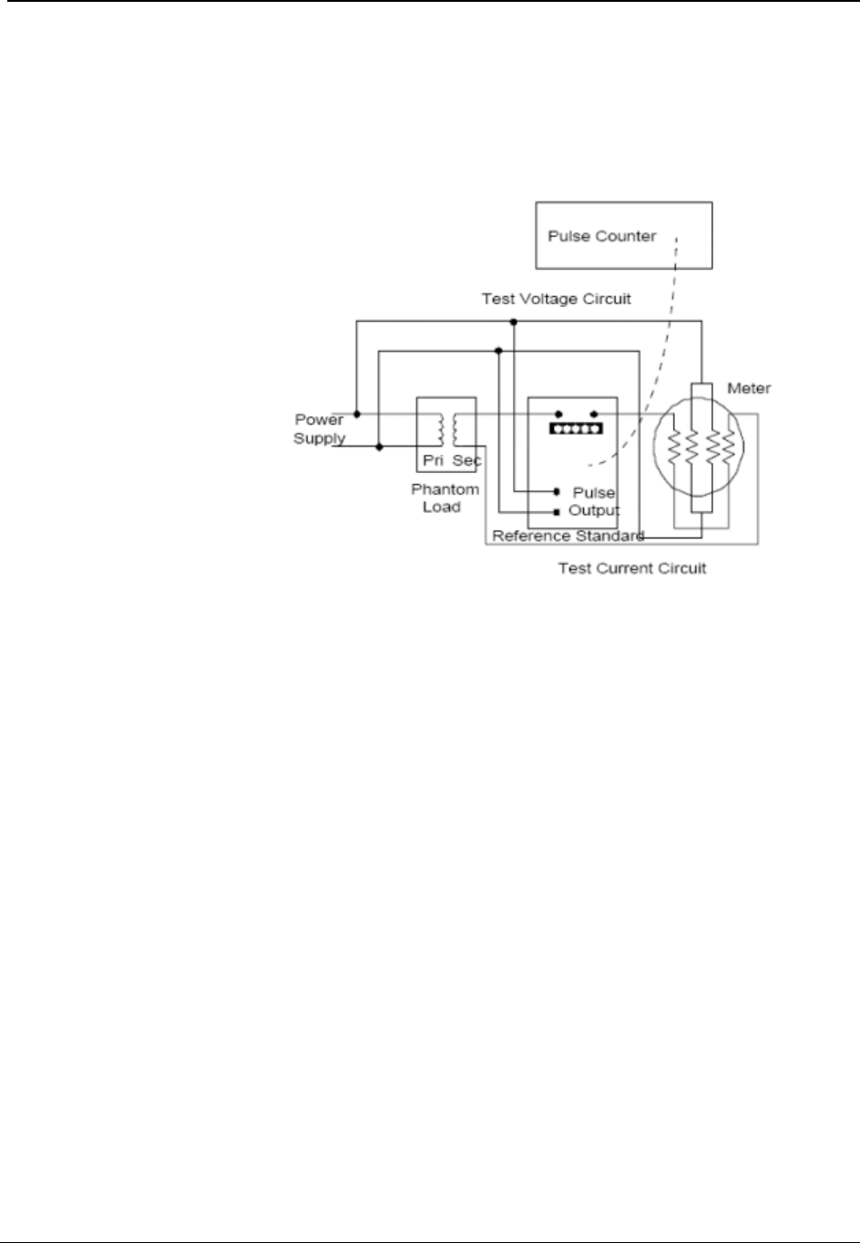
Operation: CVSO OpenWay Register
CENTRON® OpenWay™ Meter Technical Reference Guide 59
Demand Test Method
1 Connect the meter under test and the reference standard in the same circuit with all
voltage coils in parallel and current coils in series as per standard meter testing
procedures.
Figure 17: Test Connections
2 Apply rated voltage to the meter under test and the reference standard. Set the test
current to the desired level (FL, LL, or PF test amps or any desired level within the
meter rating). To ensure that the supply polarities are correct, check that the Load
Emulation Annunciator is traversing in the forward direction. Switch off only the
current to both the meter and the standard.
3 Reset and enable the pulse counting device.
4 Put the CENTRON OpenWay meter into Test Mode by pressing the Test switch. Once
this has been done, push in the Demand Reset switch to zero the test registers and start a
new demand interval.
5 Start the test by switching on the current to all meters and the reference simultaneously.
6 The End-of-Interval (EOI) flag will appear for five seconds in the display after the end
of the demand interval. At this time, switch off the current to all meters simultaneously
and stop the pulse count. Do not disconnect the voltage to the meter.
7 Record the pulse counter total and the values displayed on the CENTRON OpenWay
meter.
8 Perform calculations A, B, C, and D (if applicable) in the demand calculations section
and compare the results.
Draft

Operation: CVSO OpenWay Register
60 CENTRON® OpenWay™ Meter Technical Reference Guide
Meter Single Phase Test Constants (SPTC)
Form Series A Phase
Only B Phase
Only C Phase
Only
9 or 16 3Ø, 3W, 0.911 .866 .0866 1
9, 16, or 14 3Ø, 4W, wye 1 1 1 1
This test method is valid for kWh, kVAh, kvarh, kW, kVA, and kvar at any load or
power factor.
Demand Calculations
With solid-state metering, conducting energy and demand tests may be considered
redundant since they are both results of the same measurement.
Calculation A: Actual Active Energy (kWh)
Actual active energy is calculated using the following formula:
kWh = PT x Kh x N/1000
where: Kh = watt-hours per pulse output value from the reference
standard. (A watt and/or a VA standard must be used.)
PT = Total pulses accumulated from the reference standard
N = Coil factor (See Testing With the infrared Test LED)
Pre-calculate the total pulses expected with the following formula to ensure that the pulse
counter display does not overflow:
PT x Kh = V x I x T/(Kh x 60)
where: V = Voltage applied to standard
I = Current applied to standard
T = Test Mode demand interval length in minutes
If Test Mode display is in watt-hours (Wh), divide by 1000 to get kWh.
Calculation B: Actual Active Demand (kW)
Actual active demand is calculated using the following formula:
kW = kWh x 60/T
where: T = Test Mode demand interval length in minutes
Draft

Operation: CVSO OpenWay Register
CENTRON® OpenWay™ Meter Technical Reference Guide 61
Calculation C: Actual KVA Hours
kVAh = PT x Kh x N/ (1000*SPTC)
where: N = Coil factor (See Testing With the Infrared Test
LED)
SPTC = Single phase test constant (See the table in
Demand Test Method)
Calculation D: Actual kVA Demand
kVA = kVAh x 60/T
where: T = Test Mode demand interval length in minutes
Field Testing
Field testing of the CENTRON OpenWay meter may be accomplished with conventional
methods using either the infrared test pulses or the load emulation annunciator.
Required Hardware
The typical field test setup consists of a phantom load, a portable standard, and an infrared
test pulse adapter with counter or snap switch assembly.
Test Method Using Infrared Pulse Adapter
The pulse adapter runs the test for a programmed number of pulses. The number of pulses is
set on the test pulse adapter by the use of counter switches. The adapter will automatically
start the test when the START COUNT button is pressed.
When the test begins, the test pulse adapter counts the pulses it receives from the meter until
the programmed number of pulses have been received.
When this occurs, the pulse adapter automatically shuts off the portable standard. The
standard then displays the number of equivalent disk revolutions which is then compared to
the number of pulses for the test.
Test Method Using a Snap Switch Assembly
This method is similar to the above except starting and stopping of the standard is
performed manually.
To conduct the test, the technician observes the position of the load emulation annunciator
and simultaneously starts the standard through the snap switch. After observing a
predetermined number of emulated disk rotations, the technician stops the standard with the
snap switch. A comparison is then made between the predetermined number of emulated
disk rotations and equivalent disk rotations indicated on the watthour standard.
Draft

Operation: CVSO OpenWay Register
62 CENTRON® OpenWay™ Meter Technical Reference Guide
Troubleshooting
Typically, meters are placed in a very unfriendly environment. While the CENTRON
OpenWay meter is designed to perform within this harsh environment, things can go wrong
with the meter or installation.
Fatal Errors
Fatal errors cause the display to lock on the error code because of the possibility that billing
data may have been corrupted or that the meter may not be operating correctly. If multiple
fatal errors occur, the one with the lowest number will be the error code that locks on the
display.
The CENTRON OpenWay meter will check for fatal errors:
when a meter reconfigure is performed.
when power is initially energized and upon future power restoration.
while performing key operations.
The different fatal errors should be handled as described in the table below. Fatal errors can
only be cleared by performing a Factory Reset on the meter. A Factory Reset will wipe out
all information in the meter, so be sure to try to retrieve any meaningful data from the meter
prior to performing the Factory Reset. After this is performed, the meter must be
reprogrammed.
Sometimes when a battery is plugged into a meter while the meter is powered down,
it will result in a fatal error when the meter is powered up. This is due to an unstable
voltage on the battery. In this case, the fatal error can be ignored and a Factory Reset
performed on the meter. To prevent these fatal errors from occurring, always power
up the meter before plugging a battery into it.
Fatal Errors
Error Code
Error Possible Cause Error Description
FAtError1 MCU
FLASH
Error
The meter has
detected a problem
with the program
memory.
If this error occurs, Factory
Reset the meter, reprogram the
meter and check for proper
operation. If the error continues
to exist, return the meter for
repair.
FAtError2 RAM
Error The meter has
detected a problem
with the RAM.
If the meter detects this
problem, return the meter for
repair.
FAtError3 DATA
FLASH
Error
The meter has
detected a problem
with the data flash
(non-volatile
memory).
If this error occurs, Factory
Reset the meter, reprogram the
meter and check for proper
operation. If the error continues
to exist, return the meter for
repair.
Draft

Operation: CVSO OpenWay Register
CENTRON® OpenWay™ Meter Technical Reference Guide 63
Fatal Errors
Error Code
Error Possible Cause Error Description
FAtError4 Front
End
Processo
r Error
A problem has
occurred with the
metrology portion of
the meter.
If the meter detects this
problem, return the meter for
repair.
FAtError5 Power
Down
Error
A problem has
occurred while saving
billing data at time of
a power outage.
The billing data has been
corrupted. Factory Reset the
meter, reprogram the meter and
check for proper operation,
including several power cycles.
If the error continues to exist,
return the meter for repair.
FAtError6 File
System
Error
The meter has
detected a problem
with the file system
If the meter detects this
problem, return the meter for
repair.
FAtError7 Operatin
g System
Error
The meter has
detected a problem
with the operating
system
If the meter detects this
problem, return the meter for
repair.
Non-Fatal Errors
Non-fatal errors can be programmed to scroll during the one second display off-time or lock
on the meter display. If multiple non-fatal errors occur, the meter will display a combined
error message. For example, if a Low Battery error and a Loss of Phase error exist, the error
display will read Err 12----. In this case, if one of the errors had been programmed to
lock, and the other error had been programmed to scroll, the display will lock on the
combined error message.
Selecting a display mode by holding the magnet near the cover’s magnet icon at the 9
o’clock position allows that display mode sequence to scroll one time during a locked non-
fatal error. At the end of the display sequence, the error message locks onto the display
again.
Draft

Operation: CVSO OpenWay Register
64 CENTRON® OpenWay™ Meter Technical Reference Guide
Non-Fatal Errors
Error Code Error Possible Cause(s) Error Description
Err 1----- Low
Battery
Error
Battery Voltage
Low
Battery Not
Connected
Properly
A low battery check is
performed once a day and
upon a set clock procedure. A
low battery continues to
function; however, its reliability
decreases over time. As long
as the meter is not powered
down with a dead or missing
battery, the meter will continue
to function as normal.
If the meter is powered down
with a dead or missing battery,
then, when power is restored,
the meter’s clock will be off by
the duration of the outage, and
Load Profile and TOU will be
halted.
Err -2---- Loss of
Phase
Error
The voltage on
one of the phases
dropped below 45
volts.
The voltage on each phase is
checked every five seconds. A
phase must fail twice in a row
to cause an error. A Demand
Reset will clear this error.
Err --3--- Time-of-
Use
(TOU)
Error
• Current Season is
not programmed.
• Current Year is not
programmed.
• TOU halted due to
power down with
dead or missing
battery.
This is tested at power-up, at
midnight crossings, at season
changes, upon reconfigures
and upon set clocks.
Depending on the cause of the
error, it can be cleared with a
corrective reconfigure or with a
set clock with a good battery
present.
Err ---4-- Reverse
Power
Flow
Error
The configured
reverse power
threshold has
been reached
Reverse power is tested every
second and an accumulator for
it is maintained. If power is
delivered during the second,
then the accumulator is
cleared. If power is received
during the second, then the
accumulator is incremented. If
the accumulator reaches the
configured reverse power
threshold, then the error is
triggered.
A Demand Reset will clear this
error.
Draft

Operation: CVSO OpenWay Register
CENTRON® OpenWay™ Meter Technical Reference Guide 65
Non-Fatal Errors
Error Code Error Possible Cause(s) Error Description
Err ----5- Clock/
Load
Profile
Error
Load Profile
halted due to
power down with
dead or missing
battery.
This is tested upon power-up.
A set clock with a good battery
present will clear this error. Be
sure to read the Load Profile
data prior to setting the clock
to clear the error. The dead
battery will cause some invalid
intervals at the end of the data.
When the error is cleared,
Load Profile will be restarted
from the beginning to purge
the bad data.
Err -----6 Full
Scale
Overflow
Error
The calculated W
delivered demand
at an EOI
exceeded the
configured full
scale value.
This is tested at a demand
EOI. The maximum demand
register continues to
accumulate and W delivered is
still correctly displayed. When
a demand reset is performed,
the correct maximum W
delivered will be added to the
cumulative register.
A Demand Reset will clear this
error.
If a full scale overflow occurs,
check the installation to ensure
that the current capacity of the
meter has not been exceeded.
A full scale overflow error in no
way affects the existing billing
data.
Err - 9--- SiteScan
Error SiteScan auto
service detection
could not
determine the
meter’s service
type.
This is tested after the power-
up delay time has expired
following a power-up, an exit
Test mode and a reconfigure
of SiteScan configuration data.
While this condition is present,
SiteScan Diagnostics and
Voltage Quality are disabled.
Once a SiteScan error occurs,
SiteScan will continue to test
for it every 5 seconds until the
service is determined. When
the service is determined, the
error condition is cleared.
Draft

Operation: CVSO OpenWay Register
66 CENTRON® OpenWay™ Meter Technical Reference Guide
Other Problems
Demand Reset Cannot Be Initiated Through PC or Handheld
Insufficient security.
Communication cannot be established. See Programmer Cannot Communicate with
Meter.
Incorrect or No Accumulation of kWh or kW
Demand Delay Selected—kW will not accumulate immediately after a power outage if
Cold Load Pickup (demand delay) has been selected. Accumulation will begin
immediately after demand delay has expired. Verify meter program and reconfigure
meter.
Component Failure—Return the meter for repair.
Meter is not being tested properly—See Recommended Testing Procedures.
Reset Mechanism Does Not Initiate Demand Reset
Reset Has Occurred Within Last Programmable Time Period, e.g., 60 Seconds—
Manual demand reset cannot occur within 60 seconds of the previous demand reset.
Wait 60 seconds before trying again.
Reset Switch Disabled—Reset switch may be disabled through software.
Register Board not Properly Installed in Upper Housing—Verify that the Register
board is fully engaged with the upper inner cover.
Blank Display
Power Not Applied to Meter—Apply voltage to A phase (or phase-to-phase voltage
with a polyphase power supply).
Voltage Too Low for Meter Startup—the CENTRON OpenWay meter requires at least
45 volts to start up.
Voltage Connector Loose—Voltage connector of the meter loose from the Register
board; re-secure the connector.
Component Failure—Return the meter for repair.
Board-to-Board Connector Not Seated—Verify proper connection of board-to-board
connector.
Time and Date Wrong (TOU Version)
Time/Date Wrong in PC or Handheld Device—Verify and update time/date in
programming device and download new time and date to meter. Refer to the appropriate
software manual for more detailed directions.
Wrong Line Frequency—Verify proper line frequency is selected in setup routine in
programming software. Select proper frequency and reconfigure meter.
Battery Failure During Power Outage—Verify battery voltage. Replace battery and
download new time and date.
Daylight Savings Time Not Programmed Correctly—Verify DST is selected in
program. Reconfigure meter with correct program.
Component Failure—Return meter for repair.
Draft

Operation: CVSO OpenWay Register
CENTRON® OpenWay™ Meter Technical Reference Guide 67
Programmer Cannot Communicate with Meter
Optical Probe Cable Assembly Failure—Check cable with known meter that
communicates. Check meter against known cable that is functioning. Also check
batteries in cable assembly (if applicable).
COM Port in Programmer Is Set Wrong—Verify proper COM port number has been
selected in the setup routine of the programming software. If the wrong COM port is
selected communications will not occur.
Security Code in Meter—If security codes have been downloaded to the meter, the
programming device must have the proper code to make connection to the meter. Verify
security codes in the setup routine of the programming software.
Cable Not Connected Properly—Verify optical probe lines up properly over the optical
connector. Re-install cover for proper alignment. Verify PC (or handheld) and cable are
securely connected and attached to the correct COM port.
Incorrect Cable Selection—Wrong cable selected in Options | Optical Probes section of
PC-PRO+ Advanced.
Main Register Electronics Failure—Return meter for repair.
Magnetic Switch Does Not Activate the Alternate or Toolbox Mode
Magnetic Field Is Too Weak—Place magnet closer to switch or use stronger magnet.
Magnet was not in place for four consecutive seconds.
Magnetic Switch Failure—Return meter for repair.
Test Mode Switch Does Not Place Meter in Test Mode
No display items in Test Mode Display List.
Switch deactivated by software—Activate switch in software and reprogram meter.
Register Board not Properly Installed in Upper Housing—Verify that the Register
board is fully engaged with the inner cover.
Switch or Electronic Failure—Return meter for repair.
Diagnostic 1 Condition Incorrectly Active
Verify that meter determined the correct service type.
Diagnostic 2, 3, or 4 Condition Incorrectly Active
Verify that thresholds are not set too tight.
Counters Are Too High
Verify that thresholds are not set too tight.
Draft

Operation: CVSO OpenWay Register
68 CENTRON® OpenWay™ Meter Technical Reference Guide
Maintenance
Preventive Maintenance
No scheduled or preventive maintenance is necessary for the CENTRON OpenWay meter.
Line potential may exist on the battery terminals. Follow these
precautions:
• Never short-circuit batteries (such as by measuring current
capability with an ammeter).
• Do not recharge batteries.
• Do not store or transport batteries in metal or other
electrically conductive containers.
• Keep batteries separated. If stored in a container where
they can contact each other, face them in the same
direction to prevent short circuits.
• Do not operate batteries at temperatures above 85°C
(185°F).
• Dispose of batteries where they will not be punctured,
crushed, or incinerated.
• Discard the battery using proper hazardous waste
procedures.
Corrective Maintenance
Because of the high level of integrated packaging and surface-mount components, on-board
component repairs are not recommended. The entire meter should be returned to Itron, Inc.
Customer Service for repair.
Draft
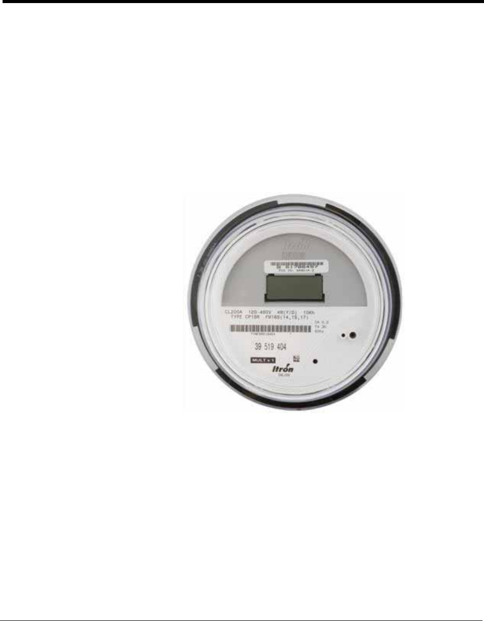
CENTRON® OpenWay™ Meter Technical Reference Guide 69
In This Chapter
Physical Description ............................................................................................70
FCC Regulations..................................................................................................70
Tamper Detection ................................................................................................70
Retrofitting the CP1SR Personality Module........................................................72
Testing, Troubleshooting and Maintenance.........................................................72
The CP1SR module is a one-way, unlicensed radio frequency (RF) personality module that
attaches to the CENTRON OpenWay meter base (See the figure below). It offers a cost-
effective solution for the endpoints in automatic and off-site meter reading applications.
Figure 18: CENTRON CP1SR Meter
CHAPTER 5
Operation: CP1SR Version
Draft

Operation: CP1SR Version
70 CENTRON® OpenWay™ Meter Technical Reference Guide
Physical Description
The CP1SR personality module is constructed of a flame retardant printed circuit board
material which supports the discrete, surface-mounted, and integrated circuit components. A
microstrip etched on the circuit board serves as the RF antenna. The CP1SR personality
module easily snaps into the meter module mounting bracket. This module is then
electronically attached to the metrology board via a board to board connector. The following
information is sent to the personality module from the base metrology board:
Line voltages
Energy data
Basic status information
The CP1SR contains contacts on the module board, located at the 12 o’clock position behind
the LCD, for resetting the energy register and tamper counters. This can be accomplished
with the ZRO-C2A Resetter.
The CP1SR uses a unique module (ERT) identification number, provided by Itron. This ID
number is contained in each message transmission and is used by the handheld and billing
system to determine meter identity and location. This ID number, which is contained on a
bar-coded label, is placed on the LCD housing directly above the LCD display.
FCC Regulations
The CP1SR communicates in the unlicensed, 910-920 MHz band governed by the US Code
of Federal Regulations (CFR) Title 47, Part 15 Radio Frequency Devices, Sub Part C
Paragraph 247 Intentional Radiator.
Changes or modifications not expressly approved by Itron could void
the users authority to operate the equipment.
Tamper Detection
The CENTRON Polyphase CP1SR features the Itron patented method of tamper detection
that senses both meter removal and meter inversion. The removal tamper (RTPR)
increments a counter each time the meter is abruptly removed from a live meter socket. The
tamper counter utilizes a tilt switch to detect when the meter is removed from a meter
socket.
Testing the CENTRON Polyphase CP1SR Tamper Counter
SCM Testing
In order to test the power removal counter, the meter must sense a shaken condition
associated with a power outage.
Draft

Operation: CP1SR Version
CENTRON® OpenWay™ Meter Technical Reference Guide 71
1 Place the meter in a socket.
2 Apply power to the meter.
3 Remove the meter from the live socket.
4 Replace the meter in the socket.
The meter has incremented the removal tamper counter.
The CP1SR uses the power outage (the meter being removed from a live socket) in
conjunction with the meter being shaken simultaneously to increment the power removal
counter.
The inversion counter increments when the meter senses reverse current flow. The
metrology board senses reverse power flow and sends this status to the CP1SR personality
module. The CP1SR then increments the counter and transmits the count.
As part of the 96-bit Standard Consumption Message, 4 bits are allocated for tamper
indications, which include the power removal and meter inversion counters. The table below
shows the removal and inversion information based on the reported tamper count.
Tamper Count:
Binary Tamper Count Inversion Removal
0000 0 0 0
0001 1 1 0
0010 2 2 0
0011 3 3 0
0100 4 0 1
0101 5 1 1
0110 6 2 1
0111 7 3 1
1000 8 0 2
1001 9 1 2
1010 10 2 2
1011 11 3 2
1100 12 0 3
1101 13 1 3
1110 14 2 3
1111 15 3 3
Draft
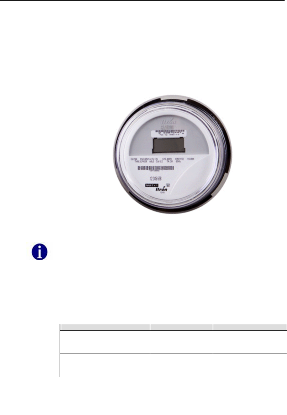
Operation: CP1SR Version
72 CENTRON® OpenWay™ Meter Technical Reference Guide
Retrofitting the CP1SR Personality Module
The CENTRON R300 is a one-way radio frequency personality module that transmits
within the unlicensed 910-920 MHz frequency band governed by the US Code of Federal
Regulations (CFR) Title 47, Part 15 Radio Frequency Devices, Sub Part C Paragraph 247
Intentional Radiator. Any device operating within this unlicensed frequency band must
contain an FCC Identification number. The retrofit kit includes a CP1SR register with a
FCC ID label as shown below.
Figure 19: CENTRON Polyphase CP1SR Meter
Changes or modifications not expressly approved by Itron could void the user’s
authority to operate the equipment.
To retrofit an existing meter with an R300 module, see Retrofitting with Personality
Modules.
Testing, Troubleshooting and Maintenance
Diagnostic Display OFF Period Notes
Metrology message stopped for
greater than 15 seconds and
less than 10 minutes
Error Missing message with
diagnostic flag also
written to the memory
Power up with Phase A, B, and
C voltage equal to 0 degrees noSEr Meter installed in an
invalid service
configuration.
Draft
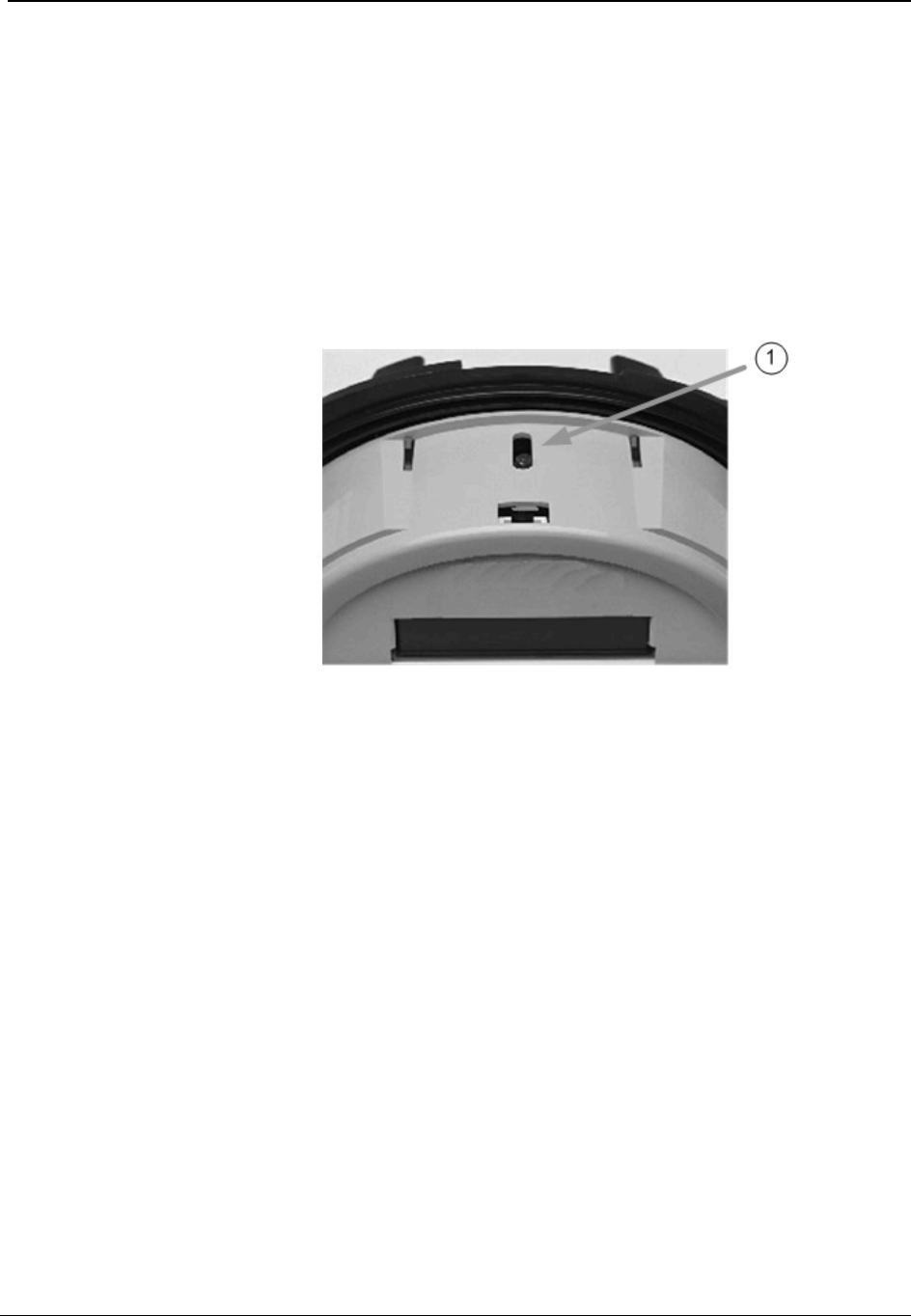
Operation: CP1SR Version
CENTRON® OpenWay™ Meter Technical Reference Guide 73
Testing Support Features
Infrared Test LED
The CENTRON Polyphase CP1SR meter is equipped with an Infrared Test Light Emitting
Diode (LED) (M in the figure below) where each pulse represents a fixed value of watthour
measurement. The LED is located on the top of the meter as the meter is viewed from a
typical installation. The pulse weight represented by the LED pulses is 1.0 watthour per
pulse (Kh=1.0) for a Form 9S meter and 10.0 watthour per pulse (Kh=10.0) for a Form 16S
meter.
Figure 20: Test LED Location
Pulse Detector
An optional pulse detector is available for the CENTRON OpenWay meter. The pulse
detector has an infrared pickup with two visible LEDs. When positioned over the
CENTRON Polyphase light pipe, it will produce a visible flash when an infrared pulse is
received from the metrology. The right LED will flash once for each infrared Wh pulse
while the left LED will flash once for every 10 infrared pulses received. The left LED on the
pulse detector is helpful when heavier loads are present on the system being examined. This
can be used to verify that the metrology is measuring energy when installed and to conduct
timing tests to determine the amount of load on meter.
Draft
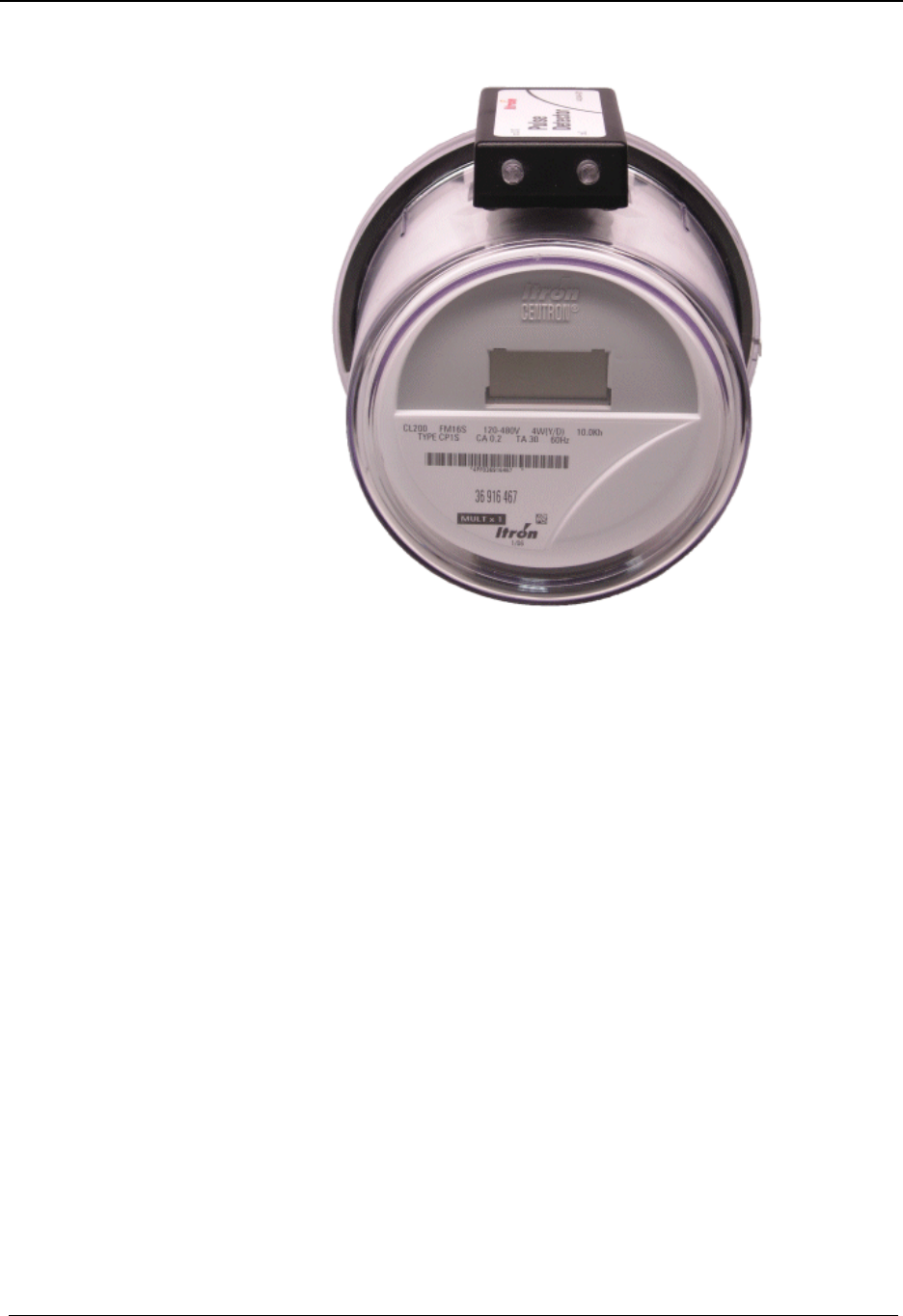
Operation: CP1SR Version
74 CENTRON® OpenWay™ Meter Technical Reference Guide
Figure 21: Pulse Detector
Annunciators
Watthour Annunciators
The CP1SR meters are equipped with three annunciators which show the direction of energy
flow. The squares will scroll left to right for positive (line to load) energy flow, and right to
left for negative energy flow. Each change in state of the watt disk emulator is equivalent to
1 x Kh.
Draft

CENTRON® OpenWay™ Meter Technical Reference Guide 75
A
annunciator
A Liquid Crystal Display (LCD) label that is
displayed to identify a particular quantity being
displayed
B
baud
Unit of data transmission signaling speed, roughly
analogous to bits per second (bps)
D
display duration
The programmed number of seconds that a quantity is
displayed on the LCD before it is replaced with the
next quantity in the display sequence
E
EEPROM
Electrically Erasable Programmable Read Only
Memory. A memory chip that can only be erased by
an electrical signal (retains data during a power
outage)
electronic detent
An algorithm in firmware which restricts the device
to metering energy flow only to the customer
(unidirectional metering)
EPROM
Erasable Programmable Read Only Memory. Similar
to EEPROM except it requires ultraviolet light to be
erased
F
firmware
Computer programs stored in non-volatile memory
chips (ROMs, PROMs, EPROMs, EEPROMs, etc.)
fixed decimal
A display format that always retains the same number
of digits to the right of the decimal point
floating decimal
A display format that allows a maximum number of
digits to the right of the decimal, but can display any
number of digits to the right of the decimal equal to
or less than that number specified
I
IDM
Interval Data Message
L
LCD
Liquid Crystal Display
LED
Light-Emitting Diode
M
magnetic switch
A mechanical switch consisting of a thin metal
contact which is closed by an external magnetic field
N
nonvolatile memory
See EEPROM
R
RS-232
A communication media whereby information is
transmitted through a serial bit stream
Glossary of Terms
Draft

Glossary of Terms
76 CENTRON® OpenWay™ Meter Technical Reference Guide
S
SCM
Standard Consumption Message
Draft

CENTRON® OpenWay™ Meter Technical Reference Guide 77
A
annunciator • 75
antenna
RF • 70
B
base metrology • 15
baud • 75
button
test mode • 13
C
circuit board
metrology • 70
counter
power removal • 70
cover • 12
Crystal Time synchronization • 13
current/potential terminals • 13
E
EEPROM • 75
electronic detent • 75
EPROM • 75
F
firmware • 75
fixed decimal • 75
floating decimal • 75
I
inversion counter • 70
inversion tamper (ITPR) • 70
ITPR • 70
L
LCD • 75
LCD display • 13
LCD housing • 70
LED • 75
line frequency • 13
lithium battery
shelf life • 11
M
magnetic switch • 75
meter base • 12, 13, 69
meter cover • 12
meter inversion • 70
meter removal • 70
meter storage • 11
metrology board • 70
module
R300 • 69
N
nonvolatile memory • 75
non-volatile memory • 69
O
operating temperature range • 13
optical connector • 12
P
PC-PRO+ Advanced Programming Software • 1
personality module
C1SR • 69, 70
handling • 12
power removal counter • 70
PRO-READ • 1
R
R300 module • 69
ReadOne Pro handheld reader • 70
removal tamper (RTPR) • 70
removal tamper counter • 70
reset mechanism • 12
Retrofit Kit
C1SR • 72
reverse current flow • 70
reverse power flow • 70
RF antenna • 70
RS-232 • 75
RTPR • 70
S
segment test • 13
storage
meter • 11
T
tamper indication • 70
test mode annunciator • 13
test mode button • 13
Index
Draft

Index
78 CENTRON® OpenWay™ Meter Technical Reference Guide
Z
ZRO-C2 Resetter • 70
Draft