Itron AMI-2 CENTRON OPENWAY ELECTRICITY METER User Manual USERS MANUAL
Itron Electricity Metering, Inc. CENTRON OPENWAY ELECTRICITY METER USERS MANUAL
UserManual.wiki
>
Itron
>
AMI 2 User Manual
USERS MANUAL
Navigation menu
Upload a User Manual
Namespaces
Wiki Guide
HTML
PDF
Info
Views
User Manual
Discussion / Help
Navigation


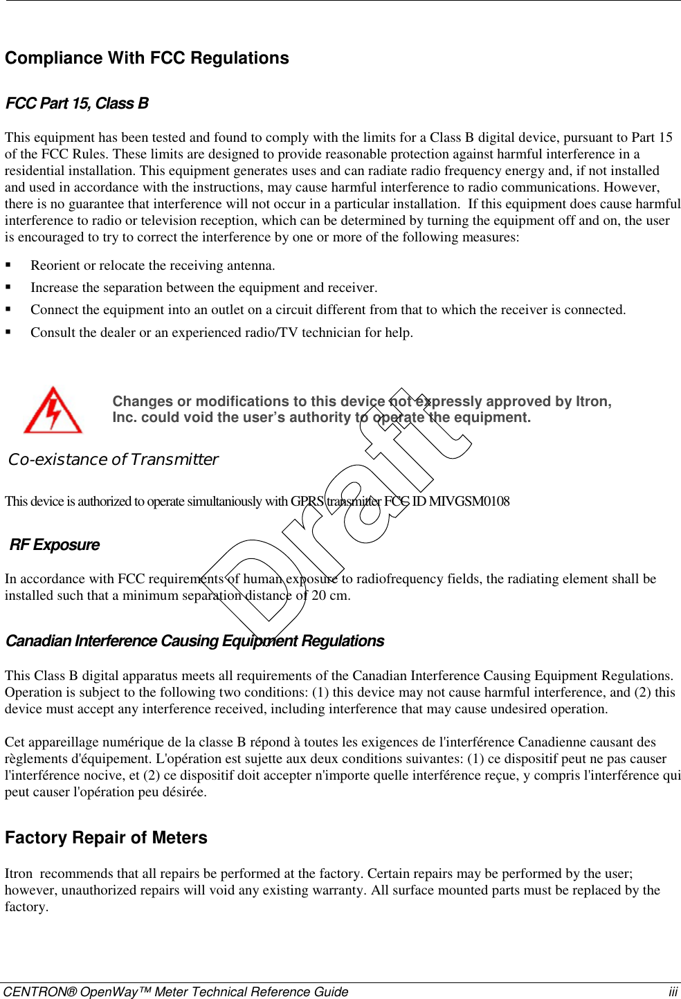

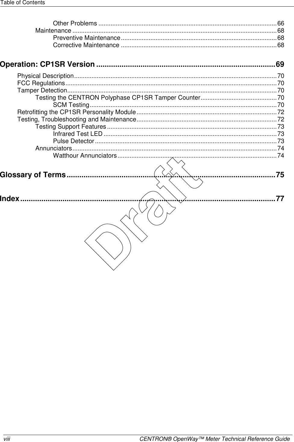

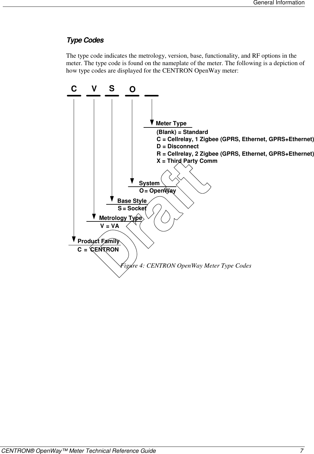


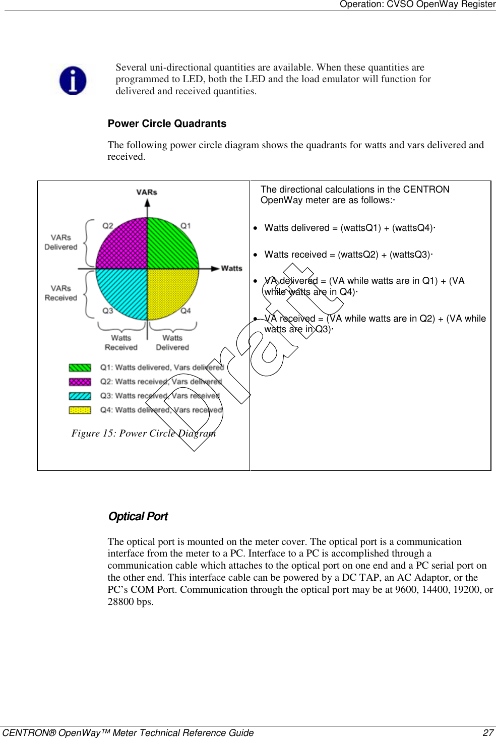
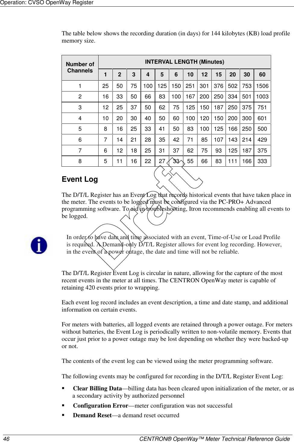
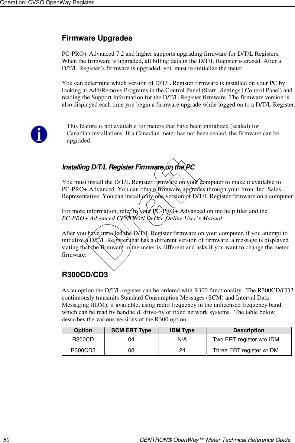
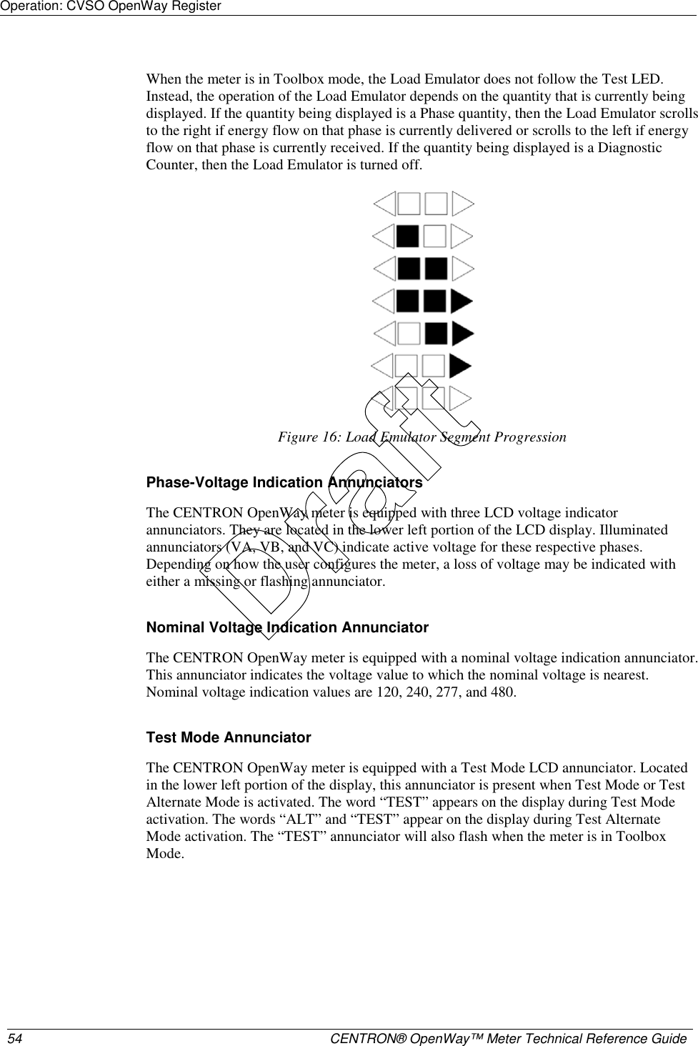
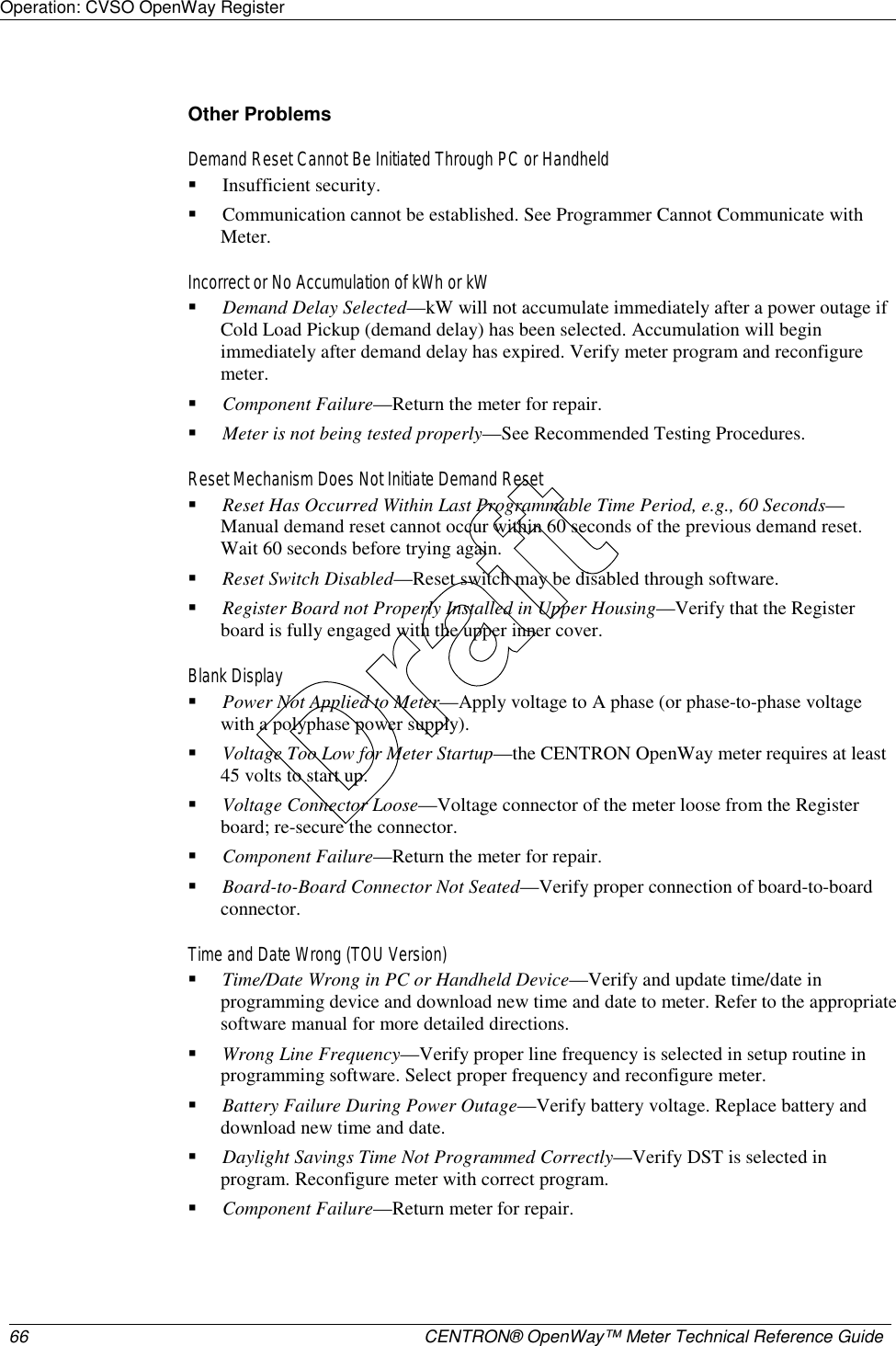
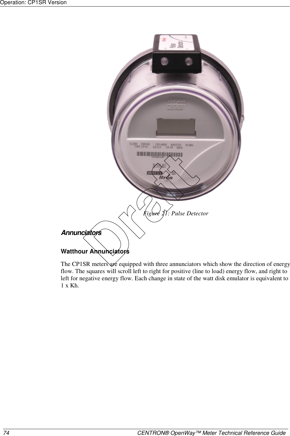
![Operation: CVSO OpenWay Register CENTRON® OpenWay™ Meter Technical Reference Guide 31 All of the display items in the next two tables may be selected by TOU Rate. They also may be selected from the four Self Read buffers, the two Demand Reset Snapshot buffers, and Last Season Self Read buffer. Energy Data Display Items Display Mode Energy Data Display Item Normal Alternate Test Toolbox 1 Wh (delivered, received, net, uni-directional) X X X Varh (delivered [lag], received [lead], Net, net delivered, net received, Q1, Q4) X X X VAh (delivered, received; arithmetic & vectorial) X X X VAh lag (vectorial) X X X Qh (delivered, received) X X X Vh (Phase A, Phase B, Phase C, Average) X X Ah (Phase A, Phase B, Phase C) X X V2h Aggregate X X A2h Aggregate X X Demand Data Display Items Display Mode Demand Data Display Item Normal Alternate Test Toolbox2 W Delivered (Max, Present, Previous, Projected, Cumulative, Continuous Cumulative) X X X W Received (Max, Present, Previous, Projected, Cumulative, Continuous Cumulative) X X X W Net (Max, Present, Previous, Projected, Cumulative, Continuous Cumulative) X X X W Uni-directional (Max, Present, Previous, Projected, Cumulative, Continuous Cumulative) Var Q1, Var Q4 (Max, Present, Previous, Projected, Cumulative, Continuous Cumulative) X X X Var Delivered [lag: Q1+Q2] (Max, Present, Previous, Projected, Cumulative, Continuous Cumulative) X X X Var Received [lead: Q3+Q4] (Max, Present, Previous, Projected, Cumulative, Continuous Cumulative) X X X Draft](https://usermanual.wiki/Itron/AMI-2/User-Guide-715419-Page-42.png)
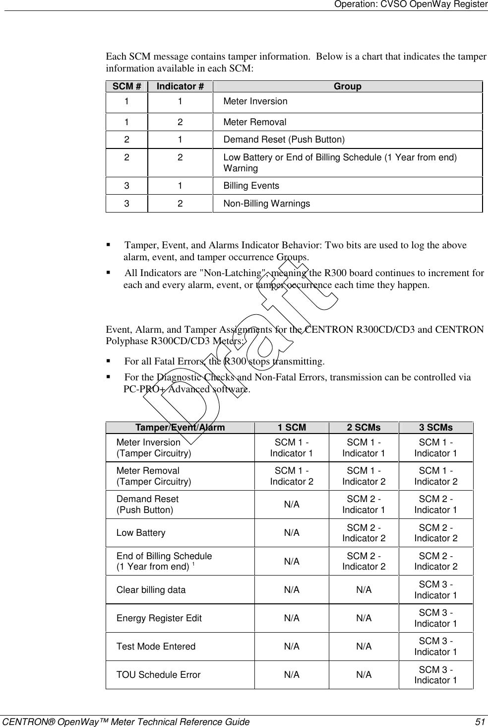
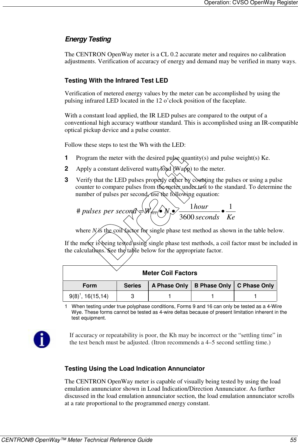
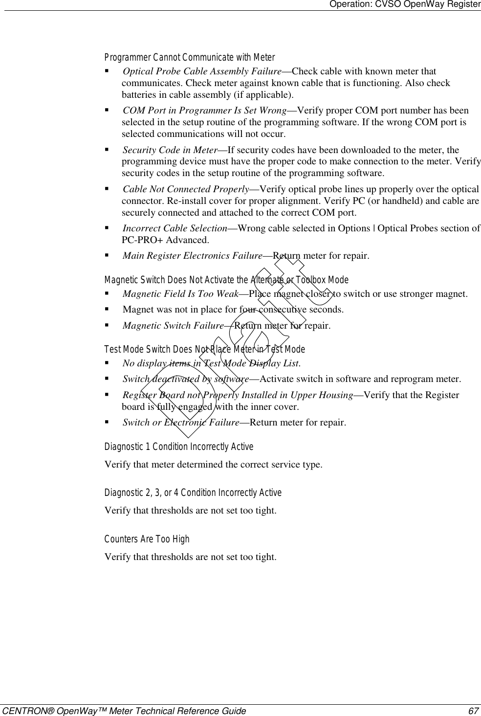
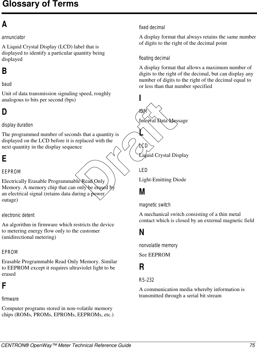
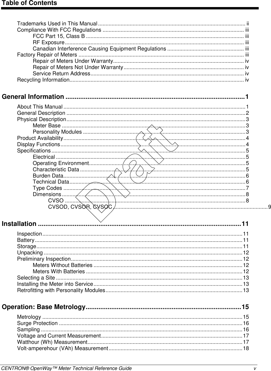
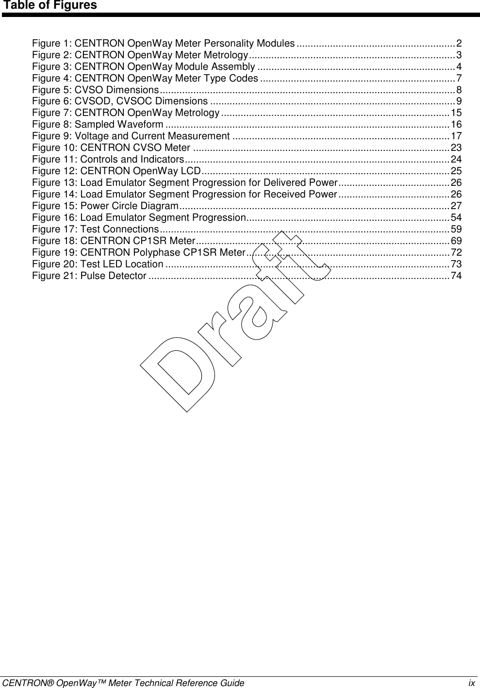
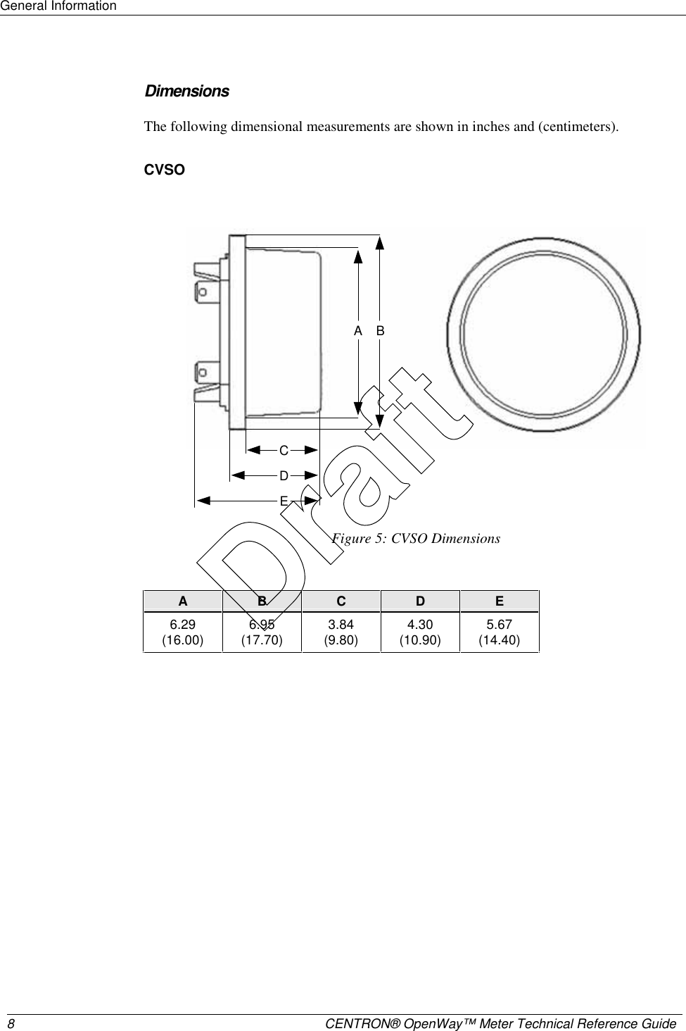
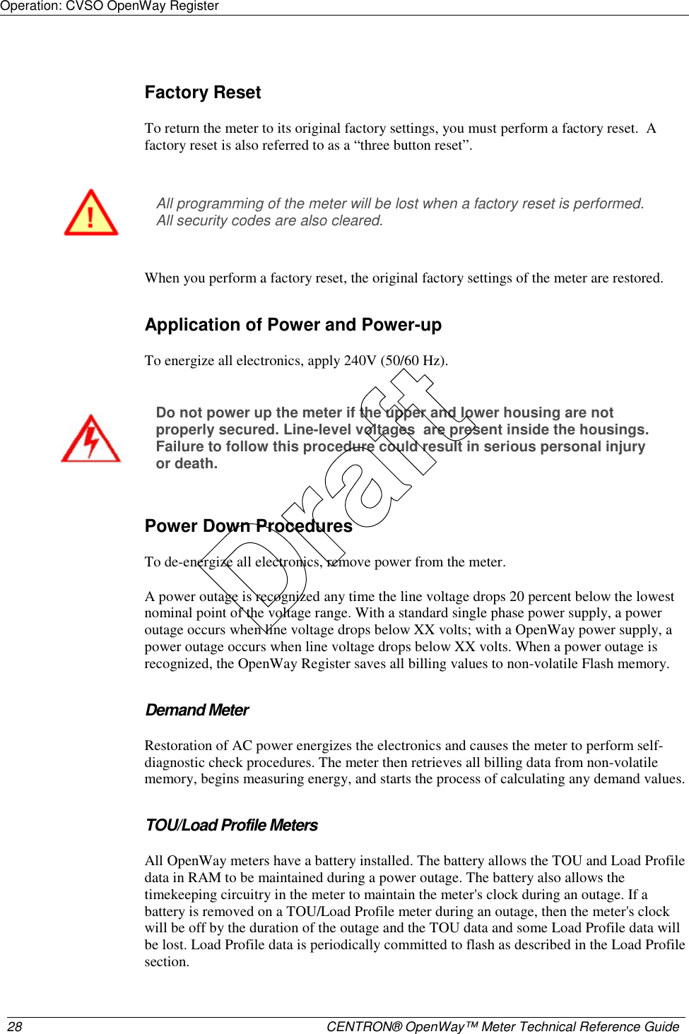
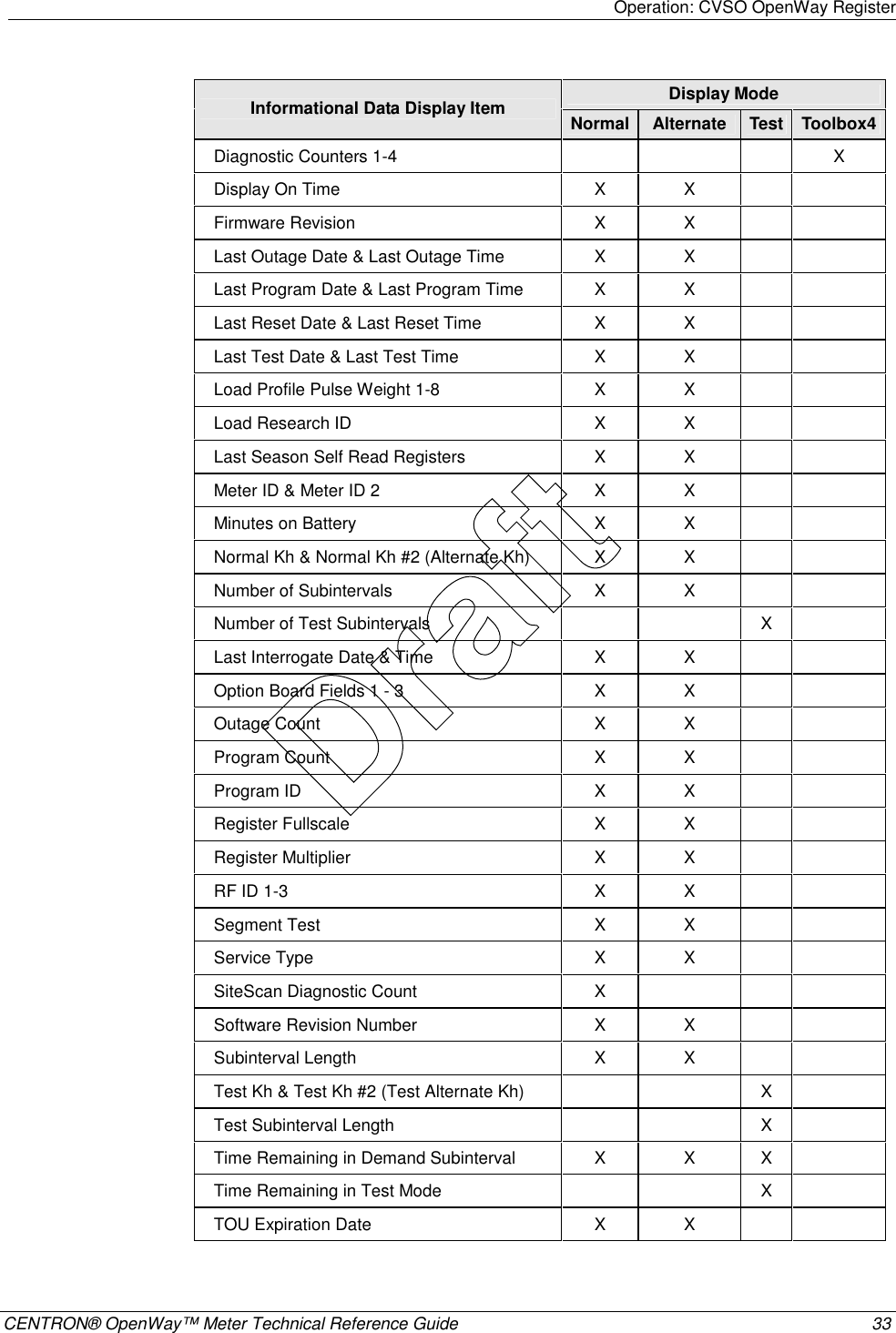
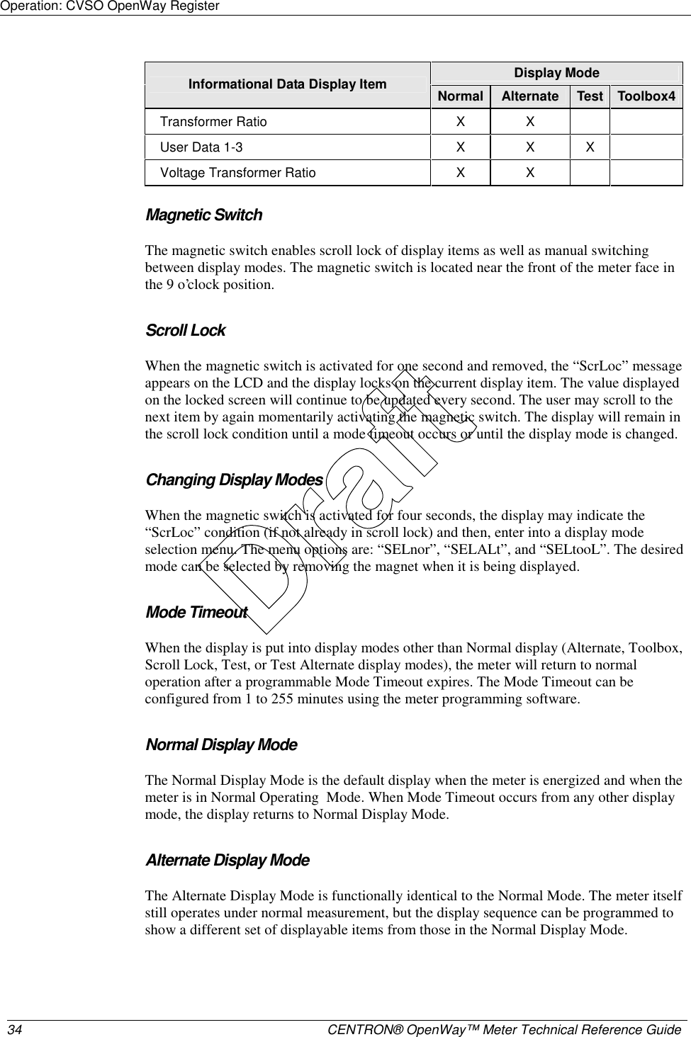
![Operation: CVSO OpenWay Register 32 CENTRON® OpenWay™ Meter Technical Reference Guide Display Mode Demand Data Display Item Normal Alternate Test Toolbox2 Var Net VA Delivered [arithmetic or vectorial] (Max, Present, Previous, Projected, Cumulative, Continuous Cumulative) X X X VA Received [arithmetic or vectorial] (Max, Present, Previous, Projected, Cumulative, Continuous Cumulative) X X X VA Lag (Max, Present, Previous, Projected, Cumulative, Continuous Cumulative) X X X Max A (per phase: A, B, C) X X PF Average X X Min P.F. X X Coincident Demands (up to 4) X X Instantaneous Data Display Items Display Mode Instantaneous Data Display Item Normal Alternate Test Toolbox3 Instantaneous W X X X Instantaneous Var X X X Instantaneous VA (arithmetic & vectorial) X X X Instantaneous Volts (A, B, C) X X X Instantaneous Amps (A, B, & C) X X X Instantaneous P.F. X X Instantaneous Frequency (Hz) X X Instantaneous Current Phase Angles (A, B, C) X Instantaneous Voltage Phase Angles (A, B, C) X Informational Data Display Items Display Mode Informational Data Display Item Normal Alternate Test Toolbox4 Calibration Date & Calibration Time X X Cold Load Pickup Outage Time X X Current Transformer Ratio X X Current Date, Day & Current Time X X Days Since Demand Reset X X Demand Reset Count X X Draft](https://usermanual.wiki/Itron/AMI-2/User-Guide-715419-Page-43.png)
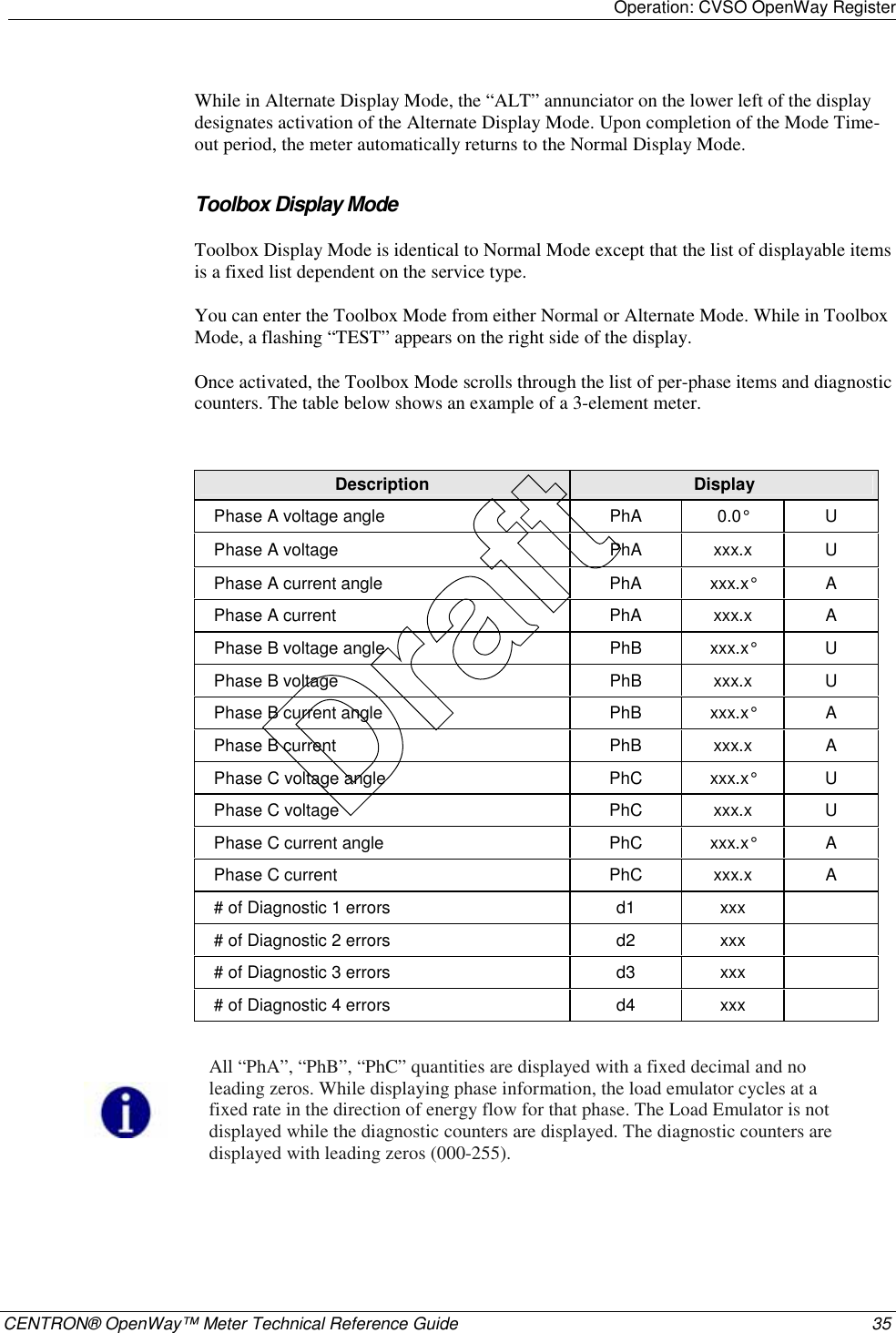
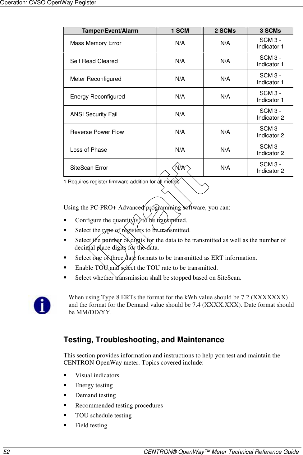
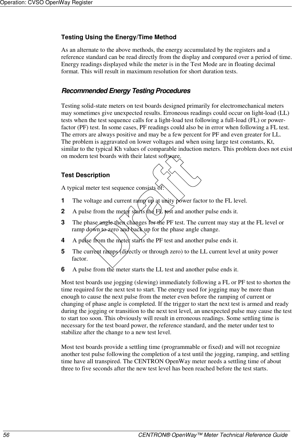
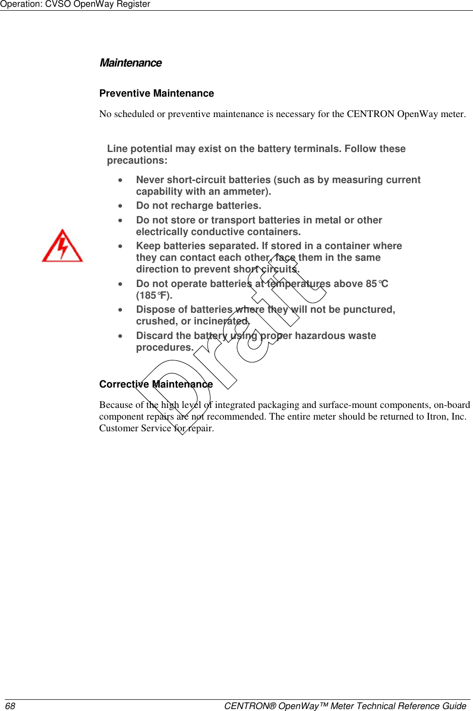
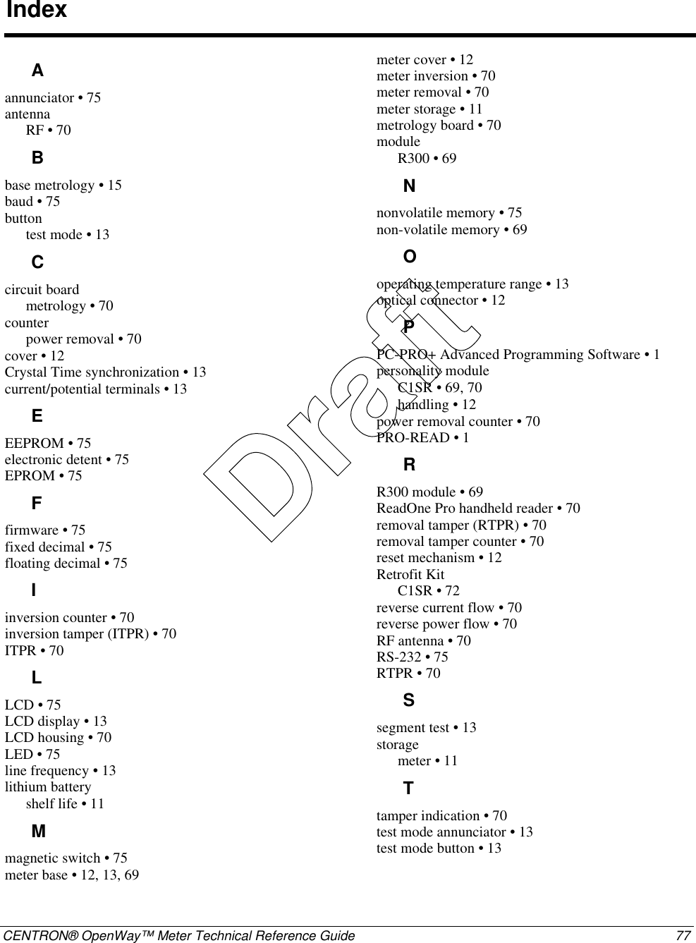
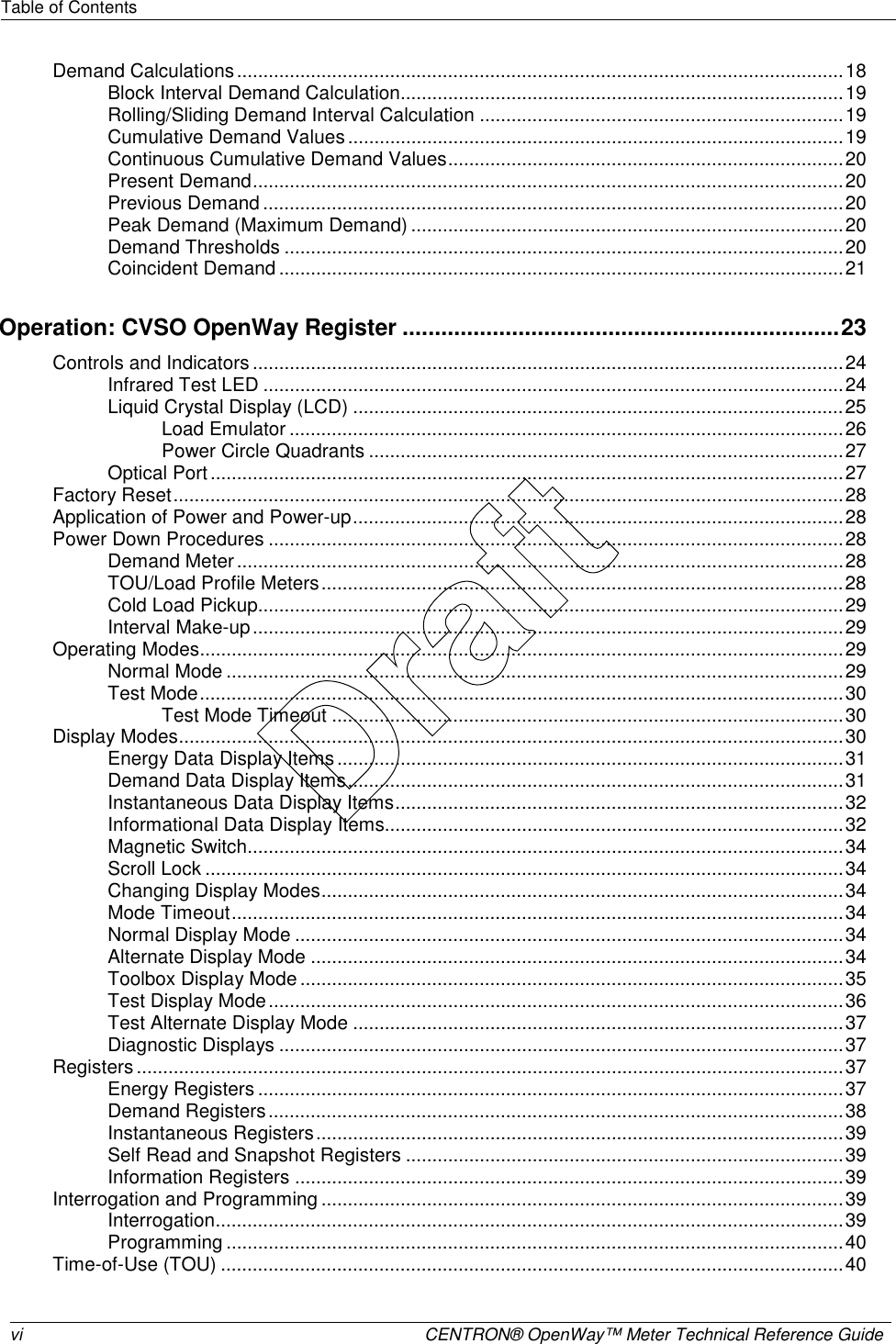
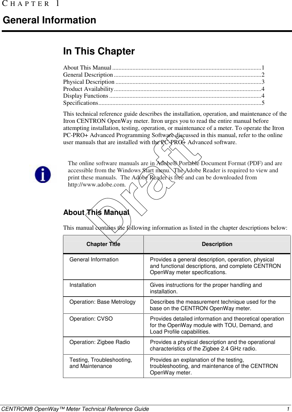
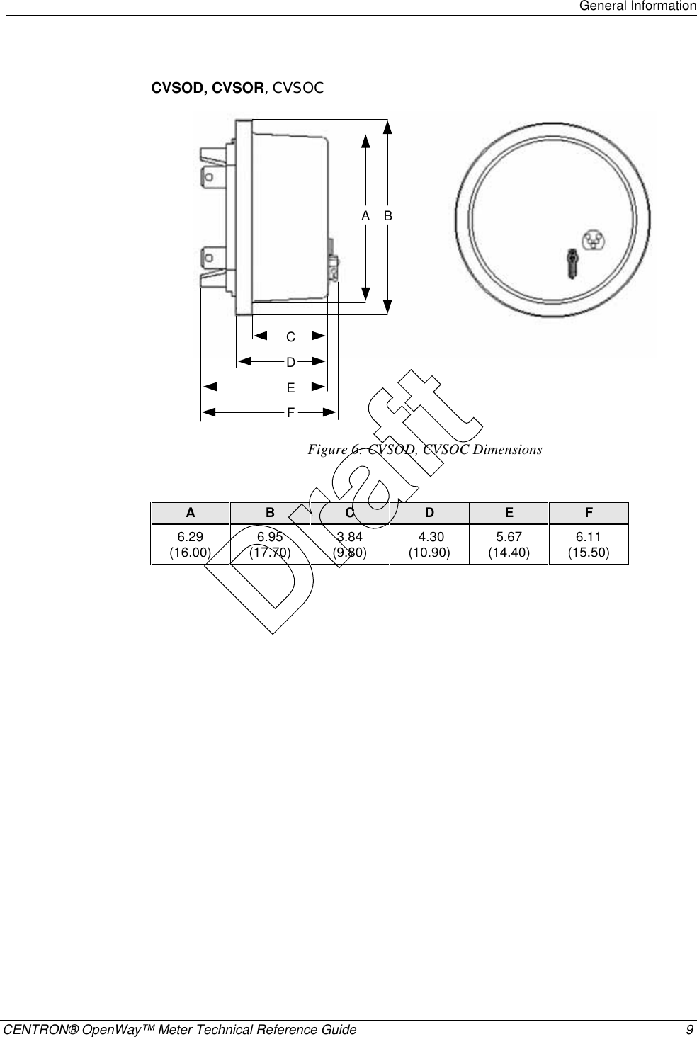
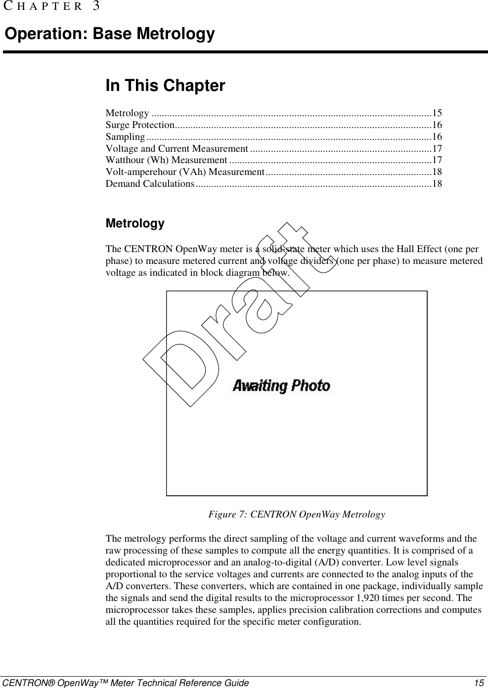
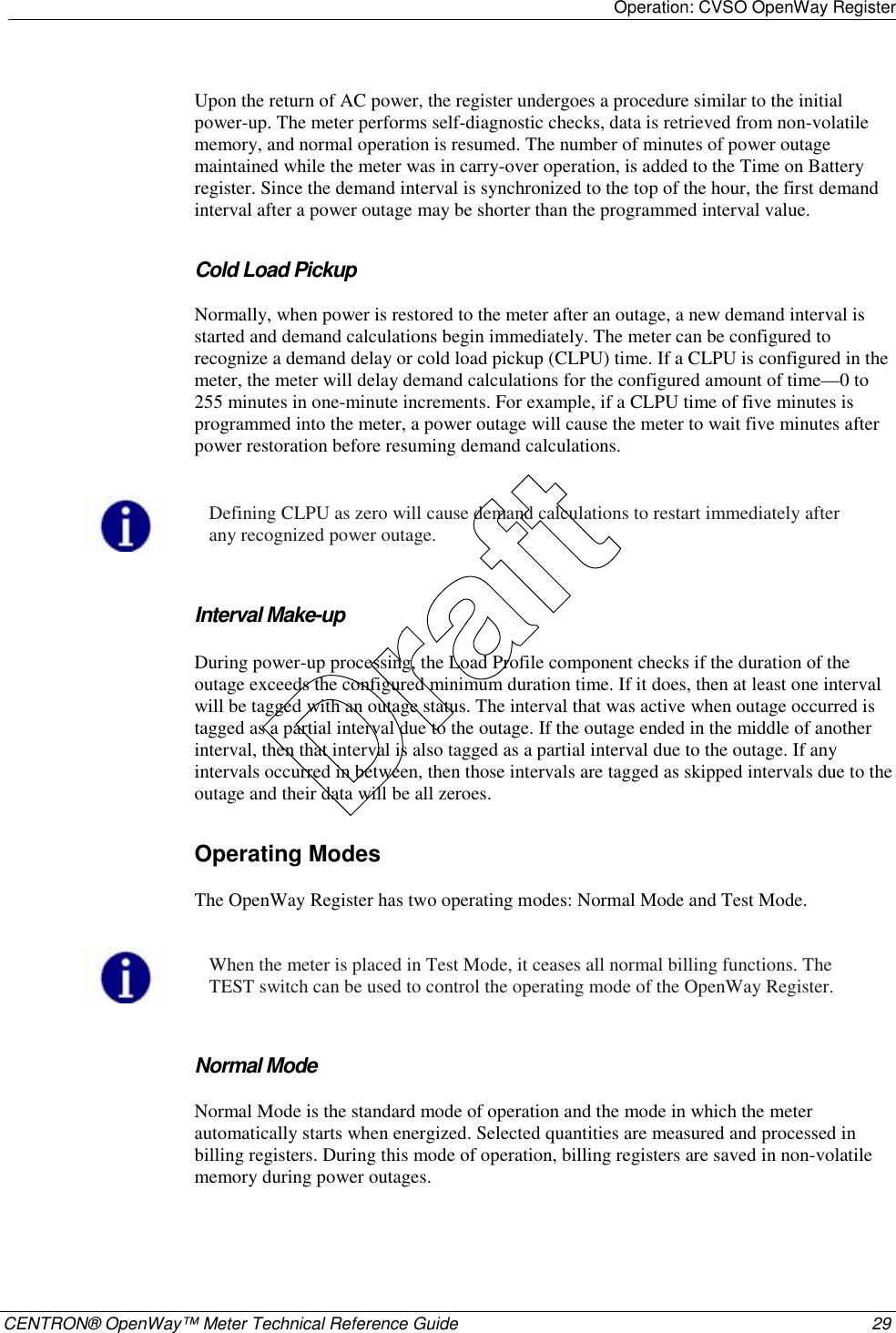
![Operation: CVSO OpenWay Register CENTRON® OpenWay™ Meter Technical Reference Guide 37 Any time-related activities, such as TOU rate changes or Daylight Savings Time (DST) changes that occur while the meter is in Test Mode, are performed upon exiting Test Mode. Test Alternate Display Mode Test Alternate Mode is functionally identical to Test Mode. To enter Test Alternate Mode, press the Test switch a second time. The “TEST” and “ALT” annunciators will be displayed. The meter will return to Normal Mode at the completion of Mode Time-out. Diagnostic Displays The user may program the behavior that the meter should exhibit for every specific error condition. The possible actions in order of increasing severity are to ignore the error (do not display the error code); scroll its error code (an error code is automatically displayed after each display item); or lock the display, showing only the error code (do not display anything else). Registers There are five register types in the D/T/L Register: Energy, Demand, Instantaneous, Self Read (or Snapshot), and Information. Energy Registers The D/T/L Register can measure numerous energy quantities (as shown in the table below) from which the user can configure any eight to be registered. If an energy register that is being used in the Load Profile is edited, the current interval for that quantity will be affected. Measured Energy Quantity Type Phases Directions watt-hours aggregate delivered received net uni-directional Varhours aggregate delivered received net net delivered net received Q1, Q4 VA-hours (vectorial or arithmetic [RMS]) aggregate delivered received lagging Draft](https://usermanual.wiki/Itron/AMI-2/User-Guide-715419-Page-48.png)
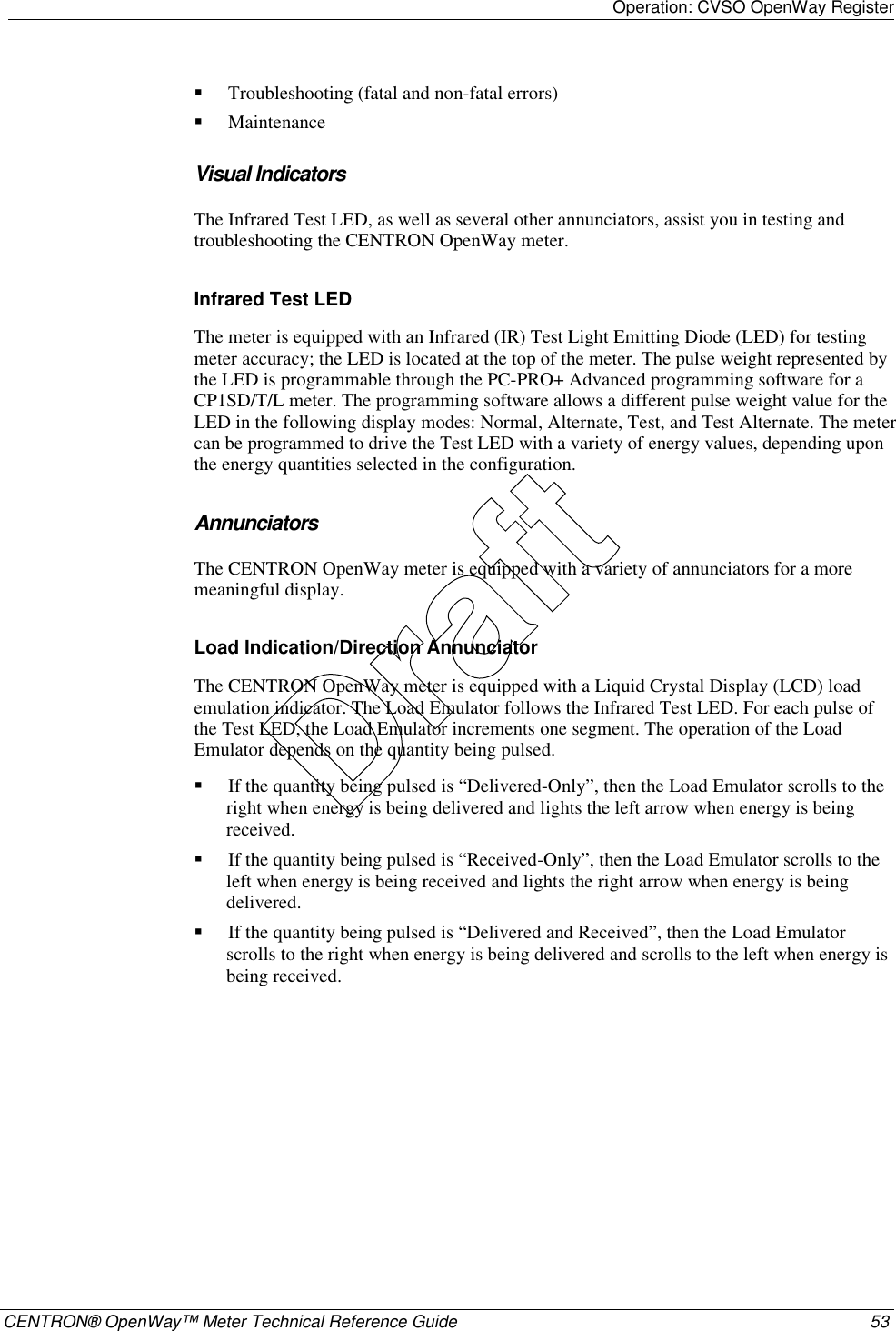
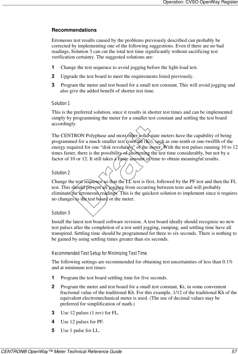
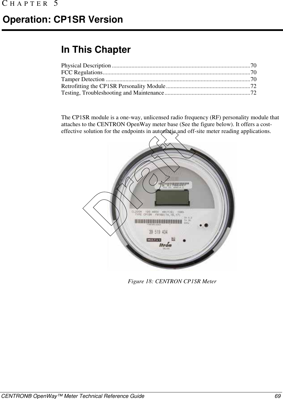
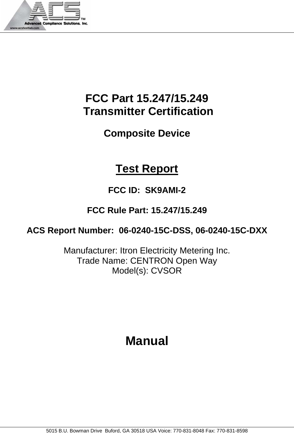
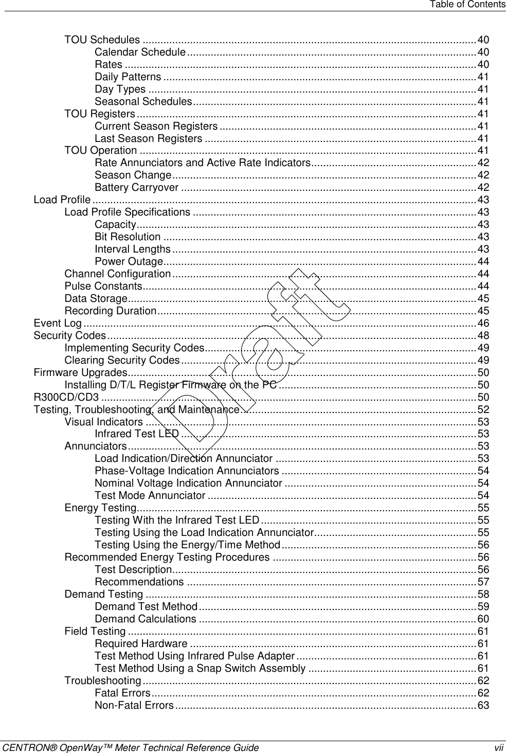
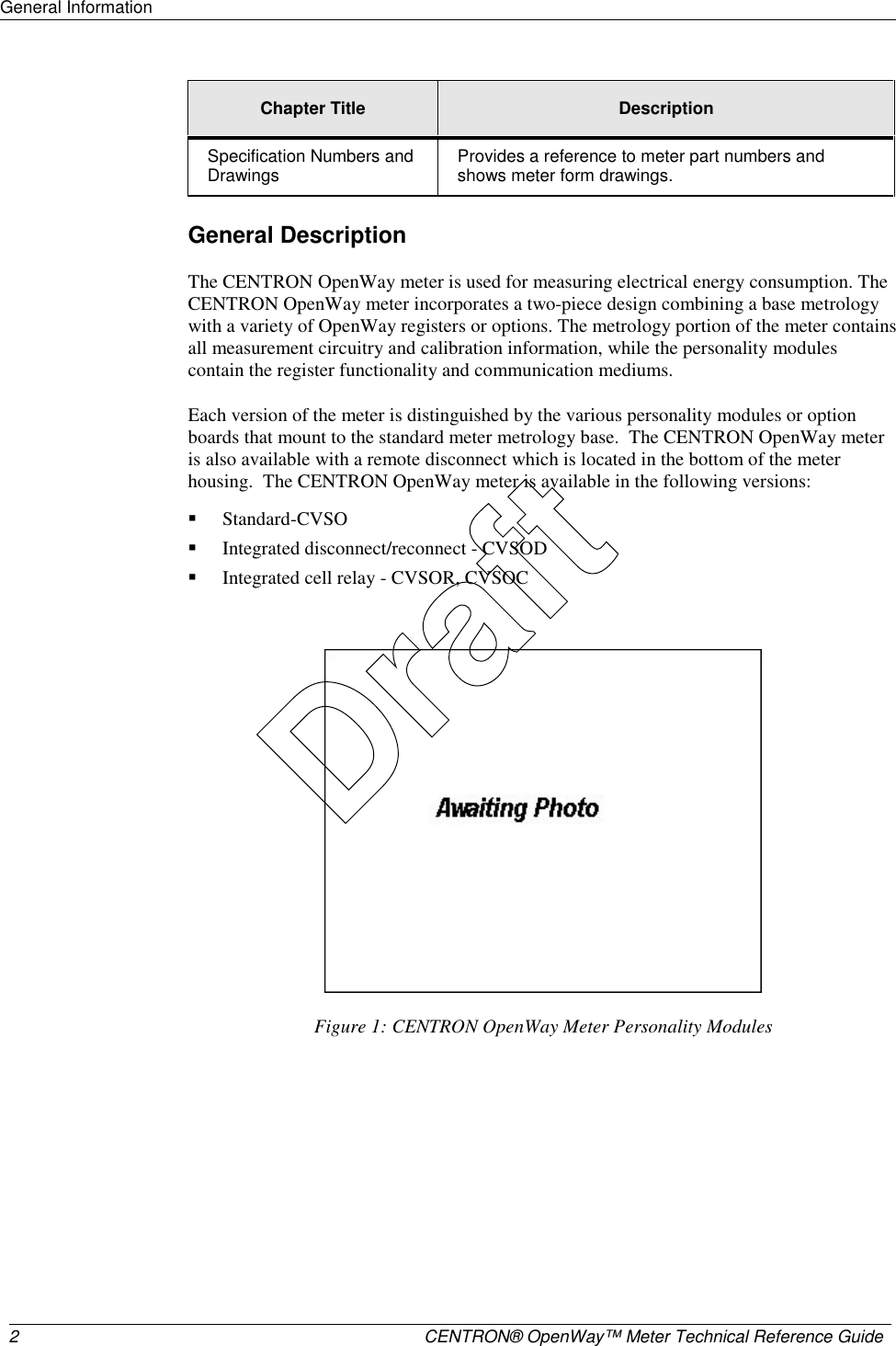
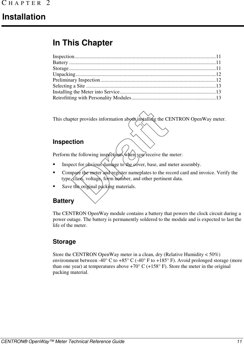
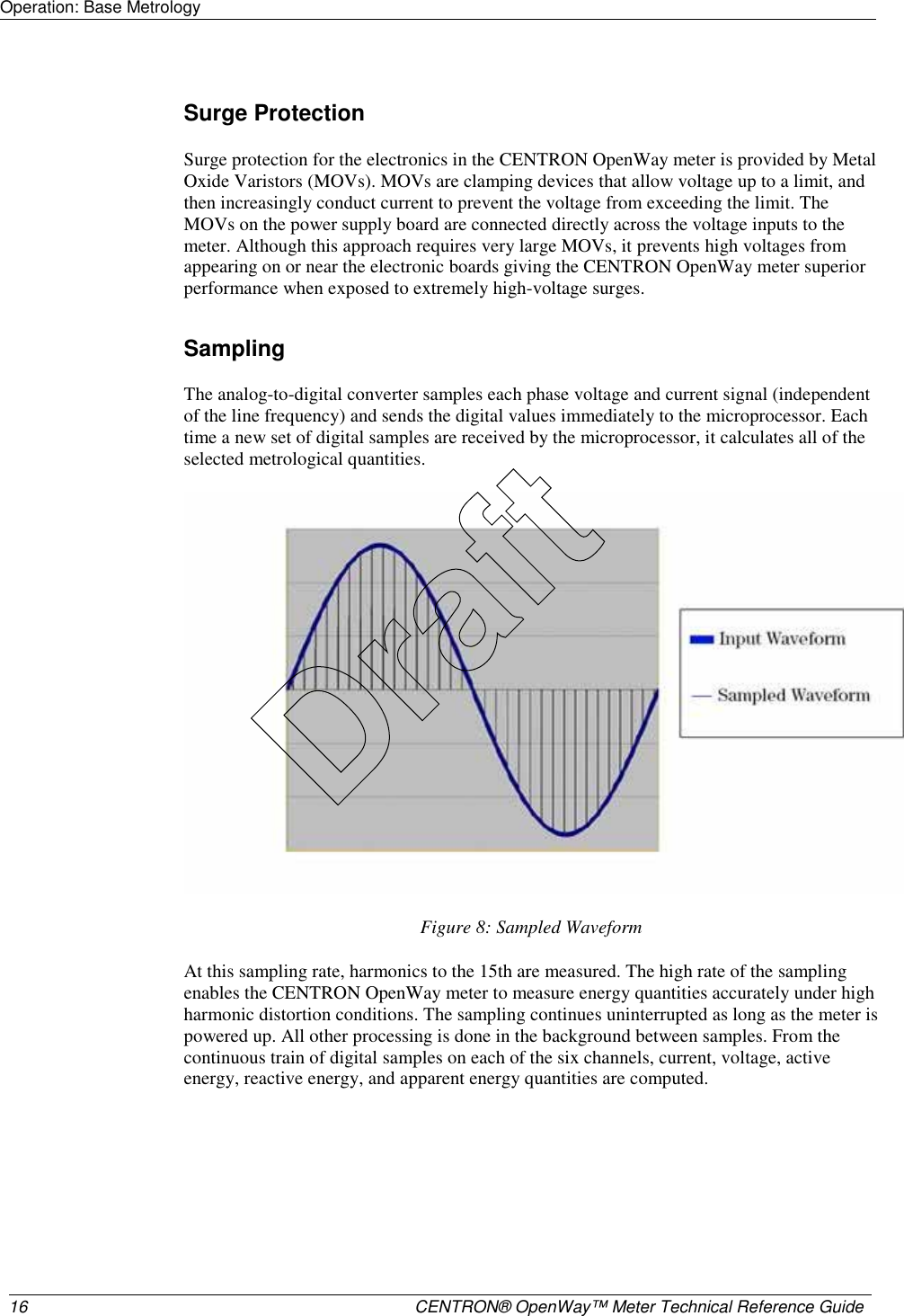
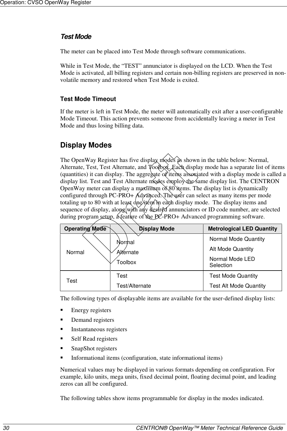
![Operation: CVSO OpenWay Register 38 CENTRON® OpenWay™ Meter Technical Reference Guide Measured Energy Quantity Type Phases Directions Volt-hours (Vh) phase A phase B phase C average Amp-hours (Ah) phase A phase B phase C V2h aggregate A2h aggregate Q-hours aggregate delivered received Demand Registers Demands can be calculated from any of the eight selected energy quantities. The user can configure up to ten demand registers. The D/T/L Register can compute three types of demand: Block Demand, Rolling Demand, or Thermal Demand. Measured Demand Quantity Type Demand Registers Phases Directions watt-hours Block, Rolling, Thermal aggregate delivered received net uni-directional Varhours Block, Rolling, Thermal aggregate delivered received net per quadrant VA-hours (vectorial or arithmetic [RMS]) Block, Rolling, Thermal aggregate delivered received lagging Amp-hours (Ah) Block phase A phase B phase C Draft](https://usermanual.wiki/Itron/AMI-2/User-Guide-715419-Page-49.png)
![Operation: CVSO OpenWay Register CENTRON® OpenWay™ Meter Technical Reference Guide 39 Instantaneous Registers The D/T/L Register is capable of displaying Primary or Secondary Instantaneous registers, with the following exceptions: Frequency, Power Factor (PF), and Phase Angles. The user can configure the CT and VT multipliers (transformer ratios) using PC-PRO+ Advanced programming software. Instantaneous Register Quantity Directions (Types) [Range] Phases W Signed (+) Delivered or (-) Received Aggregate Var Signed (+) Delivered or (-) Received Aggregate VA (Vectorial or Arithmetic) None Aggregate V None A, B, C A None A, B, C PF None Average Frequency None A Phase Angles Va = 0° Vb, Vc, Ia, Ib, Ic Self Read and Snapshot Registers There are up to fifteen self-read registers available in the D/T/L Register, depending on the particular version. All meters have two snapshot registers that store self read data triggered by a demand reset. Snapshot 1 is taken at the most recent demand reset. Snapshot 2 is the next most recent set of self read data at demand reset. Meters with time keeping functionality have an additional twelve self-reads registers used for scheduled self-reads, and one Last Season self-read register triggered at a season change in TOU meters. Information Registers The D/T/L Register also stores a significant amount of informational data. These non-registered values are listed in Informational Data. Interrogation and Programming Interrogation The meter can be interrogated via the ANSI C12.18 optical port using PSEM (ANSI C12.18-1996) protocol. Draft](https://usermanual.wiki/Itron/AMI-2/User-Guide-715419-Page-50.png)
![Operation: CVSO OpenWay Register CENTRON® OpenWay™ Meter Technical Reference Guide 45 Since the pulse weight value must be a multiple of 0.01 in the meter, 0.03 Wh could be programmed as the pulse weight (Ke) for the kWh channel in load profile in this example. Data Storage The D/T/L Register uses non-volatile flash memory to record load profile data. Data is stored in load profile memory at the end of each interval. Each channel has 16 bits written to load profile memory. For example, consider 8 channels of load profile. At the end of an interval, a 16-bit number is written into load profile memory for channel 1; a 16-bit number for channel 2 follows immediately; and so on, up to the last 16-bit number for channel 8, which follows immediately. The process continues for each interval until 128 intervals (one block or record) have been recorded. In addition to the profile data, each interval contains eight types of status bits written into each data interval. 1 Partial Interval—The status bit is set for a partial interval due to a time adjust, power outage, or beginning interval. 2 Long Interval—The status bit is set for a long interval due to a time adjust backwards. 3 Skipped Interval—The status bit is set for a skipped interval due to either a power outage, Test Mode, or time adjusted forward during the interval. 4 Test Mode—The status bit is set for Test Mode due to the meter being in test mode during the interval. 5 DST—The status bit is set for DST due to DST being in effect during the interval. 6 Power Outage—The status bit is set for each interval during which a power outage occurs (greater than the minimum time programmed in software). 7 Time Adjust Forward—The status bit is set for time adjust forward during the interval. 8 Time Adjust Backward—The status bit is set for time adjust backward during the interval. Refer to the PC-PRO+ Advanced online help for a list of Load Profile Status Codes. In addition to the interval profile data and the interval status data, each block contains a time tag specifying the month, day, hour, and second of the end of the data block. Recording Duration The following equation can be used to determine the recording duration of the load profile: Recording Duration (days) = (M x I x 1024) / (1,440 x [(2 x C + 2) + ((6 x C + 4) / 128)]) M = Memory size in kilobytes C = Number of channels I = Interval Length in minutes Draft](https://usermanual.wiki/Itron/AMI-2/User-Guide-715419-Page-56.png)