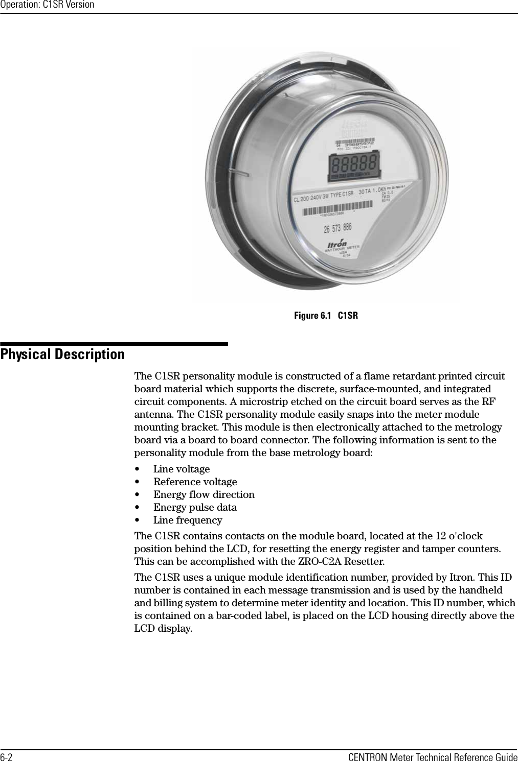
Itron C1A-2 ELECTRICITY METER WITH DUAL RF TRANSMITTER User Manual USERS MANUAL

Itron Electricity Metering, Inc. ELECTRICITY METER WITH DUAL RF TRANSMITTER USERS MANUAL

USERS MANUAL

                                          5015 B.U. Bowman Drive  Buford, GA 30518 USA Voice: 770-831-8048 Fax: 770-831-8598   FCC Part 15 Transmitter Certification Test Report  FCC ID:  SK9C1A-2  FCC Rule Part: 15.247  ACS Report Number:  04-0396-15C   Manufacturer: Itron Electricity Metering, Inc. Equipment Type:  Electricity Meter With Dual RF Transmitters Trade Name: CENTRON ™ ICARe Model: C1A-2      Manual
CENTRON® MeterTechnical Reference GuideEffective:  January 2005
ii CENTRON Meter Technical Reference GuideProprietary Rights NoticeThis manual is an unpublished work and contains the trade secrets and confidential infor-mation of Itron, Inc., which are not to be divulged to third parties and may not be repro-duced or transmitted in whole or part, in any form or by any means, electronic or mechanical for any purpose, without the express written permission of Itron, Inc.  All rights to designs or inventions disclosed herein, including the right to manufacture, are reserved to Itron, Inc.The information contained in this document is subject to change without notice. Itron, Inc. reserves the right to change the product specifications at any time without incurring any obligations.Trademarks Used in This ManualCENTRON, PC-PRO+, PRO-READ, and ReadOne are registered trademarks of Itron, Inc.Windows is a trademark of Microsoft Corporation.Cellnet is a registered trademark of Cellnet Technologies, Inc.CENTRON® Meter Technical Reference GuidePart Number: 100299GM-01Itron, Inc. Corporate Headquarters2818 North Sullivan RoadSpokane, WA 99216U.S.A.Tel: (509) 924-9900Fax: (509) 891-3355www.itron.comItron, Inc.Oconee Electricity Metering313-B North Highway 11West Union, SC 29696U.S.A.Tel: (864) 638-8300Fax: (864) 638-4950Copyright© 2004-2005Itron, Inc.All rights reserved.
CENTRON Meter Technical Reference Guide iiiCompliance With FCC RegulationsFCC Part 15, Class BThis equipment has been tested and found to comply with the limits for a Class B digital device, pursuant to Part 15 of the FCC rules. These rules are designed to provide reasonable protection against harmful interference when the equipment is operated in a residential/commercial environment. This equipment generates, uses, and can radiate radio frequency energy and, if not installed and used in accordance with the instructions, may cause harmful interference to radio communications. However, there is no guarantee that interference will not occur in a particular installation. If this equipment does cause harmful interference to radio or television reception, which can be determined by turning the equipment off and on, the user is encouraged to try to correct the interference by one or more of the following measures:• Re-orient or relocate the receiving antenna.• Increase the separation between the equipment and the receiver.• Connect the equipment into an outlet on a circuit different from that to which the receiver is connected.• Consult the dealer or an experienced radio/TV technician for help. This device complies with Part 15 of the FCC rules.THIS DEVICE COMPLIES WITH PART 15 OF THE FCC RULES. OPERATION IS SUBJECT TO THE FOLLOWING TWO CONDITIONS: (1) THIS DEVICE MAY NOT CAUSE HARMFUL INTERFERENCE, AND (2) THIS DEVICE MUST ACCEPT ANY INTERFERENCE RECEIVED, INCLUDING INTERFERENCE THAT MAY CAUSE UNDESIRED OPERATIONFCC Part 15, Subpart CWhen equipped with a radio transmitter option, this equipment has been tested and found to comply with the limits for an intentional radiator, pursuant to Part 15, Subpart C of the FCC Rules. This equipment generates, uses, and can radiate radio frequency energy. If not installed and used in accordance with the instructions, it may cause interference to radio communications.The limits are designed to provide reasonable protection against such interference in a resi-dential situation. However, there is no guarantee that interference will not occur in a partic-ular installation. If this equipment does cause interference to radio or television reception. which can be determined by turning the equipment on and off, the user is encouraged to try to correct the interference by one of more of the following measures:• Reorient or relocate the receiving antenna of the affected radio or television.• Increase the separation between the equipment and the affected receiver.• Connect the equipment and the affected receiver to power outlets on separate circuits.• Consult the dealer or an experienced radio/TV technician for help.Changes or modifications not expressly approved by Itron, Inc. could void the user’s author-ity to operate the equipment.RF Exposure InformationThis equipment complies with the FCC RF radiation requirements for uncontrolled environ-ments. To maintain compliance with these requirements, the antenna and any radiating ele-ments should be installed to ensure that a minimum separation distance of 20 cm is maintained from the general population.Canadian Interference Causing Equipment RegulationsThis Class B digital apparatus meets all requirements of the Canadian Interference Causing Equipment Regulations. Operation is subject to the following two conditions: (1) this device may not cause harmful interference, and (2) this device must accept any interference received, including interference that may cause undesired operation.
iv CENTRON Meter Technical Reference GuideCet appareillage numérique de la classe B répond à toutes les exigences de l'interférence canadienne causant des règlements d'équipement. L'opération est sujette aux deux condi-tions suivantes: (1) ce dispositif peut ne pas causer l'interférence nocive, et (2) ce dispositif doit accepter n'importe quelle interférence reçue, y compris l'interférence qui peut causer l'opération peu désirée.Factory Repair of MetersItron  recommends that all repairs be performed at the factory. Certain repairs may be per-formed by the user; however, unauthorized repairs will void any existing warranty. All sur-face mounted parts must be replaced by the factory.Repair of Meters Under WarrantyIf the meter is under warranty, then Itron, Inc. will repair the meter at no charge if the meter has failed due to components or workmanship. A return authorization number must be obtained before the equipment can be sent back to the factory. Contact your Itron Sales Representative for assistance.Repair of Meters Not Under WarrantyThe same procedure as above applies. Itron will charge for the necessary repairs based on the failure.Service Return AddressItron, Inc.Customer Repair Department313 North Highway 11 Dock CWest Union, SC 29696Recycling Information:The product you have purchased contains a battery (or batteries), circuit boards, and switches. Thebatteries are recyclable. At the end of the meter’s useful life, under various state and local laws,it may be illegal to dispose of certain components into the municipal waste system. Check withyour local solid waste officials for details about recycling options or proper disposal.Although polycarbonate is not a commonly recycled plastic, the recycling number for the polycar-bonate base is seven (7).
CENTRON Meter Technical Reference Guide vChapter 1 General InformationAbout This Manual  . . . . . . . . . . . . . . . . . . . . . . . . . . . . . . . . . . . . . . . . . . . . . . . . . . . . . . . . . . . . . . . . . . . . . . . . . . . .   1-1General Description   . . . . . . . . . . . . . . . . . . . . . . . . . . . . . . . . . . . . . . . . . . . . . . . . . . . . . . . . . . . . . . . . . . . . . . . . . . .   1-2Physical Description  . . . . . . . . . . . . . . . . . . . . . . . . . . . . . . . . . . . . . . . . . . . . . . . . . . . . . . . . . . . . . . . . . . . . . . . . . . .   1-3Meter Base   . . . . . . . . . . . . . . . . . . . . . . . . . . . . . . . . . . . . . . . . . . . . . . . . . . . . . . . . . . . . . . . . . . . . . . . . . . . . . .   1-3Personality Modules  . . . . . . . . . . . . . . . . . . . . . . . . . . . . . . . . . . . . . . . . . . . . . . . . . . . . . . . . . . . . . . . . . . . . . . .   1-4Product Availability  . . . . . . . . . . . . . . . . . . . . . . . . . . . . . . . . . . . . . . . . . . . . . . . . . . . . . . . . . . . . . . . . . . . . . . . . . . . .   1-4Battery  . . . . . . . . . . . . . . . . . . . . . . . . . . . . . . . . . . . . . . . . . . . . . . . . . . . . . . . . . . . . . . . . . . . . . . . . . . . . . . . . . .   1-4Covers   . . . . . . . . . . . . . . . . . . . . . . . . . . . . . . . . . . . . . . . . . . . . . . . . . . . . . . . . . . . . . . . . . . . . . . . . . . . . . . . . . .   1-5Outputs   . . . . . . . . . . . . . . . . . . . . . . . . . . . . . . . . . . . . . . . . . . . . . . . . . . . . . . . . . . . . . . . . . . . . . . . . . . . . . . . . .   1-5Display Functions   . . . . . . . . . . . . . . . . . . . . . . . . . . . . . . . . . . . . . . . . . . . . . . . . . . . . . . . . . . . . . . . . . . . . . . . . . . . . .   1-5Specifications  . . . . . . . . . . . . . . . . . . . . . . . . . . . . . . . . . . . . . . . . . . . . . . . . . . . . . . . . . . . . . . . . . . . . . . . . . . . . . . . .   1-5Electrical   . . . . . . . . . . . . . . . . . . . . . . . . . . . . . . . . . . . . . . . . . . . . . . . . . . . . . . . . . . . . . . . . . . . . . . . . . . . . . . . .   1-5Operating Environment   . . . . . . . . . . . . . . . . . . . . . . . . . . . . . . . . . . . . . . . . . . . . . . . . . . . . . . . . . . . . . . . . . . . . .   1-5Characteristic Data  . . . . . . . . . . . . . . . . . . . . . . . . . . . . . . . . . . . . . . . . . . . . . . . . . . . . . . . . . . . . . . . . . . . . . . . .   1-6Burden Data . . . . . . . . . . . . . . . . . . . . . . . . . . . . . . . . . . . . . . . . . . . . . . . . . . . . . . . . . . . . . . . . . . . . . . . . . . . . . .   1-6Technical Data  . . . . . . . . . . . . . . . . . . . . . . . . . . . . . . . . . . . . . . . . . . . . . . . . . . . . . . . . . . . . . . . . . . . . . . . . . . . .   1-7Dimensions   . . . . . . . . . . . . . . . . . . . . . . . . . . . . . . . . . . . . . . . . . . . . . . . . . . . . . . . . . . . . . . . . . . . . . . . . . . . . . .   1-7C1SD/C1ST/C1SL Dimensions  . . . . . . . . . . . . . . . . . . . . . . . . . . . . . . . . . . . . . . . . . . . . . . . . . . . . . . . . . . . .  1-8Shipping Weights   . . . . . . . . . . . . . . . . . . . . . . . . . . . . . . . . . . . . . . . . . . . . . . . . . . . . . . . . . . . . . . . . . . . . . . . . .   1-8Chapter 2 InstallationInspection  . . . . . . . . . . . . . . . . . . . . . . . . . . . . . . . . . . . . . . . . . . . . . . . . . . . . . . . . . . . . . . . . . . . . . . . . . . . . . . . . . . .   2-1Battery  . . . . . . . . . . . . . . . . . . . . . . . . . . . . . . . . . . . . . . . . . . . . . . . . . . . . . . . . . . . . . . . . . . . . . . . . . . . . . . . . . .   2-1Storage  . . . . . . . . . . . . . . . . . . . . . . . . . . . . . . . . . . . . . . . . . . . . . . . . . . . . . . . . . . . . . . . . . . . . . . . . . . . . . . . . . . . . .   2-1Unpacking  . . . . . . . . . . . . . . . . . . . . . . . . . . . . . . . . . . . . . . . . . . . . . . . . . . . . . . . . . . . . . . . . . . . . . . . . . . . . . . . . . . .   2-2Selecting a Site . . . . . . . . . . . . . . . . . . . . . . . . . . . . . . . . . . . . . . . . . . . . . . . . . . . . . . . . . . . . . . . . . . . . . . . . . . . . . . .   2-2Installing the Meter into Service   . . . . . . . . . . . . . . . . . . . . . . . . . . . . . . . . . . . . . . . . . . . . . . . . . . . . . . . . . . . . . . . . .   2-2Programming the C1SD,T,L Meter   . . . . . . . . . . . . . . . . . . . . . . . . . . . . . . . . . . . . . . . . . . . . . . . . . . . . . . . . . . . . . . . .   2-3Retrofitting with Personality Modules  . . . . . . . . . . . . . . . . . . . . . . . . . . . . . . . . . . . . . . . . . . . . . . . . . . . . . . . . . . . . .   2-3Chapter 3 Operation: Base MetrologyCENTRON 1S, 2S CL200, and 3S   . . . . . . . . . . . . . . . . . . . . . . . . . . . . . . . . . . . . . . . . . . . . . . . . . . . . . . . . . . . . . . . . .   3-1CENTRON 2S CL320, 4S, 12/25S  . . . . . . . . . . . . . . . . . . . . . . . . . . . . . . . . . . . . . . . . . . . . . . . . . . . . . . . . . . . . . . . . .   3-3Chapter 4 Operation: C1S VersionPhysical Description  . . . . . . . . . . . . . . . . . . . . . . . . . . . . . . . . . . . . . . . . . . . . . . . . . . . . . . . . . . . . . . . . . . . . . . . . . . .   4-1Registers  . . . . . . . . . . . . . . . . . . . . . . . . . . . . . . . . . . . . . . . . . . . . . . . . . . . . . . . . . . . . . . . . . . . . . . . . . . . . . . . . . . . .   4-2Kilowatt Hours . . . . . . . . . . . . . . . . . . . . . . . . . . . . . . . . . . . . . . . . . . . . . . . . . . . . . . . . . . . . . . . . . . . . . . . . . . . .   4-2Resetting Values  . . . . . . . . . . . . . . . . . . . . . . . . . . . . . . . . . . . . . . . . . . . . . . . . . . . . . . . . . . . . . . . . . . . . . . . . . .   4-2LCD Display Function   . . . . . . . . . . . . . . . . . . . . . . . . . . . . . . . . . . . . . . . . . . . . . . . . . . . . . . . . . . . . . . . . . . . . . . . . . .   4-4TABLE OF CONTENTS
Table of Contentsvi CENTRON Meter Technical Reference GuidePre-June 2003 LCDs  . . . . . . . . . . . . . . . . . . . . . . . . . . . . . . . . . . . . . . . . . . . . . . . . . . . . . . . . . . . . . . . . . . . . . . . . 4-4Post-June 2003 LCDs   . . . . . . . . . . . . . . . . . . . . . . . . . . . . . . . . . . . . . . . . . . . . . . . . . . . . . . . . . . . . . . . . . . . . . . . 4-6Non-Detented Register  . . . . . . . . . . . . . . . . . . . . . . . . . . . . . . . . . . . . . . . . . . . . . . . . . . . . . . . . . . . . . . . . . . 4-6Detented Register  . . . . . . . . . . . . . . . . . . . . . . . . . . . . . . . . . . . . . . . . . . . . . . . . . . . . . . . . . . . . . . . . . . . . . . 4-7Net Register . . . . . . . . . . . . . . . . . . . . . . . . . . . . . . . . . . . . . . . . . . . . . . . . . . . . . . . . . . . . . . . . . . . . . . . . . . . 4-7Segment Check  . . . . . . . . . . . . . . . . . . . . . . . . . . . . . . . . . . . . . . . . . . . . . . . . . . . . . . . . . . . . . . . . . . . . . . . . 4-7Factory Programming Options  . . . . . . . . . . . . . . . . . . . . . . . . . . . . . . . . . . . . . . . . . . . . . . . . . . . . . . . . . . . . . 4-8Chapter 5 Operation: C1SD, C1ST, and C1SL VersionsFeatures   . . . . . . . . . . . . . . . . . . . . . . . . . . . . . . . . . . . . . . . . . . . . . . . . . . . . . . . . . . . . . . . . . . . . . . . . . . . . . . . . . . . . . 5-1Controls and Indicators   . . . . . . . . . . . . . . . . . . . . . . . . . . . . . . . . . . . . . . . . . . . . . . . . . . . . . . . . . . . . . . . . . . . . . . . . . 5-2Modes of Operations  . . . . . . . . . . . . . . . . . . . . . . . . . . . . . . . . . . . . . . . . . . . . . . . . . . . . . . . . . . . . . . . . . . . . . . . . . . . 5-3Normal Mode   . . . . . . . . . . . . . . . . . . . . . . . . . . . . . . . . . . . . . . . . . . . . . . . . . . . . . . . . . . . . . . . . . . . . . . . . . . . . . 5-3Alternate Mode . . . . . . . . . . . . . . . . . . . . . . . . . . . . . . . . . . . . . . . . . . . . . . . . . . . . . . . . . . . . . . . . . . . . . . . . . . . . 5-3Test Mode  . . . . . . . . . . . . . . . . . . . . . . . . . . . . . . . . . . . . . . . . . . . . . . . . . . . . . . . . . . . . . . . . . . . . . . . . . . . . . . . . 5-3Low Power Mode   . . . . . . . . . . . . . . . . . . . . . . . . . . . . . . . . . . . . . . . . . . . . . . . . . . . . . . . . . . . . . . . . . . . . . . . . . . 5-5Displays   . . . . . . . . . . . . . . . . . . . . . . . . . . . . . . . . . . . . . . . . . . . . . . . . . . . . . . . . . . . . . . . . . . . . . . . . . . . . . . . . . . . . . 5-5Programmable Functions   . . . . . . . . . . . . . . . . . . . . . . . . . . . . . . . . . . . . . . . . . . . . . . . . . . . . . . . . . . . . . . . . . . . . . . . . 5-6Register Display Options . . . . . . . . . . . . . . . . . . . . . . . . . . . . . . . . . . . . . . . . . . . . . . . . . . . . . . . . . . . . . . . . . . . . . 5-7Self Reading   . . . . . . . . . . . . . . . . . . . . . . . . . . . . . . . . . . . . . . . . . . . . . . . . . . . . . . . . . . . . . . . . . . . . . . . . . . 5-8Last Season Registers  . . . . . . . . . . . . . . . . . . . . . . . . . . . . . . . . . . . . . . . . . . . . . . . . . . . . . . . . . . . . . . . . . . . 5-9Operating Parameters  . . . . . . . . . . . . . . . . . . . . . . . . . . . . . . . . . . . . . . . . . . . . . . . . . . . . . . . . . . . . . . . . . . . 5-9Informational Data . . . . . . . . . . . . . . . . . . . . . . . . . . . . . . . . . . . . . . . . . . . . . . . . . . . . . . . . . . . . . . . . . . . . . 5-10Test Mode Data  . . . . . . . . . . . . . . . . . . . . . . . . . . . . . . . . . . . . . . . . . . . . . . . . . . . . . . . . . . . . . . . . . . . . . . . 5-12Programming the Meter With a 200 Series Program   . . . . . . . . . . . . . . . . . . . . . . . . . . . . . . . . . . . . . . . . . . . . . . . . . 5-13Demand Reset   . . . . . . . . . . . . . . . . . . . . . . . . . . . . . . . . . . . . . . . . . . . . . . . . . . . . . . . . . . . . . . . . . . . . . . . . . . . . . . . 5-15Time-of-Use   . . . . . . . . . . . . . . . . . . . . . . . . . . . . . . . . . . . . . . . . . . . . . . . . . . . . . . . . . . . . . . . . . . . . . . . . . . . . . . . . . 5-15TOU Schedules  . . . . . . . . . . . . . . . . . . . . . . . . . . . . . . . . . . . . . . . . . . . . . . . . . . . . . . . . . . . . . . . . . . . . . . . . . . . 5-15Calendar Schedule   . . . . . . . . . . . . . . . . . . . . . . . . . . . . . . . . . . . . . . . . . . . . . . . . . . . . . . . . . . . . . . . . . . . . . . . . 5-15Rate Schedules   . . . . . . . . . . . . . . . . . . . . . . . . . . . . . . . . . . . . . . . . . . . . . . . . . . . . . . . . . . . . . . . . . . . . . . . 5-16Daily Schedules  . . . . . . . . . . . . . . . . . . . . . . . . . . . . . . . . . . . . . . . . . . . . . . . . . . . . . . . . . . . . . . . . . . . . . . . 5-16Seasonal Schedules   . . . . . . . . . . . . . . . . . . . . . . . . . . . . . . . . . . . . . . . . . . . . . . . . . . . . . . . . . . . . . . . . . . . 5-16Daylight Savings Time  . . . . . . . . . . . . . . . . . . . . . . . . . . . . . . . . . . . . . . . . . . . . . . . . . . . . . . . . . . . . . . . . . . 5-16Registers  . . . . . . . . . . . . . . . . . . . . . . . . . . . . . . . . . . . . . . . . . . . . . . . . . . . . . . . . . . . . . . . . . . . . . . . . . . . . . . . . 5-16Current Season Register  . . . . . . . . . . . . . . . . . . . . . . . . . . . . . . . . . . . . . . . . . . . . . . . . . . . . . . . . . . . . . . . . 5-16Last Season Registers  . . . . . . . . . . . . . . . . . . . . . . . . . . . . . . . . . . . . . . . . . . . . . . . . . . . . . . . . . . . . . . . . . . 5-17Load Profile Specifications . . . . . . . . . . . . . . . . . . . . . . . . . . . . . . . . . . . . . . . . . . . . . . . . . . . . . . . . . . . . . . . . . . . . . . 5-17Capacity . . . . . . . . . . . . . . . . . . . . . . . . . . . . . . . . . . . . . . . . . . . . . . . . . . . . . . . . . . . . . . . . . . . . . . . . . . . . . . . . . 5-17Bit Resolution  . . . . . . . . . . . . . . . . . . . . . . . . . . . . . . . . . . . . . . . . . . . . . . . . . . . . . . . . . . . . . . . . . . . . . . . . . . . . 5-17Interval Lengths . . . . . . . . . . . . . . . . . . . . . . . . . . . . . . . . . . . . . . . . . . . . . . . . . . . . . . . . . . . . . . . . . . . . . . . . . . . 5-18Power Outage  . . . . . . . . . . . . . . . . . . . . . . . . . . . . . . . . . . . . . . . . . . . . . . . . . . . . . . . . . . . . . . . . . . . . . . . . . . . . 5-18Channel Configurations . . . . . . . . . . . . . . . . . . . . . . . . . . . . . . . . . . . . . . . . . . . . . . . . . . . . . . . . . . . . . . . . . . . . . 5-18Data Storage  . . . . . . . . . . . . . . . . . . . . . . . . . . . . . . . . . . . . . . . . . . . . . . . . . . . . . . . . . . . . . . . . . . . . . . . . . . . . . 5-19Recording Duration  . . . . . . . . . . . . . . . . . . . . . . . . . . . . . . . . . . . . . . . . . . . . . . . . . . . . . . . . . . . . . . . . . . . . . . . . 5-19Optional Features  . . . . . . . . . . . . . . . . . . . . . . . . . . . . . . . . . . . . . . . . . . . . . . . . . . . . . . . . . . . . . . . . . . . . . . . . . . . . . 5-20Electronic Detent . . . . . . . . . . . . . . . . . . . . . . . . . . . . . . . . . . . . . . . . . . . . . . . . . . . . . . . . . . . . . . . . . . . . . . . . . . 5-20Expansion Port . . . . . . . . . . . . . . . . . . . . . . . . . . . . . . . . . . . . . . . . . . . . . . . . . . . . . . . . . . . . . . . . . . . . . . . . . . . . 5-20Security Codes   . . . . . . . . . . . . . . . . . . . . . . . . . . . . . . . . . . . . . . . . . . . . . . . . . . . . . . . . . . . . . . . . . . . . . . . . . . . 5-20Calculations   . . . . . . . . . . . . . . . . . . . . . . . . . . . . . . . . . . . . . . . . . . . . . . . . . . . . . . . . . . . . . . . . . . . . . . . . . . . . . . . . . 5-21
Table of ContentsCENTRON Meter Technical Reference Guide viiEnergy   . . . . . . . . . . . . . . . . . . . . . . . . . . . . . . . . . . . . . . . . . . . . . . . . . . . . . . . . . . . . . . . . . . . . . . . . . . . . . . . . .   5-21Demand  . . . . . . . . . . . . . . . . . . . . . . . . . . . . . . . . . . . . . . . . . . . . . . . . . . . . . . . . . . . . . . . . . . . . . . . . . . . . . . . .   5-21Demand Calculations  . . . . . . . . . . . . . . . . . . . . . . . . . . . . . . . . . . . . . . . . . . . . . . . . . . . . . . . . . . . . . . . . . .   5-22Power Procedures  . . . . . . . . . . . . . . . . . . . . . . . . . . . . . . . . . . . . . . . . . . . . . . . . . . . . . . . . . . . . . . . . . . . . . . . . . . . .   5-23Applying Power  . . . . . . . . . . . . . . . . . . . . . . . . . . . . . . . . . . . . . . . . . . . . . . . . . . . . . . . . . . . . . . . . . . . . . . . . . .   5-23Battery Life (Load Profile & TOU)   . . . . . . . . . . . . . . . . . . . . . . . . . . . . . . . . . . . . . . . . . . . . . . . . . . . . . . . . . . . .   5-23Example 1  . . . . . . . . . . . . . . . . . . . . . . . . . . . . . . . . . . . . . . . . . . . . . . . . . . . . . . . . . . . . . . . . . . . . . . . . . . .   5-24Example 2  . . . . . . . . . . . . . . . . . . . . . . . . . . . . . . . . . . . . . . . . . . . . . . . . . . . . . . . . . . . . . . . . . . . . . . . . . . .   5-25Example 3  . . . . . . . . . . . . . . . . . . . . . . . . . . . . . . . . . . . . . . . . . . . . . . . . . . . . . . . . . . . . . . . . . . . . . . . . . . .   5-26Low Battery Error  . . . . . . . . . . . . . . . . . . . . . . . . . . . . . . . . . . . . . . . . . . . . . . . . . . . . . . . . . . . . . . . . . . . . .   5-26Effectivity Date . . . . . . . . . . . . . . . . . . . . . . . . . . . . . . . . . . . . . . . . . . . . . . . . . . . . . . . . . . . . . . . . . . . . . . .   5-27Three Button Reset  . . . . . . . . . . . . . . . . . . . . . . . . . . . . . . . . . . . . . . . . . . . . . . . . . . . . . . . . . . . . . . . . . . . . . . . . . . .  5-27Option Boards  . . . . . . . . . . . . . . . . . . . . . . . . . . . . . . . . . . . . . . . . . . . . . . . . . . . . . . . . . . . . . . . . . . . . . . . . . . . . . . .   5-27CENTRON R300CD Operation  . . . . . . . . . . . . . . . . . . . . . . . . . . . . . . . . . . . . . . . . . . . . . . . . . . . . . . . . . . . . . . .   5-27Programming the R300CD Meter   . . . . . . . . . . . . . . . . . . . . . . . . . . . . . . . . . . . . . . . . . . . . . . . . . . . . . . . . . . . .   5-28Errors  . . . . . . . . . . . . . . . . . . . . . . . . . . . . . . . . . . . . . . . . . . . . . . . . . . . . . . . . . . . . . . . . . . . . . . . . . . . . . . . . . . . . . .   5-29Chapter 6 Operation: C1SR VersionPhysical Description  . . . . . . . . . . . . . . . . . . . . . . . . . . . . . . . . . . . . . . . . . . . . . . . . . . . . . . . . . . . . . . . . . . . . . . . . . . .   6-2Registers  . . . . . . . . . . . . . . . . . . . . . . . . . . . . . . . . . . . . . . . . . . . . . . . . . . . . . . . . . . . . . . . . . . . . . . . . . . . . . . . . . . . .   6-2Display  . . . . . . . . . . . . . . . . . . . . . . . . . . . . . . . . . . . . . . . . . . . . . . . . . . . . . . . . . . . . . . . . . . . . . . . . . . . . . . . . . .   6-2Electronic Detent  . . . . . . . . . . . . . . . . . . . . . . . . . . . . . . . . . . . . . . . . . . . . . . . . . . . . . . . . . . . . . . . . . . . . . . . . . .   6-3Resetting Values  . . . . . . . . . . . . . . . . . . . . . . . . . . . . . . . . . . . . . . . . . . . . . . . . . . . . . . . . . . . . . . . . . . . . . . . . . .   6-3Transmission Scheme  . . . . . . . . . . . . . . . . . . . . . . . . . . . . . . . . . . . . . . . . . . . . . . . . . . . . . . . . . . . . . . . . . . . . . . . . . .   6-4FCC Regulations . . . . . . . . . . . . . . . . . . . . . . . . . . . . . . . . . . . . . . . . . . . . . . . . . . . . . . . . . . . . . . . . . . . . . . . . . . .   6-4Tamper Detection  . . . . . . . . . . . . . . . . . . . . . . . . . . . . . . . . . . . . . . . . . . . . . . . . . . . . . . . . . . . . . . . . . . . . . . . . . . . . .   6-4Testing the CENTRON C1SR Tamper Counter  . . . . . . . . . . . . . . . . . . . . . . . . . . . . . . . . . . . . . . . . . . . . . . . . . . . .   6-5Retrofitting the C1SR Personality Module  . . . . . . . . . . . . . . . . . . . . . . . . . . . . . . . . . . . . . . . . . . . . . . . . . . . . . . . . . .   6-6Chapter 7 Operation: C1SC VersionPhysical Description  . . . . . . . . . . . . . . . . . . . . . . . . . . . . . . . . . . . . . . . . . . . . . . . . . . . . . . . . . . . . . . . . . . . . . . . . . . .   7-2Transmission Scheme  . . . . . . . . . . . . . . . . . . . . . . . . . . . . . . . . . . . . . . . . . . . . . . . . . . . . . . . . . . . . . . . . . . . . . . . . . .   7-2FCC Regulations   . . . . . . . . . . . . . . . . . . . . . . . . . . . . . . . . . . . . . . . . . . . . . . . . . . . . . . . . . . . . . . . . . . . . . . . . . . . . . .   7-3Display Functions   . . . . . . . . . . . . . . . . . . . . . . . . . . . . . . . . . . . . . . . . . . . . . . . . . . . . . . . . . . . . . . . . . . . . . . . . . . . . .   7-3Resetting Values  . . . . . . . . . . . . . . . . . . . . . . . . . . . . . . . . . . . . . . . . . . . . . . . . . . . . . . . . . . . . . . . . . . . . . . . . . . . . . .   7-4Programming the C1SC/CN1SC   . . . . . . . . . . . . . . . . . . . . . . . . . . . . . . . . . . . . . . . . . . . . . . . . . . . . . . . . . . . . . . . . . .  7-4Chapter 8 Testing, Troubleshooting, and MaintenanceTesting Support Features   . . . . . . . . . . . . . . . . . . . . . . . . . . . . . . . . . . . . . . . . . . . . . . . . . . . . . . . . . . . . . . . . . . . . . . .   8-1Infrared Test LED  . . . . . . . . . . . . . . . . . . . . . . . . . . . . . . . . . . . . . . . . . . . . . . . . . . . . . . . . . . . . . . . . . . . . . . . . . .   8-1Pulse Detector   . . . . . . . . . . . . . . . . . . . . . . . . . . . . . . . . . . . . . . . . . . . . . . . . . . . . . . . . . . . . . . . . . . . . . . . .   8-1Annunciators  . . . . . . . . . . . . . . . . . . . . . . . . . . . . . . . . . . . . . . . . . . . . . . . . . . . . . . . . . . . . . . . . . . . . . . . . . . . . .   8-2Watthour Annunciators   . . . . . . . . . . . . . . . . . . . . . . . . . . . . . . . . . . . . . . . . . . . . . . . . . . . . . . . . . . . . . . . . .   8-2TOU Rate Annunciators  . . . . . . . . . . . . . . . . . . . . . . . . . . . . . . . . . . . . . . . . . . . . . . . . . . . . . . . . . . . . . . . . .   8-2Test Mode Annunciator  . . . . . . . . . . . . . . . . . . . . . . . . . . . . . . . . . . . . . . . . . . . . . . . . . . . . . . . . . . . . . . . . .   8-3Testing with the Infrared Test LED   . . . . . . . . . . . . . . . . . . . . . . . . . . . . . . . . . . . . . . . . . . . . . . . . . . . . . . . . . . . .   8-3Testing Using the Disk Emulation Annunciator  . . . . . . . . . . . . . . . . . . . . . . . . . . . . . . . . . . . . . . . . . . . . . . . . . . .   8-4
Table of Contentsviii CENTRON Meter Technical Reference GuideRecommended Energy Testing Procedures   . . . . . . . . . . . . . . . . . . . . . . . . . . . . . . . . . . . . . . . . . . . . . . . . . . . . . . . . . . 8-4AEP Test Codes  . . . . . . . . . . . . . . . . . . . . . . . . . . . . . . . . . . . . . . . . . . . . . . . . . . . . . . . . . . . . . . . . . . . . . . . . . . . . 8-4Field Testing  . . . . . . . . . . . . . . . . . . . . . . . . . . . . . . . . . . . . . . . . . . . . . . . . . . . . . . . . . . . . . . . . . . . . . . . . . . . . . . . . . . 8-4Required Hardware  . . . . . . . . . . . . . . . . . . . . . . . . . . . . . . . . . . . . . . . . . . . . . . . . . . . . . . . . . . . . . . . . . . . . . . . . . 8-4Troubleshooting   . . . . . . . . . . . . . . . . . . . . . . . . . . . . . . . . . . . . . . . . . . . . . . . . . . . . . . . . . . . . . . . . . . . . . . . . . . . . . . . 8-5Error Codes (R300) . . . . . . . . . . . . . . . . . . . . . . . . . . . . . . . . . . . . . . . . . . . . . . . . . . . . . . . . . . . . . . . . . . . . . . . . . . 8-5Non-Fatal Error   . . . . . . . . . . . . . . . . . . . . . . . . . . . . . . . . . . . . . . . . . . . . . . . . . . . . . . . . . . . . . . . . . . . . . . . . 8-5Fatal Error   . . . . . . . . . . . . . . . . . . . . . . . . . . . . . . . . . . . . . . . . . . . . . . . . . . . . . . . . . . . . . . . . . . . . . . . . . . . . 8-5Error Codes (Demand, TOU, and Load Profile)   . . . . . . . . . . . . . . . . . . . . . . . . . . . . . . . . . . . . . . . . . . . . . . . . . . . . 8-5Non-Fatal Error Codes  . . . . . . . . . . . . . . . . . . . . . . . . . . . . . . . . . . . . . . . . . . . . . . . . . . . . . . . . . . . . . . . . . . . 8-6Fatal Error Codes  . . . . . . . . . . . . . . . . . . . . . . . . . . . . . . . . . . . . . . . . . . . . . . . . . . . . . . . . . . . . . . . . . . . . . . . 8-7Inspecting and Troubleshooting—General   . . . . . . . . . . . . . . . . . . . . . . . . . . . . . . . . . . . . . . . . . . . . . . . . . . . . . . . . . . 8-8Blank Display . . . . . . . . . . . . . . . . . . . . . . . . . . . . . . . . . . . . . . . . . . . . . . . . . . . . . . . . . . . . . . . . . . . . . . . . . . . . . . 8-8Time and Date Wrong (TOU or Load Profile Only)   . . . . . . . . . . . . . . . . . . . . . . . . . . . . . . . . . . . . . . . . . . . . . . . . . 8-8No Accumulation of kWh or kW  . . . . . . . . . . . . . . . . . . . . . . . . . . . . . . . . . . . . . . . . . . . . . . . . . . . . . . . . . . . . . . . 8-8Software Cannot Communicate with Module   . . . . . . . . . . . . . . . . . . . . . . . . . . . . . . . . . . . . . . . . . . . . . . . . . . . . 8-9Reed Switch Does Not Activate the Alternate Mode   . . . . . . . . . . . . . . . . . . . . . . . . . . . . . . . . . . . . . . . . . . . . . . 8-9Reset Mechanism Does Not Initiate Demand Reset  . . . . . . . . . . . . . . . . . . . . . . . . . . . . . . . . . . . . . . . . . . . . . . . 8-9Demand Reset Cannot be Initiated Through PC or Handheld . . . . . . . . . . . . . . . . . . . . . . . . . . . . . . . . . . . . . . . . . 8-9Test Mode Switch Does Not Place Module in Test Mode  . . . . . . . . . . . . . . . . . . . . . . . . . . . . . . . . . . . . . . . . . . 8-10Inspecting and Troubleshooting—C1S LCD and C1SR   . . . . . . . . . . . . . . . . . . . . . . . . . . . . . . . . . . . . . . . . . . . . . . . . 8-10Blank Display . . . . . . . . . . . . . . . . . . . . . . . . . . . . . . . . . . . . . . . . . . . . . . . . . . . . . . . . . . . . . . . . . . . . . . . . . . . . . 8-10Chapter 9 Specifications and DrawingsSpecifications . . . . . . . . . . . . . . . . . . . . . . . . . . . . . . . . . . . . . . . . . . . . . . . . . . . . . . . . . . . . . . . . . . . . . . . . . . . . . . . . . 9-1Drawings   . . . . . . . . . . . . . . . . . . . . . . . . . . . . . . . . . . . . . . . . . . . . . . . . . . . . . . . . . . . . . . . . . . . . . . . . . . . . . . . . . . . . 9-1
CENTRON Meter Technical Reference Guide ix1.1 Personality Modules . . . . . . . . . . . . . . . . . . . . . . . . . . . . . . . . . . . . . . . . . . . . . . . . . . . . . . . . . . . . . . . . . . . .   1-21.2 Form 1S, 120 Volt  . . . . . . . . . . . . . . . . . . . . . . . . . . . . . . . . . . . . . . . . . . . . . . . . . . . . . . . . . . . . . . . . . . . . . .   1-31.3 Form 2S, CL200 240 Volt . . . . . . . . . . . . . . . . . . . . . . . . . . . . . . . . . . . . . . . . . . . . . . . . . . . . . . . . . . . . . . . . .   1-31.4 Form 4S, 20 Amp Transformer-Rated  . . . . . . . . . . . . . . . . . . . . . . . . . . . . . . . . . . . . . . . . . . . . . . . . . . . . . . .   1-31.5 Personality Module Assembly. . . . . . . . . . . . . . . . . . . . . . . . . . . . . . . . . . . . . . . . . . . . . . . . . . . . . . . . . . . . .   1-41.6 Dimensions . . . . . . . . . . . . . . . . . . . . . . . . . . . . . . . . . . . . . . . . . . . . . . . . . . . . . . . . . . . . . . . . . . . . . . . . . . .   1-71.7 C1SD/C1ST/C1SL Dimensions  . . . . . . . . . . . . . . . . . . . . . . . . . . . . . . . . . . . . . . . . . . . . . . . . . . . . . . . . . . . .   1-82.1 Removing the Board-to-Board Connector . . . . . . . . . . . . . . . . . . . . . . . . . . . . . . . . . . . . . . . . . . . . . . . . . . . .   2-42.2 Removing the Register Module. . . . . . . . . . . . . . . . . . . . . . . . . . . . . . . . . . . . . . . . . . . . . . . . . . . . . . . . . . . .   2-42.3 New Module Snap-in  . . . . . . . . . . . . . . . . . . . . . . . . . . . . . . . . . . . . . . . . . . . . . . . . . . . . . . . . . . . . . . . . . . .   2-52.4 Circuit Board Notches . . . . . . . . . . . . . . . . . . . . . . . . . . . . . . . . . . . . . . . . . . . . . . . . . . . . . . . . . . . . . . . . . . .   2-52.5 Board-to-Board Connector, Bottom . . . . . . . . . . . . . . . . . . . . . . . . . . . . . . . . . . . . . . . . . . . . . . . . . . . . . . . . .   2-62.6 Board-to-Board Connector, Top . . . . . . . . . . . . . . . . . . . . . . . . . . . . . . . . . . . . . . . . . . . . . . . . . . . . . . . . . . . .   2-63.1 Power Measurement Principle in 2S. . . . . . . . . . . . . . . . . . . . . . . . . . . . . . . . . . . . . . . . . . . . . . . . . . . . . . . .   3-23.2 Simplified CENTRON Architecture . . . . . . . . . . . . . . . . . . . . . . . . . . . . . . . . . . . . . . . . . . . . . . . . . . . . . . . . .   3-33.3 Hall Cells and ADCs  . . . . . . . . . . . . . . . . . . . . . . . . . . . . . . . . . . . . . . . . . . . . . . . . . . . . . . . . . . . . . . . . . . . .   3-44.1 C1S LCD Personality Module  . . . . . . . . . . . . . . . . . . . . . . . . . . . . . . . . . . . . . . . . . . . . . . . . . . . . . . . . . . . . .   4-14.2 Mounted LCD Register  . . . . . . . . . . . . . . . . . . . . . . . . . . . . . . . . . . . . . . . . . . . . . . . . . . . . . . . . . . . . . . . . . .   4-24.3 ZRO-C2A Resetter Connected to the CENTRON . . . . . . . . . . . . . . . . . . . . . . . . . . . . . . . . . . . . . . . . . . . . . . .   4-34.4 Reverse Side of ZRO Resetter. . . . . . . . . . . . . . . . . . . . . . . . . . . . . . . . . . . . . . . . . . . . . . . . . . . . . . . . . . . . .   4-44.5 Pre-June 2003 LCD . . . . . . . . . . . . . . . . . . . . . . . . . . . . . . . . . . . . . . . . . . . . . . . . . . . . . . . . . . . . . . . . . . . . .   4-44.6 LCD Display without Segment Check . . . . . . . . . . . . . . . . . . . . . . . . . . . . . . . . . . . . . . . . . . . . . . . . . . . . . . .   4-54.7 LCD Display with Segment Check. . . . . . . . . . . . . . . . . . . . . . . . . . . . . . . . . . . . . . . . . . . . . . . . . . . . . . . . . .   4-54.8 Post-June 2003 LCD  . . . . . . . . . . . . . . . . . . . . . . . . . . . . . . . . . . . . . . . . . . . . . . . . . . . . . . . . . . . . . . . . . . . .   4-64.9 Non-Detented Register . . . . . . . . . . . . . . . . . . . . . . . . . . . . . . . . . . . . . . . . . . . . . . . . . . . . . . . . . . . . . . . . . .   4-64.10 Delivered kWh with Detent Enabled. . . . . . . . . . . . . . . . . . . . . . . . . . . . . . . . . . . . . . . . . . . . . . . . . . . . . . . .   4-74.11 Net kWh  . . . . . . . . . . . . . . . . . . . . . . . . . . . . . . . . . . . . . . . . . . . . . . . . . . . . . . . . . . . . . . . . . . . . . . . . . . . . .   4-74.12 Segment Test. . . . . . . . . . . . . . . . . . . . . . . . . . . . . . . . . . . . . . . . . . . . . . . . . . . . . . . . . . . . . . . . . . . . . . . . . .   4-75.1 C1SL Meter with Cover . . . . . . . . . . . . . . . . . . . . . . . . . . . . . . . . . . . . . . . . . . . . . . . . . . . . . . . . . . . . . . . . . .   5-15.2 C1SL Controls  . . . . . . . . . . . . . . . . . . . . . . . . . . . . . . . . . . . . . . . . . . . . . . . . . . . . . . . . . . . . . . . . . . . . . . . . .   5-25.3 Test Mode . . . . . . . . . . . . . . . . . . . . . . . . . . . . . . . . . . . . . . . . . . . . . . . . . . . . . . . . . . . . . . . . . . . . . . . . . . . .   5-45.4 Display. . . . . . . . . . . . . . . . . . . . . . . . . . . . . . . . . . . . . . . . . . . . . . . . . . . . . . . . . . . . . . . . . . . . . . . . . . . . . . .   5-55.5 Program File Export . . . . . . . . . . . . . . . . . . . . . . . . . . . . . . . . . . . . . . . . . . . . . . . . . . . . . . . . . . . . . . . . . . . .   5-135.6 Program File Export Type. . . . . . . . . . . . . . . . . . . . . . . . . . . . . . . . . . . . . . . . . . . . . . . . . . . . . . . . . . . . . . . .   5-145.7 Import Screen  . . . . . . . . . . . . . . . . . . . . . . . . . . . . . . . . . . . . . . . . . . . . . . . . . . . . . . . . . . . . . . . . . . . . . . . .   5-145.8 CENTRON C1ST/L Battery Life . . . . . . . . . . . . . . . . . . . . . . . . . . . . . . . . . . . . . . . . . . . . . . . . . . . . . . . . . . .   5-245.9 Example 1  . . . . . . . . . . . . . . . . . . . . . . . . . . . . . . . . . . . . . . . . . . . . . . . . . . . . . . . . . . . . . . . . . . . . . . . . . . .   5-255.10 Example 2  . . . . . . . . . . . . . . . . . . . . . . . . . . . . . . . . . . . . . . . . . . . . . . . . . . . . . . . . . . . . . . . . . . . . . . . . . . .   5-255.11 Example 3  . . . . . . . . . . . . . . . . . . . . . . . . . . . . . . . . . . . . . . . . . . . . . . . . . . . . . . . . . . . . . . . . . . . . . . . . . . .   5-265.12 CENTRON TOU Personality Module with R300CD Option . . . . . . . . . . . . . . . . . . . . . . . . . . . . . . . . . . . . . .  5-286.1 C1SR  . . . . . . . . . . . . . . . . . . . . . . . . . . . . . . . . . . . . . . . . . . . . . . . . . . . . . . . . . . . . . . . . . . . . . . . . . . . . . . . .   6-16.2 C1SR LCD. . . . . . . . . . . . . . . . . . . . . . . . . . . . . . . . . . . . . . . . . . . . . . . . . . . . . . . . . . . . . . . . . . . . . . . . . . . . .   6-26.3 CENTRON C1SR Transmission Cycle. . . . . . . . . . . . . . . . . . . . . . . . . . . . . . . . . . . . . . . . . . . . . . . . . . . . . . . .   6-46.4 C1SR FCC Label Location  . . . . . . . . . . . . . . . . . . . . . . . . . . . . . . . . . . . . . . . . . . . . . . . . . . . . . . . . . . . . . . . .   6-67.1 C1SC  . . . . . . . . . . . . . . . . . . . . . . . . . . . . . . . . . . . . . . . . . . . . . . . . . . . . . . . . . . . . . . . . . . . . . . . . . . . . . . . .   7-17.2 CellNet Telemetry . . . . . . . . . . . . . . . . . . . . . . . . . . . . . . . . . . . . . . . . . . . . . . . . . . . . . . . . . . . . . . . . . . . . . .   7-37.3 C1SC LCD. . . . . . . . . . . . . . . . . . . . . . . . . . . . . . . . . . . . . . . . . . . . . . . . . . . . . . . . . . . . . . . . . . . . . . . . . . . . .   7-47.4 C1SC/CN1SC Programming Port Location  . . . . . . . . . . . . . . . . . . . . . . . . . . . . . . . . . . . . . . . . . . . . . . . . . . .  7-5LIST OF FIGURESFigure Figure Titles Page
List of FiguresxCENTRON Meter Technical Reference Guide8.1 LED Location . . . . . . . . . . . . . . . . . . . . . . . . . . . . . . . . . . . . . . . . . . . . . . . . . . . . . . . . . . . . . . . . . . . . . . . . . . . 8-18.2 Pulse Detector  . . . . . . . . . . . . . . . . . . . . . . . . . . . . . . . . . . . . . . . . . . . . . . . . . . . . . . . . . . . . . . . . . . . . . . . . . 8-28.3 TOU Rate Annunciators  . . . . . . . . . . . . . . . . . . . . . . . . . . . . . . . . . . . . . . . . . . . . . . . . . . . . . . . . . . . . . . . . . . 8-39.1 Form 1S Wiring Diagram  . . . . . . . . . . . . . . . . . . . . . . . . . . . . . . . . . . . . . . . . . . . . . . . . . . . . . . . . . . . . . . . . . 9-19.2 Form 2S Wiring Diagram  . . . . . . . . . . . . . . . . . . . . . . . . . . . . . . . . . . . . . . . . . . . . . . . . . . . . . . . . . . . . . . . . . 9-29.3 Form 3S Wiring Diagram  . . . . . . . . . . . . . . . . . . . . . . . . . . . . . . . . . . . . . . . . . . . . . . . . . . . . . . . . . . . . . . . . . 9-29.4 Form 4S Wiring Diagram  . . . . . . . . . . . . . . . . . . . . . . . . . . . . . . . . . . . . . . . . . . . . . . . . . . . . . . . . . . . . . . . . . 9-39.5 Form 12S Wiring Diagram  . . . . . . . . . . . . . . . . . . . . . . . . . . . . . . . . . . . . . . . . . . . . . . . . . . . . . . . . . . . . . . . . 9-39.6 Form 25S Wiring Diagram  . . . . . . . . . . . . . . . . . . . . . . . . . . . . . . . . . . . . . . . . . . . . . . . . . . . . . . . . . . . . . . . . 9-4Figure Figure Titles Page
CENTRON Meter Technical Reference Guide xi1.1 Outer Cover Configurations . . . . . . . . . . . . . . . . . . . . . . . . . . . . . . . . . . . . . . . . . . . . . . . . . . . . . . . . . . . . . . . . . . . . . . . . 1-55.1 LCD Display Items  . . . . . . . . . . . . . . . . . . . . . . . . . . . . . . . . . . . . . . . . . . . . . . . . . . . . . . . . . . . . . . . . . . . . . . . . . . . . . . . 5-65.2 Register Display Formats . . . . . . . . . . . . . . . . . . . . . . . . . . . . . . . . . . . . . . . . . . . . . . . . . . . . . . . . . . . . . . . . . . . . . . . . . . 5-85.3 Programmable Parameters. . . . . . . . . . . . . . . . . . . . . . . . . . . . . . . . . . . . . . . . . . . . . . . . . . . . . . . . . . . . . . . . . . . . . . . . . 5-95.4 Information Data Items  . . . . . . . . . . . . . . . . . . . . . . . . . . . . . . . . . . . . . . . . . . . . . . . . . . . . . . . . . . . . . . . . . . . . . . . . . . 5-105.5 Test Mode Data Items . . . . . . . . . . . . . . . . . . . . . . . . . . . . . . . . . . . . . . . . . . . . . . . . . . . . . . . . . . . . . . . . . . . . . . . . . . . 5-125.6 Recording Duration for 32Kb . . . . . . . . . . . . . . . . . . . . . . . . . . . . . . . . . . . . . . . . . . . . . . . . . . . . . . . . . . . . . . . . . . . . . . 5-206.1 ReadOne Pro Tamper Count . . . . . . . . . . . . . . . . . . . . . . . . . . . . . . . . . . . . . . . . . . . . . . . . . . . . . . . . . . . . . . . . . . . . . . . . 6-58.1 AEP Test Codes. . . . . . . . . . . . . . . . . . . . . . . . . . . . . . . . . . . . . . . . . . . . . . . . . . . . . . . . . . . . . . . . . . . . . . . . . . . . . . . . . . 8-48.2 Error Codes. . . . . . . . . . . . . . . . . . . . . . . . . . . . . . . . . . . . . . . . . . . . . . . . . . . . . . . . . . . . . . . . . . . . . . . . . . . . . . . . . . . . . 8-58.3 Non-Fatal Error Codes . . . . . . . . . . . . . . . . . . . . . . . . . . . . . . . . . . . . . . . . . . . . . . . . . . . . . . . . . . . . . . . . . . . . . . . . . . . . 8-68.4 Fatal Error Codes . . . . . . . . . . . . . . . . . . . . . . . . . . . . . . . . . . . . . . . . . . . . . . . . . . . . . . . . . . . . . . . . . . . . . . . . . . . . . . . . 8-7LIST OF TABLESTable Table Titles Page
List of Tablesxii CENTRON Meter Technical Reference GuideNotes:
CENTRON Meter Technical Reference Guide 1-1Chapter 1 General InformationThis technical reference guide explains the installation, operation, and maintenance of the Itron CENTRON® meter family. Itron urges you to read the entire manual before attempting installation, testing, operation, or maintenance of a meter. To operate the Itron PC-PRO+® Programming Software and the PRO-READ® handheld reader programmer discussed in this manual, refer to their respective user manuals.About This ManualThis manual contains the following information as listed in the chapter descriptions below:Chapter 1 General InformationProvides a general description, operation, physical and functional descriptions, and complete meter specifications.Chapter 2 InstallationGives instructions for the proper handling and installation.Chapter 3 Operation: BaseDescribes the measurement technique used for the base on the CENTRON meter.Chapter 4 Operation: C1SProvides a physical description and operational characteristics of the basic watthour (kWh) only meter.Chapter 5 Operation:C1SD, C1ST, C1SLProvides detailed information and theoretical operation for Demand (C1SD), Time-of-Use (C1ST), and Load Profile (C1SL) versions. Gives step-by-step procedures for accessing the three operational modes and associated displays.Chapter 6 Operation: C1SRProvides a physical description and the operational characteristics of the R300 900 MHz radio frequency personality module.Chapter 7 Operation: C1SCProvides a physical description and the operational characteristics of the CellNet personality module.Chapter 8 Testing, Troubleshooting, and MaintenanceProvides an explanation of the testing, troubleshooting, and maintenance of the CENTRON meter.Chapter 9 Specification Numbers and DrawingsProvides a reference to meter part numbers as well as CENTRON wiring diagrams.
General Information1-2 CENTRON Meter Technical Reference GuideGeneral DescriptionThe CENTRON meter family is a solid-state, singlephase and network meter used for measuring electrical energy consumption. The CENTRON incorporates a two-piece design combining a base metrology with a variety of personality modules that snap on the standard meter base. Utilizing the Hall Effect technology for accurate power measurement, the metrology portion of the meter contains all measurement circuitry and calibration information, while the personality modules contain the register functionality and communication mediums. Each version of the meter is distinguished by the various personality modules that mount to the standard meter metrology base (see Figure 1.1) The personality modules available include the following versions:• Energy only—C1S (LCD)• Demand—C1SD• Time-of-Use (TOU) with Demand—C1ST• Load Profile with TOU and Demand—C1SL• Energy only with radio frequency AMR—C1SR• CellNet Fixed Network—C1SC• Energy plus demand with radio frequency AMR - R300CDFigure 1.1   Personality Modules
General InformationCENTRON Meter Technical Reference Guide 1-3Physical DescriptionThe CENTRON meter features a common meter base to which various personality modules are attached. The covers come in configurations of polycarbonate and glass. Meter BaseThe CENTRON meter base contains all of the measurement circuitry and calibration information on the metrology board.The meter base assembly includes two current conductors, a flux-directing core, a Hall Effect device, the metrology circuit board, and the ultrasonically welded module support. The base also contains a MOV, metal oxide varistor, which is used to protect the meter from line surges.Meter bases are built specific to the metering form and are available in Form 1S, 2S CL200, 2S CL320, 3S 120V, 3S 240V, 4S, and 12/25S configurations.Examples are shown in Figure 1.2, Figure 1.3, and Figure 1.4.Figure 1.2   Form 1S, 120 Volt Figure 1.3   Form 2S, CL200 240 VoltFigure 1.4   Form 4S, 20 Amp Transformer-Rated
General Information1-4 CENTRON Meter Technical Reference GuidePersonality ModulesAll of the personality modules in the CENTRON meter family snap into the module holder located on the standard meter base (see Figure 1.5). From the base metrology, the energy data is transmitted to the personality modules, which contain the meter display, communication mediums, and register functionality.Figure 1.5   Personality Module AssemblyProduct AvailabilityThe current offerings for the CENTRON are:BatteryThe CENTRON C1ST and C1SL modules contain a battery that powers the clock circuit during a power outage. The battery is permanently soldered to the module and is expected to last the life of the module. Refer to Chapter 5,"Operation: C1SD, C1ST, and C1SL Versions" for detailed battery information.Metrology Class 100, 120V, Form 1SClass 200, 240V, Form 2SClass 320, 240V, Form 2SClass 20, 120V, Form 3SClass 20, 240V, Form 3SClass 20, 240V, Form 4SClass 200, 120V, Form 12SClass 200, 120V, Form 25SPersonality ModulesC1S—LCD (5x1 or 4x10)C1SR—R300C (Radio Frequency)C1SC—CellNet Data SystemC1SD—DemandC1ST—Time-of-Use (TOU)C1SL—Load ProfileOption Boards R300CD
General InformationCENTRON Meter Technical Reference Guide 1-5CoversThe outer cover configurations available for CENTRON meter family are described in Table 1.1.OutputsThe C1SD, C1ST, and C1SL personality modules are available input/output-ready (I/O-ready). These modules contain circuitry that allows future functionality expansion through I/O modules.Display FunctionsThe C1S and C1SR modules can display kWh readings in either a 5x1 or 4x10 configuration.The C1SD, C1ST, and C1SL modules can display a maximum of 32 Normal, 32 Alternate, and 8 Test display items, up to a total of 48 items.SpecificationsElectricalOperating EnvironmentTable 1.1 Outer Cover ConfigurationsMeter Versions Cover OptionsPolycarbonate GlassC1S, C1SR, C1SC Standard OptionalC1SD, C1ST, C1SL Including Demand Reset+ Optical Tower Not AvailableVoltage Rating 120V, 240VOperating Voltage ± 20% (60 Hz); ± 10% (50 Hz)Frequency 60 Hz, 50 HzOperating Range ± 3 HzBattery Voltage 3.6 V nominal (C1ST, C1SL only)Operating Range 2.7V - 3.8VCarryover 8 year cumulative and 15 year shelf lifeTemperature -40°C to +85°CHumidity 0% to 95% non-condensingAccuracy ± 0.5% @ unity power factor± 0.5% @ 50% power factorTransient/Surge Suppression ANSI C37.90.1 - 1989IEC 61000-4-4ANSI C62.45 - 1992
General Information1-6 CENTRON Meter Technical Reference GuideCharacteristic DataBurden DataTo get the watt loss or VA of the overall product, add the metrology watt loss to the register watt loss and option board watt loss.Starting Watts2S CL200 5W1S, 2S CL320, 12S, 25S 10W3S CL20 1.2W4S CL20 2.4WTemperature Rise Meets ANSI C12.1 Section 4.7.2.9Metrology Voltage Watt Loss VA1S 120 0.45 3.72S Class 200 240 0.45 7.22S Class 320 240 0.65 10.23S 240 0.65 10.24S 240 0.65 10.212S/25S 120 0.65 5.4240V Register LCD R300 CellNet D/T/LWatt Loss 0.01 1.34 1.34 0.90VA — 0.25 0.25 14.76120V Register LCD R300 CellNet D/T/LWatt Loss 0.01 0.62 0.62 0.90VA — 0.14 0.14 11.1120V Option Board R300CDWatt Loss 2.2VA 23240V Option BoardWatt Loss 2.2VA 42VA (Meter) VA (Metrology) VA (Register) + VA (Option Board)+=Watt Loss (Meter) Watt Loss (Metrology) Watt Loss (Register) + Watt Loss (Option Board)+=
General InformationCENTRON Meter Technical Reference Guide 1-7Technical DataMeets applicable standards:• ANSI C12.1-1995•ANSI C12.10-1997• ANSI C12.16 (Solid State Meters)• ANSI C12.18 (Optical Communications Protocol)• ANSI C12.20 (Class 0.5) - 1998• IEC 61000-4-4• IEC 61000-4-2DimensionsThe following dimensional measurements are shown in inches and (centimeters).Figure 1.6   DimensionsABCDEPolycarbonate6.29 (16.00) 6.95 (17.70) 2.70 (6.90) 3.16 (8.00) 4.53(11.50)Glass6.42 (16.30) 6.95(17.70) 3.17 (8.10) 3.64 (9.20) 5.01 (12.70)
General Information1-8 CENTRON Meter Technical Reference GuideC1SD/C1ST/C1SL DimensionsThe following dimensional measurements are shown in inches and (centimeters).Figure 1.7   C1SD/C1ST/C1SL DimensionsShipping WeightsThe following weight measurements are shown in pounds and (kilograms).PolycarbonateABCDEFGH6.95 (17.70) 6.29 (16.00) 2.70 (6.90) 3.16 (8.00) 4.53(11.50) 4.98(12.70) 6.29(16.00) 6.95 (17.70)Polycarbonate GlassMeter 1.375 (0.623) 2.75 (1.247)4 Meters and Carton 8.90 (4.04) 13.96 (6.35)96 Meter Pallets 214 (97.30) 335 (152.30)
CENTRON Meter Technical Reference Guide 2-1Chapter 2 InstallationThis chapter of the guide gives instructions for the proper handling and installation of the CENTRON meter.InspectionPerform the following inspections when you receive the meter:• Inspect for obvious damage to the cover, base, and meter assembly.• Be sure the optical connector is free of debris.• Compare the meter and register nameplates to the record card and invoice. Verify the type, class, voltage, form number, and other pertinent data.• Save the original packing materials.BatteryThe lithium battery is soldered to the register module circuit board (C1ST and C1SL only). A low-power mode for the battery preserves the capacity of the battery. Factory-programmed C1ST and C1SL meters should be put into service in a timely manner to avoid degradation of the battery. Programmed meters are not in low-power mode.StorageStore the meter in a clean, dry (Relative Humidity < 50%) environment between -40° C to +85° C (-40° F to +185° F). Avoid prolonged storage (more than one year) at temperatures above +70° C(+158° F). Store the meter in the original packing material. The lithium battery has a shelf life of approximately fifteen (15) years. The product you have purchased contains a recyclable lithium battery, circuit boards, andswitches. At the end of its useful life, under various state and local laws, it may be illegalto dispose of this battery into the municipal waste stream. Check with your local areasolid waste officials for details about recycling options or proper disposal.The C1SR also contains a tilt switch that may contain mercury. Please dispose ofproperly.
Installation2-2 CENTRON Meter Technical Reference GuideUnpackingAs with all precision electronic instruments, the meter should be handled with care in an outdoor environment. Follow these precautions when handling the meter:• Avoid damaging the meter base, cover, reset mechanism (if supplied), and optical connector (if supplied).• When handling personality modules, grip the circuit board by its edges. Do not touch the liquid crystal display.Selecting a SiteThe meter is designed and manufactured to be installed in an outdoor environment, at operating temperature ranges between -40° C and +85° C (-40° F to +185° F). Operation in moderate temperatures increases reliability and product life.When using a Demand, TOU, or Load Profile meter where the line frequency is not stable, Itron recommends using either the C1ST or C1SL meter version with Crystal Time synchronization if a clock is needed (TOU or Load Profile).Installing the Meter into ServiceInstall the meter base using standard meter installation practices. The current and potential terminals extend as blades, or bayonets, from the back of the meter. The meter is plugged into the socket so that the bayonets engage the main socket jaws that connect to the service lines. Clamping pressure on the bayonets is provided by the heavy spring pressure of the socket jaws. In some heavy-duty sockets, jaw clamping pressure is provided by a handle or wrench.On meters equipped with LCD displays, verify register operations by observing the display:• LCD displays the correct number of digits (4 or 5).• If the test mode annunciator is flashing, depress the Test mode button to return the meter to the Normal mode (C1S D/T/L only).• If the register only displays a Segment Test (all display items shown) and flashes “CNTRON”, the register has not been programmed.• Verify that no errors are displayed.
InstallationCENTRON Meter Technical Reference Guide 2-3Programming the C1SD,T,L MeterThe personality module should be powered prior to programming. The module can be programmed using the optical connector. The default communications rate when programming through the optical tower is 4800 baud; 9600 baud is selectable. Refer to PC-PRO+ documentation for detailed programming information.Retrofitting with Personality ModulesCENTRON meters can be upgraded to increase functionality by changing the Personality Modules.To change or add a Personality Module:1 Remove power from the meter.2 Remove the outer (polycarbonate or glass) cover.3 Remove plastic inner cover by holding the meter with both hands and applying equal pressure on either side of the three and nine-o’clock positions. The inner cover is held in place by four plastic tabs on the meter base.4 Remove the black board-to-board connector between the circuit board and the metrology board by pulling it by its middle while moving it side-to-side (see Figure 2.1). To maintain the integrity of the connector, only remove it when you are upgrading the meter.The practice of knowingly installing Form 12S/25S meters into metering sockets witheither missing or disconnected fifth terminal jaws in the meter socket is NOTrecommended for CENTRON Form 12S/25S meters. The following guidance should be followed when using the Form 12S/25S CENTRONmeter:• This version of the meter should not be used in a non-Form 12S or 25S meteringservice.• The meter's 5th terminal should be properly installed on the meter in a locationdefined in the CENTRON Technical Reference Guide.• The fifth terminal jaw in the meter socket should be properly connected to theservice neutral and installed in the correct location.• The metering service should match the class, form and voltage rating on the meter'snameplate.Failure to follow these recommendations will result in damage to the CENTRON Form12S/25S meter and void all product warranties.Do not power ON the meter without the inner cover in place. Power the meter OFF beforeremoving the inner cover. Personality modules are sensitive to ESD damage. Takeappropriate grounding measures before retrofitting!
Installation2-4 CENTRON Meter Technical Reference GuideFigure 2.1   Removing the Board-to-Board Connector5 Remove the register module, one side at a time, by pulling gently outward on the meter frame snaps (see Figure 2.2) while lifting the module up.Figure 2.2   Removing the Register Module6 Snap the new module into the meter frame by aligning the notches at bottom of the circuit board with the lower two snaps (see Figure 2.3).Board-to-Board ConnectorMeter FrameSnapsThe module must be aligned properly in the snaps to avoid damaging the connector or circuitboard.
InstallationCENTRON Meter Technical Reference Guide 2-5Figure 2.3   New Module Snap-in7 Replace the board-to-board connector by aligning the top of the connector with the notches in the circuit board (see Figure 2.4) and pressing gently at the bottom of connector to mate the connector to metrology board (see Figure 2.5). Then, gently press the top of the connector to mate it to the register module (see Figure 2.6). The connector is seated correctly when you hear it snap into place.Figure 2.4   Circuit Board NotchesNotches (2)
Installation2-6 CENTRON Meter Technical Reference GuideFigure 2.5   Board-to-Board Connector, Bottom8 Ensure the board-to-board connector is fully seated by pressing firmly in on the middle of the connector.Figure 2.6   Board-to-Board Connector, Top9 Carefully replace the inner protective cover. Engage the top snaps first, taking care to place the slot at the top of the cover over the IR light pipe. Failure to do so could break the light pipe. Ensure that all four meter base tabs are engaged with the slots at the top and bottom of the inner cover.Be sure to use the meter base for leverage instead of the LCD holder (see Figure 2.5). Pressureon the LCD holder may damage the personality module.
InstallationCENTRON Meter Technical Reference Guide 2-710 Place the cover over the meter base until the flange on the cover is flush with the flange on the meter base.11 Turn the cover clockwise until the locking tabs are fully engaged with the meter base.12 If the cover has a Demand Reset or an Optical Connector, be sure these are properly aligned with their corresponding accessory on the register faceplate. If not aligned correctly, the Demand Reset or Optical Connector will not function properly. If the Demand Reset plunger is not in the retracted position before turning the outer cover, the mechanism may be damaged.
Notes:2-8 CENTRON Meter Technical Reference GuideInstallation
CENTRON Meter Technical Reference Guide 3-1Chapter 3 Operation: Base MetrologyThis chapter describes the measurement technique used for the base metrology on the CENTRON meters.CENTRON 1S, 2S CL200, and 3SThe CENTRON meter is a solid-state meter which uses the inherent multiplication properties of the Hall Effect to measure power. The Hall Effect principle relies on a physical property: a conductor which carries a current in a magnetic field generates a voltage difference across the conductor proportional to the product of the current and the magnetic field. The voltage Vout created at the output of the Hall device:Whereib is the biasing current (derived from the line voltage) B is the magnetic field density (derived from the line current) K is the Hall coefficient (analogous to a gain factor in any meter)K could be viewed as the Hall sensor intrinsic gain and is maximized by the appropriate choice of semiconductor materials that have been uniquely optimized by Itron for the CENTRON meter.For the metering application, the biasing current ib applied to the sensor is generated from the line voltage (V) using a resistor (R). The magnetic field (B) is generated by the line currents (I = I1 + I2) that flow through two conductors looped around the core.WhereC is a constant that is dependent upon the geometric and magnetic properties of the coilThis field is focused to flow through the Magnetic Core’s air gap where the Hall sensor is precisely positioned. The voltage, Vout, which is formed on the Hall Effect device is proportional to the input watts (see Figure 3.1).Vout KibB×=ibVR⁄=BCI×CI1I2+()×==
Operation: Base Metrology3-2 CENTRON Meter Technical Reference GuideThe output voltage of the Hall Effect device is then:G is the combined gain factor of the entire system (Voltage to biasing current, line Current to flux density, Hall sensor). Figure 3.1   Power Measurement Principle in 2SFrom the power information available at the output voltage of the sensor, the meter architecture is simplified over previous designs as the multiplication has already taken place (see Figure 3.2).The Hall sensor output voltage is amplified by a differential amplifier in order to bring the signal within the nominal level of the analog to digital converter (ADC). The output of the ADC is integrated over time to get the energy information and generates a pulse stream that is accumulated into a counter. When the accumulated pulses reach a threshold set by meter calibration, a Wh pulse is emitted and the meter LED is flashed. The counter threshold is programmed at the factory and serves as the permanent gain calibration for the life of the product. The calibration is a digital feature and has no variation or adjustment. All the processing steps described above are integrated into an Application Specific Integrated Circuit (ASIC) to improve reliability and reduce cost.Vhall V=out GIV GPower==Where G C R⁄()K=ib
Operation: Base MetrologyCENTRON Meter Technical Reference Guide 3-3Figure 3.2   Simplified CENTRON ArchitectureThe custom ASIC cancels all the offset generated by the meter and removes the need for a light load adjustment of the metrology. This allows the meter to have excellent accuracy over a very large dynamic range, especially at the low current levels. For this reason, no offset adjustment is needed or provided for the CENTRON meter.There is a slight phase shift in the current to flux density conversion due to eddy currents in the magnetic core material. This shift causes a small power factor error that is uniform across the dynamic range (load curve) of the meter. Itron compensates for this shift in the CENTRON by the use of a capacitor in the biasing current circuit. This correction is permanent.The custom ASIC provides:• Wh pulses to drive the Test LEDThe same signal is also provided to the electronic register attachments.• energy direction (sign)• 60Hz clock signal synchronized with the line voltage (for time keeping)• pulse that drives the stepper motor for the mechanical register attachment (1 pulse every 10 watthours)The metrology board, which houses the measurement components described above, passes the Wh pulse, energy direction, and 60Hz clock signals to the personality module attached to the meter base. The two line voltages (one is referred to as meter ground), and power supply references are also supplied for reference purposes.CENTRON 2S CL320, 4S, 12/25SThe advanced metering forms of the CENTRON (2S CL320, 4S, and 12/25S) meter use the same Hall Effect measurement principle that is used in the form 1S, 2S, and 3S metering forms described earlier in this chapter.The major difference with these metering forms is the presence of two Hall cells, magnetic cores, and ADCs (see Figure 3.3).An inherent feature built into the design of each CENTRON ensures that the calibration of theproduct is not affected by any electronic board (existing or planned) added to the meter. This isachieved by a distributed power supply and documented design requirements in the CENTRONdeveloper’s kit.
Operation: Base Metrology3-4 CENTRON Meter Technical Reference GuideFor these metering applications, the biasing current Ibias (Ibias1 and Ibias2) applied to each sensor is generated from the line voltage (Vline1 and Vline2) using a resistor. The magnetic field is generated by the line current (Iline1 and Iline2) that flows through the conductor looped around each core. The voltage (Vout1 and Vout2) that is formed on each Hall Effect device is proportional to the watts produced by each phase.Each Hall sensor output voltage is amplified by a differential amplifier in order to bring the signal within the nominal level of the ADC. ADC 1 sums the signal from ADC 1 and ADC 2. The output of ADC 1 is integrated over time to get the energy information. Each time the integrated signal exceeds a predetermined amount of energy, a pulse is generated. The pulse stream is accumulated into a counter. When the accumulated pulses reach a threshold, a Wh pulse is emitted and the meter LED is flashed. The counter threshold is programmed at the factory and serves as the permanent gain calibration for the life of the product. The calibration is a digital feature and has no variation or adjustment. ADCs 1 and 2 are calibrated independently, which means that each phase is calibrated independently.Figure 3.3   Hall Cells and ADCs
CENTRON Meter Technical Reference Guide 4-1Chapter 4 Operation: C1S VersionThe kWh only version of the CENTRON meter is available with an LCD personality module to register energy accumulation: Figure 4.1   C1S LCD Personality ModuleThe LCD module may be ordered with a 5x1 or 4x10 register for self-contained meters, and a 5xTR or 4xTR register for transformer-rated meters.The kWh only version of the CENTRON provides very accurate measurement for energy accumulation for today’s needs, but also provides a platform for easy upgrade to higher functionality in the future.Physical DescriptionThe CENTRON Personality Modules snap into the meter register mounting brackets to ease installation of the board.The LCD module is connected to the metrology board using the board-to-board connector. The following information is sent to the LCD module from the metrology board:• Line voltage• Reference voltage• Energy flow direction• Energy pulse data• Line frequencyA connector is located at the 12 o'clock position behind the LCD for resetting the energy register. This is done using the ZRO-C2A Resetter.
Operation: C1S Version4-2 CENTRON Meter Technical Reference GuideFigure 4.2   Mounted LCD RegisterRegistersKilowatt HoursThe modules display energy in increments of whole values of kWh. Standard operation for all modules is to add forward and reverse energy flow. Therefore, if the meter is inverted, the registers will accumulate in the forward direction, thus providing uni-directional operation. At the time of order, the LCD module can be selected to have a detent register. Programmed at the factory, this feature will cease registration while the meter is inverted, or power flow is otherwise reversed. The module can also be selected to have a net register. This feature is factory programmable and will subtract registration while the meter is inverted, or power flow is otherwise reversed.Resetting ValuesThe ZRO-C2A (see Figure 4.3) resets the energy register through a direct connection to the connector at the 12 o’clock position on the LCD and R300 modules.
Operation: C1S VersionCENTRON Meter Technical Reference Guide 4-3Figure 4.3   ZRO-C2A Resetter Connected to the CENTRONThe ZRO-C2A is a pocket-sized handheld device for resetting the electronic meter readings in the CENTRON LCD kWh meter (C1S) and the R300 meter (C1SR). The ZRO-C2A also resets the tamper indicators in the C1SR.The ZRO-C2A requires that the meter Not Be Powered. The device connects to the CENTRON meter through a hole in the plastic inner cover located at the 12 o’clock position on the meter (see Figure 4.3). Extending from the ZRO-C2A is a cable terminating in a connector which mates to the programming connector of the CENTRON.Beginning February 20, 2002, the C1SR module for the CENTRON meter uses a new EEPROM component. This new EEPROM operates at a different voltage level requiring revision to the CENTRON resetter.The ZRO-C2A Resetter works with both pre-June 2003 and Post-June 2003 LCDs.Use of a ZRO-C or ZRO-C2 resetter without the C2A upgrade WILL CAUSE DAMAGE tothe personality modules on both the C1S LCD and C1SR meters produced after the newEEPROM implementation date; damaged modules will show “Error” on the display.
Operation: C1S Version4-4 CENTRON Meter Technical Reference GuideAll current production resetters and resetters produced after June of 2001 were built with the C2A upgrade and are labeled accordingly as shown in Figure 4.4 below. Although personality modules with the new EEPROM are only compatible with the C2A version of the CENTRON resetter (ZRO-C2A), the older revisions of the personality modules are also compatible with the ZRO-C2A.Figure 4.4   Reverse Side of ZRO ResetterLCD Display FunctionThe CENTRON LCD has been updated as of June 2003. All CENTRON C1S meters built after this date will incorporate the new LCD. The following sections describe both the new LCD and the old LCD. The information on the pre-June 2003 LCD is provided for users who purchased meters prior to the change. This display is no longer available for order. Pre-June 2003 LCDsThe pre-June 2003 LCD module is shown in Figure 4.5. Two separate versions of the LCD are available. Both versions may be configured for either four or five digits and will roll over at 100,000 kWh. The LCD is automatically adjusted for contrast over the operating temperature range.Figure 4.5   Pre-June 2003 LCD
Operation: C1S VersionCENTRON Meter Technical Reference Guide 4-5The non-segment check version displays only the kWh reading. A downward pointing arrow on the LCD pulses at a rate equal to the energy consumption. The arrow flashes on for 1 watthour and off for 1 watthour. This effectively produces an equivalent Kh of 2.0. Figure 4.6   LCD Display without Segment CheckA second version of the LCD is available which displays the kWh reading and a segment check (see Figure 4.7). The display scrolls between the kWh reading and segment check with 7 seconds of on-time for each display item.Figure 4.7   LCD Display with Segment CheckThe three triangle segments in the bottom right corner of the display represent a watt disk emulator. This electronic load indicator will advance with each pulse, since each pulse is equivalent to one watthour. Reverse power is indicated by a reversal in the direction of the electronic load indicator.Infrared LED Kh is 1.0.
Operation: C1S Version4-6 CENTRON Meter Technical Reference GuidePost-June 2003 LCDsThe post-June 2003 LCD module is shown in Figure 4.8. This display uses five 7-segment digits, four icons to indicate the type of displayed data, and three icons to represent a watt disk emulator. The display may be configured for either four or five digits and will roll over at 100,000 kWh.This module is compatible with the ZRO-C2A Resetter.Figure 4.8   Post-June 2003 LCDNon-Detented RegisterThe Non-Detented Register displays the delivered energy plus received energy.Figure 4.9   Non-Detented Register
Operation: C1S VersionCENTRON Meter Technical Reference Guide 4-7Detented RegisterThe Detented Register addresses applications requiring the reading of delivered kWh only. Received energy is discarded.Figure 4.10   Delivered kWh with Detent EnabledNet RegisterThe Net (kWh) Register addresses applications requiring residential net metering points. Net kWh is the delivered kWh to the customer minus any received kWh from the customer. Net metering emulates a non-detented J5 meter.Figure 4.11   Net kWhSegment CheckThe Segment Check Register addresses applications requiring display scrolling between kWh and a full segment check. See "Display Timing" on page 4-8 for factory programming options.Figure 4.12   Segment Test
Operation: C1S Version4-8 CENTRON Meter Technical Reference GuideFactory Programming OptionsDisplay TimingThe display will scroll between the billing register and the segment check mode based on the factory programming option.Digits and MultipliersThe following digit and multiplier settings are available for factory programming:• 4 digits x 1 kWh• 4 digits x 10 kWh• 5 digits x 1 kWhAlthough the DEL and REC indicators are ON during segment check, they are not currently used.Option Description1 7 second billing register display, 1 second blank, 7 second segment check display (7/7)2 7 second billing register display, 1 second blank, 1 second segment check display (7/1)3 Only the billing register is displayed (7/0)
CENTRON Meter Technical Reference Guide 5-1Chapter 5 Operation: C1SD, C1ST, and C1SL VersionsThe CENTRON meter is available with interchangeable personality modules that snap-into the standard CENTRON metrology base. The three multifunction modules available include the following versions:• C1SD—a demand module• C1ST—a Time-of-Use (TOU) module with demand• C1SL—a load profile module with TOU and demand Figure 5.1   C1SL Meter with CoverThese personality modules utilize the SCS protocol which allows the C1SD, C1ST, and C1SL meters to mimic the Itron 200 Register Series product line for use with existing systems. FeaturesFeatures of these multifunction modules include:•Non-Volatile Memory—Programming, register, and load profile data are stored in the EEPROM during a power outage. The TOU and load profile modules contain a battery that maintains the clock circuitry during a power outage.•Optical Port Communication—Each module can be programmed to communicate 9600 or 4800 baud through the optical tower.
Operation: C1SD, C1ST, and C1SL Versions5-2 CENTRON Meter Technical Reference Guide•Self-Read Capability—Billing data can be stored automatically at programmable times to be read later.•Load Profile—The C1SL module provides 32K RAM for load profile data.•Expansion Capability—An expansion port is available for future functions.•Bidirectional Metering—All three multifunction versions are capable of measuring and displaying forward and reverse energy only (kWh). These modules have two separate registers; one for forward kWh and one for reverse kWh. When the meter is programmed with electronic detent, both the forward kWh register and the reverse kWh register will be utilized. When the meter is programmed to be undetented, the forward and reverse energy will accumulate in the forward kWh register.The C1SD, C1ST, C1SL modules are available with an LCD display and a polycarbonate cover. The cover contains the optical port adapter and demand reset button.Controls and IndicatorsAll controls and indicators are shown in Figure 5.2. For detailed instructions about a feature or control, refer to the appropriate subsection.Figure 5.2   C1SL ControlsLCD DisplayDemand ResetTest LEDOptical TowerAnnunciatorsMagnetic Reed Test Mode Switch Switch
Operation: C1SD, C1ST, and C1SL VersionsCENTRON Meter Technical Reference Guide 5-3Modes of OperationsWhen the C1SD, C1ST, and C1SL modules are powered, they automatically enter the normal display mode, perform self-diagnostics and display any appropriate error codes. If no error codes are detected, an unprogrammed module will alternate between CNTRON and Segment Test. A programmed module will scroll through the Normal display sequence, displaying each selected quantity, annunciator, and code number for the programmed duration. The C1SD, C1ST, and C1SL modules each have three modes of operation: •Normal•Alternate•TestNormal ModeIn Normal mode, the module display automatically sequences through the programmed displays and annunciators in the programmed sequence. Each parameter is displayed for the program-specified period (from 1 to 15 seconds), followed by a blank display for one second. Only the annunciator appropriate to the selected module display can appear while its data is displayed. Each display can have a two-digit identifier. If selected, this code can be programmed to be any number from 00 to 99.Calculations are performed to obtain programmed quantities. Specific details of the calculated values are covered under Programmable Functions in this section. The meter will continue to operate in Normal mode until power is disconnected, the Alternate display sequence is initiated, Test mode is selected, or an error condition occurs.Alternate ModeThe Alternate mode provides an additional set of customizable display items that are not typically used for billing applications. The Alternate mode is accessible only from the Normal mode and is activated using either the magnetic reed switch or a meter programming device. To activate the Alternate mode using the magnetic reed switch, move a small magnet (approximately 30 gauss) near the reed switch located at the 10 o'clock position on the side of the module (see Figure 5.2). The magnetic reed switch can be accessed with the meter cover in place. To activate the Alternate mode with a programming device, refer to the PC-PRO+ documentation. Immediately upon activation, Alternate mode is indicated by a flashing ALT annunciator. The ALT annunciator will not appear if there are no Alternate mode display items programmed.Once the Alternate mode has been selected, the display will sequence once through the alternate program items and return to the Normal display sequence. The quantities displayed are selected during programming and have the same display timing as in Normal mode. Like the displays in Normal mode, each display in Alternate mode can have a two-digit identifier, programmable from 00 to 99. The calculations and operations performed in Alternate mode are identical to those in Normal mode.Test ModeSelecting the Test mode causes the current interval demand to be compared to the stored maximum demand and the current billing data to be transferred to non-volatile memory. If the current interval demand value is greater than the maximum demand, the current interval demand becomes the maximum demand.   All Test
Operation: C1SD, C1ST, and C1SL Versions5-4 CENTRON Meter Technical Reference Guidemode program parameters are then retrieved from nonvolatile memory for use in the Test mode. In the C1SL version, a status bit is set to indicate the register was placed in Test mode. The Test mode can be activated while in either Normal or Alternate mode using the Test mode switch (see Figure 5.3) or a meter programming device. To activate the Test mode with a programming device, refer to the PC-PRO+ documentation. Immediately upon activation, the Test mode is indicated by a flashing “TEST” annunciator in the lower left hand corner of the module display. The TEST annunciator will not appear if there are no Alternate mode display items programmed.Figure 5.3   Test ModeRefer to the PC-PRO+ documentation for information on selecting the Test mode using a programming device. A programmable “Time-Out Length” from 1-to-99 minutes is available. After the programmed Time-Out Length has ended, the register will automatically exit the Test mode. The demand test interval is initialized whenever the Demand Reset button is pressed. The magnetic reed switch, when activated, advances the Test mode display to the next quantity. Calculations performed in Test mode are performed in the same manner and based on the same program parameters as in Normal mode with the exception of interval (subinterval) length. Test mode interval length and the number of subintervals are specified independently for Test mode. The results are displayed according to the display configuration selected when the register is programmed. To exit the Test mode and return to the Normal mode, do one of the following:• De-energize the meter.• Push the Test mode button.• Wait for the selected Test mode time-out to occur.Calculated values performed in Test mode are not added to previous billing values or stored for retrieval. After exiting Test mode, all billing data previously transferred to nonvolatile memory is retrieved, an End of Interval (EOI) is initiated, and a new demand interval begins. Any time-dependent events such as rate switches, self-read, or daylight savings time that occur while the meter is in Test mode are performed when the Test mode is exited.Test Mode Switch
Operation: C1SD, C1ST, and C1SL VersionsCENTRON Meter Technical Reference Guide 5-5Low Power ModeThe demand, TOU, and load profile modules are shipped from the factory in low power mode unless factory programming is specified at time of order. This mode consists of a default program and minimizes drain on the battery. The user can place the meter in low power mode by performing a three button reset or by programming the meter with the programming software as a demand-only meter. While the module is on battery carryover, the display will show “on battry” while the power is off. This can be observed by viewing the display at an angle at close range. Low power mode can be verified in one of the following ways:• By observing that the minutes on battery counter does not increase during a power outage.• By observing the display during a power outage (from close range at an angle) and verifying that the display does not show “on battry”.See "Three Button Reset" on page 5-27 for instructions.DisplaysA nine-digit liquid crystal display, with a variety of annunciators, is provided on these multifunction personality modules (see Figure 5.4).Figure 5.4   DisplaySix large digits are available to display all billing and informational data. Three decimal points are provided for programmable resolution of billing data.Three small digits in the upper left-hand corner of the display are used to provide code numbers to identify any display item. These three digits are used along with the six data digits to display ID numbers such as the meter serial number and user fields. There are three triangle segments in the bottom right corner of the display that represent a watt disk emulator. This electronic load indicator will advance with each pulse, since each pulse is equivalent to one watthour. Reverse power is indicated by a reversal in the direction of the electronic load indicator.Directly below the three code number digits is the Test mode annunciator (TEST). This annunciator will flash on and off once per second whenever the meter is in Test mode.On the far left of the bottom line is the Alternate mode annunciator (ALT). This annunciator will flash on and off once per second whenever the meter is in Alternate mode.To the right of the Alternate mode annunciator are the TOU rate indicators (A, B, C, D, Total). These indicators correspond to the four programmable TOU and TOTAL rate. The TOU rate indicators can be programmed to be displayed with the
Operation: C1SD, C1ST, and C1SL Versions5-6 CENTRON Meter Technical Reference Guideappropriate energy and demand quantities. When an energy or demand quantity for the currently active TOU rate (A, B, C, or D) is displayed, the corresponding TOU rate indicator will flash on and off once per second.To the right of the TOU rate annunciators is the kWh annunciator. This annunciator can be programmed to display with any energy quantity. The kWh annunciator can be programmed to display as kW with any demand quantity.The EOI annunciator is located to the right of the kWh annunciator. This annunciator will turn on for four seconds at the end of each demand interval (or at the end of each subinterval when rolling demand is used).Programmable FunctionsThe CENTRON can be programmed using Itron programming software: PC-PRO+ or PC-PRO+ 98. Table 5.1 describes each display item and indicates the display mode in which each is available. The display items and sequence of their display, along with any desired annunciators or Identification (ID) code numbers, are selected during the programming process. Detailed information on these display items can be found in the PC-PRO+ documentation.Table 5.1 LCD Display ItemsDisplay ModeDisplay Item Normal Alternate TestkWh xxxMaximum kW Demand x x xCumulative kW Demand x xContinuous Cumulative kW Demand x xPrevious Interval kW Demand x x xSelf Read kWh x xSelf Read kW Demand x xLast Season Billing Values (TOU only) x xPresent Interval Demand kW Demand x xSegment Test x xTime Remaining in (Sub) interval x xMeter ID (up to two 9-digit fields) x xUser Defined Fields (up to three 9-digit fields) x xFirmware Version x xSoftware Version x xNumber of Times Programmed x xNumber of Demand Resets x x
Operation: C1SD, C1ST, and C1SL VersionsCENTRON Meter Technical Reference Guide 5-7Register Display OptionsAll calculated billing quantities to be displayed are specified through the programming software. The following billing quantities are available for display in the Normal and Alternate modes:•kWh• Received kWh• Max kW Demand• Cumulative kW Demand• Continuous Cumulative kW Demand• Previous Interval kW Demand•Self-read kWh• Self-read kW DemandNumber of Power Outages x xNumber of Days Since Demand Reset x xDemand (Sub) interval Length x xRegister Full Scale Value x xKh Value x xDemand Threshold Value x xP/DR Value x xRegister Multiplier x xDate (C1ST and C1SL version only) x xTime (C1ST and C1SL version only) x xDay of Week (C1ST and C1SL version only) x xDate of Last Reset (C1ST and C1SL version only) x xTime of Last Reset (C1ST and C1SL version only) x xTime on Battery Carryover (min) (C1ST and C1SL only) xxProgram ID Number x xTOU Schedule ID (TOU only) x xInput Pulse Count xPrevious Interval Pulse Count xTime Remaining in Test Mode xTable 5.1 LCD Display ItemsDisplay ModeDisplay Item Normal Alternate Test
Operation: C1SD, C1ST, and C1SL Versions5-8 CENTRON Meter Technical Reference GuideEnergy and demand registers can be programmed to be displayed in any of the specified formats (see Table 5.2).Self ReadingThe C1SD is capable of storing one block of self-read data consisting of kWh and maximum kW. The TOU versions, the C1ST and C1SL, will store one block of self read data consisting of kWh and kW for all rates when a self-read is performed. Self-read data is displayable in Normal or Alternate mode.A self-read is programmed to initiate in one of three ways:• Read on manual or electronic demand reset. When a demand reset is initiated, all energy and maximum demand quantities are immediately transferred to non-volatile memory.• Read on a programmed day of the month (C1ST and C1SL only). A specified date (1st - 28th) can be programmed into the meter to indicate the exact day that a self-read is to be performed. On this date at 00:00 hours, register readings are transferred to nonvolatile memory.If desired, an automatic demand reset can be performed after this self-read.• Read on a programmable number of days since the last manual or automatic demand reset (C1ST and C1SL only). If the selected number of days (1 to 150) passes without a demand reset, a self-read is initiated. If desired, an automatic demand reset can be performed after this self-read. Table 5.2 Register Display Formats3 Digits 4 Digits 5 Digits 6 Digits DemandX.XXX XX.XXX XXX.XXXX.XX XX.XX XXX.XX XXXX.XXXX.X XXX.X XXXX.X XXXXX.XXXX XXXX XXXXX XXXXXXX.X.X* X.X.X.X* XX.X.X.X* XXX.X.X.X*Energy XX.XXXX XXX.XXXXX XXXX.XXXXXX XXXXX.XXXXXXX*indicates floating decimal point formatOnly the first 28 days of the month can be selected since February has only 28 days.
Operation: C1SD, C1ST, and C1SL VersionsCENTRON Meter Technical Reference Guide 5-9Last Season RegistersFor a C1ST or C1SL meter, Last Season Registers are selectable in the programming software. For every Current Season Register there is a Last Season Register for the same quantity. Last Season registers are stored in memory when a season change occurs. Last Season registers are designated as LS in the programming software. Last Season Registers are selectable for display in Normal and Alternate modes.Operating ParametersProgrammable parameters establish the meter’s configuration and define its operation in Normal, Alternate, and Test modes (see Table 5.3). Only parameters specific to the Test mode are displayable in Test mode. Parameters that can be uploaded using a reading device, but cannot be displayed on the meter are indicated with an asterisk.Table 5.3 Programmable ParametersParameter DescriptionDisplay Scroll Time * The number of seconds (1 to 15) that each item is to be displayed before the next item appears.Cold Load Pickup Time *(CLPU)The number of minutes (0-255) before demand calculations are restarted after a recognized power outage occurs. Setting this value to zero will cause demand calculations to start immediately following a power outage.Power Outage Length Prior to CLPU *The number of minutes (0 to 255) that power must be out for the CLPU to take effect. Defining this value as zero will cause CLPU to be activated after any recognized power outage.Normal Mode Demand Interval Length The time in minutes (1 to 60) that each demand interval lasts before a new interval begins. Valid interval lengths are 1, 2, 3, 4, 5, 6, 10, 12, 15, 20, 30, and 60 minutes.Test Mode Demand Interval Length*The time in minutes (1 to 60) that each Test mode demand interval lasts before a new interval begins. Valid interval lengths are 1, 2, 3, 4, 5, 6, 10, 12, 15, 20, 30, and 60 minutes.Normal Mode Number of Subintervals*The interval length divided by the sub-interval length is equal to the number of subintervals. Valid entries are from 1 to 10 and must be evenly divisible into the demand interval length. For block demand, the number of subintervals is 1.Test Mode Number of Subintervals*The interval length divided by the sub-interval length is equal to the number of subintervals. Valid entries are from 1 to 10 and must be evenly divisible into the demand interval length. For block demand, the number of subintervals is 1.
Operation: C1SD, C1ST, and C1SL Versions5-10 CENTRON Meter Technical Reference GuideInformational DataThe following items are for information purposes (see Table 5.4). All informational data, except those items indicated by an asterisk, can be displayed in Normal and Alternate modes.Register Full Scale A kW demand value that defines the maximum rated demand for a particular meter installation. Valid entries range from 0 to 999999.Test Mode TimeoutThe number of minutes the meter will remain in Test mode before exiting to Normal mode. This timeout function is active when Test mode has been activated via remote communications. Valid entries range from 1 to 99 minutes.Operating Frequency* The operating frequency must be programmed to 50 Hz or 60 Hz line operation.Line or Crystal Sync* The real time clock can be synchronized off the input line frequency or the internal crystal.Register MultiplierA programmable value that is used in calculations of energy and demand readings. This can be used by setting the register multiplier equal to the CT ratio times the PT ratio of the installation for primary read meters. Valid entries are from 1 to 9999.Note: Energy and demand display formats should be adjusted accordingly.Optical Communications Baud Rate* The optical communications default baud rate is 4800 baud, however, a rate of 9600 baud is selectable.Expansion Port Comm. Baud Rate* The expansion port communications default baud rate is 2400 baud; however, rates of 300, 1200, 2400, 4800, and 9600 baud are selectable.*Indicates parameters that can be uploaded to a reading device but cannot be displayed.Table 5.3 Programmable ParametersParameter DescriptionTable 5.4 Information Data ItemsItem DescriptionTime and Date of Maximum Demands (C1ST and C1SL only) The time and date that each maximum demand occurred for A, B, C, D and Total Rates.Time Remaining in (Sub) interval The amount of time in minutes and seconds before the end of the current demand interval.Segment Test The display illuminates all segments and selected annunciators on the LCD in order to verify proper operation. The watt disk emulator continues to function normally.
Operation: C1SD, C1ST, and C1SL VersionsCENTRON Meter Technical Reference Guide 5-11Meter ID Numbers 1 and 2Two separate nine digit display items that can be used to identify the meter with an alpha character displayed as a dash, a space displayed as a blank, and a number displayed as the appropriate value.User FieldsUp to three separate user fields are available to display any desired numerical information. Each user field can be up to nine digits in length with an alpha character displayed as a dash, a space displayed as a blank, and a number displayed as the appropriate value.Firmware Revision A sequential number identifying the firmware revision level of the meter. This number is automatically provided and does not require operator input.Software RevisionA sequential number identifying the revision level of the software used to program the meter. This number is automatically provided by the programming software and does not require operator input.Number of Times Programmed A counter identifying the number of times (up to 9999) the meter has been programmed.Number of Power Outages  A counter identifying the number of times (up to 9999) the meter has recognized a power outage.Number of Demand Resets A counter identifying the number of times (up to 9999) a demand reset has occurred.Number of Days Since Demand Reset(C1ST and C1SL only) A counter identifying the cumulative number of in service days since the last demand reset.Date and Time of Last Reset (C1ST and C1SL only) The date and time of the last demand reset.Date and Time Last Programmed (C1ST and C1SL only) The date and time the meter was last programmed.Date (C1ST and C1SL only) The current date recognized by the meterTime (C1ST and C1SL only)The current time recognized by the meter.Note: For time of occurrence registers, time is displayed as HH:MM:SS. All dates are displayed in the format chosen in the programming software.Day of Week (C1ST and C1SL only) A single digit denoting the current day of the week is displayed where Monday is denoted by a one and Sunday by a seven.Time on Battery (C1ST and C1SL only) A counter identifying the cumulative number of minutes, 0 to 999,999, the meter has been in battery carryover mode.Program ID Number A three digit number identifying the program downloaded to the meter.TOU Schedule ID Number (C1ST and C1SL only) A three digit number identifying the TOU rate schedule downloaded to the register.Table 5.4 Information Data ItemsItem Description
Operation: C1SD, C1ST, and C1SL Versions5-12 CENTRON Meter Technical Reference GuideTest Mode DataThe following items shown in Table 5.5 can be displayed in Test mode.TOU Expiration Date * A date that indicates when the register’s TOU schedule will no longer be valid.Register Full Scale Value A kW demand value that represents the maximum rated demand for a particular meter installation. Exceeding this value triggers error code 100000.Demand Threshold Value A programmed threshold value in kW that determines when the demand threshold output turns on.Mass Memory Size * (C1SL only) The amount of mass memory actually being used for recording of interval data. Valid entries are 0 to 32K, in 8K increments.Note: * Indicates parameter that can be uploaded to a reading device but cannot be displayed.Table 5.4 Information Data ItemsItem DescriptionTable 5.5 Test Mode Data ItemsItem DescriptionTime Remaining in the (Sub) interval The amount of time in minutes and seconds before the end of the current Test mode demand interval.Maximum kW The maximum demand since the meter was put into Test mode. This value will be set to zero each time a demand reset is performed.Previous kW The kW demand of the previous Test mode subinterval/ interval.Input Pulse Count The number of pulses that have been received since the last reset in Test mode. Note: The display will be updated with each input pulse.Previous Interval # of Input Pulses The number of pulses received during the last complete interval or subinterval in Test mode.kWh The energy accumulated in Test mode.Present (Accumulating) kW The calculated demand value as it increases from the start of a demand test interval to the end of the subinterval/interval.Time Remaining until Test Mode Timeout The amount of time in minutes and seconds before the programmed Test mode timeout counter will expire.
Operation: C1SD, C1ST, and C1SL VersionsCENTRON Meter Technical Reference Guide 5-13Programming the Meter With a 200 Series ProgramA CENTRON meter can be programmed using an existing Series 200 program. This procedure is a two-step process. First, export the 200 Series program you want to use to a CENTRON file format and then import that file into PC-PRO+ as follows:1 Open the Program Editor.2Select File | Export.The Export screen shown in Figure 5.5 is displayed.Figure 5.5   Program File Export3 Select the 200 Series program to export from the list of available Programs.4Click OK.The Program File Export Type screen is displayed.
Operation: C1SD, C1ST, and C1SL Versions5-14 CENTRON Meter Technical Reference GuideFigure 5.6   Program File Export Type5Select CENTRON export format as shown in Figure 5.6 above.6Click OK.The file you selected in Figure 5.5 is converted to a CENTRON format. The program ID remains the same, but the file type becomes CENTRON.7Select File | Import.The Import screen shown in Figure 5.7 is displayed.Figure 5.7   Import Screen8 Select the CENTRON program to import from the list of available EXP files.9Click OK.The program is loaded into the Program Editor. Edit as necessary before saving and using to program the meter.
Operation: C1SD, C1ST, and C1SL VersionsCENTRON Meter Technical Reference Guide 5-15Demand ResetA demand reset can occur in both Normal and Alternate modes. A demand reset can occur in two ways:• Through the optical port using a compatible programming device• With the standard push-button demand reset switch located on the face of the meter (see Figure 5.2)When a demand reset is initiated, the following events occur:• As an indication of a demand reset, the display flashes all eights for six seconds.• The current maximum demand values are added to the corresponding Cumulative Demand values.• A self-read is performed (if selected).• All Maximum Demand values are reset to zero. All corresponding times and dates of maximum demands are cleared (C1ST and C1SL only).• The number of demand resets is increased by one.• The number of in-service days since the last reset is set to zero.• The time and date of the last reset is updated (C1ST and C1SL only).• The normal mode display resumes. Exception is when in test mode, the display resumes with next item in display list.As a security feature, additional manual demand resets are prevented for 60 seconds following a demand reset.Time-of-UseTOU SchedulesThe Time-of-Use capability is available on the C1ST and C1SL personality modules. It requires additional circuitry to store TOU schedule information and a battery for time-keeping purposes during power outages. Schedule information is programmed on a PC using the PC PRO+ software packages. When using TOU functions on a meter, energy and demand registration are segregated into time blocks during the day. Each time block can be one of four rate periods. In addition to these four rate periods, a total rate is also available.Calendar ScheduleThe calendar schedule contains all daily and yearly information necessary to perform TOU metering. This schedule contains rate schedules, daily schedules, seasons, holidays, and daylight savings time dates. For information on the entry of these parameters into PC-PRO+, refer to the PC-PRO+ documentation.When a demand reset is performed on a meter programmed for Block Demand, the currentinterval becomes the first interval in the next billing period. For Rolling Demand, all previouslycompleted subintervals are zeroed. The current subinterval becomes the first subinterval in thenext billing period. In Test mode, a demand reset will initialize the demand test interval.
Operation: C1SD, C1ST, and C1SL Versions5-16 CENTRON Meter Technical Reference GuideRate SchedulesFour independent rates are available for TOU registration-designated A, B, C, and D. Only one of these rates can be active at a time. The Total register is always active, regardless of the active rate period. The currently active rate is indicated by a flashing rate-specific annunciator.Daily SchedulesUp to four daily schedules are available. Each schedule defines the beginning and ending time of each of the four available rate periods (A, B, C, and D). Up to 32 switch points per rate may be specified for each daily schedule. Weekdays, Saturday, Sunday, and holidays can be assigned to one of the four daily schedules. Therefore, one to four daily schedules may be used in any combination with the days of the week. Seasonal SchedulesA season is a period of continuous days during the year when a particular rate schedule is in effect. The year can be divided into a maximum of eight seasons. If multiple seasons are not used, the TOU schedule contains one year-round season. The Daily Schedules can be defined differently for each season. Up to eight Season Change dates are specified for each year in the Calendar Schedule. Season changes occur at midnight of the Season Change date (where midnight corresponds to 00:00 hours) or can be programmed to occur at the first demand reset following the Programmed Season Change date.Holiday SchedulesUp to twenty-two holidays can be designated per year in the Calendar schedule. One of the four Daily schedules is assigned to each of the Holidays in the Calendar Schedule.Daylight Savings TimeDaylight Savings Time switch points occur at 2:00 A.M. on the first Sunday in April and the last Sunday in October. These dates are pre-assigned in the Calendar Schedule; however, they can be modified by the user. The user can also elect not to recognize Daylight Savings Time and operate the meter in standard time only.RegistersCurrent Season RegisterAll energy and demand registers selected for the active season are considered current season registers. If a single rate schedule is applicable year-round, then only current season registers are used.
Operation: C1SD, C1ST, and C1SL VersionsCENTRON Meter Technical Reference Guide 5-17Last Season RegistersLast Season Registers are selected when two or more seasons are used during the year. For every Current Season Register there is a Last Season Register for the same quantity. Last Season Registers are designated LS in the programming software. Last Season Registers can also be selected for display in Normal and Alternate display modes.OperationAt the end of a specified season, all Last Season Registers are updated with Current Season register data. The meter can be programmed to activate an automatic demand reset at a season change. A season change can be programmed to occur at midnight at the beginning of the programmed Season Change date or at the first demand reset following the Season Change date. Season ChangeThe following events take place when an automatic demand reset occurs at season change:• The Current Season energy registers are copied directly to the Last Season energy registers.• The Current Season maximum demand registers are copied directly to the Last Season maximum demand registers and added to the cumulative demand registers.• After the demand reset, the maximum demand registers are reset to zero. Both the cumulative and the continuous cumulative demand registers are copied to the Last Season cumulative and continuous cumulative demand registers, respectively.If there is no demand reset at season change, all current season registers are directly copied to Last Season registers at season change but no current season registers are zeroed.Load Profile SpecificationsCapacityThe C1SL module provides 32k bytes of EEPROM for one channel of interval load profile data. The amount of installed EEPROM actually used for load profile recording is programmable from 1 to 32k bytes in one kbyte increments.Bit ResolutionThe mass memory is configured for 12 bit data resolution. Equivalent pulse count resolution per interval is as follows:Bits = 12Pulse Counts = 409634 bytes of the 32k bytes is reserved for firmware and software parameters.
Operation: C1SD, C1ST, and C1SL Versions5-18 CENTRON Meter Technical Reference GuideInterval LengthsThe load profile records data on a block interval basis. The interval length is programmable: 1, 2, 3, 4, 5, 6, 10, 12, 15, 20, 30, or 60 minutes. This interval length is independent of the interval length chosen for displayed demand quantities.Power OutageThe C1SL module can flag an interval when a power outage exceeds a specified number of seconds. The power outage duration is programmable from 0 to 255 seconds. Channel ConfigurationsThe Load Profile register has one channel of interval load profile data. This channel corresponds to kWh. The pulse constant is programmable from 0.02 to 99,999 watthours per pulse in 0.01 increments. This pulse constant applies to secondary readings only. For example, a watthour pulse constant of 1.8 corresponds to 1.8 watthours per pulse.Some example pulse weight calculations:Example 1: Calculation of Pulse WeightIf the customer pulls a 240V, CL200, singlephase, Form 2S electromechanical meter from service, with the following:Meter Kh = 7.2 watthours/disk revolutionPulse Initiator = 4 pulses/disk, revolutionthen this electromechanical meter has the following pulse weight (PW):If this meter is replaced by a Load Profile register of the same form number, voltage and current ratings, and if the utility wants the register to operate the same way, the pulse weight would be entered in the customer files as 1.8 watthours per pulse.Example 2: Calculation of Pulse WeightA Load Profile register on a singlephase, 240V, CL200, meter is programmed so that kWh is recorded into mass memory. The maximum 12-bit data resolution is desired for 15 minute intervals.First, calculate the maximum watthour accumulation during 15 minutes intervals:PW KhPDR-------------7.2 watt hoursdisk revolution--------------------------------------⎝⎠⎛⎞4 pulsesdisk revolution--------------------------------------⎝⎠⎛⎞⁄==PW 1.8 watt hourspulse--------------------------------------=Wh Max,240volts 200A 1phase 0.25×××=Wh Max,12 000 watt hours,=
Operation: C1SD, C1ST, and C1SL VersionsCENTRON Meter Technical Reference Guide 5-19The maximum number of pulses is 4095; therefore, the smallest pulse weight (PW) that can be used is:Data StorageThe Load Profile register stores data in mass memory at the end of each interval. This data stored is the pulse data for that interval. This process continues for each interval until sixty intervals have been recorded. The mass memory is grouped into segments of sixty intervals defined as a record or block. In addition to the profile data, each record contains the following information:Recording DurationUse the following equation to determine the recording duration for the load profile register:M= Memory size in kilobytesI = Interval Length in minutesPW Min,12 000Wh,4095P-----------------------------2.94WhPulse---------------------==Time Tag Specifies the month, day, and hour of the end of the data record (or block).Power Outage Status bit is set for each interval during which a power outage occurs (interval status).Status Bits There are four types of status bits written into each data block:Time Adjust Status bit set along with power outage bit when time is adjusted with Load Profile running.Saturation Status bit is set when the pulse count for any interval in the block exceeds 4,095 pulses.RAM Error Status bit is set if any memory address within the record fails the memory check (block status).Field Test Status bit is set if Test mode is activated during an interval.Register Readings A register reading is maintained in the data record to be used for data validation. This register reading is updated at the end of each interval.Duration (days) M1024×107------------------------ I24------×=Truncate all decimals before multiplying by I/24.
Operation: C1SD, C1ST, and C1SL Versions5-20 CENTRON Meter Technical Reference GuideOptional FeaturesElectronic DetentProgramming electronic detent prevents received energy from accumulating in the delivered energy register. When detent is enabled, the received energy is accumulated in a separate register.Expansion PortA connector located on these personality modules provides the option of using expansion modules (when available), such as the R300CD board in conjunction with the C1SD, C1ST, and C1SL personality modules.Security CodesRegister security can be provided with primary, secondary, and tertiary security codes that prevent unauthorized communication with CENTRON products. A Primary security code allows complete access to the meter. A Secondary security code allows full read access with limited write access to perform an automatic demand reset and to access the Alternate and Test modes. A tertiary security code allows read-only access. For more information about security codes, refer to the PC-PRO+ documentation.Table 5.6 Recording Duration for 32KbInterval Length (min) Recording Duration (days)1 12.752 25.505 63.7510 127.5015 191.2530 382.5060 765.00
Operation: C1SD, C1ST, and C1SL VersionsCENTRON Meter Technical Reference Guide 5-21CalculationsEnergyCalculation of energy is continuously incremented by multiplying the energy pulse weight by the measured energy. The energy pulse weight is calculated by the following formula:The energy in a given interval is the product of the number of pulses received during that interval times the pulse weight:DemandCalculation of demand is always based on rolling or block intervals. Demand calculations use three constants; the watthour constant (Kh), the demand interval length, and the register multiplier. The weight of an incoming pulse is determined according to the following formula:The demand in a given interval is the product of the number of pulses received during that interval times the pulse weight:The Demand value is continuously compared against the stored maximum value. If a demand value is greater than the corresponding maximum demand, it is saved as the new maximum demand. If the demand value is less than the corresponding maximum demand, it is discarded. At the beginning of an interval, the current interval demand is reset to zero and new demand values begin accumulating. kWh Pulse Weight  kwhPulse----------------⎝⎠⎛⎞Kh 1000×Register Multiplier==Energy kWh()Number of Pulses kWhPulse----------------⎝⎠⎛⎞×=kW pulse weight  kwpulse---------------⎝⎠⎛⎞Kh 1000 Register Multiplier 60/Dem. Int. Length××⁄=Demand kW()Number of Pulses kW Pulse Weight×=
Operation: C1SD, C1ST, and C1SL Versions5-22 CENTRON Meter Technical Reference GuideDemand CalculationsBlock Interval DemandBlock demand corresponds to the number of subintervals being equal to one. At the end of every interval, the microprocessor compares the last completed block interval demand value to the demand value in memory. If the new value is greater than the stored value, the new demand value is stored as Maximum Demand. When a demand reset occurs, maximum demands are reset to zero and the current interval continues. C1SD will begin a new demand interval. New maximum demand values are calculated.Rolling Interval DemandFor rolling interval demand, the programmed number of subintervals make up the demand interval. At the end of every subinterval, the microprocessor calculates a demand value based on the last full demand interval. When a demand reset occurs, all Maximum Demands are reset to zero along with all completed subintervals. The current subinterval continues (unless C1SD) accumulating data and the new maximum demand value(s) is (are) calculated for the next subinterval.Cumulative DemandWhen a demand reset is performed, Maximum Demand values are added to the existing corresponding Cumulative Demand values and written into memory as the new Cumulative Demand values. These values remain in storage until the next demand reset.Continuous Cumulative DemandContinuous Cumulative Demand is the sum of Maximum and Cumulative Demand at any time. The calculated interval demand is continuously compared to the previous Maximum Demand. If this demand is a new peak, it is stored as a Maximum Demand and adjusts the continuous cumulative register to reflect the new demand. A demand reset signal clears the Maximum Demand value, but does not affect the Continuous Cumulative reading.Previous Interval DemandPrevious interval demand is the calculated demand from the most recently completed demand interval. When using rolling interval demand, this quantity is updated after each subinterval. Previous interval demand is not saved in non-volatile memory. When an interval is completed the demand value is transferred to the previous interval demand register for display. Upon power up or demand reset, the previous interval demand register is set to zero and is updated when the first subinterval is complete.Present Interval DemandThe present interval demand value is the demand value at the present time normalized to the demand interval length. Present demand reports the calculated demand value as it increases from the start of a demand interval to the end of the interval. For rolling demand intervals, present demand reports the calculated demand value from the present subinterval as it is accumulating with the previous set of subintervals.
Operation: C1SD, C1ST, and C1SL VersionsCENTRON Meter Technical Reference Guide 5-23Power ProceduresApplying PowerPersonality Modules are powered directly from line voltage via the board-to-board connector. These modules are energized when AC power is present. During power outages, the permanently installed lithium battery runs the clock circuit on C1ST and C1SL versions. The battery normally lasts for the life of the meter. However, in the unlikely event of a low battery notification, the battery or Register Module may need to be replaced.Battery Life (Load Profile & TOU)The CENTRON TOU and Load Profile personality modules have a permanently soldered battery present on their circuit boards. This battery powers the clock when power is disconnected from the meter. The module program is transferred to EEPROM for recall when power is restored.The battery life is longer for the CENTRON TOU and Load Profile modules than the J5 200 Series electromechanical hybrid meters. The capacity of the new battery is larger than equivalent older products, and the current consumption is reduced with new electronics technology.In the process of determining this factor, battery life calculations are made assuming worst case conditions for both the battery capacity (at the lowest end of the manufacturer published initial limit) and the meter current consumption (assuming all the components are at the maximum side of their published tolerance). The CENTRON battery life is illustrated in Figure 5.8.Do NOT remove the electronics housing while the meter is powered. Line level voltagesare present on the circuit board. Failure to follow this procedure could result in seriouspersonal injury or death. The warning label should always be visible on the housing.Meters shipped from the factory unprogrammed or meters removed from the field and given a3-button reset will not use battery carryover time.
Operation: C1SD, C1ST, and C1SL Versions5-24 CENTRON Meter Technical Reference GuideFigure 5.8   CENTRON C1ST/L Battery LifeAn explanation of Figure 5.8 is as follows:The Available Battery Capacity line is a function of time. Recent changes made to the design (optimized battery current consumption at the transition phase from AC power ON to AC power OFF), allowed the CENTRON to further improve the available battery budget over time.With the estimated available battery capacity, a carryover capacity of 8 years is shown by the cross over point between the Available Battery Capacity curve and the Battery Usage when the meter is not powered curve. A very small amount of current is required to keep the real time clock running when the meter is not powered from the AC line.  The clock is running from battery power (when not powered from the AC line) when the meter is programmed with a TOU or LP configuration that requires clock or calendar functionality.  An even smaller amount of current is required of the battery while the meter is powered or is in low power mode.  The meter is in low power mode when the meter is programmed with a demand only configuration (no clock or calendar functions) or when given a three button reset.  The lower Current Draw AC Power line on Figure 5.8 represents this lowest current (low power mode or AC power).  When the meter is either powered from the beginning of life or in low power mode, the available battery capacity is not used until beyond 15 years of service life.The series of lines is intended to help the user to assess the battery life under different usage profiles (time while the meter is not powered versus time while the meter is powered).The following examples illustrate usage of the below Battery Life Graph.Example 1For example 1 (see Figure 5.9), the meter is unpowered (with battery running the clock) for two years then installed in the field under AC power.  Follow the Current Draw: the Battery Power line from year zero to year two, then follow the Current Draw: the AC Power line from year 2 to the right.  This shows that the battery will
Operation: C1SD, C1ST, and C1SL VersionsCENTRON Meter Technical Reference Guide 5-25not cross the Battery Capacity line until beyond year 15.  The battery is not considered depleted until the Current Draw line crosses the Available Battery Capacity line.Figure 5.9   Example 1Example 2For example 2 (see Figure 5.10), the meter is unpowered (with battery running the clock) for six years then installed in the field under AC power. Follow the Current Draw: the Battery Power line from year zero to year six, then follow the Current Draw: the AC Power line from year 6 to the right.   This shows that the battery will not cross the Battery Capacity line until after year 15.  The battery is not considered depleted until the Current Draw line crosses the Available Battery Capacity line.Figure 5.10   Example 2
Operation: C1SD, C1ST, and C1SL Versions5-26 CENTRON Meter Technical Reference GuideExample 3For example 3 (see Figure 5.11), the meter is unpowered (with battery running the clock) for an infinite amount of time.  This shows that the Current Draw line will not cross the Battery Capacity line until past year 8.Figure 5.11   Example 3Low Battery ErrorThe TOU and LP module firmware counts minutes on battery (when the battery is enabled) during power outages.  Current production revision (10.30) firmware has a hard coded limit which will trigger a Low Battery Error in the event that one year of carryover has accumulated regardless of hardware revision.  When a Low Battery Error has been triggered on TOU or LP modules with part number 442701-xxx, the module can be reprogrammed to clear the error.  Alternatively, the Low Battery Error can be set to be ignored via programming software.  This is done by opening the CENTRON program in PC-PRO+, and then selecting Displayable Errors.  When the list of displayable errors is shown, select Low Battery. The user will be prompted to select Ignore, Scroll or Lock.  Select Ignore and save this configuration.   Reprogram the meters with this saved file.  If the meter is programmed with the Low Battery Error set to Ignore, the error will be triggered in the meter and stored in memory, but it will not be shown on the meter’s display.  An ignored error can be read via software.   A Low Battery error will NOT stop TOU or Load Profile functions in the meter.  If the battery has reached its end of life and does not have sufficient capacity to run the clock during a power outage, only then will clock functions like TOU and/or Load Profile stop functioning if programmed.The minutes on battery counter can store up to 999,999 minutes.  When this number is exceeded, the counter will rollover to zero.  Rollover of minutes on battery counter will not clear the Low Battery error.  Low Battery Error can only be cleared by reprogramming the meter and setting the minutes on battery field to a value less than 525,500 minutes.
Operation: C1SD, C1ST, and C1SL VersionsCENTRON Meter Technical Reference Guide 5-27Effectivity DateMeters shipped after October 1, 2003 have this revision of hardware with extended battery life capability.  This revision of module can also be identified by the inspection of the module part number etched into the module itself.  This revision has a part number of 442701-xxx.  The previous revision with one year battery carryover capability has a part number of 442079-xxxThree Button ResetTo perform a three button reset, follow these steps:1 Remove power to meter.2 Remove the meter cover.3 Activate the magnetic reed switch using a small magnet positioned at the 10 o’clock point of the meter.4 Depress the test mode button and the demand reset button.5 Apply power to the meter while simultaneously performing steps 3 & 4.6 Remove the magnet; release the test mode and demand reset buttons after 3 seconds.7 The meter display should alternate between CNTRON and Segment Test if the reset is successful.8 Replace the meter cover.Option BoardsCENTRON R300CD OperationThe R300CD option provides two RF transmission messages for energy and demand readings. It is programmed with two unit ID's, one for identifying energy (kWh) related Standard Consumption Messages (SCMs), and one for demand (kW). The even ERT ID number will always correspond to the energy value, and the odd ID will always correspond to the demand value. Only the even ID number will be displayed on the meter nameplate, and the demand ID will be the next sequential number.The R300CD transmits two different types of SCMs representing energy and demand. This is the only mode of operation used by the R300CD. R300CD option boards must be installed in a Time-of-Use (TOU) equipped (battery and full calendar clock capability) CENTRON. The R300CD will interrogate the TOU module once per minute and read the self read kWh and self read kW values. These values will typically change only once per billing period.Performing a three button reset returns selected program parameters to a default state.
Operation: C1SD, C1ST, and C1SL Versions5-28 CENTRON Meter Technical Reference GuideThe kWh value broadcast in its SCM shall have six (6) significant digits. The R300CD converts the floating point BCD kW reading extracted from the CENTRON self read register to a fixed implied decimal with two digits of resolution to the right of the decimal point (.01 kW). The maximum kW measured is therefore restricted to 9999.99 kW. Figure 5.12 on page 5-28 is a block diagram of R300CD hardware. R300CD hardware consists of two option boards: a control section and RF section. The control section communicates to the TOU module at rate of once per minute using the expansion port on the TOU module. The communication speed is fixed at 2400 baud in the control section and uses the SCS protocol. In each of the two SCMs described, the respective parameter reported is converted to a binary format for the RF transmission. No register information is saved in the R300CD option boards. In the instance of a power outage, the option board will update the kW and kWh values from the self read register upon power restoration.The R300CD features the Itron patented method of tamper detection that senses both meter removal and inversion. The removal tamper (RTPR) increments a counter each time the meter is abruptly removed from a live meter socket. The tamper counter utilizes a tilt switch to detect when the meter is removed from the meter socket. The inversion tamper (ITPR) increments a separate counter each time the meter senses an inversion. The inversion tamper will be incremented when an inverted status is detected through a closed tilt switch upon power up. Each of these tamper indications are then transmitted through the radio frequency transmission.Figure 5.12   CENTRON TOU Personality Module with R300CD OptionProgramming the R300CD MeterIn order for the R300CD meter to operate properly, you must set certain parameters. Incorrectly set parameters will result in improper operation of the R300CD.The R300CD option boards use either a Load Profile (LP) or Time of Use (TOU) CENTRON personality module. In order for the R300CD to transmit it must have a kWh register.Meter BaseRF BoardControlBoardTOUModule
Operation: C1SD, C1ST, and C1SL VersionsCENTRON Meter Technical Reference Guide 5-29ErrorsThe table below shows how fatal and non-fatal errors affect R300CD RF transmission.The meter will transmit zeros for kWh and kW until it is programmed. For detailed programminginstructions, see the PC-PRO+ documentation. Also refer to the CENTRON R300CD QuickInstall Guide.Error Error Code Error Type Stops RF TransmissionLow Battery 000001 Non-Fatal YesEEPROM  000010 Fatal YesReverse Direction 007000 Non-Fatal NoClock 010000 Non-Fatal YesFull Scale Overflow 100000 Non-Fatal YesTOU Error 020000 Non-Fatal YesLoad Profile Error 030000 Non-Fatal YesMetrology Error 000004 Fatal Yes
Notes:5-30 CENTRON Meter Technical Reference GuideOperation: C1SD, C1ST, and C1SL Versions
CENTRON Meter Technical Reference Guide 6-1Chapter 6 Operation: C1SR VersionThe Itron CENTRON C1SR is a one-way, unlicensed Radio Frequency (RF) Personality Module that attaches to the CENTRON meter base (See Figure 6.1). It offers a cost-effective solution for the endpoints in automatic and off-site meter reading applications. The CENTRON C1SR operates similar to the existing R300 module that is utilized by the J5 electromechanical meter.Standard Consumption Message (SCM)Utilizing the 96-bit Itron® Standard Consumption Message protocol (SCM), the C1SR provides the energy (kWh) consumption, module ID number, tamper indications, meter type, and error checking information in each radio frequency transmission. Within the 96-bit SCM, 26 bits are allocated to the module ID number for meter identification (also referred to as ERT ID number). As of October 15, 1999, all CENTRON C1SR meters utilize 26-bit identification numbers.The C1SR uses frequency hopping and transmits within the unlicensed 910 to 920 MHz band. In order to avoid interference from other devices, the transmission frequencies and time interval between transmission cycles are completely random in nature.The C1SR is factory programmed with tuning information, module ID, tamper indicators (ITPR and RTPR), meter type, energy consumption, and scaling factor. The program and all register information are stored in non-volatile memory in the event of a power outage. Upon power restoration, all of the information in the non-volatile memory is restored to the appropriate registers.Interval Data Message (IDM)The Radio Frequency Personality Module allows meter data to be collected automatically, helping to save time, improve reliability, increase accuracy, and ensure data security.The R300 IDM is a Radio Frequency Personality Module based on the CENTRON solid-state metering platform. Kilowatt-hours and tamper data are reported through RF transmissions. The R300 IDM module provides both baseline and advanced data collection functionality, including interval data recording and enhanced tamper reporting capability. The R300 IDM delivers the ERT Standard Consumption Message to any of Itron’s radio-based data collection technologies, including handheld computers (OMR), a vehicle-based Mobile AMR unit such as the Mobile Collector, or a network data collection solution such as the Itron Fixed Network or MicroNetwork. In addition, the R300 IDM is also capable of delivering the Interval Data Message to the Itron Fixed Network AMR system to calculate ANSI standard demand, time-of-use, and load profiling information.
Operation: C1SR Version6-2 CENTRON Meter Technical Reference GuideFigure 6.1   C1SRPhysical DescriptionThe C1SR personality module is constructed of a flame retardant printed circuit board material which supports the discrete, surface-mounted, and integrated circuit components. A microstrip etched on the circuit board serves as the RF antenna. The C1SR personality module easily snaps into the meter module mounting bracket. This module is then electronically attached to the metrology board via a board to board connector. The following information is sent to the personality module from the base metrology board:• Line voltage• Reference voltage• Energy flow direction• Energy pulse data• Line frequencyThe C1SR contains contacts on the module board, located at the 12 o'clock position behind the LCD, for resetting the energy register and tamper counters. This can be accomplished with the ZRO-C2A Resetter. The C1SR uses a unique module identification number, provided by Itron. This ID number is contained in each message transmission and is used by the handheld and billing system to determine meter identity and location. This ID number, which is contained on a bar-coded label, is placed on the LCD housing directly above the LCD display.
Operation: C1SR VersionCENTRON Meter Technical Reference Guide 6-3RegistersDisplayThe C1SR personality module is only available with a liquid crystal display (LCD). The LCD is automatically adjusted for contrast over the operating temperature range.Figure 6.2   C1SR LCDThis module can be configured to display either four or five digits of energy consumption and will rollover at 100,000 kWh for both self-contained (Form 1S, 2S, 12S, 25S) and transformer rated meters (3S, 4S). The self-contained meters can be programmed to display normal kWh consumption (5X1 register configuration) or tens of kWh consumption (4X10 register configuration). If the C1SR is programmed for a 4x10 display, a “Mult by 10" label is placed on the module to the left of the LCD display. Thus, the actual energy consumption is obtained by multiplying the value on LCD display by 10.The transformer rated meters can be programmed to display either a 5xTR or 4xTR. In order to determine the actual energy consumption, the display reading needs to be multiplied by the transformer ratio (TR). If the transformer ratio is 1, then the reading on the display is the actual energy consumption.Regardless of the register configuration, the transmitted energy will always be in a 5x1 configuration.The LCD display contains an electronic load indicator (or watt disk emulator). The disk emulator is three square segments in the lower right-hand corner of the display, which scroll in the direction of energy flow.Icons are illuminated on the display when the meter is programmed with a non-standard algorithm. The LCD will display DET for detented energy. Icons for delivered (DEL) and received (REC) are not used. NET metering functionality for the R300 will be added in a future release. There is no additional indicator for the standard undetented configuration (i.e., where reverse energy is accumulated in the forward register).Factory programmable multipliers are available for CL20 (x20, x40 and x80) applications. This allows the meter to display and transmit via RF primary readings. Meters are labeled accordingly when factory programmed.The display will scroll between the billing register and the segment check mode based on the factory programming option.Option Description1 7 second billing register display, 1 second blank, 7 second segment check display (7/7)
Operation: C1SR Version6-4 CENTRON Meter Technical Reference GuideElectronic DetentThe C1SR module displays energy in increments of whole values of kWh. Standard operation for this module is to accumulate both forward and reverse energy flow in the positive direction.   However, the C1SR personality module is available with an electronic detent that will cause the meter to ignore reverse energy flow. Therefore, if the meter is inverted, the registers will accumulate in the forward direction only, thus providing uni-directional operation. At the time of order, the C1SR module can be selected to have a detent register. When the meter is undetented, both forward and reverse energy will be accumulated. Therefore, the electronic load indicator will flash at a rate equal to the energy consumption, regardless of the direction of the energy flow. When the electronic detent is enabled, only forward energy flow will be accumulated. Thus, the single load indicator will not flash, nor will the meter accumulate when reverse energy flow is present.Net Metering<coming from David>Resetting ValuesThe ZRO-C2A Resetter zeros both the energy registers and tamper counters by direct connection to the C1SR module See also The ZRO-C2A Handheld Meter Resetter for the CENTRON C1S and C1SR Operating Instructions.Transmission SchemeA transmission cycle contains a wait period before and after each message burst and a period of random silent time. The silent time is determined by the scaling factor, which sets a minimum and maximum silent time between each transmission cycle.The transmission frequencies (within the 910-920 MHz band), the frequency hopping pattern, and the time interval between transmission cycles are completely random in nature. This randomness provides a method for avoiding interference with transmissions from other devices. Figure 6.3 shows an example of the CENTRON C1SR transmission cycle containing one message burst.2 7 second billing register display, 1 second blank, 1 second segment check display (7/1)3 Only the billing register is displayed (7/0)Option Description
Operation: C1SR VersionCENTRON Meter Technical Reference Guide 6-5.Figure 6.3   CENTRON C1SR Transmission CycleFCC RegulationsThe C1SR communicates in the unlicensed, 910-920 MHz band governed by the US Code of Federal Regulations (CFR) Title 47, Part 15 Radio Frequency Devices, Sub Part C Paragraph 249 Intentional Radiator.Tamper DetectionThe CENTRON C1SR features the Itron patented method of tamper detection that senses both meter removal and meter inversion. The removal tamper (RTPR) increments a counter each time the meter is abruptly removed from a live meter socket. The tamper counter utilizes a tilt switch to detect when the meter is removed from a meter socket. The inversion tamper (ITPR) increments a separate counter each time the meter senses reverse power flow caused by meter inversion. The metrology board senses reverse power flow and sends this status to the C1SR module. Although the C1SR increments an inversion counter when reverse power flow is detected, the meter, when undetented, will still accumulate the energy consumption in the positive direction. Each of these tamper indications, along with the kWh consumption, is then transmitted through the radio frequency transmission.Changes or modifications not expressly approved by Itron could void the users authorityto operate the equipment.
Operation: C1SR Version6-6 CENTRON Meter Technical Reference GuideTesting the CENTRON C1SR Tamper CounterSCM TestingIn order to test the power removal counter, the meter must sense a shaken condition associated with a power outage.1 Place the meter in a socket.2 Apply power to the meter.3 Remove the meter from the live socket.4 Replace the meter in the socket.The meter has incremented the removal tamper counter.The C1SR uses the power outage (the meter being removed from a live socket) in conjunction with the meter being shaken simultaneously to increment the power removal counter. In order to test the inversion counter, the meter must sense reverse current flow.1 Place the meter in the meter socket inverted (test LED pointing down). 2 Apply a load to the meter in the forward direction.The meter has incremented the inversion counter due to reverse energy flow through the meter.The inversion counter increments when the meter senses reverse current flow. The metrology board senses reverse power flow and sends this status to the C1SR personality module. The C1SR then increments the counter and transmits the count.As part of the 96-bit Standard Consumption Message, 4 bits are allocated for tamper indications, which include the power removal and meter inversion counters. The ReadOne® Pro handheld reader converts the 4 bit binary number to its equivalent value between 0 and 15. Table 6.1 shows the removal and inversion information based on the reported tamper count. For example, a tamper count of 6 on the ReadOne Pro would translate as 1 meter removal and 2 meter inversions since the last read.Table 6.1 ReadOne Pro Tamper CountBinary Tamper Count Inversion Removal0000 0 0 00001 1 1 00010 2 2 00011 3 3 00100 4 0 10101 5 1 10110 6 2 10111 7 3 11000 8 0 21001 9 1 21010 10 2 21011 11 3 21100 12 0 31101 13 1 3
Operation: C1SR VersionCENTRON Meter Technical Reference Guide 6-7IDM TestingIn order to test the power removal counter, the meter must sense a shaken condition associated with a power outage.1 Place the meter in a socket.2 Apply power to the meter.3 Remove the meter from the live socket.4 Replace the meter in the socket.The meter has incremented the removal tamper counter.The C1SR uses the power outage (the meter being removed from a live socket) in conjunction with the meter being shaken simultaneously to increment the power removal counter. In order to test the inversion counter, the meter must sense reverse current flow.1 Place the meter in the meter socket inverted (test LED pointing down). 2 Apply a load to the meter in the forward direction.The meter has incremented the inversion counter due to reverse energy flow through the meter.<additional tamper info coming from David>Retrofitting the C1SR Personality ModuleThe CENTRON R300 is a one-way radio frequency personality module that transmits within the unlicensed 910-920 MHz frequency band governed by the US Code of Federal Regulations (CFR) Title 47, Part 15 Radio Frequency Devices, Sub Part C Paragraph 249 Intentional Radiator. Any device operating within this unlicensed frequency band must contain an FCC Identification number. Therefore, the FCC ID Label included in the Retrofit Kits must be placed on the meter as shown below.1110 14 2 31111 15 3 3Table 6.1 ReadOne Pro Tamper CountBinary Tamper Count Inversion Removal
Operation: C1SR Version6-8 CENTRON Meter Technical Reference GuideFigure 6.4   C1SR FCC Label LocationTo retrofit an existing meter with an R300 module, follow "Retrofitting with Personality Modules" on page 2-3.R300 IDMThis section describes the Interval Data Messages (IDM) module of the CENTRON meter. This module provides compatibility with Itron fixed networks (V2.0).  The changes consist of three main areas:  addition of IDM, new message formats, new received energy handling and possibly the measurement of VRMS and transmission of the VRMS quantity in a second ERT message.The IDM contains the SCM data. IDM stores 48 intervals of delivered kWh data with the interval length set to five minutes.Interval Data Message (IDM) FormatThere are two formats for IDM messages. They are associated to two SCM message types. The first pair is an ERT type 7 SCM and an ERT type 23 IDM message. ERT type 7 indicates that the device sending this message supports transmitting a single SCM with an XXXXX.XX format. The type 23 ERT indicates that it is an IDM message with the format described in <find this: Appendix A, Table 2, ERT Type 23>.The second pair is an ERT type 8 SCM and an ERT type 24 IDM message. ERT type 8 indicates that the device sending this message supports transmitting three SCM messages with an XXXXX.XX format. The type 24 ERT indicates that it is an IDM message with the format described in <find this: Appendix A,  Table 3 - ERT Type 24>.Changes or modifications not expressly approved by Itron could void the user’s authority tooperate the equipment.
Operation: C1SR VersionCENTRON Meter Technical Reference Guide 6-9IDM Tamper DetectionRemoval Tamper This will be implemented by observing a tilt event in close proximity to a power outage.Inversion TamperWe will implement this by taking advantage of the tilt switch. On power-up we do a prolonged read of the tilt switch to see if it is inverted. If so then we can flag this as an inversion and increment the counter. This will distinguish it from a removal tamper which would happen on a loss of power.Reverse Rotation TamperWe will monitor the sign signal along with the energy coming from the metrology to determine when the meter is operating in the reverse direction and increment the counter.Power Loss Tamper This will be implemented by incrementing the counter each tme we power up.Reprogramming Tamper0 - Not applicable because it will not be field programmable.Physical TamperOn the 51ESS this is simply implemented as the lower 2 bits of the Inversion Tamper Counter. We will do the same.Encoder Tamper The lower two bits of the Removal Tamper CounterSpare Tamper 0 - Not usedAsync Counters 0 - Not used, Future useTime Offset See "Time Offset" in section 7.9 Message Timing
Operation: C1SR Version6-10 CENTRON Meter Technical Reference Guide
CENTRON Meter Technical Reference Guide 7-1Chapter 7 Operation: C1SC VersionThe Itron C1SC is a one-way transmitter used for the CellNet fixed network technology. The personality module transmits a formatted data packet consisting of the preamble, the utility billing ID, kWh information, and Cyclic Redundancy Checks (CRC) to ensure message integrity. The module also features built in power outage notification, reverse power flow detection, power restoration notification, and redundant transmissions. The C1SC uses spread spectrum to broadcast its message in the 902 to 928 MHz frequency range once every five minutes.The C1SC is factory programmed to include the utility billing ID, LAN Address ID, and Register configuration.   The utility billing ID is a value decided upon by the utility and CellNet. The LAN address is a value that is assigned by Itron and programmed into every meter within the network. LAN addresses and utility billing IDs are unique to each meter. Itron activates the LAN ID upon receipt of the meter association file.After programming, the module is tested to verify the operating system parameters and FCC compliance. A final test is performed via RF to verify a correct LAN address meter ID number of digits and RF signal.Figure 7.1   C1SC
Operation: C1SC Version7-2 CENTRON Meter Technical Reference GuidePhysical DescriptionThe C1SC is constructed of a flame retardant, glass-filled printed circuit board material which supports the discrete, surface-mounted, and integrated circuitry components. A slot antenna etched on the circuit board serves as the RF antenna. The C1SC board snaps into the meter register mounting brackets to ease in the installation of the board. The LAN address barcode and interpretation is placed on the LCD housing for meter identification. The C1SC personality module is attached to the metrology board using a board to board connector. The following information is passed from the metrology board to the C1SC:• Line Voltage• Reference Voltage• Energy Flow direction• Energy pulse data• Line frequencyThe C1SC has two additional labels called the meter change-out labels that are affixed to the bottom of the meter. The change out labels are identical and contain the AEP barcode information and a utility descriptor.Transmission SchemeThe RF transmission is spread spectrum using Binary Phase Shift Keyed (BPSK) modulation. A chipping signal is used to spread the carrier and actual data is on-off-keyed (OOK). The modulator output drives the amplifier chain that provides a signal of approximately 100mW. The antenna is tuned for maximum efficiency at the carrier frequency. Figure 7.2 shows how messages are typically transmitted. In the example, an interval packet made up of 18 intervals is transmitted every five minutes. Each interval contains a pulse count equivalent to the energy consumption for a 2.5 minute interval. The interval packet transmission represents a sliding 45 minute window of data.Also shown in Figure 7.2, Interval packet 0 shows that the 2.5 minute interval is transmitted in one of the 18 packets of 2.5 minute information. Interval packet 1 is transmitted 5 minutes later and the selected 2.5 minute interval of data is now transmitted as the 16th packet (numbered 15). The following packet slides the information by two 2.5 minute intervals and continues for a total of nine transmissions. The information is then no longer in the sliding 45 minute window.
Operation: C1SC VersionCENTRON Meter Technical Reference Guide 7-3Figure 7.2   CellNet TelemetryFCC RegulationsThe C1SC communicates in the unlicensed 902-928 MHz band governed by the US Code of Federal Regulations (CFR) Title 47, Part 15, Subpart C, Paragraph 247. This device complies with Title 47, Part 15, Subpart C, Paragraph 247 of the FCC rules.Display FunctionsThe LCD is configured for five digits of energy consumption and will rollover at 100,000 kWh. The LCD is automatically adjusted for contrast over the operating temperature range. A watt disk emulator is located on the lower right hand corner of the display. The indicator consists of three square segments in the lower right-hand corner of the display, which scroll in the direction of energy flow. Figure 7.3 below illustrates this revision.0101TimekWh(Pulses)012345678910111213141516Interval 0Interval 1Interval 2Interval 3Interval 4Interval 5Interval 6Interval 7Interval 8Interval 91745 minutes2.5 minutes(IntervalResolution)Interval packets contain 18 intervalsIntervals close every 2.5 minutesEndpoints transmit approx. every 5 minutesTransmissions are randomized over 5 minute period.Each interval is transmitted nine times, thus nine times the redundency.CELLNET ELECTRICITY INTERVAL TELEMETRY01234567891011121314151617012345678910111213141516170123456789101112131415161701234567891011121314151617012345678910111213141516170 1 2 3 4 5 6 7 8 9 10111213141516170 1 2 3 4 5 6 7 8 9 101112131415161701234567891011121314151617012345678910111213141516170101TimekWh(Pulses)012345678910111213141516Interval 0Interval 1Interval 2Interval 3Interval 4Interval 5Interval 6Interval 7Interval 8Interval 91745 minutes2.5 minutes(IntervalResolution)Interval packets contain 18 intervalsIntervals close every 2.5 minutesEndpoints transmit approx. every 5 minutesTransmissions are randomized over 5 minute period.Each interval is transmitted nine times, thus nine times the redundency.CELLNET ELECTRICITY INTERVAL TELEMETRY01234567891011121314151617012345678910111213141516170123456789101112131415161701234567891011121314151617012345678910111213141516170 1 2 3 4 5 6 7 8 9 10111213141516170 1 2 3 4 5 6 7 8 9 10111213141516170123456789101112131415161701234567891011121314151617
Operation: C1SC Version7-4 CENTRON Meter Technical Reference GuideFigure 7.3   C1SC LCDThe display will scroll between the billing register and the segment check mode based on the factory programming option.Resetting ValuesThe C1SC can be reset using the CellNet Shooter device in conjunction with a computer.Programming the C1SC/CN1SCThe CENTRON C1SC/CN1SC CellNet personality module programming port is located such that the CENTRON inner cover does not have to be removed when programming or testing the CellNet module.In order to communicate with the CENTRON CellNet module, insert the programming slide into the hole in the inner cover of the CENTRON meter that is located at the 12 o’clock position (see Figure 7.4).Option Description1 7 second billing register display, 1 second blank, 7 second segment check display (7/7)2 7 second billing register display, 1 second blank, 1 second segment check display (7/1)3 Only the billing register is displayed (7/0)
Operation: C1SC VersionCENTRON Meter Technical Reference Guide 7-5Figure 7.4   C1SC/CN1SC Programming Port Location
Operation: C1SC Version7-6 CENTRON Meter Technical Reference Guide
CENTRON Meter Technical Reference Guide 8-1Chapter 8 Testing, Troubleshooting, and MaintenanceThis section provides information and instructions to help you test and maintain the CENTRON meter. Topics covered include:• Testing support features•Energy testing• Recommended testing procedures• TOU schedule testing• Field testing• Troubleshooting (Fatal and non-fatal errors)• MaintenanceTesting Support FeaturesInfrared Test LEDThe CENTRON meter is equipped with an Infrared Test Light Emitting Diode (LED) where each pulse represents a fixed value of watthour measurement. The LED is located on the top of the meter as the meter is viewed from a typical installation (see Figure 8.1). The pulse weight represented by the LED pulses is 1.0 watthour per pulse (Kh=1.0).Figure 8.1   LED LocationPulse DetectorAn optional pulse detector is available for the CENTRON meter. The pulse detector has an infrared pickup with two visible LEDs. When positioned over the CENTRON light pipe, it will produce a visible flash when an infrared pulse is received from the metrology. The right LED will flash once for each infrared Wh Test Led
Testing, Troubleshooting, and Maintenance8-2 CENTRON Meter Technical Reference Guidepulse while the left LED will flash once for every 10Wh infrared pulses received. The left LED on the pulse detector is helpful when heavier loads are present on the system being examined. This can be used to verify that the metrology is measuring energy when installed and to conduct timing tests to determine the amount of load on meter.Figure 8.2   Pulse DetectorAnnunciatorsWatthour AnnunciatorsC1SR meters (and some C1S versions) are equipped with LCD displays that utilize a single flashing triangular annunciator to show that power is being metered. The annunciator represents 1.0 watthour each time it turns on and 1.0 watthour each time it turns off for a total of 2.0 watthours. On other CENTRON meters equipped with LCD’s, there are three such annunciators which also show the direction of energy flow (C1S, C1SC, C1SD, C1ST, C1SL). The triangles will scroll left to right for positive (line to load) energy flow, and right to left for negative energy flow.The Kh value of the single triangle is twice the Kh of the LED and, therefore, 2.0 watthours per pulse. On the three triangle units the Kh of each triangle is further multiplied by three as each triangle is turned on and off in sequence, resulting on a Kh of 6.0. TOU Rate AnnunciatorsThe CENTRON meter is equipped with five Time-of-Use annunciators on the LCD (see Figure 8.3). Located on the right side of the display, the annunciator A, B, C, D, or TOTAL flashes when the applicable rate is active and is enabled to display their respective values. (Available on the C1ST and C1SL.)
Testing, Troubleshooting, and MaintenanceCENTRON Meter Technical Reference Guide 8-3Figure 8.3   TOU Rate AnnunciatorsTest Mode AnnunciatorThe CENTRON meter is equipped with a Test Mode LCD annunciator located in the left portion of the display. This annunciator is enabled when Test Mode is activated. The word TEST appears on the display and flashes at a steady rate when test mode is activated. (Available on the C1SD, C1ST, and C1SL.)Testing with the Infrared Test LEDThe CENTRON meter is equipped with an Infrared Test LED (Light Emitting Diode) which is located on the top of the meter at the 12 o’clock position.The pulse weight represented by the LED pulses is always 1.0 watt-hour per pulse. Since the Kh value for the meter is 1.0, make sure the test board is programmed to accept this Kh value.1 pulse = 1 Watt-hour as compared to 1 pulse = 7.2 Watt-hours in Electromechanical meters.To obtain test uncertainties of 0.01% (plus the uncertainties of the test equipment), use a minimum of 30 pulses.With a constant load applied (real or phantom), the LED pulses are compared to the output of a high accuracy watthour standard. This is accomplished using a compatible optical pickup and a comparator.Follow these steps to test the Wh LED:1 Apply a constant delivered watts load (Wapp) to the meter.2 Verify that the LED pulses properly either by counting the pulses or using a comparator to compare the pulses from the meter under test to the standard. # OF PULSES REQUIRED ON TEST BOARDS1S & 2S CL200 120V 3S,240V 3S,240V 4S12S & 25S, 2S CL 320Full Load 10 7  15Light Load 10 6 7Power Factor 10 7 12
Testing, Troubleshooting, and Maintenance8-4 CENTRON Meter Technical Reference GuideTo determine the number of pulses per second, use the following equation:Testing Using the Disk Emulation AnnunciatorThe CENTRON meter is capable of visually being tested by using the Watt Disk Emulation Annunciator.Recommended Energy Testing ProceduresTesting solid-state meters on test boards that were designed primarily for electromechanical meters may give unexpected results. Erroneous readings have been known to occur on “light load” tests when the test sequence calls for said light load test to follow immediately after the full load test. The problem is caused by improper “jogging” and can be avoided by sequencing the test in order of applied power such that the lowest power is tested first. This problem does not exist on modern test boards with the latest test software.AEP Test CodesTable 8.1 shows the AEP Test Codes.Field TestingField testing of the CENTRON meter may be accomplished with conventional methods using either the infrared test LED or the disk emulation annunciator (when supplied). For details on the operation of the annunciator, see Page 8-2.Required HardwareThe typical field test setup consists of a phantom load, portable standard, and an infrared test pulse adapter with a counter or snap switch assembly. CENTRON meters purchased without a test link will require a more sophisticated loading circuit.Number of Pulses per sec Wapp 1hr3600-------------1Kh××=Table 8.1 A EP Test C odesMeter Specification                                          CodeCL100 120V 2W 1 Phase Type C1S 15TA 1.0Kh FM1S 60Hz  2BCL200 240V 3W 1 Phase Type C1S 30TA 1.0Kh FM2S 60Hz   1NCL320 240V 3W 1 Phase Type C1S 50TA 1.0Kh FM2S 60Hz   2JCL20 240V 2W 1 Phase Type C1S 2.5TA 1.0Kh FM3S 60Hz  2FCL20 120V 2W 1 Phase Type C1S 2.5TA 1.0Kh FM3S 60Hz  2ECL20 240V 3W 1 Phase Type C1S 2.5TA 1.0Kh FM4S 60Hz  2GCL200 120V 3W  2 Phase Type CN1S 30TA 1.0Kh FM12S 60Hz 2HCL200 120V 3W 2 Phase Type CN1S 30TA 1.0Kh FM25S 60Hz 2I
Testing, Troubleshooting, and MaintenanceCENTRON Meter Technical Reference Guide 8-5TroubleshootingError Codes (R300)Non-Fatal ErrorFatal ErrorError Codes (Demand, TOU, and Load Profile)The firmware performs error checks to confirm proper register operation. Table 8.2 lists possible errors and associated error codes.Fatal errors cause the display to lock on the error code. If multiple fatal errors occur, the one that was detected first will be the error code that locks on the display.Cause Effect IndicationChecksum Error of the Energy RegisterStops RF transmission but continues energy accumulation and will be cleared after a power cycle.The LCD will display the annunciator, a downward pointing arrow, in the lower right hand corner.Cause Effect IndicationUnsuccessful writing to or reading from EEPROM memory.All metering and RF functions are halted. Return the module to the factory for repair.The LCD will display the word Error in the area normally used for energy accumulation.Metrology error.All metering and RF functions are halted. Return the meter and module to the factory for repair.The LCD will display the word Error in the area normally used for energy accumulation.Table 8.2 Error CodesError Error Code Error TypeLow Battery Er 000001 Non-fatalEEPROM Er 000010 FatalReverse Direction Er 007000 Non-fatalClock Er 010000 Non-fatalFull Scale Overflow Er 100000 Non-fatalTOU Error Er 020000 Non-fatalLoad Profile Error Er 030000 Non-fatalMetrology Error Er 000004 Fatal
Testing, Troubleshooting, and Maintenance8-6 CENTRON Meter Technical Reference GuideNon-fatal errors can be programmed to scroll during the one second display off-time or lock on the register display. If multiple non-fatal errors occur, the meter will display a combined error message. For example, if a low battery error and a clock error exist, the error display will read ER 010001. In this case, if one of the errors had been programmed to lock, and the other error had been programmed to scroll, the display will lock on the combined error message.Activating the Alternate Mode Magnetic Reed Switch allows the Normal Mode Display Sequence to scroll one time during a locked non-fatal error. At the end of the display sequence, the error message locks onto the display again.Non-Fatal Error CodesTable 8.3 Non-Fatal Error CodesCode Error Possible CausesEr 000001 Low Battery Error Number of minutes on the battery has exceeded one year—checked on power up and once per second.Discussion:A low battery check is performed once every second. If a low battery level is detected during this procedure, error code Er 000001 is displayed in Normal mode. This error can be programmed to continuously scroll during the one second display off-time or lock on the register display. A low battery continues to function; however, its reliability decreases over time.If a low battery level error occurs during normal operation, TOU and Mass Memory will continue to operate until an outage occurs. If a low battery level is detected upon programming or upon restoration of power after an outage, ER 000001 will display. Total registers remain functional during a Low Battery Condition; however, TOU (rates A, B, C, D) registers and load profile will not accumulate.Er 007000 Reverse Direction Error Reverse Direction Error Indicator—Clear on demand reset or reprogram register; checked continuously.Discussion: A Reverse Direction error exists when the register detects 10 Wh in the reverse direction. Reverse Direction detection is a selected feature during programming. If a Reverse Direction error occurs, Er 007000 is displayed during the one second off-time in Normal mode.The Reverse Direction error will clear when a demand reset is performed.Er 010000 Clock Error Clock Error—Reprogram register and check for proper operation; checked upon programming and once per secondDiscussion:A Clock error exists when a clock parameter is determined to be out of range. If this error occurs, Er 010000 is displayed in Normal mode. This error is programmable to continuously scroll during the one second display off-time or lock on the register display.If a Clock error occurs, the Load Profile and TOU operations will be discontinued until the meter is reprogrammed. The error will then clear, and the meter will resume normal operation.Er 020000 TOU Error  TOU Error—Reprogram register and check for proper operation; checked upon programming and once per secondDiscussion:A TOU error occurs when the TOU calendar is out of range. TOU is disabled.
Testing, Troubleshooting, and MaintenanceCENTRON Meter Technical Reference Guide 8-7Fatal Error CodesEr 030000 Load Profile Error  Load Profile Error—Reprogram register and check for proper operation; checked upon programming and once per secondDiscussion:A Load Profile error occurs when the Load Profile parameter is out of range or inactive.Er 100000 Full Scale Overflow Error Programmed Full Scale Value exceeded—Check programmed Full-Scale value and meter installation for proper sizing of equipment; checked continuously.Discussion:A Full Scale overflow error exists when the calculated demand at an EOI exceeds the register Full Scale value. The register Full Scale value is selected during programming. If an overflow occurs, the error code Er 100000 is displayed in Normal mode. This error is programmable to display during the one second display off-time or lock on the register display.The Full Scale overflow error displays when the overflow occurred. The Maximum Demand register continues to accumulate and display kW as long as the format limitations are not exceeded. When a demand reset is performed, the correct Max kW value will be added to the cumulative registers and the error code will no longer be displayed. If a Full Scale overflow occurs, check the installation to ensure that the current metering capability has not been exceeded. A Full Scale overflow in no way affects the existing billing data.Table 8.4 Fatal Error CodesCode Error Possible CausesEr 000004 Metrology Error (Available in firmware revisions 10.27 and above.) Defective component in the base metrology causing invalid energy pulse signal.Discussion:The direction of energy flow signal is monitored for rate of change. If the rate of change exceeds 14 Hz, the metrology error is triggered. Under this condition the base metrology has become defective and the energy pulse signal being sent from metrology to the D/T/L module is no longer valid. Base metrology should be replaced in the event of this error.Er 000010 EEPROM ErrorEnergy value checksum failure; EEPROM failure—reprogram module and check for proper operation. If error still does not clear, replace module; checked upon programming and at power up.Discussion:If the module has an EEPROM error, the error code ER 000010 will be continuously displayed. If this error occurs, program the module and check for proper operation. If the error continues to exist, replace the module. Table 8.3 Non-Fatal Error CodesCode Error Possible Causes
Testing, Troubleshooting, and Maintenance8-8 CENTRON Meter Technical Reference GuideInspecting and Troubleshooting—GeneralDue to the modular architecture of the CENTRON meter, modules of similar voltage (120V or 240V) may be interchanged. Therefore, the personality module of the CENTRON you are troubleshooting can be placed on a known working base to verify proper operation of the personality module. Likewise, a known working personality module may be placed on the base of a meter to verify proper operation of the meter.This section provides a list of the most likely problems that you may encounter, along with possible causes and solutions.Blank DisplayTime and Date Wrong (TOU or Load Profile Only)No Accumulation of kWh or kWCause SolutionPower Not Applied to Meter Apply power.LCD/LCD Driver Failure Replace Register Circuit Board.Loose Power Supply Connection Remove and re-seat board-to-board connector.Cause SolutionTime/Date Wrong in PC or Handheld deviceVerify and update time/date in programming device and download new time and date to register. See appropriate software manual for more detailed directions.Wrong Line Frequency Verify proper line frequency is selected in Setup routine in programming software. Select proper frequency and reconfigure meter.Battery Failure During Power Outage Replace module.Daylight Savings Time not Programmed Correctly Verify DST is selected in program. Reconfigure meter with correct program.Timekeeping circuitry component failure Replace module.Cause SolutionDemand Delay SelectedkW will not immediately accumulate after a power outage if CLPU (Demand Delay) has been selected. Accumulation will begin immediately after Demand Delay has expired. Verify register program and reconfigure meter.Module was left in Test mode Accumulation of kW or kWh will not take place while register is in Test mode. Exit Test mode and verify proper accumulation begins.Module Not Receiving Pulses Verify that meter is accumulating energy by testing infrared test LED.Time-of-Use Schedule programmed incorrectlyVerify TOU schedule contains continuous 24-hour periods for all weekdays, weekends, or holidays. All 24-hour periods throughout every year must be accounted for within the TOU schedule.Component Failure Replace module.
Testing, Troubleshooting, and MaintenanceCENTRON Meter Technical Reference Guide 8-9Software Cannot Communicate with ModuleReed Switch Does Not Activate the Alternate ModeReset Mechanism Does Not Initiate Demand ResetDemand Reset Cannot be Initiated Through PC or HandheldCause SolutionOptical Probe Cable Assembly FailureCheck cable with known register that communicates. Check cable against known cable that is functioning. Also check batteries in cable assembly.Com Port in PC is Set Wrong Verify proper Com Port number has been selected in the programming software. If the wrong Com Port is selected, communications will not occur.Security code in ModuleIf security codes have been downloaded to the register, the programming device must have the proper code to make connection to the module. Verify security codes in the programming software.Probe Not Connected ProperlyVerify Optical Probe lines up properly over the optical connector. Re-install cover for proper alignment. Verify PC or handheld and cable are securely connected and attached to the correct Com Port.Optical Connector Failure Replace cover assembly.Electronics Failure Replace module.Incorrect Baud Rate Optical port can be programmed to operate at 4800 or 9600 baud. Factory default baud rate is 4800.Cause SolutionMagnetic Field is too Weak Place magnet closer to switch or use stronger magnet.Reed Switch Failure Replace module.Alternate Mode Items Not Selected Re-program meter with items to be displayed in Alternate mode.Cause SolutionReset Mechanism Does Not Initiate Demand Reset Re-install or Replace cover assembly.Reset Has Occurred Within Last 60 Seconds Manual demand reset cannot occur within 60 seconds of the previous demand reset. Wait 60 seconds and perform a second Demand Reset.Reset Button Is Defective Replace module.Cause SolutionCommunication Cannot Be Established See Programming Problems.
Testing, Troubleshooting, and Maintenance8-10 CENTRON Meter Technical Reference GuideTest Mode Switch Does Not Place Module in Test ModeInspecting and Troubleshooting—C1S LCD and C1SRBlank DisplayCause SolutionSwitch Not Fully Depressed Verify that the test mode pushbutton has been completely depressed.Switch or Electronic Failure Replace module.Test Mode Items Not Selected Re-program module with items to be displayed in Test mode.Cause SolutionPower not applied to the meter Apply power.Loose power supply connection Remove and re-seat board to board connector.LCD/LCD Driver failure Replace Register circuit board.Note: Energy reading and tamper flags may be uploaded with the ZRO-C2A.
CENTRON Meter Technical Reference Guide 9-1Chapter 9 Specifications and DrawingsSpecificationsFor a complete list of the latest CENTRON specification numbers, refer to the CENTRON Meter Specification Numbers Bulletin, Part Number 428601-220.DrawingsFigure 9.1   Form 1S Wiring Diagram110010LINE++LOAD
Specifications and Drawings9-2 CENTRON Meter Technical Reference GuideFigure 9.2   Form 2S Wiring DiagramFigure 9.3   Form 3S Wiring Diagram110202102LINELOAD
Specifications and DrawingsCENTRON Meter Technical Reference Guide 9-3Figure 9.4   Form 4S Wiring DiagramFigure 9.5   Form 12S Wiring DiagramAlternatepositions offifth jawterminalAlternate positionsof movable potentialterminal
Specifications and Drawings9-4 CENTRON Meter Technical Reference GuideFigure 9.6   Form 25S Wiring Diagram
CENTRON Meter Technical Reference Guide G-1Term Descriptionannunciator A Liquid Crystal Display (LCD) label that is displayed to identify a particular quantity being displayedbaud Unit of data transmission signalling speed, roughly analogous to bits per second (bps)display duration The programmed number of seconds that a quantity is displayed on the LCD before it is replaced with the next quantity in the display sequenceEEPROM Electrically Erasable Programmable Read Only Memory. A memory chip that can only be erased by an electrical signal (retains data during a power outage)EPROM Erasable Programmable Read Only Memory. Similar to EEPROM except it requires ultraviolet light to be erasedelectronic detent An algorithm in firmware which restricts the device to metering energy flow only to the customer (unidirectional metering)firmware Computer programs stored in non-volatile memory chips (ROMs, PROMs, EPROMs, EEPROMs, etc.)fixed decimal A display format that always retains the same number of digits to the right of the decimal pointfloating decimal A display format that allows a maximum number of digits to the right of the decimal, but can display any number of digits to the right of the decimal equal to or less than that number specifiedLCD Liquid Crystal DisplayLED Light-Emitting Diodemagnetic reed switch A mechanical switch consisting of a thin metal contact which is closed by an external magnetic fieldnonvolatile memory See EEPROMRS-232 A communication media whereby information is transmitted through a serial bit streamGLOSSARY
GlossaryG-2 CENTRON Meter Technical Reference GuideNotes:
CENTRON Meter Technical Reference Guide I-1AADC 3-2, 3-4AEP barcode 7-2AEP test codes 8-4alternate display mode 5-3Alternate mode annunciator 5-5Alternate Mode Magnetic Reed Switch 8-6analog to digital converter (ADC) 3-2annunciator 2-2, 5-5, 8-2–8-3, G-1Alternate mode 5-5disk emulator 8-4EOI 5-6kWh 5-6Test 5-4test mode 5-5antennaRF 6-2, 7-2Application Specific Integrated Circuit (ASIC) 3-2ASIC 3-2–3-3automatic demand reset 5-8BbarcodeAEP 7-2LAN address 7-2base 1-2base metrology 3-1battery 1-4, 5-23life 5-23baud G-1billing quantities 5-7Binary Phase Shift Keyed (BPSK) modulation 7-2blank display 8-8, 8-10block demand 5-15, 5-22block interval 5-21board-to-board connector 2-3, 2-5–2-6, 4-1BPSK 7-2buttontest mode 2-2, 5-4Ccalendar schedule 5-15–5-16calibration 3-3Cellnet RF technologyC1SC 7-1Cellnet Shooter 7-4CENTRON developer’s kit 3-3circuit board 2-3metrology 1-3, 6-5register module 2-1clock circuit 1-4Clock error 8-6clock register 4-1communicationoptical port 5-1communication problem 8-9communications ratedefault 2-3comparator 8-3connectorboard-to-board 2-3, 2-5–2-6, 4-1continuous cumulative demand 5-22controls and indicators 5-2counterpower removal 6-5tamper 5-28cover 2-2, 5-27configurations 1-5inner 2-6See also inner cover and outer coverCRC 7-1Crystal Time synchronization 2-2cumulative demand 5-22current interval demand 5-3current season register 5-9, 5-16current/potential terminals 2-2Cyclic Redundancy Checks (CRC) 7-1cyclometer 4-1Ddaily schedule 5-16Daylight Savings Time (DST) 5-16demand calculation 5-21demand module 5-5demand register 5-8demand reset 2-7, 5-15, 8-9automatic 5-8demand reset button 5-2, 5-27demand reset switch 5-15detent register 4-2disk emulation annunciator 8-4displayduration G-1display item 5-6display modes 5-3DST 5-16EEEPROM 5-17, 5-23, G-1EEPROM error 8-7electronic detent 5-2, 5-20, 6-3, G-1electronic load indicator 5-5, 6-3Index
IndexI-2 CENTRON Meter Technical Reference Guideenergy calculation 5-21energy consumption 4-5, 6-3energy register 5-8energy testing 8-1EOI annunciator 5-6EPROM G-1errorEEPROM 8-7metrology 8-7error checks 8-5error code 8-5Clock 8-6Full Scale Overflow 8-7Load Profile 8-7Low Battery 8-6Reverse Direction 8-6TOU 8-6ERT ID number 5-27ESD damage 2-3expansion modules 5-20expansion port 5-20Ffatal errors 8-1, 8-5field testing 8-1, 8-4firmware G-1fixed decimal G-1floating decimal G-1forward energy flow 4-2, 5-2, 6-3forward kWh 5-2Full Scale Overflow error 8-7Ggeneral meter troubleshooting 8-8grounding measures 2-3HHall Effectprinciple 3-1technology 1-2holiday schedule 5-16II/O module 1-5informational data 5-10infrared LED 4-5, 8-4Infrared Test Light Emitting Diode (LED) 8-1inner cover 2-6removing 2-3input/output-ready 1-5inspection 2-1installation 2-2inversion counter 6-5inversion tamper (ITPR) 5-28, 6-5IR light pipe 2-6IR Test LED 8-1ITPR 5-28, 6-5KkWh annunciator 5-6KYZ outputs 5-20LLAN address barcode 7-2LAN Address ID 7-1last season register 5-9, 5-17LCD G-1C1SC 7-3configuration 4-4LCD display 2-2, 5-2LCD holder 2-6LCD housing 6-2LCD module 4-1–4-2LCD register 4-1LED G-1LED pulses 8-3line frequency 2-2liquid crystal displaySee also LCDlithium batterydisposal 2-1shelf life 2-1load profile 5-23load profile data 5-17Load Profile error 8-7load profile module 5-1, 5-5Load Profile register 5-18Low Battery error code 8-6Mmagnetic reed switch 5-4, 5-27, 8-6, 8-9magnetic switch G-1mass memory 5-17, 5-19maximum demand 5-3metal oxide varistor 1-3meterresetting 4-3meter architecture 3-2meter base 1-2–1-4, 2-2, 2-6, 6-1meter cover 2-2, 5-27meter inversion 6-4meter removal 6-4meter storage 2-1metrology base 1-2, 5-1metrology board 2-3, 2-5, 6-5metrology circuit board 1-3metrology error 8-7metrology watt loss 1-6
IndexCENTRON Meter Technical Reference Guide I-3moduledemand 5-5LCD 4-2load profile 5-1, 5-5R300 6-1register 2-4–2-5, 5-23TOU 5-5module holder 1-4MOV 1-3Nnon-fatal errors 8-1, 8-5–8-6non-volatile memory 5-1, 5-3, 5-8, 6-1nonvolatile memory G-1normal display mode 5-3Ooperating temperature range 2-2, 4-4, 6-2C1SC 7-3optical connector 2-2–2-3, 2-7optical pickup 8-3optical port 5-1, 5-15optical port adapter 5-2outer cover 1-5removing 2-3PPC-PRO+ Programming Software 1-1personality module 1-2–1-5, 2-3, 2-6, 5-5, 5-28, 8-8C1S 4-1C1SD 5-1, 5-20C1SL 5-1, 5-15, 5-17, 5-20C1SR 6-1–6-2C1ST 5-1, 5-15, 5-20expansion port 5-20handling 2-2load profile 5-23power 5-23TOU 5-23power outage 1-4, 5-15, 6-5power removal counter 6-5present demand 5-22previous demand 5-22primary security code 5-20PRO-READ 1-1protocolSCS 5-1, 5-28pulse weight 5-18, 5-21, 8-1pulse weight calculation 5-18RR300 module 6-1R300CD option 5-27random silent time 6-4rate schedule 5-16ReadOne Pro handheld reader 6-5recycling information i-ivregistercurrent season 5-16last season 5-17Load Profile 5-18register module 2-1, 2-4–2-5, 5-23register watt loss 1-6removal tamper (RTPR) 5-28, 6-4removal tamper counter 6-5reset mechanism 2-2, 8-9resetting meter 4-3Retrofit KitC1SR 6-6retrofitting 2-3reverse current flow 6-5Reverse Direction error 8-6reverse energy flow 4-2, 5-2, 6-3reverse kWh 5-2reverse power flow 6-5RF antenna 6-2, 7-2rolling demand 5-15, 5-22rolling interval 5-21RS-232 G-1RS-232 board 5-20RTPR 5-28, 6-4Sschedulecalendar 5-15–5-16daily 5-16holiday 5-16rate 5-16seasonal 5-16SCS protocol 5-1, 5-28Season Change date 5-16–5-17seasonal schedule 5-16secondary security code 5-20security codeprimary 5-20secondary 5-20tertiary 5-20segment test 2-2self-read 5-2, 5-8, 5-15Shooter device 7-4silent time 6-4Standard Consumption Messages (SCMs) 5-27storagemeter 2-1support features 8-1switchAlternate Mode Magnetic Reed 8-6demand reset 5-15
IndexI-4 CENTRON Meter Technical Reference Guidetest mode 5-4Ttamper counter 5-28, 6-3tamper detection 6-4tamper indication 6-5tertiary security code 5-20Test annunciator 5-4test codesAEP 8-4test display mode 5-3Test LED 3-3test mode 8-3test mode annunciator 2-2, 5-5, 8-3test mode button 2-2, 5-4, 5-27test mode switch 5-4, 8-10testingenergy 8-1field 8-1, 8-4support features 8-1TOU schedule 8-1three button reset 5-27time blocks 5-15time/date wrong 8-8Time-of-Use 5-15See also TOUTime-of-Use (TOU) 5-27TOU 5-15, 5-23, 5-27, 8-2TOU annunciator 8-2TOU error 8-6TOU module 5-5TOU rate indicators 5-5TOU schedule testing 8-1TR 6-3transformer rated meter 6-3transformer ratio (TR) 6-3transmission cycle 6-4troubleshootingblank display 8-8, 8-10communication problem 8-9demand reset 8-9general meter 8-8magnetic reed switch 8-9no accumulation 8-8reset mechanism 8-9test mode switch 8-10time/date wrong 8-8Uunpacking 2-2utility billing ID 7-1VVA 1-6Wwarranty i-ivwatt disk emulator 5-5, 6-3, 7-3watt loss 1-6watthour 8-2watthour annunciator 8-2watthour measurement 8-1ZZRO-C2 4-2–4-3ZRO-C2 Resetter 4-1, 6-2–6-3

Navigation menu