Itron C1A-3 ELECTRICITY METER WITH FHSS TRANSMITTER User Manual USERS MANUAL
Itron Electricity Metering, Inc. ELECTRICITY METER WITH FHSS TRANSMITTER USERS MANUAL
Itron >
USERS MANUAL

5015 B.U. Bowman Drive Buford, GA 30518 USA Voice: 770-831-8048 Fax: 770-831-8598
FCC Part 15.247 Certification
Test Report
FCC ID: SK9C1A-3
FCC Rule Part: 15.247
ACS Report Number: 05-0122-15C
Manufacturer: Itron Electricity Metering, Inc.
Equipment Type: Electricity Meter With FHSS Transmitter
Trade Name: CENTRON ™ ICARe
Model: C1A-3
Installation and Operators Guide

CENTRON® Meter
Technical Reference Guide
Effective: January 2005
ii CENTRON Meter Technical Reference Guide
Proprietary Rights Notice
This manual is an unpublished work and contains the trade secrets and confidential infor-
mation of Itron, Inc., which are not to be divulged to third parties and may not be repro-
duced or transmitted in whole or part, in any form or by any means, electronic or
mechanical for any purpose, without the express written permission of Itron, Inc. All rights
to designs or inventions disclosed herein, including the right to manufacture, are reserved to
Itron, Inc.
The information contained in this document is subject to change without notice. Itron, Inc.
reserves the right to change the product specifications at any time without incurring any
obligations.
Trademarks Used in This Manual
CENTRON, PC-PRO+, PRO-READ, and ReadOne are registered trademarks of Itron, Inc.
Windows is a trademark of Microsoft Corporation.
Cellnet is a registered trademark of Cellnet Technologies, Inc.
CENTRON® Meter Technical Reference Guide
Part Number: 428601-166, Rev B
Itron, Inc.
Corporate Headquarters
2818 North Sullivan Road
Spokane, WA 99216
U.S.A.
Tel: (509) 924-9900
Fax: (509) 891-3355
www.itron.com
Itron, Inc.
Oconee Electricity Metering
313-B North Highway 11
West Union, SC 29696
U.S.A.
Tel: (864) 638-8300
Fax: (864) 638-4950
Copyright© 2004-2005
Itron, Inc.
All rights reserved.
CENTRON Meter Technical Reference Guide iii
Compliance With FCC Regulations
FCC Part 15, Class B
This equipment has been tested and found to comply with the limits for a Class B digital
device, pursuant to Part 15 of the FCC rules. These rules are designed to provide reasonable
protection against harmful interference when the equipment is operated in a residential/
commercial environment. This equipment generates, uses, and can radiate radio frequency
energy and, if not installed and used in accordance with the instructions, may cause harmful
interference to radio communications. However, there is no guarantee that interference will
not occur in a particular installation. If this equipment does cause harmful interference to
radio or television reception, which can be determined by turning the equipment off and on,
the user is encouraged to try to correct the interference by one or more of the following
measures:
• Re-orient or relocate the receiving antenna.
• Increase the separation between the equipment and the receiver.
• Connect the equipment into an outlet on a circuit different from that to which the
receiver is connected.
• Consult the dealer or an experienced radio/TV technician for help. This device complies
with Part 15 of the FCC rules.
THIS DEVICE COMPLIES WITH PART 15 OF THE FCC RULES. OPERATION IS SUBJECT
TO THE FOLLOWING TWO CONDITIONS: (1) THIS DEVICE MAY NOT CAUSE HARMFUL
INTERFERENCE, AND (2) THIS DEVICE MUST ACCEPT ANY INTERFERENCE
RECEIVED, INCLUDING INTERFERENCE THAT MAY CAUSE UNDESIRED OPERATION
FCC Part 15, Subpart C
When equipped with a radio transmitter option, this equipment has been tested and found to
comply with the limits for an intentional radiator, pursuant to Part 15, Subpart C of the FCC
Rules. This equipment generates, uses, and can radiate radio frequency energy. If not
installed and used in accordance with the instructions, it may cause interference to radio
communications.
The limits are designed to provide reasonable protection against such interference in a resi-
dential situation. However, there is no guarantee that interference will not occur in a partic-
ular installation. If this equipment does cause interference to radio or television reception.
which can be determined by turning the equipment on and off, the user is encouraged to try
to correct the interference by one of more of the following measures:
• Reorient or relocate the receiving antenna of the affected radio or television.
• Increase the separation between the equipment and the affected receiver.
• Connect the equipment and the affected receiver to power outlets on separate circuits.
• Consult the dealer or an experienced radio/TV technician for help.
Changes or modifications not expressly approved by Itron, Inc. could void the user’s author-
ity to operate the equipment.
RF Exposure Information
This equipment complies with the FCC RF radiation requirements for uncontrolled environ-
ments. To maintain compliance with these requirements, the antenna and any radiating ele-
ments should be installed to ensure that a minimum separation distance of 20 cm is
maintained from the general population.
Canadian Interference Causing Equipment Regulations
This Class B digital apparatus meets all requirements of the Canadian Interference Causing
Equipment Regulations. Operation is subject to the following two conditions: (1) this device
may not cause harmful interference, and (2) this device must accept any interference
received, including interference that may cause undesired operation.

iv CENTRON Meter Technical Reference Guide
Cet appareillage numérique de la classe B répond à toutes les exigences de l'interférence
canadienne causant des règlements d'équipement. L'opération est sujette aux deux condi-
tions suivantes: (1) ce dispositif peut ne pas causer l'interférence nocive, et (2) ce dispositif
doit accepter n'importe quelle interférence reçue, y compris l'interférence qui peut causer
l'opération peu désirée.
Factory Repair of Meters
Itron recommends that all repairs be performed at the factory. Certain repairs may be per-
formed by the user; however, unauthorized repairs will void any existing warranty. All sur-
face mounted parts must be replaced by the factory.
Repair of Meters Under Warranty
If the meter is under warranty, then Itron, Inc. will repair the meter at no charge if the meter
has failed due to components or workmanship. A return authorization number must be
obtained before the equipment can be sent back to the factory. Contact your Itron Sales
Representative for assistance.
Repair of Meters Not Under Warranty
The same procedure as above applies. Itron will charge for the necessary repairs based on
the failure.
Service Return Address
Itron, Inc.
Customer Repair Department
313 North Highway 11 Dock C
West Union, SC 29696
Recycling Information:
The product you have purchased contains a battery (or batteries), circuit boards, and switches. The
batteries are recyclable. At the end of the meter’s useful life, under various state and local laws,
it may be illegal to dispose of certain components into the municipal waste system. Check with
your local solid waste officials for details about recycling options or proper disposal.
Although polycarbonate is not a commonly recycled plastic, the recycling number for the polycar-
bonate base is seven (7).

CENTRON Meter Technical Reference Guide v
Chapter 1 General Information
About This Manual . . . . . . . . . . . . . . . . . . . . . . . . . . . . . . . . . . . . . . . . . . . . . . . . . . . . . . . . . . . . . . . . . . . . . . . . . . . . 1-1
General Description . . . . . . . . . . . . . . . . . . . . . . . . . . . . . . . . . . . . . . . . . . . . . . . . . . . . . . . . . . . . . . . . . . . . . . . . . . . 1-2
Physical Description . . . . . . . . . . . . . . . . . . . . . . . . . . . . . . . . . . . . . . . . . . . . . . . . . . . . . . . . . . . . . . . . . . . . . . . . . . . 1-3
Meter Base . . . . . . . . . . . . . . . . . . . . . . . . . . . . . . . . . . . . . . . . . . . . . . . . . . . . . . . . . . . . . . . . . . . . . . . . . . . . . . 1-3
Personality Modules . . . . . . . . . . . . . . . . . . . . . . . . . . . . . . . . . . . . . . . . . . . . . . . . . . . . . . . . . . . . . . . . . . . . . . . 1-4
Product Availability . . . . . . . . . . . . . . . . . . . . . . . . . . . . . . . . . . . . . . . . . . . . . . . . . . . . . . . . . . . . . . . . . . . . . . . . . . . . 1-4
Battery . . . . . . . . . . . . . . . . . . . . . . . . . . . . . . . . . . . . . . . . . . . . . . . . . . . . . . . . . . . . . . . . . . . . . . . . . . . . . . . . . . 1-4
Covers . . . . . . . . . . . . . . . . . . . . . . . . . . . . . . . . . . . . . . . . . . . . . . . . . . . . . . . . . . . . . . . . . . . . . . . . . . . . . . . . . . 1-5
Outputs . . . . . . . . . . . . . . . . . . . . . . . . . . . . . . . . . . . . . . . . . . . . . . . . . . . . . . . . . . . . . . . . . . . . . . . . . . . . . . . . . 1-5
Display Functions . . . . . . . . . . . . . . . . . . . . . . . . . . . . . . . . . . . . . . . . . . . . . . . . . . . . . . . . . . . . . . . . . . . . . . . . . . . . . 1-5
Specifications . . . . . . . . . . . . . . . . . . . . . . . . . . . . . . . . . . . . . . . . . . . . . . . . . . . . . . . . . . . . . . . . . . . . . . . . . . . . . . . . 1-5
Electrical . . . . . . . . . . . . . . . . . . . . . . . . . . . . . . . . . . . . . . . . . . . . . . . . . . . . . . . . . . . . . . . . . . . . . . . . . . . . . . . . 1-5
Operating Environment . . . . . . . . . . . . . . . . . . . . . . . . . . . . . . . . . . . . . . . . . . . . . . . . . . . . . . . . . . . . . . . . . . . . . 1-5
Characteristic Data . . . . . . . . . . . . . . . . . . . . . . . . . . . . . . . . . . . . . . . . . . . . . . . . . . . . . . . . . . . . . . . . . . . . . . . . 1-6
Burden Data . . . . . . . . . . . . . . . . . . . . . . . . . . . . . . . . . . . . . . . . . . . . . . . . . . . . . . . . . . . . . . . . . . . . . . . . . . . . . . 1-6
Technical Data . . . . . . . . . . . . . . . . . . . . . . . . . . . . . . . . . . . . . . . . . . . . . . . . . . . . . . . . . . . . . . . . . . . . . . . . . . . . 1-7
Dimensions . . . . . . . . . . . . . . . . . . . . . . . . . . . . . . . . . . . . . . . . . . . . . . . . . . . . . . . . . . . . . . . . . . . . . . . . . . . . . . 1-7
C1SD/C1ST/C1SL Dimensions . . . . . . . . . . . . . . . . . . . . . . . . . . . . . . . . . . . . . . . . . . . . . . . . . . . . . . . . . . . . 1-8
Shipping Weights . . . . . . . . . . . . . . . . . . . . . . . . . . . . . . . . . . . . . . . . . . . . . . . . . . . . . . . . . . . . . . . . . . . . . . . . . 1-8
Chapter 2 Installation
Inspection . . . . . . . . . . . . . . . . . . . . . . . . . . . . . . . . . . . . . . . . . . . . . . . . . . . . . . . . . . . . . . . . . . . . . . . . . . . . . . . . . . . 2-1
Battery . . . . . . . . . . . . . . . . . . . . . . . . . . . . . . . . . . . . . . . . . . . . . . . . . . . . . . . . . . . . . . . . . . . . . . . . . . . . . . . . . . 2-1
Storage . . . . . . . . . . . . . . . . . . . . . . . . . . . . . . . . . . . . . . . . . . . . . . . . . . . . . . . . . . . . . . . . . . . . . . . . . . . . . . . . . . . . . 2-1
Unpacking . . . . . . . . . . . . . . . . . . . . . . . . . . . . . . . . . . . . . . . . . . . . . . . . . . . . . . . . . . . . . . . . . . . . . . . . . . . . . . . . . . . 2-2
Selecting a Site . . . . . . . . . . . . . . . . . . . . . . . . . . . . . . . . . . . . . . . . . . . . . . . . . . . . . . . . . . . . . . . . . . . . . . . . . . . . . . . 2-2
Installing the Meter into Service . . . . . . . . . . . . . . . . . . . . . . . . . . . . . . . . . . . . . . . . . . . . . . . . . . . . . . . . . . . . . . . . . 2-2
Programming the C1SD,T,L Meter . . . . . . . . . . . . . . . . . . . . . . . . . . . . . . . . . . . . . . . . . . . . . . . . . . . . . . . . . . . . . . . . 2-3
Retrofitting with Personality Modules . . . . . . . . . . . . . . . . . . . . . . . . . . . . . . . . . . . . . . . . . . . . . . . . . . . . . . . . . . . . . 2-3
Chapter 3 Operation: Base Metrology
CENTRON 1S, 2S CL200, and 3S . . . . . . . . . . . . . . . . . . . . . . . . . . . . . . . . . . . . . . . . . . . . . . . . . . . . . . . . . . . . . . . . . 3-1
CENTRON 2S CL320, 4S, 12/25S . . . . . . . . . . . . . . . . . . . . . . . . . . . . . . . . . . . . . . . . . . . . . . . . . . . . . . . . . . . . . . . . . 3-3
Chapter 4 Operation: C1S Version
Physical Description . . . . . . . . . . . . . . . . . . . . . . . . . . . . . . . . . . . . . . . . . . . . . . . . . . . . . . . . . . . . . . . . . . . . . . . . . . . 4-1
Registers . . . . . . . . . . . . . . . . . . . . . . . . . . . . . . . . . . . . . . . . . . . . . . . . . . . . . . . . . . . . . . . . . . . . . . . . . . . . . . . . . . . . 4-2
Kilowatt Hours . . . . . . . . . . . . . . . . . . . . . . . . . . . . . . . . . . . . . . . . . . . . . . . . . . . . . . . . . . . . . . . . . . . . . . . . . . . . 4-2
Resetting Values . . . . . . . . . . . . . . . . . . . . . . . . . . . . . . . . . . . . . . . . . . . . . . . . . . . . . . . . . . . . . . . . . . . . . . . . . . 4-2
LCD Display Function . . . . . . . . . . . . . . . . . . . . . . . . . . . . . . . . . . . . . . . . . . . . . . . . . . . . . . . . . . . . . . . . . . . . . . . . . . 4-4
TABLE OF CONTENTS

Table of Contents
vi CENTRON Meter Technical Reference Guide
Pre-June 2003 LCDs . . . . . . . . . . . . . . . . . . . . . . . . . . . . . . . . . . . . . . . . . . . . . . . . . . . . . . . . . . . . . . . . . . . . . . . . 4-4
Post-June 2003 LCDs . . . . . . . . . . . . . . . . . . . . . . . . . . . . . . . . . . . . . . . . . . . . . . . . . . . . . . . . . . . . . . . . . . . . . . . 4-6
Non-Detented Register . . . . . . . . . . . . . . . . . . . . . . . . . . . . . . . . . . . . . . . . . . . . . . . . . . . . . . . . . . . . . . . . . . 4-6
Detented Register . . . . . . . . . . . . . . . . . . . . . . . . . . . . . . . . . . . . . . . . . . . . . . . . . . . . . . . . . . . . . . . . . . . . . . 4-7
Net Register . . . . . . . . . . . . . . . . . . . . . . . . . . . . . . . . . . . . . . . . . . . . . . . . . . . . . . . . . . . . . . . . . . . . . . . . . . . 4-7
Segment Check . . . . . . . . . . . . . . . . . . . . . . . . . . . . . . . . . . . . . . . . . . . . . . . . . . . . . . . . . . . . . . . . . . . . . . . . 4-7
Factory Programming Options . . . . . . . . . . . . . . . . . . . . . . . . . . . . . . . . . . . . . . . . . . . . . . . . . . . . . . . . . . . . . 4-8
Chapter 5 Operation: C1SD, C1ST, and C1SL Versions
Features . . . . . . . . . . . . . . . . . . . . . . . . . . . . . . . . . . . . . . . . . . . . . . . . . . . . . . . . . . . . . . . . . . . . . . . . . . . . . . . . . . . . . 5-1
Controls and Indicators . . . . . . . . . . . . . . . . . . . . . . . . . . . . . . . . . . . . . . . . . . . . . . . . . . . . . . . . . . . . . . . . . . . . . . . . . 5-2
Modes of Operations . . . . . . . . . . . . . . . . . . . . . . . . . . . . . . . . . . . . . . . . . . . . . . . . . . . . . . . . . . . . . . . . . . . . . . . . . . . 5-3
Normal Mode . . . . . . . . . . . . . . . . . . . . . . . . . . . . . . . . . . . . . . . . . . . . . . . . . . . . . . . . . . . . . . . . . . . . . . . . . . . . . 5-3
Alternate Mode . . . . . . . . . . . . . . . . . . . . . . . . . . . . . . . . . . . . . . . . . . . . . . . . . . . . . . . . . . . . . . . . . . . . . . . . . . . . 5-3
Test Mode . . . . . . . . . . . . . . . . . . . . . . . . . . . . . . . . . . . . . . . . . . . . . . . . . . . . . . . . . . . . . . . . . . . . . . . . . . . . . . . . 5-3
Low Power Mode . . . . . . . . . . . . . . . . . . . . . . . . . . . . . . . . . . . . . . . . . . . . . . . . . . . . . . . . . . . . . . . . . . . . . . . . . . 5-5
Displays . . . . . . . . . . . . . . . . . . . . . . . . . . . . . . . . . . . . . . . . . . . . . . . . . . . . . . . . . . . . . . . . . . . . . . . . . . . . . . . . . . . . . 5-5
Programmable Functions . . . . . . . . . . . . . . . . . . . . . . . . . . . . . . . . . . . . . . . . . . . . . . . . . . . . . . . . . . . . . . . . . . . . . . . . 5-6
Register Display Options . . . . . . . . . . . . . . . . . . . . . . . . . . . . . . . . . . . . . . . . . . . . . . . . . . . . . . . . . . . . . . . . . . . . . 5-7
Self Reading . . . . . . . . . . . . . . . . . . . . . . . . . . . . . . . . . . . . . . . . . . . . . . . . . . . . . . . . . . . . . . . . . . . . . . . . . . 5-8
Last Season Registers . . . . . . . . . . . . . . . . . . . . . . . . . . . . . . . . . . . . . . . . . . . . . . . . . . . . . . . . . . . . . . . . . . . 5-9
Operating Parameters . . . . . . . . . . . . . . . . . . . . . . . . . . . . . . . . . . . . . . . . . . . . . . . . . . . . . . . . . . . . . . . . . . . 5-9
Informational Data . . . . . . . . . . . . . . . . . . . . . . . . . . . . . . . . . . . . . . . . . . . . . . . . . . . . . . . . . . . . . . . . . . . . . 5-10
Test Mode Data . . . . . . . . . . . . . . . . . . . . . . . . . . . . . . . . . . . . . . . . . . . . . . . . . . . . . . . . . . . . . . . . . . . . . . . 5-12
Programming the Meter With a 200 Series Program . . . . . . . . . . . . . . . . . . . . . . . . . . . . . . . . . . . . . . . . . . . . . . . . . 5-13
Demand Reset . . . . . . . . . . . . . . . . . . . . . . . . . . . . . . . . . . . . . . . . . . . . . . . . . . . . . . . . . . . . . . . . . . . . . . . . . . . . . . . 5-15
Time-of-Use . . . . . . . . . . . . . . . . . . . . . . . . . . . . . . . . . . . . . . . . . . . . . . . . . . . . . . . . . . . . . . . . . . . . . . . . . . . . . . . . . 5-15
TOU Schedules . . . . . . . . . . . . . . . . . . . . . . . . . . . . . . . . . . . . . . . . . . . . . . . . . . . . . . . . . . . . . . . . . . . . . . . . . . . 5-15
Calendar Schedule . . . . . . . . . . . . . . . . . . . . . . . . . . . . . . . . . . . . . . . . . . . . . . . . . . . . . . . . . . . . . . . . . . . . . . . . 5-15
Rate Schedules . . . . . . . . . . . . . . . . . . . . . . . . . . . . . . . . . . . . . . . . . . . . . . . . . . . . . . . . . . . . . . . . . . . . . . . 5-16
Daily Schedules . . . . . . . . . . . . . . . . . . . . . . . . . . . . . . . . . . . . . . . . . . . . . . . . . . . . . . . . . . . . . . . . . . . . . . . 5-16
Seasonal Schedules . . . . . . . . . . . . . . . . . . . . . . . . . . . . . . . . . . . . . . . . . . . . . . . . . . . . . . . . . . . . . . . . . . . 5-16
Daylight Savings Time . . . . . . . . . . . . . . . . . . . . . . . . . . . . . . . . . . . . . . . . . . . . . . . . . . . . . . . . . . . . . . . . . . 5-16
Registers . . . . . . . . . . . . . . . . . . . . . . . . . . . . . . . . . . . . . . . . . . . . . . . . . . . . . . . . . . . . . . . . . . . . . . . . . . . . . . . . 5-16
Current Season Register . . . . . . . . . . . . . . . . . . . . . . . . . . . . . . . . . . . . . . . . . . . . . . . . . . . . . . . . . . . . . . . . 5-16
Last Season Registers . . . . . . . . . . . . . . . . . . . . . . . . . . . . . . . . . . . . . . . . . . . . . . . . . . . . . . . . . . . . . . . . . . 5-17
Load Profile Specifications . . . . . . . . . . . . . . . . . . . . . . . . . . . . . . . . . . . . . . . . . . . . . . . . . . . . . . . . . . . . . . . . . . . . . . 5-17
Capacity . . . . . . . . . . . . . . . . . . . . . . . . . . . . . . . . . . . . . . . . . . . . . . . . . . . . . . . . . . . . . . . . . . . . . . . . . . . . . . . . . 5-17
Bit Resolution . . . . . . . . . . . . . . . . . . . . . . . . . . . . . . . . . . . . . . . . . . . . . . . . . . . . . . . . . . . . . . . . . . . . . . . . . . . . 5-17
Interval Lengths . . . . . . . . . . . . . . . . . . . . . . . . . . . . . . . . . . . . . . . . . . . . . . . . . . . . . . . . . . . . . . . . . . . . . . . . . . . 5-18
Power Outage . . . . . . . . . . . . . . . . . . . . . . . . . . . . . . . . . . . . . . . . . . . . . . . . . . . . . . . . . . . . . . . . . . . . . . . . . . . . 5-18
Channel Configurations . . . . . . . . . . . . . . . . . . . . . . . . . . . . . . . . . . . . . . . . . . . . . . . . . . . . . . . . . . . . . . . . . . . . . 5-18
Data Storage . . . . . . . . . . . . . . . . . . . . . . . . . . . . . . . . . . . . . . . . . . . . . . . . . . . . . . . . . . . . . . . . . . . . . . . . . . . . . 5-19
Recording Duration . . . . . . . . . . . . . . . . . . . . . . . . . . . . . . . . . . . . . . . . . . . . . . . . . . . . . . . . . . . . . . . . . . . . . . . . 5-19
Optional Features . . . . . . . . . . . . . . . . . . . . . . . . . . . . . . . . . . . . . . . . . . . . . . . . . . . . . . . . . . . . . . . . . . . . . . . . . . . . . 5-20
Electronic Detent . . . . . . . . . . . . . . . . . . . . . . . . . . . . . . . . . . . . . . . . . . . . . . . . . . . . . . . . . . . . . . . . . . . . . . . . . . 5-20
Expansion Port . . . . . . . . . . . . . . . . . . . . . . . . . . . . . . . . . . . . . . . . . . . . . . . . . . . . . . . . . . . . . . . . . . . . . . . . . . . . 5-20
Security Codes . . . . . . . . . . . . . . . . . . . . . . . . . . . . . . . . . . . . . . . . . . . . . . . . . . . . . . . . . . . . . . . . . . . . . . . . . . . 5-20
Calculations . . . . . . . . . . . . . . . . . . . . . . . . . . . . . . . . . . . . . . . . . . . . . . . . . . . . . . . . . . . . . . . . . . . . . . . . . . . . . . . . . 5-21

Table of Contents
CENTRON Meter Technical Reference Guide vii
Energy . . . . . . . . . . . . . . . . . . . . . . . . . . . . . . . . . . . . . . . . . . . . . . . . . . . . . . . . . . . . . . . . . . . . . . . . . . . . . . . . . 5-21
Demand . . . . . . . . . . . . . . . . . . . . . . . . . . . . . . . . . . . . . . . . . . . . . . . . . . . . . . . . . . . . . . . . . . . . . . . . . . . . . . . . 5-21
Demand Calculations . . . . . . . . . . . . . . . . . . . . . . . . . . . . . . . . . . . . . . . . . . . . . . . . . . . . . . . . . . . . . . . . . . 5-22
Power Procedures . . . . . . . . . . . . . . . . . . . . . . . . . . . . . . . . . . . . . . . . . . . . . . . . . . . . . . . . . . . . . . . . . . . . . . . . . . . . 5-23
Applying Power . . . . . . . . . . . . . . . . . . . . . . . . . . . . . . . . . . . . . . . . . . . . . . . . . . . . . . . . . . . . . . . . . . . . . . . . . . 5-23
Battery Life (Load Profile & TOU) . . . . . . . . . . . . . . . . . . . . . . . . . . . . . . . . . . . . . . . . . . . . . . . . . . . . . . . . . . . . 5-23
Example 1 . . . . . . . . . . . . . . . . . . . . . . . . . . . . . . . . . . . . . . . . . . . . . . . . . . . . . . . . . . . . . . . . . . . . . . . . . . . 5-24
Example 2 . . . . . . . . . . . . . . . . . . . . . . . . . . . . . . . . . . . . . . . . . . . . . . . . . . . . . . . . . . . . . . . . . . . . . . . . . . . 5-25
Example 3 . . . . . . . . . . . . . . . . . . . . . . . . . . . . . . . . . . . . . . . . . . . . . . . . . . . . . . . . . . . . . . . . . . . . . . . . . . . 5-26
Low Battery Error . . . . . . . . . . . . . . . . . . . . . . . . . . . . . . . . . . . . . . . . . . . . . . . . . . . . . . . . . . . . . . . . . . . . . 5-26
Effectivity Date . . . . . . . . . . . . . . . . . . . . . . . . . . . . . . . . . . . . . . . . . . . . . . . . . . . . . . . . . . . . . . . . . . . . . . . 5-27
Three Button Reset . . . . . . . . . . . . . . . . . . . . . . . . . . . . . . . . . . . . . . . . . . . . . . . . . . . . . . . . . . . . . . . . . . . . . . . . . . . 5-27
Option Boards . . . . . . . . . . . . . . . . . . . . . . . . . . . . . . . . . . . . . . . . . . . . . . . . . . . . . . . . . . . . . . . . . . . . . . . . . . . . . . . 5-27
CENTRON R300CD Operation . . . . . . . . . . . . . . . . . . . . . . . . . . . . . . . . . . . . . . . . . . . . . . . . . . . . . . . . . . . . . . . 5-27
Programming the R300CD Meter . . . . . . . . . . . . . . . . . . . . . . . . . . . . . . . . . . . . . . . . . . . . . . . . . . . . . . . . . . . . 5-28
Errors . . . . . . . . . . . . . . . . . . . . . . . . . . . . . . . . . . . . . . . . . . . . . . . . . . . . . . . . . . . . . . . . . . . . . . . . . . . . . . . . . . . . . . 5-29
Chapter 6 Operation: C1SR Version
Physical Description . . . . . . . . . . . . . . . . . . . . . . . . . . . . . . . . . . . . . . . . . . . . . . . . . . . . . . . . . . . . . . . . . . . . . . . . . . . 6-2
Registers . . . . . . . . . . . . . . . . . . . . . . . . . . . . . . . . . . . . . . . . . . . . . . . . . . . . . . . . . . . . . . . . . . . . . . . . . . . . . . . . . . . . 6-2
Display . . . . . . . . . . . . . . . . . . . . . . . . . . . . . . . . . . . . . . . . . . . . . . . . . . . . . . . . . . . . . . . . . . . . . . . . . . . . . . . . . . 6-2
Electronic Detent . . . . . . . . . . . . . . . . . . . . . . . . . . . . . . . . . . . . . . . . . . . . . . . . . . . . . . . . . . . . . . . . . . . . . . . . . . 6-3
Net Metering . . . . . . . . . . . . . . . . . . . . . . . . . . . . . . . . . . . . . . . . . . . . . . . . . . . . . . . . . . . . . . . . . . . . . . . . . . . . . 6-3
Resetting Values . . . . . . . . . . . . . . . . . . . . . . . . . . . . . . . . . . . . . . . . . . . . . . . . . . . . . . . . . . . . . . . . . . . . . . . . . . 6-3
Transmission Scheme . . . . . . . . . . . . . . . . . . . . . . . . . . . . . . . . . . . . . . . . . . . . . . . . . . . . . . . . . . . . . . . . . . . . . . . . . . 6-4
FCC Regulations . . . . . . . . . . . . . . . . . . . . . . . . . . . . . . . . . . . . . . . . . . . . . . . . . . . . . . . . . . . . . . . . . . . . . . . . . . . 6-4
Tamper Detection . . . . . . . . . . . . . . . . . . . . . . . . . . . . . . . . . . . . . . . . . . . . . . . . . . . . . . . . . . . . . . . . . . . . . . . . . . . . . 6-5
Testing the CENTRON C1SR Tamper Counter . . . . . . . . . . . . . . . . . . . . . . . . . . . . . . . . . . . . . . . . . . . . . . . . . . . . 6-5
Retrofitting the C1SR Personality Module . . . . . . . . . . . . . . . . . . . . . . . . . . . . . . . . . . . . . . . . . . . . . . . . . . . . . . . . . . 6-6
Chapter 7 Operation: C1SC Version
Physical Description . . . . . . . . . . . . . . . . . . . . . . . . . . . . . . . . . . . . . . . . . . . . . . . . . . . . . . . . . . . . . . . . . . . . . . . . . . . 7-2
Transmission Scheme . . . . . . . . . . . . . . . . . . . . . . . . . . . . . . . . . . . . . . . . . . . . . . . . . . . . . . . . . . . . . . . . . . . . . . . . . . 7-2
FCC Regulations . . . . . . . . . . . . . . . . . . . . . . . . . . . . . . . . . . . . . . . . . . . . . . . . . . . . . . . . . . . . . . . . . . . . . . . . . . . . . . 7-3
Display Functions . . . . . . . . . . . . . . . . . . . . . . . . . . . . . . . . . . . . . . . . . . . . . . . . . . . . . . . . . . . . . . . . . . . . . . . . . . . . . 7-3
Resetting Values . . . . . . . . . . . . . . . . . . . . . . . . . . . . . . . . . . . . . . . . . . . . . . . . . . . . . . . . . . . . . . . . . . . . . . . . . . . . . . 7-4
Programming the C1SC/CN1SC . . . . . . . . . . . . . . . . . . . . . . . . . . . . . . . . . . . . . . . . . . . . . . . . . . . . . . . . . . . . . . . . . . 7-4
Chapter 8 Testing, Troubleshooting, and Maintenance
Testing Support Features . . . . . . . . . . . . . . . . . . . . . . . . . . . . . . . . . . . . . . . . . . . . . . . . . . . . . . . . . . . . . . . . . . . . . . . 8-1
Infrared Test LED . . . . . . . . . . . . . . . . . . . . . . . . . . . . . . . . . . . . . . . . . . . . . . . . . . . . . . . . . . . . . . . . . . . . . . . . . . 8-1
Pulse Detector . . . . . . . . . . . . . . . . . . . . . . . . . . . . . . . . . . . . . . . . . . . . . . . . . . . . . . . . . . . . . . . . . . . . . . . . 8-1
Annunciators . . . . . . . . . . . . . . . . . . . . . . . . . . . . . . . . . . . . . . . . . . . . . . . . . . . . . . . . . . . . . . . . . . . . . . . . . . . . . 8-2
Watthour Annunciators . . . . . . . . . . . . . . . . . . . . . . . . . . . . . . . . . . . . . . . . . . . . . . . . . . . . . . . . . . . . . . . . . 8-2
TOU Rate Annunciators . . . . . . . . . . . . . . . . . . . . . . . . . . . . . . . . . . . . . . . . . . . . . . . . . . . . . . . . . . . . . . . . . 8-2
Test Mode Annunciator . . . . . . . . . . . . . . . . . . . . . . . . . . . . . . . . . . . . . . . . . . . . . . . . . . . . . . . . . . . . . . . . . 8-3
Testing with the Infrared Test LED . . . . . . . . . . . . . . . . . . . . . . . . . . . . . . . . . . . . . . . . . . . . . . . . . . . . . . . . . . . . 8-3
Testing Using the Disk Emulation Annunciator . . . . . . . . . . . . . . . . . . . . . . . . . . . . . . . . . . . . . . . . . . . . . . . . . . . 8-4

Table of Contents
viii CENTRON Meter Technical Reference Guide
Recommended Energy Testing Procedures . . . . . . . . . . . . . . . . . . . . . . . . . . . . . . . . . . . . . . . . . . . . . . . . . . . . . . . . . . 8-4
AEP Test Codes . . . . . . . . . . . . . . . . . . . . . . . . . . . . . . . . . . . . . . . . . . . . . . . . . . . . . . . . . . . . . . . . . . . . . . . . . . . . 8-4
Field Testing . . . . . . . . . . . . . . . . . . . . . . . . . . . . . . . . . . . . . . . . . . . . . . . . . . . . . . . . . . . . . . . . . . . . . . . . . . . . . . . . . . 8-4
Required Hardware . . . . . . . . . . . . . . . . . . . . . . . . . . . . . . . . . . . . . . . . . . . . . . . . . . . . . . . . . . . . . . . . . . . . . . . . . 8-4
Troubleshooting . . . . . . . . . . . . . . . . . . . . . . . . . . . . . . . . . . . . . . . . . . . . . . . . . . . . . . . . . . . . . . . . . . . . . . . . . . . . . . . 8-5
Error Codes (R300) . . . . . . . . . . . . . . . . . . . . . . . . . . . . . . . . . . . . . . . . . . . . . . . . . . . . . . . . . . . . . . . . . . . . . . . . . . 8-5
Non-Fatal Error . . . . . . . . . . . . . . . . . . . . . . . . . . . . . . . . . . . . . . . . . . . . . . . . . . . . . . . . . . . . . . . . . . . . . . . . 8-5
Fatal Error . . . . . . . . . . . . . . . . . . . . . . . . . . . . . . . . . . . . . . . . . . . . . . . . . . . . . . . . . . . . . . . . . . . . . . . . . . . . 8-5
Error Codes (Demand, TOU, and Load Profile) . . . . . . . . . . . . . . . . . . . . . . . . . . . . . . . . . . . . . . . . . . . . . . . . . . . . 8-5
Non-Fatal Error Codes . . . . . . . . . . . . . . . . . . . . . . . . . . . . . . . . . . . . . . . . . . . . . . . . . . . . . . . . . . . . . . . . . . . 8-6
Fatal Error Codes . . . . . . . . . . . . . . . . . . . . . . . . . . . . . . . . . . . . . . . . . . . . . . . . . . . . . . . . . . . . . . . . . . . . . . . 8-7
Inspecting and Troubleshooting—General . . . . . . . . . . . . . . . . . . . . . . . . . . . . . . . . . . . . . . . . . . . . . . . . . . . . . . . . . . 8-8
Blank Display . . . . . . . . . . . . . . . . . . . . . . . . . . . . . . . . . . . . . . . . . . . . . . . . . . . . . . . . . . . . . . . . . . . . . . . . . . . . . . 8-8
Time and Date Wrong (TOU or Load Profile Only) . . . . . . . . . . . . . . . . . . . . . . . . . . . . . . . . . . . . . . . . . . . . . . . . . 8-8
No Accumulation of kWh or kW . . . . . . . . . . . . . . . . . . . . . . . . . . . . . . . . . . . . . . . . . . . . . . . . . . . . . . . . . . . . . . . 8-8
Software Cannot Communicate with Module . . . . . . . . . . . . . . . . . . . . . . . . . . . . . . . . . . . . . . . . . . . . . . . . . . . . 8-9
Reed Switch Does Not Activate the Alternate Mode . . . . . . . . . . . . . . . . . . . . . . . . . . . . . . . . . . . . . . . . . . . . . . 8-9
Reset Mechanism Does Not Initiate Demand Reset . . . . . . . . . . . . . . . . . . . . . . . . . . . . . . . . . . . . . . . . . . . . . . . 8-9
Demand Reset Cannot be Initiated Through PC or Handheld . . . . . . . . . . . . . . . . . . . . . . . . . . . . . . . . . . . . . . . . . 8-9
Test Mode Switch Does Not Place Module in Test Mode . . . . . . . . . . . . . . . . . . . . . . . . . . . . . . . . . . . . . . . . . . 8-10
Inspecting and Troubleshooting—C1S LCD and C1SR . . . . . . . . . . . . . . . . . . . . . . . . . . . . . . . . . . . . . . . . . . . . . . . . 8-10
Blank Display . . . . . . . . . . . . . . . . . . . . . . . . . . . . . . . . . . . . . . . . . . . . . . . . . . . . . . . . . . . . . . . . . . . . . . . . . . . . . 8-10
Chapter 9 Specifications and Drawings
Specifications . . . . . . . . . . . . . . . . . . . . . . . . . . . . . . . . . . . . . . . . . . . . . . . . . . . . . . . . . . . . . . . . . . . . . . . . . . . . . . . . . 9-1
Drawings . . . . . . . . . . . . . . . . . . . . . . . . . . . . . . . . . . . . . . . . . . . . . . . . . . . . . . . . . . . . . . . . . . . . . . . . . . . . . . . . . . . . 9-1

CENTRON Meter Technical Reference Guide ix
1.1 Personality Modules . . . . . . . . . . . . . . . . . . . . . . . . . . . . . . . . . . . . . . . . . . . . . . . . . . . . . . . . . . . . . . . . . . . . 1-2
1.2 Form 1S, 120 Volt . . . . . . . . . . . . . . . . . . . . . . . . . . . . . . . . . . . . . . . . . . . . . . . . . . . . . . . . . . . . . . . . . . . . . . 1-3
1.3 Form 2S, CL200 240 Volt . . . . . . . . . . . . . . . . . . . . . . . . . . . . . . . . . . . . . . . . . . . . . . . . . . . . . . . . . . . . . . . . . 1-3
1.4 Form 4S, 20 Amp Transformer-Rated . . . . . . . . . . . . . . . . . . . . . . . . . . . . . . . . . . . . . . . . . . . . . . . . . . . . . . . 1-3
1.5 Personality Module Assembly. . . . . . . . . . . . . . . . . . . . . . . . . . . . . . . . . . . . . . . . . . . . . . . . . . . . . . . . . . . . . 1-4
1.6 Dimensions . . . . . . . . . . . . . . . . . . . . . . . . . . . . . . . . . . . . . . . . . . . . . . . . . . . . . . . . . . . . . . . . . . . . . . . . . . . 1-7
1.7 C1SD/C1ST/C1SL Dimensions . . . . . . . . . . . . . . . . . . . . . . . . . . . . . . . . . . . . . . . . . . . . . . . . . . . . . . . . . . . . 1-8
2.1 Removing the Board-to-Board Connector . . . . . . . . . . . . . . . . . . . . . . . . . . . . . . . . . . . . . . . . . . . . . . . . . . . . 2-4
2.2 Removing the Register Module. . . . . . . . . . . . . . . . . . . . . . . . . . . . . . . . . . . . . . . . . . . . . . . . . . . . . . . . . . . . 2-4
2.3 New Module Snap-in . . . . . . . . . . . . . . . . . . . . . . . . . . . . . . . . . . . . . . . . . . . . . . . . . . . . . . . . . . . . . . . . . . . 2-5
2.4 Circuit Board Notches . . . . . . . . . . . . . . . . . . . . . . . . . . . . . . . . . . . . . . . . . . . . . . . . . . . . . . . . . . . . . . . . . . . 2-5
2.5 Board-to-Board Connector, Bottom . . . . . . . . . . . . . . . . . . . . . . . . . . . . . . . . . . . . . . . . . . . . . . . . . . . . . . . . . 2-6
2.6 Board-to-Board Connector, Top . . . . . . . . . . . . . . . . . . . . . . . . . . . . . . . . . . . . . . . . . . . . . . . . . . . . . . . . . . . . 2-6
3.1 Power Measurement Principle in 2S. . . . . . . . . . . . . . . . . . . . . . . . . . . . . . . . . . . . . . . . . . . . . . . . . . . . . . . . 3-2
3.2 Simplified CENTRON Architecture . . . . . . . . . . . . . . . . . . . . . . . . . . . . . . . . . . . . . . . . . . . . . . . . . . . . . . . . . 3-3
3.3 Hall Cells and ADCs . . . . . . . . . . . . . . . . . . . . . . . . . . . . . . . . . . . . . . . . . . . . . . . . . . . . . . . . . . . . . . . . . . . . 3-4
4.1 C1S LCD Personality Module . . . . . . . . . . . . . . . . . . . . . . . . . . . . . . . . . . . . . . . . . . . . . . . . . . . . . . . . . . . . . 4-1
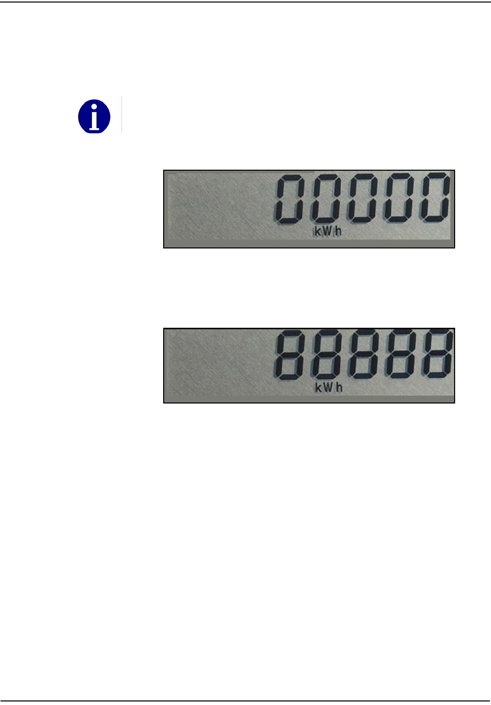
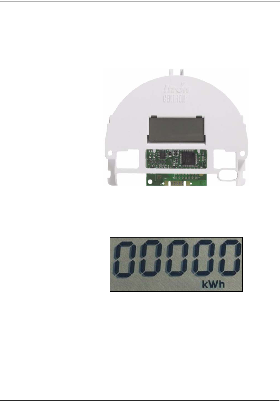
4.2 Mounted LCD Register . . . . . . . . . . . . . . . . . . . . . . . . . . . . . . . . . . . . . . . . . . . . . . . . . . . . . . . . . . . . . . . . . . 4-2
4.3 ZRO-C2A Resetter Connected to the CENTRON. . . . . . . . . . . . . . . . . . . . . . . . . . . . . . . . . . . . . . . . . . . . . . . 4-3
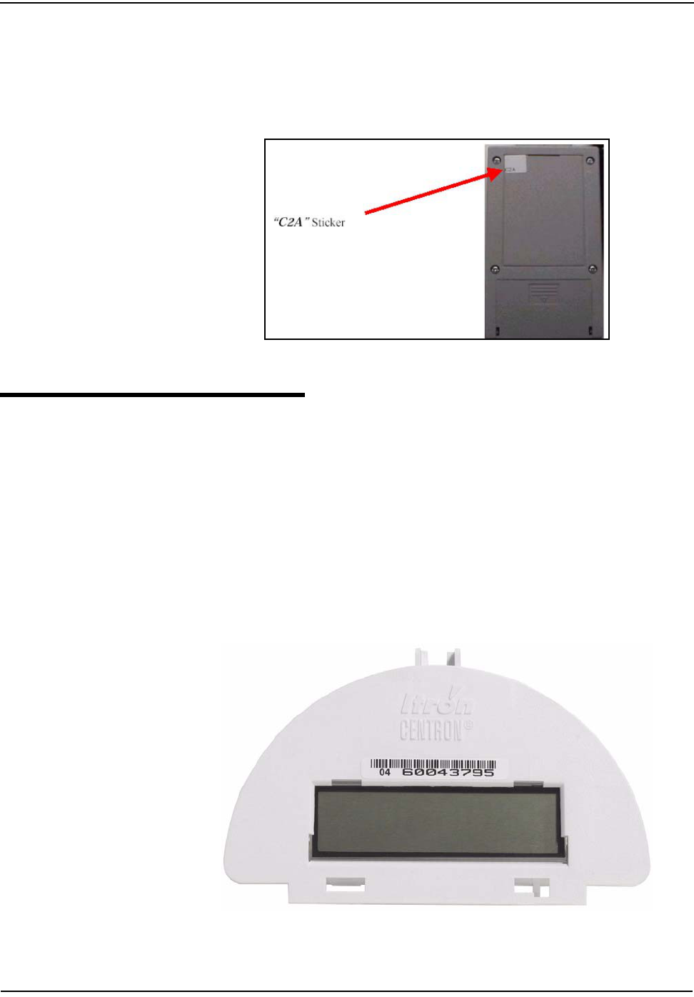
4.4 Reverse Side of ZRO Resetter. . . . . . . . . . . . . . . . . . . . . . . . . . . . . . . . . . . . . . . . . . . . . . . . . . . . . . . . . . . . . 4-4
4.5 Pre-June 2003 LCD . . . . . . . . . . . . . . . . . . . . . . . . . . . . . . . . . . . . . . . . . . . . . . . . . . . . . . . . . . . . . . . . . . . . . 4-4
4.6 LCD Display without Segment Check . . . . . . . . . . . . . . . . . . . . . . . . . . . . . . . . . . . . . . . . . . . . . . . . . . . . . . . 4-5
4.7 LCD Display with Segment Check. . . . . . . . . . . . . . . . . . . . . . . . . . . . . . . . . . . . . . . . . . . . . . . . . . . . . . . . . . 4-5
4.8 Post-June 2003 LCD . . . . . . . . . . . . . . . . . . . . . . . . . . . . . . . . . . . . . . . . . . . . . . . . . . . . . . . . . . . . . . . . . . . . 4-6
4.9 Non-Detented Register . . . . . . . . . . . . . . . . . . . . . . . . . . . . . . . . . . . . . . . . . . . . . . . . . . . . . . . . . . . . . . . . . . 4-6
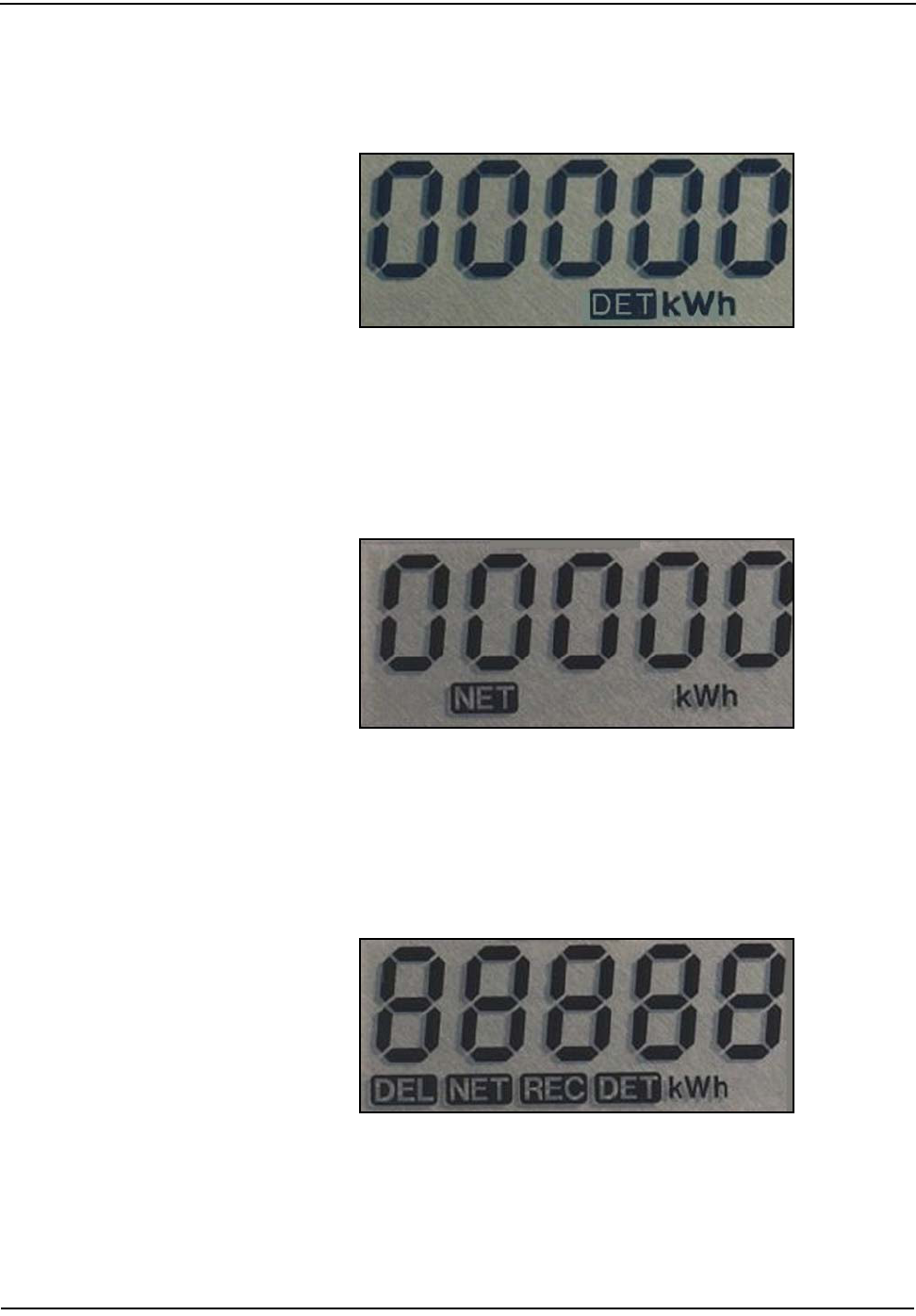
4.10 Delivered kWh with Detent Enabled. . . . . . . . . . . . . . . . . . . . . . . . . . . . . . . . . . . . . . . . . . . . . . . . . . . . . . . . 4-7
4.11 Net kWh . . . . . . . . . . . . . . . . . . . . . . . . . . . . . . . . . . . . . . . . . . . . . . . . . . . . . . . . . . . . . . . . . . . . . . . . . . . . . 4-7
4.12 Segment Test. . . . . . . . . . . . . . . . . . . . . . . . . . . . . . . . . . . . . . . . . . . . . . . . . . . . . . . . . . . . . . . . . . . . . . . . . . 4-7
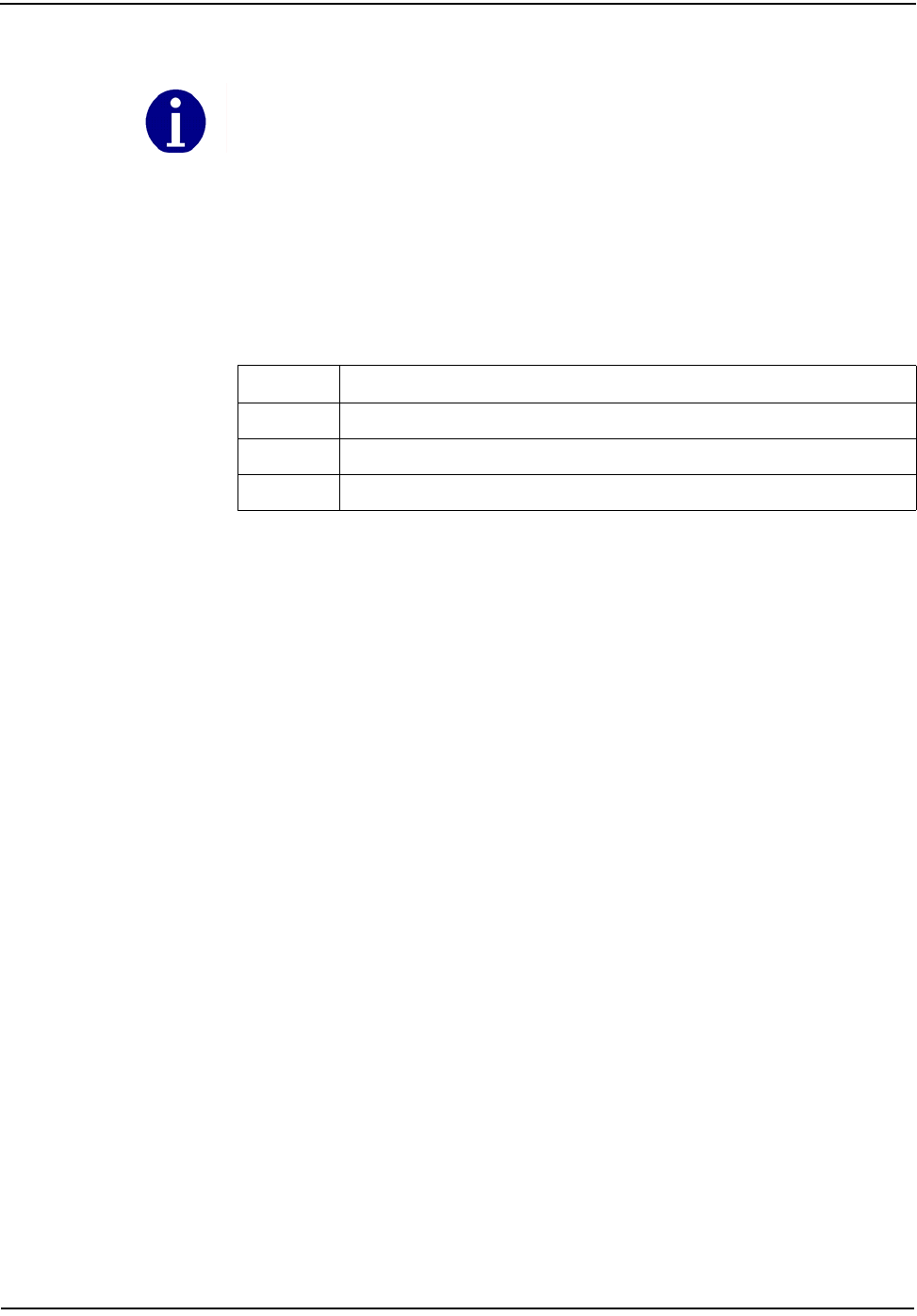
5.1 C1SL Meter with Cover. . . . . . . . . . . . . . . . . . . . . . . . . . . . . . . . . . . . . . . . . . . . . . . . . . . . . . . . . . . . . . . . . . 5-1
5.2 C1SL Controls . . . . . . . . . . . . . . . . . . . . . . . . . . . . . . . . . . . . . . . . . . . . . . . . . . . . . . . . . . . . . . . . . . . . . . . . . 5-2
5.3 Test Mode . . . . . . . . . . . . . . . . . . . . . . . . . . . . . . . . . . . . . . . . . . . . . . . . . . . . . . . . . . . . . . . . . . . . . . . . . . . . 5-4
5.4 Display. . . . . . . . . . . . . . . . . . . . . . . . . . . . . . . . . . . . . . . . . . . . . . . . . . . . . . . . . . . . . . . . . . . . . . . . . . . . . . . 5-5
5.5 Program File Export . . . . . . . . . . . . . . . . . . . . . . . . . . . . . . . . . . . . . . . . . . . . . . . . . . . . . . . . . . . . . . . . . . . . 5-13
5.6 Program File Export Type. . . . . . . . . . . . . . . . . . . . . . . . . . . . . . . . . . . . . . . . . . . . . . . . . . . . . . . . . . . . . . . . 5-14
5.7 Import Screen . . . . . . . . . . . . . . . . . . . . . . . . . . . . . . . . . . . . . . . . . . . . . . . . . . . . . . . . . . . . . . . . . . . . . . . . 5-14
5.8 CENTRON C1ST/L Battery Life . . . . . . . . . . . . . . . . . . . . . . . . . . . . . . . . . . . . . . . . . . . . . . . . . . . . . . . . . . . 5-24
5.9 Example 1 . . . . . . . . . . . . . . . . . . . . . . . . . . . . . . . . . . . . . . . . . . . . . . . . . . . . . . . . . . . . . . . . . . . . . . . . . . . 5-25
5.10 Example 2 . . . . . . . . . . . . . . . . . . . . . . . . . . . . . . . . . . . . . . . . . . . . . . . . . . . . . . . . . . . . . . . . . . . . . . . . . . . 5-25
5.11 Example 3 . . . . . . . . . . . . . . . . . . . . . . . . . . . . . . . . . . . . . . . . . . . . . . . . . . . . . . . . . . . . . . . . . . . . . . . . . . . 5-26
5.12 CENTRON TOU Personality Module with R300CD Option . . . . . . . . . . . . . . . . . . . . . . . . . . . . . . . . . . . . . . 5-28
6.1 C1SR . . . . . . . . . . . . . . . . . . . . . . . . . . . . . . . . . . . . . . . . . . . . . . . . . . . . . . . . . . . . . . . . . . . . . . . . . . . . . . . . 6-1
6.2 C1SR LCD. . . . . . . . . . . . . . . . . . . . . . . . . . . . . . . . . . . . . . . . . . . . . . . . . . . . . . . . . . . . . . . . . . . . . . . . . . . . . 6-2
6.3 CENTRON C1SR Transmission Cycle. . . . . . . . . . . . . . . . . . . . . . . . . . . . . . . . . . . . . . . . . . . . . . . . . . . . . . . . 6-4
6.4 C1SR FCC Label Location . . . . . . . . . . . . . . . . . . . . . . . . . . . . . . . . . . . . . . . . . . . . . . . . . . . . . . . . . . . . . . . . 6-6
7.1 C1SC . . . . . . . . . . . . . . . . . . . . . . . . . . . . . . . . . . . . . . . . . . . . . . . . . . . . . . . . . . . . . . . . . . . . . . . . . . . . . . . . 7-1
7.2 CellNet Telemetry . . . . . . . . . . . . . . . . . . . . . . . . . . . . . . . . . . . . . . . . . . . . . . . . . . . . . . . . . . . . . . . . . . . . . . 7-3
7.3 C1SC LCD. . . . . . . . . . . . . . . . . . . . . . . . . . . . . . . . . . . . . . . . . . . . . . . . . . . . . . . . . . . . . . . . . . . . . . . . . . . . . 7-4
7.4 C1SC/CN1SC Programming Port Location . . . . . . . . . . . . . . . . . . . . . . . . . . . . . . . . . . . . . . . . . . . . . . . . . . . 7-5
LIST OF FIGURES
Figure Figure Titles Page

List of Figures
xCENTRON Meter Technical Reference Guide
8.1 LED Location . . . . . . . . . . . . . . . . . . . . . . . . . . . . . . . . . . . . . . . . . . . . . . . . . . . . . . . . . . . . . . . . . . . . . . . . . . . 8-1
8.2 Pulse Detector . . . . . . . . . . . . . . . . . . . . . . . . . . . . . . . . . . . . . . . . . . . . . . . . . . . . . . . . . . . . . . . . . . . . . . . . . 8-2
8.3 TOU Rate Annunciators . . . . . . . . . . . . . . . . . . . . . . . . . . . . . . . . . . . . . . . . . . . . . . . . . . . . . . . . . . . . . . . . . . 8-3
9.1 Form 1S Wiring Diagram . . . . . . . . . . . . . . . . . . . . . . . . . . . . . . . . . . . . . . . . . . . . . . . . . . . . . . . . . . . . . . . . . 9-1
9.2 Form 2S Wiring Diagram . . . . . . . . . . . . . . . . . . . . . . . . . . . . . . . . . . . . . . . . . . . . . . . . . . . . . . . . . . . . . . . . . 9-2
9.3 Form 3S Wiring Diagram . . . . . . . . . . . . . . . . . . . . . . . . . . . . . . . . . . . . . . . . . . . . . . . . . . . . . . . . . . . . . . . . . 9-2
9.4 Form 4S Wiring Diagram . . . . . . . . . . . . . . . . . . . . . . . . . . . . . . . . . . . . . . . . . . . . . . . . . . . . . . . . . . . . . . . . . 9-3
9.5 Form 12S Wiring Diagram . . . . . . . . . . . . . . . . . . . . . . . . . . . . . . . . . . . . . . . . . . . . . . . . . . . . . . . . . . . . . . . . 9-3
9.6 Form 25S Wiring Diagram . . . . . . . . . . . . . . . . . . . . . . . . . . . . . . . . . . . . . . . . . . . . . . . . . . . . . . . . . . . . . . . . 9-4
Figure Figure Titles Page

CENTRON Meter Technical Reference Guide xi
1.1 Outer Cover Configurations . . . . . . . . . . . . . . . . . . . . . . . . . . . . . . . . . . . . . . . . . . . . . . . . . . . . . . . . . . . . . . . . . . . . . . . . 1-5
5.1 LCD Display Items . . . . . . . . . . . . . . . . . . . . . . . . . . . . . . . . . . . . . . . . . . . . . . . . . . . . . . . . . . . . . . . . . . . . . . . . . . . . . . . 5-6
5.2 Register Display Formats . . . . . . . . . . . . . . . . . . . . . . . . . . . . . . . . . . . . . . . . . . . . . . . . . . . . . . . . . . . . . . . . . . . . . . . . . . 5-8
5.3 Programmable Parameters. . . . . . . . . . . . . . . . . . . . . . . . . . . . . . . . . . . . . . . . . . . . . . . . . . . . . . . . . . . . . . . . . . . . . . . . . 5-9
5.4 Information Data Items . . . . . . . . . . . . . . . . . . . . . . . . . . . . . . . . . . . . . . . . . . . . . . . . . . . . . . . . . . . . . . . . . . . . . . . . . . 5-10
5.5 Test Mode Data Items . . . . . . . . . . . . . . . . . . . . . . . . . . . . . . . . . . . . . . . . . . . . . . . . . . . . . . . . . . . . . . . . . . . . . . . . . . . 5-12
5.6 Recording Duration for 32Kb . . . . . . . . . . . . . . . . . . . . . . . . . . . . . . . . . . . . . . . . . . . . . . . . . . . . . . . . . . . . . . . . . . . . . . 5-20
6.1 ReadOne Pro Tamper Count . . . . . . . . . . . . . . . . . . . . . . . . . . . . . . . . . . . . . . . . . . . . . . . . . . . . . . . . . . . . . . . . . . . . . . . . 6-6
8.1 AEP Test Codes. . . . . . . . . . . . . . . . . . . . . . . . . . . . . . . . . . . . . . . . . . . . . . . . . . . . . . . . . . . . . . . . . . . . . . . . . . . . . . . . . . 8-4
8.2 Error Codes. . . . . . . . . . . . . . . . . . . . . . . . . . . . . . . . . . . . . . . . . . . . . . . . . . . . . . . . . . . . . . . . . . . . . . . . . . . . . . . . . . . . . 8-5
8.3 Non-Fatal Error Codes . . . . . . . . . . . . . . . . . . . . . . . . . . . . . . . . . . . . . . . . . . . . . . . . . . . . . . . . . . . . . . . . . . . . . . . . . . . . 8-6
8.4 Fatal Error Codes . . . . . . . . . . . . . . . . . . . . . . . . . . . . . . . . . . . . . . . . . . . . . . . . . . . . . . . . . . . . . . . . . . . . . . . . . . . . . . . . 8-7
LIST OF TABLES
Table Table Titles Page

List of Tables
xii CENTRON Meter Technical Reference Guide
Notes:

CENTRON Meter Technical Reference Guide 1-1
Chapter 1 General Information
This technical reference guide explains the installation, operation, and
maintenance of the Itron CENTRON® meter family. Itron urges you to read the
entire manual before attempting installation, testing, operation, or maintenance of
a meter. To operate the Itron PC-PRO+® Programming Software and the
PRO-READ® handheld reader programmer discussed in this manual, refer to their
respective user manuals.
About This Manual
This manual contains the following information as listed in the chapter
descriptions below:
Chapter 1
General Information
Provides a general description, operation, physical and
functional descriptions, and complete meter specifications.
Chapter 2
Installation
Gives instructions for the proper handling and installation.
Chapter 3
Operation: Base
Describes the measurement technique used for the base on
the CENTRON meter.
Chapter 4
Operation: C1S
Provides a physical description and operational
characteristics of the basic watthour (kWh) only meter.
Chapter 5
Operation:C1SD, C1ST,
C1SL
Provides detailed information and theoretical operation for
Demand (C1SD), Time-of-Use (C1ST), and Load Profile
(C1SL) versions. Gives step-by-step procedures for
accessing the three operational modes and associated
displays.
Chapter 6
Operation: C1SR
Provides a physical description and the operational
characteristics of the R300 900 MHz radio frequency
personality module.
Chapter 7
Operation: C1SC
Provides a physical description and the operational
characteristics of the CellNet personality module.
Chapter 8
Testing, Troubleshooting,
and Maintenance
Provides an explanation of the testing, troubleshooting, and
maintenance of the CENTRON meter.
Chapter 9
Specification Numbers and
Drawings
Provides a reference to meter part numbers as well as
CENTRON wiring diagrams.
General Information
1-2 CENTRON Meter Technical Reference Guide
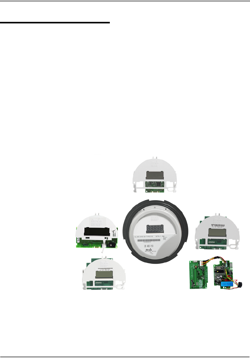
General Description
The CENTRON meter family is a solid-state, singlephase and network meter used
for measuring electrical energy consumption. The CENTRON incorporates a two-
piece design combining a base metrology with a variety of personality modules
that snap on the standard meter base. Utilizing the Hall Effect technology for
accurate power measurement, the metrology portion of the meter contains all
measurement circuitry and calibration information, while the personality modules
contain the register functionality and communication mediums.
Each version of the meter is distinguished by the various personality modules that
mount to the standard meter metrology base (see Figure 1.1) The personality
modules available include the following versions:
• Energy only—C1S (LCD)
• Demand—C1SD
• Time-of-Use (TOU) with Demand—C1ST
• Load Profile with TOU and Demand—C1SL
• Energy only with radio frequency AMR—C1SR
• CellNet Fixed Network—C1SC
• Energy plus demand with radio frequency AMR - R300CD
Figure 1.1 Personality Modules
General Information
CENTRON Meter Technical Reference Guide 1-3
Physical Description
The CENTRON meter features a common meter base to which various personality
modules are attached. The covers come in configurations of polycarbonate and
glass.
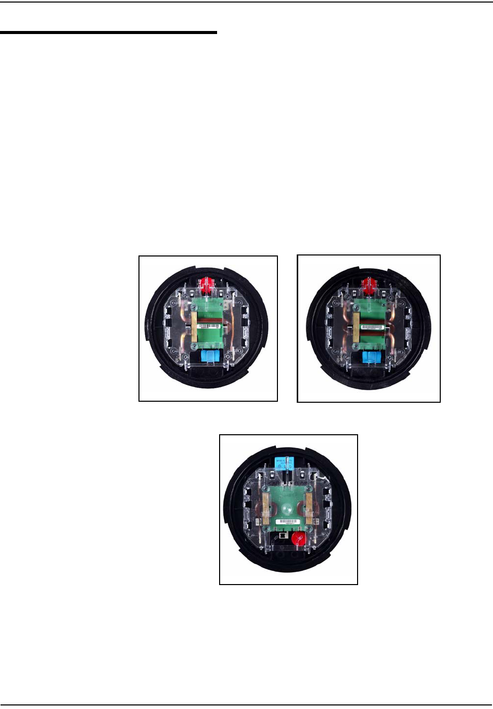
Meter Base
The CENTRON meter base contains all of the measurement circuitry and
calibration information on the metrology board.
The meter base assembly includes two current conductors, a flux-directing core, a
Hall Effect device, the metrology circuit board, and the ultrasonically welded
module support. The base also contains a MOV, metal oxide varistor, which is used
to protect the meter from line surges.
Meter bases are built specific to the metering form and are available in Form 1S, 2S
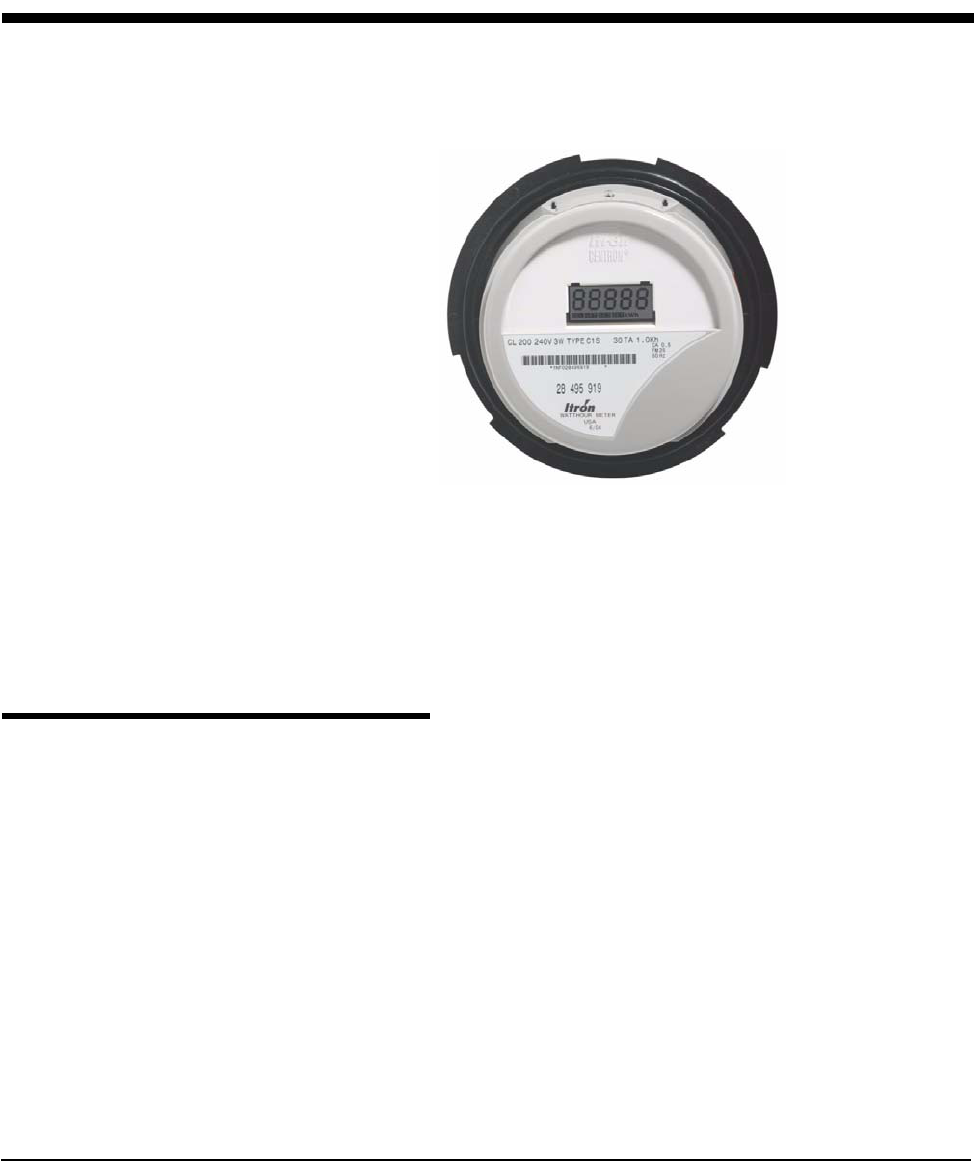
CL200, 2S CL320, 3S 120V, 3S 240V, 4S, and 12/25S configurations.Examples are
shown in Figure 1.2, Figure 1.3, and Figure 1.4.
Figure 1.2 Form 1S, 120 Volt Figure 1.3 Form 2S, CL200 240 Volt
Figure 1.4 Form 4S, 20 Amp Transformer-Rated
General Information
1-4 CENTRON Meter Technical Reference Guide
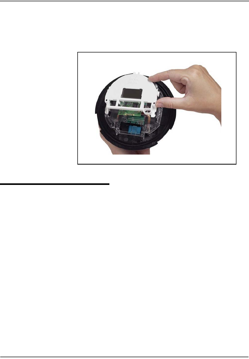
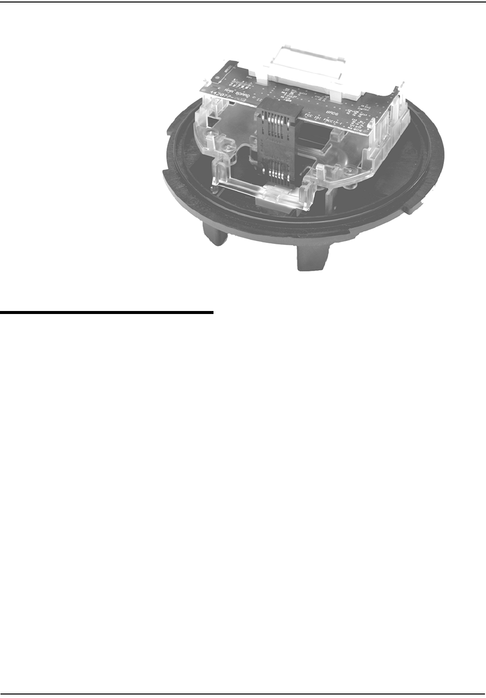
Personality Modules
All of the personality modules in the CENTRON meter family snap into the module
holder located on the standard meter base (see Figure 1.5). From the base
metrology, the energy data is transmitted to the personality modules, which
contain the meter display, communication mediums, and register functionality.
Figure 1.5 Personality Module Assembly
Product Availability
The current offerings for the CENTRON are:
Battery
The CENTRON C1ST and C1SL modules contain a battery that powers the clock
circuit during a power outage. The battery is permanently soldered to the module
and is expected to last the life of the module.
Refer to Chapter 5,"Operation: C1SD, C1ST, and C1SL Versions" for detailed battery
information.
Metrology Class 100, 120V, Form 1S
Class 200, 240V, Form 2S
Class 320, 240V, Form 2S
Class 20, 120V, Form 3S
Class 20, 240V, Form 3S
Class 20, 240V, Form 4S
Class 200, 120V, Form 12S
Class 200, 120V, Form 25S
Personality
Modules
C1S—LCD (5x1 or 4x10)
C1SR—R300C (Radio
Frequency)
C1SC—CellNet Data System
C1SD—Demand
C1ST—Time-of-Use (TOU)
C1SL—Load Profile
Option Boards R300CD

General Information
CENTRON Meter Technical Reference Guide 1-5
Covers
The outer cover configurations available for CENTRON meter family are described
in Table 1.1.
Outputs
The C1SD, C1ST, and C1SL personality modules are available input/output-ready
(I/O-ready). These modules contain circuitry that allows future functionality
expansion through I/O modules.
Display Functions
The C1S and C1SR modules can display kWh readings in either a 5x1 or 4x10
configuration.
The C1SD, C1ST, and C1SL modules can display a maximum of 32 Normal, 32
Alternate, and 8 Test display items, up to a total of 48 items.
Specifications
Electrical
Operating Environment
Table 1.1 Outer Cover Configurations
Meter Versions Cover Options
Polycarbonate Glass
C1S, C1SR, C1SC Standard Optional
C1SD, C1ST, C1SL Including Demand Reset+ Optical Tower Not Available
Voltage Rating 120V, 240V
Operating Voltage ± 20% (60 Hz); ± 10% (50 Hz)
Frequency 60 Hz, 50 Hz
Operating Range ± 3 Hz
Battery Voltage 3.6 V nominal (C1ST, C1SL only)
Operating Range 2.7V - 3.8V
Carryover 8 year cumulative and 15 year shelf life
Temperature -40°C to +85°C
Humidity 0% to 95% non-condensing
Accuracy ± 0.5% @ unity power factor
± 0.5% @ 50% power factor
Transient/Surge Suppression ANSI C37.90.1 - 1989
IEC 61000-4-4
ANSI C62.45 - 1992
General Information
1-6 CENTRON Meter Technical Reference Guide
Characteristic Data
Burden Data
To get the watt loss or VA of the overall product, add the metrology watt loss to the
register watt loss and option board watt loss.
Starting Watts
2S CL200 5W
1S, 2S CL320, 12S, 25S 10W
3S CL20 1.2W
4S CL20 2.4W
Temperature Rise Meets ANSI C12.1 Section 4.7.2.9
Metrology Voltage Watt Loss VA
1S 120 0.45 3.7
2S Class 200 240 0.45 7.2
2S Class 320 240 0.65 10.2
3S 240 0.65 10.2
4S 240 0.65 10.2
12S/25S 120 0.65 5.4
240V
Register LCD R300 CellNet D/T/L
Watt Loss 0.01 1.34 1.34 0.90
VA — 0.25 0.25 14.76
120V
Register LCD R300 CellNet D/T/L
Watt Loss 0.01 0.62 0.62 0.90
VA — 0.14 0.14 11.1
120V Option Board R300CD
Watt Loss 2.2
VA 23
240V Option Board
Watt Loss 2.2
VA 42
VA (Meter) VA (Metrology) VA (Register) + VA (Option Board)+=
Watt Loss (Meter) Watt Loss (Metrology) Watt Loss (Register) + Watt Loss (Option Board)+=
General Information
CENTRON Meter Technical Reference Guide 1-7
Technical Data
Meets applicable standards:
• ANSI C12.1-1995
• ANSI C12.10-1997
• ANSI C12.16 (Solid State Meters)
• ANSI C12.18 (Optical Communications Protocol)
• ANSI C12.20 (Class 0.5) - 1998
• IEC 61000-4-4
• IEC 61000-4-2
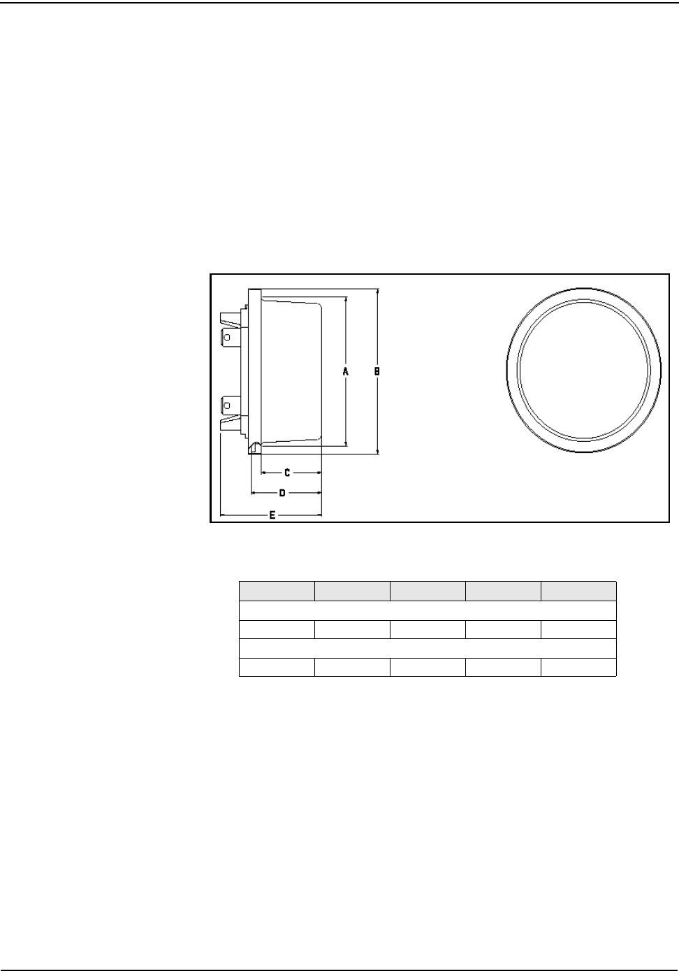
Dimensions
The following dimensional measurements are shown in inches and (centimeters).
Figure 1.6 Dimensions
ABCDE
Polycarbonate
6.29 (16.00) 6.95 (17.70) 2.70 (6.90) 3.16 (8.00) 4.53(11.50)
Glass
6.42 (16.30) 6.95(17.70) 3.17 (8.10) 3.64 (9.20) 5.01 (12.70)

General Information
1-8 CENTRON Meter Technical Reference Guide
C1SD/C1ST/C1SL Dimensions
The following dimensional measurements are shown in inches and (centimeters).
Figure 1.7 C1SD/C1ST/C1SL Dimensions
Shipping Weights
The following weight measurements are shown in pounds and (kilograms).
Polycarbonate
ABCDEFGH
6.95 (17.70) 6.29 (16.00) 2.70 (6.90) 3.16 (8.00) 4.53(11.50) 4.98(12.70) 6.29(16.00) 6.95 (17.70)
Polycarbonate Glass
Meter 1.375 (0.623) 2.75 (1.247)
4 Meters and Carton 8.90 (4.04) 13.96 (6.35)
96 Meter Pallets 214 (97.30) 335 (152.30)
CENTRON Meter Technical Reference Guide 2-1
Chapter 2 Installation
This chapter of the guide gives instructions for the proper handling and installation
of the CENTRON meter.
Inspection
Perform the following inspections when you receive the meter:
• Inspect for obvious damage to the cover, base, and meter assembly.
• Be sure the optical connector is free of debris.
• Compare the meter and register nameplates to the record card and invoice.
Verify the type, class, voltage, form number, and other pertinent data.
• Save the original packing materials.
Battery
The lithium battery is soldered to the register module circuit board (C1ST and
C1SL only). A low-power mode for the battery preserves the capacity of the
battery. Factory-programmed C1ST and C1SL meters should be put into service in
a timely manner to avoid degradation of the battery. Programmed meters are not in
low-power mode.
Storage
Store the meter in a clean, dry (Relative Humidity < 50%) environment between
-40° C to +85° C (-40° F to +185° F). Avoid prolonged storage (more than one year)
at temperatures above +70° C(+158° F). Store the meter in the original packing
material. The lithium battery has a shelf life of approximately fifteen (15) years.
The product you have purchased contains a recyclable lithium battery, circuit boards, and
switches. At the end of its useful life, under various state and local laws, it may be illegal
to dispose of this battery into the municipal waste stream. Check with your local area
solid waste officials for details about recycling options or proper disposal.
The C1SR also contains a tilt switch that may contain mercury. Please dispose of
properly.

Installation
2-2 CENTRON Meter Technical Reference Guide
Unpacking
As with all precision electronic instruments, the meter should be handled with care
in an outdoor environment. Follow these precautions when handling the meter:
• Avoid damaging the meter base, cover, reset mechanism (if supplied), and
optical connector (if supplied).
• When handling personality modules, grip the circuit board by its edges. Do not
touch the liquid crystal display.
Selecting a Site
The meter is designed and manufactured to be installed in an outdoor
environment, at operating temperature ranges between -40° C and +85° C (-40° F to
+185° F). Operation in moderate temperatures increases reliability and product
life.
When using a Demand, TOU, or Load Profile meter where the line frequency is not
stable, Itron recommends using either the C1ST or C1SL meter version with
Crystal Time synchronization if a clock is needed (TOU or Load Profile).
Installing the Meter into Service
Install the meter base using standard meter installation practices.
The current and potential terminals extend as blades, or bayonets, from the back
of the meter. The meter is plugged into the socket so that the bayonets engage the
main socket jaws that connect to the service lines. Clamping pressure on the
bayonets is provided by the heavy spring pressure of the socket jaws. In some
heavy-duty sockets, jaw clamping pressure is provided by a handle or wrench.
On meters equipped with LCD displays, verify register operations by observing the
display:
• LCD displays the correct number of digits (4 or 5).
• If the test mode annunciator is flashing, depress the Test mode button to
return the meter to the Normal mode (C1S D/T/L only).
• If the register only displays a Segment Test (all display items shown) and
flashes “CNTRON”, the register has not been programmed.
• Verify that no errors are displayed.
Installation
CENTRON Meter Technical Reference Guide 2-3
Programming the C1SD,T,L Meter
The personality module should be powered prior to programming. The module can
be programmed using the optical connector. The default communications rate
when programming through the optical tower is 4800 baud; 9600 baud is
selectable. Refer to PC-PRO+ documentation for detailed programming
information.
Retrofitting with Personality Modules
CENTRON meters can be upgraded to increase functionality by changing the
Personality Modules.
To change or add a Personality Module:
1 Remove power from the meter.
2 Remove the outer (polycarbonate or glass) cover.
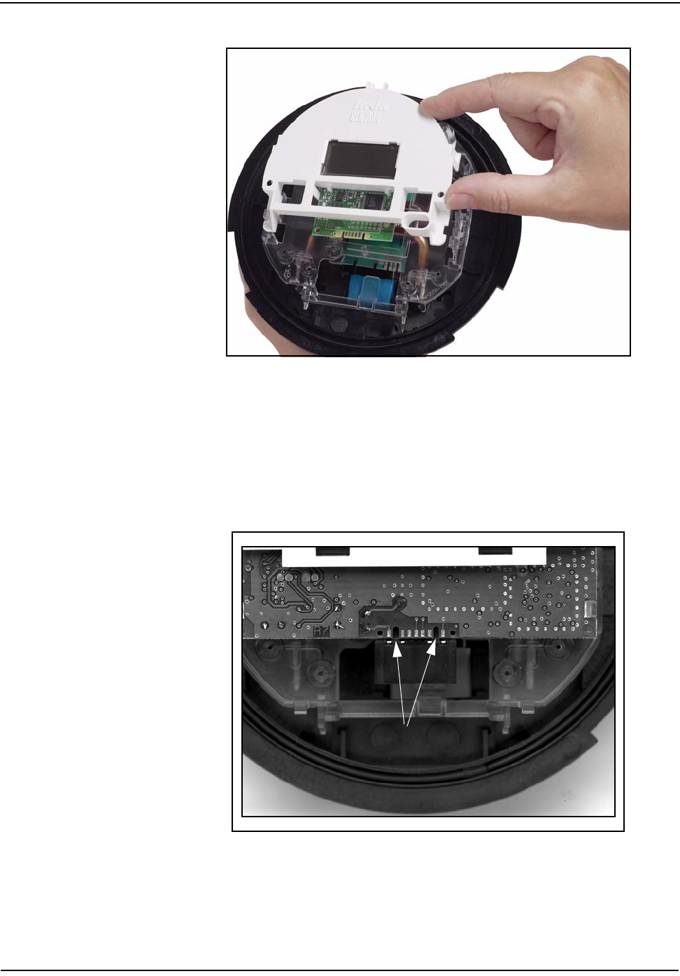
3 Remove plastic inner cover by holding the meter with both hands and applying
equal pressure on either side of the three and nine-o’clock positions. The inner
cover is held in place by four plastic tabs on the meter base.
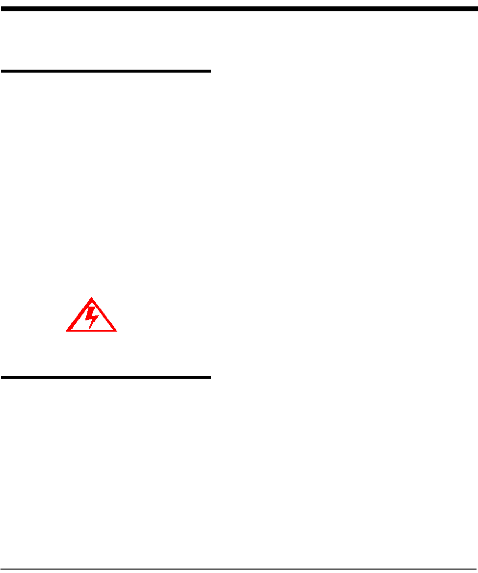
4 Remove the black board-to-board connector between the circuit board and the
metrology board by pulling it by its middle while moving it side-to-side (see
Figure 2.1). To maintain the integrity of the connector, only remove it when
you are upgrading the meter.
The practice of knowingly installing Form 12S/25S meters into metering sockets with
either missing or disconnected fifth terminal jaws in the meter socket is NOT
recommended for CENTRON Form 12S/25S meters.
The following guidance should be followed when using the Form 12S/25S CENTRON
meter:
• This version of the meter should not be used in a non-Form 12S or 25S metering
service.
• The meter's 5th terminal should be properly installed on the meter in a location
defined in the CENTRON Technical Reference Guide.
• The fifth terminal jaw in the meter socket should be properly connected to the
service neutral and installed in the correct location.
• The metering service should match the class, form and voltage rating on the meter's
nameplate.
Failure to follow these recommendations will result in damage to the CENTRON Form
12S/25S meter and void all product warranties.
Do not power ON the meter without the inner cover in place. Power the meter OFF before
removing the inner cover. Personality modules are sensitive to ESD damage. Take
appropriate grounding measures before retrofitting!
Installation
2-4 CENTRON Meter Technical Reference Guide
Figure 2.1 Removing the Board-to-Board Connector
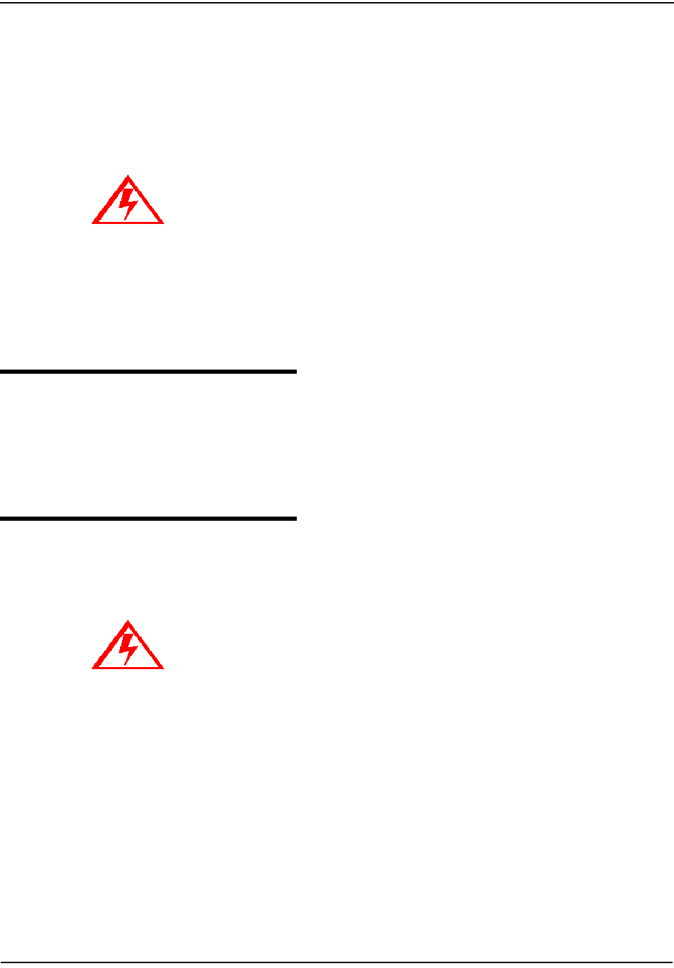
5 Remove the register module, one side at a time, by pulling gently outward on
the meter frame snaps (see Figure 2.2) while lifting the module up.
Figure 2.2 Removing the Register Module
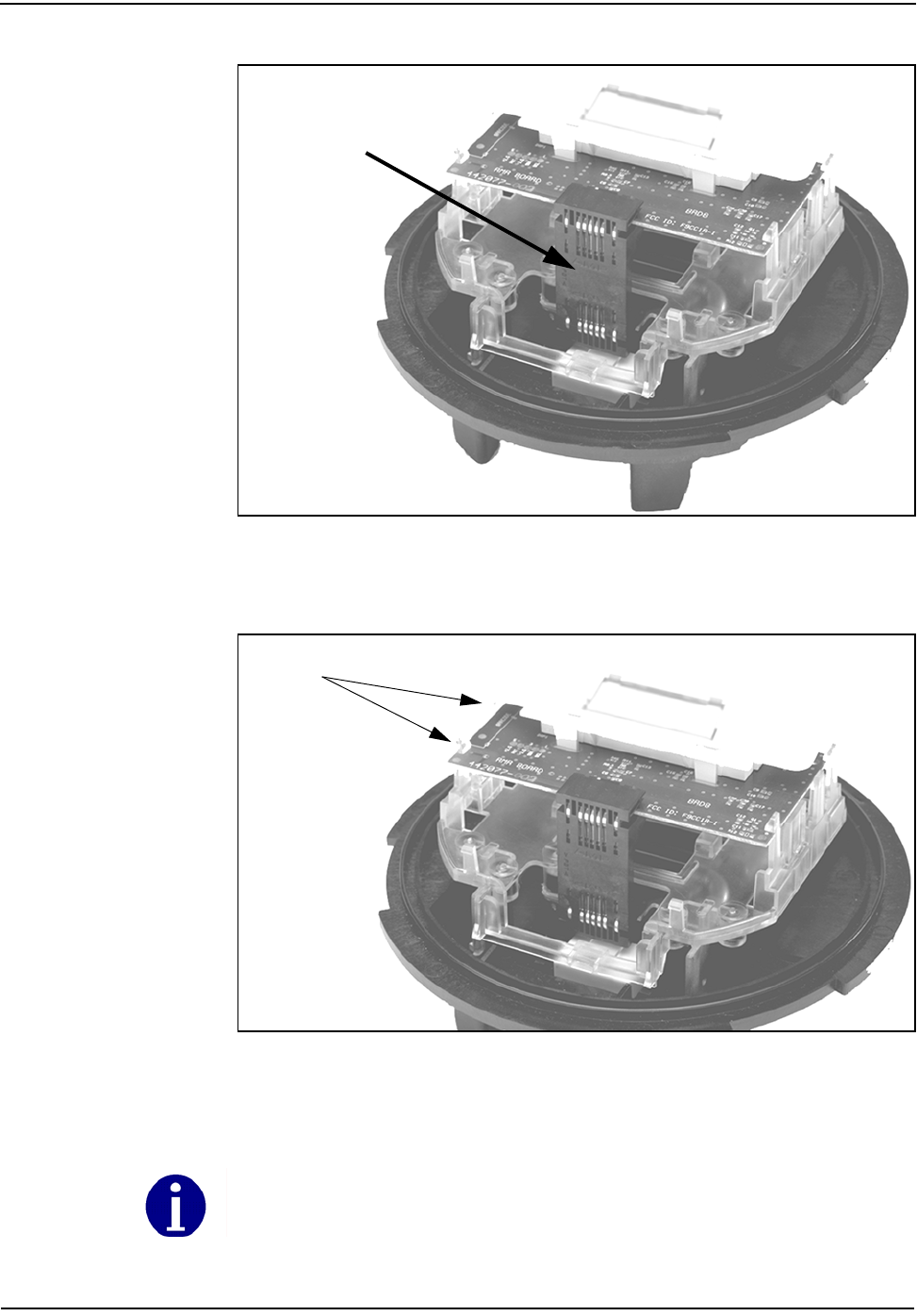
6 Snap the new module into the meter frame by aligning the notches at bottom
of the circuit board with the lower two snaps (see Figure 2.3).
Board-to-Board
Connector
Meter Frame
Snaps
The module must be aligned properly in the snaps to avoid damaging the connector or circuit
board.
Installation
CENTRON Meter Technical Reference Guide 2-5
Figure 2.3 New Module Snap-in
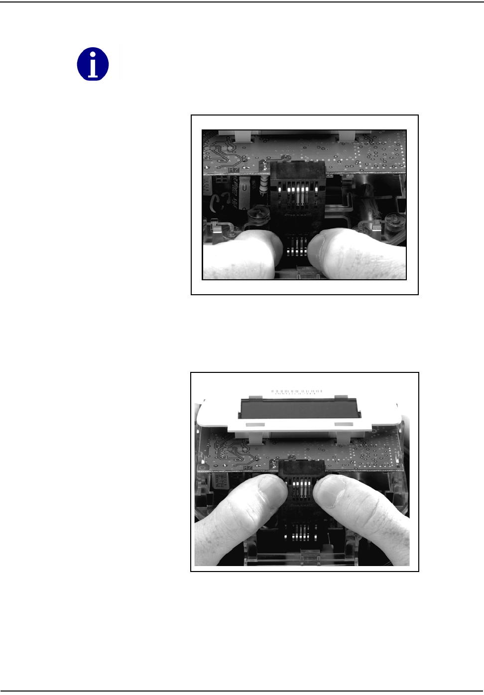
7 Replace the board-to-board connector by aligning the top of the connector
with the notches in the circuit board (see Figure 2.4) and pressing gently at the
bottom of connector to mate the connector to metrology board (see Figure
2.5). Then, gently press the top of the connector to mate it to the register
module (see Figure 2.6). The connector is seated correctly when you hear it
snap into place.
Figure 2.4 Circuit Board Notches
Notches (2)
Installation
2-6 CENTRON Meter Technical Reference Guide
Figure 2.5 Board-to-Board Connector, Bottom
8 Ensure the board-to-board connector is fully seated by pressing firmly in on
the middle of the connector.
Figure 2.6 Board-to-Board Connector, Top
9 Carefully replace the inner protective cover. Engage the top snaps first, taking
care to place the slot at the top of the cover over the IR light pipe. Failure to do
so could break the light pipe. Ensure that all four meter base tabs are engaged
with the slots at the top and bottom of the inner cover.
Be sure to use the meter base for leverage instead of the LCD holder (see Figure 2.5). Pressure
on the LCD holder may damage the personality module.

Installation
CENTRON Meter Technical Reference Guide 2-7
10 Place the cover over the meter base until the flange on the cover is flush with
the flange on the meter base.
11 Turn the cover clockwise until the locking tabs are fully engaged with the
meter base.
12 If the cover has a Demand Reset or an Optical Connector, be sure these are
properly aligned with their corresponding accessory on the register faceplate.
If not aligned correctly, the Demand Reset or Optical Connector will not
function properly. If the Demand Reset plunger is not in the retracted position
before turning the outer cover, the mechanism may be damaged.

Notes:
2-8 CENTRON Meter Technical Reference Guide
Installation

CENTRON Meter Technical Reference Guide 3-1
Chapter 3 Operation: Base Metrology
This chapter describes the measurement technique used for the base metrology on
the CENTRON meters.
CENTRON 1S, 2S CL200, and 3S
The CENTRON meter is a solid-state meter which uses the inherent multiplication
properties of the Hall Effect to measure power. The Hall Effect principle relies on a
physical property: a conductor which carries a current in a magnetic field
generates a voltage difference across the conductor proportional to the product of
the current and the magnetic field.
The voltage Vout created at the output of the Hall device:
Where
ib is the biasing current (derived from the line voltage)
B is the magnetic field density (derived from the line current)
K is the Hall coefficient (analogous to a gain factor in any meter)
K could be viewed as the Hall sensor intrinsic gain and is maximized by the
appropriate choice of semiconductor materials that have been uniquely optimized
by Itron for the CENTRON meter.
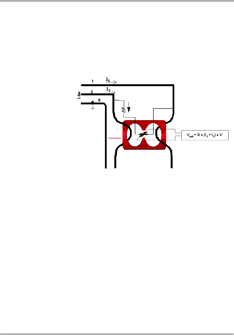
For the metering application, the biasing current ib applied to the sensor is
generated from the line voltage (V) using a resistor (R).
The magnetic field (B) is generated by the line currents (I = I1 + I2) that flow
through two conductors looped around the core.
Where
C is a constant that is dependent upon the geometric and magnetic properties
of the coil
This field is focused to flow through the Magnetic Core's air gap where the Hall
sensor is precisely positioned. The voltage, Vout, which is formed on the Hall
Effect device is proportional to the input watts (see Figure 3.1).
Vout KibB×=
ibVR⁄=
BCI×CI
1I2
+()×==
Operation: Base Metrology
3-2 CENTRON Meter Technical Reference Guide
The output voltage of the Hall Effect device is then:
G is the combined gain factor of the entire system (Voltage to biasing current, line
Current to flux density, Hall sensor).
Figure 3.1 Power Measurement Principle in 2S
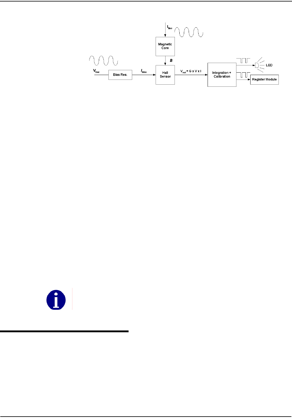
From the power information available at the output voltage of the sensor, the
meter architecture is simplified over previous designs as the multiplication has
already taken place (see Figure 3.2).
The Hall sensor output voltage is amplified by a differential amplifier in order to
bring the signal within the nominal level of the analog to digital converter (ADC).
The output of the ADC is integrated over time to get the energy information and
generates a pulse stream that is accumulated into a counter. When the
accumulated pulses reach a threshold set by meter calibration, a Wh pulse is
emitted and the meter LED is flashed. The counter threshold is programmed at the
factory and serves as the permanent gain calibration for the life of the product. The
calibration is a digital feature and has no variation or adjustment. All the
processing steps described above are integrated into an Application Specific
Integrated Circuit (ASIC) to improve reliability and reduce cost.
Vhall V= out GIV GPower==
Where G C R⁄()K=
ib
Operation: Base Metrology
CENTRON Meter Technical Reference Guide 3-3
Figure 3.2 Simplified CENTRON Architecture
The custom ASIC cancels all the offset generated by the meter and removes the
need for a light load adjustment of the metrology. This allows the meter to have
excellent accuracy over a very large dynamic range, especially at the low current
levels. For this reason, no offset adjustment is needed or provided for the
CENTRON meter.
There is a slight phase shift in the current to flux density conversion due to eddy
currents in the magnetic core material. This shift causes a small power factor error
that is uniform across the dynamic range (load curve) of the meter. Itron
compensates for this shift in the CENTRON by the use of a capacitor in the biasing
current circuit. This correction is permanent.
The custom ASIC provides:
• Wh pulses to drive the Test LED
The same signal is also provided to the electronic register attachments.
• energy direction (sign)
• 60Hz clock signal synchronized with the line voltage (for time keeping)
• pulse that drives the stepper motor for the mechanical register attachment (1
pulse every 10 watthours)
The metrology board, which houses the measurement components described
above, passes the Wh pulse, energy direction, and 60Hz clock signals to the
personality module attached to the meter base. The two line voltages (one is
referred to as meter ground), and power supply references are also supplied for
reference purposes.
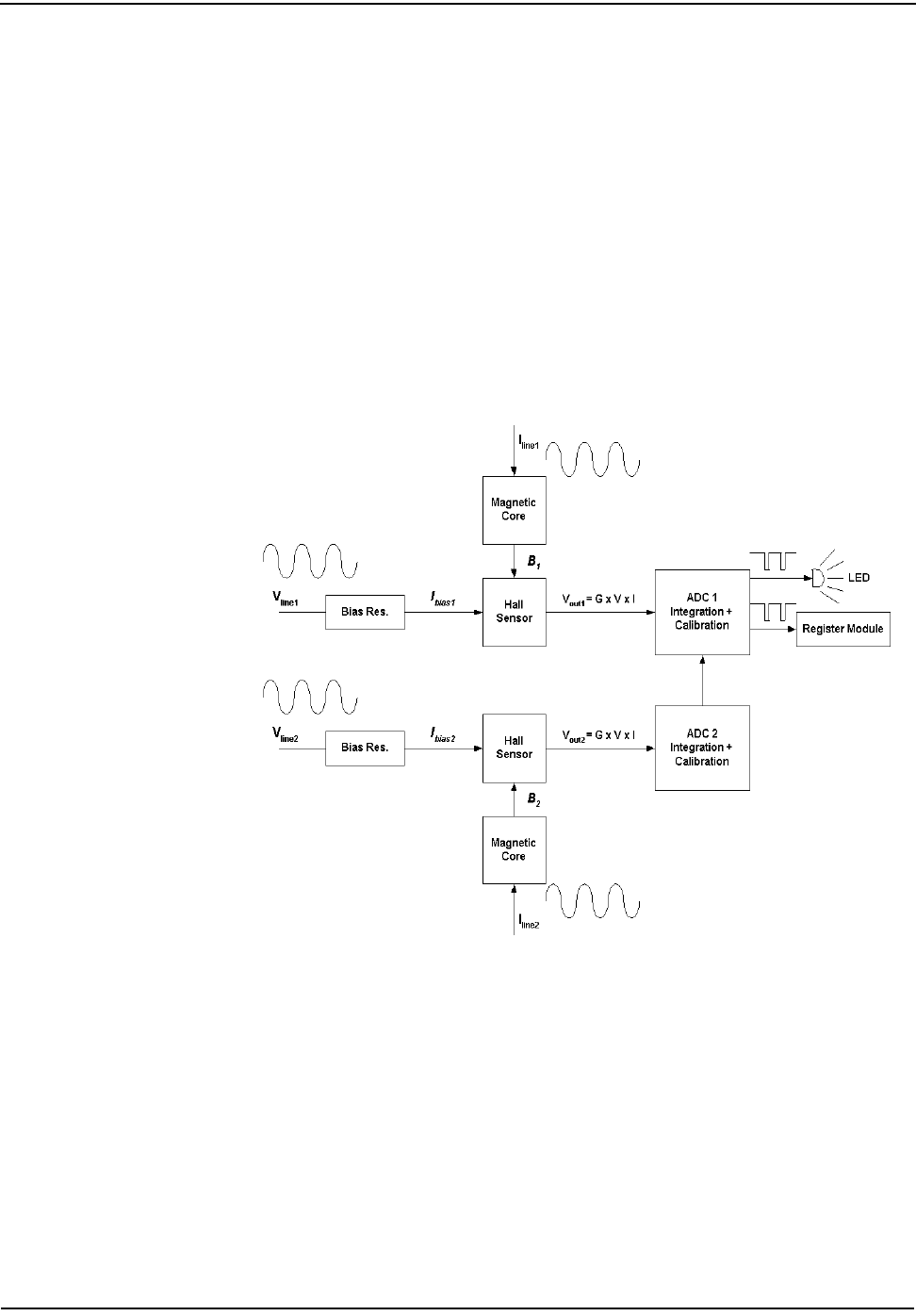
CENTRON 2S CL320, 4S, 12/25S
The advanced metering forms of the CENTRON (2S CL320, 4S, and 12/25S) meter
use the same Hall Effect measurement principle that is used in the form 1S, 2S, and
3S metering forms described earlier in this chapter.
The major difference with these metering forms is the presence of two Hall cells,
magnetic cores, and ADCs (see Figure 3.3).
An inherent feature built into the design of each CENTRON ensures that the calibration of the
product is not affected by any electronic board (existing or planned) added to the meter. This is
achieved by a distributed power supply and documented design requirements in the CENTRON
developer’s kit.
Operation: Base Metrology
3-4 CENTRON Meter Technical Reference Guide
For these metering applications, the biasing current Ibias (Ibias1 and Ibias2) applied to
each sensor is generated from the line voltage (Vline1 and Vline2) using a resistor. The
magnetic field is generated by the line current (Iline1 and Iline2) that flows through the
conductor looped around each core. The voltage (Vout1 and Vout2) that is formed on
each Hall Effect device is proportional to the watts produced by each phase.
Each Hall sensor output voltage is amplified by a differential amplifier in order to
bring the signal within the nominal level of the ADC. ADC 1 sums the signal from
ADC 1 and ADC 2. The output of ADC 1 is integrated over time to get the energy
information. Each time the integrated signal exceeds a predetermined amount of
energy, a pulse is generated. The pulse stream is accumulated into a counter. When
the accumulated pulses reach a threshold, a Wh pulse is emitted and the meter
LED is flashed. The counter threshold is programmed at the factory and serves as
the permanent gain calibration for the life of the product. The calibration is a
digital feature and has no variation or adjustment. ADCs 1 and 2 are calibrated
independently, which means that each phase is calibrated independently.
Figure 3.3 Hall Cells and ADCs
CENTRON Meter Technical Reference Guide 4-1
Chapter 4 Operation: C1S Version
The kWh only version of the CENTRON meter is available with an LCD personality
module to register energy accumulation.
Figure 4.1 C1S LCD Personality Module
The LCD module may be ordered with a 5x1 or 4x10 register for self-contained
meters, and a 5xTR or 4xTR register for transformer-rated meters.
The kWh only version of the CENTRON not only provides very accurate
measurement for energy accumulation for today's needs, but also provides a
platform for easy upgrade to higher functionality in the future.
Physical Description
The CENTRON Personality Modules snap into the meter register mounting
brackets to ease installation of the board.
The LCD module is connected to the metrology board using the board-to-board
connector. The following information is sent to the LCD module from the
metrology board:
• Line voltage
• Reference voltage
• Energy flow direction
• Energy pulse data
• Line frequency
A connector is located at the 12 o'clock position behind the LCD for resetting the
energy register. This is done using the ZRO-C2A Resetter.
Operation: C1S Version
4-2 CENTRON Meter Technical Reference Guide
Figure 4.2 Mounted LCD Register
Registers
Kilowatt Hours
The modules display energy in increments of whole values of kWh. Standard
operation for all modules is to add forward and reverse energy flow. Therefore, if
the meter is inverted, the registers will accumulate in the forward direction, thus
providing uni-directional operation. At the time of order, the LCD module can be
selected to have a detent register. Programmed at the factory, this feature will
cease registration while the meter is inverted, or power flow is otherwise reversed.
The module can also be selected to have a net register. This feature is factory
programmable and will subtract registration while the meter is inverted, or power
flow is otherwise reversed.
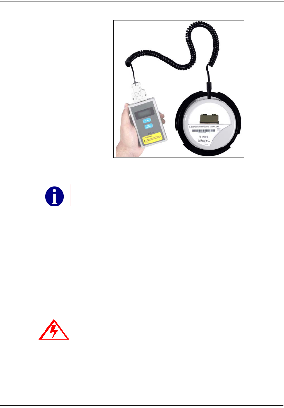
Resetting Values
The ZRO-C2A (see Figure 4.3) resets the energy register through a direct
connection to the connector at the 12 o'clock position on the LCD and R300
modules.
Operation: C1S Version
CENTRON Meter Technical Reference Guide 4-3
Figure 4.3 ZRO-C2A Resetter Connected to the CENTRON
The ZRO-C2A is a pocket-sized handheld device for resetting the electronic meter
readings in the CENTRON LCD kWh meter (C1S) and the R300 meter (C1SR). The
ZRO-C2A also resets the tamper indicators in the C1SR.
The ZRO-C2A requires that the meter Not Be Powered. The device connects to
the CENTRON meter through a hole in the plastic inner cover located at the 12
o’clock position on the meter (see Figure 4.3). Extending from the ZRO-C2A is a
cable terminating in a connector which mates to the programming connector of
the CENTRON.
Beginning February 20, 2002, the C1SR module for the CENTRON meter uses a
new EEPROM component. This new EEPROM operates at a different voltage level
requiring revision to the CENTRON resetter.
The ZRO-C2A Resetter works with both pre-June 2003 and Post-June 2003 LCDs.
Use of a ZRO-C or ZRO-C2 resetter without the C2A upgrade WILL CAUSE DAMAGE to
the personality modules on both the C1S LCD and C1SR meters produced after the new
EEPROM implementation date; damaged modules will show “Error” on the display.
Operation: C1S Version
4-4 CENTRON Meter Technical Reference Guide
All current production resetters and resetters produced after June of 2001 were
built with the C2A upgrade and are labeled accordingly as shown in Figure 4.4
below. Although personality modules with the new EEPROM are only compatible
with the C2A version of the CENTRON resetter (ZRO-C2A), the older revisions of
the personality modules are also compatible with the ZRO-C2A.
Figure 4.4 Reverse Side of ZRO Resetter
LCD Display Function
The CENTRON LCD has been updated as of June 2003. All CENTRON C1S meters
built after this date will incorporate the new LCD. The following sections describe
both the new LCD and the old LCD. The information on the pre-June 2003 LCD is
provided for users who purchased meters prior to the change. This display is no
longer available for order.
Pre-June 2003 LCDs
The pre-June 2003 LCD module is shown in Figure 4.5. Two separate versions of
the LCD are available. Both versions may be configured for either four or five digits
and will roll over at 100,000 kWh. The LCD is automatically adjusted for contrast
over the operating temperature range.
Figure 4.5 Pre-June 2003 LCD
Operation: C1S Version
CENTRON Meter Technical Reference Guide 4-5
The non-segment check version displays only the kWh reading. A downward
pointing arrow on the LCD pulses at a rate equal to the energy consumption. The
arrow flashes on for 1 watthour and off for 1 watthour. This effectively produces
an equivalent Kh of 2.0.
Figure 4.6 LCD Display without Segment Check
A second version of the LCD is available which displays the kWh reading and a
segment check (see Figure 4.7). The display scrolls between the kWh reading and
segment check with 7 seconds of on-time for each display item.
Figure 4.7 LCD Display with Segment Check
The three triangle segments in the bottom right corner of the display represent a
watt disk emulator. This electronic load indicator will advance with each pulse,
since each pulse is equivalent to one watthour. Reverse power is indicated by a
reversal in the direction of the electronic load indicator.
Infrared LED Kh is 1.0.
Operation: C1S Version
4-6 CENTRON Meter Technical Reference Guide
Post-June 2003 LCDs
The post-June 2003 LCD module is shown in Figure 4.8. This display uses five
7-segment digits, four icons to indicate the type of displayed data, and three icons
to represent a watt disk emulator. The display may be configured for either four or
five digits and will roll over at 100,000 kWh.
This module is compatible with the ZRO-C2A Resetter.
Figure 4.8 Post-June 2003 LCD
Non-Detented Register
The Non-Detented Register displays the delivered energy plus received energy.
Figure 4.9 Non-Detented Register
Operation: C1S Version
CENTRON Meter Technical Reference Guide 4-7
Detented Register
The Detented Register addresses applications requiring the reading of delivered
kWh only. Received energy is discarded.
Figure 4.10 Delivered kWh with Detent Enabled
Net Register
The Net (kWh) Register addresses applications requiring residential net metering
points. Net kWh is the delivered kWh to the customer minus any received kWh
from the customer. Net metering emulates a non-detented J5 meter.
Figure 4.11 Net kWh
Segment Check
The Segment Check Register addresses applications requiring display scrolling
between kWh and a full segment check. See "Display Timing" on page 4-8 for
factory programming options.
Figure 4.12 Segment Test
Operation: C1S Version
4-8 CENTRON Meter Technical Reference Guide
Factory Programming Options
Display Timing
The display will scroll between the billing register and the segment check mode
based on the factory programming option.
Digits and Multipliers
The following digit and multiplier settings are available for factory programming:
• 4 digits x 1 kWh
• 4 digits x 10 kWh
• 5 digits x 1 kWh
Although the DEL and REC indicators are ON during segment check, they are not currently used.
Option Description
1 7 second billing register display, 1 second blank, 7 second segment check display (7/7)
2 7 second billing register display, 1 second blank, 1 second segment check display (7/1)
3 Only the billing register is displayed (7/0)
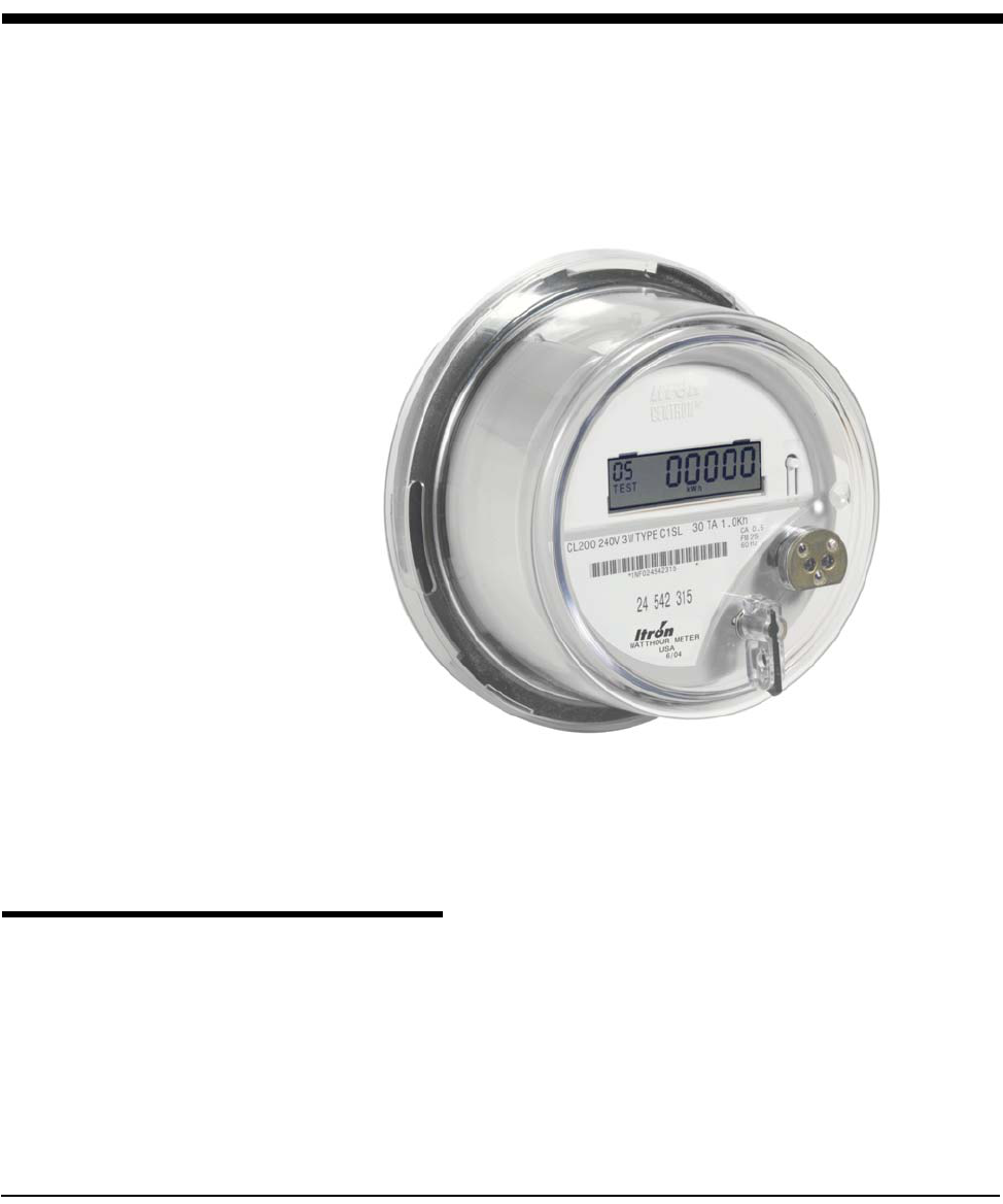
CENTRON Meter Technical Reference Guide 5-1
Chapter 5 Operation: C1SD, C1ST, and C1SL Versions
The CENTRON meter is available with interchangeable personality modules that
snap-into the standard CENTRON metrology base. The three multifunction
modules available include the following versions:
• C1SD—a demand module
• C1ST—a Time-of-Use (TOU) module with demand
• C1SL—a load profile module with TOU and demand
Figure 5.1 C1SL Meter with Cover
These personality modules utilize the SCS protocol which allows the C1SD, C1ST,
and C1SL meters to mimic the Itron 200 Register Series product line for use with
existing systems.
Features
Features of these multifunction modules include:
•Non-Volatile Memory—Programming, register, and load profile data are
stored in the EEPROM during a power outage. The TOU and load profile
modules contain a battery that maintains the clock circuitry during a power
outage.
•Optical Port Communication—Each module can be programmed to
communicate 9600 or 4800 baud through the optical tower.
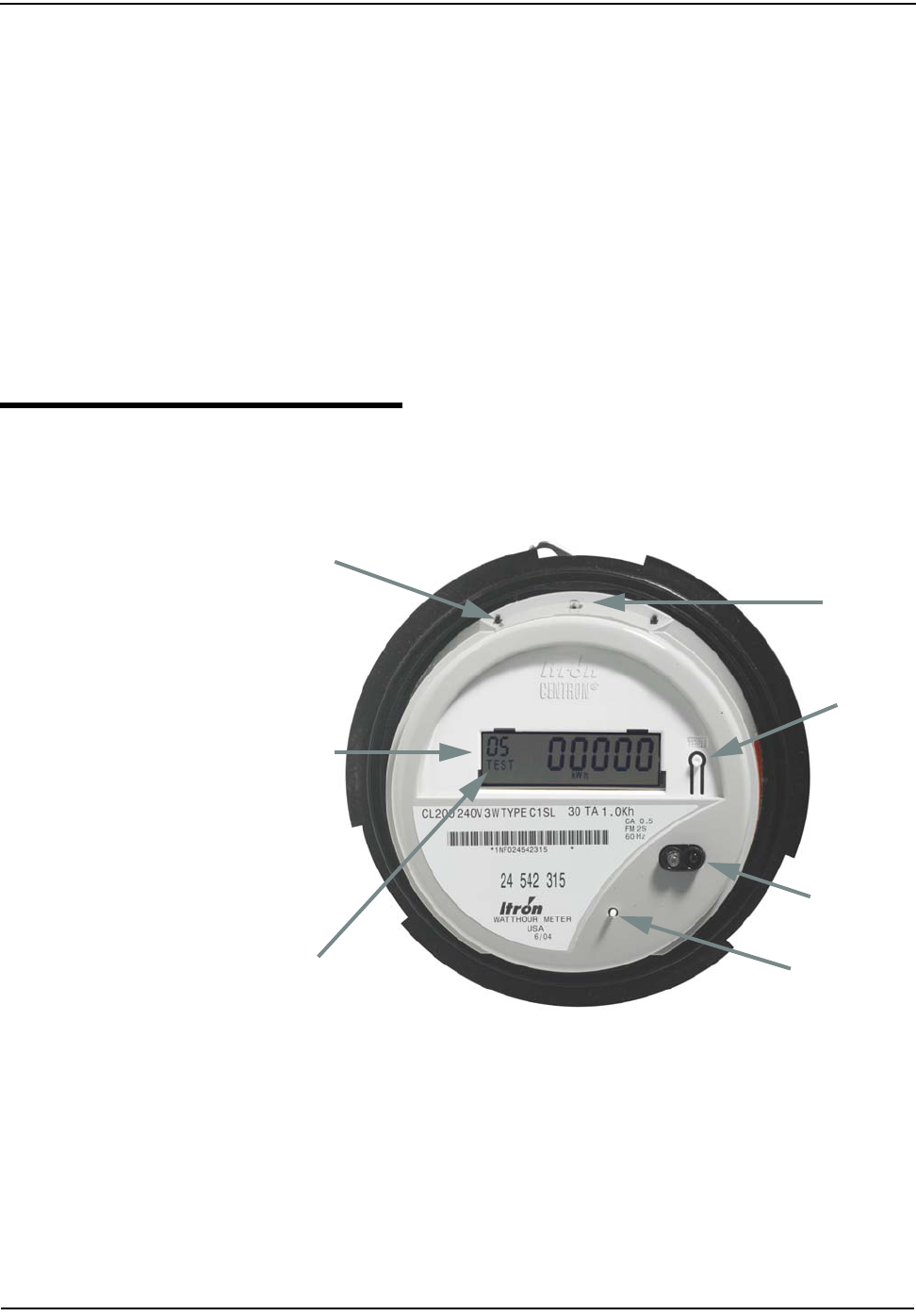
Operation: C1SD, C1ST, and C1SL Versions
5-2 CENTRON Meter Technical Reference Guide
•Self-Read Capability—Billing data can be stored automatically at
programmable times to be read later.
•Load Profile—The C1SL module provides 32K RAM for load profile data.
•Expansion Capability—An expansion port is available for future functions.
•Bidirectional Metering—All three multifunction versions are capable of
measuring and displaying forward and reverse energy only (kWh). These
modules have two separate registers; one for forward kWh and one for reverse
kWh. When the meter is programmed with electronic detent, both the forward
kWh register and the reverse kWh register will be utilized. When the meter is
programmed to be undetented, the forward and reverse energy will
accumulate in the forward kWh register.
The C1SD, C1ST, C1SL modules are available with an LCD display and a
polycarbonate cover. The cover contains the optical port adapter and demand
reset button.
Controls and Indicators
All controls and indicators are shown in Figure 5.2. For detailed instructions about
a feature or control, refer to the appropriate subsection.
Figure 5.2 C1SL Controls
LCD Display
Demand Reset
Test LED
Optical Tower
Annunciators
Magnetic Reed
Test Mode
Switch
Switch

Operation: C1SD, C1ST, and C1SL Versions
CENTRON Meter Technical Reference Guide 5-3
Modes of Operations
When the C1SD, C1ST, and C1SL modules are powered, they automatically enter
the normal display mode, perform self-diagnostics and display any appropriate
error codes. If no error codes are detected, an unprogrammed module will
alternate between CNTRON and Segment Test. A programmed module will
scroll through the Normal display sequence, displaying each selected quantity,
annunciator, and code number for the programmed duration.
The C1SD, C1ST, and C1SL modules each have three modes of operation:
•Normal
•Alternate
•Test
Normal Mode
In Normal mode, the module display automatically sequences through the
programmed displays and annunciators in the programmed sequence. Each
parameter is displayed for the program-specified period (from 1 to 15 seconds),
followed by a blank display for one second. Only the annunciator appropriate to
the selected module display can appear while its data is displayed. Each display
can have a two-digit identifier. If selected, this code can be programmed to be any
number from 00 to 99.
Calculations are performed to obtain programmed quantities. Specific details of
the calculated values are covered under Programmable Functions in this section.
The meter will continue to operate in Normal mode until power is disconnected,
the Alternate display sequence is initiated, Test mode is selected, or an error
condition occurs.
Alternate Mode
The Alternate mode provides an additional set of customizable display items that
are not typically used for billing applications. The Alternate mode is accessible
only from the Normal mode and is activated using either the magnetic reed switch
or a meter programming device. To activate the Alternate mode using the magnetic
reed switch, move a small magnet (approximately 30 gauss) near the reed switch
located at the 10 o'clock position on the side of the module (see Figure 5.2). The
magnetic reed switch can be accessed with the meter cover in place. To activate
the Alternate mode with a programming device, refer to the PC-PRO+
documentation. Immediately upon activation, Alternate mode is indicated by a
flashing ALT annunciator. The ALT annunciator will not appear if there are no
Alternate mode display items programmed.
Once the Alternate mode has been selected, the display will sequence once
through the alternate program items and return to the Normal display sequence.
The quantities displayed are selected during programming and have the same
display timing as in Normal mode. Like the displays in Normal mode, each display
in Alternate mode can have a two-digit identifier, programmable from 00 to 99. The
calculations and operations performed in Alternate mode are identical to those in
Normal mode.
Test Mode
Selecting the Test mode causes the current interval demand to be compared to the
stored maximum demand and the current billing data to be transferred to non-
volatile memory. If the current interval demand value is greater than the maximum
demand, the current interval demand becomes the maximum demand. All Test
Operation: C1SD, C1ST, and C1SL Versions
5-4 CENTRON Meter Technical Reference Guide
mode program parameters are then retrieved from nonvolatile memory for use in
the Test mode. In the C1SL version, a status bit is set to indicate the register was
placed in Test mode.
The Test mode can be activated while in either Normal or Alternate mode using the
Test mode switch (see Figure 5.3) or a meter programming device. To activate the
Test mode with a programming device, refer to the PC-PRO+ documentation.
Immediately upon activation, the Test mode is indicated by a flashing “TEST”
annunciator in the lower left hand corner of the module display. The TEST
annunciator will not appear if there are no Alternate mode display items
programmed.
Figure 5.3 Test Mode
Refer to the PC-PRO+ documentation for information on selecting the Test mode
using a programming device. A programmable “Time-Out Length” from 1-to-99
minutes is available. After the programmed Time-Out Length has ended, the
register will automatically exit the Test mode. The demand test interval is
initialized whenever the Demand Reset button is pressed.
The magnetic reed switch, when activated, advances the Test mode display to the
next quantity. Calculations performed in Test mode are performed in the same
manner and based on the same program parameters as in Normal mode with the
exception of interval (subinterval) length. Test mode interval length and the
number of subintervals are specified independently for Test mode. The results are
displayed according to the display configuration selected when the register is
programmed. To exit the Test mode and return to the Normal mode, do one of the
following:
• De-energize the meter.
• Push the Test mode button.
• Wait for the selected Test mode time-out to occur.
Calculated values performed in Test mode are not added to previous billing values
or stored for retrieval. After exiting Test mode, all billing data previously
transferred to nonvolatile memory is retrieved, an End of Interval (EOI) is
initiated, and a new demand interval begins.
Any time-dependent events such as rate switches, self-read, or daylight savings
time that occur while the meter is in Test mode are performed when the Test mode
is exited.
Test Mode
Switch
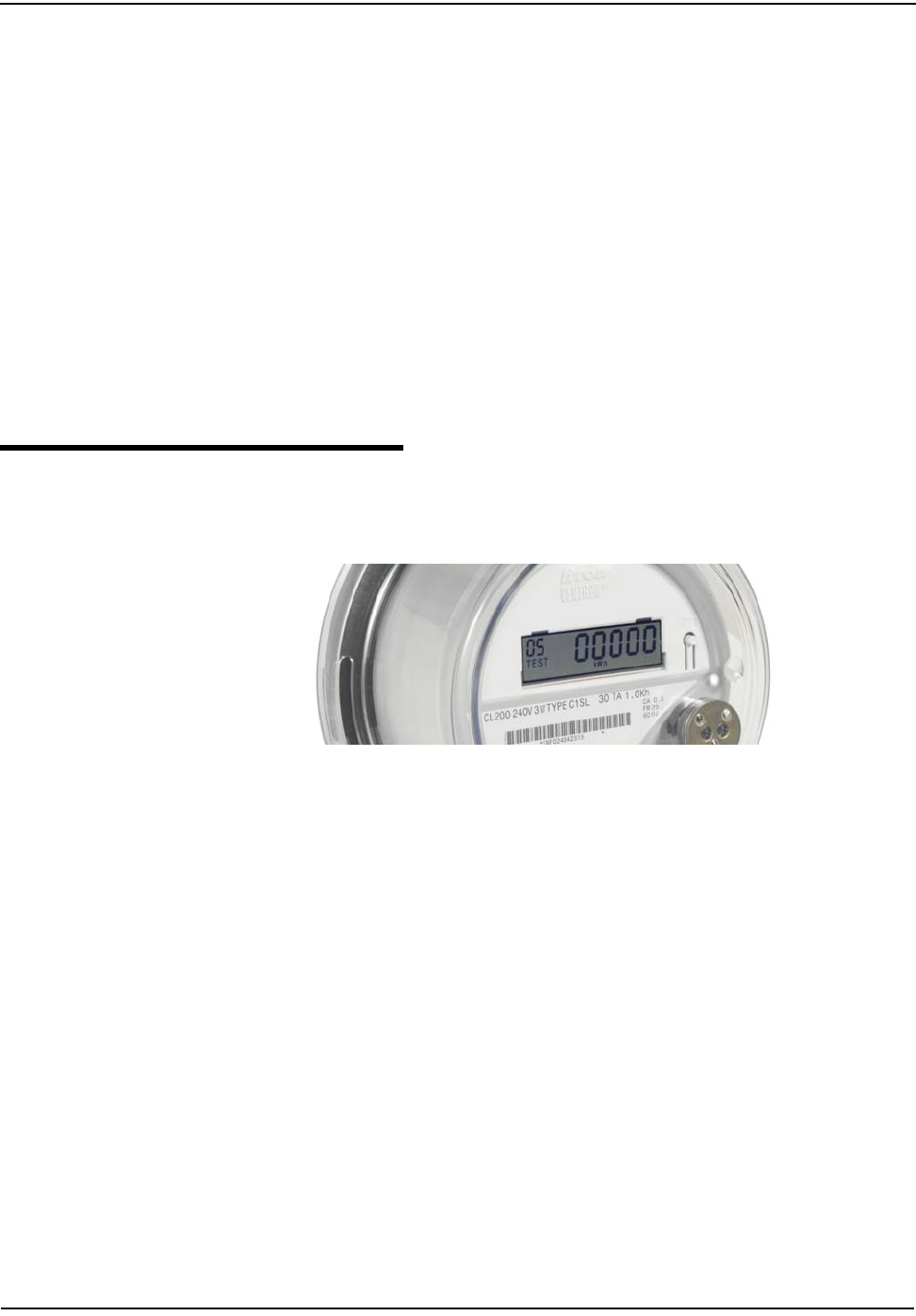
Operation: C1SD, C1ST, and C1SL Versions
CENTRON Meter Technical Reference Guide 5-5
Low Power Mode
The demand, TOU, and load profile modules are shipped from the factory in low
power mode unless factory programming is specified at time of order. This mode
consists of a default program and minimizes drain on the battery. The user can
place the meter in low power mode by performing a three button reset or by
programming the meter with the programming software as a demand-only meter.
While the module is on battery carryover, the display will show “on battry” while
the power is off. This can be observed by viewing the display at an angle at close
range.
Low power mode can be verified in one of the following ways:
• By observing that the minutes on battery counter does not increase during a
power outage.
• By observing the display during a power outage (from close range at an angle)
and verifying that the display does not show “on battry”.
See "Three Button Reset" on page 5-27 for instructions.
Displays
A nine-digit liquid crystal display, with a variety of annunciators, is provided on
these multifunction personality modules (see Figure 5.4).
Figure 5.4 Display
Six large digits are available to display all billing and informational data. Three
decimal points are provided for programmable resolution of billing data.
Three small digits in the upper left-hand corner of the display are used to provide
code numbers to identify any display item. These three digits are used along with
the six data digits to display ID numbers such as the meter serial number and user
fields.
There are three triangle segments in the bottom right corner of the display that
represent a watt disk emulator. This electronic load indicator will advance with
each pulse, since each pulse is equivalent to one watthour. Reverse power is
indicated by a reversal in the direction of the electronic load indicator.
Directly below the three code number digits is the Test mode annunciator (TEST).
This annunciator will flash on and off once per second whenever the meter is in
Test mode.
On the far left of the bottom line is the Alternate mode annunciator (ALT). This
annunciator will flash on and off once per second whenever the meter is in
Alternate mode.
To the right of the Alternate mode annunciator are the TOU rate indicators (A, B,
C, D, Total). These indicators correspond to the four programmable TOU and
TOTAL rate. The TOU rate indicators can be programmed to be displayed with the
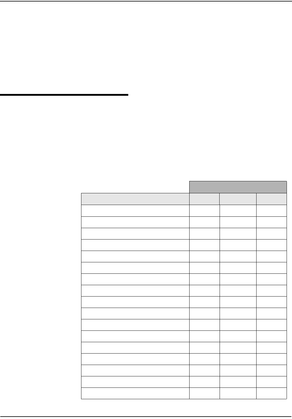
Operation: C1SD, C1ST, and C1SL Versions
5-6 CENTRON Meter Technical Reference Guide
appropriate energy and demand quantities. When an energy or demand quantity for
the currently active TOU rate (A, B, C, or D) is displayed, the corresponding TOU
rate indicator will flash on and off once per second.
To the right of the TOU rate annunciators is the kWh annunciator. This annunciator
can be programmed to display with any energy quantity. The kWh annunciator can
be programmed to display as kW with any demand quantity.
The EOI annunciator is located to the right of the kWh annunciator. This
annunciator will turn on for four seconds at the end of each demand interval (or at
the end of each subinterval when rolling demand is used).
Programmable Functions
The CENTRON can be programmed using Itron programming software: PC-PRO+
or PC-PRO+ 98.
Table 5.1 describes each display item and indicates the display mode in which each
is available. The display items and sequence of their display, along with any desired
annunciators or Identification (ID) code numbers, are selected during the
programming process. Detailed information on these display items can be found in
the PC-PRO+ documentation.
Table 5.1 LCD Display Items
Display Mode
Display Item Normal Alternate Test
kWh xxx
Maximum kW Demand x x x
Cumulative kW Demand x x
Continuous Cumulative kW Demand x x
Previous Interval kW Demand x x x
Self Read kWh x x
Self Read kW Demand x x
Last Season Billing Values (TOU only) x x
Present Interval Demand kW Demand x x
Segment Test x x
Time Remaining in (Sub) interval x x
Meter ID (up to two 9-digit fields) x x
User Defined Fields (up to three 9-digit fields) x x
Firmware Version x x
Software Version x x
Number of Times Programmed x x
Number of Demand Resets x x
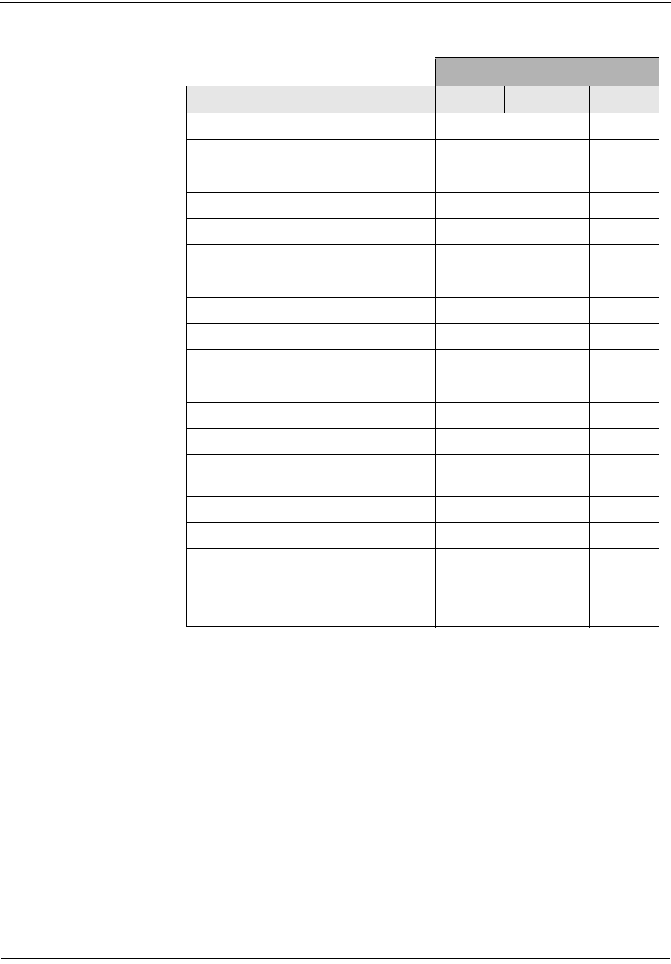
Operation: C1SD, C1ST, and C1SL Versions
CENTRON Meter Technical Reference Guide 5-7
Register Display Options
All calculated billing quantities to be displayed are specified through the
programming software. The following billing quantities are available for display in
the Normal and Alternate modes:
•kWh
• Received kWh
• Max kW Demand
• Cumulative kW Demand
• Continuous Cumulative kW Demand
• Previous Interval kW Demand
• Self-read kWh
• Self-read kW Demand
Number of Power Outages x x
Number of Days Since Demand Reset x x
Demand (Sub) interval Length x x
Register Full Scale Value x x
Kh Value x x
Demand Threshold Value x x
P/DR Value x x
Register Multiplier x x
Date (C1ST and C1SL version only) x x
Time (C1ST and C1SL version only) x x
Day of Week (C1ST and C1SL version only) x x
Date of Last Reset (C1ST and C1SL version only) x x
Time of Last Reset (C1ST and C1SL version only) x x
Time on Battery Carryover (min) (C1ST and C1SL
only) xx
Program ID Number x x
TOU Schedule ID (TOU only) x x
Input Pulse Count x
Previous Interval Pulse Count x
Time Remaining in Test Mode x
Table 5.1 LCD Display Items
Display Mode
Display Item Normal Alternate Test
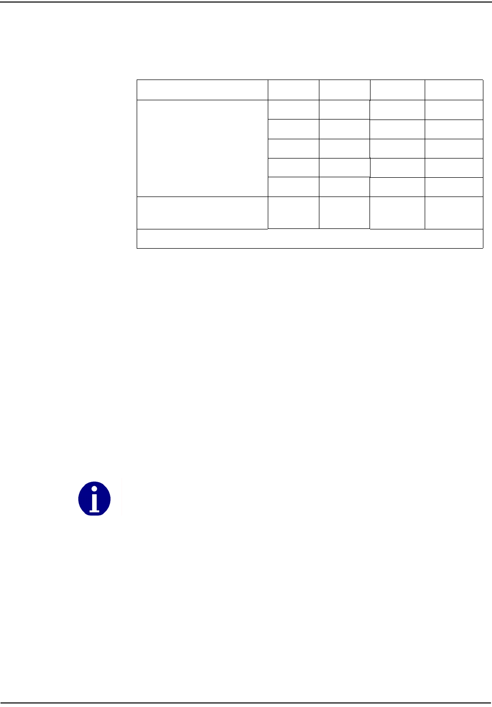
Operation: C1SD, C1ST, and C1SL Versions
5-8 CENTRON Meter Technical Reference Guide
Energy and demand registers can be programmed to be displayed in any of the
specified formats (see Table 5.2).
Self Reading
The C1SD is capable of storing one block of self-read data consisting of kWh and
maximum kW. The TOU versions, the C1ST and C1SL, will store one block of self
read data consisting of kWh and kW for all rates when a self-read is performed.
Self-read data is displayable in Normal or Alternate mode.
A self-read is programmed to initiate in one of three ways:
• Read on manual or electronic demand reset. When a demand reset is initiated,
all energy and maximum demand quantities are immediately transferred to
non-volatile memory.
• Read on a programmed day of the month (C1ST and C1SL only). A specified
date (1st - 28th) can be programmed into the meter to indicate the exact day
that a self-read is to be performed. On this date at 00:00 hours, register
readings are transferred to nonvolatile memory.
If desired, an automatic demand reset can be performed after this self-read.
• Read on a programmable number of days since the last manual or automatic
demand reset (C1ST and C1SL only). If the selected number of days (1 to 150)
passes without a demand reset, a self-read is initiated.
If desired, an automatic demand reset can be performed after this self-read.
Table 5.2 Register Display Formats
3 Digits 4 Digits 5 Digits 6 Digits
Demand
X.XXX XX.XXX XXX.XXX
X.XX XX.XX XXX.XX XXXX.XX
XX.X XXX.X XXXX.X XXXXX.X
XXX XXXX XXXXX XXXXXX
X.X.X* X.X.X.X* XX.X.X.X* XXX.X.X.X*
Energy XX.X
XXX XXX.X
XXXX XXXX.X
XXXXX XXXXX.X
XXXXXX
*indicates floating decimal point format
Only the first 28 days of the month can be selected since February has only 28 days.

Operation: C1SD, C1ST, and C1SL Versions
CENTRON Meter Technical Reference Guide 5-9
Last Season Registers
For a C1ST or C1SL meter, Last Season Registers are selectable in the
programming software. For every Current Season Register there is a Last Season
Register for the same quantity. Last Season registers are stored in memory when a
season change occurs. Last Season registers are designated as LS in the
programming software. Last Season Registers are selectable for display in Normal
and Alternate modes.
Operating Parameters
Programmable parameters establish the meter's configuration and define its
operation in Normal, Alternate, and Test modes (see Table 5.3). Only parameters
specific to the Test mode are displayable in Test mode. Parameters that can be
uploaded using a reading device, but cannot be displayed on the meter are
indicated with an asterisk.
Table 5.3 Programmable Parameters
Parameter Description
Display Scroll Time * The number of seconds (1 to 15) that each item is to be
displayed before the next item appears.
Cold Load Pickup Time *(CLPU)
The number of minutes (0-255) before demand
calculations are restarted after a recognized power
outage occurs. Setting this value to zero will cause
demand calculations to start immediately following a
power outage.
Power Outage Length Prior to CLPU *
The number of minutes (0 to 255) that power must be
out for the CLPU to take effect. Defining this value as
zero will cause CLPU to be activated after any
recognized power outage.
Normal Mode Demand Interval Length The time in minutes (1 to 60) that each demand interval
lasts before a new interval begins. Valid interval lengths
are 1, 2, 3, 4, 5, 6, 10, 12, 15, 20, 30, and 60 minutes.
Test Mode Demand Interval Length*
The time in minutes (1 to 60) that each Test mode
demand interval lasts before a new interval begins. Valid
interval lengths are 1, 2, 3, 4, 5, 6, 10, 12, 15, 20, 30,
and 60 minutes.
Normal Mode Number of Subintervals*
The interval length divided by the sub-interval length is
equal to the number of subintervals. Valid entries are
from 1 to 10 and must be evenly divisible into the
demand interval length. For block demand, the number
of subintervals is 1.
Test Mode Number of Subintervals*
The interval length divided by the sub-interval length is
equal to the number of subintervals. Valid entries are
from 1 to 10 and must be evenly divisible into the
demand interval length. For block demand, the number
of subintervals is 1.

Operation: C1SD, C1ST, and C1SL Versions
5-10 CENTRON Meter Technical Reference Guide
Informational Data
The following items are for information purposes (see Table 5.4). All informational
data, except those items indicated by an asterisk, can be displayed in Normal and
Alternate modes.
Register Full Scale A kW demand value that defines the maximum rated
demand for a particular meter installation. Valid entries
range from 0 to 999999.
Test Mode Timeout
The number of minutes the meter will remain in Test
mode before exiting to Normal mode. This timeout
function is active when Test mode has been activated via
remote communications. Valid entries range from 1 to 99
minutes.
Operating Frequency* The operating frequency must be programmed to 50 Hz
or 60 Hz line operation.
Line or Crystal Sync* The real time clock can be synchronized off the input line
frequency or the internal crystal.
Register Multiplier
A programmable value that is used in calculations of
energy and demand readings. This can be used by
setting the register multiplier equal to the CT ratio times
the PT ratio of the installation for primary read meters.
Valid entries are from 1 to 9999.
Note: Energy and demand display formats should be
adjusted accordingly.
Optical Communications Baud Rate* The optical communications default baud rate is 4800
baud, however, a rate of 9600 baud is selectable.
Expansion Port Comm. Baud Rate* The expansion port communications default baud rate is
2400 baud; however, rates of 300, 1200, 2400, 4800,
and 9600 baud are selectable.
*Indicates parameters that can be uploaded to a reading device but cannot be displayed.
Table 5.3 Programmable Parameters
Parameter Description
Table 5.4 Information Data Items
Item Description
Time and Date of Maximum Demands
(C1ST and C1SL only) The time and date that each maximum demand occurred
for A, B, C, D and Total Rates.
Time Remaining in (Sub) interval The amount of time in minutes and seconds before the end
of the current demand interval.
Segment Test The display illuminates all segments and selected
annunciators on the LCD in order to verify proper operation.
The watt disk emulator continues to function normally.

Operation: C1SD, C1ST, and C1SL Versions
CENTRON Meter Technical Reference Guide 5-11
Meter ID Numbers 1 and 2
Two separate nine digit display items that can be used to
identify the meter with an alpha character displayed as a
dash, a space displayed as a blank, and a number
displayed as the appropriate value.
User Fields
Up to three separate user fields are available to display any
desired numerical information. Each user field can be up to
nine digits in length with an alpha character displayed as a
dash, a space displayed as a blank, and a number
displayed as the appropriate value.
Firmware Revision A sequential number identifying the firmware revision level
of the meter. This number is automatically provided and
does not require operator input.
Software Revision
A sequential number identifying the revision level of the
software used to program the meter. This number is
automatically provided by the programming software and
does not require operator input.
Number of Times Programmed A counter identifying the number of times (up to 9999) the
meter has been programmed.
Number of Power Outages A counter identifying the number of times (up to 9999) the
meter has recognized a power outage.
Number of Demand Resets A counter identifying the number of times (up to 9999) a
demand reset has occurred.
Number of Days Since Demand Reset
(C1ST and C1SL only) A counter identifying the cumulative number of in service
days since the last demand reset.
Date and Time of Last Reset (C1ST and
C1SL only) The date and time of the last demand reset.
Date and Time Last Programmed (C1ST
and C1SL only) The date and time the meter was last programmed.
Date (C1ST and C1SL only) The current date recognized by the meter
Time (C1ST and C1SL only)
The current time recognized by the meter.
Note: For time of occurrence registers, time is displayed as
HH:MM:SS. All dates are displayed in the format chosen in
the programming software.
Day of Week (C1ST and C1SL only) A single digit denoting the current day of the week is
displayed where Monday is denoted by a one and Sunday
by a seven.
Time on Battery (C1ST and C1SL only) A counter identifying the cumulative number of minutes, 0
to 999,999, the meter has been in battery carryover mode.
Program ID Number A three digit number identifying the program downloaded to
the meter.
TOU Schedule ID Number (C1ST and
C1SL only) A three digit number identifying the TOU rate schedule
downloaded to the register.
Table 5.4 Information Data Items
Item Description

Operation: C1SD, C1ST, and C1SL Versions
5-12 CENTRON Meter Technical Reference Guide
Test Mode Data
The following items shown in Table 5.5 can be displayed in Test mode.
TOU Expiration Date * A date that indicates when the register's TOU schedule will
no longer be valid.
Register Full Scale Value A kW demand value that represents the maximum rated
demand for a particular meter installation. Exceeding this
value triggers error code 100000.
Demand Threshold Value A programmed threshold value in kW that determines when
the demand threshold output turns on.
Mass Memory Size * (C1SL only) The amount of mass memory actually being used for
recording of interval data. Valid entries are 0 to 32K, in 8K
increments.
Note: * Indicates parameter that can be uploaded to a reading device but cannot be displayed.
Table 5.4 Information Data Items
Item Description
Table 5.5 Test Mode Data Items
Item Description
Time Remaining in the (Sub) interval The amount of time in minutes and seconds before the end
of the current Test mode demand interval.
Maximum kW The maximum demand since the meter was put into Test
mode. This value will be set to zero each time a demand
reset is performed.
Previous kW The kW demand of the previous Test mode subinterval/
interval.
Input Pulse Count The number of pulses that have been received since the
last reset in Test mode.
Note: The display will be updated with each input pulse.
Previous Interval # of Input Pulses The number of pulses received during the last complete
interval or subinterval in Test mode.
kWh The energy accumulated in Test mode.
Present (Accumulating) kW The calculated demand value as it increases from the start
of a demand test interval to the end of the subinterval/
interval.
Time Remaining until Test Mode
Timeout The amount of time in minutes and seconds before the
programmed Test mode timeout counter will expire.
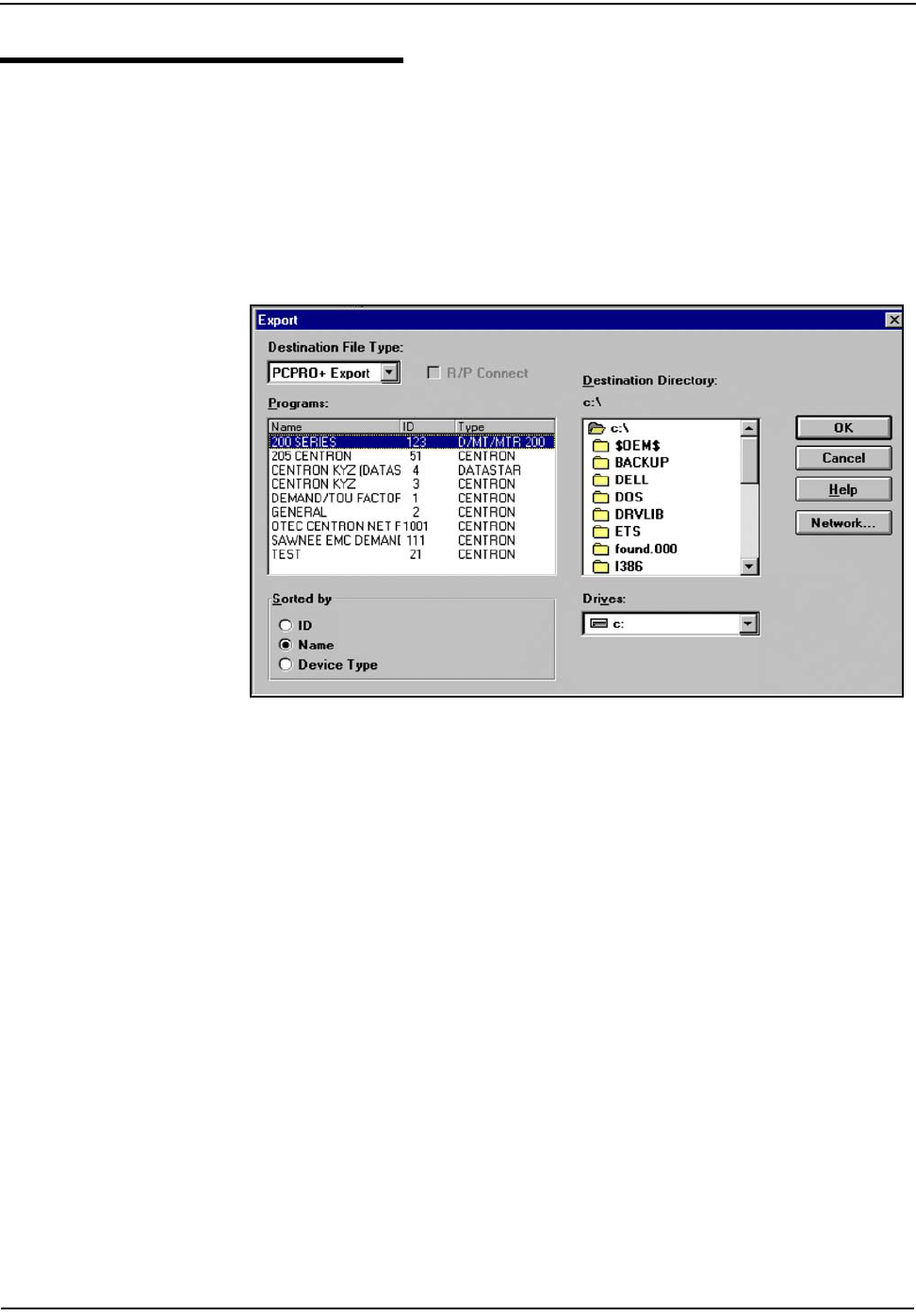
Operation: C1SD, C1ST, and C1SL Versions
CENTRON Meter Technical Reference Guide 5-13
Programming the Meter With a 200 Series Program
A CENTRON meter can be programmed using an existing Series 200 program. This
procedure is a two-step process. First, export the 200 Series program you want to
use to a CENTRON file format and then import that file into PC-PRO+ as follows:
1 Open the Program Editor.
2 Select File | Export.
The Export screen shown in Figure 5.5 is displayed.
Figure 5.5 Program File Export
3 Select the 200 Series program to export from the list of available Programs.
4 Click OK.
The Program File Export Type screen is displayed.
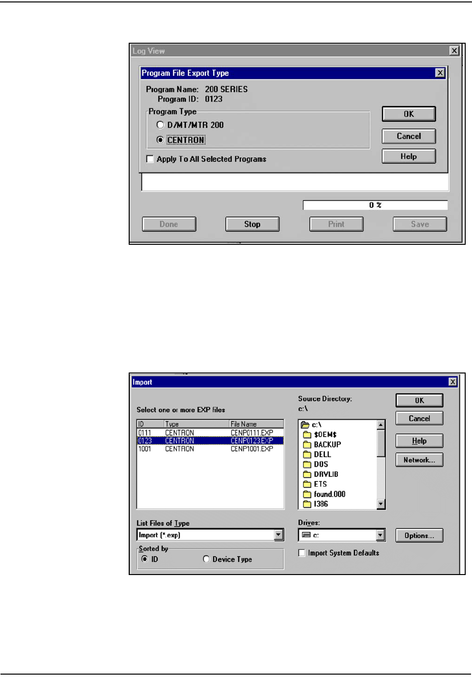
Operation: C1SD, C1ST, and C1SL Versions
5-14 CENTRON Meter Technical Reference Guide
Figure 5.6 Program File Export Type
5 Select CENTRON export format as shown in Figure 5.6 above.
6 Click OK.
The file you selected in Figure 5.5 is converted to a CENTRON format. The
program ID remains the same, but the file type becomes CENTRON.
7 Select File | Import.
The Import screen shown in Figure 5.7 is displayed.
Figure 5.7 Import Screen
8 Select the CENTRON program to import from the list of available EXP files.
9 Click OK.
The program is loaded into the Program Editor. Edit as necessary before
saving and using to program the meter.

Operation: C1SD, C1ST, and C1SL Versions
CENTRON Meter Technical Reference Guide 5-15
Demand Reset
A demand reset can occur in both Normal and Alternate modes.
A demand reset can occur in two ways:
• Through the optical port using a compatible programming device
• With the standard push-button demand reset switch located on the face of the
meter (see Figure 5.2)
When a demand reset is initiated, the following events occur:
• As an indication of a demand reset, the display flashes all eights for six
seconds.
• The current maximum demand values are added to the corresponding
Cumulative Demand values.
• A self-read is performed (if selected).
• All Maximum Demand values are reset to zero. All corresponding times and
dates of maximum demands are cleared (C1ST and C1SL only).
• The number of demand resets is increased by one.
• The number of in-service days since the last reset is set to zero.
• The time and date of the last reset is updated (C1ST and C1SL only).
• The normal mode display resumes. Exception is when in test mode, the display
resumes with next item in display list.
As a security feature, additional manual demand resets are prevented for 60
seconds following a demand reset.
Time-of-Use
TOU Schedules
The Time-of-Use capability is available on the C1ST and C1SL personality modules.
It requires additional circuitry to store TOU schedule information and a battery for
time-keeping purposes during power outages. Schedule information is
programmed on a PC using the PC PRO+ software packages.
When using TOU functions on a meter, energy and demand registration are
segregated into time blocks during the day. Each time block can be one of four rate
periods. In addition to these four rate periods, a total rate is also available.
Calendar Schedule
The calendar schedule contains all daily and yearly information necessary to
perform TOU metering. This schedule contains rate schedules, daily schedules,
seasons, holidays, and daylight savings time dates. For information on the entry of
these parameters into PC-PRO+, refer to the PC-PRO+ documentation.
When a demand reset is performed on a meter programmed for Block Demand, the current
interval becomes the first interval in the next billing period. For Rolling Demand, all previously
completed subintervals are zeroed. The current subinterval becomes the first subinterval in the
next billing period. In Test mode, a demand reset will initialize the demand test interval.

Operation: C1SD, C1ST, and C1SL Versions
5-16 CENTRON Meter Technical Reference Guide
Rate Schedules
Four independent rates are available for TOU registration-designated A, B, C, and
D. Only one of these rates can be active at a time. The Total register is always
active, regardless of the active rate period. The currently active rate is indicated by
a flashing rate-specific annunciator.
Daily Schedules
Up to four daily schedules are available. Each schedule defines the beginning and
ending time of each of the four available rate periods (A, B, C, and D). Up to 32
switch points per rate may be specified for each daily schedule.
Weekdays, Saturday, Sunday, and holidays can be assigned to one of the four daily
schedules. Therefore, one to four daily schedules may be used in any combination
with the days of the week.
Seasonal Schedules
A season is a period of continuous days during the year when a particular rate
schedule is in effect. The year can be divided into a maximum of eight seasons. If
multiple seasons are not used, the TOU schedule contains one year-round season.
The Daily Schedules can be defined differently for each season. Up to eight Season
Change dates are specified for each year in the Calendar Schedule.
Season changes occur at midnight of the Season Change date (where midnight
corresponds to 00:00 hours) or can be programmed to occur at the first demand
reset following the Programmed Season Change date.
Holiday Schedules
Up to twenty-two holidays can be designated per year in the Calendar schedule.
One of the four Daily schedules is assigned to each of the Holidays in the Calendar
Schedule.
Daylight Savings Time
Daylight Savings Time switch points occur at 2:00 A.M. on the first Sunday in April
and the last Sunday in October. These dates are pre-assigned in the Calendar
Schedule; however, they can be modified by the user. The user can also elect not to
recognize Daylight Savings Time and operate the meter in standard time only.
Registers
Current Season Register
All energy and demand registers selected for the active season are considered
current season registers. If a single rate schedule is applicable year-round, then
only current season registers are used.

Operation: C1SD, C1ST, and C1SL Versions
CENTRON Meter Technical Reference Guide 5-17
Last Season Registers
Last Season Registers are selected when two or more seasons are used during the
year. For every Current Season Register there is a Last Season Register for the
same quantity. Last Season Registers are designated LS in the programming
software. Last Season Registers can also be selected for display in Normal and
Alternate display modes.
Operation
At the end of a specified season, all Last Season Registers are updated with
Current Season register data. The meter can be programmed to activate an
automatic demand reset at a season change. A season change can be programmed
to occur at midnight at the beginning of the programmed Season Change date or at
the first demand reset following the Season Change date.
Season Change
The following events take place when an automatic demand reset occurs at season
change:
• The Current Season energy registers are copied directly to the Last Season
energy registers.
• The Current Season maximum demand registers are copied directly to the Last
Season maximum demand registers and added to the cumulative demand
registers.
• After the demand reset, the maximum demand registers are reset to zero. Both
the cumulative and the continuous cumulative demand registers are copied to
the Last Season cumulative and continuous cumulative demand registers,
respectively.
If there is no demand reset at season change, all current season registers are
directly copied to Last Season registers at season change but no current season
registers are zeroed.
Load Profile Specifications
Capacity
The C1SL module provides 32k bytes of EEPROM for one channel of interval load
profile data. The amount of installed EEPROM actually used for load profile
recording is programmable from 1 to 32k bytes in one kbyte increments.
Bit Resolution
The mass memory is configured for 12 bit data resolution. Equivalent pulse count
resolution per interval is as follows:
Bits = 12
Pulse Counts = 4096
34 bytes of the 32k bytes is reserved for firmware and software parameters.

Operation: C1SD, C1ST, and C1SL Versions
5-18 CENTRON Meter Technical Reference Guide
Interval Lengths
The load profile records data on a block interval basis. The interval length is
programmable: 1, 2, 3, 4, 5, 6, 10, 12, 15, 20, 30, or 60 minutes. This interval length is
independent of the interval length chosen for displayed demand quantities.
Power Outage
The C1SL module can flag an interval when a power outage exceeds a specified
number of seconds. The power outage duration is programmable from 0 to 255
seconds.
Channel Configurations
The Load Profile register has one channel of interval load profile data. This
channel corresponds to kWh. The pulse constant is programmable from 0.02 to
99,999 watthours per pulse in 0.01 increments. This pulse constant applies to
secondary readings only. For example, a watthour pulse constant of 1.8
corresponds to 1.8 watthours per pulse.
Some example pulse weight calculations:
Example 1: Calculation of Pulse Weight
If the customer pulls a 240V, CL200, singlephase, Form 2S electromechanical meter
from service, with the following:
Meter Kh = 7.2 watthours/disk revolution
Pulse Initiator = 4 pulses/disk, revolution
then this electromechanical meter has the following pulse weight (PW):
If this meter is replaced by a Load Profile register of the same form number,
voltage and current ratings, and if the utility wants the register to operate the same
way, the pulse weight would be entered in the customer files as 1.8 watthours per
pulse.
Example 2: Calculation of Pulse Weight
A Load Profile register on a singlephase, 240V, CL200, meter is programmed so that
kWh is recorded into mass memory. The maximum 12-bit data resolution is desired
for 15 minute intervals.
First, calculate the maximum watthour accumulation during 15 minutes intervals:
PW Kh
PDR
-------------7.2 watt hours
disk revolution
--------------------------------------
⎝⎠
⎛⎞
4 pulses
disk revolution
--------------------------------------
⎝⎠
⎛⎞
⁄==
PW 1.8 watt hours
pulse
--------------------------------------
=
Wh Max,240volts 200A 1phase 0.25×××=
Wh Max,12 000 watt hours,=

Operation: C1SD, C1ST, and C1SL Versions
CENTRON Meter Technical Reference Guide 5-19
The maximum number of pulses is 4095; therefore, the smallest pulse weight (PW)
that can be used is:
Data Storage
The Load Profile register stores data in mass memory at the end of each interval.
This data stored is the pulse data for that interval. This process continues for each
interval until sixty intervals have been recorded. The mass memory is grouped into
segments of sixty intervals defined as a record or block. In addition to the profile
data, each record contains the following information:
Recording Duration
Use the following equation to determine the recording duration for the load profile
register:
M= Memory size in kilobytes
I = Interval Length in minutes
PW Min,12 000Wh,
4095P
-----------------------------2.94Wh
Pulse
---------------------
==
Time Tag Specifies the month, day, and hour of the end of the data
record (or block).
Power Outage Status bit is set for each interval during which a power
outage occurs (interval status).
Status Bits There are four types of status bits written into each data
block:
Time Adjust Status bit set along with power outage bit when time is
adjusted with Load Profile running.
Saturation Status bit is set when the pulse count for any interval in
the block exceeds 4,095 pulses.
RAM Error Status bit is set if any memory address within the record
fails the memory check (block status).
Field Test Status bit is set if Test mode is activated during an interval.
Register Readings A register reading is maintained in the data record to be
used for data validation. This register reading is updated
at the end of each interval.
Duration (days) M 1024×
107
------------------------ I
24
------
×=
Truncate all decimals before multiplying by I/24.

Operation: C1SD, C1ST, and C1SL Versions
5-20 CENTRON Meter Technical Reference Guide
Optional Features
Electronic Detent
Programming electronic detent prevents received energy from accumulating in the
delivered energy register. When detent is enabled, the received energy is
accumulated in a separate register.
Expansion Port
A connector located on these personality modules provides the option of using
expansion modules (when available), such as the R300CD board in conjunction
with the C1SD, C1ST, and C1SL personality modules.
Security Codes
Register security can be provided with primary, secondary, and tertiary security
codes that prevent unauthorized communication with CENTRON products. A
Primary security code allows complete access to the meter. A Secondary security
code allows full read access with limited write access to perform an automatic
demand reset and to access the Alternate and Test modes. A tertiary security code
allows read-only access. For more information about security codes, refer to the
PC-PRO+ documentation.
Table 5.6 Recording Duration for 32Kb
Interval Length (min) Recording Duration
(days)
1 12.75
2 25.50
5 63.75
10 127.50
15 191.25
30 382.50
60 765.00

Operation: C1SD, C1ST, and C1SL Versions
CENTRON Meter Technical Reference Guide 5-21
Calculations
Energy
Calculation of energy is continuously incremented by multiplying the energy pulse
weight by the measured energy. The energy pulse weight is calculated by the
following formula:
The energy in a given interval is the product of the number of pulses received
during that interval times the pulse weight:
Demand
Calculation of demand is always based on rolling or block intervals. Demand
calculations use three constants; the watthour constant (Kh), the demand interval
length, and the register multiplier.
The weight of an incoming pulse is determined according to the following formula:
The demand in a given interval is the product of the number of pulses received
during that interval times the pulse weight:
The Demand value is continuously compared against the stored maximum value. If
a demand value is greater than the corresponding maximum demand, it is saved as
the new maximum demand. If the demand value is less than the corresponding
maximum demand, it is discarded. At the beginning of an interval, the current
interval demand is reset to zero and new demand values begin accumulating.
kWh Pulse Weight kwh
Pulse
----------------
⎝⎠
⎛⎞
Kh 1000×Register Multiplier==
Energy kWh()Number of Pulses kWh
Pulse
----------------
⎝⎠
⎛⎞
×=
kW pulse weight kw
pulse
---------------
⎝⎠
⎛⎞
Kh 1000 Register Multiplier 60/Dem. Int. Length××⁄=
Demand kW()Number of Pulses kW Pulse Weight×=

Operation: C1SD, C1ST, and C1SL Versions
5-22 CENTRON Meter Technical Reference Guide
Demand Calculations
Block Interval Demand
Block demand corresponds to the number of subintervals being equal to one. At
the end of every interval, the microprocessor compares the last completed block
interval demand value to the demand value in memory. If the new value is greater
than the stored value, the new demand value is stored as Maximum Demand. When
a demand reset occurs, maximum demands are reset to zero and the current
interval continues. C1SD will begin a new demand interval. New maximum
demand values are calculated.
Rolling Interval Demand
For rolling interval demand, the programmed number of subintervals make up the
demand interval. At the end of every subinterval, the microprocessor calculates a
demand value based on the last full demand interval. When a demand reset occurs,
all Maximum Demands are reset to zero along with all completed subintervals. The
current subinterval continues (unless C1SD) accumulating data and the new
maximum demand value(s) is (are) calculated for the next subinterval.
Cumulative Demand
When a demand reset is performed, Maximum Demand values are added to the
existing corresponding Cumulative Demand values and written into memory as the
new Cumulative Demand values. These values remain in storage until the next
demand reset.
Continuous Cumulative Demand
Continuous Cumulative Demand is the sum of Maximum and Cumulative Demand
at any time. The calculated interval demand is continuously compared to the
previous Maximum Demand. If this demand is a new peak, it is stored as a
Maximum Demand and adjusts the continuous cumulative register to reflect the
new demand. A demand reset signal clears the Maximum Demand value, but does
not affect the Continuous Cumulative reading.
Previous Interval Demand
Previous interval demand is the calculated demand from the most recently
completed demand interval. When using rolling interval demand, this quantity is
updated after each subinterval. Previous interval demand is not saved in non-
volatile memory. When an interval is completed the demand value is transferred to
the previous interval demand register for display. Upon power up or demand reset,
the previous interval demand register is set to zero and is updated when the first
subinterval is complete.
Present Interval Demand
The present interval demand value is the demand value at the present time
normalized to the demand interval length. Present demand reports the calculated
demand value as it increases from the start of a demand interval to the end of the
interval. For rolling demand intervals, present demand reports the calculated
demand value from the present subinterval as it is accumulating with the previous
set of subintervals.
Operation: C1SD, C1ST, and C1SL Versions
CENTRON Meter Technical Reference Guide 5-23
Power Procedures
Applying Power
Personality Modules are powered directly from line voltage via the board-to-board
connector. These modules are energized when AC power is present. During power
outages, the permanently installed lithium battery runs the clock circuit on C1ST
and C1SL versions. The battery normally lasts for the life of the meter. However, in
the unlikely event of a low battery notification, the battery or Register Module may
need to be replaced.
Battery Life (Load Profile & TOU)
The CENTRON TOU and Load Profile personality modules have a permanently
soldered battery present on their circuit boards. This battery powers the clock
when power is disconnected from the meter. The module program is transferred to
EEPROM for recall when power is restored.
The battery life is longer for the CENTRON TOU and Load Profile modules than
the J5 200 Series electromechanical hybrid meters. The capacity of the new battery
is larger than equivalent older products, and the current consumption is reduced
with new electronics technology.
In the process of determining this factor, battery life calculations are made
assuming worst case conditions for both the battery capacity (at the lowest end of
the manufacturer published initial limit) and the meter current consumption
(assuming all the components are at the maximum side of their published
tolerance).
The CENTRON battery life is illustrated in Figure 5.8.
Do NOT remove the electronics housing while the meter is powered. Line level voltages
are present on the circuit board. Failure to follow this procedure could result in serious
personal injury or death. The warning label should always be visible on the housing.
Meters shipped from the factory unprogrammed or meters removed from the field and given a
3-button reset will not use battery carryover time.
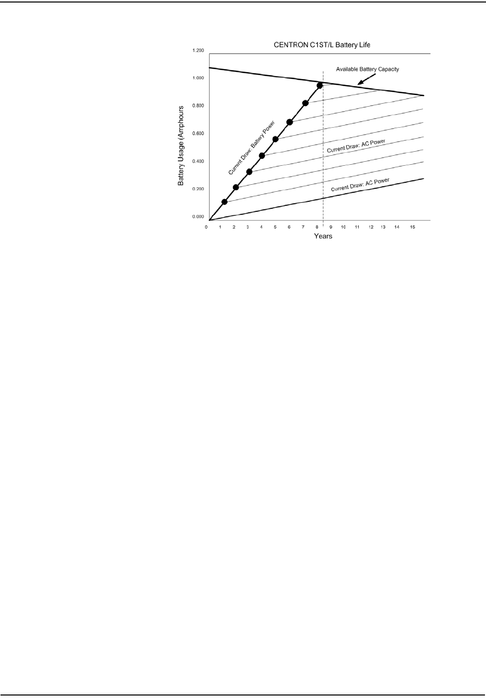
Operation: C1SD, C1ST, and C1SL Versions
5-24 CENTRON Meter Technical Reference Guide
Figure 5.8 CENTRON C1ST/L Battery Life
An explanation of Figure 5.8 is as follows:
The Available Battery Capacity line is a function of time. Recent changes made to
the design (optimized battery current consumption at the transition phase from AC
power ON to AC power OFF), allowed the CENTRON to further improve the
available battery budget over time.
With the estimated available battery capacity, a carryover capacity of 8 years is
shown by the cross over point between the Available Battery Capacity curve and
the Battery Usage when the meter is not powered curve.
A very small amount of current is required to keep the real time clock running
when the meter is not powered from the AC line. The clock is running from
battery power (when not powered from the AC line) when the meter is
programmed with a TOU or LP configuration that requires clock or calendar
functionality. An even smaller amount of current is required of the battery while
the meter is powered or is in low power mode. The meter is in low power mode
when the meter is programmed with a demand only configuration (no clock or
calendar functions) or when given a three button reset. The lower Current Draw
AC Power line on Figure 5.8 represents this lowest current (low power mode or AC
power). When the meter is either powered from the beginning of life or in low
power mode, the available battery capacity is not used until beyond 15 years of
service life.
The series of lines is intended to help the user to assess the battery life under
different usage profiles (time while the meter is not powered versus time while the
meter is powered).
The following examples illustrate usage of the below Battery Life Graph.
Example 1
For example 1 (see Figure 5.9), the meter is unpowered (with battery running the
clock) for two years then installed in the field under AC power. Follow the Current
Draw: the Battery Power line from year zero to year two, then follow the Current
Draw: the AC Power line from year 2 to the right. This shows that the battery will
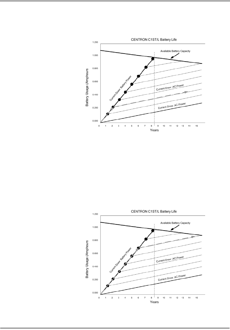
Operation: C1SD, C1ST, and C1SL Versions
CENTRON Meter Technical Reference Guide 5-25
not cross the Battery Capacity line until beyond year 15. The battery is not
considered depleted until the Current Draw line crosses the Available Battery
Capacity line.
Figure 5.9 Example 1
Example 2
For example 2 (see Figure 5.10), the meter is unpowered (with battery running the
clock) for six years then installed in the field under AC power. Follow the Current
Draw: the Battery Power line from year zero to year six, then follow the Current
Draw: the AC Power line from year 6 to the right. This shows that the battery will
not cross the Battery Capacity line until after year 15. The battery is not
considered depleted until the Current Draw line crosses the Available Battery
Capacity line.
Figure 5.10 Example 2
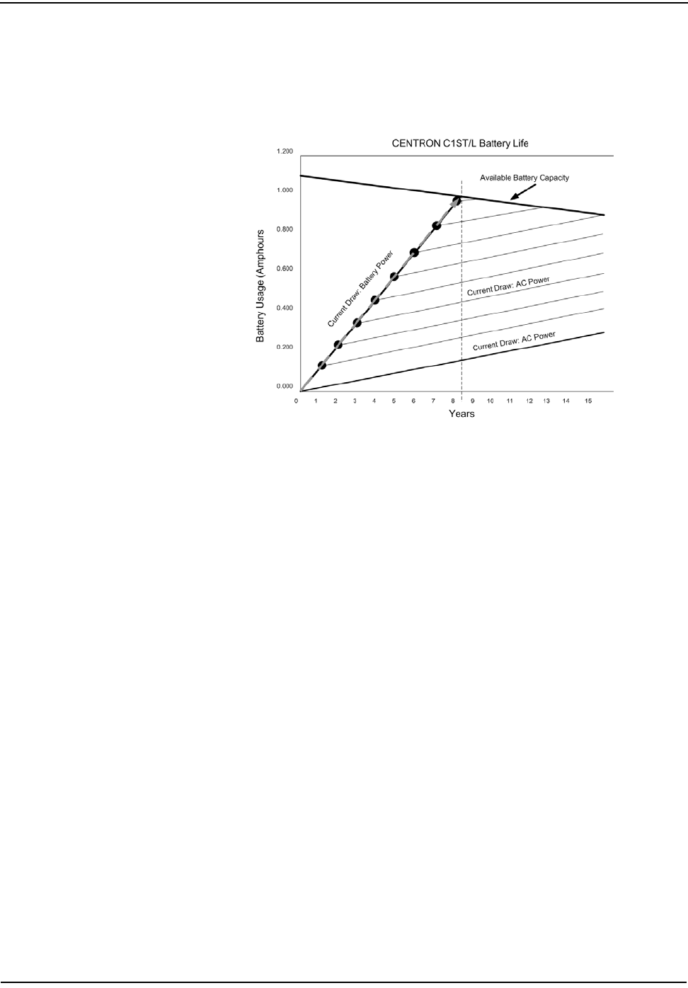
Operation: C1SD, C1ST, and C1SL Versions
5-26 CENTRON Meter Technical Reference Guide
Example 3
For example 3 (see Figure 5.11), the meter is unpowered (with battery running the
clock) for an infinite amount of time. This shows that the Current Draw line will
not cross the Battery Capacity line until past year 8.
Figure 5.11 Example 3
Low Battery Error
The TOU and LP module firmware counts minutes on battery (when the battery is
enabled) during power outages. Current production revision (10.30) firmware has
a hard coded limit which will trigger a Low Battery Error in the event that one year
of carryover has accumulated regardless of hardware revision. When a Low
Battery Error has been triggered on TOU or LP modules with part number 442701-
xxx, the module can be reprogrammed to clear the error. Alternatively, the Low
Battery Error can be set to be ignored via programming software. This is done by
opening the CENTRON program in PC-PRO+, and then selecting Displayable
Errors. When the list of displayable errors is shown, select Low Battery. The user
will be prompted to select Ignore, Scroll or Lock. Select Ignore and save this
configuration. Reprogram the meters with this saved file. If the meter is
programmed with the Low Battery Error set to Ignore, the error will be triggered in
the meter and stored in memory, but it will not be shown on the meter's display.
An ignored error can be read via software. A Low Battery error will NOT stop
TOU or Load Profile functions in the meter. If the battery has reached its end of
life and does not have sufficient capacity to run the clock during a power outage,
only then will clock functions like TOU and/or Load Profile stop functioning if
programmed.
The minutes on battery counter can store up to 999,999 minutes. When this
number is exceeded, the counter will rollover to zero. Rollover of minutes on
battery counter will not clear the Low Battery error. Low Battery Error can only
be cleared by reprogramming the meter and setting the minutes on battery field to
a value less than 525,500 minutes.

Operation: C1SD, C1ST, and C1SL Versions
CENTRON Meter Technical Reference Guide 5-27
Effectivity Date
Meters shipped after October 1, 2003 have this revision of hardware with extended
battery life capability. This revision of module can also be identified by the
inspection of the module part number etched into the module itself. This revision
has a part number of 442701-xxx. The previous revision with one year battery
carryover capability has a part number of 442079-xxx
Three Button Reset
To perform a three button reset, follow these steps:
1 Remove power to meter.
2 Remove the meter cover.
3 Activate the magnetic reed switch using a small magnet positioned at the 10
o’clock point of the meter.
4 Depress the test mode button and the demand reset button.
5 Apply power to the meter while simultaneously performing steps 3 & 4.
6 Remove the magnet; release the test mode and demand reset buttons after 3
seconds.
7 The meter display should alternate between CNTRON and Segment Test if
the reset is successful.
8 Replace the meter cover.
Option Boards
CENTRON R300CD Operation
The R300CD option provides two RF transmission messages for energy and
demand readings. It is programmed with two unit ID's, one for identifying energy
(kWh) related Standard Consumption Messages (SCMs), and one for demand
(kW). The even ERT ID number will always correspond to the energy value, and
the odd ID will always correspond to the demand value. Only the even ID number
will be displayed on the meter nameplate, and the demand ID will be the next
sequential number.
The R300CD transmits two different types of SCMs representing energy and
demand. This is the only mode of operation used by the R300CD. R300CD option
boards must be installed in a Time-of-Use (TOU) equipped (battery and full
calendar clock capability) CENTRON. The R300CD will interrogate the TOU
module once per minute and read the self read kWh and self read kW values. These
values will typically change only once per billing period.
Performing a three button reset returns selected program parameters to a default state.
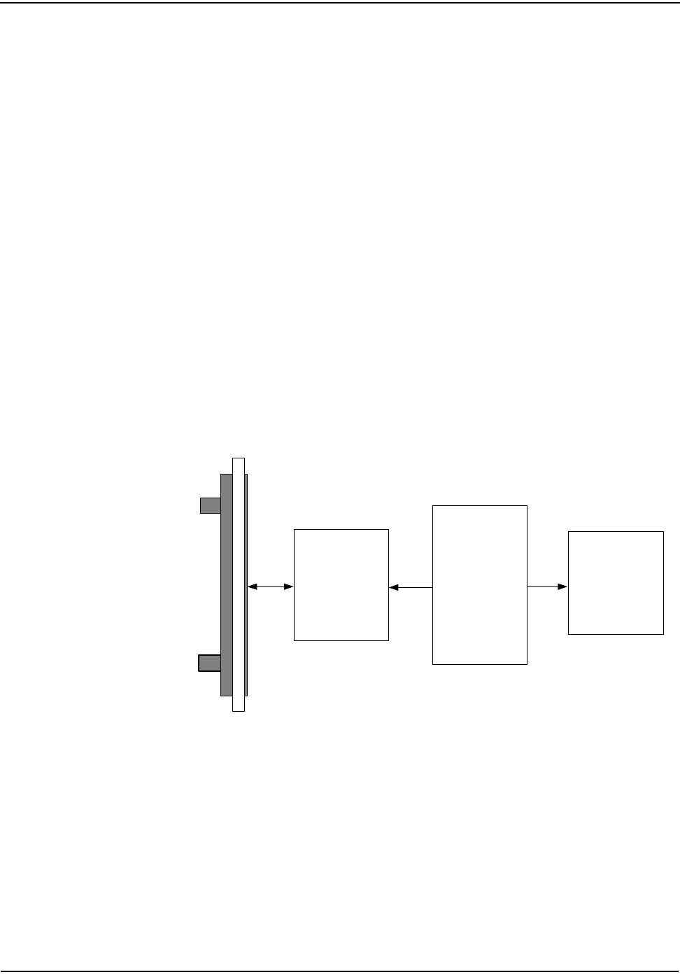
Operation: C1SD, C1ST, and C1SL Versions
5-28 CENTRON Meter Technical Reference Guide
The kWh value broadcast in its SCM shall have six (6) significant digits. The
R300CD converts the floating point BCD kW reading extracted from the
CENTRON self read register to a fixed implied decimal with two digits of
resolution to the right of the decimal point (.01 kW). The maximum kW measured
is therefore restricted to 9999.99 kW.
Figure 5.12 on page 5-28 is a block diagram of R300CD hardware. R300CD
hardware consists of two option boards: a control section and RF section. The
control section communicates to the TOU module at rate of once per minute using
the expansion port on the TOU module. The communication speed is fixed at 2400
baud in the control section and uses the SCS protocol. In each of the two SCMs
described, the respective parameter reported is converted to a binary format for
the RF transmission. No register information is saved in the R300CD option
boards. In the instance of a power outage, the option board will update the kW and
kWh values from the self read register upon power restoration.
The R300CD features the Itron patented method of tamper detection that senses
both meter removal and inversion. The removal tamper (RTPR) increments a
counter each time the meter is abruptly removed from a live meter socket. The
tamper counter utilizes a tilt switch to detect when the meter is removed from the
meter socket. The inversion tamper (ITPR) increments a separate counter each
time the meter senses an inversion. The inversion tamper will be incremented
when an inverted status is detected through a closed tilt switch upon power up.
Each of these tamper indications are then transmitted through the radio frequency
transmission.
Figure 5.12 CENTRON TOU Personality Module with R300CD Option
Programming the R300CD Meter
In order for the R300CD meter to operate properly, you must set certain
parameters. Incorrectly set parameters will result in improper operation of the
R300CD.
The R300CD option boards use either a Load Profile (LP) or Time of Use (TOU)
CENTRON personality module. In order for the R300CD to transmit it must have a
kWh register.
Meter Base
RF Board
Control
Board
TOU
Module
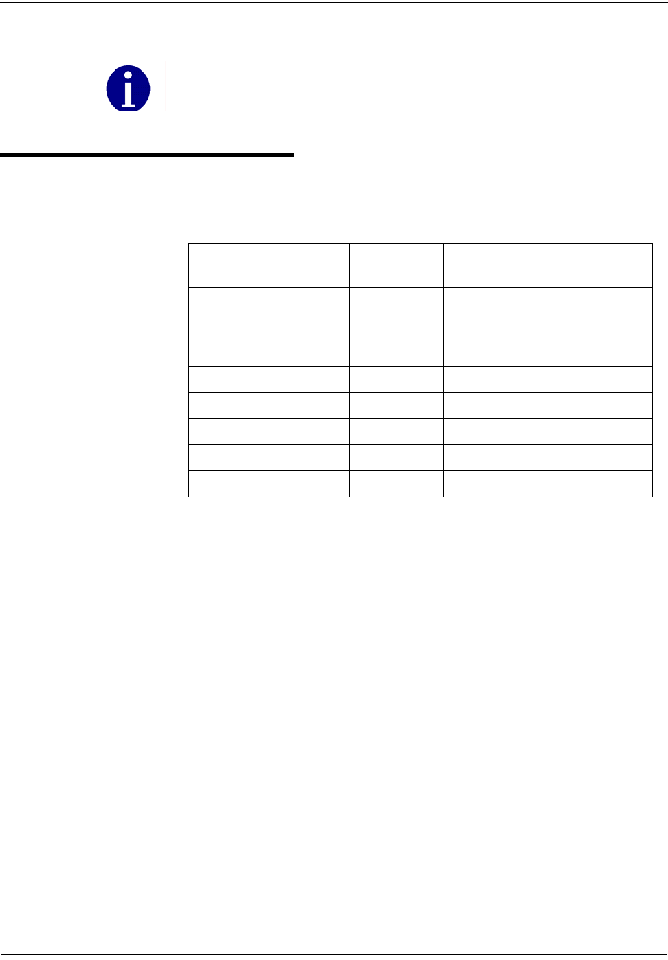
Operation: C1SD, C1ST, and C1SL Versions
CENTRON Meter Technical Reference Guide 5-29
Errors
The table below shows how fatal and non-fatal errors affect R300CD RF
transmission.
The meter will transmit zeros for kWh and kW until it is programmed. For detailed programming
instructions, see the PC-PRO+ documentation. Also refer to the CENTRON R300CD Quick
Install Guide.
Error Error Code Error Type Stops RF
Transmission
Low Battery 000001 Non-Fatal Yes
EEPROM 000010 Fatal Yes
Reverse Direction 007000 Non-Fatal No
Clock 010000 Non-Fatal Yes
Full Scale Overflow 100000 Non-Fatal Yes
TOU Error 020000 Non-Fatal Yes
Load Profile Error 030000 Non-Fatal Yes
Metrology Error 000004 Fatal Yes

Notes:
5-30 CENTRON Meter Technical Reference Guide
Operation: C1SD, C1ST, and C1SL Versions
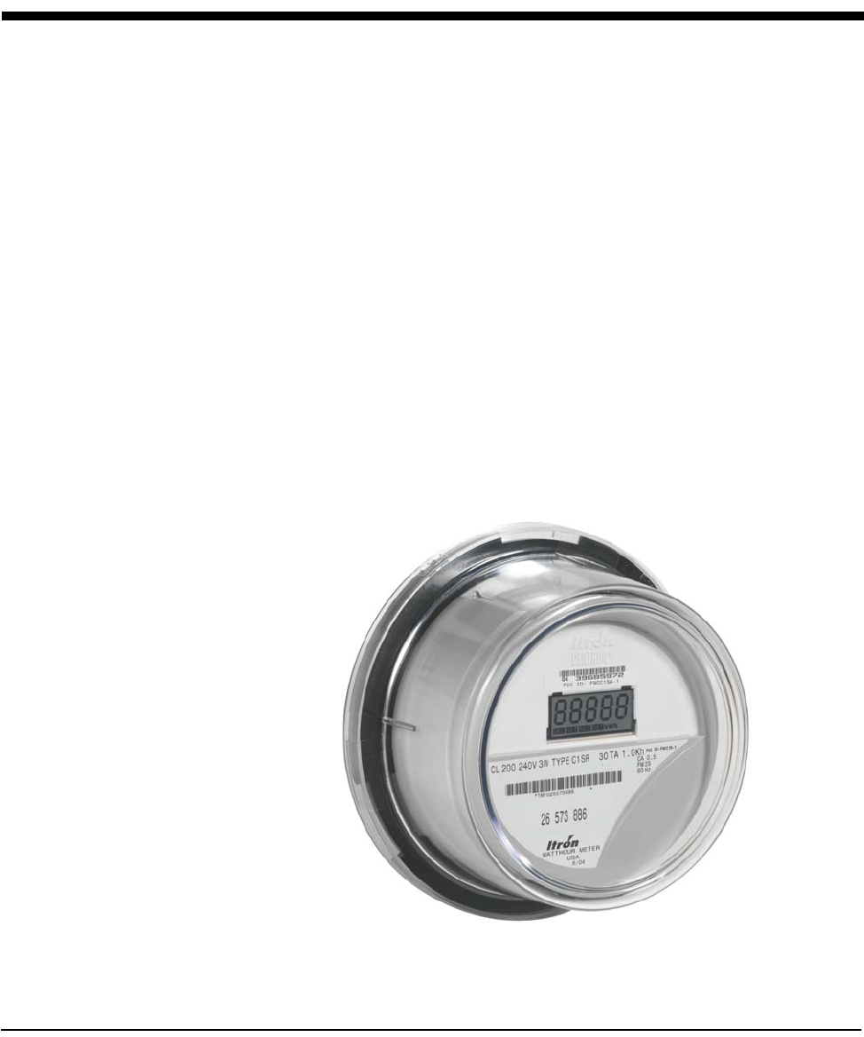
CENTRON Meter Technical Reference Guide 6-1
Chapter 6 Operation: C1SR Version
The Itron CENTRON C1SR is a one-way, unlicensed radio frequency (RF)
personality module that attaches to the CENTRON meter base (See Figure 6.1). It
offers a cost-effective solution for the endpoints in automatic and off-site meter
reading applications. The CENTRON C1SR operates similar to the existing R300
module that is utilized by the J5 electromechanical meter.
Utilizing the 96-bit Itron® Standard Consumption Message protocol (SCM), the
C1SR provides the energy (kWh) consumption, module ID number, tamper
indications, meter type, and error checking information in each radio frequency
transmission. Within the 96-bit SCM, 26 bits are allocated to the module ID number
for meter identification (also referred to as ERT ID number). As of October 15,
1999, all CENTRON C1SR meters utilize 26-bit identification numbers.
The C1SR uses frequency hopping and transmits within the unlicensed 910 to 920
MHz band on an average of once per second. In order to avoid interference from
other devices, the transmission frequencies and time interval between
transmission cycles are completely random in nature.
The C1SR is factory programmed with tuning information, module ID, tamper
indicators (ITPR and RTPR), meter type, energy consumption, and scaling factor.
The program and all register information are stored in non-volatile memory in the
event of a power outage. Upon power restoration, all of the information in the non-
volatile memory is restored to the appropriate registers.
Figure 6.1 C1SR

Operation: C1SR Version
6-2 CENTRON Meter Technical Reference Guide
Physical Description
The C1SR personality module is constructed of a flame retardant printed circuit
board material which supports the discrete, surface-mounted, and integrated
circuit components. A microstrip etched on the circuit board serves as the RF
antenna. The C1SR personality module easily snaps into the meter module
mounting bracket. This module is then electronically attached to the metrology
board via a board to board connector. The following information is sent to the
personality module from the base metrology board:
• Line voltage
• Reference voltage
• Energy flow direction
• Energy pulse data
• Line frequency
The C1SR contains contacts on the module board, located at the 12 o'clock
position behind the LCD, for resetting the energy register and tamper counters.
This can be accomplished with the ZRO-C2A Resetter.
The C1SR uses a unique module identification number, provided by Itron. This ID
number is contained in each message transmission and is used by the handheld
and billing system to determine meter identity and location. This ID number, which
is contained on a bar-coded label, is placed on the LCD housing directly above the
LCD display.
Registers
Display
The C1SR personality module is only available with a liquid crystal display (LCD).
The LCD is automatically adjusted for contrast over the operating temperature
range.
Figure 6.2 C1SR LCD
This module can be configured to display either four or five digits of energy
consumption and will rollover at 100,000 kWh for both self-contained (Form 1S, 2S,
12S, 25S) and transformer rated meters (3S, 4S). The self-contained meters can be
programmed to display normal kWh consumption (5X1 register configuration) or
tens of kWh consumption (4X10 register configuration). If the C1SR is
programmed for a 4x10 display, a “Mult by 10" label is placed on the module to the
left of the LCD display. Thus, the actual energy consumption is obtained by
multiplying the value on LCD display by 10.
Operation: C1SR Version
CENTRON Meter Technical Reference Guide 6-3
The transformer rated meters can be programmed to display either a 5xTR or
4xTR. In order to determine the actual energy consumption, the display reading
needs to be multiplied by the transformer ratio (TR). If the transformer ratio is 1,
then the reading on the display is the actual energy consumption.
The LCD display contains an electronic load indicator (or watt disk emulator). The
disk emulator is three square segments in the lower right-hand corner of the
display, which scroll in the direction of energy flow.
Icons are illuminated on the display when the meter is programmed with a non-
standard algorithm. The LCD will display DET for detented energy. Icons for
delivered (DEL) and received (REC) are not used. There is no additional indicator
for the standard undetented configuration (i.e., where reverse energy is
accumulated in the forward register).
Factory programmable multipliers are available for CL20 (x20, x40 and x80)
applications. This allows the meter to display and transmit via RF primary
readings. Meters are labeled accordingly when factory programmed.
The display will scroll between the billing register and the segment check mode
based on the factory programming option.
Electronic Detent
The C1SR module displays energy in increments of whole values of kWh. Standard
operation for this module is to accumulate both forward and reverse energy flow
in the positive direction. However, the C1SR personality module is available with
an electronic detent that will cause the meter to ignore reverse energy flow.
Therefore, if the meter is inverted, the registers will accumulate in the forward
direction only, thus providing uni-directional operation. At the time of order, the
C1SR module can be selected to have a detent register.
When the meter is undetented, both forward and reverse energy will be
accumulated. Therefore, the electronic load indicator will flash at a rate equal to
the energy consumption, regardless of the direction of the energy flow.
When the electronic detent is enabled, only forward energy flow will be
accumulated. Thus, the disk emulator will not move, nor will the meter accumulate
when reverse energy flow is present.
Net Metering
The C1SR module is available with the option of net metering capability. When the
net option is enabled, received energy is subtracted from delivered energy. The net
energy value is then displayed on the register.
Resetting Values
The ZRO-C2A Resetter zeros both the energy registers and tamper counters by
direct connection to the C1SR module See also The ZRO-C2A Handheld Meter
Resetter for the CENTRON C1S and C1SR Operating Instructions.
Option Description
1 7 second billing register display, 1 second blank, 7 second segment check display (7/7)
2 7 second billing register display, 1 second blank, 1 second segment check display (7/1)
3 Only the billing register is displayed (7/0)
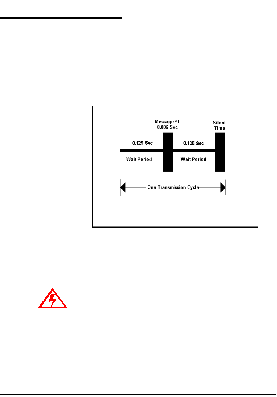
Operation: C1SR Version
6-4 CENTRON Meter Technical Reference Guide
Transmission Scheme
A transmission cycle contains a wait period before and after each message burst
and a period of random silent time. The silent time is determined by the scaling
factor, which sets a minimum and maximum silent time between each
transmission cycle.
The transmission frequencies (within the 910-920 MHz band), the frequency
hopping pattern, and the time interval between transmission cycles are completely
random in nature. This randomness provides a method for avoiding interference
with transmissions from other devices. Figure 6.3 shows an example of the
CENTRON C1SR transmission cycle containing one message burst.
.
Figure 6.3 CENTRON C1SR Transmission Cycle
FCC Regulations
The C1SR communicates in the unlicensed, 910-920 MHz band governed by the US
Code of Federal Regulations (CFR) Title 47, Part 15 Radio Frequency Devices, Sub
Part C Paragraph 249 Intentional Radiator.
Changes or modifications not expressly approved by Itron could void the users authority
to operate the equipment.

Operation: C1SR Version
CENTRON Meter Technical Reference Guide 6-5
Tamper Detection
The CENTRON C1SR features the Itron patented method of tamper detection that
senses both meter removal and meter inversion. The removal tamper (RTPR)
increments a counter each time the meter is abruptly removed from a live meter
socket. The tamper counter utilizes a tilt switch to detect when the meter is
removed from a meter socket.
The inversion tamper (ITPR) increments a separate counter each time the meter
senses reverse power flow caused by meter inversion. The metrology board senses
reverse power flow and sends this status to the C1SR module. Although the C1SR
increments an inversion counter when reverse power flow is detected, the meter,
when undetented, will still accumulate the energy consumption in the positive
direction. Each of these tamper indications, along with the kWh consumption, is
then transmitted through the radio frequency transmission.
Testing the CENTRON C1SR Tamper Counter
In order to test the power removal counter, the meter must sense a shaken
condition associated with a power outage.
1 Place the meter in a socket.
2 Apply power to the meter.
3 Remove the meter from the live socket.
4 Replace the meter in the socket.
The meter has incremented the removal tamper counter.
The C1SR uses the power outage (the meter being removed from a live socket) in
conjunction with the meter being shaken simultaneously to increment the power
removal counter.
In order to test the inversion counter, the meter must sense reverse current flow.
1 Place the meter in the meter socket inverted (test LED pointing down).
2 Apply a load to the meter in the forward direction.
The meter has incremented the inversion counter due to reverse energy flow
through the meter.
The inversion counter increments when the meter senses reverse current flow. The
metrology board senses reverse power flow and sends this status to the C1SR
personality module. The C1SR then increments the counter and transmits the
count.
As part of the 96-bit Standard Consumption Message, 4 bits are allocated for
tamper indications, which include the power removal and meter inversion
counters. The ReadOne® Pro handheld reader converts the 4 bit binary number to
its equivalent value between 0 and 15. Table 6.1 shows the removal and inversion
information based on the reported tamper count. For example, a tamper count of 6
on the ReadOne Pro would translate as 1 meter removal and 2 meter inversions
since the last read.
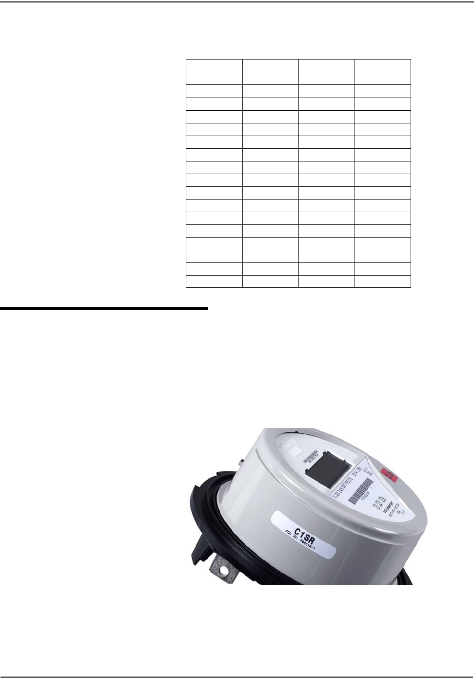
Operation: C1SR Version
6-6 CENTRON Meter Technical Reference Guide
Retrofitting the C1SR Personality Module
The CENTRON R300 is a one-way radio frequency personality module that
transmits within the unlicensed 910-920 MHz frequency band governed by the US
Code of Federal Regulations (CFR) Title 47, Part 15 Radio Frequency Devices, Sub
Part C Paragraph 249 Intentional Radiator. Any device operating within this
unlicensed frequency band must contain an FCC Identification number. Therefore,
the FCC ID Label included in the Retrofit Kits must be placed on the meter as
shown below.
Figure 6.4 C1SR FCC Label Location
Table 6.1 ReadOne Pro Tamper Count
Binary Tamper
Count Inversion Removal
0000 0 0 0
0001 1 1 0
0010 2 2 0
0011 3 3 0
0100 4 0 1
0101 5 1 1
0110621
0111 7 3 1
1000 8 0 2
1001 9 1 2
1010 10 2 2
1011 11 3 2
1100 12 0 3
1101 13 1 3
1110 14 2 3
1111 15 3 3

Operation: C1SR Version
CENTRON Meter Technical Reference Guide 6-7
To retrofit an existing meter with an R300 module, follow "Retrofitting with
Personality Modules" on page 2-3.
Changes or modifications not expressly approved by Itron could void the user's authority to
operate the equipment.

Notes:
6-8 CENTRON Meter Technical Reference Guide
Operation: C1SR Version
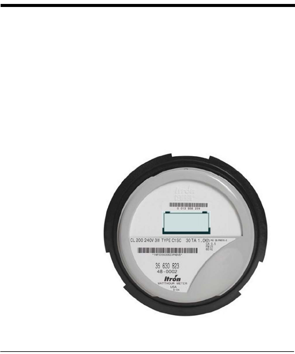
CENTRON Meter Technical Reference Guide 7-1
Chapter 7 Operation: C1SC Version
The Itron C1SC is a one-way transmitter used for the CellNet fixed network
technology. The personality module transmits a formatted data packet consisting
of the preamble, the utility billing ID, kWh information, and Cyclic Redundancy
Checks (CRC) to ensure message integrity. The module also features built in power
outage notification, reverse power flow detection, power restoration notification,
and redundant transmissions. The C1SC uses spread spectrum to broadcast its
message in the 902 to 928 MHz frequency range once every five minutes.
The C1SC is factory programmed to include the utility billing ID, LAN Address ID,
and Register configuration. The utility billing ID is a value decided upon by the
utility and CellNet. The LAN address is a value that is assigned by Itron and
programmed into every meter within the network. LAN addresses and utility billing
IDs are unique to each meter. Itron activates the LAN ID upon receipt of the meter
association file.
After programming, the module is tested to verify the operating system parameters
and FCC compliance. A final test is performed via RF to verify a correct LAN
address meter ID number of digits and RF signal.
Figure 7.1 C1SC

Operation: C1SC Version
7-2 CENTRON Meter Technical Reference Guide
Physical Description
The C1SC is constructed of a flame retardant, glass-filled printed circuit board
material which supports the discrete, surface-mounted, and integrated circuitry
components. A slot antenna etched on the circuit board serves as the RF antenna.
The C1SC board snaps into the meter register mounting brackets to ease in the
installation of the board. The LAN address barcode and interpretation is placed on
the LCD housing for meter identification.
The C1SC personality module is attached to the metrology board using a board to
board connector. The following information is passed from the metrology board to
the C1SC:
• Line Voltage
• Reference Voltage
• Energy Flow direction
• Energy pulse data
• Line frequency
The C1SC has two additional labels called the meter change-out labels that are
affixed to the bottom of the meter. The change out labels are identical and contain
the AEP barcode information and a utility descriptor.
Transmission Scheme
The RF transmission is spread spectrum using Binary Phase Shift Keyed (BPSK)
modulation. A chipping signal is used to spread the carrier and actual data is on-
off-keyed (OOK). The modulator output drives the amplifier chain that provides a
signal of approximately 100mW. The antenna is tuned for maximum efficiency at
the carrier frequency.
Figure 7.2 shows how messages are typically transmitted. In the example, an
interval packet made up of 18 intervals is transmitted every five minutes. Each
interval contains a pulse count equivalent to the energy consumption for a 2.5
minute interval. The interval packet transmission represents a sliding 45 minute
window of data.
Also shown in Figure 7.2, Interval packet 0 shows that the 2.5 minute interval is
transmitted in one of the 18 packets of 2.5 minute information. Interval packet 1 is
transmitted 5 minutes later and the selected 2.5 minute interval of data is now
transmitted as the 16th packet (numbered 15). The following packet slides the
information by two 2.5 minute intervals and continues for a total of nine
transmissions. The information is then no longer in the sliding 45 minute window.
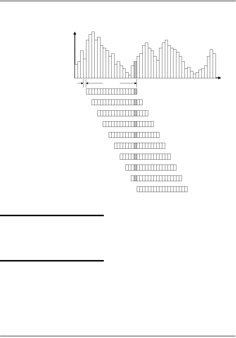
Operation: C1SC Version
CENTRON Meter Technical Reference Guide 7-3
Figure 7.2 CellNet Telemetry
FCC Regulations
The C1SC communicates in the unlicensed 902-928 MHz band governed by the US
Code of Federal Regulations (CFR) Title 47, Part 15, Subpart C, Paragraph 247.
This device complies with Title 47, Part 15, Subpart C, Paragraph 247 of the FCC
rules.
Display Functions
The LCD is configured for five digits of energy consumption and will rollover at
100,000 kWh. The LCD is automatically adjusted for contrast over the operating
temperature range.
A watt disk emulator is located on the lower right hand corner of the display. The
indicator consists of three square segments in the lower right-hand corner of the
display, which scroll in the direction of energy flow. Figure 7.3 below illustrates
this revision.
0
1
0
1
Time
kWh
(Pulses)
01234567891
01
11
21
31
41
51
6
Interval 0
Interval 1
Interval 2
Interval 3
Interval 4
Interval 5
Interval 6
Interval 7
Interval 8
Interval 9
1
7
45 minutes
2.5 minutes
(Interval
Resolution)
Interval packets contain 18 intervals
Intervals close every 2.5 minutes
Endpoints transmit approx. every 5 minutes
Transmissions are randomized over 5 minute period.
Each interval is transmitted nine times, thus nine times the redundency.
C
ELL
N
ET
E
LECTRICITY
I
NTERVAL
T
ELEMETRY
0 1 2 3 4 5 6 7 8 9 1
01
11
21
31
41
51
61
7
01234567891
01
11
21
31
41
51
61
7
01234567891
01
11
21
31
41
51
61
7
01234567891
01
11
21
31
41
51
61
7
01234567891
01
11
21
31
41
51
61
7
01234567891
01
11
21
31
41
51
61
7
01234567891
01
11
21
31
41
51
61
7
01234567891
01
11
21
31
41
51
61
7
01234567891
01
11
21
31
41
51
61
7
0
1
0
1
Time
kWh
(Pulses)
01234567891
01
11
21
31
41
51
6
Interval 0
Interval 1
Interval 2
Interval 3
Interval 4
Interval 5
Interval 6
Interval 7
Interval 8
Interval 9
1
7
45 minutes
2.5 minutes
(Interval
Resolution)
Interval packets contain 18 intervals
Intervals close every 2.5 minutes
Endpoints transmit approx. every 5 minutes
Transmissions are randomized over 5 minute period.
Each interval is transmitted nine times, thus nine times the redundency.
C
ELL
N
ET
E
LECTRICITY
I
NTERVAL
T
ELEMETRY
0 1 2 3 4 5 6 7 8 9 1
01
11
21
31
41
51
61
7
01234567891
01
11
21
31
41
51
61
7
01234567891
01
11
21
31
41
51
61
7
01234567891
01
11
21
31
41
51
61
7
01234567891
01
11
21
31
41
51
61
7
01234567891
01
11
21
31
41
51
61
7
01234567891
01
11
21
31
41
51
61
7
01234567891
01
11
21
31
41
51
61
7
01234567891
01
11
21
31
41
51
61
7
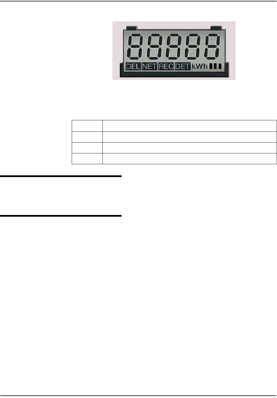
Operation: C1SC Version
7-4 CENTRON Meter Technical Reference Guide
Figure 7.3 C1SC LCD
The display will scroll between the billing register and the segment check mode
based on the factory programming option.
Resetting Values
The C1SC can be reset using the CellNet Shooter device in conjunction with a
computer.
Programming the C1SC/CN1SC
The CENTRON C1SC/CN1SC CellNet personality module programming port is
located such that the CENTRON inner cover does not have to be removed when
programming or testing the CellNet module.
In order to communicate with the CENTRON CellNet module, insert the
programming slide into the hole in the inner cover of the CENTRON meter that is
located at the 12 o’clock position (see Figure 7.4).
Option Description
1 7 second billing register display, 1 second blank, 7 second segment check display (7/7)
2 7 second billing register display, 1 second blank, 1 second segment check display (7/1)
3 Only the billing register is displayed (7/0)
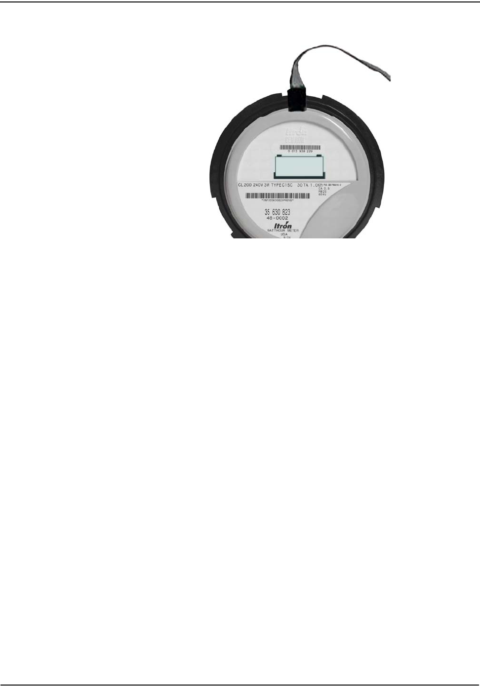
Operation: C1SC Version
CENTRON Meter Technical Reference Guide 7-5
Figure 7.4 C1SC/CN1SC Programming Port Location

Notes:
7-6 CENTRON Meter Technical Reference Guide
Operation: C1SC Version
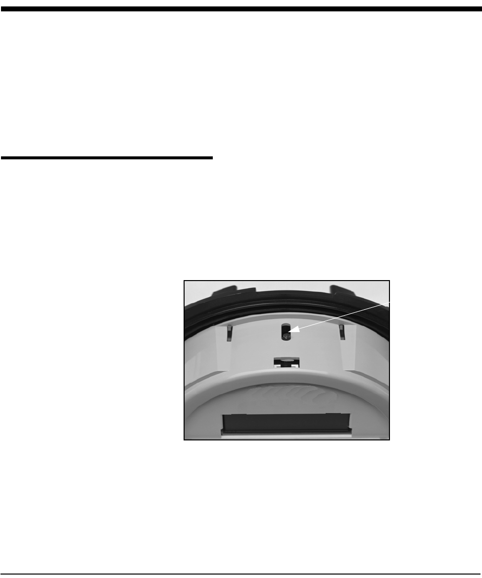
CENTRON Meter Technical Reference Guide 8-1
Chapter 8 Testing, Troubleshooting, and Maintenance
This section provides information and instructions to help you test and maintain
the CENTRON meter. Topics covered include:
• Testing support features
• Energy testing
• Recommended testing procedures
• TOU schedule testing
• Field testing
• Troubleshooting (Fatal and non-fatal errors)
• Maintenance
Testing Support Features
Infrared Test LED
The CENTRON meter is equipped with an Infrared Test Light Emitting Diode
(LED) where each pulse represents a fixed value of watthour measurement. The
LED is located on the top of the meter as the meter is viewed from a typical
installation (see Figure 8.1). The pulse weight represented by the LED pulses is 1.0
watthour per pulse (Kh=1.0).
Figure 8.1 LED Location
Pulse Detector
An optional pulse detector is available for the CENTRON meter. The pulse detector
has an infrared pickup with two visible LEDs. When positioned over the
CENTRON light pipe, it will produce a visible flash when an infrared pulse is
received from the metrology. The right LED will flash once for each infrared Wh
Test Led
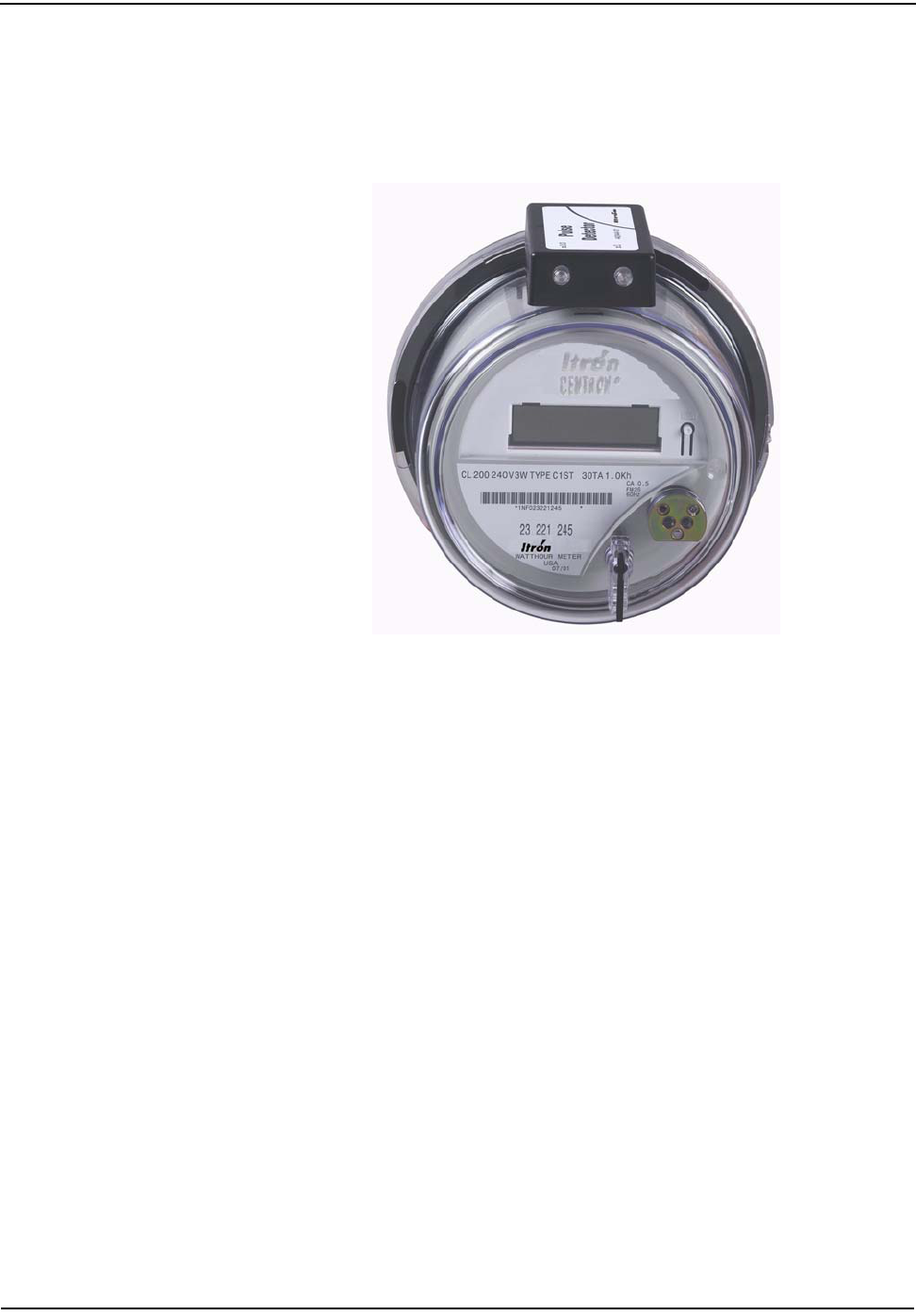
Testing, Troubleshooting, and Maintenance
8-2 CENTRON Meter Technical Reference Guide
pulse while the left LED will flash once for every 10Wh infrared pulses received.
The left LED on the pulse detector is helpful when heavier loads are present on the
system being examined. This can be used to verify that the metrology is measuring
energy when installed and to conduct timing tests to determine the amount of load
on meter.
Figure 8.2 Pulse Detector
Annunciators
Watthour Annunciators
C1SR meters (and some C1S versions) are equipped with LCD displays that utilize
a single flashing triangular annunciator to show that power is being metered. The
annunciator represents 1.0 watthour each time it turns on and 1.0 watthour each
time it turns off for a total of 2.0 watthours.
On other CENTRON meters equipped with LCD's, there are three such
annunciators which also show the direction of energy flow (C1S, C1SC, C1SD,
C1ST, C1SL). The triangles will scroll left to right for positive (line to load) energy
flow, and right to left for negative energy flow.
The Kh value of the single triangle is twice the Kh of the LED and, therefore, 2.0
watthours per pulse. On the three triangle units the Kh of each triangle is further
multiplied by three as each triangle is turned on and off in sequence, resulting on a
Kh of 6.0.
TOU Rate Annunciators
The CENTRON meter is equipped with five Time-of-Use annunciators on the LCD
(see Figure 8.3). Located on the right side of the display, the annunciator A, B, C, D,
or TOTAL flashes when the applicable rate is active and is enabled to display their
respective values. (Available on the C1ST and C1SL.)
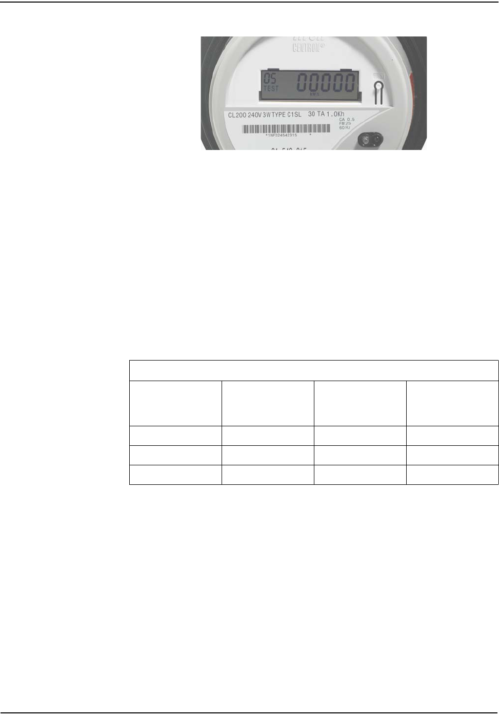
Testing, Troubleshooting, and Maintenance
CENTRON Meter Technical Reference Guide 8-3
Figure 8.3 TOU Rate Annunciators
Test Mode Annunciator
The CENTRON meter is equipped with a Test Mode LCD annunciator located in
the left portion of the display. This annunciator is enabled when Test Mode is
activated. The word TEST appears on the display and flashes at a steady rate when
test mode is activated. (Available on the C1SD, C1ST, and C1SL.)
Testing with the Infrared Test LED
The CENTRON meter is equipped with an Infrared Test LED (Light Emitting
Diode) which is located on the top of the meter at the 12 o’clock position.
The pulse weight represented by the LED pulses is always 1.0 watt-hour per pulse.
Since the Kh value for the meter is 1.0, make sure the test board is programmed to
accept this Kh value.
1 pulse = 1 Watt-hour as compared to 1 pulse = 7.2 Watt-hours in
Electromechanical meters.
To obtain test uncertainties of 0.01% (plus the uncertainties of the test equipment),
use a minimum of 30 pulses.With a constant load applied (real or phantom), the
LED pulses are compared to the output of a high accuracy watthour standard. This
is accomplished using a compatible optical pickup and a comparator.
Follow these steps to test the Wh LED:
1 Apply a constant delivered watts load (Wapp) to the meter.
2 Verify that the LED pulses properly either by counting the pulses or using a
comparator to compare the pulses from the meter under test to the standard.
# OF PULSES REQUIRED ON TEST BOARDS
1S & 2S CL200 120V 3S,
240V 3S,
240V 4S
12S & 25S, 2S
CL 320
Full Load 10 7 15
Light Load 10 6 7
Power Factor 10 7 12

Testing, Troubleshooting, and Maintenance
8-4 CENTRON Meter Technical Reference Guide
To determine the number of pulses per second, use the following equation:
Testing Using the Disk Emulation Annunciator
The CENTRON meter is capable of visually being tested by using the Watt Disk
Emulation Annunciator.
Recommended Energy Testing Procedures
Testing solid-state meters on test boards that were designed primarily for
electromechanical meters may give unexpected results. Erroneous readings have
been known to occur on “light load” tests when the test sequence calls for said
light load test to follow immediately after the full load test. The problem is caused
by improper “jogging” and can be avoided by sequencing the test in order of
applied power such that the lowest power is tested first. This problem does not
exist on modern test boards with the latest test software.
AEP Test Codes
Table 8.1 shows the AEP Test Codes.
Field Testing
Field testing of the CENTRON meter may be accomplished with conventional
methods using either the infrared test LED or the disk emulation annunciator
(when supplied). For details on the operation of the annunciator, see Page 8-2.
Required Hardware
The typical field test setup consists of a phantom load, portable standard, and an
infrared test pulse adapter with a counter or snap switch assembly. CENTRON
meters purchased without a test link will require a more sophisticated loading
circuit.
Number of Pulses per sec Wapp 1hr
3600
-------------1Kh××=
Tab le 8.1 AEP Te st Co des
Meter Specification Code
CL100 120V 2W 1 Phase Type C1S 15TA 1.0Kh FM1S 60Hz 2B
CL200 240V 3W 1 Phase Type C1S 30TA 1.0Kh FM2S 60Hz 1N
CL320 240V 3W 1 Phase Type C1S 50TA 1.0Kh FM2S 60Hz 2J
CL20 240V 2W 1 Phase Type C1S 2.5TA 1.0Kh FM3S 60Hz 2F
CL20 120V 2W 1 Phase Type C1S 2.5TA 1.0Kh FM3S 60Hz 2E
CL20 240V 3W 1 Phase Type C1S 2.5TA 1.0Kh FM4S 60Hz 2G
CL200 120V 3W 2 Phase Type CN1S 30TA 1.0Kh FM12S
60Hz 2H
CL200 120V 3W 2 Phase Type CN1S 30TA 1.0Kh FM25S
60Hz 2I

Testing, Troubleshooting, and Maintenance
CENTRON Meter Technical Reference Guide 8-5
Troubleshooting
Error Codes (R300)
Non-Fatal Error
Fatal Error
Error Codes (Demand, TOU, and Load Profile)
The firmware performs error checks to confirm proper register operation. Table
8.2 lists possible errors and associated error codes.
Fatal errors cause the display to lock on the error code. If multiple fatal errors
occur, the one that was detected first will be the error code that locks on the
display.
Cause Effect Indication
Checksum Error of the
Energy Register
Stops RF transmission but
continues energy
accumulation and will be
cleared after a power cycle.
The LCD will display the
annunciator, a downward
pointing arrow, in the lower
right hand corner.
Cause Effect Indication
Unsuccessful writing to or
reading from EEPROM
memory.
All metering and RF functions
are halted. Return the module
to the factory for repair.
The LCD will display the word
Error in the area normally
used for energy
accumulation.
Metrology error.
All metering and RF functions
are halted. Return the meter
and module to the factory for
repair.
The LCD will display the word
Error in the area normally
used for energy
accumulation.
Table 8.2 Error Codes
Error Error Code Error Type
Low Battery Er 000001 Non-fatal
EEPROM Er 000010 Fatal
Reverse Direction Er 007000 Non-fatal
Clock Er 010000 Non-fatal
Full Scale Overflow Er 100000 Non-fatal
TOU Error Er 020000 Non-fatal
Load Profile Error Er 030000 Non-fatal
Metrology Error Er 000004 Fatal
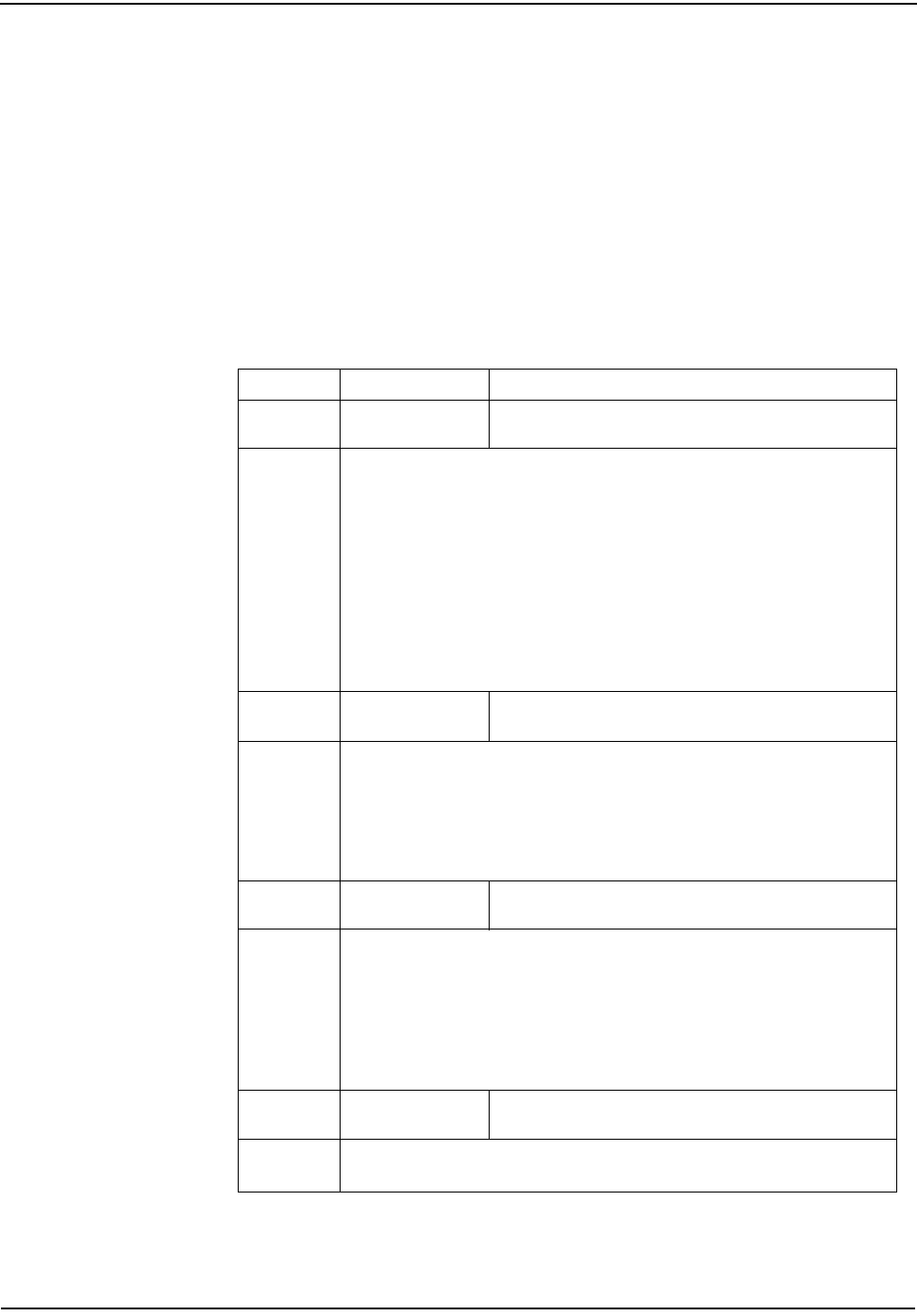
Testing, Troubleshooting, and Maintenance
8-6 CENTRON Meter Technical Reference Guide
Non-fatal errors can be programmed to scroll during the one second display off-
time or lock on the register display. If multiple non-fatal errors occur, the meter
will display a combined error message. For example, if a low battery error and a
clock error exist, the error display will read ER 010001. In this case, if one of the
errors had been programmed to lock, and the other error had been programmed to
scroll, the display will lock on the combined error message.
Activating the Alternate Mode Magnetic Reed Switch allows the Normal Mode
Display Sequence to scroll one time during a locked non-fatal error. At the end of
the display sequence, the error message locks onto the display again.
Non-Fatal Error Codes
Table 8.3 Non-Fatal Error Codes
Code Error Possible Causes
Er 000001 Low Battery Error Number of minutes on the battery has exceeded one year—
checked on power up and once per second.
Discussion:
A low battery check is performed once every second. If a low battery level is detected
during this procedure, error code Er 000001 is displayed in Normal mode. This error can
be programmed to continuously scroll during the one second display off-time or lock on
the register display. A low battery continues to function; however, its reliability decreases
over time.
If a low battery level error occurs during normal operation, TOU and Mass Memory will
continue to operate until an outage occurs. If a low battery level is detected upon
programming or upon restoration of power after an outage, ER 000001 will display. Total
registers remain functional during a Low Battery Condition; however, TOU (rates A, B,
C, D) registers and load profile will not accumulate.
Er 007000 Reverse Direction
Error Reverse Direction Error Indicator—Clear on demand reset or
reprogram register; checked continuously.
Discussion:
A Reverse Direction error exists when the register detects 10 Wh in the reverse
direction. Reverse Direction detection is a selected feature during programming. If a
Reverse Direction error occurs, Er 007000 is displayed during the one second off-time
in Normal mode.
The Reverse Direction error will clear when a demand reset is performed.
Er 010000 Clock Error Clock Error—Reprogram register and check for proper
operation; checked upon programming and once per second
Discussion:
A Clock error exists when a clock parameter is determined to be out of range. If this
error occurs, Er 010000 is displayed in Normal mode. This error is programmable to
continuously scroll during the one second display off-time or lock on the register display.
If a Clock error occurs, the Load Profile and TOU operations will be discontinued until
the meter is reprogrammed. The error will then clear, and the meter will resume normal
operation.
Er 020000 TOU Error TOU Error—Reprogram register and check for proper
operation; checked upon programming and once per second
Discussion:
A TOU error occurs when the TOU calendar is out of range. TOU is disabled.
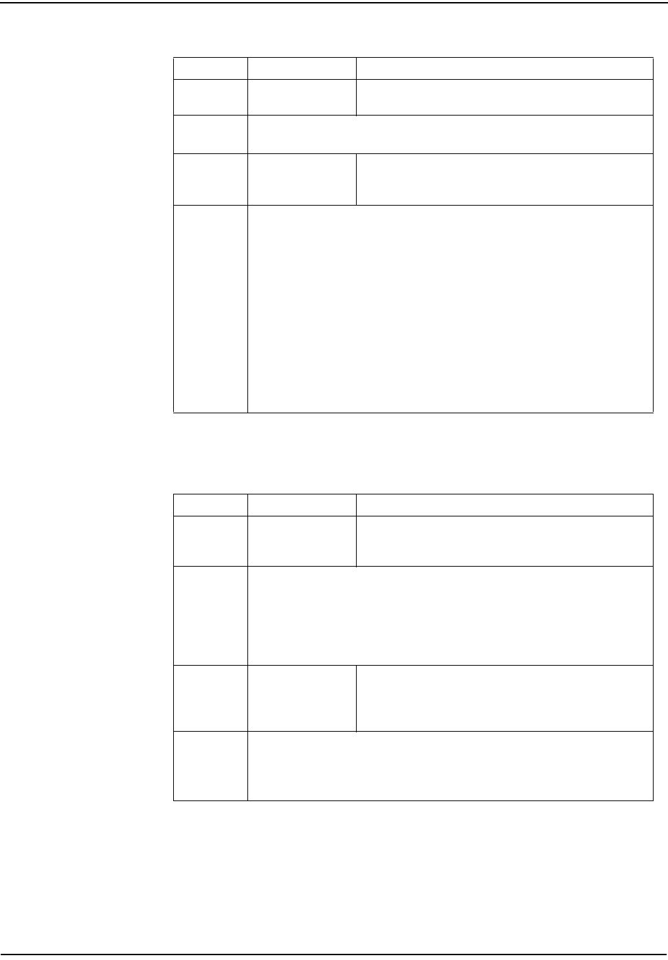
Testing, Troubleshooting, and Maintenance
CENTRON Meter Technical Reference Guide 8-7
Fatal Error Codes
Er 030000 Load Profile Error Load Profile Error—Reprogram register and check for proper
operation; checked upon programming and once per second
Discussion:
A Load Profile error occurs when the Load Profile parameter is out of range or inactive.
Er 100000 Full Scale Overflow
Error
Programmed Full Scale Value exceeded—Check programmed
Full-Scale value and meter installation for proper sizing of
equipment; checked continuously.
Discussion:
A Full Scale overflow error exists when the calculated demand at an EOI exceeds the
register Full Scale value. The register Full Scale value is selected during programming.
If an overflow occurs, the error code Er 100000 is displayed in Normal mode. This error
is programmable to display during the one second display off-time or lock on the register
display.
The Full Scale overflow error displays when the overflow occurred. The Maximum
Demand register continues to accumulate and display kW as long as the format
limitations are not exceeded. When a demand reset is performed, the correct Max kW
value will be added to the cumulative registers and the error code will no longer be
displayed. If a Full Scale overflow occurs, check the installation to ensure that the
current metering capability has not been exceeded. A Full Scale overflow in no way
affects the existing billing data.
Table 8.4 Fatal Error Codes
Code Error Possible Causes
Er 000004 Metrology Error (Available in firmware revisions 10.27 and above.) Defective
component in the base metrology causing invalid energy pulse
signal.
Discussion:
The direction of energy flow signal is monitored for rate of change. If the rate of change
exceeds 14 Hz, the metrology error is triggered. Under this condition the base metrology
has become defective and the energy pulse signal being sent from metrology to the
D/T/L module is no longer valid. Base metrology should be replaced in the event of this
error.
Er 000010 EEPROM Error
Energy value checksum failure; EEPROM failure—reprogram
module and check for proper operation. If error still does not
clear, replace module; checked upon programming and at
power up.
Discussion:
If the module has an EEPROM error, the error code ER 000010 will be continuously
displayed. If this error occurs, program the module and check for proper operation. If the
error continues to exist, replace the module.
Table 8.3 Non-Fatal Error Codes
Code Error Possible Causes
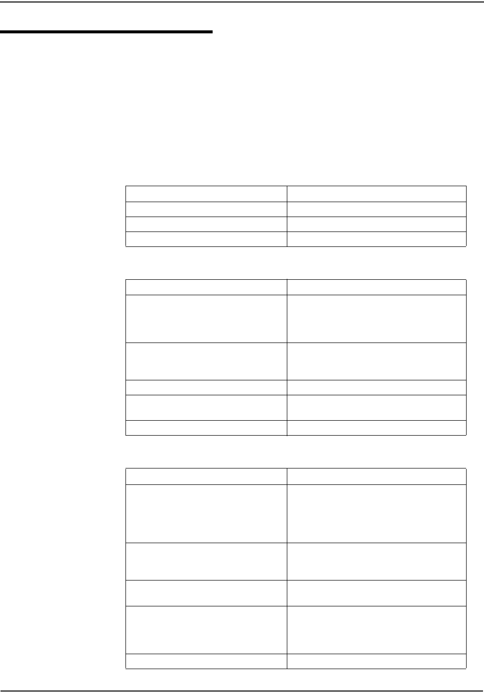
Testing, Troubleshooting, and Maintenance
8-8 CENTRON Meter Technical Reference Guide
Inspecting and Troubleshooting—General
Due to the modular architecture of the CENTRON meter, modules of similar
voltage (120V or 240V) may be interchanged. Therefore, the personality module of
the CENTRON you are troubleshooting can be placed on a known working base to
verify proper operation of the personality module. Likewise, a known working
personality module may be placed on the base of a meter to verify proper
operation of the meter.
This section provides a list of the most likely problems that you may encounter,
along with possible causes and solutions.
Blank Display
Time and Date Wrong (TOU or Load Profile Only)
No Accumulation of kWh or kW
Cause Solution
Power Not Applied to Meter Apply power.
LCD/LCD Driver Failure Replace Register Circuit Board.
Loose Power Supply Connection Remove and re-seat board-to-board connector.
Cause Solution
Time/Date Wrong in PC or Handheld device
Verify and update time/date in programming device
and download new time and date to register. See
appropriate software manual for more detailed
directions.
Wrong Line Frequency Verify proper line frequency is selected in Setup
routine in programming software. Select proper
frequency and reconfigure meter.
Battery Failure During Power Outage Replace module.
Daylight Savings Time not Programmed
Correctly Verify DST is selected in program. Reconfigure
meter with correct program.
Timekeeping circuitry component failure Replace module.
Cause Solution
Demand Delay Selected
kW will not immediately accumulate after a power
outage if CLPU (Demand Delay) has been selected.
Accumulation will begin immediately after Demand
Delay has expired. Verify register program and
reconfigure meter.
Module was left in Test mode Accumulation of kW or kWh will not take place while
register is in Test mode. Exit Test mode and verify
proper accumulation begins.
Module Not Receiving Pulses Verify that meter is accumulating energy by testing
infrared test LED.
Time-of-Use Schedule programmed
incorrectly
Verify TOU schedule contains continuous 24-hour
periods for all weekdays, weekends, or holidays. All
24-hour periods throughout every year must be
accounted for within the TOU schedule.
Component Failure Replace module.
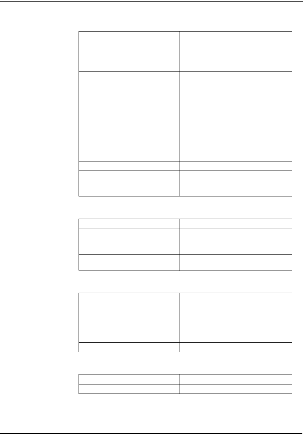
Testing, Troubleshooting, and Maintenance
CENTRON Meter Technical Reference Guide 8-9
Software Cannot Communicate with Module
Reed Switch Does Not Activate the Alternate Mode
Reset Mechanism Does Not Initiate Demand Reset
Demand Reset Cannot be Initiated Through PC or Handheld
Cause Solution
Optical Probe Cable Assembly Failure
Check cable with known register that
communicates. Check cable against known cable
that is functioning. Also check batteries in cable
assembly.
Com Port in PC is Set Wrong Verify proper Com Port number has been selected
in the programming software. If the wrong Com Port
is selected, communications will not occur.
Security code in Module
If security codes have been downloaded to the
register, the programming device must have the
proper code to make connection to the module.
Verify security codes in the programming software.
Probe Not Connected Properly
Verify Optical Probe lines up properly over the
optical connector. Re-install cover for proper
alignment. Verify PC or handheld and cable are
securely connected and attached to the correct Com
Port.
Optical Connector Failure Replace cover assembly.
Electronics Failure Replace module.
Incorrect Baud Rate Optical port can be programmed to operate at 4800
or 9600 baud. Factory default baud rate is 4800.
Cause Solution
Magnetic Field is too Weak Place magnet closer to switch or use stronger
magnet.
Reed Switch Failure Replace module.
Alternate Mode Items Not Selected Re-program meter with items to be displayed in
Alternate mode.
Cause Solution
Reset Mechanism Does Not
Initiate Demand Reset Re-install or Replace cover assembly.
Reset Has Occurred Within Last 60 Seconds Manual demand reset cannot occur within 60
seconds of the previous demand reset. Wait 60
seconds and perform a second Demand Reset.
Reset Button Is Defective Replace module.
Cause Solution
Communication Cannot Be Established See Programming Problems.
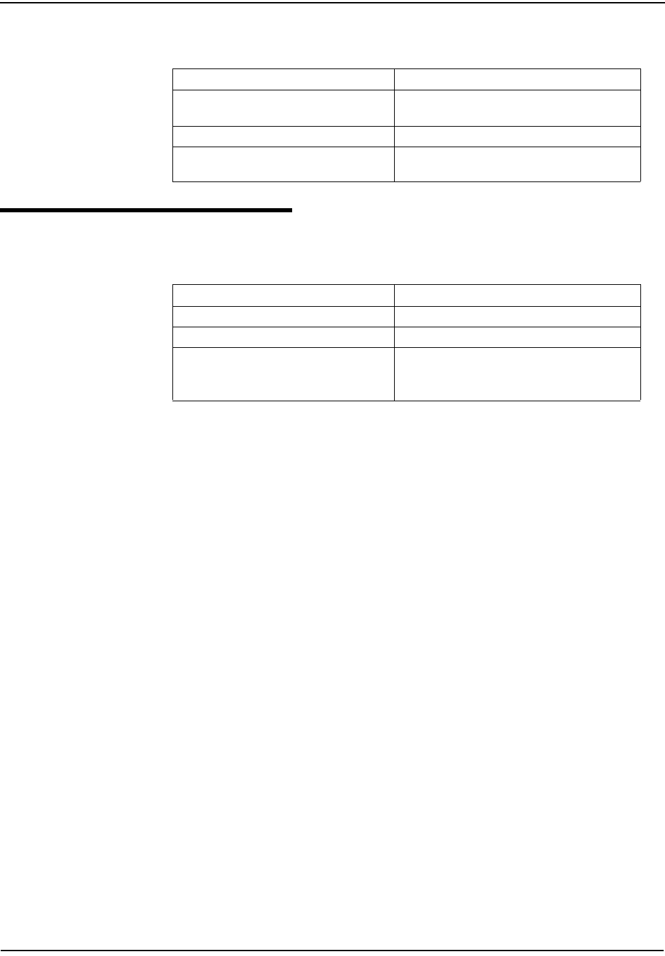
Testing, Troubleshooting, and Maintenance
8-10 CENTRON Meter Technical Reference Guide
Test Mode Switch Does Not Place Module in Test Mode
Inspecting and Troubleshooting—C1S LCD and C1SR
Blank Display
Cause Solution
Switch Not Fully Depressed Verify that the test mode pushbutton has been
completely depressed.
Switch or Electronic Failure Replace module.
Test Mode Items Not Selected Re-program module with items to be displayed in
Test mode.
Cause Solution
Power not applied to the meter Apply power.
Loose power supply connection Remove and re-seat board to board connector.
LCD/LCD Driver failure Replace Register circuit board.
Note: Energy reading and tamper flags may be
uploaded with the ZRO-C2A.
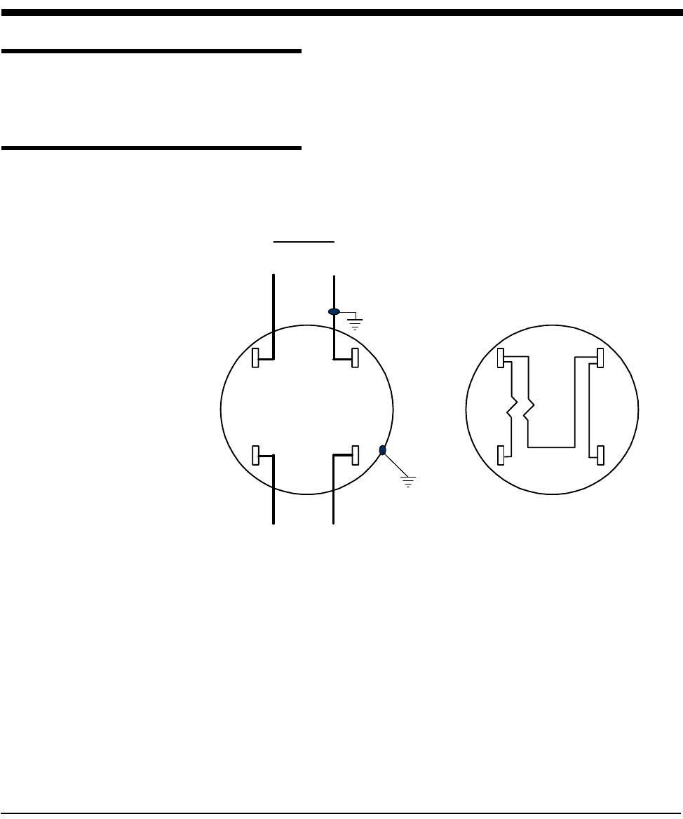
CENTRON Meter Technical Reference Guide 9-1
Chapter 9 Specifications and Drawings
Specifications
For a complete list of the latest CENTRON specification numbers, refer to the
CENTRON Meter Specification Numbers Bulletin, Part Number 428601-220.
Drawings
Figure 9.1 Form 1S Wiring Diagram
1
10
0
10
LINE
++
LOAD

Specifications and Drawings
9-2 CENTRON Meter Technical Reference Guide
Figure 9.2 Form 2S Wiring Diagram
Figure 9.3 Form 3S Wiring Diagram
1
102
02
102
LINE
LOAD
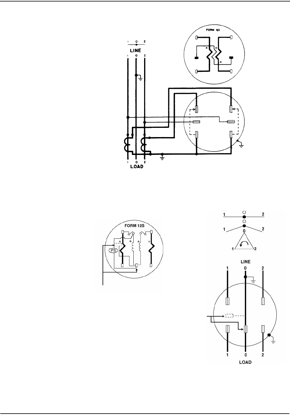
Specifications and Drawings
CENTRON Meter Technical Reference Guide 9-3
Figure 9.4 Form 4S Wiring Diagram
Figure 9.5 Form 12S Wiring Diagram
Alternate
positions of
fifth
jaw
terminal
Alternate positions
of movable potential
terminal
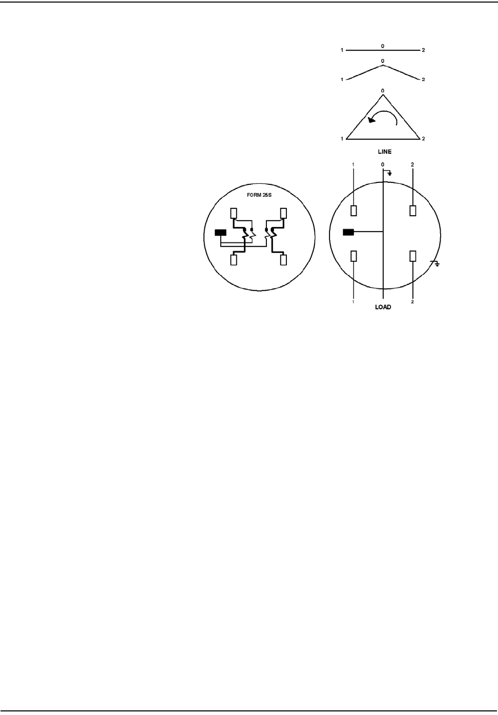
Specifications and Drawings
9-4 CENTRON Meter Technical Reference Guide
Figure 9.6 Form 25S Wiring Diagram

CENTRON Meter Technical Reference Guide G-1
Term Description
annunciator A Liquid Crystal Display (LCD) label that is displayed to identify a particular
quantity being displayed
baud Unit of data transmission signalling speed, roughly analogous to bits per second
(bps)
display duration The programmed number of seconds that a quantity is displayed on the LCD before
it is replaced with the next quantity in the display sequence
EEPROM Electrically Erasable Programmable Read Only Memory. A memory chip that can
only be erased by an electrical signal (retains data during a power outage)
EPROM Erasable Programmable Read Only Memory. Similar to EEPROM except it requires
ultraviolet light to be erased
electronic detent An algorithm in firmware which restricts the device to metering energy flow only to
the customer (unidirectional metering)
firmware Computer programs stored in non-volatile memory chips (ROMs, PROMs, EPROMs,
EEPROMs, etc.)
fixed decimal A display format that always retains the same number of digits to the right of the
decimal point
floating decimal A display format that allows a maximum number of digits to the right of the
decimal, but can display any number of digits to the right of the decimal equal to or
less than that number specified
LCD Liquid Crystal Display
LED Light-Emitting Diode
magnetic reed switch A mechanical switch consisting of a thin metal contact which is closed by an
external magnetic field
nonvolatile memory See EEPROM
RS-232 A communication media whereby information is transmitted through a serial bit
stream
GLOSSARY

Glossary
G-2 CENTRON Meter Technical Reference Guide
Notes:

CENTRON Meter Technical Reference Guide I-1
A
ADC 3-2, 3-4
AEP barcode 7-2
AEP test codes 8-4
alternate display mode 5-3
Alternate mode annunciator 5-5
Alternate Mode Magnetic Reed Switch 8-6
analog to digital converter (ADC) 3-2
annunciator 2-2, 5-5, 8-2–8-3, G-1
Alternate mode 5-5
disk emulator 8-4
EOI 5-6
kWh 5-6
Test 5-4
test mode 5-5
antenna
RF 6-2, 7-2
Application Specific Integrated Circuit (ASIC) 3-2
ASIC 3-2–3-3
automatic demand reset 5-8
B
barcode
AEP 7-2
LAN address 7-2
base 1-2
base metrology 3-1
battery 1-4, 5-23
life 5-23
baud G-1
billing quantities 5-7
Binary Phase Shift Keyed (BPSK) modulation 7-2
blank display 8-8, 8-10
block demand 5-15, 5-22
block interval 5-21
board-to-board connector 2-3, 2-5–2-6, 4-1
BPSK 7-2
button
test mode 2-2, 5-4
C
calendar schedule 5-15–5-16
calibration 3-3
Cellnet RF technology
C1SC 7-1
Cellnet Shooter 7-4
CENTRON developer’s kit 3-3
circuit board 2-3
metrology 1-3, 6-5
register module 2-1
clock circuit 1-4
Clock error 8-6
clock register 4-1
communication
optical port 5-1
communication problem 8-9
communications rate
default 2-3
comparator 8-3
connector
board-to-board 2-3, 2-5–2-6, 4-1
continuous cumulative demand 5-22
controls and indicators 5-2
counter
power removal 6-5
tamper 5-28
cover 2-2, 5-27
configurations 1-5
inner 2-6
See also inner cover and outer cover
CRC 7-1
Crystal Time synchronization 2-2
cumulative demand 5-22
current interval demand 5-3
current season register 5-9, 5-16
current/potential terminals 2-2
Cyclic Redundancy Checks (CRC) 7-1
cyclometer 4-1
D
daily schedule 5-16
Daylight Savings Time (DST) 5-16
demand calculation 5-21
demand module 5-5
demand register 5-8
demand reset 2-7, 5-15, 8-9
automatic 5-8
demand reset button 5-2, 5-27
demand reset switch 5-15
detent register 4-2
disk emulation annunciator 8-4
display
duration G-1
display item 5-6
display modes 5-3
DST 5-16
E
EEPROM 5-17, 5-23, G-1
EEPROM error 8-7
electronic detent 5-2, 5-20, 6-3, G-1
electronic load indicator 5-5, 6-3
Index

Index
I-2 CENTRON Meter Technical Reference Guide
energy calculation 5-21
energy consumption 4-5, 6-3
energy register 5-8
energy testing 8-1
EOI annunciator 5-6
EPROM G-1
error
EEPROM 8-7
metrology 8-7
error checks 8-5
error code 8-5
Clock 8-6
Full Scale Overflow 8-7
Load Profile 8-7
Low Battery 8-6
Reverse Direction 8-6
TOU 8-6
ERT ID number 5-27
ESD damage 2-3
expansion modules 5-20
expansion port 5-20
F
fatal errors 8-1, 8-5
field testing 8-1, 8-4
firmware G-1
fixed decimal G-1
floating decimal G-1
forward energy flow 4-2, 5-2, 6-3
forward kWh 5-2
Full Scale Overflow error 8-7
G
general meter troubleshooting 8-8
grounding measures 2-3
H
Hall Effect
principle 3-1
technology 1-2
holiday schedule 5-16
I
I/O module 1-5
informational data 5-10
infrared LED 4-5, 8-4
Infrared Test Light Emitting Diode (LED) 8-1
inner cover 2-6
removing 2-3
input/output-ready 1-5
inspection 2-1
installation 2-2
inversion counter 6-5
inversion tamper (ITPR) 5-28, 6-5
IR light pipe 2-6
IR Test LED 8-1
ITPR 5-28, 6-5
K
kWh annunciator 5-6
KYZ outputs 5-20
L
LAN address barcode 7-2
LAN Address ID 7-1
last season register 5-9, 5-17
LCD G-1
C1SC 7-3
configuration 4-4
LCD display 2-2, 5-2
LCD holder 2-6
LCD housing 6-2
LCD module 4-1–4-2
LCD register 4-1
LED G-1
LED pulses 8-3
line frequency 2-2
liquid crystal display
See also LCD
lithium battery
disposal 2-1
shelf life 2-1
load profile 5-23
load profile data 5-17
Load Profile error 8-7
load profile module 5-1, 5-5
Load Profile register 5-18
Low Battery error code 8-6
M
magnetic reed switch 5-4, 5-27, 8-6, 8-9
magnetic switch G-1
mass memory 5-17, 5-19
maximum demand 5-3
metal oxide varistor 1-3
meter
resetting 4-3
meter architecture 3-2
meter base 1-2–1-4, 2-2, 2-6, 6-1
meter cover 2-2, 5-27
meter inversion 6-5
meter removal 6-5
meter storage 2-1
metrology base 1-2, 5-1
metrology board 2-3, 2-5, 6-5
metrology circuit board 1-3
metrology error 8-7
metrology watt loss 1-6

Index
CENTRON Meter Technical Reference Guide I-3
module
demand 5-5
LCD 4-2
load profile 5-1, 5-5
R300 6-1
register 2-4–2-5, 5-23
TOU 5-5
module holder 1-4
MOV 1-3
N
non-fatal errors 8-1, 8-5–8-6
non-volatile memory 5-1, 5-3, 5-8, 6-1
nonvolatile memory G-1
normal display mode 5-3
O
operating temperature range 2-2, 4-4, 6-2
C1SC 7-3
optical connector 2-2–2-3, 2-7
optical pickup 8-3
optical port 5-1, 5-15
optical port adapter 5-2
outer cover 1-5
removing 2-3
P
PC-PRO+ Programming Software 1-1
personality module 1-2–1-5, 2-3, 2-6, 5-5, 5-28, 8-8
C1S 4-1
C1SD 5-1, 5-20
C1SL 5-1, 5-15, 5-17, 5-20
C1SR 6-1–6-2
C1ST 5-1, 5-15, 5-20
expansion port 5-20
handling 2-2
load profile 5-23
power 5-23
TOU 5-23
power outage 1-4, 5-15, 6-5
power removal counter 6-5
present demand 5-22
previous demand 5-22
primary security code 5-20
PRO-READ 1-1
protocol
SCS 5-1, 5-28
pulse weight 5-18, 5-21, 8-1
pulse weight calculation 5-18
R
R300 module 6-1
R300CD option 5-27
random silent time 6-4
rate schedule 5-16
ReadOne Pro handheld reader 6-5
recycling information i-iv
register
current season 5-16
last season 5-17
Load Profile 5-18
register module 2-1, 2-4–2-5, 5-23
register watt loss 1-6
removal tamper (RTPR) 5-28, 6-5
removal tamper counter 6-5
reset mechanism 2-2, 8-9
resetting meter 4-3
Retrofit Kit
C1SR 6-6
retrofitting 2-3
reverse current flow 6-5
Reverse Direction error 8-6
reverse energy flow 4-2, 5-2, 6-3
reverse kWh 5-2
reverse power flow 6-5
RF antenna 6-2, 7-2
rolling demand 5-15, 5-22
rolling interval 5-21
RS-232 G-1
RS-232 board 5-20
RTPR 5-28, 6-5
S
schedule
calendar 5-15–5-16
daily 5-16
holiday 5-16
rate 5-16
seasonal 5-16
SCS protocol 5-1, 5-28
Season Change date 5-16–5-17
seasonal schedule 5-16
secondary security code 5-20
security code
primary 5-20
secondary 5-20
tertiary 5-20
segment test 2-2
self-read 5-2, 5-8, 5-15
Shooter device 7-4
silent time 6-4
Standard Consumption Messages (SCMs) 5-27
storage
meter 2-1
support features 8-1
switch
Alternate Mode Magnetic Reed 8-6
demand reset 5-15

Index
I-4 CENTRON Meter Technical Reference Guide
test mode 5-4
T
tamper counter 5-28, 6-3
tamper detection 6-5
tamper indication 6-5
tertiary security code 5-20
Test annunciator 5-4
test codes
AEP 8-4
test display mode 5-3
Test LED 3-3
test mode 8-3
test mode annunciator 2-2, 5-5, 8-3
test mode button 2-2, 5-4, 5-27
test mode switch 5-4, 8-10
testing
energy 8-1
field 8-1, 8-4
support features 8-1
TOU schedule 8-1
three button reset 5-27
time blocks 5-15
time/date wrong 8-8
Time-of-Use 5-15
See also TOU
Time-of-Use (TOU) 5-27
TOU 5-15, 5-23, 5-27, 8-2
TOU annunciator 8-2
TOU error 8-6
TOU module 5-5
TOU rate indicators 5-5
TOU schedule testing 8-1
TR 6-3
transformer rated meter 6-3
transformer ratio (TR) 6-3
transmission cycle 6-4
troubleshooting
blank display 8-8, 8-10
communication problem 8-9
demand reset 8-9
general meter 8-8
magnetic reed switch 8-9
no accumulation 8-8
reset mechanism 8-9
test mode switch 8-10
time/date wrong 8-8
U
unpacking 2-2
utility billing ID 7-1
V
VA 1-6
W
warranty i-iv
watt disk emulator 5-5, 6-3, 7-3
watt loss 1-6
watthour 8-2
watthour annunciator 8-2
watthour measurement 8-1
Z
ZRO-C2 4-2–4-3
ZRO-C2 Resetter 4-1, 6-2–6-3