Itron CCU100TB AMR transceiver device for reading utility meter User Manual CCU 100 and Repeater 100 Installation Guide
Itron, Inc. AMR transceiver device for reading utility meter CCU 100 and Repeater 100 Installation Guide
Itron >
Users Manual

ChoiceConnect
CCU 100 and Repeater 100 Installation Guide

Identification
CCU 100 and Repeater 100 Installation Guide
25 August 2011 TDC-0971-xxx
Copyright
© 2010-2011 Itron, Inc. All rights reserved.
Confidentiality Notice
The information contained herein is proprietary and confidential and is being provided subject to the condition that (i) it be held in confidence except to the extent required otherwise by
law and (ii) it will be used only for the purposes described herein. Any third party that is given access to this information shall be similarly bound in writing.
Trademark Notice
Itron is a registered trademark of Itron, Inc.
All other product names and logos in this documentation are used for identification purposes only and may be trademarks or registered trademarks of their respective companies.
Suggestions
If you have comments or suggestions on how we may improve this documentation, send them to TechnicalCommunicationsManager@itron.com
If you have questions or comments about the software or hardware product, contact Itron Technical Support:
Contact
• Internet: www.itron.com
• E-mail: support@itron.com
• Phone: 1 877 487 6602
Compliance
This device complies with Part 15 of the FCC Rules. Operation is subject to the following two conditions:
• This device may not cause harmful interference.
• This device must accept any interference that may cause undesirable operation.
This device must be permanently mounted such that it retains a distance of 22 centimeters (8.7 inches) from all persons in order to comply with FCC RF exposure levels.
USA, FCC Class B - Part 15
This equipment has been tested and found to comply with the limits for a Class B digital device, pursuant to Part 15 of the FCC Rules. These limits are designed to provide reasonable
protection against harmful interference in a residential installation. This equipment generates, uses, and can radiate radio frequency energy and, if not installed and used in accordance
with the instructions, may cause harmful interference to radio communications. However, there is no guarantee that interference will not occur in a particular installation.
If this equipment does cause harmful interference to radio or television reception, which can be determined by turning the equipment off and on, the user is encouraged to try to correct
the interference by one or more of the following measures:
• Reorient or relocate the receiving antenna.
• Increase the separation between the equipment and receiver.
• Connect the equipment into an outlet on a circuit different from that to which the receiver is connected.
• Consult the dealer or an experienced radio or TV technician for help.
Compliance Statement Canada Déclaration de Conformité
Under Industry Canada regulations, this radio transmitter may only
operate using an antenna of a type and maximum (or lesser) gain
approved for the transmitter by Industry Canada. To reduce potential
radio interference to other users, the antenna type and its gain should be
so chosen that the equivalent isotropically radiated power (e.i.r.p.) is not
more than that necessary for successful communication.
Conformément à la réglementation d'Industrie Canada, le présent émetteur radio peut
fonctionner avec une antenne d'un type et d'un gain maximal (ou inférieur) approuvé pour
l'émetteur par Industrie Canada. Dans le but de réduire les risques de brouillage
radioélectrique à l'intention des autres utilisateurs, il faut choisir le type d'antenne et son
gain de sorte que la puissance isotrope rayonnée équivalente (p.i.r.e.) ne dépasse pas
l'intensité nécessaire à l'établissement d'une communication satisfaisante.
This device complies with Industry Canada licence-exempt RSS
standard(s). Operation is subject to the following two conditions: (1) this
device may not cause interference, and (2) this device must accept any
interference, including interference that may cause undesired operation
of the device.
Le présent appareil est conforme aux CNR d'Industrie Canada applicables aux appareils
radio exempts de licence. L'exploitation est autorisée aux deux conditions suivantes : (1)
l'appareil ne doit pas produire de brouillage, et (2) l'utilisateur de l'appareil doit accepter
tout brouillage radioélectrique subi, même si le brouillage est susceptible d'en
compromettre le fonctionnement.
Caution ELECTROMAGNETIC COMPATIBILITY
Use only approved accessories with this equipment. In general all cables must be
high quality, shielded, and correctly terminated. Unapproved modifications or
operation beyond or in conflict with these instructions for use, may void
authorization by the authorities to operate the equipment.

CCU 100 and Repeater 100 Installation Guide iii
Proprietary and Confidential
Before You Begin .......................................................................................................... v
Documentation Conventions ............................................................................................................... v
Related Documents ............................................................................................................................. v
Chapter 1 CCU/Repeater Basics ................................................................................. 1
CCU Configuration .............................................................................................................................. 1
CCU/Repeater Components ............................................................................................................... 2
CCU/Repeater Module .............................................................................................................. 2
External GPS/WAN Antenna System ....................................................................................... 4
900 MHz Antenna ..................................................................................................................... 5
Chapter 2 Planning a CCU/Repeater Installation ....................................................... 7
Installation Profiles .............................................................................................................................. 7
Siting CCUs/Repeaters ....................................................................................................................... 8
Propagation Study and CCU/Repeater Site Selection.............................................................. 8
GPS and WAN Coverage ......................................................................................................... 8
AC Service Requirements ......................................................................................................... 9
External Ethernet Connections ................................................................................................. 9
Remote 900 MHz Antenna Placement ................................................................................... 10
Grounding the Antenna System .............................................................................................. 11
Lightning Arrestor .............................................................................................................................. 12
AC Mains Power ................................................................................................................................ 13
DC Mains Power ............................................................................................................................... 13
Materials Not Provided by Itron ......................................................................................................... 13
Coaxial Cable .......................................................................................................................... 13
Antenna Connectors ............................................................................................................... 15
Mounting Hardware ................................................................................................................. 15
Contents

Contents
iv CCU 100 and Repeater 100 Installation Guide
Proprietary and Confidential
Chapter 3 Installing the CCU/Repeater ..................................................................... 17
Installation Overview ......................................................................................................................... 17
Attaching the External GPS/WAN Antennas ..................................................................................... 18
Attaching the Direct Mount 900 MHz Antenna .................................................................................. 19
Attaching the CCU/Repeater ............................................................................................................. 21
Mounting Hardware ................................................................................................................. 21
Pipe Mount .............................................................................................................................. 22
Pole Mount .............................................................................................................................. 24
Wall Mount .............................................................................................................................. 26
Davit Arm Mount ..................................................................................................................... 27
Connecting Cables ............................................................................................................................ 29
Installing the Battery .......................................................................................................................... 32
Providing Power ................................................................................................................................ 35
AC Installation Diagram ..................................................................................................................... 36
Tower Installation .............................................................................................................................. 36
Tower Installation Overview .................................................................................................... 37
TCU Components ................................................................................................................... 38
AC Tower Installation Diagram ............................................................................................... 42
Solar Powered Installation ................................................................................................................. 43
Solar Installation Overview ..................................................................................................... 43
Solar Wiring Diagram .............................................................................................................. 44
Solar Installation Diagram ....................................................................................................... 46
Chapter 4 Battery Care and Replacement ................................................................ 47
Shipping Requirements ..................................................................................................................... 47
Battery Storage and Charging ........................................................................................................... 48
Long-Term Storage ................................................................................................................. 48
State of Charge ....................................................................................................................... 49
Charge the Battery .................................................................................................................. 49
Battery Service Life ........................................................................................................................... 50
Calendar Life ........................................................................................................................... 50
Preventative Maintenance ...................................................................................................... 50
Replacing the Integrated Battery ....................................................................................................... 51
Appendix A Detailed CCU/Repeater Specifications ................................................ 53
CCU/Repeater Dimensions and Weight ............................................................................................ 53
Antenna Specifications ...................................................................................................................... 56
Environmental Specifications ............................................................................................................ 58
Transmitter ........................................................................................................................................ 58
CCU/Repeater Power Operating Range ........................................................................................... 58
Battery Pack ...................................................................................................................................... 59
Appendix B Status and Diagnostics ......................................................................... 61
Status Indicator ................................................................................................................................. 61
Performing an Antenna Sweep Test ................................................................................................. 62
Index ............................................................................................................................. 63
CCU 100 and Repeater 100 Installation Guide v
Proprietary and Confidential
Important Proper installation of the CCU/Repeater ensures trouble-free operation
of the Itron Fixed Network system. The installation of both the collector and
repeater must be done by professional installers.
Documentation Conventions
This document uses the following conventions.
Convention
Example
Key presses are in bold. Click OK to finish.
Menu paths are in bold. Select Start > File > Save As.
Computer commands to be typed by the user
are in a
monospace
font.
At the C: prompt, type cd itron/bin
File names are in a
monospace
font. The data is uploaded to the
upload.dat
file
Hypertext links are blue. See the Copyright page for the contact information.
Note A note indicates neutral or positive information that stresses or
supplements important points of the main text. A note supplies information that
may apply only in special cases.
Caution A caution advises users that failure to take or avoid a specified action
could result in a loss of data.
Warning A warning advises users that failure to take or avoid a specified
action could result in physical harm to the user or the hardware.
Tip A tip helps users apply the techniques and procedures described in the text
to their specific needs. A tip is not essential to the basic understanding of the text.
Related Documents
For more information about CCUs/Repeaters and the Fixed Network, see the following:
• Network Collection Engine v4.x User Guide
• Motorola R56 Manual- Standards and Guidelines for Communication Sites
Available from Motorola. This manual illustrates industry best practices for mounting
and grounding antenna systems, and routing antenna cables into buildings. Use this
guide as a reference when remotely mounting the 900 MHz antenna.
Before You Begin

Before You Begin
vi CCU 100 and Repeater 100 Installation Guide
Proprietary and Confidential

CCU 100 and Repeater 100 Installation Guide 1
Proprietary and Confidential
The CCU 100 (also known as a cell control unit or collector) and the Repeater 100 are
configurable for different installation locations, including:
• On a water or communications tower.
• On a pole (such as an electricity or light pole).
• On a wall (indoor or outdoor).
• On a pipe (between 2 and 3.5 inches in diameter).
• On a roof.
Integrated mounting and coupling brackets secure the device in high winds and under
heavy ice loads.
The CCU 100 also supports an optional solar power kit. Kits are sized by peak sun hour
calculations which vary regionally across the country. The kit includes solar panels and a
large battery backup unit. Size and weights vary by package type (based on peak sun
hours).
A CCU/Repeater consists of a number of components in a single weatherproof device.
Electrical components are encased in a plastic enclosure that provides double insulation
and a high level of safety for the installer.
Caution Only authorized Itron personnel may open this device. Unauthorized
access or modifications to this device voids the warranty.
Per FCC rules, unapproved modifications or operation beyond or in conflict with
these instructions for use could void the user's authority to operate the equipment.
CCU Configuration
A Fixed Network system administrator must configure each CCU 100 before it can be
installed in the field. Verify with your supervisor or the system administrator that all
CCUs are configured before you attempt to install them.
Please see the Collector Configuration Application v4.x User Guide for more information.
CHAPTER 1
CCU/Repeater Basics
Chapter 1 CCU/Repeater Basics
2 CCU 100 and Repeater 100 Installation Guide
Proprietary and Confidential
CCU/Repeater Components
The CCU 100 and Repeater 100 come in two basic configurations; they may have either
internal GPS/WAN antennas or external GPS/WAN antennas. The external
CCU/Repeater configuration replaces the internal GPS/WAN antennas with external
antenna connectors that allow both GPS and WAN antennas to be mounted externally. In
the case of the Repeater 100, only an external GPS connection is provided; a WAN
modem is not present in a repeater. Both internal antenna and external antenna
configurations allow for remotely mounting the 900 MHz antenna by removing the
antenna from the unit and attaching it to a remote antenna mounting plate.
Since the CCU/Repeater may be installed in an outdoor environment, each component of
the CCU/Repeater is weather-tight and can withstand wind requirements in excess of 100
MPH.
Note When determining the configuration of the CCU/Repeater, be sure to review
the Fixed Network 100 Ordering Guide for specific part numbers, cable lengths, and
various options for the components.
CCU/Repeater Module
The CCU/Repeater case houses the backup battery, GPS receiver, optional WAN radio,
processing board and 900 MHz radio. The antennas for the radios can be either internally
or externally connected, depending on the CCU/Repeater configuration.
Caution Only authorized Itron personnel may open this device. Unauthorized access
or modifications to this device voids the warranty.
Per FCC rules, unapproved modifications or operation beyond or in conflict with
these instructions for use could void the user's authority to operate the equipment.
CCU/Repeater Components
CCU 100 and Repeater 100 Installation Guide 3
Proprietary and Confidential
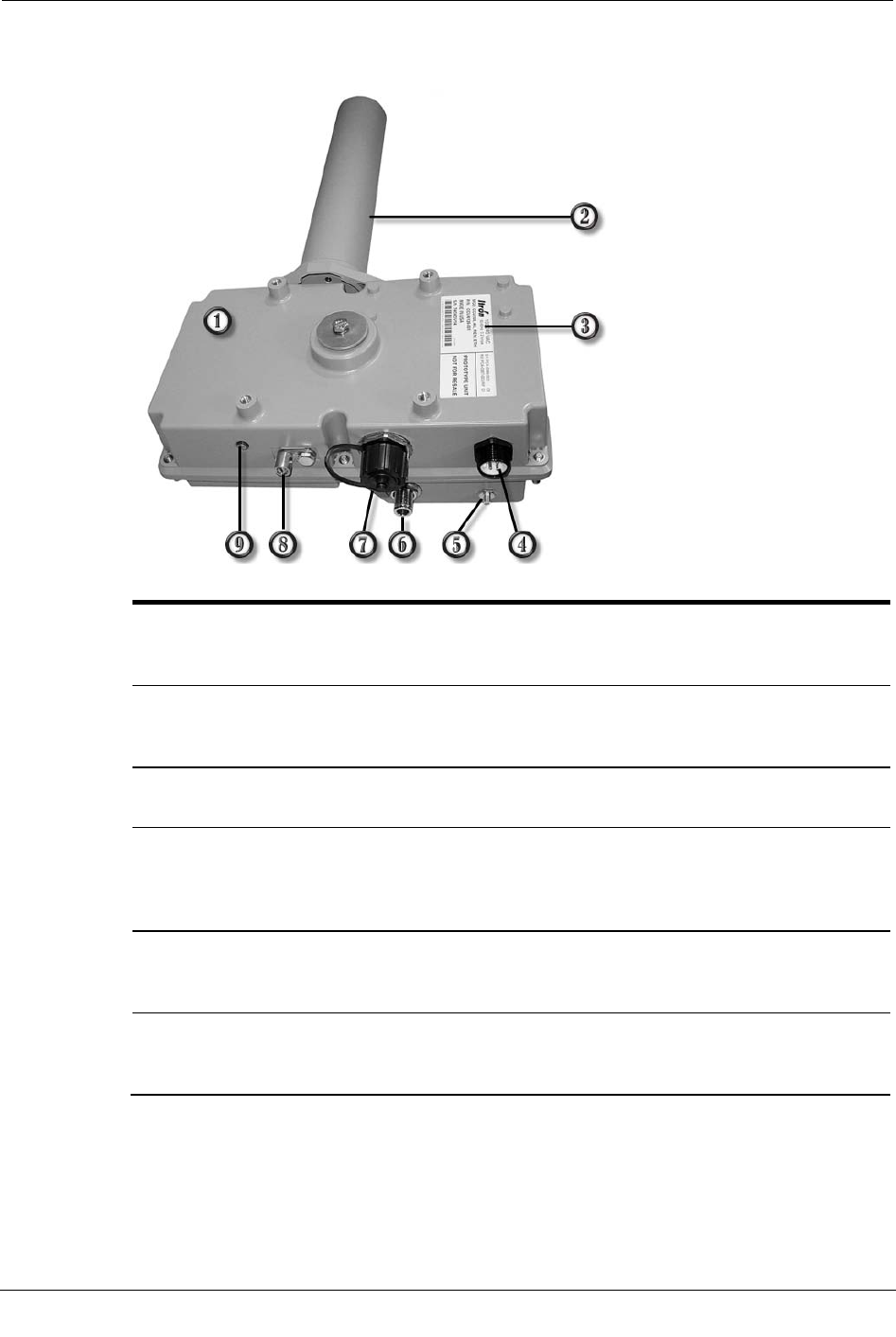
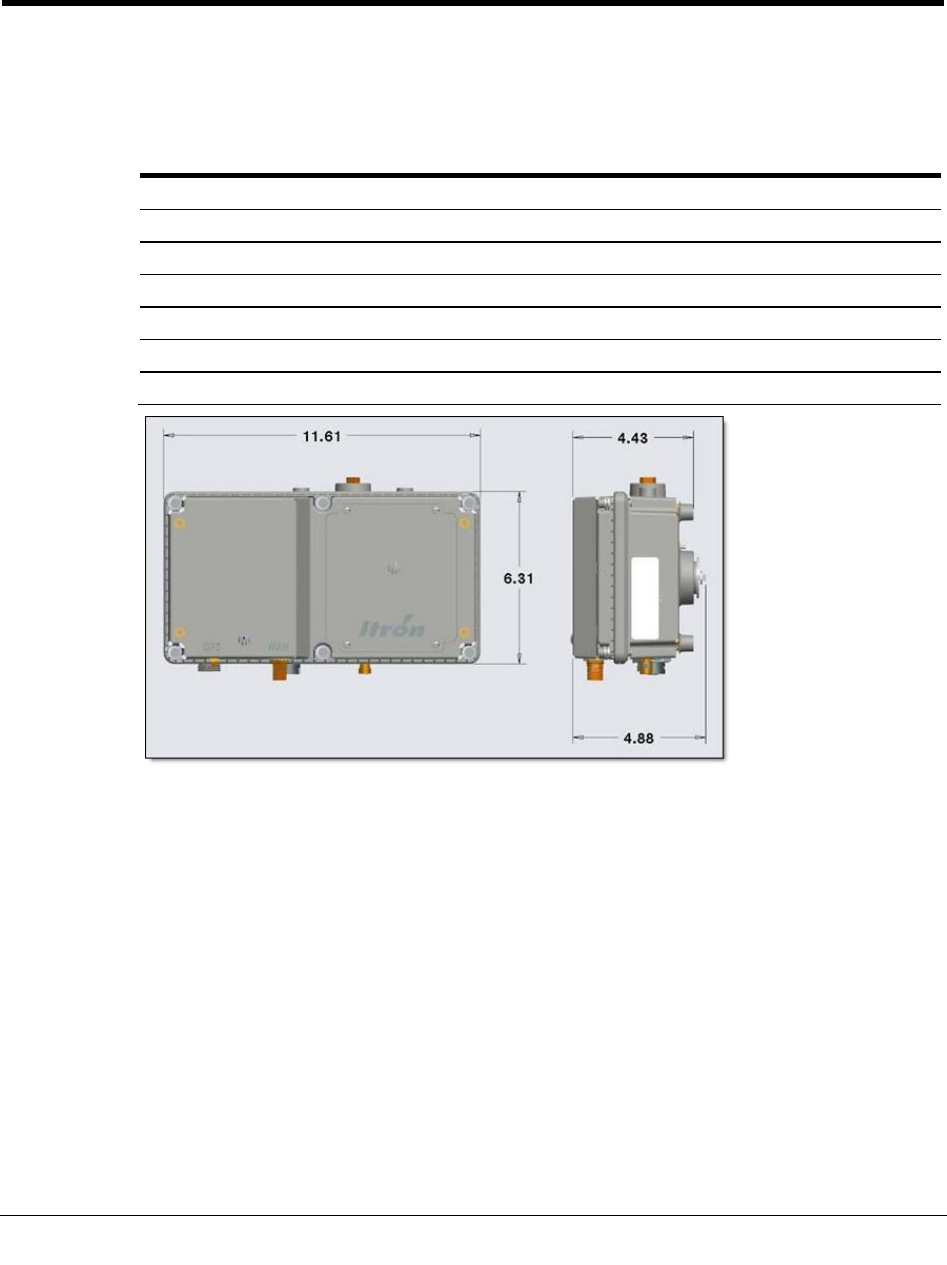
The CCU shown below has connectors for the external GPS/WAN antennas. The
component connections are described in the following table.
Item
Description
1 CCU/Repeater module
Processes data from the antennas and relays it on to the Fixed Network Application Software. Only
authorized Itron personnel may open this module.
2 900 MHz antenna
This 900MHz antenna receives messages from and sends messages to endpoints and repeaters in the
network. The connection for this antenna is a Type N female.
3 CCU/Repeater label
Displays the collector identification number, model number, and other associated information.
4 Power connector
Supplies power to the CCU/Repeater module. AC mains, DC, or solar power options are available. A
three pin cable connects the CCU/Repeater to the mains supply. A two pin cable connects the
CCU/Repeater to a DC supply. A five pin cable connects the CCU/Repeater to the solar system.
5 External GPS antenna connector
This female SMA connector is only on the external antenna CCU/Repeater. Use this connector when
mounting the GPS antenna externally.
6 External WAN antenna connector
This female N connector is only on the external antenna CCU. Use this connector when mounting
the WAN antenna externally.

Chapter 1 CCU/Repeater Basics
4 CCU 100 and Repeater 100 Installation Guide
Proprietary and Confidential
Item
Description
7 Ethernet
Connects the CCU/Repeater to the Ethernet backhaul. Also used to connect the CCU/Repeater to a
router for initial collector setup. Mating weatherproof cables are available from Itron. These cables are
sealed industrial ethernet circular IP67 connectors (CONEC)
Note A waterproof cap seals the Ethernet port from the elements in the field. Be sure to securely
attach the cap once the collector is installed.
8 Ground lug
The ground lug is provided on both the CCU and the Repeater and should be attached to earth ground
if no ground is available in the three conductor power cable or when using a photocell adapter. This
ground helps protect the internal circuitry from high voltage transient events. The ground lug accepts
AWG minimum wire size 14, and maximum wire size 4.
9 Status indicator
This indicator displays the current operational status of the CCU/Repeater. See Status Indicator on
page 61 for more information.
* (Not shown) Battery door
Removal of this door allows access to the replaceable battery pack.
External GPS/WAN Antenna System
The external antenna CCU/Repeater configuration uses a GPS/WAN antenna kit that is
connected to the CCU/Repeater by one or two separate pieces of coaxial cable. Cables are
not included in the kit.
• The WAN antenna is only connected in CCU installations that use a wide area
network backhaul system.
• The GPS antenna is used in all deployments of this system.
The antennas must be installed in a location that allows reception of GPS and WAN
signals.
Itron recommends using a handheld GPS unit to verify that your GPS antenna mounting
location can receive a signal from at least three satellites.
For more information, see GPS and WAN Coverage on page 8.
Caution The external GPS antenna must be oriented vertically when installed, and it
must have an unobstructed view of the sky to properly receive a GPS signal.
CCU/Repeater Components
CCU 100 and Repeater 100 Installation Guide 5
Proprietary and Confidential
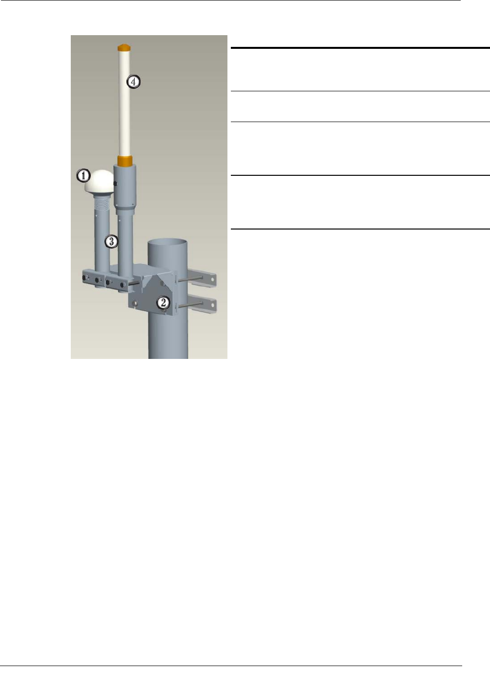
The external GPS/WAN antenna system is shown below.
Item
Description
1 External GPS antenna
Receives GPS data from orbiting satellites. The cable
connection on the bottom of this antenna is TNC Female.
2 Mounting bracket
Attaches the antenna to your desired mounting location.
3 Antenna masts
Provide support for the GPS and WAN antennas. Cables for
each antenna are routed through the masts. Clamps on the front
of the mounting bracket secure the masts.
4 External WAN antenna (CCU only)
Provides the wide-area network (WAN) signal for the CCU.
The Repeater does not use this antenna. The cable connection
on the bottom of this antenna is N Female.
900 MHz Antenna
The 900 MHz antenna transmits and receives data messages from endpoints and repeaters
in the network.
There are three antennas that may be used for the 900 MHz radio link.
• A standard vertically polarized antenna that is directly attached to the CCU/Repeater.
• A standard vertically polarized antenna (5 dBi) that can be connected remotely.
• A high-gain vertically polarized remote antenna (8.15 dBi) that is mounted remotely
in place of the direct attached solution.
Remote antennas must be properly grounded during installation. When a remote antenna
is used, a lightning arrestor is supplied for this purpose.

Chapter 1 CCU/Repeater Basics
6 CCU 100 and Repeater 100 Installation Guide
Proprietary and Confidential
Coaxial cable used to connect the 900 MHz antenna to the CCU/Receiver must be
properly grounded. See Lightning Arrestor on page 12 for more information. All coaxial
cable connections must be properly weather-proofed per industry standards, unless
otherwise specified. If the CCU/Repeater is installed indoors, only the connections
located outside need to be weather-proofed. When the CCU/Repeater is ordered with a
remote 900 MHz antenna kit, some associated mounting hardware is included. Coaxial
cables for the remote 900 MHz antennas are not included in the kit. These cables must be
provided by the installer. Please see Coaxial Cable on page 13 for coaxial cable
specifications.
For more information, see:
• Antenna Specifications on page 56
• Remote 900 MHz Antenna Placement on page 10
• Grounding the Remote/External Antenna Systems on page 11

CCU 100 and Repeater 100 Installation Guide 7
Proprietary and Confidential
This chapter describes how to prepare for a CCU/repeater installation.
Installation Profiles
The CCU/Repeater can be installed in a variety of configurations and locations.
Depending on the installation location, the CCU or Repeater components may be installed
all in the same place (as an integrated solution), or the GPS/WAN antennas may be
installed externally from the CCU/Repeater and the 900 MHz antenna can be installed
remotely (as a distributed solution).
For example, the CCU/Repeater can be installed at the base of a water tower, the external
GPS/WAN antenna system can be mounted further away for optimum reception, and the
900 MHz antenna can be placed at the top of the water tower.
The following profiles have been identified for CCU installation.
Location
Description
Utility pole The CCU/Repeater is installed on a utility pole. The CCU/Repeater should
be mounted as high as possible on the pole for optimum reception.
Light pole The CCU/Repeater is installed on either a light pole or the davit arm that
extends from the light pole. The CCU/Repeater should be mounted as high
as possible on the pole for optimum reception.
Outdoor wall or pipe with remote
900 MHz antenna
The CCU/Repeater is installed on an outside wall or pipe with the 900 MHz
antenna remotely mounted to achieve the maximum elevation and
reception.
Indoor wall or pipe with remote 900
MHz antenna and external
GPS/WAN antennas
The CCU/Repeater is installed inside an equipment room with the 900
MHz antenna remotely mounted to achieve maximum elevation and
reception. The WAN (or other digital cellular) and GPS antenna are
externally mounted to provide acceptable coverage.
Pipe The CCU/Repeater is secured to a pipe or fence railing (from 2 to 3.5
inches in diameter). This type of installation typically occurs on the tops of
water towers.
For more information on these various profiles, as well as the Itron-recommended profile,
see Chapter 3, Installing the CCU/Repeater on page 17.
CHAPTER 2
Planning a CCU/Repeater Installation

Chapter 2 Planning a CCU/Repeater Installation
8 CCU 100 and Repeater 100 Installation Guide
Proprietary and Confidential
Siting CCUs/Repeaters
CCUs/Repeaters are installed in the field on a variety of surfaces, such as wooden or
metal walls, metal pipes, fence railing, and utility poles.
When determining where to place the CCU/Repeater, there are four primary
considerations:
• Siting for optimum RF reception.
• Siting for optimum GPS and/or WAN reception.
• Availability of Ethernet connection (if required).
• Availability of power connection.
• Availability of a structure or location that can physically support the CCU/Repeater
and its mounting hardware.
Caution Always ensure that you have permission to install a CCU/Repeater at
your chosen site prior to beginning installation.
Propagation Study and CCU/Repeater Site Selection
Prior to installing a CCU/Repeater in the field, consult with Itron to perform a
propagation study. This study:
• Evaluates the quantity and types of endpoints in the network.
• Assesses environmental and geographical considerations related to CCU/Repeater
installation.
• Optimizes CCU/Repeater placement in the network for the best possible reception.
• Helps influence the physical and structural implications of mounting a CCU/Repeater
to a given surface.
Once the propagation study is complete, you can determine exactly where to install
CCUs/Repeaters and what they will be mounted to.
GPS and WAN Coverage
CCUs/Repeaters must be installed in locations where a GPS signal is strong and
consistent. If WAN is being used as the communications backhaul for the network, a
strong and consistent WAN signal is required as well (for CCUs only). If the signal is too
weak, or its availability fluctuates, the CCU/Repeater can not gather accurate date/time
information or communicate with the Fixed Network software.
Itron recommends using a handheld GPS unit to verify that your CCU/Repeater or
external GPS antenna mounting location can receive a signal from at least three satellites.

Siting CCUs/Repeaters
CCU 100 and Repeater 100 Installation Guide 9
Proprietary and Confidential
To ensure the best possible signal, avoid installing the CCU/Repeater or the external
antennas in the following ways:
• Adjacent to or between tall buildings, signs, towers, or bridges.
• Near swaying limbs, branches, or cables that could strike and damage the antenna.
• Between, beneath, or near highway overpasses, elevated train platforms, or tunnels.
• Near objects or devices attached to the same pole.
• Within 500 feet of high power radio frequency (RF) transmitters (such as paging
transmitters, cellular transmitters, and municipal communications transmitters).
• Near potential broadband sources of radiated RF energy (such as power line
transformers, RADAR transmitters, cellular antennas, and neon or fluorescent signs).
• Inside metal enclosures (the antennas will not communicate if surrounded by metal)
or inside a building. The CCU/Repeater can be installed in a building or other metal
enclosure, but the antennas must be installed externally.
Warning Before installing a CCU/Repeater near or on the same pole as a
transformer, consult the National Electrical Safety Code (NESC), local utilities,
municipalities, and cable and telephone companies for recommended distances
from transformers and power lines.
AC Service Requirements
A 90 to 265 VAC 10A power source is required at the installation site for the
CCU/Repeater, unless you are using the DC CCU/Repeater or the solar CCU/Repeater.
For more information on these options, see Mains Power Installation Profiles on page 13
or Solar Power Installation Profiles on page 43.
External Ethernet Connections
If the Ethernet is used as the communications backhaul, the CCU installation site must
have Ethernet access. Also, be sure to use weatherproof cables in this type of installation.
Caution When using Ethernet as the communications backhaul, the CCU must be
identified as Ethernet-based when performing Initial Collector Setup (ICS). Failure
to do so prohibits the CCU from communicating with the Network Collection
Engine.

Chapter 2 Planning a CCU/Repeater Installation
10 CCU 100 and Repeater 100 Installation Guide
Proprietary and Confidential
Remote 900 MHz Antenna Placement
Antenna placement is one of the most important factors in determining your overall
system performance. Careful consideration must be given to proper antenna placement.
Follow the general guidelines below when determining the ideal location for a remote-
mounted 900 MHz antenna.
• The antenna must be mounted vertically.
• The antenna needs to be mounted in a location where it has a clear unobstructed 360
degree view of the horizon. The antenna receives and transmits in all directions. Any
objects such as building walls, nearby metal surfaces or other obstructions will
interfere with the proper operation of the antenna. Mounting on a rooftop, where
nearby buildings are higher than the installation location, is not an ideal location for
the antenna.
• Do not mount the antenna near existing RF radiating antennas. If existing RF
radiators are nearby, the horizontal separation distance to the radiator must be a
minimum of 100 feet and/or 10 feet of vertical separation. In instances where nearby
RF radiators are present, conduct an intermodulation interference study to evaluate
the potential for interference and any effects it may have on system performance.
Consult with your Itron systems engineer for more information.
• Height is preferred for optimal performance. Mount the antenna as high as possible,
but Itron recommends that you install the antenna no higher than 100 feet. If the
antenna is going to be more than 100 feet above the CCU, Itron recommends using a
Tower CCU 100.
A side arm antenna installation must be done if the 900 MHz antenna is mounted where it
does not have an unobstructed 360-degree view. Refer to the following guidelines for a
side arm antenna installation.
• For the 900 MHz antenna, the minimum standoff distance is 24 inches, where the
interfering structural members are four inches or less in diameter and spaced more
than eight feet apart.
• For structural members between 4 and 10 inches in diameter, a sliding scale of 2 to 5
feet is to be used. (For example, a 24 inch standoff at 4 inch diameter to a 60 inch
standoff at 10 inch member diameter.)
Provide Itron with any conditions that may impact the CCU/Repeater's performance.

Siting CCUs/Repeaters
CCU 100 and Repeater 100 Installation Guide 11
Proprietary and Confidential
Grounding the Antenna System
To minimize the potential for a lightning event, it is essential that remote/external antenna
systems be properly grounded. Proper grounding prevents the accumulation of static
charges on the antenna system and also provides a direct discharge to ground for any
acquired charges.
All grounding materials and procedures must meet or exceed local codes. Use coaxial
grounding kits recommended by the coaxial cable manufacturer.
Warning Under no circumstances should the antenna grounding wires be run
inside a building. Always install ground bars and grounding material on the
exterior of buildings.
The recommended procedure for grounding an antenna system is as follows:
• Mount a copper ground bar near the antenna. This is the top ground bar.
• Mount a second copper ground bar near the CCU/Repeater. This is the bottom ground
bar.
• Connect the two ground bars with a #6 gauge green jacketed stranded wire or a #2
solid copper wire.
• Ground the antenna mount and the top coaxial ground kit to the top ground bar.
• Ground the bottom coaxial ground kit and the lightning arrestor to the bottom ground
bar.
• Connect the bottom ground bar to one or more earth ground rods.
• All ground wires should be connected straight to ground, with no right angle turns or
sharp bends in the wires.
• Install ground leads on coaxial grounding kits without loops or bends and install
grounding kits in the proper orientation per the manufacturer's specifications.
Chapter 2 Planning a CCU/Repeater Installation
12 CCU 100 and Repeater 100 Installation Guide
Proprietary and Confidential
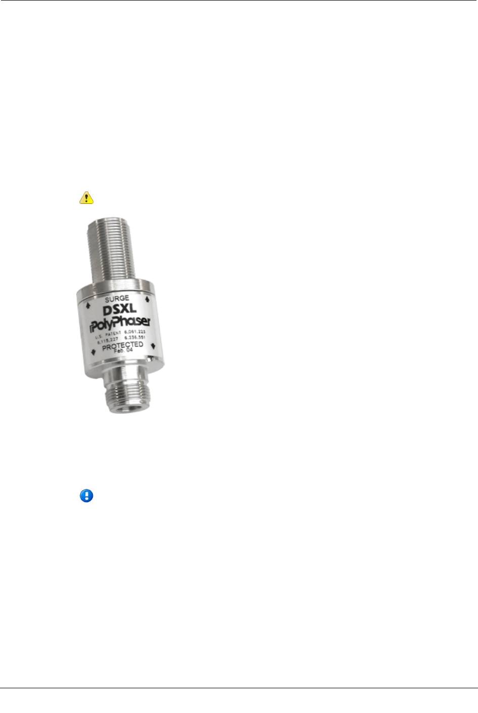
Lightning Arrestor
A lightning arrestor (or surge protector) capable of withstanding multiple lightning strikes
should be installed when using a remote/external antenna. This helps protect the
CCU/Repeater in the event of a lightning strike.
The lightning arrestor is fitted to the coaxial antenna cable at the SURGE end and the RF
jumper cable that connects to the CCU/Repeater module at the PROTECTED end. It
includes a bulkhead connector interface that mounts to a ground plate with a washer and
nut. The arrestor is also furnished with a ground lug, if your installation does not have
provisions for a ground plate. The ground lug on the arrestor is designed for #2AWG
solid or stranded wire. The ground wire must be crimped to this lug, never soldered.
Caution The lightning arrestor must be connected to an earth-ground.
The top and bottom ends of the coaxial cable attached to the tower should be electrically
grounded with kits for lightning protection. The antenna input connection cannot serve as
the top ground point. For cable lengths in excess of 200 feet, ground the vertical cable run
every 100 feet.
Note The installer must supply any mounting brackets and cable-management clips
to secure the coaxial cable to the tower or structure, when using a remote/external
antenna. Consult your cable manufacturer for specifications on proper clips and
grounding kits. Conduit clamps and tie wraps are not satisfactory methods for
securing coaxial cables.
For a remote 900 MHz installation with a high gain antenna, a lightning arrestor is
supplied by Itron in the CCU 100/Repeater 100 kit materials.

AC Mains Power
CCU 100 and Repeater 100 Installation Guide 13
Proprietary and Confidential
AC Mains Power
The AC mains wiring to the CCU/Repeater utilizes a three conductor cable. This cable
can be terminated with either a NEMA L5-15 (125V, 15A) or a NEMA L6-15 (250V,
15A) locking plug in order to meet local electrical codes. The CCU should be powered by
a dedicated 10A circuit. The CCU/Repeater should not be connected to a circuit protected
by a GFCI breaker. Power wiring on the Itron supplied power cable follows conventional
color coding for AC wiring: Green/Ground, White/Neutral, Black/Hot.
Warning The CCU/Repeater must be grounded by using either the ground wire
in the three conductor cable or the grounding lug on the bottom of the
CCU/Repeater. For installations that use the photocell adapter the grounding
lug must be used to ground the CCU.
DC Mains Power
The DC wiring to the CCU/Repeater utilizes a two conductor cable. The CCU should be
connected to a 10A DC circuit breaker or fuse. Wiring of the Itron supplied two conductor
cable is accomplished by attaching the red wire to a +12V source and attaching the black
wire to ground.
Materials Not Provided by Itron
The following materials are not provided by Itron in the CCU/Repeater kit, but are
required for installation.
Please acquire these items prior to beginning an installation.
• Coaxial cable on page 13 (for remote/external antennas)
• Connectors on page 15
• Mounting hardware on page 15
Coaxial Cable
When mounting the remote/external antennas, coaxial cable must be supplied to connect
the antenna to the CCU/Repeater. The proper size of cable is dependent on total cable
length and frequency. Coaxial cable also requires proper hoisting grips, ground kits,
connectors, jumpers, hangers, and weather proofing material. Coaxial cable and
accessories are not provided by Itron. Coaxial cable systems must be installed according
to the manufacturer's specifications. Itron recommends using qualified radio installation
contractors to install the remote/external antenna system.
Remote Mount 900 MHz Antenna on a Standard CCU/Repeater
When selecting cable for the remote mount 900 MHz antenna on the standard (non-tower)
CCU/Repeater, total cable loss cannot exceed 1.5 dB to maintain system performance.
Allow 0.1 dB loss for each connector.

Chapter 2 Planning a CCU/Repeater Installation
14 CCU 100 and Repeater 100 Installation Guide
Proprietary and Confidential
Remote Mount High Gain (8.15 dBi) 900 MHz Antenna on a Tower
CCU
The table below lists several options for coaxial cable that can be used with the remote
mount high gain 900 MHz antenna. when installing the high gain antenna on a Tower
CCU the FCC has set limits to the maximum transmit power of the CCU. In order to meet
these limits, Tower CCUs with FCC ID number EO9CCU100T must have a minimum of
2.2 dB worth of loss (but not more than 3.5 dB) between the tower cabinet and the
antenna. All other tower CCUs should be installed with minimum cable loss.
Allow 0.1 dB loss for each connector. If required, a 1 dB attenuator (similar to the
Pasternack PE7002-1) may be used to attain the desired power at the antenna.
Total Coaxial length
Coax specification 0-120 ft. 121-200 ft. (high-
gain antenna
only)
201-250 ft. (high-
gain antenna
only)
Standard black jacket cable AVA5-50 AVA6-50 AVA7-50
Optional fire retardant cable AVA5RK-50 AVA6RK-50 AVA7RK-50
Cable diameter (nominal) 7/8 in. 1-1/4 in. 1-5/8 in.
Cable weight (lb./ft.) 0.33 0.46 0.70
Minimum bend radius 10 in. 8 in. 15 in.
Cable attenuation @ 915 MHz ~ 1.2 dB/100 ft. ~ 0.84 dB/100 ft. ~0.70 dB/100 ft.
External GPS and WAN Antennas
The primary requirement for any coaxial cable used with the external GPS or WAN
antenna is to have less than 5 dB of attenuation at 1.5 to 1.8 GHz for the entire length of
cable, including connector losses.
You may use any type of 50 ohm coaxial cable, as long as the total loss, including
connectors is less than 5 dB at 1.5 to 1.8 GHz.
If you are using coaxial cable larger (or stiffer) than 1/2 inch superflex, add a short (less
than 5 feet) piece of LMR 400 cable to each end before connecting the cable to the CCU
and the antennas. Use the appropriate connectors between the LMR 400 and larger
coaxial cable.
If the antennas are mounted in an exposed outdoor environment, you must provide
lightning protection and proper grounding. For more information on lightning protection
and grounding, see Lightning Arrestor on page 12, Grounding the Remote/External
Antenna Systems on page 11 and the Motorola R-56 guidelines.
Materials Not Provided by Itron
CCU 100 and Repeater 100 Installation Guide 15
Proprietary and Confidential
Antenna Sweep Test
After remote antenna installation perform an antenna system sweep test and verify that
VSWR (voltage standing wave ratio) does not exceed 1.5:1. For more information, see
Perform an Antenna Sweep Test on page 62.
Caution All coaxial cable used to connect an antenna to the CCU/Repeater must be
properly grounded at the top and bottom of the coaxial line. Additionally, any cable
lengths of 200 feet or greater must be grounded each 100 feet. See Lightning
Arrestor on page 12 for more information.
Antenna Connectors
Connectors for the 900 MHz and WAN antenna cables need to be male Type N
connectors and must be sized according to the type of coaxial cable used. The GPS cable
requires TNC male and SMA male connectors. These connectors are available from a
variety of manufacturers.
Important All coaxial cable connections must be properly weather-proofed per
industry standards unless otherwise specified. If the CCU/Repeater is installed
indoors, only the connections located outside need to be weather-proofed.
Mounting Hardware
Depending on your installation location and configuration, the following mounting
hardware must be supplied by the installer to properly attach the CCU/Repeater to the
mounting surface.
Caution Since each installation is unique, you must ensure that the mounting
hardware you supply can securely support the CCU/Repeater. The CCU/Repeater
(minus attachment hardware) weighs 7 pounds. Itron recommends consulting with a
qualified engineer to verify load requirements and safety issues. Also, be sure to
check and comply with local codes when installing the CCU/Repeater.
Profile
Mounting surface
Suggested hardware/sizing
Utility pole Wood or steel pole High-strength stainless steel straps
Light pole Steel light pole High-strength stainless steel straps
Outdoor wall or pole
with remote 900 MHz
antenna
Concrete, wood, or steel wall 1/4 inch-20 lag screws or 1/4 inch-20 molly bolts
Wood or steel pole High-strength stainless steel straps
Indoor wall or pole
with remote 900 MHz
antenna and external
GPS/WAN antennas
Concrete, wood, sheetrock, or
steel wall
1/4 inch-20 lag screws or 1/4 inch-20 molly bolts
Wood or steel pole High-strength stainless steel straps
Pipe 2.5 inch to 3.5 inch
galvanized steel pipe
Two pipe mount brackets for pipes up to 3.5 inches in
diameter, supplied by Itron (part number FAB-0192-001,
two brackets are required for each CCU/Repeater).

Chapter 2 Planning a CCU/Repeater Installation
16 CCU 100 and Repeater 100 Installation Guide
Proprietary and Confidential
CCU 100 and Repeater 100 Installation Guide 17
Proprietary and Confidential
This chapter shows you how to install a CCU/Repeater in the field, using the Itron-
recommended installation method.
The CCU/Repeater can be installed in a variety of ways. Several different CCU/Repeater
installation profiles are shown in this chapter, for both mains powered and solar powered
CCU/Repeaters.
Warning Before installing a CCU/Repeater, ensure that the selected location can
support the weight of the CCU/Repeater and mounting hardware. A thorough
structural analysis should be performed by a qualified engineer at your desired
location prior to installation. Itron is not responsible for improper installations or for
installations at a site that cannot adequately support the CCU/Repeater.
Installation Overview
The following section shows you how to install a CCU/Repeater using the Itron-
recommended profile. This profile calls for the CCU/Repeater to be mounted to a 2 inch
diameter vertical pipe. A 110V source supplies mains power to the CCU/Repeater.
Caution Prior to installing a CCU in the field, be sure to configure it as described in
the Collector Configuration Application v4.0 User Guide. A CCU cannot be
configured after it has been installed in the field. Repeaters do not require pre-
installation configuration.
There are several main steps to perform. Each step is described in more detail in the
following sections.
1. Attach the external GPS/WAN antennas (on page 18) (if necessary).
2. Attach the direct mount 900 MHz antenna (on page 19) (if necessary).
3. Attach the CCU/Repeater to the mounting surface on page 21.
4. Connect the cables on page 29.
5. Install the battery on page 32.
Caution Do not move or transport the CCU without first disconnecting power.
Moving or tilting a CCU with power connected may cause the CCU to reset to the
factory image.
6. Provide power on page 35.
7. Perform an antenna sweep test on page 62.
CHAPTER 3
Installing the CCU/Repeater
Chapter 3 Installing the CCU/Repeater
18 CCU 100 and Repeater 100 Installation Guide
Proprietary and Confidential
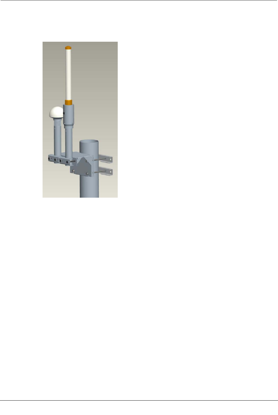
Attaching the External GPS/WAN Antennas
The external GPS and WAN antennas can be attached to pipes, poles, walls, and davit
arms. A typical pole mount assembly is shown below.
To attach the external GPS/WAN antennas
1. Assemble the antenna unit as described in the GPS/WAN Remote Antenna Mounting
Kit Assembly Guide included with the GPS/WAN External Antenna Mounting Kit.
2. Attach the GPS/WAN antenna unit coaxial cable as described in "To connect cables"
on page 29.
Attaching the Direct Mount 900 MHz Antenna
CCU 100 and Repeater 100 Installation Guide 19
Proprietary and Confidential
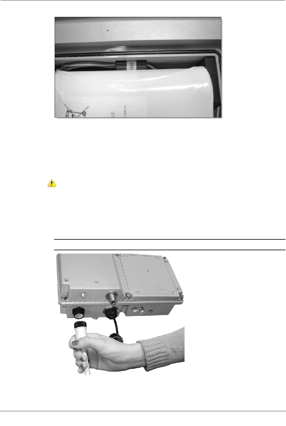
Attaching the Direct Mount 900 MHz Antenna
Attach the direct mount 900 MHz antenna before mounting the CCU/Repeater in its
permanent location.
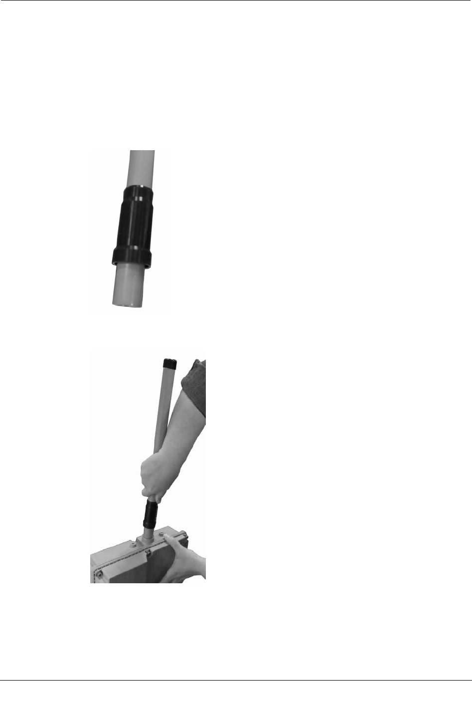
To attach the direct mount 900 MHz antenna
1. Slide the black rubber boot onto the base of the antenna as shown in the following
illustration.
2. Screw the antenna onto the top of the CCU/Repeater. Be careful not to cross-thread
the connectors. Do not over-tighten.
Chapter 3 Installing the CCU/Repeater
20 CCU 100 and Repeater 100 Installation Guide
Proprietary and Confidential
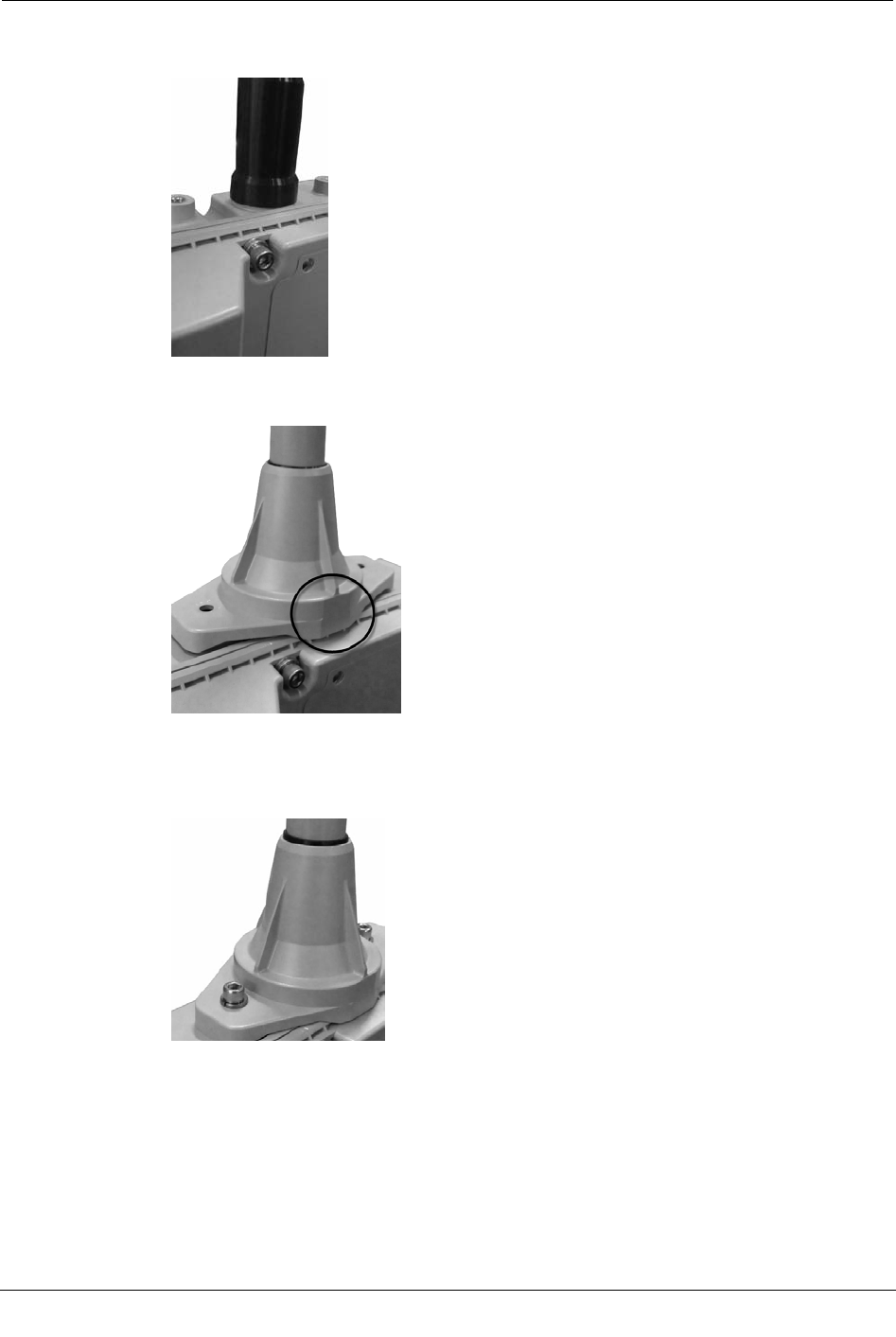
3. Push the rubber boot as close as possible to the top of the CCU as shown in the
following illustration.
4. Slide the antenna sleeve over the antenna, ensuring that the front of the antenna sleeve
is to the front of the CCU/Repeater.
5. Using the included screws and washers, screw the antenna sleeve to the top of the
CCU/Repeater. Tighten the screws to 5 to 6 in/lbs.
Antenna sleeve > flat washer > lock washer > screw
Attaching the CCU/Repeater
CCU 100 and Repeater 100 Installation Guide 21
Proprietary and Confidential
Attaching the CCU/Repeater
The CCU/Repeater may be attached to a variety of surfaces. See the following sections
for diagrams showing some of the possible configurations.
• Pipe mount on page 22
• Pole mount on page 24
• Wall mount on page 26
• Davit arm mount on page 27
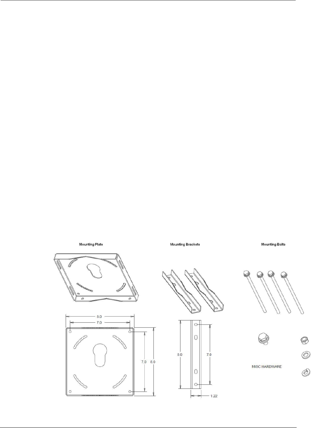
Mounting Hardware
This set of hardware can be adapted to mount the CCU/Repeater in many different
locations.
For pole or pipe mounts, the mounting hardware consists of a mounting plate, two
brackets, four bolts, and a set screw.
For a wall mount, use two metal brackets (not shown below), four mounting bolts, nuts,
and lock washers to prepare the CCU for mounting. Itron does not supply the hardware
necessary to mount the CCU wall mounting brackets to the wall.
An integrated mounting support on the back of the CCU/Repeater enclosure slides into
the slot in the center of the mounting bracket. A set screw locks the CCU/Repeater to the
mounting bracket. Orientation of the enclosure may be adjusted +/- 16 degrees horizontal
to compensate for different angles.
Chapter 3 Installing the CCU/Repeater
22 CCU 100 and Repeater 100 Installation Guide
Proprietary and Confidential
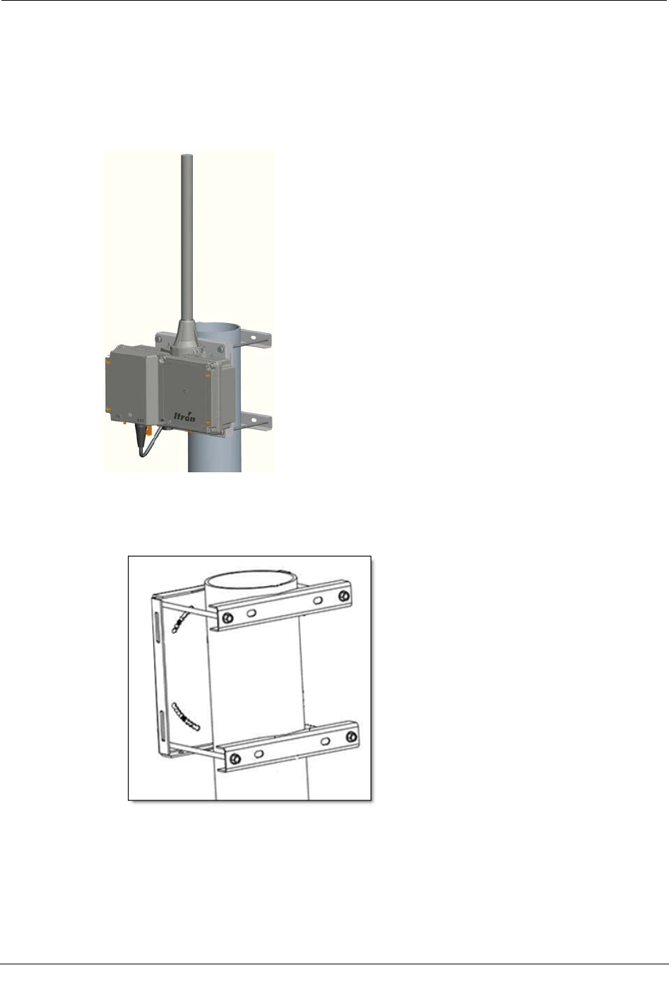
Pipe Mount
The image below illustrates a typical vertical pipe installation. The CCU/Repeater may
also be attached to a horizontal pipe.
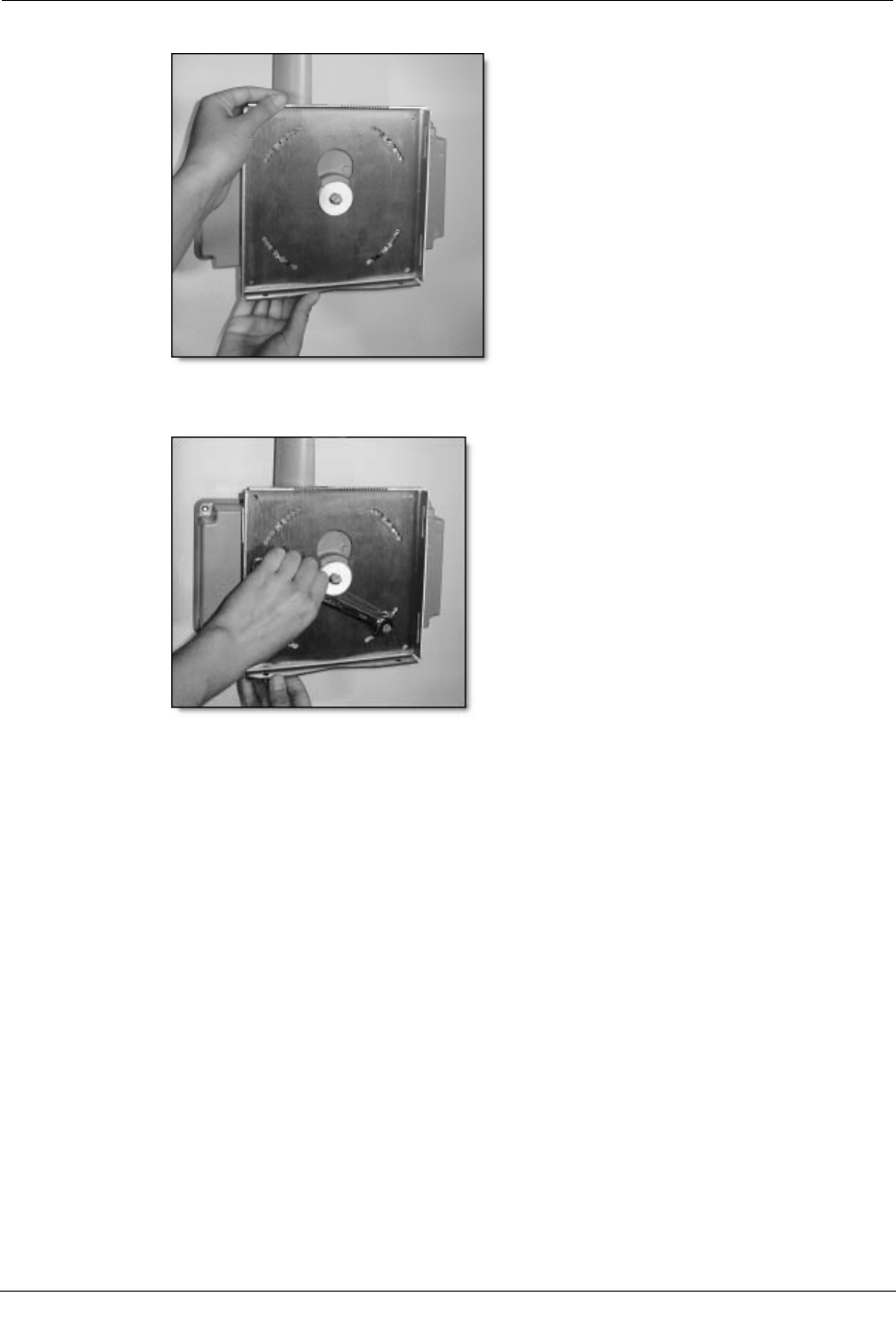
In this case the CCU/Repeater mounting plate is attached to the vertical pipe with the
mounting brackets and the CCU/Repeater enclosure is secured to the mounting plate.
To mount the CCU/Repeater on a pipe
1. Using the two mounting brackets and four bolts, attach the mounting plate to the pipe.
2. Attach the mounting disc to the back of the CCU with the included parts in the
following order.
CCU > mounting disk > flat washer > lock washer > bolt
Attaching the CCU/Repeater
CCU 100 and Repeater 100 Installation Guide 23
Proprietary and Confidential
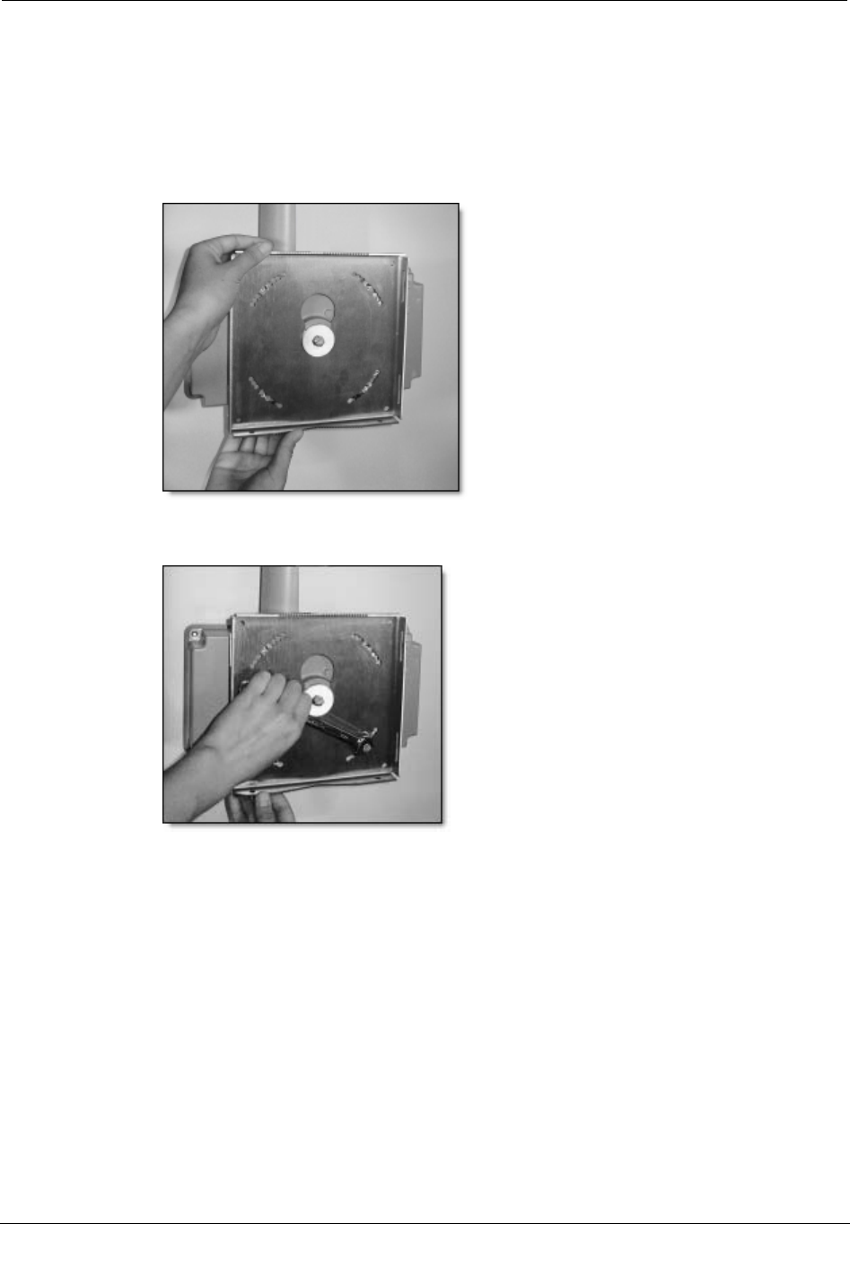
3. Insert the mounting disc into the mounting plate keyhole.
4. Using the provided set screws, secure the CCU to the mounting plate with the antenna
in the upright position.
Chapter 3 Installing the CCU/Repeater
24 CCU 100 and Repeater 100 Installation Guide
Proprietary and Confidential
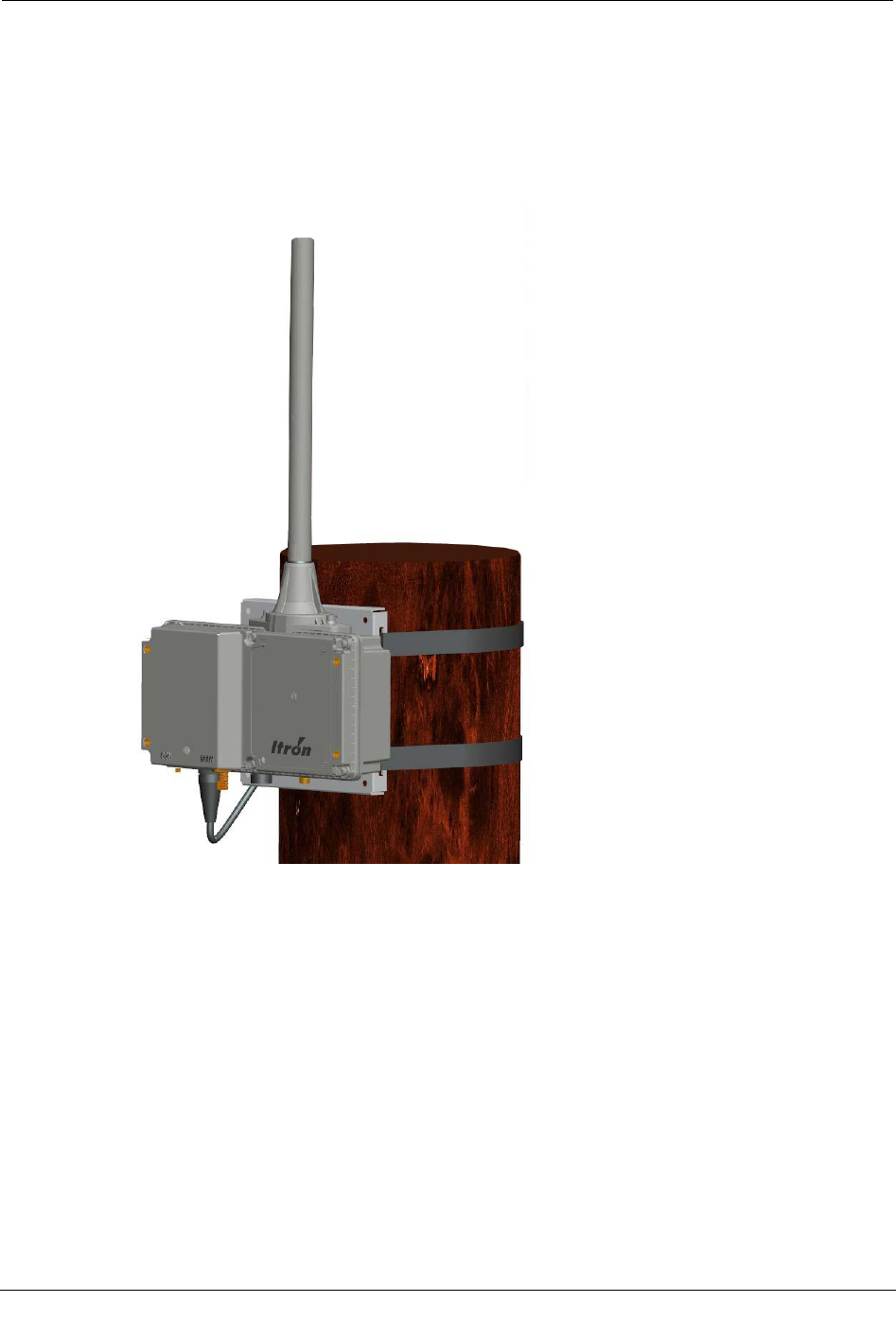
Pole Mount
If the vertical pipe or pole exceeds 6.75 inches in diameter, metal bands may be used in
place of the mounting brackets to secure the mounting plate to the pipe or pole. Two sets
of slots (1.5 in. long) on the mounting plate are provided for the metal bands. It may be
necessary to use the remote 900 MHz antenna kit to achieve optimum RF performance
and GPS coverage if the pole obstructs the desired RF path.
Attaching the CCU/Repeater
CCU 100 and Repeater 100 Installation Guide 25
Proprietary and Confidential
To mount the CCU/Repeater on a pole
1. Attach the mounting disc to the back of the CCU with the included parts in the
following order.
CCU > mounting disk > flat washer > lock washer > bolt
2. Insert the mounting disc (on the back of the CCU) into the mounting plate keyhole.
3. Using the provided set screws, secure the CCU to the mounting plate with the antenna
in the upright position.
4. Using two steel straps, attach the mounting plate to the pole.
Chapter 3 Installing the CCU/Repeater
26 CCU 100 and Repeater 100 Installation Guide
Proprietary and Confidential
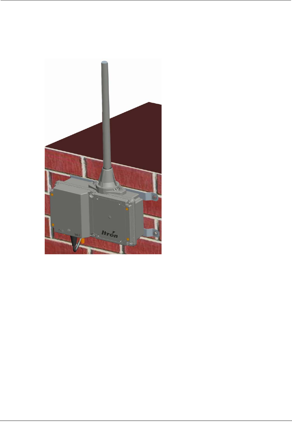
Wall Mount
The following image illustrates a wall mount installation. In this scenario two brackets
are secured to the flat wall surface and the CCU/Repeater is bolted to the brackets. It may
be necessary to use the remote 900 MHz antenna kit to achieve optimum RF performance
and GPS coverage if mounted indoors or if the wall obstructs the desired RF path.
To mount the CCU/Repeater on a wall
1. Using four bolts, secure the CCU to the two wall mounting brackets with the antenna
in the upright position.
2. Using four appropriate screws or bolts (not provided by Itron), attach the mounting
brackets to the wall.
Attaching the CCU/Repeater
CCU 100 and Repeater 100 Installation Guide 27
Proprietary and Confidential
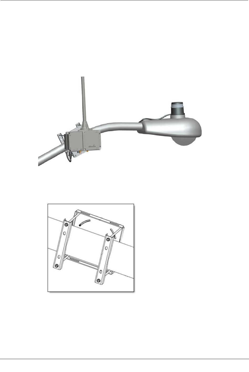
Davit Arm Mount
The figure below illustrates a typical utility pole or street light pole installation. The
CCU/Repeater is mounted on a davit arm or the street light arm. Two types of power
connections are typical. A photocell adapter cable may be used when the CCU/Repeater is
mounted on a street light arm. This cable plugs into the photocell sensor of the street light.
Use of the photocell adapter requires that the CCU/Repeater be grounded using the
grounding lug on the bottom of the CCU/Repeater. If the CCU/Repeater is mounted on a
davit arm with no street light, the power cable must be connected according to local
electrical codes.
To mount the CCU/Repeater on a davit arm
1. Using the two mounting brackets and four bolts, attach the mounting plate to the davit
arm.
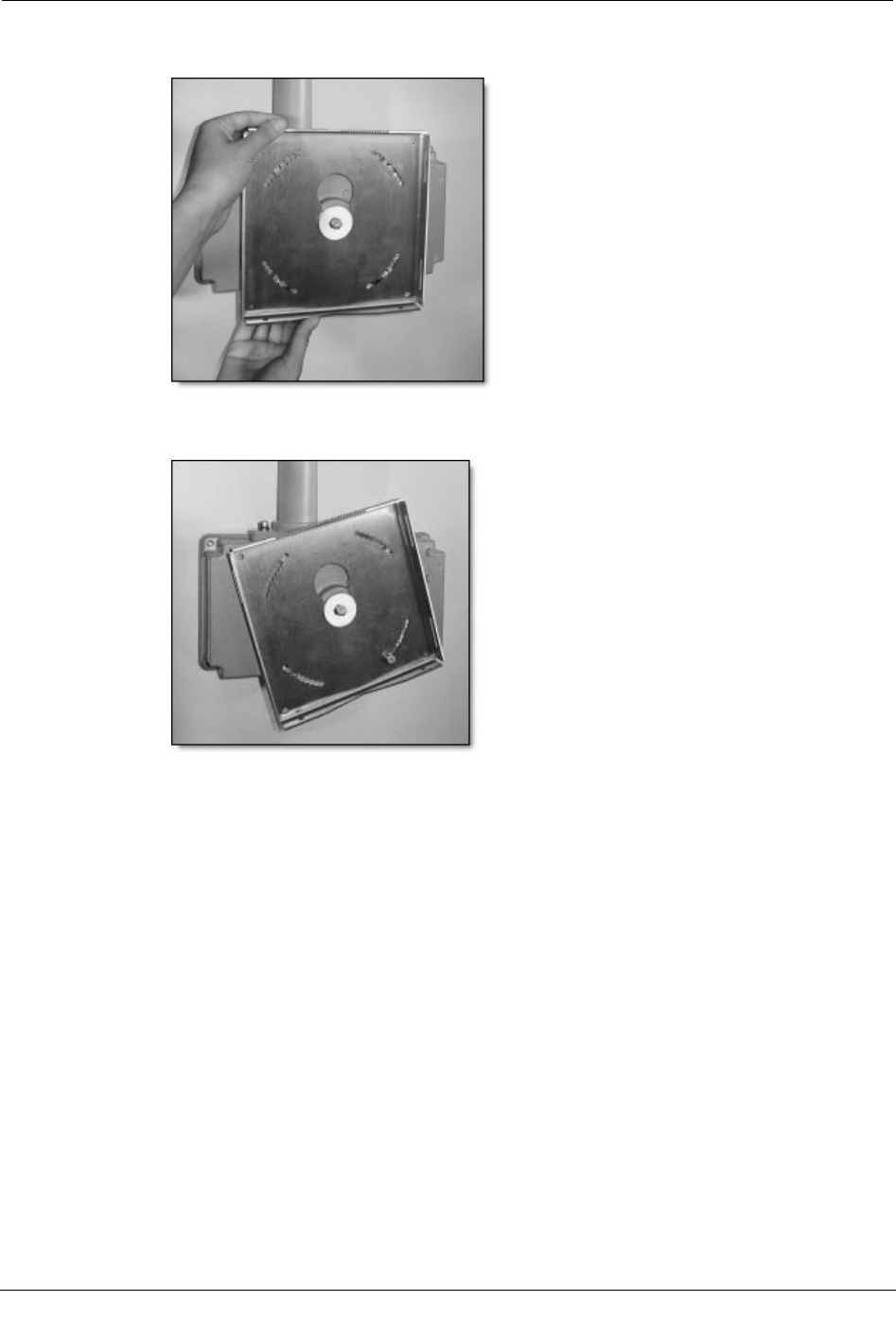
2. Attach the mounting disc to the back of the CCU with the included parts in the
following order.
CCU > mounting disk > flat washer > lock washer > bolt
Chapter 3 Installing the CCU/Repeater
28 CCU 100 and Repeater 100 Installation Guide
Proprietary and Confidential
3. Insert the mounting disc into the mounting plate keyhole. The following photos are
shown off the davit arm for clarity.
4. Using the provided set screws, secure the CCU to the mounting plate with the antenna
in the upright position.

Connecting Cables
CCU 100 and Repeater 100 Installation Guide 29
Proprietary and Confidential
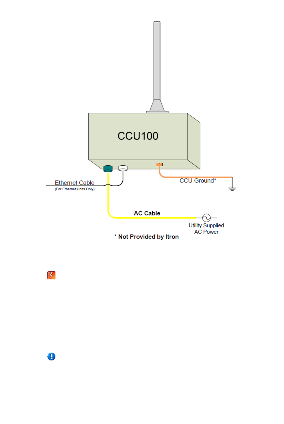
Connecting Cables
Connect the remote/external antenna cables (if needed), Ethernet cable (if needed), and
grounding wire.
Because of the variable requirements for cable length, cables are not provided by Itron.
Important All coaxial cable connections must be properly weather-proofed per
industry standards unless otherwise specified. If the CCU/Repeater is installed
indoors, only the connections located outside need to be weather-proofed.
To connect cables
1. The GPS cable has an SMA connector on one end and a TNC connector on the other
end. Connect the SMA connector end of the GPS antenna cable to the CCU/Repeater.
Connect the TNC end of the GPS cable to the external GPS antenna.
2. The WAN cable has an N connector on each end. Connect one end of the WAN
antenna cable to the CCU. Connect the other end of the cable to the external WAN
antenna.
Note Repeaters do not use WAN antennas.
Chapter 3 Installing the CCU/Repeater
30 CCU 100 and Repeater 100 Installation Guide
Proprietary and Confidential
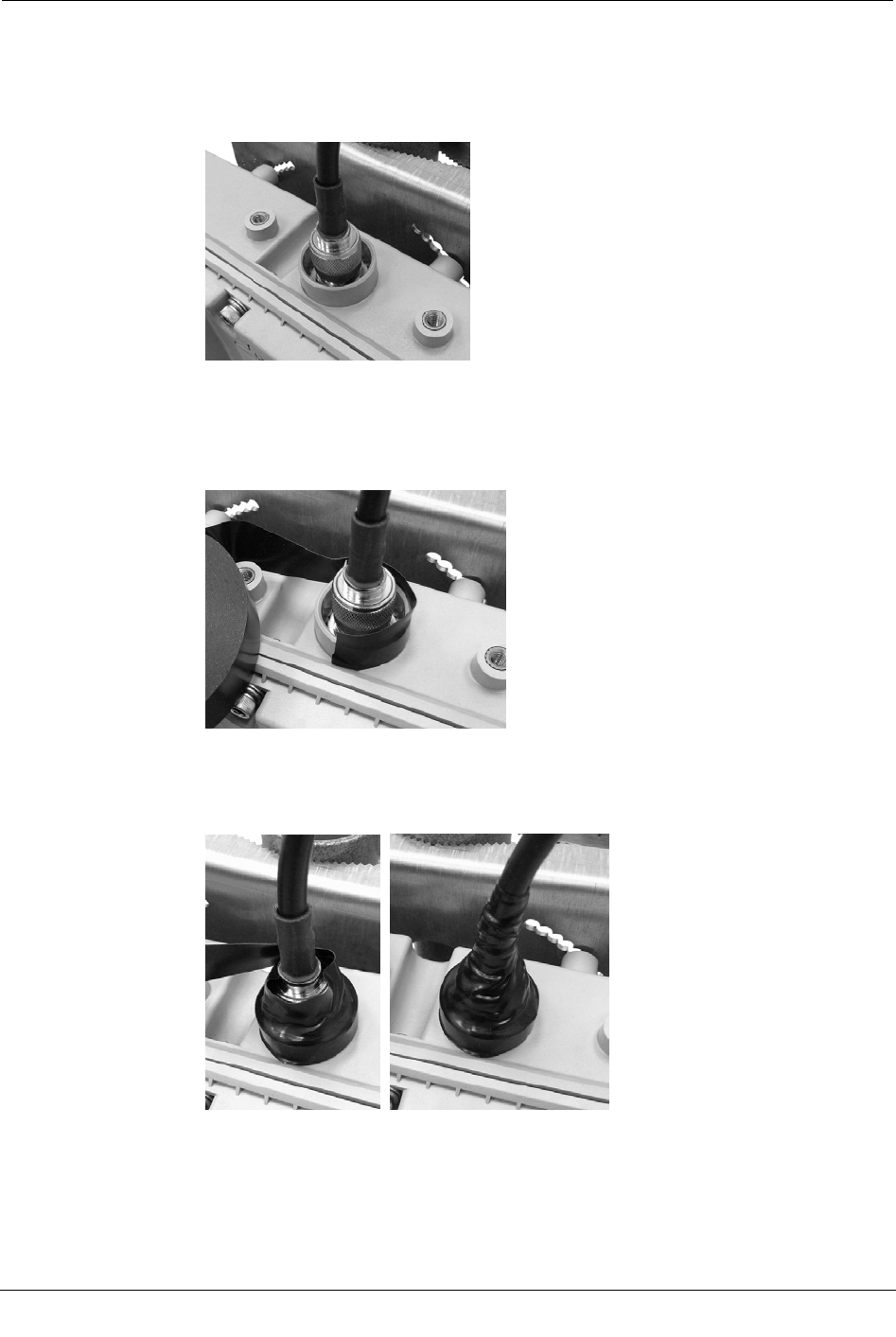
3. If you are using a remote 900 MHz antenna, attach the 900 MHz antenna cable to the
connector on the top of the CCU/Repeater. This connection must be weatherproofed
as described in the following steps.
a. Attach the coaxial cable to the top of the CCU.
b. Wrap vinyl electrical tape around the connection starting at the CCU and
wrapping up the cable as shown in the following illustration.
The vinyl electric tape provides a foundation for the butyl rubber sealant making
it easier to disconnect the cable.
c. Wrap the vinyl electric tape up the coaxial cable overlapping each wrap as shown
in the following illustrations.
Ensure the tape fully covers the cable strain relief.
Connecting Cables
CCU 100 and Repeater 100 Installation Guide 31
Proprietary and Confidential
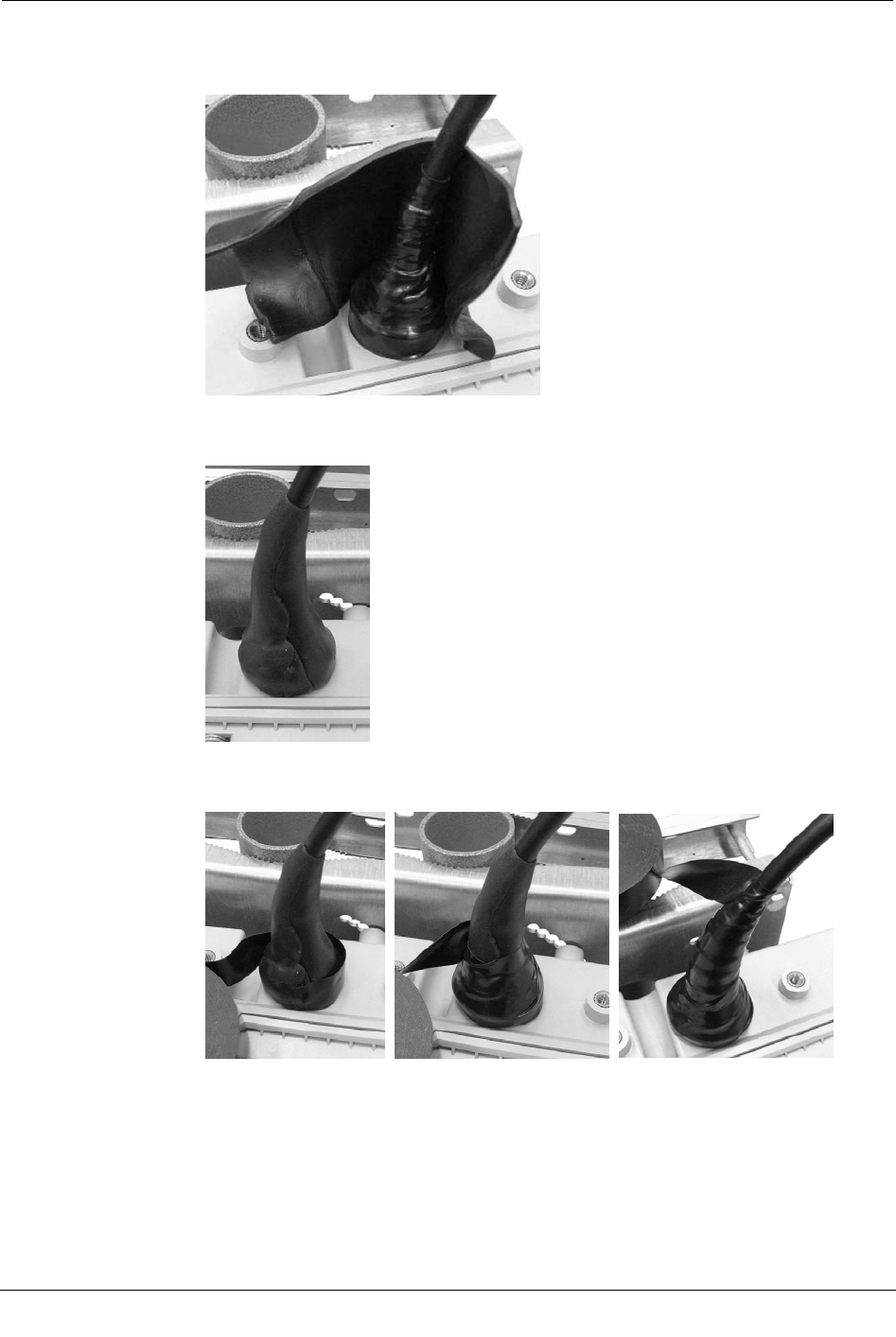
d. Wrap a layer of butyl rubber sealant over the vinyl electric tape.
Ensure that the butyl rubber extends past the vinyl tape and onto the cable jacket.
e. Overlap the butyl rubber so there is no gap. The butyl rubber will self-vulcanize
over time and the seam will disappear.
f. Wrap vinyl electric tape around the butyl rubber starting at the CCU and
wrapping up as you did in step a.
Chapter 3 Installing the CCU/Repeater
32 CCU 100 and Repeater 100 Installation Guide
Proprietary and Confidential
g. Continue wrapping the vinyl tape in a spiral back down to the CCU. You now
have two layers of vinyl tape covering the butyl rubber.
4. If you are using an Ethernet backhaul, attach the Ethernet cable ensuring the weather-
tight connector is properly secured. If the Ethernet connection is not used, secure the
weatherproof cap.
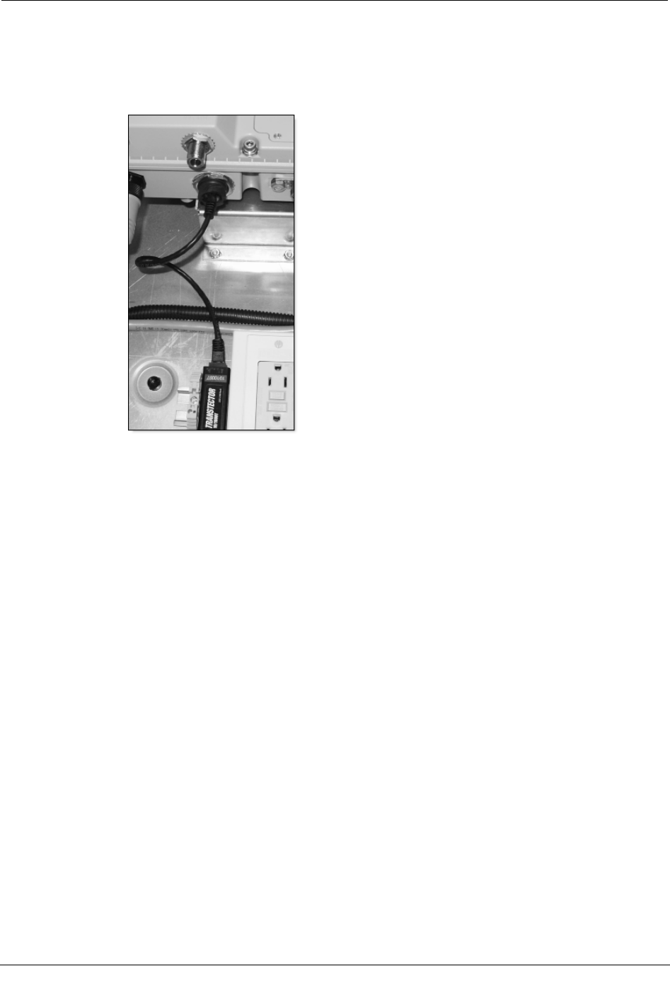
5. The grounding lug should be attached to earth ground according to local codes.
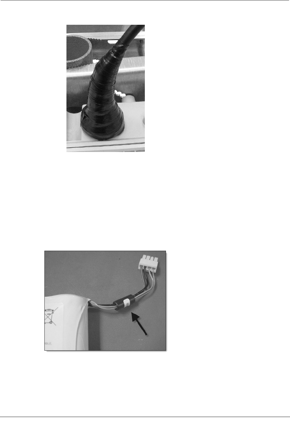
Installing the Battery
If you are installing a newer battery that has a ferrite bead on the cables, as shown in the
following illustration, follow the directions in "To install a battery (ferrite bead)" on page
34.
Otherwise, see "To install a battery" on page 33.
Installing the Battery
CCU 100 and Repeater 100 Installation Guide 33
Proprietary and Confidential
To install the battery
1. Remove the battery cover by loosening the four screws securing it.
These are captive screws and do not need to be fully removed from the battery cover.
2. Plug in the four pin battery wiring harness. The harness should snap into place,
providing a secure connection.
3. Slide the battery into the battery compartment.
4. Replace the battery compartment cover, and torque the screws to 6 inch-pounds.
Chapter 3 Installing the CCU/Repeater
34 CCU 100 and Repeater 100 Installation Guide
Proprietary and Confidential
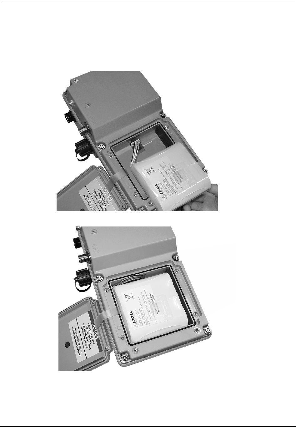
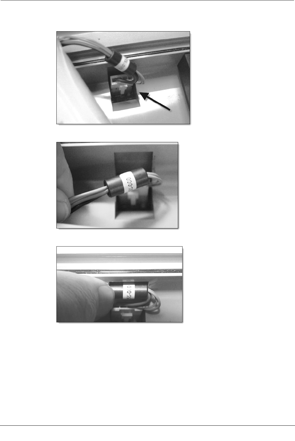
To install a battery (ferrite bead)
1. Insert the battery connector into the connector on the CCU 100.
2. Align the edges of the ferrite bead with the edges of the recess in the battery well.
3. Press the ferrite bead into the recess in the battery well.
Providing Power
CCU 100 and Repeater 100 Installation Guide 35
Proprietary and Confidential
4. Place the battery in the battery well as shown in the following illustration.
Providing Power
The final step of the CCU/Repeater installation is to provide power to the CCU.
Depending on the CCU/Repeater model, either a two pin cable (DC), three pin cable
(AC), or a five pin cable (solar) is required.
Caution Do not move or tilt the CCU for one minute after connecting power.
Moving or tilting a CCU too soon after connecting power may cause the current
configuration to be lost.
To provide power
1. Plug the appropriate cable in to the CCU/Repeater.
Note The connector is keyed so that the cable can connect in only one orientation.
2. Securely fasten the power cable to the CCU/Repeater by tightening the retaining nut
on the cable.
Chapter 3 Installing the CCU/Repeater
36 CCU 100 and Repeater 100 Installation Guide
Proprietary and Confidential
AC Installation Diagram
Tower Installation
Warning Before installing a Tower CCU, ensure that the selected location can
support the weight of the Tower CCU and mounting hardware. A thorough
structural analysis should be performed by a qualified engineer at your desired
location prior to installation. Itron is not responsible for improper installations or
for installations at a site that cannot adequately support the Tower CCU.
All coaxial cable connections must be properly weather-proofed per industry standards
unless otherwise specified. This includes any connections for the antennas and the Tower
CCU. If the Tower CCU is installed indoors, only the connections located outside need to
be weather-proofed.
Important To prevent exceeding the maximum EIRP set by the FCC, there must
be at least 2 dB of loss between the antenna connector at the base of the tower
cabinet and the high gain 900 MHz antenna. Do not exceed 3.5 dB of loss to
maintain system performance. Only use the Itron approved high gain antenna.
Tower Installation
CCU 100 and Repeater 100 Installation Guide 37
Proprietary and Confidential
Because of the size and weight of the Tower CCU, Itron recommends that more than one
person be present for the installation. See Antenna Specifications on page 53 for more
information.
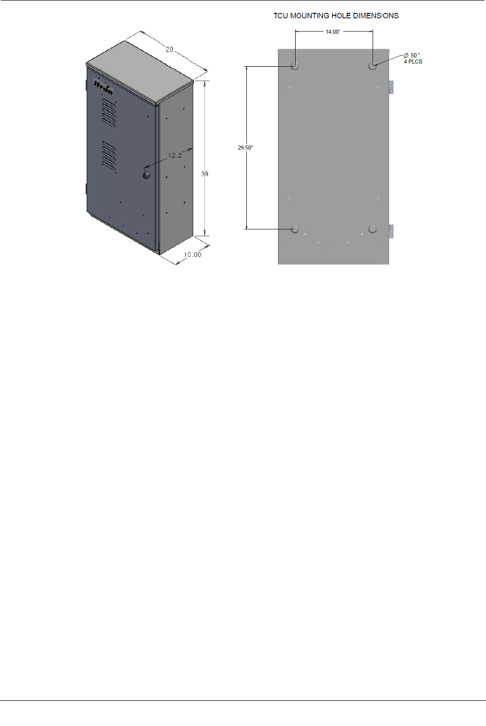
Tower Installation Overview
The Tower CCU 100 (TCU) installation differs significantly from other CCU 100
installation profiles in that the CCU 100 is installed within a cabinet enclosure at the base
of a radio tower and all of the antennas are mounted externally and remotely. The
standard cabinet protects the hardware from adverse environmental conditions and
provides easy access for servicing the CCU and its related components.
The TCU box comes preassembled except for the CCU. The CCU must have the ICS
procedure performed prior to installing the CCU in the TCU box.
Chapter 3 Installing the CCU/Repeater
38 CCU 100 and Repeater 100 Installation Guide
Proprietary and Confidential
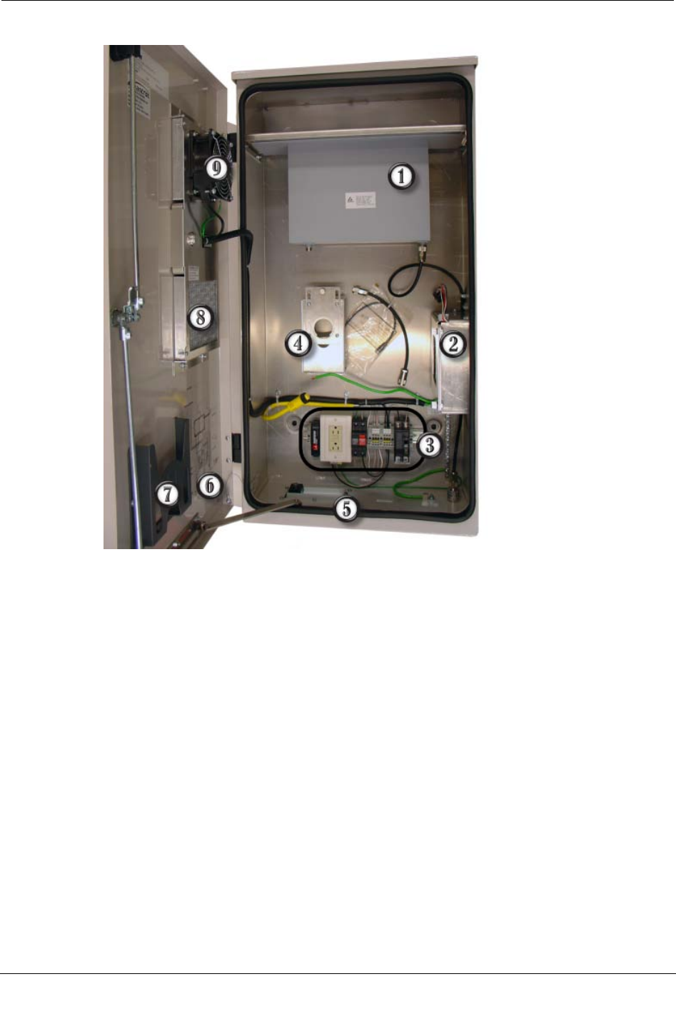
TCU Components
1 RF Filter
2 Battery
3 Surge protection devices (SPDs), receptacle, terminal blocks
4 CCU mounting plate
5 Roxtec™ block
6 Wiring diagram
7 Document holder
8 Air filters There are two air filters, one shown at (8) and another behind the fan (9).
9 Fan
Tower Installation
CCU 100 and Repeater 100 Installation Guide 39
Proprietary and Confidential
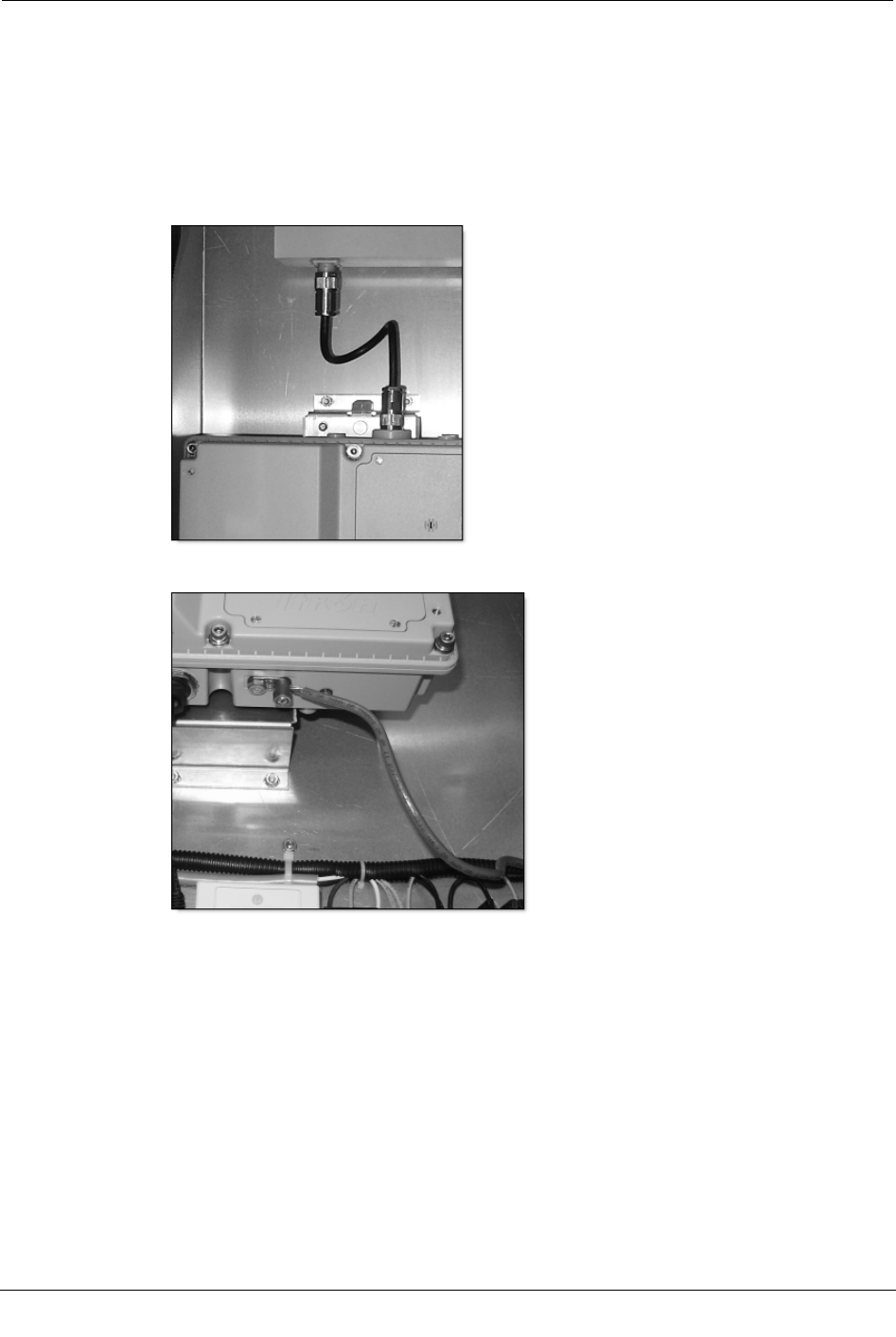
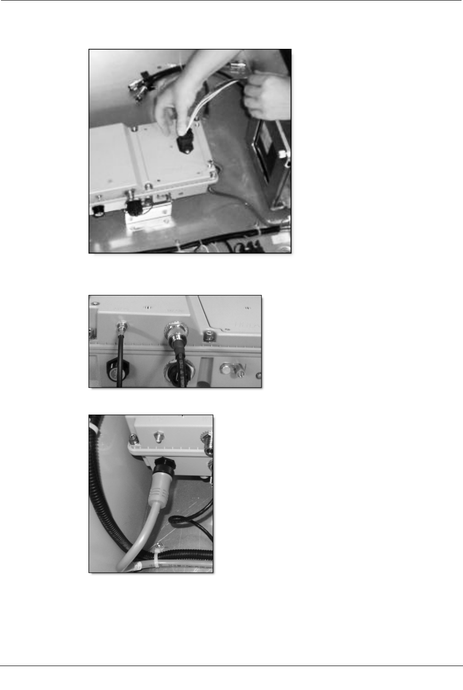
To assemble the Tower CCU 100
1. Attach CCU to CCU mounting plate.
a. Insert the CCU mounting disc into the mounting plate keyhole.
b. Slide the CCU down until you feel it click into place.
2. Connect cable from CCU to RF filter.
3. Connect ground wire to CCU.
Chapter 3 Installing the CCU/Repeater
40 CCU 100 and Repeater 100 Installation Guide
Proprietary and Confidential
4. (optional) Connect the Ethernet cable to the CCU and the top of the 10/100 BT SPD.
Feed the external Ethernet cable through the Roxtec block and connect it to the
bottom of the 10/100 BT SPD.
Instructions for using a Roxtec Block are supplied in the TCU cabinet.
Tower Installation
CCU 100 and Repeater 100 Installation Guide 41
Proprietary and Confidential
5. Connect the battery to the connector on the battery door of the CCU.
The battery door connection is only present on CCUs designed for TCU installations.
6. Feed the GPS and WAN (if required) antenna cables through the Roxtec block and
connect them to the CCU.
7. Connect the power cable to the CCU.
8. See Attaching the External GPS/WAN Antennas on page 18 for instructions on
installing the antennas.
9. Connect power to the cabinet. See the wiring diagram on the inside of the cabinet
door.
Chapter 3 Installing the CCU/Repeater
42 CCU 100 and Repeater 100 Installation Guide
Proprietary and Confidential
AC Tower Installation Diagram
Solar Powered Installation
CCU 100 and Repeater 100 Installation Guide 43
Proprietary and Confidential
Solar Powered Installation
All coaxial cable connections must be properly weather-proofed per industry standards
unless otherwise specified. This includes any connections for the antennas and the
CCU/Repeater. If the CCU/Repeater is installed indoors, only the connections located
outside must be weather-proofed.
Warning Before installing a CCU/Repeater, ensure that the selected location
can support the weight of the CCU/Repeater, mounting hardware, solar panels,
and batteries. A thorough structural analysis should be performed by a qualified
engineer at your desired location prior to installation. Itron is not responsible for
improper installations or for installations at a site that cannot adequately support
the CCU/Repeater.
Because of the size and weight of the solar system, Itron recommends that more than one
person be present for the installation.
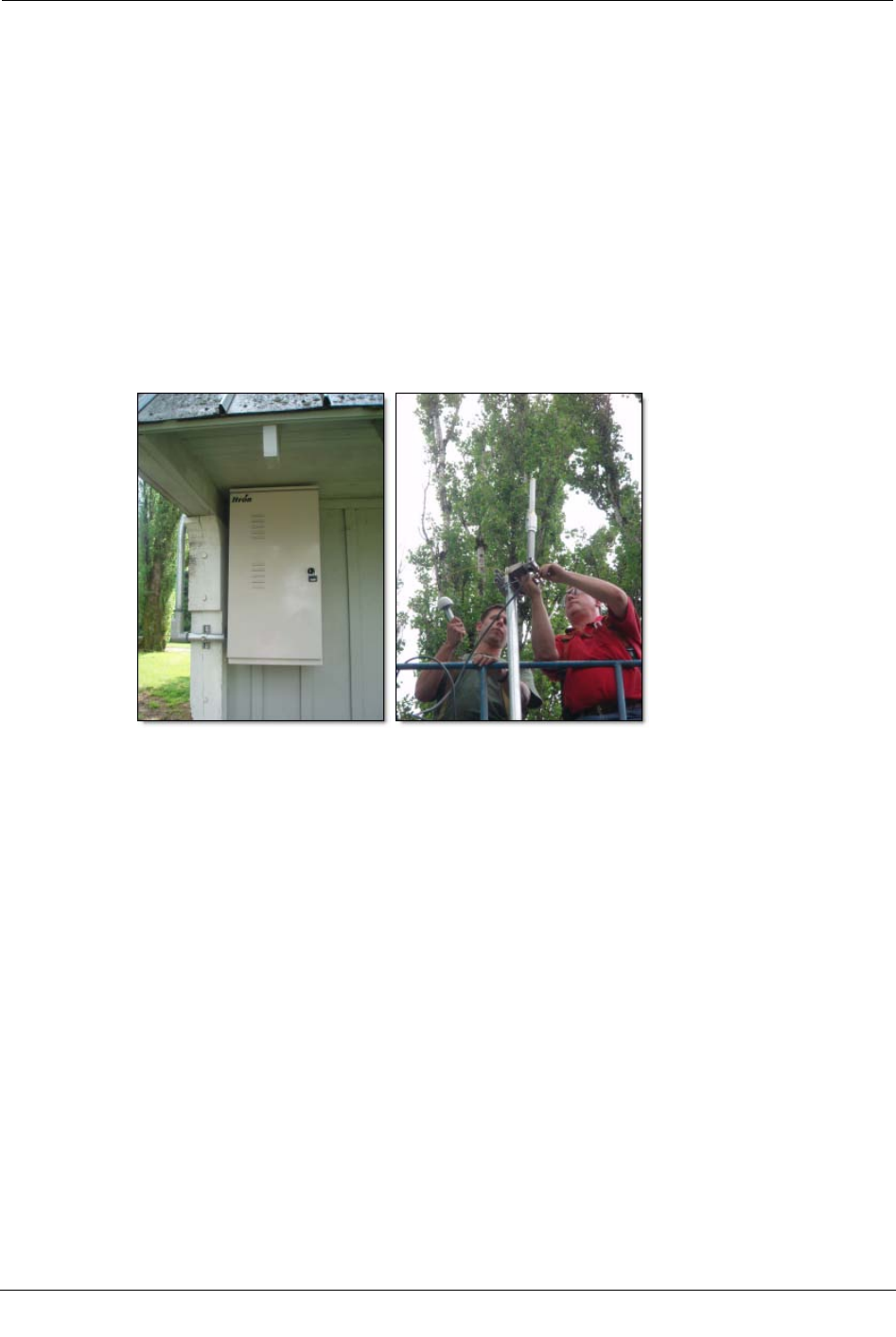
Solar Installation Overview
The Solar CCU/Repeater installation differs slightly from other CCU 100 installation
profiles in that the power comes from a separate cabinet enclosure which houses the solar
controller and batteries.
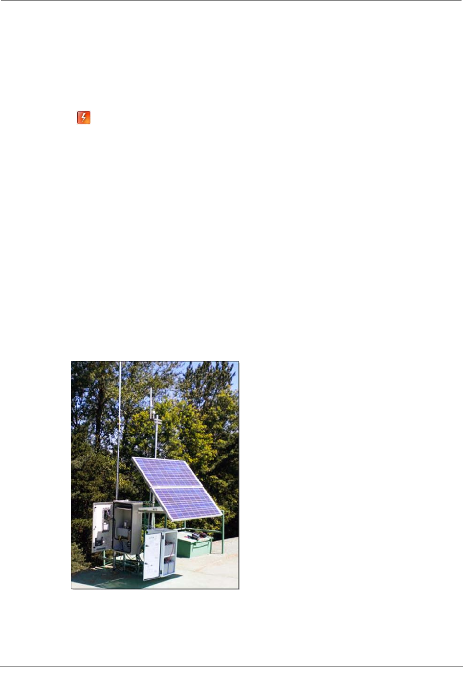
The Solar CCU/Repeater is mounted like other CCU/Repeaters, but the power comes
from the solar cabinet which houses the solar controller and batteries. The picture below
shows a solar tower installation.
Chapter 3 Installing the CCU/Repeater
44 CCU 100 and Repeater 100 Installation Guide
Proprietary and Confidential
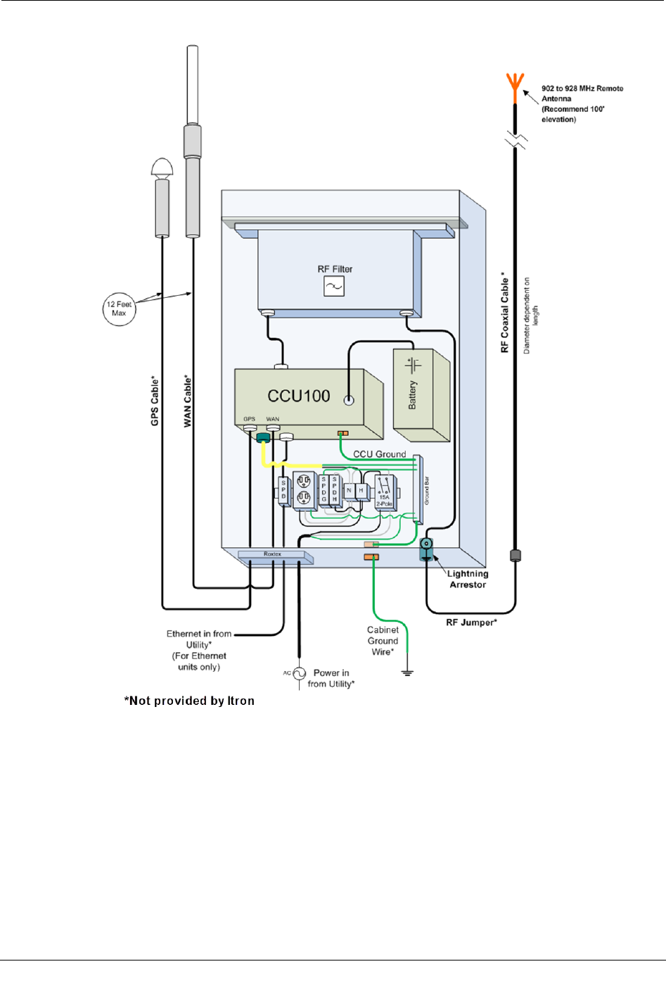
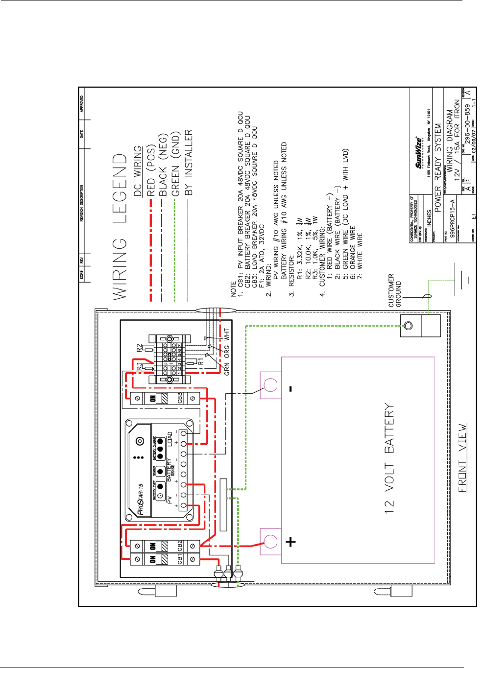
Solar Wiring Diagram
The diagram below illustrates how a solar panel system must be wired to connect to the
CCU/Repeater. This enclosure is pre-wired. You are required to connect only the power
and the ground.

Solar Powered Installation
CCU 100 and Repeater 100 Installation Guide 45
Proprietary and Confidential
To assemble the Solar CCU 100
1. Mount the solar panels and battery box as described in the Installation, Operation,
and Maintenance Manual supplied with the solar system.
2. Wire the five conductor power cable to the solar cabinet, as shown in the Solar
Wiring Diagram on page 44. Use the watertight grommet supplied with the solar
cabinet.
3. Mount the CCU/Repeater in the desired location.
Note The supplied power cable from the solar battery box to the CCU/Repeater is
only 12 feet long.
4. Connect ground wire to CCU.
5. If required, connect the antenna and Ethernet cables to the CCU/Repeater.
6. Connect the battery to the CCU.
7. Connect the power cable to the CCU.
8. See Attaching the Remote Antennas on page 18 for instructions on installing the
antennas.
Chapter 3 Installing the CCU/Repeater
46 CCU 100 and Repeater 100 Installation Guide
Proprietary and Confidential
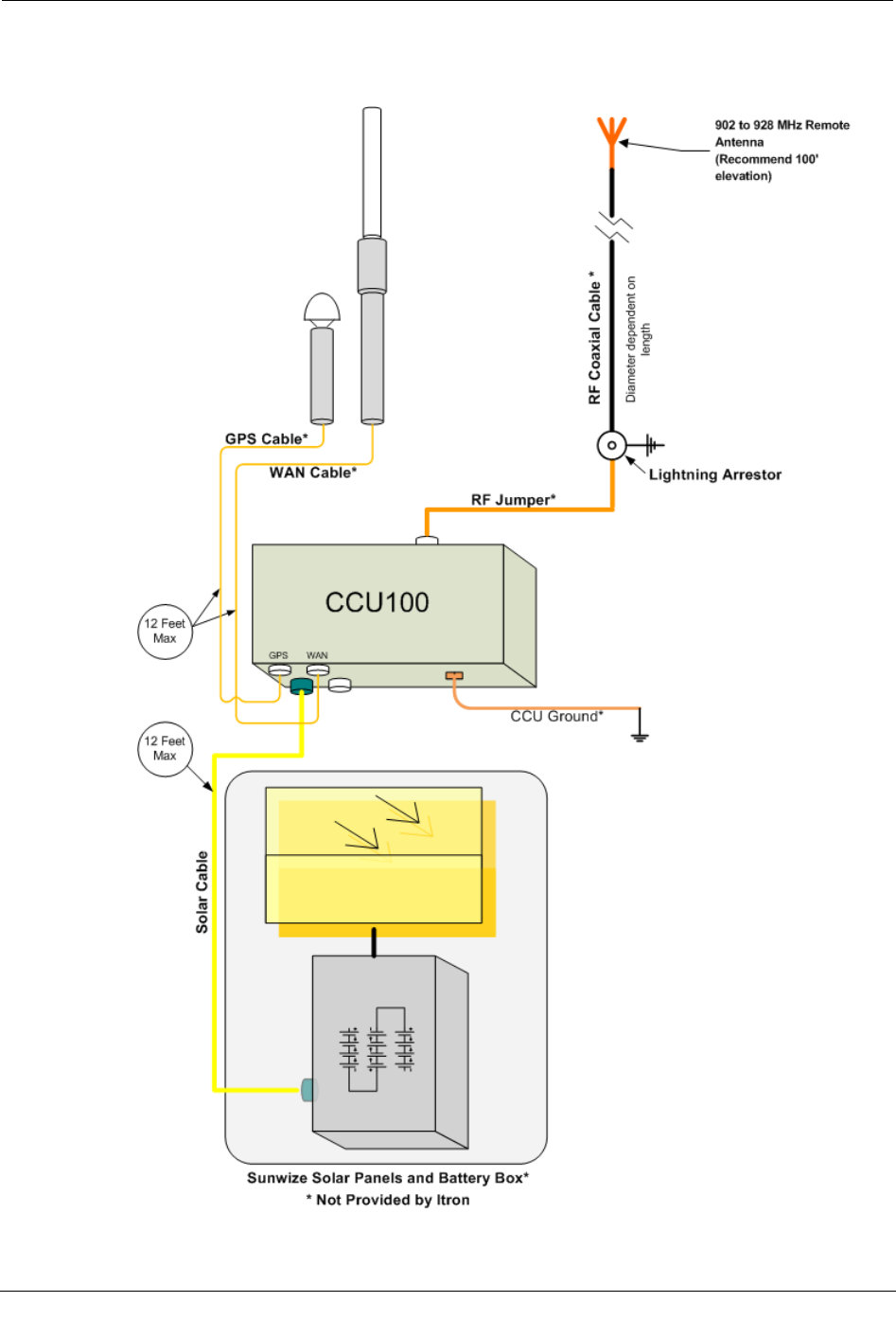
Solar Installation Diagram
The diagram below shows a typical solar powered installation.

CCU 100 and Repeater 100 Installation Guide 47
Proprietary and Confidential
In this chapter, you will learn how to perform field maintenance on the CCU/Repeater
battery. With some routine care, the batteries used by CCUs/Repeaters will perform at
optimal levels for several years.
The following sections show you how to store and charge spare CCU/Repeater batteries,
as well as how to replace a CCU/Repeater battery in the field.
Shipping Requirements
Warning! Electrical fire hazard—protect against shorting.
Terminals can short circuit and cause a fire if not insulated during shipping.
Requirements for shipping batteries:
• Batteries must be labeled "NONSPILLABLE" during shipping. Follow all federal shipping
regulations. See CFR 49 Parts 171 through 180, available online at www.gpoaccess.gov
• Batteries must have short circuit protection during shipping. Exposed terminals, connectors, or
lead wires must be insulated with a durable inert material to prevent exposure during shipping.
Failure to comply with these requirements can cause a fire during shipping and
handling.
CHAPTER 4
Battery Care and Replacement
Chapter 4 Battery Care and Replacement
48 CCU 100 and Repeater 100 Installation Guide
Proprietary and Confidential
Battery Storage and Charging
To ensure maximum lifespan and efficiency from your CCU/Repeater batteries, Itron
recommends the following storage and maintenance procedures.
Long-Term Storage
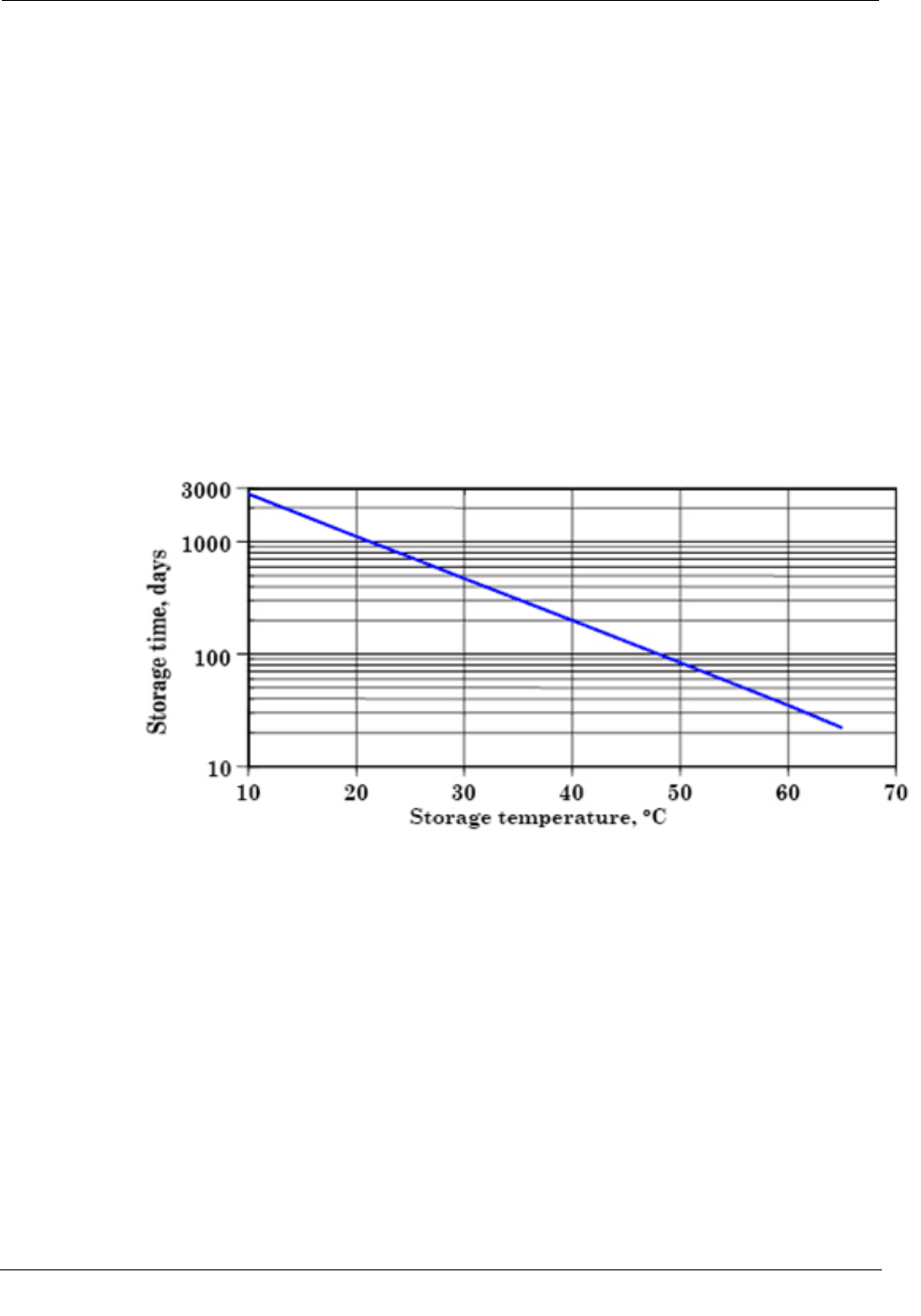
Batteries may be stored for up to two years at room temperature (25°C or 77°F), and then
may be recharged with no loss in cell reliability or performance capabilities. The example
storage time versus temperature chart below is a plot of maximum storage time as a
function of storage temperature. This curve shows the maximum number of days at any
given temperature, from 10°C (50°F) to 65°C (149°F), for the battery to discharge from a
fully charged state of about 6.42 volts (2.14 volts per cell) down to a zero charge state of
5.79 volts or (1.93 volts per cell). The battery should not be allowed to discharge below
5.79 volts because of the danger of damaging the performance characteristics of the
battery permanently.
When batteries are stored at or near 25°C (77°F) it is recommend to conduct an open
circuit voltage (OCV) audit every six months and recharge when OCV readings approach
6 volts (2.00 volts per cell). If storage temperatures are significantly higher than 25°C
(77°F), even for short durations, the frequency of OCV audits must increase.
It is important to recognize that the self-discharge rate of the battery is non-linear. The
rate of self-discharge changes as the state of charge (SOC) of the battery changes. The
time taken for a battery to discharge from a 100% SOC to 90% SOC is different from the
time it takes to self-discharge from a 20% SOC to a 10% SOC.
Battery Storage and Charging
CCU 100 and Repeater 100 Installation Guide 49
Proprietary and Confidential
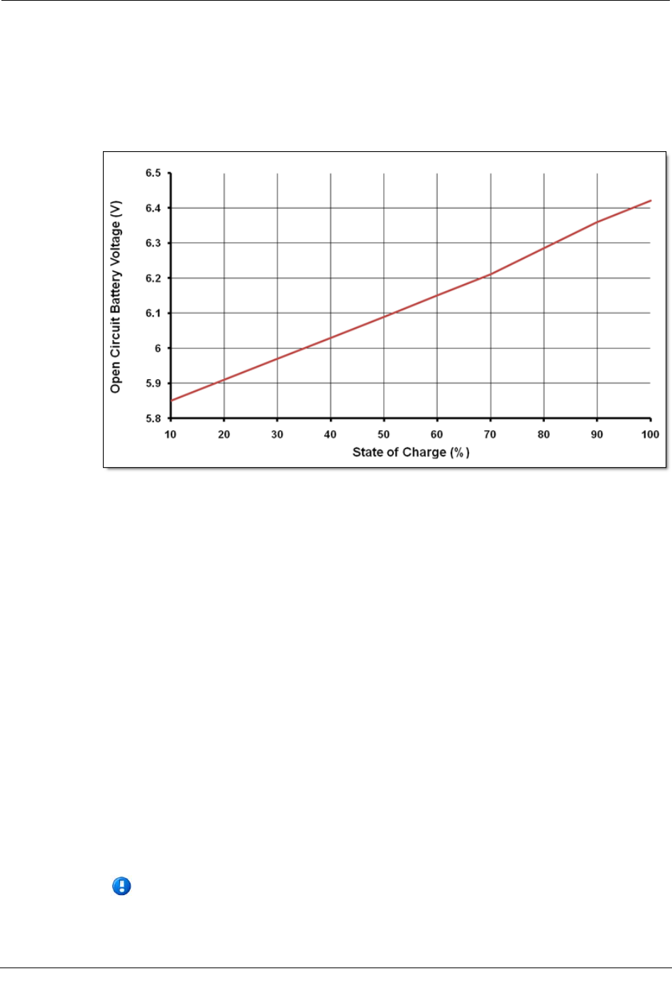
State of Charge
The state of charge (SOC) of the battery can be approximated by using the curve shown in
the chart below. This curve is accurate to within 20% of the true SOC of the cell under
consideration, if it has not been charged or discharged within the past 24 hours. The curve
is accurate to within 5% if the cell has not seen any activity, charge or discharge, for the
past five days.
Charge the Battery
You can charge spare CCU/Repeater batteries individually or in groups to save time.
When charging batteries, there are several items you need:
• Power Sonic PSC-61000A-C charger
• Molex 39-01-4046 connector
• CCU/Repeater batteries
The recommended method for charging the batteries is to utilize the Power Sonic PSC-
61000A-C charger. The Power Sonic charger needs to be modified so that it can be
plugged directly into the battery. This is done by retrofitting the output of the charger to a
Molex 39-01-4046 connector with the red wire going to pin one and the black wire going
to pin two of the connector. Follow the instructions that come with the charger for correct
operation.
After charging, the battery should be removed from the charger for at least 24 hours. After
this time the open circuit voltage should be measured to verify that it is at or above 6.4
volts.
Note Batteries in storage need to be charged routinely for maximum shelf life. For
more information, see Long Term Storage on page 48.
Chapter 4 Battery Care and Replacement
50 CCU 100 and Repeater 100 Installation Guide
Proprietary and Confidential
Battery Service Life
All batteries have extremely variable service life, depending upon the type of cycle,
environment, and charge to which the cell or battery is subjected during its life. There are
two basic types of service life: cycle life and calendar life. The battery in the
CCU/Repeater is called in to service only during power outages, so in this case only
calendar (or float) life is applicable.
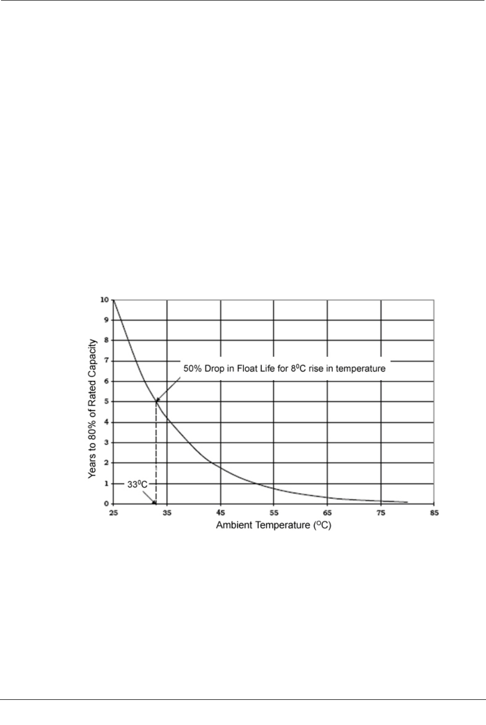
Calendar Life
The design calendar (or float) life of the battery is up to eight to ten years at room
temperature (25°C/77°F) and under proper charging conditions.
This design life has been confirmed by the use of accelerated testing methods that are
widely accepted by both manufacturers and users of sealed-lead batteries. High
temperatures are used to accelerate the aging process of the battery under test.
The float life of a cell is cut in half for roughly every 8°C (14.4°F) rise in ambient
temperature. The example below shows the relationship between ambient temperature and
float life for batteries that have a float life of ten years at 25°C (77°F).
A ten year battery lasts for five years at 33°C (91.4°F) and only 2½ years at 41°C
(105.8°F).
Preventative Maintenance
Itron recommends a preventative maintenance cycle of a two-year replacement in extreme
environments (average temperatures greater than 110°F/44°C), or five years in non-
extreme environments (average temperatures less then 90°F/31°C).

Replacing the Integrated Battery
CCU 100 and Repeater 100 Installation Guide 51
Proprietary and Confidential
Replacing the Integrated Battery
The following procedure shows you how to replace the integrated battery once it has been
installed in the field.
Warning Risk of explosion if battery is replaced by an incorrect type. Always
replace with Itron part number BAT-0045-001.
For information on battery disposal or recycling, contact EnerSys at 1.800.363.7797 or
recycling@enersys.com.
To replace the battery
1. Remove the battery compartment cover by loosening the four screws securing it.
2. Slide the battery out of the battery compartment.
3. Carefully, disconnect the four pin connector.
4. Connect the new battery's four pin connector.
5. Slide the new battery into the battery compartment.
6. Replace the battery compartment cover, and torque the screws to 6 inch-pounds.

Chapter 4 Battery Care and Replacement
52 CCU 100 and Repeater 100 Installation Guide
Proprietary and Confidential
CCU 100 and Repeater 100 Installation Guide 53
Proprietary and Confidential
CCU/Repeater Dimensions and Weight
Weight is shown in pounds and dimensions are shown in inches.
Component
Weight
CCU/Repeater 7 lbs
AC tower unit 76 lbs
External GPS/WAN antenna system 6 lbs
Remote 900 MHz antenna system 3.5 lbs
900 MHz antenna (standard, unity gain) 1 lb
Pole mounting kit 3 lbs
Wall mounting kit 2 lbs
APPENDIX A
Detailed CCU/Repeater Specifications
Appendix A Detailed CCU/Repeater Specifications
54 CCU 100 and Repeater 100 Installation Guide
Proprietary and Confidential
CCU/Repeater Dimensions and Weight
CCU 100 and Repeater 100 Installation Guide 55
Proprietary and Confidential
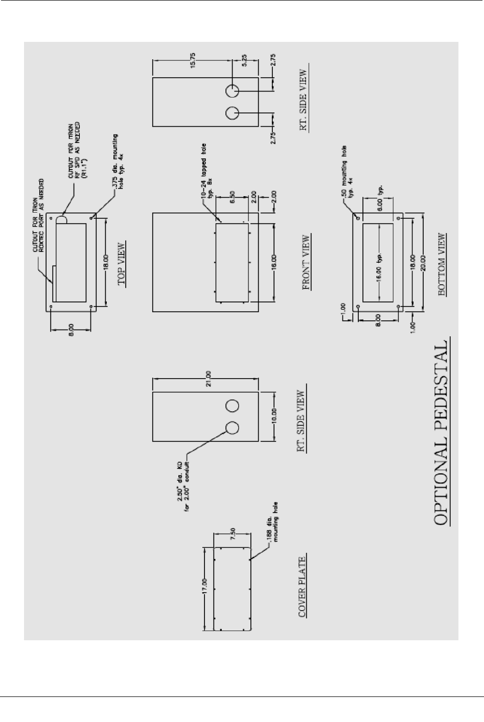
The illustration below shows the dimensions for the optional pedestal unit. This unit ships
with a gasket and fasteners to attach the cabinet to the pedestal.

Appendix A Detailed CCU/Repeater Specifications
56 CCU 100 and Repeater 100 Installation Guide
Proprietary and Confidential
Antenna Specifications
Specifications for the 900 MHz, GPS, and WAN antennas are shown in the following
tables.
Important All coaxial cable connections must be properly weather-proofed per
industry standards unless otherwise specified. This includes any connections for the
antennas and the CCU/Repeater components. If the CCU/Repeater is installed
indoors, only the connections located outside need to be weather-proofed.
This device has been designed to operate with the antennas listed below. Antennas not
included in this list are strictly prohibited for use with this device. The required antenna
impedance is 50 ohms.
900 MHz antennas
Specification Standard 5 dBi
High gain (8.15 dBi)
Part number MSE-0330-001 MSE-0372-001
Gain 3 dBd (5.15 dBi) 6.0 dBd (8.15 dBi)
Horizontal beamwidth Omnidirectional Omnidirectional
Vertical beamwidth -3dB minimum, +/- 16 degrees from
horizontal
17 degrees
Electrical downtilt available 0 degrees 0 degrees
Power rating 50W 100W
Impedance 50 ohms 50 ohms
Termination Type N male Type N female
Lightning protection Direct ground Direct ground
Overall length 18 in. 65 in.
Radome diameter 1.00 in. OD 1.310 in. OD
Mounting area length n/a ~8 in.
Weight (without clamps) 1 lb. 3 lbs.
Maximum wind speed 160 mph 125 mph
Wind load @ rated wind
speed
n/a 57 lbs.

Antenna Specifications
CCU 100 and Repeater 100 Installation Guide 57
Proprietary and Confidential
GPS/WAN antennas
Specification
GPS
WAN
Part number MSE-0260-001 MSE-259-001
Gain 30 dB 0 dBd (806-896)
3dBd (1850-1990)
Horizontal beamwidth Omnidirectional Omnidirectional
Power rating N/A 100 W
Impedance 50 ohms 50 ohms
Termination Type TNC female Type N female
Frequency 1575.42 MHz 806-896 MHz
1850-1990 MHz
Polarization RHCP Vertical
Prime power 3.3 V DC N/A
Overall length 2.61 in. 13.75 in.
Radome diameter 3.05 in. 1.310 in.
Weight 6 oz. < 1.0 lb.
For the latest antenna part numbers, see the Fixed Network 100 Ordering Guide or contact
your Itron representative.
To reduce potential radio interference to other users, the antenna type and its gain should
be so chosen that the equivalent isotropically radiated power (e.i.r.p.) is not more than that
permitted for successful communication.
Industry Canada Conformity
This radio transmitter (IC: 864A-CCU100, IC:864A-CCU100A, IC:864A-CCU100B
and IC:864A-CCU100T, IC:864A-CCU100TA, IC:864A-CCU100TB) has been
approved by Industry Canada to operate with the antenna types listed above with the
maximum permissible gain and required antenna impedance for each antenna type
indicated. Antenna types not included in this list, having a gain greater than the
maximum gain indicated for that type, are strictly prohibited for use with this device.
Le présent émetteur radio (IC: 864A-CCU100, IC:864A-CCU100A, IC:864A-
CCU100B et IC:864A-CCU100T, IC:864A-CCU100TA, IC:864A-CCU100TB) a été
approuvé par Industrie Canada pour fonctionner avec les types d'antenne énumérés ci-
dessus et ayant un gain admissible maximal et l'impédance requise pour chaque type
d'antenne. Les types d'antenne non inclus dans cette liste, ou dont le gain est supérieur
au gain maximal indiqué, sont strictement interdits pour l'exploitation de l'émetteur.

Appendix A Detailed CCU/Repeater Specifications
58 CCU 100 and Repeater 100 Installation Guide
Proprietary and Confidential
Environmental Specifications
The following environmental specifications are associated with a CCU/Repeater.
Specification
Value
Operating temperature Components
GPS/WAN antenna system: -33° C to 60° C
CCU/Repeater: -33° C to 60° C
Storage temperature -40° C to 85° C
Note Batteries may be stored for up to two years at 25° C
without periodic recharging. When batteries are stored at this
temperature, an open circuit voltage audit should be conducted
every six months.
If the storage temperature is significantly higher than 25° C, the
frequency of the audits must be increased.
Humidity 0 to 90% non-condensing
Transmitter
Detailed specifications for the CCU/Repeater transmitter are described in the following
table.
Specification
Value
Maximum transmit power at antenna 29.5 dBm
Frequency 903.0 MHz to 926.8 MHz (USA)
CCU/Repeater Power Operating Range
Specification
Value
Voltage (AC) 90 VAC to 265 VAC
Voltage (DC) +12 VDC typical
+11.7 VDC minimum
+17.0 VDC maximum
Frequency 47 Hz to 63 Hz
Average power 10 Watts (battery trickle charge)
Peak power 50 Watts

Battery Pack
CCU 100 and Repeater 100 Installation Guide 59
Proprietary and Confidential
Battery Pack
The battery pack is contained in its own compartment. The battery pack is a three-cell,
sealed, lead acid battery pack (6V, 4.5 amp-hours) that is field replaceable and designed
to last five years under normal circumstances. To ensure minimal impact upon battery
life, a preventative maintenance schedule of two year replacement is required in an
extreme environment, such as a desert installation. Normal preventative maintenance is
every five years for non-hot environment installations.
Warning Risk of explosion if battery is replaced by an incorrect type. Always
replace with Itron part number BAT-0045-001.
The batteries can power the system for a duration of 90 minutes in the case of a power
outage.
If
Then
AC power fails The CCU/Repeater battery pack maintains system functions for
approximately 90 minutes. A message indicating the AC failure
is sent to the Network Software.
AC power is restored A message is sent to the Network Software indicating that AC
power has been restored.
The battery pack specifications are listed below.
Specification
Value
Type Sealed-lead acid, rechargeable
Power 6V, 4.5 amp-hours
Life Five years at 33° C. Battery life decreases by 50% for each 8° C
rise in temperature above 25°C.
Charge time 10 hours at 25° C
The battery in the CCU/Repeater uses three EnerSys Cyclon lead-acid cells connected in
series to provide a nominal voltage of 6 volts. The battery is terminated with a four
position Molex connector (Molex P/N #39-01-4041) with the following pinout:
Pin #
Wire Color
Signal
1 Red +V BATT
2 Black Ground
3 White Thermistor
4 White Thermistor
For information on battery disposal/recycling contact EnerSys at 1.800.363.7797 or
recycling@enersys.com.

Appendix A Detailed CCU/Repeater Specifications
60 CCU 100 and Repeater 100 Installation Guide
Proprietary and Confidential

CCU 100 and Repeater 100 Installation Guide 61
Proprietary and Confidential
Status Indicator
The LED Status Indicator is primarily intended to support installation personnel for
immediate feedback. The following sequences define the Fixed Network solution's
operational characteristics:
Sequence details: The dot time: 100 mSec
The dash time is 300 mSec
Off Time between B and N: 700 mSec
Off time between dot and dash: 100 mSec
CCU State
Description
LED Pattern
Off The CCU is not running Off
Powered
(Host booting)
When power has been applied to the CCU and
the CCU reset has been released allowing the
boot operation to begin.
Solid continuous illumination
Time Acquisition The CCU is attempting to synchronize its
system time with an external time reference
through NTP and / or GPS.
Note Repeaters do not support NTP. Instead,
repeaters acquire time from either the CCU or
from GPS. If time is received from the CCU,
the repeater status indicator will not display the
Morse T.
Morse code for the letter ‘T’ ( _ ). A single
660 ms flash repeated every 10 seconds.
Starting The Linux kernel has been loaded and
initialized and the CCU application begins
execution
Morse code for the letter ‘P’ ( . _ _ . ) with the
dits at 220 ms the dahs at 660 ms and 220 ms
spacing between the dits and dah. Repeated
every 10 seconds.
ERT Heard The radio processor has booted and is
reporting end-point messages to the host
processor
Morse code for the letter ‘N’ ( _ . )
Headend
Connected
The CCU has established an authenticated
connection with the head-end over the
configured WAN interface.
Morse code for the letter ‘B’ ( _ . . . )
No Battery The CCU has determined that it should have a
backup battery but that battery does not appear
to be present or is not functioning. The display
of this state is a higher priority than states other
than Low-visibility and will be displayed
exclusively if the battery cannot be detected.
Morse code for the letter ‘S’ ( . . . )
APPENDIX B
Status and Diagnostics

Appendix B Status and Diagnostics
62 CCU 100 and Repeater 100 Installation Guide
Proprietary and Confidential
CCU State
Description
LED Pattern
Ok The radio processor has booted and is
reporting end-point messages to the host
processor and the CCU has established an
authenticated connection to the head-end. This
condition will be signaled for about 15 minutes
before moving the "low-visibility" state.
Morse code for the letter sequence ‘BN’ ( _ . .
. _ . ) The dit and dah timing described above
with the space between the ‘B’ and the ‘N’
characters being 660 ms.
Token Received If the radio reports decoding a "magic" token
which would enable the WiFi diagnostic
interface this pattern is presented for one 10
second interval. This condition is higher
priority than the Lo-visibility and the missing
battery indications.
Morse code for the number ‘5’ ( . . . . . ).
Low-visibility After 15 minutes in the "Ready" state the LED
pattern changes to the "Low-visibility" mode
which indicates that the CCU is running (does
not imply that end-points are still being read or
that head-end communications are still
possible.
10 ms illumination every 30 seconds.
Performing an Antenna Sweep Test
If the 900 MHz antenna is remotely mounted for your installation, an antenna sweep test
must be performed to verify that the antenna functions within acceptable tolerances at
your installation site.
This test should be performed under the following conditions:
• Beginning Frequency: 902
• Ending Frequency: 928
• VSWR Expected Results: Must be 1.5 or less for the specified frequency band.
• Return Loss: Must be –18dB or better for the specified frequency band. Any
deviations from this return loss warrant further investigation.
• Test Point: Feed line connected to the antenna at the top; test from the lightning (or
surge) arrestor to the antenna port.
• Results: Test results must be saved in. PDF format.
• Test Gear: Current and proper calibration; be sure that calibration is turned on during
the test. A qualified operator of the test equipment must perform the test.
Note If the system does not perform to the above test specifications, the reasons for
system failure and possible remedies must be identified before leaving the
installation site.

CCU 100 and Repeater 100 Installation Guide 63
Proprietary and Confidential
A
AC service requirements • 9
antenna placement • 10
antenna specifications • 56
antennas • 4, 5, 10, 11, 12, 18, 19, 56, 62
attaching the CCU/Repeater • 21
attaching the direct mount antenna • 19
attaching the remote antennas • 18
B
battery • 34, 48
battery pack • 34, 59
battery storage • 48
brackets • 15, 21
C
calendar life • 50
CCU configuration • 1
CCU power operating range • 58
CCU specifications • 53
charging • 48
coaxial cable • 13
components • 2
connecting cables • 29
connectors • 15
D
davit arm mount • 27
dimensions • 53
E
endpoint antenna • 5, 10, 11, 12, 18, 19, 56, 62
environmental specifications • 58
Ethernet connections • 9
external Ethernet connections • 9
F
ferrite bead • 34
G
GPS antenna • 4, 8, 11, 12, 18, 56, 62
GPS coverage • 8
grounding • 1, 5, 11, 12, 13, 56
I
installation profiles • 7
installing the battery • 32
installing the CCU/Repeater • 17
L
lightning arrestor • 12
long-term storage • 48
M
mains powered installation • 13
maintenance • 47
materials not provided by Itron • 13
module • 2
mounting hardware • 15, 21
mounting holes • 53
O
operating range • 58
P
pedestal dimensions • 53
performing an antenna sweep test • 62
pipe mount • 22
planning • 7
pole mount • 24
power operating range • 58
preventative maintenance • 50
profiles • 7, 13, 43
propagation study • 8
providing power • 35
R
remote antenna placement • 10
remote antennas • 4, 5, 10, 11, 12, 18, 56, 62
Repeater power operating range • 58
Repeater specifications • 53
replacing the battery • 51
S
service life • 50
Index

Index
64 CCU 100 and Repeater 100 Installation Guide
Proprietary and Confidential
shipping requirements • 47
site selection • 8
siting • 8
solar installation diagram • 46
solar powered installation • 43
solar wiring diagram • 44
specifications • 53, 56, 58
state of charge • 49
status indicator • 61
storage • 48
T
TCU mounting holes • 53
transmitter • 58
W
wall mount • 26
WAN antenna • 4, 8, 11, 12, 18, 56, 62
WAN coverage • 8
weatherization • 29