Users Manual

T
Repeater
Installation Guide
For use with the Fixed Network and Mobile
Collection solutions
D R A F T

ii Repeater Installation Guide
TDC-0613-003b 03/06 DRAFT
Identification
Repeater Installation Guide
TDC-0613-003b 03/06
For use with the Fixed Network and Mobile Collection solutions
Trademark Notice
Itron is a registered trademark of Itron, Inc.
All other product names and logos in this document are used for identification purposes only and may be trademarks or registered
trademarks of their respective companies.
Copyright Notice
Your company has the right to reproduce this contract document provided that such reproduction shall be subject to the same use
and disclosure restrictions contained in the Confidentiality and Non-Disclosure paragraphs in the Sales Contract.
© 2004-2006 Itron, Inc. All rights reserved.
Compliance Statement
This equipment has been tested and found to comply with the limits for a Class B digital device, pursuant to Part 15 of the FCC
Rules. These limits are designed to provide reasonable protection against harmful interference in a residential installation. This
equipment generates, uses, and can radiate radio frequency energy and, if not installed and used in accordance with the
instructions, may cause harmful interference to radio communications. However, there is no guarantee that interference will not
occur in a particular installation.
If this equipment does cause harmful interference to radio or television reception, which can be determined by turning the
equipment off and on, the user is encouraged to try to correct the interference by one or more of the following measures:
• Reorient or relocate the receiving antenna.
• Increase the separation between the equipment and receiver.
• Connect the equipment into an outlet on a circuit different from that to which the receiver is connected.
• Consult the dealer or an experienced radio or TV technician for help.
This device complies with Subpart C of Part 15 of FCC Rules. Operation of this device is subject to the following two conditions:
• This device may not cause harmful interference.
• This device must accept any interference that may cause undesirable operation.
This device complies with Part 15.247 of the FCC rules governing spread spectrum devices. The device operates in the 900 MHz
unlicensed band at a maximum peak power level of 1 watt with a transmission duration that will not exceed 50 milliseconds.
This device must be permanently mounted such that it retains a distance of 20 centimeters (7.9 inches) from all persons in order
to comply with FCC RF exposure levels.
Modification and Repairs
To ensure FCC compliance and system performance, this device, antenna and coaxial assembly shall not be changed or modified
without the expressed approval of Itron. Any modification may void the user’s authority to operate the equipment.
Meter Installation/Removal
In the event of malfunction, all repairs should be performed by Itron. It is the responsibility of users requiring service to report
the need for service to Itron.
Customer Service
If you have questions, comments or suggestions contact Itron as follows:
• Mail: Itron, Inc.; Attention: Customer Care; 2818 N. Sullivan Road; Spokane, WA 99216
• E-mail: support@itron.com
• Phone: 1-800-635-8725
WARNING! This device contains no user serviceable parts. Attempts to repair this device by unauthorized personnel may
subject the person to shock hazard if removal of protective covers is attempted. Unauthorized repair may void the warranty
and/or maintenance contract with your company.
WARNING! The installation of this device may subject the installer to hazardous conditions, including the possibility of
electrical shock. Trained professionals should install this device. This instruction manual should be considered supple-
mental and used in addition to and in accordance with your company’s meter installation and removal procedures and all
related safety regulations.

DRAFT Contents iii
TDC-0613-003b 03/06
Contents
List of Procedures. . . . . . . . . . . . . . . . . . . . . . . . . . . . . . . . . . . . . . . . . . . v
Before You Begin . . . . . . . . . . . . . . . . . . . . . . . . . . . . . . . . . . . . . . . . . . vii
Overview . . . . . . . . . . . . . . . . . . . . . . . . . . . . . . . . . . . . . . . . . . . . . . vii
Audience . . . . . . . . . . . . . . . . . . . . . . . . . . . . . . . . . . . . . . . . . . . . . . vii
How This Document is Organized . . . . . . . . . . . . . . . . . . . . . . . . . . . vii
Documentation Conventions . . . . . . . . . . . . . . . . . . . . . . . . . . . . . . . vii
Chapter 1 Getting Started. . . . . . . . . . . . . . . . . . . . . . . . . . . . . . . . . . . . . . . . . . . . . . 1
What is a Repeater? . . . . . . . . . . . . . . . . . . . . . . . . . . . . . . . . . . . . . . . . . . 1
Overview . . . . . . . . . . . . . . . . . . . . . . . . . . . . . . . . . . . . . . . . . . . . . . . 1
Repeater Identification . . . . . . . . . . . . . . . . . . . . . . . . . . . . . . . . . . . . . 1
Repeater Types . . . . . . . . . . . . . . . . . . . . . . . . . . . . . . . . . . . . . . . . . . 1
Repeater Specifications . . . . . . . . . . . . . . . . . . . . . . . . . . . . . . . . . . . . 2
Planning for Repeater Installations . . . . . . . . . . . . . . . . . . . . . . . . . . . . . . . 6
Installation Types . . . . . . . . . . . . . . . . . . . . . . . . . . . . . . . . . . . . . . . . . 6
Unpacking the Repeater . . . . . . . . . . . . . . . . . . . . . . . . . . . . . . . . . . . . . . . 6
Overview . . . . . . . . . . . . . . . . . . . . . . . . . . . . . . . . . . . . . . . . . . . . . . . 6
What’s In the Box . . . . . . . . . . . . . . . . . . . . . . . . . . . . . . . . . . . . . . . . . 6
Chapter 2 Single-Channel Repeater Installation . . . . . . . . . . . . . . . . . . . . . . . . . . . 7
Getting Started . . . . . . . . . . . . . . . . . . . . . . . . . . . . . . . . . . . . . . . . . . . . . . 7
Overview . . . . . . . . . . . . . . . . . . . . . . . . . . . . . . . . . . . . . . . . . . . . . . . 7
Installing Pole-Mount Repeaters . . . . . . . . . . . . . . . . . . . . . . . . . . . . . . . . . 7
Overview . . . . . . . . . . . . . . . . . . . . . . . . . . . . . . . . . . . . . . . . . . . . . . . 7
Required Hardware and Tools . . . . . . . . . . . . . . . . . . . . . . . . . . . . . . . 7
Earth Grounding. . . . . . . . . . . . . . . . . . . . . . . . . . . . . . . . . . . . . . . . . . 8
Wind Load . . . . . . . . . . . . . . . . . . . . . . . . . . . . . . . . . . . . . . . . . . . . . . 8
Installing a Single-Channel Repeater on a Davit . . . . . . . . . . . . . . . . . 8
Installing Sleeve-Mount Repeaters . . . . . . . . . . . . . . . . . . . . . . . . . . . . . . 12
Types of Sleeve- Mount Repeaters . . . . . . . . . . . . . . . . . . . . . . . . . . 12
Required Tools . . . . . . . . . . . . . . . . . . . . . . . . . . . . . . . . . . . . . . . . . . 12
Installing on a Ringless Meter Socket . . . . . . . . . . . . . . . . . . . . . . . . 12
Installing on a Ringed Meter Socket. . . . . . . . . . . . . . . . . . . . . . . . . . 15
Chapter 3 Eight-Channel Repeater Installation . . . . . . . . . . . . . . . . . . . . . . . . . . . 19
Getting Started . . . . . . . . . . . . . . . . . . . . . . . . . . . . . . . . . . . . . . . . . . . . . 19
Overview . . . . . . . . . . . . . . . . . . . . . . . . . . . . . . . . . . . . . . . . . . . . . . 19
Installing Pole-Mount Repeaters . . . . . . . . . . . . . . . . . . . . . . . . . . . . . . . . 19
Overview . . . . . . . . . . . . . . . . . . . . . . . . . . . . . . . . . . . . . . . . . . . . . . 19

DRAFT
iv Repeater Installation Guide
TDC-0613-003b 03/06
Required Hardware and Tools . . . . . . . . . . . . . . . . . . . . . . . . . . . . . . 19
Earth Grounding. . . . . . . . . . . . . . . . . . . . . . . . . . . . . . . . . . . . . . . . . 20
Wind Load . . . . . . . . . . . . . . . . . . . . . . . . . . . . . . . . . . . . . . . . . . . . . 20
Installing an Eight-Channel Repeater on a Davit . . . . . . . . . . . . . . . . 20
Installing Decorative-Mount Repeaters . . . . . . . . . . . . . . . . . . . . . . . . . . . 24
Overview . . . . . . . . . . . . . . . . . . . . . . . . . . . . . . . . . . . . . . . . . . . . . . 24
Installing a Decorative-Mount Repeater. . . . . . . . . . . . . . . . . . . . . . . 24

List of Procedures v
TDC-0613-003b 03/06
DRAFT
List of Procedures
Installing a Decorative-Mount Repeater . . . . . . . . . . . . . . . . . . . . . . . . . . . . . . . . 24
Installing a Single-Channel Repeater on a Davit . . . . . . . . . . . . . . . . . . . . . . . . . . 8
Installing an Eight-Channel Repeater on a Davit . . . . . . . . . . . . . . . . . . . . . . . . . 20
Installing on a Ringed Meter Socket. . . . . . . . . . . . . . . . . . . . . . . . . . . . . . . . . . . 15
Installing on a Ringless Meter Socket . . . . . . . . . . . . . . . . . . . . . . . . . . . . . . . . . 12

DRAFT
vi Repeater Installation Guide
TDC-0613-003b 03/06

Before You Begin
vii
TDC-0613-003b 03/06
Before You Begin
Overview This document describes the installation and configuration of repeaters for the
Fixed Network and Mobile Collection solutions. This document describes the
different types of repeaters; available installation kits and accessories; and the
overall installation process.
Audience This document is intended for utility field personnel and others associated with
the installation and maintenance of a repeater. Installers should have previous
training and experience in the following:
• Installation and maintenance of electric meters
• Electrical wiring and related skills
• All utility-specific OSHA regulations and procedures
How This Document
is Organized This document is organized as the following.
Documentation
Conventions This document uses the following conventions.
Chapter Description
List of Procedures Provides an alphabetical list of all procedures con-
tained in this document.
Chapter 1.
Getting Started Describes what a repeater is, the types of repeaters,
specifications, and the contents of installation kits.
Chapter 2.
Single-Channel
Repeater Installation
Provides step-by-step instructions for installing
single-channel pole-mount and sleeve-mount
repeaters.
Chapter 3. Eight-
Channel Repeater
Installation
Provides step-by-step instructions for installing
eight-channel pole-mount and decorative-mount
repeaters.
Convention Example
Keypresses are in bold. Press Enter when complete.
Menu paths are in bold.From the Start menu, choose File > Save As.
(This example instructs the user to choose File
from the Start menu; then choose Save As from
the File menu.)
viii Repeater Installation Guide
TDC-0613-003b 03/06
CAUTION This type of note warns the user that failure to heed the information in
the note could result in loss of data. Be sure to carefully read a CAUTION note
and heed the advice/instructions.
Computer commands to be
typed by the user are in
Courier New font.
At the C: prompt, type cd itron/bin
File names are in Courier
New font. The data is uploaded to the upload.dat file
Hypertext links are blue.See Contents on page iii for the complete table
of contents.
The last line in a table is
defined by a thick gray
line.
Note the thick gray line below this row. If the
table continues on another page, the column
headings are repeated on each page.
Convention Example
WARNING! This type of note is used to warn of potential physical harm
to the user or hardware. It is critical that you pay strict attention to
WARNING notes, read the information carefully, and heed the
advice/instructions.

DRAFT
Chapter 1 - Getting Started 1
TDC-0613-003b 03/06
Chapter 1
Getting Started
What is a Repeater?
Overview The repeater is a network component that collects data from nearby ERT end-
points and forwards data to a collection device, such as a cell control unit (for
Fixed Network applications) or a Mobile Collector radio (for Mobile Collection
applications).
A repeater expands the footprint of these devices by forwarding data between
endpoints and the CCU or Mobile Collector radio. Single-channel repeaters for-
wards both standard consumption messages (SCM) and interval data messages
(IDM), and eight-channel repeaters forward SCM, IDM, and Type 25 packets
(which are used to indicate positive outage notifications and restorations).
The CCU or MC radio, in turn, communicates the data to the Fixed Network
Collection Engine or Mobile Interface. The CCU or MC radio opens communi-
cation sessions at regular intervals, listening for data from the network repeaters.
The CCU or MC radio then processes returned data according to the default or
custom parameters configured at the Collection Engine or Mobile Interface for
each meter. Repeaters communicate with ERT endpoints and the CCU or MC
radio in the 900 MHz radio band.
Repeater
Identification Each repeater has a unique identification number stored in its internal flash
memory. The ID number is used for remote unit communications, setting the
timing for acknowledgements, setting the index into the transmit, receiving hop
tables at power up, setting the random sequences in the transmit hop table, and
other functions. A repeater does not track other repeaters within its communi-
cation range.
Repeater Types Itron offers two types of repeaters: single-channel and eight-channel. Each type
of repeater can be installed multiple ways.
The type of repeater you install will depend on your site characteristics and
network needs. See Planning for Repeater Installations on page 6 for more
information.
To learn how to install these types of repeaters, see:
•Chapter 2, “Single-Channel Repeater Installation” on page 7
•Chapter 3, “Eight-Channel Repeater Installation” on page 19
DRAFT
2 Repeater Installation Guide
TDC-0613-003b 03/06
What is a Repeater?
Repeater
Specifications Each repeater type (single-channel or eight-channel) and installation option
(pole-, sleeve-, or decorative-mount) has slightly different specifications. See
the tables below for a description of each type of repeater and installation option.
Single-Channel Pole-Mount Repeater
The following table lists the physical specifications for the single-channel, pole-
mount repeater.
Pole-Mount Repeater Specification Description
Power Source Single-phase 240V or 120V AC
Operating and Storage Temperature -40 to +75 C
Storage Temperature -40 to +85 C
Operating humidity 5 to 95% non-condensing relative
humidity
Product identification Numeric and bar coded repeater
module serial number
ANSI Compliance C12.1 standards
Receive/Transmit Frequency Range 908-924 MHz
Data Integrity Verified in every data message
DRAFT
Chapter 1 - Getting Started 3
TDC-0613-003b 03/06
What is a Repeater?
Single-Channel Sleeve Mount Repeater
The following table lists specifications for the single-channel, sleeve-mount
repeater.
Sleeve-Mount Repeater Specification Description
Power Source Single-phase 240V or 120V AC
Operating and Storage Temperature -40 to +75 C
Storage Temperature -40 to +85 C
Operating humidity 5 to 95% non-condensing relative
humidity
Product identification Numeric and bar coded repeater
module serial number
ANSI Compliance C12.1 standards
Receive/Transmit Frequency Range 908-924 MHz
Data Integrity Verified in every data message
Meter Form Factor 2S 240V 3-wire Class 200
1S 120V 2-wire Class 100
Meter Sleeve Mount J4S, J5S
DRAFT
4 Repeater Installation Guide
TDC-0613-003b 03/06
What is a Repeater?
Eight-Channel Pole-Mount Repeater
The following table lists specifications for the eight-channel, pole-mount
repeater.
Sleeve-Mount Repeater Specification Description
Power Source Single-phase 240V or 120V AC
Operating and Storage Temperature -40 to +75 C
Storage Temperature -40 to +85 C
Operating humidity 5 to 95% non-condensing relative
humidity
Product identification Numeric and bar coded repeater
module serial number
ANSI Compliance C12.1 standards
Receive/Transmit Frequency Range 908-924 MHz
Data Integrity Verified in every data message

DRAFT
Chapter 1 - Getting Started 5
TDC-0613-003b 03/06
What is a Repeater?
Eight-Channel Decorative-Mount Repeater
The following table lists specifications for the eight-channel, decorative-mount
repeater.
Sleeve-Mount Repeater Specification Description
Power Source Single-phase 240V or 120V AC
Operating and Storage Temperature -40 to +75 C
Storage Temperature -40 to +85 C
Operating humidity 5 to 95% non-condensing relative
humidity
Product identification Numeric and bar coded repeater
module serial number
ANSI Compliance C12.1 standards
Receive/Transmit Frequency Range 908-924 MHz
Data Integrity Verified in every data message

DRAFT
6 Repeater Installation Guide
TDC-0613-003b 03/06
Planning for Repeater Installations
Planning for Repeater Installations
Installation Types A repeater may be installed in the field directly on a meter using a meter sleeve,
on a utility pole, or on a lamppost or other decorative mount. The type of instal-
lation used affects the radio performance of the repeater. For example, a pole
mounted repeater will have a greater radio coverage area than a sleeve mounted
repeater.
Select an installation type based on the following criteria:
• Availability of utility poles
• Costs related to utility pole installation and future maintenance visits.
• Construction materials surrounding the selected meter installation site.
• Aesthetic considerations for development/residential installation.
Unpacking the Repeater
Overview When you remove a repeater from its shipping carton, verify that no damage has
occurred during shipment. Return the repeater to its shipping packaging for
transport to the field. Transporting the repeater without protective packaging
may result in damage.
What’s In the Box The contents of your repeater carton will vary, depending on the type of repeater
shipped.
Pole-Mount Repeater (Single- and Eight-Channel)
• Pole-mount repeater
•Antenna
• Antenna gasket
• Hex bolts (4)
• Washers (4)
• Lock washers (4)
• Photoelectric cell power adapter
• Adjustable mounting bracket kit
Sleeve-Mount Repeater (Single-Channel)
• Sleeve-mount repeater
• Antenna, cover and tension band (the antenna and cover are integrated as
one unit)
• Meter sealing ring
Decorative-Mount Repeater (Eight-Channel)
• Decorative-mount repeater
• Rubber seal
DRAFT
Chapter 2 - Single-Channel Repeater Installation 7
TDC-0613-003b 03/06
Chapter 2
Single-Channel Repeater Installation
Getting Started
Overview This chapter shows you how to install a single-channel repeater in the field. Your
repeater installation process will depend on the type of repeater (pole-mount or
sleeve-mount) and the installation location.
For more information, see:
•Installing Pole-Mount Repeaters on page 7
•Installing Sleeve-Mount Repeaters on page 12
Installing Pole-Mount Repeaters
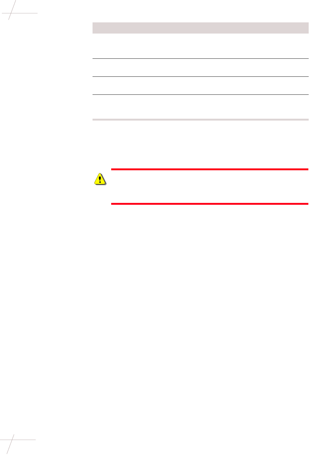
Overview A pole-mount repeater mounts on a streetlight davit at least 6 inches behind the
lamp, which allows for clearance to change the light bulb in the lamp.
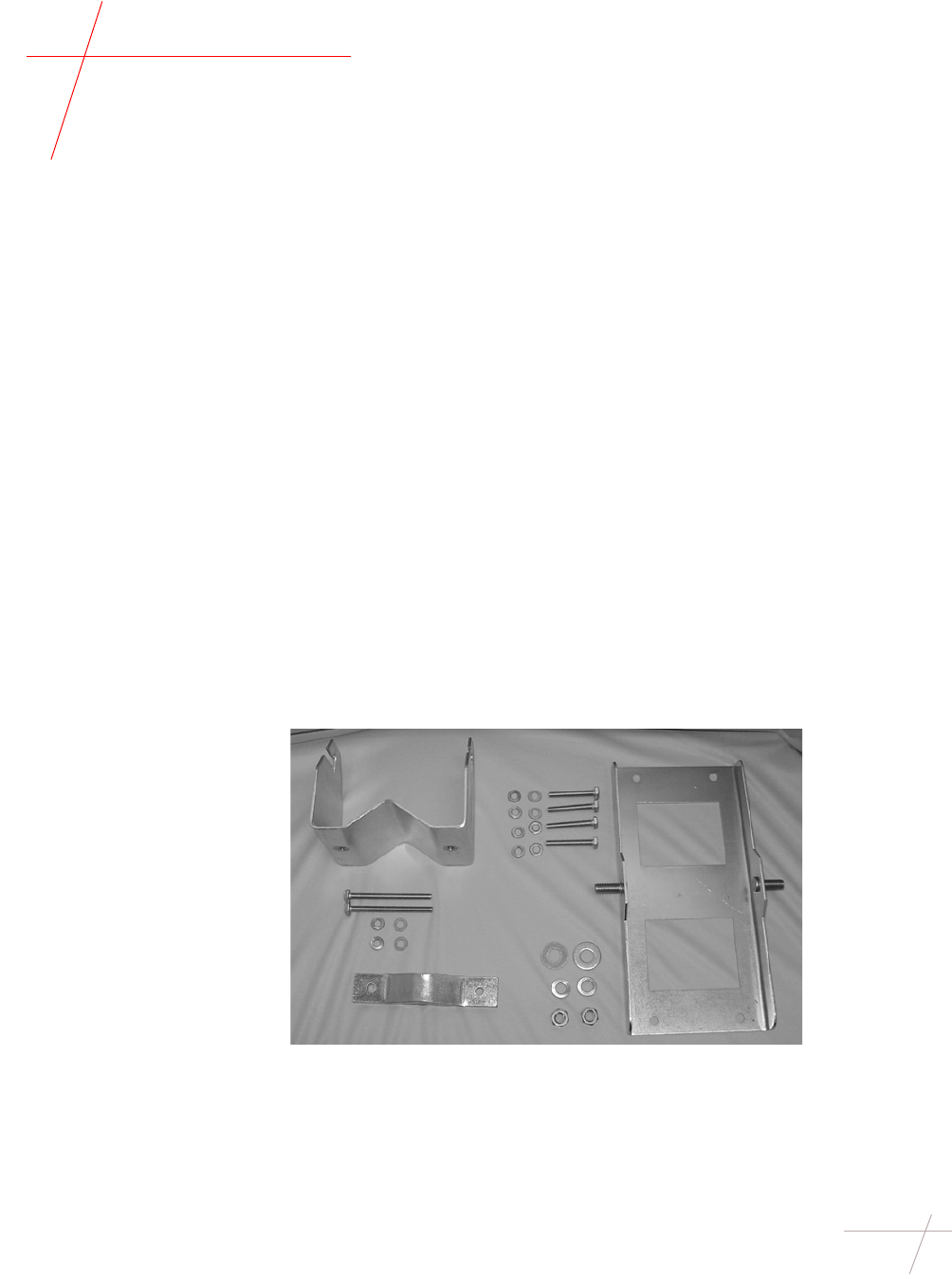
Required Hardware
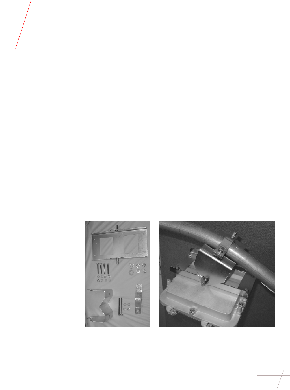
and Tools A pole-mount repeater installation requires the following tools and hardware:
• Adjustable Mounting Kit (CFG-003-002)
Adjustable Mounting Kit,
unassembled Adjustable Mounting Kit, assembled and attached
to davit and repeater

DRAFT
8 Repeater Installation Guide
TDC-0613-003b 03/06
Installing Pole-Mount Repeaters
• 7/16-inch nut driver, wrench, or ratchet-wrench
• Inch-pound torque wrench with 7/16-inch and 1/2-inch sockets
• 1/2-inch wrench
• Tie wraps (not supplied with mounting kit)
Earth Grounding Depending on the local requirements for your utility company, you may need to
ground each repeater to earth ground. If you need to earth ground a repeater,
ground the case through one of the mounting screws that attach the repeater to
the pole using a grounding cable in accordance with local utility company guide-
lines. The grounding cable is not supplied by Itron.
Wind Load Prior to installing a repeater on a light pole, ensure that the weight and estimated
project area (EPA) of the repeater does not exceed the wind load and total weight
load of the light pole. The manufacturer of the light pole should provide wind
load and weight rating specifications.
Installing a Single-
Channel Repeater
on a Davit
To install a repeater on a street light davit, follow the steps below.
Step Action
1Attach the bottom plate of the mounting kit to the top of the repeater.
For this procedure, use the following items from the Adjustable
Mounting Kit:
• (4) small lock washers
• (4) small flat washers
• (4) 1 7/8-inch long bolts
• Bottom plate
2Attach the adjustable bracket to the bottom plate. Use the following
items from the Adjustable Mounting Kit:
• (2) large lock washers
• (2) large flat washers
• (2) 1/2-inch nuts
• Adjustable bracket
• Bottom plate (attached to repeater)
IMPORTANT Do not completely tighten the nuts yet. The repeater ori-
entation will need to be adjusted once the kit is attached to the davit.
3Partially bolt one end of the top plate onto the adjustable bracket of the
mounting kit. Leave the bolt loose so that the bracket can swing. When
you are ready to install the repeater in its final position, you will swing
the bracket across the top of the davit and secure it. For this procedure,
use the following items from the Adjustable Mounting Kit:
• (1) small lock washer
• (1) flat washer
• (1) 3 1/4” bolt
4Place the antenna gasket over the antenna mount on the repeater.
DRAFT
Chapter 2 - Single-Channel Repeater Installation 9
TDC-0613-003b 03/06
Installing Pole-Mount Repeaters
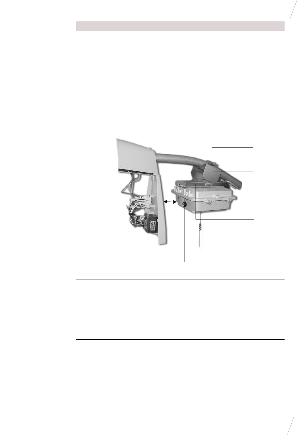
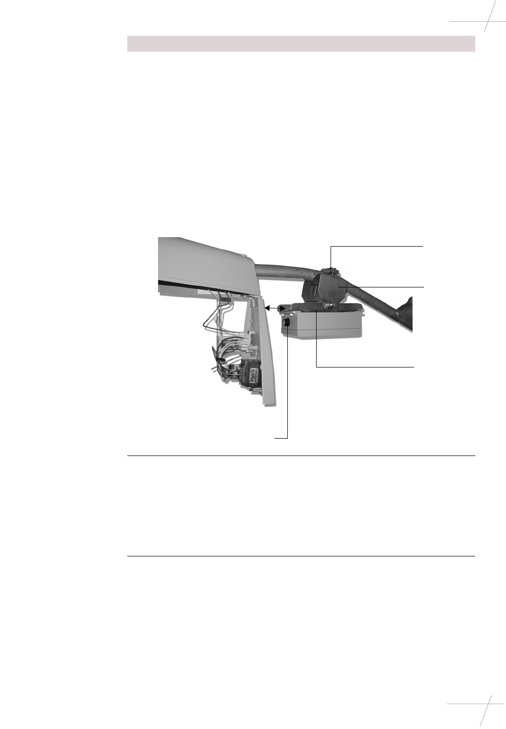
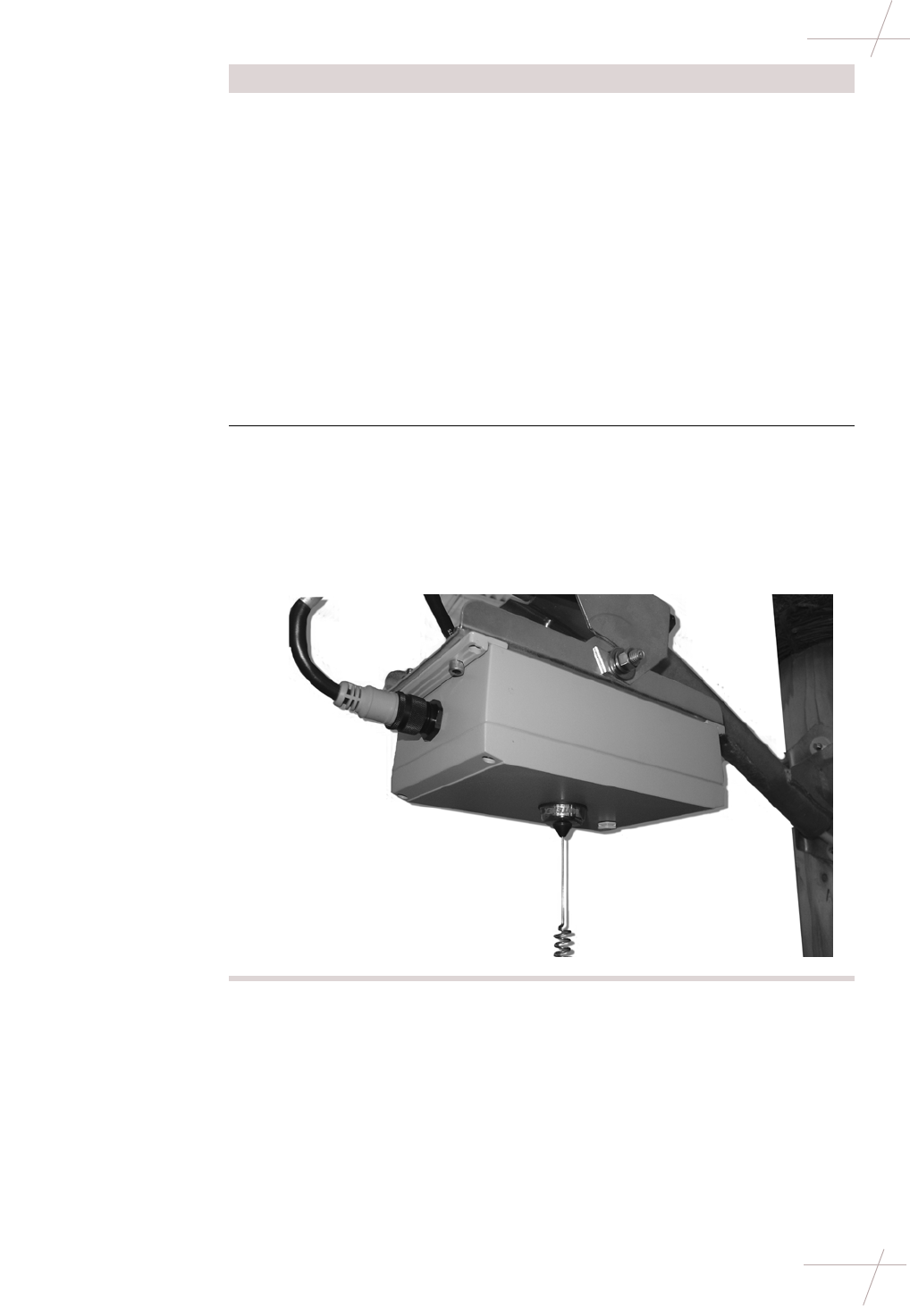
5Position the repeater beneath the davit, making sure that:
• The connectors of the repeater face the street lamp.
• The power cable can easily extend between the power connector
at the repeater and the photoelectric sensor.
• The repeater is placed is at least a 3 inches from the light fixture.
This allows the casing of the fixture to open completely, pro-
viding maintenance access when necessary.
• The bottom plate of the mounting kit is straight along the sides of
the repeater lid and is securely attached.
• The groove on the adjustable bracket of the mounting kit aligns
with the davit.
• The repeater hangs straight down.
6Swing the unsecured end of the top plate of the mounting kit over the
davit and partially bolt it in place. Then torque both bolts to 40-inch
pounds.
IMPORTANT The two hex bolts must be torqued as specified to achieve
the clamping force needed to withstand 100 MPH. wind. If the bolts are
under-torqued, the necessary clamping force may not be obtained. If
the bolts are over-torqued, the brackets may become overstressed and
clamping force may be reduced.
7Use a voltmeter to verify that the unit has power. If power is not
present, the repeater will not function. Make any corrections necessary
to provide power before continuing with the installation.
Step Action
3''
Connectors
Bottom
plate
Adjustable
bracket
Top plate
DRAFT
10 Repeater Installation Guide
TDC-0613-003b 03/06
Installing Pole-Mount Repeaters
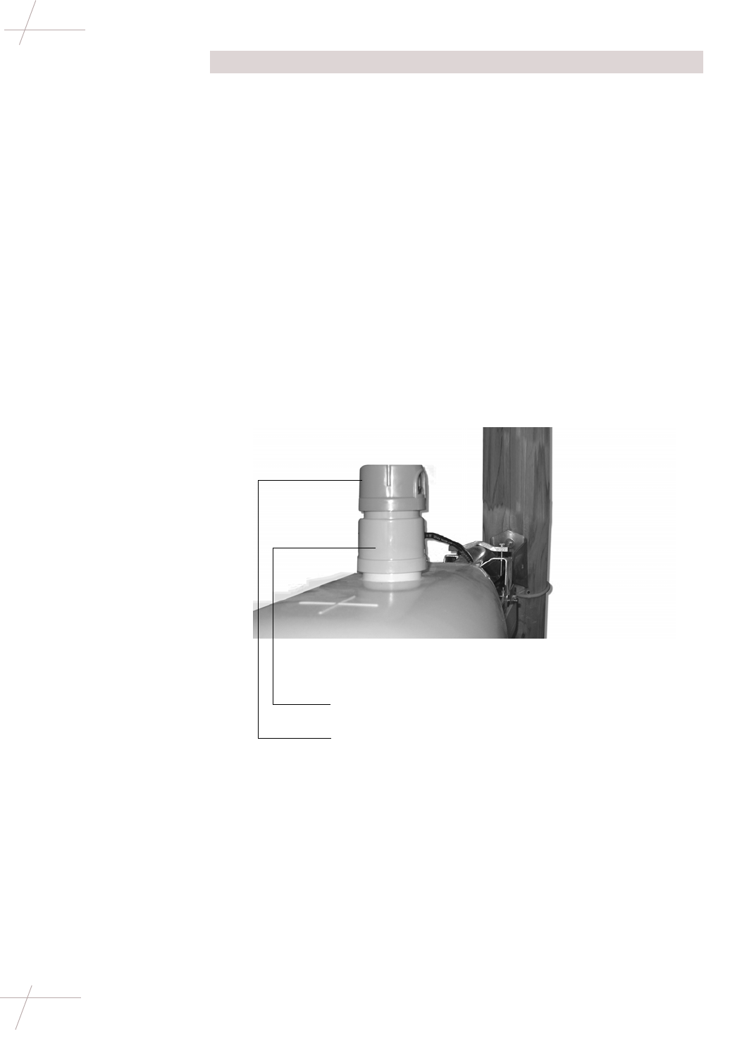
8Provide power to the repeater. This can be done by either using a pho-
toelectric sensor or hard-wiring the repeater with power.
To install the photoelectric power adapter, use the steps below.
To hard-wire power to the repeater, skip to step 9.
a. Note the current orientation of the sensor window (usually it faces
north), so that you can restore it to that orientation when you are
done.
b. Remove the photoelectric sensor.
c. Insert the repeater photoelectric power adapter into the socket and
turn to lock it in place.
d. Re-insert the photoelectric sensor into the socket on the top of the
power adapter.
e. Adjust the adapter to face the photosensor window to its original
orientation by pulling up on the adapter housing and swiveling
the housing.
f. Plug the power cord into the 5-pin connector on the repeater.
g. Use tie-wraps as necessary to secure the cable away from the
repeater housing.
Step Action
Photoelectric power adapter
Photoelectric sensor
DRAFT
Chapter 2 - Single-Channel Repeater Installation 11
TDC-0613-003b 03/06
Installing Pole-Mount Repeaters
9To power the repeater when installing it on a pole without a photo-
electric sensor, you must strip the power cable with wire strippers and
connect the individual wires to the 120V and neutral wires on the pole.
To hard-wire power to the repeater, follow the steps below.
a. Connect the unterminated end of the power cable to the power
source on the pole. The power cable is made up of two colored
wires: black and white. Connect these wires per the items below:
* Black (wire color) - Line side (signal name) - 5 (pin number)
* White (wire color) - Neutral (signal name) 1 (pin number)
b. Wrap any excess cable around the davit or use tie-wraps (not
included) to secure the cable away from the repeater.
c. Connect the other end of the power cable to the 5-pin connector on
the front of the repeater.
10 Before mounting the antenna, ensure the antenna gasket is seated
properly.
Attach the antenna. Be sure not to cross-thread the antenna when
installing it on the repeater. Attach the antenna on the bottom of the
repeater, tightening with a wrench until the antenna makes contact.
TIP To test whether the antenna makes contact, try to wiggle the
antenna. If it seems loose, continue tightening.
Step Action
DRAFT
12 Repeater Installation Guide
TDC-0613-003b 03/06
Installing Sleeve-Mount Repeaters
Installing Sleeve-Mount Repeaters
Types of Sleeve-
Mount Repeaters Sleeve-mount repeater installation depends on the type of meter socket.
Required Tools The following tools are necessary for sleeve-mount repeater installation:
• Tamper seals and associated meter installation/removal tools.
• Panduit Wave-Ty installation tool (optional). This tool cuts excess cable
and applies tension to the tension band.
Installing on a
Ringless Meter
Socket
A ringless meter socket does not use a meter seal ring between the meter and the
meter socket. Instead, the meter is secured in the meter socket by a lid. To aid
installation on a ringless meter socket, the repeater antenna does not come
attached to the repeater. Attach it to the repeater in the following procedure.
To install a repeater on a ringless meter socket, follow the steps below.
IMPORTANT The following instructions should be considered supplemental to
the meter installation and removal procedures for your utility. Follow all appli-
cable procedures and regulations when performing meter installation.
Meter Socket Type Description
Ringless A ringless mounted meter installs under the meter
box lid, which is hinged at the top of the box.
Ringed A ringed meter installs on the outside of the meter
box and is secured with a meter seal ring.
Step Action
1Remove tamper seals.
2Verify that the service is compatible with the repeater.
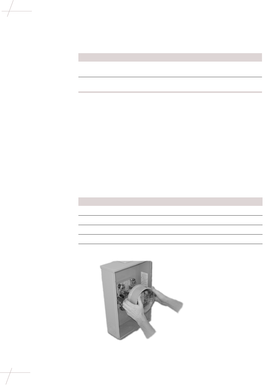
3Remove the meter socket lid.
4Remove the meter from the socket.
5Insert the repeater into the socket.
DRAFT
Chapter 2 - Single-Channel Repeater Installation 13
TDC-0613-003b 03/06
Installing Sleeve-Mount Repeaters
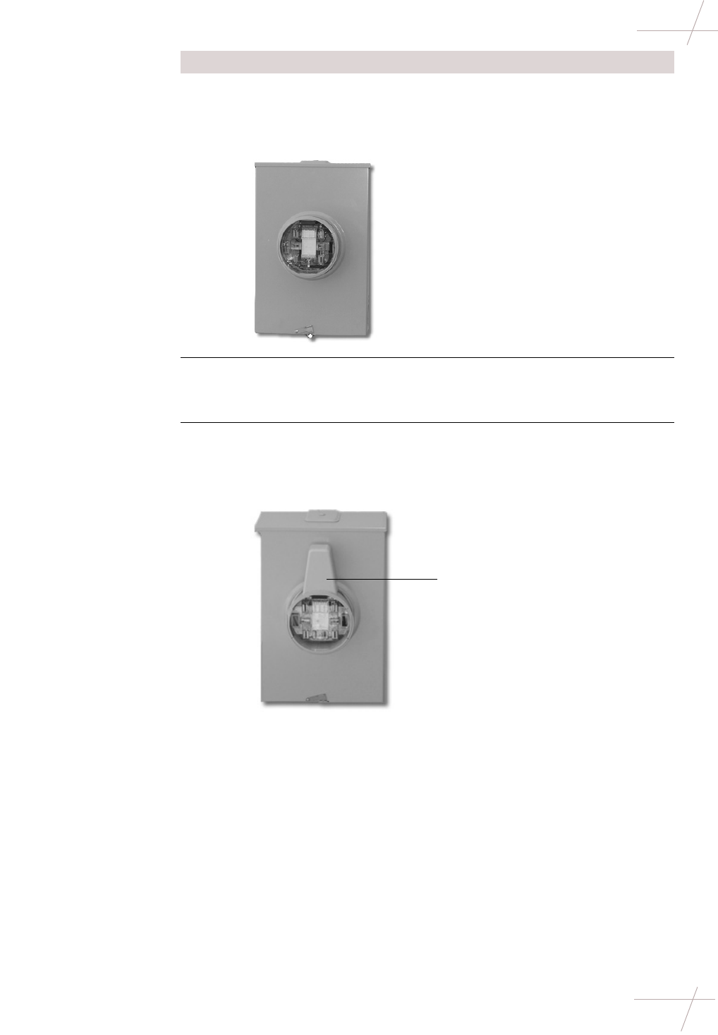
6Replace the meter socket lid.
NOTE If needed, trim the breakaway rim on the repeater sleeve using
diagonal cuts so that the socket lid will fit over the repeater.
7Remove the protective label from the double-sided tape on the bottom
of the antenna (the antenna and antenna cover are one unit).
IMPORTANT Be careful to not damage or remove the tape.
8Attach the antenna to the top of the sleeve.
IMPORTANT Ensure that it is attached forward against the shoulder and
centered on the flat area on the top of the sleeve.
Step Action
Antenna/antenna
cover attached
DRAFT
14 Repeater Installation Guide
TDC-0613-003b 03/06
Installing Sleeve-Mount Repeaters
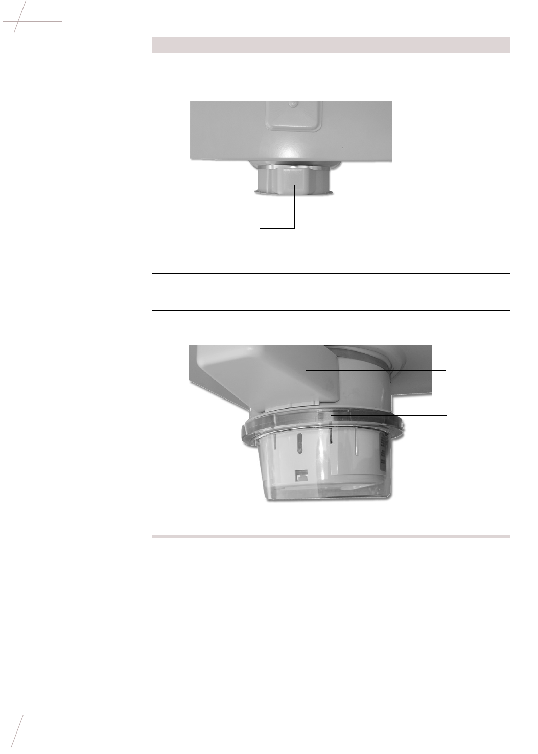
9Secure the tension band around the repeater and antenna, pulling to
tighten. Ensure that the back lip of the antenna is under the tension
band.
10 Tighten the tension band using a tension setting tool.
11 Clip off any excess material from the tension band.
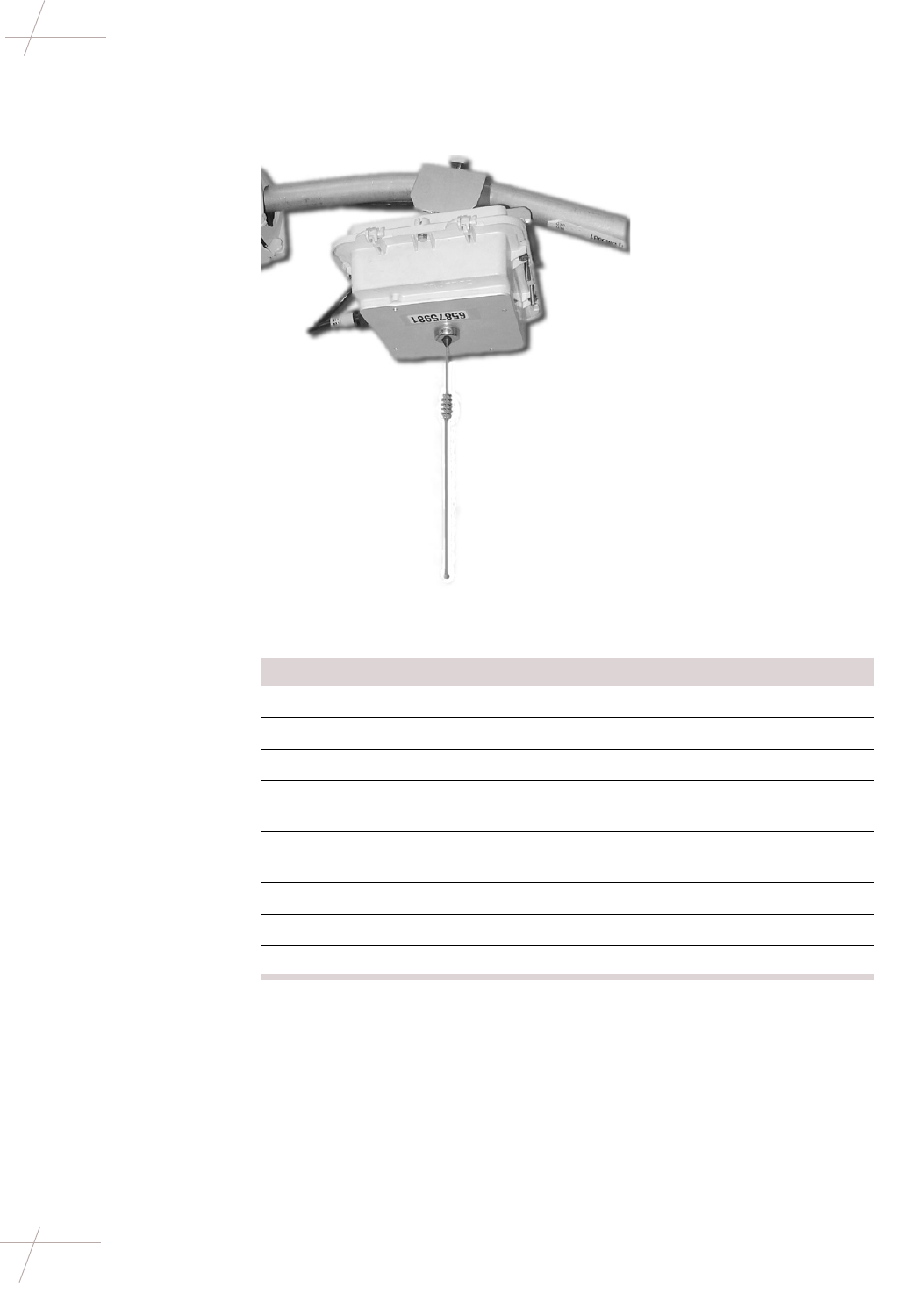
12 Snap the meter into the repeater socket.
13 Attach and tighten the meter ring, making sure to catch the antenna
cover lip under the ring band.
14 Install a tamper seal in the ring band and on the meter socket lid.
Step Action
Antenna
(top view) Tension band
Antenna
cover lip
Meter ring
DRAFT
Chapter 2 - Single-Channel Repeater Installation 15
TDC-0613-003b 03/06
Installing Sleeve-Mount Repeaters
Installing on a
Ringed Meter Socket A ringed meter socket uses a meter sealing ring to secure the meter to the socket.
To install a repeater on a ringed meter socket, do the following steps.
Step Action
1Remove tamper seals.
2Verify that the service is compatible with the repeater.
3Remove the meter seal ring.
4Pull the meter from the socket.
5Insert the repeater sleeve into the meter socket.
6Remove the protective label from the double-sided tape on the bottom
of the antenna (the antenna and antenna cover are one unit).
IMPORTANT Be careful to not damage or remove the tape.
7Attach the antenna/antenna cover unit to the top of the sleeve.
IMPORTANT Ensure that it is attached forward against the shoulder and
centered on the flat area on the top of the sleeve.
Repeater
Antenna/antenna
cover attached
DRAFT
16 Repeater Installation Guide
TDC-0613-003b 03/06
Installing Sleeve-Mount Repeaters
8Secure the tension band around the repeater and antenna, pulling to
tighten. Ensure that the back lip of the antenna is under the tension
band.
9Tighten the tension band using a tension setting tool.
10 Clip off any excess material from the tension band.
11 Secure a meter seal ring between the repeater and the meter socket.
12 Insert the meter into the repeater socket.
Step Action
Antenna
(top view) Tension band
Meter seal ring
DRAFT
Chapter 2 - Single-Channel Repeater Installation 17
TDC-0613-003b 03/06
Installing Sleeve-Mount Repeaters
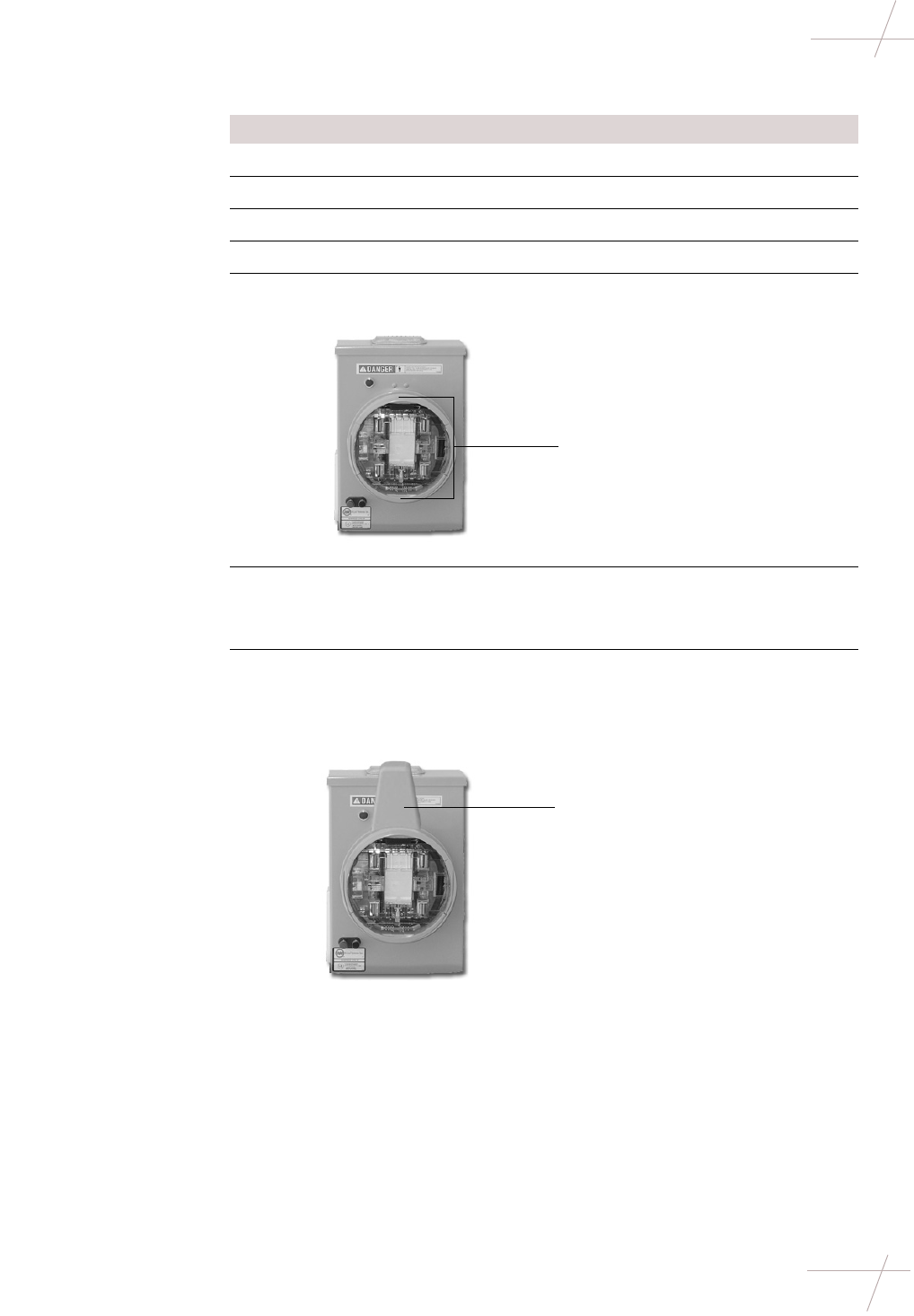
13 Attach the meter seal ring making sure to catch the antenna cover lip
under the ring band.
14 Replace the tamper seals.
Step Action
Catch cover lip
under ring

DRAFT
18 Repeater Installation Guide
TDC-0613-003b 03/06
Installing Sleeve-Mount Repeaters
DRAFT
Chapter 3 - Eight-Channel Repeater Installation 19
TDC-0613-003b 03/06
Chapter 3
Eight-Channel Repeater Installation
Getting Started
Overview This chapter shows you how to install an eight-channel repeater in the field. Your
repeater installation process will depend on the type of repeater (pole-mount or
decorative mount) and the installation location.
For more information, see:
•Installing Pole-Mount Repeaters on page 19
•Installing Decorative-Mount Repeaters on page 24
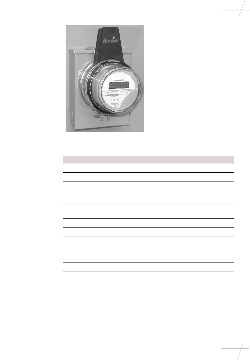
Installing Pole-Mount Repeaters
Overview A pole-mount repeater mounts on a streetlight davit at least 3 inches behind the
lamp, which allows for clearance to change the light bulb in the lamp.
Required Hardware
and Tools A pole-mount repeater installation requires the following tools and hardware:
• Adjustable Mounting Kit (CFG-003-002)
• 7/16-inch nut driver, wrench, or ratchet-wrench
• Inch-pound torque wrench with 7/16-inch and 1/2-inch sockets
Adjustable Mounting Kit, unassembled

DRAFT
20 Repeater Installation Guide
TDC-0613-003b 03/06
Installing Pole-Mount Repeaters
• 1/2-inch wrench
• Tie wraps (not supplied with mounting kit)
Earth Grounding Depending on the local requirements for your utility company, you may need to
ground each repeater to earth ground. If you need to earth ground a repeater,
ground the case through one of the mounting screws that attach the repeater to
the pole using a grounding cable in accordance with local utility company guide-
lines. The grounding cable is not supplied by Itron.
Wind Load Prior to installing a repeater on a light pole, ensure that the weight and estimated
project area (EPA) of the repeater does not exceed the wind load and total weight
load of the light pole. The manufacturer of the light pole should provide wind
load and weight rating specifications.
Installing an Eight-
Channel Repeater
on a Davit
To install an eight-channel repeater on a street light davit, follow the steps below.
Step Action
1Attach the bottom plate of the mounting kit to the top of the repeater.
For this procedure, use the following items from the Adjustable
Mounting Kit:
• (4) small lock washers
• (4) small flat washers
• (4) 1 7/8-inch long bolts
• Bottom plate
2Attach the adjustable bracket to the bottom plate. Use the following
items from the Adjustable Mounting Kit:
• (2) large lock washers
• (2) large flat washers
• (2) 1/2-inch nuts
• Adjustable bracket
• Bottom plate (attached to repeater)
IMPORTANT Do not completely tighten the nuts yet. The repeater ori-
entation will need to be adjusted once the kit is attached to the davit.
3Partially bolt one end of the top plate onto the adjustable bracket of the
mounting kit. Leave the bolt loose so that the bracket can swing. When
you are ready to install the repeater in its final position, you will swing
the bracket across the top of the davit and secure it. For this procedure,
use the following items from the Adjustable Mounting Kit:
• (1) small lock washer
• (1) flat washer
• (1) 3 1/4” bolt
4Place the antenna gasket over the antenna mount on the repeater.
DRAFT
Chapter 3 - Eight-Channel Repeater Installation 21
TDC-0613-003b 03/06
Installing Pole-Mount Repeaters
5Position the repeater beneath the davit, making sure that:
• The connectors of the repeater face the street lamp.
• The power cable can easily extend between the power connector
at the repeater and the photoelectric sensor.
• The repeater is placed is at least a 3 inches from the light fixture.
This allows the casing of the fixture to open completely, pro-
viding maintenance access when necessary.
• The bottom plate of the mounting kit is straight along the sides of
the repeater lid and is securely attached.
• The groove on the adjustable bracket of the mounting kit aligns
with the davit.
• The repeater hangs straight down.
6Swing the unsecured end of the top plate of the mounting kit over the
davit and partially bolt it in place. Then torque both bolts to 40 inch-
pounds.
IMPORTANT The two hex bolts must be torqued as specified to achieve
the clamping force needed to withstand 100 MPH. wind. If the bolts are
under-torqued, the necessary clamping force may not be obtained. If
the bolts are over-torqued, the brackets may become overstressed and
clamping force may be reduced.
7Use a voltmeter to verify that the unit has power. If power is not
present, the repeater will not function. Make any corrections necessary
to provide power before continuing with the installation.
Step Action
3''
Connectors
Bottom
plate
Adjustable
bracket
Top plate
DRAFT
22 Repeater Installation Guide
TDC-0613-003b 03/06
Installing Pole-Mount Repeaters
8Provide power to the repeater. This can be done by either using a pho-
toelectric sensor or hard-wiring the repeater with power.
To install the photoelectric power adapter, use the steps below.
To hard-wire power to the repeater, skip to step 9.
a. Note the current orientation of the sensor window (usually it faces
north), so that you can restore it to that orientation when you are
done.
b. Remove the photoelectric sensor.
c. Insert the repeater photoelectric power adapter into the socket and
turn to lock it in place.
d. Re-insert the photoelectric sensor into the socket on the top of the
power adapter.
e. Adjust the adapter to face the photosensor window to its original
orientation by pulling up on the adapter housing and swiveling
the housing.
f. Plug the power cord into the 5-pin connector on the repeater.
g. Use tie-wraps as necessary to secure the cable away from the
repeater housing.
Step Action
Photoelectric power adapter
Photoelectric sensor
DRAFT
Chapter 3 - Eight-Channel Repeater Installation 23
TDC-0613-003b 03/06
Installing Pole-Mount Repeaters
9To power the repeater when installing it on a pole without a photo-
electric sensor, you must strip the power cable with wire strippers and
connect the individual wires to the 120V and neutral wires on the pole.
To hard-wire power to the repeater, follow the steps below.
a. Connect the unterminated end of the power cable to the power
source on the pole. The power cable is made up of two colored
wires: black and white. Connect these wires per the items below:
* Black (wire color) - Line side (signal name) - 5 (pin number)
* White (wire color) - Neutral (signal name) 1 (pin number)
b. Wrap any excess cable around the davit or use tie-wraps (not
included) to secure the cable away from the repeater.
c. Connect the other end of the power cable to the 5-pin connector on
the front of the repeater.
10 Before mounting the antenna, ensure the antenna gasket is seated
properly.
Attach the antenna. Be sure not to cross-thread the antenna when
installing it on the repeater. Attach the antenna on the bottom of the
repeater, tightening with a wrench until the antenna makes contact.
TIP To test whether the antenna makes contact, try to wiggle the
antenna. If it seems loose, continue tightening.
Step Action
DRAFT
24 Repeater Installation Guide
TDC-0613-003b 03/06
Installing Decorative-Mount Repeaters
Installing Decorative-Mount Repeaters
Overview Decorative-mount repeaters are designed to “blend in” more with their sur-
roundings. These repeaters are typically installed in developments, residential
areas, or other areas where an emphasis is placed on the appearance of the
device.
Installing a
Decorative-Mount
Repeater
Installing a decorative-mount repeater is a relatively simply process. To install
this type of repeater, follow the steps below.
Step Action
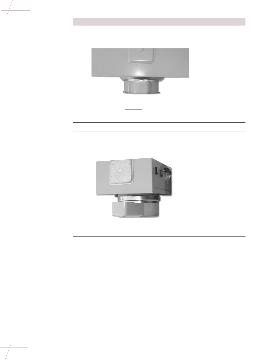
1Remove the existing photo-electric sensor from the decorative
lamppost. Be sure to note the orientation of sensor window (this typi-
cally faces north).
NOTE The existing sensor is no longer needed. The decorative repeater
has a built-in photo-electric sensor.
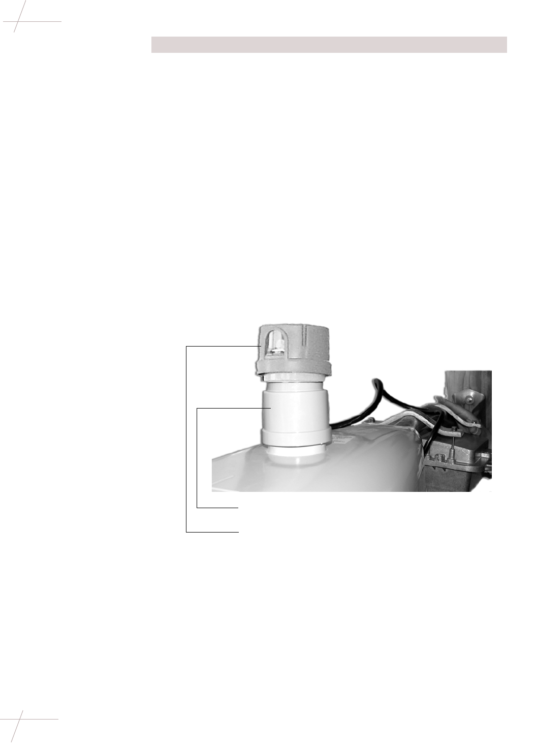
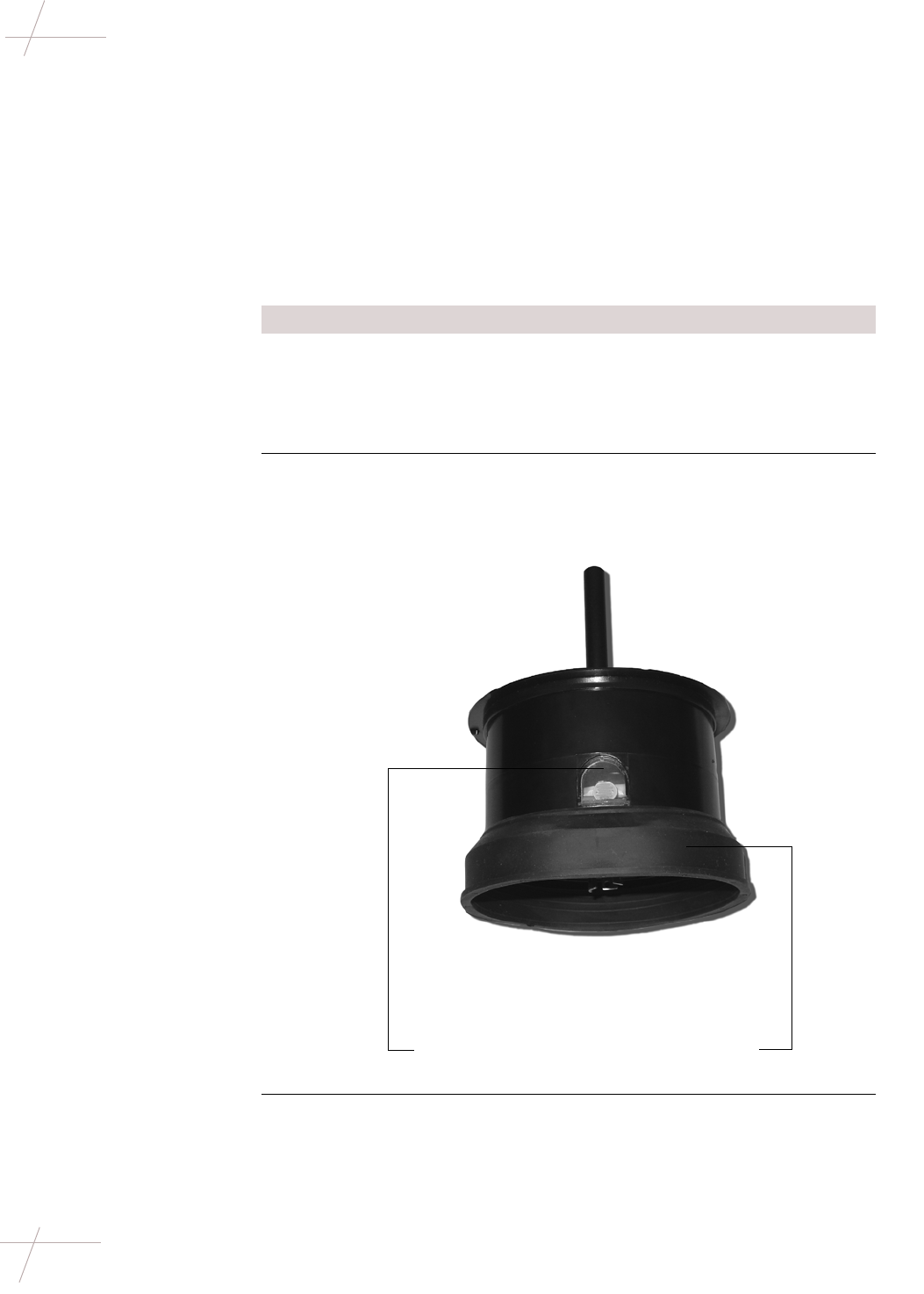
2Slide the rubber seal over the base of the repeater, as shown below. The
seal should lay just below the photo-electric sensor window on the
repeater.
3If necessary, rotate the socket so that the photo-electric sensor window
will be oriented properly (typically facing north) when the repeater is
installed. If a photo-electric sensor was previously installed, the socket
should already be oriented properly.
Photo-electric
sensor window Rubber seal

DRAFT
Chapter 3 - Eight-Channel Repeater Installation 25
TDC-0613-003b 03/06
Installing Decorative-Mount Repeaters
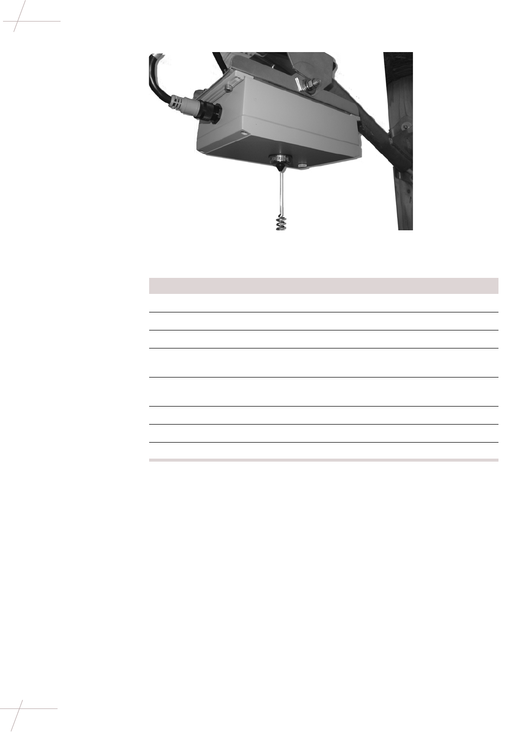
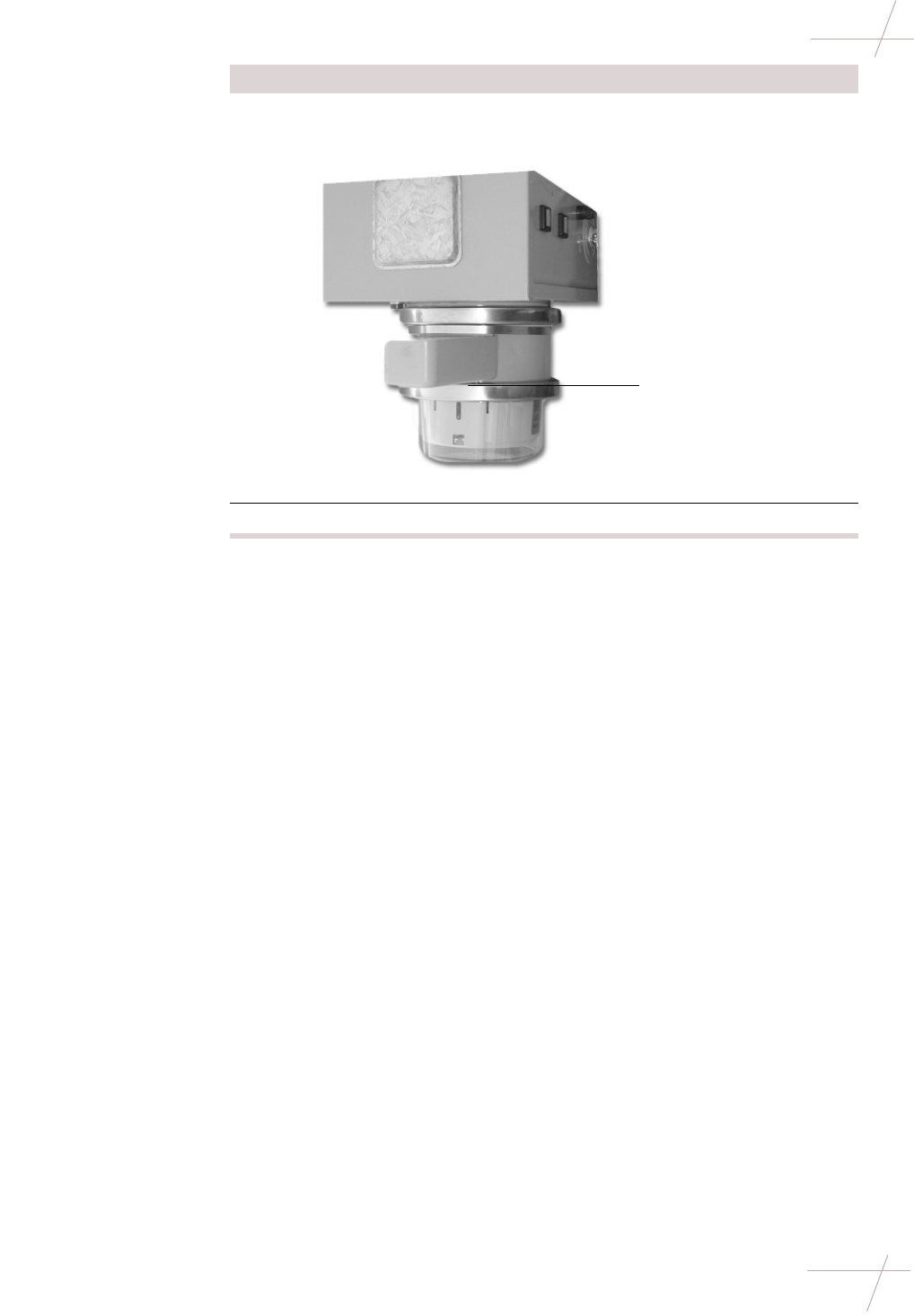
4Attach the repeater to the top of the lamppost. Be sure to align the
prongs on the repeater with the corresponding sockets on the lamppost.
5Slide the rubber seal down to the top of the lamppost.
Verify that a tight seal around the entire repeater has been created; this
will keep water from intruding into the repeater and top of the
lamppost.
Step Action

DRAFT
26 Repeater Installation Guide
TDC-0613-003b 03/06
Installing Decorative-Mount Repeaters
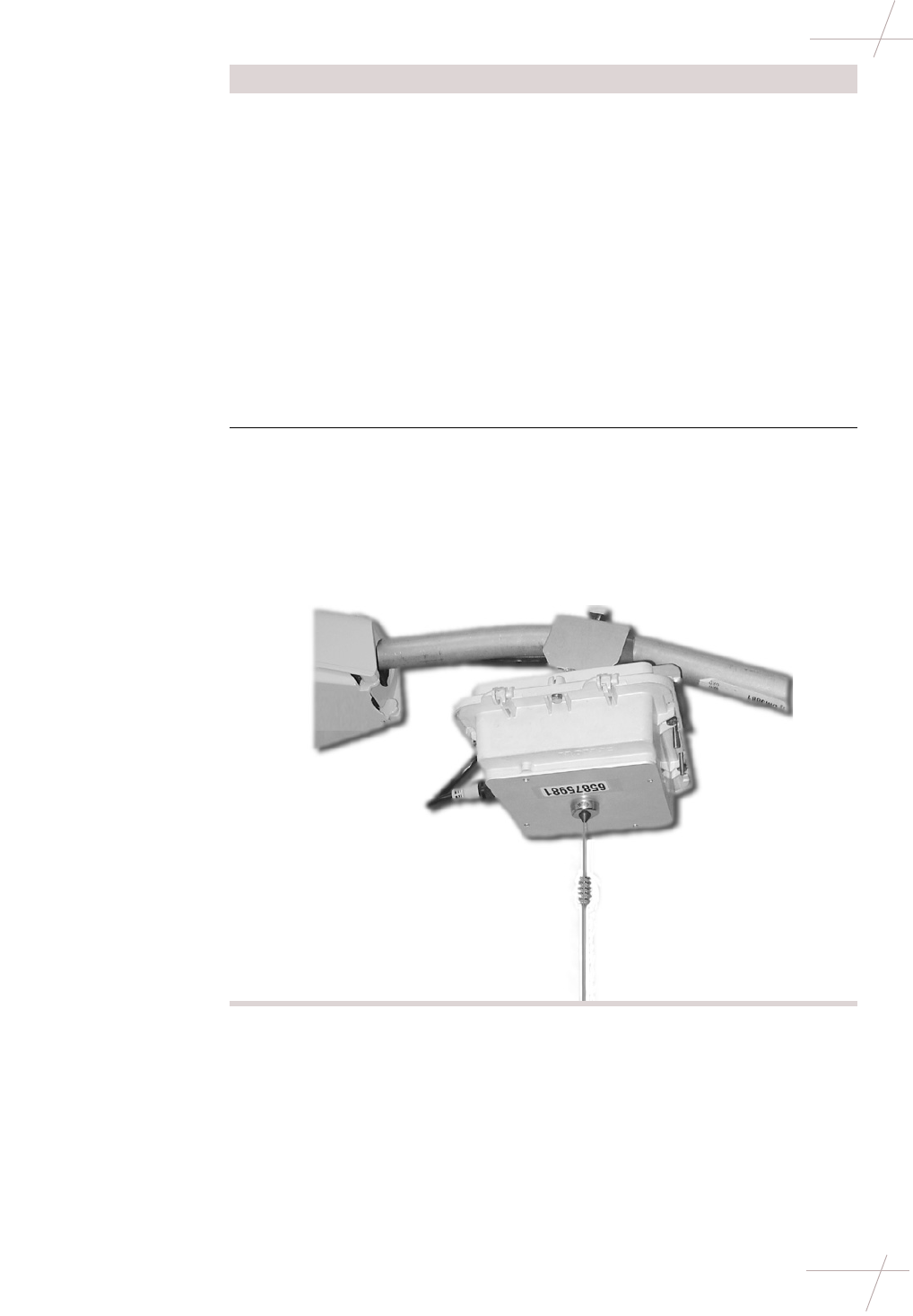
6When you have finished, your lamppost should look similar to the
example below.
Step Action