Itron GPRSCOL50 Cellular/ PCS GSM/ GPRS Power Meter with Frequency Hopping Transmitter User Manual
Itron Cellular/ PCS GSM/ GPRS Power Meter with Frequency Hopping Transmitter Users Manual
Itron >
Users Manual

© 2008 SmartSynch™
SmartMeter™ System
Elster A3 ALPHA® Meter/Collector 5.0
GPRS SmartMeter
User Guide

A3 Collector GPRS 5.0 SmartMeter User Guide
A3 GPRS Collector 5.0 2
Copyrights
Copyright 2008 SmartSynch®, Inc. All rights reserved.
No part of this documentation may be reproduced transmitted, processed, or recorded by any means or
form, or be released to any third party without the express written consent of SmartSynch, Inc.
Trademarks
SmartSynch®, SmartSynch logo, TMS™, and SmartMeter™ are trademarks or registered trademarks of
SmartSynch, Inc. All other companies, brands, and product names listed herein are trademarks or
registered trademarks of their respective holders.
Document Revisions
Each revision of this document is designated with a letter, beginning with “A”. SmartSynch, Inc. reserves
the right to revise this publication and to make any modifications to its content, at any time, without
obligation to notify any party, person, or entity of such revisions or changes. Occasionally, changes or
variations exist in the products that are not reflected in the documentation. Generally, if such changes or
variations are known to exist and affect the product significantly, release notes will accompany the
documentation.
The information in this guide should not be considered as all-inclusive or covering all cases for events
that may occur. If further information is required, consult your technical support representative.
See the License Agreement contained in the product for complete license information.
Contact your technical support representative for more information on any of our products.

A3 GPRS Collector 5.0 SmartMeter User Guide
A3 GPRS Collector 5.0 3
Table of Contents
1 INTRODUCTION ...............................................................................................................................................5
1.1 ABOUT THIS GUIDE........................................................................................................................................5
1.2 REFERENCE MATERIALS.................................................................................................................................5
1.3 CONTACTING SMARTSYNCH...........................................................................................................................5
1.3.1 Technical Support..................................................................................................................................5
1.3.2 Documentation Feedback ......................................................................................................................6
1.3.3 SmartSynch Headquarters.....................................................................................................................6
2 GETTING STARTED.........................................................................................................................................7
2.1 OPERATIONS...................................................................................................................................................7
2.2 SAFETY PRECAUTIONS....................................................................................................................................7
2.2.1 Interference with Medical Equipment....................................................................................................7
2.2.2 Fire or Explosion Hazards ....................................................................................................................7
2.2.3 Interference with Other Devices............................................................................................................8
2.3 PREREQUISITES...............................................................................................................................................8
3 INSTALLING THE A3 ALPHA® COLLECTOR SMARTMETER .............................................................9
3.1 PRELIMINARY INSPECTIONS............................................................................................................................9
3.2 INSTALLATION PROCESS.................................................................................................................................9
3.2.1 Option 1: Direct Field Installation........................................................................................................9
3.2.2 Option 2: Meter Shop Test and Field Installation .................................................................................9
3.2.3 Meter Installation ..................................................................................................................................9
3.3 COMMUNICATING WITH THE SMARTMETER USING MAS .............................................................................10
4 TROUBLESHOOTING....................................................................................................................................11
4.1 TROUBLESHOOTING PROCESS FLOW ............................................................................................................11
4.2 TROUBLESHOOTING PROCESS DESCRIPTION.................................................................................................12
5 REQUIREMENTS AND COMPLIANCE......................................................................................................14
5.1 FCC GRANT STATEMENT .............................................................................................................................14
5.2 COMPLIANCE STATEMENT (PART 15.19)......................................................................................................15
5.3 WARNING (PART 15.21) ...............................................................................................................................15
5.4 RF RADIATION SAFETY GUIDELINES PER PART 2 OF FCC RULES AND REGULATIONS .................................15
5.5 USER INFORMATION (PART 15.105) .............................................................................................................15
5.6 INDUSTRY CANADA STATEMENT..................................................................................................................15

A3 GPRS Collector 5.0 SmartMeter User Guide
A3 GPRS Collector 5.0 5
1 Introduction
1.1 About This Guide
This document is a manual designed to help guide you through the testing, installation and activation of
your A3 ALPHA® Collector SmartMeter. This manual provides general instructions on the support of your
SmartMeter and references to supporting manufacturer documentation for detailed guidelines and
instructions on features and operating characteristics of the SmartMeter for installation, programming,
communication, and troubleshooting.
1.2 Reference Materials
The following reference software and documentation are pertinent to the successful installation and use
of the A3 ALPHA® Collector SmartMeter.
Elster
• A3 ALPHA® Collector Device Manual
• Metercat Software
• Metercat Installation Guide
• Metercat User Guide
SmartSynch
For more information on the A3 ALPHA® Collector SmartMeter, see the product brochure and spec sheet,
available online at TBD.
1.3 Contacting SmartSynch
1.3.1 Technical Support
SmartSynch’s technical support staff is ready to answer your technical questions. Your technical support
representative can provide information about the latest SmartSynch products, upgrade options, and more.
Contact your technical support representative directly, through the Online Customer Support Center at
http://smartsynch.com/support/login.html, or by email at cs@smartsynch.com.
Note: You must be a registered user to access SmartSynch’s online support services.
Help us help you
When contacting technical support please provide the following information for the fastest possible
service:
• Your name, company name, and contact number
• SmartMeter make and model (meter manufacturer, SSI version number)
• Complete description of the issue, including the steps to reproduce it
• Wording of any message(s) displayed when the issue was encountered
• Action taken to resolve the problem

A3 GPRS Collector 5.0 SmartMeter User Guide
A3 GPRS Collector 5.0 6
1.3.2 Documentation Feedback
SmartSynch, Inc. strives to produce quality documentation for our products and welcomes your feedback.
If you have comments or recommendations about our online help or printed guides, you can email us.
Please send email messages to cs@smartsynch.com. This email address is only for documentation
feedback. If you have a technical question, please contact your technical support representative.
1.3.3 SmartSynch Headquarters
SmartSynch, an energy technology company based in Jackson, Mississippi, is the leading provider of
advanced metering solutions to the energy and utility industry. Its core product, the SmartMeter System,
enables energy and utility companies to communicate with commercial and industrial electricity meters
using wireless communications and the Internet. The SmartMeter System manages the delivery of critical
information to any application system, workstation, computer, or browser-enabled personal
communication device.
Mailing Address: SmartSynch, Inc. Telephone: 601-362-1780
P.O. Box 12250
Jackson, MS 39236-2250 Fax: 601-362-1787
Street Address: 4400 Old Canton Road World Wide Web: www.smartsynch.com
Suite 300
Jackson, MS 39211 Office Hours: 8:00 a.m. to 5:00 p.m.
Central Time
A3 GPRS Collector 5.0 SmartMeter User Guide
A3 GPRS Collector 5.0 7
2 Getting Started
Please review the reference documentation before you begin the installation and use of the supporting
software.
2.1 Operations
The A3 ALPHA® Collector SmartMeter is an Elster A3 ALPHA® Collector electronic single-phase
electricity meter integrated with a SmartSynch Interface (SSI) Module, which fully supports ANSI
standards for electricity metering and is intended for use by commercial and industrial utility customers.
The A3 ALPHA® Collector SmartMeter offers you secure over-the-air transfer of data between the
SmartMeter and Elster’s Metering Automation Server (MAS).
2.2 Safety Precautions
The A3 ALPHA® Collector SmartMeter contains a Motorola G24 GPRS Cellular Engine for wireless
communication purposes. The following safety precautions pertain to the hazards related to this device’s
radio frequency (RF) functionality and must be observed during all phases of installation, operation,
service, and repair. Failure to comply with these precautions violates safety standards of design,
manufacture, and intended use of the product.
WARNING!
Use authorized utility procedures for installing, maintaining, and removing a SmartMeter.
Equipment damage, personal injury, or death can result if devices are not properly
installed and operated.
2.2.1 Interference with Medical Equipment
Before installing the A3 ALPHA® Collector SmartMeter on the premises of a hospital or other health care
facility, observe the restrictions on the use of mobile communication devices in sensitive areas. Some
medical equipment may be sensitive to radio frequency (RF) energy, possibly requiring the meter to be
properly shielded or placed in an alternate location.
The operation of cardiac pacemakers, hearing aids, and other implanted medical equipment can be
affected by interference from cellular devices placed too closely. Pacemaker patients are advised to
observe the same precautions recommended for handheld mobile phones while installing or operating the
A3 ALPHA® Collector SmartMeter.
2.2.2 Fire or Explosion Hazards
Do not install or operate the A3 ALPHA® Collector SmartMeter in the presence of flammable gases or
fumes. This includes gasoline stations, fuel depots, chemical plants, or sites where blasting operations
are in progress. Operation of any electrical equipment in potentially explosive atmospheres can constitute
a safety hazard.

A3 GPRS Collector 5.0 SmartMeter User Guide
A3 GPRS Collector 5.0 8
2.2.3 Interference with Other Devices
The communication module embedded in the A3 ALPHA® Collector SmartMeter receives and transmits
radio frequency (RF) energy while in operation. Interference can occur if it is placed too close to
televisions, radios, computers, or inadequately sheltered equipment. Follow any applicable regulations if
you suspect that this device may cause interference or danger.
2.3 Prerequisites
To perform the installation of your SmartMeter, you must have access to the following supporting software
and should have reviewed relevant documentation:
Elster meter programming software, for programming the A3 ALPHA® Collector. Metercat
communicates with the A3 ALPHA® Collector for program development, meter programming, meter
reading, meter testing, and report generation. Metercat system requirements and installation instructions
may be obtained in the:
• Metercat Installation Guide
• Metercat User Guide

A3 GPRS Collector 5.0 SmartMeter User Guide
A3 GPRS Collector 5.0 9
3 Installing the A3 ALPHA® Collector 5.0 SmartMeter
3.1 Preliminary Inspections
The A3 ALPHA® Collector SmartMeter is calibrated and tested at the factory and is ready for installation.
Before installing and applying power to the SmartMeter, a quick inspection of the SmartMeter is
recommended to ensure there is no damage to the SmartMeter, which could possibly occur during
shipping. Physical damage to the SmartMeter indicates potential damage to the inside of the SmartMeter.
Do not connect power to a SmartMeter that is suspected of having internal damage. Contact your
SmartSynch technical support representative if you suspect your SmartMeter is damaged.
3.2 Installation Process
The customer will receive meters in a “Preconfigured” state. This means that meters have been
integrated with an SSI SmartMeter Module loaded with the SSI embedded software, an inactive (unless
shipped active per customer request) cellular network Subscriber Identity Module (SIM) card, and has
passed several quality control stages. In addition, a Ship file containing device specific information has
been generated by SmartSynch for the customer. This file is imported into a configuration server by SSI
personnel and a copy is provided to the customer. Upon SIM card activation, upon shipment, or later
upon customer request, an Activation file containing cellular network-specific information is generated.
This file is also imported into the configuration server and a copy is provided to the customer.
Typically, a customer can deploy the meter using one of two methods, depending
on business needs:
3.2.1 Option 1: Direct Field Installation
This option is used when the customer prefers immediate deployment of the meters “from the box to the
base.” This option is desirable in a deployment situation where a large number of meters need to be
deployed in a relatively short period of time. The customer-specific information is automatically Over-the-
Air downloaded to the SSI module upon energizing the meter and no addition action is needed on-site.
Follow the meter installation instructions in Section 3.2.3.
3.2.2 Option 2: Meter Shop Test and Field Installation
There is no need for the Meter Shop to reprogram and test the SmartMeter when it arrives. Upon
shipment, the meter will have undergone significant functional and RF testing at the factory. Internal
quality control checks will ensure the SSI module is able to communicate with the meter successfully as
well as communicate with all other internal components before it is shipped. The device will also arrive in
a generic “Preconfigured” state with no customer-specific data stored in internal memory. There is no
need for the Meter Shop to perform any programming steps on the meter.
3.2.3 Meter Installation
1. The installer verifies network coverage with a SmartSynch Coverage Validation Unit (CVU).
Note: If the option board display codes are enabled in the meter program, the Received
Signal Strength Indicator (RSSI) display values can be used to verify coverage
without the CVU. Refer to section 5 for additional information.
2. The meter is placed in the socket and energized. The meter is now in the Pre-Configured state.

A3 GPRS Collector 5.0 SmartMeter User Guide
A3 GPRS Collector 5.0 10
3. Once in the Pre-Configured state, the SSI embedded software transmits an Auto-Configuration
message to the configuration server.
4. Upon receiving the meter’s Auto-Configuration message, the configuration server will set all of the
customer specific parameters into the SSI module’s non-volatile memory.
5. When the SSI module inside the meter is fully configured with the customer specific information it
will immediately send an Auto-Registration message to the configuration server.
6. Once the meter is registered to the configuration server, meter data can be collected from the
meter via MAS.
3.3 Communicating with the SmartMeter using MAS
MAS must be programmed with the IP address of the SmartSynch Routing Solution (SRS) and the port
associated with the meter to be communicated with.
Once a message is sent from MAS, the SRS routes the message to the appropriate meter in the form of
an SMS. Once the meter receives the SMS, the meter opens a socket with the SRS. The SRS then joins
the socket to the meter with the socket to MAS allowing messages to flow freely between the two.
A3 GPRS Collector 5.0 SmartMeter User Guide
A3 GPRS Collector 5.0 11
4 Troubleshooting
4.1 Troubleshooting Process Flow
The troubleshooting support directives may involve a number of participants to resolve the issue,
depending on the type of issue involved. Resolution may include TMS Administrators, TMS Operators,
Field Meter Support personnel, or any user who may be required to support the TMS, its clients, or
related data.
Section 4.2 describes the required corrective action that corresponds with each step in the flowcharts.
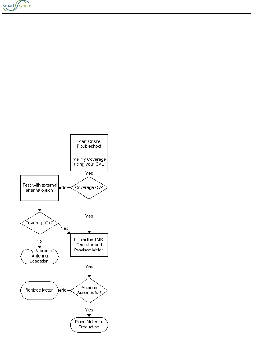
The first chart describes the process for Onsite (Field) troubleshooting, and the next describes the
process from the TMS Operator’s perspective
Onsite Troubleshooting Flowchart
A3 GPRS Collector 5.0 SmartMeter User Guide
A3 GPRS Collector 5.0 12
With either process, be sure to perform these initial steps:
1. Confirm that the meter is actually installed in the field.
2. Verify that the PIN for that meter is correct.
3. Verify that the site exceeds the acceptable minimums using the Coverage Validation Unit.
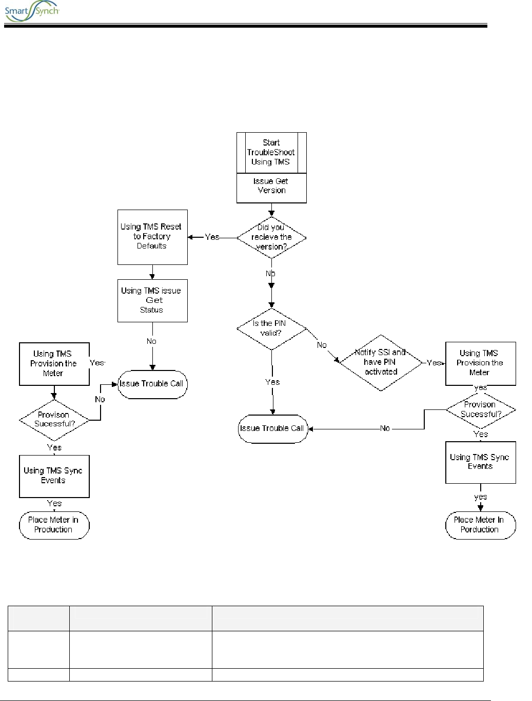
TMS Troubleshooting Flowchart (for meters that have been previously provisioned successfully)
4.2 Troubleshooting Process Description
Process
Steps Description Action
1 Is Meter Installed in field? Check work orders, inventory management, or verify with
Field Personnel that meter is installed and energized at a
valid Customer location.
2 Install Meter Refer to the Installation section of this document

A3 GPRS Collector 5.0 SmartMeter User Guide
A3 GPRS Collector 5.0 13
Process
Steps Description Action
3 Is Pin # Correct? Validate that the pin number in the TMS system is
indeed the pin number that is matched with the correct
meter. Checking the manufacturer’s spreadsheet sent
with the meters and/or visually inspecting the label on
the meter can accomplish this task.
4 Did site pass CVU tests?
Check Meter Test Person’s site validation notes and
verify that test were properly run and meet the minimum
requirements.
5 Get Version? Perform Get Version ANSI action on device. (See TMS
User Guide)
6 Restore Meter to Factory
Defaults?
Perform Restore Meter to Factory Defaults ANSI (see
TMS User Guide)
7 Get Status? Perform Get Status ANSI action on device. (See TMS
User Guide)
8 Get Status Successful? Check the results of the Get Status ANSI using Event
Search and View Details. (See TMS User Guide)
9 Execute the following Task:
Provision
Execute Provision on the meter. (See TMS User Guide)
10 Did the meter provision?
Check the results of the Provision ANSI using Event
Search and View Details. (See TMS User Guide)
11 Sync System to Device
If meter is already in a Functional Group, user will need
to execute task Sync System to device. (See TMS User
Guide)
12 Put meter into production
system
Do the necessary paperwork to put meter on production
system and notify appropriate stakeholders.
13 Ping the Module Using the
Internet/Web Browser Go to the Network web page. Send a message tab.
Enter in the pin number of the device and a
miscellaneous message in the message field. Click
Send. (See Section 4.2.1)
14 Is Pin Active?
After using the internet/web browser, does the screen
say message submitted (yes) or invalid pin (no)? (See
Section 4.2.1)
15 Activate Pin Through
SmartSynch Log on to the OCS and create a new case for the invalid
pin. SmartSynch Personnel will take care of the issue
and notify the user when the PIN is active.
16 Field Site Visit - Call into
TMS Operator Dispatch a meter tech to perform the Onsite
troubleshooting procedure and have them call into the
TMS operator at the time of completion.
17 Bring Meter in for evaluation
Replace meter with another SmartMeter and bring into
Meter Shop for further evaluation.
A3 GPRS Collector 5.0 SmartMeter User Guide
A3 GPRS Collector 5.0 14
5 Requirements and Compliance
The A3 GPRS Collector 5.0 SmartMeter is compliant with all applicable Federal Communications
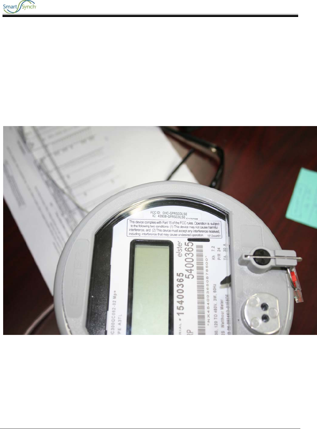
Commission (FCC) and Industry Canada (IC) requirements. The FCC and IC identification numbers for
the A3 ALPHA® Collector GPRS SmartMeter are listed as follows:
FCC identifier: QHC-GPRSCOL50
IC identifier: 4393B-GPRSCOL50
This certification is granted to SmartSynch Inc.
A3 GPRS Collector 5.0 FCC Label
5.1 FCC Grant Statement
The antennas used for this transmitter must be installed to provide a minimum separation
distance of 20 cm from all persons, and must not be co-located or operate in conjunction
with any other antenna or transmitter.

A3 GPRS Collector 5.0 SmartMeter User Guide
A3 GPRS Collector 5.0 15
5.2 Compliance Statement (Part 15.19)
The A3 ALPHA meter/collector complies with Part 15 of the FCC Rules and with RSS-210 of Industry
Canada. Operation is subject to the following two conditions:
1. This device may not cause harmful interference, and
2. This device must accept any interference received, including interference that may cause
undesired operation.
5.3 Warning (Part 15.21)
Changes or modifications not expressly approved by Elster Electricity, LLC and SmartSynch, Inc. could
void the user’s authority to operate the equipment.
5.4 RF Radiation Safety Guidelines per Part 2 of FCC Rules and
Regulations
The meter should be installed in a location where there will be a separation greater than 20 cm (8 inches)
from locations occupied by humans.
5.5 User Information (Part 15.105)
The A3 ALPHA meter/collector has been tested and found to comply with the limits for a Class B digital
device, pursuant to part 15 of the FCC Rules. These limits are designed to provide reasonable protection
against harmful interference in a residential installation. This equipment generates, uses and can radiate
radio frequency energy and, if not installed and used in accordance with the instructions, may cause
harmful interference to radio communications. However, there is no guarantee that interference will not
occur in a particular installation. If this equipment does cause harmful interference to radio or television
reception, the user is encouraged to try to correct the interference by one or more of the following
measures:
• Reorient or relocate the receiving antenna.
• Move the receiving equipment farther away from the A3 ALPHA meter/collector.
• Consult the dealer or an experienced radio/TV technician for help.
5.6 Industry Canada Statement
The term “IC” before the certification/registration number only signifies that the Industry Canada technical
specifications were met.
In addition, the A3 GPRS Collector 5.0 SmartMeter fully complies with the TS 51.010 tests as adopted by
the PTCRB and defined in the NAPRD section 11.
A3 GPRS Collector 5.0 SmartMeter User Guide
A3 GPRS Collector 5.0 16
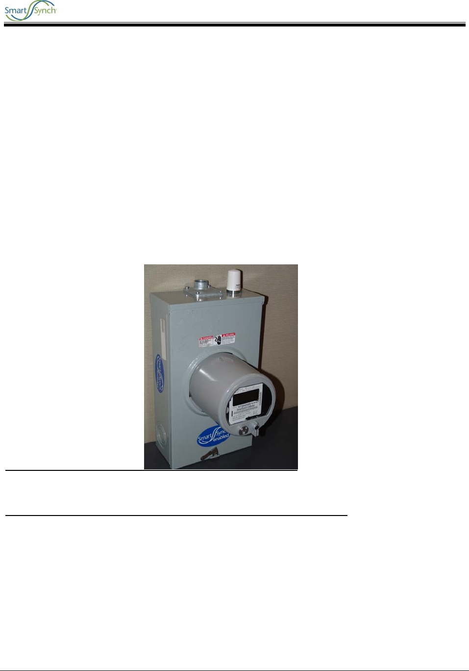
5.7 Acceptable Antenna Configuration
The tested antenna configurations are as follows:
1. Laird/Antenex pn TRA821/18503P GSM/GPRS Antenna (Meter Panel Mount).
2. Elster LANOB Antenna - pn 1B12150H01 (under cover).
The meter socket provides the ground plane when the Antenex pn TRA821/18503P antenna is properly
mounted to the meter panel metal socket. The Elster LANOB antenna is used in conjunction with Filter pn
1B12483 installed in series.
FIGURE 1 Mounting example of Laird/Antenex antenna directly to meter panel.
A3 GPRS Collector 5.0 SmartMeter User Guide
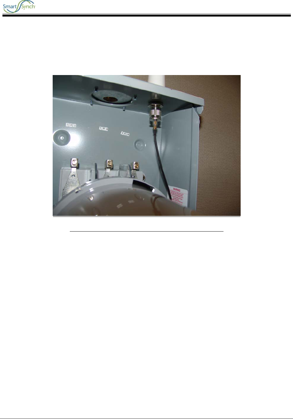
A3 GPRS Collector 5.0 17
FIGURE 2 Internal connection of Laird/Antenex antenna.