Itron IMU516 RF Module for Utility Gas Meter User Manual IMU200 Wiring Rev01
Silver Spring Networks RF Module for Utility Gas Meter IMU200 Wiring Rev01
Itron >
Contents
- 1. User Manual (Wiring)
- 2. User Manual (Installation)
User Manual (Wiring)

Doc: Silver Spring Networks - Confidential and Proprietary Page 1 of 4
IMU-200 Remote Mount
Pulser Wiring Information
Rev. 01, February 25, 2011
1 Overview
This document is intended to describe the wiring of the IMU-200 Remote Mount Module to
various partner devices. Internally these projects are referred to as ComGas 1 and ComGas 2.
The ComGas 1 consists of a Remote Mount IMU connected to a Riotronics pulser with a tamper
interface.
The ComGas 2 connects a Remote Mount IMU to a Mercury Corrector Unit, with support for
tamper and 2 channels of data, both uncorrected and corrected. This requires 4 channels of
input data to the IMU and tamper detection.
Doc: Silver Spring Networks - Confidential and Proprietary Page 2 of 4
2 Architecture
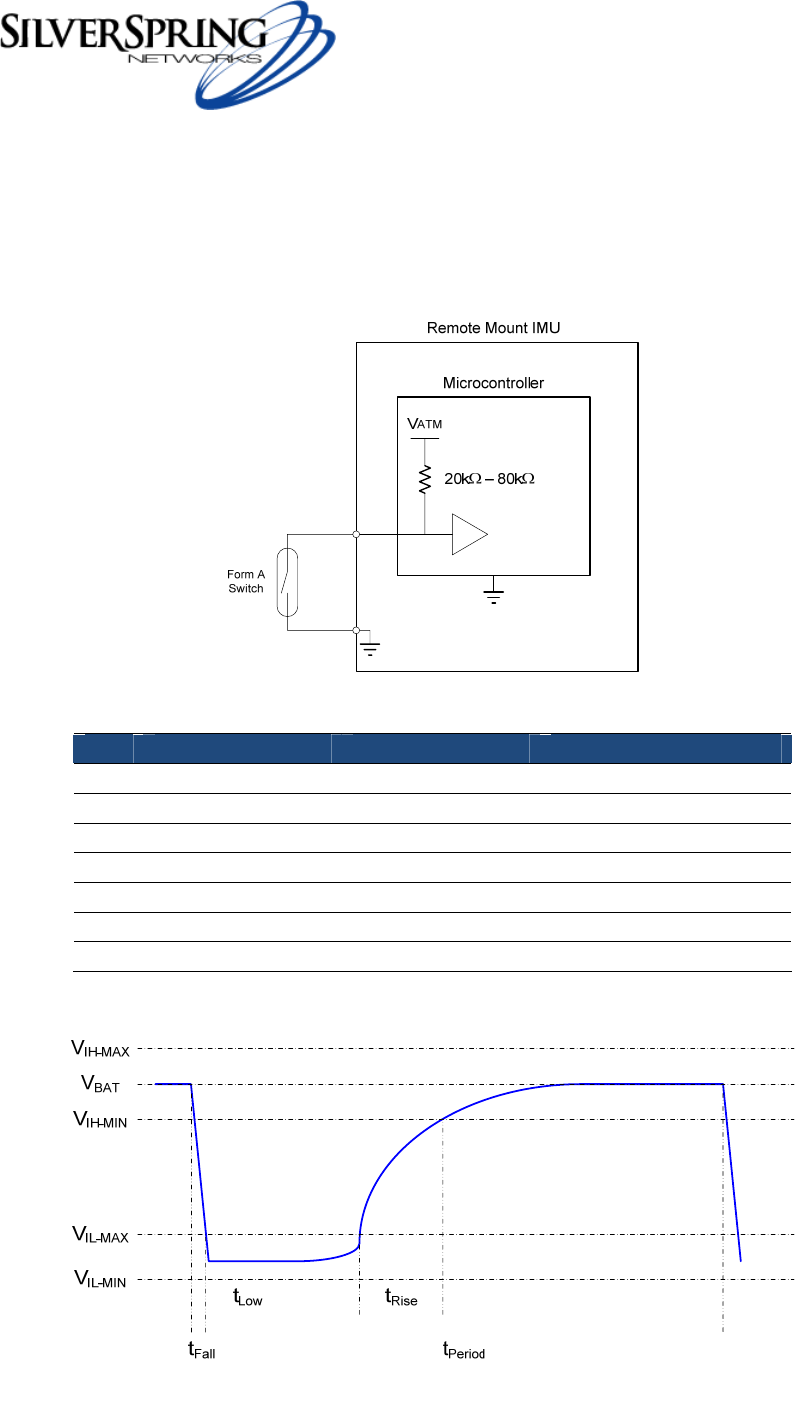
The Remote Mount IMU pulse input is compatible with a Form A (normally open) switch. The
voltage to the input is provided by an internal pull-up as shown in Figure 1. The voltage and
timing for a valid input pulse to the Remote Mount IMU is shown in Table 1 and Figure 2.
Figure 1 – Pulse Input Electrical Diagram
Table 1 – Pulse Electrical Parameters
Spec Nom. Min. Max.
VBAT 2.1V 1.9V 2.14V
VIL -- -0.5V 0.36V
VIH -- 1.5V 2.3V
tFall -- -- 10 ms
tLow -- 15 ms 100ms
tRise -- -- 140 ms
tPeriod -- 500 ms --
Figure 2 – Pulse Diagram

Doc: Silver Spring Networks - Confidential and Proprietary Page 3 of 4
2.1 Connection Definitions
The Remote Mount IMU has been tested with two devices to support current customer needs.
These devices are the Riotronics –PS4 model and the Mercury Corrector. Signal connections to
each of the devices are shown in Table 2.
Table 2 – PCBA Connections
Pin IMU-300 Riotronics –PS4 Mercury Corrector
1 Pulse IN Ch. 1 Pulse Out Pulse Out Ch. A +
2 Ground Ground Ground
3 Pulse IN Ch. 2 N/C Pulse Out Ch. B +
4 Ground N/C N/C
5 Pulse IN Ch. 3 N/C Pulse Out Ch. A Corrected +
6 Ground N/C N/C
7 Pulse IN Ch. 4 N/C Pulse Out Ch. B Corrected +
8 Ground N/C N/C
9 Tamper+ Tamper Tamper +
10 Tamper- N/C N/C
2.1.1 Riotronics –PS4
The Riotronics –PS4 is a single channel form A switch with tamper detection. The wire definitions
for the Riotronics –PS4 is as follows:
Table 3 – PCBA Connections
Pin Signal Wire
1 Pulse Out Red
2 Ground Black
3 Tamper Bare wire
w/ wire end sheath
2.1.2 Mercury Corrector
The Mercury Corrector uses differential channels for each of the signals, meaning that there is a
Pulse Out Ch. A + and a Pulse Out Ch. A -. All of the negative or return path signals should be
connected together at the Mercury Corrector unit and connected to the Ground wire on the cable
to the Remote Mount IMU.