Itron IMU518 Gas meter User Manual IMUGasInstall 14feb2011x
Silver Spring Networks Gas meter IMUGasInstall 14feb2011x
Itron >
User Manual

innovation in utility networking
Gas IMU Installation
and Configuration
February 14, 2011

2
© 2010 Silver Spring Networks | Company Confidential
Overview
•Remove existing index and prepare the meter
•Attach the tamper magnet holder
•Attach the index to the IMU
•Attach the IMU assembly to the meter
•Inspect
•Prepare IMU for programming

3
© 2010 Silver Spring Networks | Company Confidential
Safety First!
•Always follow applicable standards for safety!
•Refer to the meter documentation for further safety information.
•Follow your employer’s best practices.
•If you smell gas, report it to the utility.
•Do not use power tools!

4
© 2010 Silver Spring Networks | Company Confidential
RF Exposure Notice (509)
•The antenna of this transmitter must not be co-located or operating in conjunction with any other antenna
or transmitter.
•The device should be installed so that people will not come within 20 cm (8 in.) of the antenna.
•This equipment has been tested and found to comply with Part 15 of the FCC Rules. This equipment
generates, uses and can radiate radio frequency energy, and if not installed and used in accordance with
the instructions, may cause harmful interference to radio communications. However, there is no guarantee
that interference will not occur in a particular installation. If this equipment does cause harmful
interference to radio or television reception, which can be determined by turning the equipment off and
on, the user is encouraged to try to correct the interference by one or more of the following measures:
•Reorient or relocate the receiving antenna.
•Increase the separation between the equipment and receiver.
•Connect the equipment into an outlet on a circuit different from that to which the receiver disconnected.
•Consult the dealer or an experienced Radio/TV technician for help.
Modifications to the IMU not
expressly approved by Silver Spring Networks
may void your authority to operate the IMU.

5
© 2010 Silver Spring Networks | Company Confidential
Components and Tools
•Components:
•Tools:
–Flathead screw driver (capable of torque setting)
–Phillips screw driver (capable of torque setting)
–Nut driver
–Awl, scraper, wire brush
–Service magnet
–Guide pins Service magnet
Component Qty. Size Part Numbers
SSN IMU (top level,
includes hardware)
1 n/a 221-010001 (Am)
222-010001 (RW)
Index cover 1 n/a 976-000195 (Am)
976-000196 (RW)
Index cover screws 4 ¼-20” x 21/8”
10-24 x 21/4”
901-000067 (Am)
901-000053 (RW)
Index screws 2 8-32 x 3/16”
6-32 x 3/4”
901-000054 (Am)
901-000057 (RW)
Red tamper seals 2 n/a 976-000204
Tamper magnet holder
& magnet
1 n/a 976-000212 (Am)
976-000213 (RW)
6
© 2010 Silver Spring Networks | Company Confidential
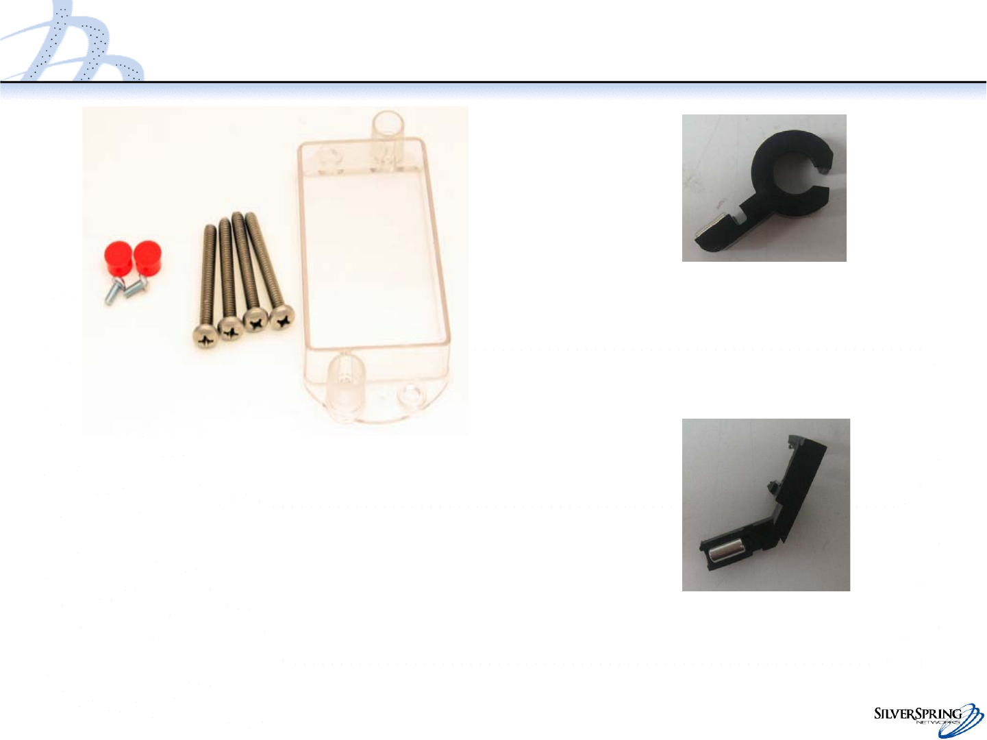
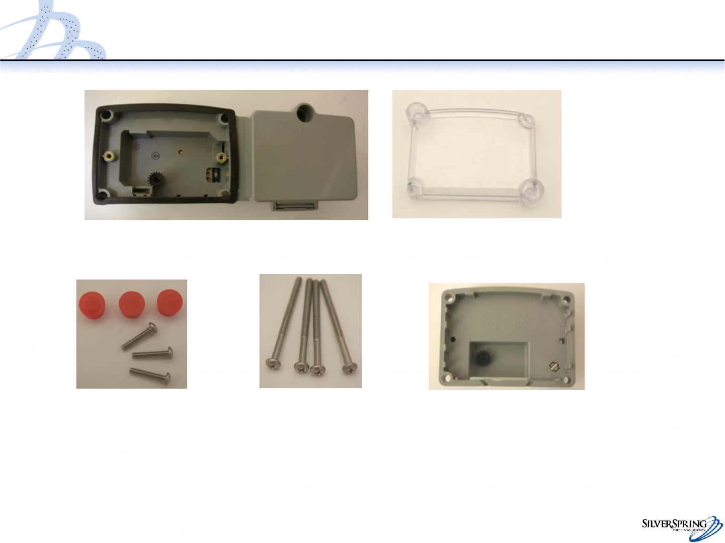
Components
Tamper magnet holder
and magnet for Rockwell
Index
cover
(American)
Index
screws
Index cover
screws
Tamper
seals
Tamper magnet holder
with magnet for American
7
© 2010 Silver Spring Networks | Company Confidential
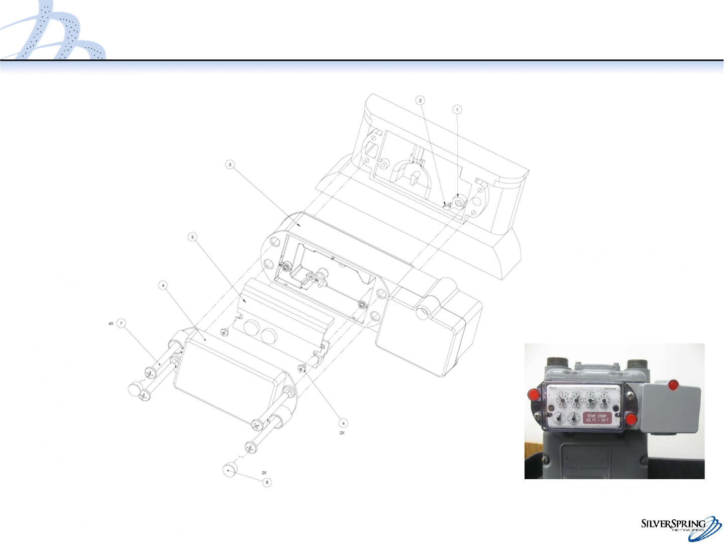
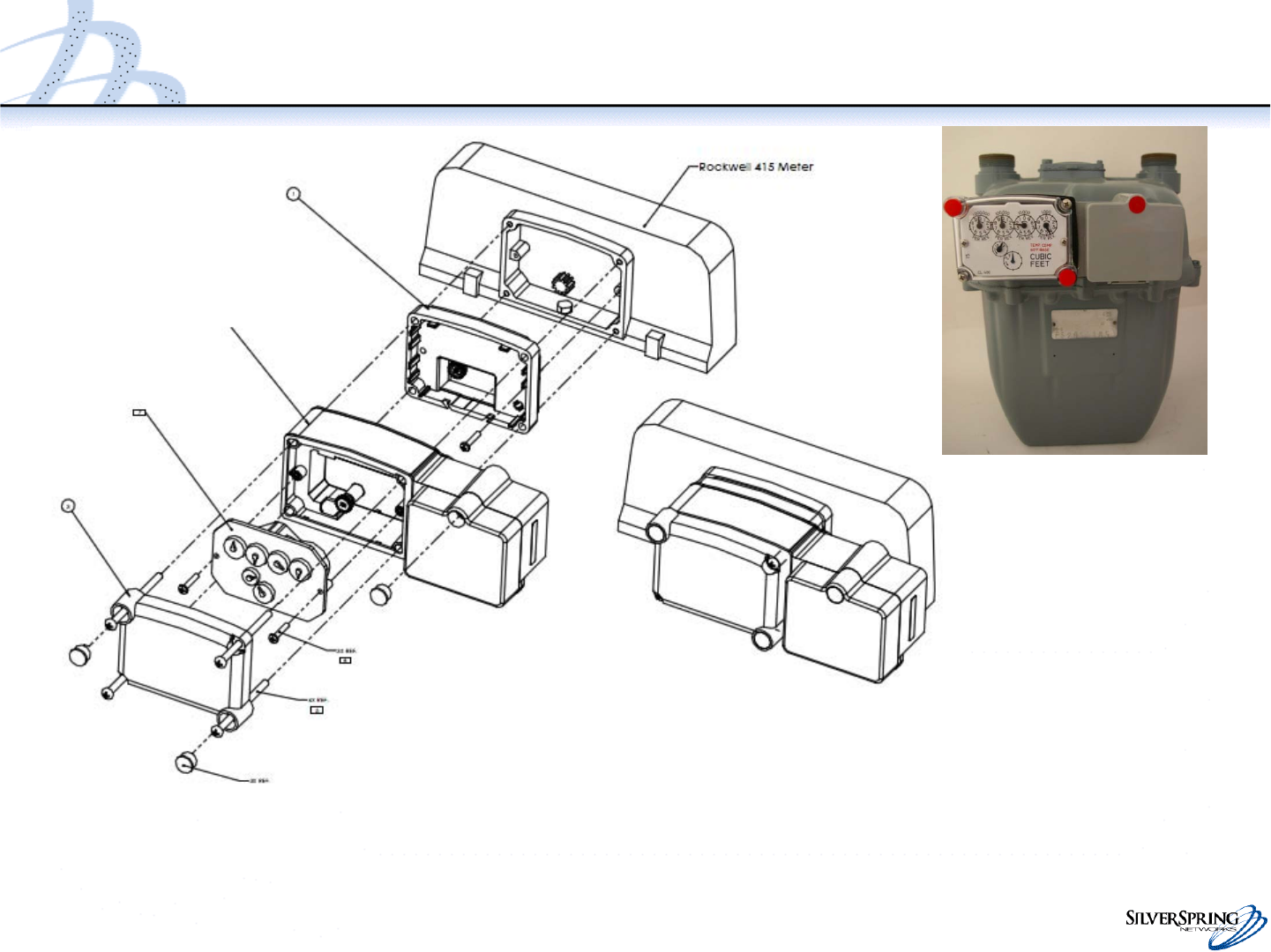
Assembly Drawing (American)
Index
cover
Index
screws
Index cover
screws
Tamper seals
Tamper magnet holder
(for American)
Tamper magnet
IMU
Index
Battery
compartment
¼-20” x 2.125”
Torque 10-11 in
lb
8-32 x 3/16”
Torque 8-10 in lb
8
© 2010 Silver Spring Networks | Company Confidential
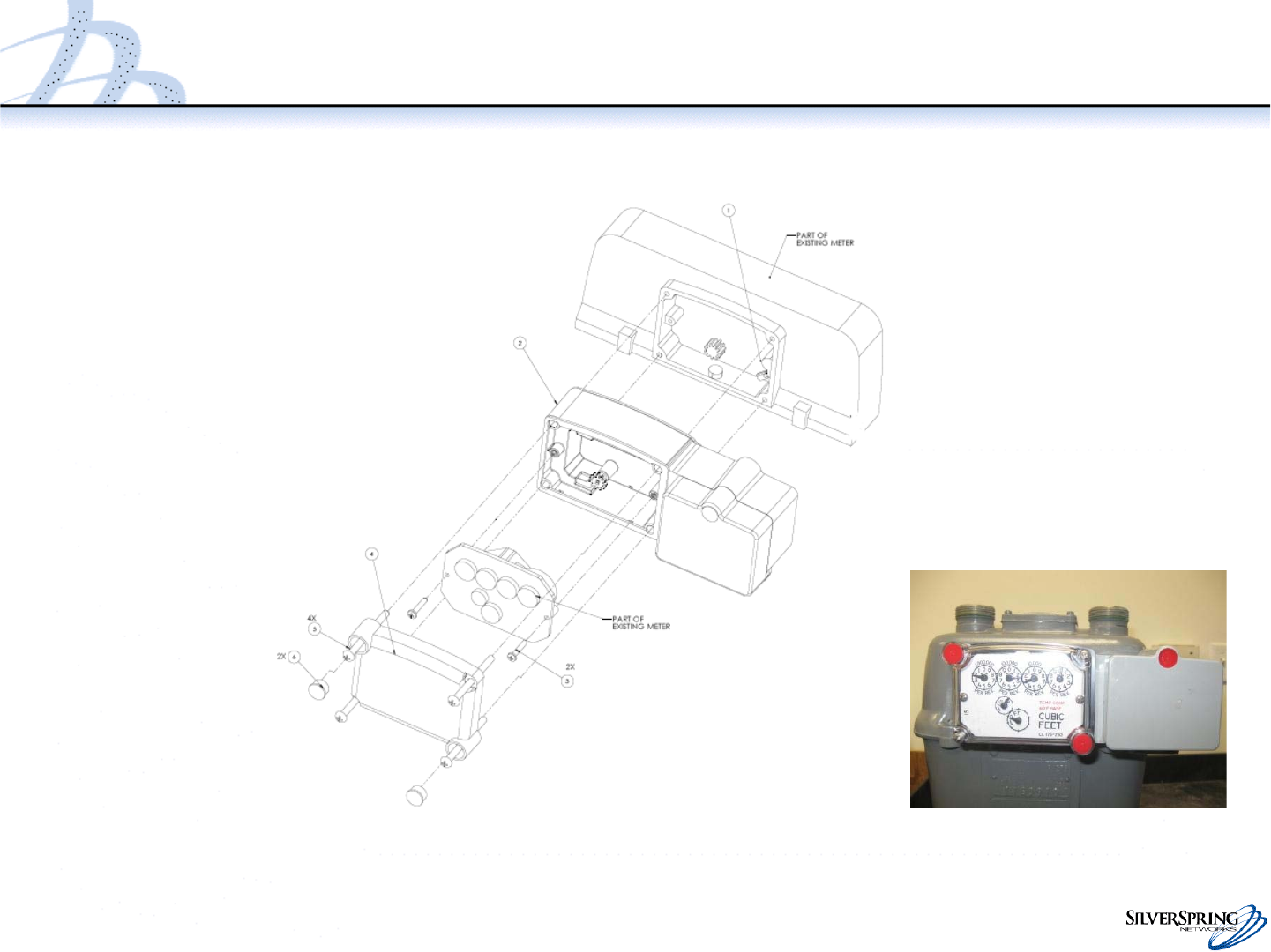
Assembly Drawing (Rockwell)
Index
cover Index screws
Index cover screws
Tamper seals
Tamper magnet holder
and magnet (for Rockwell)
IMU
Index
Battery
compartment
10-24 x 2.25”
Torque 6-8 in lb
6-32 x 3/4”
Torque 6-7 in lb
9
© 2010 Silver Spring Networks | Company Confidential
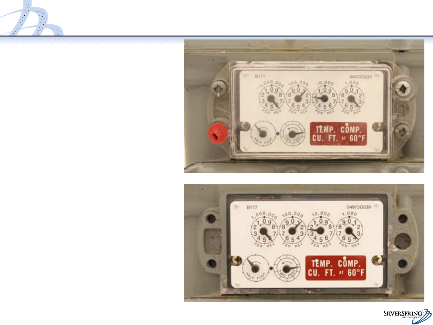
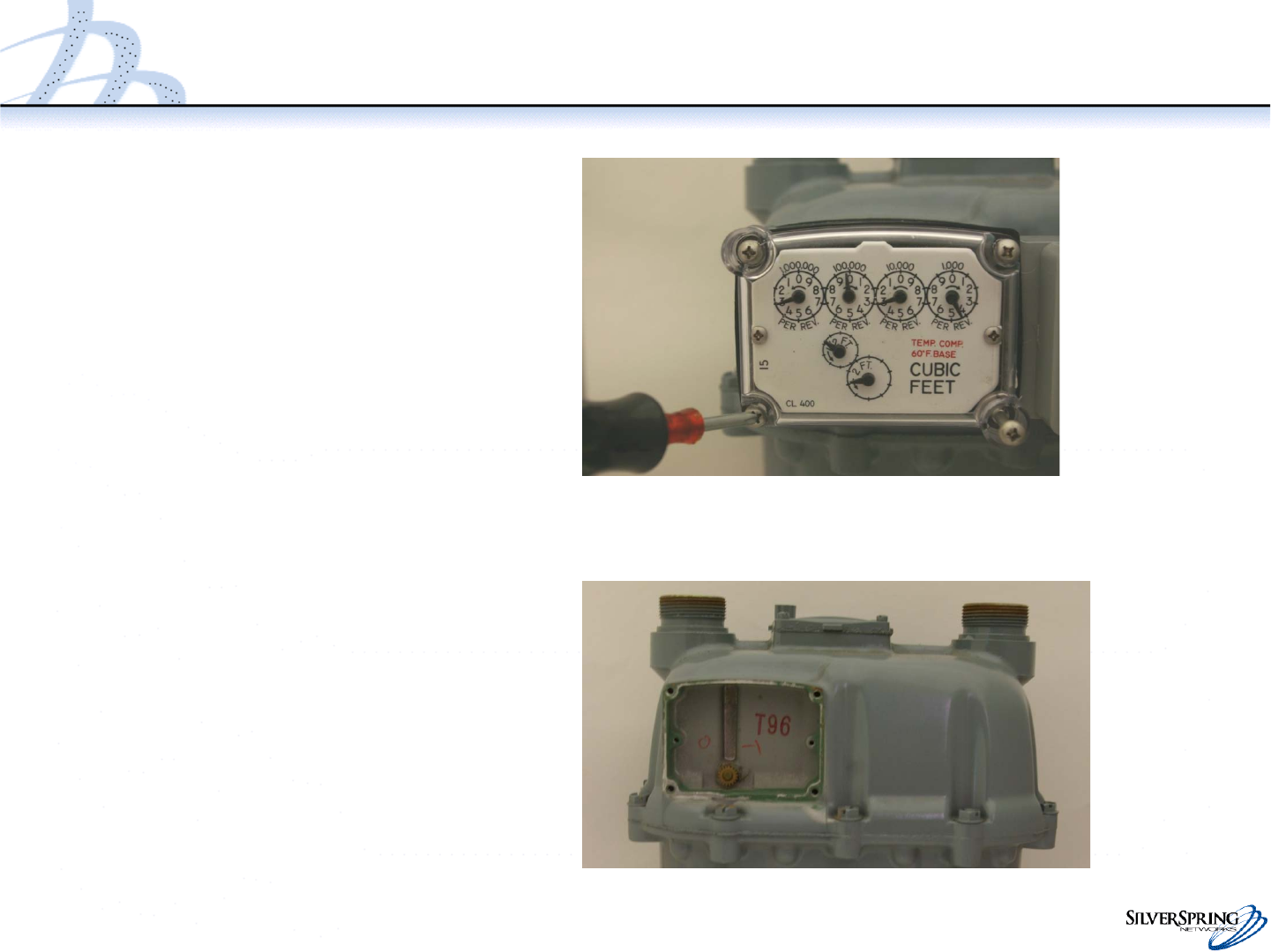
Remove Existing Cover & Prep Meter
•Remove the existing index cover
and index from the meter.
•Clean the meter index area
and make sure to remove
any remaining parts
of the old gasket.
10
© 2010 Silver Spring Networks | Company Confidential
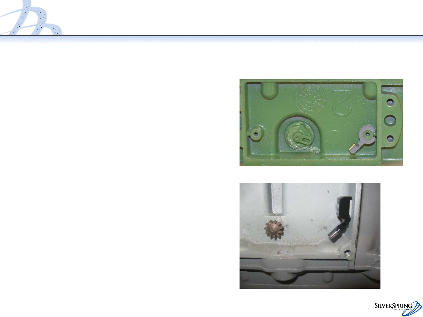
Attach the Tamper Magnet Holder
•On an American meter,
attach the magnet so that
the protrusion holding the
magnet points down and to
the left and the gap in the
circle fits around the
notch on the meter.
•On a Rockwell meter, attach the
magnet holder so that the
protrusion holding the magnet
points down and to the left and
the inner pin is inserted into
the index screw hole. American
American
American
Rockwell
11
© 2010 Silver Spring Networks | Company Confidential
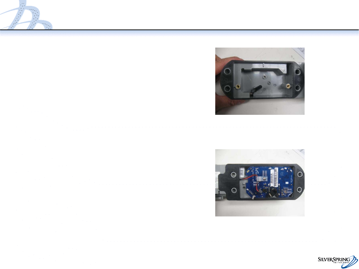
Inspect IMU
•Inspect the IMU, ensuring that
there is no visible damage.
•Check the front and rear gaskets.
Make minor placement
corrections as needed.
–The front gasket should adhere
to the enclosure and keep the
screw holes clear.
–The rear gasket should be
attached to the enclosure on the
left and right, and remain
straight in the middle such that
the gasket will seal between the
enclosure and meter. The
gasket must keep the screw
holes clear.
12
© 2010 Silver Spring Networks | Company Confidential
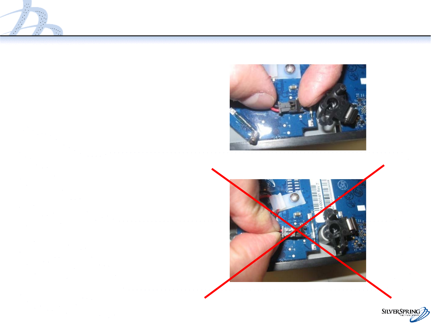
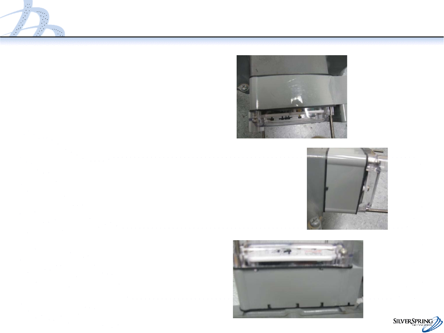
Connect Battery Cable Connector
•Gently plug in the battery cable
connector to the PCB, if it is not
already connected.
–The connectors are keyed. The
top side of the male connector
has a feature that fits into a slot
on the top side of the female
connector on the PCB.
–Orient the connectors before
attempting to connect.
–Carefully insert the male
connector while holding the
opposite end of the female
connector. Do not push the
male connector without holding
the opposite end of the female
connector.
13
© 2010 Silver Spring Networks | Company Confidential
Attach the Meter Index to the IMU
•Align the IMU drive train
with the index wriggler.
IMU Drive Train
Index Wriggler
14
© 2010 Silver Spring Networks | Company Confidential
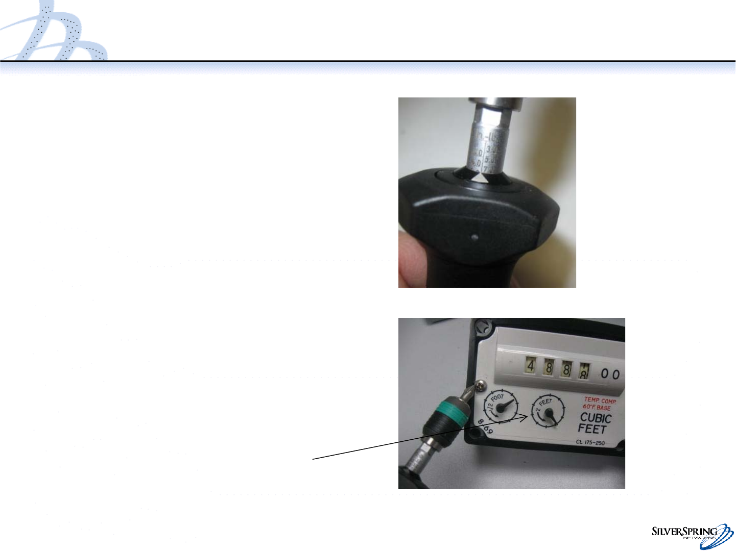
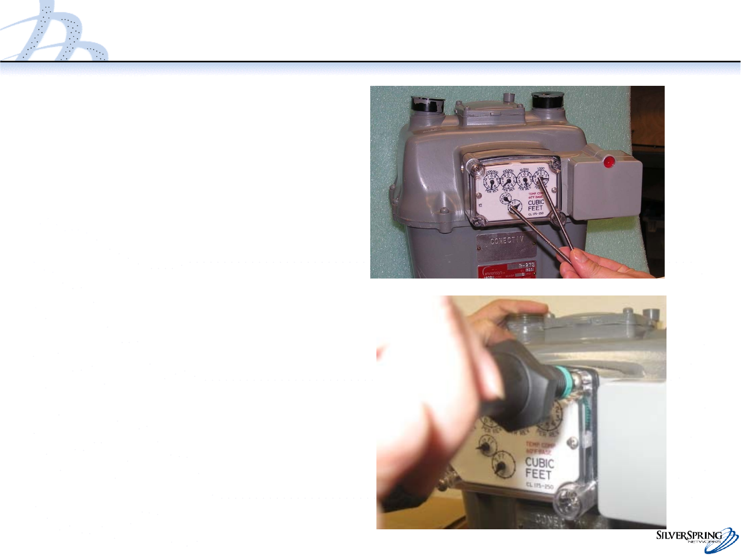
Attach Meter Index to IMU
•Use the two index screws
to firmly attach the index
to the IMU.
•Index screw torque:
–Rockwell: 6-7 inch pounds
–American: 8-10 inch pounds
•Rotate the drive shaft two turns from
the rear, clockwise or counter-
clockwise, and observe that the 2 foot
test hand also moves 2 turns. The test
hand should spin freely. If not, correct
by fixing or replacing the index or IMU.
Two rotations of the IMU drive shaft will
rotate the 2 ft drive hand two
rotations.
15
© 2010 Silver Spring Networks | Company Confidential
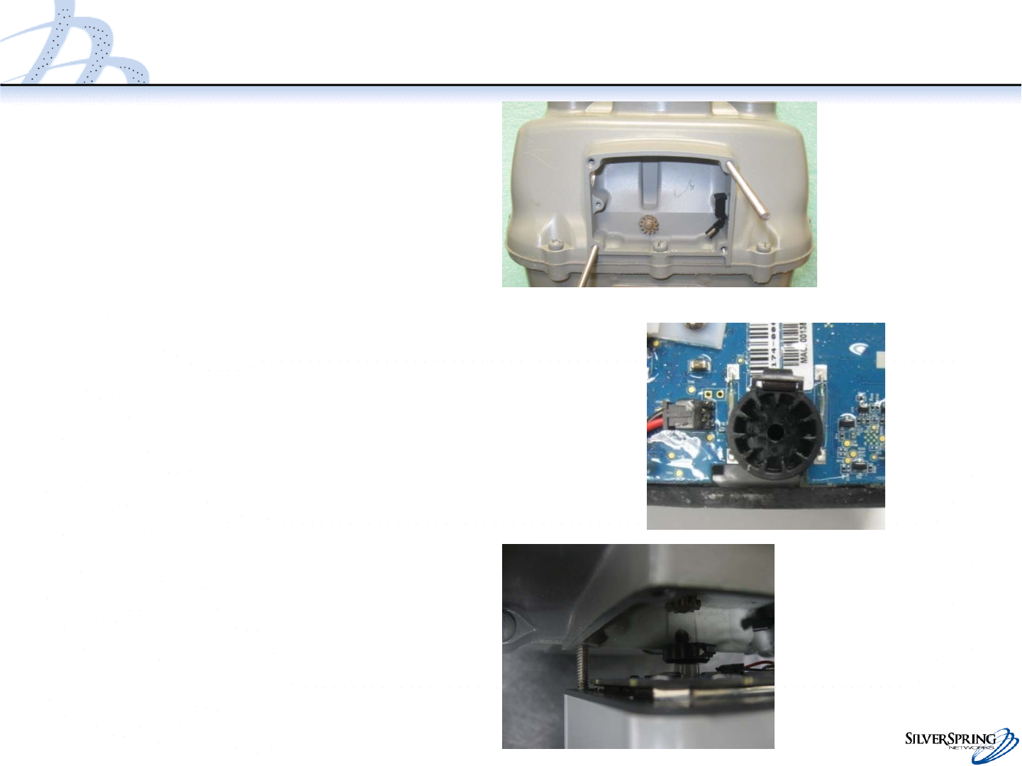
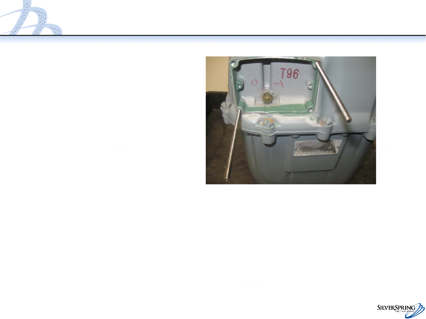
Attach IMU Assembly to Meter
•Temporarily fasten the guide pins
to the meter (3-4 threads into
the meter). You will remove
these in a later step.
•Using the guide pins, align the
IMU to the meter and match the
meter wriggler to the IMU drive
by adjusting the index test hand.
–On the Rockwell meter, rotate
the magnet to 12 o’clock to
avoid the screw in the index
well.
–Watch (from the side or top) the
IMU drive link to the meter
wriggler.
•On the American meter, the
pin goes into the slot.
•On the Rockwell meter, the
cup fits over the wriggler
(meter gear).
16
© 2010 Silver Spring Networks | Company Confidential
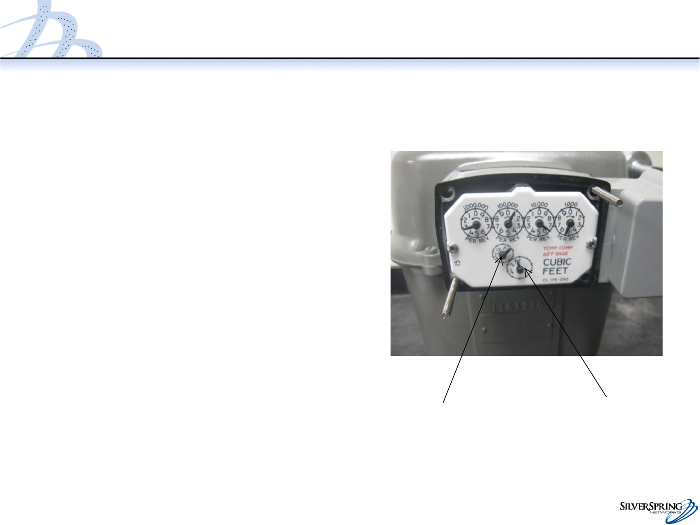
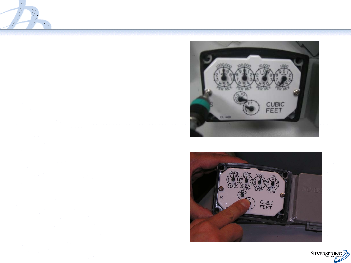
Attach IMU Assembly to Meter
•Hold the enclosure against the meter to
maintain proper alignment to perform
the following checks:
–If no gas is flowing through the meter,
verify that the half cubic ft test hand
rotates approximately 180 degrees when
turned gently by hand
–If gas is flowing through the meter, you
should see the test hands rotating. You
do not need to manually rotate the test
hand.
•Verify that:
–There are no clicking or snapping
sounds
–There is no gap between the meter and
IMU
–The rear gasket seals the meter to the
IMU
Half foot test hand Two foot test hand
17
© 2010 Silver Spring Networks | Company Confidential
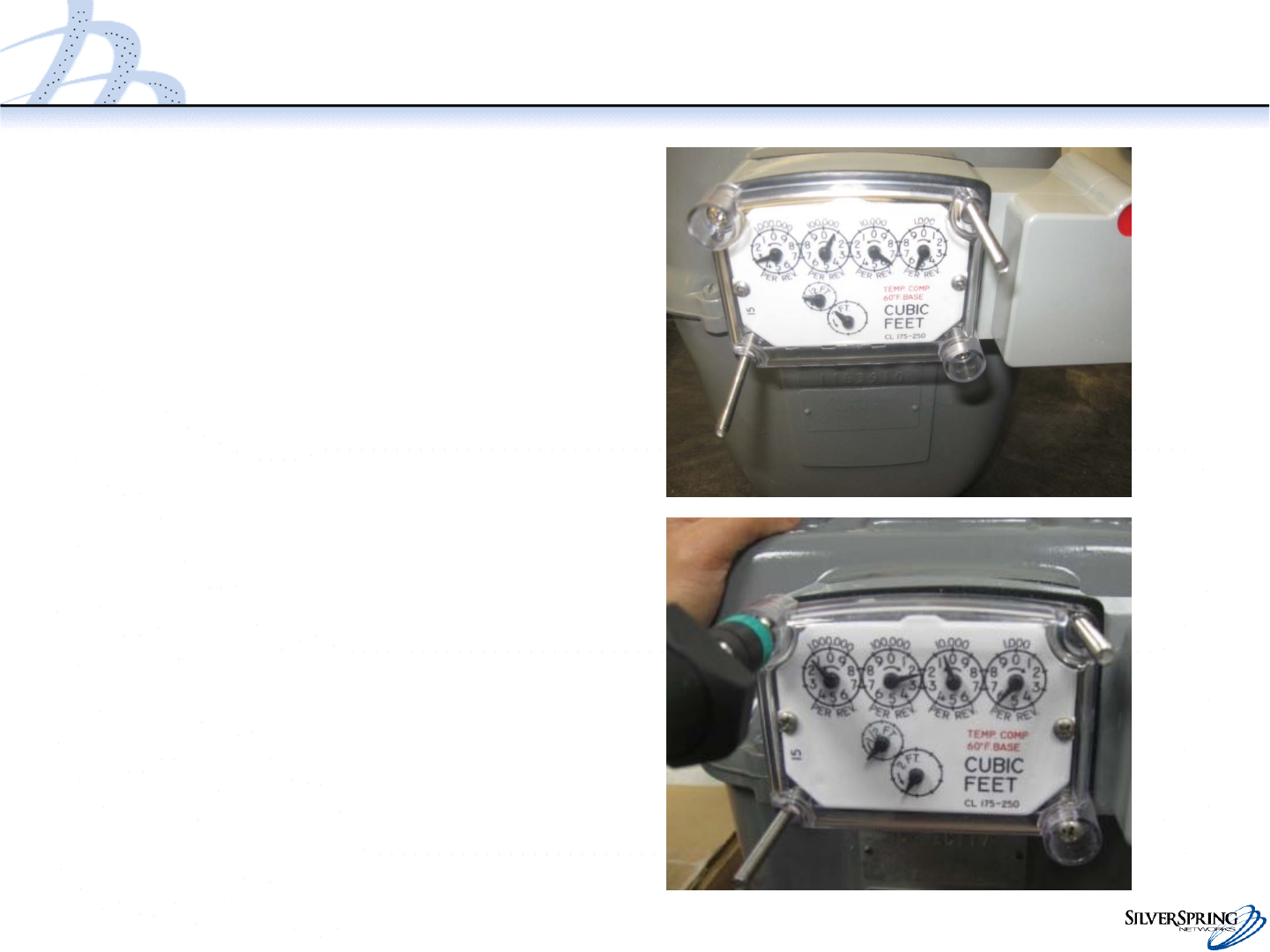
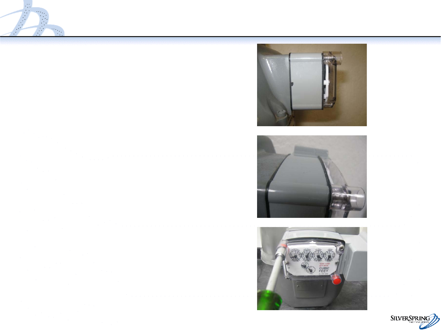
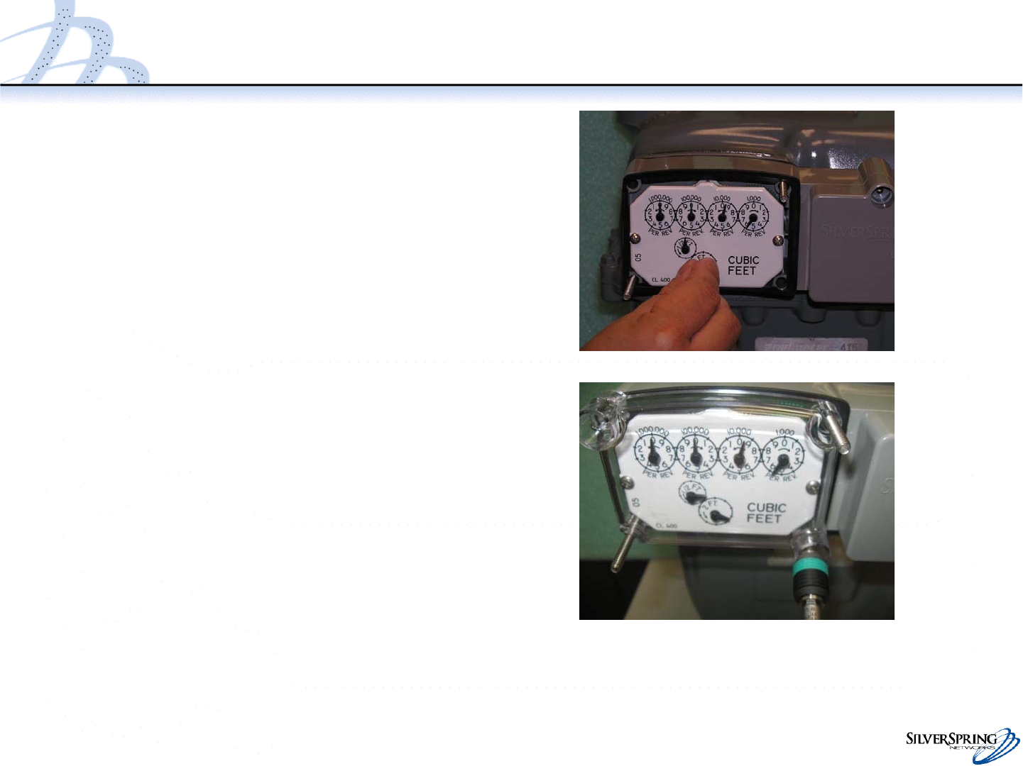
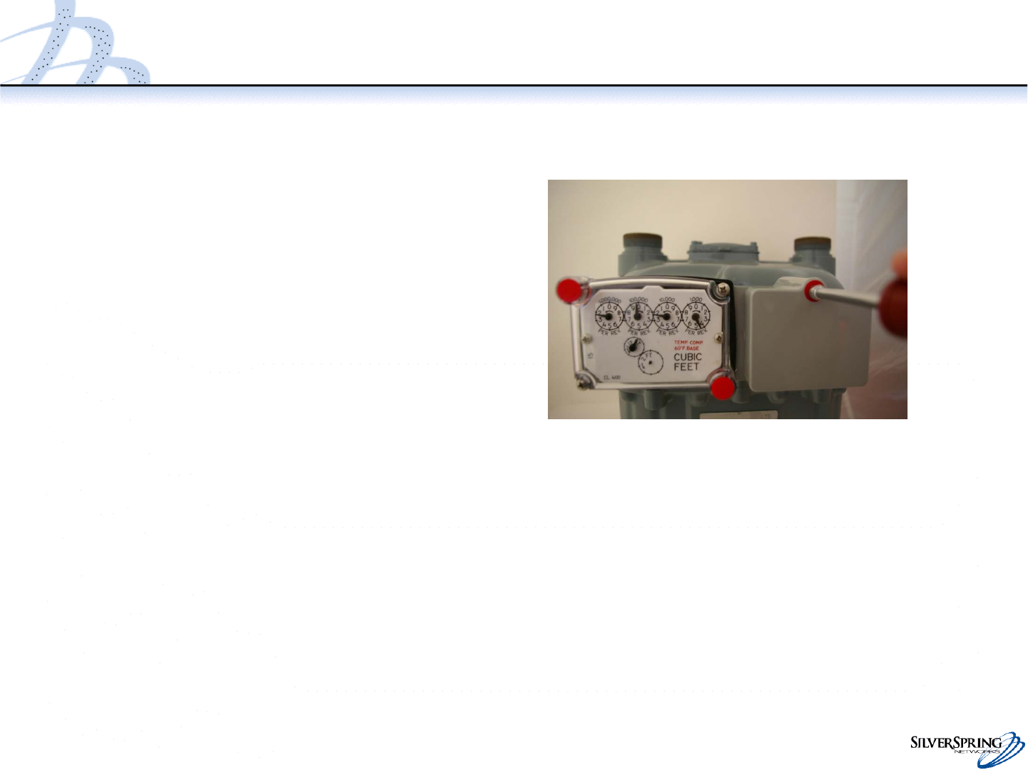
Attach IMU Assembly to Meter
•If you hear clicking or snapping, or if
there is a gap or a poor gasket seal,
remove the IMU and reinstall.
Repeat the verification checks.
•Attach the index cover and 2
screws to the meter and IMU as
shown. On a Rockwell meter, the
curved side of the index cover goes
on top. The red tamper plugs will fit
to the upper left and lower right
corners.
•Tighten the 2 screws.
Torque:
–Rockwell: 6-8 inch pounds
–American: 10-11 inch pounds
18
© 2010 Silver Spring Networks | Company Confidential
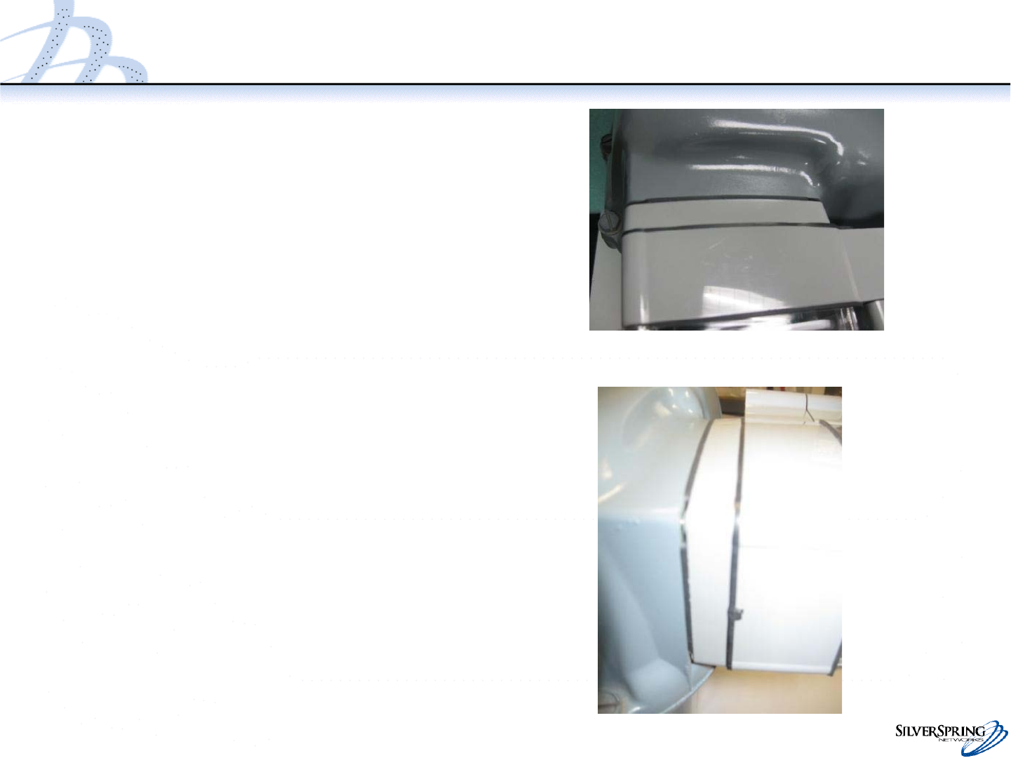
Inspect Gaskets
•Verify that the front and rear
gaskets seal the mating surfaces
all the way around the IMU and
index cover.
•If the gaskets have not seated
correctly, remove all the cover
screws, adjust the gasket
position, and reinstall the IMU.
19
© 2010 Silver Spring Networks | Company Confidential
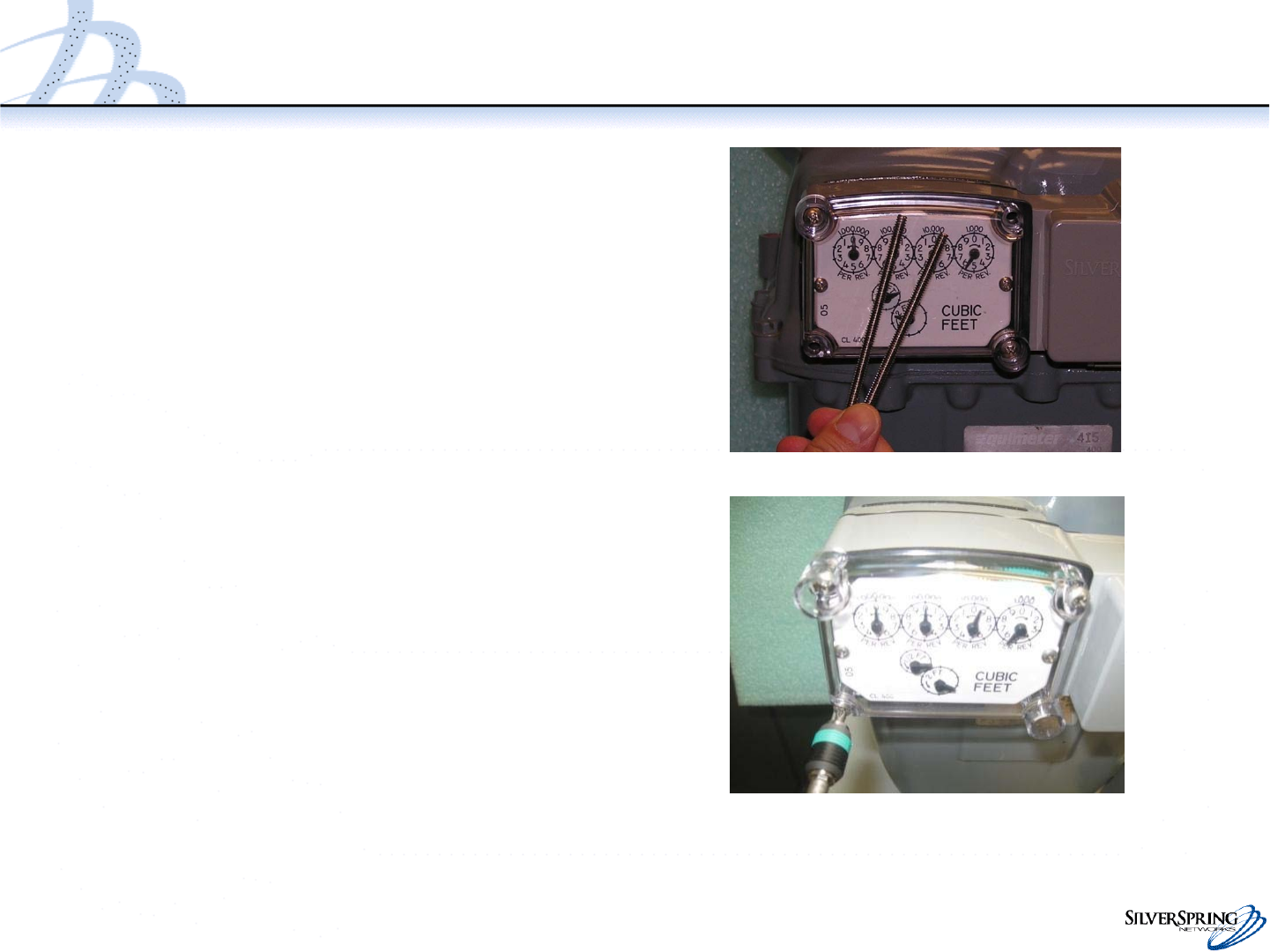
Attach IMU Assembly to Meter
•Remove the guide pins
•Install the remaining 2 screws
Install the remaining 2 screws
and tighten
Torque:
–Rockwell: 6-8 inch pounds
–American: 10-11 inch pounds
20
© 2010 Silver Spring Networks | Company Confidential
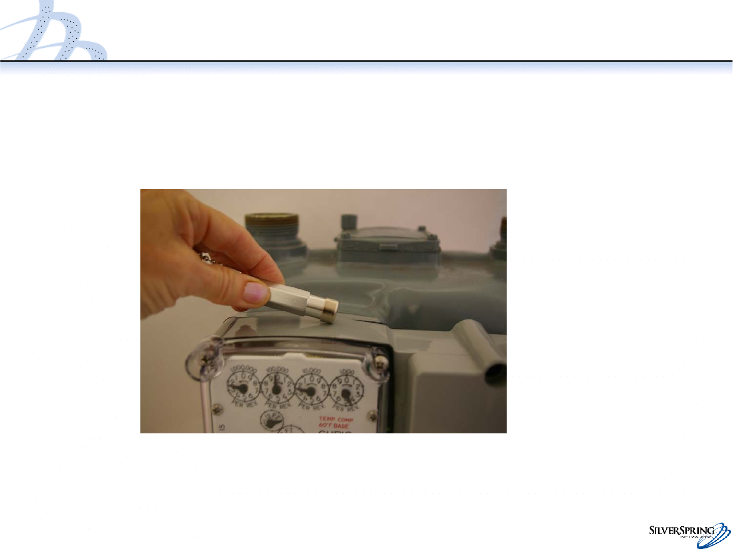
Inspect the gaskets and install the tamper seals
•Re-inspect the front and rear
gaskets to ensure that they
form a seal between the
index cover, enclosure, and
meter.
•Use a nut driver to push the
three tamper seals into the
openings on the IMU (2 in the
index cover and 1 in the
battery door).
21
© 2010 Silver Spring Networks | Company Confidential
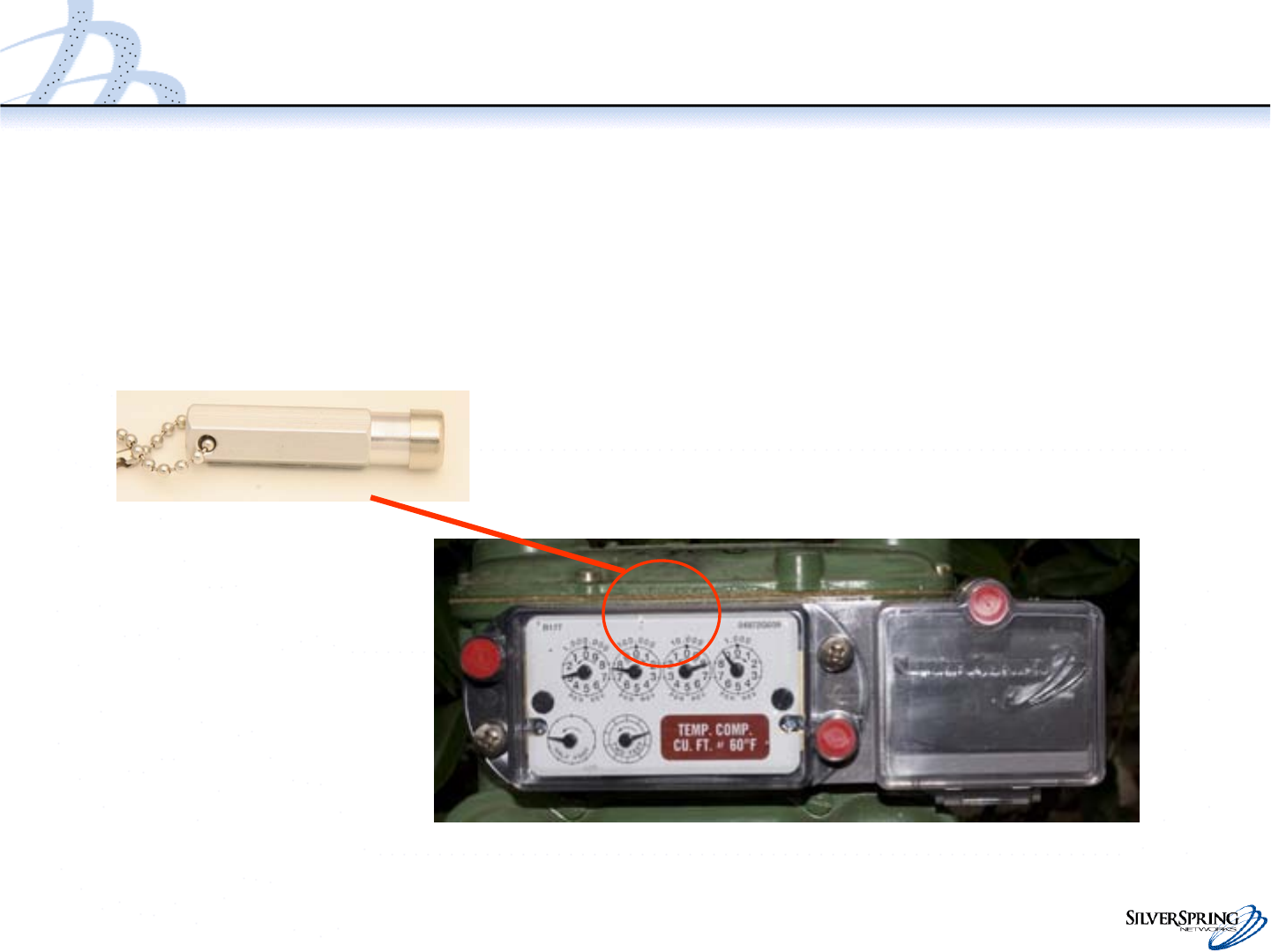
Prepare the IMU for Programming
•Slowly pass the service magnet once (for 2 to 5 seconds) over the top of the IMU.
•Doing so wakes up the IMU, enabling you to program it.

innovation in utility networking
Rockwell 415
Gas IMU Installation
and Configuration
January 28, 2011

23
© 2010 Silver Spring Networks | Company Confidential
Rockwell 415 IMU Retrofit
Overview
•Check the components and tools list.
•Remove the index cover and index.
•Fasten the adapter plate to the meter.
•Fasten the meter index to the IMU.
•Fasten the IMU to the meter.
•Fasten the index lens cover and the tamper seals.
•Inspect
•Prepare the IMU for programming.

24
© 2010 Silver Spring Networks | Company Confidential
Check the Components and Tools List
•Components:
•Tools:
– Flathead screw driver (capable of torque setting)
– Phillips screw driver (capable of torque setting)
– Nut driver
– Awl, scraper, wire brush
– Service magnet
– Guide pins Service magnet
Component Qty. Size Part Numbers
Silver Spring Networks
IMU
1 n/a 178-000101 rev 06
Adapter system 1 n/a 178-000098 rev 02
Index cover 1 n/a 976-000196 rev 1
Index cover screws 4 10-24 X 2.75” L 901-000061 rev 01
Index screws 3 6-32 X ¾” L 901-000063 rev 01
Red tamper seals 3 n/a 976-000203 rev 1
25
© 2010 Silver Spring Networks | Company Confidential
Components
Index screws Index cover screws
Tamper seals
Adapter plate
IMU Index cover
26
© 2010 Silver Spring Networks | Company Confidential
Assembly Drawing (Rockwell 415)
Rockwell 415
assembly
Index cover screws
Index screws and
adapter plate screw
6-32 x 3/4”
Torque 6-7 in lb
10-24 x 2.75”
Torque 6-8 in lb
27
© 2010 Silver Spring Networks | Company Confidential
Remove the Index Cover and Index
•Remove the existing index
cover and index from the meter.
•Clean the meter index area
and make sure to remove
any remaining parts of the
old gasket.
28
© 2010 Silver Spring Networks | Company Confidential
Install the Guide Pins
•Temporarily fasten the guide
pins to the meter (3-4 threads
into the meter). You will
remove these in a later step.
29
© 2010 Silver Spring Networks | Company Confidential
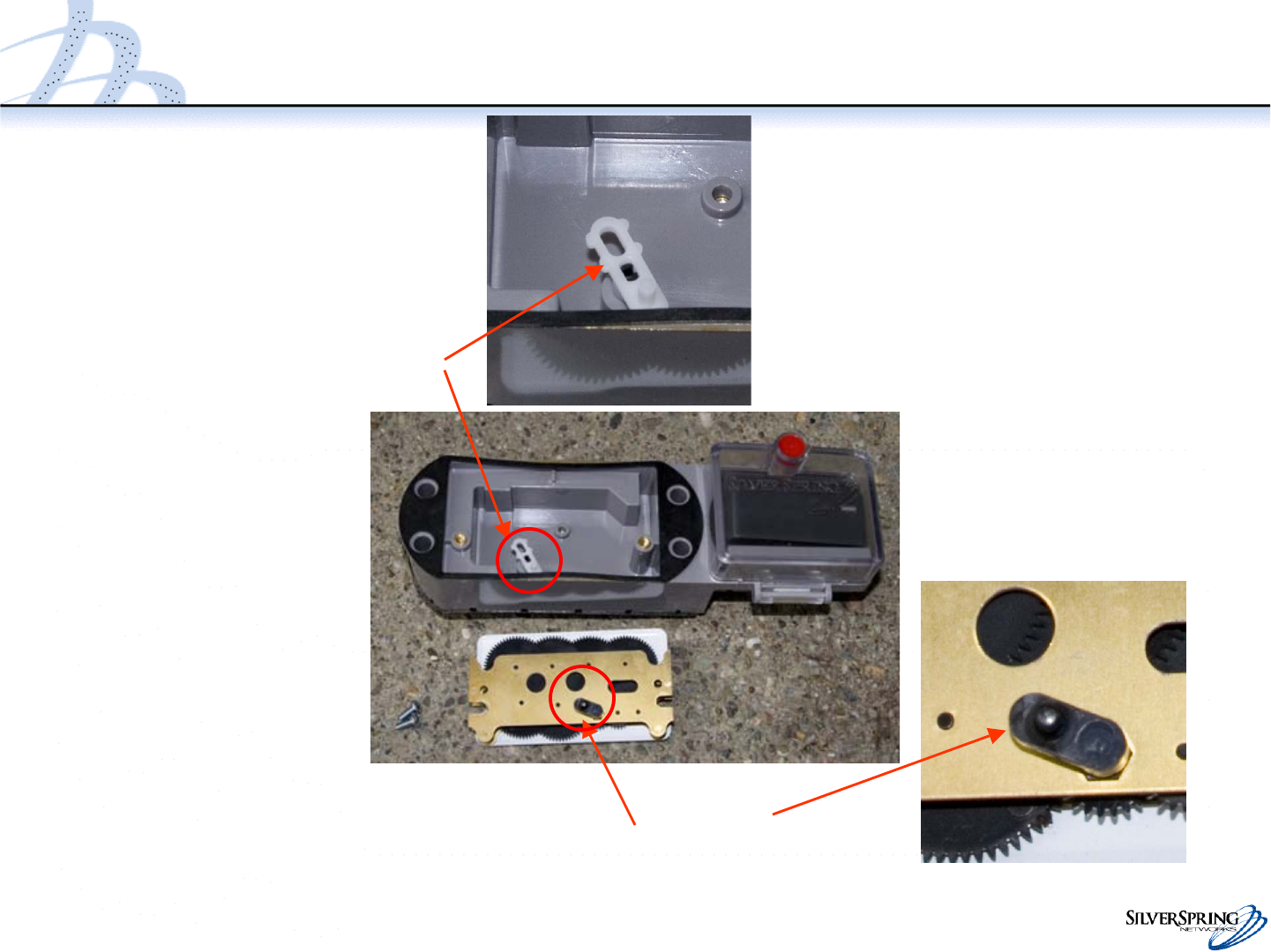
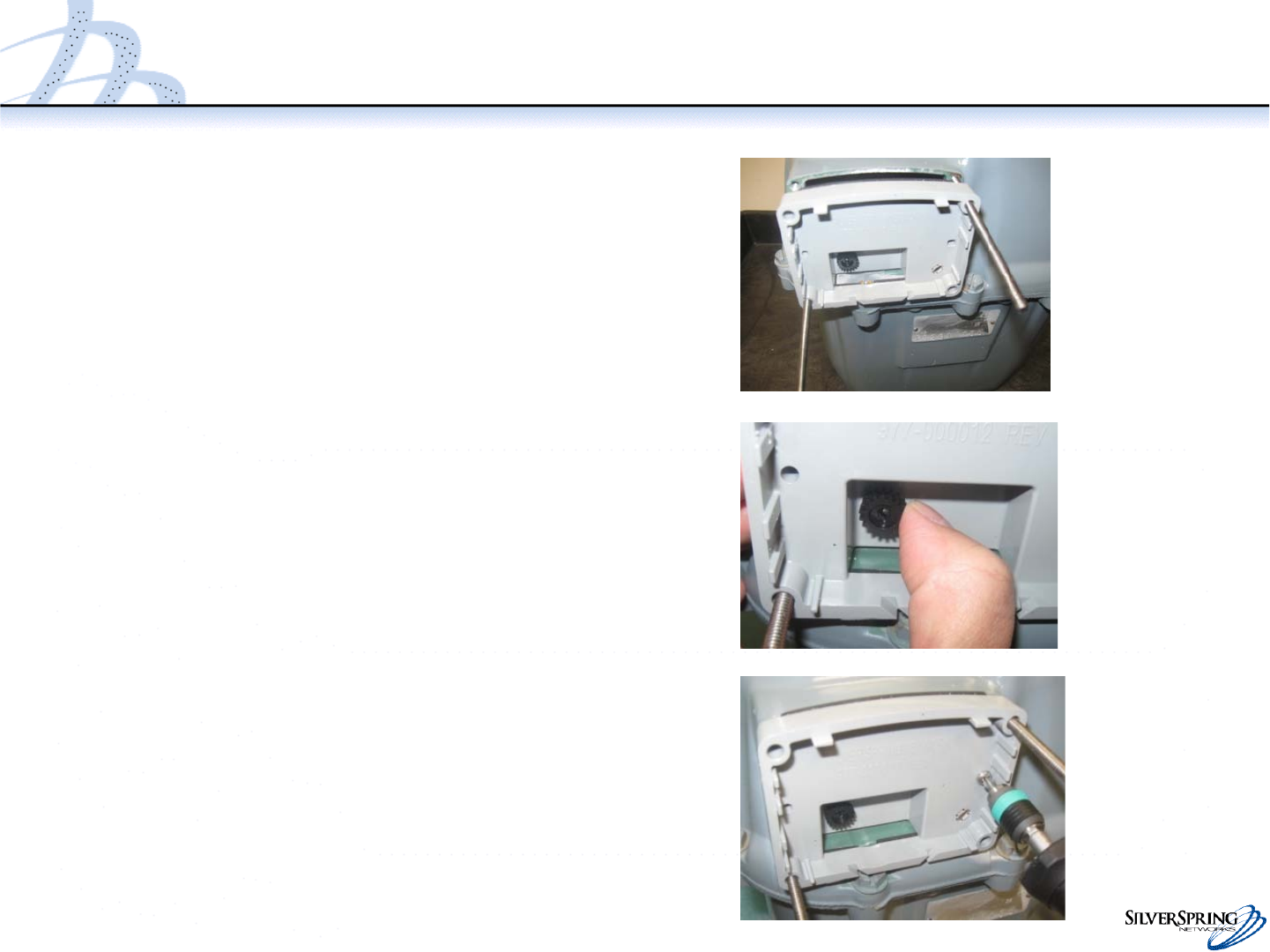
Fasten the Adapter Plate to the Meter
•Position the adapter plate pin
into the center left hole on the
meter and seat the adapter
plate onto the meter.
•Verify proper engagement of
the gears. The gear should
rotate at least 120 degrees.
•Position an index screw in the
center right hole and fasten
the adapter using 6-7 in-lbs of
torque.
30
© 2010 Silver Spring Networks | Company Confidential
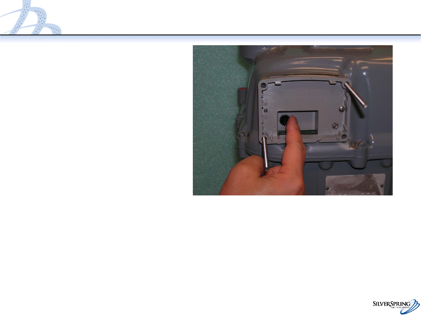
Fasten the Adapter Plate to the Meter (continued)
•If gas is not passing through
the meter, rotate the gear on
the plate clockwise until you
feel it engage with the meter
wriggler. The gear should
rotate at least 120 degrees.
•If gas is passing through the
meter, the gear should rotate
in conjunction with the meter.
•You should not hear any
clicking or snapping sounds.
31
© 2010 Silver Spring Networks | Company Confidential
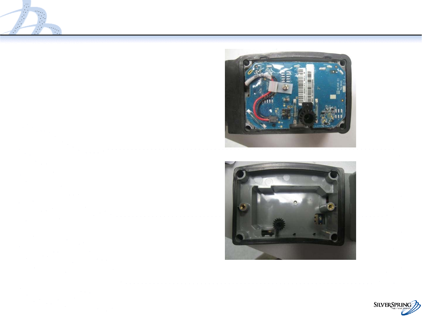
Inspect IMU
•Inspect the IMU, ensuring that
there is no visible damage.
•Check the front and rear gaskets.
Make minor placement
corrections as needed.
–The front gasket should adhere
to the enclosure and keep the
screw holes clear.
–The rear gasket should be
attached to the enclosure on the
left and right, and remain
straight in the middle such that
the gasket will seal between the
enclosure and meter. The
gasket must keep the screw
holes clear.
32
© 2010 Silver Spring Networks | Company Confidential
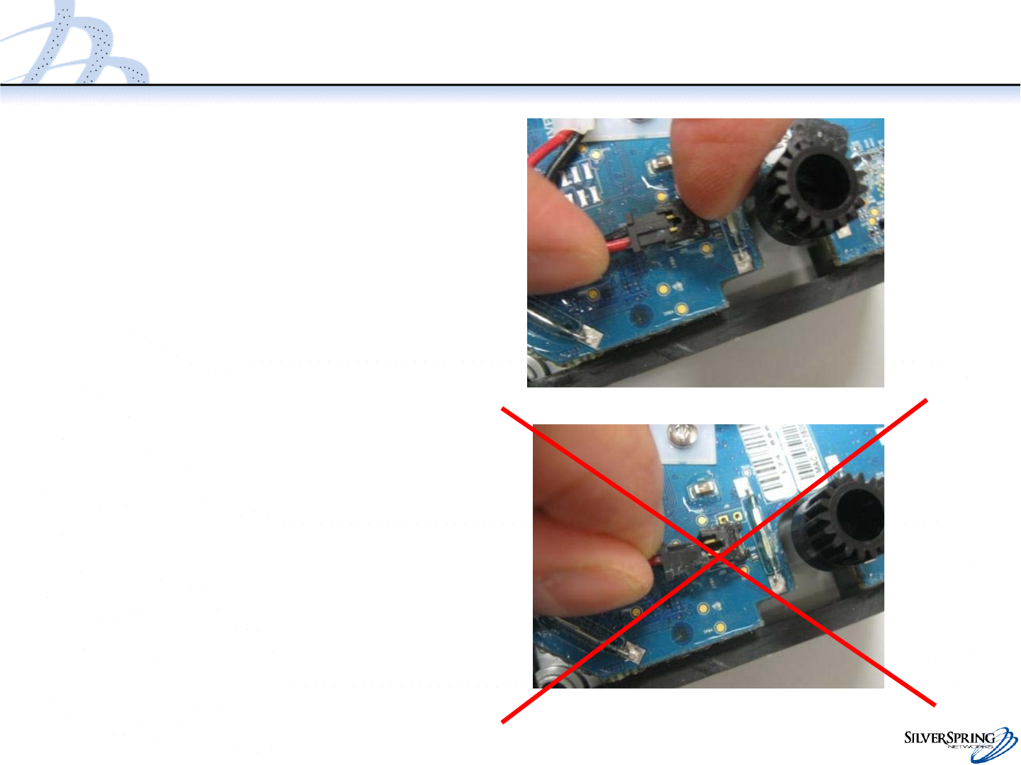
Connect Battery Cable Connector
•Gently plug in the battery cable
connector to the PCB, if it is not
already connected.
–The connectors are keyed. The
top side of the male connector
has a feature that fits into a slot
on the top side of the female
connector on the PCB.
–Orient the connectors before
attempting to connect.
–Carefully insert the male
connector while holding the
opposite end of the female
connector. Do not push the
male connector without holding
the opposite end of the female
connector.
33
© 2010 Silver Spring Networks | Company Confidential
Fasten the Meter Index to the IMU
•Attach the meter index to the
IMU with two index screws
using 6-7 in-lbs of torque.
•Make sure that the gears are
engaged and not bound up.
The test hands should move
freely, and in conjunction with
the IMU drive.
34
© 2010 Silver Spring Networks | Company Confidential
Fasten the IMU to the meter
•Make sure the gears are
engaged and not bound by
rotating the test hand.
•Attach the index cover and 2
screws to the meter and IMU
as shown.
•Tighten the 2 screws.
Torque: 6-8 inch pounds
35
© 2010 Silver Spring Networks | Company Confidential
Attach IMU Assembly to Meter
•Hold the enclosure against the meter to
maintain proper alignment to perform
the following checks:
–If no gas is flowing through the meter,
verify that the half cubic ft test hand
rotates approximately 120 degrees when
turned gently by hand
–If gas is flowing through the meter, you
should see the test hands rotating. You
do not need to manually rotate the test
hand.
•Verify that:
–There are no clicking or snapping
sounds
–The gaskets are sealed and there is no
gap between the meter, IMU, adapter
plate, and cover.
36
© 2010 Silver Spring Networks | Company Confidential
Fasten the IMU to the meter
•Remove the guide pins
•Install the remaining 2
screws
Torque: 6-8 inch pounds

37
© 2010 Silver Spring Networks | Company Confidential
Inspect the Gaskets
•Verify that the front and rear
gaskets are properly seated all
the way around the IMU. If not,
remove and reinstall the IMU.
38
© 2010 Silver Spring Networks | Company Confidential
Install the tamper seals
•Use a nut driver to push the three
tamper seals into the openings on
the IMU.
39
© 2010 Silver Spring Networks | Company Confidential
Prepare the IMU for Programming
Slowly pass the service magnet once (for 2 to 5 seconds) over the top of the IMU.
This activates the IMU so you can program it. (tamper seals not shown)