Contents
- 1. Manual
- 2. Host Manual
Manual

5015 B.U. Bowman Drive Buford, GA 30518 USA Voice: 770-831-8048 Fax: 770-831-8598
Certification Exhibit
FCC ID: SK9OW1
IC: 864G-OW1
FCC Rule Part: 15.247
IC Radio Standards Specification: RSS-247
ACS Project Number: 16-0295
Manufacturer: Itron, Inc.
Model: OW1
Manual

CAM Module, Model OW1
OW1
OpenWay® Riva™ CAM / ACT
Technical Reference Guide
Effective Date: August, 2016

CAM Module, Model OW1
Revision History
The following table describes the changes to this document for each revision of the OW1 module:
Revision Date Description of Change
A August, 2016 Initial Release

CAM Module, Model OW1
Labeling
The following requirements will be applied to any products that use this module:
The end product or host label will include the following text:
• Contains:
• FCC ID: SK9OW1
• IC: 864G-OW1, Model: OW1
The user’s manual for any product that contains this module will contain the following text. If the device is large
enough, then this will also be placed on the label.
“This device complies with Part 15 of the FCC Rules. Operation is subject to the following two conditions: (1) this
device may not cause harmful interference, and (2) this device must accept any interference received, including
interference that may cause undesired operation.”
Regulatory Compliance
The user’s manual for any product that contains this module will contain the following text:
FCC Part 15, Class B
This equipment has been tested and found to comply with the limits for a Class B digital device, pursuant to Part 15 of
the FCC Rules. These limits are designed to provide reasonable protection against harmful interference in a residential
installation. This equipment generates uses and can radiate radio frequency energy and, if not installed and used in
accordance with the instructions, may cause harmful interference to radio communications. However, there is no
guarantee that interference will not occur in a particular installation. If this equipment does cause harmful interference
to radio or television reception, which can be determined by turning the equipment off and on, the user is encouraged to
try to correct the interference by one or more of the following measures:
• Reorient or relocate the receiving antenna.
• Increase the separation between the equipment and receiver.
• Connect the equipment into an outlet on a circuit different from that to which the receiver is connected.
• Consult the dealer or an experienced radio/TV technician for help.
Changes or modifications to this device not expressly approved by Itron,
Inc. could void the user’s authority to operate the equipment.
Innovation, Science and Economic Development Canada (ISED)
This Class B digital apparatus meets all requirements of the Canadian Interference Causing Equipment Regulations.
Operation is subject to the following two conditions: (1) this device may not cause harmful interference, and (2) this
device must accept any interference received, including interference that may cause undesired operation.
Cet appareillage numérique de la classe B répond à la norme Canadienne sur le matériel brouilleur. L'opération est
sujette aux deux conditions suivantes: (1) ce dispositif ne peut pas causer d'interférence nocive, et (2) ce dispositif doit
accepter n'importe quelle interférence reçue, y compris les interférences pouvant entraîner un fonctionnement
indésirable.

CAM Module, Model OW1
Under Innovation, Science and Economic Development Canada regulations, this radio transmitter may only operate
using an antenna of a type and maximum (or lesser) gain approved for the transmitter by Innovation, Science and
Economic Development Canada. To reduce potential radio interference to other users, the antenna type and its gain
should be so chosen that the equivalent isotropically radiated power (e.i.r.p.) is not more than that necessary for
successful communication.
Conformément à la réglementation d'Industrie Canada, le présent émetteur radio peut fonctionner avec une
antenne d'un type et d'un gain maximal (ou inférieur) approuvé pour l'émetteur par Industrie Canada. Dans le
but de réduire les risques de brouillage radioélectrique à l'intention des autres utilisateurs, il faut choisir le
type d'antenne et son gain de sorte que la puissance isotrope rayonnée équivalente (p.i.r.e.) ne dépasse pas
l'intensité nécessaire à l'établissement d'une communication satisfaisante.
RF Exposure (FCC/ISED)
“This equipment complies with radiation exposure limits set forth for an uncontrolled environment. This equipment
should be installed and operated with minimum distance 20 cm between the radiator and your body. This transmitter
must not be co-located or operating in conjunction with any other antenna or transmitter.”
“Cet équipement est conforme aux limites d'exposition aux radiations dans un environnement non contrôlé. Cet équipement
do it être installé et utilisé à distance minimum de 20 cm entre le radiateur et votre corps. Cet émetteur ne doit pas être
co-localisées ou opérant en conjonction avec tout autre antenne ou transmetteur.”
Miscellaneous
The user’s manual for any product that contains this module will contain the following text:
Professional Installation
This module is intended for professional installation by the integrator. The OEM integrator is still responsible for the
FCC compliance requirement of the end product, which integrates this module.
Modification and Repairs
To ensure FCC compliance and system performance, this device, antenna and/or coaxial assembly shall not be changed
or modified without the express written approval of Itron. Any unauthorized modification will void the user’s authority
to operate the equipment. WARNING! This device contains no user serviceable parts. Attempts to repair this device by
unauthorized personnel may subject the person to shock hazard if removal of protective covers is attempted.
Unauthorized repair will void the warranty and/or maintenance contract with your company.
General Description
The Itron OW1 is a communications module which includes a 902.4 MHz to 927.6 MHz transmitter.
The module operates on DC voltage which is supplied by a host device.
Recycling Information
The product you have purchased contains circuit boards. At the end of the modules useful life, under various state
and local laws, it may be illegal to dispose of certain components into the municipal waste system. Check with your
local solid waste officials for details about recycling options or proper disposal.
About this Manual
This technical reference guide describes the installation of the OW1 for the Cisco 1240 CGR.

CAM Module, Model OW1
Installation
The OW1 module will be installed in the Cisco 1240 CGR.

OpenWay® Riva™ CAM / ACT
Coupler Unit
Installation Guide
OpenWay® Riva™ CAM / ACT Coupler Unit

OpenWay® Riva™ CAM / ACT Coupler Unit Installation Guide iii
About This Document ................................................................................................... 1
Installation Kits .............................................................................................................. 3
CAM Installation Kit ............................................................................................................................. 3
Coupler Unit Installation Kit ................................................................................................................. 3
CAM Installation for RF Only Applications .................................................................. 5
Open CGR Door .................................................................................................................................. 5
Install CAM for RF Only Applications .................................................................................................. 7
CAM Installation for RF/PLC Applications ................................................................ 10
Open CGR Door ................................................................................................................................ 10
Install CAM for RF/PLC Applications ................................................................................................ 12
CGR ACT Coupler Unit Installation ............................................................................ 21
Disconnect CGR Cables ................................................................................................................... 21
Remove CGR from Mounting ............................................................................................................ 23
Remove CGR Mounting Bracket ....................................................................................................... 24
Install Coupler Mounting Bracket ...................................................................................................... 25
Install CGR Mounting Bracket ........................................................................................................... 26
Install the CGR .................................................................................................................................. 27
Connect CGR Cables ........................................................................................................................ 28
Contents

Contents
OpenWay® Riva™ CAM / ACT Coupler Unit Installation Guide iv

OpenWay® Riva™ CAM / ACT Coupler Unit Installation Guide 1
This document provides the procedure necessary to install the CGR ACT Module (CAM) and the ACT
Coupler unit (ACU) with the 1000 Series Cisco Grid Router (CGR). In addition to the physical installation of
the Adaptive Communications Technology (ACT) module and ACU, a procedure for loading the actd
application into the CGR Guest Operating System (GOS) is also provided. The actd application serves as a
communication gateway between the IOS and the CAM.
This document is intended for field installers that are familiar with the CGR, it’s function and operation. The
information in this document assumes that the CGR is properly installed and configured prior to installing the
CAM.
For further information about setting up the CGR refer to Cisco 1240 Connected Grid Router Hardware
Installation Guide.
C
H A P T E R
1
About This Document

About This Document
OpenWay® Riva™ CAM / ACT Coupler Unit Installation Guide 2

OpenWay® Riva™ CAM / ACT Coupler Unit Installation Guide 3
CAM Installation Kit
The following items are included in the CAM installation kit.
1 - CGR ACT (OW1) module
1 - Regulatory label
Coupler Unit Installation Kit
The following items are included in the ACT Coupler Unit installation kit.
1- PLC coupler unit attached to the mounting bracket
Cables
1 - 3 phase power supply cable, 5-pin female cut to length
1 - PLC coupler to CGR cable assembly, 6 pin male to 6 pin female
1 - Power output cable assembly 5 pin male to 3 pin female
Hardware
4 - M8 X 25 mm hex cap screw DIN933 A2 stainless
4 - M8 flat washer DIN125A A2 stainless
4 - M8 split lock washer DIN127B A2 stainless
C
H A P T E R
2
Installation Kits

Installation Kits
OpenWay® Riva™ CAM / ACT Coupler Unit Installation Guide 4
OpenWay® Riva™ CAM / ACT Coupler Unit Installation Guide 5
The following procedure is for CAM installations that are for RF only.
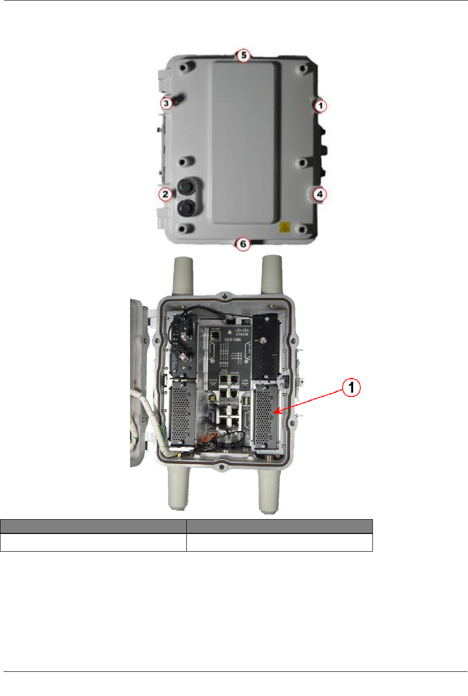
Open CGR Door
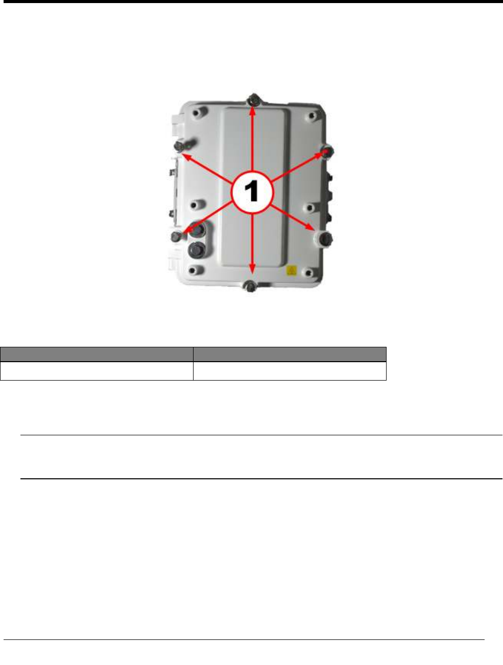
Illustration Callout Number Description
1 CGR door retaining bolts
1. Loosen the six captive bolts that secure the hinged CGR door using the sequence shown below and swing
the door fully open.
Note The CGR door features an environmental seal that protects the unit against environmental elements
when the door is closed. This seal creates pressure, which can cause the door to open suddenly when the
last bolt is loosened.
C
H A P T E R
3
CAM Installation for RF Only Applications
CAM Installation
for RF Only Applications
OpenWay® Riva™ CAM / ACT Coupler Unit 6
Illustration Callout Number Description
1 Slot #5 slot with blank cover
2. Loosen the two captive screws on the blank cover over slot #5 and remove the cover. Use either a #2
Phillips or a 9/32" flat blade screwdriver.

CAM Installation
for RF Only Applications
OpenWay® Riva™ CAM / ACT Coupler Unit 7
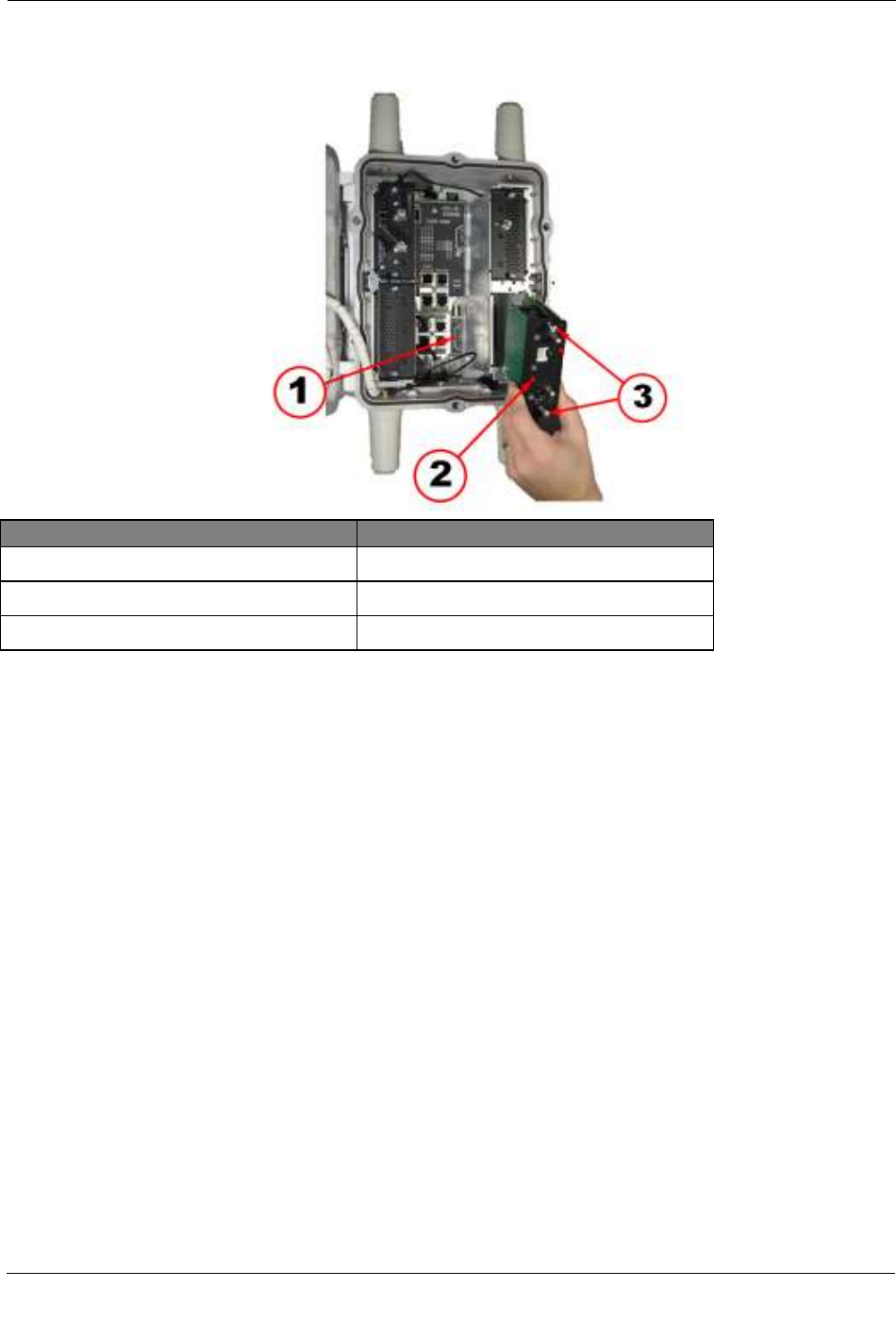
Install CAM for RF Only Applications
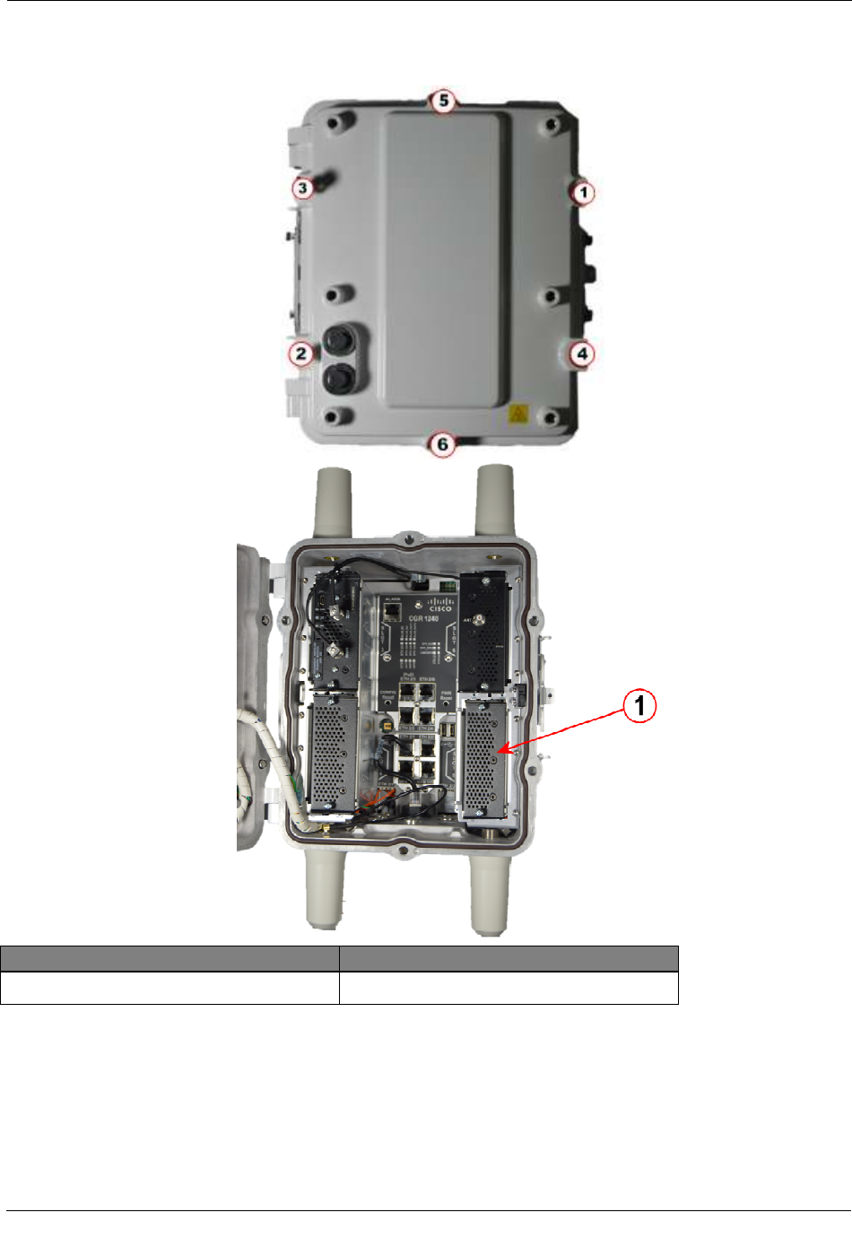
Illustration Callout Number Description
1 Slot #5 identifier label
2 CAM (OW1)
3 CAM retaining screws
1. Locate slot #5 by the slot identifier label inside the CGR.
2. Insert the CAM in slot #5 of the CGR. Ensure the CAM is oriented so that the connectors on the rear of
the CAM are aligned with those in the slot #5. Gently press the CAM until the card-edge connector on the
CAM is firmly seated into the connector in the CGR.
3. Tighten the retaining screws on the front of the CAM securing the module in place. Use either a #2
Phillips or a 9/32" flat blade screwdriver.
CAM Installation
for RF Only Applications
OpenWay® Riva™ CAM / ACT Coupler Unit 8
Illustration Callout Number Description
1 Antenna cable connection
2 WPAN antenna
4. Secure the black antenna wire from the WPAN antenna to the bottom antenna connector on the front of
the CAM.
5. Ensure the antenna cable is routed so that it does not interfere with door closure. Use a single plastic cable
tie to secure the antenna cable to the tie loop on the front of the CAM.
6. Close the door and secure by tightening the six captive bolts using the sequence shown below. Use a
torque of 6-7 foot-pounds when tightening the bolts.
CAM Installation
for RF Only Applications
OpenWay® Riva™ CAM / ACT Coupler Unit 9
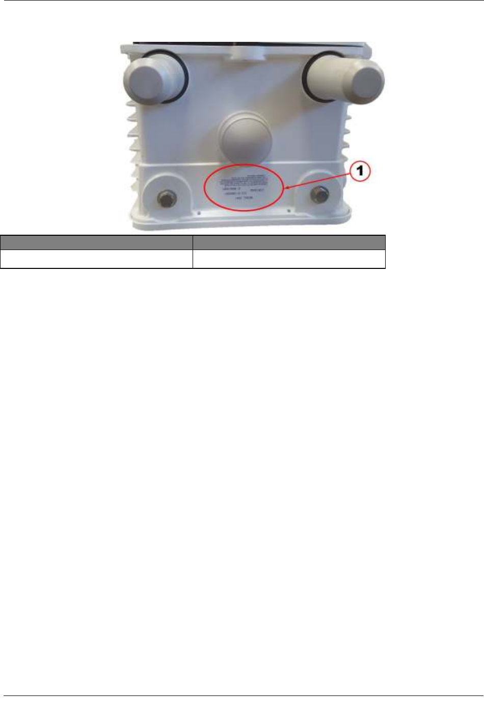
7. Affix the regulatory label (included in the CAM installation kit) to the bottom of the CGR in the label
location provided between the antennas.
Illustration Callout Number Description
1 FCC regulatory label

OpenWay® Riva™ CAM / ACT Coupler Unit 10
The following procedure is for CAM installations that are RF and PLC applications.
Open CGR Door
Illustration Callout Number Description
1 CGR door retaining bolts
1. Loosen the six captive bolts that secure the hinged CGR door using the sequence shown below and swing
the door fully open.
Note The CGR door features an environmental seal that protects the unit against environmental elements
when the door is closed. This seal creates pressure, which can cause the door to open suddenly when the
last bolt is loosened.
C
H A P T E R
4
CAM Installation for RF/PLC Applications
CAM Install
ation for RF/PLC Applications
OpenWay® Riva™ CAM / ACT Coupler Unit 11
Illustration Callout Number Description
1 Slot #5 slot with blank cover
2. Loosen the two captive screws on the blank cover over slot #5 and remove the cover. Use either a #2
phillips or a 9/32" flat blade screwdriver.
CAM Installation for RF/PLC Applications
OpenWay® Riva™ CAM / ACT Coupler Unit 12
Install CAM for RF/PLC Applications
Illustration Callout Number Description
1 Slot #5 identifier label
2 CAM (OW1)
3 CAM retaining screws
1. Locate Slot #5 by the slot identifier label in the CGR.
2. Insert the CAM in slot #5 of the CGR. Ensure the CAM is oriented so that the connectors on the rear of
the CAM are aligned with those in the slot #5. Gently press the CAM until the card-edge connector on the
CAM is firmly seated into the connector in the CGR.
3. Tighten the retaining screws on the front of the CAM securing the module in place. Use either a #2
Phillips or a 9/32" flat blade screwdriver.
CAM Installation for RF/PLC Applications
OpenWay® Riva™ CAM / ACT Coupler Unit 13
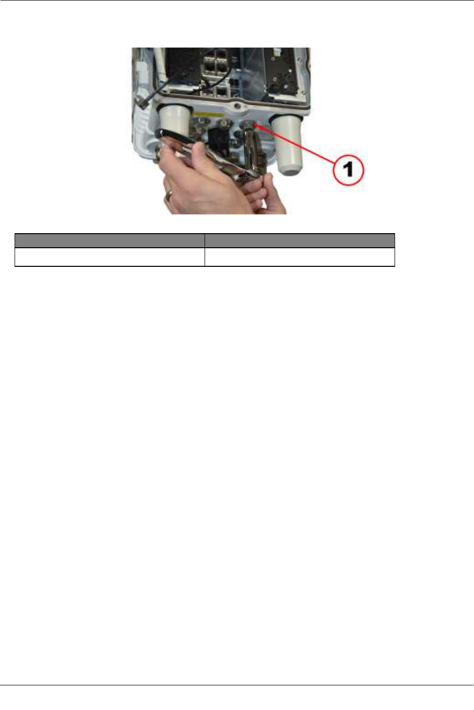
Illustration Callout Number Description
1 PLC signal cable plug
4. Remove the PLC signal cable hole plug using a 13mm socket wrench.
CAM Insta
llation for RF/PLC Applications
OpenWay® Riva™ CAM / ACT Coupler Unit 14
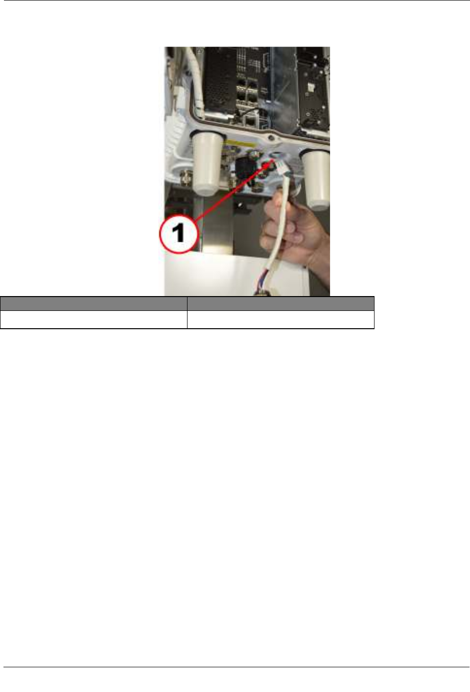
Illustration Callout Number Description
1 PLC signal cable connection routing
5. Insert the PLC signal cable into the CGR.
CAM Installation for RF/PLC Applications
OpenWay® Riva™ CAM / ACT Coupler Unit 15
6. Route the PLC signal cable through access hole and secure the cable gland into the threaded hole. Use a
15/16" combination wrench to secure the gland.
CAM Installation for RF/PLC Applications
OpenWay® Riva™ CAM / ACT Coupler Unit 16
Illustration Callout Number Description
1 PLC signal cable connection
7. Insert the PLC signal cable into the connector on the front of the CAM.
CAM Ins
tallation for RF/PLC Applications
OpenWay® Riva™ CAM / ACT Coupler Unit 17
Illustration Callout Number Description
1 Antenna cable connection
2 WPAN antenna
8. Secure the black antenna wire from the WPAN antenna to the bottom antenna connector on the front of
the CAM.
CAM Installation for RF/PLC Applications
OpenWay® Riva™ CAM / ACT Coupler Unit 18
.
Illustration Callout Number Description
1 PLC cable
2 Antenna cable connection
3 Plastic cable tie
9. Ensure the cables are routed so that they do not interfere with door closure. Use a single plastic cable tie to
secure the PLC cable and the antenna cable to the tie loop on the front of the CAM.
10. Close the door and secure by tightening the six captive bolts using the sequence shown below. Use a
torque of 6-7 foot-pounds when tightening the bolts.

CAM Installation for RF/PLC Applications
OpenWay® Riva™ CAM / ACT Coupler Unit 19
11. Affix the regulatory label, included in the CAM installation kit, to the bottom of the CGR in the label
location provided between the antennas.
Illustration Callout Number Description
1 FCC regulatory label

CAM Installation for RF/PLC Applications
OpenWay® Riva™ CAM / ACT Coupler Unit 20
OpenWay® Riva™ CAM / ACT Coupler Unit 21
This procedure is for installing a Cisco Grid Router (CGR) Adaptive Communications Technology (ACT)
Module (CAM) and the ACT Coupler Unit (ACU) to an existing pole mounted CGR application. To install
the CGR refer to the CGR installation procedure in the Cisco 1240 Connected Grid Router Hardware
Installation Guide.
Disconnect CGR Cables
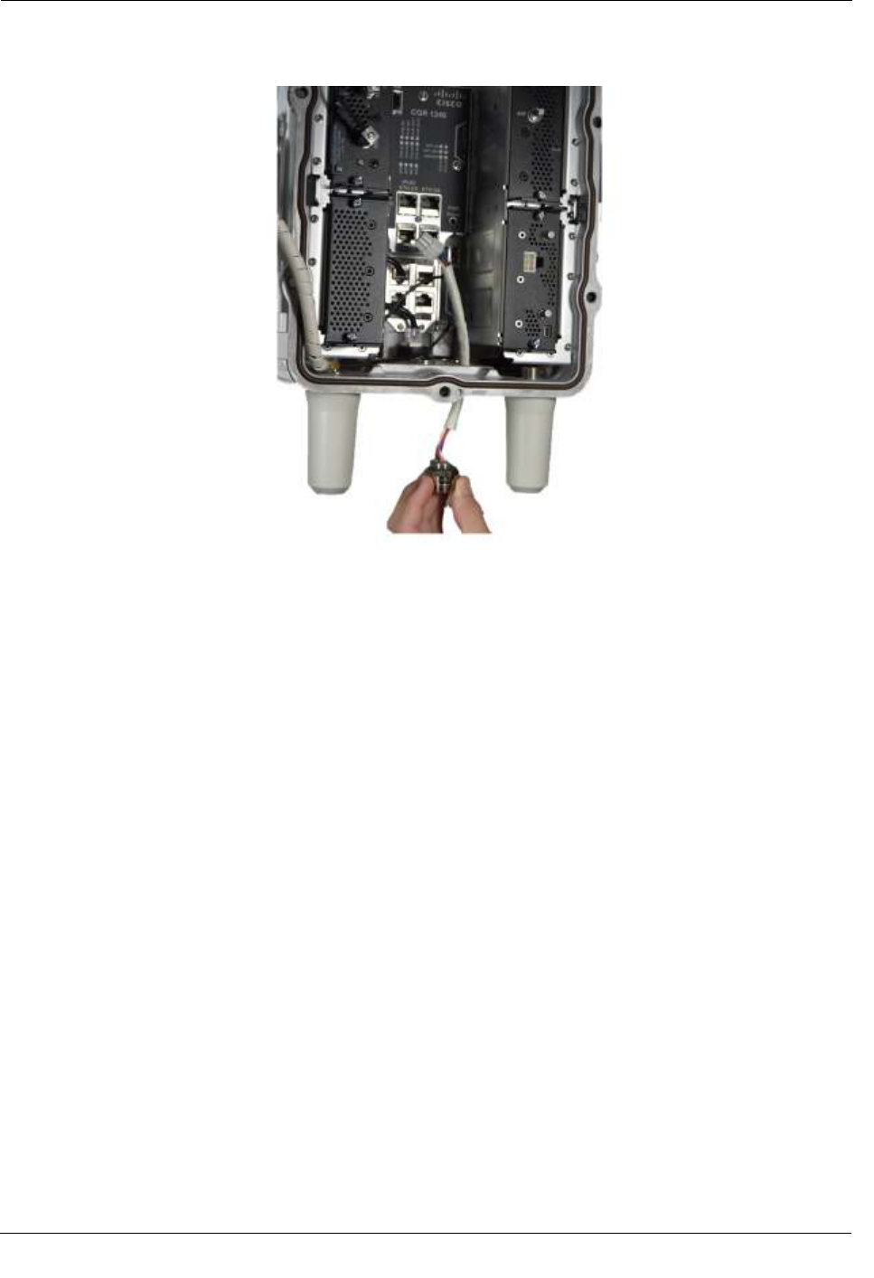
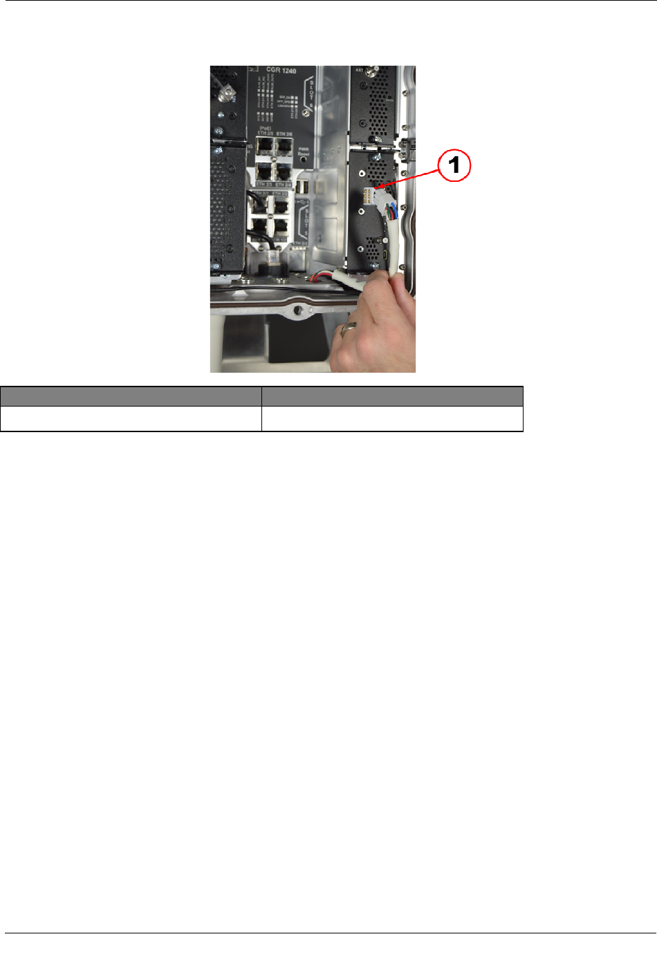
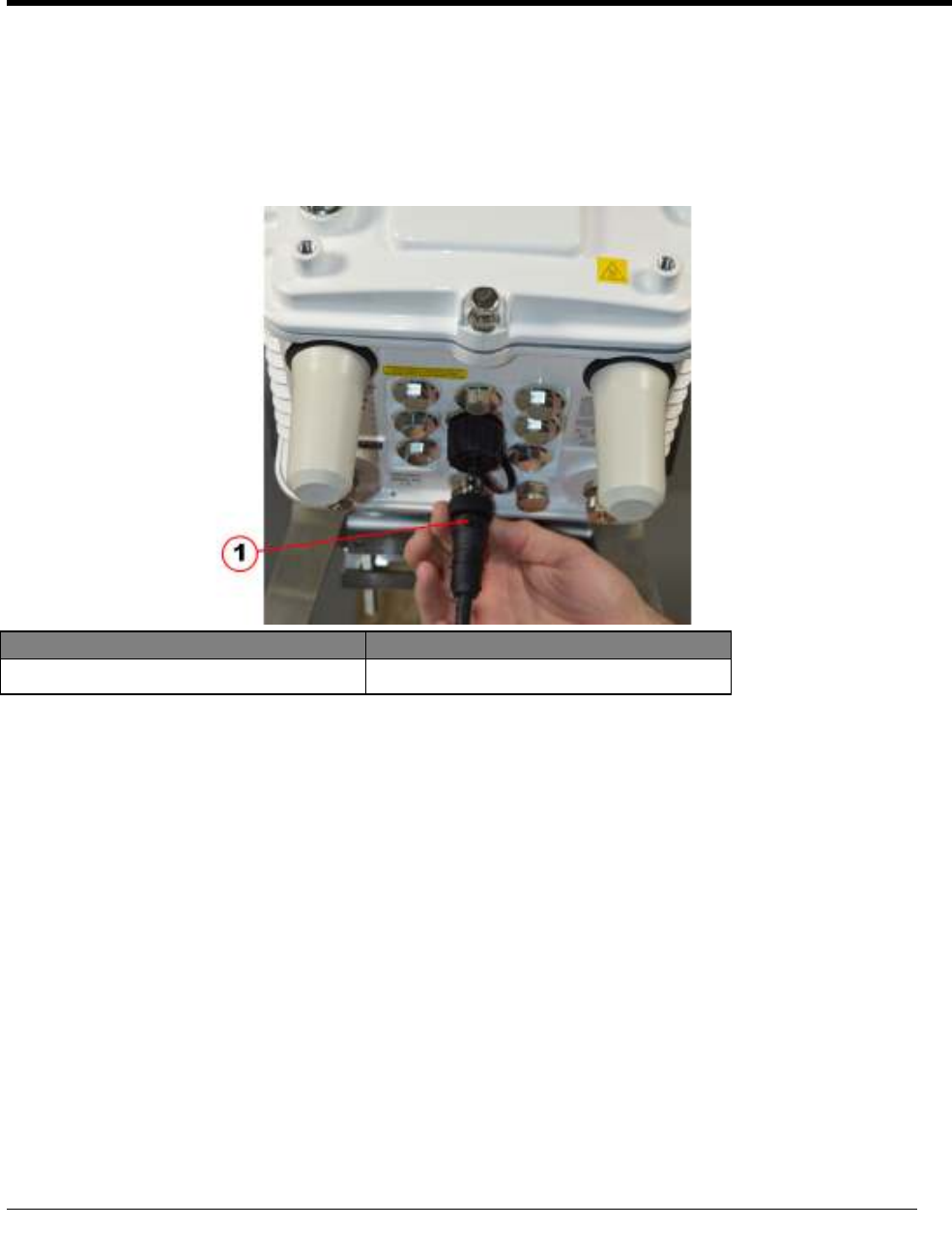
Illustration Callout Number Description
1 CGR power cable
1. Disconnect the power source from the CGR and remove the power cable. This cable will be replaced by
the power cable provided in the coupler unit installation kit.
C
H A P T E R
5
CGR ACT Coupler Unit Installation

CGR ACT Coupler
Unit Installation
OpenWay® Riva™ CAM / ACT Coupler Unit 22
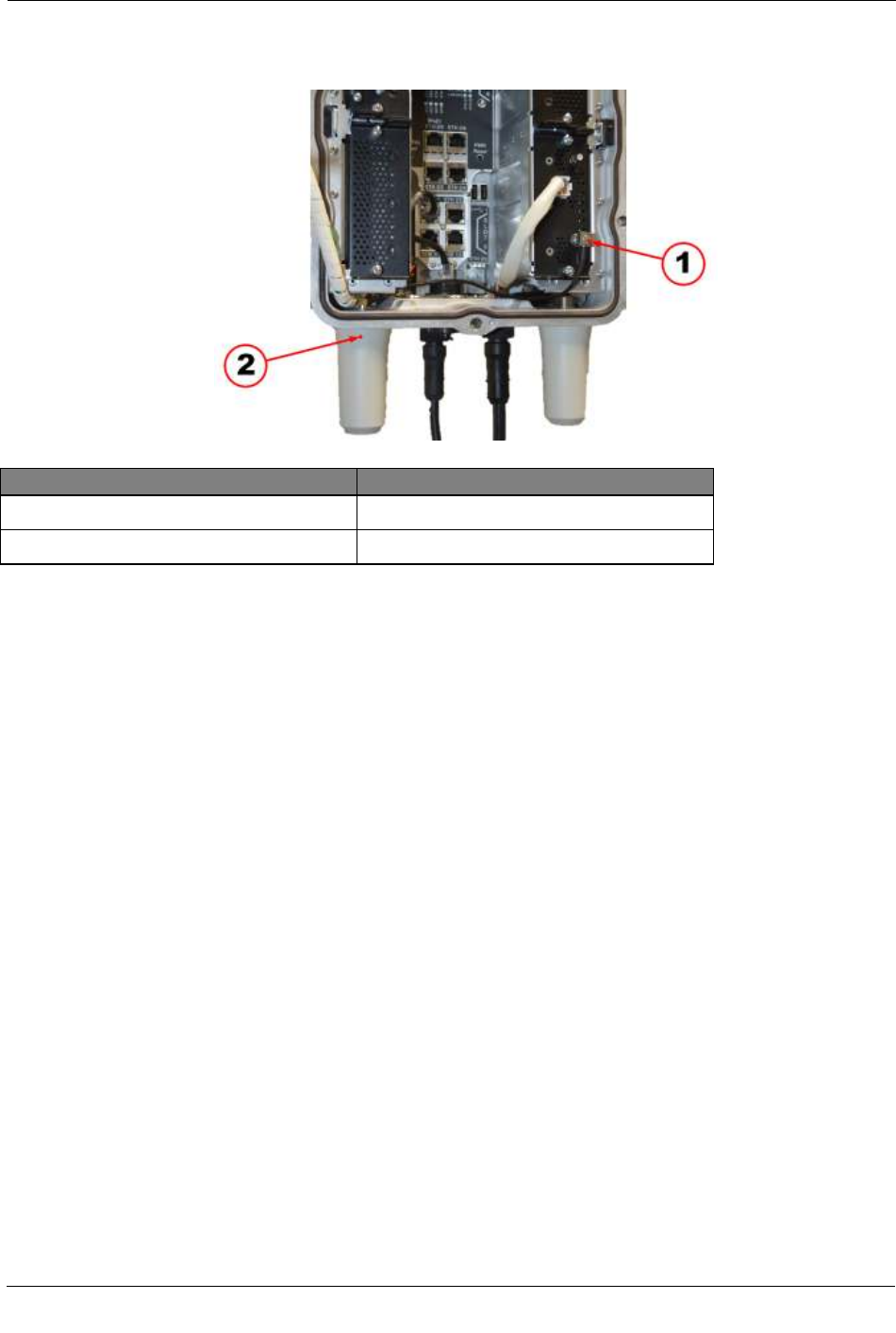
Illustration Callout Number Description
1 Ground Lug
2 CGR 6 AWG ground cable
2. Remove two screws from the ground lug and disconnect the ground cable from the CGR.
CGR ACT Coupler
Unit Installation
OpenWay® Riva™ CAM / ACT Coupler Unit 23
Remove CGR from Mounting
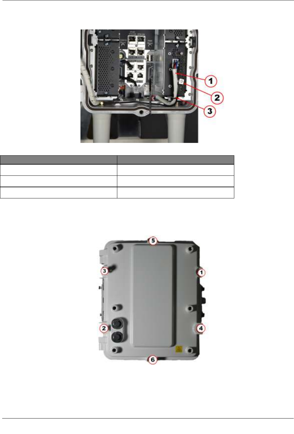
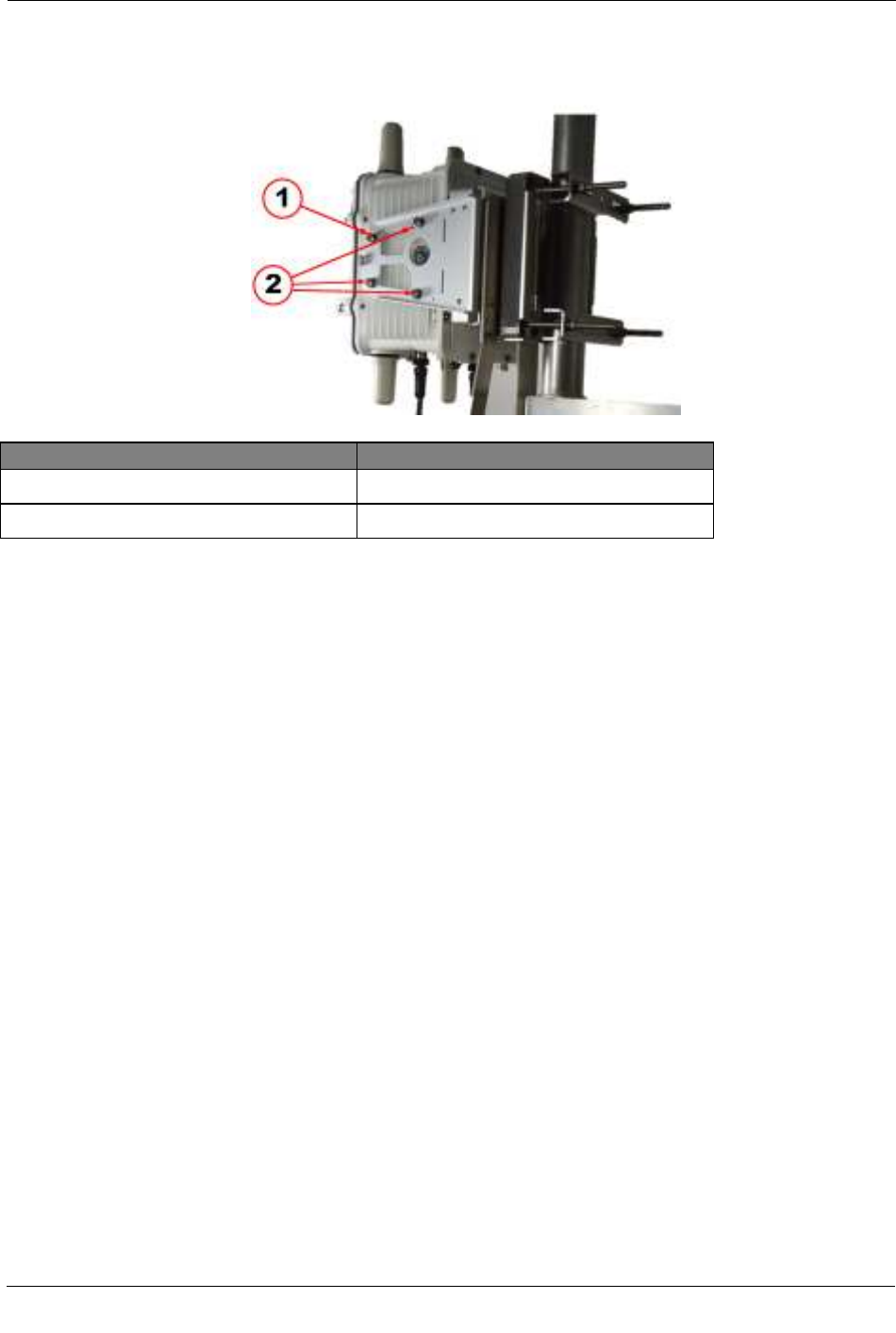
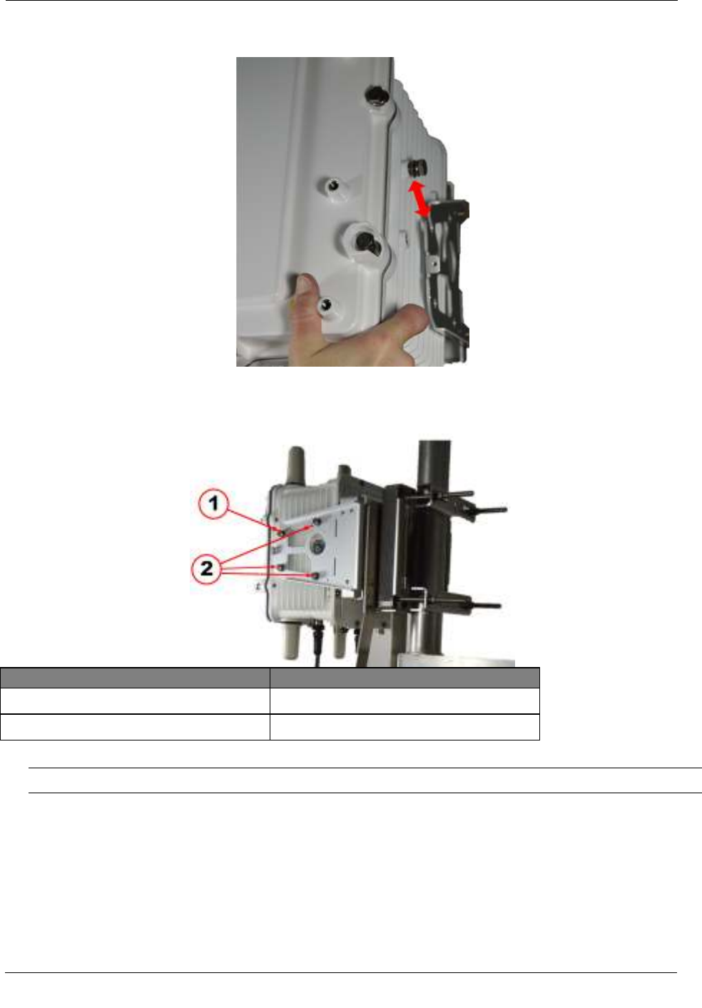
Illustration Callout Number Description
1 Mounting bolt to be loosened
2 Mounting bolts to be completely removed
1. Loosen the top front hex head bolt on each side but do not completely remove.
2. Remove the two rear and lower front hex head bolts on each side of the CGR mounting bracket.
CGR ACT Coupler
Unit Installation
OpenWay® Riva™ CAM / ACT Coupler Unit 24
Remove CGR Mounting Bracket
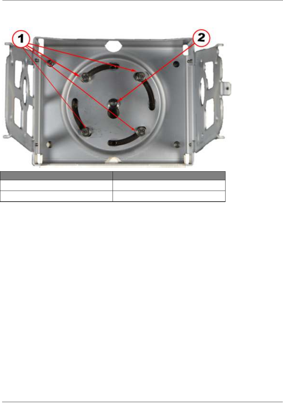
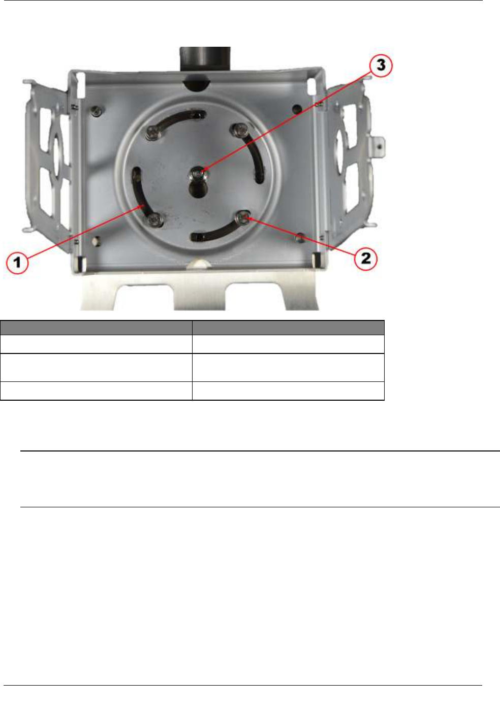
Illustration Callout Number Description
1 Hex head mounting bolts
2 Center stud with self-locking hex nut
1. Remove the four hex head bolts and set aside. Longer bolts are required to accommodate the coupler unit
bracket and are provided in the ACT Coupler unit installation kit.
2. Loosen the center self-locking hex nut to allow the bracket to slide upward and off the center stud.
CGR ACT Coupler
Unit Installation
OpenWay® Riva™ CAM / ACT Coupler Unit 25
Install Coupler Mounting Bracket
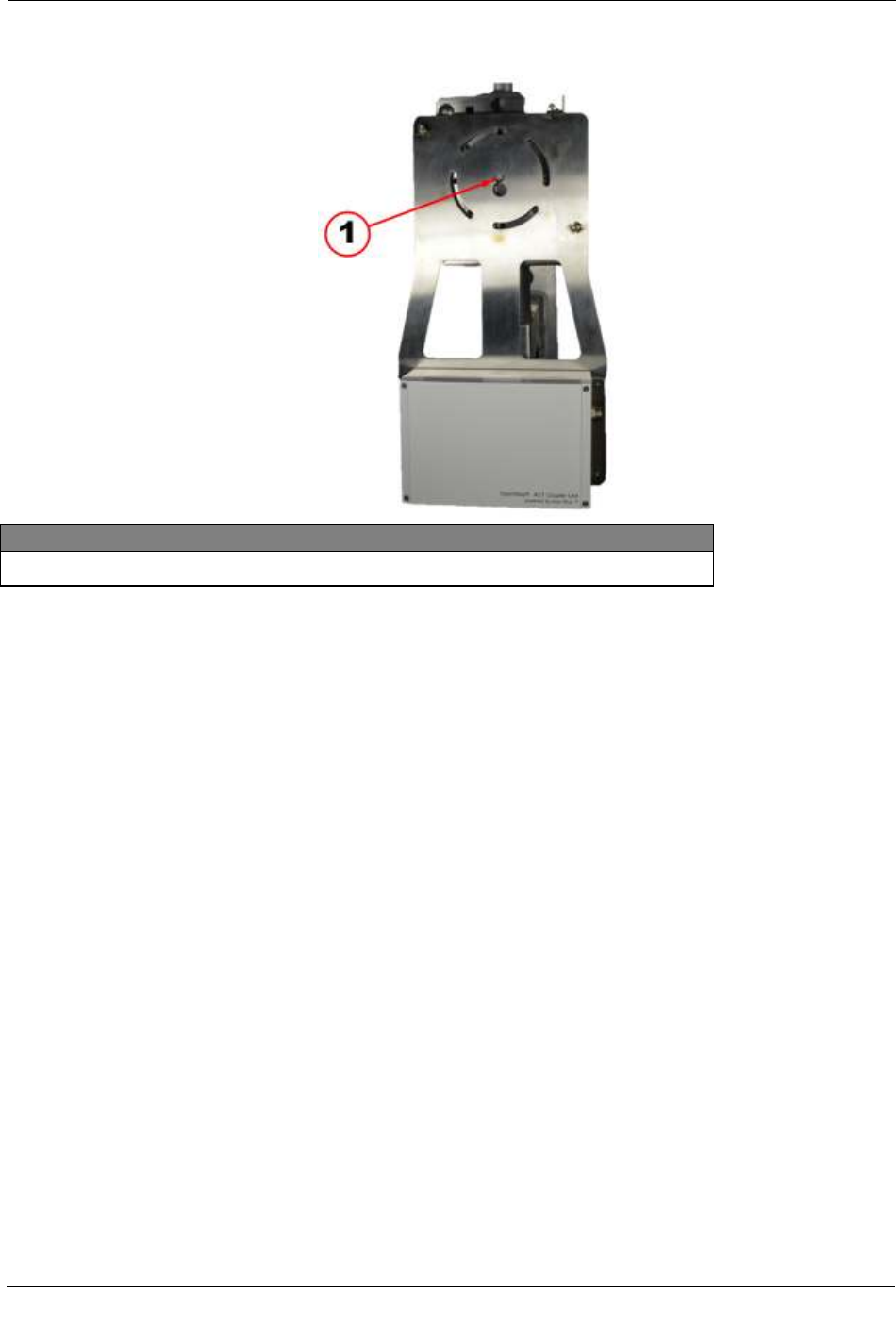
Illustration Callout Number Description
1 Center stud with self-locking hex nut
1. Slide the coupler mounting bracket keyhole slot over the center stud on the pole mount base plate.
CGR ACT Coupler
Unit Installation
OpenWay® Riva™ CAM / ACT Coupler Unit 26
Install CGR Mounting Bracket
Illustration Callout Number Description
1 Alignment slots
2 4 - Hex head mounting bolts (8mm x 25mm)
supplied with the installation kit
3 Center stud with self-locking hex nut
1. Position the CGR mounting bracket over the center stud and slid down behind hex nut.
2. Insert the four 8mm x 25mm mounting screws supplied with the installation kit into the threaded holes in
the base mounting plate. Do not tighten bolts until all are started.
Note The four alignment slots in the mounting brackets allow the CGR and the coupler unit to be rotated
either clockwise or counter clockwise for alignment purposes. Inserting the mounting bolts as shown
allow the unit to rotate counter clockwise. Inserting all four bolts in the holes at the other end of the slot
allows the unit to be rotated clockwise.
3. Adjust the alignment of the CGR and coupler to the desired orientation and tighten the four mounting
bolts and the hex nut on the center stud. Use a torque of 6-7 foot-pounds when tightening the bolts and
nut.
CGR ACT Coupler
Unit Installation
OpenWay® Riva™ CAM / ACT Coupler Unit 27
Install the CGR
1. Mount the CGR to the mounting bracket by sliding the mounting bolt in the top front position on each side
of the CGR into the corresponding slot on the mounting bracket.
Illustration Callout Number Description
1 Mounting bolt not completely removed
2 Mounting bolts to be completely removed
2. Insert the remaining three bolts on each side of the CGR into their respective places.
Note Insert all mounting bolts on each side before securing tightly.
3. Tighten all mounting bolts. Use a torque of 6-7 foot-pounds when tightening the bolts.
CGR ACT Coupler
Unit Installation
OpenWay® Riva™ CAM / ACT Coupler Unit 28
Connect CGR Cables
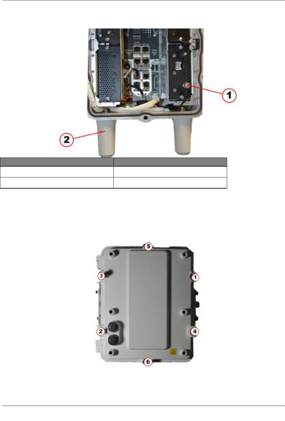
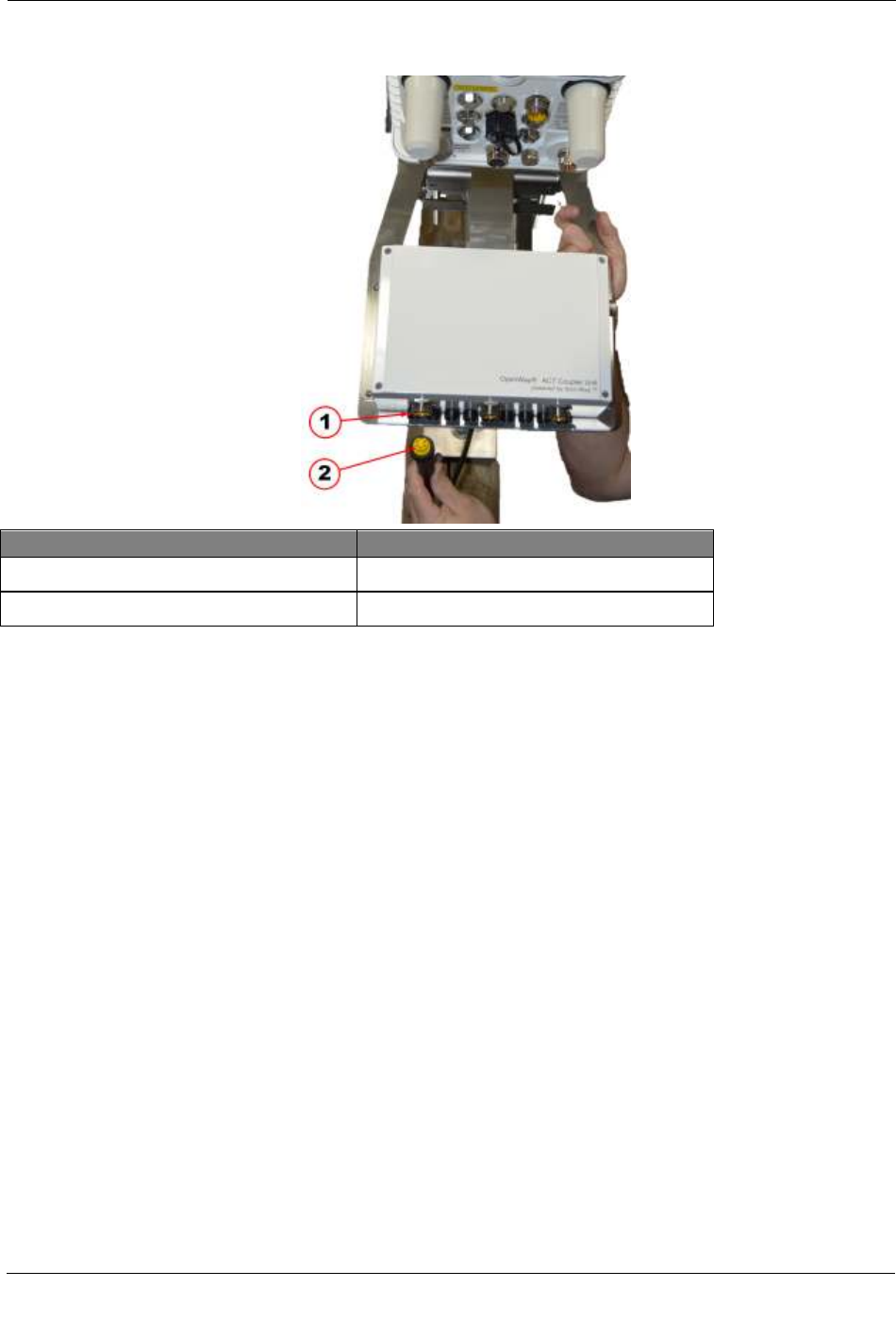
Illustration Callout Number Description
1 Coupler unit power input bulkhead connector
2 Coupler unit power cable
1. Connect the 5-pin external power supply cable to the left most connector on the bottom of the coupler
unit.
CGR ACT Coupler
Unit Installation
OpenWay® Riva™ CAM / ACT Coupler Unit 29
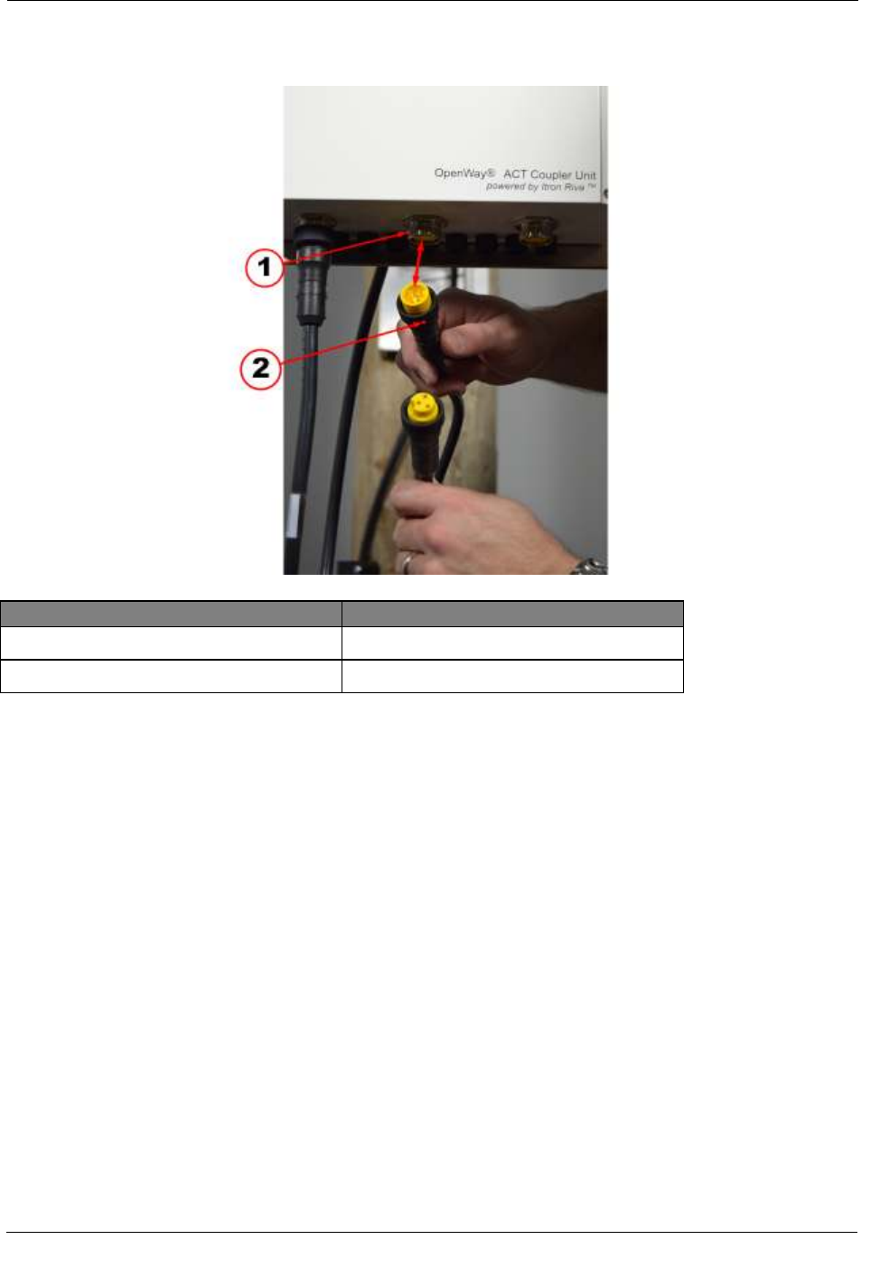
Illustration Callout Number Description
1 Coupler unit power bulkhead connector
2 Coupler unit to CGR power cable
2. Connect the 5-pin male end connector of the coupler unit to CGR power to the power output (center)
bulkhead connector on the bottom of the coupler unit.
CGR ACT Coupler
Unit Installation
OpenWay® Riva™ CAM / ACT Coupler Unit 30
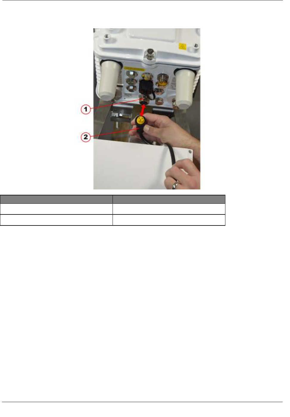
Illustration Callout Number Description
1 CGR power bulkhead connector
2 Coupler unit to CGR power cable
3. Connect the 3-pin female end of the coupler unit to CGR power cable to the power input bulkhead
connector on the bottom of the CGR.

CGR ACT Coupler
Unit Installation
OpenWay® Riva™ CAM / ACT Coupler Unit 31
Illustration Callout Number Description
1 PLC signal bulkhead connector
2 PLC signal cable
4. Connect the 6-pin male end of PLC signal cable to the PLC bulkhead connector on the ACT coupler unit.

CGR ACT Coupler
Unit Installation
OpenWay® Riva™ CAM / ACT Coupler Unit 32
5. Connect the 6-pin female end of the PLC signal cable to the male PLC signal bulkhead connector on the
CGR.
CGR ACT Coupler
Unit Installation
OpenWay® Riva™ CAM / ACT Coupler Unit 33
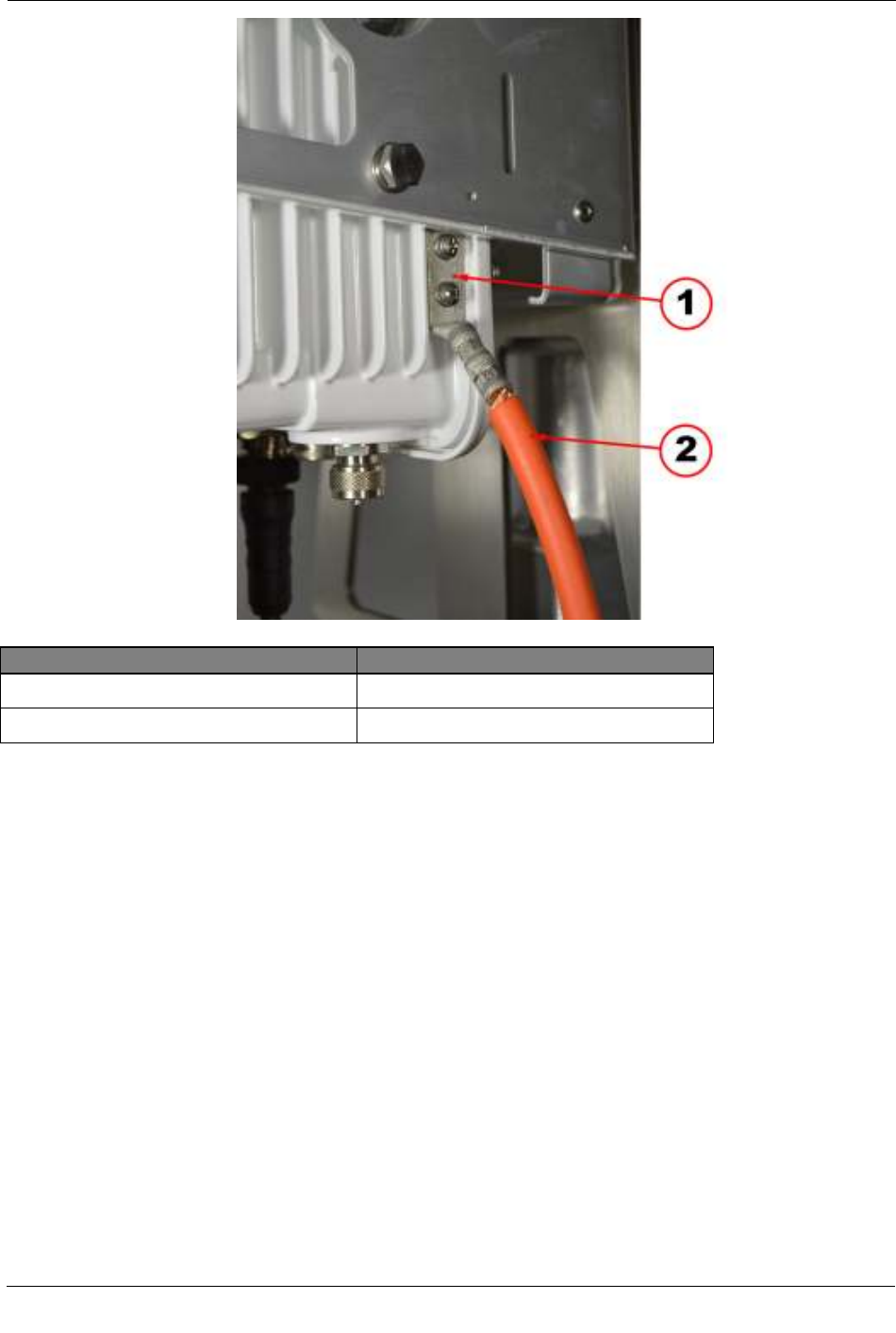
Illustration Callout Number Description
1 Ground Lug
2 CGR 6 AWG ground cable
6. Insert the two screws for the ground lug to connect the ground cable to the CGR. Use a torque of 10-12
foot-pounds when tightening the grounding screws.