Itron RIVAWA AMR transceiver device for utility meters User Manual Installation Guide
Itron Inc AMR transceiver device for utility meters Installation Guide
Itron >
Contents
- 1. Users Manual 1
- 2. Users Manual 2
- 3. Users Manual
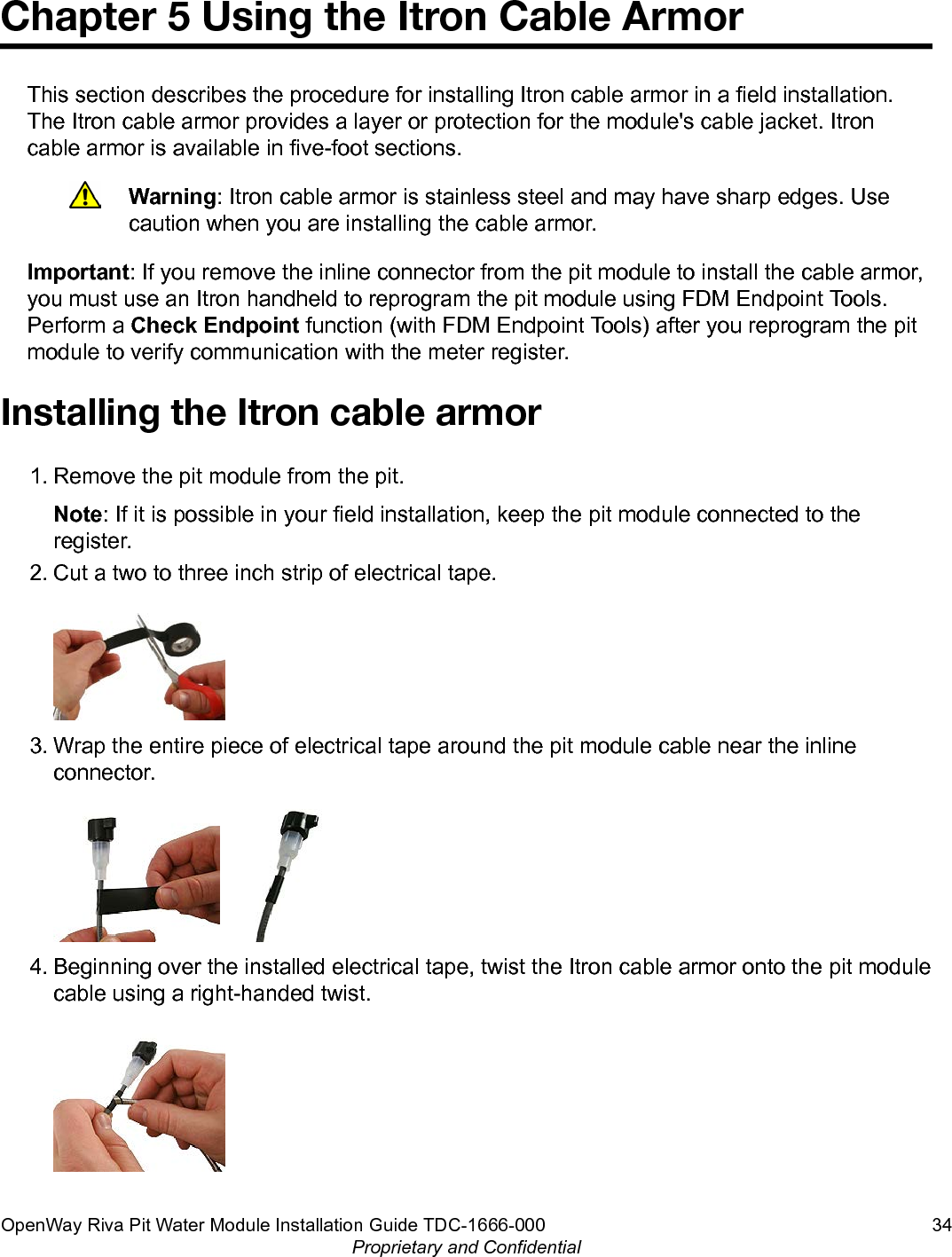
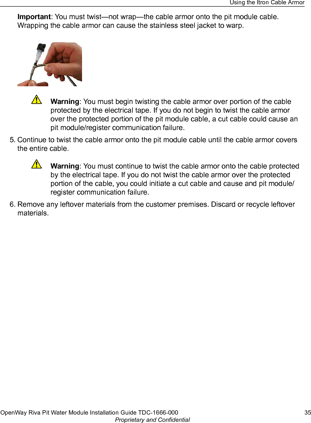
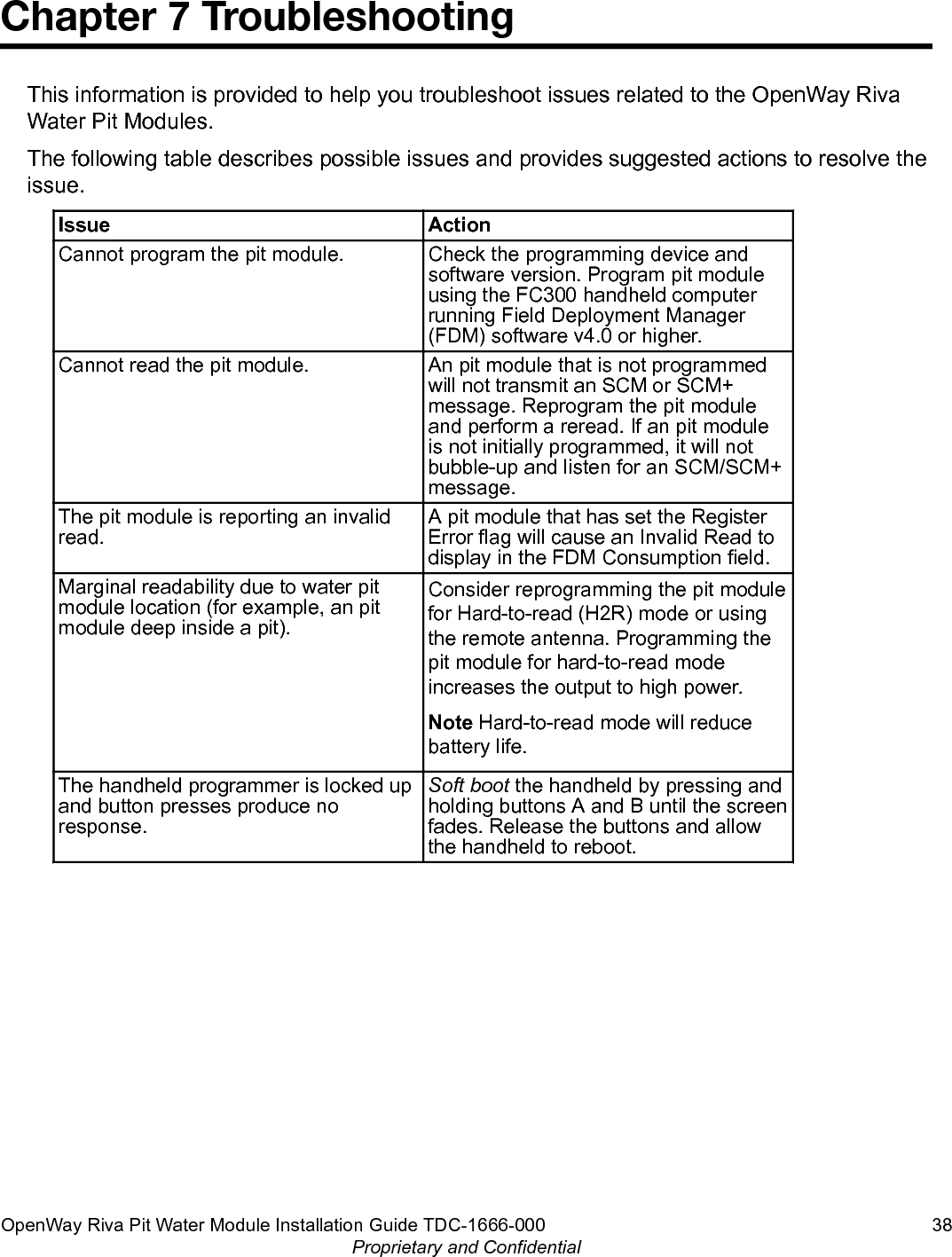
Users Manual 2