Itron SGRCWZ Cellular/ PCS GSM/ EDGE/ WCDMA Hub with WLAN and Zigbee User Manual
Itron Cellular/ PCS GSM/ EDGE/ WCDMA Hub with WLAN and Zigbee Users Manual
UserManual.wiki
>
Itron
>
SGRCWZ User Manual
Users Manual
Navigation menu
Upload a User Manual
Namespaces
Wiki Guide
HTML
PDF
Info
Views
User Manual
Discussion / Help
Navigation
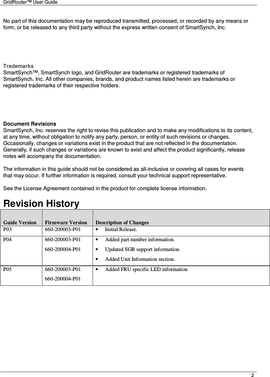
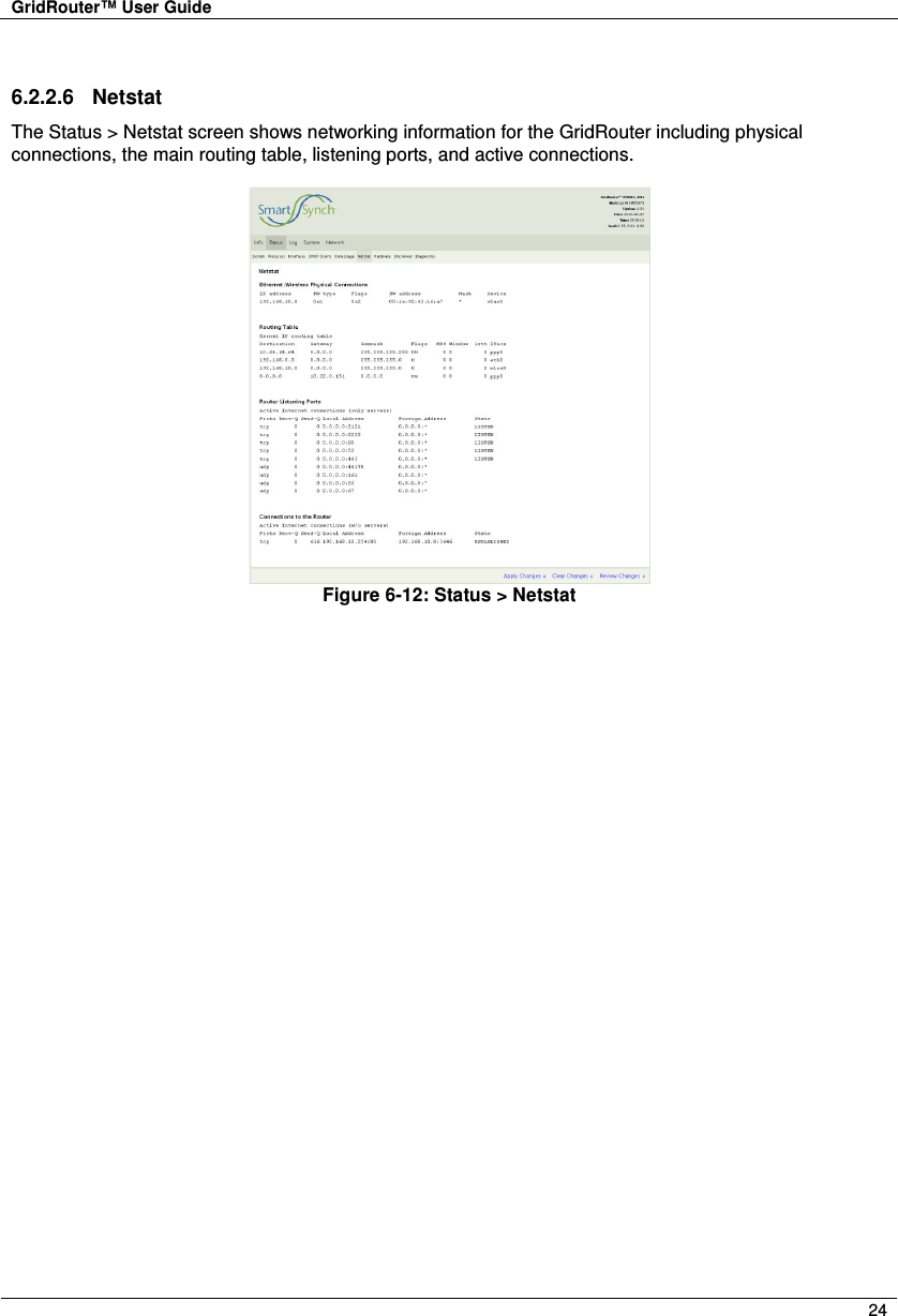
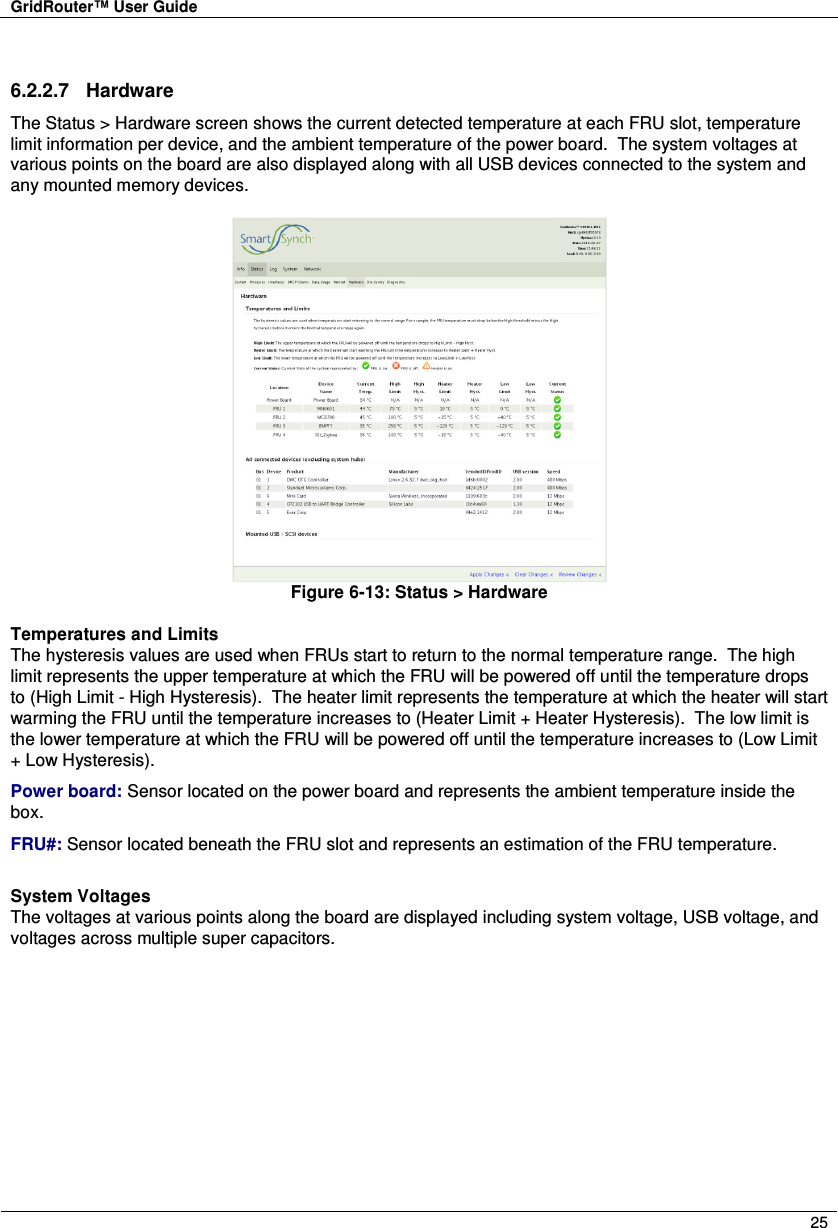
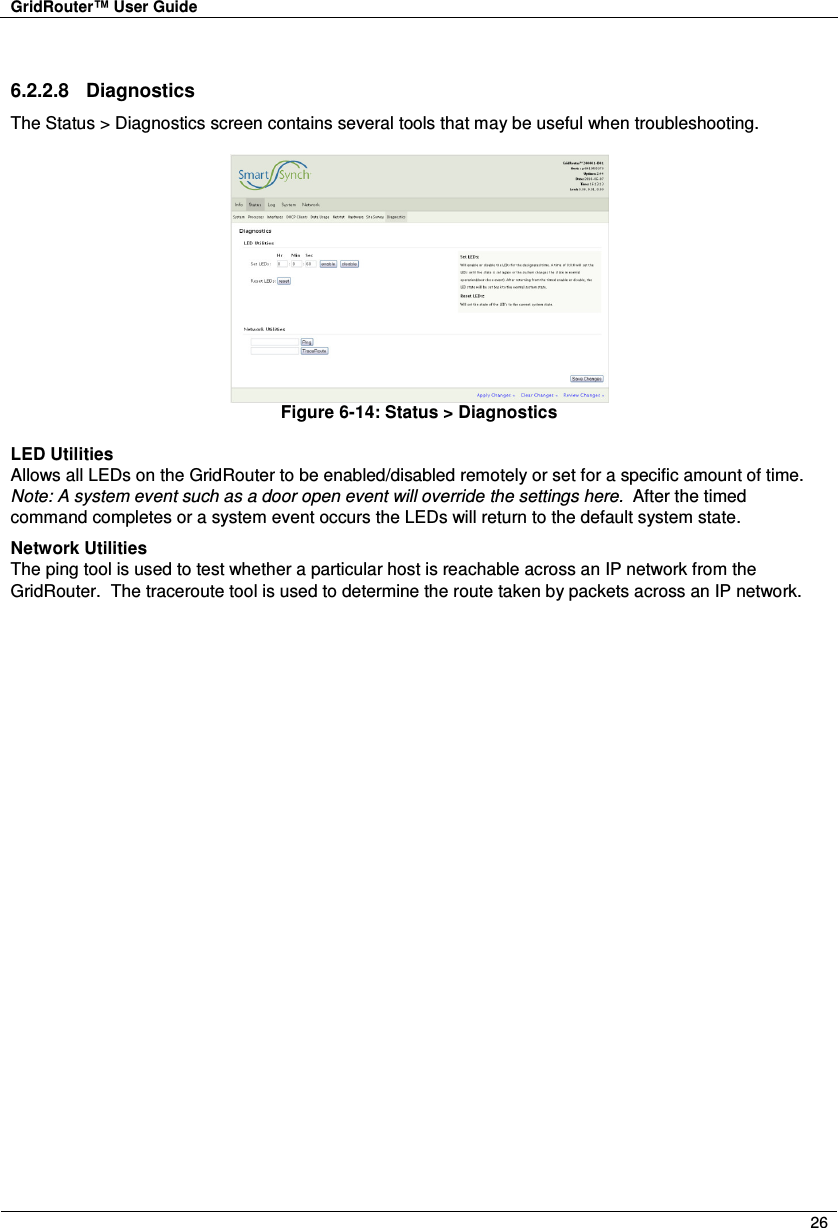
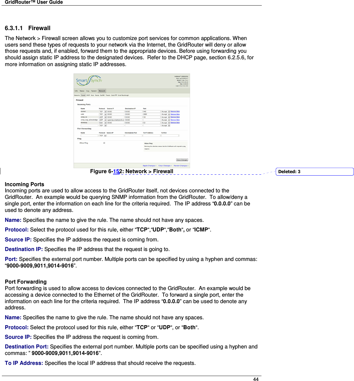
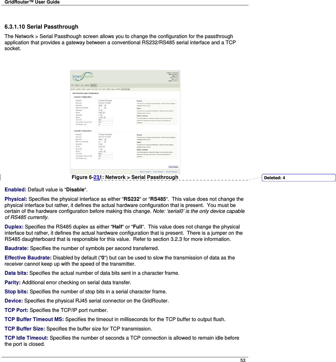
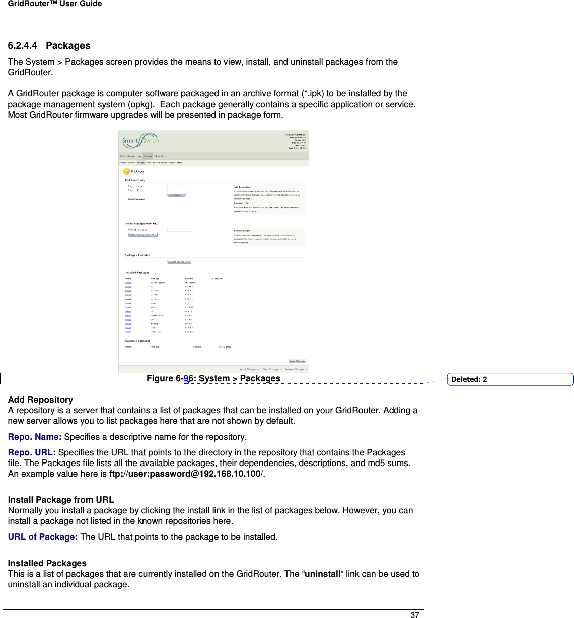
![GridRouter™ User Guide 34 6.2.4 System 6.2.4.1 Settings The System > Settings screen allows for configuration of GridRouter’s time zone and NTP servers. Figure 6-23: System > Settings Time Settings Timezone: Specifies the time zone for the GridRouter which is mainly used for accurate time stamps in the log files. The drop down box includes all time zones. POSIX TZ String: [Read-only] Specifies the POSIX TZ string for reference. Primary NTP Server: Specifies the URL to the primary NTP server. Secondary NTP Server: Specifies the URL to the secondary NTP server.](https://usermanual.wiki/Itron/SGRCWZ/User-Guide-1654923-Page-34.png)
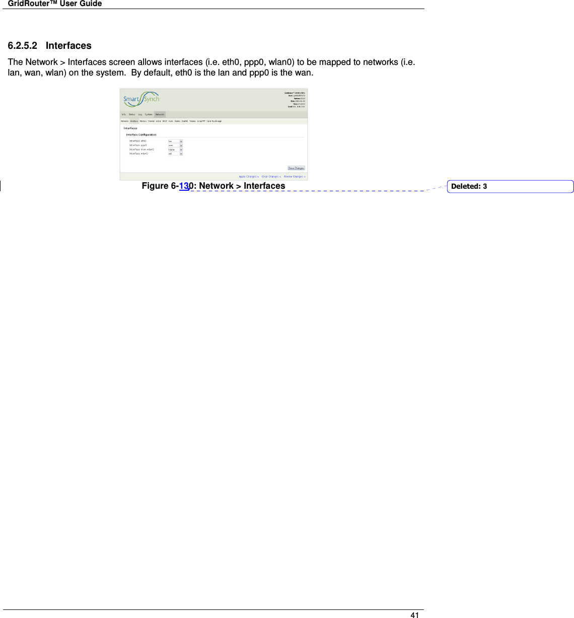
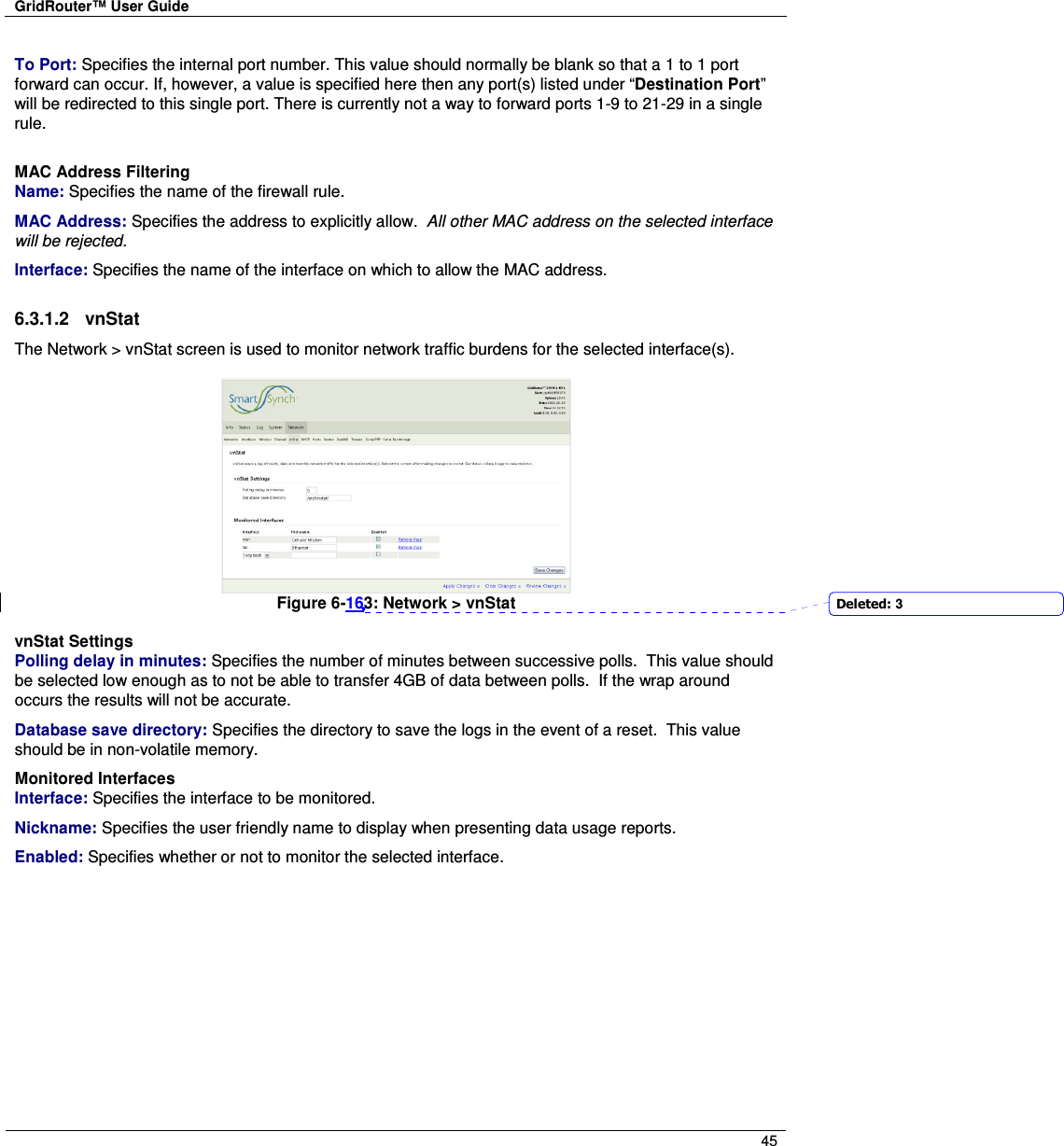
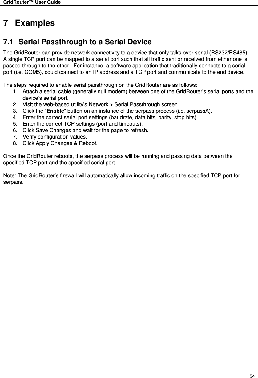
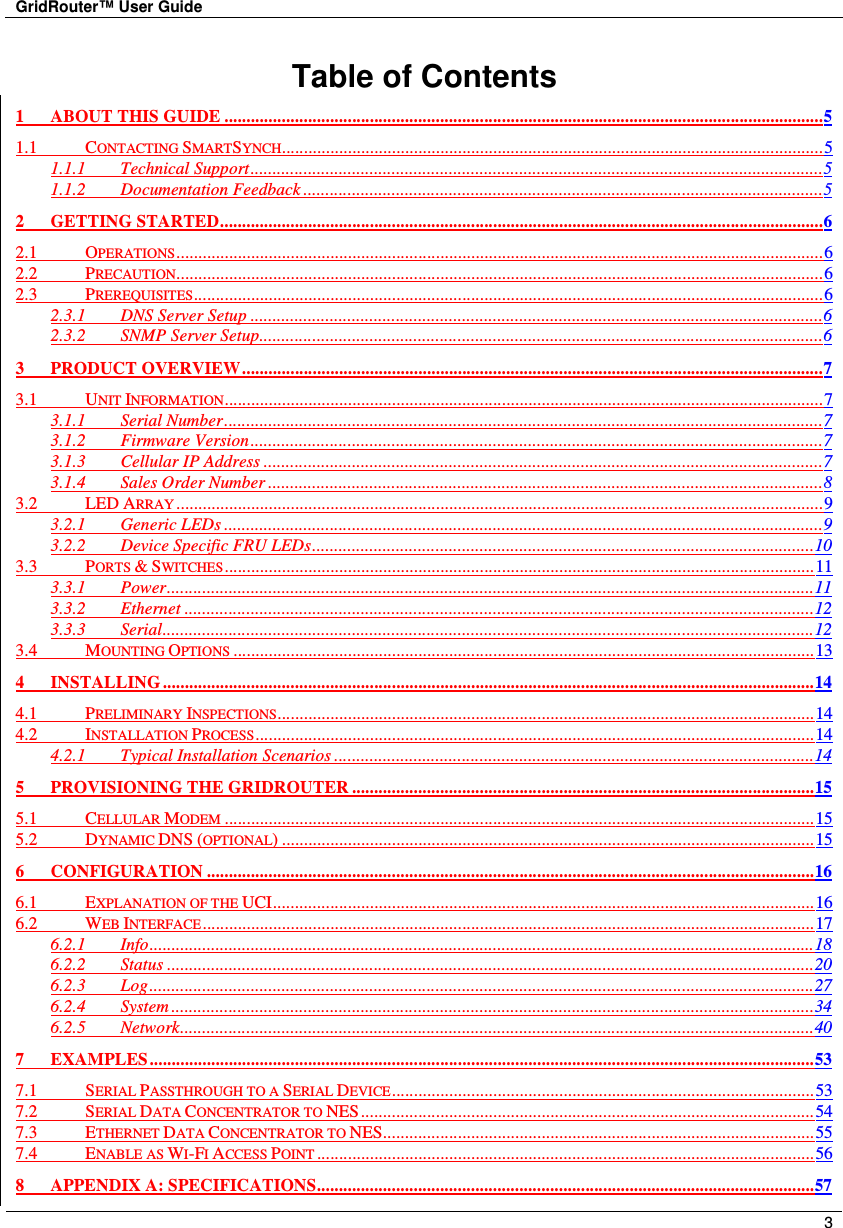
![GridRouter™ User Guide 43 Enable as Wi-Fi Access Point”. Figure 6-141: Network > Interfaces Wireless Adapter radio Configuration To change the physical aspects of the wireless card, edit these options. Radio: Turns broadcasting on or off for the device. Channel: Specifies the physical channel the radio is broadcasting on. Wireless Distance: Used to set the transmit power of the device. [Unused] Wireless Virtual Adaptor Configuration To change the software settings for the wireless card, edit these options. Network: Affiliates a wireless card with a network on the system. This value will often be set to “wlan” or “wifi” depending on the name of the interface that was added. Mode: Sets the wireless card to be an “Access Point”, “Client”, or “Ad Hoc”. Currently only “Access Point” is supported. AP Isolation: This isolates all wireless devices on the GridRouter network from each other. [Unused]. RTS: Request to send threshold. Fragmentation: Fragmentation threshold. ESSID: Specifies the broadcasted name of the Access Point. Encryption Type: Encryption type used. Deleted: Enable as Wi-Fi Access PointDeleted: 3](https://usermanual.wiki/Itron/SGRCWZ/User-Guide-1654923-Page-43.png)